WO2014087474A1 - 車両の制御システム - Google Patents
車両の制御システム Download PDFInfo
- Publication number
- WO2014087474A1 WO2014087474A1 PCT/JP2012/081312 JP2012081312W WO2014087474A1 WO 2014087474 A1 WO2014087474 A1 WO 2014087474A1 JP 2012081312 W JP2012081312 W JP 2012081312W WO 2014087474 A1 WO2014087474 A1 WO 2014087474A1
- Authority
- WO
- WIPO (PCT)
- Prior art keywords
- vehicle
- ecu
- control device
- predetermined value
- driving torque
- Prior art date
- Legal status (The legal status is an assumption and is not a legal conclusion. Google has not performed a legal analysis and makes no representation as to the accuracy of the status listed.)
- Ceased
Links
Images



Classifications
-
- F—MECHANICAL ENGINEERING; LIGHTING; HEATING; WEAPONS; BLASTING
- F02—COMBUSTION ENGINES; HOT-GAS OR COMBUSTION-PRODUCT ENGINE PLANTS
- F02D—CONTROLLING COMBUSTION ENGINES
- F02D41/00—Electrical control of supply of combustible mixture or its constituents
- F02D41/02—Circuit arrangements for generating control signals
- F02D41/04—Introducing corrections for particular operating conditions
- F02D41/06—Introducing corrections for particular operating conditions for engine starting or warming up
- F02D41/062—Introducing corrections for particular operating conditions for engine starting or warming up for starting
-
- B—PERFORMING OPERATIONS; TRANSPORTING
- B60—VEHICLES IN GENERAL
- B60K—ARRANGEMENT OR MOUNTING OF PROPULSION UNITS OR OF TRANSMISSIONS IN VEHICLES; ARRANGEMENT OR MOUNTING OF PLURAL DIVERSE PRIME-MOVERS IN VEHICLES; AUXILIARY DRIVES FOR VEHICLES; INSTRUMENTATION OR DASHBOARDS FOR VEHICLES; ARRANGEMENTS IN CONNECTION WITH COOLING, AIR INTAKE, GAS EXHAUST OR FUEL SUPPLY OF PROPULSION UNITS IN VEHICLES
- B60K6/00—Arrangement or mounting of plural diverse prime-movers for mutual or common propulsion, e.g. hybrid propulsion systems comprising electric motors and internal combustion engines
- B60K6/20—Arrangement or mounting of plural diverse prime-movers for mutual or common propulsion, e.g. hybrid propulsion systems comprising electric motors and internal combustion engines the prime-movers consisting of electric motors and internal combustion engines, e.g. HEVs
- B60K6/42—Arrangement or mounting of plural diverse prime-movers for mutual or common propulsion, e.g. hybrid propulsion systems comprising electric motors and internal combustion engines the prime-movers consisting of electric motors and internal combustion engines, e.g. HEVs characterised by the architecture of the hybrid electric vehicle
- B60K6/44—Series-parallel type
- B60K6/445—Differential gearing distribution type
-
- B—PERFORMING OPERATIONS; TRANSPORTING
- B60—VEHICLES IN GENERAL
- B60K—ARRANGEMENT OR MOUNTING OF PROPULSION UNITS OR OF TRANSMISSIONS IN VEHICLES; ARRANGEMENT OR MOUNTING OF PLURAL DIVERSE PRIME-MOVERS IN VEHICLES; AUXILIARY DRIVES FOR VEHICLES; INSTRUMENTATION OR DASHBOARDS FOR VEHICLES; ARRANGEMENTS IN CONNECTION WITH COOLING, AIR INTAKE, GAS EXHAUST OR FUEL SUPPLY OF PROPULSION UNITS IN VEHICLES
- B60K6/00—Arrangement or mounting of plural diverse prime-movers for mutual or common propulsion, e.g. hybrid propulsion systems comprising electric motors and internal combustion engines
- B60K6/20—Arrangement or mounting of plural diverse prime-movers for mutual or common propulsion, e.g. hybrid propulsion systems comprising electric motors and internal combustion engines the prime-movers consisting of electric motors and internal combustion engines, e.g. HEVs
- B60K6/42—Arrangement or mounting of plural diverse prime-movers for mutual or common propulsion, e.g. hybrid propulsion systems comprising electric motors and internal combustion engines the prime-movers consisting of electric motors and internal combustion engines, e.g. HEVs characterised by the architecture of the hybrid electric vehicle
- B60K6/48—Parallel type
-
- B—PERFORMING OPERATIONS; TRANSPORTING
- B60—VEHICLES IN GENERAL
- B60W—CONJOINT CONTROL OF VEHICLE SUB-UNITS OF DIFFERENT TYPE OR DIFFERENT FUNCTION; CONTROL SYSTEMS SPECIALLY ADAPTED FOR HYBRID VEHICLES; ROAD VEHICLE DRIVE CONTROL SYSTEMS FOR PURPOSES NOT RELATED TO THE CONTROL OF A PARTICULAR SUB-UNIT
- B60W10/00—Conjoint control of vehicle sub-units of different type or different function
- B60W10/04—Conjoint control of vehicle sub-units of different type or different function including control of propulsion units
- B60W10/06—Conjoint control of vehicle sub-units of different type or different function including control of propulsion units including control of combustion engines
-
- B—PERFORMING OPERATIONS; TRANSPORTING
- B60—VEHICLES IN GENERAL
- B60W—CONJOINT CONTROL OF VEHICLE SUB-UNITS OF DIFFERENT TYPE OR DIFFERENT FUNCTION; CONTROL SYSTEMS SPECIALLY ADAPTED FOR HYBRID VEHICLES; ROAD VEHICLE DRIVE CONTROL SYSTEMS FOR PURPOSES NOT RELATED TO THE CONTROL OF A PARTICULAR SUB-UNIT
- B60W10/00—Conjoint control of vehicle sub-units of different type or different function
- B60W10/04—Conjoint control of vehicle sub-units of different type or different function including control of propulsion units
- B60W10/08—Conjoint control of vehicle sub-units of different type or different function including control of propulsion units including control of electric propulsion units, e.g. motors or generators
-
- B—PERFORMING OPERATIONS; TRANSPORTING
- B60—VEHICLES IN GENERAL
- B60W—CONJOINT CONTROL OF VEHICLE SUB-UNITS OF DIFFERENT TYPE OR DIFFERENT FUNCTION; CONTROL SYSTEMS SPECIALLY ADAPTED FOR HYBRID VEHICLES; ROAD VEHICLE DRIVE CONTROL SYSTEMS FOR PURPOSES NOT RELATED TO THE CONTROL OF A PARTICULAR SUB-UNIT
- B60W20/00—Control systems specially adapted for hybrid vehicles
-
- B—PERFORMING OPERATIONS; TRANSPORTING
- B60—VEHICLES IN GENERAL
- B60W—CONJOINT CONTROL OF VEHICLE SUB-UNITS OF DIFFERENT TYPE OR DIFFERENT FUNCTION; CONTROL SYSTEMS SPECIALLY ADAPTED FOR HYBRID VEHICLES; ROAD VEHICLE DRIVE CONTROL SYSTEMS FOR PURPOSES NOT RELATED TO THE CONTROL OF A PARTICULAR SUB-UNIT
- B60W20/00—Control systems specially adapted for hybrid vehicles
- B60W20/10—Controlling the power contribution of each of the prime movers to meet required power demand
-
- B—PERFORMING OPERATIONS; TRANSPORTING
- B60—VEHICLES IN GENERAL
- B60W—CONJOINT CONTROL OF VEHICLE SUB-UNITS OF DIFFERENT TYPE OR DIFFERENT FUNCTION; CONTROL SYSTEMS SPECIALLY ADAPTED FOR HYBRID VEHICLES; ROAD VEHICLE DRIVE CONTROL SYSTEMS FOR PURPOSES NOT RELATED TO THE CONTROL OF A PARTICULAR SUB-UNIT
- B60W20/00—Control systems specially adapted for hybrid vehicles
- B60W20/50—Control strategies for responding to system failures, e.g. for fault diagnosis, failsafe operation or limp mode
-
- B—PERFORMING OPERATIONS; TRANSPORTING
- B60—VEHICLES IN GENERAL
- B60W—CONJOINT CONTROL OF VEHICLE SUB-UNITS OF DIFFERENT TYPE OR DIFFERENT FUNCTION; CONTROL SYSTEMS SPECIALLY ADAPTED FOR HYBRID VEHICLES; ROAD VEHICLE DRIVE CONTROL SYSTEMS FOR PURPOSES NOT RELATED TO THE CONTROL OF A PARTICULAR SUB-UNIT
- B60W30/00—Purposes of road vehicle drive control systems not related to the control of a particular sub-unit, e.g. of systems using conjoint control of vehicle sub-units
- B60W30/18—Propelling the vehicle
- B60W30/192—Mitigating problems related to power-up or power-down of the driveline, e.g. start-up of a cold engine
-
- F—MECHANICAL ENGINEERING; LIGHTING; HEATING; WEAPONS; BLASTING
- F02—COMBUSTION ENGINES; HOT-GAS OR COMBUSTION-PRODUCT ENGINE PLANTS
- F02D—CONTROLLING COMBUSTION ENGINES
- F02D11/00—Arrangements for, or adaptations to, non-automatic engine control initiation means, e.g. operator initiated
- F02D11/06—Arrangements for, or adaptations to, non-automatic engine control initiation means, e.g. operator initiated characterised by non-mechanical control linkages, e.g. fluid control linkages or by control linkages with power drive or assistance
- F02D11/10—Arrangements for, or adaptations to, non-automatic engine control initiation means, e.g. operator initiated characterised by non-mechanical control linkages, e.g. fluid control linkages or by control linkages with power drive or assistance of the electric type
- F02D11/105—Arrangements for, or adaptations to, non-automatic engine control initiation means, e.g. operator initiated characterised by non-mechanical control linkages, e.g. fluid control linkages or by control linkages with power drive or assistance of the electric type characterised by the function converting demand to actuation, e.g. a map indicating relations between an accelerator pedal position and throttle valve opening or target engine torque
-
- B—PERFORMING OPERATIONS; TRANSPORTING
- B60—VEHICLES IN GENERAL
- B60W—CONJOINT CONTROL OF VEHICLE SUB-UNITS OF DIFFERENT TYPE OR DIFFERENT FUNCTION; CONTROL SYSTEMS SPECIALLY ADAPTED FOR HYBRID VEHICLES; ROAD VEHICLE DRIVE CONTROL SYSTEMS FOR PURPOSES NOT RELATED TO THE CONTROL OF A PARTICULAR SUB-UNIT
- B60W2510/00—Input parameters relating to a particular sub-units
- B60W2510/18—Braking system
- B60W2510/186—Status of parking brakes
-
- B—PERFORMING OPERATIONS; TRANSPORTING
- B60—VEHICLES IN GENERAL
- B60W—CONJOINT CONTROL OF VEHICLE SUB-UNITS OF DIFFERENT TYPE OR DIFFERENT FUNCTION; CONTROL SYSTEMS SPECIALLY ADAPTED FOR HYBRID VEHICLES; ROAD VEHICLE DRIVE CONTROL SYSTEMS FOR PURPOSES NOT RELATED TO THE CONTROL OF A PARTICULAR SUB-UNIT
- B60W2520/00—Input parameters relating to overall vehicle dynamics
- B60W2520/10—Longitudinal speed
-
- B—PERFORMING OPERATIONS; TRANSPORTING
- B60—VEHICLES IN GENERAL
- B60W—CONJOINT CONTROL OF VEHICLE SUB-UNITS OF DIFFERENT TYPE OR DIFFERENT FUNCTION; CONTROL SYSTEMS SPECIALLY ADAPTED FOR HYBRID VEHICLES; ROAD VEHICLE DRIVE CONTROL SYSTEMS FOR PURPOSES NOT RELATED TO THE CONTROL OF A PARTICULAR SUB-UNIT
- B60W2540/00—Input parameters relating to occupants
- B60W2540/06—Ignition switch
-
- B—PERFORMING OPERATIONS; TRANSPORTING
- B60—VEHICLES IN GENERAL
- B60W—CONJOINT CONTROL OF VEHICLE SUB-UNITS OF DIFFERENT TYPE OR DIFFERENT FUNCTION; CONTROL SYSTEMS SPECIALLY ADAPTED FOR HYBRID VEHICLES; ROAD VEHICLE DRIVE CONTROL SYSTEMS FOR PURPOSES NOT RELATED TO THE CONTROL OF A PARTICULAR SUB-UNIT
- B60W2540/00—Input parameters relating to occupants
- B60W2540/10—Accelerator pedal position
-
- B—PERFORMING OPERATIONS; TRANSPORTING
- B60—VEHICLES IN GENERAL
- B60W—CONJOINT CONTROL OF VEHICLE SUB-UNITS OF DIFFERENT TYPE OR DIFFERENT FUNCTION; CONTROL SYSTEMS SPECIALLY ADAPTED FOR HYBRID VEHICLES; ROAD VEHICLE DRIVE CONTROL SYSTEMS FOR PURPOSES NOT RELATED TO THE CONTROL OF A PARTICULAR SUB-UNIT
- B60W2710/00—Output or target parameters relating to a particular sub-units
- B60W2710/06—Combustion engines, Gas turbines
- B60W2710/0666—Engine torque
-
- B—PERFORMING OPERATIONS; TRANSPORTING
- B60—VEHICLES IN GENERAL
- B60W—CONJOINT CONTROL OF VEHICLE SUB-UNITS OF DIFFERENT TYPE OR DIFFERENT FUNCTION; CONTROL SYSTEMS SPECIALLY ADAPTED FOR HYBRID VEHICLES; ROAD VEHICLE DRIVE CONTROL SYSTEMS FOR PURPOSES NOT RELATED TO THE CONTROL OF A PARTICULAR SUB-UNIT
- B60W2710/00—Output or target parameters relating to a particular sub-units
- B60W2710/08—Electric propulsion units
- B60W2710/083—Torque
-
- F—MECHANICAL ENGINEERING; LIGHTING; HEATING; WEAPONS; BLASTING
- F02—COMBUSTION ENGINES; HOT-GAS OR COMBUSTION-PRODUCT ENGINE PLANTS
- F02D—CONTROLLING COMBUSTION ENGINES
- F02D2200/00—Input parameters for engine control
- F02D2200/60—Input parameters for engine control said parameters being related to the driver demands or status
- F02D2200/602—Pedal position
-
- F—MECHANICAL ENGINEERING; LIGHTING; HEATING; WEAPONS; BLASTING
- F02—COMBUSTION ENGINES; HOT-GAS OR COMBUSTION-PRODUCT ENGINE PLANTS
- F02D—CONTROLLING COMBUSTION ENGINES
- F02D2250/00—Engine control related to specific problems or objectives
- F02D2250/18—Control of the engine output torque
- F02D2250/26—Control of the engine output torque by applying a torque limit
-
- Y—GENERAL TAGGING OF NEW TECHNOLOGICAL DEVELOPMENTS; GENERAL TAGGING OF CROSS-SECTIONAL TECHNOLOGIES SPANNING OVER SEVERAL SECTIONS OF THE IPC; TECHNICAL SUBJECTS COVERED BY FORMER USPC CROSS-REFERENCE ART COLLECTIONS [XRACs] AND DIGESTS
- Y02—TECHNOLOGIES OR APPLICATIONS FOR MITIGATION OR ADAPTATION AGAINST CLIMATE CHANGE
- Y02T—CLIMATE CHANGE MITIGATION TECHNOLOGIES RELATED TO TRANSPORTATION
- Y02T10/00—Road transport of goods or passengers
- Y02T10/60—Other road transportation technologies with climate change mitigation effect
- Y02T10/62—Hybrid vehicles
Definitions
- the present invention relates to a vehicle control system, and more particularly to a technique for limiting the drive torque of a vehicle.
- An ECU Electronic Control Unit
- An ECU Electronic Control Unit
- an ignition switch or start switch
- the ECU is started, and when the user turns it off, the ECU is stopped.
- an ignition switch is turned off during traveling and then turned on, it is considered that the lost driving torque is regenerated by restarting the once stopped power train.
- Patent Document 1 describes, in summary, when the throttle opening is equal to or less than a predetermined value when the engine stalls during traveling. The engine start is permitted by turning on the starter relay.
- the present invention has been made to solve the above-described problems, and an object of the present invention is to prevent the drive torque from being generated unexpectedly and to regenerate the drive torque with a small number of operations.
- a control system for a vehicle that travels when the driver operates an accelerator pedal includes a control device that controls the driving torque of the vehicle, and a driver that starts and stops the control device. And a switch to be operated.
- the control device restarts when the switch is operated again while the vehicle is running after being stopped by the operation of the switch, and when the accelerator pedal is operated at the time of restart, the driving torque of the vehicle And the restriction on the driving torque is released due to a decrease in the amount of operation of the accelerator pedal.
- the driving torque is limited as long as the driver continues to step on the accelerator pedal.
- a desired driving torque can be realized without re-operating the switch. . Therefore, it is possible to prevent the drive torque from being generated unexpectedly and to regenerate the drive torque with a small number of operations.
- the accelerator opening or the throttle opening is a predetermined value. If it is above, the drive torque of the vehicle is limited. When the accelerator opening or the throttle opening is smaller than a predetermined value, the restriction on the driving torque is released.
- the determination of the operation state of the accelerator pedal can be processed using the numerical value of the accelerator opening or the throttle opening. Therefore, the operating state of the accelerator pedal can be determined by an arithmetic device such as an ECU.
- control device stops when the vehicle stops while the accelerator opening or the throttle opening is equal to or greater than a predetermined value.
- the third aspect of the present invention it is possible to prevent the driving torque from being regenerated after the vehicle is stopped and the vehicle to start unexpectedly.
- the control device stops when the vehicle stops while the accelerator opening or the throttle opening is not less than a predetermined value and the driver leaves the vehicle.
- the fourth aspect of the present invention it is possible to prevent the driving torque from being regenerated when the driver leaves the vehicle after the vehicle is stopped, and the vehicle is unexpectedly started.
- the control device operates the parking brake so as to generate a braking force or the shift position when the vehicle stops with the accelerator opening or the throttle opening being equal to or greater than a predetermined value.
- the activated state is maintained.
- control device can be activated in accordance with the driver's switch operation if there is no fear of the vehicle starting unexpectedly.
- the driving torque is limited.
- the desired driving torque can be realized without operating the switch again. Therefore, it is possible to prevent the drive torque from being generated unexpectedly and to regenerate the drive torque with a small number of operations.
- the hybrid vehicle includes an engine 100, a first motor generator 110, a second motor generator 120, a power split mechanism 130, a speed reducer 140, and a battery 150.
- the power train of the vehicle includes an engine 100, a first motor generator 110, and a second motor generator 120.
- the hybrid vehicle travels by driving force from at least one of the engine 100 and the second motor generator 120.
- an electric vehicle or a fuel cell vehicle that travels only by the driving force from the motor may be used. You may use the vehicle which has only an engine as a drive source.
- Engine 100, first motor generator 110, and second motor generator 120 are connected via power split mechanism 130.
- the power generated by the engine 100 is divided into two paths by the power split mechanism 130.
- One is a path for driving the front wheels 160 via the speed reducer 140.
- the other is a path for driving the first motor generator 110 to generate power.
- the first motor generator 110 is a three-phase AC rotating electric machine including a U-phase coil, a V-phase coil, and a W-phase coil.
- First motor generator 110 generates power using the power of engine 100 divided by power split mechanism 130.
- the electric power generated by the first motor generator 110 is selectively used according to the running state of the vehicle and the state of SOC (State Of Charge) of the battery 150. For example, during normal traveling, the electric power generated by first motor generator 110 becomes electric power for driving second motor generator 120 as it is. On the other hand, when the SOC of battery 150 is lower than a predetermined value, the electric power generated by first motor generator 110 is stored in battery 150.
- the second motor generator 120 is a three-phase AC rotating electric machine including a U-phase coil, a V-phase coil, and a W-phase coil. Second motor generator 120 is driven by at least one of the electric power stored in battery 150 and the electric power generated by first motor generator 110.
- the driving force of the second motor generator 120 is transmitted to the front wheels 160 via the speed reducer 140.
- the second motor generator 120 assists the engine 100 or causes the vehicle to travel by the driving force from the second motor generator 120.
- the rear wheels may be driven instead of or in addition to the front wheels 160.
- the second motor generator 120 is driven by the front wheels 160 via the speed reducer 140, and the second motor generator 120 operates as a generator. Accordingly, second motor generator 120 operates as a regenerative brake that converts braking energy into electric power.
- the electric power generated by second motor generator 120 is stored in battery 150.
- the power split mechanism 130 includes a planetary gear including a sun gear, a pinion gear, a carrier, and a ring gear.
- the pinion gear engages with the sun gear and the ring gear.
- the carrier supports the pinion gear so that it can rotate.
- the sun gear is connected to the rotation shaft of first motor generator 110.
- the carrier is connected to the crankshaft of engine 100.
- the ring gear is connected to the rotation shaft of second motor generator 120 and speed reducer 140.
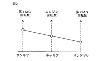
- the engine 100, the first motor generator 110, and the second motor generator 120 are connected via a power split mechanism 130 that is a planetary gear, so that the rotational speeds of the engine 100, the first motor generator 110, and the second motor generator 120 are increased. As shown in FIG. 2, the relationship is connected by a straight line in the alignment chart.
- the battery 150 is an assembled battery composed of a plurality of cells.
- the battery 150 is configured, for example, by further connecting a plurality of battery modules in which a plurality of cells are integrated in series.
- Battery 150 is, for example, a lithium ion battery.
- the voltage of the battery 150 at the time of full charge is, for example, about 200V.
- the engine 100 is controlled by an EFI (Electronic Fuel Injection) -ECU 170.
- First motor generator 110 and second motor generator 120 are controlled by MG (Motor Generator) -ECU 172.
- the EFI-ECU 170 and the MG-ECU 172 are connected so as to be capable of bidirectional communication with a PM (Power train Manager) -ECU174.
- PM Power train Manager
- PM-ECU 174 has a function of managing EFI-ECU 170 and MG-ECU 172. For example, activation (power on) and stop (power off) of EFI-ECU 170 and MG-ECU 172 are controlled by a command signal from PM-ECU 174.
- PM-ECU 174 instructs EFI-ECU 170 on the target output and target torque of engine 100, and MG-ECU 172 generates power from first motor generator 110, drive power from second motor generator 120, and the like. Is commanded. Therefore, the PM-ECU 174 corresponds to a control device that comprehensively controls the power train of the vehicle. As an example, the PM-ECU 174 determines the driving torque of the vehicle according to the amount of operation of the accelerator pedal 180 by the user (also referred to as the accelerator opening), and implements the EFI-ECU 170 and the MG- so as to realize the determined driving torque. Commands are given to the ECU 172. The accelerator opening is detected by an accelerator opening sensor 182. The starting and stopping of PM-ECU 174 is managed by power supply ECU 176.
- the power supply ECU 176 determines whether or not the user (driver) has operated the start switch 178, generates an IG on signal or an IG off signal in accordance with the operation of the start switch 178 by the user, and sends it to the PM-ECU 174 Output. As an example, the power supply ECU 176 determines whether or not the user has operated the start switch 178 based on a voltage that changes as the user operates the start switch 178. Note that, as a method for determining whether or not the user has operated the start switch 178, a general method for determining whether or not the switch has been operated may be used. Do not repeat.
- power supply ECU 176 when the user operates start switch 178 while PM-ECU 174 is stopped, power supply ECU 176 generates an IG on signal. PM-ECU 174 is activated when an IG ON signal is input from power supply ECU 176.
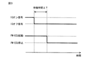
- PM-ECU 174 maintains the activated state until IG off signal is continuously input from power supply ECU 176 and input for a predetermined standby time ⁇ T, and IG off signal is continued from power supply ECU 176. If it is input for a predetermined waiting time ⁇ T or longer, it stops.
- the PM-ECU 174 can be stopped and started by operating the start switch 178 even when the vehicle is running.
- PM-ECU 174 is started when start switch 178 is operated to restart PM-ECU 174 after being stopped by operation of start switch 178.
- the driving torque of the vehicle is limited.
- the driving torque is reduced compared to a case where the driving torque is set to zero, is limited to an upper limit value or less, or the driving torque determined according to the accelerator opening is not limited.
- PM-ECU 174 releases the limitation of drive torque due to a decrease in the operation amount of accelerator pedal 180.
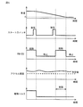
- the PM-ECU 174 stops when the start switch 178 is operated, and then when the start switch 178 is operated to restart the PM-ECU 174, the accelerator opening is equal to or greater than a predetermined value. If so, the driving torque of the vehicle is limited. When the accelerator opening becomes smaller than a predetermined value, the restriction on the driving torque is released.
- the driving torque is limited.
- the desired driving torque can be realized without operating the start switch 178 again. Therefore, it is possible to prevent the drive torque from being generated unexpectedly and to regenerate the drive torque with a small number of operations.
- the throttle opening may be used instead of the accelerator opening.
- the throttle opening may be used instead of the accelerator opening.
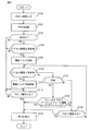
- the PM-ECU 174 is activated by the operation of the stat switch 178. However, as shown in FIG. 5, the PM-ECU 174 stops the vehicle with the accelerator opening (or the throttle opening) exceeding a predetermined value. If you do, stop. As a result, when the driver stops, the limitation of the driving torque is released by releasing the foot from the accelerator pedal 180, and the vehicle can be prevented from starting unexpectedly due to the creep torque generated as a result.
- the PM-ECU 174 may be configured to stop when the vehicle stops with the accelerator opening (or throttle opening) equal to or greater than a predetermined value and the driver leaves the vehicle.
- a parking brake (not shown) is operated so as to generate a braking force when the vehicle stops with the accelerator opening (or throttle opening) exceeding a predetermined value, or a shift lever (see FIG.
- the PM-ECU 174 may be configured to maintain the activated state when the shift position selected by the control (not shown) is the parking (P) position.
- the driver exiting the vehicle may be detected, for example, by turning off the load sensor on the driver's seat or opening the door on the driver's seat side.
- the brake pedal 180 is not operated, the parking brake is released, and the shift position is other than the parking position. If so, the PM-ECU 174 may be configured to stop.
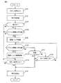
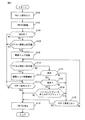
- PM-ECU 174 A process executed by PM-ECU 174 will be described with reference to FIG.
- S an IG ON signal is input in step (hereinafter abbreviated as S) 100
- PM-ECU 174 is activated in S102.
- S104 it is determined in S104 whether the vehicle is traveling. Whether or not the vehicle is traveling is determined, for example, based on whether or not the vehicle speed is greater than zero.
- the vehicle speed is detected from, for example, the rotational speed of the wheel.
- PM-ECU 174 stops when the vehicle stops with the accelerator opening being equal to or greater than a predetermined value (YES at S118) and the driver leaves the vehicle (YES at S122). You may comprise as follows.
- PM-ECU 174 may be configured to maintain the activated state without stopping.
- PM-ECU 174 may be configured to stop.
Landscapes
- Engineering & Computer Science (AREA)
- Mechanical Engineering (AREA)
- Chemical & Material Sciences (AREA)
- Combustion & Propulsion (AREA)
- Transportation (AREA)
- Automation & Control Theory (AREA)
- General Engineering & Computer Science (AREA)
- Health & Medical Sciences (AREA)
- Biomedical Technology (AREA)
- General Health & Medical Sciences (AREA)
- Control Of Vehicle Engines Or Engines For Specific Uses (AREA)
- Hybrid Electric Vehicles (AREA)
- Electrical Control Of Air Or Fuel Supplied To Internal-Combustion Engine (AREA)
- Combined Controls Of Internal Combustion Engines (AREA)
- Electric Propulsion And Braking For Vehicles (AREA)
Abstract
Description
ステップ(以下ステップをSと略す)100にて、IGオン信号が入力されると、S102にて、PM-ECU174は起動する。起動後、S104にて、車両が走行中であるかどうかが判断される。車両が走行中であるかどうかは、たとえば車速がゼロよりも大きいか否かにより判断される。車速は、たとえば車輪の回転速度等から検出される。
Claims (5)
- アクセルペダルを運転者が操作することにより走行する車両の制御システムであって、
前記車両の駆動トルクを制御する制御装置と、
前記制御装置を起動ならびに停止させるために運転者が操作するスイッチとを備え、
前記制御装置は、
前記スイッチが操作されたことによって停止した後、前記車両の走行中に前記スイッチが再び操作されると、再起動するとともに、
再起動時に前記アクセルペダルが操作されているときは、前記車両の駆動トルクを制限し、
前記アクセルペダルの操作量が低下することに起因して駆動トルクの制限を解除する、車両の制御システム。 - 前記制御装置は、
前記スイッチが操作されたことによって停止した後、前記制御装置の再起動のために前記スイッチが操作されたときに、アクセル開度またはスロットル開度が所定値以上であると、前記車両の駆動トルクを制限し、
アクセル開度またはスロットル開度が前記所定値よりも小さくなると、駆動トルクの制限を解除する、請求項1に記載の車両の制御システム。 - 前記制御装置は、アクセル開度またはスロットル開度が前記所定値以上のまま前記車両が停車した場合、停止する、請求項2に記載の車両の制御システム。
- 前記制御装置は、アクセル開度またはスロットル開度が前記所定値以上のまま前記車両が停車し、かつ運転者が前記車両から出た場合、停止する、請求項2に記載の車両の制御システム。
- 前記制御装置は、アクセル開度またはスロットル開度が前記所定値以上のまま前記車両が停車したとき、制動力を発生するようにパーキングブレーキが操作されているか、もしくはシフトポジションがパーキングポジションであると、起動した状態を維持する、請求項4に記載の車両の制御システム。
Priority Applications (4)
| Application Number | Priority Date | Filing Date | Title |
|---|---|---|---|
| CN201280077446.3A CN104822924B (zh) | 2012-12-04 | 2012-12-04 | 车辆的控制系统 |
| JP2014550822A JP5924419B2 (ja) | 2012-12-04 | 2012-12-04 | 車両の制御システム |
| US14/646,505 US9611795B2 (en) | 2012-12-04 | 2012-12-04 | Control system of vehicle |
| PCT/JP2012/081312 WO2014087474A1 (ja) | 2012-12-04 | 2012-12-04 | 車両の制御システム |
Applications Claiming Priority (1)
| Application Number | Priority Date | Filing Date | Title |
|---|---|---|---|
| PCT/JP2012/081312 WO2014087474A1 (ja) | 2012-12-04 | 2012-12-04 | 車両の制御システム |
Publications (1)
| Publication Number | Publication Date |
|---|---|
| WO2014087474A1 true WO2014087474A1 (ja) | 2014-06-12 |
Family
ID=50882925
Family Applications (1)
| Application Number | Title | Priority Date | Filing Date |
|---|---|---|---|
| PCT/JP2012/081312 Ceased WO2014087474A1 (ja) | 2012-12-04 | 2012-12-04 | 車両の制御システム |
Country Status (4)
| Country | Link |
|---|---|
| US (1) | US9611795B2 (ja) |
| JP (1) | JP5924419B2 (ja) |
| CN (1) | CN104822924B (ja) |
| WO (1) | WO2014087474A1 (ja) |
Families Citing this family (1)
| Publication number | Priority date | Publication date | Assignee | Title |
|---|---|---|---|---|
| JP6327275B2 (ja) * | 2016-03-22 | 2018-05-23 | トヨタ自動車株式会社 | 車両の変速制御装置 |
Citations (4)
| Publication number | Priority date | Publication date | Assignee | Title |
|---|---|---|---|---|
| JP2003003884A (ja) * | 2001-06-22 | 2003-01-08 | Denso Corp | 内燃機関のスロットル制御装置 |
| JP2004092623A (ja) * | 2002-09-04 | 2004-03-25 | Hitachi Unisia Automotive Ltd | 自動変速機付車両の始動制御装置 |
| JP2007154674A (ja) * | 2005-11-30 | 2007-06-21 | Toyota Motor Corp | 筒内噴射式内燃機関のスロットル制御装置 |
| JP2007224848A (ja) * | 2006-02-24 | 2007-09-06 | Toyota Motor Corp | 内燃機関の制御装置 |
Family Cites Families (7)
| Publication number | Priority date | Publication date | Assignee | Title |
|---|---|---|---|---|
| JP3633282B2 (ja) * | 1998-06-04 | 2005-03-30 | トヨタ自動車株式会社 | 車両のエンジン停止制御装置 |
| JP2003175747A (ja) * | 2001-12-13 | 2003-06-24 | Denso Corp | エンジン自動停止再始動装置 |
| JP4012893B2 (ja) * | 2004-06-11 | 2007-11-21 | トヨタ自動車株式会社 | 内燃機関の制御装置 |
| JP4811498B2 (ja) * | 2009-05-29 | 2011-11-09 | 株式会社デンソー | 車両の制御装置 |
| KR101312630B1 (ko) * | 2011-07-08 | 2013-10-04 | 에스엘 주식회사 | 차량용 램프 및 그 제어 방법 |
| GB2495511A (en) * | 2011-10-12 | 2013-04-17 | Ford Global Tech Llc | A method and system for controlling the maximum torque of an internal combustion engine |
| JP5862533B2 (ja) | 2012-09-27 | 2016-02-16 | トヨタ自動車株式会社 | 車両および車両の制御方法 |
-
2012
- 2012-12-04 US US14/646,505 patent/US9611795B2/en active Active
- 2012-12-04 JP JP2014550822A patent/JP5924419B2/ja active Active
- 2012-12-04 WO PCT/JP2012/081312 patent/WO2014087474A1/ja not_active Ceased
- 2012-12-04 CN CN201280077446.3A patent/CN104822924B/zh not_active Expired - Fee Related
Patent Citations (4)
| Publication number | Priority date | Publication date | Assignee | Title |
|---|---|---|---|---|
| JP2003003884A (ja) * | 2001-06-22 | 2003-01-08 | Denso Corp | 内燃機関のスロットル制御装置 |
| JP2004092623A (ja) * | 2002-09-04 | 2004-03-25 | Hitachi Unisia Automotive Ltd | 自動変速機付車両の始動制御装置 |
| JP2007154674A (ja) * | 2005-11-30 | 2007-06-21 | Toyota Motor Corp | 筒内噴射式内燃機関のスロットル制御装置 |
| JP2007224848A (ja) * | 2006-02-24 | 2007-09-06 | Toyota Motor Corp | 内燃機関の制御装置 |
Also Published As
| Publication number | Publication date |
|---|---|
| CN104822924B (zh) | 2017-07-28 |
| US9611795B2 (en) | 2017-04-04 |
| JPWO2014087474A1 (ja) | 2017-01-05 |
| JP5924419B2 (ja) | 2016-05-25 |
| CN104822924A (zh) | 2015-08-05 |
| US20150292427A1 (en) | 2015-10-15 |
Similar Documents
| Publication | Publication Date | Title |
|---|---|---|
| WO2014087513A1 (ja) | 動力伝達装置 | |
| JP2013183503A (ja) | 電動車両の制御装置 | |
| JP2008168720A (ja) | 自動車およびその制御方法 | |
| WO2012101802A1 (ja) | 車両および車両用制御方法 | |
| US20150142230A1 (en) | Method for a vehicle having an electric machine | |
| JP2011097666A (ja) | 自動車およびその制御方法 | |
| JP2011183847A (ja) | 車両の制御装置 | |
| KR102040633B1 (ko) | 연소 기관을 시동하기 위한 방법 및 시스템 | |
| JPWO2014087515A1 (ja) | ハイブリッド車両用駆動装置 | |
| CN103476655B (zh) | 车辆和车辆用控制方法 | |
| JP5924419B2 (ja) | 車両の制御システム | |
| JP5741068B2 (ja) | 電動車両 | |
| JP2012086801A (ja) | ハイブリッド車両の制御装置、ハイブリッド車両の制御方法 | |
| JP2018506670A (ja) | 自動車のフリーホイールモードへの自動切り替え方法 | |
| JP5920489B2 (ja) | 車両の制御システム | |
| JP2015055163A (ja) | 車両 | |
| JP5541151B2 (ja) | ハイブリッド自動車 | |
| JP5700053B2 (ja) | 車両および車両用制御方法 | |
| JP6538502B2 (ja) | 車両 | |
| JP6614052B2 (ja) | 自動車 | |
| JP5878417B2 (ja) | 車両の制御装置 | |
| JP6750359B2 (ja) | 自動車 | |
| JP6740763B2 (ja) | 自動車 | |
| JP2011251634A (ja) | ハイブリッド車の制御装置 | |
| WO2014112050A1 (ja) | 車両の制御システム |
Legal Events
| Date | Code | Title | Description |
|---|---|---|---|
| 121 | Ep: the epo has been informed by wipo that ep was designated in this application |
Ref document number: 12889529 Country of ref document: EP Kind code of ref document: A1 |
|
| ENP | Entry into the national phase |
Ref document number: 2014550822 Country of ref document: JP Kind code of ref document: A |
|
| WWE | Wipo information: entry into national phase |
Ref document number: 14646505 Country of ref document: US |
|
| NENP | Non-entry into the national phase |
Ref country code: DE |
|
| 122 | Ep: pct application non-entry in european phase |
Ref document number: 12889529 Country of ref document: EP Kind code of ref document: A1 |