WO2014080573A1 - 原料充填方法、単結晶の製造方法及び単結晶製造装置 - Google Patents
原料充填方法、単結晶の製造方法及び単結晶製造装置 Download PDFInfo
- Publication number
- WO2014080573A1 WO2014080573A1 PCT/JP2013/006344 JP2013006344W WO2014080573A1 WO 2014080573 A1 WO2014080573 A1 WO 2014080573A1 JP 2013006344 W JP2013006344 W JP 2013006344W WO 2014080573 A1 WO2014080573 A1 WO 2014080573A1
- Authority
- WO
- WIPO (PCT)
- Prior art keywords
- raw material
- quartz crucible
- single crystal
- recharge
- melt
- Prior art date
- Legal status (The legal status is an assumption and is not a legal conclusion. Google has not performed a legal analysis and makes no representation as to the accuracy of the status listed.)
- Ceased
Links
Images


Classifications
-
- C—CHEMISTRY; METALLURGY
- C30—CRYSTAL GROWTH
- C30B—SINGLE-CRYSTAL GROWTH; UNIDIRECTIONAL SOLIDIFICATION OF EUTECTIC MATERIAL OR UNIDIRECTIONAL DEMIXING OF EUTECTOID MATERIAL; REFINING BY ZONE-MELTING OF MATERIAL; PRODUCTION OF A HOMOGENEOUS POLYCRYSTALLINE MATERIAL WITH DEFINED STRUCTURE; SINGLE CRYSTALS OR HOMOGENEOUS POLYCRYSTALLINE MATERIAL WITH DEFINED STRUCTURE; AFTER-TREATMENT OF SINGLE CRYSTALS OR A HOMOGENEOUS POLYCRYSTALLINE MATERIAL WITH DEFINED STRUCTURE; APPARATUS THEREFOR
- C30B15/00—Single-crystal growth by pulling from a melt, e.g. Czochralski method
- C30B15/02—Single-crystal growth by pulling from a melt, e.g. Czochralski method adding crystallising materials or reactants forming it in situ to the melt
-
- C—CHEMISTRY; METALLURGY
- C30—CRYSTAL GROWTH
- C30B—SINGLE-CRYSTAL GROWTH; UNIDIRECTIONAL SOLIDIFICATION OF EUTECTIC MATERIAL OR UNIDIRECTIONAL DEMIXING OF EUTECTOID MATERIAL; REFINING BY ZONE-MELTING OF MATERIAL; PRODUCTION OF A HOMOGENEOUS POLYCRYSTALLINE MATERIAL WITH DEFINED STRUCTURE; SINGLE CRYSTALS OR HOMOGENEOUS POLYCRYSTALLINE MATERIAL WITH DEFINED STRUCTURE; AFTER-TREATMENT OF SINGLE CRYSTALS OR A HOMOGENEOUS POLYCRYSTALLINE MATERIAL WITH DEFINED STRUCTURE; APPARATUS THEREFOR
- C30B29/00—Single crystals or homogeneous polycrystalline material with defined structure characterised by the material or by their shape
- C30B29/02—Elements
- C30B29/06—Silicon
-
- Y—GENERAL TAGGING OF NEW TECHNOLOGICAL DEVELOPMENTS; GENERAL TAGGING OF CROSS-SECTIONAL TECHNOLOGIES SPANNING OVER SEVERAL SECTIONS OF THE IPC; TECHNICAL SUBJECTS COVERED BY FORMER USPC CROSS-REFERENCE ART COLLECTIONS [XRACs] AND DIGESTS
- Y10—TECHNICAL SUBJECTS COVERED BY FORMER USPC
- Y10T—TECHNICAL SUBJECTS COVERED BY FORMER US CLASSIFICATION
- Y10T117/00—Single-crystal, oriented-crystal, and epitaxy growth processes; non-coating apparatus therefor
- Y10T117/10—Apparatus
- Y10T117/1024—Apparatus for crystallization from liquid or supercritical state
- Y10T117/1032—Seed pulling
- Y10T117/1056—Seed pulling including details of precursor replenishment
Definitions
- the present invention relates to a method of filling a raw material into a quartz crucible using a recharge tube in the production of a single crystal.
- a CZ (Czochralski) method and a MCZ (magnetic field applied Czochralski) method for applying a magnetic field are generally used.
- CZ / MCZ methods a silicon raw material is filled in a quartz crucible and melted, a seed crystal is deposited in the melt, and then pulled up to grow a silicon single crystal.
- a CZ / MCZ single crystal manufacturing apparatus pulseling machine
- a heater for heating a melt is installed in a main chamber, and a quartz crucible for storing the melt is installed inside the heater.
- raw materials are first packed in this quartz crucible, and the raw materials are melted by heating with a heater.
- the raw materials are filled in a recharge tube having a conical cone (conical valve) at the lower end, and the raw material is charged into the quartz crucible through the recharge tube. Then, after all these raw materials are melted, the growth of the silicon single crystal is started.
- the quartz crucible is filled with a melt in which raw materials are dissolved, from which a silicon single crystal is grown.
- the grown single crystal is accommodated in a pulling chamber connected to the upper part of the main chamber via a gate valve and cooled. Thereafter, the single crystal is taken out from the pulling chamber.
- Patent Document 1 As a recharging method, a rod recharging method and a method of supplying from a raw material tank as disclosed in Patent Document 1 have been proposed for a long time.
- the technique taken up in many patent documents is a method in which a raw material is stored in a recharge tube having a conical valve at the lower end, and the raw material stored in the recharge tube is put into a quartz crucible.
- Patent Documents 2 and 3 disclose the basics of this technology.
- the recharge pipe containing the raw material is hung with a wire and attached, and the internal pressure of the pulling chamber in the pulling chamber is reduced by evacuation.
- the gate valve is opened and the recharge pipe is lowered, and then the conical valve is lowered to open the opening of the recharge pipe and feed the raw material.
- the raw material to be filled as described above is usually a polycrystal or rarely a single crystal, and those which are crushed are used, and there are voids when packed in a recharge tube. Therefore, in order to add a raw material corresponding to the amount of grown single crystals, there is a case where it is insufficient to make a single charge through a recharge tube. In such a case, a plurality of inputs are continuously performed.
- Patent Document 3 a recharge pipe whose main body is expanded outward toward the lower end is used to bring the surface of the remaining melt solidified into contact with the conical valve of the recharge pipe. After raising the quartz crucible and bringing the solidified surface into contact with the conical valve, the load on the suspended recharge pipe wire is loosened, the quartz crucible is lowered to lower the conical valve, and the raw material is filled.
- the raw materials are charged by this method, the raw materials may not come out uniformly and gather in the center, and the variation in the unmelted raw material height may increase. Therefore, after waiting until the raw material previously charged has melted to some extent, the next raw material is charged, or even if all the raw materials are successfully charged, it takes time to melt the raw material. There is a problem that it takes time.
- the present invention has been made in view of the above-described problems, and provides a raw material filling method capable of smoothly feeding a raw material into a crucible, shortening a melting time, and suppressing damage to a quartz crucible and a recharge tube.
- the purpose is to do.
- a step of filling a raw material into a quartz crucible a step of melting the raw material in the quartz crucible to form a melt, and a single crystal from the melt
- a conical valve for opening and closing a quartz cylindrical member containing the raw material and a lower end opening of the cylindrical member in the step of filling the raw material into the quartz crucible in the production of a single crystal having a pulling step
- the raw material is stored in a recharge pipe having the above structure, the recharge pipe containing the raw material is set in a chamber, the conical valve is lowered, and an opening at the lower end of the cylindrical member is opened into the quartz crucible.
- a raw material filling method for charging a raw material accommodated in the recharge tube wherein a distance between a lower end of the recharge tube and a raw material or a melt in the quartz crucible at the start of charging of the raw material is 20
- the recharge pipe and the quartz crucible are arranged so as to be not less than 250 mm and not more than 250 mm, and then the ratio (CL / (SL) is 1.3 or more and 1.45 or less, and the raw material charging method is provided, wherein the raw material is charged while simultaneously lowering the quartz crucible and the conical valve of the recharge pipe. .
- the recharge tube and the quartz crucible can be placed at an appropriate position and then the raw material can be charged at an appropriate charging speed, so that the quartz crucible is damaged by the falling raw material or the recharge tube and It is possible to suppress damage to the recharge tube due to interference with the charged raw material. Moreover, the upper surface of the charged raw material becomes flat, and subsequent melting can be performed efficiently.
- the descending speed (SL) of the conical valve of the recharge pipe is 250 mm / min or more and 375 mm / min or less.
- the descending speed (SL) is 250 mm / min or more, it is possible to prevent the raw material from being charged intermittently and prevent the charging time from increasing, and the raw material can be reliably and uniformly charged into the quartz crucible. Thereby, it is possible to reduce the melting time of the raw material and the waiting time until the next charging when continuously charging.
- the descending speed (SL) is 375 mm / min or less, it is possible to more reliably suppress the raw material from being vigorously charged and damaging the quartz crucible.
- the step of filling the quartz crucible with the raw material the step of melting the raw material in the quartz crucible to form a melt, and the step of pulling up the single crystal from the melt are repeated.
- a quartz crucible for containing a raw material, a chamber for storing a heater for melting the raw material into a melt, and a quartz cylindrical member set in the chamber for containing the raw material And a recharge pipe having a conical valve for opening and closing the opening at the lower end of the cylindrical member, wherein the quartz crucible in the raw material filling method of the present invention is filled with the raw material And a controller for automatically controlling the arrangement of the recharge pipe and the quartz crucible at the start of charging of the raw material, and the lowering of the conical valve of the quartz crucible and the recharge pipe during the charging of the raw material.
- An apparatus for producing a single crystal is provided.
- the recharge tube and the quartz crucible can be controlled in a short period of time, and the above-described raw material filling method can be reliably performed. It becomes that. Thereby, the productivity of single crystal production can be improved.
- the distance between the lower end of the recharge tube and the raw material or melt in the quartz crucible is set to 200 mm or more and 250 mm or less at the start of charging of the raw material. Since the ratio (CL / SL) of the descending speed (CL) of the quartz crucible and the descending speed (SL) of the conical valve of the recharge tube is 1.3 or more and 1.45 or less, the recharge tube and the quartz crucible The raw material can be charged at an appropriate charging speed after being placed in an appropriate position, and the quartz crucible is damaged by the falling raw material, or the recharge tube and the charged raw material interfere with each other so that the recharge tube is damaged.
- the operation time variation by the operator is reduced, and stable operation is possible.
- the descending speed (SL) of the conical valve is set to 250 mm / min or more and 375 mm / min or less, the raw material can be reliably and uniformly charged into the quartz crucible. Thereby, it is possible to reduce the melting time of the raw material and the waiting time until the next charging when continuously charging.
- FIG. 3 is a diagram showing an outline of a quartz crucible used in Example 1-2 and Comparative Example 1-2. It is a figure which shows the result of Example 1 and Comparative Example 1.
- the single crystal manufacturing apparatus 20 is arranged around a main chamber 1, a quartz crucible 9 and a graphite crucible 10 that contain a melt 8 in the main chamber 1, and a quartz crucible 9 and a graphite crucible 10.
- a recharge tube 4 a recharge tube 4.
- the pull chamber 2 is provided with a gas inlet 14 for introducing a gas circulated in the furnace, and a gas outlet 15 for discharging the gas circulated in the furnace is provided at the bottom of the main chamber 1.
- the quartz crucible 9 and the graphite crucible 10 are installed via a support shaft 13 and can be moved up and down in the direction of the crystal growth axis, and the quartz crucible is made up to compensate for the liquid level drop of the melt 8 that has been crystallized and reduced during crystal growth. 9 and the graphite crucible 10 are raised. Thereby, the height of the liquid surface of the melt 8 is kept substantially constant.
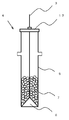
- the recharge pipe 4 includes a quartz cylindrical member 5 that accommodates a raw material (polycrystalline or single crystal) 7, and a conical valve 6 for opening and closing an opening at the lower end of the cylindrical member 5.
- the recharge tube lid 17 is attached to the upper end of the cylindrical member 5.
- the raw material 7 accommodated in the recharge pipe 4 lowers the power of the heater 12 and solidifies the surface of the melt 8 in the quartz crucible 9, and then lowers the conical valve 6 to open the opening as shown in FIG. By opening, the raw material 7 can be put into the quartz crucible 9.
- the recharge tube 4 is set by suspending the wire 3 in the pull chamber 2 when the raw material is charged, and is removed when the single crystal is manufactured after the raw material is charged.
- the tip of the wire 3 is fixed to the conical valve 6 of the recharge pipe 4, and the conical valve 6 can be lowered by sending the wire 3 downward.
- the single crystal manufacturing apparatus 20 of the present invention further includes the recharge tube 4 and the quartz crucible 9 at the start of charging the raw material 7 in the step of filling the raw material into the quartz crucible in the raw material filling method of the present invention described in detail below.
- a control device 18 is provided for automatically controlling the arrangement position and the descending speed of the quartz crucible 9 and the conical valve 6 of the recharge pipe 4 while the raw material 7 is being charged.
- the control device 18 can reliably control the recharge tube 4 and the quartz crucible 9 in a short time, thereby improving productivity and saving labor.
- a laser measuring sensor or a camera for detecting the melt surface in the quartz crucible 9 and the position of the charged raw material can be provided.
- the method for producing a single crystal of the present invention includes a step of filling a raw material 7 in a quartz crucible 9, a step of melting the raw material 7 in the quartz crucible 9 to form a melt 8, and a single crystal from the melt 8. This is a method for producing a plurality of single crystals using the same quartz crucible 9 by repeating the pulling process.
- the raw material filling method of the present invention is a method in which the raw material 7 accommodated in the recharge tube 4 is put into the quartz crucible 9 in the step of filling the raw material 7 into the quartz crucible 9 in the production of the single crystal of the present invention. is there.
- the raw material 7 is filled into the quartz crucible 9 by the raw material filling method of the present invention.
- the raw material 7 is accommodated in the recharge pipe 4.
- the recharge tube 4 containing the raw material 7 is suspended and set in the pull chamber 2 by the wire 3.
- the distance between the lower end of the recharge tube 4 and the raw material or melt 8 in the quartz crucible 9 at the start of charging the raw material 7 is The recharge tube 4 and the quartz crucible 9 are arranged so as to be 200 mm or more and 250 mm or less. At this time, the distance can be adjusted by moving the quartz crucible 9 in the vertical direction.
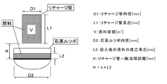
- the distance can be determined in detail within the range of 200 mm or more and 250 mm or less using the following formula (2).
- V (D1 ⁇ 10 ⁇ 3 ) 2 ⁇ ⁇ / 4 ⁇ (L1 ⁇ 10 ⁇ 3 ) (1)
- H k ⁇ L2 (2)
- L2 V / ((D2 ⁇ 10 ⁇ 3 ) 2 ⁇ ⁇ / 4)
- D1 Recharge tube inner diameter (mm)
- L1 Recharge tube length (mm)
- V Raw material volume [m 3 ]
- H Distance [mm]
- L2 Estimated height of raw material after charging [mm]
- D2 Quartz crucible inner diameter [mm]
- k is a constant determined in advance by experiments or the like. For example, k when a quartz crucible having a diameter of 800 mm is used can be set to 1.42.
- the conical valve 6 is lowered to open the opening of the cylindrical member 5, whereby the raw material 7 accommodated in the recharge pipe 4 is put into the quartz crucible 9.
- the quartz crucible is adjusted so that the ratio (CL / SL) of the descending speed (CL) of the quartz crucible 9 and the descending speed (SL) of the conical valve 6 of the recharge pipe 4 is 1.3 or more and 1.45 or less.
- 9 and the recharge pipe 4 are lowered simultaneously, and the raw material 7 is charged.
- the input can be divided into a plurality of times and the above-described raw material filling method can be repeated.
- the raw material filling method of the present invention since charging is started after the recharge tube and the quartz crucible are arranged at appropriate positions, the raw material is dispersed in the air when the position of the quartz crucible is too low, that is, the raw material
- the descending speed (CL) of the quartz crucible is made faster than the descending speed (SL) of the conical valve and the ratio (CL / SL) is set to 1.3 or more and 1.45 or less, the input amount of raw material can be reduced. Since the position of the quartz crucible can be lowered early by a corresponding amount, damage to the quartz crucible and the recharge tube can be reliably suppressed.
- the raw material filling method of the present invention can eliminate the variation in operation by the operator as in the conventional case, reduce the variation in working time, and expect stable raw material filling.
- the recharge pipe is set in the pull chamber, the gate valve is opened, the raw material is filled, the recharge pipe is pulled into the pull chamber, the gate valve is closed, and the pull chamber is closed. -A series of steps until the inside is returned to normal pressure can be automatically performed, and these controls can be performed by the control device 18 described above.
- the descending speed (SL) of the conical valve of the recharge pipe when the raw material is charged be 250 mm / min or more and 375 mm / min or less.
- the descending speed (SL) is 250 mm / min or more, it is possible to prevent the raw material from being charged intermittently and prevent the charging time from increasing, and the raw material can be reliably and uniformly charged into the quartz crucible. Thereby, it is possible to reduce the melting time of the raw material and the waiting time until the next charging when continuously charging.
- the descending speed (SL) is 375 mm / min or less, it is possible to more reliably suppress the raw material that has been vigorously charged from damaging the quartz crucible.
- the raw material 7 is melted in the quartz crucible 9 by the heater 12 to obtain a melt 8.
- a seed crystal (not shown) is brought into contact with the melt 8 to grow a single crystal while being pulled up.
- a plurality of single crystals are manufactured by repeating the steps of filling with the raw material filling method of the present invention and pulling up the single crystal using the same quartz crucible.
- the quartz crucible in the step of filling the raw material, the quartz crucible is prevented from being damaged by the falling raw material, and the recharge tube and the charged raw material are prevented from interfering with each other to prevent the recharge tube from being damaged.
- the raw material can be uniformly introduced into the quartz crucible. Therefore, the melting time of the raw material and the waiting time until the next charging when continuously charging can be reduced, and the manufacturing time of the single crystal can be reduced.
- Example 1 Using the single crystal manufacturing apparatus of the present invention as shown in FIG. 1, 75 kg of the raw material was charged into the quartz crucible according to the raw material filling method of the present invention, and the state of the dropping of the charged raw material and the uniformity of the charging were evaluated.
- the quartz crucible used had a diameter of 800 mm (32 inches).
- plate were arrange
- the collision frequency between the charged raw material and the quartz crucible and the presence / absence of interference between the charged raw material and the recharge tube were evaluated by a video by a camera. Further, as shown in FIG. 4, the uniformity of the raw material input was evaluated by measuring the difference ⁇ h between the maximum h max and the minimum h min of the height of the raw material from the virtual solidified surface with a depth gauge.
- the conditions at the time of starting raw materials were as follows. Distance H between the lower end of the recharge tube and the virtual solidified surface in the quartz crucible at the start of charging: 200 mm, 250 mm Quartz crucible descending speed (CL): 362.5 mm / min Conical valve descending speed (SL): 250 mm / min CL / SL: 1.45 In addition, the position of the virtual solidified surface was divided into three stages so that the melt amount was small (A), intermediate (B), and large (C).
- Table 1 shows the result of the dropping of the raw material.
- ⁇ in the falling state in the table indicates that there was little collision between the raw material and the quartz crucible and there was no interference between the raw material and the recharge tube, and ⁇ represents whether there was a collision between the raw material and the quartz crucible, or X indicates that there was little interference with the recharge tube, and X indicates that there were many collisions between the raw material and the quartz crucible, or there was also much interference between the raw material and the recharge tube.
- Table 1 shows that in all cases, the falling state of the raw material was good in Example 1, the collision with the quartz crucible was suppressed, and there was no interference between the raw material and the recharge tube.
- the maximum and minimum difference ⁇ h in the height of the raw material from the virtual solidified surface was also kept small, and the raw material was uniformly charged.
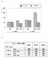
- FIG. 5B shows the results of measuring the average value and the difference between the maximum value and the minimum value of the height position (CP) of the quartz crucible before the start of charging.
- the variation in the height position (CP) of the quartz crucible is small in Example 1, while this variation is large in Comparative Example 1 described later.
- Example 2 The raw material was charged under the same conditions as in Example 1 except that the raw material was charged as follows, and evaluation was performed in the same manner as in Example 1.
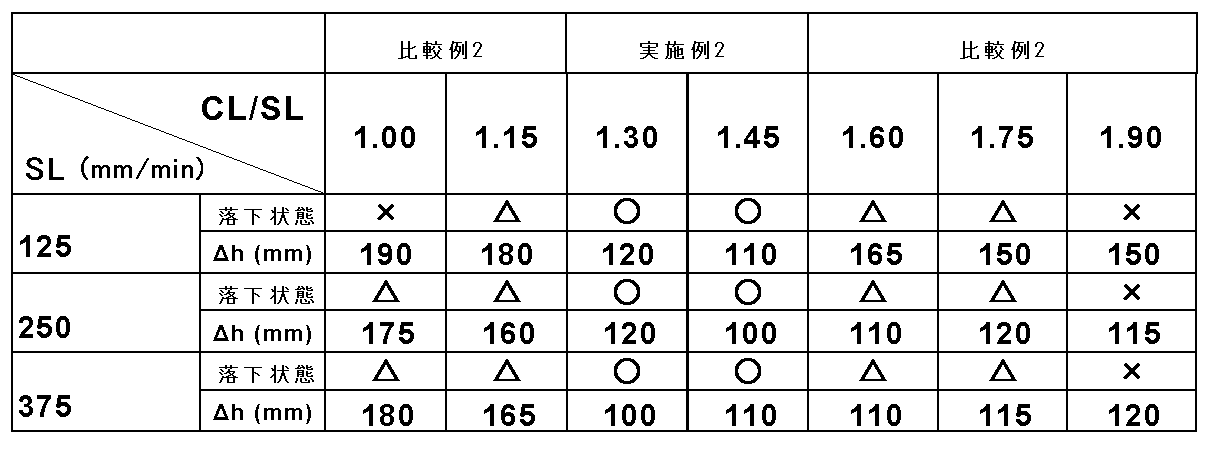
- Table 2 shows the result of the dropping of the raw material.
- Example 2 the raw material was in a good fall state, the collision with the quartz crucible was reduced, and there was no interference between the raw material and the recharge tube. Furthermore, when the descending speed of the conical valve was 250 mm / min and 375 mm / min, ⁇ h was also kept small, and the raw material was uniformly charged. On the other hand, in Comparative Example 2 to be described later, the falling state of the raw material deteriorated compared to Example 2, and the collision between the raw material and the quartz crucible and the interference between the raw material and the recharge tube increased.
- Example 1 The raw material was charged under the same conditions as in Example 1 except that the raw material was charged as follows, and evaluation was performed in the same manner as in Example 1.
- Table 1 shows the results of raw material dropping. As shown in Table 1, when the distance H is 150 mm, the conical valve gets on the raw material at the end of the raw material charging, and the recharge pipe is not damaged, but the raw material does not come out completely. The raw material input was not completed. Further, when the distance H was 300 mm and 350 mm, the raw material flew away as if it was sprayed in the air, and collided with the quartz crucible vigorously. Thus, when the damage given to a quartz crucible is large, since there is a case where the worst case leaks, it is not preferable.
- Example 1 Except that the distance was set to 300 mm, 225 kg of the raw material was divided into three times (75 kg once), and the time from the start to the end of each divided raw material was measured in the same manner as in Example 1. This was repeated (data number 93), and the average value and the difference between the maximum value and the minimum value were evaluated. As a result, as shown in FIGS. 5A and 5B, both the process time variation and the quartz crucible height position (CP) variation were worse than those of Example 1.
- the present invention is not limited to the above embodiment.
- the above-described embodiment is an exemplification, and the present invention has any configuration that has substantially the same configuration as the technical idea described in the claims of the present invention and that exhibits the same effects. Are included in the technical scope.
Landscapes
- Chemical & Material Sciences (AREA)
- Engineering & Computer Science (AREA)
- Crystallography & Structural Chemistry (AREA)
- Materials Engineering (AREA)
- Metallurgy (AREA)
- Organic Chemistry (AREA)
- Crystals, And After-Treatments Of Crystals (AREA)
Abstract
Description
しかし、この方法で原料を投入すると原料が均一に出ず中央部に集まり、未溶融原料高さのばらつきが大きくなることがある。そのため、前に投入した原料がある程度溶けるまで待ってから次の原料投入を行ったり、うまく全原料を投入できたとしても原料の溶融に時間がかかったりし、何れにしても追加原料の溶融に時間がかかるという問題がある。
このように下降速度(SL)が250mm/min以上であれば、原料の投入が断続的となって投入時間が増加するのを抑制でき、原料を石英ルツボ内に確実に均一に投入できる。これにより、原料の溶融時間や連続投入する際の次の投入までの待ち時間を低減できる。また、下降速度(SL)が375mm/min以下であれば、原料が勢いよく投入されて石英ルツボを破損してしまうのをより確実に抑制できる。
また、円錐バルブの下降速度(SL)を250mm/min以上、375mm/min以下とすれば、原料を石英ルツボ内に確実に均一に投入できる。これにより、原料の溶融時間や連続投入する際の次の投入までの待ち時間を低減できる。
図1に示すように、単結晶製造装置20は、メインチャンバー1と、メインチャンバー1内で融液8を収容する石英ルツボ9及び黒鉛ルツボ10と、石英ルツボ9及び黒鉛ルツボ10の周囲に配置されたヒーター12と、ヒーター12の外側周囲の断熱部材11と、メインチャンバー1の上部にゲートバルブ16を介して連設され、育成した単結晶(単結晶インゴット)を収納するプルチャンバー2と、リチャージ管4とを備えている。
本発明の単結晶の製造方法は、石英ルツボ9内に原料7を充填する工程と、石英ルツボ9内で原料7を溶融して融液8とする工程と、該融液8から単結晶を引き上げる工程とを繰り返し、同一の石英ルツボ9を用いて複数の単結晶を製造する方法である。また、本発明の原料充填方法は、本発明の単結晶の製造における石英ルツボ9内に原料7を充填する工程において、石英ルツボ9内にリチャージ管4内に収容した原料7を投入する方法である。
V=(D1×10-3)2×π/4×(L1×10-3) (1)
H=k×L2 (2)
L2=V/((D2×10-3)2×π/4) (3)
D1:リチャージ管内径(mm)
L1:リチャージ管長さ(mm)
V:原料容積[m3]
H:距離[mm]
L2:投入後の原料の推定高さ[mm]
D2:石英ルツボ内径[mm]
ここで、kは予め実験等で定められた定数である。例えば、直径800mmの石英ルツボを用いた場合のkを1.42とすることができる。
全ての原料を1度に投入できない場合には、投入を複数に分け、上記の原料充填方法を繰り返し行うようにすることができる。
このように下降速度(SL)が250mm/min以上であれば、原料の投入が断続的となって投入時間が増加するのを抑制でき、原料を石英ルツボ内に確実に均一に投入できる。これにより、原料の溶融時間や連続投入する際の次の投入までの待ち時間を低減できる。また、下降速度(SL)が375mm/min以下であれば、勢いよく投入された原料が石英ルツボを破損してしまうのをより確実に抑制できる。
このような本発明の単結晶の製造方法では、原料を充填する工程において、落下する原料によって石英ルツボが破損したり、リチャージ管と投入した原料とが干渉してリチャージ管が破損することを抑制しつつ、原料を石英ルツボ内に均一に投入できる。そのため、原料の溶融時間や連続投入する際の次の投入までの待ち時間を低減でき、単結晶の製造時間を低減できる。
図1に示すような本発明の単結晶製造装置を用い、本発明の原料充填方法に従って原料75kgを石英ルツボ内に投入し、投入された原料の落下の様子及び投入の均一さについて評価した。使用した石英ルツボは直径800mm(32インチ)のものとした。また、図4に示すように、石英ルツボの内部に嵩上げ用原料、クッション材、板をこの順に配置して仮想固化面を作り、ルツボ冷間時の条件で原料を投入した。ここで、原料の落下の様子は、投入された原料と石英ルツボとの衝突頻度と、投入された原料とリチャージ管との干渉の有無をカメラによる動画によって評価した。また、図4に示すように、原料の投入の均一さは、仮想固化面からの原料の高さの最大hmaxと最小hminの差Δhをデプスゲージにて測定することにより評価した。
投入開始時のリチャージ管の下端と石英ルツボ内の仮想固化面との距離H:200mm、250mm
石英ルツボの下降速度(CL):362.5mm/min
円錐バルブの下降速度(SL):250mm/min
CL/SL:1.45
また、仮想固化面の位置を、融液の量が少ない(A)、中間(B)、多い(C)状態となるように3段階に分けて実施した。
表1に示すように、実施例1ではいずれの場合も原料の落下状態は良好で、石英ルツボとの衝突は少なく抑えられ、原料とリチャージ管との干渉は無かった。また、仮想固化面からの原料の高さの最大と最小の差Δhも小さく抑えられ、原料が均一に投入されていた。
原料の投入時の条件は以下のようにした以外、実施例1と同じ条件で原料を投入し、実施例1と同様に評価した。
投入開始時のリチャージ管の下端と石英ルツボ内の仮想固化面との距離H:200mm
円錐バルブの下降速度(SL):125mm/min、250mm/min、375mm/min
CL/SL:1.3、1.45
尚、距離Hの200mmは、実施例1での結果が一番良かった条件である。
これに対し、後述する比較例2では原料の落下状態が実施例2と比べ悪化し、原料と石英ルツボとの衝突や原料とリチャージ管との干渉が増加していた。
原料の投入時の条件は以下のようにした以外、実施例1と同じ条件で原料を投入し、実施例1と同様に評価した。
投入開始時のリチャージ管の下端と石英ルツボ内の仮想固化面との距離H:150mm、300mm、350mm
原料の投入時の条件は以下のようにした以外、実施例2と同じ条件で原料を投入し、実施例2と同様に評価した。
CL/SL:1.0、1.15、1.60、1.75、1.90

Claims (4)
- 石英ルツボ内に原料を充填する工程と、前記石英ルツボ内で前記原料を溶融して融液とする工程と、該融液から単結晶を引き上げる工程とを有する単結晶の製造における、前記石英ルツボ内に原料を充填する工程において、前記原料を収容する石英製の円筒部材と、該円筒部材の下端の開口部を開閉するための円錐バルブとを有するリチャージ管に前記原料を収容し、該原料を収容したリチャージ管をチャンバー内にセットし、前記円錐バルブを下降させて前記円筒部材の下端の開口部を開けることで前記石英ルツボ内に前記リチャージ管内に収容した原料を投入する原料充填方法であって、
前記原料の投入開始時に前記リチャージ管の下端と前記石英ルツボ内の原料又は融液との距離が200mm以上、250mm以下となるように、前記リチャージ管及び前記石英ルツボを配置し、その後、前記石英ルツボの下降速度(CL)と前記リチャージ管の円錐バルブの下降速度(SL)の比(CL/SL)が1.3以上、1.45以下となるように、前記石英ルツボと前記リチャージ管の円錐バルブとを同時に下降させながら前記原料を投入することを特徴とする原料充填方法。 - 前記リチャージ管の円錐バルブの下降速度(SL)を250mm/min以上、375mm/min以下とすることを特徴とする請求項1に記載の原料充填方法。
- 前記石英ルツボ内に原料を充填する工程と、前記石英ルツボ内で前記原料を溶融して融液とする工程と、該融液から単結晶を引き上げる工程とを繰り返し、同一の石英ルツボを用いて複数の単結晶を製造する方法であって、
前記原料を充填する工程において、請求項1又は請求項2に記載の原料充填方法により前記原料を充填することを特徴とする単結晶の製造方法。 - 原料を収容する石英ルツボと、該原料を溶融して融液にするヒータを格納するチャンバーと、該チャンバー内にセットされ、前記原料を収容する石英製の円筒部材と、該円筒部材の下端の開口部を開閉するための円錐バルブとを有するリチャージ管とを具備する単結晶製造装置であって、
請求項1又は請求項2に記載の原料充填方法における前記石英ルツボ内に原料を充填する工程において、前記原料の投入開始時の前記リチャージ管及び前記石英ルツボの配置と、前記原料の投入中の前記石英ルツボと前記リチャージ管の円錐バルブの下降を自動で制御する制御装置を更に具備するものであることを特徴とする単結晶製造装置。
Priority Applications (4)
| Application Number | Priority Date | Filing Date | Title |
|---|---|---|---|
| US14/428,745 US9650724B2 (en) | 2012-11-20 | 2013-10-28 | Method of charging raw material, method of manufacturing single crystals, and single crystal manufacturing apparatus |
| DE112013004748.9T DE112013004748B4 (de) | 2012-11-20 | 2013-10-28 | Verfahren zum Nachchargieren von Rohmaterial und Verfahren zum Fertigen einer Vielzahl von Einkristallen |
| KR1020157006453A KR101997600B1 (ko) | 2012-11-20 | 2013-10-28 | 원료 충전방법, 단결정의 제조방법 및 단결정 제조장치 |
| CN201380048354.7A CN104641024B (zh) | 2012-11-20 | 2013-10-28 | 原料填充方法、单晶的制造方法及单晶制造装置 |
Applications Claiming Priority (2)
| Application Number | Priority Date | Filing Date | Title |
|---|---|---|---|
| JP2012254568A JP5857945B2 (ja) | 2012-11-20 | 2012-11-20 | 原料充填方法および単結晶の製造方法 |
| JP2012-254568 | 2012-11-20 |
Publications (1)
| Publication Number | Publication Date |
|---|---|
| WO2014080573A1 true WO2014080573A1 (ja) | 2014-05-30 |
Family
ID=50775770
Family Applications (1)
| Application Number | Title | Priority Date | Filing Date |
|---|---|---|---|
| PCT/JP2013/006344 Ceased WO2014080573A1 (ja) | 2012-11-20 | 2013-10-28 | 原料充填方法、単結晶の製造方法及び単結晶製造装置 |
Country Status (6)
| Country | Link |
|---|---|
| US (1) | US9650724B2 (ja) |
| JP (1) | JP5857945B2 (ja) |
| KR (1) | KR101997600B1 (ja) |
| CN (1) | CN104641024B (ja) |
| DE (1) | DE112013004748B4 (ja) |
| WO (1) | WO2014080573A1 (ja) |
Families Citing this family (12)
| Publication number | Priority date | Publication date | Assignee | Title |
|---|---|---|---|---|
| JP6390579B2 (ja) | 2015-10-19 | 2018-09-19 | 信越半導体株式会社 | 単結晶の製造方法 |
| JP7135315B2 (ja) * | 2017-12-20 | 2022-09-13 | 株式会社Sumco | リチャージ管、原料供給装置、単結晶引き上げ装置、リチャージ管の使用方法、リチャージ方法、単結晶引き上げ方法 |
| KR102003697B1 (ko) * | 2018-01-09 | 2019-07-25 | 에스케이실트론 주식회사 | 원료 리차지 방법 및 장치 |
| JP6930435B2 (ja) * | 2018-01-17 | 2021-09-01 | 株式会社Sumco | 原料供給方法およびシリコン単結晶の製造方法 |
| KR102295546B1 (ko) * | 2019-10-22 | 2021-08-30 | 에스케이실트론 주식회사 | 원료 공급 유닛 및 이를 포함하는 실리콘 단결정 잉곳의 성장 장치 |
| CN114075693A (zh) * | 2020-08-14 | 2022-02-22 | 西安奕斯伟材料科技有限公司 | 一种二次投料的控制方法、系统及计算机存储介质 |
| KR102460012B1 (ko) | 2021-01-19 | 2022-10-28 | 에스케이실트론 주식회사 | 원료 공급 호퍼 |
| CN114395795B (zh) * | 2022-01-18 | 2023-11-24 | 晶澳(无锡)光伏科技有限公司 | 单晶炉用加料装置 |
| CN115304249B (zh) * | 2022-08-01 | 2024-09-06 | 宁夏盾源聚芯半导体科技股份有限公司 | 石英坩埚熔制前底部合成砂扬砂装置及扬砂方法 |
| US20240401226A1 (en) * | 2023-05-31 | 2024-12-05 | Globalwafers Co., Ltd. | Ingot puller apparatus including automated feed assembly for charging semiconductor material |
| CN116984617A (zh) * | 2023-08-22 | 2023-11-03 | 铜陵国传电子材料科技有限公司 | 一种自动分批加料型铜粉水雾化加工装置及加工工艺 |
| KR102775318B1 (ko) * | 2024-04-09 | 2025-03-05 | 제이에이취엔지니어링주식회사 | 호퍼필터가 구성된 호퍼장치를 이용하여 반도체 단결정 성장장치에 실리콘을 충전하는 방법 |
Citations (4)
| Publication number | Priority date | Publication date | Assignee | Title |
|---|---|---|---|---|
| JP2005001977A (ja) * | 2003-05-16 | 2005-01-06 | Sumitomo Mitsubishi Silicon Corp | チョクラルスキー法による原料供給装置および原料供給方法 |
| JP2008063205A (ja) * | 2006-09-11 | 2008-03-21 | Covalent Materials Corp | 固形状原料のリチャージ装置およびこれを用いたリチャージ方法 |
| JP2008285351A (ja) * | 2007-05-16 | 2008-11-27 | Sumco Corp | 原料供給装置及びこれを備えた単結晶引上げ装置、並びに原料供給方法 |
| JP2010083685A (ja) * | 2008-09-29 | 2010-04-15 | Kyocera Corp | 原料供給装置、単結晶製造装置および単結晶の製造方法 |
Family Cites Families (8)
| Publication number | Priority date | Publication date | Assignee | Title |
|---|---|---|---|---|
| US4036595A (en) * | 1975-11-06 | 1977-07-19 | Siltec Corporation | Continuous crystal growing furnace |
| JPS62260791A (ja) | 1986-05-08 | 1987-11-13 | Toshiba Ceramics Co Ltd | シリコン単結晶引上装置 |
| JP2640683B2 (ja) | 1988-12-12 | 1997-08-13 | 信越半導体株式会社 | 単結晶棒の引上げ装置 |
| JP2935337B2 (ja) * | 1994-11-21 | 1999-08-16 | 信越半導体株式会社 | 粒状原料の供給装置およびその供給方法 |
| WO2002068732A1 (fr) | 2001-02-28 | 2002-09-06 | Shin-Etsu Handotai Co., Ltd. | Tube de recharge pour matériau polycristallin solide, et procédé de production de monocristal au moyen de ce tube |
| US7001456B2 (en) * | 2003-05-16 | 2006-02-21 | Sumitomo Mitsubishi Silicon Corporation | Apparatus and method for supplying Crystalline materials in czochralski method |
| JP4345624B2 (ja) * | 2004-09-21 | 2009-10-14 | 株式会社Sumco | チョクラルスキー法による原料供給装置および原料供給方法 |
| JP2009263178A (ja) * | 2008-04-25 | 2009-11-12 | Sumco Corp | 単結晶育成装置および原料供給方法 |
-
2012
- 2012-11-20 JP JP2012254568A patent/JP5857945B2/ja active Active
-
2013
- 2013-10-28 CN CN201380048354.7A patent/CN104641024B/zh active Active
- 2013-10-28 US US14/428,745 patent/US9650724B2/en active Active
- 2013-10-28 WO PCT/JP2013/006344 patent/WO2014080573A1/ja not_active Ceased
- 2013-10-28 DE DE112013004748.9T patent/DE112013004748B4/de active Active
- 2013-10-28 KR KR1020157006453A patent/KR101997600B1/ko active Active
Patent Citations (4)
| Publication number | Priority date | Publication date | Assignee | Title |
|---|---|---|---|---|
| JP2005001977A (ja) * | 2003-05-16 | 2005-01-06 | Sumitomo Mitsubishi Silicon Corp | チョクラルスキー法による原料供給装置および原料供給方法 |
| JP2008063205A (ja) * | 2006-09-11 | 2008-03-21 | Covalent Materials Corp | 固形状原料のリチャージ装置およびこれを用いたリチャージ方法 |
| JP2008285351A (ja) * | 2007-05-16 | 2008-11-27 | Sumco Corp | 原料供給装置及びこれを備えた単結晶引上げ装置、並びに原料供給方法 |
| JP2010083685A (ja) * | 2008-09-29 | 2010-04-15 | Kyocera Corp | 原料供給装置、単結晶製造装置および単結晶の製造方法 |
Also Published As
| Publication number | Publication date |
|---|---|
| JP2014101254A (ja) | 2014-06-05 |
| CN104641024A (zh) | 2015-05-20 |
| KR20150086229A (ko) | 2015-07-27 |
| KR101997600B1 (ko) | 2019-07-08 |
| CN104641024B (zh) | 2017-03-08 |
| JP5857945B2 (ja) | 2016-02-10 |
| US20150233013A1 (en) | 2015-08-20 |
| DE112013004748T5 (de) | 2015-09-03 |
| DE112013004748B4 (de) | 2023-02-02 |
| US9650724B2 (en) | 2017-05-16 |
Similar Documents
| Publication | Publication Date | Title |
|---|---|---|
| JP5857945B2 (ja) | 原料充填方法および単結晶の製造方法 | |
| JP4829176B2 (ja) | 単結晶の製造方法 | |
| EP2267188A1 (en) | Single-crystal growth apparatus and raw-material supply method | |
| JP6390579B2 (ja) | 単結晶の製造方法 | |
| JP5741528B2 (ja) | 原料充填方法及び単結晶の製造方法 | |
| JP6503933B2 (ja) | シリコン融液供給装置及び方法並びにシリコン単結晶製造装置 | |
| JP2015205793A (ja) | 単結晶引き上げ方法 | |
| KR20150107241A (ko) | 잉곳 제조 방법 및 잉곳 제조 장치 | |
| JP2010018446A (ja) | 単結晶の製造方法及び単結晶引上装置 | |
| JP3953042B2 (ja) | チョクラルスキー法による原料供給装置および原料供給方法 | |
| JP2009292662A (ja) | シリコン単結晶育成における肩形成方法 | |
| US9051661B2 (en) | Silicon single crystal production method | |
| JP7184029B2 (ja) | 単結晶シリコンインゴットの製造方法 | |
| WO2019142613A1 (ja) | 原料供給方法およびシリコン単結晶の製造方法 | |
| JP4562139B2 (ja) | 単結晶引上装置及び原料シリコン充填方法 | |
| JP2004262723A (ja) | 単結晶引上装置及び単結晶引上方法 | |
| JP2017043510A (ja) | シリコン単結晶の製造方法および装置 | |
| KR101554411B1 (ko) | 잉곳성장장치 및 잉곳성장방법 | |
| JP7412276B2 (ja) | 原料シリコンの充填方法 | |
| JP2020055718A (ja) | 原料供給方法およびシリコン単結晶の製造方法 | |
| CN121781273A (zh) | 一种拉晶装置及拉晶方法 | |
| JPH07300389A (ja) | 半導体単結晶製造方法 | |
| JP2013199387A (ja) | 単結晶引上装置及び単結晶引上方法 |
Legal Events
| Date | Code | Title | Description |
|---|---|---|---|
| 121 | Ep: the epo has been informed by wipo that ep was designated in this application |
Ref document number: 13856629 Country of ref document: EP Kind code of ref document: A1 |
|
| ENP | Entry into the national phase |
Ref document number: 20157006453 Country of ref document: KR Kind code of ref document: A |
|
| WWE | Wipo information: entry into national phase |
Ref document number: 14428745 Country of ref document: US |
|
| WWE | Wipo information: entry into national phase |
Ref document number: 1120130047489 Country of ref document: DE Ref document number: 112013004748 Country of ref document: DE |
|
| 122 | Ep: pct application non-entry in european phase |
Ref document number: 13856629 Country of ref document: EP Kind code of ref document: A1 |