WO2014073701A1 - 正極活物質、リチウム電池および正極活物質の製造方法 - Google Patents
正極活物質、リチウム電池および正極活物質の製造方法 Download PDFInfo
- Publication number
- WO2014073701A1 WO2014073701A1 PCT/JP2013/080562 JP2013080562W WO2014073701A1 WO 2014073701 A1 WO2014073701 A1 WO 2014073701A1 JP 2013080562 W JP2013080562 W JP 2013080562W WO 2014073701 A1 WO2014073701 A1 WO 2014073701A1
- Authority
- WO
- WIPO (PCT)
- Prior art keywords
- positive electrode
- electrode active
- active material
- source
- spinel structure
- Prior art date
Links
Images


Classifications
-
- H—ELECTRICITY
- H01—ELECTRIC ELEMENTS
- H01M—PROCESSES OR MEANS, e.g. BATTERIES, FOR THE DIRECT CONVERSION OF CHEMICAL ENERGY INTO ELECTRICAL ENERGY
- H01M4/00—Electrodes
- H01M4/02—Electrodes composed of, or comprising, active material
- H01M4/36—Selection of substances as active materials, active masses, active liquids
- H01M4/58—Selection of substances as active materials, active masses, active liquids of inorganic compounds other than oxides or hydroxides, e.g. sulfides, selenides, tellurides, halogenides or LiCoFy; of polyanionic structures, e.g. phosphates, silicates or borates
- H01M4/5825—Oxygenated metallic salts or polyanionic structures, e.g. borates, phosphates, silicates, olivines
-
- C—CHEMISTRY; METALLURGY
- C01—INORGANIC CHEMISTRY
- C01G—COMPOUNDS CONTAINING METALS NOT COVERED BY SUBCLASSES C01D OR C01F
- C01G51/00—Compounds of cobalt
- C01G51/006—Compounds containing, besides cobalt, two or more other elements, with the exception of oxygen or hydrogen
-
- C—CHEMISTRY; METALLURGY
- C01—INORGANIC CHEMISTRY
- C01G—COMPOUNDS CONTAINING METALS NOT COVERED BY SUBCLASSES C01D OR C01F
- C01G51/00—Compounds of cobalt
- C01G51/40—Cobaltates
- C01G51/42—Cobaltates containing alkali metals, e.g. LiCoO2
- C01G51/44—Cobaltates containing alkali metals, e.g. LiCoO2 containing manganese
- C01G51/54—Cobaltates containing alkali metals, e.g. LiCoO2 containing manganese of the type [Mn2O4]-, e.g. Li(CoxMn2-x)04, Li(MyCoxMn2-x-y)O4
-
- C—CHEMISTRY; METALLURGY
- C01—INORGANIC CHEMISTRY
- C01G—COMPOUNDS CONTAINING METALS NOT COVERED BY SUBCLASSES C01D OR C01F
- C01G53/00—Compounds of nickel
- C01G53/006—Compounds containing, besides nickel, two or more other elements, with the exception of oxygen or hydrogen
-
- C—CHEMISTRY; METALLURGY
- C01—INORGANIC CHEMISTRY
- C01G—COMPOUNDS CONTAINING METALS NOT COVERED BY SUBCLASSES C01D OR C01F
- C01G53/00—Compounds of nickel
- C01G53/40—Nickelates
- C01G53/42—Nickelates containing alkali metals, e.g. LiNiO2
- C01G53/44—Nickelates containing alkali metals, e.g. LiNiO2 containing manganese
- C01G53/54—Nickelates containing alkali metals, e.g. LiNiO2 containing manganese of the type [Mn2O4]-, e.g. Li(NixMn2-x)O4, Li(MyNixMn2-x-y)O4
-
- H—ELECTRICITY
- H01—ELECTRIC ELEMENTS
- H01M—PROCESSES OR MEANS, e.g. BATTERIES, FOR THE DIRECT CONVERSION OF CHEMICAL ENERGY INTO ELECTRICAL ENERGY
- H01M10/00—Secondary cells; Manufacture thereof
- H01M10/04—Construction or manufacture in general
- H01M10/0422—Cells or battery with cylindrical casing
- H01M10/0427—Button cells
-
- H—ELECTRICITY
- H01—ELECTRIC ELEMENTS
- H01M—PROCESSES OR MEANS, e.g. BATTERIES, FOR THE DIRECT CONVERSION OF CHEMICAL ENERGY INTO ELECTRICAL ENERGY
- H01M10/00—Secondary cells; Manufacture thereof
- H01M10/05—Accumulators with non-aqueous electrolyte
- H01M10/052—Li-accumulators
-
- H—ELECTRICITY
- H01—ELECTRIC ELEMENTS
- H01M—PROCESSES OR MEANS, e.g. BATTERIES, FOR THE DIRECT CONVERSION OF CHEMICAL ENERGY INTO ELECTRICAL ENERGY
- H01M10/00—Secondary cells; Manufacture thereof
- H01M10/05—Accumulators with non-aqueous electrolyte
- H01M10/052—Li-accumulators
- H01M10/0525—Rocking-chair batteries, i.e. batteries with lithium insertion or intercalation in both electrodes; Lithium-ion batteries
-
- H—ELECTRICITY
- H01—ELECTRIC ELEMENTS
- H01M—PROCESSES OR MEANS, e.g. BATTERIES, FOR THE DIRECT CONVERSION OF CHEMICAL ENERGY INTO ELECTRICAL ENERGY
- H01M10/00—Secondary cells; Manufacture thereof
- H01M10/05—Accumulators with non-aqueous electrolyte
- H01M10/056—Accumulators with non-aqueous electrolyte characterised by the materials used as electrolytes, e.g. mixed inorganic/organic electrolytes
- H01M10/0564—Accumulators with non-aqueous electrolyte characterised by the materials used as electrolytes, e.g. mixed inorganic/organic electrolytes the electrolyte being constituted of organic materials only
- H01M10/0566—Liquid materials
- H01M10/0569—Liquid materials characterised by the solvents
-
- H—ELECTRICITY
- H01—ELECTRIC ELEMENTS
- H01M—PROCESSES OR MEANS, e.g. BATTERIES, FOR THE DIRECT CONVERSION OF CHEMICAL ENERGY INTO ELECTRICAL ENERGY
- H01M4/00—Electrodes
- H01M4/02—Electrodes composed of, or comprising, active material
- H01M4/13—Electrodes for accumulators with non-aqueous electrolyte, e.g. for lithium-accumulators; Processes of manufacture thereof
- H01M4/131—Electrodes based on mixed oxides or hydroxides, or on mixtures of oxides or hydroxides, e.g. LiCoOx
-
- H—ELECTRICITY
- H01—ELECTRIC ELEMENTS
- H01M—PROCESSES OR MEANS, e.g. BATTERIES, FOR THE DIRECT CONVERSION OF CHEMICAL ENERGY INTO ELECTRICAL ENERGY
- H01M4/00—Electrodes
- H01M4/02—Electrodes composed of, or comprising, active material
- H01M4/13—Electrodes for accumulators with non-aqueous electrolyte, e.g. for lithium-accumulators; Processes of manufacture thereof
- H01M4/136—Electrodes based on inorganic compounds other than oxides or hydroxides, e.g. sulfides, selenides, tellurides, halogenides or LiCoFy
-
- H—ELECTRICITY
- H01—ELECTRIC ELEMENTS
- H01M—PROCESSES OR MEANS, e.g. BATTERIES, FOR THE DIRECT CONVERSION OF CHEMICAL ENERGY INTO ELECTRICAL ENERGY
- H01M4/00—Electrodes
- H01M4/02—Electrodes composed of, or comprising, active material
- H01M4/13—Electrodes for accumulators with non-aqueous electrolyte, e.g. for lithium-accumulators; Processes of manufacture thereof
- H01M4/139—Processes of manufacture
- H01M4/1391—Processes of manufacture of electrodes based on mixed oxides or hydroxides, or on mixtures of oxides or hydroxides, e.g. LiCoOx
-
- H—ELECTRICITY
- H01—ELECTRIC ELEMENTS
- H01M—PROCESSES OR MEANS, e.g. BATTERIES, FOR THE DIRECT CONVERSION OF CHEMICAL ENERGY INTO ELECTRICAL ENERGY
- H01M4/00—Electrodes
- H01M4/02—Electrodes composed of, or comprising, active material
- H01M4/13—Electrodes for accumulators with non-aqueous electrolyte, e.g. for lithium-accumulators; Processes of manufacture thereof
- H01M4/139—Processes of manufacture
- H01M4/1397—Processes of manufacture of electrodes based on inorganic compounds other than oxides or hydroxides, e.g. sulfides, selenides, tellurides, halogenides or LiCoFy
-
- H—ELECTRICITY
- H01—ELECTRIC ELEMENTS
- H01M—PROCESSES OR MEANS, e.g. BATTERIES, FOR THE DIRECT CONVERSION OF CHEMICAL ENERGY INTO ELECTRICAL ENERGY
- H01M4/00—Electrodes
- H01M4/02—Electrodes composed of, or comprising, active material
- H01M4/36—Selection of substances as active materials, active masses, active liquids
- H01M4/48—Selection of substances as active materials, active masses, active liquids of inorganic oxides or hydroxides
- H01M4/52—Selection of substances as active materials, active masses, active liquids of inorganic oxides or hydroxides of nickel, cobalt or iron
- H01M4/525—Selection of substances as active materials, active masses, active liquids of inorganic oxides or hydroxides of nickel, cobalt or iron of mixed oxides or hydroxides containing iron, cobalt or nickel for inserting or intercalating light metals, e.g. LiNiO2, LiCoO2 or LiCoOxFy
-
- H—ELECTRICITY
- H01—ELECTRIC ELEMENTS
- H01M—PROCESSES OR MEANS, e.g. BATTERIES, FOR THE DIRECT CONVERSION OF CHEMICAL ENERGY INTO ELECTRICAL ENERGY
- H01M4/00—Electrodes
- H01M4/02—Electrodes composed of, or comprising, active material
- H01M4/62—Selection of inactive substances as ingredients for active masses, e.g. binders, fillers
- H01M4/621—Binders
- H01M4/622—Binders being polymers
- H01M4/623—Binders being polymers fluorinated polymers
-
- H—ELECTRICITY
- H01—ELECTRIC ELEMENTS
- H01M—PROCESSES OR MEANS, e.g. BATTERIES, FOR THE DIRECT CONVERSION OF CHEMICAL ENERGY INTO ELECTRICAL ENERGY
- H01M4/00—Electrodes
- H01M4/02—Electrodes composed of, or comprising, active material
- H01M4/62—Selection of inactive substances as ingredients for active masses, e.g. binders, fillers
- H01M4/624—Electric conductive fillers
- H01M4/625—Carbon or graphite
-
- H—ELECTRICITY
- H01—ELECTRIC ELEMENTS
- H01M—PROCESSES OR MEANS, e.g. BATTERIES, FOR THE DIRECT CONVERSION OF CHEMICAL ENERGY INTO ELECTRICAL ENERGY
- H01M4/00—Electrodes
- H01M4/02—Electrodes composed of, or comprising, active material
- H01M4/64—Carriers or collectors
- H01M4/66—Selection of materials
- H01M4/661—Metal or alloys, e.g. alloy coatings
-
- H—ELECTRICITY
- H01—ELECTRIC ELEMENTS
- H01M—PROCESSES OR MEANS, e.g. BATTERIES, FOR THE DIRECT CONVERSION OF CHEMICAL ENERGY INTO ELECTRICAL ENERGY
- H01M4/00—Electrodes
- H01M4/02—Electrodes composed of, or comprising, active material
- H01M4/64—Carriers or collectors
- H01M4/70—Carriers or collectors characterised by shape or form
- H01M4/72—Grids
- H01M4/74—Meshes or woven material; Expanded metal
-
- C—CHEMISTRY; METALLURGY
- C01—INORGANIC CHEMISTRY
- C01P—INDEXING SCHEME RELATING TO STRUCTURAL AND PHYSICAL ASPECTS OF SOLID INORGANIC COMPOUNDS
- C01P2002/00—Crystal-structural characteristics
- C01P2002/70—Crystal-structural characteristics defined by measured X-ray, neutron or electron diffraction data
- C01P2002/72—Crystal-structural characteristics defined by measured X-ray, neutron or electron diffraction data by d-values or two theta-values, e.g. as X-ray diagram
-
- C—CHEMISTRY; METALLURGY
- C01—INORGANIC CHEMISTRY
- C01P—INDEXING SCHEME RELATING TO STRUCTURAL AND PHYSICAL ASPECTS OF SOLID INORGANIC COMPOUNDS
- C01P2004/00—Particle morphology
- C01P2004/01—Particle morphology depicted by an image
- C01P2004/03—Particle morphology depicted by an image obtained by SEM
-
- C—CHEMISTRY; METALLURGY
- C01—INORGANIC CHEMISTRY
- C01P—INDEXING SCHEME RELATING TO STRUCTURAL AND PHYSICAL ASPECTS OF SOLID INORGANIC COMPOUNDS
- C01P2006/00—Physical properties of inorganic compounds
- C01P2006/40—Electric properties
-
- H—ELECTRICITY
- H01—ELECTRIC ELEMENTS
- H01M—PROCESSES OR MEANS, e.g. BATTERIES, FOR THE DIRECT CONVERSION OF CHEMICAL ENERGY INTO ELECTRICAL ENERGY
- H01M4/00—Electrodes
- H01M4/02—Electrodes composed of, or comprising, active material
- H01M2004/026—Electrodes composed of, or comprising, active material characterised by the polarity
- H01M2004/028—Positive electrodes
-
- H—ELECTRICITY
- H01—ELECTRIC ELEMENTS
- H01M—PROCESSES OR MEANS, e.g. BATTERIES, FOR THE DIRECT CONVERSION OF CHEMICAL ENERGY INTO ELECTRICAL ENERGY
- H01M2220/00—Batteries for particular applications
- H01M2220/20—Batteries in motive systems, e.g. vehicle, ship, plane
-
- H—ELECTRICITY
- H01—ELECTRIC ELEMENTS
- H01M—PROCESSES OR MEANS, e.g. BATTERIES, FOR THE DIRECT CONVERSION OF CHEMICAL ENERGY INTO ELECTRICAL ENERGY
- H01M2220/00—Batteries for particular applications
- H01M2220/30—Batteries in portable systems, e.g. mobile phone, laptop
-
- H—ELECTRICITY
- H01—ELECTRIC ELEMENTS
- H01M—PROCESSES OR MEANS, e.g. BATTERIES, FOR THE DIRECT CONVERSION OF CHEMICAL ENERGY INTO ELECTRICAL ENERGY
- H01M2300/00—Electrolytes
- H01M2300/0017—Non-aqueous electrolytes
- H01M2300/0025—Organic electrolyte
- H01M2300/0028—Organic electrolyte characterised by the solvent
- H01M2300/0037—Mixture of solvents
-
- Y—GENERAL TAGGING OF NEW TECHNOLOGICAL DEVELOPMENTS; GENERAL TAGGING OF CROSS-SECTIONAL TECHNOLOGIES SPANNING OVER SEVERAL SECTIONS OF THE IPC; TECHNICAL SUBJECTS COVERED BY FORMER USPC CROSS-REFERENCE ART COLLECTIONS [XRACs] AND DIGESTS
- Y02—TECHNOLOGIES OR APPLICATIONS FOR MITIGATION OR ADAPTATION AGAINST CLIMATE CHANGE
- Y02E—REDUCTION OF GREENHOUSE GAS [GHG] EMISSIONS, RELATED TO ENERGY GENERATION, TRANSMISSION OR DISTRIBUTION
- Y02E60/00—Enabling technologies; Technologies with a potential or indirect contribution to GHG emissions mitigation
- Y02E60/10—Energy storage using batteries
-
- Y—GENERAL TAGGING OF NEW TECHNOLOGICAL DEVELOPMENTS; GENERAL TAGGING OF CROSS-SECTIONAL TECHNOLOGIES SPANNING OVER SEVERAL SECTIONS OF THE IPC; TECHNICAL SUBJECTS COVERED BY FORMER USPC CROSS-REFERENCE ART COLLECTIONS [XRACs] AND DIGESTS
- Y02—TECHNOLOGIES OR APPLICATIONS FOR MITIGATION OR ADAPTATION AGAINST CLIMATE CHANGE
- Y02P—CLIMATE CHANGE MITIGATION TECHNOLOGIES IN THE PRODUCTION OR PROCESSING OF GOODS
- Y02P70/00—Climate change mitigation technologies in the production process for final industrial or consumer products
- Y02P70/50—Manufacturing or production processes characterised by the final manufactured product
-
- Y—GENERAL TAGGING OF NEW TECHNOLOGICAL DEVELOPMENTS; GENERAL TAGGING OF CROSS-SECTIONAL TECHNOLOGIES SPANNING OVER SEVERAL SECTIONS OF THE IPC; TECHNICAL SUBJECTS COVERED BY FORMER USPC CROSS-REFERENCE ART COLLECTIONS [XRACs] AND DIGESTS
- Y02—TECHNOLOGIES OR APPLICATIONS FOR MITIGATION OR ADAPTATION AGAINST CLIMATE CHANGE
- Y02T—CLIMATE CHANGE MITIGATION TECHNOLOGIES RELATED TO TRANSPORTATION
- Y02T10/00—Road transport of goods or passengers
- Y02T10/60—Other road transportation technologies with climate change mitigation effect
- Y02T10/70—Energy storage systems for electromobility, e.g. batteries
Definitions
- the present invention relates to a positive electrode active material that exhibits good discharge capacity.
- a lithium battery usually includes a positive electrode layer, a negative electrode layer, and an electrolyte layer formed between the positive electrode layer and the negative electrode layer.
- the positive electrode layer and the negative electrode layer usually have a positive electrode active material and a negative electrode active material, respectively.
- the active material is an important member that determines the performance of the battery, and various studies have been conducted.
- Patent Document 1 discloses a lithium battery in which a part of the positive electrode is composed of a lithium transition metal oxide having an inverse spinel structure.
- LiNiVO 4 , LiCoVO 4 , and LiCuVO 4 are disclosed as lithium transition metal oxides.
- An active material having an inverted spinel structure has a high potential and is useful as a positive electrode active material.
- an active material having an inverse spinel structure is used as the positive electrode active material, there is a problem that a sufficient discharge capacity cannot be obtained.
- the present invention has been made in view of the above circumstances, and has as its main object to provide a positive electrode active material that exhibits good discharge capacity.
- a crystal having an inverted spinel structure represented by LiM 1-x Fe x VO 4 (M is Co or Ni, x satisfies 0 ⁇ x ⁇ 1).
- a positive electrode active material having a phase.
- x preferably satisfies 0 ⁇ x ⁇ 0.3.
- the crystal phase of the reverse spinel structure represented by LiCo 1-xy Ni x Mn y VO 4 (x and y satisfy 0 ⁇ x, 0 ⁇ y, x + y ⁇ 1)
- a positive electrode active material characterized by comprising:
- a portion of Co constituting the inverse spinel structure can be replaced with Ni and Mn, whereby a positive electrode active material that exhibits a very good discharge capacity can be obtained.
- the transition metal constituting the inverse spinel structure is a ternary of Co, Ni, and Mn, whereby a positive electrode active material that exhibits a very good discharge capacity can be obtained.
- both x and y are 1/3.
- the positive electrode active material preferably has a composition of Li a Co 1-xy Ni x Mn y VO 4 (a satisfies 1 ⁇ a ⁇ 1.3).
- the present invention also provides a lithium battery comprising a positive electrode layer containing a positive electrode active material, a negative electrode layer containing a negative electrode active material, and an electrolyte layer formed between the positive electrode layer and the negative electrode layer.
- the positive electrode active material is a positive electrode active material as described above.
- a lithium battery having a good discharge capacity can be obtained by using the positive electrode active material described above.
- the Li source, the M source (M is Co or Ni), the Fe source and the V source are included in the preparation step for preparing a raw material solution dissolved or dispersed in a solvent and the raw material solution.
- a positive electrode active material having a crystal phase of an inverted spinel structure represented by LiM 1-x Fe x VO 4 (x satisfies 0 ⁇ x ⁇ 1) is obtained by removing the solvent and further performing heat treatment. And a heat treatment step.
- a method for producing a positive electrode active material is provided.
- a positive electrode active material exhibiting a good discharge capacity can be obtained by substituting part of Co or Ni constituting the inverse spinel structure with Fe.
- a Li source, a Co source, a Ni source, a Mn source, and a V source are prepared by preparing a raw material solution dissolved or dispersed in a solvent, and removing the solvent contained in the raw material solution, Further, by performing a heat treatment, a crystalline phase having an inverse spinel structure represented by LiCo 1-xy Ni x Mn y VO 4 (x and y satisfy 0 ⁇ x, 0 ⁇ y, x + y ⁇ 1) And a heat treatment step for obtaining a positive electrode active material having a positive electrode active material.
- a positive electrode active material that exhibits a very good discharge capacity can be obtained by substituting a part of Co constituting the inverse spinel structure with Ni and Mn.
- a positive electrode active material exhibiting a very good discharge capacity can be obtained by using a transition metal constituting an inverse spinel structure as a ternary of Co, Ni, and Mn.
- the positive electrode active material of the present invention has an effect of exhibiting a good discharge capacity.
- FIG. 3 is a result of XRD measurement on the positive electrode active materials obtained in Examples 1 to 6 and Comparative Examples 1 and 2.
- FIG. 3 shows the results of charge / discharge measurements on the evaluation batteries obtained in Examples 1 to 3 and Comparative Example 1. It is the result of the charging / discharging measurement with respect to the battery for evaluation obtained in Example 5 and Comparative Example 2.
- 3 is a result of charge / discharge measurement on the positive electrode active materials obtained in Examples 1 to 6 and Comparative Examples 1 and 2.
- FIG. 3 shows the results of SEM observation on the positive electrode active materials obtained in Examples 7 to 9 and Comparative Example 1. 4 is a result of XRD measurement on the positive electrode active materials obtained in Examples 7 to 9. 3 is a result of charge / discharge measurement for the batteries for evaluation obtained in Examples 7 to 9 and Comparative Example 1.
- FIG. 4 is a result of XRD measurement on the positive electrode active materials obtained in Examples 7 to 9.
- the positive electrode active material the lithium battery, and the method for producing the positive electrode active material of the present invention will be described in detail.
- A. Cathode Active Material The cathode active material of the present invention can be roughly divided into two embodiments. The method for producing the positive electrode active material of the present invention will be described separately for the first embodiment and the second embodiment.
- the positive electrode active material of the first embodiment has a reverse spinel structure represented by LiM 1-x Fe x VO 4 (M is Co or Ni, and x satisfies 0 ⁇ x ⁇ 1). It has a crystalline phase.
- LiMn 2 O 4 is known as an active material having a positive spinel structure. Based on the crystal space group perspective, LiMn 2 O 4 has a space group Fd3-m in which 8a has a Li atom, 16d has a Mn atom, and 32e has an O atom. In LiMn 2 O 4, it is considered that an octahedral tunnel having Mn at the center and O atoms at the apexes is formed, and Li ions move in the tunnel.
- LiCoVO 4 is known as an active material having an inverse spinel structure. Based on the crystal space group perspective, LiCoVO 4 is presumed to have a space group Fd3-m with V atoms at 8a, Li and Co atoms at 16d, and O atoms at 32e. In LiCoVO 4, it is presumed that a tunnel suitable for the movement of Li ions is not formed. Thus, the Li atom in the reverse spinel structure exists at a site different from that of the normal spinel structure, and the reverse spinel structure does not form a tunnel suitable for the movement of Li ions. It is considered that a sufficient discharge capacity could not be exhibited.
- the positive electrode active material of the first embodiment can exhibit a good discharge capacity
- the shape of the tunnel is probably suitable for the movement (diffusion) of Li ions. This is thought to be due to the change in shape.
- transition metal V, Co, Cu, etc.
- the shape of the tunnel in which Li ions move is It cannot be changed.
- the discharge capacity is improved by the effect peculiar to the Fe element.
- the positive electrode active material of the first embodiment has a crystal phase of an inverted spinel structure represented by LiM 1-x Fe x VO 4 (M is Co or Ni, and x satisfies 0 ⁇ x ⁇ 1). .
- M is Co or Ni, and x satisfies 0 ⁇ x ⁇ 1).
- the presence of the crystal phase having the reverse spinel structure can be confirmed by, for example, X-ray diffraction (XRD) measurement.
- XRD X-ray diffraction
- the peak position may be back and forth within a range of ⁇ 1 °.
- the value of x is preferably 0.3 or less, for example, and more preferably 0.25 or less. This is because if the value of x is too large, the proportion of other crystal phases may increase.
- the value of x is usually larger than 0, preferably 0.05 or more, and more preferably 0.1 or more. This is because if the value of x is too small, the discharge capacity may not be improved.
- the positive electrode active material of the first embodiment may have at least the crystal phase of the above-described reverse spinel structure, but preferably has as the main phase. “Having as a main phase” means that the ratio of the crystal phase having the reverse spinel structure is the largest with respect to the total crystal phase contained in the positive electrode active material. Furthermore, the proportion of the crystal phase having the above inverted spinel structure is preferably, for example, 50 mol% or more, more preferably 70 mol% or more, and further preferably 90 mol% or more. This is because the discharge capacity can be further improved.
- the positive electrode active material of the first embodiment preferably has the above-described reverse spinel structure crystal phase as a single phase. In addition, the ratio of the crystal phase of the said reverse spinel structure can be confirmed by Rietveld analysis.
- the positive electrode active material of the first embodiment preferably has a composition of Li a M 1-x Fe x VO 4 .
- x is the same as described above.
- the value of a is preferably 0.8 or more, and more preferably 0.9 or more. This is because if the value of a is too small, a sufficient discharge capacity may not be obtained.
- the value of a is preferably 1.2 or less, for example, and more preferably 1.1 or less. This is because if the value of a is too large, a sufficient discharge capacity may not be obtained.
- the operating potential of the positive electrode active material is preferably 4 V or more, for example, on the basis of lithium.
- the shape of the positive electrode active material of the first embodiment is not particularly limited, and examples thereof include particles and thin films.
- the average particle diameter (D 50 ) is not particularly limited, but is, for example, in the range of 1 nm to 100 ⁇ m and in the range of 10 nm to 30 ⁇ m. It is preferable.
- the method for producing the positive electrode active material of the first embodiment is not particularly limited, and examples thereof include the method described in “C. Method for producing positive electrode active material 1. First embodiment” described later. be able to.
- the positive electrode active material of the second embodiment is represented by LiCo 1-xy Ni x Mn y VO 4 (x and y satisfy 0 ⁇ x, 0 ⁇ y, x + y ⁇ 1) It has a crystal phase having an inverse spinel structure.
- the transition metal constituting the inverse spinel structure is a ternary of Co, Ni, and Mn, whereby a positive electrode active material that exhibits a very good discharge capacity can be obtained.
- LiCoVO 4 which is an active material having an inverse spinel structure
- Li atoms and Co atoms are present at the same site. For this reason, Li is difficult to insert and desorb, and conventionally, the initial capacity was only half or less of the theoretical capacity.
- the second embodiment as described in the examples described later, by disposing specific metals (Co, Ni, Mn) having different ionic radii at the transition metal sites in the reverse spinel structure, It is considered that the ion diffusion path is changed, Li is easily inserted and desorbed, and the discharge capacity is dramatically improved.
- a tunnel suitable for the movement of Li ions is formed in the crystal phase of the inverse spinel structure.
- the positive electrode active material of the second embodiment is a reverse spinel structure represented by LiCo 1-xy Ni x Mn y VO 4 (x and y satisfy 0 ⁇ x, 0 ⁇ y, x + y ⁇ 1) Having a crystalline phase of
- the presence of the crystal phase having the reverse spinel structure can be confirmed by, for example, X-ray diffraction (XRD) measurement.
- the value of x is, for example, 0.05 or more, and preferably 0.1 or more.
- the value of x is, for example, 0.9 or less, preferably 0.8 or less, more preferably 0.5 or less, and particularly preferably 0.4 or less.
- the value of y is, for example, 0.05 or more, and preferably 0.1 or more.
- the value of y is, for example, 0.9 or less, preferably 0.8 or less, more preferably 0.5 or less, and particularly preferably 0.4 or less.
- y is preferably 0.5 or less.
- the above (1-xy) defines the ratio of Co.
- the value of (1-xy) is, for example, 0.1 or more, and preferably 0.2 or more.
- the value of (1-xy) is, for example, 0.9 or less, preferably 0.8 or less, more preferably 0.5 or less, and 0.4 or less. Is particularly preferred.
- the crystal phase is preferably a LiCo 1/3 Ni 1/3 Mn 1/3 VO 4 crystal phase.
- the positive electrode active material of the second embodiment may have at least the crystal phase having the above-described reverse spinel structure, but preferably has as the main phase. “Having as a main phase” means that the ratio of the crystal phase having the reverse spinel structure is the largest with respect to the total crystal phase contained in the positive electrode active material. Furthermore, the proportion of the crystal phase having the above inverted spinel structure is preferably, for example, 50 mol% or more, more preferably 70 mol% or more, and further preferably 90 mol% or more. This is because the discharge capacity can be further improved.
- the positive electrode active material according to the second embodiment preferably has the above-described reverse spinel structure crystal phase as a single phase. In addition, the ratio of the crystal phase of the said reverse spinel structure can be confirmed by Rietveld analysis.
- the positive electrode active material of the second embodiment preferably has a composition of Li a Co 1-xy Ni x Mn y VO 4 .
- x and y are the same as described above.
- the value of a is preferably 0.8 or more, more preferably 0.9 or more, and further preferably 1 or more. This is because if the value of a is too small, a sufficient discharge capacity may not be obtained.
- the value of a is preferably 1.5 or less, for example, and more preferably 1.3 or less. This is because if the value of a is too large, a sufficient discharge capacity may not be obtained.
- the operating potential of the positive electrode active material is preferably 4 V or more, for example, on the basis of lithium.
- the shape of the positive electrode active material of the second embodiment is not particularly limited, and examples thereof include particles and thin films.
- the average particle diameter (D 50 ) is not particularly limited, but is, for example, in the range of 1 nm to 100 ⁇ m and in the range of 10 nm to 30 ⁇ m. It is preferable.
- the method for producing the positive electrode active material of the second embodiment is not particularly limited, and examples thereof include the method described in “C. Method for producing positive electrode active material 2. Second embodiment” described later. be able to.
- the lithium battery of the present invention is a lithium battery having a positive electrode layer containing a positive electrode active material, a negative electrode layer containing a negative electrode active material, and an electrolyte layer formed between the positive electrode layer and the negative electrode layer.
- the positive electrode active material is the positive electrode active material described above.
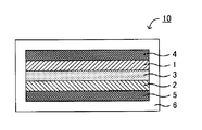
- FIG. 1 is a schematic sectional view showing an example of the lithium battery of the present invention.
- a lithium battery 10 shown in FIG. 1 includes a positive electrode layer 1, a negative electrode layer 2, an electrolyte layer 3 formed between the positive electrode layer 1 and the negative electrode layer 2, and a positive electrode current collector that collects current from the positive electrode layer 1. 4, a negative electrode current collector 5 that collects current from the negative electrode layer 2, and a battery case 6 that houses these members.
- the electrolyte layer 3 when the electrolyte layer 3 is composed of a liquid electrolyte, the electrolyte layer 3 may include a separator.
- the electrolyte layer 3 is composed of a solid electrolyte, the electrolyte layer 3 usually does not need to include a separator.
- the lithium battery of the present invention is characterized in that the positive electrode active material contained in the positive electrode layer 2 is the positive electrode active material described above.
- a lithium battery having a good discharge capacity can be obtained by using the positive electrode active material described above.
- the lithium battery of the present invention will be described for each configuration.
- Positive electrode layer is a layer containing at least a positive electrode active material. Moreover, the positive electrode layer may contain at least one of a conductive material, a binder, and a solid electrolyte material in addition to the positive electrode active material. About the positive electrode active material in this invention, it is the same as that of the content described in the said "A. positive electrode active material”.
- Examples of the conductive material include a carbon material.
- specific examples of the carbon material include acetylene black, ketjen black, carbon black, coke, carbon fiber, and graphite.
- Examples of the binder material include fluorine-based binders such as polyvinylidene fluoride (PVDF) and polytetrafluoroethylene (PTFE), and rubber-based binders such as styrene-butadiene rubber. it can.
- Examples of the solid electrolyte material include the solid electrolyte material described in “3. Electrolyte layer”.
- the content of the positive electrode active material in the positive electrode layer is preferably larger from the viewpoint of capacity, for example, preferably in the range of 60 wt% to 99 wt%, particularly preferably in the range of 70 wt% to 95 wt%. .
- the content of the conductive material is preferably smaller as long as the desired electronic conductivity can be ensured, and is preferably in the range of 1 wt% to 30 wt%, for example.
- the thickness of the positive electrode layer varies greatly depending on the configuration of the lithium battery, but is preferably in the range of 0.1 ⁇ m to 1000 ⁇ m, for example.
- Negative electrode layer is a layer containing at least a negative electrode active material.
- the negative electrode layer may contain at least one of a conductive material, a binder, and a solid electrolyte material in addition to the negative electrode active material.
- negative electrode active materials include metal active materials such as In, Al, Si, and Sn, and carbon active materials such as mesocarbon microbeads (MCMB), highly oriented graphite (HOPG), hard carbon, and soft carbon. Can do.
- MCMB mesocarbon microbeads
- HOPG highly oriented graphite
- hard carbon and soft carbon.
- soft carbon such as mesocarbon microbeads
- the types and ratios of the conductive material, the binder, and the solid electrolyte material used for the negative electrode layer are the same as those described for the positive electrode layer.
- the content of the negative electrode active material in the negative electrode layer is preferably higher from the viewpoint of capacity, for example, preferably in the range of 60 wt% to 99 wt%, and more preferably in the range of 70 wt% to 95 wt%. .
- the thickness of the negative electrode layer varies greatly depending on the configuration of the lithium battery, but is preferably in the range of 0.1 ⁇ m to 1000 ⁇ m, for example.
- Electrolyte layer The electrolyte layer in the present invention is a layer formed between the positive electrode layer and the negative electrode layer. Ion conduction between the positive electrode active material and the negative electrode active material is performed through the electrolyte layer.
- the form of the electrolyte layer is not particularly limited, and examples thereof include a liquid electrolyte layer, a gel electrolyte layer, and a solid electrolyte layer.
- the liquid electrolyte layer is preferably a layer using a non-aqueous electrolyte.
- the non-aqueous electrolyte usually contains a lithium salt and a non-aqueous solvent.
- the lithium salt include inorganic lithium salts such as LiPF 6 , LiBF 4 , LiClO 4 , LiAsF 6 , and LiCF 3 SO 3 , LiN (CF 3 SO 2 ) 2 , LiN (C 2 F 5 SO 2 ) 2 , LiC An organic lithium salt such as (CF 3 SO 2 ) 3 can be used.
- non-aqueous solvent examples include ethylene carbonate (EC), propylene carbonate (PC), dimethyl carbonate (DMC), diethyl carbonate (DEC), ethyl methyl carbonate (EMC), butylene carbonate (BC), ⁇ -butyrolactone, sulfolane, Acetonitrile, 1,2-dimethoxymethane, 1,3-dimethoxypropane, diethyl ether, tetrahydrofuran, 2-methyltetrahydrofuran and mixtures thereof can be exemplified.
- concentration of the lithium salt in the non-aqueous electrolyte is, for example, in the range of 0.5 mol / L to 3 mol / L.
- the gel electrolyte layer can be obtained, for example, by adding a polymer to a non-aqueous electrolyte and gelling. Specifically, gelation can be performed by adding a polymer such as polyethylene oxide (PEO), polyacrylonitrile (PAN), or polymethyl methacrylate (PMMA) to the nonaqueous electrolytic solution.
- a polymer such as polyethylene oxide (PEO), polyacrylonitrile (PAN), or polymethyl methacrylate (PMMA)
- the solid electrolyte layer is a layer made of a solid electrolyte material.
- the solid electrolyte material include an oxide solid electrolyte material and a sulfide solid electrolyte material.
- the oxide solid electrolyte material having Li ion conductivity include Li 1 + x Al x Ge 2-x (PO 4 ) 3 (0 ⁇ x ⁇ 2), Li 1 + x Al x Ti 2-x (PO 4 ) 3 (0 ⁇ x ⁇ 2), LiLaTiO (for example, Li 0.34 La 0.51 TiO 3 ), LiPON (for example, Li 2.9 PO 3.3 N 0.46 ), LiLaZrO (for example, Li 7 La 3 Zr 2 O 12 ) and the like.
- the sulfide solid electrolyte material having Li ion conductivity include Li 2 S—P 2 S 5 compound, Li 2 S—SiS 2 compound, Li 2 S—GeS 2 compound, and the like.
- the thickness of the electrolyte layer varies greatly depending on the type of electrolyte and the configuration of the lithium battery, but is preferably in the range of 0.1 ⁇ m to 1000 ⁇ m, particularly preferably in the range of 0.1 ⁇ m to 300 ⁇ m.
- the lithium battery of the present invention has at least the positive electrode layer, the negative electrode layer, and the electrolyte layer described above. Furthermore, it usually has a positive electrode current collector for collecting current in the positive electrode layer and a negative electrode current collector for collecting current in the negative electrode layer. Examples of the current collector material include SUS, aluminum, copper, nickel, iron, titanium, and carbon.
- the lithium battery of the present invention may have a separator between the positive electrode layer and the negative electrode layer. This is because a battery with higher safety can be obtained.
- the lithium battery of the present invention may be a primary battery or a secondary battery, but among these, a secondary battery is preferable. This is because it can be repeatedly charged and discharged and is useful, for example, as an in-vehicle battery.
- examples of the shape of the lithium battery of the present invention include a coin type, a laminate type, a cylindrical type, and a square type.
- the manufacturing method of a lithium battery is not specifically limited, It is the same as that of the manufacturing method in a general lithium battery.
- the method for producing a positive electrode active material according to the first embodiment is to prepare a raw material solution in which a Li source, an M source (M is Co or Ni), an Fe source and a V source are dissolved or dispersed in a solvent.
- An inverse spinel structure represented by LiM 1-x Fe x VO 4 (x satisfies 0 ⁇ x ⁇ 1) by removing the solvent contained in the raw material solution and performing a heat treatment in the preparation step And a heat treatment step for obtaining a positive electrode active material having a crystalline phase.
- FIG. 2 is a flowchart showing an example of a method for producing a positive electrode active material according to the first embodiment.
- lithium hydroxide monohydrate is prepared as a Li source, ammonium vanadate as a V source, and urea as a chelating agent. Water is added to these raw materials and a stirring bar, and the mixture is stirred under predetermined conditions. Thereafter, cobalt nitrate hexahydrate (nickel nitrate hexahydrate) and iron nitrate nonahydrate are added as a Co source (or Ni source) and an Fe source, respectively, to obtain a raw material solution. Next, water contained in the raw material solution is removed, and the obtained composition is subjected to heat treatment. Thereby, a positive electrode active material is obtained.
- a positive electrode active material exhibiting a good discharge capacity can be obtained.
- a highly dispersible composition can be obtained by preparing a raw material solution once and then removing the solvent instead of the so-called simple solid phase method. By performing a heat treatment on the composition, there is an advantage that an inverse spinel structure is easily formed.
- the manufacturing method of the positive electrode active material of the first embodiment will be described for each step.
- the preparation step in the first embodiment is a step of preparing a raw material solution in which a Li source, M source (M is Co or Ni), Fe source and V source are dissolved or dispersed in a solvent. .
- the raw material solution is a solution in which a Li source, M source (Co source or Ni source), Fe source and V source are dissolved or dispersed in a solvent.
- the types of Li source, M source, Fe source, and V source are not particularly limited, and examples thereof include inorganic salts, complexes, oxides, hydroxides, and the like.
- Examples of the inorganic salt include carbonates, nitrates, hydrochlorides, oxalates, and ammonium salts.
- Specific examples of the Li source include LiOH, Li 2 CO 3 , Li 2 O, and CH 3 COOLi ⁇ H 2 O.
- Co source examples include Co (NO 3 ) 2 , CoCO 3 , Co (CH 3 COO) 2 .4H 2 O, CoSO 4 .7H 2 O, CoC 2 O 4 .4H 2 O, and the like. be able to.
- Ni (NO 3 ) 2 .6H 2 O, NiCO 3 , Ni (CH 3 COO) 2 .4H 2 O, NiSO 4 .6H 2 O, NiC 2 O 4 .2H 2 are used as the Ni source. O etc. can be mentioned.
- Fe sources include Fe (NO 3 ) 3 ⁇ 9H 2 O, FeCO 3 , Fe (CH 3 COO) 2 ⁇ 4H 2 O, FeSO 4 ⁇ 7H 2 O, FeC 2 O 4 and the like.
- V source include NH 4 VO 3 , V 2 O 3 , V 2 O 5 and the like.
- the O source is not particularly limited, and may be oxygen contained in each raw material or oxygen present in the atmosphere during heat treatment.
- the raw material solution contains a solvent.
- the solvent include water; alcohols such as methanol, ethanol, and propanol.
- the raw material solution may contain a chelating agent in order to control the particle size of the obtained positive electrode active material to be small. Examples of such chelating agents include urea and citric acid.
- the ratio of each raw material in the raw material solution is not particularly limited and is preferably adjusted so that a desired positive electrode active material is obtained.
- the method of adding each raw material to a solvent and stirring can be mentioned, for example. At this time, considering the solubility in a solvent, it is preferable to perform a stirring process for a raw material having a low solubility in a solvent for a long time.
- the method for removing the solvent contained in the raw material solution is not particularly limited, and examples thereof include a heating method.
- the heating temperature for removing the solvent is preferably in the range of 60 ° C. to 200 ° C., for example, and more preferably in the range of 70 ° C. to 130 ° C. This is because if the heating temperature is too low, the solvent may not be efficiently removed, and if the heating temperature is too high, unnecessary side reactions may occur.
- the solvent of the raw material solution may be removed under reduced pressure.
- the pressure at the time of depressurization is not particularly limited as long as it is lower than the atmospheric pressure, and it is preferable to adjust appropriately so that the solvent can be efficiently removed and the occurrence of bumping can be suppressed.
- the process for removing the solvent of the raw material solution and the heat treatment described later may be separate processes or the same process.
- the composition from which the solvent has been removed is subjected to heat treatment.
- the heat treatment temperature is not particularly limited as long as the target positive electrode active material can be synthesized, but is preferably in the range of 200 ° C. to 1000 ° C., for example, in the range of 250 ° C. to 800 ° C. More preferably. This is because if the heat treatment temperature is too low, a crystal phase having an inverse spinel structure may not be formed, and if the heat treatment temperature is too high, an unnecessary crystal phase may be generated.
- the atmosphere during the heat treatment is not particularly limited, but is preferably an atmosphere containing oxygen. Specifically, it is preferable to perform the heat treatment in an air atmosphere.
- the heat treatment time is, for example, preferably in the range of 1 hour to 25 hours, and more preferably in the range of 2 hours to 10 hours. Examples of the heating method include a method using a firing furnace.
- a method for producing a positive electrode active material according to the second embodiment includes a preparation step of preparing a raw material solution in which a Li source, a Co source, a Ni source, a Mn source and a V source are dissolved or dispersed in a solvent, and the above raw material By removing the solvent contained in the solution and further performing a heat treatment, LiCo 1-xy Ni x Mn y VO 4 (x and y satisfy 0 ⁇ x, 0 ⁇ y, x + y ⁇ 1). And a heat treatment step for obtaining a positive electrode active material having a crystal phase having a reverse spinel structure.
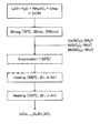
- FIG. 3 is a flowchart showing an example of a method for producing a positive electrode active material according to the second embodiment.
- lithium hydroxide monohydrate is prepared as a Li source, ammonium vanadate as a V source, and urea as a chelating agent.
- Ethanol is added to these raw materials and a stirring bar, and the mixture is stirred under predetermined conditions.
- cobalt nitrate hexahydrate, nickel nitrate hexahydrate and manganese nitrate hexahydrate are added as Co source, Ni source and Mn source, respectively, to obtain a raw material solution.
- ethanol contained in the raw material solution is removed, and the obtained composition is subjected to heat treatment. Thereby, a positive electrode active material is obtained.
- a part of Co constituting the inverse spinel structure is substituted with Ni and Mn, whereby a positive electrode active material that exhibits a very good discharge capacity can be obtained.
- a positive electrode active material exhibiting a very good discharge capacity can be obtained by using a transition metal constituting an inverse spinel structure as a ternary of Co, Ni, and Mn.
- a highly dispersible composition can be obtained by preparing a raw material solution once and removing the solvent after that instead of a so-called simple solid phase method. By performing a heat treatment on the composition, there is an advantage that an inverse spinel structure is easily formed.
- the manufacturing method of the positive electrode active material of a 2nd embodiment is demonstrated for every process.
- the preparation step in the second embodiment is a step of preparing a raw material solution in which a Li source, a Co source, a Ni source, a Mn source, and a V source are dissolved or dispersed in a solvent.
- the raw material solution is a solution in which a Li source, a Co source, a Ni source, a Mn source, and a V source are dissolved or dispersed in a solvent.
- the Li source, Co source, Ni source, and V source are the same as those described in the first embodiment.
- the Mn source include inorganic salts, complexes, oxides, hydroxides, and the like.
- the inorganic salt include carbonates, nitrates, hydrochlorides, oxalates, and ammonium salts.
- the Mn source specifically, include Mn (NO 3) 2, MnCO 3, Mn (CH 3 COO) 2 ⁇ 4H 2 O, MnSO 4 ⁇ H 2 O, MnC 2 O 4 ⁇ 2H 2 O , etc. be able to. Further, other matters are basically the same as the contents described in the first embodiment.
- the present invention is not limited to the above embodiment.
- the above-described embodiment is an exemplification, and the present invention has substantially the same configuration as the technical idea described in the claims of the present invention, and any device that exhibits the same function and effect is the present invention. It is included in the technical scope of the invention.
- a SUS 2032 type coin cell was produced.
- the positive electrode active materials obtained in Examples 1, 2, 4, and 5 have a crystal phase of LiM 1-x Mn x VO 4 as a single phase.
- a peak that seemed to be slightly derived from impurities was confirmed.
- Example 2 Next, calcination was performed for 2 hours under the conditions of an air atmosphere and 300 ° C., and then a main calcination was performed for 2 hours under the conditions of air atmosphere and 700 ° C., thereby obtaining a positive electrode active material. Further, an evaluation battery was obtained in the same manner as in Example 1 except that the obtained positive electrode active material was used.
Landscapes
- Chemical & Material Sciences (AREA)
- Electrochemistry (AREA)
- General Chemical & Material Sciences (AREA)
- Chemical Kinetics & Catalysis (AREA)
- Engineering & Computer Science (AREA)
- Inorganic Chemistry (AREA)
- Organic Chemistry (AREA)
- Materials Engineering (AREA)
- Manufacturing & Machinery (AREA)
- Crystallography & Structural Chemistry (AREA)
- Physics & Mathematics (AREA)
- Condensed Matter Physics & Semiconductors (AREA)
- General Physics & Mathematics (AREA)
- Battery Electrode And Active Subsutance (AREA)
- Secondary Cells (AREA)
Abstract
本発明は、良好な放電容量を発揮する正極活物質を提供することを課題とする。 本発明においては、LiM1-xFexVO4(MはCoまたはNiであり、xは0<x<1を満たす)で表される逆スピネル型構造の結晶相を有することを特徴とする正極活物質を提供することにより、上記課題を解決する。
Description
本発明は、良好な放電容量を発揮する正極活物質に関する。
近年におけるパソコン、ビデオカメラおよび携帯電話等の情報関連機器や通信機器等の急速な普及に伴い、その電源として利用される電池の開発が重要視されている。また、自動車産業界等においても、電気自動車用あるいはハイブリッド自動車用の高出力かつ高容量の電池の開発が進められている。現在、種々の電池の中でも、エネルギー密度が高いという観点から、リチウム電池が注目を浴びている。
リチウム電池は、通常、正極層と、負極層と、正極層および負極層の間に形成された電解質層とを備える。また、正極層および負極層は、通常、それぞれ正極活物質および負極活物質を有する。活物質は電池の性能を決定する重要な部材であり、種々の研究が行われている。例えば、特許文献1においては、正極の一部が逆スピネル型構造を有するリチウム遷移金属酸化物で構成されているリチウム電池が開示されている。さらに、リチウム遷移金属酸化物として、LiNiVO4、LiCoVO4、LiCuVO4が開示されている。
逆スピネル型構造の活物質は高い電位を有するため、正極活物質として有用である。しかしながら、逆スピネル型構造の活物質を正極活物質として用いた場合、十分な放電容量が得られないという問題がある。
本発明は、上記実情に鑑みてなされたものであり、良好な放電容量を発揮する正極活物質を提供することを主目的とする。
上記課題を解決するために、本発明においては、LiM1-xFexVO4(MはCoまたはNiであり、xは0<x<1を満たす)で表される逆スピネル型構造の結晶相を有することを特徴とする正極活物質を提供する。
本発明によれば、逆スピネル型構造を構成するCoまたはNiの一部をFeで置換することにより、良好な放電容量を発揮する正極活物質とすることができる。
上記発明においては、上記xが、0<x≦0.3を満たすことが好ましい。
また、本発明においては、LiCo1-x-yNixMnyVO4(xおよびyは、0<x、0<y、x+y<1を満たす)で表される逆スピネル型構造の結晶相を有することを特徴とする正極活物質を提供する。
本発明によれば、逆スピネル型構造を構成するCoの一部を、NiおよびMnで置換することにより、極めて良好な放電容量を発揮する正極活物質とすることができる。別の表現を用いると、逆スピネル型構造を構成する遷移金属を、Co、Ni、Mnの三元とすることにより、極めて良好な放電容量を発揮する正極活物質とすることができる。
上記発明においては、上記xおよび上記yが、ともに1/3であることが好ましい。
上記発明においては、正極活物質が、LiaCo1-x-yNixMnyVO4(aは1≦a≦1.3を満たす)の組成を有することが好ましい。
また、本発明においては、正極活物質を含有する正極層と、負極活物質を含有する負極層と、上記正極層および上記負極層の間に形成された電解質層とを有するリチウム電池であって、上記正極活物質が、上述した正極活物質であることを特徴とするリチウム電池を提供する。
本発明によれば、上述した正極活物質を用いることで、良好な放電容量を有するリチウム電池とすることができる。
また、本発明においては、Li源、M源(MはCoまたはNiである)、Fe源およびV源が、溶媒に溶解または分散した原料溶液を調製する調製工程と、上記原料溶液に含まれる上記溶媒を除去し、さらに熱処理を行うことにより、LiM1-xFexVO4(xは0<x<1を満たす)で表される逆スピネル型構造の結晶相を有する正極活物質を得る熱処理工程と、を有することを特徴とする正極活物質の製造方法を提供する。
本発明によれば、逆スピネル型構造を構成するCoまたはNiの一部をFeで置換することにより、良好な放電容量を発揮する正極活物質を得ることができる。
また、本発明においては、Li源、Co源、Ni源、Mn源およびV源が、溶媒に溶解または分散した原料溶液を調製する調製工程と、上記原料溶液に含まれる上記溶媒を除去し、さらに熱処理を行うことにより、LiCo1-x-yNixMnyVO4(xおよびyは、0<x、0<y、x+y<1を満たす)で表される逆スピネル型構造の結晶相を有する正極活物質を得る熱処理工程と、を有することを特徴とする正極活物質の製造方法を提供する。
本発明によれば、逆スピネル型構造を構成するCoの一部を、NiおよびMnで置換することにより、極めて良好な放電容量を発揮する正極活物質を得ることができる。別の表現を用いると、逆スピネル型構造を構成する遷移金属を、Co、Ni、Mnの三元とすることにより、極めて良好な放電容量を発揮する正極活物質を得ることができる。
本発明の正極活物質は、良好な放電容量を発揮できるという効果を奏する。
以下、本発明の正極活物質、リチウム電池、および正極活物質の製造方法について、詳細に説明する。
A.正極活物質
本発明の正極活物質は、2つの実施態様に大別することができる。本発明の正極活物質の製造方法について、第一実施態様および第二実施態様に分けて説明する。
本発明の正極活物質は、2つの実施態様に大別することができる。本発明の正極活物質の製造方法について、第一実施態様および第二実施態様に分けて説明する。
1.第一実施態様
第一実施態様の正極活物質は、LiM1-xFexVO4(MはCoまたはNiであり、xは0<x<1を満たす)で表される逆スピネル型構造の結晶相を有することを特徴とするものである。
第一実施態様の正極活物質は、LiM1-xFexVO4(MはCoまたはNiであり、xは0<x<1を満たす)で表される逆スピネル型構造の結晶相を有することを特徴とするものである。
第一実施態様によれば、逆スピネル型構造を構成するCoまたはNiの一部をFeで置換することにより、良好な放電容量を発揮する正極活物質とすることができる。従来、逆スピネル型構造の活物質は、電位が高いが、十分な放電容量を発揮することができなかった。その理由について、正スピネル型構造の活物質と比較することで説明する。正スピネル型構造の活物質として、例えばLiMn2O4が知られている。結晶の空間群の観点に基づくと、LiMn2O4には、8aにLi原子があり、16dにMn原子があり、32eにO原子がある空間群Fd3-mがある。LiMn2O4には、中央部にMnを有し、頂点にO原子を有する八面体構造のトンネルが形成され、そのトンネル内をLiイオンが移動すると考えられる。
これに対して、逆スピネル型構造の活物質として、例えばLiCoVO4が知られている。結晶の空間群の観点に基づくと、LiCoVO4には、8aにV原子があり、16dにLi原子およびCo原子があり、32eにO原子がある空間群Fd3-mがあると推測される。LiCoVO4には、Liイオンの移動に適したトンネルが形成されていないと推測される。このように、逆スピネル型構造におけるLi原子は、正スピネル型構造とは異なるサイトに存在し、さらに、逆スピネル型構造では、Liイオンの移動に適したトンネルが形成されていないことから、十分な放電容量を発揮することができなかったと考えられる。第一実施態様の正極活物質が良好な放電容量を発揮できる理由としては、CoまたはNiの一部をFeで置換することにより、おそらく、トンネルの形状が、Liイオンの移動(拡散)に適した形状に変化したためであると考えられる。なお、例えば特許文献1に記載されているLiNiVO4、LiCoVO4、LiCuVO4のように、遷移金属(V、Co、Cu等)が一種類だけだと、Liイオンが移動するトンネルの形状を、変化させることはできない。また、第一実施態様においては、Fe元素に特有の効果により、放電容量が向上した可能性もある。
第一実施態様の正極活物質は、LiM1-xFexVO4(MはCoまたはNiであり、xは0<x<1を満たす)で表される逆スピネル型構造の結晶相を有する。この逆スピネル型構造の結晶相の存在は、例えばX線回折(XRD)測定により確認できる。例えば、LiCo1-xFexVO4(0<x<1)結晶相は、通常、2θ=18.5°、30.5°、36.5°、37.7°、43.8°、54.3°、57.9°、63.7°付近に典型的なピークを有する。なお、このピークの位置は、±1°の範囲内で前後していても良い。例えば、LiNi1-xFexVO4(0<x<1)結晶相は、通常、2θ=18.7°、30.7°、36.2°、37.9°、44.0°、54.7°、58.3°、64.1°付近に典型的なピークを有する。なお、このピークの位置は、±1°の範囲内で前後していても良い。
また、上記xの値は、x=0の場合よりも高い放電容量が得られる値であることが好ましい。上記xの値は、例えば0.3以下であることが好ましく、0.25以下であることがより好ましい。xの値が大きすぎると、他の結晶相の割合が高くなる可能性があるからである。一方、上記xの値は、通常、0より大きく、0.05以上であることが好ましく、0.1以上であることがより好ましい。xの値が小さすぎると、放電容量の向上が図れない可能性があるからである。
また、第一実施態様の正極活物質は、上記逆スピネル型構造の結晶相を少なくとも有すれば良いが、主相として有することが好ましい。「主相として有する」とは、正極活物質に含まれる全結晶相に対して、上記逆スピネル型構造の結晶相の割合が最も多いことをいう。さらに、上記逆スピネル型構造の結晶相の割合は、例えば50mol%以上であることが好ましく、70mol%以上であることがより好ましく、90mol%以上であることがさらに好ましい。放電容量の向上をより図ることができるからである。特に、第一実施態様の正極活物質は、上記逆スピネル型構造の結晶相を単相として有することが好ましい。なお、上記逆スピネル型構造の結晶相の割合は、リートベルト解析により確認することができる。
また、第一実施態様の正極活物質は、LiaM1-xFexVO4の組成を有することが好ましい。xについては、上述した内容と同様である。aの値は、例えば0.8以上であることが好ましく、0.9以上であることがより好ましい。aの値が小さすぎると、充分な放電容量が得られない可能性があるからである。一方、aの値は、例えば1.2以下であることが好ましく、1.1以下であることがより好ましい。aの値が大きすぎると、充分な放電容量が得られない可能性があるからである。また、正極活物質の作動電位は、リチウム基準で、例えば4V以上であることが好ましい。
第一実施態様の正極活物質の形状は、特に限定されるものではなく、粒子状、薄膜状等を挙げることができる。正極活物質の形状が、粒子状である場合、その平均粒径(D50)は、特に限定されるものではないが、例えば1nm~100μmの範囲内であり、10nm~30μmの範囲内であることが好ましい。
また、第一実施態様の正極活物質の製造方法は、特に限定されるものではないが、例えば、後述する「C.正極活物質の製造方法 1.第一実施態様」に記載する方法を挙げることができる。
2.第二実施態様
第二実施態様の正極活物質は、LiCo1-x-yNixMnyVO4(xおよびyは、0<x、0<y、x+y<1を満たす)で表される逆スピネル型構造の結晶相を有することを特徴とするものである。
第二実施態様の正極活物質は、LiCo1-x-yNixMnyVO4(xおよびyは、0<x、0<y、x+y<1を満たす)で表される逆スピネル型構造の結晶相を有することを特徴とするものである。
第二実施態様によれば、逆スピネル型構造を構成するCoの一部を、NiおよびMnで置換することにより、極めて良好な放電容量を発揮する正極活物質とすることができる。別の表現を用いると、逆スピネル型構造を構成する遷移金属を、Co、Ni、Mnの三元とすることにより、極めて良好な放電容量を発揮する正極活物質とすることができる。上述した第一実施態様に記載したように、逆スピネル型構造を有する活物質であるLiCoVO4において、Li原子とCo原子とは同じサイトに存在する。そのため、Liが挿入脱離しにくく、従来は、初期容量が理論容量の半分以下しか得られなかった。一方、第二実施態様においては、後述する実施例に記載するように、逆スピネル型構造における遷移金属のサイトに、イオン半径の異なる特定の金属(Co、Ni、Mn)を配置することにより、イオン拡散パスが変化し、Liが挿入脱離しやすくなり、放電容量が飛躍的に向上したと考えられる。なお、第二実施態様においても、上述した第一実施態様と同様に、逆スピネル型構造の結晶相中に、Liイオンの移動に適したトンネルが形成されていると推測される。
第二実施態様の正極活物質は、LiCo1-x-yNixMnyVO4(xおよびyは、0<x、0<y、x+y<1を満たす)で表される逆スピネル型構造の結晶相を有する。この逆スピネル型構造の結晶相の存在は、例えばX線回折(XRD)測定により確認できる。この結晶相は、通常、2θ=18.5°、30.5°、36.0°、37.7°、43.8°、54.3°、57.9°、63.7°付近に典型的なピークを有する。なお、このピークの位置は、±1°の範囲内で前後していても良い。
また、LiCo1-x-yNixMnyVO4におけるxおよびyの値は、x=0およびy=0の場合よりも高い放電容量が得られる値であることが好ましい。上記xは、Niの割合を規定するものであり、Niは、正極活物質の高電位化に寄与すると考えられる。上記xの値は、例えば0.05以上であり、0.1以上であることが好ましい。一方、上記xの値は、例えば0.9以下であり、0.8以下であることが好ましく、0.5以下であることがさらに好ましく、0.4以下であることが特に好ましい。上記yは、Mnの割合を規定するものであり、Mnは、正極活物質の高電位化に寄与すると考えられる。上記yの値は、例えば0.05以上であり、0.1以上であることが好ましい。一方、上記yの値は、例えば0.9以下であり、0.8以下であることが好ましく、0.5以下であることがさらに好ましく、0.4以下であることが特に好ましい。なお、逆スピネル型構造の形成という観点からは、yは0.5以下が好ましい。上記(1-x-y)は、Coの割合を規定するものである。上記(1-x-y)の値は、例えば0.1以上であり、0.2以上であることが好ましい。一方、上記(1-x-y)の値は、例えば0.9以下であり、0.8以下であることが好ましく、0.5以下であることがさらに好ましく、0.4以下であることが特に好ましい。特に、第二実施態様においては、上記結晶相が、LiCo1/3Ni1/3Mn1/3VO4結晶相であることが好ましい。
また、第二実施態様の正極活物質は、上記逆スピネル型構造の結晶相を少なくとも有すれば良いが、主相として有することが好ましい。「主相として有する」とは、正極活物質に含まれる全結晶相に対して、上記逆スピネル型構造の結晶相の割合が最も多いことをいう。さらに、上記逆スピネル型構造の結晶相の割合は、例えば50mol%以上であることが好ましく、70mol%以上であることがより好ましく、90mol%以上であることがさらに好ましい。放電容量の向上をより図ることができるからである。特に、第二実施態様の正極活物質は、上記逆スピネル型構造の結晶相を単相として有することが好ましい。なお、上記逆スピネル型構造の結晶相の割合は、リートベルト解析により確認することができる。
また、第二実施態様の正極活物質は、LiaCo1-x-yNixMnyVO4の組成を有することが好ましい。xおよびyについては、上述した内容と同様である。aの値は、例えば0.8以上であることが好ましく、0.9以上がより好ましく、1以上であることがさらに好ましい。aの値が小さすぎると、充分な放電容量が得られない可能性があるからである。一方、aの値は、例えば1.5以下であることが好ましく、1.3以下であることがより好ましい。aの値が大きすぎると、充分な放電容量が得られない可能性があるからである。また、正極活物質の作動電位は、リチウム基準で、例えば4V以上であることが好ましい。
第二実施態様の正極活物質の形状は、特に限定されるものではなく、粒子状、薄膜状等を挙げることができる。正極活物質の形状が、粒子状である場合、その平均粒径(D50)は、特に限定されるものではないが、例えば1nm~100μmの範囲内であり、10nm~30μmの範囲内であることが好ましい。
また、第二実施態様の正極活物質の製造方法は、特に限定されるものではないが、例えば、後述する「C.正極活物質の製造方法 2.第二実施態様」に記載する方法を挙げることができる。
B.リチウム電池
次に、本発明のリチウム電池について説明する。本発明のリチウム電池は、正極活物質を含有する正極層と、負極活物質を含有する負極層と、上記正極層および上記負極層の間に形成された電解質層とを有するリチウム電池であって、上記正極活物質が、上述した正極活物質であることを特徴とするものである。
次に、本発明のリチウム電池について説明する。本発明のリチウム電池は、正極活物質を含有する正極層と、負極活物質を含有する負極層と、上記正極層および上記負極層の間に形成された電解質層とを有するリチウム電池であって、上記正極活物質が、上述した正極活物質であることを特徴とするものである。
図1は、本発明のリチウム電池の一例を示す概略断面図である。図1に示されるリチウム電池10は、正極層1と、負極層2と、正極層1および負極層2の間に形成された電解質層3と、正極層1の集電を行う正極集電体4と、負極層2の集電を行う負極集電体5と、これらの部材を収納する電池ケース6とを有するものである。なお、例えば電解質層3が液体電解質から構成される場合、電解質層3はセパレータを備えていても良い。一方、電解質層3が固体電解質から構成される場合、通常、電解質層3はセパレータを備える必要はない。また、本発明のリチウム電池は、正極層2に含まれる正極活物質が、上述した正極活物質であることを大きな特徴とする。
本発明によれば、上述した正極活物質を用いることで、良好な放電容量を有するリチウム電池とすることができる。
以下、本発明のリチウム電池について、構成ごとに説明する。
以下、本発明のリチウム電池について、構成ごとに説明する。
1.正極層
本発明における正極層は、少なくとも正極活物質を含有する層である。また、正極層は、正極活物質の他に、導電化材、結着材および固体電解質材料の少なくとも一つを含有していても良い。本発明における正極活物質については、上記「A.正極活物質」に記載した内容と同様である。
本発明における正極層は、少なくとも正極活物質を含有する層である。また、正極層は、正極活物質の他に、導電化材、結着材および固体電解質材料の少なくとも一つを含有していても良い。本発明における正極活物質については、上記「A.正極活物質」に記載した内容と同様である。
導電化材の材料としては、例えば炭素材料を挙げることができる。さらに、炭素材料としては、具体的には、アセチレンブラック、ケッチェンブラック、カーボンブラック、コークス、炭素繊維、黒鉛等を挙げることができる。また、結着材の材料としては、例えばポリフッ化ビニリデン(PVDF)、ポリテトラフルオロエチレン(PTFE)等のフッ素系結着材、および、スチレンブタジエンゴム等のゴム系結着材等を挙げることができる。また、固体電解質材料については、「3.電解質層」に記載する固体電解質材料等を挙げることができる。
正極層における正極活物質の含有量は、容量の観点からはより多いことが好ましく、例えば60重量%~99重量%の範囲内、中でも70重量%~95重量%の範囲内であることが好ましい。また、導電化材の含有量は、所望の電子伝導性を確保できれば、より少ないことが好ましく、例えば1重量%~30重量%の範囲内であることが好ましい。正極層の厚さは、リチウム電池の構成によって大きく異なるものであるが、例えば0.1μm~1000μmの範囲内であることが好ましい。
2.負極層
本発明における負極層は、少なくとも負極活物質を含有する層である。また、負極層は、負極活物質の他に、導電化材、結着材および固体電解質材料の少なくとも一つを含有していても良い。負極活物質としては、In、Al、SiおよびSn等の金属活物質、およびメソカーボンマイクロビーズ(MCMB)、高配向性グラファイト(HOPG)、ハードカーボン、ソフトカーボン等のカーボン活物質等を挙げることができる。また、負極層に用いられる、導電化材、結着材および固体電解質材料の種類および割合については、上述した正極層に記載した内容と同様である。
本発明における負極層は、少なくとも負極活物質を含有する層である。また、負極層は、負極活物質の他に、導電化材、結着材および固体電解質材料の少なくとも一つを含有していても良い。負極活物質としては、In、Al、SiおよびSn等の金属活物質、およびメソカーボンマイクロビーズ(MCMB)、高配向性グラファイト(HOPG)、ハードカーボン、ソフトカーボン等のカーボン活物質等を挙げることができる。また、負極層に用いられる、導電化材、結着材および固体電解質材料の種類および割合については、上述した正極層に記載した内容と同様である。
負極層における負極活物質の含有量は、容量の観点からはより多いことが好ましく、例えば60重量%~99重量%の範囲内、中でも70重量%~95重量%の範囲内であることが好ましい。また、負極層の厚さは、リチウム電池の構成によって大きく異なるものであるが、例えば0.1μm~1000μmの範囲内であることが好ましい。
3.電解質層
本発明における電解質層は、上記正極層および上記負極層の間に形成される層である。電解質層を介して、正極活物質と負極活物質との間のイオン伝導を行う。電解質層の形態は、特に限定されるものではなく、液体電解質層、ゲル電解質層、固体電解質層等を挙げることができる。
本発明における電解質層は、上記正極層および上記負極層の間に形成される層である。電解質層を介して、正極活物質と負極活物質との間のイオン伝導を行う。電解質層の形態は、特に限定されるものではなく、液体電解質層、ゲル電解質層、固体電解質層等を挙げることができる。
液体電解質層は、非水電解液を用いてなる層であることが好ましい。非水電解液は、通常、リチウム塩および非水溶媒を含有する。リチウム塩としては、例えばLiPF6、LiBF4、LiClO4、LiAsF6等の無機リチウム塩、およびLiCF3SO3、LiN(CF3SO2)2、LiN(C2F5SO2)2、LiC(CF3SO2)3等の有機リチウム塩等を挙げることができる。非水溶媒としては、例えばエチレンカーボネート(EC)、プロピレンカーボネート(PC)、ジメチルカーボネート(DMC)、ジエチルカーボネート(DEC)、エチルメチルカーボネート(EMC)、ブチレンカーボネート(BC)、γ-ブチロラクトン、スルホラン、アセトニトリル、1,2-ジメトキシメタン、1,3-ジメトキシプロパン、ジエチルエーテル、テトラヒドロフラン、2-メチルテトラヒドロフランおよびこれらの混合物等を挙げることができる。非水電解液におけるリチウム塩の濃度は、例えば0.5mol/L~3mol/Lの範囲内である。
ゲル電解質層は、例えば、非水電解液にポリマーを添加してゲル化することで得ることができる。具体的には、非水電解液に、ポリエチレンオキシド(PEO)、ポリアクリルニトリル(PAN)またはポリメチルメタクリレート(PMMA)等のポリマーを添加することにより、ゲル化を行うことができる。
固体電解質層は、固体電解質材料を用いてなる層である。固体電解質材料としては、例えば、酸化物固体電解質材料および硫化物固体電解質材料を挙げることができる。Liイオン伝導性を有する酸化物固体電解質材料としては、例えば、Li1+xAlxGe2-x(PO4)3(0≦x≦2)、Li1+xAlxTi2-x(PO4)3(0≦x≦2)、LiLaTiO(例えば、Li0.34La0.51TiO3)、LiPON(例えば、Li2.9PO3.3N0.46)、LiLaZrO(例えば、Li7La3Zr2O12)等を挙げることができる。一方、Liイオン伝導性を有する硫化物固体電解質材料としては、例えば、Li2S-P2S5化合物、Li2S-SiS2化合物、Li2S-GeS2化合物等を挙げることができる。
電解質層の厚さは、電解質の種類およびリチウム電池の構成によって大きく異なるものであるが、例えば0.1μm~1000μmの範囲内、中でも0.1μm~300μmの範囲内であることが好ましい。
4.その他の構成
本発明のリチウム電池は、上述した正極層、負極層および電解質層を少なくとも有するものである。さらに通常は、正極層の集電を行う正極集電体、および負極層の集電を行う負極集電体を有する。集電体の材料としては、例えばSUS、アルミニウム、銅、ニッケル、鉄、チタンおよびカーボン等を挙げることができる。本発明のリチウム電池は、正極層および負極層の間に、セパレータを有していても良い。より安全性の高い電池を得ることができるからである。
本発明のリチウム電池は、上述した正極層、負極層および電解質層を少なくとも有するものである。さらに通常は、正極層の集電を行う正極集電体、および負極層の集電を行う負極集電体を有する。集電体の材料としては、例えばSUS、アルミニウム、銅、ニッケル、鉄、チタンおよびカーボン等を挙げることができる。本発明のリチウム電池は、正極層および負極層の間に、セパレータを有していても良い。より安全性の高い電池を得ることができるからである。
5.リチウム電池
本発明のリチウム電池は、一次電池であっても良く、二次電池であっても良いが、中でも、二次電池であることが好ましい。繰り返し充放電でき、例えば車載用電池として有用だからである。また、本発明のリチウム電池の形状としては、例えば、コイン型、ラミネート型、円筒型および角型等を挙げることができる。また、リチウム電池の製造方法は、特に限定されるものではなく、一般的なリチウム電池における製造方法と同様である。
本発明のリチウム電池は、一次電池であっても良く、二次電池であっても良いが、中でも、二次電池であることが好ましい。繰り返し充放電でき、例えば車載用電池として有用だからである。また、本発明のリチウム電池の形状としては、例えば、コイン型、ラミネート型、円筒型および角型等を挙げることができる。また、リチウム電池の製造方法は、特に限定されるものではなく、一般的なリチウム電池における製造方法と同様である。
C.正極活物質の製造方法
次に、本発明の正極活物質の製造方法について説明する。本発明の正極活物質の製造方法は、2つの実施態様に大別することができる。本発明の正極活物質の製造方法について、第一実施態様および第二実施態様に分けて説明する。
次に、本発明の正極活物質の製造方法について説明する。本発明の正極活物質の製造方法は、2つの実施態様に大別することができる。本発明の正極活物質の製造方法について、第一実施態様および第二実施態様に分けて説明する。
1.第一実施態様
第一実施態様の正極活物質の製造方法は、Li源、M源(MはCoまたはNiである)、Fe源およびV源が、溶媒に溶解または分散した原料溶液を調製する調製工程と、上記原料溶液に含まれる上記溶媒を除去し、さらに熱処理を行うことにより、LiM1-xFexVO4(xは0<x<1を満たす)で表される逆スピネル型構造の結晶相を有する正極活物質を得る熱処理工程と、を有することを特徴とするものである。
第一実施態様の正極活物質の製造方法は、Li源、M源(MはCoまたはNiである)、Fe源およびV源が、溶媒に溶解または分散した原料溶液を調製する調製工程と、上記原料溶液に含まれる上記溶媒を除去し、さらに熱処理を行うことにより、LiM1-xFexVO4(xは0<x<1を満たす)で表される逆スピネル型構造の結晶相を有する正極活物質を得る熱処理工程と、を有することを特徴とするものである。
図2は、第一実施態様の正極活物質の製造方法の一例を示すフローチャートである。図2においては、Li源として水酸化リチウム一水和物、V源としてバナジン酸アンモニウム、キレート剤として尿素を準備する。これらの原料および撹拌子に水を加え、所定の条件で撹拌する。その後、Co源(またはNi源)およびFe源として、それぞれ硝酸コバルト六水和物(硝酸ニッケル六水和物)および硝酸鉄九水和物を添加し、原料溶液を得る。次に、原料溶液に含まれる水を除去し、得られた組成物に熱処理を行う。これにより、正極活物質が得られる。
第一実施態様によれば、逆スピネル型構造を構成するCoまたはNiの一部をFeで置換することにより、良好な放電容量を発揮する正極活物質を得ることができる。また、第一実施態様によれば、いわゆる単純な固相法ではなく、一度原料溶液を作製し、その後溶媒を除去することで、分散性の高い組成物が得られる。その組成物に対して熱処理を行うことで、逆スピネル型構造が形成されやすくなるという利点がある。
以下、第一実施態様の正極活物質の製造方法について、工程ごとに説明する。
以下、第一実施態様の正極活物質の製造方法について、工程ごとに説明する。
(1)調製工程
第一実施態様における調製工程は、Li源、M源(MはCoまたはNiである)、Fe源およびV源が、溶媒に溶解または分散した原料溶液を調製する工程である。
第一実施態様における調製工程は、Li源、M源(MはCoまたはNiである)、Fe源およびV源が、溶媒に溶解または分散した原料溶液を調製する工程である。
原料溶液は、Li源、M源(Co源またはNi源)、Fe源およびV源が、溶媒に溶解または分散した溶液である。Li源、M源、Fe源およびV源の種類は、それぞれ特に限定されるものではなく、例えば無機塩、錯体、酸化物、水酸化物等を挙げることができる。上記無機塩としては、例えば炭酸塩、硝酸塩、塩酸塩、シュウ酸塩、アンモニウム塩等を挙げることができる。Li源としては、具体的には、LiOH、Li2CO3、Li2O、CH3COOLi・H2O等を挙げることができる。Co源としては、具体的には、Co(NO3)2、CoCO3、Co(CH3COO)2・4H2O、CoSO4・7H2O、CoC2O4・4H2O等を挙げることができる。Ni源としては、具体的には、Ni(NO3)2・6H2O、NiCO3、Ni(CH3COO)2・4H2O、NiSO4・6H2O、NiC2O4・2H2O等を挙げることができる。Fe源としては、具体的には、Fe(NO3)3・9H2O、FeCO3、Fe(CH3COO)2・4H2O、FeSO4・7H2O、FeC2O4等を挙げることができる。V源としては、具体的には、NH4VO3、V2O3、V2O5等を挙げることができる。なお、O源は、特に限定されるものではなく、各原料に含まれる酸素であっても良く、熱処理時の雰囲気に存在する酸素であっても良い。
また、原料溶液は、溶媒を含有する。溶媒としては、例えば、水;メタノール、エタノール、プロパノール等のアルコール等を挙げることができる。さらに、原料溶液は、得られる正極活物質の粒径を小さく制御するために、キレート剤を含有していても良い。このようなキレート剤としては、例えば尿素およびクエン酸等を挙げることができる。
原料溶液における各原料の割合は、特に限定されるものではなく、所望の正極活物質が得られるように調整することが好ましい。また、原料溶液の調製方法としては、例えば、各原料を溶媒に添加し、撹拌する方法を挙げることができる。この際、溶媒への溶解度を考慮し、溶媒への溶解度が低い原料に対しては、撹拌処理を長時間行うことが好ましい。
(2)熱処理工程
第一実施態様における熱処理工程は、上記原料溶液に含まれる上記溶媒を除去し、さらに熱処理を行うことにより、LiM1-xFexVO4(xは0<x<1を満たす)で表される逆スピネル型構造の結晶相を有する正極活物質を得る工程である。
第一実施態様における熱処理工程は、上記原料溶液に含まれる上記溶媒を除去し、さらに熱処理を行うことにより、LiM1-xFexVO4(xは0<x<1を満たす)で表される逆スピネル型構造の結晶相を有する正極活物質を得る工程である。
原料溶液に含まれる溶媒を除去する方法は、特に限定されるものではなく、例えば加熱する方法を挙げることができる。溶媒を除去する際の加熱温度は、例えば60℃~200℃の範囲内であることが好ましく、70℃~130℃の範囲内であることがより好ましい。加熱温度が低すぎると、効率的に溶媒を除去できない可能性があり、加熱温度が高すぎると、不要な副反応が生じる可能性があるからである。また、第一実施態様においては、減圧下で、原料溶液の溶媒を除去しても良い。減圧時の圧力は大気圧よりも低ければ特に限定されるものではなく、効率的に溶媒を除去でき、かつ、突沸の発生を抑制できる程度に、適宜調整することが好ましい。特に、第一実施態様においては、減圧下で、原料溶液を加熱することが好ましい。より効率的に溶媒を除去できるからである。なお、原料溶液の溶媒を除去する処理と、後述する熱処理とは、別工程であっても良く、同じ工程であっても良い。
第一実施態様においては、溶媒を除去した組成物に熱処理を行う。熱処理温度としては、目的とする正極活物質を合成することができれば特に限定されるものではないが、例えば200℃~1000℃の範囲内であることが好ましく、250℃~800℃の範囲内であることがより好ましい。熱処理温度が低すぎると、逆スピネル型構造の結晶相が形成されない可能性があり、熱処理温度が高すぎると、不要な結晶相が生じる可能性があるからである。
熱処理を行う際の雰囲気は、特に限定されるものではないが、酸素を含有する雰囲気であることが好ましい。具体的には、大気雰囲気で熱処理を行うことが好ましい。熱処理時間は、例えば1時間~25時間の範囲内であることが好ましく、2時間~10時間の範囲内であることがより好ましい。加熱方法としては、例えば焼成炉を用いた方法等を挙げることができる。
2.第二実施態様
第二実施態様の正極活物質の製造方法は、Li源、Co源、Ni源、Mn源およびV源が、溶媒に溶解または分散した原料溶液を調製する調製工程と、上記原料溶液に含まれる上記溶媒を除去し、さらに熱処理を行うことにより、LiCo1-x-yNixMnyVO4(xおよびyは、0<x、0<y、x+y<1を満たす)で表される逆スピネル型構造の結晶相を有する正極活物質を得る熱処理工程と、を有することを特徴とするものである。
第二実施態様の正極活物質の製造方法は、Li源、Co源、Ni源、Mn源およびV源が、溶媒に溶解または分散した原料溶液を調製する調製工程と、上記原料溶液に含まれる上記溶媒を除去し、さらに熱処理を行うことにより、LiCo1-x-yNixMnyVO4(xおよびyは、0<x、0<y、x+y<1を満たす)で表される逆スピネル型構造の結晶相を有する正極活物質を得る熱処理工程と、を有することを特徴とするものである。
図3は、第二実施態様の正極活物質の製造方法の一例を示すフローチャートである。図3においては、Li源として水酸化リチウム一水和物、V源としてバナジン酸アンモニウム、キレート剤として尿素を準備する。これらの原料および撹拌子にエタノールを加え、所定の条件で撹拌する。その後、Co源、Ni源およびMn源として、それぞれ硝酸コバルト六水和物、硝酸ニッケル六水和物および硝酸マンガン六水和物を添加し、原料溶液を得る。次に、原料溶液に含まれるエタノールを除去し、得られた組成物に熱処理を行う。これにより、正極活物質が得られる。
第二実施態様によれば、逆スピネル型構造を構成するCoの一部を、NiおよびMnで置換することにより、極めて良好な放電容量を発揮する正極活物質を得ることができる。別の表現を用いると、逆スピネル型構造を構成する遷移金属を、Co、Ni、Mnの三元とすることにより、極めて良好な放電容量を発揮する正極活物質を得ることができる。また、第二実施態様によれば、いわゆる単純な固相法ではなく、一度原料溶液を作製し、その後溶媒を除去することで、分散性の高い組成物が得られる。その組成物に対して熱処理を行うことで、逆スピネル型構造が形成されやすくなるという利点がある。
以下、第二実施態様の正極活物質の製造方法について、工程ごとに説明する。
以下、第二実施態様の正極活物質の製造方法について、工程ごとに説明する。
(1)調製工程
第二実施態様における調製工程は、Li源、Co源、Ni源、Mn源およびV源が、溶媒に溶解または分散した原料溶液を調製する工程である。
第二実施態様における調製工程は、Li源、Co源、Ni源、Mn源およびV源が、溶媒に溶解または分散した原料溶液を調製する工程である。
原料溶液は、Li源、Co源、Ni源、Mn源およびV源が、溶媒に溶解または分散した溶液である。Li源、Co源、Ni源およびV源については、上述した第一実施態様に記載した内容と同様である。また、Mn源としては、例えば無機塩、錯体、酸化物、水酸化物等を挙げることができる。上記無機塩としては、例えば炭酸塩、硝酸塩、塩酸塩、シュウ酸塩、アンモニウム塩等を挙げることができる。Mn源としては、具体的には、Mn(NO3)2、MnCO3、Mn(CH3COO)2・4H2O、MnSO4・H2O、MnC2O4・2H2O等を挙げることができる。また、他の事項についても、基本的には、上述した第一実施態様に記載した内容と同様である。
(2)熱処理工程
第二実施態様における熱処理工程は、上記原料溶液に含まれる上記溶媒を除去し、さらに熱処理を行うことにより、LiCo1-x-yNixMnyVO4(xおよびyは、0<x、0<y、x+y<1を満たす)で表される逆スピネル型構造の結晶相を有する正極活物質を得る工程である。熱処理工程については、基本的に上述した第一実施態様に記載した内容と同様である。
第二実施態様における熱処理工程は、上記原料溶液に含まれる上記溶媒を除去し、さらに熱処理を行うことにより、LiCo1-x-yNixMnyVO4(xおよびyは、0<x、0<y、x+y<1を満たす)で表される逆スピネル型構造の結晶相を有する正極活物質を得る工程である。熱処理工程については、基本的に上述した第一実施態様に記載した内容と同様である。
なお、本発明は、上記実施形態に限定されるものではない。上記実施形態は、例示であり、本発明の特許請求の範囲に記載された技術的思想と実質的に同一な構成を有し、同様な作用効果を奏するものは、いかなるものであっても本発明の技術的範囲に包含される。
以下に実施例を示して、本発明をさらに具体的に説明する。
[実施例1]
(正極活物質の合成)
図2のフローチャートに沿って、正極活物質を合成した。まず、水酸化リチウム一水和物、バナジン酸アンモニウム、尿素および撹拌子に水を加え、70℃、200rpmの条件で30分間撹拌した。次に、硝酸コバルト六水和物および硝酸鉄九水和物を添加した。なお、各原料の割合は、LiCo1-xFexVO4(x=0.1)が得られるように調整した。次に、得られた原料溶液に含まれる水を、エバポレーターにより除去した。この際、原料溶液を120℃に加熱した。次に、大気雰囲気、300℃の条件で2時間仮焼成し、その後、大気雰囲気、700℃の条件で2時間本焼成することにより、正極活物質を得た。
(正極活物質の合成)
図2のフローチャートに沿って、正極活物質を合成した。まず、水酸化リチウム一水和物、バナジン酸アンモニウム、尿素および撹拌子に水を加え、70℃、200rpmの条件で30分間撹拌した。次に、硝酸コバルト六水和物および硝酸鉄九水和物を添加した。なお、各原料の割合は、LiCo1-xFexVO4(x=0.1)が得られるように調整した。次に、得られた原料溶液に含まれる水を、エバポレーターにより除去した。この際、原料溶液を120℃に加熱した。次に、大気雰囲気、300℃の条件で2時間仮焼成し、その後、大気雰囲気、700℃の条件で2時間本焼成することにより、正極活物質を得た。
(評価用電池の作製)
得られた正極活物質と、アセチレンブラック(AB)と、PVDFとを、正極活物質:AB:PVDF=70:25:5の重量比になるように秤量した。この混合物に、分散剤として、N-メチル-2-ピロリドンを添加し、スラリーを作製した。次に、このスラリーをNiメッシュの正極集電体に塗布し、乾燥することで正極層を得た。
得られた正極活物質と、アセチレンブラック(AB)と、PVDFとを、正極活物質:AB:PVDF=70:25:5の重量比になるように秤量した。この混合物に、分散剤として、N-メチル-2-ピロリドンを添加し、スラリーを作製した。次に、このスラリーをNiメッシュの正極集電体に塗布し、乾燥することで正極層を得た。
得られた正極層を用いて、SUS製2032型コインセルを作製した。負極活物質として金属リチウムを用い、非水電解液として、EC:DMC=1:1の体積比で混合した非水溶媒にLiPF6を1mol/Lの割合で溶解させたものを用いた。このようにして、評価用電池を得た。
[実施例2~3、比較例1]
各原料の割合を、それぞれ、x=0.2、x=0.3、x=0に変更したこと以外は、実施例1と同様にして正極活物質を得た。さらに、得られた正極活物質を用いたこと以外は、実施例1と同様にして評価用電池を得た。
各原料の割合を、それぞれ、x=0.2、x=0.3、x=0に変更したこと以外は、実施例1と同様にして正極活物質を得た。さらに、得られた正極活物質を用いたこと以外は、実施例1と同様にして評価用電池を得た。
[実施例4]
硝酸コバルト六水和物の代わりに、硝酸ニッケル六水和物を用いたこと以外は、実施例1と同様にして正極活物質を得た。なお、各原料の割合は、LiNi1-xFexVO4(x=0.1)が得られるように調整した。さらに、得られた正極活物質を用いたこと以外は、実施例1と同様にして評価用電池を得た。
硝酸コバルト六水和物の代わりに、硝酸ニッケル六水和物を用いたこと以外は、実施例1と同様にして正極活物質を得た。なお、各原料の割合は、LiNi1-xFexVO4(x=0.1)が得られるように調整した。さらに、得られた正極活物質を用いたこと以外は、実施例1と同様にして評価用電池を得た。
[実施例5~6、比較例2]
各原料の割合を、それぞれ、x=0.2、x=0.3、x=0に変更したこと以外は、実施例4と同様にして正極活物質を得た。さらに、得られた正極活物質を用いたこと以外は、実施例4と同様にして評価用電池を得た。
各原料の割合を、それぞれ、x=0.2、x=0.3、x=0に変更したこと以外は、実施例4と同様にして正極活物質を得た。さらに、得られた正極活物質を用いたこと以外は、実施例4と同様にして評価用電池を得た。
[評価1]
(XRD測定)
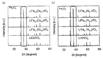
実施例1~6および比較例1、2で得られた正極活物質に対してXRD測定(CuKα線使用)を行った。その結果を図4に示す。図4(a)に示すように、実施例1~3で得られた正極活物質は、2θ=18.5°、30.6°、36.0°、37.7°、43.8°、54.3°、57.9°、63.7°に典型的なピークが得られ、LiCo1-xFexVO4の結晶相を有することが確認された。図4(b)に示すように、実施例4~6で得られた正極活物質は、2θ=18.7°、30.7°、36.2°、37.9°、44.0°、54.7°、58.3°、64.1°に典型的なピークが得られ、LiNi1-xFexVO4の結晶相を有することが確認された。特に、実施例1、2、4、5で得られた正極活物質は、LiM1-xMnxVO4の結晶相を単相として有することが確認された。これに対して実施例3、6で得られた正極活物質は、わずかに不純物由来と思われるピークが確認された。
(XRD測定)
実施例1~6および比較例1、2で得られた正極活物質に対してXRD測定(CuKα線使用)を行った。その結果を図4に示す。図4(a)に示すように、実施例1~3で得られた正極活物質は、2θ=18.5°、30.6°、36.0°、37.7°、43.8°、54.3°、57.9°、63.7°に典型的なピークが得られ、LiCo1-xFexVO4の結晶相を有することが確認された。図4(b)に示すように、実施例4~6で得られた正極活物質は、2θ=18.7°、30.7°、36.2°、37.9°、44.0°、54.7°、58.3°、64.1°に典型的なピークが得られ、LiNi1-xFexVO4の結晶相を有することが確認された。特に、実施例1、2、4、5で得られた正極活物質は、LiM1-xMnxVO4の結晶相を単相として有することが確認された。これに対して実施例3、6で得られた正極活物質は、わずかに不純物由来と思われるピークが確認された。
(充放電試験)
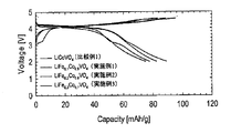
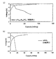
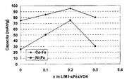
実施例1~3および比較例1で得られた評価用電池に対して充放電試験を行った。充電は0.011mA/cm2で4.8Vまで定電流充電を行った。その後、2Vまで放電を行い、放電容量とした。その結果を図5に示す。また、実施例5および比較例2で得られた評価用電池に対して同様の充放電試験を行った。その結果を図6に示す。さらに、Feの置換量に対する放電容量の変化を図7に示す。図5~図7に示すように、CoまたはNiの一部をFeで置換することにより、放電容量が増加することが確認された。特に、実施例2(Co-Fe系におけるx=0.2)の場合、100mAh/gに近い容量が得られた。Fe単独ではスピネル構造を形成できないが、CoまたはNiの一部をFeで置換することにより、放電容量が増加することが確認された。また、実施例1~3で得られた正極活物質は、いずれも4V以上の高い電位を有し、電位が高いという逆スピネル型構造の特性を保持していることも確認された。
実施例1~3および比較例1で得られた評価用電池に対して充放電試験を行った。充電は0.011mA/cm2で4.8Vまで定電流充電を行った。その後、2Vまで放電を行い、放電容量とした。その結果を図5に示す。また、実施例5および比較例2で得られた評価用電池に対して同様の充放電試験を行った。その結果を図6に示す。さらに、Feの置換量に対する放電容量の変化を図7に示す。図5~図7に示すように、CoまたはNiの一部をFeで置換することにより、放電容量が増加することが確認された。特に、実施例2(Co-Fe系におけるx=0.2)の場合、100mAh/gに近い容量が得られた。Fe単独ではスピネル構造を形成できないが、CoまたはNiの一部をFeで置換することにより、放電容量が増加することが確認された。また、実施例1~3で得られた正極活物質は、いずれも4V以上の高い電位を有し、電位が高いという逆スピネル型構造の特性を保持していることも確認された。
[実施例7]
図3のフローチャートに沿って、正極活物質を合成した。まず、水酸化リチウム一水和物、バナジン酸アンモニウム、尿素および撹拌子にエタノールを加え、70℃、200rpmの条件で30分間撹拌した。次に、硝酸コバルト六水和物、硝酸ニッケル六水和物および硝酸マンガン六水和物を添加した。なお、各原料の割合は、LiaCo1/3Ni1/3Mn1/3VO4(a=1)が得られるように調整した。次に、得られた原料溶液に含まれるエタノールを、エバポレーターにより除去した。この際、原料溶液を120℃に加熱した。次に、大気雰囲気、300℃の条件で2時間仮焼成し、その後、大気雰囲気、700℃の条件で2時間本焼成することにより、正極活物質を得た。さらに、得られた正極活物質を用いたこと以外は、実施例1と同様にして評価用電池を得た。
図3のフローチャートに沿って、正極活物質を合成した。まず、水酸化リチウム一水和物、バナジン酸アンモニウム、尿素および撹拌子にエタノールを加え、70℃、200rpmの条件で30分間撹拌した。次に、硝酸コバルト六水和物、硝酸ニッケル六水和物および硝酸マンガン六水和物を添加した。なお、各原料の割合は、LiaCo1/3Ni1/3Mn1/3VO4(a=1)が得られるように調整した。次に、得られた原料溶液に含まれるエタノールを、エバポレーターにより除去した。この際、原料溶液を120℃に加熱した。次に、大気雰囲気、300℃の条件で2時間仮焼成し、その後、大気雰囲気、700℃の条件で2時間本焼成することにより、正極活物質を得た。さらに、得られた正極活物質を用いたこと以外は、実施例1と同様にして評価用電池を得た。
[実施例8、9]
水酸化リチウム一水和物の割合を、それぞれ、a=1.1、a=1.2に変更し、溶媒をエタノールから水に変更したこと以外は、実施例7と同様にして正極活物質を得た。さらに、得られた正極活物質を用いたこと以外は、実施例7と同様にして評価用電池を得た。
水酸化リチウム一水和物の割合を、それぞれ、a=1.1、a=1.2に変更し、溶媒をエタノールから水に変更したこと以外は、実施例7と同様にして正極活物質を得た。さらに、得られた正極活物質を用いたこと以外は、実施例7と同様にして評価用電池を得た。
[評価2]
(SEM観察)
実施例7~9および比較例1で得られた正極活物質に対してSEM観察を行った。その結果を図8に示す。図8に示すように、いずれも所望の正極活物質が得られたことが確認できた。
(SEM観察)
実施例7~9および比較例1で得られた正極活物質に対してSEM観察を行った。その結果を図8に示す。図8に示すように、いずれも所望の正極活物質が得られたことが確認できた。
(XRD測定)
実施例7~9で得られた正極活物質に対してXRD測定(CuKα線使用)を行った。その結果を図9に示す。図9に示すように、実施例7~9で得られた正極活物質は、2θ=18.6°、30.7°、36.0°、37.7°、43.7°、54.3°、57.9°、63.5°に典型的なピークが得られ、LiCo1-x-yNixMnyVO4の結晶相を有することが確認された。特に、実施例7、8で得られた正極活物質は、LiCo1-x-yNixMnyVO4の結晶相を単相として有することが確認された。これに対して実施例9で得られた正極活物質は、わずかに不純物由来と思われるピークが確認された。
実施例7~9で得られた正極活物質に対してXRD測定(CuKα線使用)を行った。その結果を図9に示す。図9に示すように、実施例7~9で得られた正極活物質は、2θ=18.6°、30.7°、36.0°、37.7°、43.7°、54.3°、57.9°、63.5°に典型的なピークが得られ、LiCo1-x-yNixMnyVO4の結晶相を有することが確認された。特に、実施例7、8で得られた正極活物質は、LiCo1-x-yNixMnyVO4の結晶相を単相として有することが確認された。これに対して実施例9で得られた正極活物質は、わずかに不純物由来と思われるピークが確認された。
(充放電試験)
実施例7~9および比較例1で得られた評価用電池に対して充放電試験を行った。充電は0.011mA/cm2で4.8Vまで定電流充電を行った。その後、2Vまで放電を行い、放電容量とした。その結果を図10に示す。図10に示すように、遷移金属を3元(Co、Ni、Mn)にすることで、放電容量が比較的に向上することが確認された。特に、実施例7(a=1)の場合、放電容量が理論容量近くの140mAh/g程度となった。これは、逆スピネル型構造を有する活物質では革新的な容量である。また、実施例8(a=1.1)および実施例9(a=1.2)においても、放電容量が100mAh/g以上となり、逆スピネル型構造を有する活物質としては、極めて高い容量が得られた。なお、実施例7~9で得られた正極活物質は、いずれも4V以上の高い電位を有し、電位が高いという逆スピネル型構造の特性を保持していることも確認された。
実施例7~9および比較例1で得られた評価用電池に対して充放電試験を行った。充電は0.011mA/cm2で4.8Vまで定電流充電を行った。その後、2Vまで放電を行い、放電容量とした。その結果を図10に示す。図10に示すように、遷移金属を3元(Co、Ni、Mn)にすることで、放電容量が比較的に向上することが確認された。特に、実施例7(a=1)の場合、放電容量が理論容量近くの140mAh/g程度となった。これは、逆スピネル型構造を有する活物質では革新的な容量である。また、実施例8(a=1.1)および実施例9(a=1.2)においても、放電容量が100mAh/g以上となり、逆スピネル型構造を有する活物質としては、極めて高い容量が得られた。なお、実施例7~9で得られた正極活物質は、いずれも4V以上の高い電位を有し、電位が高いという逆スピネル型構造の特性を保持していることも確認された。
1 … 正極層
2 … 負極層
3 … 電解質層
4 … 正極集電体
5 … 負極集電体
6 … 電池ケース
10 … 電池
2 … 負極層
3 … 電解質層
4 … 正極集電体
5 … 負極集電体
6 … 電池ケース
10 … 電池
Claims (8)
- LiM1-xFexVO4(MはCoまたはNiであり、xは0<x<1を満たす)で表される逆スピネル型構造の結晶相を有することを特徴とする正極活物質。
- 前記xが、0<x≦0.3を満たすことを特徴とする請求項1に記載の正極活物質。
- LiCo1-x-yNixMnyVO4(xおよびyは、0<x、0<y、x+y<1を満たす)で表される逆スピネル型構造の結晶相を有することを特徴とする正極活物質。
- 前記xおよび前記yが、ともに1/3であることを特徴とする請求項3に記載の正極活物質。
- LiaCo1-x-yNixMnyVO4(aは1≦a≦1.3を満たす)の組成を有することを特徴とする請求項3または請求項4に記載の正極活物質。
- 正極活物質を含有する正極層と、負極活物質を含有する負極層と、前記正極層および前記負極層の間に形成された電解質層とを有するリチウム電池であって、
前記正極活物質が、請求項1から請求項5までのいずれかの請求項に記載の正極活物質であることを特徴とするリチウム電池。 - Li源、M源(MはCoまたはNiである)、Fe源およびV源が、溶媒に溶解または分散した原料溶液を調製する調製工程と、
前記原料溶液に含まれる前記溶媒を除去し、さらに熱処理を行うことにより、LiM1-xFexVO4(xは0<x<1を満たす)で表される逆スピネル型構造の結晶相を有する正極活物質を得る熱処理工程と、
を有することを特徴とする正極活物質の製造方法。 - Li源、Co源、Ni源、Mn源およびV源が、溶媒に溶解または分散した原料溶液を調製する調製工程と、
前記原料溶液に含まれる前記溶媒を除去し、さらに熱処理を行うことにより、LiCo1-x-yNixMnyVO4(xおよびyは、0<x、0<y、x+y<1を満たす)で表される逆スピネル型構造の結晶相を有する正極活物質を得る熱処理工程と、
を有することを特徴とする正極活物質の製造方法。
Priority Applications (3)
| Application Number | Priority Date | Filing Date | Title |
|---|---|---|---|
| US14/441,357 US20150295243A1 (en) | 2012-11-12 | 2013-11-12 | Cathode active material, lithium battery and method of producing cathode active material |
| CN201380056983.4A CN104823310A (zh) | 2012-11-12 | 2013-11-12 | 正极活性物质、锂电池以及正极活性物质的制造方法 |
| EP13852601.7A EP2919302A4 (en) | 2012-11-12 | 2013-11-12 | ACTIVE MATERIAL FOR POSITIVE ELECTRODES, LITHIUM BATTERY AND MANUFACTURING METHOD FOR A POSITIVE ELECTRODE ACTIVE MATERIAL |
Applications Claiming Priority (2)
| Application Number | Priority Date | Filing Date | Title |
|---|---|---|---|
| JP2012248701A JP2014096330A (ja) | 2012-11-12 | 2012-11-12 | 正極活物質、リチウム電池および正極活物質の製造方法 |
| JP2012-248701 | 2012-11-12 |
Publications (1)
| Publication Number | Publication Date |
|---|---|
| WO2014073701A1 true WO2014073701A1 (ja) | 2014-05-15 |
Family
ID=50684789
Family Applications (1)
| Application Number | Title | Priority Date | Filing Date |
|---|---|---|---|
| PCT/JP2013/080562 WO2014073701A1 (ja) | 2012-11-12 | 2013-11-12 | 正極活物質、リチウム電池および正極活物質の製造方法 |
Country Status (5)
| Country | Link |
|---|---|
| US (1) | US20150295243A1 (ja) |
| EP (1) | EP2919302A4 (ja) |
| JP (1) | JP2014096330A (ja) |
| CN (1) | CN104823310A (ja) |
| WO (1) | WO2014073701A1 (ja) |
Cited By (1)
| Publication number | Priority date | Publication date | Assignee | Title |
|---|---|---|---|---|
| WO2016175313A1 (ja) * | 2015-04-30 | 2016-11-03 | 三井金属鉱業株式会社 | 5v級スピネル型リチウムマンガン含有複合酸化物 |
Families Citing this family (4)
| Publication number | Priority date | Publication date | Assignee | Title |
|---|---|---|---|---|
| JP7074314B2 (ja) * | 2017-11-30 | 2022-05-24 | 国立研究開発法人産業技術総合研究所 | カリウムイオン二次電池用正極活物質及び二次電池 |
| KR102659200B1 (ko) * | 2018-10-24 | 2024-04-19 | 삼성전자주식회사 | 혼합전도체, 이를 포함하는 전기화학 소자 및 그 제조방법 |
| CN109860582B (zh) * | 2018-12-28 | 2022-04-19 | 蜂巢能源科技股份有限公司 | 锂离子电池的正极材料及其制备方法 |
| CN111834615B (zh) * | 2019-04-23 | 2021-11-16 | 四川佰思格新能源有限公司 | 一种复合负极材料及制备方法和锂离子电池 |
Citations (9)
| Publication number | Priority date | Publication date | Assignee | Title |
|---|---|---|---|---|
| JPH06223831A (ja) * | 1993-01-22 | 1994-08-12 | Fuji Photo Film Co Ltd | リチウム二次電池 |
| JPH06318457A (ja) * | 1993-05-07 | 1994-11-15 | Fuji Photo Film Co Ltd | 非水二次電池 |
| JPH07192768A (ja) | 1993-11-09 | 1995-07-28 | Moli Energy 1990 Ltd | リチウム電池およびリチウム電池用正極 |
| JPH0969363A (ja) * | 1995-08-31 | 1997-03-11 | Sony Corp | 正極活物質及び非水電解質二次電池 |
| JPH10188976A (ja) * | 1996-12-25 | 1998-07-21 | Mitsubishi Chem Corp | リチウム二次電池 |
| JPH11354117A (ja) * | 1998-06-04 | 1999-12-24 | Fuji Elelctrochem Co Ltd | 非水電解液2次電池 |
| JP2004047180A (ja) * | 2002-07-09 | 2004-02-12 | Japan Storage Battery Co Ltd | 非水電解質電池 |
| JP2008251497A (ja) * | 2007-03-30 | 2008-10-16 | Toyota Motor Corp | 初充電前リチウムイオン二次電池、リチウムイオン二次電池、車両、および電池搭載機器 |
| JP2009272041A (ja) * | 2008-04-30 | 2009-11-19 | Mitsubishi Materials Corp | リチウムイオン二次電池 |
Family Cites Families (4)
| Publication number | Priority date | Publication date | Assignee | Title |
|---|---|---|---|---|
| PL209387B1 (pl) * | 2000-04-13 | 2011-08-31 | Shell Int Research | Stały element elektrochemiczny oraz jego zastosowanie do dostarczania energii elektrycznej w podwyższonej temperaturze |
| CN101017896A (zh) * | 2007-01-25 | 2007-08-15 | 吉林大学 | 锂离子二次电池正极材料LiNiVO4及其制备方法 |
| JP2013073867A (ja) * | 2011-09-29 | 2013-04-22 | Toppan Printing Co Ltd | 非水電解液二次電池用正極活物質及びその製造方法、並びに非水電解液二次電池 |
| JP2013073906A (ja) * | 2011-09-29 | 2013-04-22 | Toppan Printing Co Ltd | 非水電解液二次電池用正極電極及び非水電解液二次電池 |
-
2012
- 2012-11-12 JP JP2012248701A patent/JP2014096330A/ja active Pending
-
2013
- 2013-11-12 US US14/441,357 patent/US20150295243A1/en not_active Abandoned
- 2013-11-12 CN CN201380056983.4A patent/CN104823310A/zh active Pending
- 2013-11-12 EP EP13852601.7A patent/EP2919302A4/en not_active Withdrawn
- 2013-11-12 WO PCT/JP2013/080562 patent/WO2014073701A1/ja active Application Filing
Patent Citations (9)
| Publication number | Priority date | Publication date | Assignee | Title |
|---|---|---|---|---|
| JPH06223831A (ja) * | 1993-01-22 | 1994-08-12 | Fuji Photo Film Co Ltd | リチウム二次電池 |
| JPH06318457A (ja) * | 1993-05-07 | 1994-11-15 | Fuji Photo Film Co Ltd | 非水二次電池 |
| JPH07192768A (ja) | 1993-11-09 | 1995-07-28 | Moli Energy 1990 Ltd | リチウム電池およびリチウム電池用正極 |
| JPH0969363A (ja) * | 1995-08-31 | 1997-03-11 | Sony Corp | 正極活物質及び非水電解質二次電池 |
| JPH10188976A (ja) * | 1996-12-25 | 1998-07-21 | Mitsubishi Chem Corp | リチウム二次電池 |
| JPH11354117A (ja) * | 1998-06-04 | 1999-12-24 | Fuji Elelctrochem Co Ltd | 非水電解液2次電池 |
| JP2004047180A (ja) * | 2002-07-09 | 2004-02-12 | Japan Storage Battery Co Ltd | 非水電解質電池 |
| JP2008251497A (ja) * | 2007-03-30 | 2008-10-16 | Toyota Motor Corp | 初充電前リチウムイオン二次電池、リチウムイオン二次電池、車両、および電池搭載機器 |
| JP2009272041A (ja) * | 2008-04-30 | 2009-11-19 | Mitsubishi Materials Corp | リチウムイオン二次電池 |
Non-Patent Citations (5)
| Title |
|---|
| AYUKO KITAJO ET AL.: "Gyaku Spinel-gata LiMV04(M=Ni, Co) Seikyoku eno Fe Oyobi, Mn Dope Koka", ABSTRACTS, BATTERY SYMPOSIUM IN JAPAN, vol. 53RD, 13 November 2012 (2012-11-13), pages 99, XP008179103 * |
| AYUKO KITAJO ET AL.: "Gyaku Spinel-kei LiMV04 (M=Ni, Co, Mn) eno Ishu Kinzoku Dope Koka", ABSTRACTS, BATTERY SYMPOSIUM IN JAPAN, vol. 53RD, 13 November 2012 (2012-11-13), pages 100, XP008179109 * |
| GEORGE TING-KUO FEY ET AL.: "Electrochemical performance and 7LiNMR studies on an inverse spinel LiNil/3Col/3Mnl/3V04 for Li-ion batteries", JOURNAL OF POWER SOURCES, vol. 174, no. 2, 6 December 2007 (2007-12-06), pages 1142 - 1146, XP025917716 * |
| GERGE TING-KUO FEY ET AL.: "Synthesis and characterization of a new inverse spinel LiNil/3Col/3Mnl/3V04 for lithium -ion batteries", MATERIALS LETTERS, vol. 60, no. 9-10, May 2006 (2006-05-01), pages 1209 - 1212, XP029168376 * |
| See also references of EP2919302A4 * |
Cited By (3)
| Publication number | Priority date | Publication date | Assignee | Title |
|---|---|---|---|---|
| WO2016175313A1 (ja) * | 2015-04-30 | 2016-11-03 | 三井金属鉱業株式会社 | 5v級スピネル型リチウムマンガン含有複合酸化物 |
| JPWO2016175313A1 (ja) * | 2015-04-30 | 2018-02-22 | 三井金属鉱業株式会社 | 5v級スピネル型リチウムマンガン含有複合酸化物 |
| US10276867B2 (en) | 2015-04-30 | 2019-04-30 | Mitsui Mining & Smelting Co., Ltd. | 5V-class spinel-type lithium-manganese-containing composite oxide |
Also Published As
| Publication number | Publication date |
|---|---|
| EP2919302A1 (en) | 2015-09-16 |
| JP2014096330A (ja) | 2014-05-22 |
| US20150295243A1 (en) | 2015-10-15 |
| EP2919302A4 (en) | 2016-05-18 |
| CN104823310A (zh) | 2015-08-05 |
Similar Documents
| Publication | Publication Date | Title |
|---|---|---|
| US9225005B2 (en) | Positive-electrode material for lithium secondary-battery, process for producing the same, positive electrode for lithium secondary battery, and lithium secondary battery | |
| JP5761617B2 (ja) | 非水電解質二次電池用正極活物質及び非水電解質二次電池 | |
| JP4595475B2 (ja) | 非水系電解質二次電池用正極活物質およびこれを用いた非水系電解質二次電池およびその製造方法 | |
| KR100797099B1 (ko) | 리튬 이차 전지용 양극 활물질, 이의 제조방법 및 이를포함하는 리튬 이차 전지 | |
| JP5987401B2 (ja) | 非水系電解質二次電池用正極活物質とその製造方法および二次電池 | |
| JP6201277B2 (ja) | 非水系電解質二次電池用正極活物質とその製造方法 | |
| JP2010064944A (ja) | リチウムニッケル複合酸化物及びリチウムニッケル複合酸化物を正極活物質に用いた非水系電解質二次電池 | |
| JPWO2012176471A1 (ja) | リチウム含有複合酸化物粉末およびその製造方法 | |
| CN112313817A (zh) | 正极材料和二次电池 | |
| KR20170080104A (ko) | 양극 활물질 및 상기 양극 활물질을 채용한 양극과 리튬 전지 | |
| WO2011118302A1 (ja) | 電池用活物質および電池 | |
| JP5103923B2 (ja) | 非水系電解質二次電池用正極活物質、その製造方法及びそれを用いた非水系電解質二次電池 | |
| JP5145994B2 (ja) | 非水系電解質二次電池用正極活物質とその製造方法 | |
| WO2014073701A1 (ja) | 正極活物質、リチウム電池および正極活物質の製造方法 | |
| CN112424976A (zh) | 正极活性物质和二次电池 | |
| JP2005281128A (ja) | リチウム含有オキシ水酸化鉄の製造方法およびその製造方法で得られたリチウム含有オキシ水酸化鉄を含む電極を用いた非水電解質電気化学セル | |
| JP5109447B2 (ja) | 非水系電解質二次電池用正極活物質、その製造方法及びそれを用いた非水系電解質二次電池 | |
| WO2015045254A1 (ja) | リチウムチタン複合酸化物 | |
| JP5176317B2 (ja) | 非水系電解質二次電池用正極活物質とその製造方法、および、これを用いた非水系電解質二次電池 | |
| KR101278832B1 (ko) | 표면이 피복된 리튬티탄산화물 분말, 이를 구비한 전극, 및 이차전지 | |
| JP2006147500A (ja) | 非水系電解質二次電池用正極活物質とその製造方法、およびこれを用いた非水系電解質二次電池 | |
| JP2013012336A (ja) | 二次電池およびその充電方法 | |
| JP2013060319A (ja) | リチウムマンガン(iv)ニッケル(iii)系酸化物、その酸化物を含むリチウムイオン二次電池用正極活物質、その正極活物質を用いたリチウムイオン二次電池及びそのリチウムイオン二次電池を搭載した車両 | |
| JP5141356B2 (ja) | 非水系電解質二次電池用正極活物質とその製造方法、および、これを用いた非水系電解質二次電池 | |
| JP5181455B2 (ja) | 非水系電解質二次電池用正極活物質とその製造方法、および、これを用いた非水系電解質二次電池 |
Legal Events
| Date | Code | Title | Description |
|---|---|---|---|
| 121 | Ep: the epo has been informed by wipo that ep was designated in this application |
Ref document number: 13852601 Country of ref document: EP Kind code of ref document: A1 |
|
| WWE | Wipo information: entry into national phase |
Ref document number: 14441357 Country of ref document: US |
|
| REEP | Request for entry into the european phase |
Ref document number: 2013852601 Country of ref document: EP |
|
| WWE | Wipo information: entry into national phase |
Ref document number: 2013852601 Country of ref document: EP |
|
| NENP | Non-entry into the national phase |
Ref country code: DE |