WO2014069259A1 - 配管の洗浄方法及び配管の洗浄システム - Google Patents
配管の洗浄方法及び配管の洗浄システム Download PDFInfo
- Publication number
- WO2014069259A1 WO2014069259A1 PCT/JP2013/078346 JP2013078346W WO2014069259A1 WO 2014069259 A1 WO2014069259 A1 WO 2014069259A1 JP 2013078346 W JP2013078346 W JP 2013078346W WO 2014069259 A1 WO2014069259 A1 WO 2014069259A1
- Authority
- WO
- WIPO (PCT)
- Prior art keywords
- water
- cleaning
- pipe
- flow path
- ozone
- Prior art date
- Legal status (The legal status is an assumption and is not a legal conclusion. Google has not performed a legal analysis and makes no representation as to the accuracy of the status listed.)
- Ceased
Links
Images



Classifications
-
- B—PERFORMING OPERATIONS; TRANSPORTING
- B08—CLEANING
- B08B—CLEANING IN GENERAL; PREVENTION OF FOULING IN GENERAL
- B08B9/00—Cleaning hollow articles by methods or apparatus specially adapted thereto
- B08B9/02—Cleaning pipes or tubes or systems of pipes or tubes
- B08B9/027—Cleaning the internal surfaces; Removal of blockages
- B08B9/032—Cleaning the internal surfaces; Removal of blockages by the mechanical action of a moving fluid, e.g. by flushing
-
- B—PERFORMING OPERATIONS; TRANSPORTING
- B08—CLEANING
- B08B—CLEANING IN GENERAL; PREVENTION OF FOULING IN GENERAL
- B08B9/00—Cleaning hollow articles by methods or apparatus specially adapted thereto
- B08B9/02—Cleaning pipes or tubes or systems of pipes or tubes
- B08B9/027—Cleaning the internal surfaces; Removal of blockages
-
- F—MECHANICAL ENGINEERING; LIGHTING; HEATING; WEAPONS; BLASTING
- F28—HEAT EXCHANGE IN GENERAL
- F28G—CLEANING OF INTERNAL OR EXTERNAL SURFACES OF HEAT-EXCHANGE OR HEAT-TRANSFER CONDUITS, e.g. WATER TUBES OR BOILERS
- F28G9/00—Cleaning by flushing or washing, e.g. with chemical solvents
-
- B—PERFORMING OPERATIONS; TRANSPORTING
- B08—CLEANING
- B08B—CLEANING IN GENERAL; PREVENTION OF FOULING IN GENERAL
- B08B2203/00—Details of cleaning machines or methods involving the use or presence of liquid or steam
- B08B2203/005—Details of cleaning machines or methods involving the use or presence of liquid or steam the liquid being ozonated
Definitions
- the present invention relates to a pipe cleaning method and a pipe cleaning system.
- Disassembly cleaning is a method in which each component or part is cleaned after disassembling the equipment.
- in-place cleaning is a system that cleans equipment without disassembling it. It is performed by incorporating a cleaning function into the equipment and is mainly used for piping and containers found in the food manufacturing and food processing industries. In the food production equipment and equipment configured, cleaning is performed by passing a high-pressure cleaning liquid from the outside into the pipe.
- a filling device that fills containers such as bottles and cans with beverages or the like
- a cleaning method for stationary cleaning of liquid passages of filling liquid processing equipment or equipment such as piping equipment connecting these equipment liquid containing nanobubbles was sent to the equipment and allowed to stand still for a predetermined time.
- ozone gas as a nanobubble gas
- a cleaning technique using ozone water it is a cleaning method for electronic materials such as a silicon substrate for a semiconductor and a glass substrate for a liquid crystal, and includes an acidic ozone water cleaning step for cleaning with acid-added ozone water and an alkali.
- an electronic material having an alkaline ozone water cleaning step of cleaning with ozone water see Patent Document 2.
- the conventional technique has a problem in that the concentration of ozone used for cleaning is lowered at the end of the pipe to be cleaned included in the equipment and sufficient cleaning cannot be performed.
- multi-stage stationary cleaning that combines cleaning, sterilization, and deodorizing treatment requires longer cleaning time, uses a large amount of cleaning solution and chemicals, has a heavy load on drainage, and adjusts the temperature of cleaning water.
- sterilization by heating is an indispensable process, but heat exchangers used in the sterilization process easily adhere to dirt, and if the heating temperature is increased, the heat exchanger surface It is known that the content of fixed inorganic substances is increased.
- the subject of this invention is providing the means to wash
- the first invention that solves the above-mentioned problem is A pipe cleaning method for cleaning the inside of a pipe by passing cleaning water through the pipe to be cleaned, Supplying acid to the wash water to prepare wash water having a pH of 4 or less; Mixing ozone gas into the wash water; Passing washing water through the pipe to be washed; It is the washing
- the second invention is A piping cleaning system that cleans the inside of a pipe by passing cleaning water through the pipe to be cleaned.
- Including A cleaning system for piping wherein the cleaning water supplied with acid is circulated in a circulation channel, ozone gas is mixed, and the water is passed through the water supply channel through the piping to be cleaned.
- piping which equipment has can be wash
- a high cleaning ability with high-concentration ozone can be obtained even at the end of a pipe of the equipment and the pipe cleaning efficiency is improved.
- the pipe cleaning method includes: A pipe cleaning method for cleaning the inside of a pipe by passing cleaning water through the pipe to be cleaned, Supplying acid to the wash water to prepare wash water having a pH of 4 or less (acid supply process); A step of mixing ozone gas into the cleaning water (ozone mixing step); A process of passing wash water through the pipe to be cleaned (water flow process); It is a method including.
- the inner surface of the pipe is cleaned through acidic cleaning water in which ozone is dissolved in a hollow pipe provided in equipment or equipment for the purpose of transporting fluid.
- a pipe provided for food production equipment or food production equipment is suitable.
- the pipe cleaning method of the present embodiment is not particularly limited as long as it includes at least each of the steps, but preferably includes the steps.
- Washing water in which high-concentration ozone is dissolved can be prepared by mixing ozone after setting the pH of the washing water to 4 or less.
- the cleaning water refers to a liquid mainly composed of water for cleaning the piping, and the raw water used as a raw material in addition to the acidic cleaning water in which ozone is passed through the piping to be cleaned. And raw water whose pH is adjusted by adding acid.
- raw water water that has been subjected to various treatments such as distilled water, purified water, sterilized water, and water mixed with additives such as surfactants can be used, but tap water is usually used.
- the water temperature of the raw water is not particularly limited, but is preferably near the normal temperature range, for example, around 20 ⁇ 15 ° C.
- an acid is supplied to the wash water to prepare wash water having a pH of 4 or less.
- the supply of the acid is performed, for example, by adding the acid while stirring the cleaning water after storing the cleaning water in an amount necessary for passing water through the pipe in the container.
- a container for storing washing water a container made of a material having acid resistance and resistance to corrosion by ozone is used.
- the acid may be supplied until the pH of the cleaning water is measured with a pH meter and reaches a predetermined value, or a predetermined amount of acid may be added to a predetermined amount of cleaning water.
- the acid to be supplied includes inorganic acids such as nitric acid, nitrous acid, halogen acid, perhalogen acid, halous acid, hypohalous acid, sulfuric acid, sulfurous acid, phosphoric acid, phosphorous acid, carbonic acid, permanganic acid, boric acid, etc.
- any organic acid such as carboxylic acid and sulfonic acid can be used, but an acid that has high solubility in washing water at around room temperature, an acid that does not react with ozone, or an acid that has a high cleaning ability with respect to inorganic substances, Nitric acid is preferably used.
- the pH of the wash water to be prepared is not particularly limited as long as it is pH 4 or less, but is preferably in an acidic region, and more preferably pH 2 or less.
- ozone mixing process In the ozone mixing step, ozone gas is mixed into the cleaning water.
- the mixing of the ozone gas is performed, for example, by allowing the ozone gas to aerate or come into contact with the cleaning water sealed in the sealed container.
- the ozone gas is generated by a method of generating silent discharge or corona discharge in oxygen gas, a method of irradiating the oxygen gas with ultraviolet rays, or the like.
- oxygen gas any of oxygen gas generated by electrolysis, oxygen gas concentrated from the air, and the like are used, but those subjected to purification treatment such as removal of nitrogen are preferable.
- concentration of the ozone gas to be mixed is not particularly limited, but is preferably mixed to a saturated concentration, and is preferably mixed so that the ozone concentration becomes 50 mg / L or more in normal temperature washing water.
- the cleaning water is passed through the pipe to be cleaned.
- the cleaning water is passed through a pump capable of supplying the cleaning water to the downstream end where the pipe structure of the pipe to be cleaned ends. It is preferable that the water flow is performed by connecting the container prepared with the cleaning water mixed with ozone and the pipe to be cleaned by a pipe or the like, and maintaining a sealed state.
- the temperature of the wash water to be passed is preferably in the range of 25 ° C to 60 ° C.
- the flow rate and flow rate of the cleaning water to be passed can be appropriately adjusted according to the capacity, shape, degree of contamination, etc. of the pipe to be cleaned.
- FIG. 1 is a diagram illustrating a relationship between a water supply distance (m) and a dissolved ozone concentration (mg / L) when cleaning water mixed with ozone is supplied to a pipe to be cleaned.
- Supply acid to tap water and prepare wash water with pH 1.2 ( ⁇ ), pH 3.6 ( ⁇ ), pH 6.1 ( ⁇ ), pH 7.2 ( ⁇ ), pH 8.4 ( ⁇ ), respectively.
- ozone gas is mixed until saturation and water is sent to the piping, the results of measuring dissolved ozone in the wash water after water feeding (watering distance 0 m) and after feeding 20 m, 40 m, 60 m, 80 m and 100 m are shown. Yes.
- FIG. 1 shows, the lower the pH of the cleaning water, the higher the initial ozone concentration dissolved in the cleaning water.
- damping of the ozone concentration after water feeding is suppressed, so that the pH of washing water becomes low.
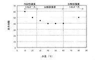
- FIG. 2 is a diagram showing the relationship between the water temperature (° C.) and the cleaning time when the cleaning water is passed through the pipe to be cleaned.
- the temperature of the washing water at room temperature (25 ° C) was adjusted in the range of 10 ° C to 80 ° C, and each was passed through the pipe to be washed, and the time required to wash the pipe to be washed to a predetermined level was measured. Results are shown. As shown in FIG. 2, when the temperature of the cleaning water is in the range of 25 ° C. to 60 ° C., the time required for cleaning is shortened.
- the concentration of ozone dissolved in the cleaning water can be increased by setting the cleaning water to pH 4 or less.
- energy consumption for increasing the concentration of dissolved ozone is reduced.
- high-pressure ozone gas is required. If the cleaning water has a pH of 4 or less, it is possible to easily prepare cleaning water with an ozone concentration of 50 mg / L or more, and about 90% of ozone remains in the cleaning water that has been fed 100 m through the pipe. As a result, the piping cleaning efficiency is improved.
- the washing water's action as an acid improves the washing ability against dirt with a high inorganic content.
- the washing time is shortened and washing is performed. Efficiency is improved.
- Washing water having a water temperature in the range of 25 ° C. to 60 ° C. can be prepared using tap water in a normal temperature range without requiring excessive energy for temperature adjustment.
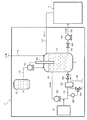
- FIG. 3 is a configuration diagram of the pipe cleaning system 1 according to the embodiment.
- This cleaning system is a device for stationary cleaning of equipment including piping as a component, and after being connected to the pipe to be cleaned P of the equipment to be cleaned, the cleaning water is passed through the pipe to be cleaned.
- This is a cleaning system that cleans the inside of piping.
- acidic ozone water in which ozone is dissolved after making raw water acidic is used as cleaning water.
- the configuration of the piping cleaning system 1 mainly includes a storage tank 10, an acid supply unit 30, an ozone generation unit 20, a circulation pump 420, and a water supply pump 440.
- the storage tank 10 is a sealed container that stores the cleaning water S that is passed through the pipe P to be cleaned.
- the storage tank 10 is used for temporarily storing raw water for preparing the cleaning water S.
- the material of the storage tank 10 is a metal that is resistant to the acid or ozone that comes into contact therewith, for example, stainless steel. Specifically, SUS304, SUS316, etc.
- pH measuring means 530 for measuring the pH of the stored wash water or raw water is provided in the tank of the storage tank 10.
- the storage tank 10 may be provided with other means (not shown), for example, means for measuring the environment in the tank such as temperature measurement means, water level measurement means, pressure measurement means, and stirring means.
- the storage tank 10 includes a water supply path 110 serving as a flow path for raw water, an acid supply path 130 serving as a flow path for acid A, a circulation flow path 120 serving as a flow path for cleaning water S, and a water supply flow path 140. It connects so that it may connect in the tank of the storage tank 10, and forms a series of flow paths in the washing
- the flow path is formed by a closed structure in a pipe or a cleaning system.
- the water supply path 110 connects the water supply and the storage tank 10 and forms a flow path for drawing tap water used as raw water from the water supply to the storage tank 10.
- the water supply path 110 is provided with a valve (not shown), and the opening and closing of the flow path are operated. Further, the water supply path 110 may be provided with other means (not shown) such as raw water transfer means, temperature measurement means, flow rate measurement means, and a filter. As shown in FIG. 3, the water supply path 110 may be connected to a water tank or a tank that stores raw water.
- the circulation flow path 120 is composed of an outward flow path connected from the storage tank 10 to the ozone generation means 20 and a return flow path connected from the ozone generation means 20 to the storage tank 10 again, and the storage tank 10 and the ozone generation means.
- the flow path which connects 20 to a closed ring is comprised.
- the circulation channel 120 is provided with a valve 620 on the upstream side of the forward channel.
- a flow rate control valve such as a proportional control valve is used, and the flow rate at which the cleaning water S stored in the storage tank 10 is circulated in the circulation flow path 120 may be controlled.
- the circulation channel 120 is provided with a circulation pump 420 in the return channel. As shown in FIG.
- the circulation channel 120 includes a temperature measurement unit 520 and a temperature control unit 720 in the forward channel, and other units (not shown) such as a temperature measurement unit and a flow rate measurement unit. It may be done.
- a material such as a pipe forming the circulation flow path 120 is a metal having resistance to acid or ozone to be contacted, and is stainless steel, for example. Specifically, SUS304, SUS316, etc.
- the circulation pump 420 transfers the wash water S stored in the storage tank 10 to the ozone generation means 20 via the forward flow path, and transfers it from the ozone generation means 20 to the storage tank 10 via the return flow path. Circulating the stored wash water S. By the operation of the circulation pump 420, the cleaning liquid S is circulated through the circulation channel 120 and stirred, and is stored in the storage tank 10 in a uniform state.
- the circulation pump 420 may be either an immersion type or a pressure increase type, but preferably has a small mechanical motion and can suppress decomposition of ozone.
- the ozone generation means 20 is a means for generating ozone gas to be mixed with the cleaning water.
- the ozone generation means 20 includes, for example, an ozone generator that generates ozone by silent discharge, corona discharge, ultraviolet irradiation, and the like, an oxygen generator or oxygen cylinder that concentrates oxygen gas by adsorbing and removing nitrogen in the dehumidified air. Can be combined.
- the ozone generating means 20 has a gas outlet connected to the circulation channel 120 and is configured to vent or contact the generated ozone gas to the cleaning water S circulating in the circulation channel 120.
- the acid supply path 130 connects the acid supply means 30 and the storage tank 10, and forms a flow path for supplying the solution-like acid A to the storage tank 10.
- the acid supply path 130 is provided with a valve (not shown), and the opening and closing of the flow path are operated.
- the acid supply path 130 includes an acid supply pump 430, and may include other means (not shown) such as a temperature measurement means, a flow rate measurement means, and a filter.
- a material such as a pipe forming the acid supply path 130 is a synthetic resin or a metal having resistance to the contacting acid. It may be a pipe with an acid-resistant lining.
- the acid supply means 30 is means for supplying an acid to raw water or cleaning water used in the cleaning system.
- an acid storage container that stores a solution-like acid and an acid transfer means that sends a solution-like acid can be combined.
- an acid supply pump 430 is provided as an acid transfer means.
- the material of the acid storage container is a synthetic resin or metal that is resistant to the contacting acid. It may be a container with an acid-resistant lining.
- the acid supply pump 430 supplies the acid A stored in the acid supply means 30 to the storage tank 10 via the acid supply path 130 and injects the acid A into the stored wash water.
- the acid supply pump 430 may be either an immersion type or a pressure increase type.
- the acid supply pump 430 is operated based on the pH of the wash water S by being connected to the pH measuring means 530 provided in the storage tank 10 via a control line as shown by a broken line in FIG. It may be configured to be controlled. For example, when the measured value of the pH measuring means 530 exceeds a predetermined pH, the operation is performed to supply the acid A to the storage tank 10, and when the pH is equal to or lower than the predetermined pH, the operation is stopped and the acid A to the storage tank 10 is Is controlled to interrupt the supply of.
- the water supply channel 140 connects the storage tank 10 and the pipe to be cleaned P, and supplies the cleaning water S stored in the storage tank 10 to the pipe to be cleaned P.
- the flow path is made.
- the water supply channel 140 is provided with a valve 640 to operate the opening and closing of the channel.
- a flow control valve such as a proportional control valve or a stop valve such as a check valve is used.
- the water supply channel 140 is provided with a water supply pump 440.
- the water supply channel 140 may be provided with other means (not shown) such as a temperature measurement means, a flow rate measurement means, a filter, and the like.
- a material such as a pipe forming the water supply channel 140 is a metal having resistance to acid or ozone to be contacted, and is, for example, stainless steel. Specifically, SUS304, SUS316, etc.
- the water supply pump 440 supplies the cleaning water stored in the storage tank 10 to the pipe P to be cleaned and passes the cleaning water into the pipe of the pipe P to be cleaned.
- the water supply pump 440 may be either an immersion type or a pressure increase type, but preferably has a small mechanical movement and suppresses the decomposition of ozone accompanying operation.
- the cleaning system 1 can include temperature control means 720 for controlling the water temperature of the cleaning water S on the flow path or the storage tank.
- the temperature control means 720 controls the water temperature of the cleaning water S to a temperature suitable for cleaning, for example, a set temperature within a range of 25 ° C. to 60 ° C.
- a heat exchanger 720 that is a temperature control means 720 and a temperature measurement means 520 are provided in the outgoing flow path of the circulation flow path 120.
- the temperature of the cleaning water S is controlled by connecting the valve 670 provided in the heat exchange medium flow path 180 and the temperature measuring unit 520 via a control line. It is configured as follows.
- the temperature control means 720 may be configured by a heating means such as a heater as long as the water temperature of the cleaning water S can be controlled to a temperature suitable for cleaning, for example, a predetermined value within a range of 25 ° C. to 60 ° C.
- the temperature measuring means 520 may be either a contact type or a non-contact type thermometer.
- the cleaning system 1 is connected to the cleaning pipe P of the equipment so as to form a water supply channel 140 that supplies the cleaning water S stored in the storage tank 10 to the cleaning pipe P in advance.
- a pipe or the like that forms the water supply path 140 is connected to the opening of the pipe to be cleaned P through a joint.
- it connects with water supply so that the water supply path 110 which draws in tap water used as raw
- the acid supply means 30 stores a solution-like acid A.
- raw water serving as the cleaning water S is stored in the storage tank 10 of the cleaning system 1.
- tap water used as raw water is poured from the water supply into the storage tank 10.
- the amount of raw water to be injected is managed based on the water level so that a predetermined amount is stored in the storage tank 10, and when the amount of stored raw water reaches a predetermined amount, the water supply path 110 is closed. . While water is poured into the storage tank 10, the valves 620 and 640 are fully closed.
- an acid is supplied to the wash water (raw water) stored in the storage tank 10 to prepare an acidic wash water S.
- the acid supply path 130 that connects the acid supply means 30 and the storage tank 10 is opened, and the acid supply pump 430 is driven, whereby the acid A stored in the acid supply means 30 is transferred from the acid supply means 30 to the storage tank 10.
- the valve 620 provided in the circulation channel 120 is fully closed, the circulation channel 120 is opened, and the circulation pump 420 is driven.
- the washing water (raw water) stored in the storage tank 10 circulates in the circulation channel 120 together with the acid A supplied from the acid supply means 30 according to the operation of the circulation pump 420, and the washing water S and the acid A are Mix evenly.
- the acidity of the wash water S to which the acid A is supplied is controlled by the pH measuring means 530 so that the pH becomes a predetermined value.
- the operation of the acid supply pump 430 is stopped, and the supply of the acid A to the storage tank 10 is ended.
- the acid supply pump 430 may be operated to stop the operation. While the acidic washing water S is prepared, the valve 640 is fully closed.
- ozone gas is mixed with the prepared acidic cleaning water S to prepare cleaning water S in which ozone is dissolved.
- the operation of the circulation pump 420 is continued so that the cleaning water S continues to circulate through the circulation flow path 120, and the ozone generating means 20 is newly driven.
- the ozone generation means 20 supplies oxygen gas to the activated ozone generator, thereby causing dissociation and recombination of oxygen molecules to generate ozone gas, and starts ventilation of the ozone gas into the circulation channel 120.
- the cleaning water S circulating through the circulation channel 120 and the ozone gas generated by the ozone generating means 20 are mixed to prepare the cleaning water S in which ozone is dissolved.
- the prepared cleaning water S in which ozone is dissolved is passed through the pipe P to be cleaned.
- the fully closed state of the valve 640 provided in the water supply passage 140 connecting the storage tank 10 and the pipe P to be cleaned is released, the water supply passage 140 is opened, and the water supply pump 440 is driven.
- the cleaning water S in which the ozone stored in the storage tank 10 is dissolved is supplied from the cleaning system 1 toward the pipe to be cleaned P through the water supply passage 140 in accordance with the operation of the water supply pump 440.
- the cleaning water S sent to the pipe P to be cleaned is cleaned from the upstream end where the pipe P is connected to the cleaning system 1 to the downstream end where the pipe structure of the pipe P is finished.
- the acid supply means 30 is connected to the storage tank 10 via the acid supply path 130, and the cleaning water S stored in the storage tank 10 circulates in the circulation flow path 120 to generate ozone gas. Since it is set as the structure mixed, it is made easy to prepare the cleaning water S in which high-concentration ozone is dissolved by mixing ozone after setting the pH of the cleaning water S to 4 or less.
- FIG. 4 is a configuration diagram of the pipe cleaning system 2 according to the first modification.
- the cleaning system 2 according to the first modified example is different from the cleaning system 1 of the embodiment in that the cleaning water S that has been passed through the piping to be cleaned P cleans the piping to be cleaned P and then returns to the storage tank 10 again. This is a point that a return water flow path 150 for returning water is provided.
- the cleaning system 2 is a system in which the cleaning water S passed through the pipe to be cleaned P is returned to the storage tank 10 and reused for cleaning the pipe to be cleaned P.
- the piping cleaning system 2 mainly includes the storage tank 10, the acid supply unit 30, the ozone generation unit 20, the circulation pump 420, and the water pump 440. , Is configured. Similar to the cleaning system 1, the water supply path 110, the circulation flow path 120, the acid supply path 130, and the water supply flow path 140 each form a flow path, and the circulation flow path 120 is provided with a valve 620. The water supply channel 140 is provided with a valve 640, and the acid supply channel 130 is provided with an acid supply pump 430. As shown in FIG. 4, the cleaning system 2 may include a temperature control unit 720 and a temperature measurement unit 520 in the circulation channel 120.
- the return water flow path 150 forms a flow path that communicates the end of the cleaning water S of the pipe to be cleaned P and the storage tank 10.
- the return water flow path 150 is provided with a valve (not shown), and the opening and closing of the flow path are operated. Further, the return water flow path 150 may be provided with other means (not shown) such as a temperature measurement means, a flow rate measurement means, an ozone concentration measurement means, and a filter.
- the material of the piping that forms the return water flow path 150 is a metal that is resistant to the acid or ozone that is in contact with it, for example, stainless steel. Specifically, SUS304, SUS316, etc.
- the cross-sectional area of the return water flow path 150 is preferably set to the same size as the cross-sectional area of the water supply flow path 140.
- the cleaning system 2 is connected to the piping to be cleaned P of the equipment so as to form a water supply channel 140 that supplies the cleaning water S stored in the storage tank 10 to the piping to be cleaned P in advance. Is done. Moreover, it connects with water supply so that the water supply path 110 which draws in tap water used as raw
- the acid supply means 30 stores a solution-like acid A.
- the cleaning system 2 is further connected to the cleaning pipe P of the equipment so as to form a return water flow path 150 for returning the cleaning water S passed through the cleaning pipe P to the storage tank 10.
- the cleaning system 2 stores the cleaning water S that passes through the pipe to be cleaned P in the storage tank 10 through the same operation or process as the cleaning system 1 and sends the water toward the pipe to be cleaned P.
- the cleaning water S sent to the pipe P to be cleaned is cleaned from the upstream end where the pipe P is connected to the cleaning system 2 to the downstream end where the pipe structure of the pipe P is finished.
- water is sent to the return water flow path 150 at the downstream end of the pipe to be cleaned P.
- the washing water S sent to the return water flow path 150 returns again into the washing system 2 and is returned to the storage tank 10.
- the cleaning water S returned to the storage tank 10 merges with the cleaning water S stored in the storage tank 10, and the ozone gas is remixed with the operation of the circulation pump 420 and the ozone generation means 20.
- the acid A may be supplied by the operation of the acid supply means 30 and the pH may be readjusted.
- the cleaning water S mixed with ozone is supplied again from the cleaning system 2 to the pipe to be cleaned P through the water supply passage 140 and is passed through the pipe to be cleaned P along the continuous operation of the water pump 440.
- the cleaning water S continuously cleans the pipe to be cleaned P by repeating such a series of circulation between the cleaning system 2 and the pipe to be cleaned P.
- the pipe cleaning system 2 by reusing the cleaning water S, the total amount of the cleaning water S required for cleaning can be reduced, and the drainage load associated with the cleaning process is reduced. Is done. Moreover, the fall of the ozone concentration of the washing water S is suppressed, and the washing effect is maintained in a predetermined range. Moreover, the energy consumption accompanying the temperature control and ozone mixing of the washing water S is suppressed.
- FIG. 5 is a configuration diagram of a pipe cleaning system 3 according to a second modification.
- the cleaning system 3 according to the second modified example is different from the cleaning system 1 of the embodiment in that the cleaning water S passed through the pipe to be cleaned P cleans the pipe to be cleaned P and then returns to the storage tank 10 again.
- the return water flow path 150 to be refluxed and the cleaning water S that has been passed through the pipe to be cleaned P are supplied to the pipe to be cleaned P again without being returned to the storage tank 10 after cleaning the pipe to be cleaned P.
- a retransmission channel 160 is a configuration diagram of a pipe cleaning system 3 according to a second modification.
- the cleaning system 3 according to the second modified example is different from the cleaning system 1 of the embodiment in that the cleaning water S passed through the pipe to be cleaned P cleans the pipe to be cleaned P and then returns to the storage tank 10 again.
- the return water flow path 150 to be refluxed and the cleaning water S that has been passed through the pipe to be cleaned P are supplied to the pipe to be cleaned P again
- a control valve 650 is provided at the connection position of the return water flow path 150 and the water supply flow path 140, and an ozone concentration measuring unit 550 is provided in the return water flow path 151.
- the drainage control unit 80 is connected to the control valve 650 and the ozone concentration measuring means 550 through a control line.
- a drainage channel 170 that branches at the connection position of the return water channel 150 and the water supply channel 140 is provided. The cleaning system 3 returns the cleaning water S that has been passed through the pipe to be cleaned P to the storage tank 10, remixes ozone gas, and reuses it for cleaning the pipe to be cleaned P, and the pipe to be cleaned.
- the system is provided with a control mechanism that selects the operation mode of the re-watering operation that is reused for cleaning the pipe to be cleaned P without returning the cleaning water S passed through P to the storage tank 10.
- This control mechanism can be combined with an operation mode of a drain operation for draining the cleaning water S passed through the pipe P to be cleaned.
- the return water flow path 150 includes a return water flow path 151 that connects an end portion of the cleaning water S of the pipe to be cleaned P that is drained and the control valve 650, a control valve 650, and storage.
- the return water flow path 152 which connects with the tank 10 is comprised in a row.
- the piping cleaning system 3 mainly includes the storage tank 10, the acid supply unit 30, the ozone generation unit 20, the circulation pump 420, and the water pump 440. , Is configured.
- the water supply path 110, the circulation flow path 120, the acid supply path 130, and the water supply flow path 140 each form a flow path, and the circulation flow path 120 is provided with a valve 620.
- the water supply channel 140 is provided with a valve 640, and the acid supply channel 130 is provided with an acid supply pump 430.
- the valve 640 is a three-way valve.
- the circulation channel 120 may be provided with a temperature control means 720 and a temperature measurement means 520.
- the return water channels 151 and 152 form a channel that connects the end of the cleaning pipe S to which the cleaning water S is drained and the storage tank 10.
- the return water flow path 151 is provided with an ozone concentration measuring means 550 and a control valve 650.
- the retransmission flow path 160 is a flow path branched in the middle of the return water flow path 150 and forms a flow path that connects the return water flow path 151 and the water supply flow path 140 by bypassing the storage tank 10.
- the retransmission flow path 160 is connected to a valve 640 that is a three-way valve and merges with the water supply flow path 140.
- the drainage flow path 170 is configured as a flow path branched at the connection position of the return water flow path 150 and the water supply flow path 140. It has a flow path that connects external wastewater treatment facilities or sewers.
- the return water flow paths 151 and 152, the retransmission flow path 160, and the drainage flow path 170 are formed by a closed structure in a pipe or a cleaning system.
- the return water channels 151 and 152, the retransmission channel 160, and the drain channel 170 may be provided with other means (not shown) such as a temperature measurement unit, a flow rate measurement unit, and a filter.
- a material such as piping forming the return water flow paths 151 and 152, the retransmission flow path 160, and the drainage flow path 170 is a metal that is resistant to the acid or ozone to be contacted, and is stainless steel, for example. Specifically, SUS304, SUS316, etc.
- the cross-sectional areas of the return water flow paths 151 and 152 and the re-transmission flow path 160 are preferably the same size as the cross-sectional area of the water supply flow path 140.
- the channel cross-sectional area of the drainage channel 170 is preferably larger than the channel cross-sectional area of the water supply channel 140.
- the control valve 650 is provided at a branch of the return water flow path 150, the retransmission flow path 160, and the drainage flow path 170.
- the control valve 650 is a four-way valve. However, as long as the opening and closing of each flow path are controlled, a two-way valve or the like may be arranged in each flow path instead of the four-way valve. it can.
- an electromagnetic valve or an electric valve can be used as the control valve 650.
- the control valve 650 is connected to the pH measuring unit 650 via a control line, and switches the flow path by inputting a control signal.
- the ozone concentration measuring means 550 is provided upstream of the control valve 650 in the flow direction of the cleaning water.
- a measuring instrument equipped with a glass electrode, an ultraviolet absorption measuring instrument, or the like is used as the ozone concentration measuring means 550.
- the ozone concentration measuring means 550 is connected to the control valve 650 via the control line, and measures the ozone concentration of the cleaning water S passing through the return water flow path 151 to measure. Output a signal.
- a drainage control unit 80 that controls the selection of the flow path based on the measured value of the ozone concentration can be installed.
- the drainage control unit 80 can include at least a calculation unit, a storage unit, an input unit, and an output unit.
- the storage unit stores the set value 1 and the set value 2 of the ozone concentration input from the user interface, and the calculation unit refers to the set values 1 and 2 based on the input of the measurement signal, ON / OFF, PID It is configured to be able to perform calculations such as control.
- the input unit accepts input of a measurement signal output from the ozone concentration measuring unit 550, a drain operation instruction, and a set value, and the output unit outputs a control signal to the control valve 650.
- the set value 1 the value of the ozone concentration for switching between the return water operation and the retransmission water operation is set, and as the set value 2, the ozone for switching between the drainage operation and the return water operation or the retransmission water operation.
- a density value is set.
- the drainage operation request includes a drainage instruction from the user performed through the user interface and a request from the system at the end of water-flow cleaning.
- the cleaning system 3 is connected to the cleaning pipe P of the equipment so as to form a water supply channel 140 that supplies the cleaning water S stored in the storage tank 10 to the cleaning pipe P in advance. Is done. Moreover, it connects with water supply so that the water supply path 110 which draws in tap water used as raw
- the acid supply means 30 stores a solution-like acid A.
- the cleaning system 3 is further connected to the piping to be cleaned P of the equipment so as to form a return water flow path 150 for returning the cleaning water S passed through the piping to be cleaned P to the storage tank 10.
- the cleaning system 3 can take three types of operation modes, namely, a return water operation and a re-transmission water operation in which the circulation of the cleaning water S is different, and a drain operation.
- the cleaning system 3 stores the cleaning water S that passes through the pipe to be cleaned P in the storage tank 10 through the same operation or process as the cleaning system 1 and sends the water toward the pipe to be cleaned P.
- the cleaning water S sent to the pipe P to be cleaned is cleaned from the upstream end where the pipe P is connected to the cleaning system 3 to the downstream end where the pipe structure of the pipe P is finished.
- water is sent to the return water flow channel 151 at the downstream end of the pipe to be cleaned P.
- the ozone concentration measuring means 550 measures the ozone concentration of the cleaning water S passing through the return water flow path 151 and outputs the measured value to the drainage control unit 80 as a measurement signal.
- the drainage control unit 80 When the drainage control unit 80 receives the input of the measurement signal, the drainage control unit 80 performs the operation mode selection control based on the measurement value range, performs the return water control for performing the return water operation, the retransmission water control for performing the retransmission water operation, and the drain operation. Any control signal of drainage control to be performed is output to the control valve 650.
- the control method is not particularly limited. For example, the concentration value at which it is determined that the required amount of ozone is dissolved to the extent that ozone remixing is not required is set to 1 and the ozone concentration is extremely high. There is a method in which a density value determined to be lowered is set as a set value 2 and an operation mode is associated with each measurement area having the set value as a boundary.
- the drainage control unit 80 determines whether or not there is a drainage operation request. When the drainage operation request is confirmed, the drainage control unit 80 outputs a control signal for drainage control. When the drainage operation request is not confirmed, the drainage control unit 80 compares the measured value from the ozone concentration measuring means 550 with the set value 2 and outputs the drainage control signal when it is less than the set value 2. Furthermore, when it is not less than the set value 2, the measured value from the ozone concentration measuring means 550 is compared with the set value 1, and when it is greater than or equal to the set value 1, a control signal for retransmission water control is output. If it is less, a control signal for returning water control is output.
- the return water operation is an operation mode in which the cleaning water S passed from the storage tank 10 to the pipe to be cleaned P is returned to the storage tank 10 again after cleaning the pipe to be cleaned P. In this manner, the cleaning water S is circulated in the same flow path.
- the return water operation is selected when the ozone concentration of the cleaning water S is lower than the set value 1 and consumption of ozone due to water flow is recognized.
- the drainage control unit 80 When the drainage control unit 80 receives a measurement value less than the set value 1, the drainage control unit 80 opens the return water channel 152, closes the retransmission channel 160, and closes the drain channel 170 to the control valve 650. Output a signal.
- the control valve 650 that has received the signal operates to open and close the flow path to form a flow path in which the return water flow path 151 is connected only to the return water flow path 152.
- the cleaning water S sent from the downstream end of the pipe to be cleaned P to the return water passage 151 is returned to the storage tank 10 through the return water passage 152.
- the cleaning water S returned to the storage tank 10 merges with the cleaning water S stored in the storage tank 10, and the ozone gas is remixed with the operation of the circulation pump 420 and the ozone generation means 20.
- the acid A may be supplied by the operation of the acid supply means 30 and the pH may be readjusted.
- the cleaning water S mixed with ozone is supplied again from the cleaning system 2 to the pipe to be cleaned P through the water supply passage 140 and is passed through the pipe to be cleaned P along the continuous operation of the water pump 440.
- the cleaning water S that has been passed from the storage tank 10 to the pipe to be cleaned P is washed to the pipe to be cleaned P without being returned to the storage tank 10 again after cleaning the pipe to be cleaned P. It is a driving style that is reused.
- the retransmission water operation is selected when the ozone concentration of the cleaning water S exceeds the set value 1 and ozone consumption due to water passage is not recognized.
- the drainage control unit 80 When the drainage control unit 80 receives a measurement value of the setting value 1 or more, the drainage control unit 80 closes the return water flow path 152, opens the retransmission flow path 160, and closes the drainage flow path 170 to the control valve 650. Output a signal.
- the control valve 650 that has received the signal operates to open and close the flow path to form a flow path in which the return water flow path 151 is connected only to the retransmission flow path 160.
- the direction control of the flow path may be performed so that the flow path fed from the storage tank 10 is closed.
- the wash water S sent from the downstream end of the pipe to be cleaned P to the return water flow path 151 is supplied from the cleaning system 3 via the retransmission flow path 160 along with the continuous operation of the water supply pump 440. Then, the water is supplied again to the pipe P to be cleaned.
- the reuse of the cleaning water S can reduce the total amount of the cleaning water S required for cleaning, and the drainage load accompanying the cleaning process is reduced. Moreover, temperature control and ozone mixing can be interrupted during the resending water operation, and energy consumption accompanying temperature control of the cleaning water S and ozone mixing is suppressed.
- the drainage operation is an operation mode in which the cleaning water S passed from the storage tank 10 to the pipe to be cleaned P is discharged outside the cleaning system after the pipe to be cleaned P is cleaned.
- the drainage operation is selected when the ozone concentration of the cleaning water S is lower than the set value 2 or when there is a drainage operation request.
- the drainage control unit 650 When the drainage control unit 80 receives a measurement value or a drainage operation request less than the set value 2, the drainage control unit 650 closes the return water channel 152, closes the retransmission channel 160, and opens the drainage channel 170. Outputs control signals for control.
- the control valve 650 that has received the signal operates to open and close the flow path to form a flow path in which the return water flow path 151 is connected only to the drain flow path 170.
- the cleaning water S sent from the downstream end of the pipe to be cleaned P to the return water flow path 151 is discharged to the outside of the cleaning system via the drainage flow path 170 and sent to a general waste water treatment facility or sewer. Discarded.
- the flow rate of the cleaning water S circulating between the cleaning system 3 and the pipe P to be cleaned can be easily managed. Moreover, the dirt mixed in the cleaning water S after passing through the pipe to be cleaned P can be excluded from the circulating cleaning water S.
Landscapes
- Engineering & Computer Science (AREA)
- Mechanical Engineering (AREA)
- Chemical & Material Sciences (AREA)
- Combustion & Propulsion (AREA)
- General Engineering & Computer Science (AREA)
- Cleaning By Liquid Or Steam (AREA)
- Cleaning In General (AREA)
- Treatment Of Water By Oxidation Or Reduction (AREA)
- Cleaning And De-Greasing Of Metallic Materials By Chemical Methods (AREA)
- Domestic Plumbing Installations (AREA)
Abstract
Description
分解洗浄は、設備機器を分解した後、各部品や部分毎に洗浄を行う方式である。
他方、定置洗浄は、設備機器を分解することなく洗浄を行う方式であり、設備機器に洗浄機能を組み込むことで行われる他、食品製造業や食品加工業等でみられる配管や容器を中心に構成される食品製造設備や機器においては、外部から高圧の洗浄液を配管内に通水することで洗浄が行われる。
また、オゾン水を用いた洗浄技術として、半導体用シリコン基板、液晶用ガラス基板などの電子材料の洗浄方法であって、酸を添加したオゾン水で洗浄する酸性オゾン水洗浄工程及びアルカリを添加したオゾン水で洗浄するアルカリ性オゾン水洗浄工程を有する電子材料の洗浄方法がある(特許文献2参照)。
また、洗浄処理、殺菌処理、除香処理が組み合わされた多段階の定置洗浄は、洗浄が長時間化し、洗浄液や薬剤を大量使用し、排水への負荷が大きい他、洗浄水の温度調節に伴ってエネルギーを大量に消費するという問題がある。
特に、液体系食品の製造においては、加熱による殺菌が必須の工程となっているが、殺菌工程で用いられる熱交換器は、汚れが固着し易く、加熱温度を高くすると、熱交換器表面に固着する無機物含量が高くなることが知られている。このような有機物にカルシウムやマグネシウムのような無機物が結合して固着した頑強な汚れは、除去が難しく、洗浄処理に時間を要する場合が多い。
そのため、より洗浄能力と効率に優れた洗浄方法が望まれている。
そこで、本発明の課題は、設備機器が有する配管を高い洗浄能力で効率よく洗浄する手段を提供することにある。
被洗浄配管に洗浄水を通水することにより配管内を洗浄する配管の洗浄方法であって、
洗浄水に酸を供給してpH4以下の洗浄水を調製する工程と、
洗浄水にオゾンガスを混合する工程と、
洗浄水を前記被洗浄配管に通水する工程と、
を含むことを特徴とする配管の洗浄方法である。
被洗浄配管に洗浄水を通水することにより配管内を洗浄する配管の洗浄システムであって、
洗浄水を貯留する貯留槽と、
洗浄水に酸を供給する酸供給手段と、
オゾンガスを発生するオゾン発生手段と、
貯留槽とオゾン発生手段とを閉環状に接続し、貯留槽とオゾン発生手段との間で洗浄水を循環させる循環ポンプを備えた循環流路と、
貯留槽と被洗浄配管とを連通し、貯留槽に貯留された洗浄水を被洗浄配管に送水する送水ポンプを備えた送水流路と、
を含み、
酸を供給された洗浄水を循環流路で循環すると共にオゾンガスを混合し、送水流路を経て被洗浄配管に通水する
ことを特徴とする配管の洗浄システムである。
例えば、設備機器が有する配管の末端においても高濃度のオゾンによる高い洗浄能力が得られ、配管の洗浄効率が向上する。
また、有機物と、カルシウムやマグネシウムのような無機物とが結合した複合的な汚れを適切に洗浄、除去することができる。
また、所定の洗浄処理が達成されるまでの洗浄時間が短縮され、洗浄処理に要するエネルギーの消費が抑制される他、洗浄処理に伴う排水負荷が低減される。
被洗浄配管に洗浄水を通水することにより配管内を洗浄する配管の洗浄方法であって、
洗浄水に酸を供給してpH4以下の洗浄水を調製する工程(酸供給工程)と、
洗浄水にオゾンガスを混合する工程(オゾン混合工程)と、
洗浄水を前記被洗浄配管に通水する工程(通水工程)と、
を含む方法である。
本実施形態では、流体を輸送する目的で設備や機器に備えられる中空の管に、オゾンが溶解した酸性の洗浄水を通して配管内面の洗浄を行う。
洗浄される配管としては、食品製造設備や、食品製造機器に備えられる配管が適している。特に、タンパク質や脂質等の有機物、カルシウムやマグネシウム等の無機物による汚れがある配管に好適である。
本実施形態の配管の洗浄方法は、少なくとも前記各工程を含む方法であれば、特に制限されるものではないが、好ましくは前記各工程を順次含む方法である。洗浄水のpHを4以下とした後にオゾンを混合することによって、高濃度のオゾンが溶解した洗浄水を調製することができる。
原水としては、蒸留水、精製水、滅菌水等の各種処理がなされた水や、界面活性剤等の添加剤が混合された水を用いることができるが、通常、水道水が用いられる。
原水の水温は、特に制限されるものではないが、常温域付近、例えば、20±15℃付近であることが好ましい。
酸供給工程では、洗浄水に酸を供給してpH4以下の洗浄水を調製する。
酸の供給は、例えば、配管への通水に必要な水量の洗浄水を容器に貯留した後、洗浄水を撹拌しながら酸を添加することにより行われる。洗浄水を貯留する容器としては、耐酸性を有し、オゾンによる腐食に耐性がある材質の容器を用いる。
酸の供給は、洗浄水のpHをpH計で測定して所定値に達するまで行う、或いは所定量の洗浄水に所定量の酸を添加して行ってもよい。
供給する酸としては、硝酸、亜硝酸、ハロゲン酸、過ハロゲン酸、亜ハロゲン酸、次亜ハロゲン酸、硫酸、亜硫酸、リン酸、亜リン酸、炭酸、過マンガン酸、ホウ酸等の無機酸や、カルボン酸、スルホン酸等の有機酸のいずれでも用いることができるが、常温付近で洗浄水への溶解度が高い酸や、オゾンと反応しない酸や、無機物に対する洗浄能力が高い酸が好ましく、硝酸が好適に用いられる。
調製される洗浄水のpHは、pH4以下であれば特に制限されるものではないが、より酸性域にあることが好ましく、pH2以下であることがより好ましい。
オゾン混合工程では、洗浄水にオゾンガスを混合する。
オゾンガスの混合は、例えば、密閉容器に封入された洗浄水にオゾンガスを通気ないし接触させることにより行われる。洗浄水を密閉容器に封入し洗浄水内にオゾンガスを注入する方法、エジェクタによりオゾンガスを吸引混合する方法、オゾン透過膜を介してオゾンガスと洗浄水を接触させる方法等がある。
オゾンガスは、酸素ガス中で無声放電やコロナ放電を発生させる方法や、酸素ガスに紫外線を照射する方法等で生成する。酸素ガスとしては、電気分解で生成した酸素ガス、空気から濃縮した酸素ガス等のいずれでも用いられるが、窒素を除去する等の精製処理を行ったものが好ましい。
混合するオゾンガスの濃度は、特に制限されるものではないが、飽和濃度まで混合することが好ましく、常温の洗浄水中にオゾン濃度が50mg/L以上となるように混合されることが好ましい。
通水工程では、洗浄水を被洗浄配管に通水する。
洗浄水の通水は、例えば、被洗浄配管の配管構造が終わる位置である下流端部まで、洗浄水を送水することが可能なポンプを用いて行われる。
通水は、オゾンを混合した洗浄水を調製した容器と被洗浄配管を、配管等により接続して、密閉状態を保って行うことが好ましい。
通水する洗浄水の水温は、25℃~60℃の範囲とすることが好ましい。
通水する洗浄水の流速と流量は、被洗浄配管の容量、形状、汚れの程度等に応じて適宜調節した値とすることができる。
水道水に酸を供給して、pH1.2(□)、pH3.6(●)、pH6.1(◆)、pH7.2(■)、pH8.4(▲)の洗浄水をそれぞれ調製し、オゾンガスを飽和まで混合して配管に送水した場合の、送水時(送水距離0m)と20m、40m、60m、80m、100mを送水した後の洗浄水の溶存オゾンを測定した結果が示されている。
図1が示すとおり、洗浄水のpHが低くなるほど、洗浄水に溶解する初期オゾン濃度が高濃度となっている。また、洗浄水のpHが低くなるほど、送水後のオゾン濃度の減衰が抑えられている。
図2が示すとおり、洗浄水の水温が25℃~60℃の範囲であると、洗浄に要する時間が短縮されている。
また、溶存するオゾンの濃度を高濃度にするためのエネルギー消費が軽減される。一般に、中性付近の洗浄水のオゾン濃度を高めるためには、洗浄水を冷却する必要があり、弱酸性付近の洗浄水のオゾン濃度を高めるためには、高圧オゾンガスが必要である。
洗浄水をpH4以下とすると、オゾン濃度が50mg/L以上の高オゾン濃度の洗浄水を容易に調製することができ、配管内を100m送水された洗浄水にも90%程度のオゾンが残存して、配管の洗浄効率が向上する。
また、洗浄水の酸としての作用により、無機物含量が高い汚れに対する洗浄能力が向上し、通水する洗浄水の水温を25℃~60℃の範囲とすることにより、洗浄時間が短縮され、洗浄効率が向上する。用いられる水温が25℃~60℃の範囲の洗浄水は、温度調節に過大なエネルギーを要することなく、常温域の水道水を用いて調製することができる。
配管の洗浄システム1は、主に、貯留槽10と、酸供給手段30と、オゾン発生手段20と、循環ポンプ420と、送水ポンプ440と、により構成される。
貯留槽10の材質は、接触する酸やオゾンに対して耐性を有する金属であり、例えば、ステンレス鋼である。具体的には、SUS304、SUS316等である。
貯留槽10の槽内には、貯留される洗浄水又は原水のpHを計測するpH計測手段530が備えられている。
貯留槽10には、図示しないその他の手段、例えば、温度計測手段、水位計測手段、圧力計測手段等の槽内の環境を計測する手段や、撹拌手段が備えられていてもよい。
これらの流路には、図示しないその他の流路、例えば、洗浄水Sを洗浄システム外に排出する排水流路が接続されていてもよい。
流路は、配管或いは洗浄システム中の閉構造により形成されている。
水供給路110には、図示しないバルブが備えられており、流路の開放と閉鎖が操作される。
また、水供給路110には、図示しないその他の手段、例えば、原水移送手段、温度計測手段、流量計測手段、フィルタ等が備えられていてもよい。
水供給路110は、図3が示すように水道と接続する他、原水を貯留したタンク等と接続されてもよい。
循環流路120には、往き流路の上流側にバルブ620が設けられている。バルブ620としては、比例制御弁等の流量制御弁が用いられ、貯留槽10に貯留された洗浄水Sを循環流路120において循環させる流量を制御できるように構成されていてもよい。
また、循環流路120には、戻り流路に循環ポンプ420が備えられている。
循環流路120には、図3に示すように、往き流路に温度計測手段520と温度制御手段720とが備えられ、図示しないその他の手段、例えば、温度計測手段、流量計測手段等が備えられていてもよい。
循環流路120を形成する配管等の材質は、接触する酸やオゾンに対して耐性を有する金属であり、例えば、ステンレス鋼である。具体的には、SUS304、SUS316等である。
循環ポンプ420としては、浸漬式又は昇圧式のいずれでもよいが、機械的運動が小さくオゾンの分解が抑えられるものが好ましい。
オゾン発生手段20としては、例えば、無声放電、コロナ放電、紫外線照射等によりオゾンを発生するオゾン発生器と、除湿した空気中の窒素を吸着除去して酸素ガスを濃縮する酸素発生装置又は酸素ボンベとを組み合わせて構成することができる。
オゾン発生手段20は、ガスの吐出口が、循環流路120に接続されており、循環流路120を循環する洗浄水Sに、発生したオゾンガスを通気又は接触させるように構成されている。
酸供給路130には、図示しないバルブが備えられており、流路の開放と閉鎖が操作される。
また、酸供給路130には、図3に示すように、酸供給ポンプ430が備えられ、図示しないその他の手段、例えば、温度計測手段、流量計測手段、フィルタ等が備えられていてもよい。
酸供給路130を形成する配管等の材質は、接触する酸に対して耐性を有する合成樹脂又は金属である。耐酸性のライニングがなされた配管等であってもよい。
酸供給手段30としては、例えば、溶液状の酸を貯留する酸貯留容器と溶液状の酸を送液する酸移送手段を組み合わせて構成することができる。本実施形態においては、図3に示すように、酸移送手段として酸供給ポンプ430が備えられている。
酸貯留容器の材質は、接触する酸に対して耐性を有する合成樹脂又は金属である。耐酸性のライニングがなされた容器等であってもよい。
酸供給ポンプ430としては、浸漬式又は昇圧式のいずれでもよい。
また、酸供給ポンプ430は、図3に破線で示されるように、貯留槽10に備えられたpH計測手段530と制御線を介して接続されることによって、洗浄水SのpHに基づいて運転制御されるように構成されていてもよい。例えば、pH計測手段530の計測値が所定pHを超える場合に、作動して貯留槽10へ酸Aを供給し、所定pH以下である場合に、運転を停止して貯留槽10への酸Aの供給を中断するように制御される。
送水流路140には、バルブ640が設けられ、流路の開放と閉鎖が操作される。バルブ640としては、比例制御弁等の流量制御弁や逆止弁等の止め弁が用いられる。
また、送水流路140には、送水ポンプ440が備えられている。
送水流路140には、図示しないその他の手段、例えば、温度計測手段、流量計測手段、フィルタ等が備えられていてもよい。
送水流路140を形成する配管等の材質は、接触する酸やオゾンに対して耐性を有する金属であり、例えば、ステンレス鋼である。具体的には、SUS304、SUS316等である。
送水ポンプ440としては、浸漬式又は昇圧式のいずれでもよいが、機械的運動が小さく、運転に伴うオゾンの分解が抑えられるものが好ましい。
温度制御手段720は、洗浄水Sの水温を洗浄に適した温度、例えば25℃~60℃の範囲内の設定温度に制御する。
図3においては、循環流路120の往き流路に、温度制御手段720である熱交換器720と温度計測手段520とが備えられている。図3に破線で示されるように、熱交換媒体流路180に設けられたバルブ670と、温度計測手段520とが制御線を介して接続されることによって、洗浄水Sの水温を温度制御するように構成されている。
温度制御手段720としては、洗浄水Sの水温を洗浄に適した温度、例えば25℃~60℃の範囲内の所定値に制御できる限りにおいて、ヒータ等の加熱手段により構成されていてもよい。
温度計測手段520としては、接触式又は非接触式の温度計のいずれでもよい。
洗浄システム1は、予め、貯留槽10に貯留された洗浄水Sを被洗浄配管Pに送水する送水流路140をなすように、設備機器の被洗浄配管Pと接続される。例えば、送水経路140を形成する配管等が、継手を介して被洗浄配管Pの開口部と連結される。
また、原水として用いる水道水を水道から貯留槽10へ引き込む水供給路110をなすように、水道と接続される。
また、酸供給手段30には、溶液状の酸Aが貯留される。
水道と貯留槽10とを接続する水供給路110を開放することにより、原水として用いられる水道水が水道から貯留槽10へ注水される。
注水される原水は、貯留槽10に所定量貯留されるように、水位等に基づいて貯留量が管理されており、原水の貯留量が所定量に達すると、水供給路110は閉鎖される。
貯留槽10に注水する間は、バルブ620,640は全閉されている。
酸供給手段30と貯留槽10とを接続する酸供給路130が開放され、酸供給ポンプ430が駆動されることにより、酸供給手段30に貯留された酸Aが酸供給手段30から貯留槽10へ供給される。
続いて、循環流路120に設けられたバルブ620の全閉状態が解かれ、循環流路120が開放されると共に、循環ポンプ420が駆動される。
貯留槽10に貯留されている洗浄水(原水)は、循環ポンプ420の作動にしたがい、酸供給手段30から供給されている酸Aと共に循環流路120を循環し、洗浄水Sと酸Aが均一に混和される。酸Aが供給される洗浄水Sは、pHが所定値となるように、pH計測手段530によって酸性度が管理されている。
酸Aが供給される洗浄水SのpHが所定値で定常に達すると、酸供給ポンプ430の運転は停止され、酸Aの貯留槽10への供給は終了する。このとき、貯留槽10に備えられたpH計測手段530から出力される測定信号に基づいて、酸供給ポンプ430が運転を停止するように動作させてもよい。
酸性の洗浄水Sを調製する間は、バルブ640は全閉されている。
洗浄水Sが循環流路120を循環し続けるように、引き続き循環ポンプ420の運転が継続されると共に、新たにオゾン発生手段20が駆動される。
オゾン発生手段20は、起動されたオゾン発生器に酸素ガスが供給されることで、酸素分子の解離と再結合を惹起してオゾンガスを発生し、循環流路120にオゾンガスの通気を開始する。
循環ポンプ420の継続した運転にしたがい、循環流路120を循環する洗浄水Sと、オゾン発生手段20が発生するオゾンガスとが混合され、オゾンが溶解した洗浄水Sが調製される。
循環ポンプ420とオゾン発生手段20の運転を続けると、貯留槽10及び循環流路120にある洗浄水Sのオゾン濃度は次第に上昇し、高濃度のオゾンが溶解した洗浄水Sが貯留槽10に貯留される。
貯留槽10と被洗浄配管Pとを接続する送水流路140に設けられたバルブ640の全閉状態が解かれ、送水流路140が開放されると共に、送水ポンプ440が駆動される。
貯留槽10に貯留されているオゾンが溶解した洗浄水Sは、送水ポンプ440の運転に伴い、送水流路140を経て、洗浄システム1から被洗浄配管Pに向けて送水される。
被洗浄配管Pに送水された洗浄水Sは、被洗浄配管Pにおける洗浄システム1との接続位置である上流端部から、被洗浄配管Pの配管構造が終わる位置である下流端部まで被洗浄配管内を通水されて被洗浄配管Pを洗浄した後、被洗浄配管Pの下流端部で排水として配管外に流出する。
その後、適宜、オゾン発生手段20、循環ポンプ420、送水ポンプ440の運転が停止され、配管の洗浄が終了する。被洗浄配管Pから配管外に流出した洗浄水Sの排水は、残存オゾン処理後、一般的な排水処理設備ないし下水道に送水され廃棄される。
第1の変形例に係る洗浄システム2が実施形態の洗浄システム1と異なる点は、被洗浄配管Pに通水された洗浄水Sが、被洗浄配管Pを洗浄した後、再び貯留槽10に還水される還水流路150を備えている点である。
洗浄システム2は、被洗浄配管Pに通水された洗浄水Sを貯留槽10に還水し、被洗浄配管Pの洗浄に再利用するシステムである。
第1の変形例に係る配管の洗浄システム2は、洗浄システム1と同様に、主に、貯留槽10と、酸供給手段30と、オゾン発生手段20と、循環ポンプ420と、送水ポンプ440と、により構成されている。
洗浄システム1と同様に、水供給路110と、循環流路120と、酸供給路130と、送水流路140と、がそれぞれ流路を形成し、循環流路120には、バルブ620が設けられ、送水流路140には、バルブ640が設けられ、酸供給路130には、酸供給ポンプ430が備えられている。
洗浄システム2には、図4に示されるように、循環流路120に、温度制御手段720と、温度計測手段520とが備えられていてもよい。
還水流路150には、図示しないバルブが備えられており、流路の開放と閉鎖が操作される。
また、還水流路150には、図示しないその他の手段、例えば、温度計測手段、流量計測手段、オゾン濃度計測手段、フィルタ等が備えられていてもよい。
還水流路150を形成する配管の材質は、接触する酸やオゾンに対して耐性を有する金属であり、例えば、ステンレス鋼である。具体的には、SUS304、SUS316等である。
還水流路150の流路断面積は、送水流路140の流路断面積と同程度の大きさとすることが好ましい。
洗浄システム2は、洗浄システム1と同様に、予め、貯留槽10に貯留された洗浄水Sを被洗浄配管Pに送水する送水流路140をなすように、設備機器の被洗浄配管Pと接続される。
また、原水として用いる水道水を水道から貯留槽10へ引き込む水供給路110をなすように、水道と接続される。
また、酸供給手段30には、溶液状の酸Aが貯留される。
洗浄システム2は、さらに、被洗浄配管Pを通水された洗浄水Sを貯留槽10に還水する還水流路150をなすように、設備機器の被洗浄配管Pと接続される。
被洗浄配管Pに送水された洗浄水Sは、被洗浄配管Pにおける洗浄システム2との接続位置である上流端部から、被洗浄配管Pの配管構造が終わる位置である下流端部まで被洗浄配管内を通水されて被洗浄配管Pを洗浄した後、被洗浄配管Pの下流端部で還水流路150に送水される。
還水流路150に送水された洗浄水Sは、再び洗浄システム2内に戻り、貯留槽10に還水される。
オゾンが混合された洗浄水Sは、送水ポンプ440の継続した運転に伴い、送水流路140を経て、洗浄システム2から被洗浄配管Pに向けて再び送水され、被洗浄配管Pに通水される。
洗浄水Sは、このような一連の循環を、洗浄システム2と被洗浄配管Pの間で繰り返すことにより、被洗浄配管Pの洗浄を継続して行う。
また、洗浄水Sのオゾン濃度の低下が抑制され、洗浄効果が所定の範囲に保たれる。
また、洗浄水Sの温度調節及びオゾン混合に伴うエネルギー消費が抑制される。
第2の変形例に係る洗浄システム3が実施形態の洗浄システム1と異なる点は、被洗浄配管Pに通水された洗浄水Sが、被洗浄配管Pを洗浄した後、再び貯留槽10に還流される還水流路150と、被洗浄配管Pに通水された洗浄水Sが、被洗浄配管Pを洗浄した後、貯留槽10に還流されることなく、再び被洗浄配管Pに送水される再送流路160と、を備えている点である。
さらに、第2の変形例に係る洗浄システム3では、還水流路150と送水流路140の接続位置には制御弁650が設けられ、還水流路151にはオゾン濃度計測手段550が設けられており、制御弁650及びオゾン濃度計測手段550には、排水制御部80が制御線を介して接続される。
また、還水流路150と送水流路140の接続位置で分岐する排水流路170が備えられている。
洗浄システム3は、被洗浄配管Pに通水された洗浄水Sを貯留槽10に還水し、オゾンガスを再混合して被洗浄配管Pの洗浄に再利用する還水運転と、被洗浄配管Pに通水された洗浄水Sを貯留槽10に還水することなく、被洗浄配管Pの洗浄に再利用する再送水運転の運転様式とを選択する制御機構を備えるシステムである。この制御機構には、被洗浄配管Pに通水された洗浄水Sを排水する排水運転の運転様式を組み合わせることもできる。
図5が示すとおり、洗浄システム3では、還水流路150は、被洗浄配管Pの洗浄水Sが排水される端部と制御弁650とを接続する還水流路151と、制御弁650と貯留槽10とを接続する還水流路152とが連なって構成されている。
第2の変形例に係る配管の洗浄システム3は、洗浄システム1と同様に、主に、貯留槽10と、酸供給手段30と、オゾン発生手段20と、循環ポンプ420と、送水ポンプ440と、により構成されている。
洗浄システム1と同様に、水供給路110と、循環流路120と、酸供給路130と、送水流路140と、がそれぞれ流路を形成し、循環流路120には、バルブ620が設けられ、送水流路140には、バルブ640が設けられ、酸供給路130には、酸供給ポンプ430が備えられている。図5において、バルブ640は三方弁で構成されている。
また、図5に示されるように、循環流路120には、温度制御手段720と、温度計測手段520とが備えられていてもよい。
還水流路151には、オゾン濃度計測手段550及び制御弁650が備えられている。
図5において、再送流路160は、三方弁であるバルブ640に接続されて送水流路140と合流している。
還水流路151,152、再送流路160、排水流路170には、図示しないその他の手段、例えば、温度計測手段、流量計測手段、フィルタ等が備えられていてもよい。
還水流路151,152、再送流路160、排水流路170を形成する配管等の材質は、接触する酸やオゾンに対して耐性を有する金属であり、例えば、ステンレス鋼である。
具体的には、SUS304、SUS316等である。
還水流路151,152及び再送流路160の流路断面積は、送水流路140の流路断面積と同程度の大きさとすることが好ましい。また、排水流路170の流路断面積は、送水流路140の流路断面積を超える大きさとすることが好ましい。
オゾン濃度計測手段550としては、ガラス電極を備えた測定器、紫外吸収測定器等が用いられる。
図5に破線で示されるように、オゾン濃度計測手段550は、制御弁650と制御線を介して接続されており、還水流路151を通過する洗浄水Sのオゾン濃度を計測して、測定信号を出力する。
排水制御部80には、少なくとも演算部と、記憶部と、入力部と、出力部とを備えることができる。記憶部は、ユーザインターフェイスから入力されるオゾン濃度の設定値1、設定値2を記憶し、演算部は、測定信号の入力に基づいて、設定値1、2を参照してON/OFF、PID制御等の演算を行える構成とされる。また、入力部は、オゾン濃度計測手段550が出力する測定信号、排水運転指示及び設定値の入力を受け付け、出力部は、制御弁650への制御信号を出力する。
例えば、設定値1としては、還水運転と再送水運転との切り替えを行うオゾン濃度の値が設定され、設定値2としては、排水運転と還水運転又は再送水運転との切り替えを行うオゾン濃度の値が設定される。
排水運転要求としては、ユーザインターフェイスを介して行われるユーザからの排水の指示や、通水洗浄終了時のシステムからの要求がある。
洗浄システム3は、洗浄システム1と同様に、予め、貯留槽10に貯留された洗浄水Sを被洗浄配管Pに送水する送水流路140をなすように、設備機器の被洗浄配管Pと接続される。
また、原水として用いる水道水を水道から貯留槽10へ引き込む水供給路110をなすように、水道と接続される。
また、酸供給手段30には、溶液状の酸Aが貯留される。
洗浄システム3は、さらに、被洗浄配管Pを通水された洗浄水Sを貯留槽10に還水する還水流路150をなすように、設備機器の被洗浄配管Pと接続される。排水運転の運転様式を組み合わせて制御する場合は、被洗浄配管Pを通水された洗浄水Sを洗浄システム3の外部に排水する排水流路170をなすように、洗浄システム3の外部にある一般的な排水処理設備ないし下水道と接続される。
洗浄システム3は、洗浄システム1と同様の動作又は工程を経て、被洗浄配管Pに通水する洗浄水Sを貯留槽10に貯留し、被洗浄配管Pに向けて送水する。
被洗浄配管Pに送水された洗浄水Sは、被洗浄配管Pにおける洗浄システム3との接続位置である上流端部から、被洗浄配管Pの配管構造が終わる位置である下流端部まで被洗浄配管内を通水されて被洗浄配管Pを洗浄した後、被洗浄配管Pの下流端部で還水流路151に送水される。
このとき、オゾン濃度計測手段550によって、還水流路151を通過する洗浄水Sのオゾン濃度が計測され、その測定値が測定信号として排水制御部80に出力される。
この場合、はじめに、排水制御部80は、排水運転要求の有無を判断する。
排水運転要求が確認された場合、排水制御部80は、排水制御の制御信号を出力する。
排水運転要求が確認されない場合、排水制御部80は、オゾン濃度計測手段550からの測定値と設定値2とを比較し、設定値2未満である場合は、排水制御の制御信号を出力する。さらに、設定値2未満でない場合は、オゾン濃度計測手段550からの測定値と設定値1とを比較し、設定値1以上である場合は、再送水制御の制御信号を出力し、設定値1未満である場合は、還水制御の制御信号を出力する。
還水運転は、洗浄水Sのオゾン濃度が設定値1を下回り、通水によるオゾンの消耗が認められるときに選択される。
当該信号の入力があった制御弁650は、流路の解放と閉鎖を作動して、還水流路151が還水流路152とのみ接続された流路を形成する。
貯留槽10に戻された洗浄水Sは、貯留槽10に貯留されていた洗浄水Sと合流し、循環ポンプ420とオゾン発生手段20の運転に伴い、オゾンガスが再混合される。このとき、貯留槽10に戻された洗浄水SのpHの上昇が認められる場合は、酸供給手段30の運転により酸Aが供給され、pHが再調整されてもよい。
オゾンが混合された洗浄水Sは、送水ポンプ440の継続した運転に伴い、送水流路140を経て、洗浄システム2から被洗浄配管Pに向けて再び送水され、被洗浄配管Pに通水される。
再送水運転は、洗浄水Sのオゾン濃度が設定値1を上回り、通水によるオゾンの消耗が認められないときに選択される。
当該信号の入力があった制御弁650は、流路の解放と閉鎖を作動して、還水流路151が再送流路160とのみ接続された流路を形成する。
このとき、バルブ640においても、貯留槽10から送水される流路が閉鎖されるように、流路の方向制御がなされてもよい。
また、再送水運転中に温度調節やオゾン混合を中断することができ、洗浄水Sの温度調節及びオゾン混合に伴うエネルギー消費が抑制される。
排水運転は、洗浄水Sのオゾン濃度が設定値2を下回るとき、または排水運転要求があるときに選択される。
当該信号の入力があった制御弁650は、流路の解放と閉鎖を作動して、還水流路151が排水流路170とのみ接続された流路を形成する。
また、被洗浄配管Pへの通水後に洗浄水Sに混入した汚れを、循環する洗浄水S中から排除することができる。
2 洗浄システム
3 洗浄システム
10 貯留槽
20 オゾン発生手段
30 酸供給手段
80 排水制御部
110 水供給路
120 循環流路
130 酸供給路
140 送水流路
150 還水流路
151 還水流路
152 還水流路
160 再送流路
170 排水流路
180 熱交換媒体流路
420 循環ポンプ
430 酸供給ポンプ
440 送水ポンプ
520 温度計測手段
530 pH計測手段
550 オゾン濃度計測手段
620 バルブ
640 バルブ
650 制御弁
670 バルブ
720 温度制御手段
A 酸
P 被洗浄配管
S 洗浄水
Claims (7)
- 被洗浄配管に洗浄水を通水することにより前記配管内を洗浄する配管の洗浄方法であって、
洗浄水に酸を供給してpH4以下の洗浄水を調製する工程と、
洗浄水にオゾンガスを混合する工程と、
洗浄水を前記被洗浄配管に通水する工程と、
を含むことを特徴とする配管の洗浄方法。 - 前記混合する工程を、前記調製する工程の後に実施し、
前記通水する工程では、オゾンが溶解した洗浄水を前記被洗浄配管に通水する
ことを特徴とする請求項1に記載の配管の洗浄方法。 - 前記酸は、硝酸であり、
前記通水される洗浄水の水温は、25℃~60℃である
ことを特徴とする請求項1又は請求項2に記載の配管の洗浄方法。 - 被洗浄配管に洗浄水を通水することにより前記配管内を洗浄する配管の洗浄システムであって、
洗浄水を貯留する貯留槽と、
前記洗浄水に酸を供給する酸供給手段と、
オゾンガスを発生するオゾン発生手段と、
前記貯留槽と前記オゾン発生手段とを閉環状に接続し、前記貯留槽と前記オゾン発生手段との間で前記洗浄水を循環させる循環ポンプを備えた循環流路と、
前記貯留槽と前記被洗浄配管とを連通し、前記貯留槽に貯留された洗浄水を前記被洗浄配管に送水する送水ポンプを備えた送水流路と、
を含み、
前記酸を供給された洗浄水を前記循環流路で循環すると共に前記オゾンガスを混合し、前記送水流路を経て前記被洗浄配管に通水する
ことを特徴とする配管の洗浄システム。 - さらに、送水された前記洗浄水の排水が流出する前記被洗浄配管の端部と前記貯留槽とを連通する還水流路
を含むことを特徴とする請求項4に記載の配管の洗浄システム。 - さらに、
前記還水流路と前記送水流路とを前記貯留槽をバイパスして接続する再送流路と、
前記還水流路に設けられたオゾン濃度計測手段と、
前記還水流路と前記再送流路との接続位置に設けられた制御弁と、
を含み、
前記オゾン濃度計測手段は、前記還水流路における洗浄水のオゾン濃度を計測し、
前記制御弁は、前記オゾン濃度が所定の値以上であるときは、前記還水流路から前記再送流路に至る流路を開放し、且つ前記還水流路から前記貯留槽に至る流路を閉鎖する
ことを特徴とする請求項5に記載の配管の洗浄システム。 - さらに、前記循環流路又は前記貯留槽に設けられた温度制御手段を含むことを特徴とする請求項4から請求項6のいずれか一項に記載の配管の洗浄システム。
Priority Applications (2)
| Application Number | Priority Date | Filing Date | Title |
|---|---|---|---|
| CA2889742A CA2889742A1 (en) | 2012-10-29 | 2013-10-18 | Method for cleaning piping and cleaning system for piping using acid and ozone gas |
| US14/439,496 US9744569B2 (en) | 2012-10-29 | 2013-10-18 | Method for cleaning piping and cleaning system for piping |
Applications Claiming Priority (2)
| Application Number | Priority Date | Filing Date | Title |
|---|---|---|---|
| JP2012-237991 | 2012-10-29 | ||
| JP2012237991A JP6101044B2 (ja) | 2012-10-29 | 2012-10-29 | 配管の洗浄方法及び配管の洗浄システム |
Publications (1)
| Publication Number | Publication Date |
|---|---|
| WO2014069259A1 true WO2014069259A1 (ja) | 2014-05-08 |
Family
ID=49484217
Family Applications (1)
| Application Number | Title | Priority Date | Filing Date |
|---|---|---|---|
| PCT/JP2013/078346 Ceased WO2014069259A1 (ja) | 2012-10-29 | 2013-10-18 | 配管の洗浄方法及び配管の洗浄システム |
Country Status (5)
| Country | Link |
|---|---|
| US (1) | US9744569B2 (ja) |
| EP (1) | EP2724792A1 (ja) |
| JP (1) | JP6101044B2 (ja) |
| CA (1) | CA2889742A1 (ja) |
| WO (1) | WO2014069259A1 (ja) |
Cited By (5)
| Publication number | Priority date | Publication date | Assignee | Title |
|---|---|---|---|---|
| WO2016182058A1 (ja) * | 2015-05-13 | 2016-11-17 | 株式会社日立製作所 | 有機物分解装置及び有機物分解方法 |
| WO2016182057A1 (ja) * | 2015-05-13 | 2016-11-17 | 株式会社日立製作所 | 有機物分解装置及び有機物分解方法 |
| JP2017148703A (ja) * | 2016-02-23 | 2017-08-31 | 株式会社日立製作所 | 洗浄システム |
| US10576427B2 (en) * | 2014-08-29 | 2020-03-03 | Mitsubishi Electric Corporation | Method and apparatus for cleaning filter membrane, and water treatment system |
| PL446097A1 (pl) * | 2023-09-14 | 2025-03-17 | Sieć Badawcza Łukasiewicz - Poznański Instytut Technologiczny | Sposób higienizacji elementów instalacji rurociągowych, zwłaszcza instalacji spożywczych i układ higienizacji elementów instalacji rurociągowych, zwłaszcza instalacji spożywczych |
Families Citing this family (17)
| Publication number | Priority date | Publication date | Assignee | Title |
|---|---|---|---|---|
| DE102014109447A1 (de) * | 2014-07-07 | 2016-01-07 | Krones Ag | Vorrichtung und Verfahren zum Reinigen eines produktführenden Anlagenteils mittels eines Reinigungsmediums |
| JP6394146B2 (ja) * | 2014-07-23 | 2018-09-26 | 三浦工業株式会社 | 膜濾過装置 |
| KR101647819B1 (ko) * | 2014-11-27 | 2016-08-11 | 김승근 | 식품 제조 공정용 현장 세정 장치 |
| JP6536884B2 (ja) * | 2015-04-30 | 2019-07-03 | シグマテクノロジー有限会社 | マイクロ・ナノバブルを利用した金属表面の改質方法及び金属と樹脂との接着方法 |
| JP6594030B2 (ja) * | 2015-05-13 | 2019-10-23 | 株式会社日立製作所 | 有機物分解装置及び有機物分解方法 |
| KR101765010B1 (ko) * | 2016-05-03 | 2017-08-14 | 송보랑 | 휴대용 배관청소 어셈블리 |
| KR101819059B1 (ko) * | 2016-05-09 | 2018-01-16 | 대우조선해양 주식회사 | 마이크로 버블을 이용한 배관 플러싱 시스템, 방법 및 이를 가지는 선박 또는 해양플랜트 |
| CN106191876B (zh) * | 2016-08-30 | 2018-12-14 | 湖北省兴发磷化工研究院有限公司 | 一种换热系统设备的清洗钝化方法 |
| CN108176688A (zh) * | 2018-01-24 | 2018-06-19 | 烟台三禾畜牧养殖环境净化工程有限公司 | 管线清洗机 |
| US11661652B2 (en) * | 2018-05-16 | 2023-05-30 | Applied Materials, Inc. | Wet cleaning inside of gasline of semiconductor process equipment |
| WO2020170010A1 (en) * | 2019-02-21 | 2020-08-27 | Abu Dhabi National Oil Company | Apparatus for clearing a plugged control line |
| CN112345412A (zh) * | 2020-10-23 | 2021-02-09 | 大连理工大学 | 一种纳米气泡扩散系数原位测量方法 |
| DE102021132823A1 (de) * | 2021-12-13 | 2023-06-15 | KIC KRONES Internationale Cooperationsgesellschaft mbH | Vorrichtung und Verfahren zum Reinigen einer Behältnisfüllanlage |
| WO2023194070A1 (en) * | 2022-04-07 | 2023-10-12 | Tetra Laval Holdings & Finance S.A. | A cleaning in place unit, a cleaning in place system and a method thereof |
| KR102569739B1 (ko) * | 2023-03-23 | 2023-08-22 | 주헌정 | 배관 내부의 오염물질 세척 장치 |
| US20240335865A1 (en) * | 2023-04-06 | 2024-10-10 | Wilson Innovations & Consulting, Llc | Apparatus and method for optimized conduit line sanitation |
| CN116550696A (zh) * | 2023-05-22 | 2023-08-08 | 西安热工研究院有限公司 | 一种水汽取样管清洗系统及方法 |
Citations (4)
| Publication number | Priority date | Publication date | Assignee | Title |
|---|---|---|---|---|
| JP2003220373A (ja) * | 2002-01-31 | 2003-08-05 | Reflex:Kk | 給水配管の洗浄方法及び給水配管の洗浄装置及びオゾン水供給装置 |
| JP2004122020A (ja) * | 2002-10-03 | 2004-04-22 | Japan Organo Co Ltd | 超純水製造装置及び該装置における超純水製造供給システムの洗浄方法 |
| JP2008221144A (ja) * | 2007-03-13 | 2008-09-25 | Kurita Water Ind Ltd | 超純水製造システムの洗浄方法 |
| JP2011161418A (ja) * | 2010-02-15 | 2011-08-25 | Kurita Water Ind Ltd | 超純水製造システムの洗浄方法 |
Family Cites Families (7)
| Publication number | Priority date | Publication date | Assignee | Title |
|---|---|---|---|---|
| FR2706217A1 (fr) * | 1993-06-08 | 1994-12-16 | Framatome Sa | Procédé de remise en état d'un échangeur de chaleur de centrale nucléaire, notamment d'un échangeur de chaleur de circuit auxiliaire de refroidissement d'un réacteur nucléaire à l'arrêt. |
| US6635232B1 (en) | 1999-05-13 | 2003-10-21 | Kabushiki Kaisha Toshiba | Method of chemically decontaminating components of radioactive material handling facility and system for carrying out the same |
| FR2800755B1 (fr) * | 1999-11-05 | 2002-02-15 | Packinox Sa | Procede et dispositif de nettoyage chimique d'une surface metallique recouverte d'un depot adherent forme de produits de decomposition d'hydrocarbures |
| JP2002001243A (ja) | 2000-06-23 | 2002-01-08 | Kurita Water Ind Ltd | 電子材料の洗浄方法 |
| KR100724710B1 (ko) * | 2002-11-21 | 2007-06-04 | 가부시끼가이샤 도시바 | 방사화 부품의 화학적 오염제거 시스템 및 방법 |
| KR20050065312A (ko) * | 2003-12-25 | 2005-06-29 | 마츠시타 덴끼 산교 가부시키가이샤 | 반도체웨이퍼의 세정방법 |
| JP5529680B2 (ja) | 2010-08-30 | 2014-06-25 | 三菱重工食品包装機械株式会社 | ナノバブル水の浸漬による機器洗浄方法 |
-
2012
- 2012-10-29 JP JP2012237991A patent/JP6101044B2/ja active Active
-
2013
- 2013-10-18 US US14/439,496 patent/US9744569B2/en not_active Expired - Fee Related
- 2013-10-18 CA CA2889742A patent/CA2889742A1/en not_active Abandoned
- 2013-10-18 WO PCT/JP2013/078346 patent/WO2014069259A1/ja not_active Ceased
- 2013-10-25 EP EP13190395.7A patent/EP2724792A1/en not_active Withdrawn
Patent Citations (4)
| Publication number | Priority date | Publication date | Assignee | Title |
|---|---|---|---|---|
| JP2003220373A (ja) * | 2002-01-31 | 2003-08-05 | Reflex:Kk | 給水配管の洗浄方法及び給水配管の洗浄装置及びオゾン水供給装置 |
| JP2004122020A (ja) * | 2002-10-03 | 2004-04-22 | Japan Organo Co Ltd | 超純水製造装置及び該装置における超純水製造供給システムの洗浄方法 |
| JP2008221144A (ja) * | 2007-03-13 | 2008-09-25 | Kurita Water Ind Ltd | 超純水製造システムの洗浄方法 |
| JP2011161418A (ja) * | 2010-02-15 | 2011-08-25 | Kurita Water Ind Ltd | 超純水製造システムの洗浄方法 |
Cited By (7)
| Publication number | Priority date | Publication date | Assignee | Title |
|---|---|---|---|---|
| US10576427B2 (en) * | 2014-08-29 | 2020-03-03 | Mitsubishi Electric Corporation | Method and apparatus for cleaning filter membrane, and water treatment system |
| WO2016182058A1 (ja) * | 2015-05-13 | 2016-11-17 | 株式会社日立製作所 | 有機物分解装置及び有機物分解方法 |
| WO2016182057A1 (ja) * | 2015-05-13 | 2016-11-17 | 株式会社日立製作所 | 有機物分解装置及び有機物分解方法 |
| JP2017148703A (ja) * | 2016-02-23 | 2017-08-31 | 株式会社日立製作所 | 洗浄システム |
| WO2017145452A1 (ja) * | 2016-02-23 | 2017-08-31 | 株式会社日立製作所 | 洗浄システム |
| PL446097A1 (pl) * | 2023-09-14 | 2025-03-17 | Sieć Badawcza Łukasiewicz - Poznański Instytut Technologiczny | Sposób higienizacji elementów instalacji rurociągowych, zwłaszcza instalacji spożywczych i układ higienizacji elementów instalacji rurociągowych, zwłaszcza instalacji spożywczych |
| PL249004B1 (pl) * | 2023-09-14 | 2026-02-16 | Politechnika Koszalinska | Sposób higienizacji elementów instalacji rurociągowych, zwłaszcza instalacji spożywczych i układ higienizacji elementów instalacji rurociągowych, zwłaszcza instalacji spożywczych |
Also Published As
| Publication number | Publication date |
|---|---|
| US20150298179A1 (en) | 2015-10-22 |
| CA2889742A1 (en) | 2014-05-08 |
| JP6101044B2 (ja) | 2017-03-22 |
| JP2014087722A (ja) | 2014-05-15 |
| US9744569B2 (en) | 2017-08-29 |
| EP2724792A1 (en) | 2014-04-30 |
Similar Documents
| Publication | Publication Date | Title |
|---|---|---|
| JP6101044B2 (ja) | 配管の洗浄方法及び配管の洗浄システム | |
| JP4588757B2 (ja) | 洗浄方法および洗浄装置 | |
| CN103566758A (zh) | 反渗透系统和用于对反渗透系统的管道进行消毒的方法 | |
| JP7070816B2 (ja) | 無菌充填機の洗浄・殺菌方法及び無菌充填機 | |
| IT201800005614A1 (it) | Apparecchiatura di lavaggio adattata per applicazione nei centri di produzione farmaceutica e/o ricerca preclinica farmaceutica, per il lavaggio di parti e componentistica utilizzata nella produzione farmaceutica, e metodo di uso dell’apparecchiatura | |
| TW201527001A (zh) | 餐車清洗機 | |
| JPH02233194A (ja) | 超純水ラインの滅菌方法 | |
| JP2015031458A (ja) | プレート式熱交換器の洗浄装置および洗浄方法 | |
| RU2580501C2 (ru) | Бытовой прибор с накопительным резервуаром и генератором окисляющего средства и способ эксплуатации такого прибора | |
| JP2010255964A (ja) | ヒートポンプ温水装置の洗浄方法及びヒートポンプ温水装置 | |
| JP6153022B2 (ja) | 過酸化水素含有排水処理装置および処理方法 | |
| CN204824277U (zh) | 血透用水反渗透消毒装置 | |
| US20200101185A1 (en) | A method for disinfection and cleaning of at least one part of a device intended for recycling of water | |
| EP3643685A1 (en) | A method for disinfection and cleaning of at least one part of a device intended for recycling of water | |
| US20210197240A1 (en) | System and method for cleaning and sanitizing foodstuff tanks | |
| CN220091026U (zh) | 一种处理饮用水的中空纤维膜丝自动清洗装置 | |
| JP4889817B2 (ja) | リンサー排水回収システム及びリンサー排水回収方法 | |
| US20210276899A1 (en) | Water treatment system | |
| JP2023086834A (ja) | 無菌充填機の洗浄・殺菌方法及び無菌充填機 | |
| JP4796471B2 (ja) | リンサー排水回収システム及びリンサー排水回収方法 | |
| JP6944661B2 (ja) | 殺菌方法 | |
| CN216150485U (zh) | 手动cip系统 | |
| Ansari et al. | Fouling of milk and cleaningin-place in the dairy industry | |
| JP2004174485A (ja) | 超純水洗浄システム | |
| JP2000246196A (ja) | 洗浄方法及び洗浄装置 |
Legal Events
| Date | Code | Title | Description |
|---|---|---|---|
| 121 | Ep: the epo has been informed by wipo that ep was designated in this application |
Ref document number: 13850886 Country of ref document: EP Kind code of ref document: A1 |
|
| ENP | Entry into the national phase |
Ref document number: 2889742 Country of ref document: CA |
|
| NENP | Non-entry into the national phase |
Ref country code: DE |
|
| WWE | Wipo information: entry into national phase |
Ref document number: 14439496 Country of ref document: US Ref document number: IDP00201502574 Country of ref document: ID |
|
| 122 | Ep: pct application non-entry in european phase |
Ref document number: 13850886 Country of ref document: EP Kind code of ref document: A1 |