WO2014065368A1 - 歯間清掃具 - Google Patents
歯間清掃具 Download PDFInfo
- Publication number
- WO2014065368A1 WO2014065368A1 PCT/JP2013/078825 JP2013078825W WO2014065368A1 WO 2014065368 A1 WO2014065368 A1 WO 2014065368A1 JP 2013078825 W JP2013078825 W JP 2013078825W WO 2014065368 A1 WO2014065368 A1 WO 2014065368A1
- Authority
- WO
- WIPO (PCT)
- Prior art keywords
- cleaning
- interdental
- dynamic friction
- cleaning tool
- water
- Prior art date
- Legal status (The legal status is an assumption and is not a legal conclusion. Google has not performed a legal analysis and makes no representation as to the accuracy of the status listed.)
- Ceased
Links
Images



Classifications
-
- A—HUMAN NECESSITIES
- A61—MEDICAL OR VETERINARY SCIENCE; HYGIENE
- A61C—DENTISTRY; APPARATUS OR METHODS FOR ORAL OR DENTAL HYGIENE
- A61C15/00—Devices for cleaning between the teeth
- A61C15/02—Toothpicks
-
- A—HUMAN NECESSITIES
- A46—BRUSHWARE
- A46B—BRUSHES
- A46B1/00—Brush bodies and bristles moulded as a unit
-
- A—HUMAN NECESSITIES
- A46—BRUSHWARE
- A46D—MANUFACTURE OF BRUSHES
- A46D1/00—Bristles; Selection of materials for bristles
- A46D1/02—Bristles details
- A46D1/0207—Bristles characterised by the choice of material, e.g. metal
-
- A—HUMAN NECESSITIES
- A46—BRUSHWARE
- A46B—BRUSHES
- A46B15/00—Other brushes; Brushes with additional arrangements
- A46B15/0093—Magazins or sets of brushes components, e.g. plurality of brushes linked as a package
-
- A—HUMAN NECESSITIES
- A46—BRUSHWARE
- A46B—BRUSHES
- A46B2200/00—Brushes characterized by their functions, uses or applications
- A46B2200/10—For human or animal care
- A46B2200/1066—Toothbrush for cleaning the teeth or dentures
- A46B2200/108—Inter-dental toothbrush, i.e. for cleaning interdental spaces specifically
Definitions
- the present invention relates to an interdental cleaning tool having a cleaning portion covered with an elastomer.
- the interdental cleaning tool includes a handle base material made of synthetic resin, and a cleaning part formed by externally attaching a cleaning part main body made of elastomer on an elongated shaft-like core part of the handle base material, and the cleaning part main body is a core
- An interdental cleaning tool having a covering part that covers a part and a plurality of cleaning protrusions protruding outward from the covering part has been put into practical use (for example, see Patent Document 1).
- the interdental cleaning tool Compared with a conventional interdental brush having a cleaning part in which synthetic resin filaments are radially implanted with respect to a metal wire, the interdental cleaning tool has extremely small protrusion rigidity, The cleanability of the cleaning tool varies greatly due to the influence of the surface characteristics (dynamic friction coefficient) of the elastomer in the cleaning unit body.
- the surface characteristics (dynamic friction coefficient) of the elastomer in the cleaning unit body is a relatively new technology, the evaluation of the cleaning performance using the dynamic friction coefficient has not yet been carried out.
- An object of the present invention is to provide an interdental cleaning tool that is excellent in insertability between teeth and that can sufficiently ensure cleanability in a state where saliva is interposed.
- An interdental cleaning tool includes a handle base material made of a synthetic resin, and a cleaning part formed by externally attaching a cleaning part main body made of an elastomer to an elongated shaft-like core part of the handle base material.
- An interdental cleaning tool having a covering part that covers the core part and a plurality of cleaning protrusions protruding outward from the covering part, wherein the cleaning part body has a Shore A hardness of A25.
- a dynamic friction coefficient when the friction coefficient in a state where water is not present in the cleaning unit is ⁇ d and the dynamic friction coefficient in the state where water is present is ⁇ w
- the relational expression of 0.9 ⁇ ⁇ d ⁇ ⁇ w is established between the coefficients.
- the covering portion is formed up to the tip of the core portion. If comprised in this way, even when the front-end
- a line segment connecting the center of the tip of the cleaning part and the outer peripheral edge of the covering part at a position 10 mm from the tip of the cleaning part is defined as L1.
- L2 is a line segment connecting the center of the distal end portion of the portion and the distal end portion of the most proximal projection, and an angle ⁇ 1 formed by the line segment L1 and the center line CL of the cleaning portion, and the line segment L2
- the angle difference ( ⁇ 2 ⁇ 1) with respect to the angle ⁇ 2 formed with the center line CL of the cleaning unit is set to 3.0 ° to 7.5 °.
- the contact angle of the elastomer with respect to water is desirably set to 65 ° to 95 °, preferably 70 ° to 95 °, more preferably 75 ° to 95 °. By setting the contact angle in such a numerical range, the cleaning property can be improved.
- the interdental cleaning tool of the present invention when the dynamic friction coefficient in a state where water is not interposed in the cleaning unit is ⁇ d, and the dynamic friction coefficient in the state where water is interposed is ⁇ w, 0.9. Since the relational expression of ⁇ ⁇ d ⁇ ⁇ w is established, when the cleaning unit body is wet with saliva during interdental cleaning, the dynamic friction coefficient of the cleaning unit body is higher or lower than when the cleaning unit body is not wet. Even in this case, since the coefficient of dynamic friction is 90% or more when not wet, the cleaning property can be improved.
- (A) of the interdental cleaning tool is a front view, and (b) is a side view.
- II-II sectional view of FIG. Enlarged view of the cleaning section Sectional view taken along line IV-IV in FIG. Illustration of the method for measuring the dynamic friction coefficient Illustration of contact angle (A) of the interdental cleaning tool of an Example and a comparative example is a bar graph which shows a cleaning property, (b) is a bar graph which shows a dynamic friction coefficient.
- (A) of the interdental cleaning tool of an Example and a comparative example is a bar graph which shows cleaning property,
- (b) is a bar graph which shows a contact angle.
- the interdental cleaning tool 1 includes a cleaning unit 2 for interdental cleaning and a handle unit 3 as a handle when distinguished by function, and distinguished by the material, A base part 10 made of synthetic resin and a soft part 20 made of elastomer are provided, and a plurality of pieces are connected in parallel so as to be detachable through a pair of connecting parts 13 provided integrally with the base part 10.
- the interdental cleaning tool 1 can be configured independently by omitting the connecting portion 13.
- the base material portion 10 made of a synthetic resin includes a flat and slender plate-like handle base material 11 that constitutes the handle portion 3, and an elongated shape that is connected to the distal end portion of the handle base material 11. And an axial core 12.
- the handle base material 11 is formed in a flat and slender plate shape.
- any shape other than the flat and slender plate shape for example, a circular shape, an oval shape, or a multi-layer shape can be used as long as it is easy to clean between the teeth by holding it by hand. It can also be formed in a rod shape having a cross-sectional shape such as a square.
- the core portion 12 is formed in a substantially straight and elongated shaft shape, an exposed portion 12a exposed to the outside is formed on the base side of the core portion 12, and an elastomer is coated on the distal end side portion of the core portion 12 so that it is between teeth.
- a core body 12b that can be inserted into the core is formed, and the core portion 12 is formed in a gently tapered shape that decreases in diameter toward the distal end side.
- the length of the exposed portion 12a is set to, for example, 25 mm to 50 mm in consideration of operability, and the length of the core body 12b is set to, for example, 12 mm to 22 mm in consideration of the cleaning performance between the teeth.
- the angle ⁇ formed by the taper shape with respect to the length direction of the core portion 12 is set to 0.2 ° to 1.5 ° in consideration of the insertion property between the teeth.
- the diameter of the tip side portion of the core body 12b is set to 0.4 mm to 0.6 mm, the diameter of the base portion of the core body 12b is set to 0.8 mm to 2.0 mm, and at least 5 mm or more from the tip portion of the core body 12b. It is comprised so that the front end side part of the core main body 12b can be inserted between teeth reliably.
- the angle ⁇ formed by the taper shape of the core portion 12 is set to the same angle ⁇ over the entire length of the core portion 12, but is set so as to decrease continuously or stepwise toward the tip end side of the core portion 12. You can also.
- the exposed portion 12a may be formed in a shaft shape having the same diameter over the entire length, and only the core body 12b may be formed in a gently tapered shape that decreases in diameter toward the distal end side. Further, the exposed portion 12a can be omitted, and the core body 12b can be directly connected to the handle base 11.
- Examples of the synthetic resin material constituting the substrate 10 include polypropylene, polyethylene, polyethylene terephthalate, polycyclohexylene dimethylene terephthalate, saturated polyester resin, polymethyl methacrylate, cellulose propionate, polyurethane, polyamide, polycarbonate, ABS (acrylonitrile.
- Thermoplastic synthetic resin materials such as butadiene and styrene can be used.
- polypropylene has compatibility with the styrene-based thermoplastic elastomer constituting the cleaning unit main body 21, has a low molding temperature, can shorten the cycle time and improve productivity, and has a small thermal load on the molding equipment. This is preferable.
- the base material portion 10 it is also preferable to add fiber materials such as glass fiber, carbon fiber, and aramid fiber, and minerals such as mica and talc as additives to the synthetic resin material constituting the base material portion 10.
- fiber materials such as glass fiber, carbon fiber, and aramid fiber, and minerals such as mica and talc
- the base material portion molded by the first mold is used. Since the soft portion 20 is integrally formed with the base material portion 10, it is possible to prevent poor loading when the base portion 10 is loaded into the second mold for forming the soft portion 20.
- the core portion 12 can be effectively prevented from being softened and deformed by the heat of the elastomer material when the cleaning portion main body 21 is molded, and Since the strength rigidity is increased by the additive, deformation of the core portion 12 due to the injection pressure of the elastomer material can be prevented, and molding defects of the cleaning portion main body 21 can be effectively prevented.
- the blending ratio of the fiber material is easy to bend when it is less than 20% by weight, and it becomes difficult to insert the cleaning part 2 between teeth, and exceeds 40% by weight. Since the cleaning part 2 is easily broken, it is preferably set to 20% by weight or more and 40% by weight or less, and most preferably set to 25% by weight or more and 35% by weight or less.
- the soft portion 20 is formed integrally with the base material portion 10 using an elastomer material, and includes a cleaning portion main body 21 that is externally mounted on the core portion 12.
- the soft portion 20 it is also possible to provide an annular insertion restricting portion for restricting insertion between teeth at the proximal end portion of the core body 12b, or to provide a non-slip portion on the handle base 11.
- the insertion restricting portion and the anti-slip portion can be formed independently of the cleaning portion main body 21, the mold structure is complicated, and thus it is preferable to form the insertion restricting portion and the anti-slip portion so as to continue to the base of the cleaning portion main body 21. .
- the cleaning part main body 21 has a covering part 21a that covers the core part 12, and a plurality of protruding parts 21b that are formed on the covering part 21a so as to protrude outwardly at intervals in the length direction. Is provided up to the tip of the core 12.
- the thickness of the covering portion 21a is too thick, the diameter of the covering portion 21a becomes large and the insertion property between the teeth decreases, and if it is too thin, the elastomer material cannot be filled up to the distal end portion or the proximal end portion of the cleaning portion 2.
- the thickness is preferably set to 0.1 mm to 0.3 mm.
- the protrusions 21b are formed at intervals in the length direction of the covering portion 21a, and are arranged at intervals in the circumferential direction of the covering portion 21a. More specifically, in the circumferential direction of the covering portion 21a, a set of two protruding portions 21b protruding from the covering portion 21a to one side of the mold opening / closing direction, and the other side of the mold opening / closing direction from the covering portion 21a.
- a pair of protrusions 21b projecting from the cover part 21a, one protrusion part 21b projecting to one side along the mating surface of the mold, and the mating surface of the mold from the cover part 21a A total of six types of projections 21b, one projection 21b projecting to the other side, are disposed, and a plurality of sets of these six types of projections 21b are formed at intervals in the length direction of the covering portion 21a. Yes.
- the protrusion 21b can be formed with an array pattern other than those described above.
- the cross-sectional area, length, number, and arrangement pitch of the base end portion of the protruding portion 21b can be arbitrarily set, but the cross-sectional area of the base end portion of the protruding portion 21b is set in consideration of moldability and cleanability. , preferably set to about 0.03 mm 2 - 1.5 mm 2, the length of the protruding portion 21b is preferably set to about 0.5 mm ⁇ 2.0 mm, the number of the protrusions 21b is 20 to 100 It is preferable to set the number of protrusions 21b, and the pitch of the protrusions 21b is preferably set to 0.5 mm to 1.5 mm.
- the cone-shaped thing was employ
- the flat taper-shaped thing flat in an axial direction is also employable.
- a cross-sectional shape of the protrusion 21b an arbitrary cross-sectional shape such as an ellipse or a polygon can be adopted in addition to a circle.
- the present invention is a styrenic thermoplastic elastomer having a Shore A hardness of A25 to A55 as an elastomer constituting the cleaning unit main body 21, as shown in FIG.
- the cleaning part 2A covering part 21a
- the dynamic friction coefficient in a state where water is not interposed is ⁇ d
- the dynamic friction coefficient in the state where water is interposed is ⁇ w
- An elastomer that satisfies the relational expression of ⁇ d ⁇ ⁇ w is used.
- the Shore A hardness is less than A25, it is too soft and the cleaning property is lowered, and when it exceeds A55, it is too hard and the stimulation to the gingiva becomes strong, so it is preferable to set it to A25 to A55. .
- THERMOLLAST W (trade name) manufactured by KRAIBURG can be used as the elastomer constituting the cleaning unit main body 21.
- THERMOLLAST W (trade name) manufactured by KRAIBURG
- the dynamic friction coefficient of the cleaning unit body 21 is greatly reduced by getting wet with water.
- THERMOLLAST W (made by KRAIBURG) Product name
- the coefficient of dynamic friction is higher or lower than when not wet, even when the coefficient of dynamic friction is 90% or higher when not wet with water.
- a line segment connecting the center of the tip of the cleaning part 2 and the outer peripheral edge of the covering part 21a at a position 10 mm from the tip of the cleaning part 2 is L1
- L2 is a line segment connecting the tip of the virtual projection of the most proximal end and the center of the tip of the cleaning unit 2 when it is assumed that exists at the most proximal end, and the line L1 and the cleaning unit
- the angle difference ( ⁇ 2 ⁇ 1) between the angle ⁇ 1 formed by the center line CL of 2 and the angle ⁇ 2 formed by the line segment L2 and the center line CL of the cleaning unit 2 is set to 3.0 ° to 7.5 °. It is preferable. That is, as the angle difference ( ⁇ 2 ⁇ 1) is larger, the dynamic friction coefficient is less decreased or increased due to the presence or absence of water, and therefore the angle difference ( ⁇ 2 ⁇ 1) is at least 3.0 ° or more. preferable.
- the protrusion 21b may be cut during use. Therefore, it is preferably set to 7.5 ° or less.
- the average height of the three protruding portions 21b from the most proximal end portion of the cleaning portion 2 is preferably set to 0.7 mm to 2.3 mm, preferably 0.8 mm to 2.0 mm.
- the elastomer constituting the cleaning unit main body 21 is a styrene-based thermoplastic elastomer having a water contact angle ⁇ 3 of 65 ° to 95 °, preferably 70 ° to 95 °, more preferably 75 ° to 95 °. Since the cleaning property can be improved, it is preferable.
- the contact angle ⁇ 3 is a tangent to the droplet surface at the position of the solid surface S in the droplet Li formed on the solid surface S when the liquid is dropped onto the flat solid surface S. It means the angle formed by L3 and the solid surface S. As the contact angle ⁇ 3 increases, the physical properties become difficult to wet with the liquid.
- THERMOLLAST W trade name
- Example 2 As the interdental cleaning tool of Example 2, the angle ⁇ 1 was set to 3.6 °, the angle ⁇ 2 was set to 8.4 °, and the average height of the three protrusions from the most proximal end portion was set to 1.5 mm.
- Comparative Example 1 As an interdental cleaning tool of Comparative Example 1, a general-purpose styrene-based thermoplastic elastomer (the THERMOLLAST K (trade name) manufactured by KRAIBURG) in which the soft part 20 is adjusted so that the Shore A hardness is A30, A40, A60
- the interdental cleaning tool of Comparative Example 1.30, Comparative Example 1.40, and Comparative Example 1.60 which were comprised similarly to Example 1 except having comprised in Example 1 was manufactured.
- the soft part 20 is composed of a general-purpose styrene-based thermoplastic elastomer (THERMOLLAST K (trade name) manufactured by KRAIBURG) whose components are adjusted so that the Shore A hardness is A40.
- THERMOLLAST K trade name
- the interdental cleaning tool of the comparative example 2.40 which comprised similarly to Example 2.40.
- the angle ⁇ 1 is set to 4.1 °
- the angle ⁇ 2 is set to 11.3 °
- the average height of the three protrusions from the most proximal end portion is set to 2.0 mm
- the soft portion The composition was the same as in Example 1.30 except that it was composed of a general-purpose styrenic thermoplastic elastomer (THERMOLLAST K (trade name) manufactured by KRAIBURG) whose components were adjusted so that the hardness of 20 Shore A was A30.
- THERMOLLAST K trade name
- the interdental cleaning tool of Comparative Example 3.30 was manufactured.
- Table 1 shows the height of the projection at the most proximal end, the height of the second projection from the most proximal end, and the third projection from the most proximal end in Examples 1 and 2 and Comparative Examples 1 to 3. The height of the part and the average height of these three protrusions are shown together.
- a pseudo plaque (trade name “Occlude”, Pascal Company Inc.) is applied to the part that will form the interdental surface of the pseudo interdental model, and Examples 1 and 2, Comparative Examples 1, 2, and Comparative Example G are applied.
- the interdental cleaning tool was used to insert and withdraw each pseudo interdental portion once to clean the pseudo plaque.
- the interdental width of the pseudo interdental model the interdental width of the passage hole diameter of each interdental brush sample +0.1 mm measured by the equipment and procedure described in ISO16409 was used. After the wiping, the interdental surface of the pseudo interdental model was photographed, and the removal rate of the pseudo plaque was calculated as the cleaning property by image analysis using image processing software (Photoshop manufactured by Adobe). For the interdental cleaning tool other than Comparative Example G, the change rate (%) of the cleaning property is expressed by the formula of ((cleaning property (wet) ⁇ cleaning property (dry)) / cleaning property (dry)) ⁇ 100. Calculated.
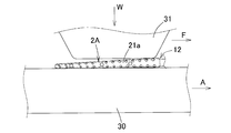
- a dynamic friction coefficient measuring device As a dynamic friction coefficient measuring device, TL201Ts manufactured by Trinity Lab Co., Ltd. is used, and as shown in FIG. 5, an interdental cleaning tool having a cleaning portion 2A obtained by cutting the protrusion 21b from the root on the moving table 30 of the measuring device.
- the surface contactor 31 of the measuring device having a contact area of 10 ⁇ 10 mm is pressed and placed so that a load W of 100 g acts on the cleaning unit 2A.
- the force F acting on the surface contact 31 when the moving table 30 was moved in the direction indicated by arrow A in FIG. 5 at a moving speed of 10 mm / sec was measured to calculate the dynamic friction coefficient.
- Table 2 shows the measurement results of the cleanability, dynamic friction coefficient, and contact angle obtained in this way.
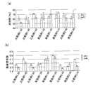
- the removal rate of the pseudo plaque in the dry state and the wet state of the interdental cleaning tool of Examples 1 and 2 and Comparative Examples 1 and 2 is shown in FIG. 7A, and Examples 1 and 2 and Comparative Examples 1 to 3 are shown.
- FIG. 7B shows dynamic friction coefficients of the interdental cleaning tool in the dry state and the wet state.
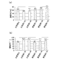
- the removal rate of the pseudo plaque in the wet state of the interdental cleaning tool of Comparative Example G, Comparative Examples 1.30, 1.40 and Example 1 is shown in FIG. 8A, and the contact angle is shown in FIG. ).
- the measurement result was obtained as an average value obtained by measuring the cleaning property, the dynamic friction coefficient, and the contact angle three times each.
- “sd” in Table 2 is a standard deviation.
- the coefficient of dynamic friction ⁇ w (wet) in the state in which the water of Comparative Examples 1, 2, and 3 using a general-purpose styrene-based thermoplastic elastomer (THERMOLLAST K (trade name) manufactured by KRAIBURG) is interposed is water.
- the styrene-based thermoplastic elastomer (THERMOLLAST W (trade name) manufactured by KRAIBURG) was used.
- the dynamic friction coefficient ⁇ w (wet) in the state where water is interposed in Examples 1 and 2 is compared with the dynamic friction coefficient ⁇ d (dry) in the state where water is not interposed as in Example 1.30.
- Example 1.40 and Example 2.40, and lower as in Example 1.50 Even if it is the same or higher as in Example 1.40 and Example 2.40, and lower as in Example 1.50, the rate of decrease is relatively small, less than 90%. It can be seen that a lower rate.
- Comparative Example 1.60 Even in the state where water is present, cleaning performance equivalent to that of Example 1.30 is obtained, but the Shore A hardness is as high as A60, and stimulation of the gums is caused during cleaning. Since it became strong, it was difficult to use as a cleaning tool.
Landscapes
- Health & Medical Sciences (AREA)
- Dentistry (AREA)
- Epidemiology (AREA)
- Life Sciences & Earth Sciences (AREA)
- Animal Behavior & Ethology (AREA)
- General Health & Medical Sciences (AREA)
- Public Health (AREA)
- Veterinary Medicine (AREA)
- Brushes (AREA)
Abstract
【課題】歯間への挿入性に優れ、しかも唾液が介在した状態での清掃性を十分に確保可能な歯間清掃具を提供する。 【解決手段】合成樹脂からなるハンドル基材11と、ハンドル基材11の細長い軸状の芯部12にエラストマからなる清掃部本体21を外装してなる清掃部2とを備え、清掃部本体21が芯部12を被覆する被覆部21aと、被覆部21aから外方へ突出する清掃用の複数の突起部21bとを有する歯間清掃具1であって、清掃部本体21をショアA硬さがA25~A55のスチレン系熱可塑性エラストマで構成し、清掃部2Aにおける、水を介在させていない状態での動摩擦係数をμd、水を介在させた状態での動摩擦係数をμwとしたときに、両動摩擦係数間に0.9×μd≦μwの関係式が成立する。
Description
本発明は、エラストマで被覆した清掃部を有する歯間清掃具に関するものである。
歯間清掃具として、合成樹脂からなるハンドル基材と、前記ハンドル基材の細長い軸状の芯部にエラストマからなる清掃部本体を外装してなる清掃部とを備え、前記清掃部本体が芯部を被覆する被覆部と、前記被覆部から外方へ突出する清掃用の複数の突起部とを有する歯間清掃具が実用化されている(例えば、特許文献1参照。)。
前記歯間清掃具は、合成樹脂製フィラメントを金属線材に対して放射状に植設してなる清掃部を有する従来の歯間ブラシと比較して、突起部の剛性が極端に小さいため、歯間清掃具の清掃性は、清掃部本体におけるエラストマの表面特性(動摩擦係数)の影響を受けて大きく変動する。しかし、エラストマからなる清掃部本体を用いる歯間清掃具自体が、比較的新しい技術であることから、動摩擦係数を用いた清掃性の評価は、まだ実施されていないのが実状である。
本出願人は、前記特許文献1記載の歯間清掃具では、水が介在した場合、即ち歯間清掃時に唾液が介在した場合に、エラストマからなる清掃部の動摩擦係数が低下して、清掃性が低下するという問題が発生していることを見出した。
本発明の目的は、歯間への挿入性に優れ、しかも唾液が介在した状態での清掃性を十分に確保可能な歯間清掃具を提供することである。
本発明に係る歯間清掃具は、合成樹脂からなるハンドル基材と、前記ハンドル基材の細長い軸状の芯部にエラストマからなる清掃部本体を外装してなる清掃部とを備え、前記清掃部本体が芯部を被覆する被覆部と、前記被覆部から外方へ突出する清掃用の複数の突起部とを有する歯間清掃具であって、前記清掃部本体をショアA硬さがA25~A55のスチレン系熱可塑性エラストマで構成し、前記清掃部における、水を介在させていない状態での動摩擦係数をμd、水を介在させた状態での動摩擦係数をμwとしたときに、両動摩擦係数間に0.9×μd≦μwの関係式が成立するものである。
この歯間清掃具では、清掃部における、水を介在させていない状態での動摩擦係数をμd、水を介在させた状態での動摩擦係数をμwとしたときに、0.9×μd≦μwの関係式が成立するので、歯間清掃時に清掃部本体が唾液で濡れたときに、清掃部本体の動摩擦係数が、濡れていないときと比較して、高くなるか、低くなる場合でも、濡れていないときの90%以上の動摩擦係数になるので、清掃性を高めることができる。
ここで、前記被覆部が芯部の先端部まで形成されていることが好ましい実施の形態である。このように構成すると、歯間への挿入時に清掃部の先端部が歯肉に当たった場合でも、歯肉を傷つけるという不具合を効果的に防止できる。
また、歯間の清掃性を十分に確保するため、前記清掃部の先端部の中心と、清掃部の先端から10mmの位置での被覆部の外周縁とを結ぶ線分をL1とし、前記清掃部の先端部の中心と、最も基端側の突起部の先端部とを結ぶ線分をL2とし、前記線分L1と清掃部の中心線CLとのなす角度θ1と、前記線分L2と清掃部の中心線CLとのなす角度θ2との角度差(θ2-θ1)を3.0°~7.5°に設定することが好ましい実施の形態である。
更に、前記清掃部の最基端部から3本の突起部の平均高さを0.7mm~2.3mm、好ましくは0.8mm~2.0 mmに設定することも、清掃性を十分に確保する上で好ましい実施の形態である。
前記エラストマの水に対する接触角は、65°~95°、好ましくは70°~95°、より好ましくは75°~95°に設定することが望ましい。接触角をこのような数値範囲に設定することで、清掃性を向上できる。
本発明に係る歯間清掃具によれば、清掃部における、水を介在させていない状態での動摩擦係数をμd、水を介在させた状態での動摩擦係数をμwとしたときに、0.9×μd≦μwの関係式が成立するので、歯間清掃時に清掃部本体が唾液で濡れたときに、清掃部本体の動摩擦係数が、濡れていないときと比較して、高くなるか、低くなる場合でも、濡れていないときの90%以上の動摩擦係数になるので、清掃性を高めることができる。
以下、本発明の実施の形態について図面を参照しながら説明する。
図1~図4に示すように、歯間清掃具1は、その機能で区別すると、歯間清掃用の清掃部2と、持ち手としてのハンドル部3とを備え、その素材で区別すると、合成樹脂からなる基材部10と、エラストマからなる軟質部20とを備えており、基材部10に一体的に設けた1対の連結部13を介して切り離し可能に並列状に複数個連結されている。ただし、連結部13を省略して、歯間清掃具1を独立に構成することも可能である。
図1~図4に示すように、歯間清掃具1は、その機能で区別すると、歯間清掃用の清掃部2と、持ち手としてのハンドル部3とを備え、その素材で区別すると、合成樹脂からなる基材部10と、エラストマからなる軟質部20とを備えており、基材部10に一体的に設けた1対の連結部13を介して切り離し可能に並列状に複数個連結されている。ただし、連結部13を省略して、歯間清掃具1を独立に構成することも可能である。
(基材部)
合成樹脂からなる基材部10は、図1~図4に示すように、ハンドル部3を構成する扁平な細長い板状のハンドル基材11と、ハンドル基材11の先端部に連設した細長い軸状の芯部12とを備えている。
合成樹脂からなる基材部10は、図1~図4に示すように、ハンドル部3を構成する扁平な細長い板状のハンドル基材11と、ハンドル基材11の先端部に連設した細長い軸状の芯部12とを備えている。
ハンドル基材11は、扁平な細長い板状に形成したが、手で保持して歯間を清掃し易い形状であれば、扁平な細長い板状以外の任意の形状、例えば円形や楕円形や多角形などの横断面形状の棒状に形成することもできる。
芯部12は、略直線状の細長い軸状に形成され、芯部12の基部側は外部に露出する露出部12aが形成され、芯部12の先端側部分にはエラストマが被覆されて歯間に挿入可能な芯本体12bが形成され、芯部12は先端側へ行くにしたがって縮径する緩やかなテーパ形状に形成されている。露出部12aの長さは操作性を考慮して、例えば25mm~50mmに設定され、芯本体12bの長さは歯間に対する清掃性を考慮して、例えば12mm~22mmに設定されている。芯部12の長さ方向に対するテーパ形状のなす角度θは、歯間への挿入性を考慮して、0.2°~1.5°に設定されている。芯本体12bの先端側部分の直径は0.4mm~0.6mmに設定され、芯本体12bの基部の直径は0.8mm~2.0mmに設定され、芯本体12bの先端部から少なくとも5mm以上の芯本体12bの先端側部分を確実に歯間に挿入できるように構成されている。ただし、芯部12のテーパ形状のなす角度θは、芯部12の全長にわたって同じ角度θに設定したが、芯部12の先端側へ行くにしたがって連続的或いは段階的に小さくなるように設定することもできる。また、露出部12aを全長にわたって同じ直径の軸状に形成し、芯本体12bのみを先端側へ行くにしたがって縮径する緩やかなテーパ形状に形成することもできる。更に、露出部12aを省略し、芯本体12bをハンドル基材11に直接的に連設することも可能である。
基材部10を構成する合成樹脂材料としては、ポリプロピレン、ポリエチレン、ポリエチレンテレフタレート、ポリシクロヘキシレンジメチレンテレフタレート、飽和ポリエステル樹脂、ポリメタクリル酸メチル、プロピオン酸セルロース、ポリウレタン、ポリアミド、ポリカーボネート、ABS(アクリロニトリル・ブタジエン・スチレン)などの熱可塑性合成樹脂材料を採用できる。特に、ポリプロピレンは、清掃部本体21を構成するスチレン系熱可塑性エラストマとの相溶性を有し、成形温度が低く、サイクルタイムを短縮して生産性を向上できるとともに、成形設備に対する熱負荷が少ないことから好ましい。
また、基材部10を構成する合成樹脂材料に対して添加剤として、ガラス繊維や炭素繊維やアラミド繊維などの繊維材や、マイカやタルクなどの鉱物を添加することも好ましい。この場合には、添加剤により基材部10の寸法安定性が向上するとともに、基材部10の強度剛性が高くなって変形が防止されるので、第1金型にて成形した基材部10に軟質部20を一体成形するため、基材部10を軟質部20の成形用の第2金型に装填するときにおける装填不良を防止できる。また、添加剤により芯部12の熱変形温度が高くなるので、清掃部本体21を成形するときのエラストマ材料の熱により、芯部12が軟化して変形することを効果的に防止できるとともに、添加剤により強度剛性が高くなるので、エラストマ材料の射出圧による芯部12の変形を防止でき、清掃部本体21の成形不良を効果的に防止できる。添加剤として繊維材を添加する場合には、繊維材の配合割合は、20重量%未満の場合には曲り易くなって、清掃部2を歯間に挿入し難くなり、40重量%を超えると清掃部2が折れ易くなるので、20重量%以上、40重量%以下に設定することが好ましく、25重量%以上35重量%以下に設定することが最も好ましい。
(軟質部)
軟質部20は、図1~図4に示すように、エラストマ材料を用いて基材部10に一体成形したもので、芯部12に外装した清掃部本体21を備えている。ただし、軟質部20として、芯本体12bの基端部に歯間への挿入を規制する環状の挿入規制部を設けたり、ハンドル基材11に滑り止め部を設けたりすることも可能である。挿入規制部や滑り止め部は、清掃部本体21とは独立に成形することも可能であるが、金型構造が複雑になるので、清掃部本体21の基部に連なるように形成することが好ましい。
軟質部20は、図1~図4に示すように、エラストマ材料を用いて基材部10に一体成形したもので、芯部12に外装した清掃部本体21を備えている。ただし、軟質部20として、芯本体12bの基端部に歯間への挿入を規制する環状の挿入規制部を設けたり、ハンドル基材11に滑り止め部を設けたりすることも可能である。挿入規制部や滑り止め部は、清掃部本体21とは独立に成形することも可能であるが、金型構造が複雑になるので、清掃部本体21の基部に連なるように形成することが好ましい。
清掃部本体21は、芯部12に被覆した被覆部21aと、被覆部21aに長さ方向に間隔をあけて外方へ突出状に形成した複数の突起部21bとを有し、被覆部21aは芯部12の先端部まで設けられている。
被覆部21aの肉厚は、厚過ぎると被覆部21aの直径が大きくなって歯間への挿入性が低下し、薄過ぎると清掃部2の先端部或いは基端部までエラストマ材料を充填できないので、0.1mm~0.3mmに設定することが好ましい。
突起部21bは、被覆部21aの長さ方向に相互に間隔をあけて形成されるとともに、被覆部21aの周方向に間隔をあけて配置されている。より具体的には、被覆部21aの周方向には、被覆部21aから型開閉方向の一側方に突出する2つ1組の突起部21bと、被覆部21aから型開閉方向の他側方に突出する2つ1組の突起部21bと、被覆部21aから成形型の合わせ面に沿って一側方へ突出する1つの突起部21bと、被覆部21aから成形型の合わせ面に沿って他側方へ突出する1つの突起部21bの計6種類の突起部21bが配置され、これら6種類の突起部21bが被覆部21aの長さ方向に相互に間隔をあけて複数組形成されている。ただし、突起部21bは、上述した以外の配列パターンで形成することも可能である。
突起部21bの基端部の断面積や長さ、個数や配設ピッチは、任意に設定可能であるが、成形性及び清掃性を考慮して、突起部21bの基端部の断面積は、0.03mm2~1.5mm2程度に設定することが好ましく、突起部21bの長さは0.5mm~2.0mm程度に設定することが好ましく、突起部21bの個数は20個~100個に設定することが好ましく、突起部21bの配設ピッチは0.5mm~1.5mmに設定することが好ましい。また、突起部21bとして、円錐状のものを採用したが、軸方向に扁平な平板状の先細形状のものを採用することもできる。更に、突起部21bの断面形状としては、円形以外に、楕円形や多角形などの任意の断面形状のものを採用できる。
本発明は、清掃部本体21を構成するエラストマとして、ショアA硬さがA25~A55のスチレン系熱可塑性エラストマであって、図5に示すように、突起部21bを根元から切除した状態での清掃部2A(被覆部21a)における、水を介在させていない状態での動摩擦係数をμd、水を介在させた状態での動摩擦係数をμwとしたときに、両動摩擦係数間に0.9×μd≦μwの関係式が成立するエラストマを用いたことを特徴とする。なお、ショアA硬さは、A25未満の場合には、柔らかすぎて清掃性が低下し、A55を超えると、硬すぎて歯肉への刺激が強くなるので、A25~A55に設定することが好ましい。
具体的には、清掃部本体21を構成するエラストマとして、KRAIBURG社製のTHERMOLAST W(商品名)を採用することができる。つまり、歯間清掃具1において、清掃部本体21に汎用のエラストマを使用すると、水に濡れることで、清掃部本体21の動摩擦係数が大幅に低下するが、エラストマとしてKRAIBURG社製のTHERMOLAST W(商品名)を使用すると、水に濡れることで、水に濡れていないときよりも、動摩擦係数が高くなるか、低くなる場合でも、水で濡れていないときの90%以上の動摩擦係数になり、大幅な動摩擦係数の低下が抑制されるので、歯間清掃時に清掃部本体21が唾液で濡れたときにおける、清掃部本体21の動摩擦係数を十分に確保して、歯間清掃具1の清掃性を向上できる。また、水が介在していないとき、即ち清掃部本体21が唾液で濡れていないときには、動摩擦係数が低くなるので、歯間清掃具1の歯間への挿入性を高めることができる。
また、歯間に対する清掃性を十分に確保するため、清掃部2の先端部の中心と、清掃部2の先端から10mmの位置での被覆部21aの外周縁とを結ぶ線分をL1とし、最基端部の突起部21bと、最基端部から2番目及び3番目の突起部21bの合計3つの突起部21bの高さの平均値を求め、その平均値の高さを有する突起部が、最基端部に存在すると仮定した時の該最基端部の仮想突起部の先端部と、清掃部2の先端部の中心とを結ぶ線分をL2とし、線分L1と清掃部2の中心線CLとのなす角度θ1と、線分L2と清掃部2の中心線CLとのなす角度θ2との角度差(θ2-θ1)を3.0°~7.5°に設定することが好ましい。つまり、角度差(θ2-θ1)が大きい程、水の介在の有無による動摩擦係数の低下が少ないか、或いは増加する傾向があるため、角度差(θ2-θ1)は少なくとも3.0°以上が好ましい。また、角度差(θ2-θ1)が7.5°よりも大きいと、使用時に突起部21bが切断される可能性があるため、7.5°以下に設定することが好ましい。また、清掃部2の最基端部から3本の突起部21bの平均高さを0.7mm~2.3mm、好ましくは0.8mm~2.0mmに設定することが好ましい。
更に、清掃部本体21を構成するエラストマとして、スチレン系熱可塑性エラストマであって、水に対する接触角θ3が、65°~95°、好ましくは70°~95°、より好ましくは75°~95°のものが、清掃性を向上できるので好ましい。なお、接触角θ3とは、図6に示すように、液体を平坦な固体表面Sに滴下したときに、固体表面Sに形成される液滴Liにおける、固体表面S位置における液滴表面の接線L3と、固体表面Sとのなす角度を意味し、接触角θ3が大きくなるにしたがって、液体に対して濡れにくい物性となる。
次に、歯間清掃具の評価試験について説明する。
実施例1の歯間清掃具として、図1~図4に示す構成の歯間清掃具1であって、清掃部2の長さが15.5mm、芯部の基部の直径が1.0mm、角度θ1が3.2°、角度θ2が6.4°、基端部からの3本の突起部の平均高さが0.8mmであり、基材部10をポリプロピレンで構成し、軟質部20をショアA硬さがA30、A40、A50になるように成分調整したスチレン系熱可塑性エラストマ(KRAIBURG社製のTHERMOLAST W(商品名))で構成してなる、実施例1.30、実施例1.40、実施例1.50の3種類の歯間清掃具を製作した。
実施例1の歯間清掃具として、図1~図4に示す構成の歯間清掃具1であって、清掃部2の長さが15.5mm、芯部の基部の直径が1.0mm、角度θ1が3.2°、角度θ2が6.4°、基端部からの3本の突起部の平均高さが0.8mmであり、基材部10をポリプロピレンで構成し、軟質部20をショアA硬さがA30、A40、A50になるように成分調整したスチレン系熱可塑性エラストマ(KRAIBURG社製のTHERMOLAST W(商品名))で構成してなる、実施例1.30、実施例1.40、実施例1.50の3種類の歯間清掃具を製作した。
実施例2の歯間清掃具として、角度θ1を3.6°、角度θ2を8.4°、最基端部から3本の突起部の平均高さを1.5mmに設定した以外は、実施例1.40と同様に構成してなる、軟質部20のショアA硬さがA40の実施例2.40の歯間清掃具を製作した。
比較例1の歯間清掃具として、軟質部20をショアA硬さがA30、A40、A60になるように成分調整した汎用のスチレン系熱可塑性エラストマ(KRAIBURG社製のTHERMOLAST K(商品名))で構成した以外は、実施例1と同様に構成してなる、比較例1.30、比較例1.40、比較例1.60の3種類の歯間清掃具を製作した。
比較例2の歯間清掃具として、軟質部20をショアA硬さがA40になるように成分調整した汎用のスチレン系熱可塑性エラストマ(KRAIBURG社製のTHERMOLAST K(商品名))で構成した以外は、実施例2.40と同様に構成してなる、比較例2.40の歯間清掃具を製作した。
比較例3の歯間清掃具として、角度θ1を4.1°、角度θ2を11.3°、最基端部から3本の突起部の平均高さを2.0mmに設定し、軟質部20のショアA硬さがA30になるように成分調整した汎用のスチレン系熱可塑性エラストマ(KRAIBURG社製のTHERMOLAST K(商品名))で構成した以外は、実施例1.30と同様に構成してなる比較例3.30の歯間清掃具を製作した。
比較例Gの歯間清掃具として、ナイロン製の複数のフィラメントを金属線に放射状に保持させた、サンスター株式会社製のG・U・M I字型SSSサイズの歯間ブラシを用いた。
表1に、実施例1、2及び比較例1~3における最基端部の突起部の高さと、最基端部から2番目の突起部の高さと、最基端部から3番目の突起部の高さと、これら3つの突起部の平均高さをまとめて示す。

そして、上述のようにして製作した実施例及び比較例の歯間清掃具における、歯間に対する清掃性と、動摩擦係数と、接触角とを次のようにして測定した。
(清掃性)
実施例1及び2、比較例1、2の歯間清掃具について、清掃部が乾いている場合、即ち水が介在していない状態での清掃性(dry)と、清掃部を水に浸して、清掃部が水で濡れている場合、即ち水が介在している状態での清掃性(wet)を、次のようにして測定した。また、比較例Gに関しては、清掃部を水に浸して、清掃部が水で濡れている場合、即ち水が介在している状態での清掃性(wet)についてのみ測定した。
実施例1及び2、比較例1、2の歯間清掃具について、清掃部が乾いている場合、即ち水が介在していない状態での清掃性(dry)と、清掃部を水に浸して、清掃部が水で濡れている場合、即ち水が介在している状態での清掃性(wet)を、次のようにして測定した。また、比較例Gに関しては、清掃部を水に浸して、清掃部が水で濡れている場合、即ち水が介在している状態での清掃性(wet)についてのみ測定した。
擬似歯間モデルの歯間面を形成することとなる部分に擬似プラーク(商品名「オクルード」、Pascal Company Inc.)を塗布し、実施例1及び2、比較例1、2、比較例Gの歯間清掃具にて、それぞれ擬似歯間部への挿入および引き抜きを1回ずつ行い、擬似プラークの刷掃を行った。
擬似歯間モデルの歯間幅は、ISO16409に記載の機器および手順で測定された各歯間ブラシサンプルの通過孔径+0.1mmの歯間幅を用いた。刷掃後、擬似歯間モデルの歯間面を写真撮影し、画像処理ソフト(Adobe社製Photshop)を用いた画像解析により、擬似プラークの除去率を清掃性として算出した。また、比較例G以外の歯間清掃具に関しては、清掃性の変化率(%)を、((清掃性(wet)-清掃性(dry))/清掃性(dry))×100の式で算出した。
(動摩擦係数)
実施例1及び2、比較例1~3の歯間清掃具について、その全ての突起部21bを切除した後、清掃部2Aが乾いている場合、即ち水が介在していない状態での動摩擦係数μd(dry)と、清掃部2Aを水に浸して、清掃部2Aが水で濡れている場合、即ち水が介在している状態での動摩擦係数μw(wet)を、次のようにしてそれぞれ測定した。また、動摩擦係数の変化率(%)を、((動摩擦係数(wet)-動摩擦係数(dry))/動摩擦係数(dry))×100の式で算出した。
実施例1及び2、比較例1~3の歯間清掃具について、その全ての突起部21bを切除した後、清掃部2Aが乾いている場合、即ち水が介在していない状態での動摩擦係数μd(dry)と、清掃部2Aを水に浸して、清掃部2Aが水で濡れている場合、即ち水が介在している状態での動摩擦係数μw(wet)を、次のようにしてそれぞれ測定した。また、動摩擦係数の変化率(%)を、((動摩擦係数(wet)-動摩擦係数(dry))/動摩擦係数(dry))×100の式で算出した。
動摩擦係数の測定装置として、株式会社トリニティーラボ製のTL201Tsを用い、図5に示すように、測定装置の移動テーブル30上に突起部21bを根元から切除した清掃部2Aを有する歯間清掃具を、移動テーブル30の移動方向に沿って載置固定し、接触面積10×10mmの測定装置の面接触子31を、清掃部2Aに100gの荷重Wが作用するように圧接しながら、この状態で移動テーブル30を図5に矢印Aで示す方向へ10mm/secの移動速度で移動させたときにおける、面接触子31に作用する力Fを測定して、動摩擦係数を演算した。
(接触角)
実施例1及び比較例1.30、1.40で用いた歯間清掃具の清掃部(軟質部)を構成する素材でサンプルシートを製作するとともに、比較例Gで用いた歯間清掃具の清掃部(フィラメント)を構成する素材としてのナイロンでサンプルシートを製作し、協和界面化学株式社製のFACE接触角計CA-D型を用いて、各サンプルシートの表面に水滴を形成したときにおける、サンプルシートの表面位置における水滴表面の接線と、サンプルシートの表面とのなす角度を接触角としてそれぞれ測定した。
実施例1及び比較例1.30、1.40で用いた歯間清掃具の清掃部(軟質部)を構成する素材でサンプルシートを製作するとともに、比較例Gで用いた歯間清掃具の清掃部(フィラメント)を構成する素材としてのナイロンでサンプルシートを製作し、協和界面化学株式社製のFACE接触角計CA-D型を用いて、各サンプルシートの表面に水滴を形成したときにおける、サンプルシートの表面位置における水滴表面の接線と、サンプルシートの表面とのなす角度を接触角としてそれぞれ測定した。
こうして得られた清掃性と動摩擦係数と接触角の測定結果を表2に示す。また、実施例1及び2、比較例1、2の歯間清掃具のdry状態及びwet状態における擬似プラークの除去率を図7(a)に示し、実施例1及び2、比較例1~3の歯間清掃具のdry状態及びwet状態における動摩擦係数を図7(b)に示す。更に、比較例G、比較例1.30、1.40及び実施例1の歯間清掃具のwet状態における、擬似プラークの除去率を図8(a)に示し、接触角を図8(b)に示す。ただし、前記測定結果は、清掃性と動摩擦係数と接触角の測定をそれぞれ3回ずつ行ってその平均値として求めたものである。また、表2の「s.d」は標準偏差である。
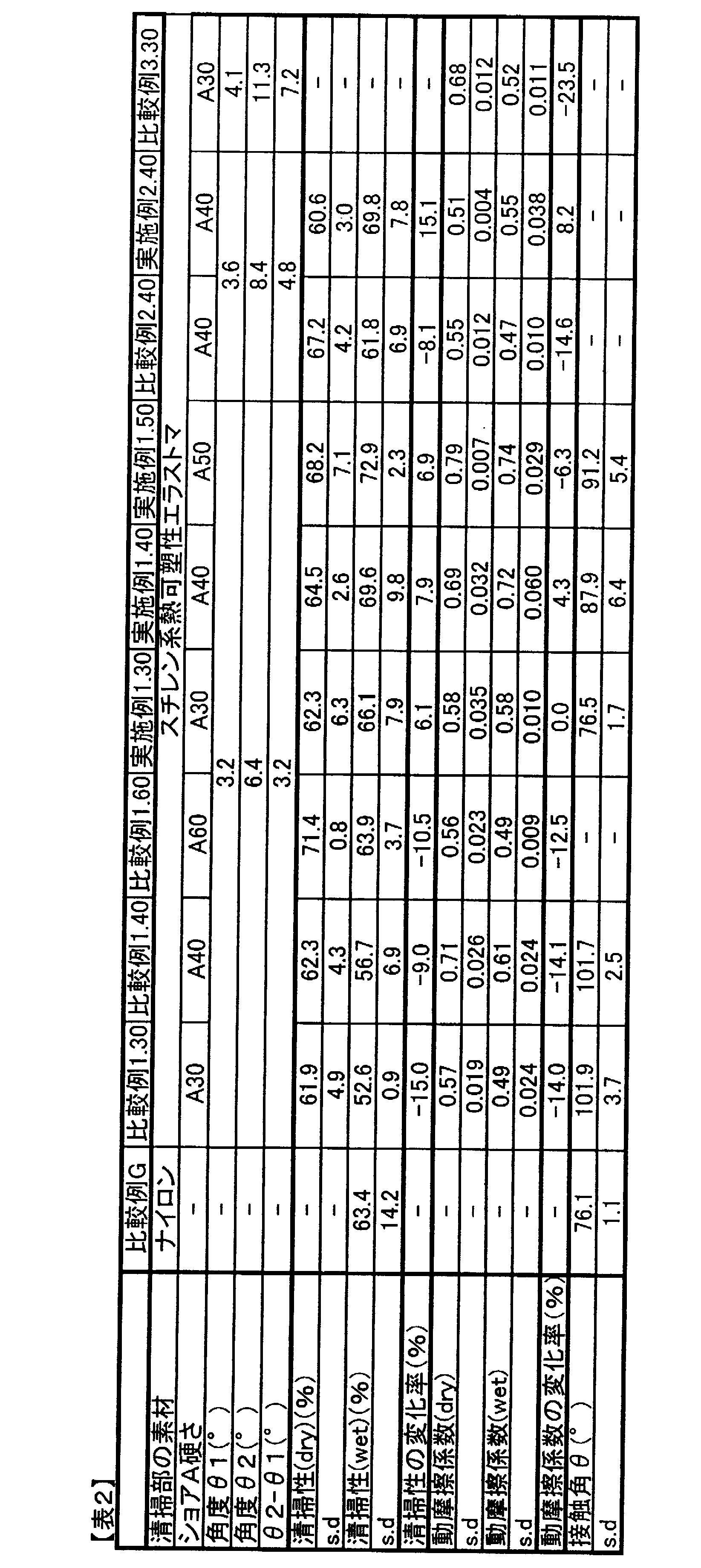
表2、図7から、清掃部2Aを構成するエラストマのショアA硬さが同じであれば、スチレン系熱可塑性エラストマ(KRAIBURG社製のTHERMOLAST W(商品名))を用いた実施例1、2の方が、汎用のスチレン系熱可塑性エラストマ(KRAIBURG社製のTHERMOLAST K(商品名))を用いた比較例1、2と比較して、水に濡れた状態での清掃性が高くなっていることが分かる。
また、汎用のスチレン系熱可塑性エラストマ(KRAIBURG社製のTHERMOLAST K(商品名))を用いた比較例1、2、3の水を介在している状態での動摩擦係数μw(wet)は、水を介在していない状態での動摩擦係数μd(dry)と比較して大幅に低下しているのに対して、スチレン系熱可塑性エラストマ(KRAIBURG社製のTHERMOLAST W(商品名))を用いた実施例1、2の水を介在している状態での動摩擦係数μw(wet)は、水を介在していない状態での動摩擦係数μd(dry)と比較して、実施例1.30のように同等、または実施例1.40及び実施例2.40のように高くなっており、実施例1.50のように、低くなっている場合でも、その低下率は90%未満の比較的小さな低下率であることが分かる。なお、比較例1.60は、水が介在している状態においても、実施例1.30と同等の清掃性が得られるが、ショアA硬さがA60と高く、清掃時に歯肉への刺激が強くなることから清掃具として使用困難であった。
更に、表2、図8から、接触角が大きくなると清掃性が低下し、接触角が小さくなると清掃性が向上する傾向にあることが分かる。また、実施例1の歯間清掃具では、比較例Gのような汎用の歯間ブラシよりも高い清掃性が得られることが分かる。
以上、本発明の実施形態について説明したが、本発明は前述した実施形態に何ら限定されるものではなく、本発明の要旨を逸脱しない範囲においてその構成を変更し得ることは勿論である。
1 歯間清掃具
2 清掃部
2A 清掃部
3 ハンドル部
10 基材部
11 ハンドル基材
12 芯部
12a 露出部
12b 芯本体
13 連結部
20 軟質部
21 清掃部本体
21a 被覆部
21b 突起部
30 移動テーブル
31 面接触子
S 固体表面
Li 液滴
2 清掃部
2A 清掃部
3 ハンドル部
10 基材部
11 ハンドル基材
12 芯部
12a 露出部
12b 芯本体
13 連結部
20 軟質部
21 清掃部本体
21a 被覆部
21b 突起部
30 移動テーブル
31 面接触子
S 固体表面
Li 液滴
Claims (3)
- 合成樹脂からなるハンドル基材と、前記ハンドル基材の細長い軸状の芯部にエラストマからなる清掃部本体を外装してなる清掃部とを備え、前記清掃部本体が芯部を被覆する被覆部と、前記被覆部から外方へ突出する清掃用の複数の突起部とを有する歯間清掃具であって、
前記清掃部本体をショアA硬さがA25~A55のスチレン系熱可塑性エラストマで構成し、
前記清掃部における、水を介在させていない状態での動摩擦係数をμd、水を介在させた状態での動摩擦係数をμwとしたときに、両動摩擦係数間に0.9×μd≦μwの関係式が成立する、
ことを特徴とする歯間清掃具。 - 前記被覆部が芯部の先端部まで形成されている請求項1記載の歯間清掃具。
- 前記エラストマの水に対する接触角を65°~95°に設定した請求項1又は2記載の歯間清掃具。
Priority Applications (1)
| Application Number | Priority Date | Filing Date | Title |
|---|---|---|---|
| JP2014543342A JPWO2014065368A1 (ja) | 2012-10-24 | 2013-10-24 | 歯間清掃具 |
Applications Claiming Priority (2)
| Application Number | Priority Date | Filing Date | Title |
|---|---|---|---|
| JP2012-234998 | 2012-10-24 | ||
| JP2012234998 | 2012-10-24 |
Publications (1)
| Publication Number | Publication Date |
|---|---|
| WO2014065368A1 true WO2014065368A1 (ja) | 2014-05-01 |
Family
ID=50544741
Family Applications (1)
| Application Number | Title | Priority Date | Filing Date |
|---|---|---|---|
| PCT/JP2013/078825 Ceased WO2014065368A1 (ja) | 2012-10-24 | 2013-10-24 | 歯間清掃具 |
Country Status (2)
| Country | Link |
|---|---|
| JP (2) | JPWO2014065368A1 (ja) |
| WO (1) | WO2014065368A1 (ja) |
Cited By (13)
| Publication number | Priority date | Publication date | Assignee | Title |
|---|---|---|---|---|
| WO2016076241A1 (ja) | 2014-11-11 | 2016-05-19 | サンスター株式会社 | 歯間清掃具 |
| WO2016113928A1 (ja) * | 2015-01-16 | 2016-07-21 | 小林製薬株式会社 | 歯間清掃具 |
| JP2016131899A (ja) * | 2016-04-04 | 2016-07-25 | 小林製薬株式会社 | 歯間清掃具 |
| JP2017000319A (ja) * | 2015-06-08 | 2017-01-05 | サンスター スイス エスエー | 歯間清掃具 |
| JP2017086775A (ja) * | 2015-11-17 | 2017-05-25 | 小林製薬株式会社 | 歯間清掃具群 |
| JP2017108998A (ja) * | 2015-12-18 | 2017-06-22 | 小林製薬株式会社 | 歯間清掃具 |
| WO2017104785A1 (ja) * | 2015-12-18 | 2017-06-22 | 小林製薬株式会社 | 歯間清掃具 |
| JP2017109019A (ja) * | 2015-12-18 | 2017-06-22 | 小林製薬株式会社 | 歯間清掃具 |
| JP2017176488A (ja) * | 2016-03-30 | 2017-10-05 | 小林製薬株式会社 | 歯間清掃具及び歯間清掃具群 |
| GB2557262A (en) * | 2016-12-02 | 2018-06-20 | Peri Dent Ltd | Apparatus for interdental cleaning and method for manufacturing the same |
| JP2018126593A (ja) * | 2018-04-25 | 2018-08-16 | 小林製薬株式会社 | 歯間清掃具 |
| WO2022004579A1 (ja) | 2020-06-30 | 2022-01-06 | 小林製薬株式会社 | 歯間清掃具 |
| USD1021416S1 (en) | 2021-03-02 | 2024-04-09 | Esro Ag | Interdental cleaner |
Citations (2)
| Publication number | Priority date | Publication date | Assignee | Title |
|---|---|---|---|---|
| JP3002668B1 (ja) * | 1998-07-14 | 2000-01-24 | 株式会社広栄社 | ブラシ楊枝 |
| JP2011529729A (ja) * | 2008-07-29 | 2011-12-15 | サンスター・アメリカズ・インコーポレイテッド | 歯間クリーナとこのような歯間クリーナを形成する方法 |
Family Cites Families (3)
| Publication number | Priority date | Publication date | Assignee | Title |
|---|---|---|---|---|
| SE452101B (sv) * | 1984-11-13 | 1987-11-16 | Leif Einar Stern | Tandpetare uppvisande ett bagformat blad |
| JP2003245287A (ja) * | 2002-02-22 | 2003-09-02 | Kao Corp | 歯間清掃用具 |
| JP5828498B2 (ja) * | 2010-11-02 | 2015-12-09 | 花王株式会社 | 歯間清掃具 |
-
2013
- 2013-10-24 WO PCT/JP2013/078825 patent/WO2014065368A1/ja not_active Ceased
- 2013-10-24 JP JP2014543342A patent/JPWO2014065368A1/ja active Pending
-
2016
- 2016-08-09 JP JP2016156251A patent/JP2016187687A/ja active Pending
Patent Citations (2)
| Publication number | Priority date | Publication date | Assignee | Title |
|---|---|---|---|---|
| JP3002668B1 (ja) * | 1998-07-14 | 2000-01-24 | 株式会社広栄社 | ブラシ楊枝 |
| JP2011529729A (ja) * | 2008-07-29 | 2011-12-15 | サンスター・アメリカズ・インコーポレイテッド | 歯間クリーナとこのような歯間クリーナを形成する方法 |
Non-Patent Citations (1)
| Title |
|---|
| "KRAIBURG TPE's Innovative Elastomer Technology", KRAIBURG TPE, 18 January 2012 (2012-01-18), Retrieved from the Internet <URL:http://www.kraiburg-tpe.com/en/news_press/archives/thermolastw> [retrieved on 20131106] * |
Cited By (26)
| Publication number | Priority date | Publication date | Assignee | Title |
|---|---|---|---|---|
| WO2016076241A1 (ja) | 2014-11-11 | 2016-05-19 | サンスター株式会社 | 歯間清掃具 |
| EP3219291A4 (en) * | 2014-11-11 | 2018-07-18 | Sunstar Inc. | Interdental cleaning tool |
| WO2016113928A1 (ja) * | 2015-01-16 | 2016-07-21 | 小林製薬株式会社 | 歯間清掃具 |
| JP2016131602A (ja) * | 2015-01-16 | 2016-07-25 | 小林製薬株式会社 | 歯間清掃具 |
| US11026771B2 (en) | 2015-01-16 | 2021-06-08 | Kobayashi Pharmaceutical Co., Ltd. | Interdental cleaning instrument |
| CN107205802B (zh) * | 2015-01-16 | 2019-09-03 | 小林制药株式会社 | 齿间清洁具 |
| US20180263741A1 (en) * | 2015-01-16 | 2018-09-20 | Kobayashi Pharmaceutical Co., Ltd. | Interdental cleaning instrument |
| CN107205802A (zh) * | 2015-01-16 | 2017-09-26 | 小林制药株式会社 | 齿间清洁具 |
| JP2017000319A (ja) * | 2015-06-08 | 2017-01-05 | サンスター スイス エスエー | 歯間清掃具 |
| JP2017086775A (ja) * | 2015-11-17 | 2017-05-25 | 小林製薬株式会社 | 歯間清掃具群 |
| WO2017086370A1 (ja) * | 2015-11-17 | 2017-05-26 | 小林製薬株式会社 | 歯間清掃具群 |
| WO2017104786A1 (ja) * | 2015-12-18 | 2017-06-22 | 小林製薬株式会社 | 歯間清掃具 |
| WO2017104784A1 (ja) * | 2015-12-18 | 2017-06-22 | 小林製薬株式会社 | 歯間清掃具 |
| JP2017109018A (ja) * | 2015-12-18 | 2017-06-22 | 小林製薬株式会社 | 歯間清掃具 |
| JP2017109019A (ja) * | 2015-12-18 | 2017-06-22 | 小林製薬株式会社 | 歯間清掃具 |
| CN108366849A (zh) * | 2015-12-18 | 2018-08-03 | 小林制药株式会社 | 齿间清洁工具 |
| US11478341B2 (en) | 2015-12-18 | 2022-10-25 | Kobayashi Pharmaceutical Co., Ltd. | Interdental cleaning tool |
| WO2017104785A1 (ja) * | 2015-12-18 | 2017-06-22 | 小林製薬株式会社 | 歯間清掃具 |
| US20190000598A1 (en) * | 2015-12-18 | 2019-01-03 | Kobayashi Pharmaceutical Co., Ltd. | Interdental cleaning tool |
| JP2017108998A (ja) * | 2015-12-18 | 2017-06-22 | 小林製薬株式会社 | 歯間清掃具 |
| JP2017176488A (ja) * | 2016-03-30 | 2017-10-05 | 小林製薬株式会社 | 歯間清掃具及び歯間清掃具群 |
| JP2016131899A (ja) * | 2016-04-04 | 2016-07-25 | 小林製薬株式会社 | 歯間清掃具 |
| GB2557262A (en) * | 2016-12-02 | 2018-06-20 | Peri Dent Ltd | Apparatus for interdental cleaning and method for manufacturing the same |
| JP2018126593A (ja) * | 2018-04-25 | 2018-08-16 | 小林製薬株式会社 | 歯間清掃具 |
| WO2022004579A1 (ja) | 2020-06-30 | 2022-01-06 | 小林製薬株式会社 | 歯間清掃具 |
| USD1021416S1 (en) | 2021-03-02 | 2024-04-09 | Esro Ag | Interdental cleaner |
Also Published As
| Publication number | Publication date |
|---|---|
| JP2016187687A (ja) | 2016-11-04 |
| JPWO2014065368A1 (ja) | 2016-09-08 |
Similar Documents
| Publication | Publication Date | Title |
|---|---|---|
| JP2016187687A (ja) | 歯間清掃具 | |
| EP3487358B1 (en) | Oral care implement and filament for the same | |
| JP5929346B2 (ja) | 歯間清掃具の製造方法 | |
| JP6619699B2 (ja) | 歯間清掃具の製造方法及び歯間清掃具 | |
| JP6339692B2 (ja) | 歯間クリーナ | |
| JP5977262B2 (ja) | 口又は歯清浄器具 | |
| WO2016199835A1 (ja) | 歯間清掃具 | |
| JP6292246B2 (ja) | 歯間清掃具 | |
| JP5386259B2 (ja) | 歯ブラシ | |
| JP6750328B2 (ja) | 歯間清掃具 | |
| JP2017000775A (ja) | 歯間清掃具 | |
| JP7339490B2 (ja) | 歯間清掃具 | |
| JP2019188013A (ja) | 歯間清掃具 | |
| EP2564808B1 (en) | Interdental cleaning member and method for manufacturing same | |
| CN105188475A (zh) | 由塑料制成的单纤丝和由相应单纤丝制成的牙刷毛 | |
| JP6750329B2 (ja) | 歯間清掃具 | |
| JP7188077B2 (ja) | 歯間清掃具 | |
| JP4547891B2 (ja) | フェザードフィラメント歯ブラシ | |
| KR102319783B1 (ko) | 칫솔 | |
| JP2015037496A (ja) | 歯ブラシの用毛及び歯ブラシ | |
| JP2017000570A (ja) | 歯間清掃具 | |
| JP5323182B2 (ja) | 歯間ブラシ及びその製造方法 | |
| JP7565672B2 (ja) | 歯間清掃具 | |
| JP2010162417A (ja) | フェザードフィラメント歯ブラシの製造方法 | |
| JP5322251B1 (ja) | 取っ手付き金属たわし(2) |
Legal Events
| Date | Code | Title | Description |
|---|---|---|---|
| 121 | Ep: the epo has been informed by wipo that ep was designated in this application |
Ref document number: 13849731 Country of ref document: EP Kind code of ref document: A1 |
|
| ENP | Entry into the national phase |
Ref document number: 2014543342 Country of ref document: JP Kind code of ref document: A |
|
| NENP | Non-entry into the national phase |
Ref country code: DE |
|
| 122 | Ep: pct application non-entry in european phase |
Ref document number: 13849731 Country of ref document: EP Kind code of ref document: A1 |