WO2014065360A1 - ファイバレーザ加工機、ファイバ接続方法及びファイバレーザ発振器 - Google Patents
ファイバレーザ加工機、ファイバ接続方法及びファイバレーザ発振器 Download PDFInfo
- Publication number
- WO2014065360A1 WO2014065360A1 PCT/JP2013/078802 JP2013078802W WO2014065360A1 WO 2014065360 A1 WO2014065360 A1 WO 2014065360A1 JP 2013078802 W JP2013078802 W JP 2013078802W WO 2014065360 A1 WO2014065360 A1 WO 2014065360A1
- Authority
- WO
- WIPO (PCT)
- Prior art keywords
- fiber
- fiber cable
- laser
- processing machine
- feeding
- Prior art date
- Legal status (The legal status is an assumption and is not a legal conclusion. Google has not performed a legal analysis and makes no representation as to the accuracy of the status listed.)
- Ceased
Links
Images





Classifications
-
- B—PERFORMING OPERATIONS; TRANSPORTING
- B23—MACHINE TOOLS; METAL-WORKING NOT OTHERWISE PROVIDED FOR
- B23K—SOLDERING OR UNSOLDERING; WELDING; CLADDING OR PLATING BY SOLDERING OR WELDING; CUTTING BY APPLYING HEAT LOCALLY, e.g. FLAME CUTTING; WORKING BY LASER BEAM
- B23K26/00—Working by laser beam, e.g. welding, cutting or boring
- B23K26/36—Removing material
- B23K26/38—Removing material by boring or cutting
-
- B—PERFORMING OPERATIONS; TRANSPORTING
- B23—MACHINE TOOLS; METAL-WORKING NOT OTHERWISE PROVIDED FOR
- B23K—SOLDERING OR UNSOLDERING; WELDING; CLADDING OR PLATING BY SOLDERING OR WELDING; CUTTING BY APPLYING HEAT LOCALLY, e.g. FLAME CUTTING; WORKING BY LASER BEAM
- B23K26/00—Working by laser beam, e.g. welding, cutting or boring
- B23K26/02—Positioning or observing the workpiece, e.g. with respect to the point of impact; Aligning, aiming or focusing the laser beam
- B23K26/06—Shaping the laser beam, e.g. by masks or multi-focusing
-
- B—PERFORMING OPERATIONS; TRANSPORTING
- B23—MACHINE TOOLS; METAL-WORKING NOT OTHERWISE PROVIDED FOR
- B23K—SOLDERING OR UNSOLDERING; WELDING; CLADDING OR PLATING BY SOLDERING OR WELDING; CUTTING BY APPLYING HEAT LOCALLY, e.g. FLAME CUTTING; WORKING BY LASER BEAM
- B23K26/00—Working by laser beam, e.g. welding, cutting or boring
- B23K26/08—Devices involving relative movement between laser beam and workpiece
- B23K26/0869—Devices involving movement of the laser head in at least one axial direction
- B23K26/0876—Devices involving movement of the laser head in at least one axial direction in at least two axial directions
- B23K26/0884—Devices involving movement of the laser head in at least one axial direction in at least two axial directions in at least three axial directions, e.g. manipulators, robots
-
- B—PERFORMING OPERATIONS; TRANSPORTING
- B23—MACHINE TOOLS; METAL-WORKING NOT OTHERWISE PROVIDED FOR
- B23K—SOLDERING OR UNSOLDERING; WELDING; CLADDING OR PLATING BY SOLDERING OR WELDING; CUTTING BY APPLYING HEAT LOCALLY, e.g. FLAME CUTTING; WORKING BY LASER BEAM
- B23K26/00—Working by laser beam, e.g. welding, cutting or boring
- B23K26/14—Working by laser beam, e.g. welding, cutting or boring using a fluid stream, e.g. a jet of gas, in conjunction with the laser beam; Nozzles therefor
-
- B—PERFORMING OPERATIONS; TRANSPORTING
- B23—MACHINE TOOLS; METAL-WORKING NOT OTHERWISE PROVIDED FOR
- B23K—SOLDERING OR UNSOLDERING; WELDING; CLADDING OR PLATING BY SOLDERING OR WELDING; CUTTING BY APPLYING HEAT LOCALLY, e.g. FLAME CUTTING; WORKING BY LASER BEAM
- B23K26/00—Working by laser beam, e.g. welding, cutting or boring
- B23K26/14—Working by laser beam, e.g. welding, cutting or boring using a fluid stream, e.g. a jet of gas, in conjunction with the laser beam; Nozzles therefor
- B23K26/1462—Nozzles; Features related to nozzles
- B23K26/1464—Supply to, or discharge from, nozzles of media, e.g. gas, powder, wire
- B23K26/147—Features outside the nozzle for feeding the fluid stream towards the workpiece
-
- B—PERFORMING OPERATIONS; TRANSPORTING
- B23—MACHINE TOOLS; METAL-WORKING NOT OTHERWISE PROVIDED FOR
- B23K—SOLDERING OR UNSOLDERING; WELDING; CLADDING OR PLATING BY SOLDERING OR WELDING; CUTTING BY APPLYING HEAT LOCALLY, e.g. FLAME CUTTING; WORKING BY LASER BEAM
- B23K26/00—Working by laser beam, e.g. welding, cutting or boring
- B23K26/36—Removing material
- B23K26/40—Removing material taking account of the properties of the material involved
-
- B—PERFORMING OPERATIONS; TRANSPORTING
- B23—MACHINE TOOLS; METAL-WORKING NOT OTHERWISE PROVIDED FOR
- B23K—SOLDERING OR UNSOLDERING; WELDING; CLADDING OR PLATING BY SOLDERING OR WELDING; CUTTING BY APPLYING HEAT LOCALLY, e.g. FLAME CUTTING; WORKING BY LASER BEAM
- B23K26/00—Working by laser beam, e.g. welding, cutting or boring
- B23K26/70—Auxiliary operations or equipment
- B23K26/702—Auxiliary equipment
- B23K26/706—Protective screens
-
- B—PERFORMING OPERATIONS; TRANSPORTING
- B23—MACHINE TOOLS; METAL-WORKING NOT OTHERWISE PROVIDED FOR
- B23K—SOLDERING OR UNSOLDERING; WELDING; CLADDING OR PLATING BY SOLDERING OR WELDING; CUTTING BY APPLYING HEAT LOCALLY, e.g. FLAME CUTTING; WORKING BY LASER BEAM
- B23K37/00—Auxiliary devices or processes, not specially adapted for a procedure covered by only one of the other main groups of this subclass
- B23K37/006—Safety devices for welding or cutting
-
- B—PERFORMING OPERATIONS; TRANSPORTING
- B23—MACHINE TOOLS; METAL-WORKING NOT OTHERWISE PROVIDED FOR
- B23K—SOLDERING OR UNSOLDERING; WELDING; CLADDING OR PLATING BY SOLDERING OR WELDING; CUTTING BY APPLYING HEAT LOCALLY, e.g. FLAME CUTTING; WORKING BY LASER BEAM
- B23K37/00—Auxiliary devices or processes, not specially adapted for a procedure covered by only one of the other main groups of this subclass
- B23K37/04—Auxiliary devices or processes, not specially adapted for a procedure covered by only one of the other main groups of this subclass for holding or positioning work
- B23K37/0408—Auxiliary devices or processes, not specially adapted for a procedure covered by only one of the other main groups of this subclass for holding or positioning work for planar work
-
- G—PHYSICS
- G02—OPTICS
- G02B—OPTICAL ELEMENTS, SYSTEMS OR APPARATUS
- G02B6/00—Light guides; Structural details of arrangements comprising light guides and other optical elements, e.g. couplings
- G02B6/24—Coupling light guides
- G02B6/42—Coupling light guides with opto-electronic elements
- G02B6/4296—Coupling light guides with opto-electronic elements coupling with sources of high radiant energy, e.g. high power lasers, high temperature light sources
-
- B—PERFORMING OPERATIONS; TRANSPORTING
- B23—MACHINE TOOLS; METAL-WORKING NOT OTHERWISE PROVIDED FOR
- B23K—SOLDERING OR UNSOLDERING; WELDING; CLADDING OR PLATING BY SOLDERING OR WELDING; CUTTING BY APPLYING HEAT LOCALLY, e.g. FLAME CUTTING; WORKING BY LASER BEAM
- B23K2101/00—Articles made by soldering, welding or cutting
- B23K2101/18—Sheet panels
-
- B—PERFORMING OPERATIONS; TRANSPORTING
- B23—MACHINE TOOLS; METAL-WORKING NOT OTHERWISE PROVIDED FOR
- B23K—SOLDERING OR UNSOLDERING; WELDING; CLADDING OR PLATING BY SOLDERING OR WELDING; CUTTING BY APPLYING HEAT LOCALLY, e.g. FLAME CUTTING; WORKING BY LASER BEAM
- B23K2103/00—Materials to be soldered, welded or cut
- B23K2103/02—Iron or ferrous alloys
- B23K2103/04—Steel or steel alloys
- B23K2103/05—Stainless steel
-
- B—PERFORMING OPERATIONS; TRANSPORTING
- B23—MACHINE TOOLS; METAL-WORKING NOT OTHERWISE PROVIDED FOR
- B23K—SOLDERING OR UNSOLDERING; WELDING; CLADDING OR PLATING BY SOLDERING OR WELDING; CUTTING BY APPLYING HEAT LOCALLY, e.g. FLAME CUTTING; WORKING BY LASER BEAM
- B23K2103/00—Materials to be soldered, welded or cut
- B23K2103/50—Inorganic materials other than metals or composite materials
-
- G—PHYSICS
- G02—OPTICS
- G02B—OPTICAL ELEMENTS, SYSTEMS OR APPARATUS
- G02B6/00—Light guides; Structural details of arrangements comprising light guides and other optical elements, e.g. couplings
- G02B6/24—Coupling light guides
- G02B6/255—Splicing of light guides, e.g. by fusion or bonding
Definitions
- the present invention relates to a fiber laser processing machine, a fiber connection method used for the fiber laser processing machine, and a fiber laser oscillator.
- a fiber laser processing machine is a device that performs processing such as cutting of a workpiece by irradiating the workpiece with laser light.
- a fiber laser oscillator includes a plurality of fiber laser modules that generate laser light, and a feeding fiber cable that collectively extracts laser light generated by the plurality of fiber laser modules.
- a coupling fiber cable is connected via a coupling unit to a process fiber cable that transmits laser light to the machining head.
- Patent Document 1 discloses a feeding fiber cable and a process in which a laser beam emission end of a feeding fiber cable and a laser beam incidence end of a process fiber cable face each other with a predetermined gap therebetween. It has been proposed to fix a fiber cable in a cylinder made of glass.
- the core diameter of the feeding fiber cable is about 50 ⁇ m
- the core diameter of the process fiber cable is about 100 to 200 ⁇ m, which is thicker than the core diameter of the feeding fiber cable.
- Patent Document 1 when the feeding fiber cable and the process fiber cable are fused, the core shape of these cables is distorted in the portion where heat is applied during the fusion, and the beam quality is deteriorated and realistically. It is described that it cannot be used.
- the present invention has been made in view of the above-described problems, and an object thereof is to provide a fiber laser processing machine, a fiber connection method, and a fiber laser oscillator capable of improving beam quality.
- the present inventor first examined increasing the power density PD (linear density) expressed by the following equation (a), which is proportional to the cutting speed, in order to increase the cutting speed of the fiber laser processing machine.
- PD P / (d ⁇ ⁇ ) (a)
- P is an output
- d is a spot system (focal diameter)
- the power density PD indicates the power per unit area.
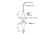
- FIG. 13 is a schematic diagram schematically showing the external optical system.
- ⁇ and ⁇ are coefficients, M is the laser divergence angle (beam mode), ⁇ is the wavelength of the laser, fL is the focal length of the condenser lens, and fC is the focal length of the collimator.
- the present inventor has studied to reduce the laser divergence angle M, which is also called a beam mode, in order to reduce the spot diameter d.
- the core diameter of the feeding fiber cable is about 50 ⁇ m
- the core diameter of the process fiber cable is about 100 to 200 ⁇ m, which is thicker than the core diameter of the feeding fiber cable. Therefore, it has not been assumed to make the core diameter of the process fiber cable smaller than 100 ⁇ m. Further, the fusion between the feeding fiber cable and the process fiber cable has not been recognized as a realistic connection method.
- the present invention realizes an improvement in beam quality by fusion of a feeding fiber cable and a process fiber cable, which has been conventionally considered to be unrealistic, and provides the following aspects.
- a processing machine body provided with a laser processing head for irradiating laser light;
- a fiber laser module having a fiber laser module for generating laser light and a feeding fiber cable for collectively extracting laser light generated by the fiber laser module;
- a process fiber cable for transmitting laser light extracted by a feeding fiber cable of the fiber laser oscillator to a laser processing head of the processing machine body, and a fiber laser processing machine comprising:
- the feeding fiber cable and the process fiber cable are joined by fusion,
- a fiber laser processing machine characterized in that the core diameters of the feeding fiber cable and the process fiber cable are equal.
- the fiber laser processing machine according to (1), wherein each of the feeding fiber cable and the process fiber cable has a uniform core diameter.
- the fiber laser oscillator includes a housing that houses the fiber laser module and the feeding fiber cable, (1) or (2), wherein the fusion part between the feeding fiber cable and the process fiber cable is arranged on a drawable fusion table accommodated in the housing.
- the processing machine body includes a cabin that houses the laser processing head and forms the outer shape of the processing machine body, The cabin has an oscillator accommodating portion that accommodates the fiber laser oscillator on a side surface, and the fiber laser oscillator is accommodated in the state of the casing in the oscillator accommodating portion. Fiber laser processing machine.
- a fiber laser module that has a fiber laser module that generates laser light, a feeding fiber cable that collectively extracts laser light generated by the fiber laser module, and a laser processing head that converts the laser light extracted by the feeding fiber cable
- a fiber connection method for connecting the feeding fiber cable and the process fiber cable used in a fiber laser processing machine comprising a process fiber cable for transmission to A fiber connecting method, comprising: fusing on a drawable fusing table provided in a housing of the fiber laser oscillator.
- a fiber laser module for generating laser light
- a feeding fiber cable that collectively extracts the laser light generated by the fiber laser module
- a housing for housing the fiber laser module and the feeding fiber cable
- a fiber laser oscillator connected to a process fiber cable for transmitting laser light to a laser processing head, The feeding fiber cable and the process fiber cable are joined by fusion,
- a process fiber cable having a core diameter equal to the core diameter of the feeding fiber cable can be used by connecting the feeding fiber cable and the process fiber cable by fusion.
- a decrease in luminance due to a difference in core diameter can be suppressed, and beam quality can be improved.
- the core diameter of the process fiber cable can be made smaller than before by fusing, and the laser divergence angle (BPP: Beam Parameter Product), also called a beam mode, can be reduced and the cutting speed can be increased. be able to.
- BPP Beam Parameter Product
- the fusion process between the feeding fiber cable and the process fiber cable is facilitated.
- the fusing process performed in a clean room such as a factory can be performed at the assembly place of the fiber laser processing machine or the installation place of the fiber laser processing machine.
- the fusing process can be easily performed by pulling out the fusing table from the housing of the fiber laser oscillator.
- the fiber laser oscillator is better than the case where the fiber laser oscillator is installed apart from the fiber laser processing machine main body and can be accommodated in the cabin of the processing machine main body. The whole can be reduced in size. Further, the fiber laser oscillator and the fiber laser processing machine main body can be transported together in a state where the feeding fiber cable and the process fiber cable are fused.
- the fusion process between the feeding fiber cable and the process fiber cable is facilitated.
- the fusing process performed in a clean room such as a factory can be performed at the assembly place of the fiber laser processing machine or the installation place of the fiber laser processing machine.
- the fusing process can be easily performed by pulling out the fusing table from the housing of the fiber laser oscillator.
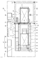
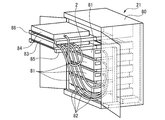
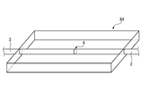
- FIG. 1 is a schematic plan view of a laser beam machine according to an embodiment of the present invention. It is a schematic side view of the laser processing machine shown in FIG. It is a perspective view of a processing head drive mechanism. It is a perspective view of a processing head. It is a rear view of the laser processing machine shown in FIG. It is a perspective view by the side of the right side of the laser beam machine shown in FIG. It is a perspective view by the side of the left side of the laser beam machine shown in FIG. It is a perspective view which shows the state which opened the door of the laser oscillator. It is a figure which shows the inside of a fusion box.
- the fiber connection structure 1 of this embodiment is applied to, for example, a fiber laser processing machine 10 to be described later.
- a feeding fiber cable 2 and a process fiber cable 3 having the same core diameter are provided.
- 2a is the core of the feeding fiber cable
- 2b is the cladding of the feeding fiber cable
- 3a is the core of the process fiber cable
- 3b is the cladding of the process fiber cable 3
- 4 is fused. Shows the part.
- the difference in core diameter between the two fiber cables is ⁇ 10% or less, the two fiber cables are assumed to have the same core diameter.
- the feeding fiber cable 2 and the process fiber cable 3 have the same core diameter. It is assumed that each core diameter is equal.
- the feeding fiber cable 2 and the process fiber cable 3 only have to have the same core diameter in the fused portion 4, but each preferably has a uniform core diameter. Thereby, without performing special processing on the feeding fiber cable 2 and the process fiber cable, it is possible to suppress a decrease in luminance due to a difference in core diameter, and to improve beam quality.
- the distribution of the core diameter of the fiber cable is in the range of ⁇ 10% or less, the fiber cable is assumed to have a uniform core diameter. For example, when the feeding fiber cable 2 (or process fiber cable 3) has a core diameter of 50 ⁇ 5 ⁇ m over its entire length, the feeding fiber cable 2 (or process fiber cable 3) has a uniform core diameter. It shall have.
- the fusing process is performed by arranging the end surfaces of the feeding fiber cable 2 and the process fiber cable 3 so as to face each other and heating in a state where both end surfaces are abutted.
- This fusion process can be performed using an optical fiber fusion splicer, but is preferably performed using a core direct-view optical fiber fusion splicer having excellent alignment performance.
- By performing the fusion process using an optical fiber fusion splicer it becomes possible to use the process fiber cable 3 having a smaller core diameter than before, and by connecting the cables 2 and 3 having a smaller core diameter, The spread angle M of the laser can be reduced, and the cutting speed can be increased.
- the core diameter of the feeding fiber cable 2 and the process fiber cable 3 is preferably about 100 ⁇ m or less, and more preferably about 50 ⁇ m or less.
- the clad diameter is not particularly limited, and the clad diameter may be different between the feeding fiber cable 2 and the process fiber cable 3 or may be the same diameter.
- a fiber laser processing machine 10 (hereinafter referred to as a laser processing machine) includes a processing machine body 20 and a fiber laser oscillator 21 (hereinafter referred to as a laser oscillator) connected to the processing machine body 20. And a control device 22, a pallet changer 23 connected to the processing machine main body 20, a booster compressor 24 and an air compressor 25 used for separating nitrogen gas in the air, or An assist gas supply unit 27 including an oxygen gas cylinder 26, a chiller unit 28 for supplying cooling water for cooling the laser oscillator 21 and a laser processing head 40 (hereinafter referred to as a processing head), dust generated during processing, and the like. Mainly equipped with a dust collector 29 to be excluded.
- the front indicates a direction closer to the processing machine main body 20 in the arrangement direction (X direction in FIG. 2) of the processing machine main body 20 and the pallet changer 23, and the rear indicates the pallet in the arrangement direction. This represents the direction closer to the changer 23. Further, the left side and the right side are represented by directions when the front is viewed from the rear in a direction (Y direction in FIG. 2) orthogonal to the arrangement direction.
- a pallet driving mechanism 32 that drives a pallet 31 in a longitudinal direction (X direction) of the cabin 30, which is a predetermined direction, is formed in a cabin 30 that forms a part of the processing machine body 20 and forms the outer shape of the processing machine body 20.
- a processing head 40 for irradiating a laser beam for processing the workpiece W mounted on the pallet 31, a processing head drive mechanism 49 for driving the processing head 40, and chips and the like cut at the time of processing are collected.
- a collection conveyor 60 is accommodated.
- the processing head 40 is provided in the processing machine body 20, and is processed by the processing head drive mechanism 49 in the X direction, the width direction (Y direction) of the cabin 30, and the vertical direction (Z direction) of the cabin 30. It is movable. Specifically, a pair of support bases 41 provided on the left and right sides are arranged so as to straddle a beam-shaped X-direction movable base 42, and the X-direction movable base 42 is driven in the X direction by an X-axis motor 43. .
- the X-direction movable table 42 is provided with a Y-direction movable table 45 that is driven by a Y-axis motor 44 and can move in the Y direction.
- the Y-direction movable table 45 is driven in the Y direction by a rack and pinion mechanism in which a not-illustrated pinion fixed to the rotation shaft of the Y-axis motor 44 meshes with a rack (not illustrated) arranged in the X-direction movable table 42.
- the machining head 40 is disposed on the Y-direction movable table 45 so as to be movable in the Z direction using a rack and pinion mechanism driven by a Z-axis motor 46.
- the machining head 40 indicated by the solid line in FIG. 2 and the dotted line in FIG. 3 represents the state that is located at the foremost position in the X direction (the installation position when the pallet 31 is processed), and the machining head indicated by the one-dot chain line in FIGS.
- the head 40 represents a state that is located most rearward in the X direction.
- a process fiber cable (only the tip is shown) 3 extending from the laser oscillator 21 is arranged via an X-direction cable bear (registered trademark) 48x and a Y-direction cable bear (registered trademark) 48y. Connected by searching. Further, in the processing head 40, a collimator lens 51 for collimating the laser beam emitted from the exit end of the process fiber cable 3, and a condensing lens for condensing the collimated laser beam. 52, and the condensing lens 52 is provided such that its position can be adjusted in the Z direction with respect to the processing head 40.
- a cooling pipe 56 supplied from the chiller unit 28 is connected around the processing head 40, and the output end of the process fiber cable 3 and the periphery of the condenser lens 52 are cooled. To do. Further, around the processing head 40, a gas supply pipe 57 that supplies an assist gas of nitrogen gas or oxygen gas from the assist gas supply unit 27 to the processing head 40 and the vicinity of the laser nozzle 53 of the processing head 40. In addition, a gas supply pipe 58 connected to the side nozzle 54 for blowing nitrogen gas or oxygen gas assist gas is provided.
- the cooling pipe 56 and the gas supply pipes 57 and 58 pass through the Z-direction cable bear (registered trademark) 48z, and then, together with the process fiber cable 3, the X-direction cable bear (registered trademark) 48x and Y
- the directional cable bear (registered trademark) 48 y is routed and connected to the chiller unit 28 and the assist gas supply unit 27.
- the processing head 40 When the processing head 40 operates the laser oscillator 21, the laser light is collimated by the collimator lens 51 via the process fiber cable 3, and the collimated laser light is incident on the condenser lens 52 and collected.
- the workpiece W is processed by being irradiated from the laser nozzle 53 to the processing portion of the workpiece W.
- the assist gas supplied from the assist gas supply unit 27 is ejected from the laser nozzle 53 and the side nozzle 54 toward the processing unit of the workpiece W, and the molten metal generated during the processing is blown off.
- the pallet driving mechanism 32 is disposed at a position facing the right side surface of the pallet 31 along the X direction, and the pallet 31 is rotated with a drive motor 33.
- a plurality of rollers 36 provided on the lower surface side of the roller are guided to roll and have a rail 35 that supports the pallet 31.
- a pin (not shown) provided on the endless chain 34 engages with an engaging portion (not shown) of the pallet 31, and the pallet on the rail 35. 31 is moved in the X direction.
- the cabin 30 is provided with a gull wing 38 as an open / close door on the front surface 30F, and a loading / unloading port 37 formed in a horizontally long slit shape on the back surface 30B opposite to the front surface 30F. Is provided corresponding to the pallet changer 23.
- the pallet 31 on which the workpiece W is placed is loaded / unloaded via the loading / unloading port 37, and when processing a small lot product, the workpiece W is loaded / unloaded from the gull wing 38 to correspond to the size of the lot. Can be carried out.
- a first operation panel 75 is disposed on the front surface 30F of the cabin 30 on the side of the gull wing 38, and a second operation panel 70 is disposed near the rear surface 30B on the left side surface 30L. Further, a foot switch 76 that can be operated by the operator's foot is disposed below the gull wing 38 on the front surface 30F of the cabin 30.
- a concave oscillator housing portion 30 a that houses the laser oscillator 21 is disposed at a substantially central portion.
- the laser oscillator 21 arranged in the oscillator housing 30a includes a plurality of (four in the present embodiment) fiber laser modules 81 that generate laser light in a box-shaped housing 80.
- a combiner 83 to which an output cable 82 from each fiber laser module 81 is connected is accommodated.
- a fusion box 84 connected to the combiner 83 by the feeding fiber cable 2 is accommodated above the combiner 83.
- the process fiber cable 3 connected to the processing head 40 is introduced into the fusion box 84 on the side opposite to the side where the feeding fiber cable 2 is introduced.
- a fused portion 4 between the fiber cable 2 and the process fiber cable 3 is disposed.
- the combiner 83 and the fusion box 84 are arranged on a combiner table 85 and a fusion table 86 that can be pulled out from the housing 80, respectively.
- the pallet changer 23 is disposed so as to face the back surface 30 ⁇ / b> B of the cabin 30 provided with the loading / unloading port 37.
- the pallet changer 23 has a movable frame 62 that is driven up and down by a drive mechanism 61 shown in FIG. 2, and two pallets are placed on an angular C-shaped rail 63 provided on the left and right sides of the movable frame 62. 31 can be arranged in two stages up and down.
- the upper pallet 31 is placed on the upper rail surface 63a of the squared substantially C-shaped rail 63, and the lower pallet 31 is placed on the lower rail surface 63b of the squared substantially C-shaped rail 63. Placed on top.
- the pallet 31 arranged in two stages on the substantially square C-shaped rail 63 is moved up and down by moving the movable frame 62 by the drive mechanism 61 so that the pallet 31 on the nearly square C-shaped rail 63 is moved up and down.
- the height of the pallet 31 can be adjusted so as to be the same height as that of the rail 35 disposed in the cabin 30, and the pallet 31 located at the same height as the rail 35 is moved to the pallet via the loading / unloading port 37. It can be carried in and out between the changer 23 and the cabin 30.
- a work lifter 66 having a free bearing 64 for moving the work W on the pallet 31 so as to abut on the reference of the pallet 31 is provided to be movable up and down.
- reference numeral 65 denotes a foot switch for operating a drive mechanism 67 that drives the work lifter 66 up and down.
- a sensor composed of a projector 71, a reflector 72, and a light receiver 73 is disposed at each corner of the work area WA surrounding the pallet changer 23, and the light emitted from the projector 71 is By reflecting on the three reflecting plates 72 and receiving the light on the light receiver 73, the entry / exit of the worker or the like into the work area WA is monitored.
- An area sensor 74 is disposed on the back surface 30B of the cabin 30 to detect the presence or absence of an operator or the like in the work area WA.
- the fiber connection structure 1 of the present embodiment can be applied not only to the above-described laser processing machine 10 but also to various fiber laser processing machines.
- a feeding fiber cable 2 and the process fiber cable 3 can be arranged on a fusion table 86 that can be pulled out from the housing 80 of the laser oscillator 21. This facilitates the fusion process between the feeding fiber cable 2 and the process fiber cable 3, and the fusion process usually performed in a clean room such as a factory is performed at the assembly place of the laser processing machine 10 or the laser processing machine 10. It is possible to carry out at the installation location etc.
- the fusion table 86 is pulled out from the housing 80, and the drawn portion is covered with a simple clean booth to form a simple clean room for easy fusion processing. Can do.
- the fusion table 86 and the fusion box 84 may be formed integrally or separately.
- the combiner table 85 does not necessarily need to be pulled out from the housing 80, but can be pulled out in the same manner as the fusion table 86, so that the fiber laser module 81 can be easily replaced and expanded. Is possible.
- the laser oscillator 21 can be stored in the oscillator storage portion 30 a formed on the right side surface 30 ⁇ / b> R of the cabin 30, so that the laser oscillator is installed away from the processing machine body 20. Compared to this, the unit is well organized and can be accommodated in the cabin 30 of the processing machine body 20, so that the entire laser processing machine 10 can be downsized. Further, the laser oscillator 21 and the fiber laser processing machine main body 20 can be transported together in a state where the feeding fiber cable 2 and the process fiber cable 3 are fused.
- a fiber laser processing machine (Example 1) with an output of 1 kW employing the fiber connection structure of the present invention (Example 1) and a fiber laser processing machine with an output of 2 kW of the present invention (Example 2)
- a conventional 2 kW fiber laser processing machine (Comparative Example 1)
- a conventional 4 kW fiber laser processing machine (Comparative Example 2)
- a 2 kW carbon dioxide laser processing machine (Comparative Example 3)
- dross is generated. It measured about the cutting speed (henceforth an upper limit cutting speed) of the range (what is called dross-free cutting) which does not.
- FIG. 11 is a graph summarizing the upper limit cutting speed with respect to the plate thickness in each fiber laser processing machine
- FIG. 12A is a graph showing the upper limit cutting speed of each fiber laser processing machine when the plate thickness is 1 mm.
- FIG. 12 (b) is a graph showing the upper limit cutting speed of each fiber laser beam machine when the plate thickness is 2 mm.
- the fiber laser processing machine of Example 1 has a double output, the fiber laser processing machine of Comparative Example 1 and the carbonic acid of Comparative Example 3
- the upper cutting speed was almost the same as the gas laser processing machine.
- the fiber laser processing machine of Example 2 shows an upper limit cutting speed that is three times or more that of the fiber laser processing machine of Comparative Example 1 and the carbon dioxide gas laser processing machine of Comparative Example 3 having the same output, and further doubles the output.
- the upper limit cutting speed was almost the same as that of the fiber laser processing machine of Comparative Example 2 having.
- the fiber laser processing machine of Example 1 has an output that is twice as high as the fiber laser processing machine of Comparative Example 1, which is the same as the upper limit cutting.
- the upper limit cutting speed was about 3 times that of the carbon dioxide laser processing machine of Comparative Example 3.
- the fiber laser processing machine of Example 2 has the same output, and exhibits an upper limit cutting speed that is twice or more that of the fiber laser processing machine of Comparative Example 1 and 6 times or more that of the carbon dioxide laser processing machine of Comparative Example 3, The upper cutting speed was higher than that of the fiber laser processing machine of Comparative Example 2 having a double output.
- the upper limit is remarkably higher than that of the laser processing machine and the carbon dioxide laser processing machine having the same output particularly when cutting a thin plate material of 2 mm or less.
- the cutting speed was shown, and the upper cutting speed was almost the same as that of a laser processing machine having a double output. This means that the same cutting operation can be performed in a short time due to the difference in the upper limit cutting speed for laser processing machines having the same output, and the same cutting is performed for laser processing machines having twice the output. This means that work can be performed with low power consumption.
- the process fiber cable 3 having a core diameter equal to the core diameter of the feeding fiber cable 2 is obtained by connecting the feeding fiber cable 2 and the process fiber cable 3 by fusion. It can be used, a decrease in luminance due to a difference in core diameter can be suppressed, and beam quality can be improved. Further, the core diameter of the process fiber cable 3 can be made smaller than that of the conventional one by fusion, the laser divergence angle, also called a beam mode, can be reduced, and the cutting speed can be increased.
- the configuration in the housing 80 of the laser oscillator 21 is not limited to the above embodiment, and a plurality of fiber laser modules 81 may be arranged side by side. Further, it is sufficient that at least one fiber laser module 81 is accommodated, the number thereof can be changed as appropriate, and a module installation space may be secured so that it can be added later.
Landscapes
- Physics & Mathematics (AREA)
- Engineering & Computer Science (AREA)
- Optics & Photonics (AREA)
- Mechanical Engineering (AREA)
- Plasma & Fusion (AREA)
- General Physics & Mathematics (AREA)
- Robotics (AREA)
- Laser Beam Processing (AREA)
- Mechanical Coupling Of Light Guides (AREA)
- Lasers (AREA)
Abstract
Description
(a)カップリングユニットにおいては、フィーディングファイバケーブルからプロセスファイバケーブルにレーザ光を伝送するためにコリメータレンズ、フォーカシングレンズを用いることから、レンズによるレーザ光の収差があり、出力が低減する。
(b)プロセスファイバケーブルのコア径がフィーディングファイバケーブルのコア径よりも大きいため、レーザ光を伝送する際にレーザ光の輝度が低減する。
(c)カップリングユニットがファイバレーザ発振器の大きさに影響し、ファイバレーザ発振器を小型化することが難しい。
(d)コリメータレンズやフォーカシングレンズを介してレーザ光を伝送するため、その調整が難しい。
ただし、Pは出力、dはスポット系(焦点径)であり、パワー密度PDは単位面積あたりのパワーを示すものである。
=(β×M×λ×fL)/fC (b)
ただし、α、βは係数、Mはレーザ広がり角(ビームモード)、λはレーザの波長、fLは集光レンズの焦点距離、fCはコリメータの焦点距離である。
(1) レーザ光を照射するレーザ加工ヘッドを設けた加工機本体と、
レーザ光を生成するファイバレーザモジュール及び該ファイバレーザモジュールが生成したレーザ光をまとめて取り出すフィーディングファイバケーブルを有するファイバレーザ発振器と、
該ファイバレーザ発振器のフィーディングファイバケーブルによって取り出されるレーザ光を前記加工機本体のレーザ加工ヘッドに伝送するプロセスファイバケーブルと、を備えたファイバレーザ加工機であって、
前記フィーディングファイバケーブルと前記プロセスファイバケーブルとは融着により接合され、
前記フィーディングファイバケーブルと前記プロセスファイバケーブルのコア径が等しいことを特徴とするファイバレーザ加工機。
(2) 前記フィーディングファイバケーブルと前記プロセスファイバケーブルは、それぞれ一様のコア径を有することを特徴とする(1)に記載のファイバレーザ加工機。
(3) 前記ファイバレーザ発振器は、前記ファイバレーザモジュールと前記フィーディングファイバケーブルを収容する筐体を備え、
前記フィーディングファイバケーブルと前記プロセスファイバケーブルとの融着部は、前記筐体内に収容される引き出し可能な融着テーブル上に配置されることを特徴とする(1)又は(2)に記載のファイバレーザ加工機。
(4) 前記加工機本体は、前記レーザ加工ヘッドを収容し前記加工機本体の外形を形成するキャビンを備え、
前記キャビンは、側面に前記ファイバレーザ発振器を収容する発振器収容部を有し、該発振器収容部に前記ファイバレーザ発振器が前記筐体の状態で収容されることを特徴とする(3)に記載のファイバレーザ加工機。
(5) レーザ光を生成するファイバレーザモジュール及び該ファイバレーザモジュールが生成したレーザ光をまとめて取り出すフィーディングファイバケーブルを有するファイバレーザ発振器と、前記フィーディングファイバケーブルによって取り出されるレーザ光をレーザ加工ヘッドに伝送するプロセスファイバケーブルとを備えたファイバレーザ加工機に用いられ、前記フィーディングファイバケーブルと前記プロセスファイバケーブルとを接続するファイバ接続方法であって、
前記ファイバレーザ発振器の筐体内に設けられた引き出し可能な融着テーブル上で、融着することを特徴とするファイバ接続方法。
(6) レーザ光を生成するファイバレーザモジュールと、
該ファイバレーザモジュールが生成したレーザ光をまとめて取り出すフィーディングファイバケーブルと、
前記ファイバレーザモジュールと前記フィーディングファイバケーブルを収容する筐体と、を備え、
レーザ加工ヘッドにレーザ光を伝送するプロセスファイバケーブルに接続されるファイバレーザ発振器であって、
前記フィーディングファイバケーブルと前記プロセスファイバケーブルとは融着により接合され、
前記フィーディングファイバケーブルと前記プロセスファイバケーブルとの融着部は、前記筐体内に、引き出し可能に収容される融着テーブル上に配置されることを特徴とするファイバレーザ発振器。
本実施形態のファイバ接続構造1は、例えば後述するファイバレーザ加工機10に適用されるものであり、図1に示すように、同一のコア径を有するフィーディングファイバケーブル2とプロセスファイバケーブル3とが融着により接続されている。図1中、2aはフィーディングファイバケーブル2のコア、2bはフィーディングファイバケーブル2のクラッドを示し、3aはプロセスファイバケーブル3のコア、3bはプロセスファイバケーブル3のクラッドを示し、4は融着部を示している。なお本明細書においては、2本のファイバケーブルの各々のコア径の差が±10%以下であれば、当該2本のファイバケーブルは同一のコア径を有しているものとする。たとえば、フィーディングファイバケーブル2のコア径が50μmである場合、プロセスファイバケーブル3のコア径が50±5μmの範囲にあれば、フィーディングファイバケーブル2とプロセスファイバケーブル3とは同一のコア径を有しており、各々のコア径が等しいものとする。
本発明のファイバ接続構造の効果を実証するため、本発明のファイバ接続構造を採用した出力1kWのファイバレーザ加工機(実施例1)、本発明の出力2kWのファイバレーザ加工機(実施例2)、従来の出力2kWのファイバレーザ加工機(比較例1)、従来の出力4kWのファイバレーザ加工機(比較例2)、出力2kWの炭酸ガスレーザ加工機(比較例3)を用いて、ドロスが発生しない範囲(いわゆる、ドロスフリー切断)の切断速度(以下、上限切断速度と呼ぶ。)について測定した。測定には、SUS304製の3種類の板厚(t=1mm、2mm、3mm)の薄板を用いて、直線状に切断を行った。
2 フィーディングファイバケーブル
3 プロセスファイバケーブル
4 融着部
10 ファイバレーザ加工機
20 加工機本体
21 ファイバレーザ発振器
30 キャビン
30a 発振器収容部
40 レーザ加工ヘッド
80 筐体
81 ファイバレーザモジュール
86 融着テーブル
Claims (6)
- レーザ光を照射するレーザ加工ヘッドを設けた加工機本体と、
レーザ光を生成するファイバレーザモジュール及び該ファイバレーザモジュールが生成したレーザ光をまとめて取り出すフィーディングファイバケーブルを有するファイバレーザ発振器と、
該ファイバレーザ発振器のフィーディングファイバケーブルによって取り出されるレーザ光を前記加工機本体のレーザ加工ヘッドに伝送するプロセスファイバケーブルと、を備えたファイバレーザ加工機であって、
前記フィーディングファイバケーブルと前記プロセスファイバケーブルとは融着により接合され、
前記フィーディングファイバケーブルと前記プロセスファイバケーブルのコア径が等しいことを特徴とするファイバレーザ加工機。 - 前記フィーディングファイバケーブルと前記プロセスファイバケーブルは、それぞれ一様のコア径を有することを特徴とする請求項1に記載のファイバレーザ加工機。
- 前記ファイバレーザ発振器は、前記ファイバレーザモジュールと前記フィーディングファイバケーブルを収容する筐体を備え、
前記フィーディングファイバケーブルと前記プロセスファイバケーブルとの融着部は、前記筐体内に収容される引き出し可能な融着テーブル上に配置されることを特徴とする請求項1又は2に記載のファイバレーザ加工機。 - 前記加工機本体は、前記レーザ加工ヘッドを収容し前記加工機本体の外形を形成するキャビンを備え、
前記キャビンは、側面に前記ファイバレーザ発振器を収容する発振器収容部を有し、該発振器収容部に前記ファイバレーザ発振器が前記筐体の状態で収容されることを特徴とする請求項3に記載のファイバレーザ加工機。 - レーザ光を生成するファイバレーザモジュール及び該ファイバレーザモジュールが生成したレーザ光をまとめて取り出すフィーディングファイバケーブルを有するファイバレーザ発振器と、前記フィーディングファイバケーブルによって取り出されるレーザ光をレーザ加工ヘッドに伝送するプロセスファイバケーブルとを備えたファイバレーザ加工機に用いられ、前記フィーディングファイバケーブルと前記プロセスファイバケーブルとを接続するファイバ接続方法であって、
前記ファイバレーザ発振器の筐体内に設けられた引き出し可能な融着テーブル上で、融着することを特徴とするファイバ接続方法。 - レーザ光を生成するファイバレーザモジュールと、
該ファイバレーザモジュールが生成したレーザ光をまとめて取り出すフィーディングファイバケーブルと、
前記ファイバレーザモジュールと前記フィーディングファイバケーブルを収容する筐体と、を備え、
レーザ加工ヘッドにレーザ光を伝送するプロセスファイバケーブルに接続されるファイバレーザ発振器であって、
前記フィーディングファイバケーブルと前記プロセスファイバケーブルとは融着により接合され、
前記フィーディングファイバケーブルと前記プロセスファイバケーブルとの融着部は、前記筐体内に、引き出し可能に収容される融着テーブル上に配置されることを特徴とするファイバレーザ発振器。
Priority Applications (3)
| Application Number | Priority Date | Filing Date | Title |
|---|---|---|---|
| KR1020157010797A KR20150060926A (ko) | 2012-10-26 | 2013-10-24 | 파이버 레이저 가공기, 파이버 접속 방법 및 파이버 레이저 발진기 |
| US14/434,423 US20150266134A1 (en) | 2012-10-26 | 2013-10-24 | Fiber laser processing machine, fiber connection method and fiber laser oscillator |
| JP2014543340A JP6251684B2 (ja) | 2012-10-26 | 2013-10-24 | ファイバレーザ加工機、ファイバ接続方法及びファイバレーザ発振器 |
Applications Claiming Priority (2)
| Application Number | Priority Date | Filing Date | Title |
|---|---|---|---|
| JP2012-237300 | 2012-10-26 | ||
| JP2012237300 | 2012-10-26 |
Publications (1)
| Publication Number | Publication Date |
|---|---|
| WO2014065360A1 true WO2014065360A1 (ja) | 2014-05-01 |
Family
ID=50544733
Family Applications (1)
| Application Number | Title | Priority Date | Filing Date |
|---|---|---|---|
| PCT/JP2013/078802 Ceased WO2014065360A1 (ja) | 2012-10-26 | 2013-10-24 | ファイバレーザ加工機、ファイバ接続方法及びファイバレーザ発振器 |
Country Status (4)
| Country | Link |
|---|---|
| US (1) | US20150266134A1 (ja) |
| JP (1) | JP6251684B2 (ja) |
| KR (1) | KR20150060926A (ja) |
| WO (1) | WO2014065360A1 (ja) |
Cited By (4)
| Publication number | Priority date | Publication date | Assignee | Title |
|---|---|---|---|---|
| JP5879425B1 (ja) * | 2014-12-12 | 2016-03-08 | 株式会社フジクラ | ファイバレーザ装置および光ファイバ接続装置 |
| JP2017042805A (ja) * | 2015-08-28 | 2017-03-02 | 株式会社ディスコ | レーザー加工装置 |
| DE102017206075A1 (de) | 2016-04-15 | 2017-10-19 | Fanuc Corporation | Faserlaseroszillator und eine in diesem aufnehmbare reinraumbank |
| WO2019198215A1 (ja) * | 2018-04-12 | 2019-10-17 | 三菱電機株式会社 | レーザ装置およびレーザ加工装置 |
Families Citing this family (2)
| Publication number | Priority date | Publication date | Assignee | Title |
|---|---|---|---|---|
| US11517978B2 (en) * | 2012-10-19 | 2022-12-06 | Trumpf Werkzeugmaschinen Gmbh + Co. Kg | Laser cutting machine and method for cutting workpieces of different thicknesses |
| TR201700931A2 (tr) * | 2017-01-20 | 2018-07-23 | Ermaksan Makina Sanayi Ve Ticaret Anonim Sirketi | Fiber Lazer Sistemlerinde Geri Yansıyan Işının Ölçülmesini Ve Sistemin Korunmasını Sağlayan Fiber Çoğaltıcı İzolatör Uygulaması |
Citations (9)
| Publication number | Priority date | Publication date | Assignee | Title |
|---|---|---|---|---|
| JPH06190581A (ja) * | 1992-12-24 | 1994-07-12 | Amada Co Ltd | レーザ加工装置 |
| JPH08206870A (ja) * | 1995-02-08 | 1996-08-13 | Amada Co Ltd | レーザ加工機のカバー装置 |
| JPH10156568A (ja) * | 1996-11-29 | 1998-06-16 | Hitachi Telecom Technol Ltd | シート用レーザ切断装置及びそのレーザ切断加工方法 |
| JP2006192454A (ja) * | 2005-01-12 | 2006-07-27 | Amada Co Ltd | レーザ加工機用キャビン及びキャビン内のレーザ加工機への材料搬出入方法 |
| JP2006227041A (ja) * | 2005-02-15 | 2006-08-31 | Osaki Electric Co Ltd | 光ファイバ収納トレイの引出位置ロック構造、光ファイバ収納ユニット、および光配線盤 |
| JP2009115962A (ja) * | 2007-11-05 | 2009-05-28 | Hata Kensaku:Kk | 光コネクタ接続キット |
| JP2010167433A (ja) * | 2009-01-21 | 2010-08-05 | Omron Corp | レーザ照射装置およびレーザ加工装置 |
| WO2012053045A1 (ja) * | 2010-10-18 | 2012-04-26 | 新日本製鐵株式会社 | レーザ装置及びこれを備えたレーザ加工装置 |
| WO2012108503A1 (ja) * | 2011-02-09 | 2012-08-16 | 住友電気工業株式会社 | レーザ加工方法 |
Family Cites Families (11)
| Publication number | Priority date | Publication date | Assignee | Title |
|---|---|---|---|---|
| US5093887A (en) * | 1990-09-28 | 1992-03-03 | Reliance Comm/Tec Corporation | Sliding cable tray with cable pivot arm |
| US6960035B2 (en) * | 2002-04-10 | 2005-11-01 | Fuji Photo Film Co., Ltd. | Laser apparatus, exposure head, exposure apparatus, and optical fiber connection method |
| JP4357944B2 (ja) * | 2003-12-05 | 2009-11-04 | トヨタ自動車株式会社 | 固体レーザ加工装置およびレーザ溶接方法 |
| DK1788414T3 (da) * | 2004-06-22 | 2017-01-02 | Fujikura Ltd | Forbindelsesfremgangsmåde og struktur af fotonisk krystalfiber |
| JP5048978B2 (ja) * | 2006-07-14 | 2012-10-17 | 株式会社ディスコ | レーザ加工装置 |
| JP2010078704A (ja) * | 2008-09-24 | 2010-04-08 | Mitsubishi Cable Ind Ltd | 光ファイバの接続構造 |
| DE102008062847A1 (de) * | 2008-12-23 | 2010-06-24 | Jt Optical Engine Gmbh + Co. Kg | Spleißverbindung zwischen zwei optischen Fasern sowie Verfahren zum Herstellen einer solchen Spleißverbindung |
| JP5434703B2 (ja) * | 2010-03-11 | 2014-03-05 | オムロン株式会社 | 光ファイバ接続構造、レーザ照射装置およびレーザ加工装置 |
| US8710398B2 (en) * | 2010-05-19 | 2014-04-29 | Joining Technologies, Inc. | Method and apparatus for laser strip splicing |
| JP2012027241A (ja) * | 2010-07-23 | 2012-02-09 | Amada Co Ltd | ファイバレーザ加工機に用いられるファイバ接続方法及びファイバ接続構造 |
| WO2012165389A1 (ja) * | 2011-05-31 | 2012-12-06 | 古河電気工業株式会社 | レーザ装置および加工装置 |
-
2013
- 2013-10-24 US US14/434,423 patent/US20150266134A1/en not_active Abandoned
- 2013-10-24 KR KR1020157010797A patent/KR20150060926A/ko not_active Ceased
- 2013-10-24 JP JP2014543340A patent/JP6251684B2/ja active Active
- 2013-10-24 WO PCT/JP2013/078802 patent/WO2014065360A1/ja not_active Ceased
Patent Citations (9)
| Publication number | Priority date | Publication date | Assignee | Title |
|---|---|---|---|---|
| JPH06190581A (ja) * | 1992-12-24 | 1994-07-12 | Amada Co Ltd | レーザ加工装置 |
| JPH08206870A (ja) * | 1995-02-08 | 1996-08-13 | Amada Co Ltd | レーザ加工機のカバー装置 |
| JPH10156568A (ja) * | 1996-11-29 | 1998-06-16 | Hitachi Telecom Technol Ltd | シート用レーザ切断装置及びそのレーザ切断加工方法 |
| JP2006192454A (ja) * | 2005-01-12 | 2006-07-27 | Amada Co Ltd | レーザ加工機用キャビン及びキャビン内のレーザ加工機への材料搬出入方法 |
| JP2006227041A (ja) * | 2005-02-15 | 2006-08-31 | Osaki Electric Co Ltd | 光ファイバ収納トレイの引出位置ロック構造、光ファイバ収納ユニット、および光配線盤 |
| JP2009115962A (ja) * | 2007-11-05 | 2009-05-28 | Hata Kensaku:Kk | 光コネクタ接続キット |
| JP2010167433A (ja) * | 2009-01-21 | 2010-08-05 | Omron Corp | レーザ照射装置およびレーザ加工装置 |
| WO2012053045A1 (ja) * | 2010-10-18 | 2012-04-26 | 新日本製鐵株式会社 | レーザ装置及びこれを備えたレーザ加工装置 |
| WO2012108503A1 (ja) * | 2011-02-09 | 2012-08-16 | 住友電気工業株式会社 | レーザ加工方法 |
Cited By (9)
| Publication number | Priority date | Publication date | Assignee | Title |
|---|---|---|---|---|
| JP5879425B1 (ja) * | 2014-12-12 | 2016-03-08 | 株式会社フジクラ | ファイバレーザ装置および光ファイバ接続装置 |
| JP2017042805A (ja) * | 2015-08-28 | 2017-03-02 | 株式会社ディスコ | レーザー加工装置 |
| DE102017206075A1 (de) | 2016-04-15 | 2017-10-19 | Fanuc Corporation | Faserlaseroszillator und eine in diesem aufnehmbare reinraumbank |
| JP2017191907A (ja) * | 2016-04-15 | 2017-10-19 | ファナック株式会社 | ファイバレーザ発振器及びこれに搭載可能なクリーンベンチ |
| CN107302173A (zh) * | 2016-04-15 | 2017-10-27 | 发那科株式会社 | 光纤激光振荡器以及在光纤激光振荡器可装载的净化台 |
| US10027082B2 (en) | 2016-04-15 | 2018-07-17 | Fanuc Corporation | Fiber laser oscillator and clean bench mountable to the same |
| DE102017206075B4 (de) | 2016-04-15 | 2019-12-24 | Fanuc Corporation | Faserlaseroszillator |
| WO2019198215A1 (ja) * | 2018-04-12 | 2019-10-17 | 三菱電機株式会社 | レーザ装置およびレーザ加工装置 |
| JPWO2019198215A1 (ja) * | 2018-04-12 | 2020-04-30 | 三菱電機株式会社 | レーザ装置およびレーザ加工装置 |
Also Published As
| Publication number | Publication date |
|---|---|
| KR20150060926A (ko) | 2015-06-03 |
| JP6251684B2 (ja) | 2017-12-20 |
| JPWO2014065360A1 (ja) | 2016-09-08 |
| US20150266134A1 (en) | 2015-09-24 |
Similar Documents
| Publication | Publication Date | Title |
|---|---|---|
| JP6251684B2 (ja) | ファイバレーザ加工機、ファイバ接続方法及びファイバレーザ発振器 | |
| JP5816370B2 (ja) | ファイバレーザ加工機の出力制御方法及びファイバレーザ加工機 | |
| EP3431219B1 (en) | Fiber coupling device | |
| JP5731983B2 (ja) | 脆性ワークの切断方法及び切断装置 | |
| US20100252543A1 (en) | Laser-scribing tool architecture | |
| JP5876931B2 (ja) | 熱切断機 | |
| US20210252637A1 (en) | Laser-jet liquid beam self-generated abrasive particle flow composite processing device and method | |
| CN112935579A (zh) | 一种激光切膜设备 | |
| JP2014083592A (ja) | レーザ加工機及びレーザ加工機の冷却方法 | |
| JP6027852B2 (ja) | レーザ加工機用加工ヘッド | |
| JPH10314973A (ja) | 複合レーザビームによるレーザ加工装置および加工法 | |
| CN118616881A (zh) | 一种具有自动调节效果的激光切割设备 | |
| CN111958104B (zh) | 激光切割和雕刻标记一体机 | |
| CN219966775U (zh) | 一种激光雕刻机 | |
| US20120132628A1 (en) | Orthogonal integrated cleaving device | |
| JP7703366B2 (ja) | レーザ加工装置およびレーザ加工方法 | |
| CN204397164U (zh) | 一种大功率焊接头 | |
| WO2003061895A1 (en) | Means for visualizing the laser beam in a laser machining system | |
| CN109834389A (zh) | 一种用于连续轧制的多功能焊接设备及焊接方法 | |
| KR100800565B1 (ko) | 고속 파이버레이저 가공장치 | |
| JP2014083589A (ja) | 熱加工機 | |
| CN221516487U (zh) | 激光加工机床及其二氧化碳激光加工头 | |
| JP2014083593A (ja) | 熱切断機 | |
| CN115488496B (zh) | 多轴联动激光加工机床 | |
| CN220240361U (zh) | 一种激光切割设备 |
Legal Events
| Date | Code | Title | Description |
|---|---|---|---|
| 121 | Ep: the epo has been informed by wipo that ep was designated in this application |
Ref document number: 13848951 Country of ref document: EP Kind code of ref document: A1 |
|
| ENP | Entry into the national phase |
Ref document number: 2014543340 Country of ref document: JP Kind code of ref document: A |
|
| WWE | Wipo information: entry into national phase |
Ref document number: 14434423 Country of ref document: US |
|
| ENP | Entry into the national phase |
Ref document number: 20157010797 Country of ref document: KR Kind code of ref document: A |
|
| NENP | Non-entry into the national phase |
Ref country code: DE |
|
| 122 | Ep: pct application non-entry in european phase |
Ref document number: 13848951 Country of ref document: EP Kind code of ref document: A1 |