WO2014065237A1 - 車両用制動制御装置 - Google Patents
車両用制動制御装置 Download PDFInfo
- Publication number
- WO2014065237A1 WO2014065237A1 PCT/JP2013/078476 JP2013078476W WO2014065237A1 WO 2014065237 A1 WO2014065237 A1 WO 2014065237A1 JP 2013078476 W JP2013078476 W JP 2013078476W WO 2014065237 A1 WO2014065237 A1 WO 2014065237A1
- Authority
- WO
- WIPO (PCT)
- Prior art keywords
- braking force
- cylinder
- brake
- wheel
- speed
- Prior art date
- Legal status (The legal status is an assumption and is not a legal conclusion. Google has not performed a legal analysis and makes no representation as to the accuracy of the status listed.)
- Ceased
Links
Images



Classifications
-
- B—PERFORMING OPERATIONS; TRANSPORTING
- B60—VEHICLES IN GENERAL
- B60T—VEHICLE BRAKE CONTROL SYSTEMS OR PARTS THEREOF; BRAKE CONTROL SYSTEMS OR PARTS THEREOF, IN GENERAL; ARRANGEMENT OF BRAKING ELEMENTS ON VEHICLES IN GENERAL; PORTABLE DEVICES FOR PREVENTING UNWANTED MOVEMENT OF VEHICLES; VEHICLE MODIFICATIONS TO FACILITATE COOLING OF BRAKES
- B60T11/00—Transmitting braking action from initiating means to ultimate brake actuator without power assistance or drive or where such assistance or drive is irrelevant
- B60T11/10—Transmitting braking action from initiating means to ultimate brake actuator without power assistance or drive or where such assistance or drive is irrelevant transmitting by fluid means, e.g. hydraulic
- B60T11/16—Master control, e.g. master cylinders
-
- B—PERFORMING OPERATIONS; TRANSPORTING
- B60—VEHICLES IN GENERAL
- B60L—PROPULSION OF ELECTRICALLY-PROPELLED VEHICLES; SUPPLYING ELECTRIC POWER FOR AUXILIARY EQUIPMENT OF ELECTRICALLY-PROPELLED VEHICLES; ELECTRODYNAMIC BRAKE SYSTEMS FOR VEHICLES IN GENERAL; MAGNETIC SUSPENSION OR LEVITATION FOR VEHICLES; MONITORING OPERATING VARIABLES OF ELECTRICALLY-PROPELLED VEHICLES; ELECTRIC SAFETY DEVICES FOR ELECTRICALLY-PROPELLED VEHICLES
- B60L7/00—Electrodynamic brake systems for vehicles in general
- B60L7/10—Dynamic electric regenerative braking
- B60L7/18—Controlling the braking effect
-
- B—PERFORMING OPERATIONS; TRANSPORTING
- B60—VEHICLES IN GENERAL
- B60T—VEHICLE BRAKE CONTROL SYSTEMS OR PARTS THEREOF; BRAKE CONTROL SYSTEMS OR PARTS THEREOF, IN GENERAL; ARRANGEMENT OF BRAKING ELEMENTS ON VEHICLES IN GENERAL; PORTABLE DEVICES FOR PREVENTING UNWANTED MOVEMENT OF VEHICLES; VEHICLE MODIFICATIONS TO FACILITATE COOLING OF BRAKES
- B60T1/00—Arrangements of braking elements, i.e. of those parts where braking effect occurs specially for vehicles
- B60T1/02—Arrangements of braking elements, i.e. of those parts where braking effect occurs specially for vehicles acting by retarding wheels
- B60T1/10—Arrangements of braking elements, i.e. of those parts where braking effect occurs specially for vehicles acting by retarding wheels by utilising wheel movement for accumulating energy, e.g. driving air compressors
-
- B—PERFORMING OPERATIONS; TRANSPORTING
- B60—VEHICLES IN GENERAL
- B60T—VEHICLE BRAKE CONTROL SYSTEMS OR PARTS THEREOF; BRAKE CONTROL SYSTEMS OR PARTS THEREOF, IN GENERAL; ARRANGEMENT OF BRAKING ELEMENTS ON VEHICLES IN GENERAL; PORTABLE DEVICES FOR PREVENTING UNWANTED MOVEMENT OF VEHICLES; VEHICLE MODIFICATIONS TO FACILITATE COOLING OF BRAKES
- B60T13/00—Transmitting braking action from initiating means to ultimate brake actuator with power assistance or drive; Brake systems incorporating such transmitting means, e.g. air-pressure brake systems
- B60T13/10—Transmitting braking action from initiating means to ultimate brake actuator with power assistance or drive; Brake systems incorporating such transmitting means, e.g. air-pressure brake systems with fluid assistance, drive, or release
- B60T13/12—Transmitting braking action from initiating means to ultimate brake actuator with power assistance or drive; Brake systems incorporating such transmitting means, e.g. air-pressure brake systems with fluid assistance, drive, or release the fluid being liquid
- B60T13/14—Transmitting braking action from initiating means to ultimate brake actuator with power assistance or drive; Brake systems incorporating such transmitting means, e.g. air-pressure brake systems with fluid assistance, drive, or release the fluid being liquid using accumulators or reservoirs fed by pumps
- B60T13/142—Systems with master cylinder
- B60T13/145—Master cylinder integrated or hydraulically coupled with booster
- B60T13/146—Part of the system directly actuated by booster pressure
-
- B—PERFORMING OPERATIONS; TRANSPORTING
- B60—VEHICLES IN GENERAL
- B60T—VEHICLE BRAKE CONTROL SYSTEMS OR PARTS THEREOF; BRAKE CONTROL SYSTEMS OR PARTS THEREOF, IN GENERAL; ARRANGEMENT OF BRAKING ELEMENTS ON VEHICLES IN GENERAL; PORTABLE DEVICES FOR PREVENTING UNWANTED MOVEMENT OF VEHICLES; VEHICLE MODIFICATIONS TO FACILITATE COOLING OF BRAKES
- B60T13/00—Transmitting braking action from initiating means to ultimate brake actuator with power assistance or drive; Brake systems incorporating such transmitting means, e.g. air-pressure brake systems
- B60T13/10—Transmitting braking action from initiating means to ultimate brake actuator with power assistance or drive; Brake systems incorporating such transmitting means, e.g. air-pressure brake systems with fluid assistance, drive, or release
- B60T13/12—Transmitting braking action from initiating means to ultimate brake actuator with power assistance or drive; Brake systems incorporating such transmitting means, e.g. air-pressure brake systems with fluid assistance, drive, or release the fluid being liquid
- B60T13/14—Transmitting braking action from initiating means to ultimate brake actuator with power assistance or drive; Brake systems incorporating such transmitting means, e.g. air-pressure brake systems with fluid assistance, drive, or release the fluid being liquid using accumulators or reservoirs fed by pumps
- B60T13/142—Systems with master cylinder
- B60T13/147—In combination with distributor valve
-
- B—PERFORMING OPERATIONS; TRANSPORTING
- B60—VEHICLES IN GENERAL
- B60T—VEHICLE BRAKE CONTROL SYSTEMS OR PARTS THEREOF; BRAKE CONTROL SYSTEMS OR PARTS THEREOF, IN GENERAL; ARRANGEMENT OF BRAKING ELEMENTS ON VEHICLES IN GENERAL; PORTABLE DEVICES FOR PREVENTING UNWANTED MOVEMENT OF VEHICLES; VEHICLE MODIFICATIONS TO FACILITATE COOLING OF BRAKES
- B60T13/00—Transmitting braking action from initiating means to ultimate brake actuator with power assistance or drive; Brake systems incorporating such transmitting means, e.g. air-pressure brake systems
- B60T13/10—Transmitting braking action from initiating means to ultimate brake actuator with power assistance or drive; Brake systems incorporating such transmitting means, e.g. air-pressure brake systems with fluid assistance, drive, or release
- B60T13/66—Electrical control in fluid-pressure brake systems
- B60T13/662—Electrical control in fluid-pressure brake systems characterised by specified functions of the control system components
-
- B—PERFORMING OPERATIONS; TRANSPORTING
- B60—VEHICLES IN GENERAL
- B60T—VEHICLE BRAKE CONTROL SYSTEMS OR PARTS THEREOF; BRAKE CONTROL SYSTEMS OR PARTS THEREOF, IN GENERAL; ARRANGEMENT OF BRAKING ELEMENTS ON VEHICLES IN GENERAL; PORTABLE DEVICES FOR PREVENTING UNWANTED MOVEMENT OF VEHICLES; VEHICLE MODIFICATIONS TO FACILITATE COOLING OF BRAKES
- B60T13/00—Transmitting braking action from initiating means to ultimate brake actuator with power assistance or drive; Brake systems incorporating such transmitting means, e.g. air-pressure brake systems
- B60T13/10—Transmitting braking action from initiating means to ultimate brake actuator with power assistance or drive; Brake systems incorporating such transmitting means, e.g. air-pressure brake systems with fluid assistance, drive, or release
- B60T13/66—Electrical control in fluid-pressure brake systems
- B60T13/68—Electrical control in fluid-pressure brake systems by electrically-controlled valves
- B60T13/686—Electrical control in fluid-pressure brake systems by electrically-controlled valves in hydraulic systems or parts thereof
-
- B—PERFORMING OPERATIONS; TRANSPORTING
- B60—VEHICLES IN GENERAL
- B60T—VEHICLE BRAKE CONTROL SYSTEMS OR PARTS THEREOF; BRAKE CONTROL SYSTEMS OR PARTS THEREOF, IN GENERAL; ARRANGEMENT OF BRAKING ELEMENTS ON VEHICLES IN GENERAL; PORTABLE DEVICES FOR PREVENTING UNWANTED MOVEMENT OF VEHICLES; VEHICLE MODIFICATIONS TO FACILITATE COOLING OF BRAKES
- B60T7/00—Brake-action initiating means
- B60T7/02—Brake-action initiating means for personal initiation
- B60T7/04—Brake-action initiating means for personal initiation foot actuated
- B60T7/042—Brake-action initiating means for personal initiation foot actuated by electrical means, e.g. using travel or force sensors
-
- B—PERFORMING OPERATIONS; TRANSPORTING
- B60—VEHICLES IN GENERAL
- B60T—VEHICLE BRAKE CONTROL SYSTEMS OR PARTS THEREOF; BRAKE CONTROL SYSTEMS OR PARTS THEREOF, IN GENERAL; ARRANGEMENT OF BRAKING ELEMENTS ON VEHICLES IN GENERAL; PORTABLE DEVICES FOR PREVENTING UNWANTED MOVEMENT OF VEHICLES; VEHICLE MODIFICATIONS TO FACILITATE COOLING OF BRAKES
- B60T8/00—Arrangements for adjusting wheel-braking force to meet varying vehicular or ground-surface conditions, e.g. limiting or varying distribution of braking force
- B60T8/17—Using electrical or electronic regulation means to control braking
- B60T8/172—Determining control parameters used in the regulation, e.g. by calculations involving measured or detected parameters
-
- B—PERFORMING OPERATIONS; TRANSPORTING
- B60—VEHICLES IN GENERAL
- B60T—VEHICLE BRAKE CONTROL SYSTEMS OR PARTS THEREOF; BRAKE CONTROL SYSTEMS OR PARTS THEREOF, IN GENERAL; ARRANGEMENT OF BRAKING ELEMENTS ON VEHICLES IN GENERAL; PORTABLE DEVICES FOR PREVENTING UNWANTED MOVEMENT OF VEHICLES; VEHICLE MODIFICATIONS TO FACILITATE COOLING OF BRAKES
- B60T8/00—Arrangements for adjusting wheel-braking force to meet varying vehicular or ground-surface conditions, e.g. limiting or varying distribution of braking force
- B60T8/32—Arrangements for adjusting wheel-braking force to meet varying vehicular or ground-surface conditions, e.g. limiting or varying distribution of braking force responsive to a speed condition, e.g. acceleration or deceleration
- B60T8/34—Arrangements for adjusting wheel-braking force to meet varying vehicular or ground-surface conditions, e.g. limiting or varying distribution of braking force responsive to a speed condition, e.g. acceleration or deceleration having a fluid pressure regulator responsive to a speed condition
- B60T8/40—Arrangements for adjusting wheel-braking force to meet varying vehicular or ground-surface conditions, e.g. limiting or varying distribution of braking force responsive to a speed condition, e.g. acceleration or deceleration having a fluid pressure regulator responsive to a speed condition comprising an additional fluid circuit including fluid pressurising means for modifying the pressure of the braking fluid, e.g. including wheel driven pumps for detecting a speed condition, or pumps which are controlled by means independent of the braking system
- B60T8/4072—Systems in which a driver input signal is used as a control signal for the additional fluid circuit which is normally used for braking
- B60T8/4077—Systems in which the booster is used as an auxiliary pressure source
-
- B—PERFORMING OPERATIONS; TRANSPORTING
- B60—VEHICLES IN GENERAL
- B60T—VEHICLE BRAKE CONTROL SYSTEMS OR PARTS THEREOF; BRAKE CONTROL SYSTEMS OR PARTS THEREOF, IN GENERAL; ARRANGEMENT OF BRAKING ELEMENTS ON VEHICLES IN GENERAL; PORTABLE DEVICES FOR PREVENTING UNWANTED MOVEMENT OF VEHICLES; VEHICLE MODIFICATIONS TO FACILITATE COOLING OF BRAKES
- B60T2270/00—Further aspects of brake control systems not otherwise provided for
- B60T2270/60—Regenerative braking
- B60T2270/604—Merging friction therewith; Adjusting their repartition
Definitions
- the present invention relates to a vehicle braking control device that controls a hydraulic braking force generator and a regenerative braking force generator to apply a target braking force to a vehicle wheel.
- a hydraulic braking force generator that supplies a brake fluid from a master cylinder to a wheel cylinder to generate a hydraulic braking force on a wheel corresponding to the wheel cylinder, and a regenerative braking force generator that generates a regenerative braking force on the wheel are provided.
- a vehicular braking device provided is known.
- the master cylinder of the hydraulic braking force generator has an input piston that slides in the master cylinder and an output piston that is disposed in front of the input piston and slides in the master cylinder, and the input piston is a brake operation member.
- the output piston can be driven regardless of the operation of the brake operation member, and the brake fluid is supplied from the master cylinder to the wheel cylinder by the advance of the output piston.
- the master cylinder has a rear chamber defined by the inner peripheral portion of the master cylinder, the front end portion of the input piston, and the rear end portion of the output piston.
- the output piston is defined by the inner peripheral portion of the master cylinder and the front end portion of the output piston.
- the front chamber whose volume is reduced by the forward movement of the front chamber is partitioned, and a brake fluid path is formed which is connected to the front chamber and the rear chamber and allows the brake fluid in the front chamber to flow into the rear chamber by the advance of the output piston (patent) Reference 1).
- This invention is made in view of such a situation, and it aims at providing the brake control apparatus for vehicles which can aim at the operation feeling improvement of the brake operation member in the said conventional braking device.
- a hydraulic braking force generator for supplying a brake fluid from a master cylinder to a wheel cylinder to generate a hydraulic braking force on a wheel corresponding to the wheel cylinder, and generating a regenerative braking force on the wheel.
- a regenerative braking force generator, and the master cylinder has an input piston that slides in the master cylinder, and an output piston that is disposed in front of the input piston and slides in the master cylinder.
- Brake fluid is supplied from the master cylinder to the wheel cylinder by the advance of the output piston so that the output piston can be driven without operation of the brake operation member so that the input piston is interlocked with the brake operation member.
- the master cylinder includes an inner peripheral portion of the master cylinder and a front of the input piston.
- a rear chamber is defined by the rear portion of the output piston and the rear end portion of the output piston, and a front chamber whose volume is reduced by the advancement of the output piston is defined by the inner peripheral portion of the master cylinder and the front end portion of the output piston, Applied to a braking device for a vehicle connected to the front chamber and the rear chamber, wherein a brake fluid path is formed to allow the brake fluid in the front chamber to flow into the rear chamber by the advance of the output piston, A vehicular braking control device that controls a hydraulic braking force generation device and the regenerative braking force generation device to apply a target braking force to the wheels, wherein the output piston is driven forward from the master cylinder.
- the forward speed of the output piston is controlled so that the brake operation member is not pulled in due to the advance of the output piston. It is provided with a driving control means for controlling the set set speed as.
- the amount of brake fluid in the wheel cylinder is a fluid amount that causes little or no hydraulic braking force to be generated in the wheel corresponding to the wheel cylinder
- Braking determination means for determining that an increase in hydraulic braking force to be generated on a wheel corresponding to the wheel cylinder is predicted
- the drive control means uses the braking determination means to cause the brake fluid in the wheel cylinder to flow. It is determined that the amount of fluid is such that no or little hydraulic braking force is generated on the wheel corresponding to the wheel cylinder, and that an increase in the hydraulic braking force to be generated on the wheel corresponding to the wheel cylinder is predicted. Then, prior to increasing the predicted hydraulic braking force, the output piston is advanced at the set speed.
- the amount of brake fluid in the wheel cylinder causes the amount of fluid that causes little or no hydraulic braking force to be generated in the wheel corresponding to the wheel cylinder. And when it is determined that an increase in the hydraulic braking force to be generated on the wheel corresponding to the wheel cylinder is predicted, the time from the determination timing to the predicted increase in the hydraulic braking force is determined.
- Forward drive speed setting means for setting the set speed in accordance with the drive speed, and the drive control means advances the output piston at a set speed set by the forward speed setting means.
- the vehicle speed of the vehicle becomes equal to or lower than a predetermined replacement start speed.
- a braking control device for a vehicle that performs low-speed switching in which the regenerative braking force is switched to the hydraulic braking force in accordance with a decrease in vehicle speed, wherein the braking determination unit is configured such that the vehicle speed of the vehicle is higher than the switching start speed.
- the amount of brake fluid in the wheel cylinder is such that no hydraulic braking force is generated or hardly generated in the wheel corresponding to the wheel cylinder, and the wheel corresponding to the wheel cylinder. It is determined that an increase in braking force to be generated is predicted.
- the brake determination unit includes a drive start speed setting unit that sets the drive start speed based on the set speed, the deceleration of the vehicle, and the replacement start speed.
- the amount of brake fluid in the wheel cylinder does not generate a hydraulic braking force on the wheel corresponding to the wheel cylinder.
- the invention according to claim 6 is provided with holding state determining means for determining in the holding state in which the operation amount for the brake operation member is maintained at a constant amount in any one of claims 1 to 5,
- the drive control means executes forward speed control of the output piston when the holding state determination means determines that the holding state is established.
- the hydraulic piston is automatically generated regardless of the operation of the brake operation member by advancing the output piston while the input piston is stopped. By moving forward faster than the input piston, it is possible to generate a hydraulic braking force larger than the operation amount of the brake operation member.
- the output piston is moved forward relative to the input piston, the volume of the front chamber decreases and the volume of the rear chamber increases, and the brake fluid in the front chamber flows into the rear chamber via the brake fluid path. To do.
- the flow resistance of the brake fluid path with respect to the flow of brake fluid from the front chamber to the rear chamber increases. May be pulled forward.
- the forward speed of the output piston is drawn into the brake operation member. Is set to a predetermined speed set so as to be suppressed. Thereby, since the pull-in of the brake operation member is suppressed, the operation feeling of the brake operation member can be improved.
- the amount of the brake fluid in the wheel cylinder is a fluid amount in which a hydraulic braking force is not generated or hardly generated in a wheel corresponding to the wheel cylinder, and the wheel If it is determined that an increase in the hydraulic braking force to be generated on the wheel corresponding to the cylinder is predicted, the output piston moves forward at the set speed before the predicted increase in the hydraulic braking force, and the wheel The amount of brake fluid in the cylinder increases from the amount of fluid that generates little or no hydraulic braking force on the wheel corresponding to the wheel cylinder.
- the brake fluid is supplied from the master cylinder to the wheel cylinder while suppressing the pulling of the brake operating member, thereby improving the operational feeling of the brake operating member and the response of the hydraulic braking force. It is possible to achieve both improvement. That is, it is possible to suppress a decrease in the response of the hydraulic braking force due to the low forward speed of the output piston. Further, since the amount of brake fluid in the wheel cylinder is increased when the increase of the hydraulic braking force is started, the responsiveness when the hydraulic braking force is increased can be improved.
- the amount of brake fluid in the wheel cylinder is a fluid amount in which a hydraulic braking force is not generated or hardly generated in a wheel corresponding to the wheel cylinder, and the wheel
- a set speed corresponding to the time from the determination time to the start of the increase in the predicted hydraulic braking force is set.
- the output piston moves forward at the set speed.
- the amount of brake fluid in the wheel cylinder is a fluid amount in which a hydraulic braking force is not generated or hardly generated in a wheel corresponding to the wheel cylinder, and the wheel It is determined based on the vehicle speed that an increase in the hydraulic braking force to be generated on the wheel corresponding to the cylinder is predicted. Since the vehicle speed can be calculated using the sensor value of the wheel speed sensor, the apparatus can be simplified.
- the amount of brake fluid in the wheel cylinder causes little or no hydraulic braking force to be generated on the wheel corresponding to the wheel cylinder.
- the time from the determination until the start of the increase in the predicted hydraulic braking force is determined. The time varies depending on the set speed and the deceleration of the vehicle. Therefore, in the vehicle brake control device according to the fifth aspect, the drive start speed is set based on the set speed, the vehicle deceleration, and the replacement start speed.
- the brake operation member When the brake operation member is retracted while the operation amount of the brake operation member is maintained at a constant amount, the brake is operated more than when the brake operation member is retracted when the operation amount of the brake operation member is increased or decreased. The operation feeling of the operation member is deteriorated. Therefore, in the vehicle brake control device according to the sixth aspect of the invention, the output piston is advanced at the set speed while the operation amount of the brake operation member is kept constant. Thereby, the operation feeling of a brake operation member can be improved effectively.
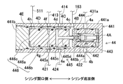
- FIG. 1 is a diagram illustrating a schematic configuration of a vehicle braking control device according to the present embodiment and a vehicle braking device that can be controlled by the vehicle braking control device. It is a figure which shows the detailed structure of the servo pressure generator of the braking device for vehicles of FIG. It is a flowchart for demonstrating operation
- (a) is a figure which shows a time-dependent change of vehicle speed
- (b) is a figure which shows a time-dependent change of the operation amount of a brake pedal
- (C) is a figure which shows a time-dependent change of braking force
- (d) is a figure which shows a time-dependent change of servo hydraulic pressure. It is a figure which shows the relationship between the hydraulic pressure of the brake fluid in the servo chamber of a master cylinder, and the liquid quantity of the brake fluid in a wheel cylinder.
- the vehicle braking device includes a hydraulic braking force generator BF that generates hydraulic braking force on wheels 5FR, 5FL, 5RR, and 5RL, and a regenerative braking force on driving wheels, for example, left and right front wheels 5FR and 5FL. And a regenerative braking force generator BM and the like to be generated.
- the vehicle braking control device includes a brake ECU 6 that controls the hydraulic braking force generator BF, a hybrid ECU 8 that controls the regenerative braking force generator BM, and the like.
- the hydraulic braking force generation device BF includes a master cylinder 1, a reaction force generation device 2, a separation lock valve 22, a reaction force valve 23, a servo pressure generation device 4, a hydraulic pressure control unit 5, and various sensors 71 ⁇ . 76 or the like.
- the master cylinder 1 is a part that supplies hydraulic fluid to the hydraulic pressure control unit 5 in accordance with an operation amount of a brake pedal 10 (corresponding to “brake operation means”), and includes a main cylinder 11, a cover cylinder 12, and an input piston 13.
- the first master piston 14 (corresponding to “output piston”), the second master piston 15 (corresponding to “output piston”), and the like.
- the main cylinder 11 is a bottomed, generally cylindrical housing that is closed at the front and opened to the rear.
- An inner wall 111 that protrudes in an inward flange shape is provided near the rear of the inner periphery of the main cylinder 11.
- the center of the inner wall 111 is a through hole 111a that penetrates in the front-rear direction.
- small-diameter portions 112 (rear) and 113 (front) whose inner diameter is slightly smaller are provided in front of the inner wall 111 inside the main cylinder 11. That is, the small diameter portions 112 and 113 project inwardly from the inner peripheral surface of the main cylinder 11.
- a first master cylinder 14 is disposed so as to be slidable in contact with the small diameter portion 112 and movable in the axial direction.
- a second master cylinder 15 is disposed so as to be slidable in contact with the small diameter portion 113 and movable in the axial direction.
- the cover cylinder 12 includes a substantially cylindrical cylinder portion 121, a bellows cylindrical boot 122, and a cup-shaped compression spring 123.
- the cylinder part 121 is disposed on the rear end side of the main cylinder 11 and is coaxially fitted in the opening on the rear side of the main cylinder 11.
- the inner diameter of the front part 121 a of the cylinder part 121 is set larger than the inner diameter of the through hole 111 a of the inner wall part 111. Further, the inner diameter of the rear part 121b of the cylinder part 121 is made smaller than the inner diameter of the front part 121a.
- the dust-proof boot 122 has a bellows-like shape and can be expanded and contracted in the front-rear direction.
- a through hole 122 a is formed in the center of the rear of the boot 122.
- the compression spring 123 is a coil-shaped biasing member disposed around the boot 122, and the front side thereof abuts on the rear end of the main cylinder 11, and the rear side is compressed so as to be close to the through hole 122 a of the boot 122. It is a diameter.
- the rear end of the boot 122 and the rear end of the compression spring 123 are coupled to the operation rod 10a.
- the compression spring 123 biases the operation rod 10a backward.
- the input piston 13 is a piston that slides in the cover cylinder 12 in accordance with the operation of the brake pedal 10.
- the input piston 13 is a bottomed substantially cylindrical piston having a bottom surface at the front and an opening at the rear.
- the bottom wall 131 constituting the bottom surface of the input piston 13 has a larger diameter than other portions of the input piston 13.
- the input piston 13 is axially slidable and liquid-tightly arranged at the rear part 121 b of the cylinder part 121, and the bottom wall 131 enters the inner peripheral side of the front part 121 a of the cylinder part 121.
- an operation rod 10a that is linked to the brake pedal 10 is disposed in the input piston 13, an operation rod 10a that is linked to the brake pedal 10 is disposed.
- the pivot 10b at the tip of the operation rod 10a can push the input piston 13 forward.
- the rear end of the operation rod 10 a protrudes outside through the opening on the rear side of the input piston 13 and the through hole 122 a of the boot 122, and is connected to the brake pedal 10.
- the operation rod 10a moves forward while pushing the boot 122 and the compression spring 123 in the axial direction.
- the input piston 13 also moves forward.
- the first master piston 14 is disposed on the inner wall 111 of the main cylinder 11 so as to be slidable in the axial direction.
- the first master piston 14 is formed integrally with a pressurizing cylinder portion 141, a flange portion 142, and a protruding portion 143 in order from the front side.
- the pressure cylinder 141 is formed in a substantially cylindrical shape with a bottom having an opening on the front, has a gap with the inner peripheral surface of the main cylinder 11, and is in sliding contact with the small-diameter portion 112.
- a coil spring-like urging member 144 is disposed in the internal space of the pressure cylinder portion 141 between the second master piston 15. The first master piston 14 is urged rearward by the urging member 144.
- the collar part 142 has a larger diameter than the pressure cylinder part 141 and is in sliding contact with the inner peripheral surface of the main cylinder 11.
- the protrusion 143 has a smaller diameter than the flange 142 and is disposed so as to slide in a liquid-tight manner in the through hole 111 a of the inner wall 111.
- the rear end of the protruding portion 143 passes through the through hole 111 a and protrudes into the internal space of the cylinder portion 121 and is separated from the inner peripheral surface of the cylinder portion 121.
- the rear end surface of the protrusion 143 is separated from the bottom wall 131 of the input piston 13, and the separation distance d can be changed.
- the first pressurizing chamber 1D is defined by the inner peripheral surface of the main cylinder 11, the front side of the pressurizing cylinder portion 141 of the first master piston 14, and the rear side of the second master piston 15.
- the rear chamber behind the first pressurizing chamber 1D is defined by the inner peripheral surface (inner peripheral portion) of the main cylinder 11, the small-diameter portion 112, the front surface of the inner wall 111, and the outer peripheral surface of the first master piston 14. ing.
- the front end portion and the rear end portion of the flange portion 142 of the first master piston 14 divide the rear chamber into the front and rear, a reaction force chamber 1C (corresponding to “front chamber”) is defined on the front side, and the servo on the rear side.
- Chamber 1A is partitioned.
- the inner peripheral part and rear surface of the inner wall part 111 of the main cylinder 11, the inner peripheral surface (inner peripheral part) of the front part 121a of the cylinder part 121, the protrusion part 143 (rear end part) of the first master piston 14, and the input piston A separation chamber 1 ⁇ / b> B (corresponding to a “rear chamber”) is partitioned by 12 front end portions.
- the second master piston 15 is disposed on the front side of the first master piston 14 in the main cylinder 11 so as to be in sliding contact with the small diameter portion 113 and movable in the axial direction.
- the second master piston 15 is integrally formed with a cylindrical pressure cylinder portion 151 having an opening in the front and a bottom wall 152 that closes the rear side of the pressure cylinder portion 151.
- the bottom wall 152 supports the biasing member 144 between the first master piston 14.
- a coil spring-like urging member 153 is disposed in the internal space of the pressure cylinder portion 151 between the inner bottom surface 111d of the main cylinder 11 closed.
- the second master piston 15 is urged rearward by the urging member 153.
- the second pressurizing chamber 1 ⁇ / b> E is defined by the inner peripheral surface and the inner bottom surface 111 d of the main cylinder 11 and the pressurizing cylinder portion 151 of the second master piston 15.
- the master cylinder 1 is formed with ports 11a to 11i that communicate between the inside and the outside.
- the port 11 a is formed behind the inner wall 111 in the main cylinder 11.
- the port 11b is formed opposite to the port 11a at the same position in the axial direction as the port 11a.
- the port 11 a and the port 11 b communicate with each other via an annular space between the inner peripheral surface of the main cylinder 11 and the outer peripheral surface of the cylinder part 121.
- the port 11 a and the port 11 b are connected to the pipe 161 and to the reservoir 171.
- the port 11b communicates with the separation chamber 1B through a passage 18 formed in the cylinder portion 121 and the input piston 13.
- the passage 18 is blocked when the input piston 13 moves forward, thereby blocking the separation chamber 1B and the reservoir 171.
- the port 11c is formed in front of the port 11a, and communicates the separation chamber 1B and the pipe 162.
- the port 11d is formed in front of the port 11c, and communicates the servo chamber 1A and the pipe 163.
- the port 11e is formed in front of the port 11d, and communicates the reaction force chamber 1C with the pipe 164.
- the port 11f is formed between the seal members 91 and 92 of the small-diameter portion 112 and communicates the reservoir 172 and the inside of the main cylinder 11.
- the port 11 f communicates with the first pressurizing chamber 1 ⁇ / b> D via a passage 145 formed in the first master piston 14.
- the passage 145 is formed at a position where the port 11f and the first pressurizing chamber 1D are blocked when the first master piston 14 moves forward.
- the port 11g is formed in front of the port 11f and communicates the first pressurizing chamber 1D with the pipe 51.
- the port 11 h is formed between the seal members 93 and 94 of the small diameter portion 113 and communicates the reservoir 173 and the inside of the main cylinder 11.
- the port 11g communicates with the second pressurizing chamber 1E via a passage 154 formed in the second master piston 15.
- the passage 154 is formed at a position where the port 11g and the second pressurizing chamber 1E are blocked when the second master piston 15 moves forward.
- the port 11i is formed in front of the port 11h, and communicates the second pressurizing chamber 1E and the pipe 52.
- a sealing member such as an O-ring (black circle portion in the drawing) is appropriately disposed.
- the seal members 91 and 92 are disposed in the small diameter portion 112 and are in liquid-tight contact with the outer peripheral surface of the first master piston 14.
- the seal members 93 and 94 are disposed in the small-diameter portion 113 and are in liquid-tight contact with the outer peripheral surface of the second master piston 15.
- Seal members 95 and 96 are also arranged between the input piston 13 and the cylinder part 121.
- the stroke sensor 71 is a sensor that detects an operation amount (stroke amount) by which the brake pedal 10 is operated by the driver, and transmits a detection signal to the brake ECU 6.
- the brake switch 72 is a switch that detects whether or not the brake pedal 10 is operated by the driver using a binary signal, and transmits a detection signal to the brake ECU 6.
- the reaction force generator 2 is a device that generates a reaction force that opposes the operation force when the brake pedal 10 is operated, and is configured mainly with a stroke simulator 21.
- the stroke simulator 21 generates reaction force hydraulic pressure in the separation chamber 1B and the reaction force chamber 1C according to the operation of the brake pedal 10.
- the stroke simulator 21 is configured such that a piston 212 is slidably fitted to a cylinder 211.
- the piston 212 is urged forward by a compression spring 213, and a reaction force hydraulic chamber 214 is formed on the front side of the piston 212.
- the reaction force hydraulic chamber 214 is connected to the reaction force chamber 1C via the pipe 164 and the port 11e, and the reaction force hydraulic pressure chamber 214 is connected to the separation lock valve 22 and the reaction force valve 23 via the pipe 164. Has been.
- the separation lock valve 22 is an electromagnetic valve having a structure that is closed in a non-energized state, and opening / closing thereof is controlled by the brake ECU 6.
- the separation lock valve 22 is connected between the pipe 164 and the pipe 162.
- the pipe 164 communicates with the reaction force chamber 1C through the port 11e
- the pipe 162 communicates with the separation chamber 1B through the port 11c.
- the separation lock valve 22 is opened, the separation chamber 1B is opened, and when the separation lock valve 22 is closed, the separation chamber 1B is sealed. Accordingly, the pipe 164 and the pipe 162 are provided so as to communicate the separation chamber 1B and the reaction force chamber 1C.
- the separation lock valve 22 is closed in a non-energized state where power is not supplied, and at this time, the separation chamber 1B and the reaction force chamber 1C are shut off. As a result, the separation chamber 1B is hermetically sealed and there is no place for the hydraulic fluid, and the input piston 13 and the first master piston 14 are interlocked with each other while maintaining a constant separation distance d. In addition, the separation lock valve 22 is opened in the energized state, and at this time, the separation chamber 1B and the reaction force chamber 1C are communicated. Thereby, the volume change of the separation chamber 1B and the reaction force chamber 1C accompanying the advance and retreat of the first master piston 14 is absorbed by the movement of the hydraulic fluid.
- the pressure sensor 73 is a sensor that detects the reaction force hydraulic pressure in the reaction force chamber 1 ⁇ / b> C, and is connected to the pipe 164.
- the pressure sensor 73 detects the pressure of the reaction force chamber 1C when the separation lock valve 22 is closed, and also detects the pressure of the separated separation chamber 1B when the separation lock valve 22 is open. become.
- the pressure sensor 73 transmits a detection signal to the brake ECU 6.
- the reaction valve 23 is an electromagnetic valve having a structure that opens in a non-energized state, and opening and closing of the reaction valve 23 is controlled by the brake ECU 6.
- the reaction force valve 23 is connected between the pipe 164 and the pipe 161.
- the pipe 164 communicates with the reaction force chamber 1C through the port 11e
- the pipe 161 communicates with the reservoir 171 through the port 11a.
- the reaction force valve 23 communicates between the reaction force chamber 1 ⁇ / b> C and the reservoir 171 in a non-energized state and does not generate a reaction force hydraulic pressure, but shuts off in an energized state to generate a reaction force hydraulic pressure.
- the servo hydraulic pressure generator 4 includes a pressure reducing valve 41, a pressure increasing valve 42, a high pressure supply unit 43, a regulator 44, and the like.
- the pressure reducing valve 41 is an electromagnetic valve having a structure that opens in a non-energized state, and the flow rate is controlled by the brake ECU 6.
- One side of the pressure reducing valve 41 is connected to the pipe 161 via the pipe 411, and the other side of the pressure reducing valve 41 is connected to the pipe 413. That is, one of the pressure reducing valves 41 communicates with the reservoir 171 through the pipes 411 and 161 and the ports 11a and 11b.
- the pressure increasing valve 42 is an electromagnetic valve having a structure that is closed in a non-energized state, and the flow rate is controlled by the brake ECU 6.
- One of the pressure increasing valves 42 is connected to the pipe 421, and the other of the pressure increasing valves 42 is connected to the pipe 422.
- the high-pressure supply unit 43 is a part that supplies high-pressure hydraulic fluid to the regulator 44.
- the high pressure supply unit 43 includes an accumulator 431, a hydraulic pump 432, a motor 433, a reservoir 434, and the like.
- the accumulator 431 is a tank that accumulates high-pressure hydraulic fluid.
- the accumulator 431 is connected to the regulator 44 and the hydraulic pump 432 by a pipe 431a.
- the hydraulic pump 432 is driven by the motor 433 and pumps the hydraulic fluid stored in the reservoir 434 to the accumulator 431.
- the pressure sensor 75 provided in the pipe 431a detects the accumulator hydraulic pressure of the accumulator 431, and transmits a detection signal to the brake ECU 6.
- the accumulator hydraulic pressure correlates with the accumulated amount of hydraulic fluid accumulated in the accumulator 431.
- the motor 433 When the pressure sensor 75 detects that the accumulator hydraulic pressure has dropped below a predetermined value, the motor 433 is driven based on a command from the brake ECU 6. As a result, the hydraulic pump 432 pumps the hydraulic fluid to the accumulator 431 and recovers the accumulator hydraulic pressure to a predetermined value or higher.
- FIG. 2 is a partial cross-sectional explanatory view showing the internal structure of the regulator 44 constituting the servo hydraulic pressure generator 4.
- the regulator 44 includes a cylinder 441, a ball valve 442, an urging portion 443, a valve seat portion 444, a control piston 445, a sub piston 446, and the like.
- the cylinder 441 includes a substantially bottomed cylindrical cylinder case 441a having a bottom surface on one side (right side in the drawing) and a lid member 441b that closes an opening (left side in the drawing) of the cylinder case 441a.
- the lid member (441b) is formed in a U-shaped cross section.
- the lid member 441b is formed in a columnar shape, and a portion blocking the opening of the cylinder case 441a is the lid member 441b. Will be described.
- the cylinder case 441a is formed with a plurality of ports 4a to 4h for communicating the inside and the outside.
- the port 4a is connected to the pipe 431a.
- the port 4b is connected to the pipe 422.
- the port 4 c is connected to the pipe 163.
- the port 4d is connected to the pipe 161 via the pipe 414.
- the port 4 e is connected to the pipe 424 and further connected to the pipe 422 via the relief valve 423.
- the port 4f is connected to the pipe 413.
- the port 4g is connected to the pipe 421.
- the port 4 h is connected to a pipe 511 branched from the pipe 51.
- the ball valve 442 is a ball type valve and is disposed on the bottom surface side of the cylinder case 441a inside the cylinder 441 (hereinafter also referred to as the cylinder bottom surface side).
- the urging portion 443 is a spring member that urges the ball valve 442 toward the opening side of the cylinder case 441a (hereinafter also referred to as the cylinder opening side), and is installed on the bottom surface of the cylinder case 441a.
- the valve seat portion 444 is a wall member provided on the inner peripheral surface of the cylinder case 441a, and partitions the cylinder opening side and the cylinder bottom surface side.
- a through passage 444 a is formed in the center of the valve seat portion 444 to communicate the partitioned cylinder opening side and cylinder bottom side.
- the valve member 444 holds the ball valve 442 from the cylinder opening side in such a manner that the biased ball valve 442 closes the through passage 444a.
- a space defined by the ball valve 442, the urging portion 443, the valve seat portion 444, and the inner peripheral surface of the cylinder case 441a on the cylinder bottom surface side is defined as a first chamber 4A.
- the first chamber 4A is filled with hydraulic fluid, connected to the pipe 431a via the port 4a, and connected to the pipe 422 via the port 4b.
- the control piston 445 includes a substantially cylindrical main body 445a and a substantially cylindrical protrusion 445b having a smaller diameter than the main body 445a.
- the main body 445a is disposed on the cylinder opening side of the valve seat 444 so as to be slidable in the axial direction in a coaxial and liquid-tight manner.
- the main body 445a is biased toward the cylinder opening by a biasing member (not shown).
- a passage 445c extending in the radial direction (vertical direction in the drawing) with both ends opened to the peripheral surface of the main body 445a is formed at the approximate center of the main body 445a in the cylinder axis direction.
- a part of the inner peripheral surface of the cylinder 441 corresponding to the opening position of the passage 445c has a port 4d and is recessed in a concave shape. Let this hollow space be the 3rd chamber 4C.
- the protruding portion 445b protrudes from the center of the cylinder bottom end surface of the main body portion 445a toward the cylinder bottom surface.
- the diameter of the protruding portion 445 b is smaller than the through passage 444 a of the valve seat portion 444.
- the protruding portion 445b is arranged coaxially with the through passage 444a.
- the tip of the protrusion 445b is spaced from the ball valve 442 toward the cylinder opening by a predetermined distance.
- the protrusion 445b is formed with a passage 445d that extends in the cylinder axial direction and opens in the center of the cylinder bottom end surface of the protrusion 445b.
- the passage 445d extends into the main body 445a and is connected to the passage 445c.
- the space defined by the cylinder bottom end surface of the main body 445a, the outer surface of the protruding portion 445b, the inner peripheral surface of the cylinder 441, the valve seat 444, and the ball valve 442 is defined as a second chamber 4B.
- the second chamber 4B communicates with the ports 4d and 4e via the passages 445c and 445d and the third chamber 4C.
- the sub-piston 446 includes a sub main body 446a, a first protrusion 446b, and a second protrusion 446c.
- the sub main body 446a is formed in a substantially cylindrical shape.
- the sub main body 446a is disposed coaxially, liquid-tightly, and slidable in the axial direction on the cylinder opening side of the main body 445a.
- the first projecting portion 446b has a substantially cylindrical shape having a smaller diameter than the sub main body portion 446a, and projects from the center of the end surface of the sub main body portion 446a on the cylinder bottom surface side.
- the first protrusion 446b is in contact with the cylinder opening side end surface of the main body 445a.
- the 2nd protrusion part 446c is the same shape as the 1st protrusion part 446b, and protrudes from the end surface center by the side of the cylinder opening of the sub main-body part 446a.
- the second protrusion 446c is in contact with the lid member 441b.
- the space defined by the end surface on the cylinder bottom surface side of the sub main body portion 446a, the outer surface of the first projecting portion 446b, the end surface on the cylinder opening side of the control piston 445, and the inner peripheral surface of the cylinder 441 is defined as a pressure control chamber 4D.
- the pressure control chamber 4D communicates with the pressure reducing valve 41 through the port 4f and the pipe 413, and communicates with the pressure increasing valve 42 through the port 4g and the pipe 421.
- a space defined by the end face on the cylinder opening side of the sub main body 446a, the outer surface of the second protrusion 446c, the lid member 441b, and the inner peripheral surface of the cylinder 441 is defined as a fourth chamber 4E.
- the fourth chamber 4E communicates with the port 11g through the port 4h and the pipes 511 and 51.
- Each chamber 4A-4E is filled with hydraulic fluid.
- the pressure sensor 74 is a sensor that detects the servo fluid pressure (drive fluid pressure) supplied to the servo chamber 1A, and is connected to the pipe 163 (shown in FIG. 1). The pressure sensor 74 transmits a detection signal to the brake ECU 6.
- Wheel cylinders 541 to 544 communicate with the first pressurizing chamber 1D and the second pressurizing chamber 1E that generate the master cylinder pressure via pipes 51 and 52 and an ABS (Antilock Bracket System) 53, respectively.
- the wheel cylinders 541 to 544 constitute the brake 5 of the wheels 5FR to 5RL.
- a known ABS 53 is connected to the port 11g of the first pressurizing chamber 1D and the port 11i of the second pressurizing chamber 1E via pipes 51 and 52, respectively.
- Wheel cylinders 541 to 544 for operating a brake device for braking the wheels 5FR to 5RL are connected to the ABS 53.
- the regenerative braking force generator BM converts, for example, an AC synchronous motor 91 connected to an axle connecting both front wheels 5FR and 5FL, and AC power generated by the motor 91 into DC power and charges the battery 93. And an inverter 92 that converts the direct current of the battery 93 into an alternating current and supplies the alternating current to the motor 91.
- the brake ECU 6 is an electronic control unit, and includes a microcomputer.
- the microcomputer includes a storage unit such as an input / output interface, a CPU, a RAM, a ROM, and a nonvolatile memory connected to each other via a bus. Yes.
- the brake ECU 6 is connected to various sensors 71 to 76 in order to control the electromagnetic valves 22, 23, 41, 42, the motor 433, and the like.
- the brake ECU 6 receives an operation amount (stroke amount) of the brake pedal 10 from the stroke sensor 71 by the driver, inputs whether or not the driver operates the brake pedal 10 from the brake switch 72, and receives a reaction force from the pressure sensor 73.
- the reaction force hydraulic pressure of the chamber 1C or the pressure of the separation chamber 1B is input, the servo hydraulic pressure (driving hydraulic pressure) supplied from the pressure sensor 74 to the servo chamber 1A is input, and the accumulator hydraulic pressure of the accumulator 431 is input from the pressure sensor 75. Is input from the wheel speed sensor 76, and the speeds of the wheels 5FR, 5FL, 5RR, and 5RL are input.
- the brake ECU 6 is connected to the hybrid ECU 8 so as to communicate with each other, and the required braking force is generated by the target regenerative braking force generated by the regenerative braking force generation device 9 and the target fluid generated by the hydraulic braking force generation device 7. Cooperative control (regenerative cooperative control) is performed so as to be equal to the sum of the pressure braking force.
- the brake ECU 6 stores two control modes of “linear mode” and “regulator mode”.
- Hybrid ECU 8 manages the state of charge of the battery 93 and executes regenerative brake control in cooperation with the brake ECU 6. That is, power is generated by driving the motor 91 with the rotational force of both front wheels 5FR and 5FL, and the battery 93 is charged with the obtained electric power. Then, the regenerative braking force generated by the resistance force of the motor 91 during power generation is obtained and output to the brake ECU 6.
- the brake ECU 6 has a linear mode and a regulator mode as operation modes of the master cylinder device 100 to be controlled.
- the linear mode is a hydraulic brake control mode selected for a normal vehicle running state. In the linear mode, when the braking force corresponding to the operation amount of the brake pedal 10 cannot be generated only by the regenerative brake device, the first and second master pistons 14 and 15 are driven by the servo hydraulic pressure generating device 4, and the shortage A hydraulic braking force corresponding to the braking force is generated.
- the regulator mode is a hydraulic brake control mode selected when an abnormality occurs. In the regulator mode, the separation chamber 1B is sealed, and the pistons 13, 14, 15 are driven by the driver's operating force to generate a hydraulic braking force.
- the linear mode to which the present invention is applied will be described in detail.
- the brake ECU 6 In the linear mode, the brake ECU 6 energizes the separation lock valve 22 to open, and energizes the reaction force valve 23 to close the valve.
- the reaction valve 23 When the reaction valve 23 is closed, the reaction chamber 1C and the reservoir 171 are shut off, and when the separation lock valve 22 is opened, the separation chamber 1B and the reaction chamber 1C communicate with each other.
- the ball valve 442 of the servo hydraulic pressure generating device 4 is in a state of closing the through passage 444a of the valve seat portion 444.
- the pressure reducing valve 41 is opened, the pressure increasing valve 42 is closed, and the first chamber 4A and the second chamber 4B are shut off.
- the second chamber 4B communicates with the servo chamber 1A via the pipe 163 and is kept at the same pressure.
- the second chamber 4B communicates with the third chamber 4C via the passages 445c and 445d of the control piston 445, and further communicates with the reservoir 171 via the pipes 414 and 161.
- One of the pressure control chambers 4 ⁇ / b> D is closed by the pressure increasing valve 42, and the other is communicated with the reservoir 171 and the second chamber 4 ⁇ / b> B via the pressure reducing valve 41.
- the fourth chamber 4E communicates with the first pressurizing chamber 1D via the pipes 511 and 51 and is maintained at the same pressure.
- no servo hydraulic pressure is generated in the servo chamber 1A
- no master cylinder hydraulic pressure is generated in the first pressurizing chamber 1D.
- the stroke simulator 21 When the brake pedal 10 is depressed from this state, the input piston 13 moves forward, the passage 18 is divided, and the reservoir 171 and the separation chamber 1B are shut off. In response to the movement of the first master piston 14, the same amount of liquid flows into and out of the reaction chamber 1C from the separation chamber 1B by the protrusion 143. Then, the stroke simulator 21 generates a reaction force pressure corresponding to the stroke amount in the separation chamber 1B and the reaction force chamber 1C. That is, the stroke simulator 21 applies a reaction force pressure corresponding to the stroke amount of the input piston 13 (the operation amount of the brake pedal 10) to the brake pedal 10 connected to the input piston 13.
- the area of the front end surface of the protrusion 143 and the area of the surface where the collar 142 faces the reaction force chamber 1C are the same. Therefore, when the reaction force valve 23 is closed and the separation lock valve 22 is open, the internal pressures of the separation chamber 1B and the reaction force chamber 1C are the same, and therefore the reaction force pressure of the separation chamber 1B protrudes.
- the force acting on the tip surface of the portion 143 is the same as the force acting on the surface where the reaction force pressure of the reaction force chamber 1C faces the reaction force chamber 1C, and the driver depresses the brake pedal 10, and the separation chamber 1B and reaction force Even if the internal pressure of the chamber 1C increases, the first master piston 14 does not move.
- the brake ECU 6 and the hybrid ECU 8 control the hydraulic braking force generator BF and the regenerative braking force generator BM to apply the target braking force to the wheels 5FR, 5FL, 5RR, 5RL.
- the brake ECU 6 and the hybrid ECU 8 perform control to preferentially use the regenerative braking force generator BM. That is, the brake ECU 6 calculates a target value (target regeneration amount) of the regeneration amount, and outputs the target regeneration amount to the hybrid ECU 8.
- the hybrid ECU 8 calculates a regeneration amount (execution regeneration amount) to be executed with respect to the target regeneration amount, and outputs the execution regeneration amount to the brake ECU 6.
- the brake ECU 6 calculates the insufficient braking force by subtracting the regenerative braking force corresponding to the execution regeneration amount from the target braking force, and controls the hydraulic braking force generator BF so as to generate the insufficient braking force.
- the accumulator 431 and the pressure control chamber 4 ⁇ / b> D communicate with each other by opening the pressure increasing valve 42.
- the pressure control chamber 4D and the reservoir 171 are shut off.
- the hydraulic pressure in the pressure control chamber 4D can be increased by the high-pressure hydraulic fluid supplied from the accumulator 431.
- the control piston 445 slides toward the cylinder bottom surface.
- the tip of the protrusion 445 b of the control piston 445 contacts the ball valve 442, and the passage 445 d is closed by the ball valve 442. Then, the second chamber 4B and the reservoir 171 are shut off.
- the ball valve 442 is pushed toward the cylinder bottom surface by the protruding portion 445b and moves, and the ball valve 442 is separated from the valve seat portion 444.
- the first chamber 4A and the second chamber 4B communicate with each other through the through passage 444a of the valve seat portion 444.
- High pressure hydraulic fluid is supplied from the accumulator 431 to the first chamber 4A, and the pressure in the second chamber 4B communicating with the first chamber 4A also increases.
- the servo fluid pressure in the communicating servo chamber 1A also increases.
- the first master piston 14 moves forward, and the master cylinder hydraulic pressure in the first pressurizing chamber 1D increases.
- the second master piston 15 also moves forward, and the master cylinder hydraulic pressure in the second pressurizing chamber 1E increases.
- high-pressure hydraulic fluid is supplied to the wheel cylinders 541 to 544 via the pipes 51 and 52 and the hydraulic pressure control unit 5, and hydraulic braking force is applied to the wheels 5FR to 5RL.
- the master cylinder hydraulic pressure in the first pressurizing chamber 1D is fed back to the fourth chamber 4E of the servo hydraulic pressure generator 4.
- the pressure in the fourth chamber 4E rises and balances with the hydraulic pressure in the pressure control chamber 4D, and the sub piston 446 does not move. In this manner, a hydraulic braking force commensurate with the insufficient braking force can be generated based on the servo hydraulic pressure generated from the high pressure of the accumulator 431.
- the pressure reducing valve 41 When releasing the generation of the hydraulic braking force, the pressure reducing valve 41 is opened and the pressure increasing valve 42 is closed, so that the reservoir 171 communicates with the pressure control chamber 4D. As a result, the control piston 445 moves backward, and the servo hydraulic pressure generator 4 returns to the state before the brake pedal 10 is depressed.
- the first and second master pistons 14 and 15 are advanced in a state where the depression of the brake pedal 10 is maintained, that is, in a state where the input piston 13 of the master cylinder 1 is stopped.
- the first and second master pistons 14 and 15 are moved forward faster than the input piston 13, the volume of the reaction force chamber 1C is reduced, the volume of the separation chamber 1B is increased, and the brake fluid in the reaction force chamber 1C is piped. It flows into the separation chamber 1B through 162,164.
- the wheel cylinders 541 to 544 are in the initial stage of low-speed switching.
- the increase amount of the brake fluid amount Q in the wheel cylinders 541 to 544 with respect to the increase in the brake fluid pressure P in the servo chamber 1A of the master cylinder 1 is as shown in FIG. There is a gradual increase.
- the brake fluid pressure P in the servo chamber 1A of the master cylinder 1 is set to fluid pressures Pb to Pa (Pb ⁇ Pa), and the brake fluid amount Q in the wheel cylinders 541 to 544 is set to the consumed fluid amount Qb to Unless Qa (Qb ⁇ Qa) is satisfied, the hydraulic braking force is not generated or hardly generated in the wheels 5FR, 5FL, 5RR, and 5RL, and the vehicle deceleration G cannot be increased as shown in FIG. 5B. This slows down the hydraulic braking response.
- the brake ECU 6 described above drives the first and second master pistons 14 and 15 forward to suppress the pull-in of the brake pedal 10 and improve the operation feeling of the brake pedal 10.
- the forward speed of the first and second master pistons 14 and 15 is set to a predetermined speed (hereinafter referred to as “set”) so that the brake pedal 10 is prevented from being pulled.
- Speed " a predetermined speed
- the brake ECU 6 advances the first and second master pistons 14 and 15 at the set speed before increasing the hydraulic braking force, so that the inside of the wheel cylinders 541 to 544 is increased. Increase the amount of brake fluid.
- the brake ECU 6 takes in each sensor signal, for example, a detection signal from the stroke sensor 71, the wheel speed sensor 76, and the like, and also takes in an execution regenerative braking force from the hybrid ECU 8, and determines whether regenerative coordination is in progress. to decide.
- step S2 if the regeneration coordination is not being performed, the process is terminated. If the regeneration coordination is being performed, the operation amount with respect to the brake pedal 10 is maintained at a constant amount in step S3, that is, the brake pedal by the driver. It is determined whether or not the depression of 10 is held (corresponding to “holding state determination means”). The reason for performing the determination in step S3 is that when the brake pedal 10 is retracted while the operation amount of the brake pedal 10 is maintained at a constant amount, the brake pedal is operated while the operation amount of the brake pedal 10 is increased or decreased. This is because the operation feeling of the brake pedal 10 is worse than when 10 is pulled.
- step S3 the brake ECU 6 proceeds to step S9 when the driver depresses or returns the brake pedal 10. On the other hand, when the depression of the brake pedal 10 by the driver is maintained, the process proceeds to step S6.
- step S6 the brake ECU 6 determines that the amount of brake fluid in the wheel cylinders 541 to 544 is such that the hydraulic braking force is not generated or hardly generated in the wheels 5FR, 5FL, 5RR, 5RL corresponding thereto, and Then, it is determined that an increase in the hydraulic braking force to be generated in the wheels 5FR, 5FL, 5RR, 5RL corresponding to the wheel cylinders 541 to 544 is predicted.
- the brake ECU 6 compares the vehicle speed V obtained from the detection signal of the wheel speed sensor 76 with a preset drive start speed Vi, and ends the process when the vehicle speed V is higher than the drive start speed Vi. To do.
- the amount of brake fluid in the wheel cylinders 541 to 544 generates little or almost no hydraulic braking force on the wheels 5FR, 5FL, 5RR, 5RL corresponding thereto. It is determined that an increase in the hydraulic braking force to be generated in the wheels 5FR, 5FL, 5RR, and 5RL corresponding to the wheel cylinders 541 to 544 is predicted (corresponding to “braking determination means”). ), Go to step S7.
- step S7 the brake ECU 6 starts to increase the predicted hydraulic braking force according to the time from the determination that the increase in the hydraulic braking force is predicted to the start of the predicted increase in the hydraulic braking force.
- the forward speeds of the first and second master pistons 14 and 15 are set again so that the amount of liquid (for example, Qa) to be supplied to the wheel cylinders 541 to 544 is supplied by the time (“forward speed setting means") Equivalent to).
- the brake ECU 6 divides the value obtained by subtracting the switching start speed Vs from the drive start speed Vi by the deceleration to derive the time from the above determination time to the increase start time, and at the time when the predicted increase in the decompression braking force starts.
- the amount of brake fluid to be supplied to the wheel cylinders 541 to 544 is divided by the derived time to derive the amount of fluid to be supplied from the master cylinder 1 to the wheel cylinders 541 to 544 per unit time.
- the forward speeds of the first and second master pistons 14 and 15 corresponding to the liquid amount thus set are set as the set speed. Then, the brake ECU 6 proceeds to step S8.
- step S8 the brake ECU 6 advances the first and second master pistons 14 and 15 at the set speed set in step S7.
- step S9 the brake ECU 6 determines whether or not the vehicle speed V obtained from the detection signal of the wheel speed sensor 76 has been reduced to the switching start speed Vs, and when the vehicle speed V has decreased to the switching start speed Vs, In step S10, the amount of brake fluid supplied from the master cylinder 1 to the wheel cylinders 541 to 544 is increased, and the process ends.
- the hydraulic fluid braking force in the wheel cylinders 541 to 544 When the vehicle speed V becomes the driving start speed Vi at the time t4, the hydraulic fluid braking force in the wheel cylinders 541 to 544 generates no or almost no hydraulic braking force on the corresponding wheels 5FR, 5FL, 5RR, 5RL. Since it is determined that the hydraulic pressure is increased and the increase in the hydraulic braking force is predicted, the set speed is set according to the time from the increase prediction determination time t4 to the increase start time t6 of the hydraulic braking force. The first and second master pistons 14 and 15 move forward, and the brake fluid is gradually supplied from the master cylinder 1 to the wheel cylinders 541 to 544 at a level at which no deceleration due to the hydraulic braking force occurs (step S8 in FIG. 3). ). Thereby, since the pull-in of the brake pedal 10 is suppressed, the operational feeling of the brake pedal 10 can be improved.
- the hydraulic pressure P of the brake fluid in the servo chamber 1A of the master cylinder 1 is slightly earlier than the hydraulic braking force increase start time t6 from the hydraulic braking force increase prediction determination time t4 (start of increasing hydraulic braking force).
- the hydraulic pressure P in the servo chamber 1A is gradually increased to Pb at time t6, and is maintained at the hydraulic pressure Pb from time t5 to time t6 when the hydraulic braking force starts to increase (FIG. 4 ( d)).
- the brake fluid amount Q in the wheel cylinders 541 to 544 is reliably increased to Qb at the time t6 when the hydraulic braking force starts to increase, the responsiveness when the hydraulic braking force increases can be improved (FIG. 5A, see FIG. 5B).
- the time point at which the servo hydraulic pressure Pb is reached may be set to be the increase start time point t6 of the hydraulic braking force.
- the amount of brake fluid in the wheel cylinders 541 to 544 is the amount of fluid that does not generate or hardly generates the hydraulic braking force in the wheels 5FR, 5FL, 5RR, and 5RL corresponding thereto.
- an increase in the hydraulic braking force to be generated in the wheels 5FR, 5FL, 5RR, 5RL corresponding to the wheel cylinders 541 to 544 is predicted.
- the amount of brake fluid in the wheel cylinders 541 to 544 is reduced by the start of the predicted increase in the hydraulic braking force while maintaining the set speed for moving the first and second master pistons 14 and 15 low. Since it can increase reliably, the responsiveness at the time of increase of a hydraulic braking force can be improved further, maintaining the operation feeling of the brake pedal 10.
- the brake ECU 6 determines that the increase of the hydraulic braking force is predicted until the start of the increase of the predicted hydraulic braking force according to the time from the determination that the increase of the hydraulic braking force is predicted to the start of the increase of the predicted hydraulic braking force.
- the forward speeds of the first and second master pistons 14 and 15 are set again so that the amount of liquid to be supplied to the wheel cylinders 541 to 544 is supplied. In this way, by adjusting the amount of brake fluid in the wheel cylinders 541 to 544 and the set speeds of the first and second master pistons 14 and 15 at the start of an increase in the predicted hydraulic braking force, the brake pedal 10 It is possible to more suitably achieve both the operational feeling improvement and the response improvement of the hydraulic braking force.
- the brake ECU 6 advances the first and second master pistons 14 and 15 at the set speed that has been set.
- the brake fluid is gradually supplied from the master cylinder 1 to the wheel cylinders 541 to 544 at a level at which no deceleration due to the hydraulic braking force occurs.
- the brake fluid is supplied from the master cylinder 1 to the wheel cylinders 541 to 544 while suppressing the pull-in of the brake pedal 10, thereby improving the operational feeling of the brake pedal 10. It is possible to achieve both improvement in the response of the hydraulic braking force.
- a predetermined amount of brake fluid is supplied into the wheel cylinders 541 to 544 in order to advance the first and second master pistons 14 and 15 at a set speed during a period when an increase in the hydraulic braking force is not required. Therefore, the supply of brake fluid in the wheel cylinders 541 to 544 due to the low set speed of the first and second master pistons 14 and 15 does not occur, and the response of the hydraulic braking force does not decrease.
- the amount of brake fluid in the wheel cylinders 541 to 544 is increased when the increase of the hydraulic braking force is started, the responsiveness when the hydraulic braking force is increased can be improved. Further, since the brake fluid is gradually supplied at a level at which the deceleration due to the hydraulic braking force does not occur, it is not necessary to reduce the regenerative braking force, and the fuel efficiency of the vehicle is not impaired.
- the brake ECU 6 increases the amount of brake fluid supplied from the master cylinder 1 to the wheel cylinders 541 to 544 when the vehicle speed V obtained from the detection signal of the wheel speed sensor 76 is reduced to the replacement start speed Vs. In this way, the amount of brake fluid supplied from the master cylinder 1 to the wheel cylinders 541 to 544 when the speed is reduced to the switching start speed Vs is increased, so that the response performance difference between the hydraulic braking force and the regenerative braking force can be compensated. it can. In this case, the response performance of the hydraulic braking force to the regenerative braking force is changed by changing the amount of increase of the brake fluid supply amount in accordance with the amount of brake fluid previously stored in the wheel cylinders 541 to 544 or the target hydraulic braking force. The difference can be compensated with high accuracy.
- the amount of brake fluid in the wheel cylinders 541 to 544 when the vehicle speed V decreases to the drive start speed Vi, the amount of brake fluid in the wheel cylinders 541 to 544 generates hydraulic braking force on the wheels 5FR, 5FL, 5RR, 5RL corresponding to them.
- the first and second master pistons 14 and 15 are moved forward at a set speed by determining that the amount of liquid is not generated or hardly generated and an increase in the hydraulic braking force is predicted. Even in such a case, the same effect can be obtained by performing the above-described control in the same manner.
- the operation amount for the brake pedal 10 is smaller than the predetermined operation amount, and the shift lever of the automatic transmission is shifted from the drive range to the neutral range, or the operation amount for the brake pedal 10 is the predetermined operation amount. And when it is detected that the regenerative braking force generator BM is about to break down.
- the vehicle braking device B including the master cylinder 1 in which the first master piston 14 and the second master piston 15 are advanced has been described.
- the present invention can be similarly applied to a vehicle braking device including a master cylinder in which the first master piston and the second master piston are advanced by a servo motor and a ball screw mechanism.
- the amount of brake fluid in the wheel cylinders 541 to 544 is the amount of fluid that causes no or almost no hydraulic braking force on the wheels 5FR, 5FL, 5RR, 5RL corresponding thereto, and the wheel.
- the wheel from the master cylinder 1 until the predicted increase in the hydraulic braking force is started.
- the drive start speed Vi corresponding to the set speed is set each time so that the amount of liquid (for example, Qa) to be supplied to the cylinders 541 to 544 is supplied.
- step S5 the brake ECU 6 sets the drive start speed Vi based on the deceleration and the replacement start speed Vs. For example, the brake ECU 6 calculates the amount of brake fluid per unit time supplied from the master cylinder 1 to the wheel cylinders 541 to 544 as the first and second master pistons 14 and 15 advance based on the set speed. . Then, the brake ECU 6 determines the fluid amount Qa based on the amount of brake fluid supplied to the wheel cylinders 541 to 544 (for example, Qa) and the supply amount per unit time prior to the low-speed switching.
- the supply time required for supplying to 541 to 544 is calculated, and changes from the start of advancement of the first and second master pistons 14 and 15 to the completion of the supply of the liquid amount Qa based on the deceleration and the supply time.
- the vehicle speed ⁇ V is calculated, and the drive start speed Vi is calculated by adding the vehicle speed ⁇ V to the replacement start speed Vs.
- step S16 the brake ECU 6 compares the vehicle speed V with the drive start speed Vi calculated in step S5. If the vehicle speed V is higher than the drive start speed Vi, the process is terminated. On the other hand, when the vehicle speed V is equal to or lower than the drive start speed Vi, the brake ECU 6 proceeds to step S18. In step S18, the brake ECU 6 advances the first and second master pistons 14 and 15 at a preset advance speed.
- step S5 when it is determined in step S3 that the operation amount with respect to the brake pedal 10 is a constant amount, the processing after step S5 is executed.
- the processes after step S4 may be executed.
- the set speed may be set based on the forward speed of the input piston 13.
- the forward speed of the input piston 13 can be calculated based on, for example, the stroke amount.
- the amount of brake fluid in the wheel cylinders 541 to 544 is the amount of fluid that causes no or almost no hydraulic braking force on the wheels 5FR, 5FL, 5RR, and 5RL corresponding to them.
- the first and second master pistons 14 and 15 are advanced at a set speed prior to the increase in the predicted hydraulic braking force.
- the first speed is set at the set speed when the forward speed of the first and second master pistons 14 and 15 relative to the input piston 13 is relatively high.
- the second master pistons 14 and 15 may be advanced.
- 1 master cylinder
- 1B separation chamber
- 1C reaction force chamber
- 4 servo pressure generator
- 6 brake ECU
- 8 hybrid ECU
- 10 brake pedal
- 13 input piston
- 14 first master piston
- 15 second master piston
- 541 to 544 wheel cylinder
- BF hydraulic braking force generator
- BM regenerative braking force generator
Landscapes
- Engineering & Computer Science (AREA)
- Transportation (AREA)
- Mechanical Engineering (AREA)
- Physics & Mathematics (AREA)
- Fluid Mechanics (AREA)
- Chemical & Material Sciences (AREA)
- Combustion & Propulsion (AREA)
- Power Engineering (AREA)
- Regulating Braking Force (AREA)
- Braking Systems And Boosters (AREA)
Abstract
Description
ここで、出力ピストンの入力ピストンに対する相対的な前進速度が高くなるほどに、上記前室から後室内へのブレーキ液の流れに対するブレーキ液経路の流路抵抗が大きくなるため、入力ピストンひいてはブレーキ操作部材が前方に引き込まれてしまうことが考えられる。そこで、請求項1に記載の車両用制動制御装置では、出力ピストンを前方に駆動してマスタシリンダからホイルシリンダにブレーキ液を供給するに際し、出力ピストンの前進速度が、上記ブレーキ操作部材の引き込まれが抑制されるように設定された所定速度になるようにしている。これにより、上記ブレーキ操作部材の引き込まれが抑制されるため、ブレーキ操作部材の操作フィーリング向上を図ることができる。
こうして、液圧制動力の増大に備えて、ブレーキ操作部材の引き込まれを抑制しつつマスタシリンダからホイルシリンダにブレーキ液を供給することにより、ブレーキ操作部材の操作フィーリング向上と液圧制動力の応答性向上との両立を図ることができる。すなわち、出力ピストンの前進速度が低いことによる液圧制動力の応答性の低下を抑制することができる。また、液圧制動力の増大が開始される時点でホイルシリンダ内のブレーキ液量が増大しているため、液圧制動力の増大時の応答性を高めることができる。
こうして、予測される液圧制動力の増大開始時におけるホイルシリンダ内のブレーキ液量と設定速度とを調整することにより、ブレーキ操作部材の操作フィーリング向上と液圧制動力の応答性向上との両立を一層好適に図ることができる。
そこで、請求項5に記載の車両用制動制御装置では、設定速度、車両の減速度、およびすり替え開始速度に基づいて駆動開始速度を設定するようにしている。これにより、設定速度を低く維持しつつ、予測されている液圧制動力の増大開始時までにホイルシリンダ内のブレーキ液の液量を確実に増大させることができるため、ブレーキ操作部材の操作フィーリングを維持しつつ、液圧制動力の増大時の応答性を一層高めることができる。
液圧制動力発生装置BFは、マスタシリンダ1と、反力発生装置2と、離間ロック弁22と、反力弁23と、サーボ圧発生装置4と、液圧制御部5と、各種センサ71~76等により構成されている。
マスタシリンダ1は、ブレーキペダル10(「ブレーキ操作手段」に相当する)の操作量に応じて作動液を液圧制御部5に供給する部位であり、メインシリンダ11、カバーシリンダ12、入力ピストン13、第1マスタピストン14(「出力ピストン」に相当する)、および第2マスタピストン15(「出力ピストン」に相当する)等により構成されている。
反力発生装置2は、ブレーキペダル10が操作されたとき操作力に対抗する反力を発生する装置であり、ストロークシミュレータ21を主にして構成されている。ストロークシミュレータ21は、ブレーキペダル10の操作に応じて離間室1Bおよび反力室1Cに反力液圧を発生させる。ストロークシミュレータ21は、シリンダ211にピストン212が摺動可能に嵌合されて構成されている。ピストン212は圧縮スプリング213によって前方に付勢されており、ピストン212の前面側に反力液圧室214が形成される。反力液圧室214は、配管164およびポート11eを介して反力室1Cに接続され、さらに、反力液圧室214は、配管164を介して離間ロック弁22および反力弁23に接続されている。
離間ロック弁22は、非通電状態で閉じる構造の電磁弁であり、ブレーキECU6により開閉が制御される。離間ロック弁22は、配管164と配管162の間に接続されている。ここで、配管164はポート11eを介して反力室1Cに連通し、配管162はポート11cを介して離間室1Bに連通している。また、離間ロック弁22が開くと離間室1Bが開放状態になり、離間ロック弁22が閉じると離間室1Bが密閉状態になる。したがって、配管164および配管162は、離間室1Bと反力室1Cとを連通するように設けられている。
反力弁23は、非通電状態で開く構造の電磁弁であり、ブレーキECU6により開閉が制御される。反力弁23は、配管164と配管161との間に接続されている。ここで、配管164はポート11eを介して反力室1Cに連通し、配管161はポート11aを介してリザーバ171に連通している。したがって、反力弁23は、反力室1Cとリザーバ171との間を非通電状態で連通して反力液圧を発生させず、通電状態で遮断して反力液圧を発生させる。
サーボ液圧発生装置4は、減圧弁41、増圧弁42、高圧供給部43、およびレギュレータ44等で構成されている。減圧弁41は、非通電状態で開く構造の電磁弁であり、ブレーキECU6により流量が制御される。減圧弁41の一方は配管411を介して配管161に接続され、減圧弁41の他方は配管413に接続されている。つまり、減圧弁41の一方は、配管411、161、およびポート11a、11bを介してリザーバ171に連通している。増圧弁42は、非通電状態で閉じる構造の電磁弁であり、ブレーキECU6により流量が制御されている。増圧弁42の一方は配管421に接続され、増圧弁42の他方は配管422に接続されている。
マスタシリンダ圧を発生する第1加圧室1D、第2加圧室1Eには、配管51、52、ABS(Antilock Brake System)53を介してホイルシリンダ541~544が連通されている。ホイルシリンダ541~544は、車輪5FR~5RLのブレーキ5を構成している。具体的には、第1加圧室1Dのポート11g及び第2加圧室1Eのポート11iには、それぞれ配管51、52を介して、公知のABS53が連結されている。ABS53には、車輪5FR~5RLを制動するブレーキ装置を作動させるホイルシリンダ541~544が連結されている。
回生制動力発生装置BMは、両前輪5FR,5FLを連結する車軸に接続された例えば交流同期型のモータ91と、モータ91によって発電された交流電力を直流電力に変換してバッテリ93に充電し、バッテリ93の直流電流を交流電流に変換してモータ91へ供給するインバータ92等とを備えて構成される。
ブレーキECU6は、電子制御ユニットであり、マイクロコンピュータを有しており、マイクロコンピュータは、バスを介してそれぞれ接続された入出力インターフェース、CPU、RAM、ROM、不揮発性メモリー等の記憶部を備えている。
ハイブリッドECU8は、バッテリ93の充電状態を管理し、また、ブレーキECU6と協調して回生ブレーキ制御を実行する。すなわち、両前輪5FR,5FLの回転力でモータ91を駆動させることにより発電を行い、得られた電力によりバッテリ93を充電する。そして、この発電の際のモータ91の抵抗力により発生する回生制動力を求めてブレーキECU6に対して出力する。
ブレーキECU6は、制御対象のマスタシリンダ装置100の作動モードとして、リニアモードおよびレギュレータモードを有している。リニアモードは、通常の車両走行状態に選択される液圧ブレーキ制御のモードである。リニアモードでは、ブレーキペダル10の操作量に相当する制動力を回生ブレーキ装置だけで発生できないときに、サーボ液圧発生装置4により第1および第2マスタピストン14、15が駆動され、不足分の制動力に相当する液圧制動力が発生する。一方、レギュレータモードは、異常発生時などに選択される液圧ブレーキ制御のモードである。レギュレータモードでは、離間室1Bが密閉状態とされ、運転者の操作力により各ピストン13、14、15が駆動されて液圧制動力が発生する。以下では、本発明が適用されるリニアモードについて詳述する。
次に、上述のブレーキECU6によるブレーキペダル10の引き込まれの抑制および液圧制動力の応答性の向上を図るための制御動作を図3のフローチャートを参照して説明する。図3では、第1、第2マスタピストン14,15の前方への駆動を開始する駆動開始速度Viが、回生制動力から液圧制動力への低速すり替え開始速度Vsよりも高い所定値に予め設定されていることを想定している。ステップS1、S2において、ブレーキECU6は、各センサ信号、例えばストロークセンサ71や車輪速度センサ76等から検出信号を取込むと共にハイブリッドECU8から実行回生制動力を取込み、回生協調中であるか否かを判断する。
上述したように、ブレーキECU6は、ホイルシリンダ541~544内のブレーキ液の液量がそれらに対応する車輪5FR,5FL,5RR,5RLに液圧制動力が発生しない又は殆ど発生しない液量であり、かつ、ホイルシリンダ541~544に対応する車輪5FR,5FL,5RR,5RLに発生させるべき液圧制動力の増大が予測されることを判定する。これにより、第1、第2マスタピストン14,15を前進させる設定速度を低く維持しつつ、予測されている液圧制動力の増大開始時までにホイルシリンダ541~544内のブレーキ液の液量を確実に増大させることができるため、ブレーキペダル10の操作フィーリングを維持しつつ、液圧制動力の増大時の応答性を一層高めることができる。
第2実施形態では、ホイルシリンダ541~544内のブレーキ液の液量がそれらに対応する車輪5FR,5FL,5RR,5RLに液圧制動力が発生しない又は殆ど発生しない液量であり、かつ、ホイルシリンダ541~544に対応する車輪5FR,5FL,5RR,5RLに発生させるべき液圧制動力の増大が予測されている場合に、予測されている液圧制動力の増大開始時までにマスタシリンダ1からホイルシリンダ541~544に供給すべき液量(例えばQa)が供給されるように、設定速度に応じた駆動開始速度Viを都度設定するようにしている。
上述した実施形態では、ステップS3においてブレーキペダル10に対する操作量が一定量であることが判定された場合に、ステップS5以降の処理を実行することにした。しかしながら、第1、第2マスタピストン14,15の入力ピストン13に対する前進速度が高い場合に、ステップS4以降の処理を実行されるようにしてもよい。この場合、設定速度を入力ピストン13の前進速度に基づいて設定するとよい。入力ピストン13の前進速度は、例えばストローク量に基づいて演算可能である。
Claims (6)
- マスタシリンダからホイルシリンダにブレーキ液を供給して前記ホイルシリンダに対応する車輪に液圧制動力を発生させる液圧制動力発生装置と、
前記車輪に回生制動力を発生させる回生制動力発生装置と、を備え、
前記マスタシリンダは、当該マスタシリンダ内を摺動する入力ピストンと、前記入力ピストンの前方に配置され当該マスタシリンダ内を摺動する出力ピストンとを有し、
前記入力ピストンがブレーキ操作部材に連動するように、前記出力ピストンが前記ブレーキ操作部材の操作によらず駆動可能に、前記出力ピストンの前進により前記マスタシリンダから前記ホイルシリンダにブレーキ液が供給されるように構成され、
前記マスタシリンダには、当該マスタシリンダの内周部と前記入力ピストンの前端部と前記出力ピストンの後端部とで後室が区画され、当該マスタシリンダの内周部と前記出力ピストンの前端部とで前記出力ピストンの前進によりその容積が縮小する前室が区画され、前記前室と前記後室とに接続されて前記出力ピストンの前進により前記前室内の前記ブレーキ液を前記後室内に流入させるブレーキ液経路が形成されている車両用の制動装置に適用され、
前記液圧制動力発生装置および前記回生制動力発生装置を制御して前記車輪に目標とする制動力を付与する車両用制動制御装置であって、
前記出力ピストンを前方に駆動して前記マスタシリンダから前記ホイルシリンダに前記ブレーキ液を供給するに際し、当該出力ピストンの前進速度を、当該出力ピストンの前進に起因する前記ブレーキ操作部材の引き込まれが抑制されるように設定された設定速度に制御する駆動制御手段を備える車両用制動制御装置。 - 前記ホイルシリンダ内のブレーキ液の液量が当該ホイルシリンダに対応する車輪に液圧制動力が発生しない又は殆ど発生しない液量であり、かつ、当該ホイルシリンダに対応する車輪に発生させるべき液圧制動力の増大が予測されることを判定する制動判定手段を備え、
前記駆動制御手段は、前記制動判定手段により、前記ホイルシリンダ内のブレーキ液の液量が当該ホイルシリンダに対応する車輪に液圧制動力が発生しない又は殆ど発生しない液量であり、かつ、当該ホイルシリンダに対応する車輪に発生させるべき液圧制動力の増大が予測されることが判定されると、前記予測されている液圧制動力の増大に先だって、前記出力ピストンを前記設定速度で前進させる請求項1の車両用制動制御装置。 - 前記制動判定手段により、前記ホイルシリンダ内のブレーキ液の液量が当該ホイルシリンダに対応する車輪に液圧制動力が発生しない又は殆ど発生しない液量であり、かつ、当該ホイルシリンダに対応する車輪に発生させるべき液圧制動力の増大が予測されることが判定されると、当該判定のタイミングから予測される液圧制動力の増大のタイミングまでの時間に応じた前記設定速度を設定する前進速度設定手段を備え、
前記駆動制御手段は、前記前進速度設定手段により設定された設定速度で前記出力ピストンを前進させる請求項2の車両用制動制御装置。 - 前記回生制動力発生装置が前記回生制動力を発生している状態において、前記車両の車両速度が所定のすり替え開始速度以下になると、当該車両速度の低下に伴って前記回生制動力を前記液圧制動力にすり替える低速すり替えを行う車両用制動制御装置であって、
前記制動判定手段は、前記車両の車両速度が前記すり替え開始速度よりも高い駆動開始速度まで低下すると、前記ホイルシリンダ内のブレーキ液の液量が当該ホイルシリンダに対応する車輪に液圧制動力が発生しない又は殆ど発生しない液量であり、かつ、当該ホイルシリンダに対応する車輪に発生させるべき制動力の増大が予測されることを判定する請求項2又は3の車両用制動制御装置。 - 前記設定速度、前記車両の減速度、および前記すり替え開始速度に基づいて前記駆動開始速度を設定する駆動開始速度設定手段を備え、
前記制動判定手段は、前記車両の車両速度が前記駆動開始速度設定手段により設定された駆動開始速度まで低下すると、前記ホイルシリンダ内のブレーキ液の液量が当該ホイルシリンダに対応する車輪に液圧制動力が発生しない又は殆ど発生しない液量であり、かつ、当該ホイルシリンダに対応する車輪に発生させるべき制動力の増大が予測されることを判定する請求項4の車両用制動制御装置。 - 前記ブレーキ操作部材に対する操作量が一定量に保たれている保持状態であることを判定する保持状態判定手段を備え、
前記駆動制御手段は、前記保持状態判定手段により前記保持状態であることが判定されている場合に、前記出力ピストンの前進速度制御を実行する請求項1から5の何れか一項の車両用制動制御装置。
Priority Applications (3)
| Application Number | Priority Date | Filing Date | Title |
|---|---|---|---|
| US14/430,862 US9446749B2 (en) | 2012-10-23 | 2013-10-21 | Vehicular brake control apparatus |
| CN201380054700.2A CN104736402B (zh) | 2012-10-23 | 2013-10-21 | 车辆制动控制设备 |
| DE112013005125.7T DE112013005125T5 (de) | 2012-10-23 | 2013-10-21 | Fahrzeugbremssteuervorrichtung |
Applications Claiming Priority (2)
| Application Number | Priority Date | Filing Date | Title |
|---|---|---|---|
| JP2012-233452 | 2012-10-23 | ||
| JP2012233452A JP5787859B2 (ja) | 2012-10-23 | 2012-10-23 | 車両用制動制御装置 |
Publications (1)
| Publication Number | Publication Date |
|---|---|
| WO2014065237A1 true WO2014065237A1 (ja) | 2014-05-01 |
Family
ID=50544617
Family Applications (1)
| Application Number | Title | Priority Date | Filing Date |
|---|---|---|---|
| PCT/JP2013/078476 Ceased WO2014065237A1 (ja) | 2012-10-23 | 2013-10-21 | 車両用制動制御装置 |
Country Status (5)
| Country | Link |
|---|---|
| US (1) | US9446749B2 (ja) |
| JP (1) | JP5787859B2 (ja) |
| CN (1) | CN104736402B (ja) |
| DE (1) | DE112013005125T5 (ja) |
| WO (1) | WO2014065237A1 (ja) |
Cited By (1)
| Publication number | Priority date | Publication date | Assignee | Title |
|---|---|---|---|---|
| JP2016203677A (ja) * | 2015-04-16 | 2016-12-08 | 日立オートモティブシステムズ株式会社 | 制動制御装置または制動制御方法 |
Families Citing this family (8)
| Publication number | Priority date | Publication date | Assignee | Title |
|---|---|---|---|---|
| JP5787859B2 (ja) * | 2012-10-23 | 2015-09-30 | 株式会社アドヴィックス | 車両用制動制御装置 |
| JP6149847B2 (ja) | 2014-11-25 | 2017-06-21 | 株式会社アドヴィックス | 車両の制動装置 |
| JP6507755B2 (ja) * | 2015-03-19 | 2019-05-08 | 株式会社アドヴィックス | 車両の制動システム |
| JP6470703B2 (ja) * | 2016-05-27 | 2019-02-13 | 株式会社アドヴィックス | 車両用制動装置 |
| JP6595417B2 (ja) * | 2016-08-10 | 2019-10-23 | 株式会社アドヴィックス | 車両用制動装置 |
| JP6536846B2 (ja) * | 2017-08-23 | 2019-07-03 | マツダ株式会社 | 車両用制動制御装置 |
| JP7017904B2 (ja) * | 2017-10-23 | 2022-02-09 | ロベルト・ボッシュ・ゲゼルシャフト・ミト・ベシュレンクテル・ハフツング | ブレーキ制御装置及びブレーキ制御方法並びにブレーキシステム |
| IT202000022840A1 (it) * | 2020-09-29 | 2020-12-29 | Andrea Stefani | Pistone di azionamento per il gruppo di pompaggio del sistema di azionamento della frizione idraulica di veicoli a motore con pistone di azionamento dotato di elementi di tenuta e anelli di guida |
Citations (2)
| Publication number | Priority date | Publication date | Assignee | Title |
|---|---|---|---|---|
| JP2007055588A (ja) * | 2005-07-29 | 2007-03-08 | Toyota Motor Corp | 車両用制動装置 |
| JP2011051400A (ja) * | 2009-08-31 | 2011-03-17 | Toyota Motor Corp | シリンダ装置 |
Family Cites Families (22)
| Publication number | Priority date | Publication date | Assignee | Title |
|---|---|---|---|---|
| JP4561212B2 (ja) * | 2004-07-20 | 2010-10-13 | 日産自動車株式会社 | 燃料電池車両の制御装置 |
| WO2007034961A1 (ja) * | 2005-09-26 | 2007-03-29 | Hitachi, Ltd. | 電動倍力装置 |
| JP4623090B2 (ja) | 2007-12-25 | 2011-02-02 | トヨタ自動車株式会社 | ブレーキ制御装置 |
| JP5161828B2 (ja) * | 2009-04-01 | 2013-03-13 | 日立オートモティブシステムズ株式会社 | 車両用ブレーキ装置 |
| JP5136592B2 (ja) * | 2010-05-20 | 2013-02-06 | 株式会社アドヴィックス | ブレーキ装置 |
| JP5333364B2 (ja) * | 2010-07-07 | 2013-11-06 | トヨタ自動車株式会社 | マスタシリンダ装置 |
| JP5637123B2 (ja) * | 2011-11-23 | 2014-12-10 | 株式会社アドヴィックス | 車両用制動装置 |
| JP5780130B2 (ja) * | 2011-11-23 | 2015-09-16 | 株式会社アドヴィックス | 車両用制動装置 |
| JP5637124B2 (ja) * | 2011-11-23 | 2014-12-10 | 株式会社アドヴィックス | 車両用制動装置 |
| JP5660062B2 (ja) * | 2012-02-29 | 2015-01-28 | 株式会社アドヴィックス | 車両用制動装置 |
| JP5680010B2 (ja) * | 2012-03-21 | 2015-03-04 | 株式会社アドヴィックス | 車両用制動装置 |
| JP5842712B2 (ja) * | 2012-03-30 | 2016-01-13 | 株式会社アドヴィックス | 車両用制動装置 |
| JP5792685B2 (ja) * | 2012-06-22 | 2015-10-14 | トヨタ自動車株式会社 | 液圧ブレーキシステム |
| JP5814891B2 (ja) * | 2012-08-30 | 2015-11-17 | 株式会社アドヴィックス | 車両用制動装置 |
| JP5787859B2 (ja) * | 2012-10-23 | 2015-09-30 | 株式会社アドヴィックス | 車両用制動制御装置 |
| JP6016651B2 (ja) * | 2013-01-23 | 2016-10-26 | 株式会社アドヴィックス | 制動制御装置 |
| WO2014125941A1 (ja) * | 2013-02-13 | 2014-08-21 | 株式会社アドヴィックス | 車両用制動装置 |
| JP5869527B2 (ja) * | 2013-07-10 | 2016-02-24 | トヨタ自動車株式会社 | 液圧ブレーキシステムおよび液圧制御装置 |
| JP6018039B2 (ja) * | 2013-12-23 | 2016-11-02 | トヨタ自動車株式会社 | 液圧ブレーキシステム |
| JP6124834B2 (ja) * | 2014-04-09 | 2017-05-10 | 株式会社アドヴィックス | 車両制御装置 |
| JP6124840B2 (ja) * | 2014-05-26 | 2017-05-10 | 株式会社アドヴィックス | 制動制御装置 |
| JP6132813B2 (ja) * | 2014-06-09 | 2017-05-24 | 株式会社アドヴィックス | 車両用制動装置 |
-
2012
- 2012-10-23 JP JP2012233452A patent/JP5787859B2/ja active Active
-
2013
- 2013-10-21 DE DE112013005125.7T patent/DE112013005125T5/de not_active Ceased
- 2013-10-21 US US14/430,862 patent/US9446749B2/en not_active Expired - Fee Related
- 2013-10-21 WO PCT/JP2013/078476 patent/WO2014065237A1/ja not_active Ceased
- 2013-10-21 CN CN201380054700.2A patent/CN104736402B/zh not_active Expired - Fee Related
Patent Citations (2)
| Publication number | Priority date | Publication date | Assignee | Title |
|---|---|---|---|---|
| JP2007055588A (ja) * | 2005-07-29 | 2007-03-08 | Toyota Motor Corp | 車両用制動装置 |
| JP2011051400A (ja) * | 2009-08-31 | 2011-03-17 | Toyota Motor Corp | シリンダ装置 |
Cited By (1)
| Publication number | Priority date | Publication date | Assignee | Title |
|---|---|---|---|---|
| JP2016203677A (ja) * | 2015-04-16 | 2016-12-08 | 日立オートモティブシステムズ株式会社 | 制動制御装置または制動制御方法 |
Also Published As
| Publication number | Publication date |
|---|---|
| CN104736402B (zh) | 2017-05-03 |
| US20150266458A1 (en) | 2015-09-24 |
| US9446749B2 (en) | 2016-09-20 |
| CN104736402A (zh) | 2015-06-24 |
| JP5787859B2 (ja) | 2015-09-30 |
| JP2014083935A (ja) | 2014-05-12 |
| DE112013005125T5 (de) | 2015-08-06 |
Similar Documents
| Publication | Publication Date | Title |
|---|---|---|
| JP5787859B2 (ja) | 車両用制動制御装置 | |
| JP6132813B2 (ja) | 車両用制動装置 | |
| JP5814891B2 (ja) | 車両用制動装置 | |
| JP5976193B2 (ja) | 車両用制動装置 | |
| JP5884757B2 (ja) | 車両用制動装置 | |
| JP5989022B2 (ja) | 車両用制動装置 | |
| JP5959549B2 (ja) | 制動装置 | |
| JP5680010B2 (ja) | 車両用制動装置 | |
| JP5962608B2 (ja) | 車両の制動システム | |
| JP6250882B2 (ja) | 車両制御装置 | |
| JP5733266B2 (ja) | 制動制御装置 | |
| JP6250892B2 (ja) | 車両用制動装置 | |
| JP6356642B2 (ja) | 車両用制動装置 | |
| JP6380407B2 (ja) | 車両用制動装置 | |
| JP6016651B2 (ja) | 制動制御装置 | |
| JP5949093B2 (ja) | 車両用の制動制御装置 |
Legal Events
| Date | Code | Title | Description |
|---|---|---|---|
| 121 | Ep: the epo has been informed by wipo that ep was designated in this application |
Ref document number: 13849284 Country of ref document: EP Kind code of ref document: A1 |
|
| WWE | Wipo information: entry into national phase |
Ref document number: 14430862 Country of ref document: US |
|
| NENP | Non-entry into the national phase |
Ref country code: DE |
|
| WWE | Wipo information: entry into national phase |
Ref document number: 1120130051257 Country of ref document: DE Ref document number: 112013005125 Country of ref document: DE |
|
| 122 | Ep: pct application non-entry in european phase |
Ref document number: 13849284 Country of ref document: EP Kind code of ref document: A1 |