WO2014065214A1 - 二輪車用前照灯 - Google Patents
二輪車用前照灯 Download PDFInfo
- Publication number
- WO2014065214A1 WO2014065214A1 PCT/JP2013/078342 JP2013078342W WO2014065214A1 WO 2014065214 A1 WO2014065214 A1 WO 2014065214A1 JP 2013078342 W JP2013078342 W JP 2013078342W WO 2014065214 A1 WO2014065214 A1 WO 2014065214A1
- Authority
- WO
- WIPO (PCT)
- Prior art keywords
- light
- distribution pattern
- light distribution
- light emitting
- emitting element
- Prior art date
- Legal status (The legal status is an assumption and is not a legal conclusion. Google has not performed a legal analysis and makes no representation as to the accuracy of the status listed.)
- Ceased
Links
Images




Classifications
-
- F—MECHANICAL ENGINEERING; LIGHTING; HEATING; WEAPONS; BLASTING
- F21—LIGHTING
- F21S—NON-PORTABLE LIGHTING DEVICES; SYSTEMS THEREOF; VEHICLE LIGHTING DEVICES SPECIALLY ADAPTED FOR VEHICLE EXTERIORS
- F21S41/00—Illuminating devices specially adapted for vehicle exteriors, e.g. headlamps
- F21S41/50—Illuminating devices specially adapted for vehicle exteriors, e.g. headlamps characterised by aesthetic components not otherwise provided for, e.g. decorative trim, partition walls or covers
-
- F—MECHANICAL ENGINEERING; LIGHTING; HEATING; WEAPONS; BLASTING
- F21—LIGHTING
- F21S—NON-PORTABLE LIGHTING DEVICES; SYSTEMS THEREOF; VEHICLE LIGHTING DEVICES SPECIALLY ADAPTED FOR VEHICLE EXTERIORS
- F21S41/00—Illuminating devices specially adapted for vehicle exteriors, e.g. headlamps
- F21S41/30—Illuminating devices specially adapted for vehicle exteriors, e.g. headlamps characterised by reflectors
- F21S41/32—Optical layout thereof
- F21S41/33—Multi-surface reflectors, e.g. reflectors with facets or reflectors with portions of different curvature
- F21S41/334—Multi-surface reflectors, e.g. reflectors with facets or reflectors with portions of different curvature the reflector consisting of patch like sectors
- F21S41/336—Multi-surface reflectors, e.g. reflectors with facets or reflectors with portions of different curvature the reflector consisting of patch like sectors with discontinuity at the junction between adjacent areas
Definitions
- the present invention relates to a two-wheeled vehicle headlamp having a plurality of lamp units.
- Patent Document 1 describes a two-wheeled vehicle headlamp including a pair of upper and lower lamp units.
- the upper lamp unit includes a light emitting element disposed upward and a reflector disposed above the light emitting element.
- the lower lamp unit includes a light emitting element disposed downward and a reflector disposed below the light emitting element.
- the pair of lamp units are arranged with their light emitting elements back to back. Thereby, both lamp units are efficiently arranged in a narrow space.
- a light distribution pattern having a horizontal cut-off line at the upper end is provided as a two-wheeled vehicle light distribution pattern. It is difficult to form. In addition, it is difficult to effectively use the direct light emitted from the light emitting element toward the front side of the reflector in each lamp unit in order to improve the visibility of the light distribution pattern.
- the present invention was made in view of such circumstances, and in a two-wheeled vehicle headlamp provided with at least one pair of lamp units, has a horizontal cut-off line at the upper end as a two-wheeled vehicle light distribution pattern,
- An object of the present invention is to provide a motorcycle headlamp capable of forming a light distribution pattern with excellent visibility.
- the motorcycle headlamp according to the present invention is: In a two-wheeled vehicle headlamp that forms a light distribution pattern for two-wheeled vehicles by irradiating light from a plurality of lamp units, A pair of right and left lamp units as the plurality of lamp units; Among the pair of left and right lamp units, One lamp unit includes a light emitting element arranged leftward and a reflector arranged on the left side of the light emitting element, The other lamp unit includes a light emitting element arranged to the right, and a reflector arranged on the right side of the light emitting element, Direct light emitted from each light emitting element toward the front side of each reflector while forming a basic light distribution pattern having a horizontal cut-off line at the upper end by the light from each light emitting element reflected by each reflector. Thus, an additional light distribution pattern that reinforces the brightness of the side region of the basic light distribution pattern is formed.
- the type of the light emitting element is not particularly limited, and for example, an LED (Light Emitting Diode), an LD (Laser Diode), an organic EL (Electro Luminescence) element, or the like can be employed.
- an LED Light Emitting Diode
- LD Laser Diode
- organic EL Electro Luminescence
- the specific shape of the basic light distribution pattern is not particularly limited as long as it is a light distribution pattern having a horizontal cutoff line at the upper end.
- the additional light distribution pattern is a light distribution pattern that reinforces the brightness of the side region of the basic light distribution pattern
- the specific shape, formation position, and the like are not particularly limited.
- the two-wheeled vehicle headlamp according to the present invention reflects light from a light emitting element arranged in the left direction in one lamp unit with a reflector, and emits light from a light emitting element arranged in the right direction in the other lamp unit. Reflect with a reflector. For this reason, the basic light distribution pattern which has a horizontal cutoff line in an upper end part can be formed using the edge shape of the light emission surface in each light emitting element.
- One lamp unit forms an additional light distribution pattern that reinforces the brightness of the side area on the left side of the basic light distribution pattern by direct light emitted toward the front side of the reflector from the light emitting element arranged to the left can do.
- the other lamp unit forms an additional light distribution pattern that reinforces the brightness of the side area on the right side of the basic light distribution pattern by direct light emitted toward the front side of the reflector from the light emitting element arranged to the right can do.
- a light distribution pattern having a horizontal cut-off line at the upper end as a light distribution pattern for two-wheeled vehicles is formed. can do.
- FIG. 2 is a sectional view taken along line II-II in FIG.
- FIG. 3 is a sectional view taken along line III-III in FIG. 1. It is a figure which shows a motorcycle light distribution pattern in perspective. It is a figure similar to FIG. 1 which shows the modification of this invention.
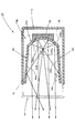
- FIG. 1 is a front view showing a two-wheeled vehicle headlamp 10 according to an embodiment of the present invention.
- 2 is a cross-sectional view taken along the line II-II in FIG. 3 is a cross-sectional view taken along line III-III in FIG.
- the direction indicated by X is the front of the lamp (“front” as a vehicle)
- the direction indicated by Y is the left direction of the lamp orthogonal to the forward direction of the lamp.
- the two-wheeled vehicle headlamp 10 is a horizontally long lamp.
- the two-wheeled vehicle headlamp 10 includes a lamp body 12 having an opening at the front end, and a transparent translucent cover 14 attached to the opening.
- a pair of left and right lamp units 20L and 20R are accommodated in a lamp chamber formed by the lamp body 12 and the translucent cover 14.
- the two-wheeled vehicle headlamp 10 forms a low-beam light distribution pattern as a two-wheeled vehicle light distribution pattern by irradiation light from both lamp units 20L and 20R.
- the left lamp unit 20L includes a light emitting element 22L arranged to the left and a reflector 24L arranged on the left side of the light emitting element 22L.
- the right lamp unit 20R includes a light emitting element 22R arranged to the right and a reflector 24R arranged on the right side of the light emitting element 22R.
- the structures of both lamp units 20L and 20R are symmetrical.
- the reflecting surfaces 24La and 24Ra of the reflectors 24L and 24R include a plurality of reflecting elements 24Ls and 24Rs.
- Each of the plurality of reflecting elements 24Ls, 24Rs reflects light from the light emitting elements 22L, 22R as parallel light slightly downward in the vertical direction and forward in the horizontal direction. Reflected as diffused light spreading on both sides.
- the light emitting elements 22L and 22R have rectangular light emitting surfaces 22La and 22Ra.
- the light emitting element 22L of the left lamp unit 20L is arranged with the light emitting surface 22La directed in the left direction orthogonal to the lamp front-rear direction and the upper edge of the light emitting surface 22La being horizontal.
- the light emitting element 22R of the right lamp unit 20R is arranged with the light emitting surface 22Ra directed in the right direction orthogonal to the lamp front-rear direction and the upper edge of the light emitting surface 22Ra being horizontal.
- the upper end edges of the light emitting surfaces 22La and 22Ra have a shape similar to at least a part of the horizontal cutoff line. In the present embodiment, the upper edges of the light emitting surfaces 22La and 22Ra are linear.
- Each of these light emitting elements 22L and 22R is supported by a light source support member 32 arranged along a vertical plane extending in the lamp front-rear direction.
- the light source support member 32 extends further to the rear than the reflectors 24L and 24R.
- the rear end portion of the light source support member 32 is fixed to the reflectors 24L and 24R via the holder 34.
- a light shielding plate 26 is disposed at the upper edge of the reflecting surfaces 24La and 24Ra of the reflectors 24L and 24R.
- the light shielding plate 26 shields light emitted upward from each of the light emitting elements 22L and 22R.
- the light shielding plate 26 is configured as a common member with respect to both the lamp units 20L and 20R. That is, the single light shielding plate 26 is provided so as to straddle the lamp unit 20L and the lamp unit 20R in the left-right direction.
- the light shielding plate 26 is formed integrally with both reflectors 24L and 24R.
- the light shielding plate 26 is formed to extend slightly upward toward the front, and extends slightly forward from the left and right front edges of the reflecting surfaces 24La and 24Ra.
- the lower surface 26a of the light shielding plate 26 is subjected to light reflection processing such as aluminum vapor deposition. Thereby, the light incident on the lower surface 26a of the light shielding plate 26 from each of the light emitting elements 22L and 22R is reflected downward and forward.
- a light shielding plate 28 is disposed at the lower edge of the reflecting surfaces 24La and 24Ra in the reflectors 24L and 24R.
- the light shielding plate 28 shields light emitted downward from each of the light emitting elements 22L and 22R.
- the light shielding plate 28 is configured as a common member with respect to both the lamp units 20L and 20R. That is, the single light shielding plate 28 is provided so as to straddle the lamp unit 20L and the lamp unit 20R in the left-right direction.
- the light shielding plate 26 is formed integrally with both reflectors 24L and 24R.
- the light shielding plate 28 is formed so as to extend slightly downward toward the front, and extends slightly forward from the left and right front edges of the reflecting surfaces 24La and 24Ra. Further, the upper surface 28a of the light shielding plate 28 is subjected to a light reflection process such as aluminum vapor deposition. This light reflection process is for enhancing the appearance of the lamp chamber.
- a plurality of diffuse reflection elements 28s extending in the front-rear direction of the lamp are formed on the upper surface 28a of the light shielding plate 28.
- Each of the plurality of diffuse reflection elements 28s reflects light incident on the upper surface 28a of the light shielding plate 28 from the respective light emitting elements 22L and 22R by largely diffusing upward and laterally.
- FIG. 4 is a perspective view showing a two-wheeler light distribution pattern formed on a virtual vertical screen arranged at a position 25 m ahead of the lamp by light irradiated forward from the two-wheeled vehicle headlamp 10.
- This light distribution pattern for motorcycles is a low beam light distribution pattern PL having a horizontal cutoff line CL at the upper end.
- the horizontal cut-off line CL of the low-beam light distribution pattern PL is located slightly below the horizontal line HH passing through HV, which is a vanishing point in the front direction of the lamp.
- the low beam light distribution pattern PL is composed of a pair of left and right basic light distribution patterns P0L and P0R and a pair of left and right additional light distribution patterns PaL and PaR.
- the left and right pair of basic light distribution patterns P0L and P0R are light distribution patterns that form the main part of the low beam light distribution pattern PL.
- the pair of left and right basic light distribution patterns P0L and P0R is formed at a position where the center in the left-right direction is near a vertical line VV passing through HV.
- the pair of left and right basic light distribution patterns P0L and P0R are formed slightly shifted from each other in the left-right direction. Then, a horizontal cut-off line CL of the low beam light distribution pattern PL is formed by these basic light distribution patterns P0L and P0R.
- the left basic light distribution pattern P0L is a light distribution pattern formed by light from the light emitting element 22L reflected by the reflector 24L of the left lamp unit 20L. Since the shape of the upper edge of the light emitting surface 22La of the light emitting element 22L is reflected by the reflector 24L and projected forward, the upper edge of the left basic light distribution pattern P0L formed by the light from the light emitting element 22L is flat. .
- the right basic light distribution pattern P0R is a light distribution pattern formed by light from the light emitting element 22R reflected by the reflector 24R of the right lamp unit 20R.
- the upper edge of the light emitting surface 22Ra of the light emitting element 22R is reflected by the reflector 24R and projected forward, the upper edge of the right basic light distribution pattern P0R formed by the light from the light emitting element 22R is flat. . Since the light emitting elements 22L and 22R are arranged so that the upper end edges of the linear light emitting surfaces 22La and 22Ra are horizontal, the upper ends of the low beam light distribution patterns PL formed by the left and right basic light distribution patterns P0L and P0R. The edge is a straight horizontal cut-off line CL.
- the pair of left and right additional light distribution patterns PaL and PaR are light distribution patterns for reinforcing the brightness of the lateral regions of both basic light distribution patterns P0L and P0R.
- the side regions are a region extending to the left and the left side of the basic light distribution pattern P0L, and a region extending to the right and the right side of the basic light distribution pattern P0R.
- the left additional light distribution pattern PaL is formed so as to partially overlap the left end portions of both basic light distribution patterns P0L and P0R.
- the additional light distribution pattern PaR on the right side is formed so as to partially overlap the right end portions of both basic light distribution patterns P0L and P0R.
- areas illuminated by the light from the light emitting elements 22L and 22R reflected by the reflectors 24L and 24R with an illuminance of a predetermined value or more are shown as basic light distribution patterns P0L and P0R.
- the outside is also illuminated by the light with an illuminance less than a predetermined value.
- the additional light distribution patterns PaL and PaR the illuminance of the side region including the region illuminated with the illuminance less than the predetermined value is increased.
- the left additional light distribution pattern PaL is a light distribution pattern formed by direct light emitted from the light emitting element 22L of the left lamp unit 20L toward the front side of the reflector 24L.
- the right additional light distribution pattern PaR is a light distribution pattern formed by direct light emitted from the light emitting element 22R of the right lamp unit 20R toward the front side of the reflector 24R.
- the luminous intensity distribution of the direct light from the light emitting element 22L arranged in the left direction has the highest luminous intensity at a position far away from the lamp front direction to the left direction.
- the left additional light distribution pattern PaL is formed around a position with the highest luminous intensity that is far away in the left direction from the front direction of the lamp.
- the luminous intensity distribution of the direct light from the light emitting element 22R arranged in the right direction has the highest luminous intensity at a position far away from the lamp front direction to the right direction.
- the additional light distribution pattern PaR on the right side is formed around a position with the highest luminous intensity that is far away from the lamp front direction to the right direction.
- each additional light distribution pattern PaL, PaR is formed as a light distribution pattern extending above the horizontal cutoff line CL.
- each of these additional light distribution patterns PaL and PaR is formed at positions separated from the HV position on both the left and right sides. For this reason, there is no possibility that glare will be given to the driver of the preceding vehicle, the driver of the oncoming vehicle, or the like due to the portion extending above the horizontal cut-off line CL.
- the direct light emitted at a large upward angle from the light emitting elements 22L and 22R of the lamp units 20L and 20R forward is blocked by the light blocking plate 26.
- the upward protrusion amount of each additional light distribution pattern PaL, PaR from the horizontal cut-off line CL is relatively small. Therefore, there is no possibility that glare is given to a pedestrian or the like by the additional light distribution patterns PaL and PaR.
- the light reaching the light shielding plate 26 is reflected downward on the lower surface 26a toward the front.
- the area below the horizontal cutoff line CL in each additional light distribution pattern PaL, PaR becomes brighter.
- the direct light that has been emitted downward from the light emitting elements 22L and 22R of the lamp units 20L and 20R and reached the light shielding plate 28 is reflected upward on the upper surface 28a.
- the direct light is largely diffused and reflected in the left-right direction by the plurality of diffuse reflection elements 28s formed on the upper surface 28a, so that there is no possibility of generating glare light.
- the light from the light emitting element 22L arranged in the left direction is reflected by the reflector 24L.
- the light from the light emitting element 22R arranged in the right direction is reflected by the reflector 24R.
- a light distribution pattern formed by the reflected light from both the reflectors 24L and 24R has a basic cut-off line CL at the upper end.
- Light distribution patterns P0L and P0R can be formed. Thereby, the light distribution pattern PL for low beams which has the horizontal cut-off line CL in the upper end part as a light distribution pattern for motorcycles can be formed.
- the left lamp unit 20L has an additional light distribution pattern PaL that reinforces the brightness of the side region of the basic light distribution pattern P0L by direct light emitted toward the front side of the reflector 24L from the light emitting element 22L arranged to the left.
- the right lamp unit 20R has an additional light distribution that reinforces the brightness of the side area of the basic light distribution pattern P0R by direct light emitted toward the front side of the reflector 24R from the light emitting element 22R arranged in the right direction.
- a pattern PaR is formed. Thereby, the wide area
- the low beam having a horizontal cut-off line CL at the upper end as the light distribution pattern for the two-wheeled vehicle.
- a light distribution pattern PL can be formed.
- the left additional light distribution pattern PaL is formed around a position that is far away from the front of the lamp in the left direction.
- the additional light distribution pattern PaR on the right side is formed around a position far away from the lamp front direction to the left direction. Therefore, there is no possibility that glare will be given to the driver of the preceding vehicle, the driver of the oncoming vehicle, etc. by these additional light distribution patterns PaL and PaR.
- a light shielding plate 26 that shields direct light emitted upward from the light emitting elements 22L and 22R forward is disposed at the upper edge of the reflecting surfaces 24La and 24Ra in the reflectors 24L and 24R. ing. For this reason, it can prevent giving glare to the pedestrian etc. in the road shoulder part of a vehicle front road surface by the direct light from each light emitting element 22L, 22R.
- the lower surface 26a of the light shielding plate 26 is subjected to a light reflection process. For this reason, the light shielded by the light shielding plate 26 can be positively used as light for irradiating the road surface ahead of the vehicle. Thereby, the light distribution pattern PL for low beams can be made more excellent in visibility.
- the pair of left and right lamp units 20L and 20R are arranged such that the light emitting elements 22L and 22R are back to back. For this reason, the lamp units 20L and 20R can be efficiently arranged in a narrow space.
- the example in which the light shielding plate 26 is formed so as to extend slightly upward toward the front has been described, but it may be formed to extend horizontally or slightly downward toward the front.
- the example in which the light shielding plates 26 and 28 are formed integrally with both the reflectors 24L and 24R has been described, but the light shielding plates 26 and 28 may be formed separately from both the reflectors 24L and 24R.
- the low beam light distribution pattern PL is formed as the motorcycle light distribution pattern
- a fog light distribution pattern or the like may be formed.
- the upper end edges of the light emitting surfaces 22La and 22Ra of the light emitting elements 22L and 22R are horizontally arranged and projected forward, thereby forming the horizontal cut-off line CL of the low beam light distribution pattern PL.
- the method of forming the horizontal cut-off line CL is not limited to this example.
- the horizontal cut-off line CL may be formed by devising the shape of the reflector or arranging a shade that blocks a part of the light.
- FIG. 5 is a view similar to FIG. 1, showing a two-wheeled vehicle headlamp 110 according to this modification.
- the basic configuration of the two-wheeled vehicle headlamp 110 is the same as that of the above embodiment, but in this modification, a pair of left and right lamp units 20L, 20R in the above embodiment.
- each lamp unit 120L located on the left side includes a light emitting element 122L arranged to the right and a reflector 124L arranged on the right side of the light emitting element 122L.
- Each lamp unit 120R located on the right side includes a light emitting element 122R arranged to the left and a reflector 124R arranged on the left side of the light emitting element 122R.
- the light shielding plates 126L and 126R having the same configuration as the left and right halves of the light shielding plate 26 of the above-described embodiment are respectively disposed at the upper edge portions of the uppermost lamp units 120L and 120R.
- light shielding plates 128L and 128R having the same configuration as the left and right halves of the light shielding plate 28 of the above-described embodiment are arranged at the lower end edges of the lowermost lamp units 120L and 120R, respectively.
- the light shielding plates 140L and 140R having the functions of the left and right halves of the light shielding plates 26 and 28 are respectively disposed. That is, the light reflection processing by aluminum deposition or the like is performed on the upper surfaces 140La1 and 140Ra1 and the lower surfaces 140La2 and 140Ra2 of the respective light shielding plates 140L and 140R.
- a plurality of diffuse reflection elements 140Ls and 140Rs extending in the front-rear direction of the lamp are formed on the upper surfaces 140La1 and 140Ra1 of the light shielding plates 140L and 140R, respectively.
- a pair of left and right light source support members 132L and 132R are arranged so as to extend from the upper end to the lower end of the three sets of lamp units 120L and 120R at the left and right ends of the lamp chamber.
- the left light source support member 132L supports the light emitting elements 122L of the three left lamp units 120L.
- the right light source support member 132R supports the light emitting elements 122R of the three right lamp units 120R.
- the low beam light distribution pattern similar to the low beam light distribution pattern PL shown in FIG. 4 is formed by the light irradiated forward from the two-wheeled vehicle headlamp 110.
- the brightness of the low beam light distribution pattern formed by the two-wheeled vehicle headlamp 110 of the present modification is three times the brightness of the low beam light distribution pattern PL of the two-wheeled vehicle headlamp 10 of the above embodiment.
- the low beam light distribution pattern PL can be made brighter and more excellent in visibility.
- the three sets of lamp units 120L and 120R are arranged in three upper and lower stages, the lateral width of the lamp body 112 and the translucent cover 114 that accommodate them is not increased.
- the two-wheeled vehicle headlamp suitable for the vehicle structure of a two-wheeled vehicle can be provided.
- a two-wheeled vehicle headlamp that has a horizontal cut-off line at the upper end as a light distribution pattern for a motorcycle and can form a light distribution pattern with excellent visibility.
Landscapes
- Engineering & Computer Science (AREA)
- General Engineering & Computer Science (AREA)
- Non-Portable Lighting Devices Or Systems Thereof (AREA)
Abstract
1対の灯具ユニットを備えた二輪車用前照灯において、二輪車用配光パターンとして上端部に水平カットオフラインを有し、視認性に優れた配光パターンを形成可能とする。 左右1対の灯具ユニット20L、20Rを備えた構成とする。そして、各灯具ユニット20L、20Rの発光素子22L、22Rにおける発光面22La、24Raの端縁形状を利用して、各リフレクタ24L、24Rからの反射光によって形成される配光パターンを、上端部に水平カットオフラインを有する基本配光パターンとして形成するようにする。その上で、各発光素子22L、22Rから各リフレクタ24L、24Rの前方側へ向けて出射した直射光により、基本配光パターンの側方領域の明るさを補強する付加配光パターンを形成するようにする。
Description
本願発明は、複数の灯具ユニットを備えた二輪車用前照灯に関する。
従来より、複数の灯具ユニットからの照射光により二輪車用配光パターンを形成する二輪車用前照灯が知られている。
例えば特許文献1には、上下1対の灯具ユニットを備えた二輪車用前照灯が記載されている。この二輪車用前照灯において、上側の灯具ユニットは、上向きに配置された発光素子とその上方側に配置されたリフレクタとを備えている。下側の灯具ユニットは、下向きに配置された発光素子とその下方側に配置されたリフレクタとを備えている。
特許文献1に記載された二輪車用前照灯において、1対の灯具ユニットは、その発光素子を互いに背中合わせにした状態で配置されている。これにより、両灯具ユニットを狭い空間に効率良く配置している。
しかしながら、特許文献1に記載された二輪車用前照灯のように、1対の灯具ユニットが上下に配置された構成では、二輪車用配光パターンとして上端部に水平カットオフラインを有する配光パターンを形成することは困難である。また、各灯具ユニットにおいて発光素子からリフレクタの前方側へ向けて出射する直射光を、配光パターンの視認性を高めるために有効に利用することも困難である。
本願発明は、このような事情に鑑みてなされたものであって、少なくとも1対の灯具ユニットを備えた二輪車用前照灯において、二輪車用配光パターンとして上端部に水平カットオフラインを有し、視認性に優れた配光パターンを形成することができる二輪車用前照灯を提供することを目的とする。
本願発明に係る二輪車用前照灯は、
複数の灯具ユニットからの照射光により二輪車用配光パターンを形成する二輪車用前照灯において、
前記複数の灯具ユニットとして左右1対の灯具ユニットを備えており、
前記左右1対の灯具ユニットのうち、
一方の灯具ユニットが、左向きに配置された発光素子と、この発光素子の左側に配置されたリフレクタとを備え、
他方の灯具ユニットが、右向きに配置された発光素子と、この発光素子の右側に配置されたリフレクタとを備え、
前記各リフレクタで反射した前記各発光素子からの光により、上端部に水平カットオフラインを有する基本配光パターンを形成するとともに、前記各発光素子から前記各リフレクタの前方側へ向けて出射した直射光により、前記基本配光パターンの側方領域の明るさを補強する付加配光パターンを形成する。
複数の灯具ユニットからの照射光により二輪車用配光パターンを形成する二輪車用前照灯において、
前記複数の灯具ユニットとして左右1対の灯具ユニットを備えており、
前記左右1対の灯具ユニットのうち、
一方の灯具ユニットが、左向きに配置された発光素子と、この発光素子の左側に配置されたリフレクタとを備え、
他方の灯具ユニットが、右向きに配置された発光素子と、この発光素子の右側に配置されたリフレクタとを備え、
前記各リフレクタで反射した前記各発光素子からの光により、上端部に水平カットオフラインを有する基本配光パターンを形成するとともに、前記各発光素子から前記各リフレクタの前方側へ向けて出射した直射光により、前記基本配光パターンの側方領域の明るさを補強する付加配光パターンを形成する。
発光素子の種類は特に限定されるものではなく、例えばLED(Light Emitting Diode)やLD(Laser Diode)、有機EL(Electro Luminescence)素子等が採用可能である。
基本配光パターンは、上端部に水平カットオフラインを有する配光パターンであれば、その具体的な形状は特に限定されるものではない。
付加配光パターンは、基本配光パターンの側方領域の明るさを補強する配光パターンであれば、その具体的な形状や形成位置等は特に限定されるものではない。
本願発明に係る二輪車用前照灯は、一方の灯具ユニットにおいて左向きに配置された発光素子からの光をリフレクタで反射させ、また、他方の灯具ユニットにおいて右向きに配置された発光素子からの光をリフレクタで反射させる。このため、各発光素子における発光面の端縁形状を利用して、上端部に水平カットオフラインを有する基本配光パターンを形成することができる。
一方の灯具ユニットは、左向きに配置された発光素子からリフレクタの前方側へ向けて出射した直射光により、基本配光パターンの左側に、側方領域の明るさを補強する付加配光パターンを形成することができる。他方の灯具ユニットは、右向きに配置された発光素子からリフレクタの前方側へ向けて出射した直射光により、基本配光パターンの右側に、側方領域の明るさを補強する付加配光パターンを形成することができる。これにより、視認性に優れた二輪車用配光パターンを形成することができる。
このように本願発明によれば、1対の灯具ユニットを備えた二輪車用前照灯において、二輪車用配光パターンとして上端部に水平カットオフラインを有し、視認性に優れた配光パターンを形成することができる。
以下、図面を用いて、本願発明の実施の形態について説明する。
図1は、本願発明の一実施形態に係る二輪車用前照灯10を示す正面図である。図2は図1のII-II線断面図である。図3は図1のIII-III線断面図である。図2において、Xで示す方向が灯具の前方(車両としても「前方」)であり、Yで示す方向が灯具の前方方向と直交する灯具の左方向である。
図1から図3に示すように、この二輪車用前照灯10は、横長の灯具である。二輪車用前照灯10は、前端に開口部を有するランプボディ12と、その開口部に取り付けられた素通し状の透光カバー14とを備えている。ランプボディ12と透光カバー14とにより形成される灯室内に、左右1対の灯具ユニット20L、20Rが収容されている。二輪車用前照灯10は、両灯具ユニット20L、20Rからの照射光により、二輪車用配光パターンとしてロービーム用配光パターンを形成する。
左側の灯具ユニット20Lは、左向きに配置された発光素子22Lと、この発光素子22Lの左側に配置されたリフレクタ24Lとを備えている。右側の灯具ユニット20Rは、右向きに配置された発光素子22Rと、この発光素子22Rの右側に配置されたリフレクタ24Rとを備えている。両灯具ユニット20L、20Rの構造は左右対称とされている。
これら各リフレクタ24L、24Rの反射面24La、24Raは、複数の反射素子24Ls、24Rsを備えている。これら複数の反射素子24Ls、24Rsの各々は、各発光素子22L、22Rからの光を、上下方向に関しては前方へ向けてやや下向きの平行光として反射させ、かつ、水平方向に関しては前方へ向けて左右両側に広がる拡散光として反射させる。
各発光素子22L、22Rは、矩形状の発光面22La、22Raを有している。左側の灯具ユニット20Lの発光素子22Lは、その発光面22Laを灯具前後方向と直交する左方向に向け、かつ、その発光面22Laの上端縁を水平にした状態で配置されている。右側の灯具ユニット20Rの発光素子22Rは、その発光面22Raを灯具前後方向と直交する右方向に向け、かつ、その発光面22Raの上端縁を水平にした状態で配置されている。発光面22La,22Raの上端縁は水平カットオフラインの少なくとも一部に相似の形状とされている。本実施形態においては発光面22La,22Raの上端縁は直線状とされている。
これら各発光素子22L、22Rは、灯具前後方向に延びる鉛直面に沿って配置された光源支持部材32に支持されている。この光源支持部材32は、両リフレクタ24L、24Rよりも後方まで延びている。光源支持部材32の後端部は、ホルダ34を介して両リフレクタ24L、24Rに固定されている。
各リフレクタ24L、24Rの反射面24La、24Raの上端縁部には、遮光板26が配置されている。遮光板26は、各発光素子22L、22Rから前方へ向けて上向きに出射する光を遮光する。この遮光板26は、両灯具ユニット20L、20Rに関して共通の部材として構成されている。つまり単一の遮光板26は、左右方向に関して灯具ユニット20Lと灯具ユニット20Rに跨るように設けられている。この遮光板26は、両リフレクタ24L、24Rと一体的に形成されている。
この遮光板26は、前方へ向けてやや上向きに延びるように形成されており、各反射面24La、24Raの左右前端縁よりもやや前方まで延びている。また、この遮光板26の下面26aには、アルミ蒸着等による光反射処理が施されている。これにより、各発光素子22L、22Rから遮光板26の下面26aに入射した光が前方へ向けて下向きに反射される。
一方、各リフレクタ24L、24Rにおける反射面24La、24Raの下端縁部には、遮光板28が配置されている。遮光板28は各発光素子22L、22Rから前方へ向けて下向きに出射する光を遮光する。この遮光板28は、両灯具ユニット20L、20Rに関して共通の部材として構成されている。つまり単一の遮光板28は、左右方向に関して灯具ユニット20Lと灯具ユニット20Rに跨るように設けられている。この遮光板26は、両リフレクタ24L、24Rと一体的に形成されている。
この遮光板28は、前方へ向けてやや下向きに延びるように形成されており、各反射面24La、24Raの左右前端縁よりもやや前方まで延びている。また、この遮光板28の上面28aには、アルミ蒸着等による光反射処理が施されている。この光反射処理は、灯室内の見映えを高めるためのものである。
この遮光板28の上面28aには、灯具前後方向に延びる複数の拡散反射素子28sが形成されている。そして、これら複数の拡散反射素子28sの各々は、各発光素子22L、22Rから遮光板28の上面28aに入射した光を前方へ向けて上向きに、かつ、左右方向に大きく拡散させて反射させる。
図4は、二輪車用前照灯10から前方へ照射される光により灯具前方25mの位置に配置された仮想鉛直スクリーン上に形成される二輪車用配光パターンを透視的に示す図である。
この二輪車用配光パターンは、上端部に水平カットオフラインCLを有するロービーム用配光パターンPLである。ロービーム用配光パターンPLの水平カットオフラインCLは、灯具正面方向の消点であるH-Vを通る水平線H-Hよりもやや下方に位置している。
このロービーム用配光パターンPLは、左右1対の基本配光パターンP0L、P0Rと左右1対の付加配光パターンPaL、PaRとで構成されている。
左右1対の基本配光パターンP0L、P0Rは、ロービーム用配光パターンPLの主要部を形成する配光パターンである。左右1対の基本配光パターンP0L、P0Rは、その左右方向の中心がH-Vを通る鉛直線V-Vの近くとなる位置に形成されている。また左右1対の基本配光パターンP0L、P0Rは、左右方向に互いに僅かにずれて形成されている。そして、これら基本配光パターンP0L、P0Rによってロービーム用配光パターンPLの水平カットオフラインCLが形成される。
左側の基本配光パターンP0Lは、左側の灯具ユニット20Lのリフレクタ24Lで反射した発光素子22Lからの光により形成される配光パターンである。発光素子22Lの発光面22Laの上端縁の形状がリフレクタ24Lで反射されて前方に投影されるため、発光素子22Lからの光により形成される左側の基本配光パターンP0Lの上端縁は平坦となる。
右側の基本配光パターンP0Rは、右側の灯具ユニット20Rのリフレクタ24Rで反射した発光素子22Rからの光により形成される配光パターンである。発光素子22Rの発光面22Raの上端縁の形状がリフレクタ24Rで反射されて前方に投影されるため、発光素子22Rからの光により形成される右側の基本配光パターンP0Rの上端縁は平坦となる。
直線状の発光面22La,22Raの上端縁が水平となるように発光素子22L,22Rが配置されているため、左右の基本配光パターンP0L,P0Rにより形成されるロービーム用配光パターンPLの上端縁は直線状の水平カットオフラインCLとなる。
右側の基本配光パターンP0Rは、右側の灯具ユニット20Rのリフレクタ24Rで反射した発光素子22Rからの光により形成される配光パターンである。発光素子22Rの発光面22Raの上端縁の形状がリフレクタ24Rで反射されて前方に投影されるため、発光素子22Rからの光により形成される右側の基本配光パターンP0Rの上端縁は平坦となる。
直線状の発光面22La,22Raの上端縁が水平となるように発光素子22L,22Rが配置されているため、左右の基本配光パターンP0L,P0Rにより形成されるロービーム用配光パターンPLの上端縁は直線状の水平カットオフラインCLとなる。
左右1対の付加配光パターンPaL、PaRは、両基本配光パターンP0L、P0Rの側方領域の明るさを補強するための配光パターンである。側方領域とは、基本配光パターンP0Lの左部分およびその左側に広がる領域、および基本配光パターンP0Rの右部分およびその右側に広がる領域である。左側の付加配光パターンPaLは、両基本配光パターンP0L、P0Rの左端部と部分的に重複するように形成されている。右側の付加配光パターンPaRは、両基本配光パターンP0L、P0Rの右端部と部分的に重複するように形成されている。
図4において、それぞれのリフレクタ24L,24Rで反射した発光素子22L,22Rからの光により所定値以上の照度で照らされる領域を基本配光パターンP0L,P0Rとして示しているが、図示した領域の左右の外側も該光によって所定値未満の照度で照らされている。付加配光パターンPaL、PaRが形成されることにより、この所定値未満の照度で照らされている領域を含む側方領域の照度が高められる。
図4において、それぞれのリフレクタ24L,24Rで反射した発光素子22L,22Rからの光により所定値以上の照度で照らされる領域を基本配光パターンP0L,P0Rとして示しているが、図示した領域の左右の外側も該光によって所定値未満の照度で照らされている。付加配光パターンPaL、PaRが形成されることにより、この所定値未満の照度で照らされている領域を含む側方領域の照度が高められる。
左側の付加配光パターンPaLは、左側の灯具ユニット20Lの発光素子22Lからそのリフレクタ24Lの前方側へ向けて出射した直射光により形成される配光パターンである。右側の付加配光パターンPaRは、右側の灯具ユニット20Rの発光素子22Rからそのリフレクタ24Rの前方側へ向けて出射した直射光により形成される配光パターンである。
左向きに配置された発光素子22Lからの直射光の光度分布は、灯具正面方向から左方向に大きく離れた位置において最も光度が高くなる。左側の付加配光パターンPaLは、灯具正面方向から左方向に大きく離れた最も光度の高い位置を中心にして形成されている。右向きに配置された発光素子22Rからの直射光の光度分布は、灯具正面方向から右方向に大きく離れた位置において最も光度が高くなる。右側の付加配光パターンPaRは、灯具正面方向から右方向に大きく離れた最も光度の高い位置を中心にして形成されている。
これら各付加配光パターンPaL、PaRを形成する各発光素子22L、22Rからの直射光は上向き光の成分を含む。このため、各付加配光パターンPaL、PaRは水平カットオフラインCLよりも上方まで拡がる配光パターンとして形成される。
ただし、これら各付加配光パターンPaL、PaRは、H-Vの位置から左右両側に離れた位置に形成される。このため、水平カットオフラインCLよりも上方まで拡がった部分によって前走車のドライバや対向車のドライバ等にグレアを与えてしまうおそれはない。
さらに、各灯具ユニット20L、20Rの発光素子22L、22Rから前方へ向けて大きい上向き角度で出射した直射光は、遮光板26により遮光される。このため各付加配光パターンPaL、PaRの水平カットオフラインCLからの上方突出量は比較的小さくなる。したがって、各付加配光パターンPaL、PaRによって歩行者等にグレアを与えてしまうおそれもない。
遮光板26に到達した光は、その下面26aにおいて前方へ向けて下向きに反射される。下面26aで下向きに反射された光により、各付加配光パターンPaL、PaRにおける水平カットオフラインCLよりも下方の領域がより明るくなる。
なお、各灯具ユニット20L、20Rの発光素子22L、22Rから前方へ向けて下向きに出射して遮光板28に到達した直射光は、その上面28aにおいて上向きに反射される。しかし、この上面28aに形成された複数の拡散反射素子28sにより該直射光は左右方向に大きく拡散して反射されるので、グレア光が発生するおそれはない。
次に、本実施形態の作用効果について説明する。
本実施形態に係る二輪車用前照灯によれば、左側の灯具ユニット20L(すなわち一方の灯具ユニット)において、左向きに配置された発光素子22Lからの光はリフレクタ24Lで反射される。また、右側の灯具ユニット20R(すなわち他方の灯具ユニット)において、右向きに配置された発光素子22Rからの光はリフレクタ24Rで反射される。各発光素子22L、22Rにおける発光面22La、24Raの端縁形状を利用することにより、両リフレクタ24L、24Rからの反射光によって形成される配光パターンを、上端部に水平カットオフラインCLを有する基本配光パターンP0L、P0Rとして形成することができる。これにより、二輪車用配光パターンとして上端部に水平カットオフラインCLを有するロービーム用配光パターンPLを形成することができる。
左側の灯具ユニット20Lは、左向きに配置された発光素子22Lからリフレクタ24Lの前方側へ向けて出射した直射光により、基本配光パターンP0Lの側方領域の明るさを補強する付加配光パターンPaLを形成する。また、右側の灯具ユニット20Rは、右向きに配置された発光素子22Rからリフレクタ24Rの前方側へ向けて出射した直射光により、基本配光パターンP0Rの側方領域の明るさを補強する付加配光パターンPaRを形成する。これにより、基本配光パターンP0L、P0Rの側方の広い領域が明るく照らされて、視認性に優れたロービーム用配光パターンPLが形成される。
このように本実施形態によれば、1対の灯具ユニット20L、20Rを備えた二輪車用前照灯10において、二輪車用配光パターンとして上端部に水平カットオフラインCLを有する視認性に優れたロービーム用配光パターンPLを形成することができる。
左側の付加配光パターンPaLは、灯具正面方向から左方向に大きく離れた位置を中心にして形成される。右側の付加配光パターンPaRは、灯具正面方向から左方向に大きく離れた位置を中心にして形成される。したがって、これら付加配光パターンPaL、PaRによって、前走車のドライバや対向車のドライバ等にグレアを与えてしまうおそれがない。
また本実施形態においては、各リフレクタ24L、24Rにおける反射面24La、24Raの上端縁部に、各発光素子22L、22Rから前方へ向けて上向きに出射する直射光を遮光する遮光板26が配置されている。このため各発光素子22L、22Rからの直射光によって車両前方路面の路肩部分にいる歩行者等にグレアを与えてしまうことを防止できる。
遮光板26の下面26aには光反射処理が施されている。このため遮光板26によって遮光された光を、車両前方路面を照射するための光として積極的に利用することができる。これにより、ロービーム用配光パターンPLを一層視認性に優れたものとすることができる。
また本実施形態に係る二輪車用前照灯10によれば、左右1対の灯具ユニット20L、20Rは、その発光素子22L、22Rが互いに背中合わせとなるように配置されている。このため、灯具ユニット20L、20Rを狭い空間に効率良く配置することができる。
上記実施形態においては、遮光板26が、前方へ向けてやや上向きに延びるように形成されている例を説明したが、前方へ向けて水平あるいはやや下向きに延びるように形成してもよい。
上記実施形態においては、遮光板26、28が、両リフレクタ24L、24Rと一体的に形成されている例を説明したが、両リフレクタ24L、24Rと別体で形成してもよい。
上記実施形態においては、二輪車用配光パターンとしてロービーム用配光パターンPLを形成する例を説明したが、フォグランプ用の配光パターン等を形成してもよい。
上記実施形態においては、発光素子22L,22Rの発光面22La,22Raの上端縁を水平に配置し、これを前方に投影することにより、ロービーム用配光パターンPLの水平カットオフラインCLを形成した例を説明したが、水平カットオフラインCLを形成する手法はこの例に限られない。例えばリフレクタの形状を工夫したり、あるいは光の一部を遮るシェードを配置することにより、水平カットオフラインCLを形成してもよい。
次に、本発明の変形例について説明する。
図5は、本変形例に係る二輪車用前照灯110を示す、図1と同様の図である。
同図に示すように、この二輪車用前照灯110の基本的な構成は上記実施形態の場合と同様であるが、本変形例においては、上記実施形態における左右1対の灯具ユニット20L、20Rと同様の構成を有する左右1対の灯具ユニット120L、120Rが上下3段に配置されている。
本変形例においては、左側に位置する各灯具ユニット120Lが、右向きに配置された発光素子122Lと、この発光素子122Lの右側に配置されたリフレクタ124Lとを備えている。また、右側に位置する各灯具ユニット120Rが、左向きに配置された発光素子122Rと、この発光素子122Rの左側に配置されたリフレクタ124Rとを備えている。
最上段の各灯具ユニット120L、120Rの上端縁部には、上記実施形態の遮光板26の左右半分と同様の構成を有する遮光板126L、126Rがそれぞれ配置されている。また、最下段の各灯具ユニット120L、120Rの下端縁部には、上記実施形態の遮光板28の左右半分と同様の構成を有する遮光板128L、128Rがそれぞれ配置されている。
最上段の各灯具ユニット120L、120Rと中段の各灯具ユニット120L、120Rとの間および中段の各灯具ユニット120L、120Rと最下段の各灯具ユニット120L、120Rとの間には、上記実施形態の遮光板26、28の左右半分の機能を兼ね備えた遮光板140L、140Rがそれぞれ配置されている。すなわち、これら各遮光板140L、140Rの上面140La1、140Ra1および下面140La2、140Ra2には、それぞれアルミ蒸着等による光反射処理が施されている。また、各遮光板140L、140Rのの上面140La1、140Ra1には灯具前後方向に延びる複数の拡散反射素子140Ls、140Rsがそれぞれ形成されている。
本変形例においては、左右1対の光源支持部材132L、132Rが、灯室内の左右両端縁部において3組の灯具ユニット120L、120Rの上端部から下端部まで延びるようにして配置されている。左側の光源支持部材132Lには、左側の3つの灯具ユニット120Lの発光素子122Lが支持されている。右側の光源支持部材132Rには、右側の3つの灯具ユニット120Rの発光素子122Rが支持されている。
本変形例においても、二輪車用前照灯110から前方へ照射される光により、図4に示すロービーム用配光パターンPLと同様のロービーム用配光パターンが形成される。本変形例の二輪車用前照灯110が形成するロービーム用配光パターンの明るさは、上記実施形態の二輪車用前照灯10のロービーム用配光パターンPLの明るさの3倍である。
本変形例の構成を採用した場合においても、上記実施形態と同様の作用効果を得ることができる。
しかも本変形例においては、3組の灯具ユニット120L、120Rを備えているので、ロービーム用配光パターンPLをより明るく視認性に優れたものとすることができる。
本変形例においては、3組の灯具ユニット120L、120Rが上下3段で配置されているので、これらを収容するランプボディ112および透光カバー114の横幅が大きくならない。二輪車の車両構造において、二輪車用前照灯を配置するためのスペースを左右方向に大きく確保することは容易ではないが、上下方向に関して大きく確保することが比較的容易である。このため本変形例によれば、二輪車の車両構造に適した二輪車用前照灯を提供することができる。
なお、上記実施形態およびその変形例において諸元として示した数値は一例にすぎず、これらを適宜異なる値に設定してもよいことはもちろんである。
また、本願発明は、上記実施形態およびその変形例に記載された構成に限定されるものではなく、これ以外の種々の変更を加えた構成が採用可能である。
本出願は、2012年10月24日出願の日本特許出願(特願2012-234418)に基づくものであり、その内容はここに参照として取り込まれる。
本願発明によれば、二輪車用配光パターンとして上端部に水平カットオフラインを有し、視認性に優れた配光パターンを形成することができる二輪車用前照灯を提供することができる。
10、110 二輪車用前照灯
12、112 ランプボディ
14、114 透光カバー
20L、20R、120L、120R 灯具ユニット
22L、22R、122L、122R 発光素子
22La、22Ra 発光面
24L、24R、124L、124R リフレクタ
24La、24Ra 反射面
24Ls、24Rs 反射素子
26、28、126L、126R、128L、128R、140L、140R 遮光板
26a、140La2、140Ra2 下面
28a、140La1、140Ra1 上面
28s、140Ls、140Rs 拡散反射素子
32、132L、132R 光源支持部材
34 ホルダ
CL 水平カットオフライン
PL ロービーム用配光パターン
PaL、PaR 付加配光パターン
P0L、P0R 基本配光パターン
12、112 ランプボディ
14、114 透光カバー
20L、20R、120L、120R 灯具ユニット
22L、22R、122L、122R 発光素子
22La、22Ra 発光面
24L、24R、124L、124R リフレクタ
24La、24Ra 反射面
24Ls、24Rs 反射素子
26、28、126L、126R、128L、128R、140L、140R 遮光板
26a、140La2、140Ra2 下面
28a、140La1、140Ra1 上面
28s、140Ls、140Rs 拡散反射素子
32、132L、132R 光源支持部材
34 ホルダ
CL 水平カットオフライン
PL ロービーム用配光パターン
PaL、PaR 付加配光パターン
P0L、P0R 基本配光パターン
Claims (5)
- 複数の灯具ユニットからの照射光により二輪車用配光パターンを形成する二輪車用前照灯において、
前記複数の灯具ユニットとして左右1対の灯具ユニットを備えており、
前記左右1対の前記灯具ユニットのうち、
一方の灯具ユニットは、左向きに配置された発光素子と、この発光素子の左側に配置されたリフレクタとを備え、
他方の灯具ユニットは、右向きに配置された発光素子と、この発光素子の右側に配置されたリフレクタとを備えており、
前記各リフレクタで反射した前記各発光素子からの光により、上端部に水平カットオフラインを有する基本配光パターンを形成し、前記各発光素子から前記各リフレクタの前方側へ向けて出射した直射光により、前記基本配光パターンの側方領域の明るさを補強する付加配光パターンを形成する二輪車用前照灯。 - 前記各リフレクタにおける反射面の上端縁部に、前記各発光素子から前方へ向けて上向きに出射する光を遮光する遮光板が配置されている請求項1に記載の二輪車用前照灯。
- 前記各遮光板の下面に光反射処理が施されている請求項2に記載の二輪車用前照灯。
- 前記一方の灯具ユニットが前記他方の灯具ユニットに対して左側に配置されている請求項1から請求項3のいずれか一項に記載の二輪車用前照灯。
- 前記各灯具ユニットが上下方向に複数個ずつ配置されている請求項1から請求項4のいずれか一項に記載の二輪車用前照灯。
Applications Claiming Priority (2)
| Application Number | Priority Date | Filing Date | Title |
|---|---|---|---|
| JP2012234418A JP5961091B2 (ja) | 2012-10-24 | 2012-10-24 | 二輪車用前照灯 |
| JP2012-234418 | 2012-10-24 |
Publications (1)
| Publication Number | Publication Date |
|---|---|
| WO2014065214A1 true WO2014065214A1 (ja) | 2014-05-01 |
Family
ID=50544594
Family Applications (1)
| Application Number | Title | Priority Date | Filing Date |
|---|---|---|---|
| PCT/JP2013/078342 Ceased WO2014065214A1 (ja) | 2012-10-24 | 2013-10-18 | 二輪車用前照灯 |
Country Status (2)
| Country | Link |
|---|---|
| JP (1) | JP5961091B2 (ja) |
| WO (1) | WO2014065214A1 (ja) |
Cited By (1)
| Publication number | Priority date | Publication date | Assignee | Title |
|---|---|---|---|---|
| CN109654448A (zh) * | 2019-02-28 | 2019-04-19 | 华域视觉科技(上海)有限公司 | 车灯反射面及其加工方法、车灯反射镜、车灯模组和汽车 |
Families Citing this family (1)
| Publication number | Priority date | Publication date | Assignee | Title |
|---|---|---|---|---|
| FR3022979A1 (fr) * | 2014-06-27 | 2016-01-01 | Valeo Vision | Systeme d'eclairage et/ou de signalisation pour vehicules automobiles |
Citations (4)
| Publication number | Priority date | Publication date | Assignee | Title |
|---|---|---|---|---|
| JP2008226706A (ja) * | 2007-03-14 | 2008-09-25 | Koito Mfg Co Ltd | 車両用灯具 |
| JP2010080212A (ja) * | 2008-09-25 | 2010-04-08 | Koito Mfg Co Ltd | 車両用灯具 |
| JP2012119219A (ja) * | 2010-12-02 | 2012-06-21 | Koito Mfg Co Ltd | 車両用前照灯 |
| WO2012120947A1 (ja) * | 2011-03-04 | 2012-09-13 | 本田技研工業株式会社 | 車両の灯火装置及び同装置の取付構造 |
Family Cites Families (1)
| Publication number | Priority date | Publication date | Assignee | Title |
|---|---|---|---|---|
| JP4782051B2 (ja) * | 2007-03-15 | 2011-09-28 | 株式会社小糸製作所 | 二輪車用前照灯 |
-
2012
- 2012-10-24 JP JP2012234418A patent/JP5961091B2/ja active Active
-
2013
- 2013-10-18 WO PCT/JP2013/078342 patent/WO2014065214A1/ja not_active Ceased
Patent Citations (4)
| Publication number | Priority date | Publication date | Assignee | Title |
|---|---|---|---|---|
| JP2008226706A (ja) * | 2007-03-14 | 2008-09-25 | Koito Mfg Co Ltd | 車両用灯具 |
| JP2010080212A (ja) * | 2008-09-25 | 2010-04-08 | Koito Mfg Co Ltd | 車両用灯具 |
| JP2012119219A (ja) * | 2010-12-02 | 2012-06-21 | Koito Mfg Co Ltd | 車両用前照灯 |
| WO2012120947A1 (ja) * | 2011-03-04 | 2012-09-13 | 本田技研工業株式会社 | 車両の灯火装置及び同装置の取付構造 |
Cited By (2)
| Publication number | Priority date | Publication date | Assignee | Title |
|---|---|---|---|---|
| CN109654448A (zh) * | 2019-02-28 | 2019-04-19 | 华域视觉科技(上海)有限公司 | 车灯反射面及其加工方法、车灯反射镜、车灯模组和汽车 |
| CN109654448B (zh) * | 2019-02-28 | 2021-11-23 | 华域视觉科技(上海)有限公司 | 车灯反射面及其加工方法、车灯反射镜、车灯模组和汽车 |
Also Published As
| Publication number | Publication date |
|---|---|
| JP5961091B2 (ja) | 2016-08-02 |
| JP2014086273A (ja) | 2014-05-12 |
Similar Documents
| Publication | Publication Date | Title |
|---|---|---|
| JP6052569B2 (ja) | 車両用灯具ユニット | |
| JP6430120B2 (ja) | 二輪車用前照灯 | |
| JP6235237B2 (ja) | 車両用灯具 | |
| JP5897913B2 (ja) | 灯具ユニット | |
| JP6030932B2 (ja) | 車両用前照灯 | |
| US20150103549A1 (en) | Vehicle lamp | |
| JP7269025B2 (ja) | 車両用灯具 | |
| JP6630112B2 (ja) | 車両用灯具 | |
| JP2011086580A (ja) | 車両用前照灯 | |
| JP5686240B2 (ja) | 車両用灯具 | |
| JP5381351B2 (ja) | 車両用灯具 | |
| JP6264847B2 (ja) | 車両用灯具 | |
| JP7406357B2 (ja) | 車両用灯具 | |
| JP4234074B2 (ja) | 車両用照明灯具 | |
| JP6459305B2 (ja) | 車両用前照灯 | |
| WO2023074545A1 (ja) | 車両用灯具 | |
| JP5961091B2 (ja) | 二輪車用前照灯 | |
| JP6059599B2 (ja) | 車両用灯具 | |
| JP2022144102A (ja) | 車両用灯具 | |
| JP2018045838A (ja) | 発光モジュール及び車両用灯具 | |
| JP5418758B2 (ja) | 二輪車用前照灯 | |
| JP6464678B2 (ja) | 車両用前照灯 | |
| JP2015002128A (ja) | 車両用灯具 | |
| WO2023063137A1 (ja) | 車両用灯具 | |
| JP5478227B2 (ja) | 車両用照明灯具 |
Legal Events
| Date | Code | Title | Description |
|---|---|---|---|
| 121 | Ep: the epo has been informed by wipo that ep was designated in this application |
Ref document number: 13849455 Country of ref document: EP Kind code of ref document: A1 |
|
| NENP | Non-entry into the national phase |
Ref country code: DE |
|
| 122 | Ep: pct application non-entry in european phase |
Ref document number: 13849455 Country of ref document: EP Kind code of ref document: A1 |