WO2014064758A1 - 車両および車両用制御方法 - Google Patents
車両および車両用制御方法 Download PDFInfo
- Publication number
- WO2014064758A1 WO2014064758A1 PCT/JP2012/077291 JP2012077291W WO2014064758A1 WO 2014064758 A1 WO2014064758 A1 WO 2014064758A1 JP 2012077291 W JP2012077291 W JP 2012077291W WO 2014064758 A1 WO2014064758 A1 WO 2014064758A1
- Authority
- WO
- WIPO (PCT)
- Prior art keywords
- catalyst
- control
- vehicle
- ehc
- temperature
- Prior art date
- Legal status (The legal status is an assumption and is not a legal conclusion. Google has not performed a legal analysis and makes no representation as to the accuracy of the status listed.)
- Ceased
Links
Images



Classifications
-
- F—MECHANICAL ENGINEERING; LIGHTING; HEATING; WEAPONS; BLASTING
- F01—MACHINES OR ENGINES IN GENERAL; ENGINE PLANTS IN GENERAL; STEAM ENGINES
- F01N—GAS-FLOW SILENCERS OR EXHAUST APPARATUS FOR MACHINES OR ENGINES IN GENERAL; GAS-FLOW SILENCERS OR EXHAUST APPARATUS FOR INTERNAL-COMBUSTION ENGINES
- F01N3/00—Exhaust or silencing apparatus having means for purifying, rendering innocuous, or otherwise treating exhaust
- F01N3/08—Exhaust or silencing apparatus having means for purifying, rendering innocuous, or otherwise treating exhaust for rendering innocuous
- F01N3/10—Exhaust or silencing apparatus having means for purifying, rendering innocuous, or otherwise treating exhaust for rendering innocuous by thermal or catalytic conversion of noxious components of exhaust
- F01N3/18—Exhaust or silencing apparatus having means for purifying, rendering innocuous, or otherwise treating exhaust for rendering innocuous by thermal or catalytic conversion of noxious components of exhaust characterised by methods of operation; Control
- F01N3/20—Exhaust or silencing apparatus having means for purifying, rendering innocuous, or otherwise treating exhaust for rendering innocuous by thermal or catalytic conversion of noxious components of exhaust characterised by methods of operation; Control specially adapted for catalytic conversion
- F01N3/2006—Periodically heating or cooling catalytic reactors, e.g. at cold starting or overheating
- F01N3/2013—Periodically heating or cooling catalytic reactors, e.g. at cold starting or overheating using electric or magnetic heating means
-
- F—MECHANICAL ENGINEERING; LIGHTING; HEATING; WEAPONS; BLASTING
- F01—MACHINES OR ENGINES IN GENERAL; ENGINE PLANTS IN GENERAL; STEAM ENGINES
- F01N—GAS-FLOW SILENCERS OR EXHAUST APPARATUS FOR MACHINES OR ENGINES IN GENERAL; GAS-FLOW SILENCERS OR EXHAUST APPARATUS FOR INTERNAL-COMBUSTION ENGINES
- F01N3/00—Exhaust or silencing apparatus having means for purifying, rendering innocuous, or otherwise treating exhaust
- F01N3/08—Exhaust or silencing apparatus having means for purifying, rendering innocuous, or otherwise treating exhaust for rendering innocuous
- F01N3/10—Exhaust or silencing apparatus having means for purifying, rendering innocuous, or otherwise treating exhaust for rendering innocuous by thermal or catalytic conversion of noxious components of exhaust
- F01N3/18—Exhaust or silencing apparatus having means for purifying, rendering innocuous, or otherwise treating exhaust for rendering innocuous by thermal or catalytic conversion of noxious components of exhaust characterised by methods of operation; Control
- F01N3/20—Exhaust or silencing apparatus having means for purifying, rendering innocuous, or otherwise treating exhaust for rendering innocuous by thermal or catalytic conversion of noxious components of exhaust characterised by methods of operation; Control specially adapted for catalytic conversion
- F01N3/2006—Periodically heating or cooling catalytic reactors, e.g. at cold starting or overheating
- F01N3/2013—Periodically heating or cooling catalytic reactors, e.g. at cold starting or overheating using electric or magnetic heating means
- F01N3/2026—Periodically heating or cooling catalytic reactors, e.g. at cold starting or overheating using electric or magnetic heating means directly electrifying the catalyst substrate, i.e. heating the electrically conductive catalyst substrate by joule effect
-
- B—PERFORMING OPERATIONS; TRANSPORTING
- B60—VEHICLES IN GENERAL
- B60W—CONJOINT CONTROL OF VEHICLE SUB-UNITS OF DIFFERENT TYPE OR DIFFERENT FUNCTION; CONTROL SYSTEMS SPECIALLY ADAPTED FOR HYBRID VEHICLES; ROAD VEHICLE DRIVE CONTROL SYSTEMS FOR PURPOSES NOT RELATED TO THE CONTROL OF A PARTICULAR SUB-UNIT
- B60W10/00—Conjoint control of vehicle sub-units of different type or different function
- B60W10/30—Conjoint control of vehicle sub-units of different type or different function including control of auxiliary equipment, e.g. air-conditioning compressors or oil pumps
-
- F—MECHANICAL ENGINEERING; LIGHTING; HEATING; WEAPONS; BLASTING
- F01—MACHINES OR ENGINES IN GENERAL; ENGINE PLANTS IN GENERAL; STEAM ENGINES
- F01N—GAS-FLOW SILENCERS OR EXHAUST APPARATUS FOR MACHINES OR ENGINES IN GENERAL; GAS-FLOW SILENCERS OR EXHAUST APPARATUS FOR INTERNAL-COMBUSTION ENGINES
- F01N3/00—Exhaust or silencing apparatus having means for purifying, rendering innocuous, or otherwise treating exhaust
- F01N3/08—Exhaust or silencing apparatus having means for purifying, rendering innocuous, or otherwise treating exhaust for rendering innocuous
- F01N3/10—Exhaust or silencing apparatus having means for purifying, rendering innocuous, or otherwise treating exhaust for rendering innocuous by thermal or catalytic conversion of noxious components of exhaust
- F01N3/18—Exhaust or silencing apparatus having means for purifying, rendering innocuous, or otherwise treating exhaust for rendering innocuous by thermal or catalytic conversion of noxious components of exhaust characterised by methods of operation; Control
- F01N3/20—Exhaust or silencing apparatus having means for purifying, rendering innocuous, or otherwise treating exhaust for rendering innocuous by thermal or catalytic conversion of noxious components of exhaust characterised by methods of operation; Control specially adapted for catalytic conversion
-
- F—MECHANICAL ENGINEERING; LIGHTING; HEATING; WEAPONS; BLASTING
- F01—MACHINES OR ENGINES IN GENERAL; ENGINE PLANTS IN GENERAL; STEAM ENGINES
- F01N—GAS-FLOW SILENCERS OR EXHAUST APPARATUS FOR MACHINES OR ENGINES IN GENERAL; GAS-FLOW SILENCERS OR EXHAUST APPARATUS FOR INTERNAL-COMBUSTION ENGINES
- F01N9/00—Electrical control of exhaust gas treating apparatus
-
- F—MECHANICAL ENGINEERING; LIGHTING; HEATING; WEAPONS; BLASTING
- F01—MACHINES OR ENGINES IN GENERAL; ENGINE PLANTS IN GENERAL; STEAM ENGINES
- F01N—GAS-FLOW SILENCERS OR EXHAUST APPARATUS FOR MACHINES OR ENGINES IN GENERAL; GAS-FLOW SILENCERS OR EXHAUST APPARATUS FOR INTERNAL-COMBUSTION ENGINES
- F01N2900/00—Details of electrical control or of the monitoring of the exhaust gas treating apparatus
- F01N2900/06—Parameters used for exhaust control or diagnosing
- F01N2900/16—Parameters used for exhaust control or diagnosing said parameters being related to the exhaust apparatus, e.g. particulate filter or catalyst
- F01N2900/1602—Temperature of exhaust gas apparatus
-
- F—MECHANICAL ENGINEERING; LIGHTING; HEATING; WEAPONS; BLASTING
- F01—MACHINES OR ENGINES IN GENERAL; ENGINE PLANTS IN GENERAL; STEAM ENGINES
- F01N—GAS-FLOW SILENCERS OR EXHAUST APPARATUS FOR MACHINES OR ENGINES IN GENERAL; GAS-FLOW SILENCERS OR EXHAUST APPARATUS FOR INTERNAL-COMBUSTION ENGINES
- F01N2900/00—Details of electrical control or of the monitoring of the exhaust gas treating apparatus
- F01N2900/06—Parameters used for exhaust control or diagnosing
- F01N2900/16—Parameters used for exhaust control or diagnosing said parameters being related to the exhaust apparatus, e.g. particulate filter or catalyst
- F01N2900/1628—Moisture amount in exhaust apparatus
-
- Y—GENERAL TAGGING OF NEW TECHNOLOGICAL DEVELOPMENTS; GENERAL TAGGING OF CROSS-SECTIONAL TECHNOLOGIES SPANNING OVER SEVERAL SECTIONS OF THE IPC; TECHNICAL SUBJECTS COVERED BY FORMER USPC CROSS-REFERENCE ART COLLECTIONS [XRACs] AND DIGESTS
- Y02—TECHNOLOGIES OR APPLICATIONS FOR MITIGATION OR ADAPTATION AGAINST CLIMATE CHANGE
- Y02A—TECHNOLOGIES FOR ADAPTATION TO CLIMATE CHANGE
- Y02A50/00—TECHNOLOGIES FOR ADAPTATION TO CLIMATE CHANGE in human health protection, e.g. against extreme weather
- Y02A50/20—Air quality improvement or preservation, e.g. vehicle emission control or emission reduction by using catalytic converters
-
- Y—GENERAL TAGGING OF NEW TECHNOLOGICAL DEVELOPMENTS; GENERAL TAGGING OF CROSS-SECTIONAL TECHNOLOGIES SPANNING OVER SEVERAL SECTIONS OF THE IPC; TECHNICAL SUBJECTS COVERED BY FORMER USPC CROSS-REFERENCE ART COLLECTIONS [XRACs] AND DIGESTS
- Y02—TECHNOLOGIES OR APPLICATIONS FOR MITIGATION OR ADAPTATION AGAINST CLIMATE CHANGE
- Y02T—CLIMATE CHANGE MITIGATION TECHNOLOGIES RELATED TO TRANSPORTATION
- Y02T10/00—Road transport of goods or passengers
- Y02T10/10—Internal combustion engine [ICE] based vehicles
- Y02T10/12—Improving ICE efficiencies
-
- Y—GENERAL TAGGING OF NEW TECHNOLOGICAL DEVELOPMENTS; GENERAL TAGGING OF CROSS-SECTIONAL TECHNOLOGIES SPANNING OVER SEVERAL SECTIONS OF THE IPC; TECHNICAL SUBJECTS COVERED BY FORMER USPC CROSS-REFERENCE ART COLLECTIONS [XRACs] AND DIGESTS
- Y02—TECHNOLOGIES OR APPLICATIONS FOR MITIGATION OR ADAPTATION AGAINST CLIMATE CHANGE
- Y02T—CLIMATE CHANGE MITIGATION TECHNOLOGIES RELATED TO TRANSPORTATION
- Y02T10/00—Road transport of goods or passengers
- Y02T10/10—Internal combustion engine [ICE] based vehicles
- Y02T10/40—Engine management systems
Definitions
- the present invention relates to a technique for suppressing the occurrence of electric leakage in a catalyst device heated using electric power.
- Patent Document 1 environmental conditions defined by the outside air temperature, humidity, and atmospheric pressure are determined in advance in order to suppress the occurrence of leakage during energization of EHC (Electric Heating Catalyst).
- EHC Electro Heating Catalyst
- a technique is disclosed in which energization of EHC is started in a case where the dew condensation occurs, and moisture or condensed water in the exhaust gas is evaporated.
- An object of the present invention is to provide a vehicle and a vehicle control method that suppress the occurrence of electric leakage in a catalyst device that is heated using electric power.
- a vehicle includes an engine, a power storage device that is electrically insulated from the vehicle body, a catalyst device that is heated using electric power of the power storage device, and purifies exhaust gas of the engine, and heating of the catalyst device And a control device for executing the control.
- the catalyst device is configured to be electrically insulated from the vehicle body.
- the control device executes the heating control when the insulation state between the catalyst device and the vehicle body is not maintained.
- the vehicle further includes a detection device that detects a resistance value between the catalyst device and the vehicle body.
- the control device executes the heating control of the catalyst device when the resistance value is smaller than the threshold value.
- control device heats the catalyst device until the catalyst temperature reaches a temperature that oxidizes the soot between the catalyst device and the exhaust passage of the engine. Execute.
- control device vaporizes the catalyst device until the catalyst temperature reaches a first temperature at which moisture between the catalyst device and the exhaust passage of the engine evaporates. Execute control.
- the control device heats the catalyst device until the catalyst temperature reaches a second temperature that oxidizes the soot between the catalyst device and the exhaust passage.
- Execute baking control is a temperature higher than the first temperature.
- control device raises the temperature of the catalyst device by supplying electric power to the catalyst device.
- the vehicle further includes a rotating electrical machine that receives the supply of electric power from the power storage device and causes the vehicle to travel.
- a vehicle control method includes an engine, a power storage device that is electrically insulated from the vehicle body, and a catalyst device that is heated using the power of the power storage device to purify the exhaust gas of the engine. It is the control method for vehicles used for vehicles which include.
- the catalyst device is configured to be electrically insulated from the vehicle body.
- the vehicle control method includes a step of determining whether or not the insulation state between the catalyst device and the vehicle body is maintained, and heating the catalyst device when the insulation state between the catalyst device and the vehicle body is not maintained. Performing control.
- the catalyst device since the catalyst device is heated by executing the heating control when the insulation state between the catalyst device and the vehicle body is not maintained, the moisture between the exhaust passage and the catalyst device is evaporated, It can oxidize firewood. Thereby, the insulation state between the catalyst device and the vehicle body can be recovered. Therefore, it is possible to suppress the occurrence of electric leakage between the catalyst device and the vehicle body. Therefore, it is possible to provide a vehicle and a vehicle control method that suppress the occurrence of electric leakage in the catalyst device that is heated using electric power.
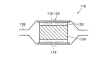
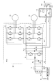
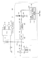
- FIG. 1 is an overall block diagram of a vehicle according to an embodiment. It is a figure which shows the structure of EHC. It is a circuit block diagram of 1st MG, 2nd MG, PCU, a battery, and EHC. It is a figure which shows the structure of a leak detection apparatus. It is a functional block diagram of ECU mounted in the vehicle which concerns on this Embodiment. It is a flowchart of the program run by ECU mounted in the vehicle which concerns on this Embodiment.
- the vehicle 1 includes a vehicle body 3, an engine 10, a drive shaft 16, a first motor generator (hereinafter referred to as a first MG) 20, a second motor generator (hereinafter referred to as a second MG) 30,
- the dividing device 40, the speed reducer 58, the PCU (Power Control Unit) 60, the battery 70, the DC / DC converter 71, the auxiliary battery 72, the drive wheel 80, and the ECU (Electronic Control Unit) 200 are provided. Including.
- the vehicle 1 travels by driving force output from at least one of the engine 10 and the second MG 30.
- the power generated by the engine 10 is divided into two paths by the power split device 40.
- One of the two routes is a route transmitted to the drive wheel 80 via the speed reducer 58, and the other route is a route transmitted to the first MG 20.
- the first MG 20 and the second MG 30 are, for example, three-phase AC rotating electric machines.
- First MG 20 and second MG 30 are driven by PCU 60.
- the first MG 20 is a generator that generates power using the power of the engine 10 divided by the power split device 40 and charges the battery 70 via the PCU 60 or supplies power to an external electric load described later. It has a function. Further, first MG 20 receives electric power from battery 70 and rotates crankshaft 18 that is the output shaft of engine 10. Thus, the first MG 20 has a function as a starter for starting the engine 10.
- the second MG 30 has a function as a driving motor that applies driving force to the driving wheels 80 using at least one of the electric power stored in the battery 70 and the electric power generated by the first MG 20. Second MG 30 also has a function as a generator for charging battery 70 via PCU 60 using electric power generated by regenerative braking.
- the engine 10 is an internal combustion engine such as a gasoline engine or a diesel engine.
- the engine 10 includes a plurality of cylinders 102, a fuel injection device 104 that supplies fuel to each of the plurality of cylinders 102, an exhaust manifold 106, an exhaust passage 108, an EHC (electrically heated catalyst device) 110, and a catalyst temperature. Sensor 114. It should be noted that one or more cylinders 102 of the engine 10 may be provided.
- the fuel injection device 104 injects an appropriate amount of fuel to each cylinder at an appropriate time based on a control signal S1 from the ECU 200, or stops fuel injection to each cylinder.
- the fuel injection amount by the fuel injection device 104 is adjusted by the injection time.
- the one end of the exhaust passage 108 is connected to the exhaust manifold 106.
- the other end of the exhaust passage 108 is connected to a muffler (not shown).
- An EHC 110 is provided in the middle of the exhaust passage 108.
- the exhaust passage 108 is made of, for example, stainless steel and has the same potential as the vehicle body 3.
- the EHC 110 includes a catalyst 154 for purifying exhaust gas, and a positive electrode 116 and a negative electrode 118 for energizing the catalyst 154.
- the EHC 110 is not particularly limited as long as the temperature of the catalyst 154 is increased by energizing the catalyst 154 using the electrodes 116 and 118, and various known configurations may be used.
- EHC using the electrodes 116 and 118 is described as an example as means for heating the catalyst 154, but is not particularly limited thereto.
- the catalyst 154 may be heated by increasing the temperature of the exhaust gas by increasing the fuel injection amount or retarding the ignition timing.
- the catalyst 154 is formed in a cylindrical shape having a honeycomb structure.
- the positive electrode 116 is provided on the outer peripheral surface of the catalyst 154.
- the negative side electrode 118 has the same shape as the positive side electrode 116.
- the negative electrode 118 is provided at a position facing the positive electrode 116 with the catalyst 154 interposed.
- the shape of the catalyst 154 described above is an example and is not limited to a cylindrical shape.
- a sheet-like mat 153 is wound around the outer peripheral surface of the catalyst 154.
- the mat 153 is made of, for example, cotton-like alumina fibers.
- An insulating member 155 is provided between the mat 153 and the exhaust passage 108.
- the insulating member 155 may be a sheet-like member wound around the outer peripheral surface of the mat 153, or may be a member attached to the inner wall surface of the exhaust passage 108 by insulating coating or the like.
- the EHC 110 and the exhaust passage 108 (the vehicle body 3) are electrically insulated by the insulating member 155 (hereinafter, this state is referred to as an insulated state).
- the exhaust gas discharged from the engine 10 is purified by the catalyst 154 and then discharged outside the vehicle.
- the catalyst 154 exhibits a purification action by being warmed up to a specific temperature range.
- the catalyst 154 is, for example, a three-way catalyst.
- the catalyst PCU 60 and the EHC 110 are connected by the positive electrode line PL and the negative electrode line NL.
- the EHC 110 is supplied with power from the battery 70 and power generated by the first MG 20 via the PCU 60.
- the connection relationship between the battery 70 and the EHC 110 is not limited to that shown in FIG.
- a power supply circuit 112 incorporating a relay is provided between the PCU 60 and the EHC 110, and the electrical connection state between the EHC 110 and the PCU 60 is switched based on a control signal S3 from the ECU 200.
- the relay built in the power supply circuit 112 is closed, the EHC 110 and the PCU 60 are connected, and a voltage is applied to the positive electrode 116 and the negative electrode 118 in the EHC 110.
- the positive electrode 116 and the negative electrode 118 are energized, Joule heat is generated in the catalyst 154 in the EHC 110, whereby the catalyst 154 in the EHC 110 is heated.
- the connection between the EHC 110 and the PCU 60 is cut off, and the energization to the positive electrode 116 and the negative electrode 118 is stopped.
- the ECU 200 controls the power supply circuit 112 to control the amount of power supplied to the catalyst 154 in the EHC 110.
- the ECU 200 may change the power (voltage or current) supplied to the EHC 110 by controlling the PCU 60, or may perform duty control on a relay built in the power supply circuit 112. Accordingly, the power supplied to the EHC 110 may be changed. Furthermore, a circuit that changes the power supplied to the EHC 110 may be provided in the power supply circuit 112.
- the catalyst temperature sensor 114 detects the temperature (hereinafter referred to as catalyst temperature) Tc of the catalyst 154 in the EHC 110.
- the catalyst temperature sensor 114 transmits a signal indicating the detected catalyst temperature Tc to the ECU 200.
- the catalyst temperature Tc may be directly detected by the catalyst temperature sensor 114.
- the catalyst temperature Tc may be estimated by the ECU 200 based on the temperature of a member near the EHC 110, the exhaust temperature upstream of the EHC 110, the exhaust temperature downstream of the EHC 110, or the operation history of the engine 10.
- the engine 10 is provided with an engine rotation speed sensor 11.
- the engine rotation speed sensor 11 detects the rotation speed Ne (hereinafter referred to as engine rotation speed) Ne of the crankshaft 18 of the engine 10.
- the engine rotation speed sensor 11 transmits a signal indicating the detected engine rotation speed Ne to the ECU 200.
- the power split device 40 mechanically connects each of the three elements of the drive shaft 16 for rotating the drive wheels 80, the crankshaft 18 of the engine 10, and the rotary shaft of the first MG 20.
- the power split device 40 enables transmission of power between the other two elements by using any one of the three elements described above as a reaction force element.
- the rotation shaft of second MG 30 is connected to drive shaft 16.
- the power split device 40 is a planetary gear mechanism including a sun gear 50, a pinion gear 52, a carrier 54, and a ring gear 56.
- Pinion gear 52 meshes with each of sun gear 50 and ring gear 56.
- the carrier 54 supports the pinion gear 52 so as to be capable of rotating, and is connected to the crankshaft 18 of the engine 10.
- Sun gear 50 is coupled to the rotation shaft of first MG 20.
- Ring gear 56 is coupled to the rotation shaft of second MG 30 and reduction gear 58 via drive shaft 16.
- Reduction gear 58 transmits power from power split device 40 and second MG 30 to drive wheels 80. Reducer 58 transmits the reaction force from the road surface received by drive wheels 80 to power split device 40 and second MG 30.
- the PCU 60 includes a plurality of switching elements. PCU 60 converts the DC power stored in battery 70 into AC power for driving first MG 20 and second MG 30 by controlling the on / off operation of the switching element. PCU 60 includes a converter and an inverter (both not shown) controlled based on control signal S2 from ECU 200. The converter boosts the voltage of the DC power received from battery 70 and outputs it to the inverter. The inverter converts the DC power output from the converter into AC power and outputs the AC power to first MG 20 and / or second MG 30. Thus, first MG 20 and / or second MG 30 are driven using the electric power stored in battery 70.
- the inverter converts AC power generated by the first MG 20 and / or the second MG 30 into DC power and outputs the DC power to the converter.
- the converter steps down the voltage of the DC power output from the inverter and outputs the voltage to battery 70. Thereby, battery 70 is charged using the electric power generated by first MG 20 and / or second MG 30.
- the converter may be omitted.
- the battery 70 is a power storage device and a rechargeable DC power source.
- the battery 70 is provided so as to be electrically insulated from the vehicle body 3.
- a secondary battery such as nickel metal hydride or lithium ion is used.
- the voltage of the battery 70 is about 200V, for example.
- Battery 70 may be charged using electric power supplied from an external power source (not shown) in addition to being charged using electric power generated by first MG 20 and / or second MG 30 as described above.
- the battery 70 is not limited to a secondary battery, but may be a battery capable of generating a DC voltage, such as a capacitor, a solar battery, or a fuel battery.
- the battery 70 is provided with a battery temperature sensor 156, a current sensor 158, and a voltage sensor 160.
- Battery temperature sensor 156 detects battery temperature TB of battery 70. Battery temperature sensor 156 transmits a signal indicating battery temperature TB to ECU 200.
- the current sensor 158 detects the current IB of the battery 70.
- Current sensor 158 transmits a signal indicating current IB to ECU 200.
- the voltage sensor 160 detects the voltage VB of the battery 70. Voltage sensor 160 transmits a signal indicating voltage VB to ECU 200.
- ECU 200 estimates the remaining capacity of battery 70 (described as SOC (State of Charge) in the following description) based on current IB of battery 70, voltage VB, and battery temperature TB. For example, ECU 200 estimates an OCV (Open Circuit Voltage) based on current IB, voltage VB, and battery temperature TB, and estimates the SOC of battery 70 based on the estimated OCV and a predetermined map. Also good. Alternatively, ECU 200 may estimate the SOC of battery 70 by, for example, integrating the charging current and discharging current of battery 70.
- SOC State of Charge
- the auxiliary battery 72 supplies a voltage (for example, 12 V) lower than the voltage of the battery 70 to an auxiliary machine (for example, an A / C compressor or the ECU 200 is an example).
- DC / DC converter 71 is connected to positive line PL and negative line NL.
- DC / DC converter 71 operates in response to a control signal from ECU 200, and steps down the voltage between positive line PL and negative line NL to a low voltage (for example, about 12 V) and outputs it to auxiliary battery 72.
- the auxiliary battery 72 is charged by the DC / DC converter 71.
- the first resolver 12 is provided in the first MG 20.
- the first resolver 12 detects the rotational speed Nm1 of the first MG 20.
- the first resolver 12 transmits a signal indicating the detected rotation speed Nm1 to the ECU 200.
- the second resolver 13 is provided in the second MG 30.
- the second resolver 13 detects the rotational speed Nm2 of the second MG 30.
- the second resolver 13 transmits a signal indicating the detected rotation speed Nm2 to the ECU 200.
- a wheel speed sensor 14 is provided on a drive shaft 82 that connects the speed reducer 58 and the drive wheel 80.
- the wheel speed sensor 14 detects the rotational speed Nw of the drive wheel 80.
- the wheel speed sensor 14 transmits a signal indicating the detected rotation speed Nw to the ECU 200.
- ECU 200 calculates vehicle speed V based on the received rotational speed Nw.
- ECU 200 may calculate vehicle speed V based on rotation speed Nm2 of second MG 30 instead of rotation speed Nw.
- Accelerator pedal 162 is provided in the driver's seat.
- the accelerator pedal 162 is provided with a pedal stroke sensor 164.
- the pedal stroke sensor 164 detects the stroke amount AP of the accelerator pedal 162.
- the pedal stroke sensor 164 transmits a signal indicating the stroke amount AP to the ECU 200.
- an accelerator pedal depression force sensor for detecting the occupant's depression force on the accelerator pedal 162 may be used.
- the ECU 200 generates a control signal S1 for controlling the engine 10 and outputs the generated control signal S1 to the engine 10.
- ECU 200 also generates a control signal S2 for controlling PCU 60 and outputs the generated control signal S2 to PCU 60.
- the ECU 200 generates a control signal S3 for controlling the power supply circuit 112, and outputs the generated control signal S3 to the power supply circuit 112.
- the ECU 200 controls the entire hybrid system, that is, the charging / discharging state of the battery 70 and the operating states of the engine 10, the first MG 20 and the second MG 30 so that the vehicle 1 can operate most efficiently by controlling the engine 10, the PCU 60, and the like. .
- the ECU 200 calculates the required power Pv corresponding to the stroke amount AP of the accelerator pedal 162 provided in the driver's seat. ECU 200 controls the torque of first MG 20 and second MG 30 and the output of engine 10 in accordance with the calculated required power Pv.
- the vehicle 1 when the engine 10 is inefficient at the time of starting or running at a low speed, the vehicle 1 travels only by the second MG 30. Further, during normal travel, for example, the power split device 40 divides the power of the engine 10 into two paths of power.
- the drive wheel 80 is directly driven by one power.
- the first MG 20 is driven with the other power to generate power.
- ECU 200 drives second MG 30 using the generated electric power. In this way, driving of the driving wheel 80 is performed by driving the second MG 30.
- the second MG 30 driven by the rotation of the drive wheel 80 functions as a generator to perform regenerative braking.
- the electric power recovered by regenerative braking is stored in the battery 70.
- ECU 200 increases the output of engine 10 to increase the amount of power generated by first MG 20 when the SOC of battery 70 decreases and charging is particularly necessary. Thereby, the SOC of the battery 70 is increased.
- the ECU 200 may perform control to increase the driving force from the engine 10 as necessary even during low-speed traveling. For example, when the battery 70 needs to be charged as described above, an auxiliary machine such as an air conditioner is driven, the temperature of the cooling water of the engine 10 or the catalyst 154 is raised to a predetermined temperature.
- FIG. 3 is a diagram showing a circuit configuration of the first MG 20, the second MG 30, the PCU 60, the battery 70, and the EHC 110.
- a system main relay (SMR) 71 is provided between the PCU 60 and the battery 70.
- the SMR 71 is controlled by a control signal from the ECU 200 and switches between power supply and interruption between the battery 70 and the PCU 60.
- the PCU 60 includes a converter 61, inverters 62 and 63, smoothing capacitors 64 and 65, and a discharge resistor 66.
- Converter 61 is connected to battery 70 through positive line PL and negative line NL.
- Converter 61 is connected to inverters 62 and 63 via positive line PL1 and negative line NL.
- Converter 61 includes a reactor, two switching elements, and two diodes. Converter 61 is controlled by a control signal from ECU 200 and performs voltage conversion between battery 70 and inverters 62 and 63.
- the inverter 62 is provided between the converter 61 and the first MG 20.
- Inverter 63 is provided between converter 61 and second MG 30. Inverters 62 and 63 are connected to converter 61 in parallel.
- Each of inverters 62 and 63 includes a three-phase upper and lower arm (switching element) and a diode connected in antiparallel to each switching element.
- Each of the upper and lower arms of the inverters 62 and 63 is controlled by a control signal from the ECU 200, converts the DC power converted by the converter 61 into AC power, and outputs the AC power to the first MG 20 and the second MG 30, respectively.
- the smoothing capacitor 64 is connected between the positive electrode line PL and the negative electrode line NL, and smoothes the AC component of the voltage fluctuation between the positive electrode line PL and the negative electrode line NL.
- Smoothing capacitor 65 is connected between positive electrode line PL1 and negative electrode line NL, and smoothes an AC component of voltage fluctuation between positive electrode line PL1 and negative electrode line NL.
- the discharge resistor 66 is connected between the positive electrode line PL1 and the negative electrode line NL.
- the discharge resistor 66 is used to remove residual charges from the smoothing capacitors 64 and 65.
- the EHC 110 is connected to power lines (positive line PL1, negative line NL) between the converter 61 and the inverters 62 and 63. More specifically, the positive electrode 116 is connected to the positive branch line PLehc branched from the positive line PL1, and the negative electrode 118 is connected to the negative branch line NLehc branched from the negative line NL.
- the catalyst 154 is heated by Joule heat.
- battery 70 and converter 61 in the present embodiment are used not only as a hybrid power source (a power source for driving second MG 30) but also as an EHC power source (a power source for heating catalyst 154).
- catalyst 154 consumes regenerative power generated by first MG 20 and / or second MG 30 (more precisely, power after conversion of regenerative power to DC power by inverters 62 and 63) when vehicle 1 is braked. Is also heated.
- a power supply circuit 112 is provided between the EHC 110 and the PCU 60.
- the power supply circuit 112 includes an EHC relay R1 provided on the positive branch line PLehc, an EHC relay R2 provided on the negative branch line NLehc, and a monitoring sensor 120 that monitors the states of the EHC 110 and the EHC relays R1 and R2. Prepare inside.
- the monitoring sensor 120 calculates the power consumption of the EHC 110 (hereinafter also referred to as “EHC power consumption Pehc”), the estimated temperature of the EHC 110, the electrical resistance value of the EHC 110, and the like from the voltage value and the current value supplied to the EHC 110. Is output to the ECU 200. Note that all or part of the functions of the monitoring sensor 120 may be provided outside the power supply circuit 112.
- Opening / closing (ON / OFF) of each EHC relay R1, R2 is controlled by a control signal from the ECU 200.
- the EHC 110 and the PCU 60 are electrically connected to supply power to the EHC 110.
- the EHC 110 is turned on.
- the catalyst 154 in the EHC 110 is warmed up.
- the supply and stop of power to the EHC 110 can be switched with a relatively simple and inexpensive configuration in which the ECU 200 controls the opening and closing of the EHC relays R1 and R2.
- a leakage path from the high voltage system a leakage path from the battery 70, the direct current portion such as the negative electrode line NL, or the leakage path from the EHC 110 to the vehicle body 3 as indicated by the insulation resistance Ri can be considered.
- FIG. 4 is a circuit diagram showing a more detailed configuration of the leakage detecting device 74 of FIG.
- the ground node shown in FIG. 4 corresponds to body ground in vehicle 1.
- the structure of the leakage detection apparatus 74 shown in FIG. 4 is an example, and is not specifically limited to the structure of FIG.
- the leakage detection device 74 includes an oscillation circuit 400 that is a signal generation unit, a leakage detection resistor 500, a coupling capacitor 415, and an impedance determination circuit 600.
- the impedance determination circuit 600 includes a bandpass filter (BPF) 840, a circuit block 850 including an offset circuit and an amplifier circuit, a resistor 860, an overvoltage protection diode 870, a capacitor 880, and a control circuit 1100.
- BPF bandpass filter
- the oscillation circuit 400 applies a pulse signal SIG that changes at a predetermined frequency (predetermined period Tp) to the node NA.
- Resistor 500 is connected between nodes NA and N1.
- the coupling capacitor 415 is connected between the battery 70 to be detected for leakage and the node N1.
- Band pass filter 840 has an input terminal connected to node N1 and an output terminal connected to node N2.
- the passband frequency of the bandpass filter 840 is designed according to the frequency of the pulse signal SIG.
- the circuit block 850 is connected between the node N2 and the node N3.
- the circuit block 850 amplifies a voltage change in the vicinity of a threshold voltage that is set when leakage is detected, among the pulse signals that have passed through the bandpass filter 840.
- the overvoltage protection diode 870 has a cathode connected to the power supply node and an anode connected to the node NB to remove a surge voltage (high voltage, negative voltage).
- Resistor 860 is connected between nodes N3 and NB.
- Capacitor 880 is connected between node NB and the ground node. The resistor 860 and the capacitor 880 function as a filter that removes noise from the signal output from the circuit block 850.
- the control circuit 1100 controls the oscillation circuit 400. In addition, the control circuit 1100 detects the voltage of the node NB and detects a decrease in the insulation resistance Ri based on the detection voltage Vref. Control circuit 1100 includes an oscillation command unit 1110, an A / D conversion unit 1120, and a determination unit 1130.
- the oscillation command unit 1110 instructs the oscillation circuit 400 to generate the pulse signal SIG and instructs the duty ratio of the pulse signal SIG to be changed.
- the A / D converter 1120 A / D converts the voltage (detected voltage) of the node NB detected at a predetermined sampling period Ts. Since the sampling period Ts is sufficiently shorter than the period Tp of the pulse signal SIG, the maximum voltage (peak voltage Vp) and the minimum voltage of the node NB can be detected.
- the determination unit 1130 compares the value of the peak voltage Vp acquired from the A / D conversion unit 1120 with a threshold value. As a result, the control circuit 1100 detects whether or not the insulation resistance Ri has decreased.
- the pulse signal SIG generated by the oscillation circuit 400 is applied to a series circuit including a resistor 500, a coupling capacitor 415, an insulation resistor Ri, and a bandpass filter 840.
- the node N1 corresponding to the connection point of the resistor 500 and the coupling capacitor 415 has a voltage dividing ratio of the insulation resistor Ri and the resistor 500 (resistance value Rd): Ri / (Rd + Ri) and the amplitude of the pulse signal SIG (power supply voltage)
- a pulse voltage having a peak value corresponding to the product of the voltage + B) is generated.
- the voltage + B may be, for example, the voltage of the auxiliary battery, but is not limited to this.
- the band-pass filter 840 In the pulse voltage generated at the node N1, components other than the frequency of the pulse signal SIG are attenuated by the band-pass filter 840. Of the pulse signal SIG that has passed through the band pass filter 840, only the voltage change near the threshold voltage is amplified by the circuit block 850. A signal output from circuit block 850 is transmitted to node NB. When a signal is transmitted from the node N3 to the node NB, the surge voltage is removed by the overvoltage protection diode 870, and noise is removed by the resistor 860 and the capacitor 880.
- the ECU 200 according to the present embodiment is characterized in that the heating control of the EHC 110 is executed when the insulation state between the EHC 110 and the vehicle body 3 is not maintained.
- ECU 200 when the resistance value between EHC 110 and vehicle body 3 is smaller than the threshold value, ECU 200 causes moisture at catalyst temperature Tc to flow between catalyst 154 and exhaust passage 108.
- the vaporization control for heating the catalyst 154 until the first temperature Tc (1) to be evaporated is performed as the heating control.
- the ECU 200 causes the catalyst temperature Tc to oxidize the soot between the catalyst 154 and the exhaust passage 108. 2) Perform smoldering control to heat the catalyst until The second temperature Tc (2) is higher than the first temperature Tc (1).
- FIG. 5 shows a functional block diagram of ECU 200 mounted on vehicle 1 according to the present embodiment.
- ECU 200 includes a resistance value determination unit 202, a leakage determination unit 204, and a heating control unit 206.
- the resistance value determination unit 202 determines whether or not the insulation resistance Ri input from the leakage detection device 74 is smaller than the threshold value Ri (0).
- the threshold value Ri (0) is a value for determining a decrease in the insulation resistance Ri, and is a predetermined value. Further, the threshold value Ri (0) is set within a range where no leakage from the EHC 110 to the vehicle body 3 occurs when the EHC 110 is turned on, or within a range where the influence of the leakage is small even when the leakage occurs.
- the resistance value determination unit 202 may turn on the resistance value determination flag when the insulation resistance Ri is smaller than the threshold value Ri (0), for example.
- the leakage determination unit 204 is caused by moisture or soot between the catalyst 154 and the exhaust passage 108 in the EHC 110 when the resistance determination unit 202 determines that the insulation resistance Ri is smaller than the threshold value Ri (0). It is determined whether or not a decrease in insulation resistance has occurred.
- Leakage determination unit 204 is, for example, a case where resistance value determination unit 202 determines that insulation resistance Ri is smaller than threshold value Ri (0), and among relays R1, R2 of power supply circuit 112, When at least one of them is closed, the relays R1 and R2 are controlled so that both the relays R1 and R2 are opened.
- the earth leakage determination unit 204 detects the insulation resistance Ri using the earth leakage detection device 74 in a state where the relays R1 and R2 are opened. When the detected insulation resistance Ri is equal to or greater than the threshold value Ri (0), the leakage determination unit 204 causes a decrease in insulation resistance due to moisture or soot between the catalyst 154 and the exhaust passage 108. It is determined that
- the leakage determination unit 204 detects moisture and soot between the catalyst 154 and the exhaust passage 108. It is determined that the insulation resistance is not reduced due to the above.
- the leakage determination unit 205 is a case where the resistance value determination unit 202 determines that the insulation resistance Ri is smaller than the threshold value Ri (0), and the relays R1 and R2 of the power supply circuit 112 are both Is open, it is determined that a decrease in insulation resistance due to moisture and soot between the catalyst 154 and the exhaust passage 108 has not occurred.
- the leakage determination unit 204 determines the insulation resistance Ri (1) when only the relay R1 is closed. And an insulation resistance Ri (2) when only the relay R2 is closed and an insulation resistance Ri (3) when both the relays R1 and R2 are open, respectively, and Ri (1) and Ri When at least one of (2) is smaller than the threshold value Ri (0) and Ri (3) is larger than the threshold value Ri (0), the catalyst 154 and the exhaust passage 108 It may be determined that a decrease in insulation resistance due to moisture or soot in between occurs.
- the leakage determination unit 204 is, for example, the insulation when the relays R1 and R2 are both closed when the resistance value determination unit 202 determines that the insulation resistance Ri is smaller than the threshold value Ri (0). Detecting the resistance Ri (4) and the insulation resistance Ri (3) when both of the relays R1 and R2 are open, Ri (4) being smaller than the threshold value Ri (0), and When Ri (3) is larger than the threshold value Ri (0), it may be determined that a decrease in insulation resistance due to moisture or soot between the catalyst 154 and the exhaust passage 108 has occurred.
- the leakage determination unit 204 determines whether or not the insulation resistance is reduced due to moisture or soot between the catalyst 154 and the exhaust passage 108 in the EHC 110 when, for example, the resistance value determination flag is on. Determine whether. Furthermore, the leakage determination unit 204 sets the leakage determination flag to the on state when it is determined that a decrease in insulation resistance due to moisture or soot between the catalyst 154 and the exhaust passage 108 in the EHC 110 has occurred. Good.
- the heating control unit 206 performs heating control of the EHC 110 when it is determined by the leakage determination unit 204 that the insulation resistance is reduced due to moisture or soot between the catalyst 154 and the exhaust passage 108 in the EHC 110. To do.
- the heating control unit 206 heats the catalyst 154, for example, by turning on the EHC 110.
- the heating control unit 206 performs vaporization control when the leakage determination unit 204 determines that a decrease in insulation resistance due to moisture or soot between the catalyst 154 and the exhaust passage 108 has occurred. Execute.
- Vaporization control refers to control in which the catalyst 154 is heated until the catalyst temperature Tc reaches a first temperature Tc (1) that evaporates moisture between the catalyst 154 and the exhaust passage 108.
- the first temperature Tc is, for example, a value of 100 ° C. or higher.
- the heating control unit 206 may heat the catalyst 154 until the catalyst temperature Tc detected by the catalyst temperature sensor 114 reaches the first temperature Tc (1), or may be a first predetermined value.
- the catalyst 154 may be heated by turning on the EHC 110 until the period has elapsed.
- the predetermined first period is a period set so that the catalyst temperature Tc is equal to or higher than the first temperature Tc (1).
- the heating control unit 206 determines whether or not the insulation state between the vehicle body 3 and the EHC 110 has been recovered after performing the vaporization control.
- the heating control unit 206 when the state in which the insulation resistance Ri is smaller than the threshold value Ri (0) is maintained until a predetermined time elapses after the vaporization control is executed, It is determined that the insulation state has not recovered.
- the heating control unit 206 has recovered the insulation state when the insulation resistance Ri becomes equal to or greater than the threshold value Ri (0) until a predetermined time elapses after the vaporization control is executed. Is determined. It is assumed that at least one of the relays R1 and R2 of the power supply circuit 112 is closed. The heating control unit 206 ends the heating control when it is determined that the insulating state is recovered.
- the heating control unit 206 determines that the insulation state between the vehicle body 3 and the EHC 110 has not recovered after the vaporization control is performed, the heating control unit 206 performs the smoldering control.
- the smoldering control refers to control for heating the catalyst 154 until the catalyst temperature Tc reaches a second temperature Tc (2) that oxidizes the soot between the catalyst 154 and the exhaust passage 108.
- the second temperature Tc (2) is a temperature in the range of 500 ° C. to 600 ° C.
- the heating control unit 206 may heat the catalyst 154 until the catalyst temperature Tc detected by the catalyst temperature sensor 114 reaches the second temperature Tc (2) in the smoldering control, or a predetermined first
- the catalyst 154 may be heated by turning on the EHC 110 until two periods have elapsed.
- the predetermined second period is a period in which the catalyst temperature Tc after the execution of the vaporization control is set to be equal to or higher than the second temperature Tc (2).
- the heating control unit 206 ends the heating control after the second period has elapsed.
- the heating control unit 206 may perform the heating control when the leakage determination flag is on.
- the heating control unit 206 has been described as performing the smoldering control when the insulation state between the vehicle body 3 and the EHC 110 does not recover after performing the vaporization control. It is not limited to control.
- the heating control unit 206 performs, for example, smoldering control when the leakage determination unit 204 determines that a decrease in insulation resistance due to moisture or soot between the 154 and the exhaust passage 108 has occurred. Also good.
- the heating control unit 206 gives priority to the smoldering control over the vaporization control when the frequency of recovery of the insulation state by the smoldering control (the number of times the insulation state recovers) is greater than the frequency of recovery of the insulation state by the vaporization control. May be executed.
- the resistance value determination unit 202, the leakage determination unit 204, and the heating control unit 206 all function as software realized by the CPU of the ECU 200 executing a program stored in the memory. However, it may be realized by hardware. Such a program is recorded in a storage medium and installed in the vehicle 1.
- step (hereinafter, step is described as S) 100 ECU 200 determines whether or not insulation resistance Ri input from leakage detecting device 74 is smaller than threshold value Ri (0). If insulation resistance Ri is smaller than threshold value Ri (0) (YES in S100), the process proceeds to S102. If not (NO in S102), this process ends.
- ECU 200 determines whether or not a decrease in insulation resistance due to moisture or soot between catalyst 154 and exhaust passage 108 in EHC 110 has occurred. If there is a decrease in insulation resistance due to moisture or soot between catalyst 154 and exhaust passage 108 in EHC 110 (YES in S102), the process proceeds to S104. If not (NO in S102), this process ends. In S104, ECU 200 executes heating control. Since the heating control is as described above, the detailed description thereof will not be repeated.
- the engine 10 is stopped. While the engine 10 is stopped, moisture is accumulated in the mat 153 between the exhaust passage 108 and the catalyst 154 due to the occurrence of condensation or the like. Further, the soot in the exhaust gas is accumulated in the mat 153 during the operation before the engine 10 is stopped.
- the insulation resistance Ri is detected by the leakage detection device 74 and the detected insulation resistance Ri is smaller than the threshold value Ri (0) (YES in S100)
- the catalyst 154 in the EHC 110 It is determined whether or not the insulation resistance is reduced due to moisture or soot between the exhaust passage 108 (S102).
- the insulation resistance Ri is equal to or greater than the threshold value Ri (0), it is caused by moisture or soot between the catalyst 154 and the exhaust passage 108 in the EHC 110. It is determined that a decrease in insulation resistance has occurred.
- heating control is executed (S104).
- the water in the mat 153 can be evaporated by raising the catalyst temperature Tc to the first temperature Tc (1) by performing the vaporization control. At this time, if the insulation resistance Ri is equal to or higher than the threshold value Ri (0), the insulation state between the EHC 110 and the vehicle body 3 has been recovered, and thus the heating control is terminated.
- the smoldering control is executed.
- the soot in the mat 153 can be oxidized by raising the catalyst temperature Tc to the second temperature Tc (2) by executing the smoldering control. By evaporating the moisture in the mat 153 and oxidizing the soot, the insulation state between the EHC 110 and the vehicle body 3 can be recovered. When the second period has elapsed since the execution of the smoldering control, the heating control is terminated.
- the catalyst 154 is heated by performing the heating control when the insulation state between the EHC 110 and the vehicle body 3 is not maintained. It is possible to evaporate moisture between the catalyst 154 and oxidize soot. Thereby, the insulation state between the EHC 110 and the vehicle body 3 can be recovered. Therefore, the occurrence of electric leakage between the EHC 110 and the vehicle body 3 can be suppressed. Therefore, it is possible to provide a vehicle and a vehicle control method that suppress the occurrence of electric leakage in the catalyst device that is heated using electric power.
- the catalyst 154 and the exhaust passage 108 can be reduced in power consumption and in a shorter time than when performing the smoldering control. The insulation state between the two can be restored.
- the moisture between the exhaust passage 108 and the catalyst 154 is evaporated by performing the smoldering control. Or oxidize soot. Therefore, the insulation state between the catalyst 154 and the vehicle body 3 can be reliably restored as compared with the case where the vaporization control is executed.
- the vaporization control and the smoldering control are both performed by turning on the EHC 110.
- the present invention is not particularly limited to using the EHC 110. At least one of them may be performed by controlling the ignition timing of the engine 10 and the fuel injection amount.
- the control of the ignition timing of the engine 10 is a control in which the ignition timing of the engine 10 is changed to the retard side from the ignition timing set based on the state of the engine 10 when the vaporization control or the smoldering control is not executed. .
- control of the fuel injection amount of the engine 10 is a control for increasing the fuel injection amount of the engine 10 more than the fuel injection amount set based on the state of the engine 10 when the vaporization control or the smoldering control is not executed.
- whether or not the insulation state between the EHC 110 and the vehicle body 3 is maintained is determined based on the insulation resistance Ri, but is particularly limited to determination based on the resistance value. It is not a thing.
- ECU 200 determines that the insulation state is maintained when the current flowing between EHC 110 and vehicle body 2 is smaller than the threshold value, and that the insulation state is not maintained when the current is larger than the threshold value. Good.
Landscapes
- Engineering & Computer Science (AREA)
- Chemical & Material Sciences (AREA)
- Chemical Kinetics & Catalysis (AREA)
- Combustion & Propulsion (AREA)
- Mechanical Engineering (AREA)
- General Engineering & Computer Science (AREA)
- Health & Medical Sciences (AREA)
- Toxicology (AREA)
- Transportation (AREA)
- Exhaust Gas After Treatment (AREA)
- Electric Propulsion And Braking For Vehicles (AREA)
- Hybrid Electric Vehicles (AREA)
- Exhaust Gas Treatment By Means Of Catalyst (AREA)
Abstract
Description
Claims (8)
- エンジン(10)と、
車体(3)と電気的に絶縁される蓄電装置(70)と、
前記蓄電装置の電力を用いて加熱され、前記エンジンの排気ガスを浄化する触媒装置(110)と、
前記触媒装置の加熱制御を実行するための制御装置(200)とを含み、
前記触媒装置は、前記車体と電気的に絶縁されるように構成され、
前記制御装置は、前記触媒装置と前記車体との間の絶縁状態が維持されない場合に前記加熱制御を実行する、車両。 - 前記車両は、前記触媒装置と前記車体との間の抵抗値を検出する検出装置(74)をさらに含み、
前記制御装置は、前記抵抗値がしきい値よりも小さい場合に、前記触媒装置の前記加熱制御を実行する、請求項1に記載の車両。 - 前記制御装置は、前記抵抗値が前記しきい値よりも小さい場合に、触媒温度が前記触媒装置と前記エンジンの排気通路(108)との間の煤を酸化させる温度になるまで前記触媒装置を加熱する煤焼き制御を実行する、請求項2に記載の車両。
- 前記制御装置は、前記抵抗値が前記しきい値よりも小さい場合に、触媒温度が前記触媒装置と前記エンジンの排気通路(108)との間の水分を蒸発させる第1温度になるまで前記触媒装置を加熱する気化制御を実行する、請求項2に記載の車両。
- 前記制御装置は、前記気化制御の実行により前記絶縁状態が回復しない場合には、前記触媒温度が前記触媒装置と前記排気通路との間の煤を酸化させる第2温度になるまで前記触媒装置を加熱する煤焼き制御を実行し、
前記第2温度は、前記第1温度よりも高い温度である、請求項4に記載の車両。 - 前記制御装置は、前記触媒装置に電力を供給することによって前記触媒装置の温度を上昇させる、請求項2に記載の車両。
- 前記車両は、前記蓄電装置から電力の供給を受けて前記車両を走行させる回転電機をさらに含む、請求項2に記載の車両。
- エンジン(10)と、車体(3)と電気的に絶縁される蓄電装置(70)と、前記蓄電装置の電力を用いて加熱され、前記エンジンの排気ガスを浄化する触媒装置(110)とを含む車両に用いられる車両用制御方法であって、前記触媒装置は、前記車体と電気的に絶縁されるように構成され、
前記触媒装置と前記車体との間の絶縁状態が維持されるか否かを判定するステップと、
前記触媒装置と前記車体との間の前記絶縁状態が維持されない場合に、前記触媒装置の加熱制御を実行するステップとを含む、車両用制御方法。
Priority Applications (5)
| Application Number | Priority Date | Filing Date | Title |
|---|---|---|---|
| CN201280074180.7A CN104395574B (zh) | 2012-10-23 | 2012-10-23 | 车辆和车辆用控制方法 |
| US14/390,526 US9771848B2 (en) | 2012-10-23 | 2012-10-23 | Vehicle and vehicular control method |
| DE112012007041.0T DE112012007041B4 (de) | 2012-10-23 | 2012-10-23 | Fahrzeug und Fahrzeugsteuerungsverfahren für einen Katalysator |
| JP2014543026A JP5930059B2 (ja) | 2012-10-23 | 2012-10-23 | 車両および車両用制御方法 |
| PCT/JP2012/077291 WO2014064758A1 (ja) | 2012-10-23 | 2012-10-23 | 車両および車両用制御方法 |
Applications Claiming Priority (1)
| Application Number | Priority Date | Filing Date | Title |
|---|---|---|---|
| PCT/JP2012/077291 WO2014064758A1 (ja) | 2012-10-23 | 2012-10-23 | 車両および車両用制御方法 |
Publications (1)
| Publication Number | Publication Date |
|---|---|
| WO2014064758A1 true WO2014064758A1 (ja) | 2014-05-01 |
Family
ID=50544159
Family Applications (1)
| Application Number | Title | Priority Date | Filing Date |
|---|---|---|---|
| PCT/JP2012/077291 Ceased WO2014064758A1 (ja) | 2012-10-23 | 2012-10-23 | 車両および車両用制御方法 |
Country Status (5)
| Country | Link |
|---|---|
| US (1) | US9771848B2 (ja) |
| JP (1) | JP5930059B2 (ja) |
| CN (1) | CN104395574B (ja) |
| DE (1) | DE112012007041B4 (ja) |
| WO (1) | WO2014064758A1 (ja) |
Cited By (5)
| Publication number | Priority date | Publication date | Assignee | Title |
|---|---|---|---|---|
| JP2016130464A (ja) * | 2015-01-13 | 2016-07-21 | 本田技研工業株式会社 | 内燃機関の排気浄化システム |
| JP2018053782A (ja) * | 2016-09-28 | 2018-04-05 | トヨタ自動車株式会社 | 内燃機関の排気浄化装置 |
| CN109632336A (zh) * | 2018-12-27 | 2019-04-16 | 东风汽车集团有限公司 | 一种汽油机金属载体电加热试验装置 |
| JP2020033978A (ja) * | 2018-08-31 | 2020-03-05 | トヨタ自動車株式会社 | 車両及び車両の制御方法 |
| JP2021181766A (ja) * | 2020-05-19 | 2021-11-25 | トヨタ自動車株式会社 | 排気浄化装置 |
Families Citing this family (17)
| Publication number | Priority date | Publication date | Assignee | Title |
|---|---|---|---|---|
| US10232715B2 (en) | 2015-03-20 | 2019-03-19 | Nissan Motor Co., Ltd. | Vehicle control apparatus for hybrid vehicles |
| CN105334434B (zh) * | 2015-10-19 | 2019-03-15 | 金龙联合汽车工业(苏州)有限公司 | 一种电动车辆绝缘监测和报警方法 |
| CN106321201B (zh) * | 2016-09-23 | 2018-09-21 | 奇瑞汽车股份有限公司 | 一种电加热式催化转化器的加热控制方法 |
| KR102704998B1 (ko) | 2017-11-01 | 2024-09-09 | 삼성전자주식회사 | 모바일 엑스선 장치 및 모바일 엑스선 장치에서의 전원 제어 방법 |
| JP7047677B2 (ja) * | 2018-08-31 | 2022-04-05 | トヨタ自動車株式会社 | 車両及び車両の制御方法 |
| CN109823188A (zh) * | 2019-01-10 | 2019-05-31 | 乾碳国际公司 | 混动商用车再生制动和缓速系统 |
| JP7046028B2 (ja) * | 2019-03-20 | 2022-04-01 | 日本碍子株式会社 | ハニカム構造体の発熱分布測定方法、ハニカム構造体の発熱分布測定システム、ハニカム構造体の製造方法及び電気加熱式担体の製造方法 |
| WO2020254366A1 (en) * | 2019-06-19 | 2020-12-24 | Vitesco Technologies GmbH | Exhaust gas aftertreatment system and method for controlling an exhaust gas aftertreatment system of an internal combustion engine |
| DE102020100465B4 (de) * | 2020-01-10 | 2022-02-03 | Volkswagen Aktiengesellschaft | Verfahren zur Abgasnachbehandlung eines Verbrennungsmotors sowie Abgasnachbehandlungssystem |
| DE102020101069B4 (de) | 2020-01-17 | 2024-07-18 | Volkswagen Aktiengesellschaft | Abgasnachbehandlungssystem sowie Verfahren zur Abgasnachbehandlung eines Verbrennungsmotors |
| US11708065B2 (en) * | 2021-02-19 | 2023-07-25 | Ford Global Technologies, Llc | Electrical power control method |
| JP2022165778A (ja) * | 2021-04-20 | 2022-11-01 | トヨタ自動車株式会社 | 内燃機関の制御装置 |
| WO2022232408A1 (en) * | 2021-04-30 | 2022-11-03 | Cummins Inc. | Heater control unit for exhaust after treatment system |
| JP7380657B2 (ja) * | 2021-08-05 | 2023-11-15 | トヨタ自動車株式会社 | 内燃機関の制御装置 |
| KR20230098962A (ko) * | 2021-12-27 | 2023-07-04 | 현대자동차주식회사 | Ehc 라인 누설 진단 방법 및 차량 배기 시스템 |
| JP2025067103A (ja) * | 2023-10-12 | 2025-04-24 | トヨタ自動車株式会社 | 車両 |
| CN120231644A (zh) * | 2023-12-28 | 2025-07-01 | 康明斯有限公司 | 后处理系统加热器控制 |
Citations (3)
| Publication number | Priority date | Publication date | Assignee | Title |
|---|---|---|---|---|
| JP2010202012A (ja) * | 2009-03-02 | 2010-09-16 | Toyota Motor Corp | ハイブリッド車両の制御装置 |
| JP2010242724A (ja) * | 2009-04-10 | 2010-10-28 | Toyota Motor Corp | 車両の制御装置 |
| WO2012086013A1 (ja) * | 2010-12-21 | 2012-06-28 | トヨタ自動車株式会社 | 触媒コンバータ装置 |
Family Cites Families (16)
| Publication number | Priority date | Publication date | Assignee | Title |
|---|---|---|---|---|
| JPH102215A (ja) | 1996-06-14 | 1998-01-06 | Nissan Motor Co Ltd | 内燃機関の排気浄化装置の自己診断装置 |
| JP2001098931A (ja) | 1999-09-29 | 2001-04-10 | Denso Corp | 内燃機関の排気浄化装置 |
| JP2006026483A (ja) | 2004-07-13 | 2006-02-02 | Toyota Motor Corp | 排ガス浄化装置 |
| JP4502024B2 (ja) * | 2008-02-22 | 2010-07-14 | トヨタ自動車株式会社 | 電気加熱式触媒の異常判定装置 |
| JP5512154B2 (ja) * | 2009-03-17 | 2014-06-04 | ヤンマー株式会社 | エンジン |
| JP4900410B2 (ja) | 2009-03-25 | 2012-03-21 | トヨタ自動車株式会社 | 車両の制御装置 |
| US8661796B2 (en) * | 2010-03-17 | 2014-03-04 | Toyota Jidosha Kabushiki Kaisha | Vehicle control device |
| JP2012002141A (ja) * | 2010-06-17 | 2012-01-05 | Mitsubishi Motors Corp | 内燃機関の排気浄化装置 |
| JP2012021419A (ja) | 2010-07-12 | 2012-02-02 | Toyota Motor Corp | 電気加熱式触媒の制御システム |
| JP5590127B2 (ja) * | 2010-08-23 | 2014-09-17 | トヨタ自動車株式会社 | 電気加熱式触媒 |
| JP2012072665A (ja) * | 2010-09-27 | 2012-04-12 | Toyota Motor Corp | 車両の制御装置 |
| DE112011104896B4 (de) * | 2011-02-16 | 2015-10-22 | Toyota Jidosha Kabushiki Kaisha | Abgasreinigungssystem für ein Hybridfahrzeug und ein Steuerverfahren dafür |
| CN103987932A (zh) * | 2011-12-20 | 2014-08-13 | 丰田自动车株式会社 | 电加热式催化剂的故障检测装置 |
| JP5925652B2 (ja) * | 2012-09-21 | 2016-05-25 | ヤンマー株式会社 | エンジンシステム |
| JP5626309B2 (ja) * | 2012-10-23 | 2014-11-19 | トヨタ自動車株式会社 | ハイブリッド車両 |
| JP5846163B2 (ja) * | 2013-07-05 | 2016-01-20 | トヨタ自動車株式会社 | 電気加熱式触媒の制御装置 |
-
2012
- 2012-10-23 JP JP2014543026A patent/JP5930059B2/ja active Active
- 2012-10-23 US US14/390,526 patent/US9771848B2/en active Active
- 2012-10-23 WO PCT/JP2012/077291 patent/WO2014064758A1/ja not_active Ceased
- 2012-10-23 CN CN201280074180.7A patent/CN104395574B/zh active Active
- 2012-10-23 DE DE112012007041.0T patent/DE112012007041B4/de active Active
Patent Citations (3)
| Publication number | Priority date | Publication date | Assignee | Title |
|---|---|---|---|---|
| JP2010202012A (ja) * | 2009-03-02 | 2010-09-16 | Toyota Motor Corp | ハイブリッド車両の制御装置 |
| JP2010242724A (ja) * | 2009-04-10 | 2010-10-28 | Toyota Motor Corp | 車両の制御装置 |
| WO2012086013A1 (ja) * | 2010-12-21 | 2012-06-28 | トヨタ自動車株式会社 | 触媒コンバータ装置 |
Cited By (7)
| Publication number | Priority date | Publication date | Assignee | Title |
|---|---|---|---|---|
| JP2016130464A (ja) * | 2015-01-13 | 2016-07-21 | 本田技研工業株式会社 | 内燃機関の排気浄化システム |
| JP2018053782A (ja) * | 2016-09-28 | 2018-04-05 | トヨタ自動車株式会社 | 内燃機関の排気浄化装置 |
| JP2020033978A (ja) * | 2018-08-31 | 2020-03-05 | トヨタ自動車株式会社 | 車両及び車両の制御方法 |
| JP6996456B2 (ja) | 2018-08-31 | 2022-01-17 | トヨタ自動車株式会社 | 車両及び車両の制御方法 |
| CN109632336A (zh) * | 2018-12-27 | 2019-04-16 | 东风汽车集团有限公司 | 一种汽油机金属载体电加热试验装置 |
| JP2021181766A (ja) * | 2020-05-19 | 2021-11-25 | トヨタ自動車株式会社 | 排気浄化装置 |
| JP7264111B2 (ja) | 2020-05-19 | 2023-04-25 | トヨタ自動車株式会社 | 排気浄化装置 |
Also Published As
| Publication number | Publication date |
|---|---|
| US20150218995A1 (en) | 2015-08-06 |
| DE112012007041T5 (de) | 2015-08-06 |
| CN104395574B (zh) | 2017-03-15 |
| JPWO2014064758A1 (ja) | 2016-09-05 |
| DE112012007041B4 (de) | 2017-11-16 |
| CN104395574A (zh) | 2015-03-04 |
| US9771848B2 (en) | 2017-09-26 |
| JP5930059B2 (ja) | 2016-06-08 |
Similar Documents
| Publication | Publication Date | Title |
|---|---|---|
| JP5930059B2 (ja) | 車両および車両用制御方法 | |
| JP5288057B2 (ja) | ハイブリッド車両の排気浄化システムおよびその制御方法 | |
| US9821795B2 (en) | Hybrid vehicle and control method for hybrid vehicle | |
| EP2563633B1 (en) | Control apparatus for vehicle | |
| JP5626368B2 (ja) | 車両および触媒装置の温度制御方法 | |
| JP2015202832A (ja) | ハイブリッド車両 | |
| CN103419646B (zh) | 车辆以及车辆用控制方法 | |
| WO2015068011A1 (en) | Vehicle, controller for vehicle, and control method for vehicle | |
| JP2015140150A (ja) | ハイブリッド車両 | |
| JP2014227005A (ja) | ハイブリッド電動車両及びその制御方法 | |
| JP2014227888A (ja) | ハイブリッド電動車両及びその制御方法 | |
| JP2014227009A (ja) | ハイブリッド車両及びその制御方法 | |
| JP5641145B2 (ja) | 車両および車両の制御方法 | |
| US20100037609A1 (en) | Motor Vehicle and Method for Operating a Motor Vehicle with an Exhaust-Gas Heating Apparatus | |
| WO2020080063A1 (ja) | ハイブリッドシステム、ハイブリッドシステムの制御装置、および、ハイブリッドシステムの制御方法 | |
| JP6593129B2 (ja) | ハイブリッド車両及びその制御方法 | |
| JP5728447B2 (ja) | 車両の制御装置 | |
| JP2011194926A (ja) | 車両およびその制御方法 | |
| WO2012081101A1 (ja) | 車両および車両の制御方法 | |
| JP2014118877A (ja) | 排気浄化装置 |
Legal Events
| Date | Code | Title | Description |
|---|---|---|---|
| 121 | Ep: the epo has been informed by wipo that ep was designated in this application |
Ref document number: 12887100 Country of ref document: EP Kind code of ref document: A1 |
|
| WWE | Wipo information: entry into national phase |
Ref document number: 14390526 Country of ref document: US |
|
| ENP | Entry into the national phase |
Ref document number: 2014543026 Country of ref document: JP Kind code of ref document: A |
|
| WWE | Wipo information: entry into national phase |
Ref document number: 112012007041 Country of ref document: DE Ref document number: 1120120070410 Country of ref document: DE |
|
| 122 | Ep: pct application non-entry in european phase |
Ref document number: 12887100 Country of ref document: EP Kind code of ref document: A1 |