WO2014057758A1 - スラスト軸受 - Google Patents
スラスト軸受 Download PDFInfo
- Publication number
- WO2014057758A1 WO2014057758A1 PCT/JP2013/074560 JP2013074560W WO2014057758A1 WO 2014057758 A1 WO2014057758 A1 WO 2014057758A1 JP 2013074560 W JP2013074560 W JP 2013074560W WO 2014057758 A1 WO2014057758 A1 WO 2014057758A1
- Authority
- WO
- WIPO (PCT)
- Prior art keywords
- lubricating oil
- thrust bearing
- plate member
- hole
- oil passage
- Prior art date
- Legal status (The legal status is an assumption and is not a legal conclusion. Google has not performed a legal analysis and makes no representation as to the accuracy of the status listed.)
- Ceased
Links
Images







Classifications
-
- F—MECHANICAL ENGINEERING; LIGHTING; HEATING; WEAPONS; BLASTING
- F16—ENGINEERING ELEMENTS AND UNITS; GENERAL MEASURES FOR PRODUCING AND MAINTAINING EFFECTIVE FUNCTIONING OF MACHINES OR INSTALLATIONS; THERMAL INSULATION IN GENERAL
- F16C—SHAFTS; FLEXIBLE SHAFTS; ELEMENTS OR CRANKSHAFT MECHANISMS; ROTARY BODIES OTHER THAN GEARING ELEMENTS; BEARINGS
- F16C17/00—Sliding-contact bearings for exclusively rotary movement
- F16C17/04—Sliding-contact bearings for exclusively rotary movement for axial load only
-
- F—MECHANICAL ENGINEERING; LIGHTING; HEATING; WEAPONS; BLASTING
- F16—ENGINEERING ELEMENTS AND UNITS; GENERAL MEASURES FOR PRODUCING AND MAINTAINING EFFECTIVE FUNCTIONING OF MACHINES OR INSTALLATIONS; THERMAL INSULATION IN GENERAL
- F16C—SHAFTS; FLEXIBLE SHAFTS; ELEMENTS OR CRANKSHAFT MECHANISMS; ROTARY BODIES OTHER THAN GEARING ELEMENTS; BEARINGS
- F16C33/00—Parts of bearings; Special methods for making bearings or parts thereof
- F16C33/02—Parts of sliding-contact bearings
- F16C33/04—Brasses; Bushes; Linings
- F16C33/06—Sliding surface mainly made of metal
- F16C33/10—Construction relative to lubrication
- F16C33/1025—Construction relative to lubrication with liquid, e.g. oil, as lubricant
- F16C33/106—Details of distribution or circulation inside the bearings, e.g. details of the bearing surfaces to affect flow or pressure of the liquid
- F16C33/1065—Grooves on a bearing surface for distributing or collecting the liquid
-
- F—MECHANICAL ENGINEERING; LIGHTING; HEATING; WEAPONS; BLASTING
- F16—ENGINEERING ELEMENTS AND UNITS; GENERAL MEASURES FOR PRODUCING AND MAINTAINING EFFECTIVE FUNCTIONING OF MACHINES OR INSTALLATIONS; THERMAL INSULATION IN GENERAL
- F16C—SHAFTS; FLEXIBLE SHAFTS; ELEMENTS OR CRANKSHAFT MECHANISMS; ROTARY BODIES OTHER THAN GEARING ELEMENTS; BEARINGS
- F16C2360/00—Engines or pumps
- F16C2360/23—Gas turbine engines
- F16C2360/24—Turbochargers
Definitions
- the present invention relates to a technology of a thrust bearing having a lubricating oil passage.
- Patent Document 1 the technology of a thrust bearing having a lubricating oil passage has been publicly known. For example, as described in Patent Document 1.
- the thrust bearing described in Patent Document 1 has a lubricating oil passage formed therein.
- the thrust bearing is inserted into the through-hole penetrating the shaft (and eventually the sliding portion that is disposed in the vicinity of the through-hole and is a portion that slides on another member) via the lubricating oil passage.
- Lubricating oil can be supplied.
- the thrust bearing can prevent seizure and abnormal wear (damage) in the sliding portion.
- a thrust bearing 900 shown in FIG. 15 is a thrust bearing according to a conventional embodiment.
- the conventional thrust bearing 900 has a lubricating oil passage 910 formed therein.
- the lubricating oil inlet 920 of the lubricating oil passage 910 is formed at the upper part of the front side surface of the thrust bearing 900.
- the lubricating oil outlet 930 of the lubricating oil passage 910 is formed on the inner peripheral surface of the through hole 940 of the thrust bearing 900.
- the lubricating oil passage 910 connecting the lubricating oil supply port 920 and the lubricating oil discharge port 930 is formed in an oblique direction slightly inclined with respect to the vertical direction (the plate surface direction of the thrust bearing 900).
- the conventional thrust bearing 900 is disadvantageous in that it is necessary to form a relatively elongated lubricating oil passage 910 in an oblique direction by drilling, which is difficult to process.
- the present invention has been made in view of the situation as described above, and a problem to be solved is to provide a thrust bearing capable of facilitating the processing when the lubricating oil passage is formed. .
- the thrust bearing of the present invention is a thrust bearing comprising a main body portion formed in a flat plate shape and a lubricating oil passage formed in the main body portion, and the main body portion includes a first plate member and a first plate member.
- a two-plate material is formed to overlap each other, and the lubricating oil passage is formed by a recess provided on at least one overlapping surface of the first plate material and the second plate material.
- the main body portion is provided with a through hole penetrating the shaft, the lubricating oil passage is provided with a lubricating oil discharge port, and the lubricating oil discharge port is formed of the through hole.
- the lubricating oil discharge port is formed of the through hole.
- the lubricating oil passage is branched toward the downstream side.
- the lubricating oil discharge port is formed over the entire circumference of the inner peripheral surface of the through hole.
- the lubricating oil passage is formed outside the through hole so as to follow the through hole in the circumferential direction, and in the vicinity of the lubricating oil discharge port formed at an arbitrary discharge location. It is branched or / and bent toward the lubricating oil discharge port side.
- the lubricating oil passage is provided with a lubricating oil supply inlet, and the lubricating oil supply inlet is formed on an outer surface of the first plate member or the second plate member.
- a sliding material is formed on a surface layer of at least one outer surface of the first plate material and the second plate material.
- At least one outer surface of the first plate member and the second plate member is formed with a sliding portion that slides with another member, and the sliding member includes the sliding portion. It is formed only on the surface layer.
- the thrust bearing of the present invention is used for a turbocharger.
- the processing when the lubricating oil passage is formed, the processing can be facilitated.
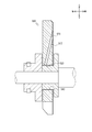
- FIG. 1 is a side sectional view showing an overall configuration of a turbocharger including a thrust bearing according to a first embodiment of the present invention.
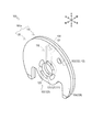
- the perspective view which showed the structure of the thrust bearing which concerns on 1st embodiment of this invention.
- (B) Similarly, the enlarged view of the part shown by S1 in Fig.4 (a).
- the side sectional view showing the state where the thrust bearing is arranged.
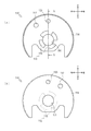
- the front view which similarly showed the structure of the 1st board
- B Similarly, a rear view.
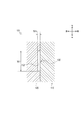
- A) Similarly, a cross-sectional view taken along line AA in FIG. 6 (a).
- FIG. 5 is a cross-sectional view taken along line CC in FIG. 4. Side surface sectional drawing which showed the state by which the thrust bearing which concerns on 2nd embodiment of this invention was arrange
- Plan sectional drawing which showed the structure of the lubricating oil path of the thrust bearing which concerns on 3rd embodiment of this invention.
- Side surface sectional drawing which showed the state by which the conventional thrust bearing was arrange
- the vertical direction, the horizontal direction, and the front-back direction are defined according to the arrows shown in the figure.
- the turbocharger 1 is for sending compressed air into the engine cylinder. As shown in FIG. 1, the turbocharger 1 mainly includes a shaft 10, a turbine 20, a compressor 30, and a bearing housing 40.
- the shaft 10 is arranged with its longitudinal direction (axial direction) directed in the front-rear direction.
- the compressor wheel 32 is fixed to one end (rear end) of the shaft 10
- the turbine wheel 22 is fixed to the other end (front end) of the shaft 10.
- the shaft 10 connects the compressor wheel 32 and the turbine wheel 22.
- the shaft 10 is rotatably supported in the bearing housing 40.
- the turbine 20 is disposed in front of the bearing housing 40.
- the turbine 20 mainly includes a turbine housing 21 and a turbine wheel 22.
- the turbine housing 21 contains the turbine wheel 22.
- the turbine housing 21 is fixed to the front end of the bearing housing 40 and is formed so as to cover the turbine wheel 22.
- the turbine wheel 22 is fixed to the shaft 10 and is configured to be rotatable integrally with the shaft 10.
- the compressor 30 is disposed behind the bearing housing 40.
- the compressor 30 mainly includes a compressor housing 31 and a compressor wheel 32.
- the compressor housing 31 contains the compressor wheel 32.
- the compressor housing 31 is fixed to the rear end of the bearing housing 40 and is formed so as to cover the compressor wheel 32.
- the compressor wheel 32 is fixed to the shaft 10 and is configured to be rotatable integrally with the shaft 10.
- the bearing housing 40 supports the shaft 10 so as to be rotatable.
- the bearing housing 40 is mainly provided with a sliding bearing portion 41, a thrust bearing portion 42, and an oil supply oil passage 45.
- the sliding bearing portion 41 is a portion that supports the shaft 10 so as to be rotatable.
- the sliding bearing portion 41 has a circular cross section and is formed so as to penetrate the bearing housing 40 in the front-rear direction.
- the sliding bearing portion 41 is provided with a sliding bearing 43 for smoothly rotating the shaft 10.
- the slide bearing 43 is fitted on the shaft 10.
- the thrust bearing portion 42 is a portion for supporting a thrust load acting in the axial direction of the shaft 10.
- the thrust bearing portion 42 is formed on the rear side surface of the bearing housing 40. More specifically, a recess recessed toward the front is formed on the rear side surface of the bearing housing 40. The space formed by the concave portion becomes the thrust bearing portion 42.
- a thrust bearing 100 for supporting a thrust load is disposed in the thrust bearing portion 42. The thrust bearing 100 is fitted on the shaft 10 via the first collar 11 and the second collar 12 and attached to the bearing housing 40.
- the first collar 11 includes a cylindrical portion 11 a whose axial direction is directed in the front-rear direction, and an extending portion 11 b that extends outward from the outer peripheral surface of the cylindrical portion 11 a.
- the second collar 12 includes a cylindrical portion 12a whose axial direction is directed in the front-rear direction, and an extending portion 12b that extends outward from the outer peripheral surface of the cylindrical portion 12a.
- the first collar 11 and the second collar 12 are closely attached to the shaft 10 in the front-rear direction.
- the first collar 11 and the second collar 12 are configured to be rotatable integrally with the shaft 10.
- the first collar 11 (more specifically, the extended portion 11 b of the first collar 11) and the second collar 12 (more specifically, the extension of the second collar 12).
- a thrust bearing 100 is arranged between the part 12b). The first collar 11 and the second collar 12 are rotated relative to the thrust bearing 100.
- the oil supply oil passage 45 is a hole for supplying (oil supply) lubricating oil to the slide bearing 43 and the thrust bearing 100.
- the oil supply passage 45 extends downward from a housing oil supply port 48 provided on the upper side surface of the bearing housing 40.
- the extension end portion (lower end portion) is connected to a first housing discharge port 49 provided in the sliding bearing portion 41.
- the housing oil supply port 48 and the first housing discharge port 49 communicate with each other, and the lubricating oil can be supplied to the slide bearing portion 41 (and thus the slide bearing 43).
- a second oil supply passage 46 in which the oil supply oil passage 45 is branched is formed in the middle of the oil supply oil passage 45 in the vertical direction.
- the second oil supply passage 46 extends rearward from a branch portion with the oil supply passage 45.
- the extension end portion (rear end portion) is connected to the second housing discharge port 50 provided in the thrust bearing portion 42.
- the housing oil supply port 48 and the second housing discharge port 50 communicate with each other, and the lubricating oil can be supplied to the thrust bearing portion 42 (and thus the thrust bearing 100).
- the turbine wheel 22 is rotated by high-temperature air (exhaust gas) after combustion in the cylinder of the engine. Then, the rotation of the turbine wheel 22 is transmitted to the compressor wheel 32 via the shaft 10, and the compressor wheel 32 is rotated.
- the compressed air can be supplied to the cylinder of the engine by rotating the compressor wheel 32.
- a thrust bearing 100 shown in FIGS. 2 to 5 is a member for supporting a thrust load acting in the axial direction of the shaft 10.
- the thrust bearing 100 includes a main body portion 100a, a through hole 101 provided mainly in the main body portion 100a, a pin hole 102, a sliding portion 103, a sliding material 104, and a lubricating oil passage 130. .
- the main body 100a is a main structure of the thrust bearing 100. As shown in FIGS. 2 to 5, the main body portion 100 a includes a first plate member 110 and a second plate member 120.
- the first plate member 110 is a member that forms the front portion of the main body portion 100 a, and is mainly an iron-based material (more specifically, excluding the front-side sliding material 114 described later). Consists of.
- plate material 110 is formed in the flat form which orient
- the first plate member 110 is provided with a front through-hole 111, a front pin hole 112, a front sliding portion 113, a front sliding member 114, and a lubricating oil supply port 133.
- the second plate member 120 is a member that forms the rear portion of the main body portion 100 a, and mainly (more specifically, a rear side sliding member described later). (Except 124) made of ferrous material.
- the second plate member 120 is formed in a flat plate shape with its plate surface directed in the front-rear direction.
- plate material 120 is formed in the substantially C-shape which orient
- the outer edge shape of the second plate member 120 is formed to be substantially the same as the outer edge shape of the first plate member 110.
- the second plate member 120 is provided with a rear through hole 121, a rear pin hole 122, a rear sliding portion 123, a rear sliding member 124, and a recess 132.
- the first plate member 110 and the second plate member 120 are overlapped to form the main body portion 100a.
- the first plate member 110 and the second plate member 120 are arranged to face each other in the front-rear direction, and the rear side surface of the first plate member 110 and the front side surface of the second plate member 120 are (of two plate members).
- the back metal is joined by laser joining.
- the main body 100a is formed in a flat plate shape in which the first plate member 110 and the second plate member 120 are integrated.
- plate material 120 is not limited to the laser joining as mentioned above, For example, it may be caulking, friction joining, press fit, etc.
- the through hole 101 of the main body 100a is a hole for allowing the shaft 10 (more specifically, the shaft 10 and the second collar 12 fitted to the shaft 10 to penetrate). Note that lubricating oil is supplied to the through hole 101 through a lubricating oil passage 130 as described later.
- the through hole 101 includes a front through hole 111 of the first plate member 110 and a rear through hole 121 of the second plate member 120.
- the front through-hole 111 of the first plate member 110 is a hole that forms the front of the through-hole 101 of the main body 100a.
- the front through-hole 111 is formed in the center of the first plate member 110 so as to have a perfect circle shape when viewed from the front and penetrate in the front-rear direction.
- the inner diameter of the front through hole 111 is slightly longer than the outer diameter of the cylindrical portion 12a of the second collar 12.
- the rear through hole 121 of the second plate member 120 is a hole that forms the rear part of the through hole 101 of the main body 100a.
- the rear side through-hole 121 is formed in the center of the second plate member 120 so as to have a perfect circle shape in front view and to penetrate in the front-rear direction.
- the inner diameter of the rear through-hole 121 is formed to be the same as the inner diameter of the front through-hole 111 (formed slightly longer than the outer diameter of the cylindrical portion 12a of the second collar 12).
- the rear side through-hole 121 is arrange
- the front side through hole 111 and the rear side through hole 121 are arranged continuously in the front-rear direction, and the through hole 101 of the main body 100a is formed. It is formed.
- the thrust bearing 100 is disposed in the turbocharger 1
- the shaft 10 and the second collar 12 that is externally fitted to the shaft 10 are passed through the through hole 101.
- a slight gap is formed between the outer peripheral surface of the inner peripheral surface second collar 12 (more specifically, the cylindrical portion 12a of the second collar 12) of the through hole 101, and the clearance is formed in the lubricating oil passage 130. This is the oil passage for the lubricating oil supplied to the through hole 101.
- the pin hole 102 of the main body 100a is a hole for inserting the thrust bearing 100 into a pin attached to the bearing housing 40.
- the pin hole 102 includes a front pin hole 112 of the first plate member 110 and a rear pin hole 122 of the second plate member 120.
- the front pin hole 112 of the first plate member 110 is a hole that forms the front part of the pin hole 102 of the main body 100a.
- the front pin hole 112 is formed in the upper left diagonal portion of the first plate member 110 so as to have a perfect circle shape in front view and penetrate in the front-rear direction.
- plate material 120 is a hole which comprises the rear part of the pin hole 102 of the main-body part 100a.
- the rear pin hole 122 is formed in the upper left diagonal portion of the second plate member 120 so as to have a perfect circle shape in front view and penetrate in the front-rear direction.
- the inner diameter of the rear pin hole 122 is formed to be the same as the inner diameter of the front pin hole 112.
- the rear pin hole 122 is disposed on the same axis as the front pin hole 112 in the main body 100a.
- the front pin hole 112 and the rear pin hole 122 are arranged continuously in the front-rear direction, and the pin hole 102 of the main body portion 100a is formed. It is formed.
- the thrust bearing 100 is disposed in the turbocharger 1, the position is determined by the pin being inserted into the pin hole 102 and the rotation is prevented.
- the sliding part 103 of the main body part 100a is a part for sliding the thrust bearing 100 on another member.
- the sliding part 103 of the main body part 100 a is configured by a front sliding part 113 of the first plate member 110 and a rear sliding part 123 of the second plate member 120.
- the front sliding portion 113 is a portion for sliding the front side surface of the thrust bearing 100 to another member (more specifically, the second collar 12).
- the front sliding portion 113 is formed in the vicinity of the front through hole 111 on the front side surface of the first plate member 110.
- a front tapered portion 115 is formed on the front sliding portion 113.
- the front taper portion 115 has an inclined surface that gently inclines in the circumferential direction.
- a plurality (four in this embodiment) of front taper portions 115 are provided.
- the plurality of front taper portions 115 are formed in the outer diameter direction from the front edge portion of the front through-hole 111 with appropriate intervals in the circumferential direction.
- the rear sliding portion 123 is a portion that slides the rear side surface of the thrust bearing 100 on another member (more specifically, the first collar 11).
- the rear sliding portion 123 is formed in the vicinity of the rear through hole 121 on the rear side surface of the second plate member 120.
- a rear tapered portion 125 is formed on the rear sliding portion 123.
- the rear taper portion 125 has an inclined surface that is gently inclined in the circumferential direction.
- a plurality of (four in the present embodiment) rear taper portions 125 are provided.
- the plurality of rear taper portions 125 are formed in the outer diameter direction from the rear edge portion of the rear through hole 121 with appropriate intervals in the circumferential direction.
- the main body 100a when the thrust bearing 100 is disposed in the turbocharger 1, the main body 100a is disposed on the sliding portion 103 on the front side surface of the main body 100a (that is, the front sliding portion 113 of the first plate member 110).
- the lubricating oil supplied to the through hole 101 is supplied into the front tapered portion 115 via the front edge of the front through hole 111.
- the lubricating oil supplied into the through hole 101 of the main body 100a is inserted into the rear sliding portion 103 (that is, the rear sliding portion 123 of the second plate member 120) on the rear side surface of the main body 100a. It is supplied to the rear taper portion 125 through the rear edge portion of the hole 121.
- the thrust bearing 100 can support a thrust load acting in the axial direction of the shaft 10, and can prevent seizure and abnormal wear (damage) in the sliding portion 103.
- the sliding member 104 of the main body 100a is a sintered layer formed so as to cover substantially the entire region of the outer surface (front side surface and rear side surface) of the thrust bearing 100.
- the sliding member 104 of the main body 100a is composed of a front sliding member 114 of the first plate member 110 and a rear sliding member 124 of the second plate member 120.
- the front sliding material 114 is a sintered layer formed so as to cover substantially the entire region of the front side surface of the thrust bearing 100.
- the front sliding member 114 is formed so as to cover substantially the entire region of the front side surface of the first plate member 110.
- the front sliding member 114 is made of a copper-based material having excellent wear resistance and seizure resistance (unlike iron-based materials).
- the first plate member 110 is configured as a bimetal material in which a layer of copper material (sliding material 104) is shown on a layer of iron material (base material).
- the thickness of the front sliding material 114 (copper-based material) layer (W1 in FIG. 7) is 0.28 mm to 0.75 mm, and the thickness of the iron-based material layer (FIG. 7 is set to be about 5% to 14% of W2).
- the rear sliding material 124 is a sintered layer formed so as to cover substantially the entire region of the rear side surface of the thrust bearing 100.
- the rear sliding member 124 is formed so as to cover substantially the entire region of the rear side surface of the second plate member 120.
- the rear sliding member 124 is made of a copper-based material having excellent wear resistance and seizure resistance (unlike iron-based materials).
- the second plate member 120 is configured as a bimetal material in which a layer of copper-based material (sliding material 104) is shown on a layer of iron-based material (base material).
- the thickness of the front sliding material 114 (copper-based material) layer (W3 in FIG. 9) is 0.28 mm to 0.75 mm, and the thickness of the iron-based material layer (FIG. 9 is set to be about 5% to 14% of W4).
- the sliding material 104 (the front sliding material 114 and the rear sliding material 124) is an embodiment of the “sliding material” according to the present invention, and is not limited to this configuration.
- the “sliding material” according to the present invention may be formed only on at least one of the front sliding material 114 and the rear sliding material 124.
- the “sliding material” according to the present invention may be formed on the inner peripheral surface of the through hole 101 of the main body 100a.
- the “sliding material” according to the present invention does not cover the iron-based material layer (base material) by sintering, but may cover the base material by plating or pressure welding.
- the lubricating oil passage 130 of the main body 100a is for supplying lubricating oil to the sliding portion 103 of the main body 100a.
- the lubricating oil passage 130 is formed by a concave portion 132 that is recessed inward (rearward) on the front side surface of the second plate member 120. More specifically, when the first plate member 110 and the second plate member 120 are overlapped to form the main body 100a, the space defined by the inner peripheral surface of the recess 132 and the rear side surface of the first plate member 110 is formed. Is configured as the lubricating oil passage 130.
- the recess 132 is formed by pressing on the front side surface of the second plate member 120.
- the lubricating oil passage 130 is formed in a substantially rectangular shape that is elongated in the left-right direction in a plan sectional view.
- the left and right (lateral) width (W5 in FIG. 10) of the lubricating oil passage 130 is set to 6 mm.
- the left and right (lateral) width of the lubricating oil passage 130 is formed to be shorter than the diameter of the rear through hole 121 of the second plate member 120.
- the front-rear (vertical) width (W6 in FIG. 9B and FIG. 10) of the lubricating oil passage 130 is set to 0.35 mm.
- the lubricating oil passage 130 is formed in a substantially rectangular shape elongated in the vertical direction when viewed from the front. More specifically, the lubricating oil passage 130 extends upward from the inner peripheral surface of the through hole 101 of the main body 100a (the front edge of the rear through hole 121 of the second plate member 120). That is, a substantially rectangular opening that is elongated in the left-right direction in a plan sectional view is formed along the inner peripheral surface of the inner peripheral surface of the through hole 101 of the main body 100a (see D1 in FIG. 8). The opening serves as a lubricant discharge port 134 for discharging the lubricant from the lubricant passage 130 to the through hole 101 of the main body 100a.
- the extending end portion (upper end portion) extending upward of the lubricating oil passage 130 is an upper end portion of the lubricating oil supply port 133 formed in the first plate member 110 at the vertical position of the main body portion 100a. And are formed so as to be substantially at the same position.
- Lubricating oil inlet 133 is a hole for feeding lubricating oil supplied by lubricating oil passage 45 and second lubricating oil passage 46 formed in bearing housing 40 into lubricating oil passage 130.
- the lubricating oil supply port 133 is formed in the upper center portion of the first plate member 110 so as to have a perfect circular shape in front view and penetrate in the front-rear direction.
- the lubricating oil supply inlet 133 is formed by punching the first plate material 110 by press working.
- the opening on the front side of the lubricating oil inlet 133 that is, the opening opened on the front side surface of the first plate member 110, is connected to the second housing discharge port 50 of the second oil supply passage 46 formed in the bearing housing 40.
- the opening on the rear side of the lubricating oil inlet 133 that is, the opening opened on the rear side surface of the first plate member 110 is connected to the upper edge portion of the recess 132 formed in the second plate member 120.
- the lubricating oil passage 130 is formed in a substantially rectangular shape elongated in the vertical direction when viewed from the front, and the lubricating oil supply port 133 disposed at the upper end and the lubricating oil discharge port 134 disposed at the lower end. Is configured to communicate with each other.
- the lubricating oil flowing through the oil supply passage 45 and the second oil supply passage 46 of the bearing housing 40 passes through the lubricant supply port 133, and more specifically, the lubricating oil passage 130, more specifically, the lubricating oil passage 130. Paid to the top. Then, the lubricating oil supplied to the upper part of the lubricating oil passage 130 flows downward and is discharged into the through hole 101 of the main body 100a through the lubricating oil discharge port 134. Note that the lubricating oil discharged into the through hole 101 is supplied to the sliding portion 103 as described above. That is, the lubricating oil passage 130 can supply lubricating oil to the sliding portion 103 of the main body 100a.
- the lubricating oil passage 910 connecting the lubricating oil supply port 920 and the lubricating oil discharge port 930 is in the vertical direction (the plate surface direction of the thrust bearing 900).
- it is formed in an oblique direction slightly inclined. That is, it is necessary to form a relatively elongated lubricating oil passage 910 in an oblique direction by drilling, which is difficult to process.
- the thrust bearing 100 when forming the lubricating oil passage 130, it is not necessary to form the lubricating oil passage 130 in an oblique direction by drilling, and the processing can be facilitated. it can.
- the recess 132 and the lubricating oil supply inlet 133 are formed by press working, and the first plate member 110 and the second plate member 120 are overlapped to form a lubricating oil passage. 130 can be easily formed. In this way, in the manufacturing process of the thrust bearing 100, the drilling that requires cutting tool consumption costs can be eliminated, so that the cost can be reduced.
- the lubricating oil passage 130, the concave portion 132, the lubricating oil inlet 133, and the lubricating oil outlet 134 are the “lubricating oil passage”, “recessed portion”, “lubricating oil inlet”, and “lubricating oil discharge” according to the present invention. It is one embodiment of the “exit” and is not limited to this configuration.
- the planar sectional shape of the “lubricating oil passage” according to the present invention may be a circular shape, a semicircular shape, a triangular shape, or the like.
- the “lubricating oil passage” according to the present invention may be branched toward the downstream side. Further, the “lubricating oil passage” according to the present invention may be appropriately bent to form the lubricating oil discharge port 134 at an arbitrary discharge location.
- the “concave portion” according to the present invention is not formed only on the second plate member 120, but only on the first plate member 110, or formed on both the second plate member 120 and the first plate member 110. May be.
- the “recess” according to the present invention is formed in both the second plate member 120 and the first plate member 110, the shape of each recess may be different.
- the “lubricating oil inlet” according to the present invention is not formed only in the first plate member 110 but is formed only in the second plate member 120, or formed in both the first plate member 110 and the second plate member 120. It may be a thing.
- the “lubricating oil discharge port” is not formed only in the through hole 101 of the main body portion 100 a, but the sliding portion 103 or the tapered portion (the front tapered portion 115) of the sliding portion 103. And the rear taper portion 125).
- FIGS. 11-14 the structure of the thrust bearing which concerns on another embodiment of this invention is demonstrated in detail using FIGS. 11-14.
- the description is abbreviate
- FIG. 11 shows a state in which the thrust bearing 200a according to the second embodiment of the present invention is arranged.
- the configuration of the thrust bearing 200 a is different from the configuration of the thrust bearing 100 according to the first embodiment of the present invention in that the sliding material 104 is formed so as to cover only the front side surface of the sliding portion 103. is there.
- the front sliding member 114 of the first plate member 110 is formed so as to cover only the front side surface of the front sliding portion 113 among the front side surfaces of the first plate member 110.
- the rear sliding member 124 of the second plate member 120 is formed so as to cover only the rear side surface of the rear sliding portion 123 among the rear side surfaces of the second plate member 120.
- FIGS. 12A to 12C show planar cross-sectional shapes of the thrust bearing 200b according to the third embodiment of the present invention, the thrust bearing 200c according to the fourth embodiment, and the thrust bearing 200d according to the fifth embodiment. ing.
- the configuration of the thrust bearing 200b, the thrust bearing 200c, and the thrust bearing 200d is different from the configuration of the thrust bearing 100 according to the first embodiment of the present invention in the first plate member 110 and the second plate member 120, respectively. It is a point where a recess is formed.
- a concave portion 133b that is curved forward in a plan sectional view is formed on the rear side surface of the first plate member 110.
- the front side surface of the second plate member 120 is formed with a concave portion 132b that is curved rearward in a plan sectional view.
- the lubricating oil passage 130b is configured such that the first plate member 110 and the second plate member 120 are overlapped, whereby the recess 133b of the first plate member 110 and the recess 132b of the second plate member 120 are connected to each other. It is formed in an elliptical shape that is elongated in the left-right direction in cross-sectional view.
- a recess 133c that is recessed in a substantially rectangular shape toward the front in a plan sectional view is formed on the rear side surface of the first plate member 110.
- the front side surface of the second plate member 120 is formed with a recess 132c that is recessed in a substantially rectangular shape toward the rear in a plan sectional view.
- the lubricating oil passage 130c is configured such that the first plate member 110 and the second plate member 120 are overlapped to connect the concave portion 133c of the first plate member 110 and the concave portion 132c of the second plate member 120 so as to be flat as a whole. It is formed in a rectangular shape that is elongated in the left-right direction in cross-sectional view.
- a concave portion 133d that is recessed in a substantially rectangular shape in the plan sectional view is formed on the left side of the rear side surface of the first plate member 110. Further, on the right side of the front side surface of the second plate member 120, a concave portion 132d that is recessed in a substantially rectangular shape toward the rear in a plan sectional view is formed.
- the first plate member 110 and the second plate member 120 are overlapped to connect the concave portion 133d of the first plate member 110 and the front side surface of the second plate member 120, and the first plate member 110 and the second plate member 120 are connected to each other.
- each of the lubricating oil passages 130d is formed in two rectangular shapes that are elongated in the left-right direction in plan sectional view as a whole, separated from each other in the left-right direction.
- the lubricating oil passage according to the present invention may be formed by not only the first plate member 110 but also the recesses provided in the second plate member 120, and the shape and arrangement in a plan sectional view are free. Can be set to That is, the lubricating oil passage according to the present invention has a high degree of design freedom and can be easily processed.
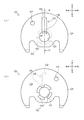
- the thrust bearing according to the sixth embodiment of the present invention By showing the front view of the two-plate material, the shape of the lubricating oil passage in a front view is shown. In these configurations, the difference from the configuration of the thrust bearing 100 according to the first embodiment of the present invention is the shape of the lubricating oil passage as viewed from the front (the shape of the recess).
- the recess 132e is formed in a substantially rectangular shape elongated in the vertical direction, The lower part is formed in a semi-annular shape along the upper edge of the rear through-hole 121.
- the lubricating oil discharge port 134e of the lubricating oil passage 130e is formed by an opening that is opened along the semicircular shape on the inner peripheral surface of the rear through-hole 121 (see D2 in FIG. 13). .
- the recess 132f is formed in a substantially rectangular shape elongated in the vertical direction, and the lower part is the rear part. It is formed in an annular shape along the edge of the side through hole 121.
- the lubricating oil outlet 134f of the lubricating oil passage 130f is formed by an opening that is opened over the entire inner peripheral surface of the rear side through-hole 121 (see D3 in FIG. 13). . That is, the lubricating oil can be supplied evenly to the inner peripheral surface of the through hole 101 of the main body 100a.
- the recess 132g is formed in a substantially rectangular shape elongated in the vertical direction, and the lower part is directed to the downstream side. And bifurcated and bent in two directions (left and right directions).
- the concave portion 132g branched and bent to the left side extends along the left side edge of the rear side through hole 121 on the left side (outside) of the rear side through hole 121 (the rear side through hole 121). Along the circumferential direction). And in the recessed part 132g branched to the left side, the lubricating oil discharge port 134g for discharging lubricating oil from the left side of the rear through hole 121 to the rear through hole 121 is at a position where it becomes an arbitrary discharge place. (See D4 on the left side in FIG. 14).
- the concave portion 132g branched and bent to the left side is further branched and bent toward the right side (the lubricating oil discharge port 134g side) at a position on the left side (that is, in the vicinity) of the lubricating oil discharge port 134g. Formed.
- the concave portion 132g branched and bent to the left is further branched and bent at a position near the lubricating oil discharge port 134g, but may be configured to be bent only without being branched. .
- the recessed part 132g branched and bent to the right side is along the right side edge part of the rear side through-hole 121 on the right side (outside) of the rear side through-hole 121 (the rear side through-hole 121 is arranged in the circumferential direction).
- the lubricating oil discharge port 134g for discharging lubricating oil from the right side of the rear side through-hole 121 to the said rear side through-hole 121 is formed in the position used as arbitrary discharge locations. (Refer to D4 on the right side in FIG. 14).
- the concave portion 132g branched and bent to the right side is branched and bent toward the left side (the lubricating oil discharge port 134g side) at a position on the right side (that is, in the vicinity) of the lubricating oil discharge port 134g. Formed.
- the extended (lower side) end part of the recessed part 132g branched to the left side and the right side is formed so as to merge below the rear side through-hole 121.
- the concave portion 132g branched and bent to the right side is further branched and bent at a position near the lubricating oil discharge port 134g, but may be configured to be bent without branching. .
- the lubricating oil passage according to the present invention can freely set the shape of the lubricating oil passage in the front view (the shape of the recess). That is, the lubricating oil passage according to the present invention has a high degree of design freedom and can be easily processed. Further, as in the thrust bearing according to the eighth embodiment, the lubricating oil passage can be branched and further bent appropriately, so that the number and arrangement locations of the lubricating oil discharge ports are set as desired. be able to. That is, the lubricating oil can be discharged to an arbitrary discharge location.
- the thrust bearing 100 is A main body 100a formed in a flat plate shape; A lubricating oil passage 130 formed in the main body 100a; A thrust bearing comprising: The main body 100a is formed by overlapping a first plate 110 and a second plate 120, The lubricating oil passage 130 is formed by a recess 132 provided on at least one overlapping surface of the first plate member 110 and the second plate member 120.
- the thrust bearing 100 can be easily processed when the lubricating oil passage 130 is formed.
- the main body 100a is provided with a through-hole 101 that penetrates the shaft 10.
- the lubricating oil passage 130 is provided with a lubricating oil discharge port 134.
- the lubricant discharge port 134 is preferably formed on at least one of the inner peripheral surface of the through hole 101 and the outer surface of the first plate member 110 and / or the second plate member 120.
- the lubricating oil passage 130 may be branched toward the downstream side.
- the lubricating oil discharge port 134 may be formed over the entire inner peripheral surface of the through hole 101.
- the lubricating oil passage 130 is formed outside the through hole 101 so as to extend along the circumferential direction of the through hole 101, and the lubricating oil passage 130 is in the vicinity of the lubricating oil discharge port 134 formed at an arbitrary discharge location. It may be branched or / and bent toward the oil discharge port 134 side.
- the lubricating oil passage 130 is provided with a lubricating oil inlet 133,
- the lubricant oil inlet 133 may be formed on the outer surface of the first plate member 110 or the second plate member 120.
- sliding member 104 may be formed on the surface layer of at least one outer surface of the first plate member 110 and the second plate member 120.
- a sliding portion 103 that slides with another member is formed on at least one outer surface of the first plate member 110 and the second plate member 120,
- the sliding material 104 may be formed only on the surface layer of the sliding portion 103.
- the thrust bearing 100 is preferably used for the turbocharger 1.
- the present invention can be used for a thrust bearing having a lubricating oil passage.
Landscapes
- Engineering & Computer Science (AREA)
- General Engineering & Computer Science (AREA)
- Mechanical Engineering (AREA)
- Chemical & Material Sciences (AREA)
- Oil, Petroleum & Natural Gas (AREA)
- Supercharger (AREA)
- Sliding-Contact Bearings (AREA)
Description
本発明は、潤滑油路を具備するスラスト軸受の技術に関する。
従来、潤滑油路を具備するスラスト軸受の技術は公知となっている。例えば、特許文献1に記載の如くである。
特許文献1に記載のスラスト軸受は、その内部に潤滑油路が形成されている。そして、前記スラスト軸受は、シャフトに貫通される貫通孔(ひいては、当該貫通孔の近傍に配置される、他の部材に摺動させる部分である摺動部)に、前記潤滑油路を介して潤滑油を供給することができる。これによって、前記スラスト軸受は、摺動部における焼き付きや異常摩耗(損傷)等を防止することができる。
以下では、図15を用いて、従来のスラスト軸受の構成をより詳細に説明する。図15に示すスラスト軸受900は、従来の一実施形態に係るスラスト軸受である。
図15に示すように、従来のスラスト軸受900は、その内部に潤滑油路910が形成されている。そして、潤滑油路910の潤滑油給入口920は、スラスト軸受900の前側面の上部に形成されている。他方、潤滑油路910の潤滑油吐出口930は、スラスト軸受900の貫通孔940の内周面に形成されている。これによって、潤滑油給入口920と潤滑油吐出口930とを結ぶ潤滑油路910は、上下方向(スラスト軸受900の板面方向)に対して若干傾斜した斜め方向に形成されることになる。
このように、従来のスラスト軸受900は、比較的細長い潤滑油路910をドリル加工により斜め方向に形成する必要があり、その加工が困難である点で不利であった。
本発明は以上の如き状況に鑑みてなされたものであり、その解決しようとする課題は、潤滑油路を形成する際に、その加工を容易とすることができるスラスト軸受を提供することである。
本発明の解決しようとする課題は以上の如くであり、次にこの課題を解決するための手段を説明する。
即ち、本発明のスラスト軸受は、平板状に形成される本体部と、前記本体部に形成される潤滑油路と、を具備するスラスト軸受であって、前記本体部は、第一板材と第二板材とが重ね合わされて形成され、前記潤滑油路は、前記第一板材及び前記第二板材の少なくとも一方の重ね合わせ面に設けられた凹部により形成されるものである。
本発明のスラスト軸受においては、前記本体部には、シャフトに貫通される貫通孔が設けられ、前記潤滑油路には、潤滑油吐出口が設けられ、前記潤滑油吐出口は、前記貫通孔の内周面と、前記第一板材または/及び前記第二板材の外側面と、の少なくとも一方に形成されるものである。
本発明のスラスト軸受においては、前記潤滑油路は、下流側へ向けて分岐するものである。
本発明のスラスト軸受においては、前記潤滑油吐出口は、前記貫通孔の内周面の全周に亘って形成されるものである。
本発明のスラスト軸受においては、前記潤滑油路は、前記貫通孔の外方で当該貫通孔を周方向に沿うように形成され、任意の吐出場所に形成された前記潤滑油吐出口の近傍で当該潤滑油吐出口側へ向けて分岐または/及び屈曲するものである。
本発明のスラスト軸受においては、前記潤滑油路には、潤滑油給入口が設けられ、前記潤滑油給入口は、前記第一板材または前記第二板材の外側面に形成されるものである。
本発明のスラスト軸受においては、前記第一板材及び前記第二板材の少なくとも一方の外側面の表層には摺動材が形成されるものである。
本発明のスラスト軸受においては、前記第一板材及び前記第二板材の少なくとも一方の外側面には、他の部材と摺動させる摺動部が形成され、前記摺動材は、前記摺動部の表層にのみ形成されるものである。
本発明のスラスト軸受においては、前記スラスト軸受は、ターボチャージャに用いられるものである。
本発明の効果として、以下に示すような効果を奏する。
本発明においては、潤滑油路を形成する際に、その加工を容易とすることができる。
以下では、図中に示した矢印に従って、上下方向、左右方向、及び前後方向を定義する。
まず、図1及び図5を用いて、本発明の第一実施形態に係るスラスト軸受100を具備するターボチャージャ1の構成について説明する。
ターボチャージャ1は、エンジンのシリンダに圧縮空気を送り込むためのものである。図1に示すように、ターボチャージャ1は、主としてシャフト10と、タービン20と、コンプレッサ30と、軸受ハウジング40と、を具備する。
シャフト10は、その長手方向(軸線方向)を前後方向へ向けて配置される。シャフト10の一端(後端)にはコンプレッサホイール32が固定され、シャフト10の他端(前端)にはタービンホイール22が固定される。このように、シャフト10は、コンプレッサホイール32とタービンホイール22とを連結する。シャフト10は、軸受ハウジング40内に回動可能に支持される。
タービン20は、軸受ハウジング40の前方に配置される。タービン20は、主としてタービンハウジング21と、タービンホイール22と、を具備する。
タービンハウジング21は、タービンホイール22を内包するものである。タービンハウジング21は、軸受ハウジング40の前端に固定され、タービンホイール22を覆うように形成される。タービンホイール22は、シャフト10に固定され、当該シャフト10と一体的に回動可能に構成される。
コンプレッサ30は、軸受ハウジング40の後方に配置される。コンプレッサ30は、主としてコンプレッサハウジング31と、コンプレッサホイール32と、を具備する。
コンプレッサハウジング31は、コンプレッサホイール32を内包するものである。コンプレッサハウジング31は、軸受ハウジング40の後端に固定され、コンプレッサホイール32を覆うように形成される。コンプレッサホイール32は、シャフト10に固定され、当該シャフト10と一体的に回動可能に構成される。
軸受ハウジング40は、シャフト10を回動可能に支持するものである。軸受ハウジング40には、主としてすべり軸受部41と、スラスト軸受部42と、給油油路45と、が設けられる。
すべり軸受部41は、シャフト10を回動可能に支持する部分である。すべり軸受部41は、円形断面を有し、軸受ハウジング40を前後方向に貫通するように形成される。すべり軸受部41には、シャフト10を滑らかに回動させるためのすべり軸受43が配置される。すべり軸受43は、シャフト10に外嵌される。
スラスト軸受部42は、シャフト10の軸線方向に作用するスラスト荷重を支承するための部分である。スラスト軸受部42は、軸受ハウジング40の後側面に形成される。より詳細には、軸受ハウジング40の後側面には、前方へ向けて凹んだ凹部が形成される。そして、当該凹部により形成された空間が、スラスト軸受部42となる。スラスト軸受部42には、スラスト荷重を支承するためのスラスト軸受100が配置される。スラスト軸受100は、第一カラー11及び第二カラー12を介してシャフト10に外嵌され、軸受ハウジング40に取り付けられる。
図5に示すように、第一カラー11は、その軸線方向を前後方向へ向けた円筒部11aと、当該円筒部11aの外周面から外方へ向けて延出した延出部11bと、により構成される。第二カラー12は、その軸線方向を前後方向へ向けた円筒部12aと、当該円筒部12aの外周面から外方へ向けて延出した延出部12bと、により構成される。第一カラー11及び第二カラー12は前後方向に密着して、シャフト10に外嵌される。そして、第一カラー11及び第二カラー12は、シャフト10と一体的に回動可能に構成される。
なお、図5に示すように、第一カラー11(より詳細には、当該第一カラー11の延出部11b)と、第二カラー12(より詳細には、当該第二カラー12の延出部12b)との間に、スラスト軸受100が配置される。第一カラー11及び第二カラー12は、スラスト軸受100に対して相対的に回動される
図1に示すように、給油油路45は、すべり軸受43及びスラスト軸受100に潤滑油を供給(給油)するための孔である。給油油路45は、軸受ハウジング40の上側面に設けられたハウジング給油口48から下方へ向けて延出される。そして、当該延出端部(下側端部)が、すべり軸受部41に設けられた第一ハウジング吐出口49に接続される。こうして、ハウジング給油口48と第一ハウジング吐出口49とが連通され、すべり軸受部41(ひいては、すべり軸受43)に潤滑油を供給することができる。
また、給油油路45の上下中途部には、当該給油油路45が分岐した第二給油油路46が形成される。第二給油油路46は、給油油路45との分岐部から後方へ向けて延出される。そして、当該延出端部(後側端部)が、スラスト軸受部42に設けられた第二ハウジング吐出口50に接続される。こうして、ハウジング給油口48と第二ハウジング吐出口50とが連通され、スラスト軸受部42(ひいては、スラスト軸受100)に潤滑油を供給することができる。
このように構成されたターボチャージャ1においては、エンジンのシリンダ内で燃焼した後の高温の空気(排気)によって、タービンホイール22が回動される。そして、当該タービンホイール22の回動は、シャフト10を介してコンプレッサホイール32に伝達され、当該コンプレッサホイール32が回動される。そして、コンプレッサホイール32が回動することにより、圧縮された空気を前記エンジンのシリンダへと供給することができる。
次に、スラスト軸受100の構成について、より詳細に説明する。
図2から図5までに示すスラスト軸受100は、シャフト10の軸線方向に作用するスラスト荷重を支承するための部材である。スラスト軸受100は、本体部100aと、主として当該本体部100aに設けられる貫通孔101と、ピン孔102と、摺動部103と、摺動材104と、潤滑油路130と、により構成される。
本体部100aは、スラスト軸受100の主たる構造体である。本体部100aは、図2から図5までに示すように、第一板材110と、第二板材120と、により構成される。
第一板材110は、図2から図7までに示すように、本体部100aの前部を成す部材であり、主として(より詳細には、後述する前側摺動材114を除いて)鉄系材料により構成される。第一板材110は、その板面を前後方向へ向けた平板状に形成される。また、第一板材110は、正面視で開口する側を下方へ向けた略C字状に形成される。より詳細には、第一板材110は、正面視で略真円形状の部材が、当該第一板材110の中央部を残した状態で下方から上方へ向けて切り欠いた形状に形成される。第一板材110には、前側貫通孔111と、前側ピン孔112と、前側摺動部113と、前側摺動材114と、潤滑油給入口133と、が設けられる。
第二板材120は、図2から図5までと、図8及び図9とに示すように、本体部100aの後部を成す部材であり、主として(より詳細には、後述する後側摺動材124を除いて)鉄系材料により構成される。第二板材120は、その板面を前後方向へ向けた平板状に形成される。また、第二板材120は、正面視で開口する側を下方へ向けた略C字状に形成される。より詳細には、第二板材120は、正面視で略真円形状の部材が、当該第二板材120の中央部を残した状態で下方から上方へ向けて切り欠いた形状に形成される。こうして、第二板材120の外縁形状は、第一板材110の外縁形状と略同一となるように形成される。第二板材120には、後側貫通孔121と、後側ピン孔122と、後側摺動部123と、後側摺動材124と、凹部132と、が設けられる。
このような構成において、第一板材110と第二板材120とが重ね合わされて、本体部100aが形成される。
また、単に重ねるだけではなく、第一板材110と第二板材120とを貼り合せることで本体部100aを形成してもよい。より詳細には、第一板材110と第二板材120とが前後方向に対向して配置され、当該第一板材110の後側面と当該第二板材120の前側面とが(2枚の板材の裏金どうしが)レーザー接合により接合される。こうして、本体部100aは、第一板材110と第二板材120とが一体化した平板状に形成される。
また、単に重ねるだけではなく、第一板材110と第二板材120とを貼り合せることで本体部100aを形成してもよい。より詳細には、第一板材110と第二板材120とが前後方向に対向して配置され、当該第一板材110の後側面と当該第二板材120の前側面とが(2枚の板材の裏金どうしが)レーザー接合により接合される。こうして、本体部100aは、第一板材110と第二板材120とが一体化した平板状に形成される。
なお、第一板材110と第二板材120との貼り合わせの加工方法は、前述の如きレーザー接合に限定するものではなく、例えばかしめや、摩擦接合、圧入等であってもよい。
本体部100aの貫通孔101は、シャフト10(より詳細には、シャフト10及び当該シャフト10に外嵌される第二カラー12)を貫通させるための孔である。なお、貫通孔101には、後述するように、潤滑油路130により潤滑油が供給される。貫通孔101は、第一板材110の前側貫通孔111と、第二板材120の後側貫通孔121と、により構成される。
第一板材110の前側貫通孔111は、本体部100aの貫通孔101の前部を成す孔である。前側貫通孔111は、第一板材110の中央に、正面視で真円形状であって前後方向に貫通して形成される。前側貫通孔111の内径は、第二カラー12の円筒部12aの外径よりも若干長く形成される。
第二板材120の後側貫通孔121は、本体部100aの貫通孔101の後部を成す孔である。後側貫通孔121は、第二板材120の中央に、正面視で真円形状であって前後方向に貫通して形成される。後側貫通孔121の内径は、前側貫通孔111の内径と同一となるように形成される(第二カラー12の円筒部12aの外径よりも若干長く形成される)。なお、後側貫通孔121は、本体部100aにおいて、前側貫通孔111と同一軸線上に配置される。
このような構成において、第一板材110と第二板材120とが重ね合わされると、前側貫通孔111と後側貫通孔121とが前後方向に連なって配置され、本体部100aの貫通孔101が形成される。そして、図5に示すように、スラスト軸受100がターボチャージャ1に配置された場合、貫通孔101には、シャフト10及び当該シャフト10に外嵌された第二カラー12が貫通される。また、貫通孔101の内周面第二カラー12(より詳細には、第二カラー12の円筒部12a)の外周面との間には若干の隙間が形成され、当該隙間は潤滑油路130から貫通孔101に供給された潤滑油の油路となる。
本体部100aのピン孔102は、スラスト軸受100を軸受ハウジング40に取り付けられたピンに挿入するための孔である。ピン孔102は、第一板材110の前側ピン孔112と、第二板材120の後側ピン孔122と、により構成される。
第一板材110の前側ピン孔112は、本体部100aのピン孔102の前部を成す孔である。前側ピン孔112は、第一板材110の左斜め上部に、正面視で真円形状であって前後方向に貫通して形成される。
第二板材120の後側ピン孔122は、本体部100aのピン孔102の後部を成す孔である。後側ピン孔122は、第二板材120の左斜め上部に、正面視で真円形状であって前後方向に貫通して形成される。後側ピン孔122の内径は、前側ピン孔112の内径と同一となるように形成される。なお、後側ピン孔122は、本体部100aにおいて、前側ピン孔112と同一軸線上に配置される。
このような構成において、第一板材110と第二板材120とが重ね合わされると、前側ピン孔112と後側ピン孔122とが前後方向に連なって配置され、本体部100aのピン孔102が形成される。そして、スラスト軸受100がターボチャージャ1に配置された場合、ピン孔102にピンが挿通されることで位置が決まり、回り止めされる。
本体部100aの摺動部103は、スラスト軸受100を他の部材に摺動させる部分である。本体部100aの摺動部103は、第一板材110の前側摺動部113と、第二板材120の後側摺動部123と、により構成される。
前側摺動部113は、スラスト軸受100の前側面を他の部材(より詳細には、第二カラー12)に摺動させる部分である。前側摺動部113は、第一板材110の前側面のうち前側貫通孔111の近傍に形成される。前側摺動部113には、前側テーパ部115が形成される。前側テーパ部115は、周方向へ向けて緩やかに傾斜する傾斜面を有する。前側テーパ部115は、複数(本実施形態では、4つ)設けられる。複数の前側テーパ部115は、周方向に適宜の間隔をあけ、前側貫通孔111の前側縁部から外径方向にそれぞれ形成される。
後側摺動部123は、スラスト軸受100の後側面を他の部材(より詳細には、第一カラー11)に摺動させる部分である。後側摺動部123は、第二板材120の後側面のうち後側貫通孔121の近傍に形成される。後側摺動部123には、後側テーパ部125が形成される。後側テーパ部125は、周方向へ向けて緩やかに傾斜する傾斜面を有する。後側テーパ部125は、複数(本実施形態では、4つ)設けられる。複数の後側テーパ部125は、周方向に適宜の間隔をあけ、後側貫通孔121の後側縁部から外径方向にそれぞれ形成される。
このような構成において、スラスト軸受100がターボチャージャ1に配置された場合、本体部100aの前側面の摺動部103(すなわち、第一板材110の前側摺動部113)には、本体部100aの貫通孔101に供給された潤滑油が、前側貫通孔111の前側縁部を介して前側テーパ部115内に供給される。また、本体部100aの後側面の摺動部103(すなわち、第二板材120の後側摺動部123)には、本体部100aの貫通孔101内に供給された潤滑油が、後側貫通孔121の後側縁部を介して後側テーパ部125に供給される。
こうして、本体部100aの摺動部103に潤滑油が供給された場合、シャフト10に外嵌される第二カラー12及び第一カラー11がスラスト軸受100に対して相対的に回動することにより、摺動部103の前側テーパ部115及び後側テーパ部125内に供給された潤滑油の圧力が高くなる。すなわち、シャフト10の軸線方向に作用するスラスト荷重が生じたとしても、当該スラスト荷重を抑制する方向へ向けての圧力が生じることになる。その結果、スラスト軸受100は、シャフト10の軸線方向に作用するスラスト荷重を支承することができ、摺動部103における焼き付きや異常摩耗(損傷)等を防止することができる。
本体部100aの摺動材104は、スラスト軸受100の外側面(前側面及び後側面)の略全領域を覆うように形成された焼結層である。本体部100aの摺動材104は、第一板材110の前側摺動材114と、第二板材120の後側摺動材124と、により構成される。
前側摺動材114は、スラスト軸受100の前側面の略全領域を覆うように形成された焼結層である。前側摺動材114は、第一板材110の前側面の略全領域を覆うように形成される。前側摺動材114は、(鉄系材料とは異なり)優れた耐摩耗性、耐焼き付き性を有する銅系材料により構成される。
こうして、第一板材110は、鉄系材料の層(基材)に銅系材料の層(摺動材104)が披着されたバイメタル材として構成される。なお、本実施形態において、前側摺動材114(銅系材料)の層の厚さ(図7中のW1)は0.28mm~0.75mmであり、鉄系材料の層の厚さ(図7中のW2)の5%~14%程度となるように設定される。
後側摺動材124は、スラスト軸受100の後側面の略全領域を覆うように形成された焼結層である。後側摺動材124は、第二板材120の後側面の略全領域を覆うように形成される。後側摺動材124は、(鉄系材料とは異なり)優れた耐摩耗性、耐焼き付き性を有する銅系材料により構成される。
こうして、第二板材120は、鉄系材料の層(基材)に銅系材料の層(摺動材104)が披着されたバイメタル材として構成される。なお、本実施形態において、前側摺動材114(銅系材料)の層の厚さ(図9中のW3)は0.28mm~0.75mmであり、鉄系材料の層の厚さ(図9中のW4)の5%~14%程度となるように設定される。
このような構成により、スラスト軸受100を構成する全ての材料を銅系材料とする場合と比べて、必要な場所だけ、すなわち(スラスト軸受100のうち他の部材と摺動させる摺動部103を有する)前側面及び後側面の表層だけを優れた耐摩耗性、耐焼き付き性を有する銅系材料とし、その他の場所を比較的安価な鉄系材料とするため、コストの低減を図ることができる。
なお、摺動材104(前側摺動材114及び後側摺動材124)は、本発明に係る「摺動材」の一実施形態であり、この構成に限定するものではない。
例えば、本発明に係る「摺動材」は、前側摺動材114及び後側摺動材124の少なくとも一方のみに形成するものであってもよい。また、本発明に係る「摺動材」は、本体部100aの貫通孔101の内周面に形成してもよい。また、本発明に係る「摺動材」は、焼結により鉄系材料の層(基材)を覆うようにするものでなく、めっきや圧接により基材を覆うようにするものでもよい。
次に、本体部100aの潤滑油路130の構成について、より詳細に説明する。
本体部100aの潤滑油路130は、当該本体部100aの摺動部103に潤滑油を供給するためのものである。潤滑油路130は、第二板材120の前側面に内方(後方)へ向けて凹んだ凹部132により形成される。より詳細には、第一板材110と第二板材120とが重ね合わされて本体部100aが形成された場合に、凹部132の内周面と第一板材110の後側面とにより区画形成された空間が、潤滑油路130として構成される。なお、凹部132は、第二板材120の前側面にプレス加工により成形される。
潤滑油路130は、図10に示すように、平面断面視で左右方向に細長い略長方形状に形成される。本実施形態では、潤滑油路130の左右(横)幅(図10中のW5)は、6mmに設定される。なお、潤滑油路130の左右(横)幅は、第二板材120の後側貫通孔121の直径よりも短く形成される。また、潤滑油路130の前後(縦)幅(図9(b)中及び図10中のW6)は、0.35mmに設定される。
潤滑油路130は、図2及び図8に示すように、正面視で上下方向に細長い略長方形状に形成される。より詳細には、潤滑油路130は、本体部100aの貫通孔101の内周面(第二板材120の後側貫通孔121の前側縁部)から上方へ向けて延出される。すなわち、本体部100aの貫通孔101の内周面には、平面断面視で左右方向に細長い略長方形状の開口部が当該内周面に沿って形成される(図8中のD1参照)。そして、当該開口部は、潤滑油路130から本体部100aの貫通孔101へ潤滑油を吐出するための、潤滑油吐出口134となる。
また、前記潤滑油路130の上方へ向けての延出端部(上側端部)は、本体部100aの上下方向位置において、第一板材110に形成される潤滑油給入口133の上側端部と略同一位置となるように形成される。
潤滑油給入口133は、軸受ハウジング40に形成された給油油路45及び第二給油油路46により供給される潤滑油を潤滑油路130に給入させるための孔である。潤滑油給入口133は、第一板材110の中央上部に、正面視で真円形状であって前後方向に貫通して形成される。なお、潤滑油給入口133は、プレス加工により第一板材110を打ち抜いて形成される。
潤滑油給入口133の前側の開口部、すなわち第一板材110の前側面に開口された開口部は、軸受ハウジング40に形成された第二給油油路46の第二ハウジング吐出口50に接続される。また、潤滑油給入口133の後側の開口部、すなわち第一板材110の後側面に開口された開口部は、第二板材120に形成された凹部132の上側縁部に接続される。
こうして、潤滑油路130は、正面視で上下方向に細長い略長方形状に形成されると共に、上側端部に配置される潤滑油給入口133と下側端部に配置される潤滑油吐出口134とが連通されるように構成される。
このような構成により、軸受ハウジング40の給油油路45及び第二給油油路46を流れる潤滑油は、潤滑油給入口133を介して、潤滑油路130、より詳細には潤滑油路130の上部に給入される。そして、当該潤滑油路130の上部に給入された潤滑油は、下方へ向けて流れ、潤滑油吐出口134を介して本体部100aの貫通孔101内に吐出される。なお、貫通孔101内に吐出された潤滑油は、前述の如く摺動部103へと供給される。すなわち、潤滑油路130は、本体部100aの摺動部103に潤滑油を供給することができる。
ここで、図15に示すように、従来のスラスト軸受900においては、潤滑油給入口920と潤滑油吐出口930とを結ぶ潤滑油路910が、上下方向(スラスト軸受900の板面方向)に対して若干傾斜した斜め方向に形成される。すなわち、比較的細長い潤滑油路910をドリル加工により斜め方向に形成する必要があり、その加工が困難であった。
しかしながら、本発明の一実施形態に係るスラスト軸受100は、潤滑油路130を形成する際に、ドリル加工により斜め方向に潤滑油路130を形成する必要がなく、その加工を容易とすることができる。
より詳細には、スラスト軸受100は、その製造工程において、凹部132及び潤滑油給入口133をそれぞれプレス加工により形成し、第一板材110と第二板材120とを重ね合わせることで、潤滑油路130を容易に形成することができる。このように、スラスト軸受100の製造工程において、刃具消耗費が掛かるドリル加工を廃止することができるので、コストの低減を図ることができる。
なお、潤滑油路130、凹部132、潤滑油給入口133、及び潤滑油吐出口134は、本発明に係る「潤滑油路」、「凹部」、「潤滑油給入口」、及び「潤滑油吐出口」の一実施形態であり、この構成に限定するものではない。
例えば、本発明に係る「潤滑油路」の平面断面視形状は、円形状や、半円形状や、三角形状等であってもよい。また、本発明に係る「潤滑油路」は、下流側へ向けて分岐するものであってもよい。また、本発明に係る「潤滑油路」は、適宜に曲折させることにより、任意の吐出場所に潤滑油吐出口134を形成してもよい。
また、本発明に係る「凹部」は、第二板材120だけに形成するものでなく、第一板材110だけに形成したり、第二板材120及び第一板材110の両方に形成するものであってもよい。また、本発明に係る「凹部」は、第二板材120及び第一板材110の両方に形成した場合には、それぞれの凹部の形状を異なるものとしてもよい。
また、本発明に係る「潤滑油給入口」は、第一板材110だけに形成するものでなく、第二板材120だけに形成したり、第一板材110及び第二板材120の両方に形成するものであってもよい。
また、本発明に係る「潤滑油吐出口」は、本体部100aの貫通孔101だけに形成するものでなく、摺動部103や、当該摺動部103のうち、テーパ部(前側テーパ部115及び後側テーパ部125)に形成するものであってもよい。
以下では、図11から図14を用いて、本発明の別実施形態に係るスラスト軸受の構成について、より詳細に説明する。
なお、本発明の第一実施形態に係るスラスト軸受100の構成と同一箇所については、図中に同一の符号を付することで、その説明を省略する。
なお、本発明の第一実施形態に係るスラスト軸受100の構成と同一箇所については、図中に同一の符号を付することで、その説明を省略する。
図11では、本発明の第二実施形態に係るスラスト軸受200aが配置された状態を示している。スラスト軸受200aの構成において、本発明の第一実施形態に係るスラスト軸受100の構成と異なる点は、摺動材104が、摺動部103の表側面のみを覆うように形成されている点である。
より詳細には、第一板材110の前側摺動材114は、当該第一板材110の前側面のうち、前側摺動部113の前側面のみを覆うように形成されている。また、第二板材120の後側摺動材124は、当該第二板材120の後側面のうち、後側摺動部123の後側面のみを覆うように形成されている。
このような構成により、最低限必要な場所だけ、すなわちスラスト軸受200aのうち他の部材と摺動させる摺動部103の表層だけを優れた耐摩耗性、耐焼き付き性を有する銅系材料とし、その他の場所を比較的安価な鉄系材料とするため、コストの低減をより一層図ることができる。
図12(a)から(c)では、本発明の第三実施形態に係るスラスト軸受200b、第四実施形態に係るスラスト軸受200c、及び第五実施形態に係るスラスト軸受200dの平面断面形状を示している。これらの、スラスト軸受200b、スラスト軸受200c、及びスラスト軸受200dの構成において、本発明の第一実施形態に係るスラスト軸受100の構成と異なる点は、第一板材110及び第二板材120のそれぞれに凹部が形成される点である。
より詳細には、図12(a)に示すように、スラスト軸受200bにおいて、第一板材110の後側面には、平面断面視で前方へ向けて湾曲した凹部133bが形成される。また、第二板材120の前側面には、平面断面視で後方へ向けて湾曲した凹部132bが形成される。そして、潤滑油路130bは、第一板材110と第二板材120とが重ね合わされることにより、当該第一板材110の凹部133bと当該第二板材120の凹部132bとが接続され、全体として平面断面視で左右方向に細長い楕円状に形成される。
また、図12(b)に示すように、スラスト軸受200cにおいて、第一板材110の後側面には、平面断面視で前方へ向けて略長方形状に凹んだ凹部133cが形成される。また、第二板材120の前側面には、平面断面視で後方へ向けて略長方形状に凹んだ凹部132cが形成される。そして、潤滑油路130cは、第一板材110と第二板材120とが重ね合わされることにより、当該第一板材110の凹部133cと当該第二板材120の凹部132cとが接続され、全体として平面断面視で左右方向に細長い長方形状に形成される。
また、図12(c)に示すように、スラスト軸受200dにおいて、第一板材110の後側面の左側には、平面断面視で前方へ向けて略長方形状に凹んだ凹部133dが形成される。また、第二板材120の前側面の右側には、平面断面視で後方へ向けて略長方形状に凹んだ凹部132dが形成される。そして、潤滑油路130dは、第一板材110と第二板材120とが重ね合わせられることにより、当該第一板材110の凹部133dと第二板材120の前側面とが接続され、また、当該第二板材120の凹部132dと第一板材110の後側面とが接続されて形成される。すなわち、潤滑油路130dは、それぞれ全体として平面断面視で左右方向に細長い長方形状のものが、左右に離間して2つ形成される。
このように、本発明に係る潤滑油路は、第一板材110だけでなく、第二板材120に設けられた凹部により形成される構成であってもよく、平面断面視における形状や配置を自由に設定することができる。すなわち、本発明に係る潤滑油路は、設計自由度が高く、容易に加工することができる。
図13(a)及び(b)と、図14では、本発明の第六実施形態に係るスラスト軸受、第七実施形態に係るスラスト軸受、及び第八実施形態に係るスラスト軸受の、それぞれの第二板材の正面図を示すことにより、潤滑油路の正面視での形状を示している。これらの構成において、本発明の第一実施形態に係るスラスト軸受100の構成と異なる点は、潤滑油路の正面視での形状(凹部の形状)である。
より詳細には、図13(a)に示すように、本発明の第六実施形態に係るスラスト軸受の第二板材120eでは、凹部132eは、上下方向に細長い略長方形状に形成されると共に、下部が後側貫通孔121の上側縁部に沿った半環状に形成される。これによって、潤滑油路130eの潤滑油吐出口134eは、後側貫通孔121の内周面に半環状に沿って開口された開口部により形成されることになる(図13中のD2参照)。
また、図13(b)に示すように、本発明の第七実施形態に係るスラスト軸受の第二板材120fでは、凹部132fは、上下方向に細長い略長方形状に形成されると共に、下部が後側貫通孔121の縁部に沿った環状に形成される。これによって、潤滑油路130fの潤滑油吐出口134fは、後側貫通孔121の内周面の全周に亘って開口された開口部により形成されることになる(図13中のD3参照)。すなわち、本体部100aの貫通孔101の内周面に、潤滑油をムラ無く供給することができる。
また、図14に示すように、本発明の第八実施形態に係るスラスト軸受の第二板材120gでは、凹部132gは、上下方向に細長い略長方形状に形成されると共に、下部が下流側へ向けて2方向(左右方向)に分岐及び曲折して形成される。
より詳細には、左側に分岐及び曲折した凹部132gは、後側貫通孔121の左方(外方)にて当該後側貫通孔121の左側縁部を沿うように(当該後側貫通孔121を周方向に沿うように)形成される。そして、当該左側に分岐した凹部132gには、後側貫通孔121の左方から当該後側貫通孔121に潤滑油を吐出するための潤滑油吐出口134gが、任意の吐出場所となる位置に形成される(図14中の左側のD4参照)。そして、当該左側に分岐及び曲折した凹部132gは、前記潤滑油吐出口134gの左方(すなわち、近傍)となる位置で、さらに右方(前記潤滑油吐出口134g側)へ向けて分岐及び屈曲して形成される。
なお、本実施形態では、左側に分岐及び曲折した凹部132gは、潤滑油吐出口134gの近傍となる位置でさらに分岐及び屈曲しているが、分岐せずに屈曲だけさせる構成であってもよい。
なお、本実施形態では、左側に分岐及び曲折した凹部132gは、潤滑油吐出口134gの近傍となる位置でさらに分岐及び屈曲しているが、分岐せずに屈曲だけさせる構成であってもよい。
また、右側に分岐及び曲折した凹部132gは、後側貫通孔121の右方(外方)にて当該後側貫通孔121の右側縁部を沿うように(当該後側貫通孔121を周方向に沿うように)形成される。そして、当該右側に分岐した凹部132gには、後側貫通孔121の右方から当該後側貫通孔121に潤滑油を吐出するための潤滑油吐出口134gが任意の吐出場所となる位置に形成される(図14中の右側のD4参照)。そして、当該右側に分岐及び曲折した凹部132gは、前記潤滑油吐出口134gの右方(すなわち、近傍)となる位置で、さらに左方(前記潤滑油吐出口134g側)へ向けて分岐及び屈曲して形成される。なお、左側及び右側に分岐した凹部132gの延出(下方側)端部は、後側貫通孔121の下方で合流するように形成される。
なお、本実施形態では、右側に分岐及び曲折した凹部132gは、潤滑油吐出口134gの近傍となる位置でさらに分岐及び屈曲しているが、分岐せずに屈曲だけさせる構成であってもよい。
なお、本実施形態では、右側に分岐及び曲折した凹部132gは、潤滑油吐出口134gの近傍となる位置でさらに分岐及び屈曲しているが、分岐せずに屈曲だけさせる構成であってもよい。
このように、本発明に係る潤滑油路は、潤滑油路の正面視での形状(凹部の形状)を自由に設定することができる。すなわち、本発明に係る潤滑油路は、設計自由度が高く、容易に加工することができる。また、第八実施形態に係るスラスト軸受のように、潤滑油路を分岐させることができ、さらには適宜に曲折させることができるので、潤滑油吐出口の数や配置場所を所望のものとすることができる。すなわち、潤滑油を任意の吐出場所へ吐出させることができる。
以上のように、スラスト軸受100は、
平板状に形成される本体部100aと、
前記本体部100aに形成される潤滑油路130と、
を具備するスラスト軸受であって、
前記本体部100aは、第一板材110と第二板材120とが重ね合わされて形成され、
前記潤滑油路130は、前記第一板材110及び前記第二板材120の少なくとも一方の重ね合わせ面に設けられた凹部132により形成されるものである。
平板状に形成される本体部100aと、
前記本体部100aに形成される潤滑油路130と、
を具備するスラスト軸受であって、
前記本体部100aは、第一板材110と第二板材120とが重ね合わされて形成され、
前記潤滑油路130は、前記第一板材110及び前記第二板材120の少なくとも一方の重ね合わせ面に設けられた凹部132により形成されるものである。
このような構成により、スラスト軸受100は、潤滑油路130を形成する際に、その加工を容易とすることができる。
また、スラスト軸受100においては、
前記本体部100aには、シャフト10に貫通される貫通孔101が設けられ、
前記潤滑油路130には、潤滑油吐出口134が設けられ、
前記潤滑油吐出口134は、前記貫通孔101の内周面と、前記第一板材110または/及び前記第二板材120の外側面と、の少なくとも一方に形成されることが望ましい。
前記本体部100aには、シャフト10に貫通される貫通孔101が設けられ、
前記潤滑油路130には、潤滑油吐出口134が設けられ、
前記潤滑油吐出口134は、前記貫通孔101の内周面と、前記第一板材110または/及び前記第二板材120の外側面と、の少なくとも一方に形成されることが望ましい。
また、前記潤滑油路130は、下流側へ向けて分岐させてもよい。
また、前記潤滑油吐出口134は、前記貫通孔101の内周面の全周に亘って形成させてもよい。
また、前記潤滑油路130は、前記貫通孔101の外方で当該貫通孔101を周方向に沿うように形成され、任意の吐出場所に形成された前記潤滑油吐出口134の近傍で当該潤滑油吐出口134側へ向けて分岐または/及び屈曲させてもよい。
また、前記潤滑油路130には、潤滑油給入口133が設けられ、
前記潤滑油給入口133は、前記第一板材110または前記第二板材120の外側面に形成させてもよい。
前記潤滑油給入口133は、前記第一板材110または前記第二板材120の外側面に形成させてもよい。
また、前記第一板材110及び前記第二板材120の少なくとも一方の外側面の表層には摺動材104が形成させてもよい。
また、前記第一板材110及び前記第二板材120の少なくとも一方の外側面には、他の部材と摺動させる摺動部103が形成され、
前記摺動材104は、前記摺動部103の表層にのみ形成させてもよい。
前記摺動材104は、前記摺動部103の表層にのみ形成させてもよい。
また、前記スラスト軸受100は、ターボチャージャ1に用いられることが望ましい。
本発明は、潤滑油路を具備するスラスト軸受に利用可能である。
1 ターボチャージャ
10 シャフト
22 タービンホイール
32 コンプレッサホイール
100 スラスト軸受
100a 本体部
101 貫通孔
103 摺動部
104 摺動材
110 第一板材
120 第二板材
130 潤滑油路
132 凹部
133 潤滑油給入口
134 潤滑油吐出口
10 シャフト
22 タービンホイール
32 コンプレッサホイール
100 スラスト軸受
100a 本体部
101 貫通孔
103 摺動部
104 摺動材
110 第一板材
120 第二板材
130 潤滑油路
132 凹部
133 潤滑油給入口
134 潤滑油吐出口
Claims (9)
- 平板状に形成される本体部と、
前記本体部に形成される潤滑油路と、
を具備するスラスト軸受であって、
前記本体部は、第一板材と第二板材とが重ね合わされて形成され、
前記潤滑油路は、前記第一板材及び前記第二板材の少なくとも一方の重ね合わせ面に設けられた凹部により形成されることを特徴とする、
スラスト軸受。 - 前記本体部には、シャフトに貫通される貫通孔が設けられ、
前記潤滑油路には、潤滑油吐出口が設けられ、
前記潤滑油吐出口は、前記貫通孔の内周面と、前記第一板材または/及び前記第二板材の外側面と、の少なくとも一方に形成されることを特徴とする、
請求項1に記載のスラスト軸受。 - 前記潤滑油路は、下流側へ向けて分岐することを特徴とする、
請求項2に記載のスラスト軸受。 - 前記潤滑油吐出口は、前記貫通孔の内周面の全周に亘って形成されることを特徴とする、
請求項2に記載のスラスト軸受。 - 前記潤滑油路は、前記貫通孔の外方で当該貫通孔を周方向に沿うように形成され、任意の吐出場所に形成された前記潤滑油吐出口の近傍で当該潤滑油吐出口側へ向けて分岐または/及び屈曲することを特徴とする、
請求項2または請求項3に記載のスラスト軸受。 - 前記潤滑油路には、潤滑油給入口が設けられ、
前記潤滑油給入口は、前記第一板材または前記第二板材の外側面に形成されることを特徴とする、
請求項1から請求項5までのいずれか一項に記載のスラスト軸受。 - 前記第一板材及び前記第二板材の少なくとも一方の外側面の表層には摺動材が形成されることを特徴とする、
請求項1から請求項6までのいずれか一項に記載のスラスト軸受。 - 前記第一板材及び前記第二板材の少なくとも一方の外側面には、他の部材と摺動させる摺動部が形成され、
前記摺動材は、前記摺動部の表層にのみ形成されることを特徴とする、
請求項7に記載のスラスト軸受。 - 前記スラスト軸受は、ターボチャージャに用いられることを特徴とする、
請求項1から請求項8までのいずれか一項に記載のスラスト軸受。
Applications Claiming Priority (2)
| Application Number | Priority Date | Filing Date | Title |
|---|---|---|---|
| JP2012-225378 | 2012-10-10 | ||
| JP2012225378A JP6025488B2 (ja) | 2012-10-10 | 2012-10-10 | スラスト軸受 |
Publications (1)
| Publication Number | Publication Date |
|---|---|
| WO2014057758A1 true WO2014057758A1 (ja) | 2014-04-17 |
Family
ID=50477229
Family Applications (1)
| Application Number | Title | Priority Date | Filing Date |
|---|---|---|---|
| PCT/JP2013/074560 Ceased WO2014057758A1 (ja) | 2012-10-10 | 2013-09-11 | スラスト軸受 |
Country Status (2)
| Country | Link |
|---|---|
| JP (1) | JP6025488B2 (ja) |
| WO (1) | WO2014057758A1 (ja) |
Families Citing this family (1)
| Publication number | Priority date | Publication date | Assignee | Title |
|---|---|---|---|---|
| DE102013224416B4 (de) * | 2013-11-28 | 2021-07-15 | Vitesco Technologies GmbH | Axiallager bestehend aus zwei Axiallagerscheiben zur Lagerung einer Läuferwelle eines Abgasturboladers |
Citations (4)
| Publication number | Priority date | Publication date | Assignee | Title |
|---|---|---|---|---|
| JPH02130426U (ja) * | 1989-04-05 | 1990-10-26 | ||
| JPH02132121U (ja) * | 1989-04-11 | 1990-11-02 | ||
| JPH06507460A (ja) * | 1991-05-20 | 1994-08-25 | アライド・シグナル・インコーポレーテツド | ターボチヤージヤのスラストベアリング |
| JP2005308186A (ja) * | 2004-04-26 | 2005-11-04 | Matsushita Electric Ind Co Ltd | 動圧流体軸受装置 |
Family Cites Families (6)
| Publication number | Priority date | Publication date | Assignee | Title |
|---|---|---|---|---|
| JPH0482330U (ja) * | 1990-11-29 | 1992-07-17 | ||
| JPH09242747A (ja) * | 1996-03-12 | 1997-09-16 | Mitsubishi Heavy Ind Ltd | スラスト軸受 |
| JP2002206522A (ja) * | 2001-01-05 | 2002-07-26 | Mitsubishi Heavy Ind Ltd | スラスト軸受 |
| US7142735B2 (en) * | 2004-04-22 | 2006-11-28 | Crystal Technology, Inc. | Acousto-optic tunable filter controller |
| JP2006125343A (ja) * | 2004-10-29 | 2006-05-18 | Toyota Motor Corp | ターボチャージャ |
| GB201103261D0 (en) * | 2011-02-25 | 2011-04-13 | Mahle Int Gmbh | A bearing arrangement |
-
2012
- 2012-10-10 JP JP2012225378A patent/JP6025488B2/ja not_active Expired - Fee Related
-
2013
- 2013-09-11 WO PCT/JP2013/074560 patent/WO2014057758A1/ja not_active Ceased
Patent Citations (4)
| Publication number | Priority date | Publication date | Assignee | Title |
|---|---|---|---|---|
| JPH02130426U (ja) * | 1989-04-05 | 1990-10-26 | ||
| JPH02132121U (ja) * | 1989-04-11 | 1990-11-02 | ||
| JPH06507460A (ja) * | 1991-05-20 | 1994-08-25 | アライド・シグナル・インコーポレーテツド | ターボチヤージヤのスラストベアリング |
| JP2005308186A (ja) * | 2004-04-26 | 2005-11-04 | Matsushita Electric Ind Co Ltd | 動圧流体軸受装置 |
Also Published As
| Publication number | Publication date |
|---|---|
| JP6025488B2 (ja) | 2016-11-16 |
| JP2014077491A (ja) | 2014-05-01 |
Similar Documents
| Publication | Publication Date | Title |
|---|---|---|
| JP5978947B2 (ja) | 過給機 | |
| JP6471090B2 (ja) | 軸方向軸受装置 | |
| JP2012193709A (ja) | ターボチャージャの軸受構造 | |
| US9599119B2 (en) | Bearing device for turbocharger | |
| JP6296157B2 (ja) | 軸受構造、および、過給機 | |
| US20190186538A1 (en) | Bearing structure and turbocharger | |
| CN105378306A (zh) | 可倾瓦轴承及涡轮压缩机 | |
| JP5807436B2 (ja) | 軸受装置の設計方法及び軸受装置 | |
| JP6025488B2 (ja) | スラスト軸受 | |
| JP6190116B2 (ja) | スラスト軸受 | |
| JPWO2018092781A1 (ja) | 軸受構造および過給機 | |
| JP6301735B2 (ja) | スラスト軸受 | |
| JP6459247B2 (ja) | スラスト軸受、および、過給機 | |
| JP5482350B2 (ja) | 過給機及び軸受構造 | |
| JP5987476B2 (ja) | 過給機 | |
| JP7309908B2 (ja) | スラスト軸受装置及びターボチャージャ | |
| JP7321722B2 (ja) | ジャーナル軸受構造およびそれを備えた過給機 | |
| JP6512296B2 (ja) | 軸受構造および過給機 | |
| JP2016008600A (ja) | 軸受機構および過給機 | |
| US11536170B2 (en) | Crankshaft bearing structure | |
| JP6403593B2 (ja) | ジャーナル軸受及び回転機械 | |
| JP2015203360A (ja) | ターボチャージャ | |
| JP2014005788A (ja) | 過給機 | |
| JP2015224674A (ja) | スラスト軸受 | |
| JP7134259B2 (ja) | 過給機および過給機用のスラスト軸受 |
Legal Events
| Date | Code | Title | Description |
|---|---|---|---|
| 121 | Ep: the epo has been informed by wipo that ep was designated in this application |
Ref document number: 13846082 Country of ref document: EP Kind code of ref document: A1 |
|
| NENP | Non-entry into the national phase |
Ref country code: DE |
|
| 122 | Ep: pct application non-entry in european phase |
Ref document number: 13846082 Country of ref document: EP Kind code of ref document: A1 |