WO2014054694A1 - 詰替え容器 - Google Patents
詰替え容器 Download PDFInfo
- Publication number
- WO2014054694A1 WO2014054694A1 PCT/JP2013/076827 JP2013076827W WO2014054694A1 WO 2014054694 A1 WO2014054694 A1 WO 2014054694A1 JP 2013076827 W JP2013076827 W JP 2013076827W WO 2014054694 A1 WO2014054694 A1 WO 2014054694A1
- Authority
- WO
- WIPO (PCT)
- Prior art keywords
- laminate
- line
- bent portion
- cut
- refill container
- Prior art date
- Legal status (The legal status is an assumption and is not a legal conclusion. Google has not performed a legal analysis and makes no representation as to the accuracy of the status listed.)
- Ceased
Links
Images


Classifications
-
- B—PERFORMING OPERATIONS; TRANSPORTING
- B65—CONVEYING; PACKING; STORING; HANDLING THIN OR FILAMENTARY MATERIAL
- B65D—CONTAINERS FOR STORAGE OR TRANSPORT OF ARTICLES OR MATERIALS, e.g. BAGS, BARRELS, BOTTLES, BOXES, CANS, CARTONS, CRATES, DRUMS, JARS, TANKS, HOPPERS, FORWARDING CONTAINERS; ACCESSORIES, CLOSURES, OR FITTINGS THEREFOR; PACKAGING ELEMENTS; PACKAGES
- B65D47/00—Closures with filling and discharging, or with discharging, devices
- B65D47/04—Closures with discharging devices other than pumps
- B65D47/06—Closures with discharging devices other than pumps with pouring spouts or tubes; with discharge nozzles or passages
- B65D47/10—Closures with discharging devices other than pumps with pouring spouts or tubes; with discharge nozzles or passages having frangible closures
-
- B—PERFORMING OPERATIONS; TRANSPORTING
- B65—CONVEYING; PACKING; STORING; HANDLING THIN OR FILAMENTARY MATERIAL
- B65D—CONTAINERS FOR STORAGE OR TRANSPORT OF ARTICLES OR MATERIALS, e.g. BAGS, BARRELS, BOTTLES, BOXES, CANS, CARTONS, CRATES, DRUMS, JARS, TANKS, HOPPERS, FORWARDING CONTAINERS; ACCESSORIES, CLOSURES, OR FITTINGS THEREFOR; PACKAGING ELEMENTS; PACKAGES
- B65D75/00—Packages comprising articles or materials partially or wholly enclosed in strips, sheets, blanks, tubes or webs of flexible sheet material, e.g. in folded wrappers
- B65D75/52—Details
- B65D75/58—Opening or contents-removing devices added or incorporated during package manufacture
- B65D75/5816—Opening or contents-removing devices added or incorporated during package manufacture for tearing a corner or other small portion next to the edge, e.g. a U-shaped portion
- B65D75/5822—Opening or contents-removing devices added or incorporated during package manufacture for tearing a corner or other small portion next to the edge, e.g. a U-shaped portion and defining, after tearing, a small dispensing spout, a small orifice or the like
-
- B—PERFORMING OPERATIONS; TRANSPORTING
- B65—CONVEYING; PACKING; STORING; HANDLING THIN OR FILAMENTARY MATERIAL
- B65D—CONTAINERS FOR STORAGE OR TRANSPORT OF ARTICLES OR MATERIALS, e.g. BAGS, BARRELS, BOTTLES, BOXES, CANS, CARTONS, CRATES, DRUMS, JARS, TANKS, HOPPERS, FORWARDING CONTAINERS; ACCESSORIES, CLOSURES, OR FITTINGS THEREFOR; PACKAGING ELEMENTS; PACKAGES
- B65D75/00—Packages comprising articles or materials partially or wholly enclosed in strips, sheets, blanks, tubes or webs of flexible sheet material, e.g. in folded wrappers
- B65D75/52—Details
- B65D75/58—Opening or contents-removing devices added or incorporated during package manufacture
- B65D75/5861—Spouts
- B65D75/5866—Integral spouts
Definitions
- the present invention relates to a refill container for storing toiletries such as liquid detergents or softeners and foods such as edible oil or instant coffee.
- toiletries such as liquid detergents or softeners
- foods such as edible oil or instant coffee.
- Toiletries such as liquid detergents or softeners, and foods such as edible oil or instant coffee are stored in dedicated containers that are easy to use.
- the dedicated container has a structure that is specialized for the characteristics and use of the contents and is therefore expensive. Therefore, the contents in the refill container are sold as products so that the dedicated container can be used repeatedly when the contents are exhausted.
- a rigid plastic container provided with a nozzle at the spout is used repeatedly as a container for repeated use so that it can be easily poured into a lightweight cup.
- a refill container for replenishing the contents of this repeated use container a flexible container made of a flexible packaging film, a container in which a spout is formed, or a container attached with a cap is generally used. in use.
- Rigid containers that are used repeatedly are designed to be easily poured out, so they are not always suitable for refilling operations that replenish the containers that are used repeatedly from the refill containers.
- refill containers are not necessarily suitable for refill operations because the emphasis is on manufacturing inexpensively.
- the refill container can be opened using the nozzle provided in the container to be used repeatedly, and since the refill container is self-supporting during refilling, it is not necessary to hold the refill container by hand.
- Good refill containers have been proposed.
- Such a hand-free refill container includes a coupling member that is detachably and non-detachably connected to an opening of a container that is repeatedly used, and a container sealing member that seals the refill container body (see Patent Document 1).
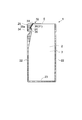
- a packaging bag in which the peripheral edges of two front and back packaging films as shown in FIG. 8 are sealed is advantageous.
- Such a refill packaging bag can be provided with a spout having an arbitrary width corresponding to the diameter of the container.
- the spout portion is formed by sealing the edge portions of the two front and back films, when the contents are poured out, the openings are pulled to both ends where the seals are sealed. For this reason, the front and back films are in a pseudo close contact state, the spout is closed, the spout is easily bent, and the spout is detached from the container that is repeatedly used during the refilling operation.
- Patent Document 2 In order to solve the problem that the spout is blocked or bent, a part different from the film is inserted into the spout (see Patent Document 2), or the film near the spout is inflated to form a three-dimensional shape Thus, many packaging bags that secure an opening area have been proposed (see Patent Document 3).
- packaging bags require a process of attaching another member, a process of deep embossing the film, and the like. Furthermore, the packaging bags cannot be neatly stacked and arranged in the packaging bag supply section at the time of filling. In addition, in the spout where the two front and back films are sealed, there are seal portions at both ends, so the opening width is narrowed by the amount of the seal portion, and a sufficient opening area cannot be secured. If a sufficient opening area cannot be secured, the time required for dispensing at the time of refilling will be long.
- FIG. 9A is a diagram showing the flexible packaging bag disclosed in Patent Document 5, and FIG. 9B is an enlarged view of the spout portion.
- a soft packaging bag is provided with a cut line a, a V-shaped cutout b, and a dot-like scratch processing c provided so as to cover the cut line a at the spout portion.
- the tear of the packaging bag is detached from the cut line a and cannot be opened at the original position of the cut line a.
- Patent Document 6 As shown in FIG. 10, an opening schedule line for forming a spout is formed so as to be inclined with respect to the bent portion. On the planned opening line, easy cut processing is performed to form a plurality of flaw lines parallel to the planned opening line. Furthermore, a refill container has been proposed that can easily and reliably open the spout by bending the tip of the opening cut line in a direction parallel to the planned opening line.
- a plurality of scratched lines provided in the bent portion may be rubbed or subjected to an impact, and the refill container may be damaged or a hole may be opened, causing liquid leakage.
- Japanese Unexamined Patent Publication No. 2004-99082 Japanese Patent Laid-Open No. 5-132069 Japanese Patent No. 4110940 Japanese Unexamined Patent Publication No. 11-236053 Japanese Patent No. 4910528 Japanese Unexamined Patent Publication No. 2011-255947
- the present invention has been made in consideration of the above points, and provides a refill container capable of forming a large-area spout without using a separate member such as a plug. Furthermore, the present invention provides a refill container that can easily and reliably open a spout, and can prevent liquid leakage due to rubbing or scratching during the distribution process and handling.
- 1st aspect of this invention is a refill container, Comprising: One laminated body which has a base material and a sealant layer, A pouring nozzle seal part, A laminated body so that a sealant layer may become an inner side Is bent to form a bent portion, a front surface laminate, and a back surface laminate, and the periphery of the front surface laminate and the back surface laminate is sealed, and the bent portion includes the front surface laminate, the back surface laminate, and the dispensing nozzle seal. And a dispensing nozzle that pours out the contents.
- the tip of the dispensing nozzle is sealed by the dispensing nozzle tip seal, and the dispensing nozzle tip seal is cut along the planned opening line. Easily cut to form a plurality of half-cut lines parallel to the planned opening line, and the plurality of half-cut lines are interrupted at the ridge line of the bent portion. Have .
- the cut portion of the half-cut line is provided in the bent portion, it is possible to prevent liquid leakage due to the bent portion being rubbed or torn.
- more than half of the plurality of half-cut lines are interrupted at the ridge line of the bent portion.
- the broken line and the unbroken line are alternately arranged in the bent portion.
- 4th aspect of this invention is a refill container, Comprising: One laminated body which has a base material and a sealant layer, A pouring nozzle seal part, A laminated body so that a sealant layer may become an inner side Is bent to form a bent portion, a front surface laminate, and a back surface laminate, and the periphery of the front surface laminate and the back surface laminate is sealed, and the bent portion includes the front surface laminate, the back surface laminate, and the dispensing nozzle.
- a pouring nozzle for pouring the contents is formed together with the seal portion, and the tip of the pouring nozzle is sealed by the pouring nozzle tip seal portion, and the pouring nozzle tip seal portion is cut along the planned opening line.
- An easy-cut process for forming an outlet and forming one half-cut line parallel to the planned opening line on the planned opening line is performed, and the half-cut line is interrupted at the ridge line of the bent portion.
- the half-cut line is interrupted in a range where the distance from the ridge line of the bent portion is 1.0 mm or greater and 4.0 mm or less.
- a bottom tape formed by bending the sealant layer further outward, and the bottom tape is a surface laminate and a back laminate. And a sealing portion having a sealed periphery, and a standing pouch shape.
- the seventh aspect of the present invention is a refill container according to the first to sixth aspects, further comprising a filling opening formed by cutting a part of the bent portion and filling the contents.
- the refill container is formed by bending a single laminate having at least a base material and a sealant layer so that the sealant layer is on the inside, a bent portion, and a surface laminate of the main body.
- the back laminate is formed and the periphery is sealed. Therefore, unlike a container using a plastic bottle or a plastic spigot, a refill container can be manufactured using only the flexible packaging laminate, and thus can be manufactured at low cost.
- a single laminate is folded so that the sealant layer is on the inside to form a bent portion, and the bent portion is a front laminate, a back laminate, and a dispensing nozzle seal. Together with the part, a pouring nozzle for pouring out the contents is formed. Therefore, it is possible to secure a large-area spout, and as a result, a smooth and quick refilling operation is possible. Also, the spout can be easily and reliably formed.
- ⁇ Easy-cut processing consisting of one or more half-cut lines parallel to the planned opening line is performed on or near the planned opening line. More than half of one half-cut line or a plurality of half-cut lines are interrupted when the distance from the ridge line of the bent portion is 1.0 mm or greater and 4.0 mm or less. Therefore, the half-cut line is interrupted at the bent portion, or the density of the half-cut line is reduced. For this reason, it can prevent that a laminated body is rubbed or torn in a bending part, and a liquid leak arises. Further, when the opening knob is pulled up, the tear of the laminate naturally proceeds along the planned opening line, and the spout can be easily formed at a predetermined position.
- the density of the half-cut lines is uniform. Therefore, it is possible to prevent liquid leakage and easily form an easy cut of the spout.
- the refill container is formed by bending a single laminate having at least a base material and a sealant layer so that the sealant layer is on the outside to form a bottom tape, It is a standing pouch shape which has the structure which inserts between a body and a back surface laminated body, and seals a periphery. Thereby, it becomes possible to form a large-capacity refill container having self-supporting properties.
- a part of the bent portion is cut open to form the filling opening for filling the contents.
- the pouring is performed after inserting the nozzle of the container to be used repeatedly into the pouring nozzle held horizontally.
- the refilling operation can be performed quickly. That is, in the refill container, the spout is naturally opened by the bent portion formed by bending one laminated body, so that the nozzle of the desired container can be easily inserted.
- the spout suitable for a nozzle can be formed by designing the dimension of a spout according to a nozzle. For this reason, after inserting the nozzle of the container to be repeatedly used into the pouring nozzle held horizontally, the refilling operation can be performed quickly by tilting so that the pouring nozzle becomes vertical.
- FIG. 2 is a schematic cross-sectional view showing a layer structure of a laminated body constituting a refill container in the X-X ′ cross section of FIG. 1. It is an enlarged view which shows the detail of the extraction nozzle part of FIG. It is a schematic diagram which shows the state which opened the bending part of FIG. It is an enlarged view which shows other embodiment of the extraction nozzle part. It is a schematic diagram which shows the state which opened the bending part of FIG. It is a schematic diagram which shows the refill container which concerns on other embodiment of this invention. It is a schematic diagram which shows an example of the conventional refill container. It is a schematic diagram which shows the flexible packaging bag described in patent document 5. FIG. It is an enlarged view which shows the detail of the extraction port in the flexible packaging bag of FIG. 9A. It is a schematic diagram which shows the refill container described in patent document 6.
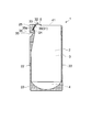
- FIG. 1 is a schematic view showing a refill container according to an embodiment of the present invention.
- FIG. 2 is a schematic cross-sectional view showing the layer structure of the laminated body constituting the refill container in the XX ′ cross section of FIG.
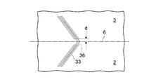
- FIG. 3 is an enlarged view showing details of the dispensing nozzle portion of FIG. 1
- FIG. 4 is a schematic view showing a state where the bent portion of FIG. 3 is opened.
- the refill container 1 includes a laminate having at least a base material 11 and a sealant layer 12 as shown in FIG. As shown in FIG. 1, this single laminate is folded so that the sealant layer 12 is inside to form a bent portion 6, a front surface laminate 2, and a back laminate 3. This is a refill container in which the peripheral edges of 2 and the back laminate 3 are sealed.
- the bending part 6 forms the pouring nozzle 32 which pours out the contents together with the front surface laminated body 2, the back surface laminated body 3, and the pouring nozzle seal part 24.
- the tip of the dispensing nozzle 32 is sealed by the dispensing nozzle tip seal portion 25.
- the spout 31 is formed when the spout nozzle tip seal 25 is cut along the planned opening line 36.
- the unscheduled opening line 36 is a single virtual line that starts from the opening cut line 35 and returns to the opening cut line via the front surface laminate 2, the bent portion 6, and the back surface laminate 3.
- an unsealing knob 34 that is separated and formed by an unsealing cut line 35 provided in the dispensing nozzle seal portion 24 is formed below the dispensing nozzle tip seal portion 25.
- a spout 31 (details are not shown) is formed by holding the unsealing knob 34 and cutting the spout nozzle tip seal portion 25 along the planned opening line 36.
- the planned opening line 36 is formed so as to be inclined with respect to the bent portion 6, and easy-cut processing 33 for forming a plurality of half-cut lines parallel to the planned opening line 36 is performed on and around the planned opening line. Has been.
- the leading end 35 a of the opening cut line 35 is bent in a direction parallel to the planned opening line 36. Further, the half cut line is interrupted at the bent portion 6.
- the refill container 1 is provided with an easy-cut process 33 for forming a plurality of half-cut lines parallel to the planned opening line 36 and its surroundings on the planned opening line 36 and its peripheral part. More than half of the half-cut lines are interrupted when the distance d from the ridge line of the bent portion 6 is in the range of 1.0 mm to 4.0 mm.
- the interrupted half-cut lines and uninterrupted half-cut lines are alternately arranged.
- the density of the half cut line in the bending part 6 becomes half or less.
- the bent portion 6 which is the uppermost part of the refill container 1 is prevented from being rubbed or torn due to a cause during transportation of the refill container 1 or a cause of its handling, thereby preventing liquid leakage. Can do.
- the distance d is suitably 1.0 mm or greater and 4.0 mm or less experimentally.
- FIG. 5 is an enlarged view showing another embodiment of the dispensing nozzle portion.
- FIG. 6 is a schematic diagram showing a state in which the bent portion of FIG. 5 is opened.
- one half-cut line is provided on the planned opening line 36, and the half-cut line is interrupted at the ridge line of the bent portion 6.
- the refill container 1 according to another embodiment of the present invention is subjected to the easy cutting process 33 for forming one or more half-cut lines parallel to the planned opening line 36. More than half of the half-cut lines (in this case, one) are interrupted when the distance d from the ridge line of the bent portion 6 is in the range of 1.0 mm to 4.0 mm.
- the bent portion 6 of the refill container 1 will be further described.
- the bent portion 6 is formed by bending the top portion of one laminate so that the sealant layer 12 is on the inside.
- the bent portion 6 forms an outflow path for the contents reaching the spout 31 together with the pouring nozzle seal portion 24 provided on the lower portion of the bent portion, the front surface laminate 2 and the back surface laminate 3. Due to the elastic action of the laminate in the bent portion 6, the cross section of the outflow channel is always in a shape with the upper portion swelled. For this reason, it becomes possible to keep the cross-sectional area of the spout 31 wide, and it becomes possible to discharge a large amount of contents at a time.
- the dispensing nozzle 34 is provided along the scheduled opening line 36 with the unsealing knob 34 separated and formed by the unsealing cut line 35 provided in the dispensing nozzle seal portion 24.
- the spout 31 is formed by cutting off the tip seal portion 25.
- the planned opening line 36 is formed so as to incline with respect to the bent portion 6, and easy-cut processing 33 for forming a plurality of half-cut lines parallel to the planned opening line 36 is performed on and around the planned opening line. Has been.
- the leading end 35 a of the opening cut line 35 is bent in a direction parallel to the planned opening line 36. Therefore, opening can be performed smoothly.
- the front surface laminate 2 and the back surface laminate 3 are sealed at the side seal portion 22 and the bottom seal portion 23 to form a bag shape.
- a filling opening for filling the contents is necessary, but it is not shown in FIG.
- a filling opening can be provided in the bottom seal portion 23 or the side seal portion 22.
- a part of the bent portion 6 can be cut open to form the filling opening 41.
- the filling nozzle 41 is inserted into the filling opening 41 to fill the contents.
- the end of the filling opening 41 on the dispensing nozzle side may be pulled and stretched. In order to prevent such elongation, it is preferable to provide a point seal at the end of the dispensing nozzle.
- the bent portion 6 is formed horizontally on the top of the refill container 1, but may be formed perpendicular to the side surface of the refill container.
- the scheduled opening line 36 is a virtual line indicating the opening position, but in order to clearly indicate the opening position, a print display or the like may be actually performed.
- the easy cut process 33 is a half-cut line provided on the outer surface of the front surface laminate 2 and the back surface laminate 3.
- a method of forming with a cutting tool and a method of forming by laser processing are generally used, but a more uniform and stable cut can be formed by a method using laser processing.
- a carbon dioxide laser is preferable.
- a laminate usually used for flexible packaging bags can be used.
- the base material 11 paper having one layer or several layers, metal foil, or a synthetic resin film is suitable.
- polyolefin resins such as low density polyethylene resin (LDPE), high density polyethylene resin (HDPE), linear low density polyethylene resin (LLDPE), polypropylene resin (PP), and polyolefin elastomers, polyethylene terephthalate resin ( PET), polyester resins such as polybutylene terephthalate resin (PBT), and polyethylene naphthalate resin (PEN), cellulose resins such as cellophane and cellulose triacetate (TAC), polymethyl methacrylate (PMMA) resin, ethylene -Vinyl acetate copolymer resin (EVA), ionomer resin, polybutene resin, polyacrylonitrile resin, polyamide resin, polystyrene resin (PS), polyvinyl chloride resin (PVC), poly Fluoride resin
- LDPE low density polyethylene resin
- paper high-quality paper, one-sided art paper, coated paper, cast coated paper, imitation paper, or the like can be used.
- the paper may crack due to deep embossing. Therefore, when using paper for the refill container according to the present embodiment, a laminate using paper can be stably used by forming streak-like embossing as convex embossing and concave embossing. . From the viewpoint of environmental consideration, it is preferable to use paper.
- a polyolefin resin is generally used. Specifically, low density polyethylene resin, medium density polyethylene resin, linear low density polyethylene resin, ethylene-based resins such as ethylene / vinyl acetate copolymer, and ethylene / ⁇ -olefin copolymer, homopolypropylene resin, propylene -Polypropylene resins such as ethylene random copolymer, propylene / ethylene block copolymer, and propylene / ⁇ -olefin copolymer are used. Moreover, you may use the multilayer film which compounded these resin.
- the laminated structure of the laminate include PET / printing layer / adhesive layer / stretched polyamide resin film (hereinafter abbreviated as ONY) / adhesive layer / LLDPE, laminated film in this order, ONY / adhesive layer / LLDPE, ONY / adhesive layer / ONY / adhesive layer / LLDPE, paper / LDPE / aluminum foil / LDPE, and paper / LDPE.
- ONY printing layer / adhesive layer / stretched polyamide resin film
- ONY adhesive layer / LLDPE
- ONY / adhesive layer / ONY / adhesive layer / LLDPE laminated film in this order
- ONY / adhesive layer / LLDPE ONY / adhesive layer / ONY / adhesive layer / LLDPE
- paper / LDPE / aluminum foil / LDPE paper / LDPE.
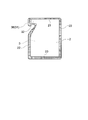
- FIG. 7 is a schematic view showing another embodiment of the refill container 1.
- a bottom tape 4 is formed by bending a single laminate having at least a base material and a sealant layer so that the sealant layer is on the outside, and the front laminate 2 and the back laminate. 3, and the peripheral edge is sealed to form a standing pouch shape.
- a part of the bent portion 6 is cut open to form the filling opening 41.
- the standing pouch-shaped container is a large-capacity container because the bottom tape 4 spreads. Therefore, it is possible to further shorten the dispensing time in the refill container.
- the bent portion 6 is formed by bending the top portion of one laminate so that the sealant layer is on the inside.
- the bent portion 6 forms an outflow path for the contents reaching the spout 31 together with the front surface laminate 2, the back surface laminate 3, and the spout nozzle seal portion 24. Thereby, especially when the contents are liquid, when the contents are poured out, the contents smoothly flow through the linear outflow path, so that the contents can be quickly poured out.
- the above configuration is more preferable in the present embodiment because the container of the present embodiment has a large capacity configuration.
- the top of the laminate that is slit to a width approximately twice the width corresponding to the height of the container is folded so that the surface of the sealant layer faces inside.
- the front surface laminate 2 and the back surface laminate 3 are formed.
- the front surface laminate 2 and the back surface laminate 3 are continuously supplied, and the bottom tape 4 folded in half so that the surface of the sealant layer is on the outside is continuously supplied therebetween. Furthermore, after performing necessary sealing, it is punched out to form a container.
- the refill container according to the present embodiment can ensure a large-area spout without using a special plastic spigot or the like. Moreover, since the size of the spout can be freely designed according to the desired shape of the stopper in the repetitively used container, it is useful as a dedicated refill container that can quickly perform a refill operation. .
- the refill container which concerns on this embodiment is demonstrated more concretely.
- a standing pouch having the shape shown in FIG. 7 was produced.
- the pouch size was 130 mm wide, 260 mm high, and 35 mm long folded.
- the width of the opening is about 18 mm.
- a part of the bent portion was cut to form a filling opening.
- easy-cut processing for forming a plurality of half-cut lines by laser processing as shown in FIGS. 3 and 4 was performed on the planned opening line that forms the spout at the tip of the spout nozzle.
- the distance d was 2 mm.
- An opening cutting line was formed in the dispensing nozzle seal portion, and the tip of the opening cutting line was bent so as to be parallel to the planned opening line.
Landscapes
- Engineering & Computer Science (AREA)
- Mechanical Engineering (AREA)
- Bag Frames (AREA)
- Packages (AREA)
- Cartons (AREA)
Priority Applications (6)
| Application Number | Priority Date | Filing Date | Title |
|---|---|---|---|
| CN201380051591.9A CN104684819B (zh) | 2012-10-03 | 2013-10-02 | 替换装容器 |
| KR1020157008562A KR102141539B1 (ko) | 2012-10-03 | 2013-10-02 | 리필 용기 |
| JP2014539786A JP6484901B2 (ja) | 2012-10-03 | 2013-10-02 | 詰替え容器 |
| EP13843599.5A EP2905238B1 (en) | 2012-10-03 | 2013-10-02 | Refillable container |
| IN2420DEN2015 IN2015DN02420A (https=) | 2012-10-03 | 2013-10-02 | |
| US14/671,175 US10040609B2 (en) | 2012-10-03 | 2015-03-27 | Refill container |
Applications Claiming Priority (2)
| Application Number | Priority Date | Filing Date | Title |
|---|---|---|---|
| JP2012-221167 | 2012-10-03 | ||
| JP2012221167 | 2012-10-03 |
Related Child Applications (1)
| Application Number | Title | Priority Date | Filing Date |
|---|---|---|---|
| US14/671,175 Continuation US10040609B2 (en) | 2012-10-03 | 2015-03-27 | Refill container |
Publications (1)
| Publication Number | Publication Date |
|---|---|
| WO2014054694A1 true WO2014054694A1 (ja) | 2014-04-10 |
Family
ID=50435015
Family Applications (1)
| Application Number | Title | Priority Date | Filing Date |
|---|---|---|---|
| PCT/JP2013/076827 Ceased WO2014054694A1 (ja) | 2012-10-03 | 2013-10-02 | 詰替え容器 |
Country Status (9)
| Country | Link |
|---|---|
| US (1) | US10040609B2 (https=) |
| EP (1) | EP2905238B1 (https=) |
| JP (2) | JP6484901B2 (https=) |
| KR (1) | KR102141539B1 (https=) |
| CN (1) | CN104684819B (https=) |
| IN (1) | IN2015DN02420A (https=) |
| MY (1) | MY177322A (https=) |
| TW (1) | TWI602752B (https=) |
| WO (1) | WO2014054694A1 (https=) |
Families Citing this family (5)
| Publication number | Priority date | Publication date | Assignee | Title |
|---|---|---|---|---|
| JP5975452B2 (ja) * | 2014-07-08 | 2016-08-23 | 株式会社悠心 | 包装袋 |
| BR112019008040B1 (pt) * | 2016-10-21 | 2023-02-23 | Mark Steele | Embalagem de controle de conteúdo |
| FR3061155B1 (fr) * | 2016-12-28 | 2019-05-31 | Andros | Emballage pour le conditionnement d'un produit, notamment alimentaire |
| US11873159B2 (en) | 2020-08-19 | 2024-01-16 | Mark Steele | Package having a hingeable valve mechanism |
| FR3129928B1 (fr) * | 2021-12-03 | 2024-06-21 | Oreal | Sachet souple à double ouverture |
Citations (10)
| Publication number | Priority date | Publication date | Assignee | Title |
|---|---|---|---|---|
| JPH04327139A (ja) * | 1991-04-22 | 1992-11-16 | Taisei Ramick Kk | 易開封性包装袋 |
| JPH05132069A (ja) | 1991-05-16 | 1993-05-28 | Cellpack Ag | 袋及びその製造方法 |
| JPH11236053A (ja) | 1998-02-20 | 1999-08-31 | Kanebo Ltd | 詰め替え用袋 |
| JP2003327255A (ja) * | 2002-05-02 | 2003-11-19 | Toyo Seikan Kaisha Ltd | 易開封パウチ |
| JP2004099082A (ja) | 2002-09-06 | 2004-04-02 | Toyo Seikan Kaisha Ltd | 手放し詰め替え容器 |
| JP4110940B2 (ja) | 2002-11-18 | 2008-07-02 | 凸版印刷株式会社 | ノズル付き液体収納容器 |
| JP2011255946A (ja) * | 2010-06-11 | 2011-12-22 | Toppan Printing Co Ltd | 詰替え容器 |
| JP2011255947A (ja) | 2010-06-11 | 2011-12-22 | Toppan Printing Co Ltd | 詰替え容器 |
| JP4910528B2 (ja) | 2006-07-14 | 2012-04-04 | 凸版印刷株式会社 | 軟質包装袋 |
| JP2012176782A (ja) * | 2011-02-28 | 2012-09-13 | Fuji Seal International Inc | パウチ容器 |
Family Cites Families (58)
| Publication number | Priority date | Publication date | Assignee | Title |
|---|---|---|---|---|
| USRE24251E (en) * | 1956-12-04 | Dispensing containers for liquids | ||
| US2093974A (en) * | 1934-09-22 | 1937-09-21 | John A Farmer | Package or container |
| US2105798A (en) * | 1934-10-23 | 1938-01-18 | Tobiasson Anders Fredrik | Vessel or box for canning |
| US2707581A (en) * | 1954-12-07 | 1955-05-03 | Kaplan Yale | Dispensing containers for liquids |
| US2811281A (en) * | 1955-01-18 | 1957-10-29 | Donovan Marion | Dispensing container for flowable material |
| GB1015383A (en) * | 1963-10-03 | 1965-12-31 | Arenco Ab | Improvements in or relating to easily openable bags |
| US3341108A (en) * | 1964-01-20 | 1967-09-12 | Quaker Oats Co | Easy opening bag |
| US3278085A (en) * | 1964-06-02 | 1966-10-11 | Brown Royce Edward | Re-sealable sachet container |
| US3412918A (en) * | 1966-10-31 | 1968-11-26 | Phillips Petroleum Co | Dispensing container |
| JPS4910528B1 (https=) | 1969-02-07 | 1974-03-11 | ||
| GB1355036A (en) * | 1970-04-14 | 1974-06-05 | Ici Ltd | Articles of plastic film |
| US3873018A (en) * | 1973-02-20 | 1975-03-25 | Minnesota Mining & Mfg | Easily rupturable band of tape |
| US4491245A (en) * | 1982-03-24 | 1985-01-01 | Jamison Mark D | Liquid dispensing container |
| US4691834A (en) * | 1982-07-12 | 1987-09-08 | Bankers Trust Company | Cap and neck structure for a wide mouth jar |
| US4437593A (en) * | 1982-07-12 | 1984-03-20 | Three Sisters Ranch Enterprises | Overcap for spice canister |
| US4650079A (en) * | 1983-02-08 | 1987-03-17 | Kazuhiro Itoh | Easy-to-open synthetic resin bag and apparatus for the manufacture thereof |
| US4732275A (en) * | 1987-06-26 | 1988-03-22 | International Paper Company | Openable and reclosable carton |
| US4844268A (en) * | 1987-09-25 | 1989-07-04 | Cap Snap Co. | Tamper-evident cap and neck structure |
| US4815617A (en) * | 1988-05-12 | 1989-03-28 | Cap Snap Co. | Tamper-evident container cap having sealed disc retention means |
| US5018646A (en) * | 1988-11-23 | 1991-05-28 | S. C. Johnson & Son, Inc. | Squeezable fluid container |
| US4998646A (en) * | 1989-03-23 | 1991-03-12 | Colgate-Palmolive Co. | Flexible pouch contoured to facilitate pouring |
| US4911316A (en) * | 1989-04-27 | 1990-03-27 | Cap Snap Co. | Plastic bottle cap sealing plural neck profiles |
| US5241150A (en) * | 1989-10-02 | 1993-08-31 | Minnesota Mining And Manufacturing Company | Microwave food package |
| US4974732A (en) * | 1990-02-02 | 1990-12-04 | S. C. Johnson & Son, Inc. | Sealed pouch having tear-open spout |
| US4978232A (en) * | 1990-02-12 | 1990-12-18 | Colgate-Palmolive Co. | Flexible pouch with folded spout |
| US5411178A (en) * | 1994-03-11 | 1995-05-02 | Beeton Holdings Limited | Fluid dispenser pouch with venturi shaped outlet |
| JP3006944U (ja) * | 1994-07-20 | 1995-01-31 | 味の素株式会社 | スタンディングパウチ |
| US5839609A (en) * | 1997-08-27 | 1998-11-24 | Colgate-Palmolive Company | Thermoformed pack with ridge valve |
| US6667081B1 (en) * | 1998-06-19 | 2003-12-23 | Dai Nippon Printing Co., Ltd. | Pouch and method of producing film for pouch |
| US6244467B1 (en) * | 1998-07-27 | 2001-06-12 | Benjamin Lewit | Material container and dispenser having a litterless closure |
| US6209754B1 (en) * | 1998-10-27 | 2001-04-03 | Kao Corporation | Pouch |
| US6360513B1 (en) * | 1999-05-11 | 2002-03-26 | Sargento Foods Inc. | Resealable bag for filling with food product(s) and method |
| US6783030B2 (en) * | 1999-11-19 | 2004-08-31 | Sanford Redmond | Easy opening sealed containment and dispensing package |
| US6863178B2 (en) * | 2000-12-05 | 2005-03-08 | Daisy Brand, Inc. | Packet container |
| DK1466831T3 (da) * | 2001-12-18 | 2008-06-02 | Idemitsu Unitech Co Ltd | Forseglet pose med oprivningstrimmel |
| KR100969859B1 (ko) * | 2003-03-17 | 2010-07-13 | 가부시키가이샤 호소카와 요코 | 파스너 백 |
| GB2418911B (en) * | 2003-07-15 | 2007-07-18 | Procter & Gamble | Container refilling system |
| JP4828413B2 (ja) * | 2004-04-19 | 2011-11-30 | 株式会社フジシールインターナショナル | パウチ及びスパウト付きパウチ容器 |
| ES2415382T3 (es) * | 2004-07-30 | 2013-07-25 | Yushin Co., Ltd. | Boquilla de vertido de líquido con una bolsa de envasado |
| JP5028762B2 (ja) * | 2005-07-20 | 2012-09-19 | 東洋製罐株式会社 | 詰替パウチ |
| CN101238040B (zh) * | 2005-08-11 | 2011-01-26 | 大日本印刷株式会社 | 带有注出口部的袋子 |
| US20080233252A1 (en) * | 2005-10-27 | 2008-09-25 | Manning Paul B | Containers and Methods for the Reconstitution and Dispensation of Concentrated or Powdered Products |
| JP2009524564A (ja) * | 2006-01-27 | 2009-07-02 | ザ プロクター アンド ギャンブル カンパニー | 顆粒貯蔵用パウチ |
| JP5082279B2 (ja) * | 2006-04-07 | 2012-11-28 | 東洋製罐株式会社 | パウチ容器 |
| JP2008081144A (ja) * | 2006-09-26 | 2008-04-10 | Meiwa Pax Co Ltd | 詰め替え用包装袋 |
| SE0700769L (sv) * | 2007-03-28 | 2008-09-29 | Ecolean Res & Dev As | Rivanvisning |
| US20080253700A1 (en) * | 2007-04-16 | 2008-10-16 | Ting-Jen Sh | Refill pack |
| JP5315647B2 (ja) * | 2007-08-31 | 2013-10-16 | 凸版印刷株式会社 | パウチ容器 |
| CN101327866A (zh) * | 2007-12-24 | 2008-12-24 | 赵忠华 | 一种方便回收的易撕环保包装袋 |
| US20140061235A1 (en) * | 2008-08-14 | 2014-03-06 | Vladimir Ankudinov | Package for paste-like products |
| DE202009000302U1 (de) * | 2009-01-10 | 2009-03-19 | Nordenia Deutschland Halle Gmbh | Folienverpackung |
| JP5702056B2 (ja) * | 2009-06-19 | 2015-04-15 | 凸版印刷株式会社 | 詰替え容器 |
| WO2011037717A1 (en) * | 2009-09-25 | 2011-03-31 | The Procter & Gamble Company | Reclosable package |
| MY173929A (en) * | 2010-12-28 | 2020-02-27 | Abbott Lab | Pouch, method of manufacturing a pouch and a method of dispensing a product from a pouch |
| EP2471724B1 (de) * | 2010-12-29 | 2017-04-19 | Mondi Halle GmbH | Verwendung eines flachgelegten folienbeutels in automatischen abfüllanlagen |
| WO2012091674A1 (en) * | 2010-12-30 | 2012-07-05 | Nestec S.A. | Pressure operated dispensing device |
| US10081473B2 (en) * | 2011-04-08 | 2018-09-25 | Ampac Holdings, Llc | Packaging container with pull tab |
| US8720749B1 (en) * | 2012-05-31 | 2014-05-13 | Louis Greco | Portable mouthwash carrying device |
-
2013
- 2013-10-02 CN CN201380051591.9A patent/CN104684819B/zh active Active
- 2013-10-02 IN IN2420DEN2015 patent/IN2015DN02420A/en unknown
- 2013-10-02 KR KR1020157008562A patent/KR102141539B1/ko not_active Expired - Fee Related
- 2013-10-02 MY MYPI2015700937A patent/MY177322A/en unknown
- 2013-10-02 WO PCT/JP2013/076827 patent/WO2014054694A1/ja not_active Ceased
- 2013-10-02 JP JP2014539786A patent/JP6484901B2/ja active Active
- 2013-10-02 EP EP13843599.5A patent/EP2905238B1/en active Active
- 2013-10-03 TW TW102135785A patent/TWI602752B/zh not_active IP Right Cessation
-
2015
- 2015-03-27 US US14/671,175 patent/US10040609B2/en active Active
-
2018
- 2018-01-31 JP JP2018015892A patent/JP6516027B2/ja active Active
Patent Citations (10)
| Publication number | Priority date | Publication date | Assignee | Title |
|---|---|---|---|---|
| JPH04327139A (ja) * | 1991-04-22 | 1992-11-16 | Taisei Ramick Kk | 易開封性包装袋 |
| JPH05132069A (ja) | 1991-05-16 | 1993-05-28 | Cellpack Ag | 袋及びその製造方法 |
| JPH11236053A (ja) | 1998-02-20 | 1999-08-31 | Kanebo Ltd | 詰め替え用袋 |
| JP2003327255A (ja) * | 2002-05-02 | 2003-11-19 | Toyo Seikan Kaisha Ltd | 易開封パウチ |
| JP2004099082A (ja) | 2002-09-06 | 2004-04-02 | Toyo Seikan Kaisha Ltd | 手放し詰め替え容器 |
| JP4110940B2 (ja) | 2002-11-18 | 2008-07-02 | 凸版印刷株式会社 | ノズル付き液体収納容器 |
| JP4910528B2 (ja) | 2006-07-14 | 2012-04-04 | 凸版印刷株式会社 | 軟質包装袋 |
| JP2011255946A (ja) * | 2010-06-11 | 2011-12-22 | Toppan Printing Co Ltd | 詰替え容器 |
| JP2011255947A (ja) | 2010-06-11 | 2011-12-22 | Toppan Printing Co Ltd | 詰替え容器 |
| JP2012176782A (ja) * | 2011-02-28 | 2012-09-13 | Fuji Seal International Inc | パウチ容器 |
Non-Patent Citations (1)
| Title |
|---|
| See also references of EP2905238A4 |
Also Published As
| Publication number | Publication date |
|---|---|
| CN104684819A (zh) | 2015-06-03 |
| EP2905238A1 (en) | 2015-08-12 |
| US20150197379A1 (en) | 2015-07-16 |
| KR20150066529A (ko) | 2015-06-16 |
| CN104684819B (zh) | 2017-08-22 |
| EP2905238B1 (en) | 2018-12-12 |
| KR102141539B1 (ko) | 2020-08-05 |
| MY177322A (en) | 2020-09-11 |
| JPWO2014054694A1 (ja) | 2016-08-25 |
| EP2905238A4 (en) | 2016-04-13 |
| IN2015DN02420A (https=) | 2015-09-04 |
| TWI602752B (zh) | 2017-10-21 |
| JP2018065624A (ja) | 2018-04-26 |
| US10040609B2 (en) | 2018-08-07 |
| JP6516027B2 (ja) | 2019-05-22 |
| TW201425158A (zh) | 2014-07-01 |
| JP6484901B2 (ja) | 2019-03-20 |
Similar Documents
| Publication | Publication Date | Title |
|---|---|---|
| JP2018065624A (ja) | 詰替え容器 | |
| JP5699458B2 (ja) | 詰替え容器 | |
| JP5633201B2 (ja) | 詰替え容器 | |
| JP5702056B2 (ja) | 詰替え容器 | |
| JP5789969B2 (ja) | 詰替え容器 | |
| JP5573245B2 (ja) | 詰替え容器 | |
| JP5516121B2 (ja) | 詰替え容器およびその製造方法 | |
| JP5927861B2 (ja) | 詰替え容器 | |
| JP5782748B2 (ja) | 詰替え容器 | |
| JP6186823B2 (ja) | 詰替え容器 | |
| JP5573186B2 (ja) | 詰替え容器 | |
| JP6586798B2 (ja) | 収納容器 | |
| JP6111640B2 (ja) | 詰替え容器の製造方法 | |
| JP5644066B2 (ja) | 詰替え容器 | |
| JP5573165B2 (ja) | 詰替え容器 | |
| JP6127577B2 (ja) | 詰替え容器 | |
| JP6291869B2 (ja) | 詰替え容器 | |
| JP6011057B2 (ja) | 詰替え容器 | |
| JP6146046B2 (ja) | 詰替え容器 | |
| JP2013067418A (ja) | 詰替え容器 | |
| JP2011037461A (ja) | 詰替え容器 |
Legal Events
| Date | Code | Title | Description |
|---|---|---|---|
| 121 | Ep: the epo has been informed by wipo that ep was designated in this application |
Ref document number: 13843599 Country of ref document: EP Kind code of ref document: A1 |
|
| WWE | Wipo information: entry into national phase |
Ref document number: 2013843599 Country of ref document: EP |
|
| ENP | Entry into the national phase |
Ref document number: 2014539786 Country of ref document: JP Kind code of ref document: A |
|
| ENP | Entry into the national phase |
Ref document number: 20157008562 Country of ref document: KR Kind code of ref document: A |
|
| NENP | Non-entry into the national phase |
Ref country code: DE |
|
| WWE | Wipo information: entry into national phase |
Ref document number: IDP00201502236 Country of ref document: ID |