WO2014054501A1 - 気相成長装置 - Google Patents
気相成長装置 Download PDFInfo
- Publication number
- WO2014054501A1 WO2014054501A1 PCT/JP2013/076091 JP2013076091W WO2014054501A1 WO 2014054501 A1 WO2014054501 A1 WO 2014054501A1 JP 2013076091 W JP2013076091 W JP 2013076091W WO 2014054501 A1 WO2014054501 A1 WO 2014054501A1
- Authority
- WO
- WIPO (PCT)
- Prior art keywords
- susceptor
- cover
- ceiling plate
- push
- temporary placement
- Prior art date
- Legal status (The legal status is an assumption and is not a legal conclusion. Google has not performed a legal analysis and makes no representation as to the accuracy of the status listed.)
- Ceased
Links
Images











Classifications
-
- C—CHEMISTRY; METALLURGY
- C23—COATING METALLIC MATERIAL; COATING MATERIAL WITH METALLIC MATERIAL; CHEMICAL SURFACE TREATMENT; DIFFUSION TREATMENT OF METALLIC MATERIAL; COATING BY VACUUM EVAPORATION, BY SPUTTERING, BY ION IMPLANTATION OR BY CHEMICAL VAPOUR DEPOSITION, IN GENERAL; INHIBITING CORROSION OF METALLIC MATERIAL OR INCRUSTATION IN GENERAL
- C23C—COATING METALLIC MATERIAL; COATING MATERIAL WITH METALLIC MATERIAL; SURFACE TREATMENT OF METALLIC MATERIAL BY DIFFUSION INTO THE SURFACE, BY CHEMICAL CONVERSION OR SUBSTITUTION; COATING BY VACUUM EVAPORATION, BY SPUTTERING, BY ION IMPLANTATION OR BY CHEMICAL VAPOUR DEPOSITION, IN GENERAL
- C23C16/00—Chemical coating by decomposition of gaseous compounds, without leaving reaction products of surface material in the coating, i.e. chemical vapour deposition [CVD] processes
- C23C16/44—Chemical coating by decomposition of gaseous compounds, without leaving reaction products of surface material in the coating, i.e. chemical vapour deposition [CVD] processes characterised by the method of coating
- C23C16/458—Chemical coating by decomposition of gaseous compounds, without leaving reaction products of surface material in the coating, i.e. chemical vapour deposition [CVD] processes characterised by the method of coating characterised by the method used for supporting substrates in the reaction chamber
- C23C16/4582—Rigid and flat substrates, e.g. plates or discs
- C23C16/4583—Rigid and flat substrates, e.g. plates or discs the substrate being supported substantially horizontally
-
- C—CHEMISTRY; METALLURGY
- C23—COATING METALLIC MATERIAL; COATING MATERIAL WITH METALLIC MATERIAL; CHEMICAL SURFACE TREATMENT; DIFFUSION TREATMENT OF METALLIC MATERIAL; COATING BY VACUUM EVAPORATION, BY SPUTTERING, BY ION IMPLANTATION OR BY CHEMICAL VAPOUR DEPOSITION, IN GENERAL; INHIBITING CORROSION OF METALLIC MATERIAL OR INCRUSTATION IN GENERAL
- C23C—COATING METALLIC MATERIAL; COATING MATERIAL WITH METALLIC MATERIAL; SURFACE TREATMENT OF METALLIC MATERIAL BY DIFFUSION INTO THE SURFACE, BY CHEMICAL CONVERSION OR SUBSTITUTION; COATING BY VACUUM EVAPORATION, BY SPUTTERING, BY ION IMPLANTATION OR BY CHEMICAL VAPOUR DEPOSITION, IN GENERAL
- C23C16/00—Chemical coating by decomposition of gaseous compounds, without leaving reaction products of surface material in the coating, i.e. chemical vapour deposition [CVD] processes
- C23C16/44—Chemical coating by decomposition of gaseous compounds, without leaving reaction products of surface material in the coating, i.e. chemical vapour deposition [CVD] processes characterised by the method of coating
-
- C—CHEMISTRY; METALLURGY
- C23—COATING METALLIC MATERIAL; COATING MATERIAL WITH METALLIC MATERIAL; CHEMICAL SURFACE TREATMENT; DIFFUSION TREATMENT OF METALLIC MATERIAL; COATING BY VACUUM EVAPORATION, BY SPUTTERING, BY ION IMPLANTATION OR BY CHEMICAL VAPOUR DEPOSITION, IN GENERAL; INHIBITING CORROSION OF METALLIC MATERIAL OR INCRUSTATION IN GENERAL
- C23C—COATING METALLIC MATERIAL; COATING MATERIAL WITH METALLIC MATERIAL; SURFACE TREATMENT OF METALLIC MATERIAL BY DIFFUSION INTO THE SURFACE, BY CHEMICAL CONVERSION OR SUBSTITUTION; COATING BY VACUUM EVAPORATION, BY SPUTTERING, BY ION IMPLANTATION OR BY CHEMICAL VAPOUR DEPOSITION, IN GENERAL
- C23C16/00—Chemical coating by decomposition of gaseous compounds, without leaving reaction products of surface material in the coating, i.e. chemical vapour deposition [CVD] processes
- C23C16/44—Chemical coating by decomposition of gaseous compounds, without leaving reaction products of surface material in the coating, i.e. chemical vapour deposition [CVD] processes characterised by the method of coating
- C23C16/458—Chemical coating by decomposition of gaseous compounds, without leaving reaction products of surface material in the coating, i.e. chemical vapour deposition [CVD] processes characterised by the method of coating characterised by the method used for supporting substrates in the reaction chamber
- C23C16/4582—Rigid and flat substrates, e.g. plates or discs
- C23C16/4583—Rigid and flat substrates, e.g. plates or discs the substrate being supported substantially horizontally
- C23C16/4584—Rigid and flat substrates, e.g. plates or discs the substrate being supported substantially horizontally the substrate being rotated
-
- C—CHEMISTRY; METALLURGY
- C23—COATING METALLIC MATERIAL; COATING MATERIAL WITH METALLIC MATERIAL; CHEMICAL SURFACE TREATMENT; DIFFUSION TREATMENT OF METALLIC MATERIAL; COATING BY VACUUM EVAPORATION, BY SPUTTERING, BY ION IMPLANTATION OR BY CHEMICAL VAPOUR DEPOSITION, IN GENERAL; INHIBITING CORROSION OF METALLIC MATERIAL OR INCRUSTATION IN GENERAL
- C23C—COATING METALLIC MATERIAL; COATING MATERIAL WITH METALLIC MATERIAL; SURFACE TREATMENT OF METALLIC MATERIAL BY DIFFUSION INTO THE SURFACE, BY CHEMICAL CONVERSION OR SUBSTITUTION; COATING BY VACUUM EVAPORATION, BY SPUTTERING, BY ION IMPLANTATION OR BY CHEMICAL VAPOUR DEPOSITION, IN GENERAL
- C23C16/00—Chemical coating by decomposition of gaseous compounds, without leaving reaction products of surface material in the coating, i.e. chemical vapour deposition [CVD] processes
- C23C16/44—Chemical coating by decomposition of gaseous compounds, without leaving reaction products of surface material in the coating, i.e. chemical vapour deposition [CVD] processes characterised by the method of coating
- C23C16/458—Chemical coating by decomposition of gaseous compounds, without leaving reaction products of surface material in the coating, i.e. chemical vapour deposition [CVD] processes characterised by the method of coating characterised by the method used for supporting substrates in the reaction chamber
- C23C16/4582—Rigid and flat substrates, e.g. plates or discs
- C23C16/4583—Rigid and flat substrates, e.g. plates or discs the substrate being supported substantially horizontally
- C23C16/4585—Devices at or outside the perimeter of the substrate support, e.g. clamping rings, shrouds
-
- C—CHEMISTRY; METALLURGY
- C23—COATING METALLIC MATERIAL; COATING MATERIAL WITH METALLIC MATERIAL; CHEMICAL SURFACE TREATMENT; DIFFUSION TREATMENT OF METALLIC MATERIAL; COATING BY VACUUM EVAPORATION, BY SPUTTERING, BY ION IMPLANTATION OR BY CHEMICAL VAPOUR DEPOSITION, IN GENERAL; INHIBITING CORROSION OF METALLIC MATERIAL OR INCRUSTATION IN GENERAL
- C23C—COATING METALLIC MATERIAL; COATING MATERIAL WITH METALLIC MATERIAL; SURFACE TREATMENT OF METALLIC MATERIAL BY DIFFUSION INTO THE SURFACE, BY CHEMICAL CONVERSION OR SUBSTITUTION; COATING BY VACUUM EVAPORATION, BY SPUTTERING, BY ION IMPLANTATION OR BY CHEMICAL VAPOUR DEPOSITION, IN GENERAL
- C23C16/00—Chemical coating by decomposition of gaseous compounds, without leaving reaction products of surface material in the coating, i.e. chemical vapour deposition [CVD] processes
- C23C16/44—Chemical coating by decomposition of gaseous compounds, without leaving reaction products of surface material in the coating, i.e. chemical vapour deposition [CVD] processes characterised by the method of coating
- C23C16/52—Controlling or regulating the coating process
-
- H—ELECTRICITY
- H10—SEMICONDUCTOR DEVICES; ELECTRIC SOLID-STATE DEVICES NOT OTHERWISE PROVIDED FOR
- H10P—GENERIC PROCESSES OR APPARATUS FOR THE MANUFACTURE OR TREATMENT OF DEVICES COVERED BY CLASS H10
- H10P72/00—Handling or holding of wafers, substrates or devices during manufacture or treatment thereof
- H10P72/04—Apparatus for manufacture or treatment
- H10P72/0451—Apparatus for manufacturing or treating in a plurality of work-stations
- H10P72/0462—Apparatus for manufacturing or treating in a plurality of work-stations characterised by the construction of the processing chambers, e.g. modular processing chambers
-
- H—ELECTRICITY
- H10—SEMICONDUCTOR DEVICES; ELECTRIC SOLID-STATE DEVICES NOT OTHERWISE PROVIDED FOR
- H10P—GENERIC PROCESSES OR APPARATUS FOR THE MANUFACTURE OR TREATMENT OF DEVICES COVERED BY CLASS H10
- H10P72/00—Handling or holding of wafers, substrates or devices during manufacture or treatment thereof
- H10P72/30—Handling or holding of wafers, substrates or devices during manufacture or treatment thereof for conveying, e.g. between different workstations
- H10P72/33—Handling or holding of wafers, substrates or devices during manufacture or treatment thereof for conveying, e.g. between different workstations into and out of processing chamber
- H10P72/3311—Horizontal transfer of a batch of workpieces
-
- H—ELECTRICITY
- H10—SEMICONDUCTOR DEVICES; ELECTRIC SOLID-STATE DEVICES NOT OTHERWISE PROVIDED FOR
- H10P—GENERIC PROCESSES OR APPARATUS FOR THE MANUFACTURE OR TREATMENT OF DEVICES COVERED BY CLASS H10
- H10P72/00—Handling or holding of wafers, substrates or devices during manufacture or treatment thereof
- H10P72/70—Handling or holding of wafers, substrates or devices during manufacture or treatment thereof for supporting or gripping
- H10P72/76—Handling or holding of wafers, substrates or devices during manufacture or treatment thereof for supporting or gripping using mechanical means, e.g. clamps or pinches
- H10P72/7604—Handling or holding of wafers, substrates or devices during manufacture or treatment thereof for supporting or gripping using mechanical means, e.g. clamps or pinches the wafers being placed on a susceptor, stage or support
- H10P72/7612—Handling or holding of wafers, substrates or devices during manufacture or treatment thereof for supporting or gripping using mechanical means, e.g. clamps or pinches the wafers being placed on a susceptor, stage or support characterised by lifting arrangements, e.g. lift pins
-
- H—ELECTRICITY
- H10—SEMICONDUCTOR DEVICES; ELECTRIC SOLID-STATE DEVICES NOT OTHERWISE PROVIDED FOR
- H10P—GENERIC PROCESSES OR APPARATUS FOR THE MANUFACTURE OR TREATMENT OF DEVICES COVERED BY CLASS H10
- H10P72/00—Handling or holding of wafers, substrates or devices during manufacture or treatment thereof
- H10P72/70—Handling or holding of wafers, substrates or devices during manufacture or treatment thereof for supporting or gripping
- H10P72/76—Handling or holding of wafers, substrates or devices during manufacture or treatment thereof for supporting or gripping using mechanical means, e.g. clamps or pinches
- H10P72/7604—Handling or holding of wafers, substrates or devices during manufacture or treatment thereof for supporting or gripping using mechanical means, e.g. clamps or pinches the wafers being placed on a susceptor, stage or support
- H10P72/7618—Handling or holding of wafers, substrates or devices during manufacture or treatment thereof for supporting or gripping using mechanical means, e.g. clamps or pinches the wafers being placed on a susceptor, stage or support characterised by a movable susceptor, stage or support, others than those only rotating on their own vertical axis, e.g. susceptors on a rotating carrousel
-
- H—ELECTRICITY
- H10—SEMICONDUCTOR DEVICES; ELECTRIC SOLID-STATE DEVICES NOT OTHERWISE PROVIDED FOR
- H10P—GENERIC PROCESSES OR APPARATUS FOR THE MANUFACTURE OR TREATMENT OF DEVICES COVERED BY CLASS H10
- H10P72/00—Handling or holding of wafers, substrates or devices during manufacture or treatment thereof
- H10P72/70—Handling or holding of wafers, substrates or devices during manufacture or treatment thereof for supporting or gripping
- H10P72/76—Handling or holding of wafers, substrates or devices during manufacture or treatment thereof for supporting or gripping using mechanical means, e.g. clamps or pinches
- H10P72/7604—Handling or holding of wafers, substrates or devices during manufacture or treatment thereof for supporting or gripping using mechanical means, e.g. clamps or pinches the wafers being placed on a susceptor, stage or support
- H10P72/7621—Handling or holding of wafers, substrates or devices during manufacture or treatment thereof for supporting or gripping using mechanical means, e.g. clamps or pinches the wafers being placed on a susceptor, stage or support characterised by supporting two or more semiconductor substrates
-
- H—ELECTRICITY
- H10—SEMICONDUCTOR DEVICES; ELECTRIC SOLID-STATE DEVICES NOT OTHERWISE PROVIDED FOR
- H10P—GENERIC PROCESSES OR APPARATUS FOR THE MANUFACTURE OR TREATMENT OF DEVICES COVERED BY CLASS H10
- H10P72/00—Handling or holding of wafers, substrates or devices during manufacture or treatment thereof
- H10P72/70—Handling or holding of wafers, substrates or devices during manufacture or treatment thereof for supporting or gripping
- H10P72/76—Handling or holding of wafers, substrates or devices during manufacture or treatment thereof for supporting or gripping using mechanical means, e.g. clamps or pinches
- H10P72/7604—Handling or holding of wafers, substrates or devices during manufacture or treatment thereof for supporting or gripping using mechanical means, e.g. clamps or pinches the wafers being placed on a susceptor, stage or support
- H10P72/7626—Handling or holding of wafers, substrates or devices during manufacture or treatment thereof for supporting or gripping using mechanical means, e.g. clamps or pinches the wafers being placed on a susceptor, stage or support characterised by the construction of the shaft
Definitions
- the present invention relates to a vapor phase growth apparatus for supplying a source gas onto a substrate installed in a reaction furnace to grow a thin film on the substrate.
- the vapor phase growth method is a thin film forming method in which a thin film raw material is supplied in a gas state onto a substrate, and the raw material is deposited on the substrate surface by a chemical reaction.
- a gallium nitride-based semiconductor thin film used as a material for blue light emitting diodes, green light emitting diodes, and violet laser diodes is manufactured by MOCVD (Metal Organic Chemical Vapor Deposition) method using an organic metal as a raw material.
- Patent Document 1 An example of a vapor phase growth apparatus that forms a semiconductor thin film using a vapor phase growth method is disclosed in Patent Document 1.
- a susceptor on which a plurality of substrates are placed is installed in a chamber serving as a reactor for vapor phase growth, and a raw material gas containing a semiconductor thin film material is provided from a nozzle arranged in the center of the chamber.
- a self-revolution type vapor phase growth apparatus for vapor-phase-growing a semiconductor thin film on a substrate Is a self-revolution type vapor phase growth apparatus for vapor-phase-growing a semiconductor thin film on a substrate.
- the chamber has been increased in size to improve the productivity of the semiconductor thin film, and the members in the chamber such as the ceiling plate, the susceptor cover, and the susceptor have increased in size accordingly. .
- the present invention has been made to solve such a problem, and an object thereof is to provide a compact vapor phase growth apparatus with high productivity.
- a vapor phase growth apparatus supplies a raw material gas onto a substrate installed in a chamber that can be divided into a chamber body and a chamber lid and can grow a thin film on the substrate.
- a growth device A susceptor having a disc shape and detachably installed on the chamber body side to hold the substrate; A susceptor cover placed on the susceptor so as to cover a portion of the susceptor other than the substrate holding portion; A ceiling plate that is disposed opposite to the susceptor at a predetermined interval to form a flow path of the source gas; And a temporary placement device for temporarily placing at least one of the susceptor, the susceptor cover, and the ceiling plate in an upper space of the chamber body formed when the chamber is divided. It is what.
- the temporary placement device has one or a plurality of temporary placement arms that can enter and leave the upper space of the chamber body, and the temporary placement arm has a tip thereof.
- the susceptor, the susceptor cover, and the ceiling plate are provided with a temporary placement portion for temporarily placing at least one of them.
- the temporary placement device includes a ceiling plate temporary placement portion for temporarily placing the ceiling plate, and a susceptor on which the susceptor cover is placed, And a susceptor temporary placement portion for temporarily placing the susceptor cover.
- the temporary placement portion includes two upper and lower stages of an upper support portion and a lower support portion, and the upper support portion is the ceiling plate temporary placement portion, and the lower step The support portion is the susceptor temporary placement portion.
- the temporary placement device uses the center of the temporarily placed susceptor, the susceptor cover, or the ceiling plate as the center of the chamber body. It is characterized by having a centering mechanism for matching.
- the centering mechanism may contact the susceptor, the susceptor by contacting at least three locations on the outer periphery of the temporarily placed susceptor, the susceptor cover, or the ceiling plate.
- a centering piece for finely moving the cover or the ceiling plate in the center direction is provided.
- the centering piece can be protruded by compressed air.
- a transfer arm that transfers at least one of the susceptor, the susceptor cover, and the ceiling plate to the inside and outside of the chamber;
- a nozzle part for supporting the ceiling plate so as to be movable up and down and supplying the source gas;
- the push-up / lowering mechanism is A plurality of push-up rods standing up and down on the outer peripheral portion of the chamber body, and the upper end surface of each push-up rod is always positioned below the susceptor in a state of being installed on the chamber side, and operates Sometimes lifting means for raising the susceptor cover placed above the susceptor installed on the chamber side, the position of each through hole and the upper end surface of the push-up bar by rotating the susceptor It has a function of selecting whether to push up the susceptor or to push up the susceptor cover by controlling the relative position of the susceptor.
- the control unit includes: Transporting and holding at least one of the susceptor, the susceptor cover, and the ceiling board by the transport arm to the temporary placement device; Raising the ceiling board at the nozzle part; Raising the susceptor and / or the susceptor cover with the lift mechanism; Transferring the member held by the nozzle part and / or the push-up / lowering mechanism to the transfer arm and transferring the ceiling plate from the temporary placement device holding the ceiling plate to the nozzle part; , A program for realizing the step of delivering the susceptor and / or the susceptor cover from the temporary placement device holding the susceptor and the susceptor cover to the lifting and lowering mechanism is provided. .
- the transfer arm holds an upper stage portion that holds the ceiling plate, the susceptor and the susceptor cover, or the susceptor cover. And a lower stage that The member held by the upper step portion and the member held by the lower step portion can be held so as not to contact each other.
- a temporary placement device for temporarily placing at least one of a susceptor, a susceptor cover, and a ceiling plate temporarily in the space above the chamber body formed when the chamber is divided. Therefore, it is possible to provide a compact vapor phase growth apparatus with high productivity.
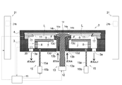
- FIG. 2 is an elevational sectional view of the vapor phase growth apparatus according to the embodiment of the present invention (part 1).
- FIG. 3 is an elevational sectional view of the vapor phase growth apparatus according to the embodiment of the present invention (No. 2). It is explanatory drawing explaining the member which comprises the vapor phase growth apparatus of FIG. 1 (the 1). It is explanatory drawing explaining the member which comprises the vapor phase growth apparatus of FIG. 1 (the 2). It is explanatory drawing explaining the operation
- FIG. 2 is an explanatory view for explaining the operation of the vapor phase growth apparatus of FIG. 1 (No. 2). It is explanatory drawing explaining the member which comprises the vapor phase growth apparatus of FIG. 1 (the 3).
- FIG. 20 is an explanatory diagram for explaining one step in another example of FIGS. 9 to 19 of the transfer method using the vapor phase growth apparatus of FIG. 1 (part 1);
- FIG. 20 is an explanatory view for explaining one step in another example of FIGS. 9 to 19 of the transfer method using the vapor phase growth apparatus of FIG. 1 (part 2);
- FIG. 20 is an explanatory diagram for explaining one step in another example of FIGS. 9 to 19 of the transfer method using the vapor phase growth apparatus of FIG. 1 (part 3);
- FIG. 20 is an explanatory view for explaining one step in another example of FIGS. 9 to 19 of the transfer method using the vapor phase growth apparatus of FIG. 1 (No. 4).
- FIG. 20 is an explanatory view for explaining one step in another example of FIGS. 9 to 19 of the transfer method using the vapor phase growth apparatus of FIG. 1 (No. 5).
- FIG. 20 is an explanatory view for explaining one step in another example of FIGS. 9 to 19 of the transfer method using the vapor phase growth apparatus of FIG. 1 (No. 6).
- FIG. 20 is an explanatory diagram for explaining one step in another example of FIGS. 9 to 19 of the transfer method using the vapor phase growth apparatus of FIG. 1 (part 7);
- FIG. 20 is an explanatory view for explaining one step in another example of FIGS. 9 to 19 of the transfer method using the vapor phase growth apparatus of FIG. 1 (No. 8).
- FIG. 20 is an explanatory view for explaining one step in another example of FIGS.
- FIG. 20 is an explanatory diagram for explaining one step in another example of FIGS. 9 to 19 of the transfer method using the vapor phase growth apparatus of FIG. 1 (No. 10).
- FIG. 20 is an explanatory diagram for explaining one step in another example of FIGS. 9 to 19 of the transfer method using the vapor phase growth apparatus of FIG. 1 (part 11); It is explanatory drawing of the other aspect of the susceptor of the vapor phase growth apparatus which concerns on this Embodiment.
- a vapor phase growth apparatus 1 is installed in a chamber 2 serving as a reaction furnace during vapor phase growth, and is rotatably and detachably installed on the chamber 2 side.
- a susceptor 7 having a disk shape for holding a substrate 5 (see FIG. 3) on which a semiconductor thin film is formed by vapor deposition, and a source gas for forming a semiconductor thin film covering the upper surface of the susceptor 7.
- a susceptor cover 9 that protects the susceptor 7, a ceiling plate 11 that is detachably installed so as to face the susceptor 7, and a nozzle that supports the ceiling plate 11 and supplies the source gas Portion 13, susceptor 7 on which susceptor cover 9 is placed, push-up / lowering mechanism 15 for raising / lowering susceptor cover 9, ceiling plate outer peripheral support portion 17 on which the outer peripheral portion of ceiling plate 11 is placed, susceptor 7, susceptor
- the transport arm 19 for carrying in and out the cover 9 and the ceiling plate 11, the susceptor 7, the temporary placing device 21 for temporarily holding the susceptor cover 9 and the ceiling plate 11, the nozzle part 13, the lifting and lowering mechanism 15, the outer periphery of the ceiling plate
- a support unit 17, a transport arm 19, and a control unit 16 that controls the operation of the temporary placement device 21 are included.
- the chamber 2 has a cylindrical shape with a flat shape and closed at both ends.
- the chamber 2 can be divided vertically into a chamber main body 3 having a bottomed cylindrical shape and a chamber lid 4 having a bottomed cylindrical shape covering the opening side of the chamber main body 3.
- the chamber body 3 is fixedly provided with the opening side up.
- the chamber lid 4 is provided to be movable up and down above the chamber body 3 with the opening side down.
- the chamber body 3 and the chamber lid 4 have a cylindrical shape that is hermetically sealed by lowering the chamber lid 4 and aligning the openings, so that a semiconductor thin film can be formed on the substrate 5. It becomes a reactor.
- the chamber lid 4 As the material of the chamber body 3 and the chamber lid 4, stainless steel having excellent corrosion resistance can be used.
- the chamber lid 4 has been described as an example that moves only in the vertical direction. However, the chamber lid 4 may move in the vertical direction and move in the horizontal direction to a predetermined position.
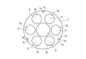
- the susceptor 7 has an annular plate shape having an opening 7 a through which the upper portion of the nozzle portion 13 can be inserted, and a susceptor rotating mechanism 8 provided in the chamber body 3. It is detachably and rotatably installed (see FIGS. 1 and 2).
- a plurality of substrate mounting portions 7b on which the substrate 5 on which the thin film is formed are mounted are provided at equal intervals in the circumferential direction.
- FIG. 3 shows a state in which the substrate 5 is placed on the substrate placing portion 7b.
- Three through holes 7 c are provided on the outer periphery of the susceptor 7.
- the through-hole 7c allows a push-up bar 15a (details will be described later) of the push-up / lowering mechanism 15 to pass therethrough.
- a push-up bar 15a (details will be described later) of the push-up / lowering mechanism 15 to pass therethrough.
- carbon can be used as the material of the susceptor 7.
- the material of the substrate 5 is selected according to the material of the semiconductor thin film to be formed.
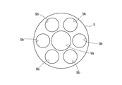
- the susceptor cover 9 has an annular plate shape that is substantially the same shape as the susceptor 7 in plan view, and an opening 9a into which the upper part of the nozzle portion 13 can be inserted at the center, And a plurality of openings 9b.
- the susceptor cover 9 is placed on the susceptor 7 and protects the susceptor 7 from contamination, oxidation, and the like by the source gas.
- the upper surface of the susceptor cover 9 and the upper surface of the substrate 5 placed on the substrate placing portion 7b of the susceptor 7 are flush with each other.
- a source gas flow path L is formed by these surfaces and the lower surface of the ceiling plate 11.
- quartz is used as the material of the susceptor cover 9.
- the ceiling plate 11 is formed of a disk having an opening 11 a (see FIG. 1) into which a convex portion 14 of a nozzle device 13 described later can be inserted.
- 2 and 6 illustrate a state in which the convex portion 14 of the nozzle device 13 is inserted into the opening 11 a of the ceiling plate 11 and the ceiling plate 11 is placed and supported at the center of the nozzle device 13. It is.
- the ceiling plate 11 is placed on the nozzle device 13 as described above, the lower surface of the ceiling plate 11 and the upper surface of the susceptor cover 9 form a source gas flow path L for forming a semiconductor thin film ( (See FIG. 2).
- the ceiling plate 11 is in contact with the nozzle device 13 with its own weight without any gap, and the source gas is prevented from leaking from the flow path L.
- quartz can be used as the material of the ceiling plate 11.
- the nozzle device 13 is installed in the center of the chamber body 3 and supplies the source gas to the source gas flow path L.
- the nozzle device 13 includes a push-up nozzle 13 a that is movable in the vertical direction, and a plurality of nozzles 13 that are spaced apart from the push-up nozzle 13 a by a predetermined distance in the radial direction to form a gas introduction path F for a source gas. It has wall members (fixed nozzle wall member 13b, fixed nozzle wall member 13c, fixed nozzle wall member 13d).
- the push-up nozzle 13a has a convex portion 14 formed at its upper end, and the convex portion 14 has a tapered surface 14a that gradually decreases in diameter and a placement portion 14b on which the central portion of the ceiling plate 11 is placed. Is formed.
- the convex portion 14 is inserted into the opening portion 11a so that the horizontal position of the ceiling plate 11 does not shift.
- the tapered surface 14 a has a function of guiding the ceiling plate 11 to facilitate the horizontal positioning of the ceiling plate 11 when the convex portion 14 is inserted into the opening 11 a of the ceiling plate 11.
- the vertical movement of the push-up nozzle 13a is performed by a vertical movement device 12 having a pulse motor or the like.
- the vertical movement device 12 can adjust the vertical position of the push-up nozzle 13a with high accuracy (sub-milli-order) by a pulse motor or the like.
- the up-and-down position of the ceiling plate 11 can be adjusted by the push-up nozzle 13a moving up and down while the ceiling plate 11 is supported by the mounting portion 14b, thereby adjusting the height of the flow path L with high accuracy. It is possible.
- the fixed nozzle wall member 13b is formed in a tubular shape having a diameter larger than the diameter of the cylinder of the push-up nozzle 13a, and has one end projecting outward.
- the fixed nozzle wall member 13c is formed in a tubular shape having a diameter larger than that of the fixed nozzle wall member 13b, and has one end projecting outward like the fixed nozzle wall member 13b.
- the fixed nozzle wall member 13d is formed in a tubular shape having a diameter larger than that of the fixed nozzle wall member 13c, and has one end projecting outward like the fixed nozzle wall member 13b.
- the thrust nozzle 13a, the fixed nozzle wall member 13b, the fixed nozzle wall member 13c, and the fixed nozzle wall member 13d are arranged in a nested manner, so that a space is formed between adjacent members of each member, and each space is a flow path.
- a gas introduction path F for introducing a source gas into L is provided.
- Source gas is supplied to each gas introduction path F from a source gas supply unit (not shown).
- a source gas supply unit not shown.
- the semiconductor thin film to be formed is gallium nitride
- an organic metal gas, an ammonia gas, and a purge gas are supplied from the source gas supply unit (see arrows in FIG. 2).
- the source gas supplied from the nozzle device 13 flows in the source gas flow path L formed by the upper surface of the susceptor cover 9 and the lower surface of the ceiling plate 11 from the center of the chamber body 3 toward the outer periphery, It discharges
- a semiconductor thin film is formed on the surface of the substrate 5 placed on the susceptor 7.
- the material of the source gas is selected according to the type of semiconductor thin film to be formed.
- the nozzle device 13 is not limited to the configuration shown in FIG. 1 and may be configured to support the ceiling plate 11 and move up and down and to supply the source gas to the source gas flow path L. Anything is acceptable.
- the push-up / lowering mechanism 15 has three push-up bars 15a installed so as to be arranged at the same positions as the through holes 7c (see FIG. 3) of the susceptor 7 installed in the chamber body 3, and raises / lowers the push-up bars 15a. Elevating means 15b (see FIGS. 1 and 2).
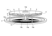
- FIG. 5 shows a state where the susceptor 7 and the like are removed so that the bottom of the chamber body 3 can be seen.
- the push-up / lowering mechanism 15 pushes up and supports the susceptor 7 from below, so that the susceptor 7 can be lifted / lowered together with the susceptor cover 9 placed on the susceptor 7 as shown in FIG.
- the rotation angle of the susceptor 7 is measured using the rotation angle sensor 20, and the susceptor 7 is rotated based on the measured rotation angle so that the through hole 7c is positioned directly above the upper end of the push rod 15a.
- the push-up rod 15a By aligning and raising the push-up rod 15a, the push-up rod 15a can pass through the through hole 7c, push up only the susceptor cover 9, and can be lifted and lowered in a supported state.
- the relative position of the through-hole 7c and the push-up rod 15a is adjusted to appropriately select whether the susceptor 7 is pushed up together with the susceptor cover 9 or only the susceptor cover 9 is pushed up. be able to.
- the susceptor 7 can be stably supported as described above.
- the number of the through-holes 7c of the susceptor 7 is three in the above description, it may be appropriately increased or decreased according to the number of the push-up bars 15a.
- the ceiling plate outer peripheral support portion 17 is on the outer peripheral side of the ceiling plate 11 and is detachable from either the chamber body 3 or the chamber lid 4.
- the ceiling plate outer periphery support portion 17 moves up and down in conjunction with the elevation of the chamber lid 4 when the chamber 2 is opened and closed.
- the outer peripheral part of the ceiling board 11 is supported by the ceiling board outer peripheral support part 17, and the ceiling board 11 also moves up and down.
- the ceiling plate outer periphery support portion 17 when the ceiling plate outer periphery support portion 17 is attached to the chamber body 3, only the chamber lid 4 can be raised while the ceiling plate 11 is placed on the ceiling plate outer periphery support portion 17 when the chamber 2 is opened and closed. it can.
- the ceiling plate outer periphery support portion 17 is attached to the chamber body 3 when the ceiling plate 11 is not lifted or lowered as the chamber 2 is opened or closed, and is attached to the chamber lid 4 when the ceiling plate 11 is desired to be lifted or lowered.
- the transfer arm 19 is installed outside the chamber 2, and transfers one or more or all of the susceptor 7, the susceptor cover 9, and the ceiling plate 11 to the inside and outside of the chamber 2.
- the transfer arm 19 has a plate having a substantially U shape in plan view, and has two upper and lower stages (an upper stage part 19a and a lower stage part 19b) as shown in FIG.
- the upper step portion 19a and the lower step portion 19b are connected by a connecting portion 19c (see FIG. 1) at a U-shaped curved portion.
- the upper step portion 19a and the lower step portion 19b are substantially the same size in plan view as shown in FIG. 7, and these are smaller than the susceptor 7 and the susceptor cover 9, and the susceptor 7 and the susceptor cover 9 are arranged in the upper step portion 19a and When placed on the lower step portion 19b, the outer periphery of the susceptor 7 and the susceptor cover 9 is set so as to protrude.
- the upper step portion 19a and the lower step portion 19b have a size and a shape that allows the upper portion 19a and the lower step portion 19b to enter above the chamber body 3 through the gap between the three push-up rods 15a. Is set.
- the push-up nozzle 13a enters the inside of the U-shaped curved portion of the transfer arm 19 so that they do not interfere with each other. It has become.
- the distance between the upper step portion 19a and the lower step portion 19b, that is, the height of the connecting portion 19c is determined by the operation range of the push-up nozzle 13a of the nozzle portion 13, the operation range of the push-up rod 15a of the push-up / lowering mechanism 15, and the temporary placement device described below.
- the transfer target member is transferred between the upper step portion 19 a and the lower step portion 19 b of the transfer arm 19 and the upper step support portion 23 and the lower step support portion 25 of the temporary placement device 21. It is set to be performed smoothly.
- the temporary placement device 21 is for supporting and temporarily holding one or more or all of the susceptor 7, the susceptor cover 9, and the ceiling plate 11 above the chamber body 3.
- the temporary placement device 21 includes three support columns 21 a that are erected on the outer periphery of the chamber body 3 at equal intervals, and a rod shape that protrudes horizontally from the support column 21 a. It has a temporary arm 21b provided so as to be rotatable in the horizontal direction about the axis 21a (see the arrow in FIG. 5) and capable of moving up and down (see the arrow in FIG. 1). As shown in FIG.
- the tip of the temporary arm 21b has an upper support 23 at a position one step down from the upper surface of the temporary arm 21b, and a lower support 25 at a position further down from the upper support 23.
- the distance between the upper support portion 23 and the lower support portion 25 is set in consideration of the height of the upper step portion 19a and the lower step portion 19b of the transfer arm 19.
- the ceiling plate 11 is supported by the upper support portion 23 of the temporary placement arm 21b, and the susceptor cover 9 is provided by the lower support portion 25.
- the susceptor 7 on which the susceptor cover 9 is placed can be supported. Since the temporary placement device 21 is configured as described above, the temporary placement arm 21b is moved up and down while the transfer arm 19 on which the member such as the ceiling plate 11 is placed is positioned above the chamber body 3.
- the upper support portion 23 is set to the same height as the upper step portion 19 a of the transfer arm 19, and the lower support portion 25 is set to the same height as the lower step portion 19 b of the transfer arm 19, and each temporary placement arm 21 b is rotated to face the center of the chamber body 3. By moving it, the member placed on the transfer arm 19 can be received.
- the outer peripheral portion of the ceiling plate 11 placed on the upper stage portion 19a of the transport arm 19 is supported by the upper stage support portion 23 of the temporary placement arm 21b, and can be received.
- the outer periphery of the susceptor 7 and the susceptor cover 9 placed on the lower step portion 19b can be received by being supported by the lower support portion 25 of the temporary placement arm 21b.
- the position of the temporary placement arm 21b is referred to as a “receiving position”.
- the ceiling nozzle 11a is lifted and the ceiling plate 11 is supported by the thrust nozzle 13a, so that the ceiling plate 11 is delivered to the thrust nozzle 13a. It is possible. Further, in a state where the susceptor 7 or the susceptor cover 9 is supported by the lower support portion 25 of the temporary placement device 21, the susceptor 7 and the like are pushed up by raising the push-up rod 15a of the push-up / lowering mechanism 15 and supporting the susceptor 7 and the like. Delivery to the elevating mechanism 15 is possible.
- a centering piece 27 made of a small piece that can protrude from the vertical wall portion toward the tip of the temporary arm 21b is provided on each vertical wall portion of the upper support portion 23 and the lower support portion 25. ing. If members such as the ceiling plate 11 are placed on the upper support portion 23 and the lower support portion 25 and the centering pieces 27 of all temporary placement arms 21b are projected, each member will come from three sides. The center of each member can be aligned with the center of the chamber body 3 (centering).
- the centering piece 27 is operable by compressed air or the like.
- the temporary placement device 21 is shown as an example of a configuration in which three temporary placement arms 21b are provided at equal intervals on the outer periphery.
- the arrangement and number of the temporary placement arms 21b are not limited to the above configuration. There is no limitation as long as the member to be transported can be stably supported.
- the temporary arm 21b is illustrated in the case where the diameter of the ceiling plate 11 is larger than the diameters of the susceptor 7 and the susceptor cover 9, but the temporary arm 21b only needs to support a plurality of members at the same time. It is not limited to.
- the temporary placement device 21 can receive a member such as the ceiling plate 11 from the transfer arm 19. However, if the reverse procedure is used, the temporary placement device 21 delivers the member to the transfer arm 19. Is possible. Similarly, in the above description, it has been described that the temporary placement device 21 can deliver a member such as the ceiling plate 11 to the push-up nozzle 13a or the push-up lifting mechanism 15. However, if the reverse procedure is used, the temporary placement device 21 is pushed up. A member can be received from the nozzle 13a or the push-up / lowering mechanism 15.
- the control unit 16 controls operations of the nozzle unit 13, the push-up / lowering mechanism 15, the ceiling plate outer periphery support unit 17, the transfer arm 19, and the temporary placement device 21. Specifically, for example, operation control of the vertical movement device 12 that raises and lowers the push-up nozzle 13a, operation control of the raising / lowering means 15b that raises and lowers the push-up rod 15a of the push-up / lowering mechanism 15, and the chamber body 3 of the ceiling plate outer periphery support portion 17 Alternatively, control of mounting to the chamber lid 4, control of raising and lowering the chamber lid 4, control of the transport operation of the transport arm 19 to and from the chamber 2, movement of the temporary placement arm 21 b of the temporary placement device 21 and operation of the centering piece 27 are performed.
- Control are performed by executing a program provided in the control unit 16.
- the installation place of the control part 16 will not be specifically limited if operation
- a susceptor 7, a susceptor cover 9, and a ceiling plate 11 As a combination of members to be transported by the vapor phase growth apparatus 1, (1) a susceptor 7, a susceptor cover 9, and a ceiling plate 11, (2) a susceptor 7 and a susceptor cover 9, and (3) a susceptor cover 9 and a ceiling plate 11, There are five types, (4) only the susceptor cover 9 and (5) only the ceiling plate 11. As an example, a description will be given of (1) the transfer method in which the susceptor 7, the susceptor cover 9, and the ceiling plate 11 are transferred, and the used susceptor 7, the susceptor cover 9, and the ceiling plate 11 used in the vapor phase growth process. A method of exchanging for the one before use will be described with reference to FIGS.
- the operation of the components of the vapor phase growth apparatus 1 in each process is controlled by the control unit 16.
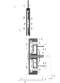
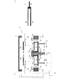
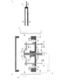
- FIG. 9 shows a state after the vapor phase growth process, in which the chamber lid 4 is in contact with the chamber body 3 and the chamber 2 is closed.
- the used susceptor 7 (A) is supported by the susceptor rotating mechanism 8 in a state where the substrate 5 is placed on the plate placing portion 7b.
- a susceptor cover 9 (A) is placed on the susceptor 7 (A).
- the ceiling plate 11 (A) is supported by the placement portion 14b of the push-up nozzle 13a.
- the upper end surface of the push-up bar 15a is located below the susceptor 7 (A).
- the ceiling board outer periphery support part 17 is attached to the chamber lid 4.
- the transfer arm 19 and the temporary placement arm 21 b are retracted out of the chamber 2.
- the ceiling plate 11 (B) before use is placed on the upper stage portion 19a of the transfer arm 19, and the susceptor 7 (B) before use is placed with the susceptor cover 9 (B) on the lower stage portion 19b. It is placed in. With the above state as the initial position, the first to sixth steps described below are sequentially performed.
- the ceiling board outer periphery support part 17 is attached to the chamber body 3 side, and the chamber 2 is opened by raising the chamber lid 4 from the initial position to a position higher than the upper stage part 19a of the transfer arm 19 (see FIG. 10). ). At this time, since the ceiling board outer periphery support part 17 is attached to the chamber body 3, the ceiling board outer periphery support part 17 remains in the initial position while supporting the outer periphery of the ceiling board 11 (A).
- the transfer arm 19 is moved in the horizontal direction and positioned above the chamber body 3 (see FIG. 11).
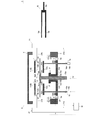
- the temporary placement arm 21b is moved from the initial position to the receiving position, and the outer peripheral portion of the ceiling plate 11 (B) protruding from the upper step portion 19a is supported by the upper support portion 23 of the temporary placement device 21.
- the ceiling board 11 (B) is received by the temporary placement device 21.
- the susceptor 7 (B) on which the susceptor cover 9 (B) is placed is temporarily placed by supporting the outer peripheral portion of the susceptor 7 (B) protruding from the lower step portion 19 b with the lower support portion 25. It is received by the device 21.
- the transfer arm is retracted out of the chamber after delivery of each member (see FIG. 12). Thereafter, the temporary placement arm 21b of the temporary placement device 21 is raised, and the ceiling plate 11 (B), the susceptor 7 (B), and the susceptor cover 9 (B) before use are retracted upward (see FIG. 13).
- the ceiling plate 11 (B), the susceptor 7 (B), and the susceptor cover 9 (B) can be temporarily placed above the chamber body 3, and therefore a place for temporary placement needs to be provided separately. Therefore, the vapor phase growth apparatus can be miniaturized. After each member is received by the temporary placement device 21, the centering pieces 27 of the upper support portion 23 and the lower support portion 25 are operated to center the ceiling plate 11 (B) and the susceptor 7 (B).
- the transfer arm 19 is moved in the horizontal direction so that the upper stage portion 19a of the transfer arm 19 is pushed up and positioned between the used ceiling board 11 (B) and the susceptor cover 9 (B).
- the lower step portion 19b of the transfer arm 19 is positioned below the susceptor 7 (B) after use that has been pushed up.
- the used ceiling plate 11 (B) is placed on the upper stage portion 19a of the transfer arm 19, and the used susceptor 7 (B) and the susceptor cover 9 are used.
- (B) can be placed on the lower part 19 b of the transfer arm 19. In this way, the used ceiling plate 11 (B) and the like are delivered to the transfer arm 19.
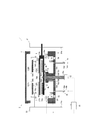
- the push-up nozzle 13a and push-up bar 15a are lowered as they are to return to the initial position (see FIG. 15). Thereafter, the transfer arm 19 is moved out of the chamber 2. Thereby, the used ceiling board 11 (A) and the like are carried out of the chamber 2 (see FIG. 16). After unloading, the vapor-phase grown substrate 5 placed on the susceptor 7 (A) can be collected, and the unloaded ceiling plate 11 (A) and the like can be washed.
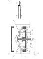
- the push-up rod 15a is lowered, and the susceptor 7 (B) is rotatably mounted on the susceptor rotating mechanism 8. Further, the push-up nozzle 13a is moved downward to place the outer peripheral portion of the ceiling plate 11 (B) in the concave portion of the ceiling plate outer peripheral support portion 17 (see FIG. 19). By doing so, a raw material gas flow path L is formed between the lower surface of the ceiling plate 11 and the upper surface of the susceptor cover 9 (B). At this time, since the ceiling plate 11 and the push-up nozzle 13a are in contact with each other with no gap, the vapor phase growth can be performed without the source gas leaking from the flow path L.
- the push-up nozzle 13a and the push-up bar 15a are lowered so that the ceiling plate 11 (B) and the like before use are in the same position as the initial position.
- the susceptor 7 (B) susceptor cover 9 ( Since B)
- the height of the flow path L can be set to a predetermined height by adjusting the position of the ceiling plate 11. Therefore, by making the height of the flow path L the same every time, the flow of the source gas can be made constant, and hence the reproducibility of the vapor phase growth can be increased (see FIG. 19).
- the initial state is that the susceptor 7, the susceptor cover 9 and the ceiling plate 11 are to be transported except that only the susceptor cover 9 (B) before use is placed on the lower step portion 19 b of the transport arm 19. (Same as (1) above) (see FIG. 20).
- the above state as the initial position, the following first to sixth steps are sequentially performed.
- the transfer arm 19 is moved in the horizontal direction and positioned above the chamber body 3 (see FIG. 22).
- the temporary placing arm 21 b of the temporary placing device 21 is moved from the initial position to the receiving position, and the susceptor cover 9 (B) placed on the lower step portion 19 b of the transfer arm 19 is received by the lower step support portion 25.
- the transfer arm 19 is retracted out of the chamber 2 after delivery of the susceptor cover 9 (B) (see FIG. 23).
- the temporary arm 21b is raised and the susceptor cover 9 (B) before use is retracted upward (see FIG. 24).
- the centering piece 27 of the lower stage support portion 25 is operated, and the core of the susceptor cover 9 (B) is operated. Make a delivery.
- the transfer arm 19 is moved in the horizontal direction to be positioned below the used susceptor cover 9 (A). Then, the used susceptor cover 9 (A) is placed on the lower step portion 19 b of the transport arm 19 by lowering the push-up bar 15 a. In this way, the used susceptor cover 9 (A) is transferred to the transfer arm 19. The push-up bar 15a is lowered as it is to return to the initial position (see FIG. 26). Thereafter, the transfer arm 19 is moved out of the chamber 2. Thereby, the used susceptor cover 9 (A) is carried out of the chamber 2 (see FIG. 27).
- the temporary placement arm 21b of the temporary placement device is lowered to lower the susceptor cover 9 (B) before use, which has been retracted upward, and the push-up rod 15a is lifted, and the push-up rod 15a raises the susceptor.
- the cover 9 (B) is supported (see FIG. 28).
- the temporary placement arm 21b of the temporary placement device 21 is rotated and retracted out of the chamber 2 (see FIG. 29).
- the push-up bar 15a is lowered so that the susceptor cover 9 (B) before use is in the same position as the initial position. In this way, the susceptor cover 9 (B) is placed on the susceptor 7 (see FIG. 30). Thus, the replacement of the susceptor cover 9 is completed. Thereafter, if the chamber lid 4 is lowered and the chamber 2 is closed, the vapor phase growth process can be performed again.
- the chamber 2 that serves as a reaction furnace during vapor phase growth
- the susceptor 7 that has a disk shape and is detachably installed on the chamber 2 side to hold the substrate
- the susceptor 7 A susceptor cover 9 that covers the upper surface of the susceptor 7 and protects the susceptor 7 from the source gas
- a ceiling plate 11 that is detachably installed so as to face the susceptor cover 9 and forms a flow path of the susceptor cover 9 and the source gas
- Productivity is provided by including a temporary placement device 21 that can temporarily hold one or more or all of the susceptor 7, the susceptor cover 9, and the ceiling plate 11 in the same position as the chamber 7 in a plan view.
- a compact vapor phase growth apparatus can be provided.
- the susceptor 7 or the susceptor cover 9 is provided with a push-up / lowering mechanism 15 that pushes up the susceptor 7 or the susceptor cover 9 from below and supports the susceptor 7 or the susceptor cover 9 so that it can be lifted / lowered. Therefore, it is not necessary to provide another mechanism separately, and the vapor phase growth apparatus can be made compact.
- the susceptor 7 has a circular through hole 7c.
- the susceptor 7 may have any shape that allows the push-up rod 15a to pass therethrough.
- the through hole 7c and the through hole The shape may be such that a notch portion 7 d that extends from 7 c in the radially outward direction of the susceptor 7 and cuts out the outer peripheral portion of the susceptor 7 communicates. By doing so, it is possible to prevent the susceptor 7 from cracking or cracking in the susceptor 7 even when the temperature inside the susceptor 7 becomes high during the vapor phase growth process. It is possible to prevent the life of the susceptor 7 from being reduced.
- the up-and-down position of the ceiling board 11 can be adjusted in the state which supported the ceiling board 11 by the thrust nozzle 13a of the nozzle apparatus 13, the height of the flow path L is set to the same every time. Therefore, the reproducibility of the vapor phase growth process can be increased.
Landscapes
- Chemical & Material Sciences (AREA)
- General Chemical & Material Sciences (AREA)
- Chemical Kinetics & Catalysis (AREA)
- Engineering & Computer Science (AREA)
- Materials Engineering (AREA)
- Mechanical Engineering (AREA)
- Metallurgy (AREA)
- Organic Chemistry (AREA)
- Container, Conveyance, Adherence, Positioning, Of Wafer (AREA)
Abstract
Description
また、天井板等の交換はグローボックス内に設置したロボットアームによって行われるが、交換スペースがチャンバーと別の場所に設けられていることから、交換に要するサイクルタイムが長くなり、生産性が低下するという問題もある。
円板状からなり前記チャンバー本体側に着脱可能に設置されて前記基板を保持するサセプタと、
該サセプタにおける基板保持部以外の部位を覆うように該サセプタ上に載置されるサセプタカバーと、
前記サセプタとの間に所定の間隔を離して対向配置されて前記原料ガスの流路を形成する天井板と、
前記チャンバーが分割された際に形成される前記チャンバー本体の上方空間に、前記サセプタ、前記サセプタカバー、前記天井板のうち少なくとも1つを一時的に仮置きする仮置き装置とを有することを特徴とするものである。
前記天井板を昇降可能に支持するとともに前記原料ガスを供給するノズル部と、
前記サセプタカバーが載置されたサセプタまたは前記サセプタカバーを下方から突き上げて昇降可能に支持する突き上げ昇降機構と、
前記搬送アーム、前記ノズル部、前記突き上げ昇降機構および、前記仮置き装置の動作を制御する制御部を備えたことを特徴とするものである。
前記突き上げ昇降機構は、
前記チャンバー本体の外周部に昇降可能に立設された複数の突き上げ棒と、該各突き上げ棒の上端面を常時は、前記チャンバー側に設置された状態の前記サセプタよりも下方に位置させ、動作時には前記チャンバー側に設置された状態の前記サセプタに載置された前記サセプタカバーよりも上方に上昇させる昇降手段と、前記サセプタを回転させて前記各貫通孔の位置と前記突き上げ棒の上端面との相対位置を制御することによって、前記サセプタを突き上げるか、前記サセプタカバーを突き上げるかを選択する機能とを有することを特徴とするものである。
前記サセプタ、前記サセプタカバー、前記天井板のうち少なくとも1つを前記搬送アームで搬送して前記仮置き装置に渡して保持させる工程と、
前記ノズル部で前記天井板を上昇させる工程と、
前記突き上げ昇降機構で前記サセプタ及び/又は前記サセプタカバーを上昇させる工程と、
前記ノズル部および/または前記突き上げ昇降機構で保持した部材を前記搬送アームに渡して搬送する工程と
前記天井板を保持した状態の前記仮置き装置から前記ノズル部に前記天井板を受渡す工程と、
前記サセプタと前記サセプタカバーを保持した状態の前記仮置き装置から前記突き上げ昇降機構に前記サセプタ及び/又は前記サセプタカバーを受渡す工程とを実現するプログラムを備えてなることを特徴とするものである。
前記上段部で保持する部材と前記下段部で保持する部材とが互いに接触しないように保持可能なことを特徴とするものである。
以下、各構成を詳細に説明する。
チャンバー2は、図2に示すように、概形が偏平して両端が閉じた円筒状からなる。チャンバー2は、有底円筒状からなるチャンバー本体3と、チャンバー本体3の開口側を覆う有底円筒状からなるチャンバー蓋4とに上下に分割可能になっている。
チャンバー本体3は、開口側を上にして固定して設けられている。チャンバー蓋4は、開口側を下にしてチャンバー本体3の上方に昇降可能に設けられている。
チャンバー本体3とチャンバー蓋4は、図2に示すように、チャンバー蓋4を下降させて開口部同士を合わせることで密閉された円筒状になり、基板5上に半導体薄膜を成膜するための反応炉となる。
チャンバー本体3およびチャンバー蓋4の材質には、耐食性に優れたステンレスを用いることができる。
なお、上記では、チャンバー蓋4は上下方向のみに移動するものを例として説明したが、所定の位置まで上下方向に移動するとともに水平方向に移動してもよい。
サセプタ7は、図3の平面図に示すように、中央にノズル部13の上部が挿通可能な開口部7aを有する円環板状からなり、チャンバー本体3内に設けられたサセプタ回転機構8に着脱可能にかつ回転可能に設置されている(図1および図2参照)。
開口部7aの周りには、薄膜が形成される基板5が載置される基板載置部7bが周方向に等間隔に複数設けられている。なお、図3は基板載置部7bに基板5を載置した状態を示している。
サセプタ7の外周部には、3つの貫通孔7cが設けられている。貫通孔7cは突き上げ昇降機構15の突き上げ棒15a(詳細は後述する)が貫通可能になっている。
なお、サセプタ7の材質には、例えばカーボンを用いることができる。また、基板5の材質は、成膜する半導体薄膜の材料に合わせて選択される。
サセプタカバー9は、図4の平面図に示すように、平面視でサセプタ7とほぼ同形の円環板状からなり、中央にノズル部13の上部が挿入可能な開口部9aと、開口部9aの周りに複数の開口部9bとを有している。
サセプタカバー9は、サセプタ7上に載置されて原料ガスによる汚染や酸化等からサセプタ7を保護するものである。サセプタカバー9がサセプタ7上に載置されると、サセプタカバー9の上面とサセプタ7の基板載置部7bに載置された基板5との上面とが面一になるようになっており、これらの面と天井板11の下面とで原料ガスの流路Lが形成されている。なお、サセプタカバー9の材質には、例えば石英が用いられる。
天井板11は、図2、図6に示すように、中央には後述するノズル装置13の凸部14が挿入可能な開口部11a(図1参照)を有する円板からなる。
図2、図6は、天井板11の開口部11aにノズル装置13の凸部14が挿入されて、天井板11がノズル装置13の中央に載置されて支持されている状態を図示したものである。
上記のように天井板11がノズル装置13に載置されると、天井板11の下面とサセプタカバー9の上面とで、半導体薄膜を成膜するための原料ガスの流路Lを形成する(図2参照)。このとき、天井板11は自重でノズル装置13と隙間なく当接しており、原料ガスが流路Lから漏れ出ることを防止している。
なお、天井板11の材質には、例えば石英を用いることができる。
ノズル装置13は、チャンバー本体3の中央に設置されて、原料ガスの流路Lに原料ガスを供給する。
ノズル装置13は、図1に示すように、上下方向に可動する突き上げノズル13aと、この突き上げノズル13aと径方向に所定間隔を離して複数配置されて原料ガスのガス導入路Fを形成するノズル壁部材(固定ノズル壁部材13b、固定ノズル壁部材13c、固定ノズル壁部材13d)を有している。
天井板11が載置部14bに載置されると、開口部11aに凸部14が挿入されることで天井板11の水平方向の位置がずれないようになっている。
また、テーパ面14aは天井板11の開口部11aに凸部14が挿入される際に、天井板11をガイドして天井板11の水平方向の位置決めを容易にする機能を有している。
突き上げノズル13aが、載置部14bで天井板11を支持した状態で上下動することで、天井板11の上下位置を調整することができ、これによって流路Lの高さを高精度に調整可能になっている。
また、固定ノズル壁部材13cは、固定ノズル壁部材13bよりも大径の管状からなり、一端が固定ノズル壁部材13bと同様に外方に張り出した形状になっている。
また、固定ノズル壁部材13dは、固定ノズル壁部材13cよりもさらに大径の管状からなり、一端が固定ノズル壁部材13bと同様に外方に張り出した形状になっている。
なお、原料ガスの材料は、成膜する半導体薄膜の種類等に合わせて選択される。
突き上げ昇降機構15は、チャンバー本体3に設置されたサセプタ7の各貫通孔7c(図3参照)と同位置に配置可能に設置された3本の突き上げ棒15aと、これら突き上げ棒15aの昇降させる昇降手段15bとを有している(図1、図2参照)。なお、図5は、サセプタ7等を取り外して、チャンバー本体3の底部が見えるようにした状態を図示したものである。
突き上げ昇降機構15は、サセプタ7を下方から突き上げて支持することで、図6に示すように、サセプタ7に載置されているサセプタカバー9ごとサセプタ7を昇降可能になっている。
このように、突き上げ棒15aを上昇させる際に、貫通孔7cと突き上げ棒15aの相対位置を調整することで、サセプタカバー9ごとサセプタ7を突き上げるか、サセプタカバー9のみを突き上げるかを適宜選択することができる。
また、サセプタ7の貫通孔7cの数は、上記では3つとしたが、突き上げ棒15aの数に応じて適宜増減させてもよい。
天井板外周支持部17は、図1に示すように、天井板11の外周側にあって、チャンバー本体3またはチャンバー蓋4のいずれか一方に着脱可能になっている。天井板外周支持部17がチャンバー蓋4に装着されると、チャンバー2の開閉時に、チャンバー蓋4の昇降と連動して、天井板外周支持部17が昇降するようになっている。このとき天井板11の外周部が天井板外周支持部17によって支持されて、天井板11も昇降する。
他方、天井板外周支持部17がチャンバー本体3に装着されると、チャンバー2の開閉時に、天井板外周支持部17に天井板11が載置されたまま、チャンバー蓋4のみを上昇させることができる。
このように、天井板外周支持部17は、チャンバー2の開閉にともなって天井板11を昇降させない場合にはチャンバー本体3に装着され、昇降させたい場合にはチャンバー蓋4に装着される。
搬送アーム19は、チャンバー2の外に設置され、サセプタ7、サセプタカバー9、天井板11のいずれか1つ以上または全部をチャンバー2の内外に搬送する。
搬送アーム19は、図7に示すように平面視が略U字状の板を、図1に示すように上下2段(上段部19aおよび下段部19b)有している。上段部19aおよび下段部19bは、U字の曲線部において連結部19c(図1参照)によって連結されている。
また、上段部19aおよび下段部19bは、3本の突き上げ棒15aを上昇させた状態で、これら3本の突き上げ棒15aの隙間を通過してチャンバー本体3の上方に侵入可能な大きさや形状に設定されている。
また、突き上げノズル13aを上昇させた状態で搬送アーム19をチャンバー本体3の上方に侵入させたときに、搬送アーム19のU字の曲線部内側に突き上げノズル13aが入り込んで両者が干渉しないようになっている。
上段部19aと下段部19bの間隔、すなわち連結部19cの高さは、ノズル部13の突き上げノズル13aの稼動範囲、突き上げ昇降機構15の突き上げ棒15aの稼動範囲、および次に説明する仮置き装置21の仮置きアーム21bの形状を考慮して、搬送アーム19の上段部19aおよび下段部19bと、仮置き装置21の上段支持部23および下段支持部25との間で搬送対象部材の受け渡しが円滑に行われるように設定される。
仮置き装置21は、サセプタ7、サセプタカバー9、天井板11のいずれか1つ以上または全部を、チャンバー本体3の上方で支持して一時的に保持するためのものである。
仮置き装置21は、図1、図2および図5に示すように、チャンバー本体3の外周に等間隔に立設する3本の支柱21aと、支柱21aから水平方向に突き出す棒状からなり、支柱21aを軸に水平方向に回動可能(図5の矢印参照)かつ昇降可能(図1の矢印参照)に設けられた仮置きアーム21bを有している。
仮置きアーム21bの先端部は、図1に示すように、仮置きアーム21bの上面から一段下がった位置に上段支持部23と、上段支持部23からさらに一段下がった位置に下段支持部25を有している。上段支持部23と下段支持部25の間隔は、搬送アーム19の上段部19aおよび下段部19bの高さを勘案して設定される。
仮置き装置21は、以上のような構成であるから、天井板11等の部材を載置した搬送アーム19をチャンバー本体3の上方に位置させた状態で、仮置きアーム21bを昇降させて、上段支持部23を搬送アーム19の上段部19aと、下段支持部25を搬送アーム19の下段部19bとそれぞれ同じ高さにして、各仮置きアーム21bをチャンバー本体3の中心に向けるように回動させることで、搬送アーム19に載置された部材を受け取ることができる。
また、仮置き装置21の下段支持部25にサセプタ7またはサセプタカバー9を支持した状態で、突き上げ昇降機構15の突き上げ棒15aを上昇させてサセプタ7等を支持させることで、サセプタ7等を突き上げ昇降機構15に受渡し可能になっている。
なお、仮置き装置21は、上記では外周に等間隔に3つの仮置きアーム21bが設けられている構成を一例として示しているが、仮置きアーム21bの配置や数は、上記の構成に特に限定されず、搬送対象の部材を安定して支持できるようなものであればよい。
また、上記では、天井板11の直径がサセプタ7およびサセプタカバー9の直径より大きい場合の仮置きアーム21bを例示しているが、仮置きアーム21bは複数の部材を同時に支持できればよく、この形状に限定されない。
同様に、上記では、仮置き装置21は突き上げノズル13aや突き上げ昇降機構15へ天井板11等の部材を受渡し可能であることを説明したが、逆の手順にすれば、仮置き装置21は突き上げノズル13aや突き上げ昇降機構15から部材を受取り可能である。
制御部16は、ノズル部13、突き上げ昇降機構15、天井板外周支持部17、搬送アーム19、仮置き装置21の動作を制御する。具体的には、例えば、突き上げノズル13aの昇降を行う上下動装置12の動作制御、突き上げ昇降機構15の突き上げ棒15aを昇降させる昇降手段15bの動作制御、天井板外周支持部17のチャンバー本体3またはチャンバー蓋4への装着の制御、チャンバー蓋4の昇降制御、搬送アーム19のチャンバー2内外への搬送動作の制御、仮置き装置21の仮置きアーム21bの移動および芯出し片27の動作を制御する。これらの制御は、制御部16に設けられたプログラムを実行することで行われる。なお、制御部16の設置場所は、ノズル部13、突き上げ昇降機構15、天井板外周支持部17、搬送アーム19、仮置き装置21の動作の制御が可能であれば、特に限定されない。
例として、上記の(1)サセプタ7とサセプタカバー9と天井板11を搬送対象にした搬送方法について説明するとともに、気相成長処理で使用した使用後のサセプタ7、サセプタカバー9および天井板11を、使用前のものに交換する方法について、以下に図9~図19に基づいて説明する。
なお、以下の説明や図中において、サセプタ7、サセプタカバー9および天井板11の使用前と使用後を区別するために、使用後のものには添え字(A)をつけてサセプタ7(A)、サセプタカバー9(A)および天井板11(A)とし、使用前のものには添え字(B)をつけてサセプタ7(B)、サセプタカバー9(B)および天井板11(B)とする。
各工程における気相成長装置1の構成要素の動作は、制御部16により制御する。
使用後のサセプタ7(A)は、板載置部7bに基板5が載置された状態でサセプタ回転機構8に支持されている。また、サセプタ7(A)にはサセプタカバー9(A)が載置されている。
天井板11(A)は、突き上げノズル13aの載置部14bに支持されている。突き上げ棒15aの上端面は、サセプタ7(A)よりも下方に位置している。天井板外周支持部17は、チャンバー蓋4に装着されている。
搬送アーム19および仮置きアーム21bはチャンバー2外に退避している。搬送アーム19の上段部19aには使用前の天井板11(B)が載置されており、下段部19bには使用前のサセプタ7(B)がサセプタカバー9(B)を載置した状態で載置されている。
上記の状態を初期位置として、以下に説明する第1~第6工程を順次行う。
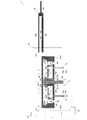
まず、天井板外周支持部17をチャンバー本体3側に装着して、チャンバー蓋4を初期位置から搬送アーム19の上段部19aよりも高い位置まで上昇させることでチャンバー2を開放する(図10参照)。このとき、天井板外周支持部17はチャンバー本体3に装着されているため、天井板外周支持部17は天井板11(A)の外周部を支持した状態で初期位置に留まっている。
次に、搬送アーム19を水平方向に移動させて、チャンバー本体3の上方に位置させる(図11参照)。
次に、仮置きアーム21bを初期位置から受取位置に移動させて、上段部19aからはみ出している天井板11(B)の外周部を仮置き装置21の上段支持部23で支持することで、天井板11(B)を仮置き装置21で受取る。また、これともに、下段部19bからはみ出しているサセプタ7(B)の外周部を下段支持部25で支持することで、サセプタカバー9(B)が載置されたサセプタ7(B)を仮置き装置21で受取る。搬送アームは各部材の受渡し後、チャンバー外に退避させる(図12参照)。
その後、仮置き装置21の仮置きアーム21bを上昇させて、使用前の天井板11(B)、サセプタ7(B)およびサセプタカバー9(B)を上方に退避させる(図13参照)。
各部材を仮置き装置21で受取った後、上段支持部23および下段支持部25の芯出し片27を作動させて、天井板11(B)およびサセプタ7(B)の芯出しを行う。
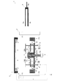
次に、突き上げノズル13aを初期位置から上昇させることで使用後の天井板11(A)を搬送アーム19の上段部19aの高さまで突き上げるとともに、突き上げ昇降機構15の突き上げ棒15aを初期位置から上昇させることで、使用後のサセプタ7(A)を搬送アーム19の下段部19bの高さまで突き上げる(図14参照)。
突き上げ棒15aを上昇させる際に、サセプタ7の貫通孔7cが、突き上げ棒15aの真上にある場合は、サセプタ回転機構8を用いてサセプタ7(A)を回転させて、突き上げ棒15aが貫通孔7cを貫通しないように貫通孔7cの位置をずらす。
このようにすることでサセプタカバー9ごとサセプタ7(A)を突き上げることができる。
次に、搬送アーム19を水平方向に移動させて、搬送アーム19の上段部19aを突き上げられた使用後の天井板11(B)とサセプタカバー9(B)との間に位置させ、これとともに、搬送アーム19の下段部19bを突き上げられた使用後のサセプタ7(B)の下方に位置させる。
その後、突き上げノズル13aおよび突き上げ棒15aを下降させることで、使用後の天井板11(B)を搬送アーム19の上段部19aに載置するとともに、使用後のサセプタ7(B)およびサセプタカバー9(B)を搬送アーム19の下段部19bに載置することができる。このようにして使用後の天井板11(B)等を搬送アーム19に受渡す。突き上げノズル13aおよび突き上げ棒15aはそのまま下降させて初期位置の状態に戻す(図15参照)。
その後、搬送アーム19をチャンバー2外に移動させる。これにより使用後の天井板11(A)等がチャンバー2外に搬出される(図16参照)。搬出後は、サセプタ7(A)に載置された気相成長後の基板5を回収し、また、搬出された天井板11(A)等は洗浄することができる。
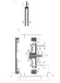
次に、仮置き装置の仮置きアーム21bを下降させることで、上方に退避させていた使用前の天井板11(B)等を下降させるとともに、突き上げノズル13aおよび突き上げ棒15aを上昇させて、突き上げノズル13aに天井板11(B)を、突き上げ棒15aにサセプタカバー9(B)が設置されたサセプタ7(B)を載置する(図17参照)。
このとき、天井板11(B)が予め芯出しされているため、天井板11(B)の突き上げノズル13aへの載置を正確に行うことができる。
その後、仮置き装置21の仮置きアーム21bを回動させてチャンバー2外に退避させる(図18参照)。
次に、突き上げ棒15aを下降させて、サセプタ7(B)をサセプタ回転機構8に回転可能に載置する。また、突き上げノズル13aを下動させて天井板11(B)の外周部を天井板外周支持部17の凹部に納める(図19参照)。こうすることによって、天井板11の下面とサセプタカバー9(B)の上面とで、原料ガスの流路Lが形成される。このとき、天井板11と突き上げノズル13aとが隙間なく当接しているので、流路Lから原料ガスが漏れ出ることなく気相成長を行うことができる。
このように、突き上げノズル13aおよび突き上げ棒15aを下降させて使用前の天井板11(B)等を初期位置と同位置になるようにするが、このときサセプタ7(B)(サセプタカバー9(B))が芯出しされて突き上げ棒15aに載置されているため、チャンバー本体3に正確に設置することができる。
上述したとおり、突き上げノズル13aは精密に位置調整が可能であるので、天井板11の位置を調整することにより、流路Lの高さを所定の高さに設定することができる。従って、流路Lの高さを毎回同じにすることで原料ガスの流れを一定にすることができ、それ故、気相成長の再現性を高くすることができる(図19参照)。
初期状態は、搬送アーム19の下段部19bには使用前のサセプタカバー9(B)のみが載置されている他は、上記のサセプタ7、サセプタカバー9および天井板11を搬送対象とした場合(上記の(1))と同様である(図20参照)。
上記の状態を初期位置として、以下に示す第1~第6工程を順次行う。
まず、天井板外周支持部17をチャンバー蓋4に装着したまま、チャンバー蓋4を搬送アーム19の上段部19aよりも高い位置まで上昇させてチャンバー2を開放する(図21参照)。このとき、天井板外周支持部17はチャンバー蓋4に装着されているため、チャンバー蓋4が上昇することによって天井板外周支持部17および天井板11は上昇する
次に、搬送アーム19を水平方向に移動させて、チャンバー本体3の上方に位置させる(図22参照)。
次に、仮置き装置21の仮置きアーム21bを初期位置から受取位置に移動させて、搬送アーム19の下段部19bに載置されているサセプタカバー9(B)を下段支持部25で受取る。搬送アーム19はサセプタカバー9(B)の受渡し後、チャンバー2外に退避させる(図23参照)。
その後、仮置きアーム21bを上昇させて、使用前のサセプタカバー9(B)を上方に退避させる(図24参照)。
サセプタカバー9(B)を仮置き装置21で受取った後、仮置き装置21で保持している間に、下段支持部25の芯出し片27を作動させて、サセプタカバー9(B)の芯出しを行う。
次に、突き上げ昇降機構15の突き上げ棒15aを上昇させて、サセプタ7の貫通孔7cを貫通させて、使用後のサセプタカバー9(A)のみを搬送アーム19の下段部19bの高さまで突き上げる(図25参照)。このとき、サセプタ7の貫通孔7cが、突き上げ棒15aによって貫通される位置にない場合は、サセプタ回転機構8を用いてサセプタ7を回転させて、突き上げ棒15aが貫通孔7cを貫通するように貫通孔7cの位置を予め合せておく。
次に、搬送アーム19を水平方向に移動させて、使用後のサセプタカバー9(A)の下方に位置させる。その後、突き上げ棒15aを下降させることで、使用後のサセプタカバー9(A)を搬送アーム19の下段部19bに載置する。このようにして使用後のサセプタカバー9(A)を搬送アーム19に受け渡す。突き上げ棒15aはそのまま下降させて初期位置の状態に戻す(図26参照)。
その後、搬送アーム19をチャンバー2外に移動させる。これにより使用後のサセプタカバー9(A)がチャンバー2外に搬出される(図27参照)。
次に、仮置き装置の仮置きアーム21bを下降させることで、上方に退避させていた使用前のサセプタカバー9(B)を下降させるとともに、突き上げ棒15aを上昇させて、突き上げ棒15aでサセプタカバー9(B)を支持する(図28参照)。
その後、仮置き装置21の仮置きアーム21bを回動させてチャンバー2外に退避させる(図29参照)。
次に、突き上げ棒15aを下降させて使用前のサセプタカバー9(B)を初期位置と同位置になるようにする。このようにして、サセプタカバー9(B)がサセプタ7に載置される(図30参照)。
以上でサセプタカバー9の交換が完了する。その後、チャンバー蓋4を下降させてチャンバー2を閉じれば、再び気相成長処理を行うことができる。
F ガス導入路
1 気相成長装置
2 チャンバー
3 チャンバー本体
3a 排出口
4 チャンバー蓋
5 基板
7 サセプタ
7a 開口部
7b 基板載置部
7c 貫通孔
8 サセプタ回転機構
9 サセプタカバー
9a 開口部
9b 開口部
11 天井板
12 上下動装置
13 ノズル部
13a 突き上げノズル
13b、13c、13d 固定ノズル壁
14 凸部
14a テーパ面
14b 載置部
15 突き上げ昇降機構
15a 突き上げ棒
15b 昇降手段
16 制御部
17 天井板外周支持部
19 搬送アーム
19a 上段部
19b 下段部
19c 連結部
21 仮置き装置
21a 支柱
21b 仮置きアーム
23 上段支持部
25 下段支持部
27 芯出し片
Claims (11)
- チャンバー本体とチャンバー蓋とに上下に分割可能なチャンバー内に設置された基板上に原料ガスを供給して前記基板上に薄膜を成長させる気相成長装置であって、
円板状からなり前記チャンバー本体側に着脱可能に設置されて前記基板を保持するサセプタと、
該サセプタにおける基板保持部以外の部位を覆うように該サセプタ上に載置されるサセプタカバーと、
前記サセプタとの間に所定の間隔を離して対向配置されて前記原料ガスの流路を形成する天井板と、
前記チャンバーが分割された際に形成される前記チャンバー本体の上方空間に、前記サセプタ、前記サセプタカバー、前記天井板のうち少なくとも1つを一時的に仮置きする仮置き装置とを有することを特徴とする気相成長装置。 - 前記仮置き装置は、前記チャンバー本体の上方空間に出入り可能な単数又は複数の仮置きアームを有し、該仮置きアームは、その先端に前記サセプタ、前記サセプタカバー、前記天井板のうち少なくとも1つを一時的に仮置きする仮置き部を備えてなることを特徴とする請求項1に記載の気相成長装置。
- 前記仮置き装置は、前記天井板を仮置きする天井板仮置き部と、前記サセプタカバーが載置されたサセプタまたは前記サセプタカバーを仮置きするサセプタ仮置き部とを有することを特徴とする請求項1又は2に記載の気相成長装置。
- 前記仮置き部は上段支持部と下段支持部の上下2段からなり、前記上段支持部が前記天井板仮置き部であり、前記下段支持部が前記サセプタ仮置き部であることを特徴とする請求項3に記載の気相成長装置。
- 前記仮置き装置は、仮置きした前記サセプタ、前記サセプタカバーまたは前記天井板の中心を前記チャンバー本体の中心に一致させる中心合せ機構を有していることを特徴とする請求項1乃至4のいずれか一項に記載の気相成長装置。
- 前記中心合せ機構は、仮置きした前記サセプタ、前記サセプタカバーまたは前記天井板の外周部における少なくとも3カ所に当接して前記サセプタ、前記サセプタカバーまたは前記天井板を中心方向へ微動させる芯出し片を備えてなることを特徴とする請求項5記載の気相成長装置。
- 前記芯出し片は、圧縮空気によって突出可能となっていることを特徴とする請求項6に記載の気相成長装置。
- 前記サセプタ、前記サセプタカバー、前記天井板のうち少なくとも1つを前記チャンバーの内外に搬送する搬送アームと、
前記天井板を昇降可能に支持するとともに前記原料ガスを供給するノズル部と、
前記サセプタカバーが載置されたサセプタまたは前記サセプタカバーを下方から突き上げて昇降可能に支持する突き上げ昇降機構と、
前記搬送アーム、前記ノズル部、前記突き上げ昇降機構および、前記仮置き装置の動作を制御する制御部を備えたことを特徴とする請求項1乃至7のいずれか1項に記載の気相成長装置。 - 前記サセプタの外周部には複数の貫通孔が設けられており、
前記突き上げ昇降機構は、
前記チャンバー本体の外周部に昇降可能に立設された複数の突き上げ棒と、該各突き上げ棒の上端面を常時は、前記チャンバー側に設置された状態の前記サセプタよりも下方に位置させ、動作時には前記チャンバー側に設置された状態の前記サセプタに載置された前記サセプタカバーよりも上方に上昇させる昇降手段と、前記サセプタを回転させて前記各貫通孔の位置と前記突き上げ棒の上端面との相対位置を制御することによって、前記サセプタを突き上げるか、前記サセプタカバーを突き上げるかを選択する機能とを有することを特徴とする請求項8に記載の気相成長装置。 - 前記制御部は、
前記サセプタ、前記サセプタカバー、前記天井板のうち少なくとも1つを前記搬送アームで搬送して前記仮置き装置に渡して保持させる工程と、
前記ノズル部で前記天井板を上昇させる工程と、
前記突き上げ昇降機構で前記サセプタ及び/又は前記サセプタカバーを上昇させる工程と、
前記ノズル部および/または前記突き上げ昇降機構で保持した部材を前記搬送アームに渡して搬送する工程と
前記天井板を保持した状態の前記仮置き装置から前記ノズル部に前記天井板を受け渡す工程と、
前記サセプタと前記サセプタカバーを保持した状態の前記仮置き装置から前記突き上げ昇降機構に前記サセプタ及び/又は前記サセプタカバーを受け渡す工程とを実現するプログラムを備えてなることを特徴とする請求項1乃至9に記載の気相成長装置。 - 前記搬送アームは、前記天井板を保持する上段部と、前記サセプタおよび前記サセプタカバー、または前記サセプタカバーを保持する下段部とを有しており、
前記上段部で保持する部材と前記下段部で保持する部材とが互いに接触しないように保持可能なことを特徴とする請求項8乃至10に記載の気相成長装置。
Priority Applications (2)
| Application Number | Priority Date | Filing Date | Title |
|---|---|---|---|
| US14/427,237 US20150232988A1 (en) | 2012-10-04 | 2013-09-26 | Vapor phase growth apparatus |
| KR1020147034229A KR20150060605A (ko) | 2012-10-04 | 2013-09-26 | 기상성장장치 |
Applications Claiming Priority (6)
| Application Number | Priority Date | Filing Date | Title |
|---|---|---|---|
| JP2012221858A JP6013121B2 (ja) | 2012-10-04 | 2012-10-04 | 気相成長装置 |
| JP2012-221860 | 2012-10-04 | ||
| JP2012221856A JP6059940B2 (ja) | 2012-10-04 | 2012-10-04 | 気相成長装置 |
| JP2012-221856 | 2012-10-04 | ||
| JP2012221860A JP6013122B2 (ja) | 2012-10-04 | 2012-10-04 | 気相成長装置 |
| JP2012-221858 | 2012-10-04 |
Publications (1)
| Publication Number | Publication Date |
|---|---|
| WO2014054501A1 true WO2014054501A1 (ja) | 2014-04-10 |
Family
ID=50434829
Family Applications (1)
| Application Number | Title | Priority Date | Filing Date |
|---|---|---|---|
| PCT/JP2013/076091 Ceased WO2014054501A1 (ja) | 2012-10-04 | 2013-09-26 | 気相成長装置 |
Country Status (4)
| Country | Link |
|---|---|
| US (1) | US20150232988A1 (ja) |
| KR (1) | KR20150060605A (ja) |
| TW (1) | TWI633202B (ja) |
| WO (1) | WO2014054501A1 (ja) |
Cited By (1)
| Publication number | Priority date | Publication date | Assignee | Title |
|---|---|---|---|---|
| JP2023527725A (ja) * | 2020-05-29 | 2023-06-30 | エルピーイー ソシエタ ペル アチオニ | オーバーヘッドスクリーンを有する基板を取り扱うためのツール、並びに関連する取り扱い方法及びエピタキシャル反応器 |
Families Citing this family (4)
| Publication number | Priority date | Publication date | Assignee | Title |
|---|---|---|---|---|
| JP6608332B2 (ja) * | 2016-05-23 | 2019-11-20 | 東京エレクトロン株式会社 | 成膜装置 |
| JP6777055B2 (ja) * | 2017-01-11 | 2020-10-28 | 東京エレクトロン株式会社 | 基板処理装置 |
| DE102024126450A1 (de) | 2024-09-13 | 2026-03-19 | Aixtron Se | CVD-Reaktor |
| WO2026057801A2 (de) | 2024-09-13 | 2026-03-19 | Aixtron Se | Cvd-reaktor |
Citations (3)
| Publication number | Priority date | Publication date | Assignee | Title |
|---|---|---|---|---|
| JPH02132950U (ja) * | 1989-04-10 | 1990-11-05 | ||
| JPH05160035A (ja) * | 1991-12-05 | 1993-06-25 | Kokusai Electric Co Ltd | Cvd装置 |
| JP2010232235A (ja) * | 2009-03-26 | 2010-10-14 | Taiyo Nippon Sanso Corp | 気相成長装置 |
Family Cites Families (11)
| Publication number | Priority date | Publication date | Assignee | Title |
|---|---|---|---|---|
| US3696779A (en) * | 1969-12-29 | 1972-10-10 | Kokusai Electric Co Ltd | Vapor growth device |
| JPH06310438A (ja) * | 1993-04-22 | 1994-11-04 | Mitsubishi Electric Corp | 化合物半導体気相成長用基板ホルダおよび化合物半導体気相成長装置 |
| JP4417669B2 (ja) * | 2003-07-28 | 2010-02-17 | 日本エー・エス・エム株式会社 | 半導体処理装置および半導体ウエハーの導入方法 |
| US7182816B2 (en) * | 2003-08-18 | 2007-02-27 | Tokyo Electron Limited | Particulate reduction using temperature-controlled chamber shield |
| US7128806B2 (en) * | 2003-10-21 | 2006-10-31 | Applied Materials, Inc. | Mask etch processing apparatus |
| US20050205209A1 (en) * | 2004-03-18 | 2005-09-22 | Aelan Mosden | Replacing chamber components in a vacuum environment |
| JP4607848B2 (ja) * | 2006-10-27 | 2011-01-05 | 東京エレクトロン株式会社 | 基板処理装置、基板受け渡し位置の調整方法及び記憶媒体 |
| JP2010125592A (ja) * | 2008-12-01 | 2010-06-10 | Hitachi Tool Engineering Ltd | 鋳鉄加工用ドリル |
| JP5317278B2 (ja) * | 2009-04-28 | 2013-10-16 | 大陽日酸株式会社 | 気相成長装置、気相成長装置における対向面部材またはサセプタ上面カバー取外し方法 |
| KR101569796B1 (ko) * | 2009-06-23 | 2015-11-20 | 주성엔지니어링(주) | 기판 정렬 장치, 이를 포함하는 기판 처리 장치 및 기판 정렬 방법 |
| CN102939648B (zh) * | 2010-06-01 | 2015-05-27 | 松下电器产业株式会社 | 等离子处理装置以及等离子处理方法 |
-
2013
- 2013-09-26 KR KR1020147034229A patent/KR20150060605A/ko not_active Withdrawn
- 2013-09-26 US US14/427,237 patent/US20150232988A1/en not_active Abandoned
- 2013-09-26 WO PCT/JP2013/076091 patent/WO2014054501A1/ja not_active Ceased
- 2013-09-30 TW TW102135291A patent/TWI633202B/zh active
Patent Citations (3)
| Publication number | Priority date | Publication date | Assignee | Title |
|---|---|---|---|---|
| JPH02132950U (ja) * | 1989-04-10 | 1990-11-05 | ||
| JPH05160035A (ja) * | 1991-12-05 | 1993-06-25 | Kokusai Electric Co Ltd | Cvd装置 |
| JP2010232235A (ja) * | 2009-03-26 | 2010-10-14 | Taiyo Nippon Sanso Corp | 気相成長装置 |
Cited By (2)
| Publication number | Priority date | Publication date | Assignee | Title |
|---|---|---|---|---|
| JP2023527725A (ja) * | 2020-05-29 | 2023-06-30 | エルピーイー ソシエタ ペル アチオニ | オーバーヘッドスクリーンを有する基板を取り扱うためのツール、並びに関連する取り扱い方法及びエピタキシャル反応器 |
| JP7741818B2 (ja) | 2020-05-29 | 2025-09-18 | エルピーイー ソシエタ ペル アチオニ | オーバーヘッドスクリーンを有する基板を取り扱うためのツール、並びに関連する取り扱い方法及びエピタキシャル反応器 |
Also Published As
| Publication number | Publication date |
|---|---|
| TWI633202B (zh) | 2018-08-21 |
| KR20150060605A (ko) | 2015-06-03 |
| US20150232988A1 (en) | 2015-08-20 |
| TW201420807A (zh) | 2014-06-01 |
Similar Documents
| Publication | Publication Date | Title |
|---|---|---|
| JP6068255B2 (ja) | 気相成長装置および気相成長装置の部材搬送方法 | |
| US20130291798A1 (en) | Thin film deposition apparatus and substrate treatment system including the same | |
| WO2014054501A1 (ja) | 気相成長装置 | |
| KR102125512B1 (ko) | 기판 처리 장치 및 기판 처리 방법 | |
| JP2016207932A (ja) | サセプタ及びエピタキシャル成長装置 | |
| TW201349377A (zh) | 獨立晶圓處理的方法及設備 | |
| JP6618876B2 (ja) | 基板処理装置、搬送方法およびサセプタ | |
| JP2010062446A (ja) | 縦型熱処理装置及び基板支持具 | |
| TWI505337B (zh) | 基板處理裝置 | |
| JP6059940B2 (ja) | 気相成長装置 | |
| JP2013098271A (ja) | 成膜方法および成膜装置 | |
| US20130108792A1 (en) | Loading and unloading system for thin film formation and method thereof | |
| JP6013122B2 (ja) | 気相成長装置 | |
| KR20170055141A (ko) | 기판 처리장치 및 기판 처리방법 | |
| JP6013121B2 (ja) | 気相成長装置 | |
| JP2016154196A (ja) | エピタキシャル成長装置及びサセプタサポートシャフト | |
| CN113488429A (zh) | 半导体设备及半导体工艺方法 | |
| JP2005223142A (ja) | 基板保持具、成膜処理装置及び処理装置 | |
| JP7257920B2 (ja) | 気相成長装置の基板搬送機構及び基板搬送方法 | |
| JP7257916B2 (ja) | 気相成長装置の基板搬送機構 | |
| JP2012178488A (ja) | サセプタカバー、該サセプタカバーを備えた気相成長装置 | |
| JP4668323B2 (ja) | シャワー型気相成長装置及びその気相成長方法 | |
| KR19990077900A (ko) | 박막제조장치 | |
| JP2009123860A (ja) | ウェーハ自動移載装置およびこれを用いたウェーハ移載方法 | |
| KR101559028B1 (ko) | 기판 지지 장치 및 이를 포함하는 기판 처리 장치 및 이들을 이용한 기판 처리 방법 |
Legal Events
| Date | Code | Title | Description |
|---|---|---|---|
| 121 | Ep: the epo has been informed by wipo that ep was designated in this application |
Ref document number: 13843409 Country of ref document: EP Kind code of ref document: A1 |
|
| ENP | Entry into the national phase |
Ref document number: 20147034229 Country of ref document: KR Kind code of ref document: A |
|
| WWE | Wipo information: entry into national phase |
Ref document number: 14427237 Country of ref document: US |
|
| NENP | Non-entry into the national phase |
Ref country code: DE |
|
| 122 | Ep: pct application non-entry in european phase |
Ref document number: 13843409 Country of ref document: EP Kind code of ref document: A1 |