WO2014054440A1 - 遠心圧縮機 - Google Patents
遠心圧縮機 Download PDFInfo
- Publication number
- WO2014054440A1 WO2014054440A1 PCT/JP2013/075497 JP2013075497W WO2014054440A1 WO 2014054440 A1 WO2014054440 A1 WO 2014054440A1 JP 2013075497 W JP2013075497 W JP 2013075497W WO 2014054440 A1 WO2014054440 A1 WO 2014054440A1
- Authority
- WO
- WIPO (PCT)
- Prior art keywords
- labyrinth seal
- labyrinth
- seal
- centrifugal compressor
- rotor
- Prior art date
- Legal status (The legal status is an assumption and is not a legal conclusion. Google has not performed a legal analysis and makes no representation as to the accuracy of the status listed.)
- Ceased
Links
Images



Classifications
-
- F—MECHANICAL ENGINEERING; LIGHTING; HEATING; WEAPONS; BLASTING
- F04—POSITIVE - DISPLACEMENT MACHINES FOR LIQUIDS; PUMPS FOR LIQUIDS OR ELASTIC FLUIDS
- F04D—NON-POSITIVE-DISPLACEMENT PUMPS
- F04D17/00—Radial-flow pumps, e.g. centrifugal pumps; Helico-centrifugal pumps
- F04D17/08—Centrifugal pumps
- F04D17/10—Centrifugal pumps for compressing or evacuating
- F04D17/12—Multi-stage pumps
-
- F—MECHANICAL ENGINEERING; LIGHTING; HEATING; WEAPONS; BLASTING
- F04—POSITIVE - DISPLACEMENT MACHINES FOR LIQUIDS; PUMPS FOR LIQUIDS OR ELASTIC FLUIDS
- F04D—NON-POSITIVE-DISPLACEMENT PUMPS
- F04D29/00—Details, component parts, or accessories
- F04D29/08—Sealings
- F04D29/10—Shaft sealings
- F04D29/102—Shaft sealings especially adapted for elastic fluid pumps
-
- F—MECHANICAL ENGINEERING; LIGHTING; HEATING; WEAPONS; BLASTING
- F04—POSITIVE - DISPLACEMENT MACHINES FOR LIQUIDS; PUMPS FOR LIQUIDS OR ELASTIC FLUIDS
- F04D—NON-POSITIVE-DISPLACEMENT PUMPS
- F04D17/00—Radial-flow pumps, e.g. centrifugal pumps; Helico-centrifugal pumps
- F04D17/08—Centrifugal pumps
- F04D17/10—Centrifugal pumps for compressing or evacuating
- F04D17/12—Multi-stage pumps
- F04D17/122—Multi-stage pumps the individual rotor discs being, one for each stage, on a common shaft and axially spaced, e.g. conventional centrifugal multi- stage compressors
-
- F—MECHANICAL ENGINEERING; LIGHTING; HEATING; WEAPONS; BLASTING
- F04—POSITIVE - DISPLACEMENT MACHINES FOR LIQUIDS; PUMPS FOR LIQUIDS OR ELASTIC FLUIDS
- F04D—NON-POSITIVE-DISPLACEMENT PUMPS
- F04D29/00—Details, component parts, or accessories
- F04D29/05—Shafts or bearings, or assemblies thereof, specially adapted for elastic fluid pumps
- F04D29/051—Axial thrust balancing
- F04D29/0516—Axial thrust balancing balancing pistons
-
- F—MECHANICAL ENGINEERING; LIGHTING; HEATING; WEAPONS; BLASTING
- F04—POSITIVE - DISPLACEMENT MACHINES FOR LIQUIDS; PUMPS FOR LIQUIDS OR ELASTIC FLUIDS
- F04D—NON-POSITIVE-DISPLACEMENT PUMPS
- F04D29/00—Details, component parts, or accessories
- F04D29/66—Combating cavitation, whirls, noise, vibration or the like; Balancing
- F04D29/661—Combating cavitation, whirls, noise, vibration or the like; Balancing especially adapted for elastic fluid pumps
- F04D29/668—Combating cavitation, whirls, noise, vibration or the like; Balancing especially adapted for elastic fluid pumps damping or preventing mechanical vibrations
-
- F—MECHANICAL ENGINEERING; LIGHTING; HEATING; WEAPONS; BLASTING
- F16—ENGINEERING ELEMENTS AND UNITS; GENERAL MEASURES FOR PRODUCING AND MAINTAINING EFFECTIVE FUNCTIONING OF MACHINES OR INSTALLATIONS; THERMAL INSULATION IN GENERAL
- F16J—PISTONS; CYLINDERS; SEALINGS
- F16J15/00—Sealings
- F16J15/44—Free-space packings
- F16J15/447—Labyrinth packings
- F16J15/4472—Labyrinth packings with axial path
Definitions
- the present invention relates to a centrifugal compressor, and more particularly to a damper seal suitable for a centrifugal compressor operated at high speed and high pressure.
- the gas compressed by the impeller of the centrifugal compressor is further compressed in a stationary flow path called a diffuser, and when it is formed in multiple stages, the gas flows in an axial direction while turning the flow angle in the return channel. Sucked into the next stage impeller.
- a diffuser stationary flow path
- the internal compression work increases and energy is not effective compression work. Incurs loss. Therefore, in order to reduce the amount of leakage, a labyrinth seal is provided between the side plate of the impeller suction portion and the casing.
- the leakage flow that flows into the labyrinth seal rotates with the rotation shaft, and thus has a circumferential component flow velocity in the rotation direction. Therefore, when the rotor including the rotating shaft is displaced in the radial direction, a volume change occurs between the rotor and the labyrinth seal, and an imbalance occurs in the circumferential pressure distribution of leakage gas in the labyrinth seal. This unbalance generates a fluid force (hereinafter also referred to as an unstable fluid force) that causes unstable vibration of the rotor.
- a fluid force hereinafter also referred to as an unstable fluid force
- Patent Document 1 As characteristically shown in FIG. 1, segments in the circumferential direction are arranged between the grooves of the labyrinth seal to reduce the circumferential component of the leakage gas flowing into the labyrinth seal. .
- segments are divided in the circumferential direction, and segments having different comb tooth heights are combined to reduce swirling flow and prevent unstable vibration of the rotor.
- the damper effect is increased by widening the gap between the seal blade corresponding to the labyrinth fin and the rotator on the downstream side with respect to the upstream side.
- the rotating shaft has a stepped shape of a large diameter portion and a small diameter portion, a low wear damper having a honeycomb structure or a porous structure is disposed in the large diameter portion, and a labyrinth fin is disposed in the small diameter portion.
- the seal as described below is required for the seal for the centrifugal compressor. That is, (1) As an original function of the seal, the amount of leakage is as small as possible. (2) The unstable fluid force is small or the unstable fluid force can be changed to a stable force. (3) Even if it contacts the rotor, damage on the rotor side can be reduced. (4) High manufacturability and easy to make. Therefore, in the conventional labyrinth seal described in the above-mentioned Patent Document 1, a large number of segments are formed in the circumferential direction to form segments to prevent the leakage flow flowing into the labyrinth from flowing out in the circumferential direction.
- the axial shape of the labyrinth seal is a shape that has been frequently used in the past, and no consideration is given to reducing the rotor diameter in a stepped manner in order to achieve both damping and leakage reduction. Moreover, as a result of the division into a large number of segments, the number of man-hours increases in order to ensure a minute seal gap and to manufacture with high accuracy.
- Patent Document 2 describes that a labyrinth fin is partitioned in the circumferential direction in order to suppress circumferential flow. However, since Patent Document 2 also aims to improve the damping effect, it is not considered to reduce the rotor diameter stepwise in order to reduce the leakage amount. Further, as in Patent Document 1, a great amount of man-hours are required for production.
- a damper structure is formed at the bottom (groove between fins) between the labyrinth fins in order to improve the damping performance in the labyrinth seal, and the pitch between the fins is wide. That is, the number of fins is smaller than that of the labyrinth seal described in Patent Document 1 or the like, and sacrifices the reduction of the leakage amount that is the original purpose of the labyrinth seal.
- the present invention has been made in view of the above problems of the prior art, and an object of the present invention is to achieve both reduction of leakage from the seal portion of the centrifugal compressor and improvement of damping characteristics at the seal portion. Another object of the present invention is to improve the manufacturability of the seal portion, in addition to the above-mentioned object, that even if the rotor contacts, the rotor is not damaged or is minor.
- a feature of the present invention that achieves the above object includes a casing, a rotor that is rotatably supported by the casing and has an impeller attached thereto, and a labyrinth seal that is attached to the casing and is disposed to face the rotor.
- the labyrinth seal is provided in at least one of the suction part of the final stage impeller or the balance piston that balances the thrust of the rotor,
- the diameter of the rotor facing the labyrinth seal is increased or decreased stepwise, and the labyrinth seal is formed of a plurality of grooves in the axial direction, and each groove is formed with a plurality of pockets in the circumferential direction.
- the circumferential position of the pocket formed in the plurality of grooves of the labyrinth seal is preferably different for each groove, and the groove shape of the labyrinth seal is trapezoidal in the meridional section.
- the pockets formed in each groove may be manufactured by turning a cutting tool in the circumferential direction of the groove.
- the labyrinth seal has the plurality of grooves formed by a plurality of substantially parallel labyrinth fins, and the innermost diameter of the plurality of labyrinth fins is smaller than the inner diameter side end diameter of the pocket. It is desirable that the plurality of pockets have a shape in which the circumferential width thereof becomes narrower toward the outer side in the radial direction.
- the difference between the diameter of the labyrinth seal tip and the diameter of the inner diameter side end portion of the pocket is within 10 times the seal gap formed between the labyrinth seal and the rotor facing the pocket. Is about 10 to 30 times the seal gap, and the labyrinth fin height of the labyrinth seal may be about 10 to 30 times the seal gap.
- the labyrinth with a substantially constant radial clearance between the labyrinth seal and the rotor is provided.
- the amount of leakage from the seal is reduced and the amount of gas flowing into the pocket when the rotor is displaced is reduced in the circumferential direction, so that the damping characteristic of the labyrinth seal is improved.
- the tip of the protrusion constituting the pocket is made larger than the diameter of the labyrinth fin, the labyrinth fin comes into contact with the rotor first, so that damage to the rotor can be prevented. Furthermore, since the pocket can be turned with a turning tool having a diameter much smaller than the inner diameter of the labyrinth, the cost and man-hours required for manufacturing the pocket can be reduced.
- FIG. 1 is a longitudinal sectional view of a main part of a single-shaft multi-stage centrifugal compressor 20.
- the centrifugal compressor 20 includes a stationary casing 1 that forms an outline of the fuselage, and a rotor 4 that is rotatably provided in the casing 1.
- the rotor 4 has a rotary shaft 2 and a plurality of stages of impellers 3 (seven stages, 3a to 3g in the example shown in the figure) that are attached to the rotary shaft 2 and compress gas by rotation.
- the suction flow path 5 for introducing the working gas into the first stage impeller 3a and the working gas flowing out from the final stage impeller 3g by centrifugal force are shown by an arrow ⁇ 2.
- the casing 1 is provided with a diffuser 6 and a return flow path 7 for guiding the working gas compressed by the impellers 3 (3a to 3g) of each stage and flowing out from the outer peripheral portion of the impeller 3 (3a to 3g) to the downstream side. ing.
- the diffuser 6 converts the kinetic energy imparted to the working gas by the rotation of the impeller 3 (3a to 3g) into pressure energy.
- the return flow path 7 smoothly guides the working gas flowing out from the diffuser 6 to the suction side of the next stage impeller 3.
- the rotor 4 is disposed at the suction side end and the discharge side end of the rotary shaft 2 and is rotatably supported by a radial bearing 9 that supports a radial load held in the casing 1.
- a thrust bearing 10 that supports a thrust load is provided at the suction side end of the rotating shaft 2.
- a balance piston 11 is provided at the discharge side end, which is the opposite end of the rotating shaft 2 in the axial direction, to support the pressure of the final stage at the end face and cancel the thrust load.
- a driving machine such as a motor (not shown) is coupled to the discharge side end of the rotating shaft 2 by a coupling, and the rotor 4 is rotationally driven by the driving machine.
- the centrifugal compressor 20 configured in this manner, when the rotor 4 rotates, the working gas is sucked from the suction flow path 5 as indicated by the arrow ⁇ 1, and is first compressed by the rotation of the first stage impeller 3a. Next, the kinetic energy is converted into pressure energy by the diffuser 6 to increase the static pressure, and the working gas is sucked into the next stage impeller 3 b through the return flow path 7. In this way, the gas is sequentially compressed by the plural stages of impellers 3a to 3g and the diffuser 6, and finally discharged from the discharge flow path 8 to the outside as indicated by the arrow ⁇ 2.
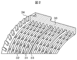
- FIG. 2 is a perspective view showing a part of the labyrinth seal 30 of the balance piston 11 part of the centrifugal compressor 20 shown in FIG.
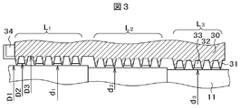
- FIG. 3 is a meridional section (longitudinal section) of the labyrinth seal 30 shown in FIG.
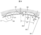
- FIG. 4 is a cross-sectional view (transverse cross section) perpendicular to the axis of 30 parts of the labyrinth seal. 2 and 3, the left side is the upstream side of the leakage flow, and the right side is the downstream side of the leakage flow.
- a labyrinth seal 30 is concentrically disposed on the rotary shaft 2 so as to face the balance piston 11 of the rotor 4.
- the portion of the balance piston 11 facing the labyrinth seal 30 has its outer diameter changed stepwise in three steps. That is, the balance piston diameter d1 on the upstream side is the largest, the balance piston diameter d3 on the downstream side is the smallest, and the intermediate balance piston diameter d2 is an intermediate value.
- a labyrinth seal stage, for example, L1 is formed corresponding to a portion where the diameter of the balance piston 11 is constant, for example, d1.
- a plurality of grooves are formed by ring-shaped parallel teeth (labyrinth fins) 31.
- eight labyrinth fins 31 are formed at equal intervals in the axial direction, thereby forming seven labyrinth grooves in the axial direction.
- the groove formed between the labyrinth fins 31 is changed in depth in the circumferential direction as shown in FIG. 4, and a plurality of pockets 32 are formed by the partition portion 33.
- the labyrinth seal 30 is shown in a plurality of divided shapes, but may be integrally formed in a cylindrical shape.
- the innermost diameter of the labyrinth seal fin 31 protrudes slightly toward the inner diameter side from the inner diameter side end of the partition portion 33 that forms the pocket 32. Moreover, the circumferential distance becomes narrow as the pocket 32 goes to the radial direction outer side. Further, the axial position of the pocket 32 is shifted by about 1/2 pitch in the circumferential direction every time the grooves formed by the labyrinth fin 31 move in a line in the axial direction.
- the meridional cross-sectional shape of the pocket 32 is trapezoidal.
- the labyrinth seal stage L1 will be described as an example.
- the outer diameter of the balance piston 11 is d1.
- the depth of the pocket 32 is about 10 to 30 times the seal gap ⁇ c. That is, assuming that the maximum diameter of the pocket 32 is D3, (D3-D1) / 2 ⁇ (10 to 30) ⁇ ⁇ c. The reason for this is that while the amount of leaked gas flowing into the pocket 32 is suppressed, the gas once inside the pocket 32 does not flow in the circumferential direction but stays in the pocket 32 and is compressed in accordance with the radial displacement of the rotor 4. This is because the damping effect can be exhibited.
- the labyrinth fin 31 has a triangular shape in cross section, and a portion with low strength of the labyrinth fin 31 is provided, so that even if the labyrinth fin 31 contacts the balance piston 11, only the labyrinth fin 31 is consumed. This is to prevent the rotor 4 from being damaged while not affecting the pocket 32 and the partition portion 33. If the inner diameter of the partition portion 33 is further increased, the communication area between the pockets 32 increases, and the damping effect may be reduced.
- the labyrinth seal stages L1 to L3 are provided in three stages, and the diameter of the opposing balance piston 11 is made smaller toward the downstream side of the leakage flow.
- the seal gap ⁇ c between the labyrinth fin 31 and the balance piston 11 is made substantially the same in any of the labyrinth stages L1 to L3.
- the seal area obtained by multiplying the seal gap ⁇ c by the entire circumferential length ( ⁇ d) of the balance piston 11 becomes smaller as it goes to the downstream labyrinth stage, so that the amount of leakage is reduced and the fluid is reduced. The effect of increasing the stability is produced.
- the pocket 32 will be described with reference to FIG. As described above, the depth (D3-D2) / 2 of the pocket 32 is approximately 10 to 30 times the seal gap ⁇ c, and the difference between the inner diameter of the partition 33 and the tip of the labyrinth fin 31 (D2-D1) / 2 is approximately 1 to 5 times the seal gap ⁇ c.
- the circumferential length of the pocket 32 is ⁇ in the circumferential angle, and the pocket 32 is substantially equally arranged in the circumferential direction with the inner circumferential side distal end length B of the partition portion 33 interposed therebetween.
- the pocket 32 is formed by moving in the circumferential direction of the labyrinth seal 30 while rotating the rotating shaft 51 of the turning blade 50 as shown by a one-dot chain line in FIG. Since the radius of the turning tool 50 is R, the shape of the pocket 32 on both sides in the circumferential direction has the same radius of curvature R as the radius of the turning tool 50. With such a shape of the pocket 32, the labyrinth seal 30 having a plurality of pockets 32 in the circumferential direction can be manufactured by machining by attaching the turning tool 50 to the NC machine tool.
- the broken line in FIG. 4 shows the shape of the pocket 32 in the groove formed on the near side or the rear side in the axial direction by one groove with respect to the currently shown groove.
- the positions of the pockets 32 are substantially different by a half pitch in the circumferential direction.
- radial ribs 34 are provided on the upstream side of the labyrinth seal 30. This is because the working gas has a strong swirl velocity component at the exit of the impeller, and therefore when a part of the working gas flows into the labyrinth seal 30 as a leakage flow, the swirl velocity component remains and flows into the labyrinth seal. It is for preventing. If the leakage flow flowing into the labyrinth seal has a large swirl velocity component, unstable vibrations commonly referred to as forward vibrations are likely to occur. In order to suppress this unstable vibration, the circumferential velocity component of the leakage flow flowing into the labyrinth seal is reduced to zero as much as possible.
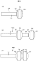
- FIG. 9 is a plan view showing various examples of the turning blade 50 used for machining the pocket 32.
- FIG. 9A shows a turning blade 50 for machining the labyrinth seal 30 for each groove, and a flat portion 54 is formed between the left and right inclined surfaces 52 and 53.
- the left and right inclined surfaces 52 and 53 are inclined according to the meridional cross-sectional shape of the groove of the labyrinth seal 30.
- the flat portion 54 is a parallel surface corresponding to the shape of the bottom of the pocket 32 in the meridional shape of the same groove.
- FIG. 9B shows an example of a turning tool 50a capable of machining two grooves at the same time in order to improve manufacturability.
- the groove portion 55 adjacent to the groove to be processed is formed with an inter-groove portion 55 so as not to be processed.
- FIG. 9C is another example of improving the manufacturability, and is an example of a turning tool 50b capable of machining two grooves at the same time. With this blade, two adjacent grooves are processed simultaneously. Therefore, the circumferential position of the pocket 32 can be changed only in units of two grooves.
- the machining load is doubled compared to the turning tool 50 shown in FIG. 9 (a), and the turning tool 50a has a chucking position.
- the machining position becomes long, and a large cantilever load acts on the turning blade 50a.
- the cantilever load applied to the turning blade 50b can be reduced as compared with the case where the turning blade 50a of FIG. 9B is used.
- FIG. 5 shows the result of measuring the vibration of the rotor 4 by incorporating the labyrinth seal 30 into the balance piston 11 in a high-pressure centrifugal compressor.
- the vibration stability of the rotor 4 is evaluated by the damping rate.
- the horizontal axis represents the operating rotational speed
- the vertical axis represents the damping ratio ⁇ with respect to the rotor natural vibration (first bending).
- FIG. 6 shows a damping rate when a labyrinth seal without pockets, which is conventionally used frequently in the balance piston portion, is incorporated.
- the rated rotational speed of the test centrifugal compressor is 14100 min ⁇ 1 .
- the damping rate for the natural vibration of the bending primary rotor at the rated rotational speed was about 1.4 for the labyrinth seal 30 according to the present invention, but about 0.6 for the conventional labyrinth seal. It can be seen that by using the labyrinth seal of the present invention, the damping rate is improved and therefore the damping characteristics are improved.
- the leakage from the labyrinth seal is set to the same value in both the conventional type and the labyrinth seal according to the present invention, so that the leakage amount is the same as the amount of leakage of the shaft diameter in three stages. The number of cases related to.
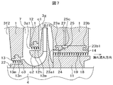
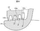
- FIG. 7 and FIG. 8 show meridional cross-sectional views (longitudinal cross-sectional views) when other labyrinth seals included in the single-shaft multistage centrifugal compressor 20 shown in FIG. 1 have a plurality of pockets.
- the labyrinth seal attached to the balance piston 11 portion has a plurality of pockets.
- the eye labyrinth seal 12 provided in the part also has a plurality of pockets.
- the meridional cross-sectional shape of the side plate inlet base c2 is also a stepped step shape having a smaller diameter toward the inlet side. Thereby, the seal area ( ⁇ c ⁇ ⁇ d) can be made smaller toward the downstream side, and the sealing effect can be increased.
- a front stage impeller 3f is arranged upstream of the final stage impeller 3g (see FIG. 1), and an interstage labyrinth is provided between the front stage impeller 3f and the final stage impeller 3g.
- a seal 13 is provided.
- the interstage labyrinth seal 13 is held by the casing 1 and faces the rotor 4 with a seal gap ⁇ c.
- the interstage labyrinth seal 13 is composed of a plurality of annular fins 13 h and a plurality of annular grooves 13 m formed by the plurality of annular fins 13 h, and the gas flowing through the return flow path 7 is a gap between the interstage labyrinth seals 13. Returning to the exit side 3f2 of the preceding impeller 3f through c3 is suppressed.
- a labyrinth seal 14 having a large number of annular labyrinth fins 14 h is arranged between the balance piston 11 and the casing 1.
- the compressed gas discharged from the last stage impeller 3g is prevented from leaking from between the casing 1 and the balance piston 11 to the low pressure portion.
- the labyrinth seal 14 is provided with a shunt hole 27 communicating from the casing 1 side.
- the shunt hole 27 blows a pressure higher than the static pressure at the impeller outlet into the circumferential groove 25 communicating with the labyrinth fins 24 close to the inside of the compressor. Accordingly, a flow from the balance labyrinth 24 to the exit of the impeller 3g can be generated, and the fluid force generated in the labyrinth seal 14 can be stabilized, so that the forward vibration of the rotor 4 is stabilized. .
- the structure of the pocket 32 and the stepped reduction structure of the balance piston diameter can be adopted, which is effective in increasing the damping of the labyrinth seal and reducing the leakage.
- the labyrinth seal protrudes toward the inner diameter side, and the meridian shape is provided with a fin with a narrowed tip, so that the rotor should contact the labyrinth seal. Even so, damage to the rotor can be minimized. Further, since only the seal is worn, the seal gap can be reduced to such an extent that it comes into contact with the rotor when the rotor is fully displaced, so that the leakage of compressed gas can be significantly reduced as compared with the prior art.
- the damping effect can be improved. That is, the partition portions of the plurality of pockets arranged in the circumferential direction act so as to suppress or reduce leakage of leakage fluid from the pockets in the circumferential direction, so that the leakage that remains in the pocket portion when the rotor is displaced in the radial direction.
- the gas is compressed and acts as a damper.
- the effect of suppressing the displacement of the rotor in the rotational direction is obtained, and a fluid stabilizing force is generated in the labyrinth seal portion.
- the circumferential width of the plurality of pockets becomes narrower toward the outer side in the radial direction and the axial longitudinal cross-sectional shape has a larger diameter, the radial resonance frequency of the pocket can be increased, so that the seal constant can be increased. The influence of the frequency characteristics to be exerted can be eliminated as much as possible.
- the meridional cross-sectional shape (longitudinal cross-sectional shape) of the pocket is the same trapezoidal shape as the groove of the labyrinth seal. Since it is processed, the pocket can be manufactured only by turning, improving the workability of the pocket.
- the labyrinth seal has a step structure, and the diameter on the rotor side is made smaller toward the downstream side of the leakage flow according to each stage of the labyrinth seal. If it is squeezed, the fluid stability can be increased.
- centrifugal compressor capable of preventing unstable vibration of the rotor while suppressing seal leakage, and capable of stable operation even under high speed and high pressure conditions.
Landscapes
- Engineering & Computer Science (AREA)
- General Engineering & Computer Science (AREA)
- Mechanical Engineering (AREA)
- Structures Of Non-Positive Displacement Pumps (AREA)
- Sealing Using Fluids, Sealing Without Contact, And Removal Of Oil (AREA)
Description
る。
(1)シール本来の作用として、漏れ量が可能な限り少ない。
(2)不安定流体力が少ない、または不安定流体力を安定力に変えることができる。
(3)万一、ロータと接触してもロータ側の損傷を軽微にできる。
(4)製作性が高く、作りやすい。
そのため、上記特許文献1に記載の従来のラビリンスシールでは、周方向に多数分割してセグメントを形成してラビリンスに流入した漏れ流れが周方向に流出するのを防止している。しかしながら、ラビリンスシールの軸方向形状は従来多用されている形状であり、ダンピングと漏れ量低減を両立させるためにロータ径を階段状に減少させることについては、考慮されていない。しかも多数のセグメントに分割した結果、微小なシール隙間を確保して精度良く製作するためには、工数が増加する。
Claims (6)
- ケーシングと、このケーシングに回転可能に保持され羽根車を取り付けたロータと、前記ケーシングに取り付けられ、前記ロータに対向して配置されるラビリンスシールとを備え、前記羽根車が回転して気体を圧縮する遠心圧縮機において、
前記ラビリンスシールは少なくとも羽根車の吸込み部もしくは前記ロータの推力をバランスさせるバランスピストンのいずれかに設けられたものであり、このラビリンスシールに対向する前記ロータの径を階段状に増加または減少させ、前記ラビリンスシールは軸方向に複数個の溝から形成されており、各溝とも周方向に複数のポケットが形成されていることを特徴とする遠心圧縮機。 - 請求項1記載の遠心圧縮機において、前記ラビリンスシールの複数の溝に形成したポケットの周方向位置を、溝ごとに異ならせていることを特徴とする遠心圧縮機。
- 請求項1または2に記載の遠心圧縮機において、前記ラビリンスシールの溝形状は子午面断面において台形状をしており、各溝に形成するポケットは、旋削用刃物をこの溝の周方向に移動させて旋削加工して製作されたものであることを特徴とする遠心圧縮機。
- 請求項1ないし3のいずれか1項に記載の遠心圧縮機において、前記ラビリンスシールの上流側の端面に、放射状の突起を形成したことを特徴とする遠心圧縮機。
- 請求項1に記載の遠心圧縮機において、前記ラビリンスシールは複数のほぼ平行に形成されたラビリンスフィンにより前記複数の溝が形成されており、この複数のラビリンスフィンの最内径は前記ポケットの内径側端部径より小さく形成されており、複数の前記ポケットは半径方向外側に行くにつれその周方向幅が狭まる形状を有することを特徴とする遠心圧縮機。
- 請求項5に記載の遠心圧縮機において、前記ラビリンスシールチップ径と前記ポケットの内径側端部の径との差は、このラビリンスシールが対向する前記ロータとの間で形成するシール隙間の10倍以内であり、前記ポケットの深さはこのシール隙間の10~30倍程度であり、前記ラビリンスシールのラビリンスフィン高さはシール隙間の10~30倍
程度であることを特徴とする遠心圧縮機。
Priority Applications (4)
| Application Number | Priority Date | Filing Date | Title |
|---|---|---|---|
| CN201380050068.4A CN104662306B (zh) | 2012-10-04 | 2013-09-20 | 离心压缩机 |
| RU2015111993A RU2605546C9 (ru) | 2012-10-04 | 2013-09-20 | Центробежный компрессор |
| BR112015007508A BR112015007508A2 (pt) | 2012-10-04 | 2013-09-20 | compressor centrífugo |
| SA515360227A SA515360227B1 (ar) | 2012-10-04 | 2015-04-02 | ضاغط بالطرد المركزي |
Applications Claiming Priority (2)
| Application Number | Priority Date | Filing Date | Title |
|---|---|---|---|
| JP2012-222142 | 2012-10-04 | ||
| JP2012222142A JP6049385B2 (ja) | 2012-10-04 | 2012-10-04 | 遠心圧縮機 |
Publications (1)
| Publication Number | Publication Date |
|---|---|
| WO2014054440A1 true WO2014054440A1 (ja) | 2014-04-10 |
Family
ID=50434770
Family Applications (1)
| Application Number | Title | Priority Date | Filing Date |
|---|---|---|---|
| PCT/JP2013/075497 Ceased WO2014054440A1 (ja) | 2012-10-04 | 2013-09-20 | 遠心圧縮機 |
Country Status (6)
| Country | Link |
|---|---|
| JP (1) | JP6049385B2 (ja) |
| CN (1) | CN104662306B (ja) |
| BR (1) | BR112015007508A2 (ja) |
| RU (1) | RU2605546C9 (ja) |
| SA (1) | SA515360227B1 (ja) |
| WO (1) | WO2014054440A1 (ja) |
Cited By (7)
| Publication number | Priority date | Publication date | Assignee | Title |
|---|---|---|---|---|
| CN105805052A (zh) * | 2014-12-31 | 2016-07-27 | 锦州新锦化机械制造有限公司 | 离心式压缩机平衡盘装置 |
| WO2017080804A1 (en) * | 2015-11-10 | 2017-05-18 | Onesubsea Ip Uk Limited | Axial bearing offloading in fluid processing machines |
| WO2020026584A1 (ja) * | 2018-07-30 | 2020-02-06 | 株式会社日立インダストリアルプロダクツ | 圧縮機 |
| FR3088684A1 (fr) * | 2018-11-21 | 2020-05-22 | Thermodyn | Piston d’equilibrage et d’etancheite, circuit de refroidissement et procede associes |
| CN111457094A (zh) * | 2020-04-10 | 2020-07-28 | 上海理工大学 | 具有分形特性的矩形槽共振阻尼密封结构 |
| US20210215056A1 (en) * | 2018-06-20 | 2021-07-15 | Safran Aircraft Engines | Labyrinth sealing joint for an aircraft turbomachine |
| CN114233649A (zh) * | 2021-11-26 | 2022-03-25 | 中国科学院工程热物理研究所 | 一种超临界二氧化碳压缩机 |
Families Citing this family (9)
| Publication number | Priority date | Publication date | Assignee | Title |
|---|---|---|---|---|
| DE102014224757A1 (de) * | 2014-12-03 | 2016-06-09 | Robert Bosch Gmbh | Verdichter mit einem Dichtkanal |
| JP2017160861A (ja) | 2016-03-10 | 2017-09-14 | 株式会社日立製作所 | ターボ機械 |
| CN106949245B (zh) * | 2017-03-07 | 2018-04-17 | 西安交通大学 | 一种自止旋收敛型旋转密封结构 |
| CN107524637A (zh) * | 2017-07-24 | 2017-12-29 | 西北工业大学 | 一种跨音速轴流风扇叶片角向缝机匣处理结构设计 |
| EP3903924A4 (en) * | 2018-12-26 | 2022-06-22 | M. Technique Co., Ltd. | FLUID TREATMENT DEVICE |
| WO2020176339A1 (en) * | 2019-02-25 | 2020-09-03 | Danfoss A/S | Abradable labyrinth seal for refrigerant compressors |
| CN112796841B (zh) * | 2020-12-25 | 2022-03-15 | 东方电气集团东方汽轮机有限公司 | 一种减少过桥汽封漏汽量的结构 |
| CN113431902A (zh) * | 2021-05-13 | 2021-09-24 | 东南大学 | 一种流动调控型减振密封装置 |
| CN115839262B (zh) * | 2021-09-18 | 2025-05-23 | 中国航发商用航空发动机有限责任公司 | 封严篦齿结构和封严结构 |
Citations (7)
| Publication number | Priority date | Publication date | Assignee | Title |
|---|---|---|---|---|
| JPH08505462A (ja) * | 1993-01-08 | 1996-06-11 | ザ、テクサス、エイアンドエム、ユーニヴァーサティ、システィム | 圧力ダンパーシール |
| JPH1113688A (ja) * | 1997-06-23 | 1999-01-19 | Hitachi Ltd | ラビリンスシール装置及びそれを備えた流体機械 |
| JP2002228014A (ja) * | 2001-02-05 | 2002-08-14 | Mitsubishi Heavy Ind Ltd | ラビリンスシール |
| JP2008190487A (ja) * | 2007-02-07 | 2008-08-21 | Hitachi Plant Technologies Ltd | 遠心型流体機械 |
| JP2010007611A (ja) * | 2008-06-30 | 2010-01-14 | Hitachi Ltd | ターボ機械 |
| WO2011122092A1 (ja) * | 2010-03-30 | 2011-10-06 | 三菱重工業株式会社 | タービン |
| JP2012072736A (ja) * | 2010-09-29 | 2012-04-12 | Kobe Steel Ltd | 回転機械の軸封装置 |
Family Cites Families (6)
| Publication number | Priority date | Publication date | Assignee | Title |
|---|---|---|---|---|
| RU2133879C1 (ru) * | 1996-04-10 | 1999-07-27 | Акционерное общество "Сумское машиностроительное научно-производственное объединение им.М.В.Фрунзе" | Система уплотнений турбокомпрессора |
| US5927720A (en) * | 1997-11-03 | 1999-07-27 | Carrier Corporation | Two-piece labyrinth seal for a centrifugal compressor balance piston |
| JP2009052434A (ja) * | 2007-08-24 | 2009-03-12 | Hitachi Plant Technologies Ltd | 遠心圧縮機 |
| RU93474U1 (ru) * | 2008-09-02 | 2010-04-27 | Вазген Сергеевич Багдасарян | Устройство для исключения перетечек в газотурбинных установках и компрессорах |
| JP2012007594A (ja) * | 2010-06-28 | 2012-01-12 | Mitsubishi Heavy Ind Ltd | シール装置及びこれを備えた流体機械 |
| IT1403222B1 (it) * | 2010-12-30 | 2013-10-17 | Nuovo Pignone Spa | Sistemi e metodi per rastremazione del rompi-vortice |
-
2012
- 2012-10-04 JP JP2012222142A patent/JP6049385B2/ja active Active
-
2013
- 2013-09-20 CN CN201380050068.4A patent/CN104662306B/zh not_active Expired - Fee Related
- 2013-09-20 RU RU2015111993A patent/RU2605546C9/ru not_active IP Right Cessation
- 2013-09-20 BR BR112015007508A patent/BR112015007508A2/pt not_active IP Right Cessation
- 2013-09-20 WO PCT/JP2013/075497 patent/WO2014054440A1/ja not_active Ceased
-
2015
- 2015-04-02 SA SA515360227A patent/SA515360227B1/ar unknown
Patent Citations (7)
| Publication number | Priority date | Publication date | Assignee | Title |
|---|---|---|---|---|
| JPH08505462A (ja) * | 1993-01-08 | 1996-06-11 | ザ、テクサス、エイアンドエム、ユーニヴァーサティ、システィム | 圧力ダンパーシール |
| JPH1113688A (ja) * | 1997-06-23 | 1999-01-19 | Hitachi Ltd | ラビリンスシール装置及びそれを備えた流体機械 |
| JP2002228014A (ja) * | 2001-02-05 | 2002-08-14 | Mitsubishi Heavy Ind Ltd | ラビリンスシール |
| JP2008190487A (ja) * | 2007-02-07 | 2008-08-21 | Hitachi Plant Technologies Ltd | 遠心型流体機械 |
| JP2010007611A (ja) * | 2008-06-30 | 2010-01-14 | Hitachi Ltd | ターボ機械 |
| WO2011122092A1 (ja) * | 2010-03-30 | 2011-10-06 | 三菱重工業株式会社 | タービン |
| JP2012072736A (ja) * | 2010-09-29 | 2012-04-12 | Kobe Steel Ltd | 回転機械の軸封装置 |
Cited By (13)
| Publication number | Priority date | Publication date | Assignee | Title |
|---|---|---|---|---|
| CN105805052A (zh) * | 2014-12-31 | 2016-07-27 | 锦州新锦化机械制造有限公司 | 离心式压缩机平衡盘装置 |
| WO2017080804A1 (en) * | 2015-11-10 | 2017-05-18 | Onesubsea Ip Uk Limited | Axial bearing offloading in fluid processing machines |
| US20210215056A1 (en) * | 2018-06-20 | 2021-07-15 | Safran Aircraft Engines | Labyrinth sealing joint for an aircraft turbomachine |
| US11692450B2 (en) * | 2018-06-20 | 2023-07-04 | Safran Aircraft Engines | Labyrinth sealing joint for an aircraft turbomachine |
| WO2020026584A1 (ja) * | 2018-07-30 | 2020-02-06 | 株式会社日立インダストリアルプロダクツ | 圧縮機 |
| FR3088684A1 (fr) * | 2018-11-21 | 2020-05-22 | Thermodyn | Piston d’equilibrage et d’etancheite, circuit de refroidissement et procede associes |
| JP2022506407A (ja) * | 2018-11-21 | 2022-01-17 | サーモダイン・エスエイエス | バランスシールピストン、並びに関連する冷却回路及び方法 |
| JP7117458B2 (ja) | 2018-11-21 | 2022-08-12 | サーモダイン・エスエイエス | バランスシールピストン、並びに関連する冷却回路及び方法 |
| WO2020104061A1 (en) * | 2018-11-21 | 2020-05-28 | Thermodyn | Balancing and sealing piston, and associated cooling circuit and method |
| US12152604B2 (en) | 2018-11-21 | 2024-11-26 | Thermodyn Sas | Balancing and sealing piston, and associated cooling circuit and method |
| CN111457094A (zh) * | 2020-04-10 | 2020-07-28 | 上海理工大学 | 具有分形特性的矩形槽共振阻尼密封结构 |
| CN114233649A (zh) * | 2021-11-26 | 2022-03-25 | 中国科学院工程热物理研究所 | 一种超临界二氧化碳压缩机 |
| CN114233649B (zh) * | 2021-11-26 | 2024-05-28 | 中国科学院工程热物理研究所 | 一种超临界二氧化碳压缩机 |
Also Published As
| Publication number | Publication date |
|---|---|
| RU2605546C2 (ru) | 2016-12-20 |
| RU2015111993A (ru) | 2016-10-20 |
| CN104662306B (zh) | 2017-06-30 |
| BR112015007508A2 (pt) | 2017-07-04 |
| RU2605546C9 (ru) | 2017-04-27 |
| SA515360227B1 (ar) | 2016-12-18 |
| JP6049385B2 (ja) | 2016-12-21 |
| JP2014074360A (ja) | 2014-04-24 |
| CN104662306A (zh) | 2015-05-27 |
Similar Documents
| Publication | Publication Date | Title |
|---|---|---|
| JP6049385B2 (ja) | 遠心圧縮機 | |
| JP2010038114A (ja) | 遠心圧縮機 | |
| RU2616428C2 (ru) | Лабиринтное уплотнение со спиральной и смешанной спирально-цилиндрической конфигурацией с высокой демпфирующей способностью | |
| CN104105886B (zh) | 回转机械 | |
| CN104813082B (zh) | 密封装置以及旋转机械 | |
| JP2011515622A (ja) | ターボ機械の可動のブレード付きホイールのためのケーシング | |
| WO2014077058A1 (ja) | 回転機械 | |
| WO2012129475A2 (en) | Interlocking hole pattern seal | |
| JP5299150B2 (ja) | 遠心圧縮機 | |
| JP2017514069A (ja) | スクリューマシンの圧縮ブロック用のロータ対 | |
| WO2018061651A1 (ja) | シール機構、回転機械 | |
| JP7211947B2 (ja) | ポンプシーリング | |
| JP2014238066A (ja) | 回転機械 | |
| US9004857B2 (en) | Barrel-shaped centrifugal compressor | |
| WO2018155458A1 (ja) | 遠心回転機械 | |
| CN118548227B (zh) | 旋转机器 | |
| JP2019002361A (ja) | ターボ機械 | |
| JP2009052434A (ja) | 遠心圧縮機 | |
| JP2023150035A (ja) | 遠心回転機械 | |
| JP2020133600A (ja) | 遠心圧縮機 | |
| WO2018110695A1 (ja) | 軸シール装置、及び回転機械 | |
| WO2013115361A1 (ja) | シール構造及びこれを備えた回転機械 | |
| JP2017155631A (ja) | 遠心回転機械 | |
| KR101473425B1 (ko) | 유입공이 형성된 임펠러를 구비한 터보 압축기 | |
| KR20110101982A (ko) | 쉬라우드 스플리터를 장착한 임펠러를 구비한 터보 압축기 |
Legal Events
| Date | Code | Title | Description |
|---|---|---|---|
| 121 | Ep: the epo has been informed by wipo that ep was designated in this application |
Ref document number: 13843572 Country of ref document: EP Kind code of ref document: A1 |
|
| ENP | Entry into the national phase |
Ref document number: 2015111993 Country of ref document: RU Kind code of ref document: A |
|
| NENP | Non-entry into the national phase |
Ref country code: DE |
|
| REG | Reference to national code |
Ref country code: BR Ref legal event code: B01A Ref document number: 112015007508 Country of ref document: BR |
|
| 122 | Ep: pct application non-entry in european phase |
Ref document number: 13843572 Country of ref document: EP Kind code of ref document: A1 |
|
| ENP | Entry into the national phase |
Ref document number: 112015007508 Country of ref document: BR Kind code of ref document: A2 Effective date: 20150402 |