WO2014054346A1 - 複合分離膜 - Google Patents
複合分離膜 Download PDFInfo
- Publication number
- WO2014054346A1 WO2014054346A1 PCT/JP2013/072154 JP2013072154W WO2014054346A1 WO 2014054346 A1 WO2014054346 A1 WO 2014054346A1 JP 2013072154 W JP2013072154 W JP 2013072154W WO 2014054346 A1 WO2014054346 A1 WO 2014054346A1
- Authority
- WO
- WIPO (PCT)
- Prior art keywords
- membrane
- porous support
- spae
- solvent
- support membrane
- Prior art date
- Legal status (The legal status is an assumption and is not a legal conclusion. Google has not performed a legal analysis and makes no representation as to the accuracy of the status listed.)
- Ceased
Links
- 0 Cc1c(*)cc(*c(cc2)cc(*)c2Clc2ccc(*c(cc3)ccc3NC)cc2)cc1 Chemical compound Cc1c(*)cc(*c(cc2)cc(*)c2Clc2ccc(*c(cc3)ccc3NC)cc2)cc1 0.000 description 1
Images


Classifications
-
- B—PERFORMING OPERATIONS; TRANSPORTING
- B01—PHYSICAL OR CHEMICAL PROCESSES OR APPARATUS IN GENERAL
- B01D—SEPARATION
- B01D71/00—Semi-permeable membranes for separation processes or apparatus characterised by the material; Manufacturing processes specially adapted therefor
- B01D71/06—Organic material
- B01D71/66—Polymers having sulfur in the main chain, with or without nitrogen, oxygen or carbon only
- B01D71/68—Polysulfones; Polyethersulfones
-
- B—PERFORMING OPERATIONS; TRANSPORTING
- B01—PHYSICAL OR CHEMICAL PROCESSES OR APPARATUS IN GENERAL
- B01D—SEPARATION
- B01D61/00—Processes of separation using semi-permeable membranes, e.g. dialysis, osmosis or ultrafiltration; Apparatus, accessories or auxiliary operations specially adapted therefor
- B01D61/02—Reverse osmosis; Hyperfiltration ; Nanofiltration
- B01D61/025—Reverse osmosis; Hyperfiltration
-
- B—PERFORMING OPERATIONS; TRANSPORTING
- B01—PHYSICAL OR CHEMICAL PROCESSES OR APPARATUS IN GENERAL
- B01D—SEPARATION
- B01D67/00—Processes specially adapted for manufacturing semi-permeable membranes for separation processes or apparatus
- B01D67/0002—Organic membrane manufacture
-
- B—PERFORMING OPERATIONS; TRANSPORTING
- B01—PHYSICAL OR CHEMICAL PROCESSES OR APPARATUS IN GENERAL
- B01D—SEPARATION
- B01D67/00—Processes specially adapted for manufacturing semi-permeable membranes for separation processes or apparatus
- B01D67/0081—After-treatment of organic or inorganic membranes
- B01D67/0093—Chemical modification
-
- B—PERFORMING OPERATIONS; TRANSPORTING
- B01—PHYSICAL OR CHEMICAL PROCESSES OR APPARATUS IN GENERAL
- B01D—SEPARATION
- B01D67/00—Processes specially adapted for manufacturing semi-permeable membranes for separation processes or apparatus
- B01D67/0081—After-treatment of organic or inorganic membranes
- B01D67/0095—Drying
-
- B—PERFORMING OPERATIONS; TRANSPORTING
- B01—PHYSICAL OR CHEMICAL PROCESSES OR APPARATUS IN GENERAL
- B01D—SEPARATION
- B01D69/00—Semi-permeable membranes for separation processes or apparatus characterised by their form, structure or properties; Manufacturing processes specially adapted therefor
- B01D69/02—Semi-permeable membranes for separation processes or apparatus characterised by their form, structure or properties; Manufacturing processes specially adapted therefor characterised by their properties
-
- B—PERFORMING OPERATIONS; TRANSPORTING
- B01—PHYSICAL OR CHEMICAL PROCESSES OR APPARATUS IN GENERAL
- B01D—SEPARATION
- B01D69/00—Semi-permeable membranes for separation processes or apparatus characterised by their form, structure or properties; Manufacturing processes specially adapted therefor
- B01D69/08—Hollow fibre membranes
-
- B—PERFORMING OPERATIONS; TRANSPORTING
- B01—PHYSICAL OR CHEMICAL PROCESSES OR APPARATUS IN GENERAL
- B01D—SEPARATION
- B01D69/00—Semi-permeable membranes for separation processes or apparatus characterised by their form, structure or properties; Manufacturing processes specially adapted therefor
- B01D69/12—Composite membranes; Ultra-thin membranes
- B01D69/1216—Three or more layers
-
- B—PERFORMING OPERATIONS; TRANSPORTING
- B01—PHYSICAL OR CHEMICAL PROCESSES OR APPARATUS IN GENERAL
- B01D—SEPARATION
- B01D71/00—Semi-permeable membranes for separation processes or apparatus characterised by the material; Manufacturing processes specially adapted therefor
- B01D71/06—Organic material
- B01D71/52—Polyethers
- B01D71/521—Aliphatic polyethers
- B01D71/5211—Polyethylene glycol or polyethyleneoxide
-
- B—PERFORMING OPERATIONS; TRANSPORTING
- B01—PHYSICAL OR CHEMICAL PROCESSES OR APPARATUS IN GENERAL
- B01D—SEPARATION
- B01D71/00—Semi-permeable membranes for separation processes or apparatus characterised by the material; Manufacturing processes specially adapted therefor
- B01D71/06—Organic material
- B01D71/52—Polyethers
- B01D71/522—Aromatic polyethers
- B01D71/5222—Polyetherketone, polyetheretherketone, or polyaryletherketone
-
- B—PERFORMING OPERATIONS; TRANSPORTING
- B01—PHYSICAL OR CHEMICAL PROCESSES OR APPARATUS IN GENERAL
- B01D—SEPARATION
- B01D71/00—Semi-permeable membranes for separation processes or apparatus characterised by the material; Manufacturing processes specially adapted therefor
- B01D71/06—Organic material
- B01D71/52—Polyethers
- B01D71/522—Aromatic polyethers
- B01D71/5223—Polyphenylene oxide, phenyl ether polymers or polyphenylethers
-
- B—PERFORMING OPERATIONS; TRANSPORTING
- B01—PHYSICAL OR CHEMICAL PROCESSES OR APPARATUS IN GENERAL
- B01D—SEPARATION
- B01D71/00—Semi-permeable membranes for separation processes or apparatus characterised by the material; Manufacturing processes specially adapted therefor
- B01D71/06—Organic material
- B01D71/76—Macromolecular material not specifically provided for in a single one of groups B01D71/08 - B01D71/74
-
- C—CHEMISTRY; METALLURGY
- C02—TREATMENT OF WATER, WASTE WATER, SEWAGE, OR SLUDGE
- C02F—TREATMENT OF WATER, WASTE WATER, SEWAGE, OR SLUDGE
- C02F1/00—Treatment of water, waste water, or sewage
- C02F1/44—Treatment of water, waste water, or sewage by dialysis, osmosis or reverse osmosis
- C02F1/441—Treatment of water, waste water, or sewage by dialysis, osmosis or reverse osmosis by reverse osmosis
-
- C—CHEMISTRY; METALLURGY
- C02—TREATMENT OF WATER, WASTE WATER, SEWAGE, OR SLUDGE
- C02F—TREATMENT OF WATER, WASTE WATER, SEWAGE, OR SLUDGE
- C02F1/00—Treatment of water, waste water, or sewage
- C02F1/44—Treatment of water, waste water, or sewage by dialysis, osmosis or reverse osmosis
- C02F1/442—Treatment of water, waste water, or sewage by dialysis, osmosis or reverse osmosis by nanofiltration
-
- B—PERFORMING OPERATIONS; TRANSPORTING
- B01—PHYSICAL OR CHEMICAL PROCESSES OR APPARATUS IN GENERAL
- B01D—SEPARATION
- B01D2325/00—Details relating to properties of membranes
- B01D2325/14—Membrane materials having negatively charged functional groups
-
- B—PERFORMING OPERATIONS; TRANSPORTING
- B01—PHYSICAL OR CHEMICAL PROCESSES OR APPARATUS IN GENERAL
- B01D—SEPARATION
- B01D2325/00—Details relating to properties of membranes
- B01D2325/30—Chemical resistance
-
- B—PERFORMING OPERATIONS; TRANSPORTING
- B01—PHYSICAL OR CHEMICAL PROCESSES OR APPARATUS IN GENERAL
- B01D—SEPARATION
- B01D61/00—Processes of separation using semi-permeable membranes, e.g. dialysis, osmosis or ultrafiltration; Apparatus, accessories or auxiliary operations specially adapted therefor
- B01D61/02—Reverse osmosis; Hyperfiltration ; Nanofiltration
- B01D61/027—Nanofiltration
-
- B—PERFORMING OPERATIONS; TRANSPORTING
- B01—PHYSICAL OR CHEMICAL PROCESSES OR APPARATUS IN GENERAL
- B01D—SEPARATION
- B01D67/00—Processes specially adapted for manufacturing semi-permeable membranes for separation processes or apparatus
- B01D67/0002—Organic membrane manufacture
- B01D67/0009—Organic membrane manufacture by phase separation, sol-gel transition, evaporation or solvent quenching
- B01D67/0018—Thermally induced processes [TIPS]
-
- Y—GENERAL TAGGING OF NEW TECHNOLOGICAL DEVELOPMENTS; GENERAL TAGGING OF CROSS-SECTIONAL TECHNOLOGIES SPANNING OVER SEVERAL SECTIONS OF THE IPC; TECHNICAL SUBJECTS COVERED BY FORMER USPC CROSS-REFERENCE ART COLLECTIONS [XRACs] AND DIGESTS
- Y02—TECHNOLOGIES OR APPLICATIONS FOR MITIGATION OR ADAPTATION AGAINST CLIMATE CHANGE
- Y02A—TECHNOLOGIES FOR ADAPTATION TO CLIMATE CHANGE
- Y02A20/00—Water conservation; Efficient water supply; Efficient water use
- Y02A20/124—Water desalination
- Y02A20/131—Reverse-osmosis
Definitions
- the present invention relates to a long-life composite separation membrane having excellent separation characteristics and water permeability as a liquid treatment membrane, particularly a nanofiltration membrane and a reverse osmosis membrane, and excellent in chlorine resistance and alkali resistance, and a method for producing the same.
- Nanofiltration membranes and reverse osmosis membranes are film-like structures that are considered to have a pore size on the order of nanometers to angstroms, or that do not have clear pores. Tend to. Therefore, as a nanofiltration membrane and a reverse osmosis membrane, by forming a thin layer of a separation layer having a separation function as thin as possible on the surface of a porous support membrane having excellent mechanical strength and water permeability, high water permeability
- the structure of a composite separation membrane that achieves both high performance and separation properties is preferably used.
- the polymer constituting the separation layer is required to be excellent in chemical durability, particularly chlorine resistance and alkali resistance, from the viewpoint of detergency and stability against long-term use.
- Patent Document 1 discloses a sheet-like composite in which a polyamide thin film crosslinked by interfacial polymerization is formed on the surface of a porous support membrane.
- Patent Document 2 discloses a hollow fiber composite separation membrane in which a thin film of polyamide crosslinked by interfacial polymerization is formed on the surface of a hollow fiber-like porous support membrane.
- Patent Document 3 in a hollow fiber composite separation membrane in which a polyamide thin film crosslinked by interfacial polymerization is formed on the surface of a porous hollow fiber-like support membrane, a fluorine compound is added during the compositing process by interfacial polymerization.
- a technique for forming a hollow fiber composite separation membrane having a more uniform separation layer by providing a step of impregnating a liquid to be contained is also disclosed.
- a synthetic polymer that can be applied to nanofiltration membranes and reverse osmosis membranes other than polyamide-based materials includes polymers having ionic functional groups such as sulfonic acid groups in the molecule.
- a composite separation membrane is prepared by dissolving a sulfonated polyarylene ether in a solvent made of formic acid, and coating the resulting coating solution on the surface of the porous support membrane and drying to form a membrane.
- the nanofiltration membrane and reverse osmosis membrane by the polyamide-based composite separation membrane as in Patent Document 1 are excellent in salt removal and water permeability, but have low chlorine resistance and treat water containing sodium hypochlorite. Is impossible, and chlorine cleaning is also impossible. For this reason, once the supply liquid from which sodium hypochlorite has been removed is desalted by the separation membrane, it is necessary to add sodium hypochlorite again to the filtered water obtained, and the filtration process There is a problem that it is complicated and expensive.
- Patent Document 2 and Patent Document 3 since it is a polyamide-based composite separation membrane, it has a drawback of low chlorine resistance, and in the process of producing a hollow fiber-shaped composite separation membrane, structure formation by an interfacial polymerization reaction is performed. The process to be performed has a problem that it becomes complicated as compared with a flat film or a sheet-like material.
- the composite separation membrane having a sulfonated polyarylene ether (SPAE) as a separation layer as in Patent Document 4 is very excellent in chlorine resistance due to the high chemical stability of the polyarylene ether molecular skeleton, and sodium hypochlorite. Is practically preferable because it can be washed by the above method.
- SPAE sulfonated polyarylene ether
- SPAE can dissolve SPAE because it has a similar chemical structure to polysulfone or polyethersulfone, which is a polymer material of a general porous support membrane. Most solvents can simultaneously dissolve polysulfone or polyethersulfone. When such a solvent is applied as a coating solution to the porous support membrane, the porous support membrane dissolves or significantly swells, resulting in a problem that a composite membrane cannot be obtained.
- the present invention has been made to overcome the above-mentioned problems of the prior art, and an object of the present invention is to provide a composite separation membrane having a separation layer made of SPAE on the surface of the porous support membrane. It is an object of the present invention to provide a film in which the film is firmly adhered and the separation characteristics and water permeability are maintained for a long period of time, and a suitable production method thereof.
- the present inventor firstly, in a composite separation membrane composed of a combination of a polymer constituting a porous support membrane and SPAE constituting a separation membrane, the solvent solubility of each polymer, the composite process, and the performance as a composite separation membrane. was examined.
- polysulfone (PSU) or polyethersulfone (PES) is N-methyl-2-pyrrolidone (NMP), N, N-dimethylacetamide (DMAc), dimethyl sulfoxide (DMSO), N, Good solubility in N-dimethylformamide (DMF), ⁇ -butyrolactone (GBL), and a mixed solvent containing at least one of them (hereinafter referred to as solvent group 1).
- NMP N-methyl-2-pyrrolidone
- DMAc N-dimethylacetamide
- DMSO dimethyl sulfoxide
- GBL ⁇ -butyrolactone
- solvent group 1 a mixed solvent containing at least one of them
- the SPAE that constitutes the separation membrane also shows good solubility in the solvent group 1
- the use of the solvent group 1 as the main component of the coating solution has been It was impossible.
- examples of other engineering polymers generally used for porous support membranes include polyvinylidene fluoride (PVDF) and polyetherimide (PEI). These polymers also include the above-mentioned polysulfone and polyethersulfone. Since it dissolves in the solvent group 1 as well, the same problem occurs.
- solvent group 2 alkylene glycol alkyl ethers
- the solubility of the solvent group 2 in SPAE is often not always good.
- the affinity for the porous support membrane tends to be high, and the porous support membrane is not swollen, but is significantly swollen, There is a problem that the mechanical strength is lowered.
- the porous support membrane is significantly swollen, which is not preferable.
- SPAE having a chemical structure suitable for composite separation membrane applications solvent solubility is further limited.
- SPAE that has been molecularly designed by direct copolymerization has been developed from the viewpoint of stably obtaining higher ion separation characteristics in nanofiltration and reverse osmosis.
- a SPAE having a chemical structure having a rigid molecular skeleton and a strong cohesive force of the hydrophobic segment is preferable because it is excellent in mechanical properties, hardly swells, and provides high ion separation properties.
- a SPAE having a repeating structure of a hydrophobic segment represented by the following formula (I) and a repeating unit of a hydrophilic segment represented by the following formula (II) has a rigid molecular skeleton, a hydrophobic segment ( I) Excellent cohesive force due to its high cohesive force, and can form a film with little swelling, so it is suitable for nanofiltration and reverse osmosis applications, but it can be dissolved in solvent group 1. Even so, the solvent group 2 has a problem of hardly exhibiting solubility.
- m and n each represent a natural number of 1 or more
- R 1 and R 2 represent —SO 3 M or —SO 3 H
- M represents a metal element
- a sulfonated polyarylene ether copolymer The sulfonation rate expressed as a percentage ratio of the number of repetitions of formula (II) to the sum of the number of repetitions of formula (I) and formula (II) is greater than 5% and less than 80% .
- the solvent group 2 cannot be used as a coating solvent.
- the powerful solvent group 1 must be used.
- a porous support membrane insoluble in the solvent group 1 is essential, and the above-mentioned known porous support membrane cannot be used.
- the present inventors searched for a polymer that is insoluble in the solvent group 1 and is suitable for the porous support membrane of the composite separation membrane, and made a trial production of a composite separation membrane coated with the above-mentioned SPAE.
- the porous support membrane preferably supports the thin film of the separation layer under the pressure during the separation operation (0.1 to 8.0 MPa), and can be used stably for a long period of time.
- the polymer has excellent mechanical strength and chemical durability. It is an indispensable condition to use. Furthermore, it is possible to easily obtain a membrane having a pore size comparable to that of an ultrafiltration membrane, which has an appropriate solvent solubility and is suitable as a porous support membrane for a composite separation membrane by a known wet or dry wet membrane formation method. preferable.
- a polymer having a high glass transition temperature is preferred.
- an amorphous polymer is preferred.
- a porous support film using an amorphous aromatic polymer is preferable.
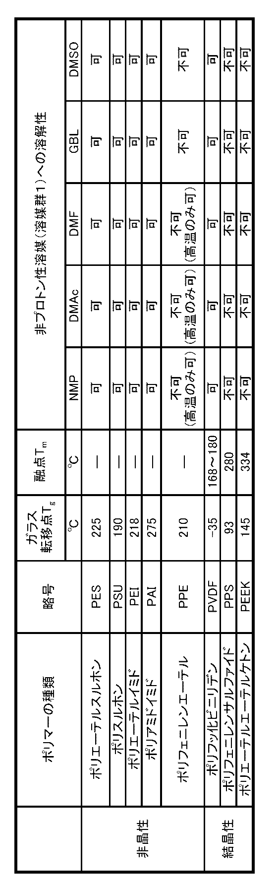
- Table 1 shows the solubility of known typical polymers in aprotic solvents.
- polyphenylene sulfide (PPS) and polycrystalline polymers are known as crystalline polymers having excellent mechanical properties and chemical durability.
- PES polyphenylene sulfide
- PEEK ether ether ketone
- PES polyetherimide
- PSU polysulfone
- PES polyethersulfone
- PVDF Polyvinylidene fluoride
- polyphenylene ether among known amorphous aromatic polymers. It has been found that polyphenylene ether does not dissolve in solvent group 1 or exhibits limited solubility, and is a polymer suitable as a porous support membrane in order to achieve the object of the present invention.
- polyphenylene ether is completely insoluble in dimethyl sulfoxide (DMSO) and ⁇ -butyrolactone (GBL) in solvent group 1 of aprotic solvents.
- DMSO dimethyl sulfoxide
- GBL ⁇ -butyrolactone
- NMP N-methyl-2-pyrrolidone
- DMAc dimethylacetamide
- DMF N, N-dimethylformamide
- the polyphenylene ether porous support membrane does not swell excessively by the solvent, and therefore, at a relatively high temperature in the drying process after coating. It was found that even when the solvent was quickly dried, the film was hardly broken or the performance was not lowered. This is a great advantage in the manufacturing method of the composite separation membrane, and even if the solvent group 1 has a relatively high boiling point (150 to 210 ° C.), it is excellent if the solvent is quickly dried at a high temperature (100 ° C. or higher). It is possible to stably and easily form a dense SPAE separation layer having separability.
- the solubility of the solvent group 1 in SPAE is good, the stability of the solution can be maintained even when a desired non-solvent is added to a considerable degree, for example, 50% by weight or more. It was found that a composite separation membrane suitable for nanofiltration and reverse osmosis applications can be obtained by controlling the vapor pressure and surface tension of the material to desired conditions.
- a composite separation membrane comprising a sulfonated polyarylene ether copolymer having a repeating structure.
- the sulfonated polyarylene ether copolymer comprises a repeating structure of a hydrophobic segment represented by the following formula (IV) and a hydrophilic segment represented by the following formula (V).
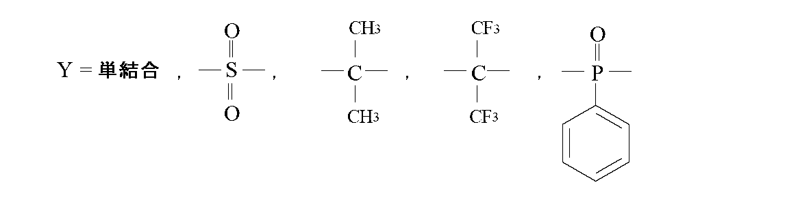
- the composite separation membrane according to (1) In the above formula, And And And And And The same Y and W are not selected, a and b each represent a natural number of 1 or more, R 1 and R 2 represent —SO 3 M or —SO 3 H, M represents a metal element, Sulfonation rate expressed as a percentage of the number of repetitions of formula (V) to the total number of repetitions of formula (IV) and formula (V) in the sulfonated polyarylene ether copolymer is from 5% Is larger than 80%.
- the sulfonated polyarylene ether copolymer has a repeating structure of a hydrophobic segment represented by the following formula (I) and a hydrophilic segment represented by the following formula (II).
- the composite separation membrane according to (1) In the above formula, m and n each represent a natural number of 1 or more, R 1 and R 2 represent —SO 3 M or —SO 3 H, M represents a metal element, and a sulfonated polyarylene ether copolymer
- the sulfonation rate expressed as a percentage ratio of the number of repetitions of formula (II) to the sum of the number of repetitions of formula (I) and formula (II) is greater than 5% and less than 80% .
- the composite separation membrane of the present invention is provided with a separation layer made of a specific SPAE on the surface of a porous support membrane containing polyphenylene ether as a main component, so that the adhesion between the porous support membrane and the separation layer is extremely good.
- the nanofiltration membrane and the reverse osmosis membrane have excellent separation characteristics and water permeability for a long period of time, and are excellent in chlorine resistance and alkali resistance, and have a long life.
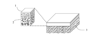
- FIG. 1 shows a schematic diagram (flat membrane) of the composite separation membrane of the present invention.
- FIG. 2 shows a schematic diagram (hollow fiber membrane) of the composite separation membrane of the present invention.
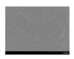
- FIG. 3 is an SEM (Scanning Electron Microscope) image of the cross section of the composite separation membrane of Example 1.
- FIG. 4 is an enlarged SEM image of an outer layer portion of the membrane section of the composite separation membrane of Example 1.
- FIG. 5 is an enlarged SEM image of the membrane surface of the composite separation membrane of Example 1.
- the composite separation membrane of the present invention has a separation layer on the surface of a porous support membrane, the porous support membrane contains polyphenylene ether as a main component, and the separation layer has a specific repeating structure. It is characterized by comprising a copolymer.
- the composite separation membrane of the present invention is suitable as a liquid treatment membrane, particularly a nanofiltration membrane and a reverse osmosis membrane.
- Nanofiltration membranes and reverse osmosis membranes are separation membranes having a dense film-like separation layer that has a pore size of several nanometers or less or is considered to have no clear pores, and has a low molecular weight such as glucose. These are used when organic molecules and solutes of inorganic salts are separated from the solution.
- the nanofiltration membrane has a larger pore size than the reverse osmosis membrane, and is a liquid treatment membrane that can partially remove low molecular weight organic molecules, monovalent ions and multivalent ions.
- the reverse osmosis membrane has a pore size larger than that of the nanofiltration membrane. It is a liquid processing membrane that is small and capable of almost completely separating and removing monovalent ions such as sodium ions.
- the composite separation membrane of the present invention is about the size of the target fraction substance on the surface of a porous support membrane made of a hydrophobic polymer having a pore (diameter is approximately 10 nm to several hundred nm) sufficiently larger than the size of the target fraction substance. It is a membrane in which a thin film made of a polymer having the above separation characteristics is formed. It is composed of at least two types of polymers, and it is possible to clearly distinguish each polymer component constituting the separation layer and the porous support membrane. it can. In the case of a flat membrane as shown in FIG. 1, a porous support membrane 2 is placed on a nonwoven fabric 3 such as polyester, and a thin film of the separation layer 1 is further formed on the surface of the porous support membrane 2.
- a thin film of the separation layer 1 is formed on the hollow fiber-like porous support membrane 2.
- the thin film refers to a film having a thickness of about 5 nm to 1 ⁇ m.
- the thickness of the porous support membrane is sufficiently thicker than the thin film and is at least 5 ⁇ m or more.
- an asymmetric membrane exists as a membrane structure different from the composite separation membrane of the present invention.
- the asymmetric membrane is a membrane obtained by coagulating a membrane-forming stock solution by a phase separation method, and is controlled so that the surface layer of the membrane is dense and the inner layer side of the membrane is porous.
- the asymmetric membrane may be composed of one or more types of polymer components using a polymer blend method or the like, but is basically a membrane obtained only by controlling the gradient of the polymer density in the membrane. In the separation layer and the porous support layer, the polymer components are the same.
- the composite separation membrane is more preferable as the membrane structure because the structure and thickness of the porous support membrane and the structure and thickness of the separation layer can be independently controlled, and the water permeability is higher.
- porous support membrane of the composite separation membrane of the present invention the separation membrane, and the production method thereof will be described in detail.
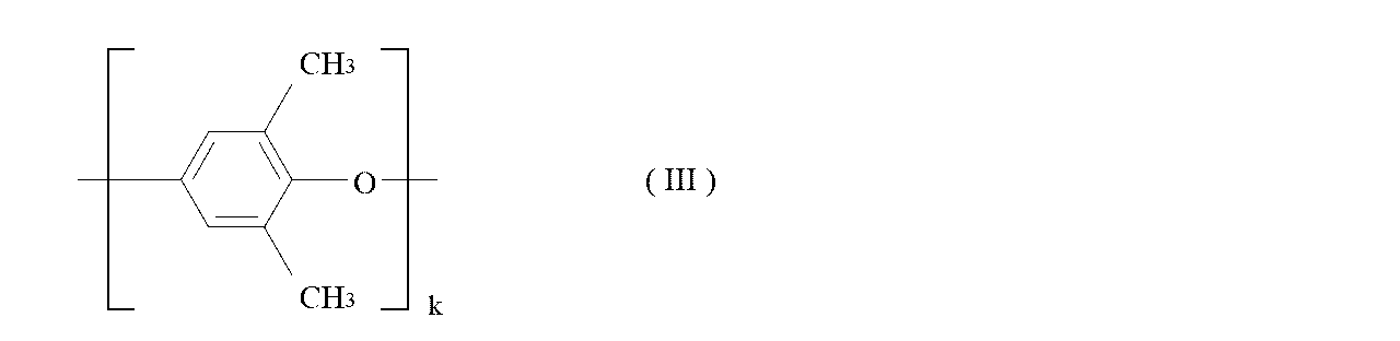
- the polyphenylene ether used for the porous support membrane of the composite separation membrane of the present invention is represented by the following formula (III).
- k represents a natural number of 1 or more.
- the number average molecular weight of the polyphenylene ether is preferably 5,000 or more and 500,000 or less. If it is this range, it can melt
- polymer blends of various polymers such as polystyrene, which is known to be completely compatible with the above polyphenylene ether, with polyphenylene ether May be performed. Or you may include a filler in polyphenylene ether.
- an ionic surfactant, a nonionic surfactant, or a hydrophilic polymer such as polyethylene glycol or polyvinyl pyrrolidone may be included.
- the proportion of polyphenylene ether constituting the porous support membrane is preferably 50% by mass or more.
- the polyphenylene ether having higher mechanical strength and chemical resistance are retained without being attacked by the solvent group 1 of the polyphenylene ether porous support membrane. It is advantageous in the manufacturing process.
- N-methyl-2-pyrrolidone N, N-dimethylacetamide (DMAc) N, N-dimethylformamide (DMF)
- NMP N-methyl-2-pyrrolidone
- DMAc N-dimethylacetamide
- DMF N-dimethylformamide
- latent solvent for example, that a uniform film-forming solution is obtained at a high temperature of about 60 ° C. or higher, and insoluble at a temperature lower than that. It is preferable.
- the temperature range in which polyphenylene ether can be dissolved in this latent solvent varies depending on the molecular weight of polyphenylene ether, the polymer concentration of the film forming stock solution, and the interaction between the separately added substance and the polymer and the latent solvent. Therefore, it should be adjusted accordingly.
- N-methyl-2-pyrrolidone is particularly preferable because the solution stability of the film-forming stock solution is good.
- the solvent group 1 for example, dimethyl sulfoxide and ⁇ -butyrolactone are non-solvents that do not dissolve polyphenylene ether even under high temperature conditions of 100 ° C. or higher, and thus are less preferable as film forming solvents for obtaining a porous support membrane. Absent.
- the “latent solvent” refers to a Flory theta temperature (polymer chain) with respect to a polymer that is a solute (polyphenylene ether in the present invention) in a raw material solution for forming a porous support membrane.
- a temperature at which the interaction between the segments apparently becomes zero that is, a temperature at which the second virial coefficient becomes zero
- the theta temperature indicates room temperature or the boiling point of the solvent or less.
- a uniform film-forming stock solution is obtained, and below the theta temperature, the polymer is insoluble in the solvent.
- the apparent theta temperature of the film-forming solution in the present invention varies to some extent depending on the polymer concentration and the solvent composition.
- the “good solvent” refers to a solvent in which the repulsive force acting between the polymer chain segments exceeds the attractive force in the film-forming stock solution, and a uniform film-forming solution can be obtained at room temperature regardless of the temperature.
- “Non-solvent” refers to a solvent that has no theta temperature or is extremely insoluble, regardless of temperature, because the theta temperature is extremely high.
- polyphenylene ether is known to have a good solvent that can be dissolved at room temperature.
- publicly known literature for example, G. Chowdhury, B. Kruczek, T. Matsuura, Polyphenylene Oxide and Modified
- Non-polar solvents of carbon tetrachloride, carbon disulfide, benzene, toluene, chlorobenzene, dichloromethane, and chloroform hereinafter referred to as solvent group 3 as summarized in Polyphenylene Oxide Membranes Gas, Vapor and Liquid Separation, 2001, Springer).
- solvent group 3 Non-polar solvents of carbon tetrachloride, carbon disulfide, benzene, toluene, chlorobenzene, dichloromethane, and chloroform
- solvent group 3 Non-polar solvents of carbon tetrachloride, carbon disulfide, benzene, toluene, chlorobenzene, dichloromethane,
- a wet film forming method and a dry wet film forming method are preferably used.
- a uniform solution-form film forming stock solution is mixed with a good solvent in the film forming stock solution, and the polymer is immersed in a coagulation bath made of a non-solvent so that the polymer is insoluble. It is a method of forming a film structure by separating and precipitating.
- the polymer density of the film surface layer became denser by evaporating and drying the solvent for a certain period from the surface of the film forming raw solution immediately before immersing the film forming raw solution in the coagulation bath.
- This is a method for obtaining an asymmetric structure.
- it is more preferable to select a dry and wet film forming method.
- the shape of the membrane of the composite separation membrane of the present invention is not particularly limited, and a flat membrane or a hollow fiber membrane is preferable. Any of these membranes can be produced by methods conventionally known to those skilled in the art. For example, in the case of a flat membrane, a film-forming stock solution is cast on a substrate, and a drying period of a certain period is given as desired. Later, it can be produced by dipping in a coagulation bath.
- the membrane-forming stock solution is discharged from the outer peripheral slit of a double-cylindrical spinning nozzle so as to form a hollow cylinder, and from the inner nozzle bore, non-solvent, latent solvent, good
- the concentration of the polyphenylene ether in the membrane forming stock solution may be 5% by mass or more and 60% by mass or less from the viewpoint of making the water permeability and surface pore diameter of the porous support membrane appropriate while ensuring the mechanical strength of the support membrane. preferable. Furthermore, it is more preferable that it is 10 mass% or more and 50 mass% or less.
- the temperature of the film forming stock solution is preferably at least 40 ° C. or higher. More preferably, it is 60 ° C. or higher. As an upper limit of temperature, it is preferable that it is below the boiling point of the said film forming solvent, More preferably, it is 150 degrees C or less, More preferably, it is less than 100 degreeC. When the temperature of the film forming stock solution is lower than the above range, the polyphenylene ether is not preferable because the temperature becomes lower than the above-mentioned theta temperature and the polymer is precipitated.
- the polyphenylene ether solid obtained by allowing the membrane-forming solution to stand at a temperature below the theta temperature is fragile and is not preferable as a separation membrane. It is better to form a membrane structure by causing non-solvent-induced phase separation by immersing in a coagulation bath filled with a non-solvent from the state of the film-forming stock solution in a uniform state above the theta temperature. A preferred membrane structure is obtained.
- the temperature of the film-forming stock solution is excessively higher than the above range, the viscosity of the film-forming stock solution is lowered, which makes it difficult to mold.
- a certain solvent drying time is given before the step of immersing the film forming stock solution in the coagulation bath.
- the drying time and temperature are not particularly limited, and the asymmetric structure of the finally obtained porous support membrane should be adjusted so as to become a desired one. For example, at an atmospheric temperature of 5 to 200 ° C., It is preferable to partially dry the solvent for 01 to 600 seconds.
- the non-solvent for the coagulation bath used in the wet film formation method or the dry / wet film formation method is not particularly limited, and water, alcohol, polyhydric alcohol (ethylene glycol, diethylene glycol, triethylene glycol, glycerin) according to a known film formation method. Etc.), and a mixed liquid thereof may be used. From the viewpoint of simplicity and economy, it is preferable to contain water as a component.
- the coagulation bath contains solvents of solvent group 1, especially N-methyl-2-pyrrolidone and N, N-dimethylacetamide.
- a latent solvent can be preferably added.
- polysaccharides, water-soluble polymers and the like may be added.
- the temperature of the coagulation bath is not particularly limited, and may be appropriately selected from the viewpoint of controlling the pore diameter of the porous support membrane, from the viewpoint of economy and work safety. Specifically, it is preferably 0 ° C. or higher and lower than 100 ° C., and preferably 10 ° C. or higher and 80 ° C. or lower. If the temperature is lower than this range, the viscosity of the coagulation liquid becomes too high, and as a result, the demixing process proceeds more slowly. As a result, the membrane structure becomes dense and the water permeability of the membrane tends to decrease, which is not preferable. . On the other hand, if the temperature is higher than this range, the demixing process proceeds more instantaneously. As a result, the film structure becomes sparse and the film strength tends to decrease.
- the time for dipping in the coagulation bath may be adjusted so that the structure of the porous support membrane is sufficiently generated by phase separation. From the viewpoint of sufficiently solidifying and not unnecessarily lengthening the process, it is preferably in the range of 0.1 to 1000 seconds, and more preferably in the range of 1 to 600 seconds.
- the porous support membrane obtained by completing the formation of the membrane structure in the coagulation bath is preferably washed with water.
- the washing method is not particularly limited, and the porous support membrane may be immersed in water for a sufficient time, or may be washed with running water for a certain period while being conveyed.
- the porous support membrane that has been washed with water is preferably post-treated so as to be in a preferable state for the composite membrane forming step described later.
- a treatment for impregnating the pores in the support membrane by impregnating the porous support membrane with a liquid such as alcohol, alkylene diol or triol, alkylene glycol alkyl ether, water, or a mixture thereof is preferably performed.
- This clogging process solves the problem that when the coating liquid is applied in the compounding step, the SPAE molecules are excessively permeated into the porous support membrane and the water permeability is lowered.
- the liquid used for the plugging treatment acts as a pore size retaining agent, and can suppress drying shrinkage of the porous support membrane, and / or can keep the porous support membrane that is hydrophobic in a hydrophilic state. .
- the porous support membrane that has been subjected to the above-described clogging treatment is preferably dried with an appropriate amount of moisture and solvent.
- the drying conditions should be adjusted as appropriate in order to make the performance as a composite separation membrane suitable. Specifically, the drying conditions are dried at a temperature of 20 to 200 ° C. for about 0.01 seconds to overnight. It is preferable.
- the obtained porous support membrane is wound and stored by a winding device, and after being unwound as a separate process, it may be subjected to a composite process, or continuously conveyed without passing through a winding device.
- the compounding process may be performed while performing the process.
- the thickness of the porous support membrane used for the composite separation membrane is preferably 5 ⁇ m or more and 500 ⁇ m or less. If the thickness is smaller than this range, a problem that the pressure resistance cannot be sufficiently secured is likely to occur. If the thickness is larger than this range, the water permeability resistance is increased, which is not preferable. A more preferable range is 10 ⁇ m or more and 100 ⁇ m or less.
- the outer diameter of the membrane is preferably 50 ⁇ m or more and 2000 ⁇ m or less. When it is smaller than this range, the flow pressure loss of the permeate or the supply liquid flowing through the hollow interior becomes too large, and the operating pressure increases, which is not preferable. On the other hand, if it is larger than this range, the pressure resistance of the film is lowered, which is not preferable. A more preferable range is 80 ⁇ m or more and 1500 ⁇ m or less.
- the SPAE used for the separation layer of the composite separation membrane of the present invention is a polymer obtained by copolymerizing a combination of a hydrophilic monomer having a sulfonic acid group and a hydrophobic monomer having no sulfonic acid group. preferable.
- this SPAE it is possible to suitably select the chemical structures of a hydrophilic monomer having a sulfonic acid group and a hydrophobic monomer. Specifically, a chemical structure having high rigidity should be selected appropriately. Thus, it is possible to form a strong SPAE film that hardly swells.
- the amount of sulfonic acid groups introduced can be precisely controlled with good reproducibility by adjusting the amount of each monomer charged.
- a method for obtaining SPAE there is a method of sulfonating a known polyarylene ether with sulfuric acid, but it is difficult to precisely control the amount of sulfonic acid groups introduced, and the molecular weight tends to decrease during the reaction. This is not preferable.
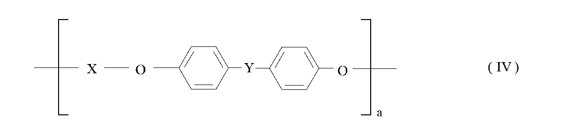
- the structure of SPAE obtained by direct copolymerization is based on the repeating structure of a hydrophobic segment represented by the following formula (IV) in which benzene rings are connected by an ether bond and a hydrophilic segment represented by the following formula (V).
- a polymer having a basic skeleton is preferable because it exhibits a rigid molecular skeleton and excellent chemical durability. Furthermore, in the basic skeletons of the following formulas (IV) and (V), particularly when X, Y, Z, and W are selected from the following combinations, the entire molecular structure becomes more rigid and has a high glass transition temperature. This is preferable because a polymer having the above can be obtained and good chemical durability can be maintained.
- a and b each represent a natural number of 1 or more
- R 1 and R 2 represent —SO 3 M or —SO 3 H
- M represents a metal element
- the sulfonation rate expressed as a percentage ratio of the number of repetitions of the formula (V) to the total number of repetitions of the formula (IV) and the formula (V) in the sulfonated polyarylene ether copolymer is 5%. Greater than and less than 80%.
- the preferred ion exchange capacity IEC ie, milliequivalents of sulfonic acid groups per gram of sulfonated polymer
- IEC milliequivalents of sulfonic acid groups per gram of sulfonated polymer
- the preferred range of sulfonation rate DS is greater than 5% and less than 80%.
- the glass transition temperature T g of the dry state of the rigidity of the indicator of SPAE molecular polymer when in accordance with the method of measuring differential scanning calorimetry to be described later (Differential Scanning Calorimetry), at 0.99 ° C. or higher 450 ° C. or less Preferably there is.
- the glass transition temperature is higher than the above range, that is, when the stiffness of the SPAE molecule is too large, the solvent solubility is lowered, the solvent does not dissolve in the solvent group 1, and there is no choice of a solvent that is substantially soluble. Therefore, it is not preferable.
- a more preferable IEC range is 0.7 to 2.9 meq.
- the range of the sulfonation rate DS is more preferably 10% to 70%, and the more preferable glass transition temperature Tg is 200 ° C. or higher and 400 ° C. or lower.
- the SPAE used in the separation layer of the present invention more preferably comprises a repeating structure of a hydrophobic segment represented by the following formula (I) and a hydrophilic segment represented by the following formula (II).
- m and n each represent a natural number of 1 or more
- R 1 and R 2 represent —SO 3 M or —SO 3 H
- M represents a metal element
- a sulfonated polyarylene ether copolymer The sulfonation rate expressed as a percentage ratio of the number of repetitions of formula (II) to the sum of the number of repetitions of formula (I) and formula (II) is greater than 5% and less than 80% .
- R 1 and R 2 in the formulas (II) and (V) represent —SO 3 H or —SO 3 M, but the metal element M in the latter case is not particularly limited, and potassium, sodium, magnesium, aluminum Cesium and the like are preferable. More preferred are potassium and sodium.
- the number average molecular weight of SPAE represented by the above formulas (I), (II), (IV) and (V) makes the coating solution suitable for viscosity, and a thin film having sufficient separation characteristics and mechanical strength as a separation layer. From the viewpoint of formation, it is preferably 1,000 to 1,000,000.
- the SPAEs represented by the above formulas (I), (II), (IV), and (V) have high mechanical strength and can form a film that has high mechanical strength and is difficult to swell. It is excellent as a composite separation membrane. Furthermore, in the SPAEs represented by the formulas (I) and (II), the hydrophobic segment of the formula (I) contains a benzonitrile structure, so that it has excellent chemical durability and has a hydrophobic portion. Since the cohesive force is increased, a film structure in which a hydrophilic domain is supported on a strong hydrophobic matrix is formed, and as a result, swelling of the separation layer is suppressed.
- Examples of the coating solvent for SPAE include dimethyl sulfoxide, N, N-dimethylacetamide, N, N-dimethylformamide, N-methyl-2-pyrrolidone, and ⁇ -butyrolactone, which are aprotic solvents of solvent group 1.
- a solvent containing at least one component is preferred.
- dimethyl sulfoxide and ⁇ -butyrolactone are more preferable because the polyphenylene ether porous support membrane is not attacked even at a high temperature.
- a solvent obtained by mixing dimethyl sulfoxide or ⁇ -butyrolactone with any of N, N-dimethylacetamide, N, N-dimethylformamide, and N-methyl-2-pyrrolidone can also be preferably used. Furthermore, by adding a solvent having a poorer solubility or a solvent having a different vapor pressure to the solvent of the solvent group 1, the evaporation rate of the coating solution is changed, and / or the solution stability is changed, whereby the composite separation is performed.
- the structure of the separation layer in the membrane may be controlled.
- the solvent of the solvent group 2 may be contained in the solvent of the solvent group 1.
- a known hydrophilic polymer such as polyethylene glycol or polyvinyl pyrrolidone may be added to change the viscosity and hydrophilicity of the SPAE coating solution.
- a known hydrophilic polymer such as polyethylene glycol or polyvinyl pyrrolidone may be added to change the viscosity and hydrophilicity of the SPAE coating solution.
- the use of these additives allows the coating solution to be applied to the surface of the porous support membrane by an appropriate amount in the coating process and / or the membrane structure of the composite separation membrane is controlled. It should be done as a normal range of devices to optimize performance.
- the concentration of SPAE in the coating solution is not particularly limited, and should be appropriately adjusted in order to control the thickness of the separation layer in the composite separation membrane.
- the final thickness of the separation layer is affected by the speed at which the coating liquid is applied to the surface of the porous support membrane, the temperature, and the like.
- the concentration of SPAE is preferably 0.01 to 20% by mass. More preferably, it is 0.1 to 10% by mass. When the concentration of SPAE is too small, the separation layer is too thin, and defects are likely to occur. On the other hand, if it is larger than this range, the separation layer is too thick and the filtration resistance increases, so that sufficient water permeability as a composite separation membrane cannot be obtained.
- the final SPAE separation layer preferably has a thickness of 30 nm to 1 ⁇ m, more preferably 50 nm to 500 nm.
- the method for applying the coating solution to the surface of the porous support membrane is not particularly limited, and known means are used.
- a method in which the coating solution is applied by hand to the surface of the porous support membrane by hand is preferable.
- a method in which a coating solution is applied to the surface of a continuously supported porous support membrane by a slide bead coater is preferably used.
- a dip coating method in which a continuously conveyed hollow fiber membrane is immersed in a bath filled with a coating solution and then pulled up and applied to the outer surface of the hollow fiber membrane.
- a dip coating method in which a continuously conveyed hollow fiber membrane is immersed in a bath filled with a coating solution and then pulled up and applied to the outer surface of the hollow fiber membrane.
- the coating solution after inserting the coating solution into the hollow fiber membrane from the cross-section of the module in which the hollow fiber membranes are bundled, either extrude the coating solution with a gas, or pull it out from one side of the module in a vacuum, so that the hollow fiber A method of coating the inner surface of the film is also preferably used.
- the coated coating solution is dried on the surface of the porous support membrane to form a SPAE thin film.
- the drying method is not particularly limited. For example, a method in which drying is performed by passing a porous support membrane coated in a forced convection drying furnace for a certain period of time is used. Or heat drying by infrared rays may be performed.
- the drying temperature, the drying time, or the ventilation speed in the forced convection oven are conditions that should be adjusted as appropriate in order to bring the composite separation membrane performance to a specific desired value. It is only necessary to appropriately adjust so that a composite separation membrane having excellent separability can be obtained without the porous support membrane being attacked by an excessively high temperature.
- the nanofiltration membrane preferably has a NaCl removal rate of about 10 to 90%.
- the water permeability is preferably as high as possible in the range in which the pressure resistance and performance stability of the separation membrane are ensured.
- the NaCl removal rate is more preferably about 20 to 85%.
- the water permeability is preferably as high as possible as long as the pressure resistance of the separation membrane and the stability of the salt removal performance are ensured.
- the composite separation membrane of the present invention is extremely suitable as a liquid treatment membrane for nanofiltration because it can satisfy the above NaCl removal rate and water permeability conditions for a long period of time.
- Example 1 (Preparation of porous support membrane)
- PPE polyphenylene ether PX100L
- NMP N-methyl-2-pyrrolidone
- a 70% NMP aqueous solution is simultaneously extruded as an internal solution while being extruded from a double cylindrical tube nozzle into a hollow shape, and is allowed to run in air at room temperature.
- the substrate was immersed in a coagulation bath at 40 ° C. filled with 35% NMP aqueous solution to produce a PPE porous support membrane, and then washed with water.
- the PPE porous support membrane washed with water was impregnated with a 50% by mass glycerin aqueous solution and then dried overnight at 50 ° C. to obtain a plugged membrane.
- the obtained PPE porous support membrane had an outer diameter of 260 ⁇ m and a thickness of 45 ⁇ m.
- the pure water permeation amount FR was 5000 L / m 2 / day at a test pressure of 0.5 MPa.
- a SPAE having a repeating structure of the hydrophobic segment represented by the above formula (I) and the hydrophilic segment represented by the formula (II) was prepared as follows.
- S-DCDPS 3,3'-disulfo-4,4'-dichlorodiphenylsulfone disodium salt
- DCBN 2,6-dichlorobenzonitrile
- 4'-biphenol 4,4'-biphenol , Potassium carbonate, and molecular sieves
- T g 322 ° C.
- the resulting SPAE polymer was examined for solubility in 2-methoxyethanol, formic acid, and diethylene glycol as solvents of solvent group 2, but sufficient solubility was not obtained. It was dissolved in all of NMP, DMAc, GBL, DMF, and DMSO in solvent group 1.
- DMSO solvent was added to the obtained SPAE and dissolved while stirring at room temperature to obtain a coating solution having a concentration of 3% by mass.
- the obtained composite separation membrane was immersed in a 50% ethanol aqueous solution for 30 minutes to perform a hydrophilic treatment, and then a performance evaluation test was performed. Under the conditions of a test pressure of 0.5 MPa and a sodium chloride concentration of 1500 mg / L, the water permeability was 510 L / m 2 / day and the salt removal rate was 48.5%.
- the thickness of the SPAE separation layer in the obtained composite separation membrane was 160 nm.
- 3 to 5 show the SEM image of the membrane cross section of the obtained composite separation membrane, the enlarged SEM image of the outer layer portion of the membrane cross section, and the enlarged SEM image of the membrane surface, respectively.
- Example 2 (Preparation of porous support membrane)
- a PPE porous support membrane was prepared in the same manner as in Example 1 and subjected to clogging treatment.
- the outer diameter of the hollow fiber membrane was 260 ⁇ m
- the film thickness was 45 ⁇ m
- the pure water permeation amount FR was 5000 L / m 2 / day at a test pressure of 0.5 MPa.
- T g 244 ° C.
- the resulting SPAE polymer was examined for solubility in 2-methoxyethanol, formic acid, and diethylene glycol as solvents of solvent group 2, but no solubility was obtained. It was dissolved in all of NMP, DMAc, GBL, DMF, and DMSO in solvent group 1.
- a composite separation membrane was obtained in the same manner as in Example 1.
- the water permeability was 40 L / m 2 / day and the salt removal rate was 84.0% under the conditions of a test pressure of 0.5 MPa and a sodium chloride concentration of 1500 mg / L.
- the thickness of the SPAE separation layer in the obtained composite separation membrane was 100 nm.
- Example 3 (Preparation of porous support membrane)
- a PPE porous support membrane was prepared in the same manner as in Example 1 and subjected to clogging treatment.
- the outer diameter of the hollow fiber membrane was 260 ⁇ m
- the film thickness was 45 ⁇ m
- the pure water permeation amount FR was 4900 L / m 2 / day at a test pressure of 0.5 MPa.
- T g 319 ° C.
- the resulting SPAE polymer was examined for solubility in 2-methoxyethanol, formic acid, and diethylene glycol as solvents of solvent group 2, but no solubility was obtained. It was dissolved in all of NMP, DMAc, GBL, DMF, and DMSO in solvent group 1.
- a composite separation membrane was obtained in the same manner as in Example 1.
- the water permeability was 102 L / m 2 / day and the salt removal rate was 81.3% under the conditions of a test pressure of 0.5 MPa and a sodium chloride concentration of 1500 mg / L.
- the thickness of the SPAE separation layer in the obtained composite separation membrane was 120 nm.
- Example 4 (Preparation of porous support membrane)
- a PPE porous support membrane was prepared in the same manner as in Example 1 and subjected to clogging treatment.
- the outer diameter of the hollow fiber membrane was 260 ⁇ m
- the film thickness was 45 ⁇ m
- the pure water permeation amount FR was 4900 L / m 2 / day at a test pressure of 0.5 MPa.
- T g 397 °C.
- the resulting SPAE polymer was examined for solubility in 2-methoxyethanol, formic acid, and diethylene glycol as solvents of solvent group 2, but sufficient solubility was not obtained. It was dissolved in all of NMP, DMAc, GBL, DMF, and DMSO in solvent group 1.
- a composite separation membrane was obtained in the same manner as in Example 1.
- the water permeability was 1600 L / m 2 / day and the salt removal rate was 20.2% under the conditions of a test pressure of 0.5 MPa and a sodium chloride concentration of 1500 mg / L.
- the thickness of the SPAE separation layer in the obtained composite separation membrane was 140 nm.
- Example 5 (Preparation of porous support membrane)
- a PPE porous support membrane was prepared in the same manner as in Example 1 and subjected to clogging treatment.
- the outer diameter of the hollow fiber membrane was 260 ⁇ m
- the film thickness was 45 ⁇ m
- the pure water permeation amount FR was 5000 L / m 2 / day at a test pressure of 0.5 MPa.
- SPAE having a repeating structure of a hydrophobic segment represented by the following formula (VI) and a hydrophilic segment represented by the formula (VII) selected from the combinations of the above formulas (IV) and (V): Prepared as follows.
- S-DCDPS 3,3′-disulfo-4,4′-dichlorodiphenylsulfone disodium salt
- DCDPS 4,4′-dichlorodiphenylsulfone
- B-biphenol 4,4′-biphenol
- Potassium carbonate 4,4′-biphenol
- molecular sieves were weighed into a four neck flask and flushed with nitrogen. After adding NMP and stirring at 150 ° C. for 50 minutes, the reaction temperature was raised to 195 ° C. to 200 ° C., and the reaction was continued with the aim of sufficiently increasing the viscosity of the system.
- T g 265 °C.
- solvent group 2 As a solvent of solvent group 2 with respect to the SPAE polymer, it did not show sufficient solubility in 2-methoxyethanol and formic acid. Diethylene glycol was slightly soluble by stirring overnight at about 130 ° C., but since the solution was gel-like at room temperature, it could not be applied satisfactorily.
- the solvent group 1 showed good solubility in NMP, DMAc, GBL, DMF and DMSO.
- Example 2 The preparation of the coating solution and the coating method were the same as in Example 1 to obtain a composite separation membrane.
- the water permeability was 44 L / m 2 / day and the salt removal rate was 82.2% under the conditions of a test pressure of 0.5 MPa and a sodium chloride concentration of 1500 mg / L.
- the thickness of the SPAE separation layer in the obtained composite separation membrane was 120 nm.
- Example 6 (Preparation of porous support membrane)
- a PPE porous support membrane was prepared in the same manner as in Example 1 and subjected to clogging treatment.
- the outer diameter of the hollow fiber membrane was 260 ⁇ m
- the film thickness was 45 ⁇ m
- the pure water permeation amount FR was 4900 L / m 2 / day at a test pressure of 0.5 MPa.
- T g 322 ° C.
- the resulting SPAE polymer was examined for solubility in 2-methoxyethanol, formic acid, and diethylene glycol as solvents of solvent group 2, but no solubility was obtained. It was dissolved in all of NMP, DMAc, GBL, DMF, and DMSO in solvent group 1.
- DMAc solvent was added to the obtained SPAE and dissolved while stirring at room temperature to obtain a coating solution having a concentration of 3% by mass.
- the obtained composite separation membrane was immersed in a 50% ethanol aqueous solution for 30 minutes to perform a hydrophilic treatment, and then a performance evaluation test was performed. Under the conditions of a test pressure of 0.5 MPa and a sodium chloride concentration of 1500 mg / L, the water permeability was 720 L / m 2 / day and the salt removal rate was 32.5%.
- the thickness of the SPAE separation layer in the obtained composite separation membrane was 160 nm.
- Example 7 (Preparation of porous support membrane)
- a PPE porous support membrane was prepared in the same manner as in Example 1 and subjected to clogging treatment.
- the outer diameter of the hollow fiber membrane was 260 ⁇ m
- the film thickness was 45 ⁇ m
- the pure water permeation amount FR was 5000 L / m 2 / day at a test pressure of 0.5 MPa.
- T g 322 ° C.
- the resulting SPAE polymer was examined for solubility in 2-methoxyethanol, formic acid, and diethylene glycol as solvents of solvent group 2, but no solubility was obtained. It was dissolved in all of NMP, DMAc, GBL, DMF, and DMSO in solvent group 1.
- NMP solvent was added to the obtained SPAE and dissolved while stirring at room temperature to obtain a coating solution having a concentration of 3% by mass.
- the obtained composite separation membrane was immersed in a 50% ethanol aqueous solution for 30 minutes to perform a hydrophilic treatment, and then a performance evaluation test was performed. Under conditions of a test pressure of 0.5 MPa and a sodium chloride concentration of 1500 mg / L, the water permeability was 780 L / m 2 / day, and the salt removal rate was 33.0%.
- the thickness of the SPAE separation layer in the obtained composite separation membrane was 190 nm.
- Example 8> (Preparation of porous support membrane)
- a PPE porous support membrane was prepared in the same manner as in Example 1 and subjected to clogging treatment.
- the outer diameter of the hollow fiber membrane was 260 ⁇ m
- the film thickness was 45 ⁇ m
- the pure water permeation amount FR was 5000 L / m 2 / day at a test pressure of 0.5 MPa.
- T g 322 ° C.
- the resulting SPAE polymer was examined for solubility in 2-methoxyethanol, formic acid, and diethylene glycol as solvents of solvent group 2, but no solubility was obtained. It was dissolved in all of NMP, DMAc, GBL, DMF, and DMSO in solvent group 1.
- DMF solvent was added to the obtained SPAE and dissolved while stirring at room temperature to obtain a coating solution having a concentration of 3% by mass.
- the obtained composite separation membrane was immersed in a 50% ethanol aqueous solution for 30 minutes to perform a hydrophilic treatment, and then a performance evaluation test was performed. Under conditions of a test pressure of 0.5 MPa and a sodium chloride concentration of 1500 mg / L, the water permeability was 460 L / m 2 / day, and the salt removal rate was 47.0%.
- the thickness of the SPAE separation layer in the obtained composite separation membrane was 170 nm.
- Example 9 (Preparation of porous support membrane)
- a PPE porous support membrane was prepared in the same manner as in Example 1 and subjected to clogging treatment.
- the outer diameter of the hollow fiber membrane was 260 ⁇ m
- the film thickness was 45 ⁇ m
- the pure water permeation amount FR was 4900 L / m 2 / day at a test pressure of 0.5 MPa.
- T g 322 ° C.
- the resulting SPAE polymer was examined for solubility in 2-methoxyethanol, formic acid, and diethylene glycol as solvents of solvent group 2, but no solubility was obtained. It was dissolved in all of NMP, DMAc, GBL, DMF, and DMSO in solvent group 1.
- GBL solvent was added to the obtained SPAE and dissolved while stirring at room temperature to obtain a coating solution having a concentration of 3% by mass.
- the obtained composite separation membrane was immersed in a 50% ethanol aqueous solution for 30 minutes to perform a hydrophilic treatment, and then a performance evaluation test was performed. Under the conditions of a test pressure of 0.5 MPa and a sodium chloride concentration of 1500 mg / L, the water permeability was 490 L / m 2 / day and the salt removal rate was 54.5%.
- the thickness of the SPAE separation layer in the obtained composite separation membrane was 120 nm.
- Example 10 (Preparation of porous support membrane)
- a PPE porous support membrane was prepared in the same manner as in Example 1 and subjected to clogging treatment.
- the outer diameter of the hollow fiber membrane was 260 ⁇ m
- the film thickness was 45 ⁇ m
- the pure water permeation amount FR was 4900 L / m 2 / day at a test pressure of 0.5 MPa.
- T g 322 ° C.
- the resulting SPAE polymer was examined for solubility in 2-methoxyethanol, formic acid, and diethylene glycol as solvents of solvent group 2, but no solubility was obtained. It was dissolved in all of NMP, DMAc, GBL, DMF, and DMSO in solvent group 1.
- a mixed solvent of NMP and DMSO having a weight ratio of 50:50 was added to the obtained SPAE and dissolved while stirring at room temperature to obtain a coating solution having a concentration of 3 mass percent.
- the obtained composite separation membrane was immersed in a 50% ethanol aqueous solution for 30 minutes to perform a hydrophilic treatment, and then a performance evaluation test was performed. Under conditions of a test pressure of 0.5 MPa and a sodium chloride concentration of 1500 mg / L, the water permeability was 445 L / m 2 / day, and the salt removal rate was 58.2%.
- the thickness of the SPAE separation layer in the obtained composite separation membrane was 100 nm.
- Example 11 (Preparation of porous support membrane)
- a PPE porous support membrane was prepared in the same manner as in Example 1 and subjected to clogging treatment.
- the outer diameter of the hollow fiber membrane was 260 ⁇ m
- the film thickness was 45 ⁇ m
- the pure water permeation amount FR was 5200 L / m 2 / day at a test pressure of 0.5 MPa.
- T g 322 ° C.
- the resulting SPAE polymer was examined for solubility in 2-methoxyethanol, formic acid, and diethylene glycol as solvents of solvent group 2, but no solubility was obtained. It was dissolved in all of NMP, DMAc, GBL, DMF, and DMSO in solvent group 1.
- a mixed solvent having a weight ratio of NMP and diethylene glycol of 50:50 was added to the obtained SPAE and dissolved while stirring at room temperature to obtain a coating solution having a concentration of 3% by mass.
- the obtained composite separation membrane was immersed in a 50% ethanol aqueous solution for 30 minutes to perform a hydrophilic treatment, and then a performance evaluation test was performed. Under conditions of a test pressure of 0.5 MPa and a sodium chloride concentration of 1500 mg / L, the water permeability was 382 L / m 2 / day, and the salt removal rate was 54.2%.
- the thickness of the SPAE separation layer in the obtained composite separation membrane was 220 nm.
- Example 12 (Preparation of porous support membrane)
- polyphenylene ether PX100L (hereinafter abbreviated as PPE) manufactured by Mitsubishi Engineering Plastics Co., Ltd. was prepared in the same manner as in Example 1.
- NMP N-methyl-2-pyrrolidone
- a polyester paper (05TH-60 made by Hirose Paper), which was appropriately impregnated with a 50% glycerin aqueous solution, was placed. It was applied with a hand coater. After drying for about 10 seconds, the film was immersed in a coagulation bath of 35% NMP aqueous solution at 30 ° C. to obtain a flat membrane-like porous support membrane. Then, the water washing process was performed. The thickness of the PPE porous support membrane excluding the polyester papermaking portion of the obtained membrane was 40 ⁇ m.
- the PPE porous support membrane washed with water was impregnated with a 50% by mass glycerin aqueous solution and then dried overnight at 50 ° C. to obtain a plugged membrane.
- T g 244 ° C.
- the resulting SPAE polymer was examined for solubility in 2-methoxyethanol, formic acid, and diethylene glycol as solvents of solvent group 2, but no solubility was obtained. It was dissolved in all of NMP, DMAc, GBL, DMF, and DMSO in solvent group 1.
- DMSO solvent was added to the obtained SPAE and dissolved while stirring at room temperature to obtain a 0.7 mass% coating solution and a 0.1 mass% coating solution.
- the composite membrane was formed by brushing on the surface of a 30 cm square flat PPE porous support membrane. Since it was confirmed that the brush coating tends to cause defects due to coating unevenness, the above 0.7 mass% coating solution was carefully applied and dried with gentle hot air at 80 ° C. for 30 minutes. Thereafter, the coating solution of 0.1% by mass was brushed again from above, and the defect was reduced by re-drying at 80 ° C. for 30 minutes.
- the obtained composite separation membrane was immersed in a 50% ethanol aqueous solution for 30 minutes to perform a hydrophilic treatment, and then a performance evaluation test was performed. Except for using a flat membrane evaluation device, the same as in the other examples, when using the evaluation conditions of a test pressure of 0.5 MPa and a sodium chloride concentration of 1500 mg / L, the water permeability was 43 L / m 2 / day, The salt removal rate was 84.0%.
- the thickness of the SPAE separation layer in the obtained composite separation membrane was 350 nm.
- a 70% NMP aqueous solution is simultaneously extruded as an internal solution while being extruded from a double cylindrical tube nozzle into a hollow fiber membrane shape.
- the PES porous support membrane was prepared by immersing in a coagulation bath at 40 ° C. filled with 35% NMP aqueous solution, and then washed with water.
- the PES porous support membrane washed with water was impregnated with a 50% by mass glycerin aqueous solution and then dried overnight at 50 ° C. to obtain a plugged membrane.
- the obtained PES porous support membrane had an outer diameter of 255 ⁇ m and a thickness of 40 ⁇ m.
- the pure water permeation amount FR was 3800 L / m 2 / day at a test pressure of 0.5 MPa.
- PVDF Polyvinylidene fluoride kynar 301F
- PVP polyvinylpyrrolidone K85
- a 70% NMP aqueous solution is simultaneously extruded as an inner liquid while being extruded from a double cylindrical tube nozzle into a hollow fiber membrane shape.
- the substrate was immersed in a coagulation bath at 40 ° C. filled with 35% NMP aqueous solution to produce a PVDF porous support membrane, and then washed with water.
- the PVDF porous support membrane washed with water was impregnated with a 50% by mass glycerin aqueous solution and then dried at 50 ° C. overnight to obtain a plugged membrane.
- the obtained PVDF porous support membrane had an outer diameter of 260 ⁇ m and a thickness of 50 ⁇ m.
- the pure water permeation amount FR was 2400 L / m 2 / day at a test pressure of 0.5 MPa.
- the glass transition temperature of the dried SPAE polymer powder was evaluated by Differential Scanning Calorimetry (DSC).
- the polymer sample was filled in an aluminum sample pan and measured using a TA instrument Q100.
- As the first scan the glass transition temperature was evaluated by a second scan in which the temperature was increased to a temperature at which SPAE was not thermally decomposed, cooled, and then heated again. Since the data of moisture contained in the polymer is mixed in the first scan, the second scan is adopted to exclude the influence of water on the data. Specifically, the temperature was raised from 20 ° C. to 320 ° C. at 20 ° C./min, and the temperature was lowered to 20 ° C. at 20 ° C./min.
- the temperature was raised again from 20 ° C. to 450 ° C. at 20 ° C./min.
- the glass transition temperature was evaluated by using Universal Analysis 2000 manufactured by TA instruments to evaluate the center point of the heat capacity change step.
- the temperature reached in the first scan should be kept to a level that does not significantly degrade the polymer, if necessary.
- Thermogravimetric analysis thermogravimetric method (Analysis, TGA) to investigate the polymer decomposition temperature and adjust the temperature reached in the first scan.
- the temperature should be less than the temperature at which a 5% weight loss of the polymer occurs under an inert gas atmosphere.
- porous support membrane shape The shape evaluation of the porous support membrane samples (hollow fibers) of Examples 1 to 11 was performed by the following method. An appropriate amount of a hollow fiber bundle is packed into a hole of a 2 mm thick SUS plate with a 3 mm ⁇ hole, cut with a razor blade to expose a cross section, and then a Nikon microscope (ECLIPSE LV100) and Nikon image processing The cross-sectional shape was photographed using a device (DIGITAL SIGN DS-U2) and a CCD camera (DS-Ri1), and the outer diameter and inner diameter of the hollow fiber membrane cross section were measured using image analysis software (NIS Element D3.00 SP6).
- a device DIGITAL SIGN DS-U2
- DS-Ri1 CCD camera
- the outer diameter, inner diameter, and thickness of the hollow fiber membrane were calculated by measuring using the measurement function of the analysis software.
- the shape of the porous support membrane sample (flat membrane) of Example 12 was evaluated by freezing the water-containing sample with liquid nitrogen, cleaving, air drying, and sputtering Pt on the fractured surface. Using a scanning electron microscope S-4800 manufactured by Seisakusho, observation was made at an acceleration voltage of 5 kV, and the thickness of the porous support film excluding the polyester nonwoven fabric portion was measured.
- FIG. 1 shows an SEM image of the composite separation membrane of Example 1 as an example of the SEM image. The thickness of the separation layer was measured by photographing the outer layer portion of the membrane.
- the hollow fiber membranes of Examples 1 to 11 were bundled and inserted into a plastic sleeve, and then a thermosetting resin was injected into the sleeve, cured and sealed. An end face of the hollow fiber membrane cured with the thermosetting resin was cut to obtain an opening surface of the hollow fiber membrane, and an evaluation module was produced. This evaluation module was connected to a hollow fiber membrane performance testing device consisting of a feed water tank and a pump to evaluate the performance.
- the flat membrane of Example 12 was installed in a flat membrane performance evaluation apparatus comprising a supply water tank and a pump in the same manner as described above, and the performance was evaluated.
- the sodium chloride concentration was measured using the electric conductivity meter (Toa DKK Corporation CM-25R) for the membrane permeated water collected in the water permeability measurement and the sodium chloride concentration 1500 mg / L aqueous solution used in the same water permeability measurement. .
- the composite separation membrane of the present invention is extremely useful for nanofiltration treatment and reverse osmosis treatment because salt removal and water permeability can be maintained at a high level for a long time while using a material excellent in chemical resistance.
Landscapes
- Chemical & Material Sciences (AREA)
- Chemical Kinetics & Catalysis (AREA)
- Engineering & Computer Science (AREA)
- Water Supply & Treatment (AREA)
- Manufacturing & Machinery (AREA)
- Hydrology & Water Resources (AREA)
- Life Sciences & Earth Sciences (AREA)
- Environmental & Geological Engineering (AREA)
- Organic Chemistry (AREA)
- Nanotechnology (AREA)
- Inorganic Chemistry (AREA)
- Separation Using Semi-Permeable Membranes (AREA)
- Manufacture Of Porous Articles, And Recovery And Treatment Of Waste Products (AREA)
Description


(1)多孔性支持膜の表面に分離層を有する複合分離膜であって、前記多孔性支持膜がポリフェニレンエーテルを50質量%以上含み、前記分離層が、疎水性セグメントと、親水性セグメントの繰り返し構造からなるスルホン化ポリアリーレンエーテル共重合体からなることを特徴とする複合分離膜。
(2)前記スルホン化ポリアリーレンエーテル共重合体は、下記式(IV)で表される疎水性セグメントと、下記式(V)で表される親水性セグメントの繰り返し構造からなることを特徴とする(1)に記載の複合分離膜:


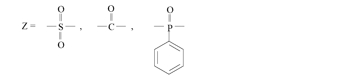
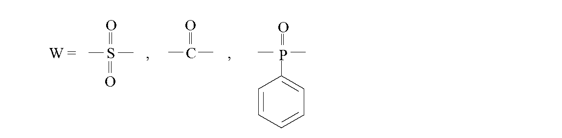
YとWは同じものが選択されることはなく、
aおよびbはそれぞれ1以上の自然数を表し、
R1およびR2は、-SO3Mあるいは-SO3Hを表し、Mは金属元素を表し、
スルホン化ポリアリーレンエーテル共重合体中の式(IV)の繰り返し数と式(V)の繰り返し数の合計に対する式(V)の繰り返し数の百分率割合として表されるスルホン化率が、5%よりも大きく、80%よりも小さい。
(3)前記スルホン化ポリアリーレンエーテル共重合体は、下記式(I)で表される疎水性セグメントと、下記式(II)で表される親水性セグメントの繰り返し構造からなることを特徴とする(1)に記載の複合分離膜:


(4)多孔性支持膜中のポリフェニレンエーテルの含有割合が80質量%以上であることを特徴とする(1)~(3)のいずれかに記載の複合分離膜。
(5)ジメチルスルホキシド、N,N-ジメチルアセトアミド、N,N-ジメチルホルムアミド、N-メチル-2-ピロリドン、およびγ-ブチロラクトンから選択される少なくとも1種を含む非プロトン性極性溶媒に、スルホン化ポリアリーレンエーテル共重合体を溶解して得られるコーティング溶液を、ポリフェニレンエーテルを50質量%以上含む多孔性支持膜の表面に塗布した後、前記溶媒がポリフェニレンエーテル多孔性支持膜を溶解しない温度範囲において、塗布表面を乾燥処理することを特徴とする(1)~(4)のいずれかに記載の複合分離膜の製造方法。


YとWは同じものが選択されることはなく、
aおよびbはそれぞれ1以上の自然数を表し、
R1およびR2は、-SO3Mあるいは-SO3Hを表し、Mは金属元素を表し、
スルホン化ポリアリーレーンエーテル共重合体中の式(IV)の繰り返し数と式(V)の繰り返し数の合計に対する式(V)の繰り返し数の百分率割合として表されるスルホン化率が、5%よりも大きく、80%よりも小さい。


(多孔性支持膜の作製)
多孔性支持膜のポリマーとして、三菱エンジニアリングプラスチックス株式会社製のポリフェニレンエーテルPX100L(以下、PPEと略す。)を準備した。PPEが30質量パーセントとなるように、N-メチル-2-ピロリドン(以下、NMPと略す。)を加えて混練しながら、130℃で溶解させて、均一な製膜原液を得た。
上記の式(I)で表される疎水性セグメントと式(II)で表される親水性セグメントの繰り返し構造を有するSPAEを以下のようにして準備した。
(多孔性支持膜の作製)
多孔性支持膜のポリマーとして、実施例1と同じ方法でPPE多孔性支持膜を作製し、目詰め処理を施した。中空糸膜の外径は260μm、膜厚は45μmであり、純水透過量FRは0.5MPaの試験圧力において、5000L/m2/日であった。
S-DCDPSおよびDCBNの仕込み量比を変更したこと以外は、実施例1と同様の方法でDS=15%のSPAEを得た。
(多孔性支持膜の作製)
多孔性支持膜のポリマーとして、実施例1と同じ方法でPPE多孔性支持膜を作製し、目詰め処理を施した。中空糸膜の外径は260μm、膜厚は45μmであり、純水透過量FRは0.5MPaの試験圧力において、4900L/m2/日であった。
S-DCDPSおよびDCBNの仕込み量比を変更したこと以外は、実施例1と同様の方法でDS=26.5%のSPAEを得た。
(多孔性支持膜の作製)
多孔性支持膜のポリマーとして、実施例1と同じ方法でPPE多孔性支持膜を作製し、目詰め処理を施した。中空糸膜の外径は260μm、膜厚は45μmであり、純水透過量FRは0.5MPaの試験圧力において、4900L/m2/日であった。
S-DCDPSおよびDCBNの仕込み量比を変更したこと以外は、実施例1と同様の方法でDS=65%のSPAEを得た。
(多孔性支持膜の作製)
多孔性支持膜のポリマーとして、実施例1と同じ方法でPPE多孔性支持膜を作製し、目詰め処理を施した。中空糸膜の外径は260μm、膜厚は45μmであり、純水透過量FRは0.5MPaの試験圧力において、5000L/m2/日であった。
前記式(IV)、(V)の組合せのなかから選択し、下記の式(VI)で表される疎水性セグメントと式(VII)で表される親水性セグメントの繰り返し構造を有するSPAEを以下のようにして準備した。
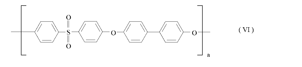

(多孔性支持膜の作製)
多孔性支持膜のポリマーとして、実施例1と同じ方法でPPE多孔性支持膜を作製し、目詰め処理を施した。中空糸膜の外径は260μm、膜厚は45μmであり、純水透過量FRは0.5MPaの試験圧力において、4900L/m2/日であった。
実施例1と同様な方法でDS=44%のSPAEを得た。
(多孔性支持膜の作製)
多孔性支持膜のポリマーとして、実施例1と同じ方法でPPE多孔性支持膜を作製し、目詰め処理を施した。中空糸膜の外径は260μm、膜厚は45μmであり、純水透過量FRは0.5MPaの試験圧力において、5000L/m2/日であった。
実施例1と同様な方法でDS=44%のSPAEを得た。
(多孔性支持膜の作製)
多孔性支持膜のポリマーとして、実施例1と同じ方法でPPE多孔性支持膜を作製し、目詰め処理を施した。中空糸膜の外径は260μm、膜厚は45μmであり、純水透過量FRは0.5MPaの試験圧力において、5000L/m2/日であった。
実施例1と同様な方法でDS=44%のSPAEを得た。
(多孔性支持膜の作製)
多孔性支持膜のポリマーとして、実施例1と同じ方法でPPE多孔性支持膜を作製し、目詰め処理を施した。中空糸膜の外径は260μm、膜厚は45μmであり、純水透過量FRは0.5MPaの試験圧力において、4900L/m2/日であった。
実施例1と同様な方法でDS=44%のSPAEを得た。
(多孔性支持膜の作製)
多孔性支持膜のポリマーとして、実施例1と同じ方法でPPE多孔性支持膜を作製し、目詰め処理を施した。中空糸膜の外径は260μm、膜厚は45μmであり、純水透過量FRは0.5MPaの試験圧力において、4900L/m2/日であった。
実施例1と同様な方法でDS=44%のSPAEを得た。
(多孔性支持膜の作製)
多孔性支持膜のポリマーとして、実施例1と同じ方法でPPE多孔性支持膜を作製し、目詰め処理を施した。中空糸膜の外径は260μm、膜厚は45μmであり、純水透過量FRは0.5MPaの試験圧力において、5200L/m2/日であった。
実施例1と同様な方法でDS=44%のSPAEを得た。
(多孔性支持膜の作製)
多孔性支持膜のポリマーとして、実施例1と同様に、三菱エンジニアリングプラスチックス株式会社製のポリフェニレンエーテルPX100L(以下、PPEと略す。)を準備した。PPEが18質量パーセントとなるように、N-メチル-2-ピロリドン(以下、NMPと略す。)を加えて混練しながら、130℃で溶解させて、均一な製膜原液を得た。
実施例2と同様な方法でDS=15%のSPAEを得た。
(多孔性支持膜の作製)
多孔性支持膜のポリマーとして、住友化学株式会社製のポリエーテルスルホン5200P(以下、PESと略す。)を、また親水性ポリマーとしてBASF社製ポリビニルピロリドンK85(以下PVPと略す)を準備した。PESが30質量%、PVPが2質量%となるように、NMPを加えて混練しながら、120℃で溶解させて、均一な製膜原液を得た。
実施例1と同一の方法で得られたDMSO溶媒のSPAEコーティング液で満たした浴槽にPES多孔性支持膜を通糸したところ、著しく膜が膨潤した後、溶解して糸切れを起こしたため、複合分離膜を得ることができなかった。
(多孔性支持膜の作製)
多孔性支持膜のポリマーとして、アルケマ株式会社製のポリフッ化ビニリデンkynar301F(以下、PVDFと略す。)を、また親水性ポリマーとしてBASF社製ポリビニルピロリドンK85(以下PVPと略す)を準備した。PVDFが28質量%、PVPが2質量%となるように、NMPを加えて混練しながら、140℃で溶解させて、均一な製膜原液を得た。
実施例1と同一の方法で得られたDMSO溶媒のSPAEコーティング液で満たした浴槽にPVDF多孔性支持膜を通糸したところ、比較例1のPES膜の場合と同様、膜の膨潤がみられ、80℃の乾燥炉の中で糸が溶解して糸切れを起こしたため、複合分離膜を得ることができなかった。
(コーティング溶液の作製)
実施例3と同じ方法で得られたスルホン化度DS=26.5%のSPAEを、3質量%となるように、溶媒群2のうち、2-メトキシエタノール、ギ酸、ジエチレングリコールをそれぞれ添加し、100℃で撹拌したが、溶解状態が得られず、複合分離膜を得ることはできなかった。
SPAEポリマーのスルホン化度、イオン交換容量(IEC)およびガラス転移温度は以下のように評価した。
窒素雰囲気下で一晩乾燥したSPAEポリマーの重量を測定し、水酸化ナトリウム水溶液と攪拌処理した後、塩酸水溶液による逆滴定を行うことでイオン交換容量(IEC)を評価した。
真空乾燥器で100℃、1晩乾燥させたポリマー20mgを、ナカライテスク社の重水素化DMSO(DMSO-d6)1mLに溶解させ、これをBRUKER AVANCE500(周波数500.13MHz、温度30℃、FT積算32回)にてプロトンNMR測定した。得られたスペクトルチャートにおいて、疎水性セグメントおよび親水性セグメントに含まれる各プロトンとピーク位置の関係を同定し、疎水性セグメントにおけるプロトンのうち独立したピークと、親水性セグメントにおけるプロトンのうち独立したピークの1個のプロトンあたりの積分強度の比から求めた。
乾燥状態のSPAEポリマー粉末のガラス転移温度を、示差走査熱量分析法(Differential Scanning Calorimetry,DSC)によって評価した。ポリマーサンプルをアルミニウム製の試料パンに充填し、TA instrument社製Q100を用いて測定した。第1スキャンとして、SPAEが熱分解しない温度まで昇温させた後、冷却し、再度昇温させた第2スキャンで、ガラス転移温度を評価した。第1スキャンにはポリマーに含まれる水分のデータが混入するので、データへの水の影響を除外するため、第2スキャンを採用する。具体的には、20℃から320℃まで、20℃/minで昇温し、20℃まで20℃/minで降温させた。その後、第2スキャンとして、再度20℃から450℃まで、20℃/minで昇温させた。ガラス転移温度は、TA instruments社製のUniversal Analysis 2000を用いて、熱容量変化ステップの中心点を評価した。ただし、SPAEの化学構造によって、ポリマーの熱安定性が変りうるため、必要に応じて、第1スキャンの到達温度はポリマーを著しく劣化させない程度に留めるべきであり、事前に熱重量分析法(Thermogravimetric Analysis,TGA)により、ポリマーの分解温度を調査して、前記の第1スキャンの到達温度を調整する。目安として不活性ガス雰囲気下にて、ポリマーの5%重量減少が起こる温度未満にする。
上記のようにして作製された実施例1~12の複合分離膜について、以下の方法で、膜形状の評価、分離層の厚み評価、分離性能および透過性能の評価を行なった。
実施例1~11の多孔性支持膜サンプル(中空糸)の形状評価は以下の方法で行った。3mmφの孔を空けた2mm厚のSUS板の孔に、適量の中空糸束を詰め、カミソリ刃でカットして断面を露出させた後、Nikon製の顕微鏡(ECLIPSE LV100)およびNikon製の画像処理装置(DIGITAL SIGHT DS-U2)およびCCDカメラ(DS-Ri1)を用いて、断面の形状を撮影し、画像解析ソフト(NIS Element D3.00 SP6)により、中空糸膜断面の外径および内径を、該解析ソフトの計測機能を用いて測定することで中空糸膜の外径および内径および厚みを算出した。実施例12の多孔性支持膜サンプル(平膜)の形状評価は、含水状態のサンプルを液体窒素で凍結させ、割断し、風乾させて、その割断面にPtをスパッタリングさせて、(株)日立製作所製の走査型電子顕微鏡S-4800を用いて、加速電圧5kVで観察し、ポリエステル不織布部分を除く、多孔性支持膜の厚みを計測した。
実施例1~12の複合分離膜を50%エタノール水溶液で親水化処理した後、水に浸漬したものを液体窒素で凍結させ、割断し、風乾させて、その割断面にPtをスパッタリングさせて、(株)日立製作所製の走査型電子顕微鏡S-4800を用いて、加速電圧5kVで観察した。図1に、SEM像の一例として、実施例1の複合分離膜のSEM像を示す。分離層の厚みは膜の外層部を撮影して測定した。
実施例1~11の中空糸膜を束ねて、プラスチック製スリーブに挿入した後、熱硬化性樹脂をスリーブに注入し、硬化させ封止した。熱硬化性樹脂で硬化させた中空糸膜の端部を切断することで中空糸膜の開口面を得て、評価用モジュールを作製した。この評価用モジュールを供給水タンク、ポンプからなる中空糸膜性能試験装置に接続し、性能評価した。実施例12の平膜は、上記と同様、供給水タンク、ポンプの構成からなる平膜性能評価装置に設置し、性能評価した。評価条件は、塩化ナトリウム濃度1500mg/Lの供給水溶液を、25℃、圧力0.5MPaで約30~1時間運転させ、その後、膜からの透過水を採取して、電子天秤(島津製作所 LIBROR EB-3200D)で透過水重量を測定した。透過水重量は、下記式にて25℃の透過水量に換算した。
透過水量(L)=透過水重量(kg)/0.99704(kg/L)
透水量(FR)は下記式より算出した。
FR[L/m2/日]=透過水量[L]/膜面積[m2]/採取時間[分]×(60[分]×24[時間])
塩除去率は下記式より算出した。
塩除去率[%]=(1-膜透過水塩濃度[mg/L]/供給水溶液塩濃度[mg/L])×100

2 PPEからなる多孔性支持膜
3 不織布
Claims (5)
- 多孔性支持膜の表面に分離層を有する複合分離膜であって、前記多孔性支持膜がポリフェニレンエーテルを50質量%以上含み、前記分離層が、疎水性セグメントと、親水性セグメントの繰り返し構造からなるスルホン化ポリアリーレンエーテル共重合体からなることを特徴とする複合分離膜。
- 前記スルホン化ポリアリーレンエーテル共重合体は、下記式(IV)で表される疎水性セグメントと、下記式(V)で表される親水性セグメントの繰り返し構造からなることを特徴とする請求項1に記載の複合分離膜:
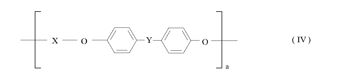 上記式中、
上記式中、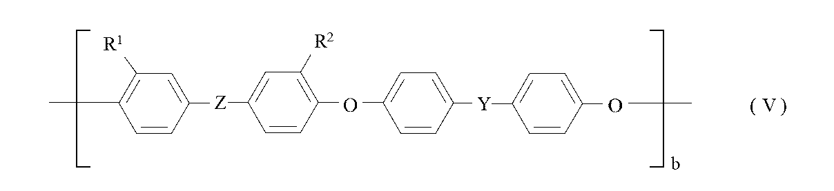
であり、
であり、
であり、
であり、
YとWは同じものが選択されることはなく、
aおよびbはそれぞれ1以上の自然数を表し、
R1およびR2は、-SO3Mあるいは-SO3Hを表し、Mは金属元素を表し、
スルホン化ポリアリーレンエーテル共重合体中の式(IV)の繰り返し数と式(V)の繰り返し数の合計に対する式(V)の繰り返し数の百分率割合として表されるスルホン化率が、5%よりも大きく、80%よりも小さい。 - 前記スルホン化ポリアリーレンエーテル共重合体は、下記式(I)で表される疎水性セグメントと、下記式(II)で表される親水性セグメントの繰り返し構造からなることを特徴とする請求項1に記載の複合分離膜:
 上記式中、mおよびnはそれぞれ1以上の自然数を表し、R1およびR2は、-SO3Mあるいは-SO3Hを表し、Mは金属元素を表し、スルホン化ポリアリーレンエーテル共重合体中の式(I)の繰り返し数と式(II)の繰り返し数の合計に対する式(II)の繰り返し数の百分率割合として表されるスルホン化率が、5%よりも大きく、80%よりも小さい。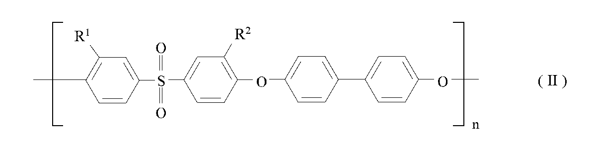
- 多孔性支持膜中のポリフェニレンエーテルの含有割合が80質量%以上であることを特徴とする請求項1~3のいずれかに記載の複合分離膜。
- ジメチルスルホキシド、N,N-ジメチルアセトアミド、N,N-ジメチルホルムアミド、N-メチル-2-ピロリドン、およびγ-ブチロラクトンから選択される少なくとも1種を含む非プロトン性極性溶媒に、スルホン化ポリアリーレンエーテル共重合体を溶解して得られるコーティング溶液を、ポリフェニレンエーテルを50質量%以上含む多孔性支持膜の表面に塗布した後、前記溶媒がポリフェニレンエーテル多孔性支持膜を溶解しない温度範囲において、塗布表面を乾燥処理することを特徴とする請求項1~4のいずれかに記載の複合分離膜の製造方法。
Priority Applications (4)
| Application Number | Priority Date | Filing Date | Title |
|---|---|---|---|
| CA2884579A CA2884579C (en) | 2012-10-04 | 2013-08-20 | Sulfonated polyarylene ether composite seperation membrane |
| JP2014513812A JP5578300B1 (ja) | 2012-10-04 | 2013-08-20 | 複合分離膜 |
| US14/419,030 US10625217B2 (en) | 2012-10-04 | 2013-08-20 | Composite separation membrane |
| BR112015006144-3A BR112015006144B1 (pt) | 2012-10-04 | 2013-08-20 | membrana compósita de separação, e método para a fabricação da membrana compósita de separação |
Applications Claiming Priority (2)
| Application Number | Priority Date | Filing Date | Title |
|---|---|---|---|
| JP2012-221891 | 2012-10-04 | ||
| JP2012221891 | 2012-10-04 |
Publications (1)
| Publication Number | Publication Date |
|---|---|
| WO2014054346A1 true WO2014054346A1 (ja) | 2014-04-10 |
Family
ID=50434679
Family Applications (1)
| Application Number | Title | Priority Date | Filing Date |
|---|---|---|---|
| PCT/JP2013/072154 Ceased WO2014054346A1 (ja) | 2012-10-04 | 2013-08-20 | 複合分離膜 |
Country Status (5)
| Country | Link |
|---|---|
| US (1) | US10625217B2 (ja) |
| JP (1) | JP5578300B1 (ja) |
| BR (1) | BR112015006144B1 (ja) |
| CA (1) | CA2884579C (ja) |
| WO (1) | WO2014054346A1 (ja) |
Cited By (4)
| Publication number | Priority date | Publication date | Assignee | Title |
|---|---|---|---|---|
| JP6094922B1 (ja) * | 2015-10-13 | 2017-03-15 | 東洋紡株式会社 | 複合分離膜 |
| JP2017514957A (ja) * | 2014-05-01 | 2017-06-08 | サビック グローバル テクノロジーズ ベスローテン フェンノートシャップ | ポリ(フェニレンエーテル)および両親媒性ポリマを含む支持体を有する複合膜、製造方法、およびその分離モジュール |
| CN109289553A (zh) * | 2018-10-26 | 2019-02-01 | 德蓝水技术股份有限公司 | 连续制备中空纤维复合膜的装置及方法 |
| WO2021049623A1 (ja) | 2019-09-13 | 2021-03-18 | 東洋紡株式会社 | 複合膜および複合膜の製造方法 |
Families Citing this family (6)
| Publication number | Priority date | Publication date | Assignee | Title |
|---|---|---|---|---|
| JP6001013B2 (ja) * | 2013-08-13 | 2016-10-05 | 富士フイルム株式会社 | 酸性ガス分離用スパイラル型モジュール |
| KR102160404B1 (ko) * | 2017-10-12 | 2020-09-28 | 가부시끼가이샤 구레하 | 폴리아릴에테르케톤의 제조 방법 |
| KR101979685B1 (ko) * | 2018-11-06 | 2019-05-17 | 한양대학교 산학협력단 | 유기용매 나노여과용 박막 복합막 및 그 제조방법 |
| JP7581642B2 (ja) * | 2020-03-30 | 2024-11-13 | 東洋紡株式会社 | ポリフェニレン系半透膜およびその製造方法 |
| JP7305712B2 (ja) * | 2021-07-15 | 2023-07-10 | 東洋紡株式会社 | 半透膜 |
| WO2025037493A1 (ja) | 2023-08-17 | 2025-02-20 | 東洋紡株式会社 | 変性ポリフェニレンオキサイド分離膜およびその製造方法 |
Citations (2)
| Publication number | Priority date | Publication date | Assignee | Title |
|---|---|---|---|---|
| JPS63248409A (ja) * | 1987-02-04 | 1988-10-14 | ハイドロノーティクス | 改良された耐酸化性膜およびその製造方法 |
| JP2007002099A (ja) * | 2005-06-23 | 2007-01-11 | Toyobo Co Ltd | 透湿材料 |
Family Cites Families (21)
| Publication number | Priority date | Publication date | Assignee | Title |
|---|---|---|---|---|
| US3648845A (en) * | 1969-09-02 | 1972-03-14 | Us Interior | Thin film separation membranes and processes for making same |
| US4073724A (en) | 1973-02-27 | 1978-02-14 | Rhone-Poulenc, S.A. | Anisotropic phenolic polyether membrane |
| US4277344A (en) | 1979-02-22 | 1981-07-07 | Filmtec Corporation | Interfacially synthesized reverse osmosis membrane |
| JPH0767529B2 (ja) * | 1985-09-30 | 1995-07-26 | 日東電工株式会社 | スルホン化ポリアリールエーテル系ポリマーからなる分離用膜 |
| JPS6295105A (ja) | 1985-10-16 | 1987-05-01 | イ−・アイ・デユポン・デ・ニモアス・アンド・カンパニ− | 複合逆浸透膜のための被覆方法 |
| JPH0628713B2 (ja) * | 1986-02-28 | 1994-04-20 | ダイセル化学工業株式会社 | 親水化ポリスルホン膜 |
| US4990252A (en) * | 1987-02-04 | 1991-02-05 | Hydanautics | Stable membranes from sulfonated polyarylethers |
| JP3250644B2 (ja) | 1995-04-12 | 2002-01-28 | 東洋紡績株式会社 | 複合中空糸膜およびその製造方法 |
| JP2005044610A (ja) * | 2003-07-28 | 2005-02-17 | Toyobo Co Ltd | 複合イオン交換膜およびその製造方法 |
| JP2005243495A (ja) * | 2004-02-27 | 2005-09-08 | Toyobo Co Ltd | イオン交換膜 |
| JP2007063533A (ja) * | 2005-08-02 | 2007-03-15 | Toyobo Co Ltd | スルホン酸基含有ポリマーとその用途および製造方法 |
| WO2007084759A2 (en) * | 2006-01-18 | 2007-07-26 | Board Of Regents, The University Of Texas System | Chlorine resistant desalination membranes based on directly sulfonated poly(arylene ether sulfone) copolymers |
| DE102006036496A1 (de) * | 2006-07-28 | 2008-02-07 | Leibniz-Institut Für Polymerforschung Dresden E.V. | Sulfonierte Polyarylverbindungen, Membranmaterial daraus, Verfahren zu ihrer Herstellung und Verwendung |
| EP2183299A1 (en) | 2007-08-20 | 2010-05-12 | Technion Research and Development Foundation, Ltd. | Polysulfone polymers and membranes for reverse osmosis, nanofiltration and ultrafiltration |
| US8574664B2 (en) * | 2008-09-02 | 2013-11-05 | General Electric Company | Electrolyte membrane, methods of manufacture thereof and articles comprising the same |
| JP2010058073A (ja) * | 2008-09-05 | 2010-03-18 | Toray Ind Inc | 親水化ポリエーテルスルホン分離膜及びその製造方法 |
| US8829060B2 (en) | 2011-03-01 | 2014-09-09 | Dow Global Technologies Llc | Sulfonated poly(aryl ether) membrane including blend with phenol compound |
| US9211509B2 (en) * | 2011-07-04 | 2015-12-15 | Toyobo Co., Ltd. | Reverse osmosis membrane for wastewater treatment |
| JP2013223852A (ja) * | 2011-07-04 | 2013-10-31 | Toyobo Co Ltd | 海水淡水化用の逆浸透膜 |
| JP5896294B2 (ja) * | 2011-07-04 | 2016-03-30 | 東洋紡株式会社 | かん水淡水化用の逆浸透膜 |
| JP5896295B2 (ja) * | 2011-07-04 | 2016-03-30 | 東洋紡株式会社 | ナノろ過用の分離膜 |
-
2013
- 2013-08-20 WO PCT/JP2013/072154 patent/WO2014054346A1/ja not_active Ceased
- 2013-08-20 CA CA2884579A patent/CA2884579C/en not_active Expired - Fee Related
- 2013-08-20 BR BR112015006144-3A patent/BR112015006144B1/pt active IP Right Grant
- 2013-08-20 US US14/419,030 patent/US10625217B2/en active Active
- 2013-08-20 JP JP2014513812A patent/JP5578300B1/ja active Active
Patent Citations (2)
| Publication number | Priority date | Publication date | Assignee | Title |
|---|---|---|---|---|
| JPS63248409A (ja) * | 1987-02-04 | 1988-10-14 | ハイドロノーティクス | 改良された耐酸化性膜およびその製造方法 |
| JP2007002099A (ja) * | 2005-06-23 | 2007-01-11 | Toyobo Co Ltd | 透湿材料 |
Cited By (7)
| Publication number | Priority date | Publication date | Assignee | Title |
|---|---|---|---|---|
| JP2017514957A (ja) * | 2014-05-01 | 2017-06-08 | サビック グローバル テクノロジーズ ベスローテン フェンノートシャップ | ポリ(フェニレンエーテル)および両親媒性ポリマを含む支持体を有する複合膜、製造方法、およびその分離モジュール |
| JP6094922B1 (ja) * | 2015-10-13 | 2017-03-15 | 東洋紡株式会社 | 複合分離膜 |
| WO2017064936A1 (ja) * | 2015-10-13 | 2017-04-20 | 東洋紡株式会社 | 複合分離膜 |
| US10780403B2 (en) | 2015-10-13 | 2020-09-22 | Toyobo Co., Ltd. | Composite separation membrane |
| CN109289553A (zh) * | 2018-10-26 | 2019-02-01 | 德蓝水技术股份有限公司 | 连续制备中空纤维复合膜的装置及方法 |
| WO2021049623A1 (ja) | 2019-09-13 | 2021-03-18 | 東洋紡株式会社 | 複合膜および複合膜の製造方法 |
| US12370503B2 (en) | 2019-09-13 | 2025-07-29 | Toyobo Co., Ltd. | Composite membrane and method for producing composite membrane |
Also Published As
| Publication number | Publication date |
|---|---|
| US10625217B2 (en) | 2020-04-21 |
| BR112015006144B1 (pt) | 2021-05-04 |
| JP5578300B1 (ja) | 2014-08-27 |
| CA2884579A1 (en) | 2014-04-10 |
| CA2884579C (en) | 2017-06-06 |
| JPWO2014054346A1 (ja) | 2016-08-25 |
| US20150209736A1 (en) | 2015-07-30 |
| BR112015006144A2 (pt) | 2017-07-04 |
Similar Documents
| Publication | Publication Date | Title |
|---|---|---|
| JP5578300B1 (ja) | 複合分離膜 | |
| JP6094922B1 (ja) | 複合分離膜 | |
| JP6508194B2 (ja) | 複合分離膜 | |
| JP6256705B2 (ja) | 複合分離膜 | |
| JP3426245B2 (ja) | 多孔質膜 | |
| JP3423721B2 (ja) | ポリエーテルエーテルケトン膜の製造方法 | |
| KR101752981B1 (ko) | 다공질막의 제조 방법 | |
| CN103648626B (zh) | 废水处理用的反渗透膜 | |
| CN114269459A (zh) | 包含聚芳醚砜和聚芳醚酮共混物的膜及其制造方法 | |
| JPS60246812A (ja) | ポリスルホン系樹脂製中空糸 | |
| JP2013223852A (ja) | 海水淡水化用の逆浸透膜 | |
| CN113195081A (zh) | 用于高压过滤的多孔膜 | |
| JPH08126825A (ja) | 濾過膜の熱安定化方法 | |
| KR101982909B1 (ko) | 중공사막 및 이의 제조방법 | |
| CN114364450B (zh) | 复合膜及复合膜的制造方法 | |
| JP2022514036A (ja) | 高圧濾過のための多孔質膜 | |
| KR101811540B1 (ko) | 분리막 형성용 조성물, 이를 이용한 분리막 제조방법, 분리막 및 수처리장치 | |
| JPH0810594A (ja) | 非対称半透膜 | |
| JP2017504470A (ja) | ポリ(メタ)アクリロニトリルをベースとした高分子膜の製造方法、高分子膜及び、高分子膜の製造のための溶液 | |
| JPH05192544A (ja) | パーベーパレーション用分離膜の製造方法 |
Legal Events
| Date | Code | Title | Description |
|---|---|---|---|
| ENP | Entry into the national phase |
Ref document number: 2014513812 Country of ref document: JP Kind code of ref document: A |
|
| 121 | Ep: the epo has been informed by wipo that ep was designated in this application |
Ref document number: 13843396 Country of ref document: EP Kind code of ref document: A1 |
|
| WWE | Wipo information: entry into national phase |
Ref document number: 14419030 Country of ref document: US |
|
| ENP | Entry into the national phase |
Ref document number: 2884579 Country of ref document: CA |
|
| NENP | Non-entry into the national phase |
Ref country code: DE |
|
| 122 | Ep: pct application non-entry in european phase |
Ref document number: 13843396 Country of ref document: EP Kind code of ref document: A1 |
|
| REG | Reference to national code |
Ref country code: BR Ref legal event code: B01A Ref document number: 112015006144 Country of ref document: BR |
|
| ENP | Entry into the national phase |
Ref document number: 112015006144 Country of ref document: BR Kind code of ref document: A2 Effective date: 20150319 |