WO2014050325A1 - 血圧情報測定装置用カフ及び血圧情報測定装置 - Google Patents
血圧情報測定装置用カフ及び血圧情報測定装置 Download PDFInfo
- Publication number
- WO2014050325A1 WO2014050325A1 PCT/JP2013/071528 JP2013071528W WO2014050325A1 WO 2014050325 A1 WO2014050325 A1 WO 2014050325A1 JP 2013071528 W JP2013071528 W JP 2013071528W WO 2014050325 A1 WO2014050325 A1 WO 2014050325A1
- Authority
- WO
- WIPO (PCT)
- Prior art keywords
- blood pressure
- pressure information
- cuff
- information measurement
- partial
- Prior art date
- Legal status (The legal status is an assumption and is not a legal conclusion. Google has not performed a legal analysis and makes no representation as to the accuracy of the status listed.)
- Ceased
Links
Images


Classifications
-
- A—HUMAN NECESSITIES
- A61—MEDICAL OR VETERINARY SCIENCE; HYGIENE
- A61B—DIAGNOSIS; SURGERY; IDENTIFICATION
- A61B5/00—Measuring for diagnostic purposes; Identification of persons
- A61B5/02—Detecting, measuring or recording for evaluating the cardiovascular system, e.g. pulse, heart rate, blood pressure or blood flow
- A61B5/021—Measuring pressure in heart or blood vessels
- A61B5/022—Measuring pressure in heart or blood vessels by applying pressure to close blood vessels, e.g. against the skin; Ophthalmodynamometers
- A61B5/02233—Occluders specially adapted therefor
-
- B—PERFORMING OPERATIONS; TRANSPORTING
- B29—WORKING OF PLASTICS; WORKING OF SUBSTANCES IN A PLASTIC STATE IN GENERAL
- B29C—SHAPING OR JOINING OF PLASTICS; SHAPING OF MATERIAL IN A PLASTIC STATE, NOT OTHERWISE PROVIDED FOR; AFTER-TREATMENT OF THE SHAPED PRODUCTS, e.g. REPAIRING
- B29C53/00—Shaping by bending, folding, twisting, straightening or flattening; Apparatus therefor
- B29C53/36—Bending and joining, e.g. for making hollow articles
- B29C53/38—Bending and joining, e.g. for making hollow articles by bending sheets or strips at right angles to the longitudinal axis of the article being formed and joining the edges
- B29C53/40—Bending and joining, e.g. for making hollow articles by bending sheets or strips at right angles to the longitudinal axis of the article being formed and joining the edges for articles of definite length, i.e. discrete articles
-
- A—HUMAN NECESSITIES
- A61—MEDICAL OR VETERINARY SCIENCE; HYGIENE
- A61B—DIAGNOSIS; SURGERY; IDENTIFICATION
- A61B5/00—Measuring for diagnostic purposes; Identification of persons
- A61B5/68—Arrangements of detecting, measuring or recording means, e.g. sensors, in relation to patient
- A61B5/6801—Arrangements of detecting, measuring or recording means, e.g. sensors, in relation to patient specially adapted to be attached to or worn on the body surface
- A61B5/6813—Specially adapted to be attached to a specific body part
- A61B5/6824—Arm or wrist
-
- B—PERFORMING OPERATIONS; TRANSPORTING
- B29—WORKING OF PLASTICS; WORKING OF SUBSTANCES IN A PLASTIC STATE IN GENERAL
- B29C—SHAPING OR JOINING OF PLASTICS; SHAPING OF MATERIAL IN A PLASTIC STATE, NOT OTHERWISE PROVIDED FOR; AFTER-TREATMENT OF THE SHAPED PRODUCTS, e.g. REPAIRING
- B29C66/00—General aspects of processes or apparatus for joining preformed parts
- B29C66/40—General aspects of joining substantially flat articles, e.g. plates, sheets or web-like materials; Making flat seams in tubular or hollow articles; Joining single elements to substantially flat surfaces
- B29C66/41—Joining substantially flat articles ; Making flat seams in tubular or hollow articles
- B29C66/43—Joining a relatively small portion of the surface of said articles
- B29C66/431—Joining the articles to themselves
- B29C66/4312—Joining the articles to themselves for making flat seams in tubular or hollow articles, e.g. transversal seams
- B29C66/43121—Closing the ends of tubular or hollow single articles, e.g. closing the ends of bags
Definitions
- the present invention relates to a cuff for a blood pressure information measuring device and a blood pressure information measuring device.
- the blood pressure information measuring apparatus acquires blood pressure information such as a subject's pulse wave and blood pressure value.
- blood pressure information is measured by the blood pressure information measuring device, first, a cuff containing a fluid bag that compresses an artery inside the living body is wound around the body surface of the living body.
- the fluid bag in the wound cuff is pressurized and depressurized, and the pulse wave of the arterial pressure generated in the artery is detected.
- Various blood pressure values are detected based on the detected pulse wave.
- the cuff means a band-like structure having a lumen, which can be wound around a part of a living body, and an artery of the upper and lower limbs by injecting a fluid such as gas or liquid into the lumen. It is used for pressure measurement. Therefore, the cuff indicates a concept including a fluid bag and a winding means for winding the fluid bag around the living body.
- the cuff for the blood pressure information measuring device is provided with a bag-like cover body that encloses an air bag as a fluid bag.
- This bag-like cover body is usually formed into a bag shape by superimposing two sheet-like members composed of an inner cover and an outer cover and joining the peripheral edges thereof.
- Such a cuff structure containing an air bag is disclosed in, for example, Patent Documents 1 and 2.
- the air bag to be included is manufactured as follows. That is, two opposing sides (long sides) of one end of a rectangular resin sheet are overlapped and welded to form a cylindrical shape, and the cylindrical resin sheet is flattened and opened at both ends. Weld each side (short side). Thereby, the air bag of the structure where the peripheral end was obstruct
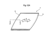
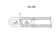
- the cuff having the above structure has an air bag 1 formed in an elongated shape.
- the two sides 3 and 3 which are the long sides of the air bag 1 are formed by bending a single resin sheet. Therefore, when an external force in the direction of arrow A is applied to the air bag 1, the air bag 1 easily rolls in the direction in which the external force acts, causing a lateral shift. That is, the long side 3 of the air bag 1 extends in the direction a1 that receives the external force or is contracted in the direction a2 as shown in the PP cross section of FIG. The position of changes.
- an object of the present invention is to provide a cuff for a blood pressure information measuring device and a blood pressure information measuring device capable of applying a sufficient compression force to a measurement site with a simple configuration.
- the present invention has the following configuration.
- a blood pressure information measurement cuff that has a belt-like cuff body and a fluid bag that is attached to the cuff body and expands and contracts when fluid enters and exits, and is used by being wound around a subject.
- the fluid bag is formed into a rectangular bag shape in which the cylindrical resin sheet is flattened and the both open ends are sealed, Partial welding in which the resin sheet is folded and welded to a part of at least one of the opposing sides of the pair of opposing sides that intersects the sides of the sealed both ends and extends along the winding direction of the subject.
- Blood pressure information measurement cuff formed with a part.
- a blood pressure information acquisition unit for acquiring blood pressure information;
- a blood pressure information measuring device A blood pressure information measuring device.
- a sufficient compression force can be applied to the measurement site with a simple configuration, and high-precision blood pressure measurement can be realized.
- FIG. 7 is a schematic cross-sectional view between QQ of the air bag shown in FIG. 6.
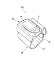
- FIG. 1 is a diagram for explaining an embodiment of the present invention, and is an overall configuration diagram showing a configuration of a blood pressure information measuring device.
- the blood pressure information measurement device (hereinafter, abbreviated as a sphygmomanometer) 100 mainly includes a device body 11 as a blood pressure information acquisition unit and a sphygmomanometer cuff (hereinafter abbreviated as a cuff) 13.
- the illustrated sphygmomanometer 100 is a wrist blood pressure information measuring device that measures blood pressure information such as a blood pressure value in a state where the cuff 13 is worn on the wrist of a subject.
- the blood pressure information includes a blood pressure value, a pulse wave waveform, a heart rate, and the like, a maximum blood pressure value, a minimum blood pressure value, a pulse rate, a pulse wave amplitude, an AI (Augmentation Index) value calculated from them, TR (Time of Reflection) value and the like are included.
- the apparatus main body 11 and the cuff 13 are integrally formed, and the apparatus main body 11 and the cuff 13 are connected from an air connection port provided on the cuff 13 side to the apparatus main body via an air channel (not shown). .
- the apparatus main body 11 is provided with a display unit 19 for displaying information and an input operation unit 21 for inputting various information.
- the display unit 19 displays the blood pressure value, the measurement result of the pulse rate, and the like visually using numerical values, graphs, and the like.
- a liquid crystal panel or the like is used as the display unit 19.
- the input operation unit 21 is provided with a power button, a measurement start button, and various buttons for inputting information on the subject.
- the cuff 13 is formed in a band shape as a whole, and is used by being wrapped around the wrist of the subject.
- the cuff 13 has an air bag 23 which is a fluid bag for pressing the wrist, and a bag-like cover body 25 as a cuff body for wrapping the air bag 23 around the wrist of the subject.
- FIG. 2 is a functional block diagram of the blood pressure information measuring device shown in FIG.
- the apparatus main body 11 is provided with an air system component 27 for blood pressure measurement for supplying or discharging air to / from an air bag 23 contained in the cuff 13.
- the blood pressure measurement air system component 27 includes a pressure sensor 29 that detects the pressure in the air bladder 23, and a pump 33 and a valve 35 that are expansion and contraction mechanisms 31 that inflate and contract the air bladder 23.
- An oscillation circuit 37, a pump drive circuit 39, and a valve drive circuit 41 are provided in the apparatus main body 11 in association with the blood pressure measurement air system component 27.
- the apparatus main body 11 stores a CPU (Central Processing Unit) 43 as a control unit that controls and monitors each unit intensively, various programs such as a program for causing the CPU 43 to perform a predetermined operation, and a measured blood pressure value.
- the memory unit 45, the display unit 19 and the input operation unit 21 described above, and a power source unit 47 that supplies power as a power source to the CPU 43 are provided.
- the CPU 43 also functions as blood pressure value calculation means for calculating blood pressure values.
- the pressure sensor 29 detects the pressure in the air bag 23 (hereinafter referred to as “cuff pressure”), and outputs a signal corresponding to the detected cuff pressure to the oscillation circuit 37.
- the pump 33 supplies air to the air bag 23.
- the valve 35 opens and closes when maintaining the pressure in the air bladder 23 or exhausting the air in the air bladder 23.
- the oscillation circuit 37 outputs a signal having an oscillation frequency corresponding to the output value of the pressure sensor 29 to the CPU 43.
- the pump drive circuit 39 controls the drive of the pump 33 based on a control signal given from the CPU 43.
- the valve drive circuit 41 performs opening / closing control of the valve 35 based on a control signal given from the CPU 43.
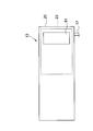
- FIG. 3 is a plan view of the cuff 13.
- the cuff 13 has an air bag 23 and a bag-like cover body 25.
- the bag-like cover body 25 is formed in a bag shape by superimposing two sheet-like members composed of an inner cover and an outer cover and joining the peripheral edges thereof.
- a surface fastener 51 made of, for example, Velcro (registered trademark) is provided on the outside of the cuff 13 and the air bag 23, a surface fastener 51 made of, for example, Velcro (registered trademark) is provided.
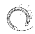
- FIG. 4 is a cross-sectional view showing a state where the cuff 13 is wound around the wrist of the subject.
- a curler 53 may be interposed between the air bag 23 and the bag-like cover body 25.
- the curler 53 is made of a flexible member configured to be elastically deformable in the radial direction by being wound in an annular shape.
- the curler 53 is bonded and fixed to the outer peripheral surface of the air bag 23 via an adhesive member such as a double-sided tape (not shown), and is configured to follow the wrist by maintaining its own annular shape.
- the curler 53 is intended to make it easier for the subject to attach the cuff 13 to the wrist, and to urge the air bag 23 toward the inside of the wrist when the cuff 13 is attached to the wrist.
- the curler 53 is formed of a resin member such as polypropylene (PP) so as to exhibit a sufficient elastic force.
- PP polypropylene
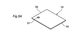
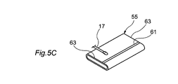
- FIG. 5A, FIG. 5B, FIG. 5C, and FIG. 5D are explanatory views showing a method for manufacturing the air bladder 23.
- FIG. 5A As a manufacturing procedure of the air bag 23, first, as shown in FIG. 5A, one rectangular resin sheet 55 is prepared.
- the resin sheet 55 is a flexible sheet made of, for example, ethylene-vinyl acetate copolymer (EVA), soft vinyl chloride (PVC), polyurethane (PU), natural rubber (NR), or the like.
- EVA ethylene-vinyl acetate copolymer
- PVC soft vinyl chloride
- PU polyurethane
- NR natural rubber
- the other inner surface is formed on one outer surface of the opposite end portions 59, 59 of the resin sheet 55. They are superposed on the inside and outside so as to come into contact with each other, and the overlapping portions are welded by a high frequency welder or the like. Thereby, the resin sheet 55 becomes a cylindrical body, and the 1st welding part 61 along the axial direction of a cylindrical body is formed.
- the cylindrical body processed in FIG. 5B is flattened.
- the flattened resin sheet 55 has both ends 63, 63 of the cylindrical body open.
- the open ends 63 and 63 are welded by a high frequency welder or the like to form second welded portions 65 and 67.
- the air bag 23 manufactured as described above has a rectangular shape in plan view, and the cuff 13 has a long side portion in the circumferential direction when wound around the wrist and a short side portion in the longitudinal direction perpendicular to the circumferential direction. Housed inside.
- the length of the long side part is, for example, 100 mm or more and 220 mm or less, and the length of the short side part can be, for example, 40 mm or more and less than the length of the long side part.
- the air bag 23 can be formed in a square shape or other polygonal shapes.
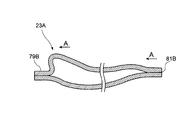
- FIG. 6 is a plan view of the air bag in the first configuration example.
- the air bag 23A of this configuration example has a pair of opposing sides along the winding direction of the subject, long sides 71 and 73, and a pair of short sides 75 and 77 along the direction orthogonal to the winding direction, as viewed in plan view. It is formed in a rectangular shape.
- the air bag 23A is formed with the aforementioned first welded portion 61 and second welded portions 65, 67.
- the air bag 23A has partial welded portions 79A and 79B in which the resin sheet 55 is folded up and down on a part of the long sides 71 and 73 and welded. , 81A, 81B are formed.
- the partial welds 79A and 79B are formed on the long side 71 side, and the partial welds 81A and 81b are formed on the long side 73 side.
- the air bag 23A is formed in a rectangular bag shape in which a cylindrical resin sheet is flattened and both open ends are sealed. At least part of the long sides 71 and 73 (both in the present configuration example) of the pair of opposing sides that cross the sides of the sealed both ends and extend along the winding direction of the subject. Partially welded portions 79A, 79B, 81A, 81B are formed by folding and welding the resin sheets.
- the partial welds 79A, 79B, 81A, 81B are discretely formed on both sides of the long sides 71, 73 with respect to the central region 83 in the winding direction of the air bag 23A.
- the air bag 23A is formed in a rectangular shape having a pair of opposing sides as long sides and a pair of opposing sides along a direction orthogonal to the winding direction as short sides.
- the partial welded portion 79A is formed in the first end region AL1 which is one side of the central region 83 on the long side 71, and the partial welded portion 79B is formed in the second end region AR1 which is the other side. It is formed.
- the partial welded portion 81A is formed in the first end region AL2 that is one side of the central region 83 on the long side 71, and the partial welded portion 81B is the second end region that is the other side. Formed in AR2.
- the partial weld portion 79A is formed at the boundary position between the central region 83 and the first end region AL1
- the partial weld portion 79B is formed at the boundary position between the central region 83 and the second end region AR1.
- the partial weld 81A is formed at the boundary position between the central region 83 and the first end region AL2
- the partial weld 81B is formed at the boundary position between the central region 83 and the second end region AR2.
- each partial weld part 79A, 79B, 81A, 81B is formed alternately along the winding direction (direction along the long side).
- the partial welded portions 79A, 79B, 81A, 81B are formed at positions that are biased near both ends except for the central region 83 of the long sides 71, 73 so that the measurement site can be compressed with sufficient force. Is done.
- a partial welded portion is formed in the central region 83.
- the expansion of the central portion of the air bag 23A is not hindered.
- the partial welded portions 79A, 79B, 81A, 81B are provided in the vicinity of the central region 83 that avoids the central region 83, it is possible to sufficiently secure the compression area for the portion of the subject that is most desired to be compressed.
- the partial welds 79A and 79B in this configuration example are formed with a distance La from the center line Lc, and the partial welds 81A and 81B are formed with a distance Lb longer than the distance La from the stop line or Lc.
- the central region 83 is defined in a trapezoidal shape, and a long side 73 serving as the longer base is disposed on the proximal side (side closer to the trunk) of the subject. Further, the shorter long side 71 is arranged on the distal side of the subject (the side far from the trunk).
- the partial welded portions 79A, 79B, 81A, 81B prevent the lateral displacement along the short sides 75, 77 of the air bag 23A.
- the partial welded portion 79B prevents the extension in the direction a1 shown in FIG. 12B.
- the partially welded portion 81B prevents degeneration in the direction a2 shown in FIG. 12B.
- the welding margin width W3 in the direction orthogonal to the outer edge sides (long sides 71 and 73) of the air bag 23A is the welding margin width W1 from the edge portion of the first welding portion 61, the second welding portion 65, It is preferable that the welding allowance width W2 from the edge portion 67 is narrower. By narrowing the welding allowance width W3, the influence on the inflation of the air bag 23A can be minimized.
- the shape of the partially welded portions 79A, 79B, 81A, 81B is not limited to the rectangular shape in the illustrated example, but may be other shapes.
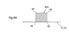
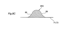
- 8A, 8B, 8C, and 8D are plan views showing variations in the shape of the partially welded portion.
- 8A is a partial welded portion 85A having a square shape
- FIG. 8B is a partially welded portion 85B having a shape including a semicircular portion
- FIG. 8C is a partially welded portion 85C having a shape having an expanded base
- FIG. 8D is a partial weld having a trapezoidal shape. This is the case of the part 85D.
- the partial welded portion can obtain the above effect regardless of the shape. Further, when the semicircular portion 87 shown in FIG. 8B, the skirt portion 89 shown in FIG. 8C, and the trapezoid hypotenuse 91 shown in FIG. 8D are formed, the air bag 23A in the corner portion 93 shown in FIG. The stress concentration can be alleviated and the durability of the air bag 23A can be further improved.
- the partially welded portions having various shapes are alternately formed along the winding direction on the long sides 71 and 73 which are a pair of opposite sides of the air bag 23A. That is, the center position of each partial welded portion is disposed at a different position with respect to the directions of the short sides 75 and 77 when the air bag 23A is viewed in plan. Thereby, it is possible to prevent wrinkles from occurring in the air bag 23A when the air bag 23A is inflated.
- the arrangement position and size of the partially welded portion can be exemplified as follows for the partially welded portion shown in FIG. 6, for example. Assuming that the central region 83 of the air bag 23A corresponding to the region to be most compressed of the subject is within a range of 60 mm near the center line Lc of the air bag 23A, the partially welded portions 79A, 79B. 81A and 81B can be about 3 mm in the circumferential direction (long side direction) when wound around the subject and about 1 mm in the short side direction orthogonal to the circumferential direction. Further, these rectangular partial welds 79A, 79B, 81A, 81B can be alternately formed along the long sides 71, 73, for example, at an interval of 8 mm at the center of the weld.
- FIG. 9 shows a modification of the arrangement of the partial welds.
- the partial welded portion may be arranged in the vicinity of the central region 83 of the air bag 23A. That is, the partial welds 95A and 95B shown in FIG. 9 are formed outside the central region 83, but the partial welds 97A and 97B are disposed in the central region 83 in the vicinity of the central region 83. Also good.
- the partial welded portions 95A, 95B, 97A, and 97B are formed by dividing the trapezoidal partial welded portion shown in FIG. 8D into two parts, and the trapezoidal oblique sides coincide with the boundary line of the central region 83.
- the long side width W4 of the welding allowance can be narrowed by arranging the partial welded portions 95A, 95B, 97A, 97B in consideration of the taper of the trapezoid oblique sides.
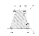
- FIG. 10 is a plan view of an air bag in the second configuration example.
- the air bag 23 ⁇ / b> B of this configuration example forms partial welded portions 99 ⁇ / b> A, 99 ⁇ / b> B, 101 ⁇ / b> A, 101 ⁇ / b> B continuous along the long sides 71, 73 on the long sides 71, 73 excluding the central region 83.
- One end of the partial weld 99A is connected to the second weld 65 on the long side 71 of the air bag 23B, and the other end extends continuously to the boundary with the central region 83.
- the partial weld 99B is connected to the second weld 67 and extends continuously to the boundary with the central region 83.
- the partial welds 101 ⁇ / b> A and 101 ⁇ / b> B are connected to the second welds 65 and 67 and extend continuously to the boundary with the central region 83.
- the welding allowance width W5 from the edge portions (71, 73) of these partial weld portions 99A, 99B, 101A, 101B is the welding allowance width W1, from the edge portion of the first weld portion 61, the second weld portion 65, It is formed narrower than the welding allowance width W2 from the edge of 67.
- the welding allowance width W5 is set to be 70% to 90% of the welding allowance widths W1 and W2.
- the continuous partial welded portions 99A, 99B, 101A, 101B can more reliably prevent the occurrence of lateral displacement, and a sufficient compression force can be applied to the measurement site.
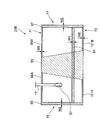
- FIG. 11 is a plan view showing a cuff in the third configuration example.
- the cuff 13A has a shape in which one long side 105 of the belt-like shape is curved longer than the other long side 107 in consideration of the state of being wound around the subject.
- the long side 105 is disposed on the proximal side (the side closer to the trunk) of the subject, and the shorter long side 107 is disposed on the distal side (the side far from the trunk).
- the air bag 23C accommodated in the cuff 13A in this case forms the partial welded portions 103A and 103B only on the long side 73 disposed on the long side 105 side of the cuff 13A, and the partial weld on the opposite long side 107. Does not form part.
- the air bag 23 ⁇ / b> C may have a configuration in which a partial weld portion having a welding allowance narrower than the long side 105 is formed on the long side 107.
- a partial weld portion having a welding allowance narrower than the long side 105 is formed on the long side 107.
- the welding margin width of the partial welded portion of the long side 107 is 0.8 mm, and the portion on the long side 105 side
- the welding area of the welded portion can be made relatively larger than the partial welded portion on the long side 107 side.
- the present invention is not limited to the above-described embodiments, and the configurations of the embodiments may be combined with each other, or may be modified or applied by those skilled in the art based on the description of the specification and well-known techniques.
- the invention is intended and is within the scope of seeking protection.
- the above blood pressure information measurement device has been described by taking a wrist type as an example, the present invention is not limited to the wrist type, and may have a device configuration applicable to any of the four limbs.
- a blood pressure information measurement cuff that has a belt-like cuff body and a fluid bag that is attached to the cuff body and expands and contracts when fluid enters and exits, and is used by being wound around a subject.
- the fluid bag is formed into a rectangular bag shape in which the cylindrical resin sheet is flattened and the both open ends are sealed, Partial welding in which the resin sheet is folded and welded to a part of at least one of the opposing sides of the pair of opposing sides that intersects the sides of the sealed both ends and extends along the winding direction of the subject.
- Blood pressure information measurement cuff formed with a part.
- the blood pressure information measurement cuff of (1) The partial welded portion is a blood pressure information measurement cuff formed on both sides of the opposite side with respect to a central region in the winding direction of the fluid bag.
- the blood pressure information measurement cuff according to (2) The fluid bag is formed in a rectangular shape having the pair of opposed sides as long sides and the pair of opposed sides along a direction orthogonal to the winding direction as short sides,
- the partial welded portions are cuffs for measuring blood pressure information that are respectively formed in a first end region on one side of the central region on the long side and a second end region on the other side. .
- the blood pressure information measurement cuff of (3), The partial welded portion is a blood pressure information measurement cuff formed discretely in each of the first end region and the second end region.
- the blood pressure information measurement cuff according to (4), The partial weld portion is a blood pressure information measurement cuff formed at a boundary position between the central region and the first end region and a boundary position between the central region and the second end region.
- the blood pressure information measurement cuff according to (3), The partial welded portion is a blood pressure information measurement cuff that extends over the entire first end region and the second end region.
- the blood pressure information measurement cuff according to any one of (1) to (6),
- the fluid bag is formed by flattening the cylindrical body with respect to the cylindrical body having the first welded portion where the edges of the pair of opposite sides of the rectangular resin sheet are overlapped, and the remaining bag opening.
- a cuff for measuring blood pressure information which has a second welded portion in which two edge portions are welded, and is formed in a bag shape.
- the blood pressure information measurement cuff according to (7), The partial weld portion is for measuring blood pressure information in which a welding margin width in a direction orthogonal to a side of an outer edge of the welded fluid bag is narrower than the welding margin width with respect to the first welding portion and the second welding portion. Cuff.
- the blood pressure information measurement cuff according to any one of (1) to (8), The partial weld portion is a blood pressure information measurement cuff formed on both of the pair of opposing sides.
- the blood pressure information measurement cuff according to (9), The partial welded portions are blood pressure information measurement cuffs that are alternately formed on the pair of opposing sides along the winding direction.
- the blood pressure information measurement cuff according to any one of (1) to (10), The cuff body has a curved shape in which one of the pair of long sides in a band shape is longer than the other, The partial welded portion is for blood pressure information measurement formed only on the opposite side disposed on the longer long side of the cuff body among the pair of opposite sides of the fluid bag accommodated in the cuff body.
- the blood pressure information measurement cuff according to any one of (1) to (10),
- the cuff body has a curved shape in which one of the pair of long sides in a band shape is longer than the other, Of the pair of opposing sides of the fluid bag accommodated in the cuff body, the partial welded portion has a welding area of the opposing side disposed on the longer long side of the cuff body on the other side. Blood pressure information measurement cuff larger than the welding area of the opposite side to be arranged.
- the cuff for a blood pressure information measuring device and the blood pressure information measuring device of the present invention are useful when used for a wrist type blood pressure information measuring device that measures blood pressure information such as blood pressure values while being worn on the wrist of a subject, for example.
- a wrist type blood pressure information measuring device that measures blood pressure information such as blood pressure values while being worn on the wrist of a subject, for example.
Landscapes
- Health & Medical Sciences (AREA)
- Life Sciences & Earth Sciences (AREA)
- Vascular Medicine (AREA)
- Cardiology (AREA)
- Engineering & Computer Science (AREA)
- Biophysics (AREA)
- General Health & Medical Sciences (AREA)
- Veterinary Medicine (AREA)
- Physics & Mathematics (AREA)
- Public Health (AREA)
- Animal Behavior & Ethology (AREA)
- Pathology (AREA)
- Biomedical Technology (AREA)
- Heart & Thoracic Surgery (AREA)
- Medical Informatics (AREA)
- Molecular Biology (AREA)
- Surgery (AREA)
- Ophthalmology & Optometry (AREA)
- Dentistry (AREA)
- Physiology (AREA)
- Mechanical Engineering (AREA)
- Measuring Pulse, Heart Rate, Blood Pressure Or Blood Flow (AREA)
Priority Applications (4)
| Application Number | Priority Date | Filing Date | Title |
|---|---|---|---|
| DE112013004679.2T DE112013004679T5 (de) | 2012-09-25 | 2013-08-08 | Blutdruckinformationsmessgerätmanschette und Blutdruckinformationsmessgerät |
| CN201380049842.XA CN104661589B (zh) | 2012-09-25 | 2013-08-08 | 血压信息测量装置用袖带及血压信息测量装置 |
| US14/644,962 US20150182138A1 (en) | 2012-09-25 | 2015-03-11 | Blood pressure information measurement apparatus cuff and blood pressure information measurement apparatus |
| US16/273,602 US11432729B2 (en) | 2012-09-25 | 2019-02-12 | Blood pressure information measurement apparatus cuff and blood pressure information measurement apparatus |
Applications Claiming Priority (2)
| Application Number | Priority Date | Filing Date | Title |
|---|---|---|---|
| JP2012-211137 | 2012-09-25 | ||
| JP2012211137A JP6051732B2 (ja) | 2012-09-25 | 2012-09-25 | 血圧情報測定装置用カフ及び血圧情報測定装置 |
Related Child Applications (1)
| Application Number | Title | Priority Date | Filing Date |
|---|---|---|---|
| US14/644,962 Continuation US20150182138A1 (en) | 2012-09-25 | 2015-03-11 | Blood pressure information measurement apparatus cuff and blood pressure information measurement apparatus |
Publications (1)
| Publication Number | Publication Date |
|---|---|
| WO2014050325A1 true WO2014050325A1 (ja) | 2014-04-03 |
Family
ID=50387739
Family Applications (1)
| Application Number | Title | Priority Date | Filing Date |
|---|---|---|---|
| PCT/JP2013/071528 Ceased WO2014050325A1 (ja) | 2012-09-25 | 2013-08-08 | 血圧情報測定装置用カフ及び血圧情報測定装置 |
Country Status (5)
| Country | Link |
|---|---|
| US (2) | US20150182138A1 (enExample) |
| JP (1) | JP6051732B2 (enExample) |
| CN (1) | CN104661589B (enExample) |
| DE (1) | DE112013004679T5 (enExample) |
| WO (1) | WO2014050325A1 (enExample) |
Cited By (1)
| Publication number | Priority date | Publication date | Assignee | Title |
|---|---|---|---|---|
| JP2020092885A (ja) * | 2018-12-13 | 2020-06-18 | オムロン株式会社 | 血圧測定装置 |
Families Citing this family (8)
| Publication number | Priority date | Publication date | Assignee | Title |
|---|---|---|---|---|
| JP6558119B2 (ja) * | 2015-07-24 | 2019-08-14 | オムロンヘルスケア株式会社 | 流体袋、流体袋製造方法、血圧測定用カフ、および血圧計 |
| USD806250S1 (en) * | 2015-12-07 | 2017-12-26 | Samsung Electronics Co., Ltd. | Medical device |
| JP6849488B2 (ja) * | 2017-03-07 | 2021-03-24 | オムロン株式会社 | 血圧計、血圧測定方法および機器 |
| JP6976841B2 (ja) * | 2017-12-28 | 2021-12-08 | オムロン株式会社 | 血圧測定装置 |
| JP7019425B2 (ja) * | 2018-01-15 | 2022-02-15 | オムロン株式会社 | 血圧測定装置及び血圧測定装置の製造方法 |
| JP7091831B2 (ja) * | 2018-05-24 | 2022-06-28 | オムロンヘルスケア株式会社 | センサモジュール、センサモジュールの製造方法、及び血圧測定装置 |
| JP6751462B1 (ja) * | 2019-07-24 | 2020-09-02 | シチズン時計株式会社 | 血圧計用カフ |
| CN114403829A (zh) * | 2022-01-21 | 2022-04-29 | 深圳金亿帝医疗设备股份有限公司 | 一种血压手表 |
Citations (3)
| Publication number | Priority date | Publication date | Assignee | Title |
|---|---|---|---|---|
| JPH02299635A (ja) * | 1989-05-15 | 1990-12-11 | Matsushita Electric Works Ltd | 手首用血圧計のカフ帯 |
| JPH0564631A (ja) * | 1991-09-06 | 1993-03-19 | Sharp Corp | 血圧計用カフの空気袋 |
| JP2006130331A (ja) * | 2005-12-28 | 2006-05-25 | Omron Healthcare Co Ltd | 血圧計用カフ |
Family Cites Families (13)
| Publication number | Priority date | Publication date | Assignee | Title |
|---|---|---|---|---|
| US4979953A (en) * | 1990-02-16 | 1990-12-25 | Instrumed, Inc. | Medical disposable inflatable tourniquet cuff |
| JPH0467837A (ja) | 1990-07-09 | 1992-03-03 | Terumo Corp | 血圧測定用腕帯用空気袋 |
| US5193549A (en) * | 1990-07-11 | 1993-03-16 | Biomedical Dynamics Corporation | Inflatable cuff |
| JP2711421B2 (ja) * | 1991-12-04 | 1998-02-10 | シャープ株式会社 | 血圧計カフ帯用の空気袋 |
| JP3342465B2 (ja) * | 2000-03-06 | 2002-11-11 | 日本コーリン株式会社 | 自動血圧測定装置 |
| JP2003052651A (ja) | 2001-08-10 | 2003-02-25 | Tk Inc Co | 血圧計のカフ用空気袋の製造方法 |
| EP1594752B1 (en) * | 2002-12-16 | 2007-03-28 | Velcro Industries B.V. | Attachable bags |
| US20060027946A1 (en) * | 2004-08-04 | 2006-02-09 | Tk Incorporated | Producing method for air bag |
| CN1732842A (zh) * | 2004-08-11 | 2006-02-15 | 株式会社Tk | 气囊的制造方法 |
| JP4654641B2 (ja) * | 2004-09-15 | 2011-03-23 | オムロンヘルスケア株式会社 | 血圧計用カフ |
| JP2007054341A (ja) * | 2005-08-25 | 2007-03-08 | Csp Kk | 血圧計の腕帯及び血圧計の腕帯の空気袋の製造方法 |
| US7758607B2 (en) * | 2006-03-20 | 2010-07-20 | Mcewen James A | Low-cost contour cuff for surgical tourniquet systems |
| JP4685951B2 (ja) * | 2009-06-09 | 2011-05-18 | シチズン・システムズ株式会社 | 血圧計用カフの製造方法 |
-
2012
- 2012-09-25 JP JP2012211137A patent/JP6051732B2/ja active Active
-
2013
- 2013-08-08 DE DE112013004679.2T patent/DE112013004679T5/de active Pending
- 2013-08-08 CN CN201380049842.XA patent/CN104661589B/zh active Active
- 2013-08-08 WO PCT/JP2013/071528 patent/WO2014050325A1/ja not_active Ceased
-
2015
- 2015-03-11 US US14/644,962 patent/US20150182138A1/en not_active Abandoned
-
2019
- 2019-02-12 US US16/273,602 patent/US11432729B2/en active Active
Patent Citations (3)
| Publication number | Priority date | Publication date | Assignee | Title |
|---|---|---|---|---|
| JPH02299635A (ja) * | 1989-05-15 | 1990-12-11 | Matsushita Electric Works Ltd | 手首用血圧計のカフ帯 |
| JPH0564631A (ja) * | 1991-09-06 | 1993-03-19 | Sharp Corp | 血圧計用カフの空気袋 |
| JP2006130331A (ja) * | 2005-12-28 | 2006-05-25 | Omron Healthcare Co Ltd | 血圧計用カフ |
Cited By (2)
| Publication number | Priority date | Publication date | Assignee | Title |
|---|---|---|---|---|
| JP2020092885A (ja) * | 2018-12-13 | 2020-06-18 | オムロン株式会社 | 血圧測定装置 |
| JP7175738B2 (ja) | 2018-12-13 | 2022-11-21 | オムロン株式会社 | 血圧測定装置 |
Also Published As
| Publication number | Publication date |
|---|---|
| CN104661589B (zh) | 2017-04-12 |
| US11432729B2 (en) | 2022-09-06 |
| JP2014064664A (ja) | 2014-04-17 |
| CN104661589A (zh) | 2015-05-27 |
| US20150182138A1 (en) | 2015-07-02 |
| DE112013004679T5 (de) | 2015-08-13 |
| US20190167127A1 (en) | 2019-06-06 |
| JP6051732B2 (ja) | 2016-12-27 |
Similar Documents
| Publication | Publication Date | Title |
|---|---|---|
| JP6051732B2 (ja) | 血圧情報測定装置用カフ及び血圧情報測定装置 | |
| JP4742576B2 (ja) | 血圧計用カフおよびこれを備えた血圧計 | |
| JP4595525B2 (ja) | 血圧計用カフおよびこれを備えた血圧計 | |
| JP4595573B2 (ja) | 血圧計用カフおよびその製造方法ならびに血圧計 | |
| JP4665757B2 (ja) | 血圧計用カフおよびこれを備えた血圧計 | |
| CN1748637B (zh) | 血压计用袖带 | |
| TWI532464B (zh) | 血壓資訊測量裝置用壓脈帶及具備壓脈帶之血壓資訊測量裝置 | |
| JP5145930B2 (ja) | 血圧計用カフおよび血圧計 | |
| JP2006218178A (ja) | 血圧計用カフおよび血圧計 | |
| CN102770065B (zh) | 血压信息测定装置用袖带及具有该袖带的血压信息测定装置 | |
| JP5487963B2 (ja) | 血圧情報測定装置用カフおよびこれを備えた血圧情報測定装置 | |
| JP2006081668A (ja) | 血圧計用カフ | |
| JP2007275483A (ja) | 血圧計用カフ | |
| JP3168376U (ja) | 血圧情報測定装置用カフおよびこれを備えた血圧情報測定装置 | |
| JP2007275484A (ja) | 血圧計用カフ |
Legal Events
| Date | Code | Title | Description |
|---|---|---|---|
| 121 | Ep: the epo has been informed by wipo that ep was designated in this application |
Ref document number: 13842823 Country of ref document: EP Kind code of ref document: A1 |
|
| DPE2 | Request for preliminary examination filed before expiration of 19th month from priority date (pct application filed from 20040101) | ||
| WWE | Wipo information: entry into national phase |
Ref document number: 112013004679 Country of ref document: DE Ref document number: 1120130046792 Country of ref document: DE |
|
| 122 | Ep: pct application non-entry in european phase |
Ref document number: 13842823 Country of ref document: EP Kind code of ref document: A1 |