WO2014050231A1 - 円筒型タンクの構築方法 - Google Patents
円筒型タンクの構築方法 Download PDFInfo
- Publication number
- WO2014050231A1 WO2014050231A1 PCT/JP2013/067190 JP2013067190W WO2014050231A1 WO 2014050231 A1 WO2014050231 A1 WO 2014050231A1 JP 2013067190 W JP2013067190 W JP 2013067190W WO 2014050231 A1 WO2014050231 A1 WO 2014050231A1
- Authority
- WO
- WIPO (PCT)
- Prior art keywords
- tank
- side plate
- inner tank
- jack
- plate
- Prior art date
- Legal status (The legal status is an assumption and is not a legal conclusion. Google has not performed a legal analysis and makes no representation as to the accuracy of the status listed.)
- Ceased
Links
Images








Classifications
-
- E—FIXED CONSTRUCTIONS
- E04—BUILDING
- E04H—BUILDINGS OR LIKE STRUCTURES FOR PARTICULAR PURPOSES; SWIMMING OR SPLASH BATHS OR POOLS; MASTS; FENCING; TENTS OR CANOPIES, IN GENERAL
- E04H7/00—Construction or assembling of bulk storage containers employing civil engineering techniques in situ or off the site
- E04H7/02—Containers for fluids or gases; Supports therefor
- E04H7/04—Containers for fluids or gases; Supports therefor mainly of metal
- E04H7/06—Containers for fluids or gases; Supports therefor mainly of metal with vertical axis
-
- E—FIXED CONSTRUCTIONS
- E04—BUILDING
- E04H—BUILDINGS OR LIKE STRUCTURES FOR PARTICULAR PURPOSES; SWIMMING OR SPLASH BATHS OR POOLS; MASTS; FENCING; TENTS OR CANOPIES, IN GENERAL
- E04H5/00—Buildings or groups of buildings for industrial or agricultural purposes
- E04H5/10—Buildings forming part of cooling plants
-
- E—FIXED CONSTRUCTIONS
- E04—BUILDING
- E04H—BUILDINGS OR LIKE STRUCTURES FOR PARTICULAR PURPOSES; SWIMMING OR SPLASH BATHS OR POOLS; MASTS; FENCING; TENTS OR CANOPIES, IN GENERAL
- E04H7/00—Construction or assembling of bulk storage containers employing civil engineering techniques in situ or off the site
- E04H7/02—Containers for fluids or gases; Supports therefor
- E04H7/18—Containers for fluids or gases; Supports therefor mainly of concrete, e.g. reinforced concrete, or other stone-like material
-
- F—MECHANICAL ENGINEERING; LIGHTING; HEATING; WEAPONS; BLASTING
- F17—STORING OR DISTRIBUTING GASES OR LIQUIDS
- F17C—VESSELS FOR CONTAINING OR STORING COMPRESSED, LIQUEFIED OR SOLIDIFIED GASES; FIXED-CAPACITY GAS-HOLDERS; FILLING VESSELS WITH, OR DISCHARGING FROM VESSELS, COMPRESSED, LIQUEFIED, OR SOLIDIFIED GASES
- F17C3/00—Vessels not under pressure
- F17C3/02—Vessels not under pressure with provision for thermal insulation
- F17C3/022—Land-based bulk storage containers
-
- F—MECHANICAL ENGINEERING; LIGHTING; HEATING; WEAPONS; BLASTING
- F17—STORING OR DISTRIBUTING GASES OR LIQUIDS
- F17C—VESSELS FOR CONTAINING OR STORING COMPRESSED, LIQUEFIED OR SOLIDIFIED GASES; FIXED-CAPACITY GAS-HOLDERS; FILLING VESSELS WITH, OR DISCHARGING FROM VESSELS, COMPRESSED, LIQUEFIED, OR SOLIDIFIED GASES
- F17C2201/00—Vessel construction, in particular geometry, arrangement or size
- F17C2201/01—Shape
- F17C2201/0104—Shape cylindrical
- F17C2201/0109—Shape cylindrical with exteriorly curved end-piece
-
- F—MECHANICAL ENGINEERING; LIGHTING; HEATING; WEAPONS; BLASTING
- F17—STORING OR DISTRIBUTING GASES OR LIQUIDS
- F17C—VESSELS FOR CONTAINING OR STORING COMPRESSED, LIQUEFIED OR SOLIDIFIED GASES; FIXED-CAPACITY GAS-HOLDERS; FILLING VESSELS WITH, OR DISCHARGING FROM VESSELS, COMPRESSED, LIQUEFIED, OR SOLIDIFIED GASES
- F17C2201/00—Vessel construction, in particular geometry, arrangement or size
- F17C2201/01—Shape
- F17C2201/0104—Shape cylindrical
- F17C2201/0119—Shape cylindrical with flat end-piece
-
- F—MECHANICAL ENGINEERING; LIGHTING; HEATING; WEAPONS; BLASTING
- F17—STORING OR DISTRIBUTING GASES OR LIQUIDS
- F17C—VESSELS FOR CONTAINING OR STORING COMPRESSED, LIQUEFIED OR SOLIDIFIED GASES; FIXED-CAPACITY GAS-HOLDERS; FILLING VESSELS WITH, OR DISCHARGING FROM VESSELS, COMPRESSED, LIQUEFIED, OR SOLIDIFIED GASES
- F17C2201/00—Vessel construction, in particular geometry, arrangement or size
- F17C2201/03—Orientation
- F17C2201/032—Orientation with substantially vertical main axis
-
- F—MECHANICAL ENGINEERING; LIGHTING; HEATING; WEAPONS; BLASTING
- F17—STORING OR DISTRIBUTING GASES OR LIQUIDS
- F17C—VESSELS FOR CONTAINING OR STORING COMPRESSED, LIQUEFIED OR SOLIDIFIED GASES; FIXED-CAPACITY GAS-HOLDERS; FILLING VESSELS WITH, OR DISCHARGING FROM VESSELS, COMPRESSED, LIQUEFIED, OR SOLIDIFIED GASES
- F17C2201/00—Vessel construction, in particular geometry, arrangement or size
- F17C2201/05—Size
- F17C2201/052—Size large (>1000 m3)
-
- F—MECHANICAL ENGINEERING; LIGHTING; HEATING; WEAPONS; BLASTING
- F17—STORING OR DISTRIBUTING GASES OR LIQUIDS
- F17C—VESSELS FOR CONTAINING OR STORING COMPRESSED, LIQUEFIED OR SOLIDIFIED GASES; FIXED-CAPACITY GAS-HOLDERS; FILLING VESSELS WITH, OR DISCHARGING FROM VESSELS, COMPRESSED, LIQUEFIED, OR SOLIDIFIED GASES
- F17C2203/00—Vessel construction, in particular walls or details thereof
- F17C2203/03—Thermal insulations
- F17C2203/0304—Thermal insulations by solid means
- F17C2203/0337—Granular
- F17C2203/0341—Perlite
-
- F—MECHANICAL ENGINEERING; LIGHTING; HEATING; WEAPONS; BLASTING
- F17—STORING OR DISTRIBUTING GASES OR LIQUIDS
- F17C—VESSELS FOR CONTAINING OR STORING COMPRESSED, LIQUEFIED OR SOLIDIFIED GASES; FIXED-CAPACITY GAS-HOLDERS; FILLING VESSELS WITH, OR DISCHARGING FROM VESSELS, COMPRESSED, LIQUEFIED, OR SOLIDIFIED GASES
- F17C2203/00—Vessel construction, in particular walls or details thereof
- F17C2203/06—Materials for walls or layers thereof; Properties or structures of walls or their materials
- F17C2203/0634—Materials for walls or layers thereof
- F17C2203/0636—Metals
- F17C2203/0648—Alloys or compositions of metals
-
- F—MECHANICAL ENGINEERING; LIGHTING; HEATING; WEAPONS; BLASTING
- F17—STORING OR DISTRIBUTING GASES OR LIQUIDS
- F17C—VESSELS FOR CONTAINING OR STORING COMPRESSED, LIQUEFIED OR SOLIDIFIED GASES; FIXED-CAPACITY GAS-HOLDERS; FILLING VESSELS WITH, OR DISCHARGING FROM VESSELS, COMPRESSED, LIQUEFIED, OR SOLIDIFIED GASES
- F17C2203/00—Vessel construction, in particular walls or details thereof
- F17C2203/06—Materials for walls or layers thereof; Properties or structures of walls or their materials
- F17C2203/0634—Materials for walls or layers thereof
- F17C2203/0678—Concrete
-
- F—MECHANICAL ENGINEERING; LIGHTING; HEATING; WEAPONS; BLASTING
- F17—STORING OR DISTRIBUTING GASES OR LIQUIDS
- F17C—VESSELS FOR CONTAINING OR STORING COMPRESSED, LIQUEFIED OR SOLIDIFIED GASES; FIXED-CAPACITY GAS-HOLDERS; FILLING VESSELS WITH, OR DISCHARGING FROM VESSELS, COMPRESSED, LIQUEFIED, OR SOLIDIFIED GASES
- F17C2209/00—Vessel construction, in particular methods of manufacturing
- F17C2209/23—Manufacturing of particular parts or at special locations
- F17C2209/232—Manufacturing of particular parts or at special locations of walls
-
- F—MECHANICAL ENGINEERING; LIGHTING; HEATING; WEAPONS; BLASTING
- F17—STORING OR DISTRIBUTING GASES OR LIQUIDS
- F17C—VESSELS FOR CONTAINING OR STORING COMPRESSED, LIQUEFIED OR SOLIDIFIED GASES; FIXED-CAPACITY GAS-HOLDERS; FILLING VESSELS WITH, OR DISCHARGING FROM VESSELS, COMPRESSED, LIQUEFIED, OR SOLIDIFIED GASES
- F17C2209/00—Vessel construction, in particular methods of manufacturing
- F17C2209/23—Manufacturing of particular parts or at special locations
- F17C2209/234—Manufacturing of particular parts or at special locations of closing end pieces, e.g. caps
-
- F—MECHANICAL ENGINEERING; LIGHTING; HEATING; WEAPONS; BLASTING
- F17—STORING OR DISTRIBUTING GASES OR LIQUIDS
- F17C—VESSELS FOR CONTAINING OR STORING COMPRESSED, LIQUEFIED OR SOLIDIFIED GASES; FIXED-CAPACITY GAS-HOLDERS; FILLING VESSELS WITH, OR DISCHARGING FROM VESSELS, COMPRESSED, LIQUEFIED, OR SOLIDIFIED GASES
- F17C2209/00—Vessel construction, in particular methods of manufacturing
- F17C2209/23—Manufacturing of particular parts or at special locations
- F17C2209/234—Manufacturing of particular parts or at special locations of closing end pieces, e.g. caps
- F17C2209/236—Apparatus therefore
-
- F—MECHANICAL ENGINEERING; LIGHTING; HEATING; WEAPONS; BLASTING
- F17—STORING OR DISTRIBUTING GASES OR LIQUIDS
- F17C—VESSELS FOR CONTAINING OR STORING COMPRESSED, LIQUEFIED OR SOLIDIFIED GASES; FIXED-CAPACITY GAS-HOLDERS; FILLING VESSELS WITH, OR DISCHARGING FROM VESSELS, COMPRESSED, LIQUEFIED, OR SOLIDIFIED GASES
- F17C2221/00—Handled fluid, in particular type of fluid
- F17C2221/03—Mixtures
- F17C2221/032—Hydrocarbons
- F17C2221/033—Methane, e.g. natural gas, CNG, LNG, GNL, GNC, PLNG
-
- F—MECHANICAL ENGINEERING; LIGHTING; HEATING; WEAPONS; BLASTING
- F17—STORING OR DISTRIBUTING GASES OR LIQUIDS
- F17C—VESSELS FOR CONTAINING OR STORING COMPRESSED, LIQUEFIED OR SOLIDIFIED GASES; FIXED-CAPACITY GAS-HOLDERS; FILLING VESSELS WITH, OR DISCHARGING FROM VESSELS, COMPRESSED, LIQUEFIED, OR SOLIDIFIED GASES
- F17C2221/00—Handled fluid, in particular type of fluid
- F17C2221/03—Mixtures
- F17C2221/032—Hydrocarbons
- F17C2221/035—Propane butane, e.g. LPG, GPL
-
- F—MECHANICAL ENGINEERING; LIGHTING; HEATING; WEAPONS; BLASTING
- F17—STORING OR DISTRIBUTING GASES OR LIQUIDS
- F17C—VESSELS FOR CONTAINING OR STORING COMPRESSED, LIQUEFIED OR SOLIDIFIED GASES; FIXED-CAPACITY GAS-HOLDERS; FILLING VESSELS WITH, OR DISCHARGING FROM VESSELS, COMPRESSED, LIQUEFIED, OR SOLIDIFIED GASES
- F17C2223/00—Handled fluid before transfer, i.e. state of fluid when stored in the vessel or before transfer from the vessel
- F17C2223/01—Handled fluid before transfer, i.e. state of fluid when stored in the vessel or before transfer from the vessel characterised by the phase
- F17C2223/0146—Two-phase
- F17C2223/0153—Liquefied gas, e.g. LPG, GPL
-
- F—MECHANICAL ENGINEERING; LIGHTING; HEATING; WEAPONS; BLASTING
- F17—STORING OR DISTRIBUTING GASES OR LIQUIDS
- F17C—VESSELS FOR CONTAINING OR STORING COMPRESSED, LIQUEFIED OR SOLIDIFIED GASES; FIXED-CAPACITY GAS-HOLDERS; FILLING VESSELS WITH, OR DISCHARGING FROM VESSELS, COMPRESSED, LIQUEFIED, OR SOLIDIFIED GASES
- F17C2223/00—Handled fluid before transfer, i.e. state of fluid when stored in the vessel or before transfer from the vessel
- F17C2223/01—Handled fluid before transfer, i.e. state of fluid when stored in the vessel or before transfer from the vessel characterised by the phase
- F17C2223/0146—Two-phase
- F17C2223/0153—Liquefied gas, e.g. LPG, GPL
- F17C2223/0161—Liquefied gas, e.g. LPG, GPL cryogenic, e.g. LNG, GNL, PLNG
-
- F—MECHANICAL ENGINEERING; LIGHTING; HEATING; WEAPONS; BLASTING
- F17—STORING OR DISTRIBUTING GASES OR LIQUIDS
- F17C—VESSELS FOR CONTAINING OR STORING COMPRESSED, LIQUEFIED OR SOLIDIFIED GASES; FIXED-CAPACITY GAS-HOLDERS; FILLING VESSELS WITH, OR DISCHARGING FROM VESSELS, COMPRESSED, LIQUEFIED, OR SOLIDIFIED GASES
- F17C2270/00—Applications
- F17C2270/01—Applications for fluid transport or storage
- F17C2270/0134—Applications for fluid transport or storage placed above the ground
Definitions
- the present invention relates to a method for constructing a cylindrical tank. This application claims priority based on Japanese Patent Application No. 2012-215615 for which it applied to Japan on September 28, 2012, and uses the content here.
- a cylindrical shell with a double shell structure having an inner tank and an outer tank is used for storing low-temperature liquids such as LNG (liquefied natural gas) and LPG (liquefied petroleum gas).
- Patent Document 1 discloses a cylindrical tank having a metal inner tank and a concrete outer tank.
- Patent Document 1 discloses a technique in which a metal inner tank and a concrete outer tank are simultaneously constructed in order to shorten the construction period of a cylindrical tank. Specifically, a jack stand is erected at the bottom of the outer tub, and the jack-up device is supported at a predetermined height (see FIG. 4B of Patent Document 1). And when performing the side wall construction of the outer tub, the inner tub roof and the outer tub roof are assembled on the bottom of the outer tub, and then the inner tub roof and the outer tub roof are raised by the jack-up device, By attaching the inner tank side plates to the tank roof in order from the top to the bottom, a metal inner tank and a concrete outer tank are constructed at the same time.
- the present invention has been made in view of the above problems, and provides a method for constructing a cylindrical tank that can shorten the work period by eliminating the interference between the assembling work of the inner tank and the cold insulation work of the bottom of the outer tank. With the goal.
- the first aspect according to the present invention is to raise the inner tank side plate by the jack-up device and to the lower side of the raised inner tank side plate inside the concrete outer tank.
- a method of constructing a cylindrical tank comprising a step of assembling a metal inner tub by alternately repeating the mounting of the next inner tub side plate, and a legged stand for supporting the inner tub side plate
- a step of installing the assembled inner tub across the annular region at the bottom of the tub to be lowered, and for supporting the assembled inner tub in the annular region under the legged frame Forming an annular part, and after the annular part is formed, a step of replacing the leg part of the pedestal mounted on the inner side of the tank with respect to the annular part on the annular part.
- an annular portion is formed at the bottom of the outer tub in the space formed under the legged base for supporting the inner tub side plate. And after the formation of the annular part, the leg part of the pedestal with the legs placed inside the tank from the annular part is replaced on the annular part, thereby interfering with the cold insulation work at the bottom of the outer tank inside the tank. Can be eliminated. For this reason, in this invention, interference with the assembly operation
- a suspending point for suspending the jack-up device is provided on a side wall of the outer tub, and a knuckle portion for connecting the tank roof portion and the inner tub side plate is provided.
- the said inner tank side board is raised by lifting with a jackup apparatus.
- the inner tank side plate is jacked up via the knuckle portion.
- the knuckle part is for connecting the tank roof part and the inner tank side plate and has a relatively high strength (plate thickness), so there is no concern about buckling or the like even if the weight including the inner tank side plate is hung.
- a tank configuration including the step of sequentially changing the suspending point of the jack-up device upward, and the knuckle portion and the inner tank side plate while changing the suspending point. Holding the member on the side wall of the outer tub by the holding means.
- the weight of the tank constituent member including the knuckle portion and the inner tank side plate is received on the side wall of the outer tank via the holding means. This makes it possible to change to the next suspension point of the jackup device, and it is possible to lift the tank components including the knuckle part and the inner tank side plate without installing a large jackup device with a long jackup stroke. Become.
- the holding means includes a suspended side holding frame provided on the tank component side, a hanging side holding frame provided on the side wall side of the outer tub, And a height adjusting means installed between the suspended side holding frame and the hanging side holding frame.
- the height adjusting means is used to adjust the holding height of the tank constituent member including the knuckle portion and the inner tank side plate by the holding means. . Thereby, the position adjustment concerning the change to the next suspension point of the jack-up device and the improvement of the connection workability can be achieved.
- the said height adjustment means has a screw member.
- continuous height adjustment is performed using a screw member.
- the outer peripheral edge of the tank constituent member is held at a plurality of locations by the holding means.
- the height can be selectively adjusted at a plurality of locations on the outer peripheral edge of the tank constituent member held by the plurality of holding means.
- a plurality of the inner tank side plates are preliminarily laterally arranged outside the outer tank. It connects, and this is accommodated inside the said outer tank, and what was formed in cyclic
- the plurality of inner tank side plates can be carried out outside the tank with a limited working space, and the inner tank can be assembled efficiently.
- FIG. 16A It is a principal part enlarged view of FIG. 16A. It is a vertical sectional view showing the 13th process of the construction method of the cylindrical tank in one embodiment of the present invention. It is the whole flowchart which shows the construction method of the cylindrical tank in one Embodiment of this invention. It is a side development view at the time of jack-up in another embodiment of the present invention. It is a side development view at the time of jack-up in another embodiment of the present invention.
- a ground type PC (prestressed concrete) double-shell storage tank for storing LNG is exemplified as the cylindrical tank.
- a foundation part 3 for assembling a PC wall (side wall of the outer tub) 2 to be described later is installed on the outer peripheral edge of the foundation plate 1 so as to protrude upward. Further, an inner tank anchor strap 4 is installed along the inner side of the base portion 3.
- a side liner (outer tank side plate) 5 is assembled on the base plate 1.
- the side liner 5 also serves as a concrete formwork.
- the side liner 5 is usually a steel material with a plate thickness of about 6 mm, but in this embodiment, the plate thickness is about 20 mm or a stronger material with increased strength to improve the strength.
- the side liner 5 is assembled along the inside of the base portion 3.
- an embedding plate 6 is installed at the base end portion of the base portion 3, and the side liner 5 is installed thereon.
- a bottom liner 7 is laid on the foundation plate 1.
- the edge of the bottom liner 7 is laid on the embedding plate 6 in an overlapping manner.
- the side liner 5 is further assembled. Further, along the inner side of the base end portion of the side liner 5, a leg mount 8 for assembling the inner tank side plate is installed.
- the leg mount 8 is a portal mount for supporting an inner tank side plate 9 described later.
- This legged stand 8 is installed so that a cylindrical inner tub formed by combining a plurality of inner tub side plates 9 straddles the annular region X, which is the region to be finally lowered onto the base plate 1.
- the side liner 5 is assembled in order from the bottom to the top.
- the side liner 5 is assembled up to, for example, the fourth stage.
- the PC wall 2 is placed on the base portion 3 in order from the bottom to the top, for example, the side liner. As many as five (up to the fourth stage in the figure) are placed and assembled.
- inner tank side plates (which are also side walls of the inner tank) 9 are erected along the circumferential direction of the tank on the leg mount 8 and adjacent ones of these inner tank side plates 9 are integrated in the lateral direction.
- These inner tank side plates 9 are assembled in an annular shape by welding. Note that the inner tank side plate 9 assembled here corresponds to the uppermost stage (the ninth stage in the present embodiment).
- the inner tank side plate 9 is made of a Ni steel material having excellent toughness and strength.
- the roof mount 10 is assembled at the center of the base plate 1. Further, a knuckle plate (knuckle portion) 11 is assembled to the upper end portion of the uppermost inner tank side plate 9. Also, an aerial work vehicle 12 is placed on the basic version 1. In addition, constituent members of the annular portion 13 such as a pearlite concrete block and a structural lightweight concrete block are temporarily placed in the annular region X under the legged frame 8.
- the inner tank roof block is mounted on the roof mount 10, and the inner tank roof (tank roof part) 14 is assembled.
- the uppermost inner tank side plate 9 is attached to the outer peripheral edge of the inner tank roof 14 via the knuckle plate 11.
- the knuckle plate 11 is formed to curve downward at the outer peripheral edge of the inner tank roof 14.
- the lower end edge of the knuckle plate 11 is connected to the upper end edge of the uppermost inner tank side plate 9.
- a suspension-side jack stand (hanging)
- a plurality of points 16 are installed along the tank circumferential direction.
- the suspension side jack mount 16 projects substantially horizontally from the PC wall 2 having a predetermined height toward the inside of the tank.
- the suspension side jack mount 16 is fastened and fixed firmly and detachably, for example, to an anchor plate or the like embedded in the PC wall 2.
- a plurality of suspended-side jack mounts 21 corresponding to the plurality of suspended-side jack mounts 16 are installed on the knuckle plate 11.
- the suspended-side jack mount 21 projects substantially horizontally from the knuckle plate 11 toward the space 15 between the inner and outer tanks.
- the suspended side jack mount 21 is detachably fixed to the knuckle plate 11. Further, by attaching the suspended-side jack mount 21 to the knuckle plate 11, even if the suspended-side jack mount 21 becomes large in strength, the PC wall 2 is formed by the curved shape of the knuckle plate 11 compared to the space between the inner and outer tanks 15. It is easy to secure a clearance with respect to, and work can be performed easily.
- the outer tank roof 17 is assembled on the inner tank roof 14 at an arbitrary timing as shown in FIG.
- the outer tank roof 17 is connected to the inner tank roof 14 by a connecting material (not shown), and is assembled integrally with the inner tank roof 14.
- the side liner 5 is further assembled, and a one-foot scaffold (scaffold) 18 is provided outside the side liner 5 so that the placement of the PC wall 2 is continued.
- the PC wall 2 can be a one-legged scaffold 18 instead of the conventional two-legged scaffold.
- the jack-up device 19 is installed across the suspended-side jack mount 16 and the suspended-side jack mount 21.
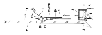
- the jack-up device 19 is configured as a center hole jack, and has a cylindrical jack body 19 a suspended below the suspended-side jack mount 21 and a vertical stroke extending to the jack body 19 a. And a jack-up rod 20 which is held in a possible manner and whose upper end is engaged with the suspension-side jack mount 16 via an equalizer 20a.
- a plurality of jack-up devices 19 having the above-described configuration are installed at predetermined intervals in the tank circumferential direction between the inner and outer tanks 15. After the jackup device 19 is thus installed, the roof mount 10 is removed. When the roof mount 10 is removed, a part or all of the weights of the inner tank roof 14 and the outer tank roof 17 are supported by the plurality of jackup devices 19.
- the inner tank side plate 9 is raised by lifting the knuckle plate 11 with the jack-up device 19. Specifically, when the jack main body 19a is driven to rotate forward, the jack main body 19a rises along the jack-up rod 20 together with the suspended-side jack mount 21, and a tank component member in the middle of assembly (in this embodiment) Jack up the inner tank side plate 9, the knuckle plate 11, the inner tank roof 14 and the outer tank roof 17).
- the knuckle plate 11 lifted by the jack-up device 19 is for connecting the inner tank roof 14 and the inner tank side plate 9 and has a relatively higher strength (thickness) than the inner tank side plate 9. There is no concern about buckling or the like even if the weight including 9 is suspended. That is, the inner tank side plate 9 on the lower stage side is thickened corresponding to the relatively large fluid pressure of the content liquid after completion of the tank, while the inner tank side plate 9 on the upper stage side (especially the uppermost stage) is the inner solution. The plate thickness is reduced to accommodate a relatively small hydraulic pressure.
- the tank constituent member that has been lifted by the jack-up device 19 by one stroke of the jack-up rod 20 (corresponding to the vertical width of the inner tank side plate 9 alone in this embodiment)
- the PC wall 2 is held by 22.
- the work of installing the jack-up device 19 on the top of the PC wall 2 after completion of the PC wall 2 cannot be performed. Therefore, it is necessary to change the position of the suspension-side jack mount 16 serving as a suspension point of the jack-up device 19 as shown in FIGS. 12A and 12B while holding the tank constituent member on the PC wall 2 by the holding means 22. There is.
- the holding means 22 are respectively arranged between the adjacent jackup devices 19.
- the holding means 22 of this embodiment includes a suspended side holding frame 23 provided on the tank component side, a suspended side holding frame 24 provided on the side wall side of the PC wall 2, a suspended side holding frame 23, and a suspended side. And a height adjusting means 25 installed between the holding frame 24.
- the height adjusting means 25 of this embodiment has a screw member 26.
- the suspended side holding base 23 protrudes in a pair substantially horizontally from the knuckle plate 11 toward the inner / outer tank 15.
- the suspended side holding base 23 is detachably fixed to the knuckle plate 11.
- the suspension side holding base 24 protrudes in a pair substantially horizontally from the PC wall 2 having a predetermined height toward the inside of the tank.
- the suspension side holding base 24 is fastened and fixed firmly and detachably to, for example, an anchor plate embedded in the PC wall 2.
- the screw member 26 has a bolt and nut structure, and is installed between the suspended side holding frame 23 and the suspended side holding frame 24.
- the bolt portion of the screw member 26 is disposed so as to be sandwiched between the suspended side holding frame 23 and the suspended side holding frame 24, and the nut part of the screw member 26 is disposed on the suspended side holding frame 23 and the suspended side holding frame 24. It is locked to. Accordingly, the tank constituent member is held so as to be suspended from the PC wall 2.
- the suspension point of the jack-up device 19 is changed as shown in FIGS. 12A and 12B.
- the height adjusting means 25 Prior to this, it is desirable to adjust the holding height of the tank constituent member by the height adjusting means 25. This is because the inclination of the tank constituent member affects the next jackup. Further, if the tank constituent member remains tilted, it affects the mounting of the next inner tank side plate 9 and consequently affects the accuracy of the completed inner tank.
- the holding height of the tank component by the height adjusting means 25 can be adjusted by turning the nut portion of the screw member 26.
- the screw member 26 By using the screw member 26 in this way, the height of the tank constituent member can be adjusted continuously, not stepwise, and the height of the tank constituent member can be adjusted with high accuracy.
- the tank constituent member can be inclined by selectively adjusting the height of the tank constituent member at a plurality of locations on the outer peripheral edge. Can be adjusted arbitrarily.
- the suspension-side jack mount 16 After adjusting the holding height of the tank constituent members, the suspension-side jack mount 16 is released from the PC wall 2 and the jack body 19a is driven in reverse. As a result, as shown in FIGS. 12A and 12B, the jack-up rod 20 and the suspension-side jack mount 16 are raised by one stroke. Thereafter, by using an anchor plate or the like provided at a corresponding position on the PC wall 2, the suspension-side jack mount 16 is removably fixed to the PC wall 2, thereby changing the suspension point of the jack-up device 19. .
- the suspending point of the jack-up device 19 can be easily changed only by raising and detaching the jack-up rod 20 which is relatively lighter than the jack body 19a.
- the holding of the tank constituent member by the holding means 22 is released. Specifically, the screw member 26 is removed, and the suspension side holding frame 24 that the suspended side holding frame 23 interferes during the next jackup is removed from the PC wall 2.
- the holding by the holding means 22 is released, the weight of the tank constituent member is again supported by the plurality of jackup devices 19.
- the next inner tank side plate 9 is carried into the space formed at the lower portion of the inner tank side plate 9 by jacking up as shown in FIG.
- the inner tank side plate 9 is carried in via a construction port (opening) 29 provided in the lower stage of the PC wall 2.
- a transfer device 30 is provided in the construction port 29.
- the transport device 30 includes a rail 31 that extends from the construction port 29 to the outside of the PC wall 2 and a trolley 32 that is movable along the rail 31.
- the rail 31 extends along the tank circumferential direction (tangential direction), and the inner tank side plate 9 carried along the rail 31 between the inner and outer tanks 15 extends in the tank circumferential direction between the inner and outer tanks 15. Is transported to a predetermined position in the circumferential direction of the tank via a second transport device having a rail (both not shown).
- the inner tank side plate 9 is lowered onto the leg-mounted base 8 and is annularly arranged below the jacked up inner tank side plate 9.
- a plurality of inner tank side plates 9 arranged in an annular shape are welded to each other, and the inner tank side plates 9 arranged in the vertical direction are welded together, so that these inner tank side plates 9 are formed into an integral cylindrical shape.
- the inner tank side plates 9 arranged vertically may be welded. In this way, by performing the plurality of inner tank side plates 9 on the outside of the PC wall 2 with less work space restrictions, welding work is facilitated and the inner tank can be assembled efficiently.
- the jackup device 19 is operated as shown in FIGS. 11A and 11B, and the inner tank side plate 9 is moved through the knuckle plate 11 by one stroke. By raising it by an amount, a space for attaching the next inner tank side plate 9 is formed as shown in FIG. Then, the inner tank side plate 9 to be newly attached is carried into the space. In this way, by alternately repeating the raising of the inner tank side plate 9 by the jack-up device 19 and the attachment of the next inner tank side plate 9 to the lower side of the raised inner tank side plate 9, the inner tank side plate 9 Are attached in order from the top to the bottom.
- the cold insulation work of the annular portion 13 and the cold insulation work of the central portion are performed in parallel on the basic version 1.
- the cold insulation work of the annular portion 13 is performed by assembling the pearlite concrete blocks 41A and 41B and the structural lightweight concrete block 42 on the bottom cooling resistance reducing material 39 under the legged base 8. This is done by attaching an annular plate 43 to the plate.
- the annular portion 13 is a member that finally supports the assembled inner tank side plate 9, the annular plate 43 is formed thick, and the cold insulation structure is formed of a hard material such as a concrete block.
- the leg portion 8a of the legged stand 8 disposed on the inner side of the tank with respect to the annular portion 13 is replaced on the annular portion 13 as shown in FIG.
- the leg portion 8a is shortened in consideration of the height of the annular portion 13, and holds the support surface of the leg mount 8 at a constant height with a liner material 27 for height adjustment interposed therebetween.
- the annular portion 13 is formed on the base plate 1 in the space formed under the legged base 8 for supporting the inner tank side plate 9 in this way. Therefore, interference between the assembly work of the inner tank side plate 9 and the cold insulation work in the annular region X can be avoided. Further, in this method, after the annular portion 13 is formed, the leg portion 8 a of the leg mount 8 that is disposed inside the tank with respect to the annular portion 13 is replaced on the annular portion 13. For this reason, it is possible to eliminate interference with the cold insulation work on the base plate 1 in the center portion inside the tank. Therefore, interference between the assembly work of the inner tank side plate 9 and the cold insulation work on the base plate 1 can be avoided, and simultaneous construction of both works becomes possible.
- the PC wall 2 is assembled to the uppermost stage while providing the one-leg scaffold 18. Further, during this process, an elevating staircase 34 is provided outside the PC wall 2. Further, during this process, the outer tank roof 17 is provided with a roof staircase 35, a perlite manhole 36, an inner and outer tank roof manhole 37, and the like.
- the leg-mounted base 8 is removed, and the lower end of the lowest level of the inner tank side plate 9 is lowered onto the annular portion 13.
- the base tank 1 is attached to the inner tank anchor strap 4. Further, the connection between the outer tank roof 17 jacked up together with the inner tank roof 14 and the inner tank roof 14 by the connecting material is released, and the outer tank roof 17 is not attached to the upper end of the PC wall 2 assembled to the top. Attached via the top liner plate shown. On the uppermost PC wall 2, it is desirable to previously install a temporary mount (not shown) for raising the outer tank roof 17 to the mounting height. Thereafter, the leg-mounted base, the jack-up device 19, the suspension side jack base 16, the suspended side jack base 21, and the like are removed.
- reference numeral 1 is a basic version
- reference numeral 7 is a bottom liner
- reference numeral 38 is an inner tank bottom plate
- reference numeral 39 is a bottom cooling resistance reducing material
- reference numeral 40 is bubble glass
- reference numeral 41 is a light-weight bubble.
- Reference numeral 41A and 41B denote pearlite concrete blocks
- reference numeral 42 denotes a lightweight structural concrete block
- reference numeral 43 denotes an annular plate.
- FIG. 18 is an overall flowchart showing the construction method in the embodiment of the present invention.
- hatched processes (foundation, PC wall, side PUF) are processes performed by civil engineering companies.
- the liner (side liner 5) is constructed ahead of the PC wall, and the roof, inner tub and bottom plate are constructed during construction of the PC wall, thereby reducing the construction period. It can be greatly shortened.
- the inner tank side plate 9 is lifted by the jack-up device 19 and the next inner tank side plate 9 to the lower side of the raised inner tank side plate 9 inside the concrete outer tank.
- the construction method of the cylindrical tank 100 having a step of assembling a metal inner tub by alternately repeating the mounting of the pedestal 8 with the legs for supporting the inner tub side plate 9 on the base plate 1
- the step of installing the assembled inner tank so as to straddle the annular area X to be lowered, and the annular portion 13 for supporting the assembled inner tank are formed in the annular area X under the legged base 8.
- FIGS. 19 and 20 For example, a method as shown in FIGS. 19 and 20 may be adopted.
- FIG. 19 and FIG. 20 the same reference numerals are given to the same or equivalent components as those in the above-described embodiment, and the description thereof will be simplified or omitted.
- a suspended holding frame 24 that is a pair of holding means 22 is arranged with a gap through which the suspended holding frame 23 can pass vertically. Then, the holding block B is arranged over the upper surface of the paired suspension side holding frame 24 and the holding member 22 receives the weight of the tank constituent member by engaging the screw member 26 with the holding block B. ing. According to the holding means 22, the suspended side holding frame 23 and the suspended side holding frame 24 do not interfere with each other even when the jack is raised. Therefore, it is not necessary to remove the suspension side holding base 24 before jacking up as in the above embodiment, and the work of changing the suspension point of the jackup device 19 is facilitated.
- a jack-up device 19B for receiving the weight of the tank constituent member is separately provided on the PC wall 2, and the jack-up device 19A and the jack-up device 19B are alternately provided. This is raised while changing the tank components. Further, since the jack-up devices 19A and 19B can adjust the height of the tank constituent member by themselves, it is not necessary to separately provide a height adjusting means such as the screw member 26.
- the assembly work of the uppermost inner tank side plate 9 may be performed after the jack-up work (that is, the knuckle plate 11 is assembled prior to the inner tank side plate 9).
- the inner tank roof 14 and the outer tank roof 17 may be assembled in parallel with the jack-up work.
- the method of raising the jack-up rod 20 and the suspension-side jack mount 16 is not limited to the reverse drive of the jack body 19a, and may be implemented by another lifting device depending on circumstances.
- the replacement of the leg portion 8a of the leg mount 8 can be applied not only to the above-described method of jacking up the knuckle plate 11, but also to the method of directly jacking up the inner tank side plate of the conventional technique. it can.
- the construction method of the cylindrical tank which can aim at shortening of a construction period can be obtained by eliminating interference with the assembly operation of an inner tank, and the cold preservation operation of an outer tank bottom part.
Landscapes
- Engineering & Computer Science (AREA)
- Architecture (AREA)
- General Engineering & Computer Science (AREA)
- Civil Engineering (AREA)
- Structural Engineering (AREA)
- Physics & Mathematics (AREA)
- Thermal Sciences (AREA)
- Mechanical Engineering (AREA)
- Filling Or Discharging Of Gas Storage Vessels (AREA)
Description
本発明は、円筒型タンクの構築方法に関する。
本願は、2012年9月28日に日本に出願された特願2012-215615号に基づき優先権を主張し、その内容をここに援用する。
本願は、2012年9月28日に日本に出願された特願2012-215615号に基づき優先権を主張し、その内容をここに援用する。
内槽と外槽とを有する二重殻構造の円筒型タンクは、LNG(液化天然ガス)やLPG(液化石油ガス)等の低温液体の貯蔵に用いられている。特許文献1には、金属製の内槽とコンクリート製の外槽とを有する円筒型タンクが開示されている。
特許文献1には、円筒型タンクの工期の短縮を図るため、金属製の内槽とコンクリート製の外槽とを同時に施工する手法が開示されている。具体的には、外槽の底部にジャッキ架台を立設させ、ジャッキアップ装置を所定高さに支持させる(特許文献1の図4(b)参照)。そして、外槽の側壁工事を行うときに、外槽の底部上で内槽屋根と外槽屋根とを組み立て、次いで、上記ジャッキアップ装置により内槽屋根と外槽屋根とを上昇させながら、内槽屋根に内槽側板を最上段から下段に向け順々に取り付けることで、金属製の内槽とコンクリート製の外槽とを同時に施工している。
ところで、上記従来技術においては、ジャッキアップ装置によって上昇した内槽側板の下側に取り付けられる次の内槽側板を支持するために、脚付架台を設置している(特許文献1の図8参照)。そして、内槽屋根に最下段の内槽側板を取り付けた後に、脚付架台を撤去し、内槽が下ろされるべきアニュラー領域にパーライトコンクリートブロック及びアニュラープレートを組み立てている(特許文献1の図11参照)。すなわち、上記従来技術では、脚付架台を外槽の底部に設置しているために、外槽の底部に保冷材を敷設する保冷作業がクリティカルパスとなっており、円筒型タンクの工期の短縮を十分に図ることができない。
本発明は、上記問題点に鑑みてなされたものであり、内槽の組み立て作業と外槽底部の保冷作業との干渉をなくして工期の短縮を図ることができる円筒型タンクの構築方法の提供を目的とする。
上記の課題を解決するために、本発明に係る第一の態様は、コンクリート製の外槽の内側において、ジャッキアップ装置による内槽側板の上昇と、前記上昇した内槽側板の下側への次の内槽側板の取り付けと、を交互に繰り返して金属製の内槽を組み立てる工程を有する円筒型タンクの構築方法であって、前記内槽側板を支持するための脚付架台を、前記外槽の底部であって前記組み立てられた内槽が下ろされるべきアニュラー領域を跨ぐように設置する工程と、前記脚付架台の下で、前記アニュラー領域に、前記組み立てられた内槽を支持するためのアニュラー部を形成する工程と、前記アニュラー部の形成後に、前記アニュラー部よりもタンク内側に配置されていた前記脚付架台の脚部を前記アニュラー部の上に挿げ替える工程と、を有する。
本発明に係る第一の態様では、内槽側板を支持するための脚付架台の下に形成された空間において、外槽の底部にアニュラー部を形成する。そして、アニュラー部の形成後、アニュラー部よりもタンク内側に配置されていた脚付架台の脚部をアニュラー部の上に挿げ替えることにより、タンク内側の外槽の底部における保冷作業との干渉をなくすことができる。このため、本発明では、内槽の組立作業と外槽底部の保冷作業との干渉を回避することができる。
本発明に係る第一の態様では、内槽側板を支持するための脚付架台の下に形成された空間において、外槽の底部にアニュラー部を形成する。そして、アニュラー部の形成後、アニュラー部よりもタンク内側に配置されていた脚付架台の脚部をアニュラー部の上に挿げ替えることにより、タンク内側の外槽の底部における保冷作業との干渉をなくすことができる。このため、本発明では、内槽の組立作業と外槽底部の保冷作業との干渉を回避することができる。
また、本発明に係る第二の態様では、前記外槽の側壁に前記ジャッキアップ装置を吊るための吊り点を設けて、タンク屋根部と前記内槽側板とを接続するためのナックル部を前記ジャッキアップ装置により吊り上げることで、前記内槽側板を上昇させる。
本発明に係る第二の態様では、ナックル部を介して内槽側板をジャッキアップする。ナックル部は、タンク屋根部と内槽側板とを接続するためのもので比較的強度(板厚)があるため、内槽側板を含む重量が懸っても座屈等の懸念がない。
本発明に係る第二の態様では、ナックル部を介して内槽側板をジャッキアップする。ナックル部は、タンク屋根部と内槽側板とを接続するためのもので比較的強度(板厚)があるため、内槽側板を含む重量が懸っても座屈等の懸念がない。
また、本発明に係る第三の態様では、前記ジャッキアップ装置の吊り点を順次上方に変更していく工程と、前記吊り点を変更する間、前記ナックル部及び前記内槽側板を含むタンク構成部材を保持手段によって前記外槽の側壁に保持させる工程と、を有する。
本発明に係る第三の態様では、ジャッキアップ装置の吊り点を変更する間、ナックル部及び内槽側板を含むタンク構成部材の重量を保持手段を介して外槽の側壁に受けさせる。これにより、ジャッキアップ装置の次の吊り点への変更が可能となり、ジャッキアップストロークが長い大型のジャッキアップ装置を設置しなくてもナックル部及び内槽側板を含むタンク構成部材の吊り上げが可能となる。
本発明に係る第三の態様では、ジャッキアップ装置の吊り点を変更する間、ナックル部及び内槽側板を含むタンク構成部材の重量を保持手段を介して外槽の側壁に受けさせる。これにより、ジャッキアップ装置の次の吊り点への変更が可能となり、ジャッキアップストロークが長い大型のジャッキアップ装置を設置しなくてもナックル部及び内槽側板を含むタンク構成部材の吊り上げが可能となる。
また、本発明に係る第四の態様では、前記保持手段は、前記タンク構成部材側に設けられた被吊側保持架台と、前記外槽の側壁側に設けられた吊側保持架台と、前記被吊側保持架台と吊側保持架台との間に設置された高さ調節手段と、を有する。
本発明に係る第四の態様では、ジャッキアップ装置の吊り点を変更する間、高さ調節手段を用いて、ナックル部及び内槽側板を含むタンク構成部材の保持手段による保持高さを調節する。これにより、ジャッキアップ装置の次の吊り点への変更にかかる位置調節及び接続作業性の向上を図ることができる。
本発明に係る第四の態様では、ジャッキアップ装置の吊り点を変更する間、高さ調節手段を用いて、ナックル部及び内槽側板を含むタンク構成部材の保持手段による保持高さを調節する。これにより、ジャッキアップ装置の次の吊り点への変更にかかる位置調節及び接続作業性の向上を図ることができる。
また、本発明に係る第五の態様では、前記高さ調節手段が、ネジ部材を有する。
本発明に係る第五の態様では、ネジ部材による連続的な高さ調節を行う。これにより、ナックル部及び内槽側板を含むタンク構成部材の高さ調節を精度よく行うことができる。
本発明に係る第五の態様では、ネジ部材による連続的な高さ調節を行う。これにより、ナックル部及び内槽側板を含むタンク構成部材の高さ調節を精度よく行うことができる。
また、本発明に係る第六の態様では、前記第四または第五の態様において、前記タンク構成部材の外周縁部を、前記保持手段により複数箇所で保持する。
本発明に係る第六の態様では、複数の保持手段により保持したタンク構成部材の外周縁部の複数箇所において選択的に高さ調節を可能とする。これにより、ナックル部及び内槽側板を含むタンク構成部材の傾き調節ができ、内槽の組み立て精度の向上を図ることができる。
本発明に係る第六の態様では、複数の保持手段により保持したタンク構成部材の外周縁部の複数箇所において選択的に高さ調節を可能とする。これにより、ナックル部及び内槽側板を含むタンク構成部材の傾き調節ができ、内槽の組み立て精度の向上を図ることができる。
また、本発明に係る第七の態様では、前記第一~第六の態様のいずれかにおいて、前記内槽側板の取り付けに際し、前記外槽の外側で複数の前記内槽側板を予め横方向に連結し、これを前記外槽の内側に収容して環状に形成したものを、前記上昇した内槽側板の下側に取り付ける。
本発明に係る第七の態様では、複数の内槽側板同士を作業空間の制限の少ないタンク外で行うことができ、効率よく内槽を組み立てることができる。
本発明に係る第七の態様では、複数の内槽側板同士を作業空間の制限の少ないタンク外で行うことができ、効率よく内槽を組み立てることができる。
本発明によれば、内槽の組み立て作業と外槽底部の保冷作業との干渉をなくして工期の短縮を図ることができる円筒型タンクの構築方法が得られる。
以下、本発明の円筒型タンクの構築方法について図面を参照して説明する。以下の説明では、円筒型タンクとして、LNGを貯蔵する地上式のPC(プレストレスコンクリート)二重殻貯槽を例示する。
先ず、図1に示すように、略円板状の基礎版(外槽の底部)1の工事を行う。基礎版1の外周縁部には、後述するPC壁(外槽の側壁)2を組み立てる基礎部3が、上方に突出するよう設置される。また、基礎部3の内側に沿って内槽アンカーストラップ4が設置される。
次に、図2Aに示すように、基礎版1上に側ライナー(外槽側板)5が組み立てられる。なお、側ライナー5は、コンクリート型枠を兼ねている。側ライナー5は、通常板厚が6mm程度の鋼材であるが、本実施形態では板厚を20mm程度もしくは強度を上げた強め材にして、強度を向上させている。
側ライナー5は、基礎部3の内側に沿って組み立てられる。図2Bに示すように、基礎部3の基端部に埋め込みプレート6が設置され、その上に側ライナー5が据え付ける。
また、図2Aに示すように、基礎版1上に底部ライナー7が敷設される。図2Bに示すように、底部ライナー7の縁部は、埋め込みプレート6上に重ねて敷設される。
また、図2Aに示すように、基礎版1上に底部ライナー7が敷設される。図2Bに示すように、底部ライナー7の縁部は、埋め込みプレート6上に重ねて敷設される。
次に、図3に示すように、側ライナー5がさらに組み立てられる。また、側ライナー5の基端部の内側に沿って、内槽側板組立用の脚付架台8が設置される。脚付架台8は、後述する内槽側板9を支持するための門型架台である。この脚付架台8は、内槽側板9が複数組み合わされてなる円筒状の内槽が基礎版1上に最終的に下ろされるべき領域であるアニュラー領域Xを跨ぐように設置される。
次に、図4に示すように、側ライナー5が、最下段から最上段へと順々に組み立てられる。なお、ここでは、側ライナー5が例えば4段目まで組み立てられる。
そして、図5に示すように、先行して4段目まで組み立てられた側ライナー5に沿って、基礎部3上にPC壁2が、最下段から最上段へと順々に、例えば側ライナー5と同数だけ(図では4段目まで)打設して組み立てられる。
そして、図5に示すように、先行して4段目まで組み立てられた側ライナー5に沿って、基礎部3上にPC壁2が、最下段から最上段へと順々に、例えば側ライナー5と同数だけ(図では4段目まで)打設して組み立てられる。
また、脚付架台8上に内槽側板(内槽の側壁でもある)9をタンク周方向に沿って複数立設させ、これら各内槽側板9の隣り合うもの同士を横方向において一体的に溶接することで、これら各内槽側板9が環状に組み立てられる。なお、ここで組み立てる内槽側板9は、最上段(本実施形態では9段目)に対応する。内槽側板9は、優れた靱性と強度を備えるNi鋼材から形成されている。
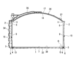
次に、図6に示すように、基礎版1の中央部に屋根架台10が組み立てられる。また、最上段の内槽側板9の上端部にナックルプレート(ナックル部)11が組み付けられる。また、基礎版1上に高所作業車12を乗り入れる。また、脚付架台8の下のアニュラー領域Xにパーライトコンクリートブロックや構造用軽量コンクリートブロック等のアニュラー部13の構成部材が仮置きされる。
次に、図7に示すように、屋根架台10上に内槽屋根ブロックが搭載され、内槽屋根(タンク屋根部)14が組み立てられる。また、内槽屋根14の外周縁部には、ナックルプレート11を介して最上段の内槽側板9が取り付けられる。ナックルプレート11は、内槽屋根14の外周縁部で下方に向けて湾曲するように形成される。このナックルプレート11の下端縁部が最上段の内槽側板9の上端縁部に接続される。
次に、基礎版1よりも上方であって、内外槽間(PC壁2と内槽側板9との間)15において、ナックルプレート11よりも上方のPC壁2に、吊側ジャッキ架台(吊り点)16がタンク周方向に沿って複数設置される。吊側ジャッキ架台16は、所定高さのPC壁2からタンク内方に向けて略水平に突出する。この吊側ジャッキ架台16は、例えばPC壁2に埋め込んだアンカープレート等に強固かつ着脱可能に締結固定される。
また、ナックルプレート11に、複数の吊側ジャッキ架台16に対応する複数の被吊側ジャッキ架台21が設置される。被吊側ジャッキ架台21は、ナックルプレート11から内外槽間15に向けて略水平に突出する。この被吊側ジャッキ架台21がナックルプレート11に着脱可能に固定される。また、ナックルプレート11に被吊側ジャッキ架台21を取り付けることで、被吊側ジャッキ架台21が強度上大型になる場合でも、内外槽間15と比べて、ナックルプレート11の湾曲形状によりPC壁2に対するクリアランスが確保し易くなり、作業を容易に行える。
そして、内槽屋根14を組み立てた後、任意のタイミングで、図8に示すように、内槽屋根14上にて外槽屋根17が組み立てられる。外槽屋根17は、内槽屋根14と不図示の連結材で連結され、内槽屋根14と一体的に組み立てられる。
また、側ライナー5がさらに組み立てられると共に、側ライナー5の外側に片足足場(足場)18を設けて、PC壁2の打設が継続される。PC壁2は、従来のような両足足場ではなく片足足場18とすることができる。このようにすることで、側ライナー5の内側で行われる、後述するジャッキアップ作業との干渉を回避することができる。
次に、図9に示すように、吊側ジャッキ架台16と被吊側ジャッキ架台21との間に渡って、ジャッキアップ装置19が設置される。ジャッキアップ装置19は、図10に示すように、センターホールジャッキとして構成され、被吊側ジャッキ架台21の下方に吊下される円筒状のジャッキ本体19aと、上下に延びてジャッキ本体19aにストローク可能に保持されると共に上端部を吊側ジャッキ架台16にイコライザ20aを介して係合させるジャッキアップロッド20と、を有する。
上記構成のジャッキアップ装置19は、図9に示すように、内外槽間15においてタンク周方向に所定間隔で複数設置される。このようにジャッキアップ装置19が設置された後、屋根架台10が除去される。屋根架台10が除去されると、内槽屋根14及び外槽屋根17の重量の一部又は全部が複数のジャッキアップ装置19によって支持された状態となる。
次に、図11Aに示すように、ジャッキアップ装置19によってナックルプレート11を吊り上げることで、内槽側板9を上昇させる。具体的には、ジャッキ本体19aが正転駆動することで、このジャッキ本体19aが被吊側ジャッキ架台21と共にジャッキアップロッド20を伝うように上昇し、組み立て途中のタンク構成部材(本実施形態では内槽側板9、ナックルプレート11、内槽屋根14及び外槽屋根17を含む)をジャッキアップさせる。
ジャッキアップ装置19によって吊り上げられるナックルプレート11は、内槽屋根14と内槽側板9とを接続するためのもので、内槽側板9よりも比較的強度(板厚)があるため、内槽側板9を含む重量が懸っても座屈等の懸念がない。すなわち、下段側の内槽側板9はタンク完成後における内容液の比較的大きな液圧に対応して板厚を厚くしている一方、上段側(特に最上段)の内槽側板9は内溶液の比較的小さな液圧に対応して板厚を薄くしている。従って、最上段の内槽側板9をジャッキアップ装置19によって直接吊り上げると、下方の内槽側板9を含む重量が懸った際に、最上段の内槽側板9に応力が集中し、最上段の内槽側板9が座屈する懸念がある。しかしながら、本発明では、ジャッキアップ装置19によってナックルプレート11を吊り上げているため、最上段の内槽側板9への応力集中と、それに伴う最上段の内槽側板9の座屈が防止される。このように、内槽側板9の座屈の懸念を無くすことで、上段側の内槽側板9の板厚を不要に厚くする必要がなくなり、内槽側板9の軽量化及びコストダウンを図ることができる。
次に、図11Bに示すように、ジャッキアップ装置19によりジャッキアップロッド20の1ストローク分(本実施形態では内槽側板9単体の上下幅に相当)だけ上昇させたタンク構成部材を、保持手段22によってPC壁2に保持させる。本手法では内外槽の同時施工を行っているため、例えばPC壁2の完成を待ってその頂部にジャッキアップ装置19を設置する等の作業ができない。そこで、タンク構成部材を保持手段22によってPC壁2に保持させている間に、ジャッキアップ装置19の吊り点となる吊側ジャッキ架台16の位置を図12A及び図12Bに示すように変更する必要がある。
保持手段22は、隣り合うジャッキアップ装置19の間にそれぞれ配置される。本実施形態の保持手段22は、タンク構成部材側に設けられた被吊側保持架台23と、PC壁2側壁側に設けられた吊側保持架台24と、被吊側保持架台23と吊側保持架台24との間に設置された高さ調節手段25と、を有する。本実施形態の高さ調節手段25は、ネジ部材26を有する。
被吊側保持架台23は、ナックルプレート11から内外槽間15に向けて略水平に対となって突出する。この被吊側保持架台23はナックルプレート11に着脱可能に固定される。吊側保持架台24は、所定高さのPC壁2からタンク内方に向けて略水平に対となって突出する。この吊側保持架台24は例えばPC壁2に埋め込んだアンカープレート等に強固かつ着脱可能に締結固定される。
ネジ部材26は、ボルトナット構造を有しており、被吊側保持架台23と吊側保持架台24との間に渡って設置される。このネジ部材26のボルト部分は被吊側保持架台23の間及び吊側保持架台24の間に挟むように配置され、ネジ部材26のナット部分は被吊側保持架台23及び吊側保持架台24に係止される。これにより、タンク構成部材がPC壁2に吊下げるようにして保持される。
このようにタンク構成部材がPC壁2に保持されたら、図12A及び図12Bに示すように、ジャッキアップ装置19の吊り点が変更される。なお、この前に、高さ調節手段25によりタンク構成部材の保持高さを調節することが望ましい。タンク構成部材の傾きは、次のジャッキアップに影響するためである。また、タンク構成部材が傾いたままであると、次の内槽側板9の取り付けに影響し、ひいては出来上がった内槽の精度に影響するためである。
高さ調節手段25によるタンク構成部材の保持高さは、ネジ部材26のナット部分を回すことにより調節することができる。このようにネジ部材26を用いることで、段階的でなく連続的にタンク構成部材の高さを調節することができ、タンク構成部材の高さを精度よく調節することができる。また、タンク構成部材の外周縁部は、複数の保持手段22によって保持されているため、外周縁部の複数箇所において選択的にタンク構成部材の高さを調節することにより、タンク構成部材の傾きを任意に調節することができる。このようにタンク構成部材の保持高さを調節することで、ジャッキアップ装置19の次の吊り点への変更に伴う位置調節及び接続作業性の向上を図ることができる。
タンク構成部材の保持高さ調節を行ったら、吊側ジャッキ架台16のPC壁2への固定を解除し、ジャッキ本体19aを逆転駆動させる。これにより、図12A及び図12Bに示すように、ジャッキアップロッド20及び吊側ジャッキ架台16を1ストローク分だけ上昇させる。その後、PC壁2の対応する位置に設けたアンカープレート等を用いることで、吊側ジャッキ架台16をPC壁2に再び着脱可能に固定することにより、ジャッキアップ装置19の吊り点が変更される。
このようにジャッキアップ装置19の逆転駆動によってジャッキアップロッド20を上昇させることにより、ジャッキアップ装置19の吊り点の変更時に、比較的重いジャッキ本体19a側の上昇や着脱が不要となる。このため、ジャッキ本体19aよりも比較的軽いジャッキアップロッド20側の上昇や着脱のみで、ジャッキアップ装置19の吊り点の変更を容易に行うことができる。
ジャッキアップ装置19の吊り点の変更が終わったら、保持手段22によるタンク構成部材の保持が解除される。具体的には、ネジ部材26が取り外され、次のジャッキアップの際に被吊側保持架台23が干渉してしまう吊側保持架台24がPC壁2から除去される。保持手段22による保持が解除されると、タンク構成部材の重量が再び複数のジャッキアップ装置19によって支持された状態となる。
このようなジャッキアップ装置19の吊り点の変更までの間に、図13に示すように、ジャッキアップにより内槽側板9の下部にできた空間に次の内槽側板9が搬入される。内槽側板9の搬入は、PC壁2の下段に設けられた工事口(開口部)29を介して行われる。工事口29には搬送装置30が設けられる。搬送装置30は、工事口29からPC壁2の外側に延びるレール31と、レール31に沿って移動自在なトロリー32とを有する。
レール31は、タンク周方向(接線方向)に沿うように延び、このレール31に沿って内外槽間15に搬入された内槽側板9は、内外槽間15でタンク周方向に沿って延びる環状のレールを有する第2搬送装置(何れも不図示)を介して、タンク周方向で所定位置に搬送される。この内槽側板9は脚付架台8上に降ろされ、ジャッキアップされた内槽側板9の下方に環状に配置される。
次に、環状に配置した複数の内槽側板9同士を溶接し、かつ上下に並ぶ内槽側板9同士を溶接することで、これら内槽側板9が一体の円筒状に形成される。なお、複数の内槽側板9同士がタンク外で予め横方向に連結され、これが内外槽間15に収容され環状に形成された後、上下に並ぶ内槽側板9同士が溶接されてもよい。このように複数の内槽側板9同士を作業空間の制限の少ないPC壁2の外側で行うことで、溶接作業が容易になり、効率よく内槽を組み立てることができる。
内槽側板9の取り付け後、ジャッキアップ装置19の吊り点の変更が終わったら、図11A及び図11Bに示す如くジャッキアップ装置19を作動させ、ナックルプレート11を介して内槽側板9を1ストローク分だけ上昇させることにより、図13に示す如く次の内槽側板9を取り付けるための空間が形成される。そして、その空間に、また新たに取り付けるべき内槽側板9が搬入される。このようにして、ジャッキアップ装置19による内槽側板9の上昇と、上昇した内槽側板9の下側への次の内槽側板9の取り付けとを、交互に繰り返すことにより、内槽側板9が最上段のものから最下段のものまで順々に取り付けられる。
ところで、これらの工程中、基礎版1上で、アニュラー部13の保冷工事及び中央部の保冷工事が並行して行われる。アニュラー部13の保冷工事は、図10に示すように、脚付架台8の下で、底部冷熱抵抗緩和材39の上にパーライトコンクリートブロック41A,41B、構造用軽量コンクリートブロック42を組み立て、その上にアニュラープレート43を取り付けることにより行われる。アニュラー部13は、組み立てられた内槽側板9を最終的に支持する部材で、アニュラープレート43が厚く形成され、またその保冷構造もコンクリートブロック等の硬質なもので形成される。
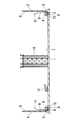
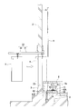
アニュラー部13の保冷工事が終わったら、アニュラー部13よりもタンク内側に配置されていた脚付架台8の脚部8aが図13に示すようにアニュラー部13の上に挿げ替えられる。脚部8aはアニュラー部13の高さを考慮して短縮され、高さ調節のためのライナー材27を間に挟んで、脚付架台8の支持面を一定高さに保持する。このような挿げ替えによって、アニュラー部13よりもタンク内側には干渉物がなくなるため、図14に示すように、基礎版1上の中央部に保冷材33を敷設する保冷工事を行うことができる。
本手法では、このように内槽側板9を支持するための脚付架台8の下に形成された空間において、基礎版1上にアニュラー部13が形成される。そのため、内槽側板9の組み付け作業とアニュラー領域Xにおける保冷作業との干渉を回避することができる。また、本手法では、アニュラー部13の形成後、アニュラー部13よりもタンク内側に配置されていた脚付架台8の脚部8aがアニュラー部13の上に挿げ替えられる。そのため、タンク内側中央部の基礎版1上における保冷作業との干渉をなくすことができる。したがって、内槽側板9の組立作業と基礎版1上の保冷作業との干渉を回避し、両作業の同時施工が可能となる。
なお、この工程中、図14に示すように、片足足場18を設けつつ、PC壁2が最上段まで組み立てられる。また、この工程中、昇降階段34がPC壁2の外部に設けられる。また、この工程中、外槽屋根17に、屋根階段35、パーライトマンホール36や内外槽屋根マンホール37等が設けられる。
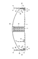
次に、図15に示すように、内槽側板9の最下段までの取り付けが終了したら、脚付架台8が撤去され、内槽側板9の最下段の下端部がアニュラー部13上に降ろされ、基礎版1に設置された内槽アンカーストラップ4に取り付けられる。また、内槽屋根14と共にジャッキアップされた外槽屋根17と内槽屋根14との連結材による連結が解除され、外槽屋根17が、最上段まで組み立てられたPC壁2の上端部に不図示の頂部ライナープレートを介して取り付けられる。
最上段のPC壁2上には、外槽屋根17を取り付け高さまで上昇させるための仮架台(不図示)を予め設置しておくことが望ましい。その後、脚付架台、ジャッキアップ装置19、吊側ジャッキ架台16及び被吊側ジャッキ架台21等が撤去される。
最上段のPC壁2上には、外槽屋根17を取り付け高さまで上昇させるための仮架台(不図示)を予め設置しておくことが望ましい。その後、脚付架台、ジャッキアップ装置19、吊側ジャッキ架台16及び被吊側ジャッキ架台21等が撤去される。
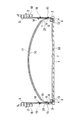
また、上記工程中に、図16Aに示すように、内槽底板38が敷設される。これにより、底部の保冷工事が終了する。なお、図16Bにおいて、符号1は基礎版を、符号7は底部ライナーを、符号38は内槽底板を、符号39は底部冷熱抵抗緩和材を、符号40はあわガラスを、符号41は軽量気泡コンクリートを、符号41A及び41Bはパーライトコンクリートブロックを、符号42は構造用軽量コンクリートブロックを、符号43はアニュラープレートをそれぞれ示す。
その後、PC壁2の緊張工事が行われる。そして、不図示の内槽工事口の閉鎖、不図示のポンプバレルの設置を経た後、水張りをして、耐圧・気密試験が実施される。
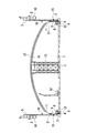
最後に、図17に示すように、内外槽間15に保冷材44(例えばパーライト)が充填されて内外槽間保冷工事が行われ、その後、塗装工事、配管保冷工事を経て円筒型タンク100が構築される。
最後に、図17に示すように、内外槽間15に保冷材44(例えばパーライト)が充填されて内外槽間保冷工事が行われ、その後、塗装工事、配管保冷工事を経て円筒型タンク100が構築される。
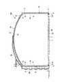
図18は、本発明の実施形態における構築方法を示す全体のフロー図である。なお、図18において、ハッチを付した工程(基礎、PC壁、側PUF)は、土木事業者による工程である。本図に示すように、基礎を工事した後、ライナー(側ライナー5)をPC壁よりも先行して工事し、かつPC壁構築中に屋根、内槽及び底板を工事することで、工期を大幅に短縮することができる。
このように、上述の本実施形態では、コンクリート製の外槽の内側において、ジャッキアップ装置19による内槽側板9の上昇と、上昇した内槽側板9の下側への次の内槽側板9の取り付けと、を交互に繰り返して金属製の内槽を組み立てる工程を有する円筒型タンク100の構築方法において、内槽側板9を支持するための脚付架台8を、基礎版1上であって組み立てられた内槽が下ろされるべきアニュラー領域Xを跨ぐように設置する工程と、脚付架台8の下で、アニュラー領域Xに、組み立てられた内槽を支持するためのアニュラー部13を形成する工程と、アニュラー部13の形成後に、アニュラー部13よりもタンク内側に配置されていた脚付架台8の脚部8aをアニュラー部13の上に挿げ替える工程と、を有する。この手法を採用することによって、基礎版1に保冷材を敷設する保冷作業がクリティカルパスとならなくなる。そのため、内槽の組み立て作業と基礎版1の保冷作業との干渉をなくして工期の短縮化を図ることができる。
以上、図面を参照しながら本発明の好適な実施形態について説明したが、本発明は上記実施形態に限定されるものではない。上述した実施形態において示した各構成部材の諸形状や組み合わせ等は一例であって、本発明の主旨から逸脱しない範囲において設計要求等に基づき種々変更可能である。
例えば、図19及び図20に示すような手法を採用してもよい。なお、図19及び図20においては、上述の実施形態と同一又は同等の構成部分については同一の符号を付し、その説明を簡略若しくは省略する。
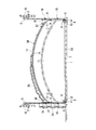
図19に示す別実施形態において、保持手段22の対となった吊側保持架台24には、被吊側保持架台23が上下に通過可能な隙間を開けて配置されている。そして、この対となった吊側保持架台24の上面に渡って保持ブロックBを配置し、この保持ブロックBにネジ部材26を係合させることで、保持手段22がタンク構成部材の重量を受けている。この保持手段22によれば、ジャッキアップによっても被吊側保持架台23と吊側保持架台24とが干渉しなくなる。そのため、上記実施形態のようにジャッキアップの前に吊側保持架台24を除去する必要がなくなり、ジャッキアップ装置19の吊り点の変更作業が容易になる。
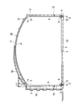
また、図20に示す別実施形態においては、保持手段22に代わり、PC壁2にタンク構成部材の重量を受けるジャッキアップ装置19Bを別途設け、ジャッキアップ装置19Aとジャッキアップ装置19Bとで交互にタンク構成部材を持ち替えつつこれを上昇させている。また、ジャッキアップ装置19A,19Bは、それ自体でタンク構成部材の高さの調節が可能であるため、ネジ部材26のような高さ調節手段を別途設けなくてもよい。
また、例えば、最上段の内槽側板9の組み付け作業は、ジャッキアップ作業の後に(すなわち、内槽側板9に先行してナックルプレート11を組み立てるように)行ってもよい。
また、例えば、内槽屋根14,外槽屋根17の組み立てをジャッキアップ作業と並行して行ってもよい。
また、例えば、ジャッキアップロッド20及び吊側ジャッキ架台16を上昇させる手法は、ジャッキ本体19aの逆転駆動に限定されず、場合によっては別の吊り上げ装置で実施してもよい。
また、例えば、上記の実施形態では、ジャッキアップ装置19の1ストローク毎に内槽側板9の組み付け作業を行うと説明されているが、ジャッキアップ装置19の1ストローク中に複数の内槽側板9の組み付け作業を行ってもよい。
また、例えば、脚付架台8の脚部8aの挿げ替えは、上述したナックルプレート11をジャッキアップさせる手法だけでなく、従来技術の内槽側板を直接ジャッキアップさせる手法にも適用することができる。
本発明によれば、内槽の組み立て作業と外槽底部の保冷作業との干渉をなくして工期の短縮を図ることができる円筒型タンクの構築方法が得られる。
1…基礎版(外槽の底部)
2…PC壁(外槽の側壁)
8…脚付架台
8a…脚部
9…内槽側板
11…ナックルプレート(ナックル部)
13…アニュラー部
14…内槽屋根(タンク屋根部)
16…ジャッキ用架台(架台)
19…ジャッキアップ装置
22…保持手段
23…被吊側保持架台
24…吊側保持架台
25…高さ調節手段
26…ネジ部材
100…円筒型タンク
X…アニュラー領域
2…PC壁(外槽の側壁)
8…脚付架台
8a…脚部
9…内槽側板
11…ナックルプレート(ナックル部)
13…アニュラー部
14…内槽屋根(タンク屋根部)
16…ジャッキ用架台(架台)
19…ジャッキアップ装置
22…保持手段
23…被吊側保持架台
24…吊側保持架台
25…高さ調節手段
26…ネジ部材
100…円筒型タンク
X…アニュラー領域
Claims (7)
- コンクリート製の外槽の内側において、ジャッキアップ装置による内槽側板の上昇と、前記上昇した内槽側板の下側への次の内槽側板の取り付けと、を交互に繰り返して金属製の内槽を組み立てる工程を有する円筒型タンクの構築方法であって、
前記内槽側板を支持するための脚付架台を、前記外槽の底部であって前記組み立てられた内槽が下ろされるべきアニュラー領域を跨ぐように設置する工程と、
前記脚付架台の下で、前記アニュラー領域に、前記組み立てられた内槽を支持するためのアニュラー部を形成する工程と、
前記アニュラー部の形成後に、前記アニュラー部よりもタンク内側に配置されていた前記脚付架台の脚部を前記アニュラー部の上に挿げ替える工程と、を有する、円筒型タンクの構築方法。 - 前記外槽の側壁に前記ジャッキアップ装置を吊るための吊り点を設けて、タンク屋根部と前記内槽側板とを接続するためのナックル部を前記ジャッキアップ装置により吊り上げることで、前記内槽側板を上昇させる、請求項1に記載の円筒型タンクの構築方法。
- 前記ジャッキアップ装置の吊り点を順次上方に変更していく工程と、
前記吊り点を変更する間、前記ナックル部及び前記内槽側板を含むタンク構成部材を保持手段によって前記外槽の側壁に保持させる工程と、を有する、請求項2に記載の円筒型タンクの構築方法。 - 前記保持手段は、
前記タンク構成部材側に設けられた被吊側保持架台と、
前記外槽の側壁側に設けられた吊側保持架台と、
前記被吊側保持架台と吊側保持架台との間に設置された高さ調節手段と、を有する、請求項3に記載の円筒型タンクの構築方法。 - 前記高さ調節手段は、ネジ部材を有する、請求項4に記載の円筒型タンクの構築方法。
- 前記タンク構成部材の外周縁部を、前記保持手段により複数箇所で保持する、請求項4または5に記載の円筒型タンクの構築方法。
- 前記内槽側板の取り付けにおいては、前記外槽の外側で複数の前記内槽側板を予め横方向に連結し、これを前記外槽の内側に収容して環状に形成したものを、前記上昇した内槽側板の下側に取り付ける、請求項1~6のいずれか一項に記載の円筒型タンクの構築方法。
Priority Applications (1)
| Application Number | Priority Date | Filing Date | Title |
|---|---|---|---|
| PH12015500402A PH12015500402A1 (en) | 2012-09-28 | 2015-02-24 | Method for constructing cylindrical tank |
Applications Claiming Priority (2)
| Application Number | Priority Date | Filing Date | Title |
|---|---|---|---|
| JP2012215615A JP6018865B2 (ja) | 2012-09-28 | 2012-09-28 | 円筒型タンクの構築方法 |
| JP2012-215615 | 2012-09-28 |
Publications (1)
| Publication Number | Publication Date |
|---|---|
| WO2014050231A1 true WO2014050231A1 (ja) | 2014-04-03 |
Family
ID=50387648
Family Applications (1)
| Application Number | Title | Priority Date | Filing Date |
|---|---|---|---|
| PCT/JP2013/067190 Ceased WO2014050231A1 (ja) | 2012-09-28 | 2013-06-24 | 円筒型タンクの構築方法 |
Country Status (4)
| Country | Link |
|---|---|
| JP (1) | JP6018865B2 (ja) |
| PH (1) | PH12015500402A1 (ja) |
| TW (1) | TWI597410B (ja) |
| WO (1) | WO2014050231A1 (ja) |
Families Citing this family (3)
| Publication number | Priority date | Publication date | Assignee | Title |
|---|---|---|---|---|
| JP6351174B2 (ja) * | 2014-11-19 | 2018-07-04 | 株式会社Ihi | 円筒型タンクの構築方法 |
| JP6366184B2 (ja) * | 2014-11-19 | 2018-08-01 | 株式会社Ihi | 円筒型タンクの構築方法 |
| JP6465488B2 (ja) * | 2015-09-11 | 2019-02-06 | 株式会社Ihi | 円筒型タンクの構築方法 |
Citations (2)
| Publication number | Priority date | Publication date | Assignee | Title |
|---|---|---|---|---|
| JPH07253196A (ja) * | 1994-03-14 | 1995-10-03 | Mitsubishi Heavy Ind Ltd | コンクリート外槽低温タンクの建設工法 |
| JP2012149416A (ja) * | 2011-01-18 | 2012-08-09 | Ihi Corp | 円筒型タンクの構築方法 |
Family Cites Families (3)
| Publication number | Priority date | Publication date | Assignee | Title |
|---|---|---|---|---|
| JPH0762924A (ja) * | 1993-08-23 | 1995-03-07 | Mitsubishi Heavy Ind Ltd | コンクリート外槽低温タンクの建設工法 |
| TW324763B (en) * | 1997-01-30 | 1998-01-11 | Kvaerner Rj Brown Pte Ltd | Bottom structure design for coastal towers |
| TW200925370A (en) * | 2007-10-26 | 2009-06-16 | John Clement Preston | Safety barriers |
-
2012
- 2012-09-28 JP JP2012215615A patent/JP6018865B2/ja not_active Expired - Fee Related
-
2013
- 2013-06-24 TW TW102122349A patent/TWI597410B/zh not_active IP Right Cessation
- 2013-06-24 WO PCT/JP2013/067190 patent/WO2014050231A1/ja not_active Ceased
-
2015
- 2015-02-24 PH PH12015500402A patent/PH12015500402A1/en unknown
Patent Citations (2)
| Publication number | Priority date | Publication date | Assignee | Title |
|---|---|---|---|---|
| JPH07253196A (ja) * | 1994-03-14 | 1995-10-03 | Mitsubishi Heavy Ind Ltd | コンクリート外槽低温タンクの建設工法 |
| JP2012149416A (ja) * | 2011-01-18 | 2012-08-09 | Ihi Corp | 円筒型タンクの構築方法 |
Also Published As
| Publication number | Publication date |
|---|---|
| TWI597410B (zh) | 2017-09-01 |
| TW201413094A (zh) | 2014-04-01 |
| JP6018865B2 (ja) | 2016-11-02 |
| JP2014070359A (ja) | 2014-04-21 |
| PH12015500402A1 (en) | 2015-04-27 |
Similar Documents
| Publication | Publication Date | Title |
|---|---|---|
| JP5732527B2 (ja) | 円筒型タンクの構築方法 | |
| JP6127453B2 (ja) | 円筒型タンクの構築方法 | |
| JP5732262B2 (ja) | 円筒型タンクの構築方法 | |
| JP6127459B2 (ja) | 円筒型タンクの構築方法 | |
| JP6202729B2 (ja) | 円筒型タンクの構築方法 | |
| JP6483410B2 (ja) | 円筒型タンクの構築方法 | |
| JP6018865B2 (ja) | 円筒型タンクの構築方法 | |
| JP6106539B2 (ja) | 円筒型タンクの構築方法 | |
| JP6448024B2 (ja) | ジャッキアップシステムの同調方法及び円筒型タンクの構築方法 | |
| TWI502119B (zh) | 圓筒型儲槽之構築方法 | |
| WO2014208672A1 (ja) | 円筒型タンクの構築方法 | |
| JP2018059300A (ja) | タンクの構築方法 | |
| WO2014208705A1 (ja) | 円筒型タンクの構築方法 | |
| WO2017043622A1 (ja) | 円筒型タンクの構築方法 | |
| TW201404991A (zh) | 圓筒型儲槽之構築方法 | |
| JP2015010358A (ja) | 円筒型タンクの構築方法 | |
| JP2019078051A (ja) | タンク及びタンクの構築方法 | |
| JP6461758B2 (ja) | 円筒型タンクの構築方法 | |
| JP2020084607A (ja) | タンクの構築方法 | |
| WO2016080455A1 (ja) | 円筒型タンクの構築方法 | |
| JP2018053430A (ja) | 頂部サポート | |
| JP2019082106A (ja) | 円筒型タンクの構築方法 | |
| JP2019007151A (ja) | 頂部サポート、頂部サポートシステム及びタンクの構築方法 | |
| JP2016098511A (ja) | 円筒型タンクの構築方法 | |
| JP2016098509A (ja) | 円筒型タンクの構築方法 |
Legal Events
| Date | Code | Title | Description |
|---|---|---|---|
| 121 | Ep: the epo has been informed by wipo that ep was designated in this application |
Ref document number: 13840874 Country of ref document: EP Kind code of ref document: A1 |
|
| WWE | Wipo information: entry into national phase |
Ref document number: 12015500402 Country of ref document: PH |
|
| NENP | Non-entry into the national phase |
Ref country code: DE |
|
| 122 | Ep: pct application non-entry in european phase |
Ref document number: 13840874 Country of ref document: EP Kind code of ref document: A1 |