WO2014046292A1 - Méthode de soins et robot de soins - Google Patents
Méthode de soins et robot de soins Download PDFInfo
- Publication number
- WO2014046292A1 WO2014046292A1 PCT/JP2013/075960 JP2013075960W WO2014046292A1 WO 2014046292 A1 WO2014046292 A1 WO 2014046292A1 JP 2013075960 W JP2013075960 W JP 2013075960W WO 2014046292 A1 WO2014046292 A1 WO 2014046292A1
- Authority
- WO
- WIPO (PCT)
- Prior art keywords
- shaft
- robot
- care
- arm
- control unit
- Prior art date
- Legal status (The legal status is an assumption and is not a legal conclusion. Google has not performed a legal analysis and makes no representation as to the accuracy of the status listed.)
- Ceased
Links
Images


Classifications
-
- A—HUMAN NECESSITIES
- A61—MEDICAL OR VETERINARY SCIENCE; HYGIENE
- A61G—TRANSPORT, PERSONAL CONVEYANCES, OR ACCOMMODATION SPECIALLY ADAPTED FOR PATIENTS OR DISABLED PERSONS; OPERATING TABLES OR CHAIRS; CHAIRS FOR DENTISTRY; FUNERAL DEVICES
- A61G7/00—Beds specially adapted for nursing; Devices for lifting patients or disabled persons
- A61G7/10—Devices for lifting patients or disabled persons, e.g. special adaptations of hoists thereto
- A61G7/104—Devices carried or supported by
- A61G7/1046—Mobile bases, e.g. having wheels
-
- A—HUMAN NECESSITIES
- A61—MEDICAL OR VETERINARY SCIENCE; HYGIENE
- A61G—TRANSPORT, PERSONAL CONVEYANCES, OR ACCOMMODATION SPECIALLY ADAPTED FOR PATIENTS OR DISABLED PERSONS; OPERATING TABLES OR CHAIRS; CHAIRS FOR DENTISTRY; FUNERAL DEVICES
- A61G7/00—Beds specially adapted for nursing; Devices for lifting patients or disabled persons
- A61G7/10—Devices for lifting patients or disabled persons, e.g. special adaptations of hoists thereto
- A61G7/1013—Lifting of patients by
- A61G7/1019—Vertical extending columns or mechanisms
-
- A—HUMAN NECESSITIES
- A61—MEDICAL OR VETERINARY SCIENCE; HYGIENE
- A61G—TRANSPORT, PERSONAL CONVEYANCES, OR ACCOMMODATION SPECIALLY ADAPTED FOR PATIENTS OR DISABLED PERSONS; OPERATING TABLES OR CHAIRS; CHAIRS FOR DENTISTRY; FUNERAL DEVICES
- A61G7/00—Beds specially adapted for nursing; Devices for lifting patients or disabled persons
- A61G7/10—Devices for lifting patients or disabled persons, e.g. special adaptations of hoists thereto
- A61G7/1025—Lateral movement of patients, e.g. horizontal transfer
- A61G7/1036—Lateral movement of patients, e.g. horizontal transfer facilitating loading and unloading of the patient, e.g. using flaps or additional tilting
-
- A—HUMAN NECESSITIES
- A61—MEDICAL OR VETERINARY SCIENCE; HYGIENE
- A61G—TRANSPORT, PERSONAL CONVEYANCES, OR ACCOMMODATION SPECIALLY ADAPTED FOR PATIENTS OR DISABLED PERSONS; OPERATING TABLES OR CHAIRS; CHAIRS FOR DENTISTRY; FUNERAL DEVICES
- A61G7/00—Beds specially adapted for nursing; Devices for lifting patients or disabled persons
- A61G7/10—Devices for lifting patients or disabled persons, e.g. special adaptations of hoists thereto
- A61G7/1049—Attachment, suspending or supporting means for patients
- A61G7/1057—Supported platforms, frames or sheets for patient in lying position
-
- A—HUMAN NECESSITIES
- A61—MEDICAL OR VETERINARY SCIENCE; HYGIENE
- A61G—TRANSPORT, PERSONAL CONVEYANCES, OR ACCOMMODATION SPECIALLY ADAPTED FOR PATIENTS OR DISABLED PERSONS; OPERATING TABLES OR CHAIRS; CHAIRS FOR DENTISTRY; FUNERAL DEVICES
- A61G2203/00—General characteristics of devices
- A61G2203/10—General characteristics of devices characterised by specific control means, e.g. for adjustment or steering
- A61G2203/22—General characteristics of devices characterised by specific control means, e.g. for adjustment or steering for automatically guiding movable devices, e.g. stretchers or wheelchairs in a hospital
Definitions
- the present invention relates to a care method and a care robot used therefor. More specifically, the present invention relates to a care method capable of reducing the burden on a caregiver and a care recipient and a care robot used therefor.
- caregivers such as care helpers have been supporting the lives of elderly people and persons with disabilities (hereinafter referred to as care recipients).
- care recipients In life support by a caregiver such as a care helper of a care recipient, the transfer from the bed to the wheelchair or the transfer from the wheelchair to the bed is performed when the care recipient needs assistance in the toilet or bathing.
- a caregiver such as a single care helper, and this results in a great burden on the caregiver such as a care helper.
- many caregivers such as care helpers hurt their backs.
- Low back pain has been referred to as an occupational disease of caregivers such as care helpers.
- the present invention has been made in view of the problems of the prior art, and it is an object of the present invention to provide a care method and a care robot that can simplify and reduce the burden on a caregiver such as a care helper, in particular, the burden on transfer. It is said.
- the care method of the present invention includes a procedure for laying a sheet in which a held portion to be held by a robot arm is formed on both ends on a bed, a procedure for putting a care recipient on the sheet, a robot, and a robot arm Positioning the robot relative to the care recipient, moving the robot forward toward the bed and holding the held portion by the arm, raising the arm by a predetermined amount, and And a step of retracting the robot from the bed in a state where the robot is raised by a predetermined amount.
- a procedure for increasing the height of the held portion on the head side of the care recipient to be higher than the height of the held portion on the foot side is preferably added.
- the first form of the nursing robot according to the present invention includes a base portion that can travel, first and second lifting shafts disposed on the base portion, and a U-shaped member.
- a rotating member that holds the bottom of the U-shaped member in a rotatable and non-slidable manner, and the second elevating shaft rotates the bottom of the U-shaped member in a rotatable and slidable manner;
- a movable member wherein the bottom portion is rotatably and slidably held by the rotating member of the first elevating shaft, and is rotatable and slidable by the rotating member of the second elevating shaft. It is characterized by being held.
- a care robot includes a base that is capable of traveling, a lifting shaft that is disposed on the base, a pivot that is disposed on the lifting shaft, and an axisymmetric arrangement with respect to the pivot.
- a first telescopic shaft and a second telescopic shaft provided, a first arm disposed on the first telescopic shaft, and a second arm disposed on the second telescopic shaft.
- an operation panel is provided, the operation panel has a manual operation means and a control unit, and the control unit is a position force for switching control between position control and force control.
- the second telescopic shaft drive control means for controlling the driving of the second telescopic shaft is preferably included.
- the operation panel has a robot operation button added thereto
- the control unit has a position force control switching means for switching control between position control and force control, and a lift axis drive control means for controlling the drive of the lift axis.
- a swing axis drive control means for controlling the drive of the swing axis, a first extendable axis drive control means for controlling the drive of the first extendable axis, and a second extendable axis drive control means for controlling the drive of the second extendable axis. It is more preferable that the control unit is capable of operating each means in response to a signal from the robot operation button.
- a head side indicating means for indicating whether the position of the head of the caregiver is on the right side or the left side of the care robot is added, and the turning axis drive control means is provided with a turning angle limiter. And the turning angle limiting portion is provided by the head side indicating means. It is further preferable to limit the turning angle so that the head of the care recipient is not positioned below the horizontal in response to the number, or the operation panel is provided with manual automatic switching means and operation pattern selection means. It is further preferable that the control unit includes an operation pattern holding unit. Moreover, in the 2nd form of the care robot of this invention, it is preferable that a 1st arm and a 2nd arm are made into the rod shape.
- the base has a running part
- the running part has a front wheel support member
- the front wheel support member has a rear slope with a front horizontal part and an upward slope. It is preferable to have a part.
- the present invention is configured as described above, when the care recipient is transferred from the bed to a wheelchair or the like, it is not necessary for the caregiver to lift the care recipient from the bed, thereby reducing the burden on the caregiver. There is an excellent effect.
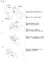
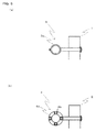
- FIG. 1 is a schematic view showing a care procedure according to the care method of the present invention.
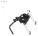
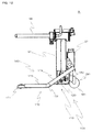
- FIG. 2 is a perspective view of the care robot according to Embodiment 1 of the present invention.
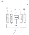
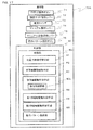
- FIG. 3 is a block diagram of the robot.
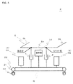
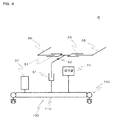
- FIG. 4 is a schematic view of the robot.
- FIG. 5 is a schematic view of an example of a U-shaped member holding portion, in which FIG. 5A shows a fixed portion and FIG. 5B shows a slide portion.
- FIG. 6 is a block diagram of the operation panel.
- FIG. 7 is a two-side view of the dedicated sheet.
- FIG. 8 is a schematic cross-sectional view of a modified example of the held portion of the dedicated sheet.
- FIG. 9 is a skeleton diagram of a care robot according to Embodiment 2 of the present invention.
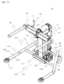
- FIG. 10 is a perspective view of the robot.
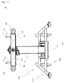
- FIG. 11 is a plan view of the robot.
- FIG. 12 is a right side view of the robot.
- FIG. 13 is a rear view of the robot.
- FIG. 14 is a plan view of the robot.
- FIG. 15 is a block diagram of the operation panel.
- FIG. 16 is a block diagram of the operation lever.
- FIG. 17 is a block diagram of an operation panel of a nursing robot according to Embodiment 3 of the present invention.
- FIG. 18 is a schematic view of a state in which two nursing robots equipped with makeup covers are automatically operated to face each other.
- the care method of the present invention supports the transfer of a care recipient who is sleeping on a bed to a wheelchair or the like by a care robot according to the following procedure. That is, transfer to a wheelchair or the like is performed by a transfer support robot (care robot). The following operations are performed by a caregiver.
- Step 1 The care recipient who is sleeping on the bed is changed the position on the bed in the opposite direction to the entrance side of the transfer support robot (hereinafter simply referred to as the robot), that is, the entire body is half-raised. A special sheet is placed near the end (see FIG. 1A).
- Step 2 Return the position of the care recipient to the original position and place the care recipient in the dedicated sheet, and then advance the robot to enter the bed and hold the dedicated sheet with the arm (arm) (FIG. 1 (b) )reference).
- Step 3 Lift the special sheet. That is, the care recipient is lifted from the bed (see FIG. 1C).
- Procedure 4 The robot is moved backward to move the care recipient to the side of the bed (see FIG. 1 (d)). By doing so, the burden on the caregiver such as a care helper when the care recipient is transferred from the bed to a wheelchair or the like is reduced.
- Embodiment 1 As shown in FIGS.
- the robot R has a base B that is allowed to run in the front-rear direction, a first lifting shaft 1 that is erected on the base B, and a first lifting shaft 1 that is fixed to the base B.
- the second elevating shaft 2 erected with an interval of, the main rotating member 3 mounted on the upper end portion of the first elevating shaft 1, and the follower rotating mounted on the upper end portion of the second elevating shaft 2
- Main components are a member 4, a U-shaped member 5 that is slidably attached to the main rotating member 3 and slidably attached to the sub-rotating member 4, a driving power source 6, and an operation panel 10. It is supposed to be prepared as an element. As shown in FIG. 2 and FIG.
- the base B has travel members 20 mounted in parallel at both ends, and can travel in the front-rear direction by the travel members 20.
- the traveling member 20 is configured such that traveling wheels 22 are attached to both ends of a pipe 21 with caps attached to both ends.
- the traveling wheel 22 may be mounted on the pipe 21 so as to be turnable. By doing so, the robot R can run not only forward and backward but also left and right.
- shaft 2 shall consist of an electric cylinder, for example.
- the U-shaped member 5 includes a bottom portion 5a and an arm 5b protruding from the bottom portion 5a, and the bottom portion 5a is held by the main rotating member 3 and the sub-rotating member 4 as described above. Further, the distance between the arms 5b and 5b is made to coincide with the distance between the held parts 31 (see FIG. 7) provided at the end of the dedicated sheet 30.
- FIG. 5 shows an example of the fixed portion and the slide portion. In the fixed portion, the bottom portion 5a is gripped by the grip portion 3a of the main rotating member 3 attached to the upper end portion of the first elevating shaft 1, as shown in FIG. On the other hand, in the slide portion, as shown in FIG.
- the driving power source 6 is, for example, a battery, which makes the robot R so-called cordless.
- the driving power source 6 includes a first driving power source 6A for driving the first lifting shaft 1 and a second driving power source 6B for driving the second lifting shaft 2.
- the first lifting shaft 1 And the first driving power source 6A are electrically connected, and the second lifting shaft 2 and the second driving power source 6B are electrically connected. As shown in FIG.
- the operation panel 10 includes a first drive power switch 11 that turns on and off the first drive power supply 6A, a second drive power switch 12 that turns on and off the second drive power supply 6B, A first raising button 13 that raises the lifting shaft 1, a first lowering button 14 that lowers the first lifting shaft 1, a second lifting button 15 that raises the second lifting shaft 2, and a second lifting shaft And a second lowering button 16 for lowering 2.
- the operation panel 10 is disposed, for example, behind an intermediate portion between the first lifting shaft 1 and the second lifting shaft 2.
- FIG. 7 shows an example of the dedicated sheet 30. As shown in FIG. 7, the dedicated sheet 30 has cylindrical held portions 31 into which the arms 5 b of the robot R are inserted at both ends.
- the held portion 31 includes a base material 32, a cushion layer 33 made of a cushioning material disposed outside the base material 32, and a surface layer 34 made of a synthetic resin sheet.
- Procedure 11 The robot R is moved as appropriate, and the arms 5b and 5b of the U-shaped member 5 are aligned with the positions of the held portions 31 provided at both ends of the dedicated sheet 30. In this case, the robot R is positioned so that the first lifting shaft 1 is close to the head of the care recipient.
- Step 12 The buttons on the operation panel 10 are appropriately pressed so that the arms 5b and 5b of the U-shaped member 5 are held at both ends of the dedicated sheet 30 where the care recipient needs to lie down.
- Procedure 13 The robot R is advanced and both arms 5b, 5b of the U-shaped member 5 are inserted into held portions 31, 31 provided at both ends of the dedicated sheet 30, respectively.
- Procedure 14 The first raising button 13 and the second raising button 15 are pressed to bring both arms 5b, 5b of the U-shaped member 5 to a predetermined height from the bed.
- Step 15 The robot R is moved backward to release the robot R from the bed. That is, the care recipient is moved to the bedside.
- Step 16 With the caregiver positioned on the feet of the care recipient, the first raising button 13 is appropriately pressed to raise the head of the care recipient and leave the caregiver with the caregiver.
- Step 17 The caregiver transfers the care recipient in, for example, a wheelchair.
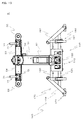
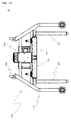
- Embodiment 2 9 to 14 show a robot R according to Embodiment 2 of the present invention. As shown in FIGS.
- the robot R includes a base 100 that can be freely moved, a lifting shaft 51 that is erected on the base 100, a turning shaft 52 that is attached to the upper end of the lifting shaft 51, A first telescopic shaft 53 and a second telescopic shaft 54 that are mounted symmetrically at the tip of the pivot shaft 52, and a rod-shaped first arm that protrudes forward from the tip of the first telescopic shaft 53 ( A right arm) 55, a rod-like second arm (left arm) 56, which is arranged to protrude forward from the tip of the second telescopic shaft 54, a drive power source 57, and an operation panel 70 as main components. It is supposed to be.
- the robot R travels by pushing and pulling the robot R while holding the manual operation levers 74 and 74.
- the base portion 100 includes a placement portion 110 disposed in the central portion, and a traveling portion 160 disposed on both sides of the placement portion 110.
- the mounting unit 110 includes a mounting member 120 disposed in the central portion and a horizontal support member 130 disposed in the left-right direction that supports the mounting member 120.
- the traveling unit 160 includes a front traveling unit 170 and a rear traveling unit 180.
- the front traveling unit 170 includes a front wheel 171 and a front wheel support member 172 that supports the front wheel 171
- the rear traveling unit 180 includes a rear wheel 181 and a rear wheel support member 182 that supports the rear wheel 181. It is supposed to be.
- the front wheel support member 172 and the rear wheel support member 182 are joined to the horizontal support member 130 through appropriate means. Further, the diameter of the front wheel 171 is smaller than the diameter of the rear wheel 181.
- the mounting portion 110 more specifically, the mounting member 120, is provided with a lifting shaft 51, a driving power source 57, an operation panel 70, and the like.
- the front wheel support member 172 includes a front horizontal portion 173 and a rear inclined portion 174 having an upward slope, and a front wheel 171 is attached to the tip of the horizontal portion 173. Since the front wheel 171 has a small diameter and the front wheel support member 172 is configured as described above, the front traveling portion 170 can be submerged under the bed.
- the elevating shaft 51 is made of, for example, an electric cylinder.
- the turning shaft 52 is made of, for example, an electric servo motor.
- the first telescopic shaft 53 and the second telescopic shaft 54 are made of, for example, an electric cylinder.
- the driving power source 57 is a battery, for example. As shown in FIG.
- the operation panel 70 includes a robot operation button 71, a head side instruction lever 72 that indicates whether the position of the head of the care recipient is the right side or the left side of the robot R, A switch 73, a manual operation lever (manual operation means) 74, and a control unit 80 are provided.
- the robot operation button 71 is provided on the top of a manual operation lever 74 provided on each of the right cover CR covering the first telescopic shaft 53 and the left cover CL covering the second telescopic shaft 54. Yes.
- the robot operation button 71 enables the robot R to operate only when both buttons 71 and 71 are pressed simultaneously from the viewpoint of fail-safe. As shown in FIG.
- the manual operation lever 74 includes a switching function unit 74 a that switches the position force control switching unit 81 that switches between position control and force control, and a lifting shaft operation function unit 74 b that drives the lifting shaft 1.
- a swing axis operation function unit 74c for driving the swing axis 2 a first extension shaft operation function unit 74d for driving the first extension shaft 53, and a second extension shaft operation function unit 74e for driving the second extension shaft 54.
- Each functional unit is realized by adjusting the angle and inclination of the lever.
- the control unit 80 includes a position force control switching unit 81 that switches between position control and force control, a lift shaft drive control unit 82 that controls the drive of the lift shaft 51, and a swing axis drive that controls the drive of the swing shaft 52.
- the control unit 83, the first telescopic shaft drive control unit 84 for controlling the driving of the first telescopic shaft 53, the second telescopic shaft drive control unit 85 for controlling the driving of the second telescopic shaft 54, and the respective units are integrated. And a supervising section 86 that performs the above. For example, when the robot operation buttons 71 and 71 are being pressed, the general unit 86 responds to the operation of each means, for example, the turning operation of the turning shaft 52, the extending and retracting operation of the extension shafts 53 and 54, and the raising and lowering of the lifting shaft 51. It is assumed that the control that enables the operation is performed.
- the turning shaft drive control means 83 has a turning angle limiting portion 83a that restricts the turning angle of the turning shaft 52 in response to a signal from the head side instruction lever 72.
- the turning angle restriction unit 83a restricts the turning angle of the turning shaft 52 so that the head of the care recipient is not positioned below the horizontal.
- the control part 80 which has this function is implement
- Procedure 2 The lifting / lowering axis operation function unit 74b is operated by lever operation while pressing the robot operation buttons 71 and 71, and the lifting / lowering axis 51 is appropriately driven to set the heights of the right arm 55 and the left arm 56 to the held portion of the dedicated seat 30. 31 is the height position.
- Step 3 The first telescopic shaft 53 and the second telescopic shaft 54 are appropriately operated by causing the first telescopic shaft operation function unit 74d and the second telescopic shaft operation function unit 74e to function by lever operation while pressing the robot operation buttons 71, 71. Driven so that the right arm 55 and the left arm 56 face the held portions 31, 31, respectively.
- Procedure 4 The robot R is advanced and the right arm 55 and the left arm 56 are inserted into the held portions 31 and 31 of the dedicated sheet 30, respectively.
- Procedure 5 The head side instruction lever 72 is used to indicate the side of the head of the care recipient. That is, it indicates whether the head of the care recipient is on the right side or the left side of the robot R.
- Procedure 8 The lifting / lowering axis operation function unit 74b is operated by lever operation while pressing the robot operation buttons 71 and 71, and the lifting / lowering axis 51 is appropriately driven to bring the dedicated seat 30 to a predetermined height from the bed. In other words, the care recipient is lifted from the bed.
- Procedure 9 The switching function unit 74a is operated by lever operation while pressing the robot operation buttons 71, 71 to switch the robot R from position control to force control.
- Procedure 10 The robot R is moved backward and the care recipient is moved to the bedside.
- Procedure 11 The switching function unit 74a is operated by lever operation while pressing the robot operation buttons 71, 71 to switch the robot R from force control to position control.
- Step 12 While turning the robot operation buttons 71 and 71, the turning axis operation function unit 74c is operated by lever operation to drive the turning axis 52 to raise the head of the care recipient while lowering the toes.
- Step 13 The robot R is switched from position control to force control by causing the switching function unit 74a to function by lever operation while pressing the robot operation buttons 71, 71. After making the posture of the care recipient in this way, the caregiver transfers the care recipient to a wheelchair or the like.
- the robot R of this embodiment it is not necessary for the caregiver to lift the care recipient from the bed, and the burden on the caregiver is reduced. For example, low back pain called a caregiver's occupational disease can be eliminated.
- FIG. 17 shows an operation panel 70A for a robot according to Embodiment 3 of the present invention.
- the third embodiment is a modification of the second embodiment, and is configured so that an operation by manual operation and an operation by automatic control can be performed. That is, as shown in FIG.
- the operation panel 70A includes a manual automatic switching lever (manual automatic switching means) 75, an operation pattern selection button (operation pattern selection means) 76, and a control. It is assumed that an operation pattern holding unit 88 is added to the unit 80. Hereinafter, the automatic operation will be described.
- the manual automatic switching lever 75 is switched to automatic and one of the operation pattern selection buttons 76 is pressed to select an automatic operation pattern, the corresponding pattern held in the automatic operation pattern holding unit 88 is called and the pattern is called.
- the robot R performs the operation according to the above.
- the first telescopic shaft 53 and the second telescopic shaft 54 are appropriately driven to cause the first telescopic shaft 53 and the second telescopic shaft 54 to expand and contract as appropriate while the swivel shaft 52 is swung.
- the robot R By causing the robot R to perform such an operation, it appears as if the robot R is dancing and gives a healing effect to the care recipient.
- FIG. 18 shows a state in which two robots R having a decorative cover are arranged to face each other and are automatically operated. By doing so, it gives the impression that the robots R and R are dressed up, and the healing effect is increased.
- a trumpet-shaped guide portion 32 a may be formed on the side where the arm 5 b of the robot R of the held portion 31 of the dedicated sheet 30 is inserted.
- power is generated by a battery held by the robot, but power may be supplied from a commercial power source by a cord.
- the present invention can be applied to the robot industry and the nursing care business.
Landscapes
- Health & Medical Sciences (AREA)
- Life Sciences & Earth Sciences (AREA)
- Animal Behavior & Ethology (AREA)
- General Health & Medical Sciences (AREA)
- Public Health (AREA)
- Veterinary Medicine (AREA)
- Nursing (AREA)
- Invalid Beds And Related Equipment (AREA)
Priority Applications (7)
| Application Number | Priority Date | Filing Date | Title |
|---|---|---|---|
| CA2881311A CA2881311C (fr) | 2012-09-19 | 2013-09-17 | Methode de soins et robot de soins |
| KR1020157004554A KR102090850B1 (ko) | 2012-09-19 | 2013-09-17 | 간호 방법 및 그것에 이용하는 간호 로봇 |
| AU2013318942A AU2013318942B2 (en) | 2012-09-19 | 2013-09-17 | Care method and care robot used therein |
| DK13839700.5T DK2898865T3 (da) | 2012-09-19 | 2013-09-17 | Pleje-fremgangsmåde og plejerobot, der anvendes ved denne |
| CN201380048394.1A CN104661630A (zh) | 2012-09-19 | 2013-09-17 | 看护方法以及在该看护方法中使用的看护机器人 |
| EP13839700.5A EP2898865B1 (fr) | 2012-09-19 | 2013-09-17 | Méthode de soins et robot de soins |
| US14/642,136 US10272006B2 (en) | 2012-09-19 | 2015-03-09 | Care method and care robot used therein |
Applications Claiming Priority (4)
| Application Number | Priority Date | Filing Date | Title |
|---|---|---|---|
| JP2012-206401 | 2012-09-19 | ||
| JP2012206401A JP6074654B2 (ja) | 2012-09-19 | 2012-09-19 | ロボット |
| JP2012206385A JP6142116B2 (ja) | 2012-09-19 | 2012-09-19 | 介護方法およびそれに用いる介護ロボット |
| JP2012-206385 | 2012-09-19 |
Related Child Applications (1)
| Application Number | Title | Priority Date | Filing Date |
|---|---|---|---|
| US14/642,136 Continuation US10272006B2 (en) | 2012-09-19 | 2015-03-09 | Care method and care robot used therein |
Publications (1)
| Publication Number | Publication Date |
|---|---|
| WO2014046292A1 true WO2014046292A1 (fr) | 2014-03-27 |
Family
ID=50341591
Family Applications (1)
| Application Number | Title | Priority Date | Filing Date |
|---|---|---|---|
| PCT/JP2013/075960 Ceased WO2014046292A1 (fr) | 2012-09-19 | 2013-09-17 | Méthode de soins et robot de soins |
Country Status (8)
| Country | Link |
|---|---|
| US (1) | US10272006B2 (fr) |
| EP (1) | EP2898865B1 (fr) |
| KR (1) | KR102090850B1 (fr) |
| CN (1) | CN104661630A (fr) |
| AU (1) | AU2013318942B2 (fr) |
| CA (1) | CA2881311C (fr) |
| DK (1) | DK2898865T3 (fr) |
| WO (1) | WO2014046292A1 (fr) |
Cited By (3)
| Publication number | Priority date | Publication date | Assignee | Title |
|---|---|---|---|---|
| WO2015181874A1 (fr) * | 2014-05-26 | 2015-12-03 | 株式会社安川電機 | Dispositif d'aide au transfert |
| WO2015181873A1 (fr) * | 2014-05-26 | 2015-12-03 | 株式会社安川電機 | Dispositif d'assistance au transfert |
| JP2016067753A (ja) * | 2014-09-30 | 2016-05-09 | 株式会社安川電機 | スリングシート、移乗補助装置、移乗補助方法 |
Families Citing this family (10)
| Publication number | Priority date | Publication date | Assignee | Title |
|---|---|---|---|---|
| CA2920283C (fr) * | 2013-10-18 | 2020-07-14 | Muscle Corporation | Robot servant au transfert d'un patient |
| JP6565090B2 (ja) | 2016-02-10 | 2019-08-28 | 株式会社国際電気通信基礎技術研究所 | 回転構造、アシストシステム、および、ロボット |
| CN106142096A (zh) * | 2016-06-04 | 2016-11-23 | 浙江侍维波机器人科技有限公司 | 含可变形态机械臂的搬运和抱抬肥胖症病人的医疗机器人 |
| CN105877933A (zh) * | 2016-06-04 | 2016-08-24 | 浙江侍维波机器人科技有限公司 | 含紧急救护机器人的自主运载系统 |
| CN106420226B (zh) * | 2016-10-13 | 2019-05-17 | 天津大学 | 重伤病患柔性换乘转运机器人 |
| KR102031057B1 (ko) | 2017-09-27 | 2019-10-15 | 한국과학기술연구원 | 환자 이송 장치 |
| CN111467138A (zh) * | 2020-03-31 | 2020-07-31 | 中南大学湘雅医院 | 一种操作灵活、使用方便胸外科疾病检查装置 |
| CN112545791A (zh) * | 2020-12-11 | 2021-03-26 | 广东全影汇信息科技有限公司 | 一种多功能护理床 |
| CN112660969B (zh) * | 2020-12-30 | 2021-08-27 | 亚洲富士电梯股份有限公司 | 具有防护结构的加装电梯以及制造设备与制造工艺 |
| KR102507726B1 (ko) | 2020-12-31 | 2023-03-09 | (주)맨엔텔 | 추락방지, 전동주행 및 중력보상 기능을 포함한 통합제어 및 이에 대한 모니터링이 가능한 이승 로봇 시스템 |
Citations (5)
| Publication number | Priority date | Publication date | Assignee | Title |
|---|---|---|---|---|
| JP2002136549A (ja) | 2000-11-06 | 2002-05-14 | Okuma Seisakusho:Kk | 介護用キャリア |
| JP2002253623A (ja) * | 2001-03-01 | 2002-09-10 | Iura:Kk | 介護用リフト |
| WO2009147832A1 (fr) * | 2008-06-06 | 2009-12-10 | パナソニック株式会社 | Robot, dispositif de commande de robot, procédé de commande et programme de commande |
| JP2010029420A (ja) * | 2008-07-29 | 2010-02-12 | Toyota Motor Corp | 移乗用ベッドのマットレス及び移乗方法 |
| JP2011172898A (ja) * | 2010-01-29 | 2011-09-08 | Nobuo Ueda | 介護用リフト |
Family Cites Families (20)
| Publication number | Priority date | Publication date | Assignee | Title |
|---|---|---|---|---|
| US2035840A (en) * | 1934-03-30 | 1936-03-31 | Sechrist | Invalid lifting apparatus |
| US2418606A (en) * | 1944-09-18 | 1947-04-08 | Smith Ralph Nichol | Invalid lift and transfer device |
| FR93658E (fr) * | 1967-02-21 | 1969-05-02 | Etienne Joseph Jean | Appareil notamment pour le transport des malades. |
| US3813712A (en) * | 1972-06-28 | 1974-06-04 | N Bonnin | Patient stretcher transport system |
| AU6262973A (en) * | 1972-12-01 | 1975-05-22 | Campbell D I | Trolleys |
| GB1444802A (fr) * | 1973-03-06 | 1976-08-04 | ||
| US4649581A (en) * | 1984-12-12 | 1987-03-17 | Lee Jr John P | Patient lift assembly |
| US5084921A (en) * | 1991-01-18 | 1992-02-04 | Hicks Jr George W | Supine patient lift and transfer apparatus |
| JPH09168566A (ja) * | 1995-12-18 | 1997-06-30 | Shinmeiwa Auto Eng Kk | 車椅子 |
| GB2319226A (en) * | 1996-11-01 | 1998-05-20 | Phillip Henry Slocombe | Hospital trolley |
| GB2381256A (en) * | 2001-09-29 | 2003-04-30 | Collette Fellows-Smith | Patient lifting device |
| DE20317997U1 (de) * | 2003-11-20 | 2004-04-01 | Coopmans, Wilhelm Richard, Dipl.-Ing. | Transportvorrichtung zum Personentransport |
| US20050135907A1 (en) * | 2003-11-24 | 2005-06-23 | Romano James P. | Medical lift and transport system, method and apparatus |
| JP2009515560A (ja) * | 2005-03-14 | 2009-04-16 | エルゴ アシスト テクノロジー リミテッド ライアビリティ カンパニー | 関連フレーム及びリフトカート付き患者移動システム |
| US7434278B2 (en) * | 2005-06-29 | 2008-10-14 | Elizabeth Ann White | Apparatus for patient mobility |
| JP2007252469A (ja) * | 2006-03-22 | 2007-10-04 | Matsushita Electric Ind Co Ltd | 支持装置およびそれを用いた介護ロボット装置 |
| US20100115695A1 (en) * | 2006-04-12 | 2010-05-13 | White Elizabeth A | Dampened Belt Retractor |
| US20080066228A1 (en) * | 2006-09-20 | 2008-03-20 | Yohei Kume | Supporting apparatus and nursing robot system |
| JPWO2008129847A1 (ja) * | 2007-04-12 | 2010-07-22 | パナソニック株式会社 | 移乗支援装置 |
| US8397320B2 (en) * | 2010-12-23 | 2013-03-19 | Guido Capaldi | Patient lifting device |
-
2013
- 2013-09-17 CA CA2881311A patent/CA2881311C/fr active Active
- 2013-09-17 WO PCT/JP2013/075960 patent/WO2014046292A1/fr not_active Ceased
- 2013-09-17 DK DK13839700.5T patent/DK2898865T3/da active
- 2013-09-17 CN CN201380048394.1A patent/CN104661630A/zh active Pending
- 2013-09-17 KR KR1020157004554A patent/KR102090850B1/ko active Active
- 2013-09-17 AU AU2013318942A patent/AU2013318942B2/en active Active
- 2013-09-17 EP EP13839700.5A patent/EP2898865B1/fr active Active
-
2015
- 2015-03-09 US US14/642,136 patent/US10272006B2/en active Active
Patent Citations (5)
| Publication number | Priority date | Publication date | Assignee | Title |
|---|---|---|---|---|
| JP2002136549A (ja) | 2000-11-06 | 2002-05-14 | Okuma Seisakusho:Kk | 介護用キャリア |
| JP2002253623A (ja) * | 2001-03-01 | 2002-09-10 | Iura:Kk | 介護用リフト |
| WO2009147832A1 (fr) * | 2008-06-06 | 2009-12-10 | パナソニック株式会社 | Robot, dispositif de commande de robot, procédé de commande et programme de commande |
| JP2010029420A (ja) * | 2008-07-29 | 2010-02-12 | Toyota Motor Corp | 移乗用ベッドのマットレス及び移乗方法 |
| JP2011172898A (ja) * | 2010-01-29 | 2011-09-08 | Nobuo Ueda | 介護用リフト |
Cited By (3)
| Publication number | Priority date | Publication date | Assignee | Title |
|---|---|---|---|---|
| WO2015181874A1 (fr) * | 2014-05-26 | 2015-12-03 | 株式会社安川電機 | Dispositif d'aide au transfert |
| WO2015181873A1 (fr) * | 2014-05-26 | 2015-12-03 | 株式会社安川電機 | Dispositif d'assistance au transfert |
| JP2016067753A (ja) * | 2014-09-30 | 2016-05-09 | 株式会社安川電機 | スリングシート、移乗補助装置、移乗補助方法 |
Also Published As
| Publication number | Publication date |
|---|---|
| AU2013318942B2 (en) | 2018-12-06 |
| AU2013318942A1 (en) | 2015-03-05 |
| EP2898865A4 (fr) | 2016-09-14 |
| CN104661630A (zh) | 2015-05-27 |
| DK2898865T3 (da) | 2019-09-09 |
| US10272006B2 (en) | 2019-04-30 |
| KR20150058166A (ko) | 2015-05-28 |
| EP2898865B1 (fr) | 2019-07-10 |
| EP2898865A1 (fr) | 2015-07-29 |
| KR102090850B1 (ko) | 2020-03-18 |
| US20150173988A1 (en) | 2015-06-25 |
| CA2881311A1 (fr) | 2014-03-27 |
| CA2881311C (fr) | 2020-10-06 |
Similar Documents
| Publication | Publication Date | Title |
|---|---|---|
| WO2014046292A1 (fr) | Méthode de soins et robot de soins | |
| US9414980B2 (en) | Bed, and combining method and separating method of bed | |
| JP6715533B2 (ja) | 移乗装置 | |
| JP2011098005A (ja) | 介護用ストレッチャー | |
| JP6142116B2 (ja) | 介護方法およびそれに用いる介護ロボット | |
| JP6074654B2 (ja) | ロボット | |
| KR102150594B1 (ko) | 휠체어 | |
| JPS601022B2 (ja) | 看護ロボツト | |
| KR20120059999A (ko) | 좌석의 승강 및 전후방향 이동이 가능한 휠체어 | |
| JP6169418B2 (ja) | 移乗支援装置 | |
| JP6340352B2 (ja) | ベッド装置 | |
| JP4903000B2 (ja) | 立ち上がり支援装置 | |
| JP6257462B2 (ja) | 電動移乗機 | |
| JP5792269B2 (ja) | 介護者補助装置 | |
| KR101171520B1 (ko) | 전동침대 | |
| JP5707371B2 (ja) | ベッド装置 | |
| JP4146682B2 (ja) | 起床式ベッド装置 | |
| JP6052951B2 (ja) | 歩行補助装置 | |
| JP2013090647A (ja) | 移乗支援装置及び移乗支援装置の制御方法 | |
| JP7213052B2 (ja) | 身体支持装置 | |
| JP2011147522A (ja) | 移乗支援装置 | |
| JP2004223150A (ja) | 移乗補助機器 | |
| JP2019000306A (ja) | 移乗支援装置 | |
| JP2005131386A (ja) | 可動ベッド | |
| JP2000254179A (ja) | 車椅子 |
Legal Events
| Date | Code | Title | Description |
|---|---|---|---|
| 121 | Ep: the epo has been informed by wipo that ep was designated in this application |
Ref document number: 13839700 Country of ref document: EP Kind code of ref document: A1 |
|
| ENP | Entry into the national phase |
Ref document number: 2881311 Country of ref document: CA |
|
| ENP | Entry into the national phase |
Ref document number: 20157004554 Country of ref document: KR Kind code of ref document: A |
|
| ENP | Entry into the national phase |
Ref document number: 2013318942 Country of ref document: AU Date of ref document: 20130917 Kind code of ref document: A |
|
| NENP | Non-entry into the national phase |
Ref country code: DE |