WO2014045979A1 - 化学強化ガラスの製造方法 - Google Patents
化学強化ガラスの製造方法 Download PDFInfo
- Publication number
- WO2014045979A1 WO2014045979A1 PCT/JP2013/074584 JP2013074584W WO2014045979A1 WO 2014045979 A1 WO2014045979 A1 WO 2014045979A1 JP 2013074584 W JP2013074584 W JP 2013074584W WO 2014045979 A1 WO2014045979 A1 WO 2014045979A1
- Authority
- WO
- WIPO (PCT)
- Prior art keywords
- molten salt
- tank
- glass
- chemical strengthening
- regeneration
- Prior art date
- Legal status (The legal status is an assumption and is not a legal conclusion. Google has not performed a legal analysis and makes no representation as to the accuracy of the status listed.)
- Ceased
Links
Images



Classifications
-
- C—CHEMISTRY; METALLURGY
- C03—GLASS; MINERAL OR SLAG WOOL
- C03C—CHEMICAL COMPOSITION OF GLASSES, GLAZES OR VITREOUS ENAMELS; SURFACE TREATMENT OF GLASS; SURFACE TREATMENT OF FIBRES OR FILAMENTS MADE FROM GLASS, MINERALS OR SLAGS; JOINING GLASS TO GLASS OR OTHER MATERIALS
- C03C21/00—Treatment of glass, not in the form of fibres or filaments, by diffusing ions or metals in the surface
- C03C21/001—Treatment of glass, not in the form of fibres or filaments, by diffusing ions or metals in the surface in liquid phase, e.g. molten salts, solutions
- C03C21/002—Treatment of glass, not in the form of fibres or filaments, by diffusing ions or metals in the surface in liquid phase, e.g. molten salts, solutions to perform ion-exchange between alkali ions
Definitions
- the present invention relates to a method for producing chemically tempered glass by ion exchange, and more particularly to a method for producing chemically tempered glass having a stable quality by regenerating and reusing molten salt used for chemically strengthening the glass.
- Glass that has been chemically strengthened by ion exchange or the like (hereinafter also referred to as “chemically strengthened glass”) is used for a cover glass of a display device such as a digital camera, a mobile phone, and a PDA (Personal Digital Assistants) and a glass substrate of the display. It has been. Although glass has a high theoretical strength, the strength is greatly reduced by scratching. Chemically tempered glass has a higher mechanical strength than unstrengthened glass and prevents the glass surface from being scratched.
- the chemical strengthening treatment of the glass by ion exchange is performed by substituting a metal ion (for example, Na ion) having a small ionic radius and a metal ion (for example, K ion) having a larger ionic radius contained in the glass.
- a compressive stress layer is formed to improve the strength of the glass.
- the glass When Na 2 O is contained in the glass composition, the glass is immersed in a molten salt (inorganic potassium salt) containing K ions, and Na ions in the glass and K ions in the molten salt are ion-exchanged.
- a molten salt inorganic potassium salt
- the molten salt an inorganic potassium salt that is in a molten state at the strengthening treatment temperature is used, and potassium nitrate is often used among them.
- CS surface compressive stress
- Patent Document 1 In order to continue to obtain the desired CS value, in Patent Document 1, the temperature of the molten salt subjected to the chemical strengthening treatment is lowered and dissolved in water to precipitate the salt, and after solid-liquid separation, the salt is brought to a temperature higher than the melting point. A method for remelting the molten salt by remelting is disclosed.
- Patent Document 2 discloses a method of dividing the chemical strengthening process into two stages and increasing the DOL by coarse strengthening in the first stage and securing the CS value of the surface in the second stage.
- Patent Document 3 in order to suppress large variability in compressive stress and continuous periodic variation of chemically strengthened glass, all or part of the molten salt is discarded and replaced with a new molten salt that has not been subjected to ion exchange. A method is disclosed.
- Patent Document 3 since all or part of the molten salt is discarded, the amount of waste is very large and costly. Therefore, it is realistic to actually perform chemical strengthening treatment of glass using the method. There was room for improvement.
- An object of the present invention is to provide a method for producing chemically strengthened glass at low cost.
- the inventors transferred a part of the molten salt deteriorated by the chemical strengthening of the glass to a separate tank (second tank) independent of the chemical strengthening tank (first tank).
- the present invention found that a stable CS value can be imparted to glass while realizing a reduction in the amount of waste and low cost by carrying out a regeneration treatment of the molten salt in the process, and transferring the regenerated molten salt to a strengthening tank. It came to be completed.
- the present invention is as follows.
- ⁇ 1> A method for producing chemically strengthened glass in which a glass containing sodium is immersed in a first tank including a molten salt containing potassium nitrate, and a compressive stress layer is formed on the surface of the glass, Transferring a part of the molten salt in the first tank to the second tank; Adding potassium phosphate to the molten salt in the transferred second tank, Separating the sodium compound precipitated in the molten salt in the second tank after the addition of the potassium phosphate from the molten salt; and transferring the molten salt after the sodium compound separation to the first tank;
- a method for producing chemically strengthened glass comprising: ⁇ 2> The chemically strengthened glass according to ⁇ 1>, wherein the temperature T 1 of the molten salt in the first tank and the temperature T 2 of the molten salt in the second tank satisfy a relationship of T 1 ⁇ T 2 .
- chemically strengthened glass having a stable quality can be continuously produced by one-step strengthening while regenerating and reusing the molten salt.
- the throughput can be improved, and the amount of molten salt raw material used for chemical strengthening can be reduced at the same time as the amount of waste is greatly reduced, thereby reducing the cost.
- FIG. 1 is a schematic view showing an example of the entire apparatus for producing chemically strengthened glass.
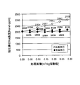
- FIG. 2 is a graph showing the relationship between the glass treatment area per molten salt weight and the Na concentration in the strengthening tank in the production methods of Example 1 and Comparative Example 1.
- FIG. 3 is a graph showing the relationship between the glass treatment area per molten salt weight and the CS value in the production methods of Example 1 and Comparative Example 1.
- FIG. 4 is a graph showing the relationship between the glass treatment area per molten salt weight and the amount of waste in the production methods of Example 1 and Comparative Example 2.
- FIG. 5 is a graph showing the relationship between the glass treatment area per weight of molten salt and the waste reduction rate in the production method of Example 1.
- the chemically strengthened glass is obtained by immersing a glass plate containing Na in a first tank (also referred to as a chemical strengthening tank or simply a strengthening tank) provided with a molten salt containing potassium nitrate, on the surface of the glass. It is obtained by forming a compressive stress layer.
- a part of the molten salt in the first tank (chemical strengthening tank) is extracted and transferred to the second tank (also referred to as a regeneration tank or a sedimentation tank), and phosphoric acid is added to the molten salt in the transferred second tank.
- Add potassium By the addition of the potassium phosphate, a Na-containing compound is precipitated in the molten salt, so that the Na ion concentration in the molten salt is reduced and the molten salt is regenerated.
- the molten salt from which the Na-containing precipitate has been separated is transferred again to the first tank (chemical strengthening tank), so that the glass is chemically strengthened to produce chemically strengthened glass having a stable CS value. be able to.
- the method for producing chemically strengthened glass according to the present invention can be applied, for example, to a chemical strengthening apparatus as shown in FIG. .
- Step 5 Molten salt regeneration step (adding potassium phosphate, stirring, standing)
- Step 6 Extraction of regenerated molten salt
- 7 ′ Preheating the regenerated molten salt from which the Na has been removed to the strengthening temperature
- Step 1 Preparation of molten salt
- Step 2 Chemical strengthening of glass
- Step 4 Extraction of molten salt from tempering tank (part of molten salt in tempering tank is extracted into regeneration tank)
- Step 4 ′ Adjusting the temperature of the regeneration tank to a predetermined temperature
- Step 5 Molten salt regeneration step (adding potassium phosphate, stirring, standing)
- Step 6 Extraction of regenerated molten salt
- Step 7 Removal of Na-containing precipitates
- 7 ' Preheating the regenerated molten salt from which the Na has been removed to the strengthening temperature
- Step 8 Returning the regenerated molten salt from which the Na has been removed to the strengthening tank 10: Chemical strengthening process that repeats steps 2 to 8 above
- a part of the molten salt is intermittently extracted from the chemical strengthening tank, and after the regeneration treatment in the regeneration tank, the molten salt after the regeneration treatment is returned to the chemical strengthening tank. Go through a circular process.
- the continuous regeneration process of aspect B a part of the molten salt is continuously extracted from the chemical strengthening tank and regenerated in the regeneration tank, and then the molten salt after the regeneration is returned to the chemical strengthening tank. Go through a circular process. That is, the difference between Aspect B and Aspect B is whether the operation of extracting the molten salt to be subjected to the regeneration process from the chemical strengthening tank is performed intermittently or continuously. Step 3 and step 9 for confirming the Na concentration in the strengthening tank are not included.
- Step 1 an inorganic potassium salt is charged into the preparation tank 3, and the molten salt is prepared by heating and melting to a temperature equal to or higher than the melting point of the inorganic potassium salt. This is put into a chemical strengthening tank (strengthening tank, first tank) 1.
- the inorganic potassium salt is preferably one that is in a molten state below the strain point (usually 500 to 600 ° C.) of the glass to be chemically strengthened.
- it contains potassium nitrate (melting point 330 ° C.).
- potassium nitrate is a main component because it is in a molten state below the strain point of the glass and is easy to handle in a general temperature range when a chemical strengthening treatment is performed.
- the main component means 50% by mass or more in the molten salt.
- the molten salt may contain other inorganic potassium salts in addition to potassium nitrate, and examples thereof include combinations with one or more selected from alkali sulfates such as potassium sulfate and potassium chloride, alkali chlorides and potassium carbonate, and the like. .
- the mixed molten salt of potassium nitrate and potassium carbonate has a lower rate of decrease in ion exchange capacity due to an increase in Na concentration and a longer life of the molten salt compared to a molten salt consisting only of potassium nitrate, so the frequency of regeneration is reduced. From the viewpoint of cost reduction due to the above.
- the addition amount of potassium carbonate needs to be not more than the saturation solubility at the set temperature of the chemical strengthening tank 1 and the regeneration tank (sedimentation tank, second tank) 2 and is preferably 15% by mass or less with respect to potassium nitrate. In addition, 15 mass% is equivalent to the saturated dissolution amount of potassium carbonate with respect to potassium nitrate at 470 ° C.
- the inorganic potassium salt is melted. Since potassium nitrate has a melting point of 330 ° C. and a boiling point of 500 ° C., it is preferably carried out within that temperature range. In particular, it is more preferable that the melting temperature be 350 ° C. or more and 500 ° C. or less from the viewpoint of the balance between the CS value that can be imparted to the glass and the stress depth (DOL) and the strengthening time.
- DOL stress depth
- the order of addition of potassium nitrate and other inorganic potassium salts is not limited, and either may be added first or simultaneously.
- the stirring time in the case of stirring for mixing is not particularly limited, but is preferably 1 minute to 10 hours, and more preferably 10 minutes to 2 hours.
- the inorganic potassium salt to be added exceeds the saturation solubility for potassium nitrate, K 2 CO 3 , K 3 PO 4 , NaHCO 3 , NaK 2 PO 4, etc. may be precipitated. It is allowed to stand until it settles or a solid-liquid separation operation is performed, and only the liquid is transferred to the chemical strengthening tank 1.
- Materials such as metal, quartz and ceramics can be used for the preparation tank 3 for melting the inorganic potassium salt.
- a metal material is preferable from the viewpoint of durability, and a stainless steel (SUS) material is preferable from the viewpoint of corrosion resistance.
- step 2 the glass is chemically strengthened.
- the molten salt prepared in step 1 is transferred from the preparation tank 3, and the chemical strengthening tank 1 including the molten salt containing potassium nitrate is defined as the first tank.
- the temperature of the molten salt in the chemical strengthening tank 1 is adjusted to a temperature at which chemical strengthening is performed.
- glass containing Na is preheated. The glass will be described in detail later.
- Processing formation of a compressive stress layer on the surface of the glass is performed.
- the chemical strengthening treatment is performed by immersing the glass in a molten salt and ion-exchanging the metal ions in the glass with ions in the molten salt having an ionic radius larger than that of the metal ions.
- the ion exchange changes the composition of the glass surface, and compressive stress is generated in the glass surface layer, thereby strengthening the glass.
- the glass preheating temperature depends on the temperature at which the chemical strengthening treatment is performed (temperature of the salt bath), but is generally preferably 100 ° C. or higher.
- the chemical tempering temperature of the glass is preferably not more than the strain point (usually 500 to 600 ° C.) of the glass to be tempered, and preferably 350 ° C. or more in order to obtain a higher depth of compressive stress (Depth of Layer: DOL).
- the immersion time of the glass in the molten salt is preferably 10 minutes to 12 hours, more preferably 30 minutes to 10 hours. If it exists in this range, the chemically strengthened glass excellent in the balance of an intensity
- the chemical strengthening tank 1 that performs the chemical strengthening treatment can use metal, quartz, ceramics, or the like.
- a metal material is preferable from the viewpoint of durability, and a stainless steel (SUS) material is preferable from the viewpoint of corrosion resistance.
- Step 3 If the chemical strengthening treatment of the glass is continued in Step 2, a desired ion exchange amount cannot be obtained according to the glass treatment area, and the CS value imparted to the glass is lowered. Therefore, in step 3, the degree of deterioration of the molten salt is determined. As the chemical treatment continues, Na ions are dissolved from the glass in the molten salt, and as the area of the treated glass increases, the Na ion concentration in the molten salt increases and the ion exchange capacity between K ions and Na ions decreases. To do. The ion exchange amount decreases due to a decrease in ion exchange capacity, leading to a decrease in the CS value imparted to the glass.
- the deterioration state of the molten salt is investigated by measuring the Na ion concentration in the molten salt or the CS value of the glass after chemical strengthening, and the molten salt can be used continuously, or after step 4 described later. It is determined whether or not the molten salt needs to be regenerated.
- the Na concentration in the molten salt can be measured by ICP emission spectrometry or atomic absorption spectrometry, and the CS value of the glass after chemical strengthening treatment can be measured by a surface stress meter (Orihara Seisakusho FSM-6000LE).
- the control value of CS required by the type of glass or the Na concentration in the molten salt corresponding to the control value of CS is defined each time. Perform the playback process. However, when performing the chemical strengthening treatment of the glass and the regeneration treatment of the molten salt using the “continuous regeneration process” represented by the aspect B, the molten salt is continuously regenerated regardless of the Na ion concentration in the molten salt. Therefore, it is not necessary to perform this step 3.
- step 4 in order to perform the regeneration treatment of the molten salt subjected to the glass chemical strengthening treatment, a part of the molten salt is transferred from the first tank (chemical strengthening tank 1) to the second tank (regeneration tank (sedimentation tank) 2).
- the molten salt is transferred by the molten salt transfer means 4.
- a known method such as a pump, pumping, pumping out, or siphoning can be used for feeding the molten salt.
- the size of the regeneration tank 2 that is the destination of the molten salt may be determined according to the size of the chemical strengthening tank 1 and the Na ion concentration range to be controlled, and is not particularly limited. Among these, from the viewpoint of continuous strengthening treatment in the strengthening tank 1 and equipment costs, the size of the regeneration tank 2 is preferably 1 ⁇ 2 or less of the volume of the chemical strengthening tank 1.
- the size of the regeneration tank 2 is determined based on the Na ion concentration range to be controlled is shown below.
- the concentration management of the Na ion concentration in the chemical strengthening tank 1 is in the range of 1800 to 2000 ppm
- the Na ion concentration in the strengthening tank 1 is 2000 ppm
- the frequency of regenerating the molten salt can be arbitrarily determined according to the Na ion concentration control range in the strengthening tank 1.
- the regeneration tank 2 is preferably preheated to 330 ° C. or higher in advance so that the transferred molten salt does not solidify.
- the regeneration tank 2 that performs the molten salt regeneration process can use metal, quartz, ceramics, or the like.
- a metal material is preferable from the viewpoint of durability, and a stainless steel (SUS) material is preferable from the viewpoint of corrosion resistance.
- the temperature of the regeneration tank 2 can be arbitrarily selected depending on how much the Na ion concentration of the transferred molten salt is reduced. As the regeneration temperature is lower, the Na ion concentration can be lowered even if the amount of potassium phosphate added in Step 5 is reduced, and the Na removal efficiency is increased. This is due to the fact that the lower the temperature, the lower the saturation solubility of the Na salt, and the greater the amount of precipitation. Since the improvement of Na removal efficiency leads to a reduction in the amount of potassium phosphate added, a cost reduction effect can be obtained.
- the regeneration temperature T 2 is preferably in the range of 350 to 500 ° C., and from the viewpoint of temperature dependence of solubility, T 2 should be such that the inequality T 1 ⁇ T 2 with respect to the chemical strengthening temperature T 1 . Is preferred. Further, the temperature difference between T 1 and T 2 is preferably 0 to 150 ° C. from the viewpoint of the temperature dependence of the solubility of the Na-containing precipitate. As described above, in step 4 ', the temperature T 2 of the regeneration tank 2 is adjusted so as to satisfy the above requirements.
- step 5 the molten salt is regenerated.
- the molten salt By adding potassium phosphate to the molten salt transferred to the regeneration tank 2, the molten salt can be regenerated so that a desired CS value can be given again.
- Na ions in the molten salt increased by chemical strengthening treatment and K ions of potassium phosphate were ion-exchanged to precipitate Na and solidify and separate the supernatant. It can be reused as a molten salt (regenerated molten salt).
- the temperature T 2 of the regeneration tank 2 can be arbitrarily selected depending on how much the Na ion concentration of the transferred molten salt is lowered as described in the step 4 ′.
- the lower the regeneration temperature the lower the Na ion concentration even if the amount of potassium phosphate added is reduced. This is due to the fact that the lower the temperature, the lower the saturation solubility of the Na salt, and the greater the amount of precipitation. Since the improvement of Na removal efficiency leads to a reduction in the amount of potassium phosphate added, a cost reduction effect can be obtained.
- Play temperature T 2 is preferably in the range of 350 ⁇ 500 ° C., from the viewpoint of the temperature dependence of the solubility, T 2 for chemical strengthening temperature T 1, it is preferable that the T 1 ⁇ T 2.
- potassium phosphate added to the molten salt examples include potassium orthophosphate (K 3 PO 4 ), potassium pyrophosphate (K 4 P 2 O 7 ), and potassium metaphosphate ((KPO 3 ) n ). You may use together in combination. Of these, potassium orthophosphate is preferable from the viewpoint of Na removal efficiency during melting.
- the amount of potassium phosphate added is determined in consideration of the temperature of the regeneration treatment, the concentration of Na ions in the transferred molten salt, and the amount of molten salt to be regenerated. For example, the upper limit of the added amount of potassium orthophosphate when the regeneration temperature is 470 ° C. and the liquid phase recovery rate is 50% is preferably 22% by mass or less.
- potassium orthophosphate When potassium orthophosphate is added as potassium phosphate, the potassium orthophosphate may be hydrated or dehydrated.
- the content of potassium orthophosphate added to the molten salt is preferably 0.1% by mass to 25% by mass with respect to the molten salt. If it is this range, it is preferable from a viewpoint of making a liquid recovery rate more than a desired ratio.
- potassium pyrophosphate When potassium pyrophosphate is added as potassium phosphate, potassium pyrophosphate may be hydrated or dehydrated.
- the content of potassium pyrophosphate added to the molten salt is preferably 0.1% by mass to 25% by mass with respect to the molten salt. If it is this range, it is preferable from a viewpoint of making a liquid recovery rate more than a desired ratio.
- potassium metaphosphate When potassium metaphosphate is added as potassium phosphate, the potassium metaphosphate may be hydrated or dehydrated.
- the content of potassium metaphosphate added to the molten salt is preferably 0.1% by mass to 25% by mass with respect to the molten salt. If it is this range, it is preferable from a viewpoint of making a liquid recovery rate more than a desired ratio.
- the precipitated Na-containing compound hereinafter also referred to as “Na-containing precipitate”
- the liquid phase regenerated molten salt
- the molten salt in the regeneration tank 2 can be separated into a liquid phase and a sediment containing precipitates by standing after stirring for a certain time.
- the sediment contains KNO 3 , K 2 NaPO 4 , KNaCO 3 , K 2 O and the like.
- the liquid phase contains KNO 3 , K 2 CO 3 and the like.
- the stirring conditions after the addition of potassium phosphate are not particularly limited as long as the molten salt and potassium phosphate are mixed without a shortage. Moreover, it does not specifically limit about the stationary conditions after stirring, What is necessary is just to stand still until Na containing precipitate precipitates completely. The time required for the precipitate to settle completely depends on the particle size of the precipitate, and the smaller the particle size, the longer the time is required, but 30 minutes to 10 hours are preferable. However, in the case where a solid-liquid separation device such as a filter or a centrifugal separator is used, the standing step is not necessary.
- Step 6 the regenerated molten salt (supernatant liquid, supernatant) after separating the Na-containing precipitate in step 5 is extracted.
- the extraction method can be arbitrarily selected, and examples thereof include pumping and pumping.
- Step 7 the Na-containing precipitate that has precipitated in the lower portion of the regeneration tank 2 in step 5 is removed out of the system.
- the removal method can be arbitrarily selected, and examples thereof include pumping and pumping. Note that either step 6 or step 7 may be performed first.
- Step 7 ′ is a step of preheating the molten salt from which Na has been removed (regeneration treatment) to the strengthening temperature.
- the regenerated molten salt extracted in the step 6 after finishing the regenerating process is reduced by removing the precipitate generated in the regenerating process in the step 7. Therefore, when returning the molten salt (recycled molten salt) that has been regenerated to the strengthening tank 1, a new molten salt that has not been subjected to the chemical strengthening process so as to have the same amount as the amount of the molten salt extracted in step 4.
- Add The molten salt composition to be added is the same as the composition charged into the strengthening tank 1 in step 1.
- preheating Before transferring the regenerated molten salt after removal of Na to the strengthening tank 1, preheating is performed to the same temperature as the strengthening tank 1. By this heating, the regenerated molten salt can be introduced into the strengthening tank 1 without reducing the throughput in the chemical strengthening treatment.
- Step 8 the regenerated molten salt preheated in Step 7 is returned to the chemical strengthening tank 1, but the transfer means is not particularly limited. Specific examples include pumping and pressure feeding using a siphon.
- Step 9 In the case of the batch regeneration process represented by the aspect A, in Step 9, after returning the regenerated molten salt to the chemical strengthening tank 1 in Step 8, the Na ion concentration in the chemical strengthening tank 1 is measured. If the Na ion concentration has not decreased to the desired value (the desired CS value cannot be obtained by the chemical strengthening process), Steps 4 to 8 are repeated again. Similarly to step 3, the Na ion concentration can be measured by ICP emission analysis or atomic absorption analysis, and the CS value can be measured by a surface stress meter (Orihara Seisakusho FSM-6000LE). When the chemical strengthening treatment of glass and the regeneration treatment of molten salt are performed using the “continuous regeneration process” represented by the aspect B, this step 9 is not necessary.
- step 10 In the case of the batch regeneration process of aspect A, if it can be confirmed in step 9 that the Na ion concentration in the chemical strengthening tank 1 has decreased to a desired value, the process returns to the chemical strengthening treatment step for glass in step 2 as step 10; The process up to step 9 is repeated.
- the molten salt is extracted from the strengthening tank 1 while being subjected to the chemical strengthening treatment of the glass regardless of the Na ion concentration in the strengthening tank 1, and then to the regeneration tank 2.
- a series of steps of transferring the molten salt, regenerating the molten salt, and transferring the regenerated molten salt to the strengthening tank 1 are performed. Therefore, in the process 10 in the aspect B, when the regenerated molten salt is returned to the strengthening tank 1 in the process 8, the process from the chemical strengthening treatment process of the glass in the process 2 to the process 8 is repeated.
- a chemically strengthened glass is manufactured while processing a molten salt so as to obtain a desired CS value continuously (stably) for a molten salt containing potassium nitrate.
- a tank for performing chemical strengthening treatment (strengthening tank 1) and a tank for performing molten salt regeneration treatment (regeneration tank 2) are separately performed to reinforce the molten salt regeneration. Since it is not necessary to interrupt the treatment and the chemical strengthening treatment of the glass can be performed continuously, the throughput can be improved.
- the molten salt is circulated continuously or intermittently for recycling and reuse, the amount of waste generated is reduced. For the same reason, since the amount of the molten salt raw material that needs to be newly added is small, the molten salt cost can be reduced.
- the glass used in the present invention only needs to contain sodium, and glass having various compositions can be used as long as it has a composition that can be strengthened by molding and chemical strengthening treatment.
- Specific examples include soda lime glass, aluminosilicate glass, borosilicate glass, lead glass, alkali barium glass, and aluminoborosilicate glass.
- the method for producing the glass is not particularly limited, and a desired glass raw material is charged into a continuous melting furnace, and the glass raw material is heated and melted preferably at 1500 to 1600 ° C., clarified, and then supplied to a molding apparatus. It can be manufactured by forming into a plate shape and slowly cooling.
- various methods can be employed for forming the glass.
- various forming methods such as a down draw method (for example, an overflow down draw method, a slot down method and a redraw method), a float method, a roll-out method, and a press method can be employed.
- the thickness of the glass is not particularly limited, but is usually preferably 5 mm or less and more preferably 3 mm or less in order to effectively perform the chemical strengthening treatment.
- the total content of SiO 2 and Al 2 O 3 is 75% or less, the total content of Na 2 O and K 2 O is 12 to 25%, and the total content of MgO and CaO is 7 to 15%.
- composition which is displayed at a certain glass (iii) mol%, a SiO 2 68 ⁇ 80%, the Al 2 O 3 4 ⁇ 10% ,
- the a 2 O 5 ⁇ 15%, the K 2 O 0 to 1%, the MgO 4 ⁇ 15% and ZrO 2 is composition displaying a glass (iv) mole% containing 0 to 1%, a SiO 2 67 -75%, Al 2 O 3 0-4%, Na 2 O 7-15%, K 2 O 1-9%, MgO 6-14% and ZrO 2 0-1.5%
- the total content of SiO 2 and Al 2 O 3 is 71 to 75%, the total content of Na 2 O and K 2 O is 12 to 20%, and when CaO is contained, the content is 1% Glass that is less than
- Glass may be polished before chemical strengthening treatment as necessary.
- the polishing method include a method of polishing with a polishing pad while supplying a polishing slurry.
- a polishing slurry a polishing slurry containing an abrasive and water can be used.
- the abrasive cerium oxide (ceria) and silica are preferable.
- the washing liquid is preferably a neutral detergent and water, and more preferably washed with water after washing with a neutral detergent.
- a commercially available neutral detergent can be used.
- the glass substrate cleaned by the cleaning process is finally cleaned with a cleaning solution.
- the cleaning liquid include water, ethanol, and isopropanol. Of these, water is preferred.
- the glass is dried.
- the drying conditions may be selected in consideration of the cleaning solution used in the cleaning process, the characteristics of the glass, and the like.
- Aluminosilicate glass was used as the chemically strengthened glass.
- the composition of the glass is as follows.
- the concentration of Na ions in the chemical strengthening tank was measured with an atomic absorption photometer (Hitachi High-Tech Z-2310) by dissolving the recovered molten salt in an aqueous nitric acid solution and adding cesium chloride to suppress ion interference. Quantified by
- the molten salt and precipitates that could not be recovered for transferring the recycled molten salt to the strengthening tank are defined as waste, and the total amount of the waste is defined as the amount of waste.
- the amount of waste was measured. The amount of waste was determined by calculating the difference between the recycle container weight after recovering the regenerated molten salt solution and the recycle container empty weight.
- the amount of waste in Examples 1-2 to 1-6 and Comparative Examples 2-2 to 2-5 includes the amount of waste discharged up to the previous process of the Example or Comparative Example, and the cumulative amount thereof. Is expressed as the amount of waste.
- the waste reduction rate is W1 when the molten salt extracted from the strengthening tank is recycled / reused, and when the entire amount of molten salt extracted from the strengthening tank is discarded. Assuming that the amount of waste of W2 is W2, it was calculated by (W2-W1) / W2 ⁇ 100.
- Example 1 (Preparation of molten salt and chemical strengthening treatment) To a SUS preparation tank / strengthening tank, 2816 g of potassium nitrate, 162 g of potassium carbonate and 22 g of sodium nitrate were added and heated to 430 ° C. with a mantle heater to prepare a deteriorated molten salt.
- the deterioration represents a state in which a part of K in the molten salt is replaced with Na and the CS value obtained by the chemical strengthening treatment becomes low.
- the Na ion concentration in the molten salt was 2037 ppm.
- an aluminosilicate glass having a total surface area of 0.14 m 2 was preheated to 100 ° C.
- the glass was washed with ion exchange water at 100 ° C. and dried at 60 ° C. for 2 hours.
- CS value surface compressive stress
- DOL compressive stress layer depth
- Example 1-2 An aluminosilicate glass having a total surface area of 0.14 m 2 was preheated to 100 ° C. and immersed in the molten salt after finishing Example 1-1 for 8 hours to perform chemical strengthening treatment. Thereafter, the glass was washed with ion exchange water at 100 ° C. and dried at 60 ° C. for 2 hours.
- the CS value and DOL of the glass after chemical strengthening treatment were 812 MPa and 57 ⁇ m, respectively, and the CS value and DOL equivalent to those of Example 1-1 were obtained. Further, the Na concentration in the molten salt after the chemical strengthening treatment increased from 1970 ppm to 2206 ppm.
- the molten salt is extracted and regenerated in the following steps: the amount of molten salt extracted from the strengthening tank is 328 g (11% by mass of the total), and the amount of K 3 PO 4 .3H 2 O to be added is 8.5 g (molten salt to be regenerated). However, it was carried out under the same conditions as in Example 1-1 except that K 3 PO 4 was 2.0% by mass. As for the liquid transfer to the strengthening tank, the liquid was transferred again into the strengthening tank under the same conditions as in Example 1-1 except that the regenerated liquid to be transferred was 245 g (regeneration tank liquid phase recovery rate 75%).
- Example 1-3 An aluminosilicate glass having a total surface area of 0.14 m 2 was preheated to 100 ° C. and immersed in the molten salt after finishing Example 1-2 for 8 hours to perform chemical strengthening treatment. Thereafter, the glass was washed with ion exchange water at 100 ° C. and dried at 60 ° C. for 2 hours.
- the CS value and DOL of the glass after chemical strengthening treatment were 813 MPa and 57 ⁇ m, respectively, and the CS value and DOL equivalent to those of Example 1-1 were obtained. Further, the Na concentration in the molten salt after the chemical strengthening treatment increased from 1998 ppm to 2146 ppm.
- the molten salt is extracted and regenerated in the following steps: 320 g (11% by mass of the total amount) of molten salt extracted from the strengthening tank, and 8.2 g of the amount of K 3 PO 4 ⁇ 3H 2 O to be added (molten salt to be regenerated) However, it was carried out under the same conditions as in Example 1-1 except that K 3 PO 4 was 2.0% by mass. As for the liquid transfer to the strengthening tank, the liquid was transferred again into the strengthening tank under the same conditions as in Example 1-1 except that the regenerated liquid to be transferred was 290 g (recovery tank liquid phase recovery rate 91%).
- Example 1-4 An aluminosilicate glass having a total surface area of 0.14 m 2 was preheated to 100 ° C. and immersed in the molten salt after completion of Example 1-3 for 8 hours for chemical strengthening treatment. Thereafter, the glass was washed with ion exchange water at 100 ° C. and dried at 60 ° C. for 2 hours.
- the CS value and DOL of the glass after chemical strengthening treatment were 811 MPa and 56 ⁇ m, respectively, and the CS value and DOL equivalent to those of Example 1-1 were obtained. Further, the Na concentration in the molten salt after the chemical strengthening treatment increased from 1966 ppm to 2123 ppm.
- the amount of the molten salt extracted from the strengthening tank was 315 g (11% by mass of the whole), and the amount of K 3 PO 4 ⁇ 3H 2 O added was 8.1 g (the molten salt subjected to the regeneration treatment). However, it was carried out under the same conditions as in Example 1-1 except that K 3 PO 4 was 2.0% by mass.
- the liquid transfer to the strengthening tank the liquid was transferred again into the strengthening tank under the same conditions as in Example 1-1, except that the regenerated liquid to be transferred was 287 g (regeneration tank liquid phase recovery rate 91%).
- Example 1-5 An aluminosilicate glass having a total surface area of 0.14 m 2 was preheated to 100 ° C. and immersed in the molten salt after finishing Example 1-4 for 8 hours to perform chemical strengthening treatment. Thereafter, the glass was washed with ion exchange water at 100 ° C. and dried at 60 ° C. for 2 hours.
- the CS value and DOL of the glass after chemical strengthening treatment were 808 MPa and 56 ⁇ m, respectively, and the CS value and DOL equivalent to those of Example 1-1 were obtained.
- the Na concentration in the molten salt after the chemical strengthening treatment increased from 1978 ppm to 2158 ppm.
- the molten salt is extracted and regenerated in the amount of 311 g (10% by mass of the total amount) of molten salt extracted from the strengthening tank and 8.0 g (molten salt to be regenerated) of K 3 PO 4 .3H 2 O to be added. However, it was carried out under the same conditions as in Example 1-1 except that K 3 PO 4 was 2.0% by mass. As for the liquid transfer to the strengthening tank, the liquid was transferred again into the strengthening tank under the same conditions as in Example 1-1 except that the regenerated liquid to be transferred was changed to 282 g (regeneration tank liquid phase recovery rate 91%).
- Example 1-6 Aluminosilicate glass having a total surface area of 0.14 m 2 was preheated to 100 ° C. and immersed in the molten salt after finishing Example 1-5 for 8 hours to perform chemical strengthening treatment. Thereafter, the glass was washed with ion exchange water at 100 ° C. and dried at 60 ° C. for 2 hours.
- the CS value and DOL of the glass after the chemical strengthening treatment were 814 MPa and 55 ⁇ m, respectively, and the CS value and DOL equivalent to those of Example 1-1 were obtained. Further, the Na concentration in the molten salt after the chemical strengthening treatment increased from 1989 ppm to 2151 ppm.
- the molten salt is extracted and regenerated in the following steps: 312 g of molten salt extracted from the strengthening tank (11% by mass of the total), and 8.2 g of molten K 3 PO 4 .3H 2 O to be added (molten salt to be regenerated) However, it was carried out under the same conditions as in Example 1-1 except that K 3 PO 4 was 2.0% by mass. As for the liquid transfer to the strengthening tank, the liquid was transferred again into the strengthening tank under the same conditions as in Example 1-1 except that the regenerated liquid to be transferred was 284 g (regeneration tank liquid phase recovery rate 91%).
- Comparative Example 1 [Comparative Example 1-1] An aluminosilicate glass having a total surface area of 0.14 m 2 is preheated to 100 ° C., the chemical strengthening treatment in Example 1-1 is finished, and immersed in a molten salt (Na concentration: 2126 ppm) that has not been regenerated for 8 hours. Chemical strengthening treatment was performed. Thereafter, the glass was washed with ion exchange water at 100 ° C. and dried at 60 ° C. for 2 hours. Further, the Na concentration in the molten salt after the chemical strengthening treatment increased from 2123 ppm to 2354 ppm.
- a molten salt Na concentration: 2126 ppm
- Comparative Example 1-2 An aluminosilicate glass having a total surface area of 0.14 m 2 was preheated to 100 ° C. and immersed in the molten salt after completion of Comparative Example 1-1 for 8 hours for chemical strengthening treatment. Thereafter, the glass was washed with ion exchange water at 100 ° C. and dried at 60 ° C. for 2 hours.
- the CS value and DOL of the glass after the chemical strengthening treatment were 797 MPa and 62 ⁇ m, respectively. Further, the Na concentration in the molten salt after the chemical strengthening treatment increased from 2354 ppm to 2497 ppm.
- Comparative Example 1-3 An aluminosilicate glass having a total surface area of 0.14 m 2 was preheated to 100 ° C. and immersed in the molten salt after completion of Comparative Example 1-2 for 8 hours to perform chemical strengthening treatment. Thereafter, the glass was washed with ion exchange water at 100 ° C. and dried at 60 ° C. for 2 hours. Further, the Na concentration in the molten salt after the chemical strengthening treatment increased from 2497 ppm to 2661 ppm.
- Comparative Example 1-4 An aluminosilicate glass having a total surface area of 0.14 m 2 was preheated to 100 ° C. and immersed in the molten salt after completion of Comparative Example 1-3 for 8 hours to perform chemical strengthening treatment. Thereafter, the glass was washed with ion exchange water at 100 ° C. and dried at 60 ° C. for 2 hours. Further, the Na concentration in the molten salt after the chemical strengthening treatment increased from 2661 ppm to 2842 ppm.
- Comparative Example 2 [Comparative Example 2-1] After chemical strengthening treatment, 301 g of molten salt is extracted from the strengthening tank, and the entire amount (301 g) of the molten salt is discarded without regenerating, and 301 g of new molten salt (potassium nitrate containing 4 mol% of potassium carbonate) is used in the strengthening tank. Except for the addition, the glass was chemically strengthened and the molten salt in the strengthening tank was exchanged under the same conditions as in Example 1-1. Here, since no regeneration treatment was performed, the amount of waste was 301 g because it corresponds to the total amount of molten salt extracted from the strengthening tank, and was 0.100 kg when converted to the amount of waste per kg of molten salt. .
- [Comparative Example 2-3] Aluminosilicate glass having a total surface area of 0.14 m 2 was preheated to 100 ° C. and immersed in the molten salt after completion of Comparative Example 2-2 for 8 hours to perform chemical strengthening treatment. Thereafter, the glass was washed with ion exchange water at 100 ° C. and dried at 60 ° C. for 2 hours. After the chemical strengthening treatment, 320 g of molten salt was extracted from the strengthening tank, the entire amount was discarded, and 320 g of new molten salt (potassium nitrate containing 4 mol% of potassium carbonate) was charged into the strengthening tank. The amount of waste at this time was (629 g + 320 g) 949 g, which was 0.316 kg in terms of the amount of waste per kg of molten salt.
- [Comparative Example 2-4] Aluminosilicate glass having a total surface area of 0.14 m 2 was preheated to 100 ° C. and immersed in the molten salt after completion of Comparative Example 2-3 for 8 hours to perform chemical strengthening treatment. Thereafter, the glass was washed with ion exchange water at 100 ° C. and dried at 60 ° C. for 2 hours. After the chemical strengthening treatment, 315 g of the molten salt was extracted from the strengthening tank, the entire amount was discarded, and 315 g of a new molten salt (potassium nitrate containing 4 mol% of potassium carbonate) was put into the strengthening tank. The amount of waste at this time was (949 g + 315 g) 1264 g, which was 0.421 kg in terms of the amount of waste per kg of molten salt.
- Example 1 Na concentration in molten salt, regeneration conditions, CS value and DOL in Example 1 (1-1 to 1-6), and Na concentration in molten salt in Comparative Example 1 (1-1 to 1-5)
- Table 1 shows the reproduction condition, CS value, and DOL. Furthermore, the graph showing the relationship between the glass processing area per molten salt weight of these Example 1 and Comparative Example 1 and the Na density
- Table 2 shows the amount of waste in Example 1 (1-1 to 1-6) and the amount of waste in Comparative Example 2 (2-1 to 2-6). Further, when the entire amount of the molten salt extracted from the strengthening tank without being regenerated is discarded (Comparative Examples 2-1 to 2-6), when the regenerating process is performed (Examples 1-1 to 1-6) ) Is the waste reduction rate (%) and is also shown in Table 2. Furthermore, the graph showing the relationship between the glass processing area per molten salt weight and the amount of waste in these Example 1 and Comparative Example 2 is shown in FIG. 4, with the glass processing area per molten salt weight and the waste reduction rate. A graph showing the relationship is shown in FIG.
- a part of the molten salt is taken out from the tempering tank and subjected to a regeneration treatment, and the recycled molten salt is reused to be subjected to the chemical strengthening treatment of the glass.
Landscapes
- Chemical & Material Sciences (AREA)
- Life Sciences & Earth Sciences (AREA)
- Engineering & Computer Science (AREA)
- Chemical Kinetics & Catalysis (AREA)
- General Chemical & Material Sciences (AREA)
- Geochemistry & Mineralogy (AREA)
- Materials Engineering (AREA)
- Organic Chemistry (AREA)
- Surface Treatment Of Glass (AREA)
Abstract
本発明は硝酸カリウムを含有する溶融塩を備える第1槽に、ナトリウムを含有するガラスを浸漬し、前記ガラスの表面に圧縮応力層を形成する化学強化ガラスの製造方法であって、前記第1槽内の溶融塩の一部を第2槽に移送する工程、移送された前記第2槽内の溶融塩にリン酸カリウムを添加する工程、前記リン酸カリウムの添加後の第2槽内の溶融塩中に析出したナトリウム化合物を、溶融塩から分離する工程、及び前記ナトリウム化合物分離後の溶融塩を前記第1槽に移送する工程、を含む、化学強化ガラスの製造方法に関する。
Description
本発明は、イオン交換により化学強化ガラスを製造する方法に関し、中でもガラスを化学強化するために用いる溶融塩を再生、再利用することにより、品質が安定した化学強化ガラスを製造する方法に関する。
デジタルカメラ、携帯電話およびPDA(Personal Digital Assistants)といったディスプレイ装置などのカバーガラスおよびディスプレイのガラス基板には、イオン交換等で化学強化処理したガラス(以下、「化学強化ガラス」ともいう。)が用いられている。ガラスは理論強度が高いものの、傷がつくことで強度が大幅に低下する。化学強化ガラスは、未強化のガラスに比べて機械的強度が高く、ガラス表面に傷がつくのを防ぐため、上記用途に好適である。
イオン交換によるガラスの化学強化処理は、ガラス中に含まれるイオン半径の小さな金属イオン(例えば、Naイオン)とイオン半径のより大きな金属イオン(例えば、Kイオン)とを置換することにより、ガラス表面に圧縮応力層を生じさせてガラスの強度を向上させる処理である。
ガラス組成中にNa2Oを含む場合、Kイオンを含む溶融塩(無機カリウム塩)にガラスを浸漬し、ガラス中のNaイオンと溶融塩中のKイオンとをイオン交換する。溶融塩は強化処理温度で溶融状態となる無機カリウム塩が用いられるが、中でも硝酸カリウムが用いられることが多い。
化学強化ガラスの評価方法のひとつとして、表面圧縮応力(Compressive Stress:CS)が挙げられる。化学強化処理後にガラスに対して最大のCS値を付与することができるのは、イオン交換に供していない溶融塩(新しい溶融塩)を用いた時に限られ、実際には累積ガラス処理面積に応じて、得られるCS値は徐々に低下してしまう。CSが低下する要因は、イオン交換によりガラス中から溶出するNaイオンによって硝酸カリウム溶融塩が希釈されることに起因し、Naイオン濃度とCS低下には相関があることが知られている。
所望のCS値を得続けるために、特許文献1では化学強化処理に供した溶融塩の温度を下げて水に溶かすことで塩を析出し、固液分離した後に、塩を融点以上の温度にして再溶融させて溶融塩を再生する方法が開示されている。
特許文献2には化学強化処理をする工程を2段に分け、1段目では粗強化によりDOLを高め、2段目では表面のCS値を確保する方法が開示されている。
特許文献3には、化学強化ガラスの圧縮応力の大きな変動性と絶え間ない周期的ばらつきを抑制するために、溶融塩の全部または一部を廃棄し、イオン交換に供していない新しい溶融塩に交換する方法が開示されている。
特許文献2には化学強化処理をする工程を2段に分け、1段目では粗強化によりDOLを高め、2段目では表面のCS値を確保する方法が開示されている。
特許文献3には、化学強化ガラスの圧縮応力の大きな変動性と絶え間ない周期的ばらつきを抑制するために、溶融塩の全部または一部を廃棄し、イオン交換に供していない新しい溶融塩に交換する方法が開示されている。
しかしながら、特許文献1に記載の再生方法では、溶融塩を水に溶解させるために、大量の廃棄物が発生する。また、溶融塩を再生するにあたって、水への溶解、析出、分離、再溶融という一連の工程を多数要するために、設備面やコスト面への負荷が大きく、エネルギーロスも大きい。そこで、廃棄物量の低減、製造エネルギーの低減、スループットの改善などの点で改善の余地があった。
また、特許文献2に記載の方法では、溶融塩中のNa劣化速度が遅いことから溶融塩のライフ(寿命)は長いと言えるものの、溶融塩の交換、希釈は必須であり、その際には大量の廃棄物が発生する。また、化学強化工程を2段に分けて行うために、予熱、放冷などの前処理工程、後処理工程を各々2回繰り返す必要があり、スループットが低下する懸念があった。また、工程ごとに同じ大きさの強化槽が2槽必要となることから、初期投資やメンテナンスの問題と共に空間的な制約が生じうる。
さらに、特許文献3では溶融塩の全部または一部を廃棄するために廃棄物量が非常に多く、コストがかかることから、実際に当該方法を用いてガラスの化学強化処理をすることは現実的でなく、改善の余地があった。
そこで本発明では、所望のCS値を連続して(安定して)得られるように溶融塩を再生処理しながら化学強化ガラスを製造する方法であって、発生する廃棄物量の低減やスループットの向上などにより、低コストで化学強化ガラスを製造する方法を提供することを目的とする。
本発明者らは、ガラスの化学強化により劣化した溶融塩の一部を、化学強化を行う槽(第1槽)とは独立した別個の槽(第2槽)に移送し、当該別個の槽で溶融塩の再生処理を行い、再生後の溶融塩を強化槽に移送することにより、廃棄物量の削減と低コストを実現しつつ、ガラスに安定したCS値を付与できることを見出し、本発明を完成するに至った。
すなわち、本発明は以下の通りである。
<1> 硝酸カリウムを含有する溶融塩を備える第1槽に、ナトリウムを含有するガラスを浸漬し、前記ガラスの表面に圧縮応力層を形成する化学強化ガラスの製造方法であって、
前記第1槽内の溶融塩の一部を第2槽に移送する工程、
移送された前記第2槽内の溶融塩にリン酸カリウムを添加する工程、
前記リン酸カリウムの添加後の第2槽内の溶融塩中に析出したナトリウム化合物を、溶融塩から分離する工程、及び
前記ナトリウム化合物分離後の溶融塩を前記第1槽に移送する工程、
を含む、化学強化ガラスの製造方法。
<2> 前記第1槽内の溶融塩の温度T1及び前記第2槽内の溶融塩の温度T2がT1≧T2の関係を満たす、前記<1>に記載の化学強化ガラスの製造方法。
<3> 前記第1槽内の溶融塩が、さらに炭酸カリウムを含有する前記<1>又は<2>に記載の化学強化ガラスの製造方法。
<4> 前記リン酸カリウムがオルトリン酸カリウムである前記<1>~<3>のいずれか1に記載の化学強化ガラスの製造方法。
<1> 硝酸カリウムを含有する溶融塩を備える第1槽に、ナトリウムを含有するガラスを浸漬し、前記ガラスの表面に圧縮応力層を形成する化学強化ガラスの製造方法であって、
前記第1槽内の溶融塩の一部を第2槽に移送する工程、
移送された前記第2槽内の溶融塩にリン酸カリウムを添加する工程、
前記リン酸カリウムの添加後の第2槽内の溶融塩中に析出したナトリウム化合物を、溶融塩から分離する工程、及び
前記ナトリウム化合物分離後の溶融塩を前記第1槽に移送する工程、
を含む、化学強化ガラスの製造方法。
<2> 前記第1槽内の溶融塩の温度T1及び前記第2槽内の溶融塩の温度T2がT1≧T2の関係を満たす、前記<1>に記載の化学強化ガラスの製造方法。
<3> 前記第1槽内の溶融塩が、さらに炭酸カリウムを含有する前記<1>又は<2>に記載の化学強化ガラスの製造方法。
<4> 前記リン酸カリウムがオルトリン酸カリウムである前記<1>~<3>のいずれか1に記載の化学強化ガラスの製造方法。
本発明に係る化学強化ガラスの製造方法によれば、溶融塩を再生及び再利用しながら、品質(CS値)が安定した化学強化ガラスを一段強化で連続的に製造することができる。その結果、スループットの向上が可能となり、廃棄物量の大幅な低減と同時に化学強化に供する溶融塩原料の量を低減できることから、コストダウンも可能となる。
以下、本発明を詳細に説明する。
なお本明細書において“質量%”と“重量%”とは同義である。また、“質量ppm”と“重量ppm”とは同義である。
本発明において、化学強化ガラスは、硝酸カリウムを含有する溶融塩を備える第1槽(化学強化槽、または単に強化槽とも言う。)に、Naを含有するガラス板を浸漬し、前記ガラスの表面に圧縮応力層を形成することにより得られる。ここで、第1槽(化学強化槽)中の溶融塩の一部を抜き出して第2槽(再生槽または沈降槽とも言う)に移送し、移送された第2槽内の溶融塩にリン酸カリウムを添加する。当該リン酸カリウムの添加により、溶融塩中にはNa含有化合物が析出するので、溶融塩中のNaイオン濃度は低下し、溶融塩が再生される。当該Na含有析出物を分離した溶融塩を再び第1槽(化学強化槽)へと移送することで、ガラスの化学強化処理を引き続き行い、安定したCS値が付与された化学強化ガラスを製造することができる。
なお本明細書において“質量%”と“重量%”とは同義である。また、“質量ppm”と“重量ppm”とは同義である。
本発明において、化学強化ガラスは、硝酸カリウムを含有する溶融塩を備える第1槽(化学強化槽、または単に強化槽とも言う。)に、Naを含有するガラス板を浸漬し、前記ガラスの表面に圧縮応力層を形成することにより得られる。ここで、第1槽(化学強化槽)中の溶融塩の一部を抜き出して第2槽(再生槽または沈降槽とも言う)に移送し、移送された第2槽内の溶融塩にリン酸カリウムを添加する。当該リン酸カリウムの添加により、溶融塩中にはNa含有化合物が析出するので、溶融塩中のNaイオン濃度は低下し、溶融塩が再生される。当該Na含有析出物を分離した溶融塩を再び第1槽(化学強化槽)へと移送することで、ガラスの化学強化処理を引き続き行い、安定したCS値が付与された化学強化ガラスを製造することができる。
本発明に係る化学強化ガラスの製造方法は、例えば図1に示したような化学強化処理装置を、例えば化学強化工程と溶融塩の再生、再利用工程を含む以下の態様において適用することができる。
<態様A:バッチ再生プロセス>
工程1:溶融塩の調製
工程2:ガラスの化学強化
工程3:溶融塩劣化の判断
工程4:強化槽からの溶融塩の抜き出し(強化槽中溶融塩の一部を再生槽に抜きだし)
工程4’:再生槽の温度を所定温度に調整
工程5:溶融塩再生工程(リン酸カリウムを添加、攪拌、静置)
工程6:再生溶融塩の抜き出し
工程7:Na含有析出物の除去
工程7’:Na除去した再生溶融塩を強化温度に予備加熱
工程8:Na除去した再生溶融塩を強化槽に戻す
工程9:強化槽中Na濃度の確認
工程10:上記工程2~工程9を繰り返す化学強化プロセス
<態様A:バッチ再生プロセス>
工程1:溶融塩の調製
工程2:ガラスの化学強化
工程3:溶融塩劣化の判断
工程4:強化槽からの溶融塩の抜き出し(強化槽中溶融塩の一部を再生槽に抜きだし)
工程4’:再生槽の温度を所定温度に調整
工程5:溶融塩再生工程(リン酸カリウムを添加、攪拌、静置)
工程6:再生溶融塩の抜き出し
工程7:Na含有析出物の除去
工程7’:Na除去した再生溶融塩を強化温度に予備加熱
工程8:Na除去した再生溶融塩を強化槽に戻す
工程9:強化槽中Na濃度の確認
工程10:上記工程2~工程9を繰り返す化学強化プロセス
<態様B:連続再生プロセス>
工程1:溶融塩の調製
工程2:ガラスの化学強化
工程4:強化槽からの溶融塩の抜き出し(強化槽中溶融塩の一部を再生槽に抜きだし)
工程4’:再生槽の温度を所定温度に調整
工程5:溶融塩再生工程(リン酸カリウムを添加、攪拌、静置)
工程6:再生溶融塩の抜き出し
工程7:Na含有析出物の除去
工程7’:Na除去した再生溶融塩を強化温度に予備加熱
工程8:Na除去した再生溶融塩を強化槽に戻す
工程10:上記工程2~工程8を繰り返す化学強化プロセス
工程1:溶融塩の調製
工程2:ガラスの化学強化
工程4:強化槽からの溶融塩の抜き出し(強化槽中溶融塩の一部を再生槽に抜きだし)
工程4’:再生槽の温度を所定温度に調整
工程5:溶融塩再生工程(リン酸カリウムを添加、攪拌、静置)
工程6:再生溶融塩の抜き出し
工程7:Na含有析出物の除去
工程7’:Na除去した再生溶融塩を強化温度に予備加熱
工程8:Na除去した再生溶融塩を強化槽に戻す
工程10:上記工程2~工程8を繰り返す化学強化プロセス
態様Aのバッチ再生プロセスでは、化学強化槽から断続的に溶融塩の一部を抜き出して再生槽で再生処理をした後、当該再生処理後の溶融塩を化学強化槽に戻すといった、溶融塩の循環プロセスを経る。
態様Bの連続再生プロセスでは、化学強化槽から連続的に溶融塩の一部を抜き出して再生槽で再生処理をした後、当該再生処理後の溶融塩を化学強化槽に戻すといった、溶融塩の循環プロセスを経る。
すなわち、態様Aと態様Bとでは再生処理に供する溶融塩を化学強化槽から抜き出す作業を断続的に行うか、連続的に行うかという点で異なり、態様Bには溶融塩劣化の判断をする工程3と、強化槽中のNa濃度を確認する工程9が含まれない。
態様Bの連続再生プロセスでは、化学強化槽から連続的に溶融塩の一部を抜き出して再生槽で再生処理をした後、当該再生処理後の溶融塩を化学強化槽に戻すといった、溶融塩の循環プロセスを経る。
すなわち、態様Aと態様Bとでは再生処理に供する溶融塩を化学強化槽から抜き出す作業を断続的に行うか、連続的に行うかという点で異なり、態様Bには溶融塩劣化の判断をする工程3と、強化槽中のNa濃度を確認する工程9が含まれない。
以下、各工程について図1を用いて説明する。
(工程1)
工程1では、無機カリウム塩を調製槽3に投入し、当該無機カリウム塩の融点以上の温度に加熱溶融して貯留することで、溶融塩の調製を行う。これを化学強化槽(強化槽、第1槽)1へ投入する。
(工程1)
工程1では、無機カリウム塩を調製槽3に投入し、当該無機カリウム塩の融点以上の温度に加熱溶融して貯留することで、溶融塩の調製を行う。これを化学強化槽(強化槽、第1槽)1へ投入する。
無機カリウム塩は化学強化を行うガラスの歪点(通常500~600℃)以下で溶融状態になるものが好ましく、本発明においては硝酸カリウム(融点330℃)を含有する。さらに硝酸カリウムが主成分であれば、ガラスの歪点以下で溶融状態となり、さらに化学強化処理を施す場合に一般的な温度領域において取り扱いが容易である点から好ましい。ここで主成分とは、溶融塩中、50質量%以上であることを意味する。
溶融塩として硝酸カリウム以外に他の無機カリウム塩を含んでいてもよく、例えば、硫酸カリウム、塩化カリウム等のアルカリ硫酸塩や、アルカリ塩化塩、炭酸カリウム等から選ばれる一種以上との組み合わせが挙げられる。
中でも、硝酸カリウムと炭酸カリウムの混合溶融塩は、硝酸カリウムのみからなる溶融塩と比べて、Na濃度上昇によるイオン交換能力の低下率が低くなり、溶融塩の寿命が長くなることから、再生頻度の低下等によるコストの低減の点で好ましい。
炭酸カリウムの添加量は、化学強化槽1及び再生槽(沈降槽、第2槽)2の設定温度における飽和溶解度以下である必要があり、硝酸カリウムに対して15質量%以下が好ましい。なお、15質量%とは、470℃における硝酸カリウムに対する炭酸カリウムの飽和溶解量に相当する。
中でも、硝酸カリウムと炭酸カリウムの混合溶融塩は、硝酸カリウムのみからなる溶融塩と比べて、Na濃度上昇によるイオン交換能力の低下率が低くなり、溶融塩の寿命が長くなることから、再生頻度の低下等によるコストの低減の点で好ましい。
炭酸カリウムの添加量は、化学強化槽1及び再生槽(沈降槽、第2槽)2の設定温度における飽和溶解度以下である必要があり、硝酸カリウムに対して15質量%以下が好ましい。なお、15質量%とは、470℃における硝酸カリウムに対する炭酸カリウムの飽和溶解量に相当する。
調製槽3において無機カリウム塩の溶融を行う。硝酸カリウムの融点は330℃、沸点は500℃なので、その温度範囲内で行うことが好ましい。特に溶融温度を350℃以上500℃以下とすることが、ガラスに付与できるCS値と応力深さ(DOL)のバランスおよび強化時間の点から、より好ましい。
溶融塩を構成する無機カリウム塩が2種以上ある場合には、溶融時に攪拌翼などにより全体が均一になるように混合する。この場合、硝酸カリウムとその他の無機カリウム塩の添加順序は限定されず、いずれかを先に添加しても、同時に添加してもよい。
混合のために攪拌する場合の攪拌時間は特に制限されないが、1分~10時間が好ましく、10分~2時間がより好ましい。
添加する無機カリウム塩が硝酸カリウムに対する飽和溶解度を超えた場合にはK2CO3やK3PO4、NaKCO3、NaK2PO4等が析出することが考えられるが、その場合には析出物が沈殿するまで静置し、または固液分離の操作をし、液体のみ化学強化槽1へ移液する。
混合のために攪拌する場合の攪拌時間は特に制限されないが、1分~10時間が好ましく、10分~2時間がより好ましい。
添加する無機カリウム塩が硝酸カリウムに対する飽和溶解度を超えた場合にはK2CO3やK3PO4、NaKCO3、NaK2PO4等が析出することが考えられるが、その場合には析出物が沈殿するまで静置し、または固液分離の操作をし、液体のみ化学強化槽1へ移液する。
無機カリウム塩を溶融する調製槽3には、金属、石英、セラミックスなどの材料を用いることができる。中でも耐久性の観点から金属材質が好ましく、耐食性の観点からステンレススチール(SUS)材質が好ましい。
(工程2)
工程2では、ガラスの化学強化処理を行う。工程1で調製した溶融塩を調製槽3から移送し、硝酸カリウムを含有する溶融塩を備える化学強化槽1を第1槽とする。化学強化槽1内の溶融塩の温度は化学強化を行う温度に調整する。被強化ガラスとしては、Naを含むガラスを予熱する。
ガラスについては後に詳述するが、当該予熱をしたNaを含有するガラスを化学強化槽1内の溶融塩中に所定時間浸漬したのち、ガラスを溶融塩中から引き上げ、放冷することで化学強化処理(ガラスの表面への圧縮応力層の形成)がなされる。なお、ガラスには化学強化処理をする前に、用途に応じた形状加工、例えば、切断、端面加工および穴あけ加工などの機械的加工を行うことが好ましい。
工程2では、ガラスの化学強化処理を行う。工程1で調製した溶融塩を調製槽3から移送し、硝酸カリウムを含有する溶融塩を備える化学強化槽1を第1槽とする。化学強化槽1内の溶融塩の温度は化学強化を行う温度に調整する。被強化ガラスとしては、Naを含むガラスを予熱する。
ガラスについては後に詳述するが、当該予熱をしたNaを含有するガラスを化学強化槽1内の溶融塩中に所定時間浸漬したのち、ガラスを溶融塩中から引き上げ、放冷することで化学強化処理(ガラスの表面への圧縮応力層の形成)がなされる。なお、ガラスには化学強化処理をする前に、用途に応じた形状加工、例えば、切断、端面加工および穴あけ加工などの機械的加工を行うことが好ましい。
化学強化処理は、ガラスを溶融塩に浸漬し、ガラス中の金属イオンを、当該金属イオンよりもイオン半径の大きな溶融塩中のイオンとイオン交換することで行われる。当該イオン交換によってガラス表面の組成が変化し、ガラス表面層に圧縮応力が発生して、ガラスを強化することができる。
ガラスの予熱温度は、化学強化処理を行う温度(塩浴の温度)に依存するが、一般に100℃以上であることが好ましい。
ガラスの化学強化処理温度は、被強化ガラスの歪点(通常500~600℃)以下が好ましく、より高い圧縮応力深さ(Depth of Layer:DOL)を得るためには350℃以上が好ましい。
ガラスの溶融塩への浸漬時間は10分~12時間が好ましく、30分~10時間がさらに好ましい。かかる範囲にあれば、強度と圧縮応力層の深さのバランスに優れた化学強化ガラスを得ることができる。
化学強化処理を行う化学強化槽1は、金属、石英、セラミックスなどを用いることができる。中でも耐久性の観点から金属材質が好ましく、耐食性の観点からステンレススチール(SUS)材質が好ましい。
(工程3)
工程2でガラスの化学強化処理をし続けると、ガラス処理面積に応じて所望のイオン交換量が得られなくなり、ガラスに付与されるCS値が低下する。そこで、工程3では溶融塩の劣化具合の判断を行う。
化学処理を続けて行うにつれて、溶融塩中にガラスからNaイオンが溶け出し、処理したガラスの面積が大きくなるほど溶融塩中のNaイオン濃度が高くなり、KイオンとNaイオンのイオン交換能力が低下する。イオン交換能力の低下によりイオン交換量が低下し、ガラスに付与するCS値の低下につながる。
そこで、溶融塩中のNaイオン濃度または化学強化後のガラスのCS値を測定することによって溶融塩の劣化状態を調べ、溶融塩の継続使用が可能であるか、または、後述する工程4以降の溶融塩の再生処理が必要か否かを判断する。
溶融塩中のNa濃度はICP発光分析法や原子吸光分析法によって測定でき、化学強化処理後のガラスのCS値は表面応力計(折原製作所 FSM-6000LE)などによって測定することができる。
工程2でガラスの化学強化処理をし続けると、ガラス処理面積に応じて所望のイオン交換量が得られなくなり、ガラスに付与されるCS値が低下する。そこで、工程3では溶融塩の劣化具合の判断を行う。
化学処理を続けて行うにつれて、溶融塩中にガラスからNaイオンが溶け出し、処理したガラスの面積が大きくなるほど溶融塩中のNaイオン濃度が高くなり、KイオンとNaイオンのイオン交換能力が低下する。イオン交換能力の低下によりイオン交換量が低下し、ガラスに付与するCS値の低下につながる。
そこで、溶融塩中のNaイオン濃度または化学強化後のガラスのCS値を測定することによって溶融塩の劣化状態を調べ、溶融塩の継続使用が可能であるか、または、後述する工程4以降の溶融塩の再生処理が必要か否かを判断する。
溶融塩中のNa濃度はICP発光分析法や原子吸光分析法によって測定でき、化学強化処理後のガラスのCS値は表面応力計(折原製作所 FSM-6000LE)などによって測定することができる。
本発明では、ガラスの品種によって要求される、CSの管理値、もしくはCSの管理値に対応する溶融塩中のNa濃度を都度定義し、これを下回った場合に、次の工程4により溶融塩の再生処理を行う。
ただし、態様Bで表される「連続再生プロセス」を用いてガラスの化学強化処理および溶融塩の再生処理を行う場合、溶融塩中のNaイオン濃度に関わらず、連続的に溶融塩の再生を行うため本工程3を行う必要はない。
ただし、態様Bで表される「連続再生プロセス」を用いてガラスの化学強化処理および溶融塩の再生処理を行う場合、溶融塩中のNaイオン濃度に関わらず、連続的に溶融塩の再生を行うため本工程3を行う必要はない。
(工程4)
工程4では、ガラスの化学強化処理に供した溶融塩の再生処理を行うために、溶融塩の一部を第1槽(化学強化槽1)から第2槽(再生槽(沈降槽)2)へ溶融塩移送手段4により移送する。溶融塩の送液にはポンプ、圧送、汲みだし、サイフォン等、公知の手法を用いることができる。
溶融塩の移送先である再生槽2の大きさは、化学強化槽1の大きさと制御したいNaイオン濃度範囲によって決めればよく、特に限定されない。中でも、強化槽1での連続強化処理や設備コストの観点から、再生槽2の大きさは化学強化槽1の容積の1/2以下が好ましい。
工程4では、ガラスの化学強化処理に供した溶融塩の再生処理を行うために、溶融塩の一部を第1槽(化学強化槽1)から第2槽(再生槽(沈降槽)2)へ溶融塩移送手段4により移送する。溶融塩の送液にはポンプ、圧送、汲みだし、サイフォン等、公知の手法を用いることができる。
溶融塩の移送先である再生槽2の大きさは、化学強化槽1の大きさと制御したいNaイオン濃度範囲によって決めればよく、特に限定されない。中でも、強化槽1での連続強化処理や設備コストの観点から、再生槽2の大きさは化学強化槽1の容積の1/2以下が好ましい。
再生槽2の大きさを決定するにあたり、制御したいNaイオン濃度範囲をもとに決める場合について以下に一例を示す。
化学強化槽1のNaイオン濃度を1800~2000ppmの範囲で濃度管理をする場合、強化槽1中のNaイオン濃度が2000ppm、Naイオン濃度の管理範囲が200ppmである。したがって、この場合の再生槽2の大きさは200/2000=1/10となり、化学強化槽1の1/10の大きさが求められる。
化学強化槽1のNaイオン濃度を1800~2000ppmの範囲で濃度管理をする場合、強化槽1中のNaイオン濃度が2000ppm、Naイオン濃度の管理範囲が200ppmである。したがって、この場合の再生槽2の大きさは200/2000=1/10となり、化学強化槽1の1/10の大きさが求められる。
態様Aで表すバッチ再生プロセスである場合、溶融塩を再生する頻度は、強化槽1内のNaイオン濃度制御範囲によって任意に決めることができる。
また、再生槽2は移液された溶融塩が固化しないように、予め330℃以上に予熱しておくことが好ましい。
また、再生槽2は移液された溶融塩が固化しないように、予め330℃以上に予熱しておくことが好ましい。
溶融塩の再生処理を行う再生槽2は、金属、石英、セラミックスなどを用いることができる。中でも耐久性の観点から金属材質が好ましく、耐食性の観点からステンレススチール(SUS)材質が好ましい。
(工程4’)
再生槽2の温度は、移液された溶融塩のNaイオン濃度をどこまで低下させるかによって任意に選択することができる。再生温度が低いほど、工程5で添加するリン酸カリウムの量を少なくしてもNaイオン濃度を低下させることができるようになり、Na除去効率は高くなる。これは温度が低いほどNa塩の飽和溶解度が低くなり、析出量が増えることに起因する。
Na除去効率の向上は、当該リン酸カリウムの添加量の少量化につながるので、コスト削減効果が得られる。
再生温度T2は350~500℃の範囲であることが好ましく、溶解度の温度依存性の観点から、T2は化学強化温度T1に対して、不等式T1≧T2となるようにすることが好ましい。また、T1とT2との温度差は0~150℃であることがNa含有析出物の溶解度の温度依存性の点から好ましい。
以上より、工程4’では、再生槽2の温度T2を、上記要件を満たすように調整する。
再生槽2の温度は、移液された溶融塩のNaイオン濃度をどこまで低下させるかによって任意に選択することができる。再生温度が低いほど、工程5で添加するリン酸カリウムの量を少なくしてもNaイオン濃度を低下させることができるようになり、Na除去効率は高くなる。これは温度が低いほどNa塩の飽和溶解度が低くなり、析出量が増えることに起因する。
Na除去効率の向上は、当該リン酸カリウムの添加量の少量化につながるので、コスト削減効果が得られる。
再生温度T2は350~500℃の範囲であることが好ましく、溶解度の温度依存性の観点から、T2は化学強化温度T1に対して、不等式T1≧T2となるようにすることが好ましい。また、T1とT2との温度差は0~150℃であることがNa含有析出物の溶解度の温度依存性の点から好ましい。
以上より、工程4’では、再生槽2の温度T2を、上記要件を満たすように調整する。
(工程5)
工程5では、溶融塩の再生処理を行う。
再生槽2へ移送された溶融塩にリン酸カリウムを添加することで、当該溶融塩が再び所望のCS値を付与できるように再生することができる。溶融塩の再生処理工程では、化学強化処理により増加した溶融塩中のNaイオンとリン酸カリウムのKイオンをイオン交換することにより、Naを析出、固化分離すれば、その上清を再生された溶融塩(再生溶融塩)として再利用することができる。
工程5では、溶融塩の再生処理を行う。
再生槽2へ移送された溶融塩にリン酸カリウムを添加することで、当該溶融塩が再び所望のCS値を付与できるように再生することができる。溶融塩の再生処理工程では、化学強化処理により増加した溶融塩中のNaイオンとリン酸カリウムのKイオンをイオン交換することにより、Naを析出、固化分離すれば、その上清を再生された溶融塩(再生溶融塩)として再利用することができる。
再生槽2の温度T2は、工程4’で述べたように、移液された溶融塩のNaイオン濃度をどこまで低下させるかによって任意に選択することができる。再生温度が低いほど、添加するリン酸カリウムの量を少なくしてもNaイオン濃度を低下させることができる。これは温度が低いほどNa塩の飽和溶解度が低くなり、析出量が増えることに起因する。
Na除去効率の向上は、当該リン酸カリウムの添加量の少量化につながるので、コスト削減効果が得られる。
再生温度T2は350~500℃の範囲であることが好ましく、溶解度の温度依存性の観点から、T2は化学強化温度T1に対して、T1≧T2とすることが好ましい。
Na除去効率の向上は、当該リン酸カリウムの添加量の少量化につながるので、コスト削減効果が得られる。
再生温度T2は350~500℃の範囲であることが好ましく、溶解度の温度依存性の観点から、T2は化学強化温度T1に対して、T1≧T2とすることが好ましい。
溶融塩へ添加するリン酸カリウムとしては、オルトリン酸カリウム(K3PO4)、ピロリン酸カリウム(K4P2O7)、メタリン酸カリウム((KPO3)n)が挙げられ、これらはいかなる組み合わせで併用してもよい。中でもオルトリン酸カリウムが、溶融中のNa除去効率の点から好ましい。
リン酸カリウムの添加量は、再生処理の温度、移送された溶融塩中のNaイオン濃度及び再生する溶融塩の液量を総合勘案して決定される。例えば、再生温度470℃、液相回収率を50%とするときのオルトリン酸カリウムの添加量の上限は22質量%以下が好ましい。
リン酸カリウムの添加量は、再生処理の温度、移送された溶融塩中のNaイオン濃度及び再生する溶融塩の液量を総合勘案して決定される。例えば、再生温度470℃、液相回収率を50%とするときのオルトリン酸カリウムの添加量の上限は22質量%以下が好ましい。
リン酸カリウムとしてオルトリン酸カリウムを添加する場合、オルトリン酸カリウムは、水和物でも脱水処理を行ったものでもよい。また、溶融塩に添加するオルトリン酸カリウムの含有量は溶融塩に対して0.1質量%~25質量%が好ましい。かかる範囲であれば液回収率を所望の割合以上にするという観点で好ましい。
リン酸カリウムとしてピロリン酸カリウムを添加する場合、ピロリン酸カリウムは、水和物でも脱水処理を行ったものでもよい。また、溶融塩に添加するピロリン酸カリウムの含有量は溶融塩に対して0.1質量%~25質量%が好ましい。かかる範囲であれば液回収率を所望の割合以上にするという観点で好ましい。
リン酸カリウムとしてメタリン酸カリウムを添加する場合、メタリン酸カリウムは、水和物でも脱水処理を行ったものでもよい。また、溶融塩に添加するメタリン酸カリウムの含有量は溶融塩に対して0.1質量%~25質量%が好ましい。かかる範囲であれば液回収率を所望の割合以上にするという観点で好ましい。
リン酸カリウムを溶融塩に添加した後、析出するNa含有化合物(以下「Na含有析出物」とも記載する。)と液相(再生溶融塩)とを分離する。例えば、再生槽2内の溶融塩を一定時間攪拌した後に静置することで、液相と析出物を含む沈降物とに分離することができる。
沈降物にはKNO3、K2NaPO4、KNaCO3、K2O等が含まれる。また液相にはKNO3、K2CO3等が含まれる。
沈降物にはKNO3、K2NaPO4、KNaCO3、K2O等が含まれる。また液相にはKNO3、K2CO3等が含まれる。
リン酸カリウム添加後の攪拌条件は溶融塩とリン酸カリウムとが不足なく混合されればよく、特に限定されない。また、攪拌後の静置条件についても特に限定されず、Na含有析出物が完全に沈降するまで静置すればよい。当該析出物が完全に沈降するまでに要する時間は析出物の粒径によって決まり、粒径が小さいほど長時間が必要となるが、30分~10時間が好ましい。
ただし、フィルターや遠心分離などの固液分離装置を伴っている場合には、当該静置工程は不要である。
ただし、フィルターや遠心分離などの固液分離装置を伴っている場合には、当該静置工程は不要である。
(工程6)
工程6では、工程5でNa含有析出物を分離した後の再生溶融塩(上澄液、上清)を抜き出す。当該抜き出す方法は任意に選択することができるが、例えば圧送、ポンプによる汲みだし等が挙げられる。
工程6では、工程5でNa含有析出物を分離した後の再生溶融塩(上澄液、上清)を抜き出す。当該抜き出す方法は任意に選択することができるが、例えば圧送、ポンプによる汲みだし等が挙げられる。
(工程7)
工程7では、工程5で再生槽2の下方に沈殿したNa含有析出物を系外に除去する。除去する方法は任意に選択することができるが、例えば圧送、ポンプによる汲みだし等が挙げられる。
なお工程6及び工程7は、どちらの工程を先に行ってもよい。
工程7では、工程5で再生槽2の下方に沈殿したNa含有析出物を系外に除去する。除去する方法は任意に選択することができるが、例えば圧送、ポンプによる汲みだし等が挙げられる。
なお工程6及び工程7は、どちらの工程を先に行ってもよい。
(工程7’)
工程7’はNaを除去(再生処理)した再生溶融塩を、強化温度まで予備加熱する工程である。
工程4で強化槽1から抜き出した溶融塩に比べて、再生処理を終えて工程6で抜き出した再生溶融塩は、再生処理において生じた沈殿を工程7で除去した分減少する。
そこで再生処理を終えた溶融塩(再生溶融塩)を強化槽1へ戻す際に、工程4で抜き出した溶融塩の量と同量となるように、化学強化処理に供していない新品の溶融塩を追加する。追加する溶融塩組成は工程1で強化槽1へ投入した組成と同じものを使用する。
Na除去後の再生溶融塩を強化槽1へ移送する前に、強化槽1と同じ温度まで予備加熱を行う。この加熱により、化学強化処理におけるスループットを下げることなく強化槽1へ再生溶融塩を導入することができる。
工程7’はNaを除去(再生処理)した再生溶融塩を、強化温度まで予備加熱する工程である。
工程4で強化槽1から抜き出した溶融塩に比べて、再生処理を終えて工程6で抜き出した再生溶融塩は、再生処理において生じた沈殿を工程7で除去した分減少する。
そこで再生処理を終えた溶融塩(再生溶融塩)を強化槽1へ戻す際に、工程4で抜き出した溶融塩の量と同量となるように、化学強化処理に供していない新品の溶融塩を追加する。追加する溶融塩組成は工程1で強化槽1へ投入した組成と同じものを使用する。
Na除去後の再生溶融塩を強化槽1へ移送する前に、強化槽1と同じ温度まで予備加熱を行う。この加熱により、化学強化処理におけるスループットを下げることなく強化槽1へ再生溶融塩を導入することができる。
(工程8)
工程8では、工程7で予備加熱した再生溶融塩を化学強化槽1へ戻すが、その移送手段は、特に制限されない。具体例としては、ポンプ移送、サイフォンを用いた圧送などが挙げられる。
工程8では、工程7で予備加熱した再生溶融塩を化学強化槽1へ戻すが、その移送手段は、特に制限されない。具体例としては、ポンプ移送、サイフォンを用いた圧送などが挙げられる。
(工程9)
態様Aで表すバッチ再生プロセスの場合、工程9では、工程8で再生溶融塩を化学強化槽1に戻した後に化学強化槽1中のNaイオン濃度を測定する。Naイオン濃度が所望の値まで低下していない(化学強化処理により所望のCS値が得られない)場合には、再び工程4~工程8を繰り返す。
Naイオン濃度は工程3と同様に、ICP発光分析法や原子吸光分析法により測定することができ、CS値は表面応力計(折原製作所 FSM-6000LE)などにより測定することができる。
態様Bで表される「連続再生プロセス」を用いてガラスの化学強化処理および溶融塩の再生処理を行う場合には、本工程9を行う必要はない。
態様Aで表すバッチ再生プロセスの場合、工程9では、工程8で再生溶融塩を化学強化槽1に戻した後に化学強化槽1中のNaイオン濃度を測定する。Naイオン濃度が所望の値まで低下していない(化学強化処理により所望のCS値が得られない)場合には、再び工程4~工程8を繰り返す。
Naイオン濃度は工程3と同様に、ICP発光分析法や原子吸光分析法により測定することができ、CS値は表面応力計(折原製作所 FSM-6000LE)などにより測定することができる。
態様Bで表される「連続再生プロセス」を用いてガラスの化学強化処理および溶融塩の再生処理を行う場合には、本工程9を行う必要はない。
(工程10)
態様Aのバッチ再生プロセスの場合、工程9で化学強化槽1中のNaイオン濃度が所望の値まで低下したことを確認できたら、工程10として、工程2のガラスの化学強化処理工程に戻り、工程9までの処理を繰り返し行う。
態様Bの連続再生プロセスの場合、態様Aとは異なり、強化槽1中のNaイオン濃度に関わらず、ガラスの化学強化処理を行いながら、強化槽1からの溶融塩の抜き出し、再生槽2への移送、溶融塩の再生処理、再生溶融塩の強化槽1への移送、という一連の工程を行う。したがって、態様Bにおける工程10では、工程8で再生溶融塩を強化槽1に戻したら工程2のガラスの化学強化処理工程から工程8までの処理を繰返し行う。
態様Aのバッチ再生プロセスの場合、工程9で化学強化槽1中のNaイオン濃度が所望の値まで低下したことを確認できたら、工程10として、工程2のガラスの化学強化処理工程に戻り、工程9までの処理を繰り返し行う。
態様Bの連続再生プロセスの場合、態様Aとは異なり、強化槽1中のNaイオン濃度に関わらず、ガラスの化学強化処理を行いながら、強化槽1からの溶融塩の抜き出し、再生槽2への移送、溶融塩の再生処理、再生溶融塩の強化槽1への移送、という一連の工程を行う。したがって、態様Bにおける工程10では、工程8で再生溶融塩を強化槽1に戻したら工程2のガラスの化学強化処理工程から工程8までの処理を繰返し行う。
以上、工程1から工程10までを行うことにより、硝酸カリウムを含む溶融塩について、所望のCS値を連続して(安定して)得られるように溶融塩を処理しながら化学強化ガラスを製造することができる。
本発明では、化学強化処理を行う槽(強化槽1)と、溶融塩の再生処理を行う槽(再生槽2)とを分けて各々の処理を行うことにより、溶融塩の再生のために強化処理を中断する必要がなく、ガラスの化学強化処理を連続的に行うことができるので、スループットの向上が実現できる。
また、溶融塩を連続的または断続的に循環させて再生、再利用するため、発生する廃棄物量が低減する。同様の理由で新規に投入が必要となる溶融塩原料の量も少なくて済むことから、溶融塩コストの低減も可能となる。
本発明では、化学強化処理を行う槽(強化槽1)と、溶融塩の再生処理を行う槽(再生槽2)とを分けて各々の処理を行うことにより、溶融塩の再生のために強化処理を中断する必要がなく、ガラスの化学強化処理を連続的に行うことができるので、スループットの向上が実現できる。
また、溶融塩を連続的または断続的に循環させて再生、再利用するため、発生する廃棄物量が低減する。同様の理由で新規に投入が必要となる溶融塩原料の量も少なくて済むことから、溶融塩コストの低減も可能となる。
<ガラス>
本発明で使用されるガラスはナトリウムを含んでいればよく、成形、化学強化処理による強化が可能な組成を有するものである限り、種々の組成のものを使用することができる。具体的には、例えば、ソーダライムガラス、アルミノシリケートガラス、ホウ珪酸ガラス、鉛ガラス、アルカリバリウムガラス、アルミノホウ珪酸ガラス等が挙げられる。
本発明で使用されるガラスはナトリウムを含んでいればよく、成形、化学強化処理による強化が可能な組成を有するものである限り、種々の組成のものを使用することができる。具体的には、例えば、ソーダライムガラス、アルミノシリケートガラス、ホウ珪酸ガラス、鉛ガラス、アルカリバリウムガラス、アルミノホウ珪酸ガラス等が挙げられる。
ガラスの製造方法は特に限定されず、所望のガラス原料を連続溶融炉に投入し、ガラス原料を好ましくは1500~1600℃で加熱溶融し、清澄した後、成形装置に供給した上で溶融ガラスを板状に成形し、徐冷することにより製造することができる。
なお、ガラスの成形には種々の方法を採用することができる。例えば、ダウンドロー法(例えば、オーバーフローダウンドロー法、スロットダウン法およびリドロー法等)、フロート法、ロールアウト法およびプレス法等の様々な成形方法を採用することができる。
ガラスの厚みは、特に制限されるものではないが、化学強化処理を効果的に行うために、通常5mm以下であることが好ましく、3mm以下であることがより好ましい。
本発明の化学強化用ガラスの組成としては特に限定されないが、例えば、以下のガラスの組成が挙げられる。
(i)モル%で表示した組成で、SiO2を50~80%、Al2O3を2~25%、Li2Oを0~10%、Na2Oを0~18%、K2Oを0~10%、MgOを0~15%、CaOを0~5%およびZrO2を0~5%を含むガラス
(ii)モル%で表示した組成が、SiO2を50~74%、Al2O3を1~10%、Na2Oを6~14%、K2Oを3~11%、MgOを2~15%、CaOを0~6%およびZrO2を0~5%含有し、SiO2およびAl2O3の含有量の合計が75%以下、Na2OおよびK2Oの含有量の合計が12~25%、MgOおよびCaOの含有量の合計が7~15%であるガラス
(iii)モル%で表示した組成が、SiO2を68~80%、Al2O3を4~10%、Na2Oを5~15%、K2Oを0~1%、MgOを4~15%およびZrO2を0~1%含有するガラス
(iv)モル%で表示した組成が、SiO2を67~75%、Al2O3を0~4%、Na2Oを7~15%、K2Oを1~9%、MgOを6~14%およびZrO2を0~1.5%含有し、SiO2およびAl2O3の含有量の合計が71~75%、Na2OおよびK2Oの含有量の合計が12~20%であり、CaOを含有する場合その含有量が1%未満であるガラス
(i)モル%で表示した組成で、SiO2を50~80%、Al2O3を2~25%、Li2Oを0~10%、Na2Oを0~18%、K2Oを0~10%、MgOを0~15%、CaOを0~5%およびZrO2を0~5%を含むガラス
(ii)モル%で表示した組成が、SiO2を50~74%、Al2O3を1~10%、Na2Oを6~14%、K2Oを3~11%、MgOを2~15%、CaOを0~6%およびZrO2を0~5%含有し、SiO2およびAl2O3の含有量の合計が75%以下、Na2OおよびK2Oの含有量の合計が12~25%、MgOおよびCaOの含有量の合計が7~15%であるガラス
(iii)モル%で表示した組成が、SiO2を68~80%、Al2O3を4~10%、Na2Oを5~15%、K2Oを0~1%、MgOを4~15%およびZrO2を0~1%含有するガラス
(iv)モル%で表示した組成が、SiO2を67~75%、Al2O3を0~4%、Na2Oを7~15%、K2Oを1~9%、MgOを6~14%およびZrO2を0~1.5%含有し、SiO2およびAl2O3の含有量の合計が71~75%、Na2OおよびK2Oの含有量の合計が12~20%であり、CaOを含有する場合その含有量が1%未満であるガラス
ガラスは、必要に応じて化学強化処理前に研磨してもよい。研磨方法としては、例えば研磨スラリーを供給しながら研磨パッドで研磨する方法が挙げられ、研磨スラリーには、研磨材と水を含む研磨スラリーが使用できる。研磨材としては、酸化セリウム(セリア)およびシリカが好ましい。
ガラスを研磨した場合、研磨後のガラスを洗浄液により洗浄する。洗浄液としては、中性洗剤および水が好ましく、中性洗剤で洗浄した後に水で洗浄することがより好ましい。中性洗剤としては市販されているものを用いることができる。
前記洗浄工程により洗浄したガラス基板を、洗浄液により最終洗浄する。洗浄液としては、例えば、水、エタノールおよびイソプロパノールなどが挙げられる。中でも水が好ましい。
前記最終洗浄ののち、ガラスを乾燥させる。乾燥条件は、洗浄工程で用いた洗浄液、およびガラスの特性等を考慮して最適な条件を選択すればよい。
以下に本発明の実施例について具体的に説明するが、本発明はこれらに限定されない。
(ガラス組成)
化学強化するガラスには、アルミノシリケートガラスを用いた。ガラスの組成は以下の通りである。
アルミノシリケートガラス(モル%): SiO2 64.4%、Al2O3 8.0%、Na2O3 12.5%、K2O 4.0%、MgO 10.5%、CaO 0.1%、SrO 0.1%、BaO 0.1%、ZrO2 2.5%
化学強化するガラスには、アルミノシリケートガラスを用いた。ガラスの組成は以下の通りである。
アルミノシリケートガラス(モル%): SiO2 64.4%、Al2O3 8.0%、Na2O3 12.5%、K2O 4.0%、MgO 10.5%、CaO 0.1%、SrO 0.1%、BaO 0.1%、ZrO2 2.5%
(ガラスの評価(溶融塩劣化の判断))
ガラスの評価は、表面圧縮応力(CS)と圧縮応力層深さ(DOL)を測定することにより行った。CS及びDOLは、表面応力計(折原製作所製 FSM-6000LE)を用いガラス表面と内部の屈折率差を測定することで求めた。
ガラスの評価は、表面圧縮応力(CS)と圧縮応力層深さ(DOL)を測定することにより行った。CS及びDOLは、表面応力計(折原製作所製 FSM-6000LE)を用いガラス表面と内部の屈折率差を測定することで求めた。
(Naイオン濃度の測定)
化学強化槽内のNaイオン濃度は原子吸光光度計(日立ハイテク Z-2310)により、回収した溶融塩を硝酸水溶液に溶かし、イオン干渉を抑制するために塩化セシウムを加えて測定し、検量線法によって定量した。
化学強化槽内のNaイオン濃度は原子吸光光度計(日立ハイテク Z-2310)により、回収した溶融塩を硝酸水溶液に溶かし、イオン干渉を抑制するために塩化セシウムを加えて測定し、検量線法によって定量した。
(廃棄物量の決定)
溶融塩の再生処理の後、再生溶融塩を強化槽へ移送するために回収できなかった溶融塩及び析出物を廃棄物と定義し、当該廃棄物の総量を廃棄物量と定義する。実施例1-1~1-6及び比較例2-1~2-5について、廃棄物量の測定を行った。廃棄物量は再生溶融塩液を回収した後の再生容器重量と再生容器空重量との差分を計算することにより求めた。
また、実施例1-2~1-6及び比較例2-2~2-5における廃棄物量とは、当該実施例または比較例の前工程までに排出された廃棄物量も含み、それらの累計量を廃棄物量として表す。
また、実施例2-1~2-6において廃棄物低減率とは強化槽から抜き出した溶融塩を再生/再利用した場合の廃棄物量をW1、強化槽から抜き出した溶融塩を全量廃棄したときの廃棄物量をW2とすると、(W2-W1)/W2×100により求めた。
溶融塩の再生処理の後、再生溶融塩を強化槽へ移送するために回収できなかった溶融塩及び析出物を廃棄物と定義し、当該廃棄物の総量を廃棄物量と定義する。実施例1-1~1-6及び比較例2-1~2-5について、廃棄物量の測定を行った。廃棄物量は再生溶融塩液を回収した後の再生容器重量と再生容器空重量との差分を計算することにより求めた。
また、実施例1-2~1-6及び比較例2-2~2-5における廃棄物量とは、当該実施例または比較例の前工程までに排出された廃棄物量も含み、それらの累計量を廃棄物量として表す。
また、実施例2-1~2-6において廃棄物低減率とは強化槽から抜き出した溶融塩を再生/再利用した場合の廃棄物量をW1、強化槽から抜き出した溶融塩を全量廃棄したときの廃棄物量をW2とすると、(W2-W1)/W2×100により求めた。
実施例1:
[実施例1-1]
(溶融塩の調製と化学強化処理)
SUS製の調製槽兼強化槽に硝酸カリウム2816g、炭酸カリウム162g、硝酸ナトリウム22gを加え、マントルヒーターで430℃まで加熱して劣化溶融塩を調製した。ここで劣化とは、溶融塩中のKの一部がNaに置換され、化学強化処置で得られるCS値が低くなる状態を表す。当該溶融塩中のNaイオン濃度は2037ppmであった。
次いで、総表面積0.14m2のアルミノシリケートガラスを100℃に予熱し、調製した溶融塩(430℃)に8時間浸漬して化学強化処理を行った。その後ガラスを100℃のイオン交換水で洗浄、60℃で2時間乾燥した。化学強化処理後の当該ガラスの表面圧縮応力(CS値)及び圧縮応力層深さ(DOL)を各々測定したところ、CS値は810MPa、DOLは57μmであった。
また、化学強化処理後の溶融塩中のNa濃度は2037ppmから2126ppmに上昇した。
[実施例1-1]
(溶融塩の調製と化学強化処理)
SUS製の調製槽兼強化槽に硝酸カリウム2816g、炭酸カリウム162g、硝酸ナトリウム22gを加え、マントルヒーターで430℃まで加熱して劣化溶融塩を調製した。ここで劣化とは、溶融塩中のKの一部がNaに置換され、化学強化処置で得られるCS値が低くなる状態を表す。当該溶融塩中のNaイオン濃度は2037ppmであった。
次いで、総表面積0.14m2のアルミノシリケートガラスを100℃に予熱し、調製した溶融塩(430℃)に8時間浸漬して化学強化処理を行った。その後ガラスを100℃のイオン交換水で洗浄、60℃で2時間乾燥した。化学強化処理後の当該ガラスの表面圧縮応力(CS値)及び圧縮応力層深さ(DOL)を各々測定したところ、CS値は810MPa、DOLは57μmであった。
また、化学強化処理後の溶融塩中のNa濃度は2037ppmから2126ppmに上昇した。
(溶融塩の抜き出しと再生工程)
前記化学強化処理を行った強化槽から溶融塩を301g(全体の10質量%)抜き出してSUS製の再生槽に移液した。再生槽の温度を380℃に調整し、オルトリン酸カリウム3水和物(K3PO4・3H2O)7.3g(再生処理を行う溶融塩に対してK3PO4を2.0質量%)を加え、撹拌モーター、4枚プロペラ翼を用いて2時間撹拌し、その後2時間以上静置して析出物を沈殿させ、溶融塩の再生処理を行った。
その後再生槽から液相を263g(再生槽液相回収率87%)回収し、430℃に予熱した後に再生液として強化槽へ再び移液した。
また、強化槽から再生槽へ抜き出した量と当該再生液として再利用、分析用にサンプリングした量の差分は新たな溶融塩(炭酸カリウムを4mol%含有する硝酸カリウム)硝酸カリウム56g、炭酸カリウム3gを強化槽に添加して補充し、強化槽内の溶融塩の量を一定に保った。
再生液移送後の強化槽中のNa濃度は、再生工程を経ることによって2126ppmから1970ppmへと減少した。なお、再生処理時の廃棄物量は38gであり、溶融塩1kgあたりの廃棄物量に換算すると、0.013kgであった。
前記化学強化処理を行った強化槽から溶融塩を301g(全体の10質量%)抜き出してSUS製の再生槽に移液した。再生槽の温度を380℃に調整し、オルトリン酸カリウム3水和物(K3PO4・3H2O)7.3g(再生処理を行う溶融塩に対してK3PO4を2.0質量%)を加え、撹拌モーター、4枚プロペラ翼を用いて2時間撹拌し、その後2時間以上静置して析出物を沈殿させ、溶融塩の再生処理を行った。
その後再生槽から液相を263g(再生槽液相回収率87%)回収し、430℃に予熱した後に再生液として強化槽へ再び移液した。
また、強化槽から再生槽へ抜き出した量と当該再生液として再利用、分析用にサンプリングした量の差分は新たな溶融塩(炭酸カリウムを4mol%含有する硝酸カリウム)硝酸カリウム56g、炭酸カリウム3gを強化槽に添加して補充し、強化槽内の溶融塩の量を一定に保った。
再生液移送後の強化槽中のNa濃度は、再生工程を経ることによって2126ppmから1970ppmへと減少した。なお、再生処理時の廃棄物量は38gであり、溶融塩1kgあたりの廃棄物量に換算すると、0.013kgであった。
[実施例1-2]
総表面積0.14m2のアルミノシリケートガラスを100℃に予熱し、実施例1-1を終えた後の溶融塩に8時間浸漬して化学強化処理を行った。その後ガラスを100℃のイオン交換水で洗浄し、60℃で2時間乾燥した。化学強化処理後の当該ガラスのCS値、DOLはそれぞれ812MPa、57μmであり、実施例1-1と同等のCS値、DOLが得られた。
また、化学強化処理後の溶融塩中のNa濃度は1970ppmから2206ppmに上昇した。
溶融塩の抜き出しと再生工程は、強化槽から抜き出す溶融塩の量を328g(全体の11質量%)、添加するK3PO4・3H2Oの量を8.5g(再生処理を行う溶融塩に対してK3PO4を2.0質量%)とする以外は実施例1-1と同様の条件で行った。
強化槽への移液については、移送する再生液を245g(再生槽液相回収率75%)とする以外は実施例1-1と同様の条件で強化槽内に再び移液した。その後、硝酸カリウム89g、炭酸カリウム5gを強化槽に添加して補充し、強化槽内の溶融塩の量を一定に保った。
再生液移送後の強化槽中のNa濃度は、再生工程を経ることによって2206ppmから1998ppmへと減少した。なお、再生処理時の廃棄物量は(39g+83g)=122gであり、溶融塩1kgあたりの廃棄物量に換算すると、0.041kgであった。
総表面積0.14m2のアルミノシリケートガラスを100℃に予熱し、実施例1-1を終えた後の溶融塩に8時間浸漬して化学強化処理を行った。その後ガラスを100℃のイオン交換水で洗浄し、60℃で2時間乾燥した。化学強化処理後の当該ガラスのCS値、DOLはそれぞれ812MPa、57μmであり、実施例1-1と同等のCS値、DOLが得られた。
また、化学強化処理後の溶融塩中のNa濃度は1970ppmから2206ppmに上昇した。
溶融塩の抜き出しと再生工程は、強化槽から抜き出す溶融塩の量を328g(全体の11質量%)、添加するK3PO4・3H2Oの量を8.5g(再生処理を行う溶融塩に対してK3PO4を2.0質量%)とする以外は実施例1-1と同様の条件で行った。
強化槽への移液については、移送する再生液を245g(再生槽液相回収率75%)とする以外は実施例1-1と同様の条件で強化槽内に再び移液した。その後、硝酸カリウム89g、炭酸カリウム5gを強化槽に添加して補充し、強化槽内の溶融塩の量を一定に保った。
再生液移送後の強化槽中のNa濃度は、再生工程を経ることによって2206ppmから1998ppmへと減少した。なお、再生処理時の廃棄物量は(39g+83g)=122gであり、溶融塩1kgあたりの廃棄物量に換算すると、0.041kgであった。
[実施例1-3]
総表面積0.14m2のアルミノシリケートガラスを100℃に予熱し、実施例1-2を終えた後の溶融塩に8時間浸漬して化学強化処理を行った。その後ガラスを100℃のイオン交換水で洗浄し、60℃で2時間乾燥した。化学強化処理後の当該ガラスのCS値、DOLはそれぞれ813MPa、57μmであり、実施例1-1と同等のCS値、DOLが得られた。
また、化学強化処理後の溶融塩中のNa濃度は1998ppmから2146ppmに上昇した。
溶融塩の抜き出しと再生工程は、強化槽から抜き出す溶融塩の量を320g(全体の11質量%)、添加するK3PO4・3H2Oの量を8.2g(再生処理を行う溶融塩に対してK3PO4を2.0質量%)とする以外は実施例1-1と同様の条件で行った。
強化槽への移液については、移送する再生液を290g(再生槽液相回収率91%)とする以外は実施例1-1と同様の条件で強化槽内に再び移液した。その後、硝酸カリウム61g、炭酸カリウム3gを強化槽に添加して補充し、強化槽内の溶融塩の量を一定に保った。
再生液移送後の強化槽中のNa濃度は、再生工程を経ることによって2146ppmから1966ppmへと減少した。なお、再生処理時の廃棄物量は(122g+30g)=152gであり、溶融塩1kgあたりの廃棄物量に換算すると、0.050kgであった。
総表面積0.14m2のアルミノシリケートガラスを100℃に予熱し、実施例1-2を終えた後の溶融塩に8時間浸漬して化学強化処理を行った。その後ガラスを100℃のイオン交換水で洗浄し、60℃で2時間乾燥した。化学強化処理後の当該ガラスのCS値、DOLはそれぞれ813MPa、57μmであり、実施例1-1と同等のCS値、DOLが得られた。
また、化学強化処理後の溶融塩中のNa濃度は1998ppmから2146ppmに上昇した。
溶融塩の抜き出しと再生工程は、強化槽から抜き出す溶融塩の量を320g(全体の11質量%)、添加するK3PO4・3H2Oの量を8.2g(再生処理を行う溶融塩に対してK3PO4を2.0質量%)とする以外は実施例1-1と同様の条件で行った。
強化槽への移液については、移送する再生液を290g(再生槽液相回収率91%)とする以外は実施例1-1と同様の条件で強化槽内に再び移液した。その後、硝酸カリウム61g、炭酸カリウム3gを強化槽に添加して補充し、強化槽内の溶融塩の量を一定に保った。
再生液移送後の強化槽中のNa濃度は、再生工程を経ることによって2146ppmから1966ppmへと減少した。なお、再生処理時の廃棄物量は(122g+30g)=152gであり、溶融塩1kgあたりの廃棄物量に換算すると、0.050kgであった。
[実施例1-4]
総表面積0.14m2のアルミノシリケートガラスを100℃に予熱し、実施例1-3を終えた後の溶融塩に8時間浸漬して化学強化処理を行った。その後ガラスを100℃のイオン交換水で洗浄し、60℃で2時間乾燥した。化学強化処理後の当該ガラスのCS値、DOLはそれぞれ811MPa、56μmであり、実施例1-1と同等のCS値、DOLが得られた。
また、化学強化処理後の溶融塩中のNa濃度は1966ppmから2123ppmに上昇した。
溶融塩の抜き出しと再生工程は、強化槽から抜き出す溶融塩の量を315g(全体の11質量%)、添加するK3PO4・3H2Oの量を8.1g(再生処理を行う溶融塩に対してK3PO4を2.0質量%)とする以外は実施例1-1と同様の条件で行った。
強化槽への移液については、移送する再生液を287g(再生槽液相回収率91%)とする以外は実施例1-1と同様の条件で強化槽内に再び移液した。その後、硝酸カリウム57g、炭酸カリウム3gを強化槽に添加して補充し、強化槽内の溶融塩の量を一定に保った。
再生液移送後の強化槽中のNa濃度は、再生工程を経ることによって2123ppmから1978ppmへと減少した。なお、再生処理時の廃棄物量は(152g+28g)=180gであり、溶融塩1kgあたりの廃棄物量に換算すると、0.06kgであった。
総表面積0.14m2のアルミノシリケートガラスを100℃に予熱し、実施例1-3を終えた後の溶融塩に8時間浸漬して化学強化処理を行った。その後ガラスを100℃のイオン交換水で洗浄し、60℃で2時間乾燥した。化学強化処理後の当該ガラスのCS値、DOLはそれぞれ811MPa、56μmであり、実施例1-1と同等のCS値、DOLが得られた。
また、化学強化処理後の溶融塩中のNa濃度は1966ppmから2123ppmに上昇した。
溶融塩の抜き出しと再生工程は、強化槽から抜き出す溶融塩の量を315g(全体の11質量%)、添加するK3PO4・3H2Oの量を8.1g(再生処理を行う溶融塩に対してK3PO4を2.0質量%)とする以外は実施例1-1と同様の条件で行った。
強化槽への移液については、移送する再生液を287g(再生槽液相回収率91%)とする以外は実施例1-1と同様の条件で強化槽内に再び移液した。その後、硝酸カリウム57g、炭酸カリウム3gを強化槽に添加して補充し、強化槽内の溶融塩の量を一定に保った。
再生液移送後の強化槽中のNa濃度は、再生工程を経ることによって2123ppmから1978ppmへと減少した。なお、再生処理時の廃棄物量は(152g+28g)=180gであり、溶融塩1kgあたりの廃棄物量に換算すると、0.06kgであった。
[実施例1-5]
総表面積0.14m2のアルミノシリケートガラスを100℃に予熱し、実施例1-4を終えた後の溶融塩に8時間浸漬して化学強化処理を行った。その後ガラスを100℃のイオン交換水で洗浄し、60℃で2時間乾燥した。化学強化処理後の当該ガラスのCS値、DOLはそれぞれ808MPa、56μmであり、実施例1-1と同等のCS値、DOLが得られた。
また、化学強化処理後の溶融塩中のNa濃度は1978ppmから2158ppmに上昇した。
溶融塩の抜き出しと再生工程は、強化槽から抜き出す溶融塩の量を311g(全体の10質量%)、添加するK3PO4・3H2Oの量を8.0g(再生処理を行う溶融塩に対してK3PO4を2.0質量%)とする以外は実施例1-1と同様の条件で行った。
強化槽への移液については、移送する再生液を282g(再生槽液相回収率91%)とする以外は実施例1-1と同様の条件で強化槽内に再び移液した。その後、硝酸カリウム48g、炭酸カリウム3gを強化槽に添加して補充し、強化槽内の溶融塩の量を一定に保った。
再生液移送後の強化槽中のNa濃度は、再生工程を経ることによって2158ppmから1989ppmへと減少した。なお、再生処理時の廃棄物量は(180g+28g)=208gであり、溶融塩1kgあたりの廃棄物量に換算すると、0.07kgであった。
総表面積0.14m2のアルミノシリケートガラスを100℃に予熱し、実施例1-4を終えた後の溶融塩に8時間浸漬して化学強化処理を行った。その後ガラスを100℃のイオン交換水で洗浄し、60℃で2時間乾燥した。化学強化処理後の当該ガラスのCS値、DOLはそれぞれ808MPa、56μmであり、実施例1-1と同等のCS値、DOLが得られた。
また、化学強化処理後の溶融塩中のNa濃度は1978ppmから2158ppmに上昇した。
溶融塩の抜き出しと再生工程は、強化槽から抜き出す溶融塩の量を311g(全体の10質量%)、添加するK3PO4・3H2Oの量を8.0g(再生処理を行う溶融塩に対してK3PO4を2.0質量%)とする以外は実施例1-1と同様の条件で行った。
強化槽への移液については、移送する再生液を282g(再生槽液相回収率91%)とする以外は実施例1-1と同様の条件で強化槽内に再び移液した。その後、硝酸カリウム48g、炭酸カリウム3gを強化槽に添加して補充し、強化槽内の溶融塩の量を一定に保った。
再生液移送後の強化槽中のNa濃度は、再生工程を経ることによって2158ppmから1989ppmへと減少した。なお、再生処理時の廃棄物量は(180g+28g)=208gであり、溶融塩1kgあたりの廃棄物量に換算すると、0.07kgであった。
[実施例1-6]
総表面積0.14m2のアルミノシリケートガラスを100℃に予熱し、実施例1-5を終えた後の溶融塩に8時間浸漬して化学強化処理を行った。その後ガラスを100℃のイオン交換水で洗浄し、60℃で2時間乾燥した。化学強化処理後の当該ガラスのCS値、DOLはそれぞれ814MPa、55μmであり、実施例1-1と同等のCS値、DOLが得られた。
また、化学強化処理後の溶融塩中のNa濃度は1989ppmから2151ppmに上昇した。
溶融塩の抜き出しと再生工程は、強化槽から抜き出す溶融塩の量を312g(全体の11質量%)、添加するK3PO4・3H2Oの量を8.2g(再生処理を行う溶融塩に対してK3PO4を2.0質量%)とする以外は実施例1-1と同様の条件で行った。
強化槽への移液については、移送する再生液を284g(再生槽液相回収率91%)とする以外は実施例1-1と同様の条件で強化槽内に再び移液した。その後、硝酸カリウム43g、炭酸カリウム2gを強化槽に添加して補充し、強化槽内の溶融塩の量を一定に保った。
再生液移送後の強化槽中のNa濃度は、再生工程を経ることによって2151ppmから1961ppmへと減少した。なお、再生処理時の廃棄物量は(208g+28g)=236gであり、溶融塩1kgあたりの廃棄物量に換算すると、0.08kgであった。
総表面積0.14m2のアルミノシリケートガラスを100℃に予熱し、実施例1-5を終えた後の溶融塩に8時間浸漬して化学強化処理を行った。その後ガラスを100℃のイオン交換水で洗浄し、60℃で2時間乾燥した。化学強化処理後の当該ガラスのCS値、DOLはそれぞれ814MPa、55μmであり、実施例1-1と同等のCS値、DOLが得られた。
また、化学強化処理後の溶融塩中のNa濃度は1989ppmから2151ppmに上昇した。
溶融塩の抜き出しと再生工程は、強化槽から抜き出す溶融塩の量を312g(全体の11質量%)、添加するK3PO4・3H2Oの量を8.2g(再生処理を行う溶融塩に対してK3PO4を2.0質量%)とする以外は実施例1-1と同様の条件で行った。
強化槽への移液については、移送する再生液を284g(再生槽液相回収率91%)とする以外は実施例1-1と同様の条件で強化槽内に再び移液した。その後、硝酸カリウム43g、炭酸カリウム2gを強化槽に添加して補充し、強化槽内の溶融塩の量を一定に保った。
再生液移送後の強化槽中のNa濃度は、再生工程を経ることによって2151ppmから1961ppmへと減少した。なお、再生処理時の廃棄物量は(208g+28g)=236gであり、溶融塩1kgあたりの廃棄物量に換算すると、0.08kgであった。
比較例1:
[比較例1-1]
総表面積0.14m2のアルミノシリケートガラスを100℃に予熱し、実施例1-1における化学強化処理を終え、再生処理をしていない状態の溶融塩(Na濃度2126ppm)に8時間浸漬して化学強化処理を行った。その後ガラスを100℃のイオン交換水で洗浄し、60℃で2時間乾燥した。
また、化学強化処理後の溶融塩中のNa濃度は2123ppmから2354ppmに上昇した。
[比較例1-1]
総表面積0.14m2のアルミノシリケートガラスを100℃に予熱し、実施例1-1における化学強化処理を終え、再生処理をしていない状態の溶融塩(Na濃度2126ppm)に8時間浸漬して化学強化処理を行った。その後ガラスを100℃のイオン交換水で洗浄し、60℃で2時間乾燥した。
また、化学強化処理後の溶融塩中のNa濃度は2123ppmから2354ppmに上昇した。
[比較例1-2]
総表面積0.14m2のアルミノシリケートガラスを100℃に予熱し、比較例1-1を終えた後の溶融塩に8時間浸漬して化学強化処理を行った。その後ガラスを100℃のイオン交換水で洗浄し、60℃で2時間乾燥した。化学強化処理後の当該ガラスのCS値、DOLはそれぞれ797MPa、62μmであった。
また、化学強化処理後の溶融塩中のNa濃度は2354ppmから2497ppmに上昇した。
総表面積0.14m2のアルミノシリケートガラスを100℃に予熱し、比較例1-1を終えた後の溶融塩に8時間浸漬して化学強化処理を行った。その後ガラスを100℃のイオン交換水で洗浄し、60℃で2時間乾燥した。化学強化処理後の当該ガラスのCS値、DOLはそれぞれ797MPa、62μmであった。
また、化学強化処理後の溶融塩中のNa濃度は2354ppmから2497ppmに上昇した。
[比較例1-3]
総表面積0.14m2のアルミノシリケートガラスを100℃に予熱し、比較例1-2を終えた後の溶融塩に8時間浸漬して化学強化処理を行った。その後ガラスを100℃のイオン交換水で洗浄し、60℃で2時間乾燥した。
また、化学強化処理後の溶融塩中のNa濃度は2497ppmから2661ppmに上昇した。
総表面積0.14m2のアルミノシリケートガラスを100℃に予熱し、比較例1-2を終えた後の溶融塩に8時間浸漬して化学強化処理を行った。その後ガラスを100℃のイオン交換水で洗浄し、60℃で2時間乾燥した。
また、化学強化処理後の溶融塩中のNa濃度は2497ppmから2661ppmに上昇した。
[比較例1-4]
総表面積0.14m2のアルミノシリケートガラスを100℃に予熱し、比較例1-3を終えた後の溶融塩に8時間浸漬して化学強化処理を行った。その後ガラスを100℃のイオン交換水で洗浄し、60℃で2時間乾燥した。
また、化学強化処理後の溶融塩中のNa濃度は2661ppmから2842ppmに上昇した。
総表面積0.14m2のアルミノシリケートガラスを100℃に予熱し、比較例1-3を終えた後の溶融塩に8時間浸漬して化学強化処理を行った。その後ガラスを100℃のイオン交換水で洗浄し、60℃で2時間乾燥した。
また、化学強化処理後の溶融塩中のNa濃度は2661ppmから2842ppmに上昇した。
[比較例1-5]
総表面積0.14m2のアルミノシリケートガラスを100℃に予熱し、比較例1-4を終えた後の溶融塩に8時間浸漬して化学強化処理を行った。その後ガラスを100℃のイオン交換水で洗浄し、60℃で2時間乾燥した。化学強化処理後の当該ガラスのCS値、DOLはそれぞれ789MPa、61μmであった。
また、化学強化処理後の溶融塩中のNa濃度は2842ppmから2999ppmに上昇した。
総表面積0.14m2のアルミノシリケートガラスを100℃に予熱し、比較例1-4を終えた後の溶融塩に8時間浸漬して化学強化処理を行った。その後ガラスを100℃のイオン交換水で洗浄し、60℃で2時間乾燥した。化学強化処理後の当該ガラスのCS値、DOLはそれぞれ789MPa、61μmであった。
また、化学強化処理後の溶融塩中のNa濃度は2842ppmから2999ppmに上昇した。
比較例2:
[比較例2-1]
化学強化処理後に強化槽から溶融塩を301g抜き出し、再生処理を経ずに当該溶融塩の全量(301g)を廃棄して新たな溶融塩(炭酸カリウムを4mol%含有する硝酸カリウム)301gを強化槽に投入する以外は、実施例1-1と同様の条件でガラスの化学強化処理と強化槽内の溶融塩の交換をおこなった。
ここで、再生処理を行っていないため、廃棄物量とは、強化槽から抜き出した溶融塩の全量に相当するので301gであり、溶融塩1kgあたりの廃棄物量に換算すると、0.100kgであった。
[比較例2-1]
化学強化処理後に強化槽から溶融塩を301g抜き出し、再生処理を経ずに当該溶融塩の全量(301g)を廃棄して新たな溶融塩(炭酸カリウムを4mol%含有する硝酸カリウム)301gを強化槽に投入する以外は、実施例1-1と同様の条件でガラスの化学強化処理と強化槽内の溶融塩の交換をおこなった。
ここで、再生処理を行っていないため、廃棄物量とは、強化槽から抜き出した溶融塩の全量に相当するので301gであり、溶融塩1kgあたりの廃棄物量に換算すると、0.100kgであった。
[比較例2-2]
総表面積0.14m2のアルミノシリケートガラスを100℃に予熱し、比較例2-1を終えた後の溶融塩に8時間浸漬して化学強化処理を行った。その後ガラスを100℃のイオン交換水で洗浄し、60℃で2時間乾燥した。
化学強化処理後に強化槽から溶融塩量を328g抜き出してその全量を廃棄し、新たな溶融塩(炭酸カリウムを4mol%含有する硝酸カリウム)328gを強化槽に投入した。このときの廃棄物量は(301g+328g)=629gであり、溶融塩1kgあたりの廃棄物量に換算すると、0.210kgであった。
総表面積0.14m2のアルミノシリケートガラスを100℃に予熱し、比較例2-1を終えた後の溶融塩に8時間浸漬して化学強化処理を行った。その後ガラスを100℃のイオン交換水で洗浄し、60℃で2時間乾燥した。
化学強化処理後に強化槽から溶融塩量を328g抜き出してその全量を廃棄し、新たな溶融塩(炭酸カリウムを4mol%含有する硝酸カリウム)328gを強化槽に投入した。このときの廃棄物量は(301g+328g)=629gであり、溶融塩1kgあたりの廃棄物量に換算すると、0.210kgであった。
[比較例2-3]
総表面積0.14m2のアルミノシリケートガラスを100℃に予熱し、比較例2-2を終えた後の溶融塩に8時間浸漬して化学強化処理を行った。その後ガラスを100℃のイオン交換水で洗浄し、60℃で2時間乾燥した。
化学強化処理後に強化槽から溶融塩量を320g抜き出してその全量を廃棄し、新たな溶融塩(炭酸カリウムを4mol%含有する硝酸カリウム)320gを強化槽に投入した。このときの廃棄物量は(629g+320g)=949gであり、溶融塩1kgあたりの廃棄物量に換算すると、0.316kgであった。
総表面積0.14m2のアルミノシリケートガラスを100℃に予熱し、比較例2-2を終えた後の溶融塩に8時間浸漬して化学強化処理を行った。その後ガラスを100℃のイオン交換水で洗浄し、60℃で2時間乾燥した。
化学強化処理後に強化槽から溶融塩量を320g抜き出してその全量を廃棄し、新たな溶融塩(炭酸カリウムを4mol%含有する硝酸カリウム)320gを強化槽に投入した。このときの廃棄物量は(629g+320g)=949gであり、溶融塩1kgあたりの廃棄物量に換算すると、0.316kgであった。
[比較例2-4]
総表面積0.14m2のアルミノシリケートガラスを100℃に予熱し、比較例2-3を終えた後の溶融塩に8時間浸漬して化学強化処理を行った。その後ガラスを100℃のイオン交換水で洗浄し、60℃で2時間乾燥した。
化学強化処理後に強化槽から溶融塩量を315g抜き出してその全量を廃棄し、新たな溶融塩(炭酸カリウムを4mol%含有する硝酸カリウム)315gを強化槽に投入した。このときの廃棄物量は(949g+315g)=1264gであり、溶融塩1kgあたりの廃棄物量に換算すると、0.421kgであった。
総表面積0.14m2のアルミノシリケートガラスを100℃に予熱し、比較例2-3を終えた後の溶融塩に8時間浸漬して化学強化処理を行った。その後ガラスを100℃のイオン交換水で洗浄し、60℃で2時間乾燥した。
化学強化処理後に強化槽から溶融塩量を315g抜き出してその全量を廃棄し、新たな溶融塩(炭酸カリウムを4mol%含有する硝酸カリウム)315gを強化槽に投入した。このときの廃棄物量は(949g+315g)=1264gであり、溶融塩1kgあたりの廃棄物量に換算すると、0.421kgであった。
[比較例2-5]
総表面積0.14m2のアルミノシリケートガラスを100℃に予熱し、比較例2-4を終えた後の溶融塩に8時間浸漬して化学強化処理を行った。その後ガラスを100℃のイオン交換水で洗浄し、60℃で2時間乾燥した。
化学強化処理後に強化槽から溶融塩量を311g抜き出してその全量を廃棄し、新たな溶融塩(炭酸カリウムを4mol%含有する硝酸カリウム)311gを強化槽に投入した。このときの廃棄物量は(1264g+311g)=1575gであり、溶融塩1kgあたりの廃棄物量に換算すると、0.525kgであった。
総表面積0.14m2のアルミノシリケートガラスを100℃に予熱し、比較例2-4を終えた後の溶融塩に8時間浸漬して化学強化処理を行った。その後ガラスを100℃のイオン交換水で洗浄し、60℃で2時間乾燥した。
化学強化処理後に強化槽から溶融塩量を311g抜き出してその全量を廃棄し、新たな溶融塩(炭酸カリウムを4mol%含有する硝酸カリウム)311gを強化槽に投入した。このときの廃棄物量は(1264g+311g)=1575gであり、溶融塩1kgあたりの廃棄物量に換算すると、0.525kgであった。
[比較例2-6]
総表面積0.14m2のアルミノシリケートガラスを100℃に予熱し、比較例2-5を終えた後の溶融塩に8時間浸漬して化学強化処理を行った。その後ガラスを100℃のイオン交換水で洗浄し、60℃で2時間乾燥した。
化学強化処理後に強化槽から溶融塩量を313g抜き出してその全量を廃棄し、新たな溶融塩(炭酸カリウムを4mol%含有する硝酸カリウム)313gを強化槽に投入した。このときの廃棄物量は(1575g+313g)=1888gであり、溶融塩1kgあたりの廃棄物量に換算すると、0.629kgであった。
総表面積0.14m2のアルミノシリケートガラスを100℃に予熱し、比較例2-5を終えた後の溶融塩に8時間浸漬して化学強化処理を行った。その後ガラスを100℃のイオン交換水で洗浄し、60℃で2時間乾燥した。
化学強化処理後に強化槽から溶融塩量を313g抜き出してその全量を廃棄し、新たな溶融塩(炭酸カリウムを4mol%含有する硝酸カリウム)313gを強化槽に投入した。このときの廃棄物量は(1575g+313g)=1888gであり、溶融塩1kgあたりの廃棄物量に換算すると、0.629kgであった。
上記実施例1(1-1~1-6)における溶融塩中のNa濃度、再生条件、CS値、及びDOL、並びに比較例1(1-1~1-5)における溶融塩中のNa濃度、再生条件、CS値、及びDOLを表1に示す。さらに、これらの実施例1及び比較例1の、溶融塩重量あたりのガラス処理面積と強化槽のNa濃度との関係を表すグラフを図2に、溶融塩重量あたりのガラス処理面積とCS値との関係を表すグラフを図3に、それぞれ示す。
また、上記実施例1(1-1~1-6)における廃棄物量、及び、比較例2(2-1~2-6)における廃棄物量を表2に示す。また、再生処理をせずに強化槽から抜き出した溶融塩の全量を廃棄する場合(比較例2-1~2-6)に対する、再生処理を施した場合(実施例1-1~1-6)の廃棄物量の割合を廃棄物低減率(%)とし、併せて表2に示す。さらに、これらの実施例1及び比較例2の、溶融塩重量あたりのガラス処理面積と廃棄物量との関係を表すグラフを図4に、溶融塩重量あたりのガラス処理面積と廃棄物低減率との関係を表すグラフを図5に、それぞれ示す。


表1より、化学強化処理を施した強化槽内の溶融塩のうち、10%程度を抜き出して再生処理を施して再び強化槽内に戻すことにより、溶融塩中のNa濃度を化学強化処理前と同程度の値にまで減ずることができた。すなわち、当該再生処理を行うことにより、ガラスの化学強化処理において、長期に渡って安定して高いCS値を付与することができることが分かった。
化学強化処理に供した溶融塩の一部を抜きだし、再生処理をすることなく全量を廃棄して新しい溶融塩と交換することで、ガラスには高いCS値を付与することができるものの、その廃棄物量は非常に多い。一方、本発明に係る再生処理工程を伴った化学強化ガラスの製造方法を採用すると、全量を廃棄する従来の方法と同程度の高いCS値を安定して得られることに加え、表2より、廃棄物量が従来の20%以下まで低減することができる。
本発明を詳細にまた特定の実施態様を参照して説明したが、本発明の精神と範囲を逸脱することなく様々な変更や修正を加えることができることは当業者にとって明らかである。本出願は2012年9月18日出願の日本特許出願(特願2012-205040)に基づくものであり、その内容はここに参照として取り込まれる。
本発明に係る化学強化ガラスの製造方法では、強化槽から溶融塩の一部を取り出して再生処理を施し、再生後の溶融塩を再利用して、ガラスの化学強化処理に供する。当該製造方法を採用することにより品質(CS値)が安定した化学強化ガラスを一段強化で連続的に製造することができるのみならず、スループットの向上、廃棄物量の大幅な低減、化学強化に供する溶融塩原料の減量をも実現することが可能となる。
1 化学強化槽(強化槽、第1槽)
2 再生槽(沈降槽、第2槽)
3 調製槽
4 溶融塩移送手段
2 再生槽(沈降槽、第2槽)
3 調製槽
4 溶融塩移送手段
Claims (4)
- 硝酸カリウムを含有する溶融塩を備える第1槽に、ナトリウムを含有するガラスを浸漬し、前記ガラスの表面に圧縮応力層を形成する化学強化ガラスの製造方法であって、
前記第1槽内の溶融塩の一部を第2槽に移送する工程、
移送された前記第2槽内の溶融塩にリン酸カリウムを添加する工程、
前記リン酸カリウムの添加後の第2槽内の溶融塩中に析出したナトリウム化合物を、溶融塩から分離する工程、及び
前記ナトリウム化合物分離後の溶融塩を前記第1槽に移送する工程、
を含む、化学強化ガラスの製造方法。 - 前記第1槽内の溶融塩の温度T1及び前記第2槽内の溶融塩の温度T2がT1≧T2の関係を満たす、請求項1に記載の化学強化ガラスの製造方法。
- 前記第1槽内の溶融塩が、さらに炭酸カリウムを含有する請求項1又は2に記載の化学強化ガラスの製造方法。
- 前記リン酸カリウムがオルトリン酸カリウムである請求項1~3のいずれか1項に記載の化学強化ガラスの製造方法。
Applications Claiming Priority (2)
| Application Number | Priority Date | Filing Date | Title |
|---|---|---|---|
| JP2012-205040 | 2012-09-18 | ||
| JP2012205040 | 2012-09-18 |
Publications (1)
| Publication Number | Publication Date |
|---|---|
| WO2014045979A1 true WO2014045979A1 (ja) | 2014-03-27 |
Family
ID=50341293
Family Applications (1)
| Application Number | Title | Priority Date | Filing Date |
|---|---|---|---|
| PCT/JP2013/074584 Ceased WO2014045979A1 (ja) | 2012-09-18 | 2013-09-11 | 化学強化ガラスの製造方法 |
Country Status (2)
| Country | Link |
|---|---|
| TW (1) | TW201418184A (ja) |
| WO (1) | WO2014045979A1 (ja) |
Cited By (14)
| Publication number | Priority date | Publication date | Assignee | Title |
|---|---|---|---|---|
| CN107793044A (zh) * | 2016-08-30 | 2018-03-13 | 深圳市力沣实业有限公司 | 在线稳定化学钢化玻璃表面压应力的方法 |
| CN107793043A (zh) * | 2016-08-30 | 2018-03-13 | 深圳市力沣实业有限公司 | 提高玻璃化学强化盐浴使用寿命的方法 |
| JP2021504291A (ja) * | 2017-11-21 | 2021-02-15 | コーニング インコーポレイテッド | ガラス物品のイオン交換方法 |
| WO2021115441A1 (zh) * | 2019-12-11 | 2021-06-17 | 深圳市东丽华科技有限公司 | 盐浴杂质离子提纯方法 |
| JP2022509804A (ja) * | 2018-11-29 | 2022-01-24 | コーニング インコーポレイテッド | イオン交換システムおよびガラス物品をイオン交換する方法 |
| LU102047B1 (de) * | 2020-09-03 | 2022-03-03 | Univ Freiberg Tech Bergakademie | Regenerationsmaterial zum Regenerieren einer für einen Glashärtungs- und/oder Glasverfestigungsprozess eingesetzten Salzschmelze |
| WO2022060584A3 (en) * | 2020-09-15 | 2023-06-22 | Corning Incorporated | Salt bath systems for strengthening glass articles and methods for regenerating molten salt |
| CN116715451A (zh) * | 2023-06-02 | 2023-09-08 | 河南曲显光电科技有限公司 | 报废后硝酸钾二次利用方法、含锂玻璃及其强化方法 |
| US11865532B2 (en) | 2020-08-17 | 2024-01-09 | Corning Incorporated | Systems and methods for recycling waste ion exchange materials |
| US12319612B2 (en) | 2020-03-17 | 2025-06-03 | Corning Incorporated | Salt bath compositions, salt bath systems, and processes for strengthening glass articles |
| US12378156B2 (en) | 2019-07-31 | 2025-08-05 | Corning Incorporated | Salt bath compositions for strengthening glass articles, methods for using the salt bath compositions to strengthen glass articles, and glass articles strengthened thereby |
| US12426184B2 (en) | 2019-08-29 | 2025-09-23 | Corning Incorporated | Foldable apparatus, ribbons, and methods of making |
| US12481316B2 (en) | 2019-08-29 | 2025-11-25 | Corning Incorporated | Foldable apparatus, foldable substrate, and methods of making |
| US12521963B2 (en) | 2019-10-14 | 2026-01-13 | Corning Incorporated | Foldable apparatus and methods of making |
Families Citing this family (1)
| Publication number | Priority date | Publication date | Assignee | Title |
|---|---|---|---|---|
| CN111099840B (zh) * | 2019-12-24 | 2023-03-10 | 维达力实业(深圳)有限公司 | 适用于化学钢化生产的熔盐除杂方法和提高玻璃强度的方法 |
Citations (5)
| Publication number | Priority date | Publication date | Assignee | Title |
|---|---|---|---|---|
| JPS57170844A (en) * | 1981-04-09 | 1982-10-21 | Bitsusenshiyafutoritsuhi Tekun | Method and device for strengthening glass products by ion exchange |
| JPS58194761A (ja) * | 1982-05-07 | 1983-11-12 | Nippon Sheet Glass Co Ltd | イオン交換用溶融塩の再生処理方法及びその装置 |
| JP2008044834A (ja) * | 2006-07-19 | 2008-02-28 | Asahi Glass Co Ltd | フラットパネルディスプレイ用ガラス基板およびその製造方法、ならびにそれを用いたディスプレイパネル |
| WO2013035840A1 (ja) * | 2011-09-09 | 2013-03-14 | Hoya株式会社 | 携帯機器用カバーガラスの製造方法 |
| US20130061636A1 (en) * | 2011-09-09 | 2013-03-14 | Hoya Corporation | Method of manufacturing an ion-exchanged glass article |
-
2013
- 2013-09-11 WO PCT/JP2013/074584 patent/WO2014045979A1/ja not_active Ceased
- 2013-09-17 TW TW102133700A patent/TW201418184A/zh unknown
Patent Citations (7)
| Publication number | Priority date | Publication date | Assignee | Title |
|---|---|---|---|---|
| JPS57170844A (en) * | 1981-04-09 | 1982-10-21 | Bitsusenshiyafutoritsuhi Tekun | Method and device for strengthening glass products by ion exchange |
| JPS58194761A (ja) * | 1982-05-07 | 1983-11-12 | Nippon Sheet Glass Co Ltd | イオン交換用溶融塩の再生処理方法及びその装置 |
| JP2008044834A (ja) * | 2006-07-19 | 2008-02-28 | Asahi Glass Co Ltd | フラットパネルディスプレイ用ガラス基板およびその製造方法、ならびにそれを用いたディスプレイパネル |
| WO2013035840A1 (ja) * | 2011-09-09 | 2013-03-14 | Hoya株式会社 | 携帯機器用カバーガラスの製造方法 |
| US20130061636A1 (en) * | 2011-09-09 | 2013-03-14 | Hoya Corporation | Method of manufacturing an ion-exchanged glass article |
| CN102992600A (zh) * | 2011-09-09 | 2013-03-27 | Hoya株式会社 | 离子交换玻璃制品的制造方法 |
| JP2013067554A (ja) * | 2011-09-09 | 2013-04-18 | Hoya Corp | イオン交換ガラス物品の製造方法 |
Cited By (24)
| Publication number | Priority date | Publication date | Assignee | Title |
|---|---|---|---|---|
| CN107793044A (zh) * | 2016-08-30 | 2018-03-13 | 深圳市力沣实业有限公司 | 在线稳定化学钢化玻璃表面压应力的方法 |
| CN107793043A (zh) * | 2016-08-30 | 2018-03-13 | 深圳市力沣实业有限公司 | 提高玻璃化学强化盐浴使用寿命的方法 |
| CN107793044B (zh) * | 2016-08-30 | 2020-07-03 | 重庆两江新区夏美西科技合伙企业(有限合伙) | 在线稳定化学钢化玻璃表面压应力的方法 |
| JP2021504291A (ja) * | 2017-11-21 | 2021-02-15 | コーニング インコーポレイテッド | ガラス物品のイオン交換方法 |
| JP2022509804A (ja) * | 2018-11-29 | 2022-01-24 | コーニング インコーポレイテッド | イオン交換システムおよびガラス物品をイオン交換する方法 |
| JP7545967B2 (ja) | 2018-11-29 | 2024-09-05 | コーニング インコーポレイテッド | イオン交換システムおよびガラス物品をイオン交換する方法 |
| US12201972B2 (en) | 2018-11-29 | 2025-01-21 | Corning Incorporated | Ion exchange systems and methods for ion exchanging glass articles |
| US12378156B2 (en) | 2019-07-31 | 2025-08-05 | Corning Incorporated | Salt bath compositions for strengthening glass articles, methods for using the salt bath compositions to strengthen glass articles, and glass articles strengthened thereby |
| US12481316B2 (en) | 2019-08-29 | 2025-11-25 | Corning Incorporated | Foldable apparatus, foldable substrate, and methods of making |
| US12426184B2 (en) | 2019-08-29 | 2025-09-23 | Corning Incorporated | Foldable apparatus, ribbons, and methods of making |
| US12521963B2 (en) | 2019-10-14 | 2026-01-13 | Corning Incorporated | Foldable apparatus and methods of making |
| WO2021115441A1 (zh) * | 2019-12-11 | 2021-06-17 | 深圳市东丽华科技有限公司 | 盐浴杂质离子提纯方法 |
| US12319612B2 (en) | 2020-03-17 | 2025-06-03 | Corning Incorporated | Salt bath compositions, salt bath systems, and processes for strengthening glass articles |
| US11865532B2 (en) | 2020-08-17 | 2024-01-09 | Corning Incorporated | Systems and methods for recycling waste ion exchange materials |
| LU102047B1 (de) * | 2020-09-03 | 2022-03-03 | Univ Freiberg Tech Bergakademie | Regenerationsmaterial zum Regenerieren einer für einen Glashärtungs- und/oder Glasverfestigungsprozess eingesetzten Salzschmelze |
| JP2023540559A (ja) * | 2020-09-03 | 2023-09-25 | ツヴァイエムハー グラス ゲーベムベーハー | ガラス硬化及び/又はガラス強化処理に使用される塩融液の再生のための再生材料 |
| WO2022049207A1 (de) * | 2020-09-03 | 2022-03-10 | Technische Universität Bergakademie Freiberg | Regenerationsmaterial zum regenerieren einer für einen glashärtungs- und/oder glasverfestigungsprozess eingesetzten salzschmelze |
| JP2023541941A (ja) * | 2020-09-15 | 2023-10-04 | コーニング インコーポレイテッド | ガラス物品を強化するための塩浴システムおよび溶融塩を再生する方法 |
| US12297140B2 (en) | 2020-09-15 | 2025-05-13 | Corning Incorporated | Salt bath systems for strengthening glass articles and methods for regenerating molten salt |
| CN116457317A (zh) * | 2020-09-15 | 2023-07-18 | 康宁股份有限公司 | 用于强化玻璃制品的盐浴系统及使熔融盐再生的方法 |
| WO2022060584A3 (en) * | 2020-09-15 | 2023-06-22 | Corning Incorporated | Salt bath systems for strengthening glass articles and methods for regenerating molten salt |
| CN116457317B (zh) * | 2020-09-15 | 2026-02-03 | 康宁股份有限公司 | 用于强化玻璃制品的盐浴系统及使熔融盐再生的方法 |
| JP7839598B2 (ja) | 2020-09-15 | 2026-04-02 | コーニング インコーポレイテッド | ガラス物品を強化するための塩浴システムおよび溶融塩を再生する方法 |
| CN116715451A (zh) * | 2023-06-02 | 2023-09-08 | 河南曲显光电科技有限公司 | 报废后硝酸钾二次利用方法、含锂玻璃及其强化方法 |
Also Published As
| Publication number | Publication date |
|---|---|
| TW201418184A (zh) | 2014-05-16 |
Similar Documents
| Publication | Publication Date | Title |
|---|---|---|
| TW201418184A (zh) | 化學強化玻璃之製造方法 | |
| JP5655980B2 (ja) | ガラス化学強化用溶融塩の再生方法及び強化ガラスの製造方法 | |
| JP6149733B2 (ja) | ガラス強化用溶融塩の再生方法及び強化ガラスの製造方法 | |
| JP5692463B2 (ja) | ガラス強化用溶融塩 | |
| JP6273816B2 (ja) | 溶融塩中のNaイオン濃度の調整方法及び強化ガラスの製造方法 | |
| JP5070259B2 (ja) | イオン交換処理ガラス製造方法、化学強化ガラス製造方法およびイオン交換処理装置 | |
| CN108314316B (zh) | 玻璃用组合物、化学强化玻璃及其制备方法和应用 | |
| US9926225B2 (en) | Media and methods for etching glass | |
| JP6455441B2 (ja) | ガラス化学強化用溶融塩の再生方法 | |
| JP2014516021A (ja) | イオン交換可能なアルカリアルミノケイ酸塩ガラス物品 | |
| CN110204195A (zh) | 一种超薄玻璃及其制备方法 | |
| CN104788013B (zh) | 化学钢化及去除化学钢化硝酸钾熔盐中杂质的方法 | |
| CN112645576B (zh) | 化学强化玻璃的制造方法 | |
| CN107265885A (zh) | 一种延长玻璃强化用熔盐使用寿命的方法 | |
| JP2020158340A (ja) | 化学強化ガラスの製造方法、溶融塩組成物及び溶融塩組成物の寿命延長方法 | |
| CN110156320A (zh) | 一种柔性超薄玻璃的制备方法 | |
| CN107758682A (zh) | 一次性利用铝灰中氧化铝的方法 | |
| JPWO2016117479A1 (ja) | ガラス基材の製造方法 | |
| JP2020007222A (ja) | 化学強化ガラスの製造方法 | |
| JP2016216295A (ja) | 化学強化ガラスの製造方法 | |
| CN106007405A (zh) | 化学强化玻璃的制造方法及化学强化玻璃 | |
| WO2015008760A1 (ja) | 化学強化ガラス及び化学強化ガラスの製造方法 | |
| CN107793044A (zh) | 在线稳定化学钢化玻璃表面压应力的方法 | |
| CN102659559B (zh) | 一种从稀土抛光粉废渣中制取草酸镧铈的方法 | |
| CN108176518A (zh) | 一种用于石英矿物提纯的中性浮选剂的制备方法 |
Legal Events
| Date | Code | Title | Description |
|---|---|---|---|
| 121 | Ep: the epo has been informed by wipo that ep was designated in this application |
Ref document number: 13838675 Country of ref document: EP Kind code of ref document: A1 |
|
| NENP | Non-entry into the national phase |
Ref country code: DE |
|
| 122 | Ep: pct application non-entry in european phase |
Ref document number: 13838675 Country of ref document: EP Kind code of ref document: A1 |
|
| NENP | Non-entry into the national phase |
Ref country code: JP |