WO2014045908A1 - 排気ガス浄化装置 - Google Patents
排気ガス浄化装置 Download PDFInfo
- Publication number
- WO2014045908A1 WO2014045908A1 PCT/JP2013/074128 JP2013074128W WO2014045908A1 WO 2014045908 A1 WO2014045908 A1 WO 2014045908A1 JP 2013074128 W JP2013074128 W JP 2013074128W WO 2014045908 A1 WO2014045908 A1 WO 2014045908A1
- Authority
- WO
- WIPO (PCT)
- Prior art keywords
- heating
- exhaust pipe
- exhaust gas
- heating unit
- case
- Prior art date
- Legal status (The legal status is an assumption and is not a legal conclusion. Google has not performed a legal analysis and makes no representation as to the accuracy of the status listed.)
- Ceased
Links
Images



Classifications
-
- F—MECHANICAL ENGINEERING; LIGHTING; HEATING; WEAPONS; BLASTING
- F01—MACHINES OR ENGINES IN GENERAL; ENGINE PLANTS IN GENERAL; STEAM ENGINES
- F01N—GAS-FLOW SILENCERS OR EXHAUST APPARATUS FOR MACHINES OR ENGINES IN GENERAL; GAS-FLOW SILENCERS OR EXHAUST APPARATUS FOR INTERNAL-COMBUSTION ENGINES
- F01N3/00—Exhaust or silencing apparatus having means for purifying, rendering innocuous, or otherwise treating exhaust
- F01N3/08—Exhaust or silencing apparatus having means for purifying, rendering innocuous, or otherwise treating exhaust for rendering innocuous
- F01N3/10—Exhaust or silencing apparatus having means for purifying, rendering innocuous, or otherwise treating exhaust for rendering innocuous by thermal or catalytic conversion of noxious components of exhaust
- F01N3/18—Exhaust or silencing apparatus having means for purifying, rendering innocuous, or otherwise treating exhaust for rendering innocuous by thermal or catalytic conversion of noxious components of exhaust characterised by methods of operation; Control
- F01N3/20—Exhaust or silencing apparatus having means for purifying, rendering innocuous, or otherwise treating exhaust for rendering innocuous by thermal or catalytic conversion of noxious components of exhaust characterised by methods of operation; Control specially adapted for catalytic conversion
- F01N3/206—Adding periodically or continuously substances to exhaust gases for promoting purification, e.g. catalytic material in liquid form, NOx reducing agents
-
- F—MECHANICAL ENGINEERING; LIGHTING; HEATING; WEAPONS; BLASTING
- F01—MACHINES OR ENGINES IN GENERAL; ENGINE PLANTS IN GENERAL; STEAM ENGINES
- F01N—GAS-FLOW SILENCERS OR EXHAUST APPARATUS FOR MACHINES OR ENGINES IN GENERAL; GAS-FLOW SILENCERS OR EXHAUST APPARATUS FOR INTERNAL-COMBUSTION ENGINES
- F01N3/00—Exhaust or silencing apparatus having means for purifying, rendering innocuous, or otherwise treating exhaust
- F01N3/08—Exhaust or silencing apparatus having means for purifying, rendering innocuous, or otherwise treating exhaust for rendering innocuous
- F01N3/10—Exhaust or silencing apparatus having means for purifying, rendering innocuous, or otherwise treating exhaust for rendering innocuous by thermal or catalytic conversion of noxious components of exhaust
- F01N3/18—Exhaust or silencing apparatus having means for purifying, rendering innocuous, or otherwise treating exhaust for rendering innocuous by thermal or catalytic conversion of noxious components of exhaust characterised by methods of operation; Control
- F01N3/20—Exhaust or silencing apparatus having means for purifying, rendering innocuous, or otherwise treating exhaust for rendering innocuous by thermal or catalytic conversion of noxious components of exhaust characterised by methods of operation; Control specially adapted for catalytic conversion
- F01N3/206—Adding periodically or continuously substances to exhaust gases for promoting purification, e.g. catalytic material in liquid form, NOx reducing agents
- F01N3/208—Control of selective catalytic reduction [SCR], e.g. by adjusting the dosing of reducing agent
-
- F—MECHANICAL ENGINEERING; LIGHTING; HEATING; WEAPONS; BLASTING
- F01—MACHINES OR ENGINES IN GENERAL; ENGINE PLANTS IN GENERAL; STEAM ENGINES
- F01N—GAS-FLOW SILENCERS OR EXHAUST APPARATUS FOR MACHINES OR ENGINES IN GENERAL; GAS-FLOW SILENCERS OR EXHAUST APPARATUS FOR INTERNAL-COMBUSTION ENGINES
- F01N2610/00—Adding substances to exhaust gases
- F01N2610/02—Adding substances to exhaust gases the substance being ammonia or urea
-
- F—MECHANICAL ENGINEERING; LIGHTING; HEATING; WEAPONS; BLASTING
- F01—MACHINES OR ENGINES IN GENERAL; ENGINE PLANTS IN GENERAL; STEAM ENGINES
- F01N—GAS-FLOW SILENCERS OR EXHAUST APPARATUS FOR MACHINES OR ENGINES IN GENERAL; GAS-FLOW SILENCERS OR EXHAUST APPARATUS FOR INTERNAL-COMBUSTION ENGINES
- F01N2610/00—Adding substances to exhaust gases
- F01N2610/10—Adding substances to exhaust gases the substance being heated, e.g. by heating tank or supply line of the added substance
- F01N2610/102—Adding substances to exhaust gases the substance being heated, e.g. by heating tank or supply line of the added substance after addition to exhaust gases, e.g. by a passively or actively heated surface in the exhaust conduit
-
- F—MECHANICAL ENGINEERING; LIGHTING; HEATING; WEAPONS; BLASTING
- F01—MACHINES OR ENGINES IN GENERAL; ENGINE PLANTS IN GENERAL; STEAM ENGINES
- F01N—GAS-FLOW SILENCERS OR EXHAUST APPARATUS FOR MACHINES OR ENGINES IN GENERAL; GAS-FLOW SILENCERS OR EXHAUST APPARATUS FOR INTERNAL-COMBUSTION ENGINES
- F01N2610/00—Adding substances to exhaust gases
- F01N2610/14—Arrangements for the supply of substances, e.g. conduits
- F01N2610/1453—Sprayers or atomisers; Arrangement thereof in the exhaust apparatus
- F01N2610/146—Control thereof, e.g. control of injectors or injection valves
-
- F—MECHANICAL ENGINEERING; LIGHTING; HEATING; WEAPONS; BLASTING
- F01—MACHINES OR ENGINES IN GENERAL; ENGINE PLANTS IN GENERAL; STEAM ENGINES
- F01N—GAS-FLOW SILENCERS OR EXHAUST APPARATUS FOR MACHINES OR ENGINES IN GENERAL; GAS-FLOW SILENCERS OR EXHAUST APPARATUS FOR INTERNAL-COMBUSTION ENGINES
- F01N2900/00—Details of electrical control or of the monitoring of the exhaust gas treating apparatus
- F01N2900/06—Parameters used for exhaust control or diagnosing
- F01N2900/16—Parameters used for exhaust control or diagnosing said parameters being related to the exhaust apparatus, e.g. particulate filter or catalyst
- F01N2900/1616—NH3-slip from catalyst
-
- Y—GENERAL TAGGING OF NEW TECHNOLOGICAL DEVELOPMENTS; GENERAL TAGGING OF CROSS-SECTIONAL TECHNOLOGIES SPANNING OVER SEVERAL SECTIONS OF THE IPC; TECHNICAL SUBJECTS COVERED BY FORMER USPC CROSS-REFERENCE ART COLLECTIONS [XRACs] AND DIGESTS
- Y02—TECHNOLOGIES OR APPLICATIONS FOR MITIGATION OR ADAPTATION AGAINST CLIMATE CHANGE
- Y02T—CLIMATE CHANGE MITIGATION TECHNOLOGIES RELATED TO TRANSPORTATION
- Y02T10/00—Road transport of goods or passengers
- Y02T10/10—Internal combustion engine [ICE] based vehicles
- Y02T10/12—Improving ICE efficiencies
Definitions
- the present invention relates to an exhaust gas purifying apparatus that purifies exhaust gas discharged from an internal combustion engine and having a heating portion disposed at a location where heating is required.
- Vehicle exhaust gas purifiers disperse a catalyst and a reducing agent added to the catalyst in the exhaust pipe to purify environmental pollutants (HC, CO, NOx, etc.) contained in the exhaust gas exhausted from the engine
- a device or the like is provided.
- the catalyst has an optimum temperature (activation temperature) for activating the purification capacity, but when the engine is started, the temperature of the exhaust gas is low and it takes time to reach the activation temperature. Therefore, some exhaust gas purification devices warm up the catalyst by a heating device.
- Patent Document 1 discloses a catalyst warm-up device that warms up a catalyst by a heat storage device using reaction heat of a chemical reaction. In addition, when urea water is used as the reducing agent, some exhaust gas purification devices heat the dispersion device with a heating device in order to increase the hydrolyzability of urea water.
- the heating unit of the heating device as described above is provided on the outer peripheral surface of the exhaust pipe or the like, the adhesion between the heating unit and the outer peripheral surface of the exhaust pipe or the like may decrease due to thermal expansion, vibration, aging deterioration, or the like. In such a case, the heat transfer efficiency from the heating unit is lowered, the heating efficiency is lowered, and the heat from the heating unit is lost.
- an object of the present invention is to provide an exhaust gas purification device that prevents a decrease in heat transfer efficiency from the heating section.
- An exhaust gas purification apparatus is an exhaust gas purification apparatus that purifies exhaust gas exhausted from an internal combustion engine, and includes a heating unit disposed at a location where heating is required in the exhaust gas purification apparatus, and heating. It is provided with the contact
- This exhaust gas purification device is provided with a heating section at a place where heating is required.
- the places where heating is required include various catalysts arranged in the exhaust pipe, places upstream of the exhaust pipe where the various catalysts are arranged, and places of the exhaust pipe where the dispersing device is arranged.
- adherence material is provided between the location which needs the heating, and a heating part. Due to this adhesive material, the portion that needs to be heated and the heating part are always in close contact with each other via the adhesive material. For this reason, even if a location or heating portion that requires heating is thermally expanded, vibrated, aged, or the like, the location that requires heating and the heating portion can be maintained in close contact with each other through the adhesive material.
- this exhaust gas purification apparatus can prevent a decrease in heat transfer efficiency from the heating unit by providing an adhesion material between the portion that needs to be heated and the heating unit. As a result, the heating efficiency by the heating unit is not lowered, and heat loss can be prevented.
- the adhesion material is provided on the entire periphery along the outer peripheral surface of the portion that needs to be heated.
- the heat transfer efficiency from the heating part to the place where heating is required is improved by providing the contact material on the entire circumference along the outer peripheral surface of the place where heating is required.
- the assembly structure of the material becomes simple, and the assembly work becomes easy.
- the surface on the adhesion material side in the heating portion and the surface on the adhesion material side in a place where heating is necessary have an uneven shape that engages via the adhesion material.
- the surface on the adhesion material side in the heating part has an uneven shape.
- the surface on the adhesion material side in the place where heating is necessary also has an uneven shape.
- an adhesive material is provided between the uneven surface of the heating part and the uneven surface of the part that needs to be heated, and the heating part and the part that needs to be heated are related to the uneven part via the adhesive material.
- Examples of the uneven shape include a rectangular uneven shape, a triangular uneven shape, and a wavy uneven shape.
- this exhaust gas purifying device can improve the heat transfer effect by making the location where the adhesion material is provided uneven.
- the entire surface of the case of the heating unit or a part of the surface including at least the surface on the side where heating is required in the case may be formed with an adhesive material.
- the heating unit is housed in a case, and the entire surface of the case or a part of the surface including the surface on the side where heating is required is formed of an adhesive material.
- the contact part is provided by a part of the heating part between the part that needs heating by disposing the heating part in the part that needs heating.
- this exhaust gas purifying apparatus improves the adhesion by forming the entire surface or a part of the surface of the case of the heating unit with an adhesion material, and also transfers heat from the heating unit to a place where heating is necessary. The distance can be shortened.
- the present invention by providing an adhesion material between a portion requiring heating and the heating unit, it is possible to prevent a decrease in heat transfer efficiency from the heating unit and to prevent heat loss.
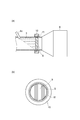
- FIG. 1 is a schematic configuration diagram of an exhaust gas purification device according to the present embodiment. It is an enlarged view of a dispersion device periphery, (a) is a sectional side view, (b) is a front view.
- 2A is an enlarged view of the vicinity of the adhesive material in the side sectional view of FIG. 2A
- FIG. 2A is a case where the contact surface is a planar shape
- FIG. 2B is a case where the contact surface is a rectangular uneven shape
- c) is the case where the heating part case is formed of a contact material and the contact surface is a flat shape
- (d) is the case where the heating part case is formed of a contact material and the contact surface is a rectangular uneven shape.
- (E) is a case where the case of the heating part is formed of an adhesive material and a vacuum double tube, and the contact surface is planar. It is the figure which showed the heating part arrange
- the exhaust gas purifying apparatus according to the present invention is applied to an exhaust gas purifying apparatus provided in an exhaust system of a vehicle engine (internal combustion engine).
- the exhaust gas purifying apparatus according to the present embodiment is an apparatus that purifies harmful substances (environmental pollutants) contained in exhaust gas discharged from an engine (particularly a diesel engine).
- the exhaust gas purifying apparatus according to the present embodiment includes a catalyst oxidation catalyst, SCR [Selective Catalytic Reduction], an NH3 slip catalyst, and a filter DPF [Diesel Particulate Filter].
- the exhaust gas purifying apparatus also includes a reducing agent supply device that supplies a reducing agent (urea water) and a dispersing device that disperses the reducing agent, where the SCR is urea SCR. Furthermore, the exhaust gas purification apparatus according to the present embodiment also includes a heating device that heats the dispersion device disposed in the exhaust pipe.
- a reducing agent supply device that supplies a reducing agent (urea water)
- a dispersing device that disperses the reducing agent, where the SCR is urea SCR.
- the exhaust gas purification apparatus also includes a heating device that heats the dispersion device disposed in the exhaust pipe.
- FIG. 1 is a schematic configuration diagram of an exhaust gas purifying apparatus according to the present embodiment.
- 2A and 2B are enlarged views of the periphery of the dispersing device, where FIG. 2A is a side sectional view (note that only the upstream side of the SCR is a sectional view), and FIG. 2B is a front view.
- the exhaust gas purification device 1 includes an oxidation catalyst 4, a diesel exhaust particulate removal filter (DPF) 5, a selective reduction catalyst (SCR) 6 from the upstream side to the downstream side of the exhaust pipe 3 connected to the exhaust side of the engine 2. And a NH 3 slip catalyst 7, and a reducing agent supply device 8 and a dispersion device 9 for SCR 6.
- DPF diesel exhaust particulate removal filter
- SCR selective reduction catalyst
- the oxidation catalyst 4 is a catalyst that oxidizes HC, CO and the like contained in the exhaust gas.
- the DPF 5 is a filter that collects and removes PM contained in the exhaust gas.
- the SCR 6 is a catalyst that reduces and purifies NOx by chemically reacting ammonia (NH 3 ) hydrolyzed from urea water as a reducing agent and NOx contained in the exhaust gas.
- the NH3 slip catalyst 7 is a catalyst that oxidizes ammonia that has passed through the SCR 6 and has flowed downstream.
- the reducing agent supply device 8 is a device for supplying urea water (reducing agent) to the upstream side of the SCR 6 in the exhaust pipe 3 (in particular, upstream side of the dispersing device 9).
- the reducing agent supply device 8 includes a pump (not shown), a reducing agent tank 8a, a reducing agent introduction pipe 8b, an injector 8c, and the like.
- the reducing agent tank 8a is a tank that stores urea water as a reducing agent. When the pump is activated, urea water is sent from the reducing agent tank 8a to the reducing agent introduction pipe 8b.
- the reducing agent introduction pipe 8b is a pipe that connects the reducing agent tank 8a and the injector 8c and moves urea water from the reducing agent tank 8a to the injector 8c.
- the injector 8 c is disposed between the DPF 5 and the SCR 6 in the exhaust pipe 3 (particularly on the upstream side of the dispersion device 9), and injects urea water into the exhaust pipe 3.
- the urea water injected into the exhaust pipe 3 is uniformly dispersed by the dispersing device 9 and hydrolyzed at a high temperature to become ammonia.
- the dispersion device 9 is a device for dispersing urea water (particularly, hydrolyzed ammonia) supplied into the exhaust pipe 3 by the reducing agent supply device 8 and uniformly introducing it into the SCR 6.
- the dispersing device 9 is disposed between the DPF 5 and the SCR 6 in the exhaust pipe 3 (particularly, downstream of the injector 8c).
- the dispersing device 9 has a disk shape having a predetermined thickness, and is disposed in a state of being fitted in the exhaust pipe 3.
- the structure for dispersing the urea water in the dispersion device 9 is a conventionally known structure such as a mixer or a swirler.
- a dispersion promoting material such as Al 2 O 3 , SiO 3 , TiO 2 or polysilazane may be added to the dispersing device 9.
- the dispersion device 9 is preferably formed of a metal with good thermal conductivity.
- the exhaust gas purification device 1 is provided with a heating device (heating device in FIG. 1 or the like) at an outer peripheral portion (a portion where heating is required) of the exhaust pipe 3 where the dispersion device 9 is disposed in order to heat the dispersion device 9. Only the heating unit 10 is shown).
- the exhaust gas purification device 1 is provided with a temperature sensor that detects the temperature of the exhaust gas discharged from the engine 2.
- the heating device is a device that heats the dispersion device 9 via the exhaust pipe 3.
- any heating device can be applied as long as it can be heated through the exhaust pipe 3, for example, a heat storage device using reaction heat of a chemical reaction.
- the heating device includes a heating unit 10 and the like. As shown in FIG. 2, the heating unit 10 has an annular shape (annular shape in which the diameter of the inner peripheral surface is slightly longer than the diameter of the outer peripheral surface of the exhaust pipe 3) having a predetermined thickness, and the dispersing device 9 is disposed.
- the exhaust pipe 3 is disposed on the entire circumference along the outer peripheral surface of the portion. There is a gap between the inner peripheral surface of the heating unit 10 and the outer peripheral surface of the exhaust pipe 3. The heating unit 10 generates heat and heats the dispersion device 9 from the outside of the exhaust pipe 3.
- the heating device is a chemical heat storage device
- a storage unit that stores a reaction medium of a chemical reaction such as ammonia or water
- a reaction unit that has a reaction material that chemically reacts with the reaction medium
- a reaction medium that includes a storage unit and a reaction unit. It has a supply part etc. to move between.
- This reaction unit corresponds to the heating unit 10 described above, and a reaction material such as MgCl 2 or CaCl 2 is accommodated in a case formed of stainless steel or the like.
- the reaction medium in the storage unit is supplied to the reaction unit by the supply unit, and the reaction unit (heating unit 10) ), The supplied reaction medium and the reaction material chemically react to generate heat.
- the heating unit When the heating unit is disposed in direct contact with the outer peripheral surface of the exhaust pipe, the adhesion between the heating unit and the exhaust pipe decreases due to thermal expansion, vibration, aging, and the like. Therefore, the heat transfer efficiency of the heat generated in the heating unit to the exhaust pipe (and thus the dispersion device) decreases, and the dispersion device cannot be efficiently heated. Therefore, in the exhaust gas purification device 1, in order to prevent the heat transfer efficiency from the heating unit 10 to the exhaust pipe 3 (and thus the dispersion device 9) from being lowered, the exhaust gas purification device 1 is closely attached between the exhaust pipe 3 and the heating unit 10. A material 11 is provided.
- the close contact material 11 is a member that is provided in a gap between the heating unit 10 and the exhaust pipe 3 and that closely contacts the heating unit 10 and the exhaust pipe 3. As shown in FIG. 2, the adhesion material 11 is sandwiched between the inner peripheral surface of the heating unit 10 and the outer peripheral surface of the exhaust pipe 3, and is disposed at the location of the exhaust pipe 3 where the dispersing device 9 is disposed. It is provided on the entire circumference along the outer peripheral surface. Therefore, the adhesion material 11 also has a very thin annular shape.
- the contact material 11 is interposed between the heating unit 10 and the exhaust pipe 3, so that the heating unit 10, the exhaust pipe 3, and the dispersing device 9 can be in close contact with each other even if there is thermal expansion, vibration, aging deterioration, or the like. Since the adhesion between the heating unit 10 and the exhaust pipe 3 can be maintained via the material 11, the heat transfer efficiency from the heating unit 10 to the exhaust pipe 3 (and thus the dispersion device 9) does not decrease. As a result, the heating efficiency with respect to the dispersing device 9 by the heating unit 10 does not decrease, and heat loss can be prevented.
- a material having superelasticity and capable of easily changing its shape is used, for example, a shape memory alloy or a shape memory polymer having a shape memory effect.
- Ni-Ti ⁇ 55% Ni
- a material having high thermal conductivity is desirable.
- the thermal conductivity is 12.1 W / m / K.
- the heating unit 10 is a reaction unit of the chemical heat storage device, and is made of a case and a reaction material accommodated in the case.
- 3A and 3B are enlarged views of the vicinity of the adhesion material in the side sectional view of FIG. 2A, where FIG. 3A is a case where the contact surface is a planar shape, and FIG. 3B is a case where the contact surface is a rectangular uneven shape.
- (C) is a case where the case of the heating part is formed of an adhesive material and the contact surface is a flat shape
- (d) is a case where the case of the heating part is formed of an adhesive material and the contact surface is a rectangular uneven shape
- (E) is a case where the case of the heating part is formed of an adhesive material and a vacuum double tube, and the contact surface has a planar shape.
- the heating unit 10A houses a reaction material in the case 10Aa.
- Case 10Aa is formed with stainless steel etc., and the surface (inner peripheral surface) by the side of adhesion material 11A is a plane shape.
- the exhaust pipe 3A around the place where the dispersing device 9 is disposed has a flat surface on the surface (outer peripheral surface) on the adhesion material 11A side. Therefore, the contact material 11A sandwiched in the gap between the inner peripheral surface of the case 10Aa and the outer peripheral surface of the exhaust pipe 3A has a rectangular shape with a long and narrow cross-sectional shape along the longitudinal direction of the exhaust pipe 3A.
- the heating unit 10B houses the reaction material in the case 10Ba.
- the case 10Ba is made of stainless steel or the like, and has a concave-convex shape (comb shape) whose surface (inner peripheral surface) on the adhesion material 11B side is rectangular.
- the exhaust pipe 3B around the location where the dispersing device 9 is disposed has a rectangular uneven shape in which the surface (outer peripheral surface) on the contact material 11B side engages with the rectangular uneven shape of the case 10Ba via the contact material 11B. is there.
- the contact material 11B sandwiched in the gap between the inner peripheral surface of the case 10Ba and the outer peripheral surface of the exhaust pipe 3B has a thin concavo-convex shape with a rectangular cross-sectional shape along the longitudinal direction of the exhaust pipe 3B.
- case 10C of heating parts have accommodated the reactive material in case 10Ca.
- the case 10Ca is entirely formed of a shape memory alloy or a shape memory polymer, and the exhaust pipe 3C side surface (inner peripheral surface) has a planar shape.
- the surface (outer peripheral surface) on the heating unit 10C side has a planar shape.
- the case 10Ca of the heating unit 10C is formed of a shape memory alloy or a shape memory polymer
- the surface (inner peripheral surface) on the exhaust pipe 3C side of the case 10Ca functions as the adhesion material 11C.
- the adhesion material 11C has a rectangular shape with a long and narrow cross-sectional shape along the longitudinal direction of the exhaust pipe 3C.
- the heating unit 10D stores a reaction material in the case 10Da.
- the entire case 10Da is formed of a shape memory alloy or a shape memory polymer, and the exhaust pipe 3D side surface (inner peripheral surface) has a rectangular uneven shape.
- the exhaust pipe 3D around the location where the dispersing device 9 is disposed has a rectangular uneven shape in which the surface (outer peripheral surface) on the heating unit 10D side engages with the rectangular uneven shape of the case 10Da.
- the surface (inner peripheral surface) on the exhaust pipe 3D side of the case 10Da also functions as the adhesion material 11D.
- the adhesion material 11D has a thin uneven shape with a rectangular cross-sectional shape along the longitudinal direction of the exhaust pipe 3D. As described above, by making the case 10Da function as the adhesion material 11D and having the rectangular uneven shape, the adhesion is improved, the heat transfer distance is shortened, the contact area is increased, and the heating unit is increased. 10D is not displaced in the longitudinal direction of the exhaust pipe 3D.
- the heating unit 10E stores a reaction material in the case 10Ea.
- the surface (inner peripheral surface) on the exhaust pipe 3E side is formed of a shape memory alloy or a shape memory polymer, and the other surface is formed of a vacuum double pipe.
- the circumferential surface is a planar shape.
- the exhaust pipe 3E around the location where the dispersing device 9 is disposed has a planar shape on the heating unit 10E side (outer peripheral surface).
- the surface (inner peripheral surface) on the exhaust pipe 3E side of the case 10Ea of the heating unit 10E is formed of a shape memory alloy or a shape memory polymer
- the surface (inner peripheral surface) on the exhaust pipe 3E side serves as the adhesion material 11E.
- the adhesion material 11E has a rectangular shape with a long and narrow cross-sectional shape along the longitudinal direction of the exhaust pipe 3E.
- each shape around the contact material 11E may be a rectangular uneven shape instead of a planar shape.
- the contact material 11 is provided between the exhaust pipe 3 and the heating unit 10 where the dispersing device 9 is disposed, thereby causing thermal expansion, vibration, deterioration over time, and the like. Even so, it is possible to prevent a decrease in heat transfer efficiency from the heating unit 10 to the exhaust pipe 3 (and thus the dispersion device 9), and to efficiently transfer the heat generated in the heating unit 10 to the dispersion device 9. As a result, the heating efficiency with respect to the dispersing device 9 by the heating unit 10 does not decrease, and heat loss can be prevented. Therefore, the hydrolyzability of urea water can be improved from when the exhaust gas temperature is low, such as immediately after the engine 2 is started. As a result, the NOx purification rate in the SCR 6 can be increased, and the NOx purification performance is improved.
- the adhesion material 11 is provided on the entire circumference along the outer circumferential surface of the exhaust pipe 3, adhesion can be improved and heat transfer efficiency can be improved. Furthermore, the assembly structure of the adhesive material 11 is simplified, and the assembly work is facilitated.
- the contact area is increased and the heat transfer effect can be improved by making the portion where the adhesion material 11 is provided a rectangular uneven shape.
- the heating efficiency for the dispersing device 9 by the heating unit 10 is improved, and heat loss can be further prevented.
- the rectangular uneven shape is provided along the longitudinal direction of the exhaust pipe 3, so that the heating unit 10 is displaced from the disposition position of the dispersing device 9 in the longitudinal direction of the exhaust pipe 3. Therefore, the dispersing device 9 can be reliably heated by the heating unit 10.
- the heating unit 10 is disposed along the outer periphery of the exhaust pipe 3 where the dispersion device 9 is disposed.
- Other locations such as various catalysts and locations upstream of the various catalysts in the exhaust pipe may be used as the locations to be heated in the apparatus 1.
- the heating unit 10 may be disposed on at least one of the oxidation catalyst 4, the SCR 6, and the NH 3 slip catalyst 7 shown in FIG.
- FIG. 4 shows an example in which the heating unit 10 is disposed on the oxidation catalyst 4.
- the oxidation catalyst 4 is provided with a disk-shaped oxidation catalyst 9 ⁇ / b> A having a predetermined thickness in a state of being fitted in the exhaust pipe 3.
- the heating part 10 of the structure same or equivalent to the heating part mentioned above is arrange
- the above-described adhesion material 11 is provided between the exhaust pipe 3 and the heating unit 10.
- the adhesion between the heating unit 10 and the exhaust pipe 3 is maintained via the adhesion material 11, and a reduction in the efficiency of heat transfer from the heating unit 10 to the exhaust pipe 3 (and thus the disc-shaped oxidation catalyst 9 ⁇ / b> A) is prevented. Is done.
- the oxidation catalyst 4 can be heated to the activation temperature at an early stage when the engine is started. Note that the same effect can be obtained when the heating unit 10 is provided in the SCR 6 or the NH 3 slip catalyst 7.
- the heating unit 10 may be disposed in an exhaust pipe at a location where a gas warm-up member that performs heat exchange with the exhaust gas is disposed.
- a gas warm-up member that performs heat exchange with the exhaust gas is disposed.
- FIG. 5 an example in which the heating unit 10 is disposed on the gas warm-up member 9B of the exhaust pipe 3 upstream of the oxidation catalyst 4 is shown in FIG.
- the gas warm-up member 9 ⁇ / b> B has a disk shape having a predetermined thickness, and is disposed in a state of being fitted in the exhaust pipe 3.
- a honeycomb metal honeycomb, metalized honeycomb, ceramic honeycomb, etc.
- the heating part 10 of the structure same or equivalent to the heating part mentioned above is arrange
- the above-described adhesion material 11 is provided between the exhaust pipe 3 and the heating unit 10. Therefore, the adhesion between the heating unit 10 and the exhaust pipe 3 is maintained via the adhesion material 11, and a reduction in heat transfer efficiency from the heating unit 10 to the exhaust pipe 3 (and hence the gas warm-up member 9B) is prevented. Is done.
- the heating unit 10 in the exhaust pipe 3 in which the gas warm-up member 9B is disposed, the catalyst (oxidation catalyst 4) disposed downstream of the gas warm-up member 9B at the time of engine start or the like. Etc.) can be heated to the activation temperature early.
- the gas warm-up member 9B heated by the heating unit 10 is provided in the exhaust pipe 3 upstream of the oxidation catalyst 4, so that the temperature of the catalyst other than the oxidation catalyst 4 (DPF5, SCR6, NH3 slip catalyst 7) can be increased. However, if necessary, it may be provided in the exhaust pipe 3 immediately upstream of the SCR 6 or the NH 3 slip catalyst 7.
- the present invention is applied to an exhaust gas purification device including an oxidation catalyst as a catalyst, an SCR and NH 3 slip catalyst, and a DPF as a filter, but can be applied to exhaust gas purification devices having various other configurations.
- the heating unit and the adhesion material are arranged along the outer circumferential surface of the exhaust pipe along the entire circumference (annular). However, depending on the structure of the heating target, the heating unit and the adhesion material are arranged along the outer circumferential surface. It does not have to be the entire circumference, such as being arranged at a predetermined interval or arranged on a part of the outer peripheral surface.
- the concave / convex shape around the adhesion material is a rectangular concave / convex shape, but may be another concave / convex shape such as a triangular shape or a wave shape.
- the uneven shape is provided along the longitudinal direction of the exhaust pipe.
- the uneven shape may be provided along the circumferential direction of the exhaust pipe.
- the shape memory alloy or shape memory polymer is used as the material of the adhesion material.
- an elastic body having thermal conductivity such as silicon rubber is used, or the thermal conductivity such as silicon grease is used together with the shape memory alloy. It is also possible to use additional grease.
Landscapes
- Chemical & Material Sciences (AREA)
- Engineering & Computer Science (AREA)
- Chemical Kinetics & Catalysis (AREA)
- Health & Medical Sciences (AREA)
- Toxicology (AREA)
- Combustion & Propulsion (AREA)
- Mechanical Engineering (AREA)
- General Engineering & Computer Science (AREA)
- Exhaust Gas After Treatment (AREA)
Description
本発明は、内燃機関から排出される排気ガスを浄化する排気ガス浄化装置において加熱が必要な箇所に配設された加熱部を有するものに関する。
車両の排気ガス浄化装置には、エンジンから排出される排気ガスに含まれる環境汚染物質(HC、CO、NOx等)を浄化するために、排気管には触媒や触媒に添加する還元剤の分散装置等が設けられている。触媒には浄化能力を活性化するための最適温度(活性温度)があるが、エンジン始動時には排気ガスの温度が低く、活性温度に達するまでに時間を要する。そこで、排気ガス浄化装置には、加熱装置によって触媒を暖機しているものがある。特許文献1には、化学反応の反応熱を利用した蓄熱装置によって触媒を暖機する触媒暖機装置が開示されている。また、還元剤として尿素水を用いた場合、尿素水の加水分解性を高めるために、排気ガス浄化装置には加熱装置によって分散装置を加熱しているものがある。
上記したような加熱装置の加熱部を排気管の外周面等に設けるが、熱膨張、振動、経年劣化等によって、加熱部と排気管の外周面等との密着性が低下する場合がある。このような場合、加熱部からの熱伝達効率が低下して、加熱効率が低下し、加熱部からの熱をロスする。
そこで、本発明は、加熱部からの熱伝達効率の低下を防止する排気ガス浄化装置を提供することを課題とする。
本発明に係る排気ガス浄化装置は、内燃機関から排出される排気ガスを浄化する排気ガス浄化装置であって、排気ガス浄化装置において加熱が必要な箇所に配設された加熱部と、加熱が必要な箇所と前記加熱部との間に設けられた密着材とを備えることを特徴とする。
この排気ガス浄化装置には、加熱が必要な箇所に加熱部が配設されている。加熱が必要な箇所としては、例えば、排気管に配設される各種触媒、各種触媒が配設される排気管の上流側の箇所、分散装置の配設される排気管の箇所がある。そして、この排気ガス浄化装置では、その加熱が必要な箇所と加熱部との間に密着材が設けられている。この密着材により、加熱が必要な箇所と加熱部とが密着材を介して常時密着する。そのため、加熱が必要な箇所や加熱部が、熱膨張、振動、経年劣化等しても、加熱が必要な箇所と加熱部とが密着材を介して密着した状態を維持できる。その結果、加熱部から加熱が必要な箇所への熱伝達効率が低下しない。このように、この排気ガス浄化装置は、加熱が必要な箇所と加熱部との間に密着材を設けることにより、加熱部からの熱伝達効率の低下を防止できる。その結果、加熱部による加熱効率が低下せず、熱ロスを防止できる。
本発明の上記排気ガス浄化装置では、密着材は、加熱が必要な箇所の外周面に沿って全周に設けられると好適である。このように、この排気ガス浄化装置では、密着材を加熱が必要な箇所の外周面に沿って全周に設けることにより、加熱部から加熱が必要な箇所への熱伝達効率が向上し、密着材の組付構造が簡易となり、組付作業も容易となる。
本発明の上記排気ガス浄化装置では、加熱部における密着材側の面と加熱が必要な箇所における密着材側の面とは、密着材を介して係合する凹凸形状を有すると好適である。
加熱部における密着材側の面は、凹凸形状を有している。また、加熱が必要な箇所における密着材側の面も、凹凸形状を有している。そして、その加熱部における凹凸形状の面と加熱が必要な箇所における凹凸形状の面との間に密着材が設けられ、密着材を介して加熱部と加熱が必要な箇所とが凹凸形状で係合している。凹凸形状としては、例えば、矩形の凹凸形状、三角形の凹凸形状、波状の凹凸形状がある。このように、凹凸形状とすることにより、密着材を介して加熱部と加熱が必要な箇所との接触面積が大きくなるので、熱伝達効率が向上する。また、凹凸形状とすることにより、加熱が必要な箇所に対する加熱部の位置ズレを防止でき、加熱部で確実に加熱が必要な箇所を加熱できる。このように、この排気ガス浄化装置は、密着材を設ける箇所を凹凸形状とすることにより、熱伝達効力を向上させることができる。
本発明の上記排気ガス浄化装置では、加熱部のケースの全面又はケースにおける加熱が必要な箇所側の面を少なくとも含む一部の面を密着材で形成する構成としてもよい。
加熱部は、ケースで収納されており、このケースの全面又は加熱が必要な箇所側の面を含む一部の面が密着材で形成されている。このように加熱部を形成することにより、加熱部を加熱が必要な箇所に配設することにより、加熱が必要な箇所との間に加熱部の一部によって密着材が設けられることになる。このように、この排気ガス浄化装置は、加熱部のケースの全面又は一部の面を密着材で形成することにより、密着性が向上するとともに、加熱部から加熱が必要な箇所への熱伝達距離を短縮できる。
本発明によれば、加熱が必要な箇所と加熱部との間に密着材を設けることにより、加熱部からの熱伝達効率の低下を防止でき、熱ロスを防止できる。
以下、図面を参照して、本発明に係る排気ガス浄化装置の実施の形態を説明する。なお、各図において同一又は相当する要素については同一の符号を付し、重複する説明を省略する。
本実施の形態では、本発明に係る排気ガス浄化装置を、車両のエンジン(内燃機関)の排気系に設けられる排気ガス浄化装置に適用する。本実施の形態に係る排気ガス浄化装置は、エンジン(特に、ディーゼルエンジン)から排出される排気ガス中に含まれる有害物質(環境汚染物質)を浄化する装置である。本実施の形態に係る排気ガス浄化装置は、触媒の酸化触媒、SCR[Selective Catalytic Reduction]とNH3スリップ触媒及びフィルタのDPF[Diesel Particulate Filter]を備えている。また、本実施の形態に係る排気ガス浄化装置は、SCRが尿素SCRであり、還元剤(尿素水)を供給する還元剤供給装置及びその還元剤を分散する分散装置も備えている。さらに、本実施の形態に係る排気ガス浄化装置は、排気管内に配設される分散装置を加熱する加熱装置も備えている。
図1及び図2を参照して、本実施の形態に係る排気ガス浄化装置1について説明する。図1は、本実施の形態に係る排気ガス浄化装置の概略構成図である。図2は、分散装置周辺の拡大図であり、(a)が側断面図(なお、SCRより上流側のみ断面図としている)であり、(b)が正面図である。
排気ガス浄化装置1は、エンジン2の排気側に接続された排気管3の上流側から下流側に向けて、酸化触媒4、ディーゼル排気微粒子除去フィルタ(DPF)5、選択還元触媒(SCR)6及びNH3スリップ触媒7を有しており、SCR6用の還元剤供給装置8及び分散装置9を有している。
酸化触媒4は、排気ガス中に含まれるHCやCO等を酸化する触媒である。DPF5は、排気ガス中に含まれるPMを捕集して取り除くフィルタである。SCR6は、還元剤である尿素水から加水分解されたアンモニア(NH3)と排気ガス中に含まれるNOxとを化学反応させることによって、NOxを還元して浄化する触媒である。NH3スリップ触媒7は、SCR6をすり抜けて下流側に流れたアンモニアを酸化する触媒である。
還元剤供給装置8は、排気管3におけるSCR6の上流(特に、分散装置9の上流側)に尿素水(還元剤)を供給するための装置である。具体的には、還元剤供給装置8は、ポンプ(図示せず)、還元剤タンク8a、還元剤導入配管8b、インジェクタ8c等を備えている。還元剤タンク8aは、還元剤としての尿素水を貯蔵するタンクである。ポンプが作動すると、還元剤タンク8aから尿素水が還元剤導入配管8bに送り出される。還元剤導入配管8bは、還元剤タンク8aとインジェクタ8cとを接続し、還元剤タンク8aからインジェクタ8cまで尿素水を移動させる配管である。インジェクタ8cは、排気管3におけるDPF5とSCR6との間(特に、分散装置9の上流側)に配設され、排気管3内に尿素水を噴射する。排気管3内に噴射された尿素水は、分散装置9で均一に分散され、高温下で加水分解し、アンモニアになる。
分散装置9は、還元剤供給装置8によって排気管3内に供給された尿素水(特に、加水分解したアンモニア)を分散し、均一にSCR6に導入させるための装置である。分散装置9は、排気管3におけるDPF5とSCR6との間(特に、インジェクタ8cの下流側)に配設される。分散装置9は、図2に示すように、所定の厚さを有する円盤状であり、排気管3内に嵌合した状態で配設される。分散装置9における尿素水を分散させる構造は、ミキサ、スワラ等の従来の周知の構造である。分散装置9には、尿素水の加水分解を促進するために、Al2O3、SiO3、TiO2、ポリシラザン等の加水分解促進材を付加してもよい。また、分散装置9は、加熱部10からの熱の熱伝導性を向上させるために、熱伝導性のよい金属で形成されるとよい。
尿素水は、高温下で加水分解性が高くなり、アンモニアになり易くなる。しかし、エンジン2の始動直後などは、エンジン2から排出された直後の排気ガスの温度は100℃程度と比較的低温である。エンジン2の始動直後などでも、尿素水の加水分解性を高くするために、排気管3内の排気ガス中に噴射された尿素水の温度を高くする必要がある。そこで、排気ガス浄化装置1は、分散装置9を加熱するために、分散装置9が配設される排気管3の外周箇所(加熱が必要な箇所)に加熱装置(図1等では、加熱装置の加熱部10だけを示している)を配設している。なお、排気ガス浄化装置1には、エンジン2から排出された排気ガスの温度を検出する温度センサが設けられている。
加熱装置は、排気管3を介して分散装置9を加熱する装置である。加熱装置としては、排気管3を介して加熱できるものであればどのような加熱装置でも適用可能であり、例えば、化学反応の反応熱を利用した蓄熱装置である。加熱装置は、加熱部10等を有している。加熱部10は、図2に示すように、所定の厚さを有する環状(内周面の直径が排気管3の外周面の直径より若干長い環状)であり、分散装置9が配設される排気管3の箇所の外周面に沿って全周に配設される。加熱部10の内周面と排気管3の外周面との間には、隙間がある。加熱部10は、熱を発生し、排気管3の外側から分散装置9を加熱する。
例えば、加熱装置が化学蓄熱装置の場合、アンモニアや水等の化学反応の反応媒体を貯蔵する貯蔵部、反応媒体と化学反応する反応材を有する反応部、反応媒体を貯蔵部と反応部との間で移動させる供給部等を有している。この反応部が、上記の加熱部10に相当し、ステンレス等で形成されたケースにMgCl2、CaCl2等の反応材を収納している。上記した温度センサで検出された排気ガスの温度が所定温度より低いときに(例えば、エンジン2の始動直後)、供給部によって貯蔵部の反応媒体が反応部に供給され、反応部(加熱部10)でその供給された反応媒体と反応材とが化学反応して、熱を発生する。
なお、加熱部を排気管の外周面に直接接触させた状態で配設した場合、熱膨張、振動や経年劣化等によって、加熱部と排気管との密着性が低下する。そのため、加熱部で発生した熱の排気管(ひいては、分散装置)への熱伝達効率が低下し、分散装置を効率的に加熱できない。そこで、排気ガス浄化装置1では、加熱部10から排気管3(ひいては、分散装置9)への熱伝達効率が低下するのを防止するために、排気管3と加熱部10との間に密着材11を設けている。
密着材11は、加熱部10と排気管3との隙間に設けられ、加熱部10と排気管3とを密着させるための部材である。密着材11は、図2に示すように、加熱部10の内周面と排気管3の外周面との間に挟み込まれた状態で、分散装置9が配設される排気管3の箇所の外周面に沿って全周に設けられる。したがって、密着材11も、非常に薄い環状となる。このように、加熱部10と排気管3との間に密着材11を介在させることにより、加熱部10、排気管3や分散装置9において熱膨張、振動、経年劣化等があっても、密着材11を介して加熱部10と排気管3との間の密着性を維持できるので、加熱部10から排気管3(ひいては、分散装置9)への熱伝達効率が低下しない。その結果、加熱部10による分散装置9に対する加熱効率が低下せず、熱ロスを防止できる。
密着材11の材料としては、超弾性を持ち、容易に形状を変えることができる材料が用いられ、例えば、形状記憶効果のある形状記憶合金や形状記憶ポリマである。このような材料としては、例えば、チタンニッケル合金、鉄―マンガン、Ag-Cd 44/49 at.% Cd、Ag-Cd 46.5/50
at.% Cd、Cu-Al-Ni 14/14.5 wt.% Al and 3/4.5 wt.% Ni、Cu-Snapprox.
15at.% Sn、Cu-Zn 38.5/41.5 wt.% Zn、Cu-Zn-X (X=Si,Al,Sn)、Fe-Pt approx.
25 at.%Pt、Mn-Cu 5/35 at.% Cu、Fe-Mn-Si、Fe-Ni-Co-Al、Pt alloys、Co-Ni-Al、Co-Ni-Ga、Ni-Fe-Ga、Ti-Pd 混合比率は可変、Ni-Ti(~55% Ni)がある。このような材料の中でも、熱伝導率が高い材料が望ましい。例えば、Ni-Ti(~55% Ni)の場合、熱伝導率は12.1W/m/Kである。
at.% Cd、Cu-Al-Ni 14/14.5 wt.% Al and 3/4.5 wt.% Ni、Cu-Snapprox.
15at.% Sn、Cu-Zn 38.5/41.5 wt.% Zn、Cu-Zn-X (X=Si,Al,Sn)、Fe-Pt approx.
25 at.%Pt、Mn-Cu 5/35 at.% Cu、Fe-Mn-Si、Fe-Ni-Co-Al、Pt alloys、Co-Ni-Al、Co-Ni-Ga、Ni-Fe-Ga、Ti-Pd 混合比率は可変、Ni-Ti(~55% Ni)がある。このような材料の中でも、熱伝導率が高い材料が望ましい。例えば、Ni-Ti(~55% Ni)の場合、熱伝導率は12.1W/m/Kである。
図3を参照して、密着材11及びこの密着材11周辺の排気管3の外周面及び加熱部10の内周面の形状及び加熱部10の構成のバリエーションについて説明する。ここでは、加熱部10は、化学蓄熱装置の反応部とし、ケースとケース内に収納される反応材からなるものとする。図3は、図2(a)の側断面図における密着材周辺の拡大図であり、(a)が接触面が平面形状の場合であり、(b)が接触面が矩形の凹凸形状の場合であり、(c)が加熱部のケースを密着材で形成しかつ接触面が平面形状の場合であり、(d)が加熱部のケースを密着材で形成しかつ接触面が矩形の凹凸形状の場合であり、(e)が加熱部のケースを密着材と真空二重管で形成しかつ接触面が平面形状の場合である。
図3(a)を参照して、接触面が平面形状(基本的な形状)の場合について説明する。加熱部10Aは、ケース10Aa内に反応材を収納している。ケース10Aaは、ステンレス等で形成され、密着材11A側の面(内周面)が平面形状である。分散装置9が配設されている箇所周辺の排気管3Aは、密着材11A側の面(外周面)が平面形状である。したがって、ケース10Aaの内周面と排気管3Aの外周面との隙間に挟み込まれた密着材11Aは、排気管3Aの長手方向に沿った断面形状が長細い矩形状である。
図3(b)を参照して、接触面が矩形の凹凸形状の場合について説明する。加熱部10Bは、ケース10Ba内に反応材を収納している。ケース10Baは、ステンレス等で形成され、密着材11B側の面(内周面)が矩形の凹凸形状(クシ型)である。分散装置9が配設されている箇所周辺の排気管3Bは、密着材11B側の面(外周面)が密着材11Bを介してケース10Baの矩形の凹凸形状に係合する矩形の凹凸形状である。したがって、ケース10Baの内周面と排気管3Bの外周面との隙間に挟み込まれた密着材11Bは、排気管3Bの長手方向に沿った断面形状が矩形の薄い凹凸形状である。このような矩形の凹凸形状とすることにより、密着材11Bを介した加熱部10Bと排気管3Bとの接触面積が増加するとともに、加熱部10Bが排気管3Bの長手方向に位置ズレしない。
図3(c)を参照して、加熱部のケースを密着材で形成しかつ接触面が平面形状の場合について説明する。加熱部10Cは、ケース10Ca内に反応材を収納している。ケース10Caは、全面が形状記憶合金あるいは形状記憶ポリマで形成され、排気管3C側の面(内周面)が平面形状である。分散装置9が配設されている箇所周辺の排気管3Cは、加熱部10C側の面(外周面)が平面形状である。加熱部10Cのケース10Caを形状記憶合金あるいは形状記憶ポリマで形成しているので、ケース10Caの排気管3C側の面(内周面)が密着材11Cとして機能する。この密着材11Cは、排気管3Cの長手方向に沿った断面形状が長細い矩形状である。このようにケース10Caを密着材11Cとして機能させることにより、密着性が向上するとともに、加熱部10Cから排気管3C(ひいては、分散装置9)への熱伝達距離が短くなる。
図3(d)を参照して、加熱部のケースを密着材で形成しかつ接触面が矩形の凹凸形状の場合について説明する。加熱部10Dは、ケース10Da内に反応材を収納している。ケース10Daは、全面が形状記憶合金あるいは形状記憶ポリマで形成され、排気管3D側の面(内周面)が矩形の凹凸形状である。分散装置9が配設されている箇所周辺の排気管3Dは、加熱部10D側の面(外周面)がケース10Daの矩形の凹凸形状に係合する矩形の凹凸形状である。このケース10Daの排気管3D側の面(内周面)も、密着材11Dとして機能する。この密着材11Dは、排気管3Dの長手方向に沿った断面形状が矩形の薄い凹凸形状である。このようにケース10Daを密着材11Dとして機能させかつ矩形の凹凸形状とすることにより、上記と同様に、密着性が向上するとともに熱伝達距離が短くなり、かつ、接触面積が増加するとともに加熱部10Dが排気管3Dの長手方向に位置ズレしない。
図3(e)を参照して、加熱部のケースを密着材と真空二重管で形成しかつ接触面が平面形状の場合について説明する。加熱部10Eは、ケース10Ea内に反応材を収納している。ケース10Eaは、排気管3E側の面(内周面)だけが形状記憶合金あるいは形状記憶ポリマで形成されるとともにそれ以外の面が真空二重管で形成され、排気管3E側の面(内周面)が平面形状である。分散装置9が配設されている箇所周辺の排気管3Eは、加熱部10E側の面(外周面)が平面形状である。加熱部10Eのケース10Eaの排気管3E側の面(内周面)を形状記憶合金あるいは形状記憶ポリマで形成しているので、その排気管3E側の面(内周面)が密着材11Eとして機能する。この密着材11Eは、排気管3Eの長手方向に沿った断面形状が長細い矩形状である。このようにケース10Eaを密着材11Eとして機能させることにより、上記したように、密着性が向上するとともに熱伝達距離が短くなる。さらに、ケース10Eaにおける排気管3Eと接触しない面について真空二重管とすることにより、加熱部10Eで発生する熱を排気管3E(ひいては、分散装置9)の方向に集中させることができ、熱伝達効率が更に向上する。なお、ケース10Eaにおける真空二重管の代わりに、断熱材等で形成してもよい。また、密着材11E周辺の各形状を平面形状ではなく、矩形の凹凸形状としてもよい。
この排気ガス浄化装置1によれば、分散装置9が配設される箇所の排気管3と加熱部10との間に密着材11を設けることにより、熱膨張、振動、経年劣化等があったとしても、加熱部10から排気管3(ひいては、分散装置9)への熱伝達効率の低下を防止でき、加熱部10で発生した熱を分散装置9に効率良く伝達できる。その結果、加熱部10による分散装置9に対する加熱効率が低下せず、熱ロスを防止できる。そのため、エンジン2の始動直後などの排気ガス温度が低いときから、尿素水の加水分解性を高めることができる。その結果、SCR6でのNOx浄化率を高めることができ、NOx浄化性能が向上する。
また、排気ガス浄化装置1によれば、密着材11を排気管3の外周面に沿って全周に設けているので、密着性が向上し、熱伝達効率を向上させることができる。さらに、密着材11の組付構造が簡易となり、組付作業も容易となる。
また、排気ガス浄化装置1によれば、密着材11を設ける箇所を矩形の凹凸形状とすることにより、接触面積が増え、熱伝達効力を向上させることができる。その結果、加熱部10による分散装置9に対する加熱効率が向上し、熱ロスを更に防止できる。さらに、排気ガス浄化装置1によれば、矩形の凹凸形状を排気管3の長手方向に沿って設けることにより、加熱部10が分散装置9の配設位置から排気管3の長手方向に位置ズレするのを防止できるので、加熱部10で確実に分散装置9を加熱できる。
なお、本実施の形態では分散装置9を加熱するために、分散装置9が配設されている箇所の排気管3の外周に沿って加熱部10を配設する構成としたが、排気ガス浄化装置1において加熱する箇所としては各種触媒、排気管における各種触媒の上流側の箇所など、他の箇所でもよい。
すなわち、加熱部10を、図1に示した酸化触媒4、SCR6、NH3スリップ触媒7の少なくともいずれか一つに配設してもよい。例えば、加熱部10を酸化触媒4に配設した例を、図4に示す。図4に示すように、酸化触媒4には、所定の厚さを有する円盤状酸化触媒9Aが、排気管3内に嵌合した状態で配設されている。そして、円盤状酸化触媒9Aを加熱するために、排気管3の外周箇所に、上述した加熱部と同一または同等の構成の加熱部10が配設されている。そして、上述した密着材11が、排気管3と加熱部10との間に設けられている。そのため、密着材11を介して加熱部10と排気管3との間の密着性が維持され、加熱部10から排気管3(ひいては、円盤状酸化触媒9A)への熱伝達効率の低下が防止される。その上、酸化触媒4に加熱部10を配設することで、エンジン始動時等において、酸化触媒4を早期に活性化温度まで加熱することができる。なお、SCR6やNH3スリップ触媒7に加熱部10を配設した場合にも、同様の効果を得ることができる。
また、加熱部10を、排気ガスとの熱交換をおこなうガス暖機部材が配設されている箇所の排気管に配設してもよい。例えば、加熱部10を、酸化触媒4の上流の排気管3のガス暖機部材9Bに配設した例を、図5に示す。図5に示すように、ガス暖機部材9Bは、所定の厚さを有する円盤状を有し、排気管3内に嵌合した状態で配設されている。ガス暖機部材9Bとしては、ハニカム(メタルハニカム、メタライズハニカム、セラミックハニカム等)を用いることができる。そして、ガス暖機部材9Bを加熱するために、排気管3の外周箇所に、上述した加熱部と同一または同等の構成の加熱部10が配設されている。そして、上述した密着材11が、排気管3と加熱部10との間に設けられている。そのため、密着材11を介して加熱部10と排気管3との間の密着性が維持され、加熱部10から排気管3(ひいては、ガス暖機部材9B)への熱伝達効率の低下が防止される。その上、ガス暖機部材9Bが配設された排気管3に加熱部10を配設することで、エンジン始動時等において、ガス暖機部材9Bより下流に配設された触媒(酸化触媒4等)を早期に活性化温度まで加熱することができる。なお、加熱部10により加熱されるガス暖機部材9Bは、酸化触媒4の上流の排気管3に設けることで、酸化触媒4以外の触媒(DPF5、SCR6、NH3スリップ触媒7)の昇温が図られるため効率が良いが、必要に応じて、SCR6やNH3スリップ触媒7のすぐ上流の排気管3に設けてもよい。
以上、本発明に係る実施の形態について説明したが、本発明は上記実施の形態に限定されることなく様々な形態で実施される。
例えば、本実施の形態では触媒として酸化触媒、SCRとNH3スリップ触媒、フィルタとしてDPFを備える排気ガス浄化装置に適用したが、他の様々な構成の排気ガス浄化装置に適用できる。
また、本実施の形態では加熱部及び密着材を排気管の外周面に沿って全周(環状)に配置させたが、加熱対象の構造によっては、加熱部及び密着材を外周面に沿って所定間隔で配置、外周面の一部部分に配置など、全周でなくてもよい。
また、本実施の形態では密着材周辺の凹凸形状として矩形の凹凸形状としたが、三角形状、波形状等の他の形状の凹凸形状でもよい。また、本実施の形態では排気管の長手方向に沿って凹凸形状を設けたが、排気管の円周方向に沿って凹凸形状を設けてもよい。このように凹凸形状を設けた場合は、加熱部の円周方向の回転を防止することができる。
また、本実施の形態では密着材の材料として形状記憶合金や形状記憶ポリマを利用したが、シリコンゴムなど熱伝導性を有する弾性体を用いたり、形状記憶合金などと共にシリコングリースなどの熱伝導性グリースを追加して用いることもできる。
1 排気ガス浄化装置
2 エンジン
3,3A,3B,3C,3D,3E 排気管
4 酸化触媒
5 ディーゼル排気微粒子除去フィルタ(DPF)
6 選択還元触媒(SCR)
7 NH3スリップ触媒
8 還元剤供給装置
8a 還元剤タンク
8b 還元剤導入配管
8c インジェクタ
9 分散装置
10,10A,10B,10C,10D,10E 加熱部
10Aa,10Ba,10Ca,10Da,10Ea ケース
10Eb 真空二重管
11,11A,11B,11C,11D,11E 密着材
2 エンジン
3,3A,3B,3C,3D,3E 排気管
4 酸化触媒
5 ディーゼル排気微粒子除去フィルタ(DPF)
6 選択還元触媒(SCR)
7 NH3スリップ触媒
8 還元剤供給装置
8a 還元剤タンク
8b 還元剤導入配管
8c インジェクタ
9 分散装置
10,10A,10B,10C,10D,10E 加熱部
10Aa,10Ba,10Ca,10Da,10Ea ケース
10Eb 真空二重管
11,11A,11B,11C,11D,11E 密着材
Claims (4)
- 内燃機関から排出される排気ガスを浄化する排気ガス浄化装置であって、
前記排気ガス浄化装置において加熱が必要な箇所に配設された加熱部と、
前記加熱が必要な箇所と前記加熱部との間に設けられた密着材と、
を備えることを特徴とする排気ガス浄化装置。 - 前記密着材は、前記加熱が必要な箇所の外周面に沿って全周に設けられることを特徴とする請求項1に記載の排気ガス浄化装置。
- 前記加熱部における前記密着材側の面と前記加熱が必要な箇所における前記密着材側の面とは、前記密着材を介して係合する凹凸形状を有することを特徴とする請求項1又は請求項2に記載の排気ガス浄化装置。
- 前記加熱部のケースの全面又はケースにおける前記加熱が必要な箇所側の面を少なくとも含む一部の面を密着材で形成することを特徴とする請求項1~請求項3のいずれか1項に記載の排気ガス浄化装置。
Priority Applications (1)
| Application Number | Priority Date | Filing Date | Title |
|---|---|---|---|
| JP2014536751A JP5915762B2 (ja) | 2012-09-18 | 2013-09-06 | 排気ガス浄化装置 |
Applications Claiming Priority (2)
| Application Number | Priority Date | Filing Date | Title |
|---|---|---|---|
| JP2012204728 | 2012-09-18 | ||
| JP2012-204728 | 2012-09-18 |
Publications (1)
| Publication Number | Publication Date |
|---|---|
| WO2014045908A1 true WO2014045908A1 (ja) | 2014-03-27 |
Family
ID=50341223
Family Applications (1)
| Application Number | Title | Priority Date | Filing Date |
|---|---|---|---|
| PCT/JP2013/074128 Ceased WO2014045908A1 (ja) | 2012-09-18 | 2013-09-06 | 排気ガス浄化装置 |
Country Status (2)
| Country | Link |
|---|---|
| JP (1) | JP5915762B2 (ja) |
| WO (1) | WO2014045908A1 (ja) |
Cited By (1)
| Publication number | Priority date | Publication date | Assignee | Title |
|---|---|---|---|---|
| WO2018147369A1 (ja) * | 2017-02-09 | 2018-08-16 | エヌ・イーケムキャット株式会社 | 排ガス浄化装置 |
Citations (3)
| Publication number | Priority date | Publication date | Assignee | Title |
|---|---|---|---|---|
| JPH0932536A (ja) * | 1995-07-17 | 1997-02-04 | Toyota Motor Corp | 通電加熱式触媒の電極構造及びその電極支持ホルダへの絶縁被膜形成方法 |
| JPH11125113A (ja) * | 1997-10-23 | 1999-05-11 | Denso Corp | 内燃機関の排気浄化装置 |
| JP2012021488A (ja) * | 2010-07-15 | 2012-02-02 | Toyota Motor Corp | 電気加熱式触媒装置 |
-
2013
- 2013-09-06 JP JP2014536751A patent/JP5915762B2/ja not_active Expired - Fee Related
- 2013-09-06 WO PCT/JP2013/074128 patent/WO2014045908A1/ja not_active Ceased
Patent Citations (3)
| Publication number | Priority date | Publication date | Assignee | Title |
|---|---|---|---|---|
| JPH0932536A (ja) * | 1995-07-17 | 1997-02-04 | Toyota Motor Corp | 通電加熱式触媒の電極構造及びその電極支持ホルダへの絶縁被膜形成方法 |
| JPH11125113A (ja) * | 1997-10-23 | 1999-05-11 | Denso Corp | 内燃機関の排気浄化装置 |
| JP2012021488A (ja) * | 2010-07-15 | 2012-02-02 | Toyota Motor Corp | 電気加熱式触媒装置 |
Cited By (1)
| Publication number | Priority date | Publication date | Assignee | Title |
|---|---|---|---|---|
| WO2018147369A1 (ja) * | 2017-02-09 | 2018-08-16 | エヌ・イーケムキャット株式会社 | 排ガス浄化装置 |
Also Published As
| Publication number | Publication date |
|---|---|
| JP5915762B2 (ja) | 2016-05-11 |
| JPWO2014045908A1 (ja) | 2016-08-18 |
Similar Documents
| Publication | Publication Date | Title |
|---|---|---|
| US9856774B2 (en) | Engine exhaust system | |
| JP5775503B2 (ja) | 蓄熱装置 | |
| ATE434718T1 (de) | Abgasnachbehandlungssystem | |
| JP5915762B2 (ja) | 排気ガス浄化装置 | |
| JP2013234625A (ja) | 排気浄化装置 | |
| JP5780263B2 (ja) | 化学蓄熱装置 | |
| JP2012117489A (ja) | エンジンの排気浄化装置 | |
| JP2014101869A (ja) | 排気ガス浄化システム | |
| EP2930324A1 (en) | Exhaust emission purifying apparatus | |
| JP2014088816A (ja) | 排気ガス浄化システム | |
| JP6160257B2 (ja) | 排気浄化装置 | |
| JP2014222055A (ja) | 排気ガス浄化システム | |
| JP2021131029A (ja) | 排気浄化装置および車両 | |
| JP5939146B2 (ja) | 触媒担持体及び触媒担持体の製造方法 | |
| JP6136673B2 (ja) | 化学蓄熱用成形体の作製方法及び化学蓄熱装置 | |
| JP2015052442A (ja) | 化学蓄熱装置 | |
| JP2013127209A (ja) | 内燃機関の排気浄化装置 | |
| JP2010013969A (ja) | 排気ガス浄化装置 | |
| JP2020516815A (ja) | 排ガスシステム | |
| JP2014227857A (ja) | 排気ガス浄化システム | |
| JP2014111913A (ja) | 排気浄化装置 | |
| JP2015014217A (ja) | 排ガス浄化装置 | |
| JP2016023868A (ja) | 化学蓄熱装置 | |
| JP2015151887A (ja) | Scrシステム | |
| JP2015001314A (ja) | 化学蓄熱装置 |
Legal Events
| Date | Code | Title | Description |
|---|---|---|---|
| 121 | Ep: the epo has been informed by wipo that ep was designated in this application |
Ref document number: 13838457 Country of ref document: EP Kind code of ref document: A1 |
|
| ENP | Entry into the national phase |
Ref document number: 2014536751 Country of ref document: JP Kind code of ref document: A |
|
| NENP | Non-entry into the national phase |
Ref country code: DE |
|
| 122 | Ep: pct application non-entry in european phase |
Ref document number: 13838457 Country of ref document: EP Kind code of ref document: A1 |