WO2014042202A1 - Appareil de diagnostic par rayons x - Google Patents
Appareil de diagnostic par rayons x Download PDFInfo
- Publication number
- WO2014042202A1 WO2014042202A1 PCT/JP2013/074594 JP2013074594W WO2014042202A1 WO 2014042202 A1 WO2014042202 A1 WO 2014042202A1 JP 2013074594 W JP2013074594 W JP 2013074594W WO 2014042202 A1 WO2014042202 A1 WO 2014042202A1
- Authority
- WO
- WIPO (PCT)
- Prior art keywords
- ray
- image
- region
- diagnostic apparatus
- subject
- Prior art date
Links
- 238000001514 detection method Methods 0.000 claims description 11
- 230000001678 irradiating effect Effects 0.000 claims 1
- 238000007405 data analysis Methods 0.000 description 33
- 210000004204 blood vessel Anatomy 0.000 description 9
- 210000005252 bulbus oculi Anatomy 0.000 description 9
- 238000000034 method Methods 0.000 description 9
- 238000003384 imaging method Methods 0.000 description 7
- 210000000988 bone and bone Anatomy 0.000 description 6
- 239000000523 sample Substances 0.000 description 6
- 238000012545 processing Methods 0.000 description 5
- 230000000007 visual effect Effects 0.000 description 5
- 238000010586 diagram Methods 0.000 description 4
- 238000002594 fluoroscopy Methods 0.000 description 4
- 238000002697 interventional radiology Methods 0.000 description 4
- 230000002093 peripheral effect Effects 0.000 description 4
- 238000010521 absorption reaction Methods 0.000 description 3
- 238000006243 chemical reaction Methods 0.000 description 3
- 210000001685 thyroid gland Anatomy 0.000 description 3
- 230000002238 attenuated effect Effects 0.000 description 2
- 210000004556 brain Anatomy 0.000 description 2
- 239000002872 contrast media Substances 0.000 description 2
- 230000000694 effects Effects 0.000 description 2
- 210000001508 eye Anatomy 0.000 description 2
- 210000003128 head Anatomy 0.000 description 2
- 239000002184 metal Substances 0.000 description 2
- 206010002329 Aneurysm Diseases 0.000 description 1
- 238000012276 Endovascular treatment Methods 0.000 description 1
- 230000002490 cerebral effect Effects 0.000 description 1
- 238000012790 confirmation Methods 0.000 description 1
- 238000013016 damping Methods 0.000 description 1
- 238000013480 data collection Methods 0.000 description 1
- 238000003745 diagnosis Methods 0.000 description 1
- 238000012986 modification Methods 0.000 description 1
- 230000004048 modification Effects 0.000 description 1
- 230000005855 radiation Effects 0.000 description 1
- 239000004065 semiconductor Substances 0.000 description 1
- 230000002194 synthesizing effect Effects 0.000 description 1
- 238000011282 treatment Methods 0.000 description 1
- 238000002604 ultrasonography Methods 0.000 description 1
Images


Classifications
-
- A—HUMAN NECESSITIES
- A61—MEDICAL OR VETERINARY SCIENCE; HYGIENE
- A61B—DIAGNOSIS; SURGERY; IDENTIFICATION
- A61B6/00—Apparatus or devices for radiation diagnosis; Apparatus or devices for radiation diagnosis combined with radiation therapy equipment
- A61B6/54—Control of apparatus or devices for radiation diagnosis
- A61B6/542—Control of apparatus or devices for radiation diagnosis involving control of exposure
-
- A—HUMAN NECESSITIES
- A61—MEDICAL OR VETERINARY SCIENCE; HYGIENE
- A61B—DIAGNOSIS; SURGERY; IDENTIFICATION
- A61B6/00—Apparatus or devices for radiation diagnosis; Apparatus or devices for radiation diagnosis combined with radiation therapy equipment
-
- A—HUMAN NECESSITIES
- A61—MEDICAL OR VETERINARY SCIENCE; HYGIENE
- A61B—DIAGNOSIS; SURGERY; IDENTIFICATION
- A61B6/00—Apparatus or devices for radiation diagnosis; Apparatus or devices for radiation diagnosis combined with radiation therapy equipment
- A61B6/06—Diaphragms
-
- A—HUMAN NECESSITIES
- A61—MEDICAL OR VETERINARY SCIENCE; HYGIENE
- A61B—DIAGNOSIS; SURGERY; IDENTIFICATION
- A61B6/00—Apparatus or devices for radiation diagnosis; Apparatus or devices for radiation diagnosis combined with radiation therapy equipment
- A61B6/10—Safety means specially adapted therefor
-
- A—HUMAN NECESSITIES
- A61—MEDICAL OR VETERINARY SCIENCE; HYGIENE
- A61B—DIAGNOSIS; SURGERY; IDENTIFICATION
- A61B6/00—Apparatus or devices for radiation diagnosis; Apparatus or devices for radiation diagnosis combined with radiation therapy equipment
- A61B6/12—Arrangements for detecting or locating foreign bodies
-
- A—HUMAN NECESSITIES
- A61—MEDICAL OR VETERINARY SCIENCE; HYGIENE
- A61B—DIAGNOSIS; SURGERY; IDENTIFICATION
- A61B6/00—Apparatus or devices for radiation diagnosis; Apparatus or devices for radiation diagnosis combined with radiation therapy equipment
- A61B6/52—Devices using data or image processing specially adapted for radiation diagnosis
- A61B6/5211—Devices using data or image processing specially adapted for radiation diagnosis involving processing of medical diagnostic data
-
- A—HUMAN NECESSITIES
- A61—MEDICAL OR VETERINARY SCIENCE; HYGIENE
- A61B—DIAGNOSIS; SURGERY; IDENTIFICATION
- A61B6/00—Apparatus or devices for radiation diagnosis; Apparatus or devices for radiation diagnosis combined with radiation therapy equipment
- A61B6/54—Control of apparatus or devices for radiation diagnosis
- A61B6/545—Control of apparatus or devices for radiation diagnosis involving automatic set-up of acquisition parameters
-
- G—PHYSICS
- G16—INFORMATION AND COMMUNICATION TECHNOLOGY [ICT] SPECIALLY ADAPTED FOR SPECIFIC APPLICATION FIELDS
- G16H—HEALTHCARE INFORMATICS, i.e. INFORMATION AND COMMUNICATION TECHNOLOGY [ICT] SPECIALLY ADAPTED FOR THE HANDLING OR PROCESSING OF MEDICAL OR HEALTHCARE DATA
- G16H50/00—ICT specially adapted for medical diagnosis, medical simulation or medical data mining; ICT specially adapted for detecting, monitoring or modelling epidemics or pandemics
- G16H50/20—ICT specially adapted for medical diagnosis, medical simulation or medical data mining; ICT specially adapted for detecting, monitoring or modelling epidemics or pandemics for computer-aided diagnosis, e.g. based on medical expert systems
-
- A—HUMAN NECESSITIES
- A61—MEDICAL OR VETERINARY SCIENCE; HYGIENE
- A61B—DIAGNOSIS; SURGERY; IDENTIFICATION
- A61B6/00—Apparatus or devices for radiation diagnosis; Apparatus or devices for radiation diagnosis combined with radiation therapy equipment
- A61B6/40—Arrangements for generating radiation specially adapted for radiation diagnosis
- A61B6/4035—Arrangements for generating radiation specially adapted for radiation diagnosis the source being combined with a filter or grating
-
- A—HUMAN NECESSITIES
- A61—MEDICAL OR VETERINARY SCIENCE; HYGIENE
- A61B—DIAGNOSIS; SURGERY; IDENTIFICATION
- A61B6/00—Apparatus or devices for radiation diagnosis; Apparatus or devices for radiation diagnosis combined with radiation therapy equipment
- A61B6/48—Diagnostic techniques
- A61B6/486—Diagnostic techniques involving generating temporal series of image data
- A61B6/487—Diagnostic techniques involving generating temporal series of image data involving fluoroscopy
Definitions
- Embodiments of the present invention relate to an X-ray diagnostic apparatus.
- aneurysms and clogging of cerebral blood vessels may be treated with a catheter under fluoroscopy with an X-ray diagnostic apparatus.
- IVR interventional radiology
- the amount of X-ray absorption varies depending on the patient's site. For example, parts such as the lens (eyes) and the thyroid gland have high absorption.
- the X-ray conditions for IVR are determined to obtain the information necessary for the catheter procedure. That is, the difference in the amount of absorption depending on the site is not considered in the X-ray conditions of IVR. For this reason, in the case of an X-ray condition in which a long fluoroscopic time is set, there is a concern that highly sensitive parts such as the eyes and the thyroid gland are exposed to high exposure.
- a compensation filter such as a metal plate is inserted into an arbitrary irradiation field to reduce the exposure by attenuating X-rays, and a diaphragm such as a lead plate is used other than the arbitrary irradiation field.
- a technique for inserting and shielding X-rays to prevent exposure is known.
- the compensation filter is originally a filter used for preventing halation and the like, and therefore is not automatically used for reducing exposure.
- the X-ray diagnostic apparatus it is desirable to automatically reduce the exposure of the highly sensitive part of the patient. In addition, it is desirable to reduce the exposure not only to the highly sensitive part of the patient but also to parts such as the hand of the operator at the time of puncture and the hand of the supporter at the time of PPI (percutaneous peripheral intervention).
- PPI percutaneous peripheral intervention
- the objective is to provide an X-ray diagnostic apparatus that can automatically reduce the exposure of a site to be subjected to exposure reduction.
- the X-ray diagnostic apparatus of the embodiment includes X-ray generation means, X-ray detection means, image generation means, display means, part detection means, and attenuation means.
- the X-ray generation means generates X-rays irradiated on the subject.
- the X-ray detection means detects X-rays transmitted through the subject.
- the image generation means generates an X-ray image based on the detected X-ray.
- the display means displays the X-ray image.
- the part detection means detects a part of the exposure reduction target based on the X-ray image.
- the attenuation means attenuates the X-rays irradiated to the area including the detected part.
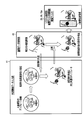
- FIG. 1 is a block diagram of the X-ray diagnostic apparatus according to the first embodiment.
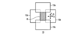
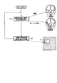
- FIG. 2 is a plan view for explaining a diaphragm blade in the embodiment.
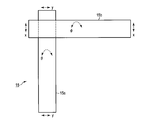
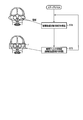
- FIG. 3 is a plan view for explaining a compensation filter in the same embodiment.
- FIG. 4 is a flowchart for explaining the operation in the embodiment.
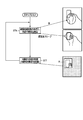
- FIG. 5 is a schematic diagram for explaining the operation in the embodiment.
- FIG. 6 is a schematic diagram for explaining the operation in the embodiment.
- FIG. 7 is a flowchart for explaining the operation of the X-ray diagnostic apparatus according to the second embodiment.
- FIG. 8 is a flowchart for explaining the operation in the embodiment.
- FIG. 9 is a flowchart for explaining the operation of the X-ray diagnostic apparatus according to the third embodiment.
- FIG. 10 is a flowchart for explaining the operation in the embodiment.
- FIG. 1 is a block diagram of the X-ray diagnostic apparatus according to the first embodiment.
- the horizontal width direction of the subject P is the x direction
- the body axis direction of the subject P is the y direction
- the thickness direction of the subject P is the z direction.
- the X-ray diagnostic apparatus 1 includes an X-ray tube 11, an X-ray restrictor 13, a compensation filter unit 15, an X-ray detector 16, a bed 17, and a C arm 19 as a data collection system.
- the C arm 19 is arranged with the X-ray tube 11 and the X-ray detector 16 facing each other.
- the X-ray diagnostic apparatus 1 includes, as a data processing system, a system control unit 25, an operation unit 27, an image generation unit 28, an X-ray controller 29, a high voltage generator 31, an aperture control unit 33, a compensation filter control unit 35, A holding device control unit 37, an external device data input device 41, an image display unit 43, and an image data analysis unit 45 are provided.
- the X-ray tube 11 is a vacuum tube that generates X-rays, and generates X-rays by accelerating electrons with a high voltage from the high-voltage generator 31 and colliding with a target.
- the bed 17 has a mechanism that can be tilted and positioned while the subject P is mounted.
- the X-ray restrictor 13 is provided between the X-ray tube 11 and the subject P, forms an X-ray irradiation region R on the detection surface of the X-ray detector 16, and prevents unnecessary exposure to the subject P. It is an aperture device for preventing.
- the X-ray diaphragm 13 has a plurality of X-ray diaphragm blades 13a to 13d that can move independently so as to limit the irradiation region R of the X-ray irradiated to the subject P to the region of interest. (See FIG. 2). In FIG.
- the x direction and the y direction in which the X-ray diaphragm blades 13a to 13d are movable are directions orthogonal to the X-ray irradiation direction.
- Each of the X-ray diaphragm blades 13a to 13d is formed of lead or the like that shields X-rays.
- the region of interest is set as a region including a predetermined instrument projected on the X-ray image by the image data analysis unit 45.
- the compensation filter unit 15 is a filter that is provided between the X-ray restrictor 13 and the subject P and attenuates the X-rays that are irradiated to the exposure reduction target region, and is a plurality of independently movable compensation filters. 15a and 15b (see FIG. 3).
- Each compensation filter 15a, 15b is formed of a metal plate having a rectangular shape, for example.
- the compensation filters 15a and 15b are arranged so that their longitudinal directions are orthogonal to each other in the initial state, and can be translated in the x direction or the y direction by moving the both ends by an equal distance from each other. It can be rotated in the ⁇ direction or the ⁇ direction by moving it by different distances.
- FIG. 1 is a filter that is provided between the X-ray restrictor 13 and the subject P and attenuates the X-rays that are irradiated to the exposure reduction target region, and is a plurality of independently movable compensation filters. 15a and 15b (see FIG.
- the x direction, the y direction, the ⁇ direction, or the ⁇ direction in which the compensation filters 15a and 15b can move are orthogonal to the X-ray irradiation direction.
- the number of compensation filters 15a and 15b is not limited to two, but may be one or three or more.
- the X-ray detector 16 is a flat detector (FPD) provided with a detection surface facing the X-ray tube 11 through the bed 17.
- the FPD has, for example, a scintillator and a photodiode array, generates electron holes by applying X-rays transmitted through the subject P to the photoelectric film, accumulates them in a semiconductor switch, and reads them as electrical signals. X-ray signals are detected.
- the bed 17 has a mechanism that can be tilted and positioned while the subject P is mounted.
- the system control unit 25 is a central processing unit that performs control related to collection of image data and control related to image processing and image reproduction processing of the collected image data.
- the operation unit 27 includes a keyboard, a mouse, a button, an operation lever, and the like for inputting instructions regarding the setting, deformation, and movement of the X-ray irradiation region R and the exposure reduction region, and specification regarding a highly sensitive region.
- the exposure reduction region means a region on the detection surface of the X-ray detector 16 where X-rays are attenuated by the compensation filters 15a and 15b.
- the image generation unit 28 generates an X-ray image (non-contrast image, contrast image, difference image) based on the X-ray data obtained by the X-ray detector 16.
- the non-contrast image is an X-ray image before contrast agent administration, and is a projection image having a bone image.
- a contrast image is an X-ray image after contrast medium administration, and is a projection image having bone and blood vessel images.
- the difference image is an X-ray image representing a difference between the contrast image and the non-contrast image, and is a projection image having a blood vessel image.
- the difference image can be generated by the image calculation unit 28b calculating the difference between the non-contrast image stored in the image storage unit 28a and the contrast image based on the X-ray data obtained by the X-ray detector 16. ing.
- the X-ray controller 29 controls the high voltage generator 31 that generates a high voltage to be applied to the X-ray tube 11.
- the high voltage generator 31 generates a high voltage based on the control signal supplied from the X-ray controller 29 and supplies it to the X-ray tube 11.
- the diaphragm control unit 33 performs movement control on the X-ray diaphragm blades 13a to 13d in order to set, move, and deform the X-ray irradiation region R.
- the aperture control unit 33 irradiates the region of interest set by the image data analysis unit 45 with X-rays, and each X-ray aperture blade so as to shield the portion detected by the image data analysis unit 45 from the X-rays.
- the movement control of 13a to 13d is performed.
- the X-ray aperture blades 13a to 13d and the aperture control unit 33 constitute attenuation means for attenuating X-rays irradiated to the region including the region detected by the image data analysis unit 45.
- the present invention is not limited to this, and the X-ray aperture blades 13a to 13d constitute attenuation means.
- the aperture controller 33 Attenuates X-rays irradiated to the site. Therefore, a control unit that performs movement control of the attenuation unit for the purpose may be configured.
- the compensation filter control unit 35 performs movement control on the compensation filters 15a and 15b in order to set, deform, and move the exposure reduction region. For example, the compensation filter control unit 35 performs movement control of the compensation filters 15a and 15b so as to cover the part detected by the image data analysis unit 45 from the X-rays. At this time, the compensation filters 15a and 15b and the compensation filter control unit 35 constitute attenuation means for attenuating the X-rays irradiated to the region including the region detected by the image data analysis unit 45. However, the present invention is not limited to this, and the compensation filters 15a and 15b constitute attenuation means. When the compensation filter control unit 35 detects a part, the compensation filter control part 35 attenuates the X-rays irradiated to the part. You may comprise the control part which performs movement control of the said attenuation
- the holding device control unit 37 controls the top plate of the bed 17 in accordance with an instruction from the system control unit 25.
- the X-ray detector control unit 39 controls the operation of the X-ray detector 16.
- the external device data input device 41 a device that provides CT images or a 3D workstation can be used as appropriate.
- the external device data input device 41 sends a CT image to the display data generation unit 43 a and sends a template image to the image data analysis unit 45.
- the CT image is an image obtained by imaging the subject P with a CT apparatus (not shown).
- the template image is a three-dimensional image of a human body model having bone and blood vessel images, or a whole-body projection image for each representative angle.
- the image display unit 43 displays the X-ray image generated by the image generation unit 28, and specifically includes a display data generation unit 43a and a monitor 43b.
- the display data generation unit 43a generates display data including at least the X-ray image generated by the image generation unit 28, and sends the display data to the monitor 43b.
- the display data includes the CT image and the X-ray image generated by the image generation unit 28 when there is a CT image transmitted from the external device data input device 41. That is, it is essential to display the X-ray image generated by the image generation unit 28, but it is not essential to display CT images from other devices.
- the monitor 43b displays the display data received from the display data generation unit 43a.
- the image data analysis unit (part detection means) 45 detects a part to be subjected to exposure reduction based on the X-ray image generated by the image generation unit 28.
- the image data analysis unit 45 includes a storage unit (not shown) that stores a template image that includes a portion that is subject to exposure reduction, and compares the template image with the X-ray image, thereby obtaining an X-ray image. You may detect the site
- the image display unit 43 is located on the display screen almost immediately before the movement control by the aperture control unit 33 or the compensation filter control unit 35 is performed at a location indicating a region including the part detected by the image data analysis unit 45. An X-ray image may be displayed.
- the X-ray image to be compared is a projected image in the visual field direction when the template image is a three-dimensional image of a human body model, and is closest to the representative angle when the template image is a projected image of the whole body. It is an angle projection image.
- a three-dimensional image of the human body model for example, a three-dimensional-head blood vessel X-ray contrast image (a three-dimensional image having a bone and a blood vessel image) can be used as appropriate.
- the whole-body projection image in the template image is a bone projection image when the generated X-ray image is a non-contrast image, and a bone and blood vessel image when the generated X-ray image is a contrast image. If the generated X-ray image is a difference image, it is a projection image of a blood vessel.
- “by comparing” may be read as “by comparing and performing pattern matching”, for example.
- This pattern matching means that a characteristic structure map (the template image described above) is provided and matching with the structure is performed.
- the image data analysis unit 45 estimates the region of the visual field and supports the function (i) or (ii) may be provided.
- C-arm 19 angle obtained from the system control unit 25, position of the bed 17, SID (source-image distance), FOV (field field of view), subject (patient) A function for estimating the position of the subject P and the visual field based on the information (height / weight) and the subject (patient) body position information, and estimating the region of the visual field.
- a site to be reduced in exposure a highly sensitive site such as an eyeball or a thyroid gland and an arbitrary designated site are applicable.
- a part of the hand of the operator at the time of puncture or a part of the supporter's hand at the time of PPT (percutaneous peripheral intervention) can be used as appropriate.
- the exposure reduction target part in the template image is, for example, a range designated on the template image, or another position information (position information on the subject or structure information that can identify laboratory coordinates, Can be specified).
- the image data analysis unit (setting unit) 45 detects a predetermined instrument projected on the X-ray image based on the X-ray image generated by the image generation unit 28, and determines a region of interest including the instrument. It may be set.
- the image data analysis unit 45 includes a storage unit (not shown) that stores a template image representing a predetermined instrument, and compares the template image with the X-ray image to thereby compare the template image with the X-ray image.
- a predetermined instrument may be detected.
- the predetermined instrument for example, a catheter or an ultrasonic probe can be used as appropriate.
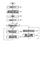
- the operation of the X-ray diagnostic apparatus configured as described above will be described with reference to the flowchart of FIG.
- the image generation unit 28 may generate an X-ray image so that the inside of the X-ray irradiation region R is a moving image and the outside of the X-ray irradiation region R is a still image.
- the X-ray generation unit 28 may generate an X-ray image so that the inside of the exposure reduction region r is a still image and the outside of the exposure reduction region r is a moving image. That is, the image generation unit 28 may generate an X-ray image by synthesizing the current moving image and a still image almost immediately before attenuation by the attenuation unit. Alternatively, the image generation unit 28 may generate an X-ray image by combining the current moving image and a still image almost immediately before the movement control of the X-ray diaphragm blades 13a to 13d or the compensation filters 15a and 15b. . The same applies to the following embodiments.
- an appropriate X-ray condition (tube voltage, tube current, fluoroscopy time) for the subject P by an operator such as a doctor or an engineer. Etc.) is input via the operation unit 27 (step ST1).
- the tube current is set to be small in the fluoroscopic imaging as compared with the main imaging, and is controlled to an appropriate X-ray condition by auto brightness control (ABC).
- ABSC auto brightness control
- the operator selects the control of the X-ray irradiation region R or the control of the exposure reduction region by operating the operation unit 27 (ST2).
- This selection is not limited to directly specifying “control of the X-ray irradiation region R” or “control of the exposure reduction region”, but indirectly by specifying “non-brain” as the X-ray irradiation target.
- a method of selecting “control of the irradiation region R” may be adopted. Note that when “brain” is designated as the X-ray irradiation target, a wide field of view is required, so “control of the exposure reduction region” is selected indirectly.
- Control of X-ray irradiation region R” may be read as “control of X-ray diaphragm blades 13a to 13d”, and “control of exposure reduction region” may be read as “control of compensation filters 15a and 15b”. Good.
- the subject P placed on the bed 17 is irradiated with X-rays from the X-ray tube 11 via the X-ray controller 29 and the high voltage generator 31 (step ST3).
- the X-ray diaphragm blades 13a, 13b, 13c, and 13d of the X-ray diaphragm 13 are controlled by the diaphragm controller 33 so that the X-ray irradiation region R is maximized.
- the compensation filters 15a and 15b of the compensation filter unit 15 are held by the compensation filter control unit 35 at positions where the exposure reduction region is minimized so as not to attenuate the X-ray irradiation.
- an X-ray image is generated and displayed based on the X-ray transmitted through the subject P (step ST4). That is, the X-ray detector 16 detects X-rays that have passed through the subject P and converts them into electrical signals. This conversion may be direct conversion that converts an X-ray to an electric signal, or may be indirect conversion that converts an X-ray to an electric signal via light.
- the electrical signal collected by the X-ray detector 16 is subjected to desired image processing, converted to a TV video signal by the image generation unit 28, and displayed on the image display unit 43 as an X-ray fluoroscopic image.
- the image data analysis unit 45 detects a part to be reduced in exposure and a predetermined instrument from the generated X-ray image according to the selection result of step ST2 (ST5).
- the image data analysis unit 45 detects the exposure reduction target region based on the X-ray image and projects it on the X-ray image.
- a predetermined instrument is detected (ST6), and a region of interest including the instrument is set.
- the image data analysis unit 45 sends the angle of the generated X-ray image (current X-ray contrast image) to the external device data input unit 41, thereby A template image having the same angle and specifying a high-sensitivity part in advance is acquired from the external device data input unit 41.
- the image data analysis unit 45 compares the acquired template image with the X-ray image generated by the image generation unit 28, detects a part to be reduced in exposure by pattern matching of both, and X A predetermined instrument projected on the line image is detected. Further, the image data analysis unit 45 sends part region data indicating a region including the detected region and region of interest data indicating a region of interest to the aperture control unit 33 via the system control unit 25.
- the part area data may vary from person to person in the position and size of the exposure reduction target part, so that the part area data may be an area having an arbitrary margin and the margin can be corrected by the operation of the operation unit 27.
- the part to be reduced in exposure appears in an X-ray image
- the part is designated on the X-ray image
- the outline of the part is drawn with a cursor trace or the like, and separated from the outline by a predetermined interval or more.
- the margin may be adjusted automatically.
- the aperture control unit 33 irradiates the region of interest including the instrument with X-rays based on the region region data and the region-of-interest data, and also blocks each X-ray aperture blade 13a ⁇
- the movement control of 13d is performed (ST7).
- Each of the X-ray diaphragm blades 13a to 13d moves independently so as to limit the X-ray irradiation region R irradiated to the subject P to the region of interest. Thereafter, the X-ray diagnostic apparatus 1 repeatedly executes the processes of steps ST6 to ST7.
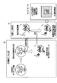
- the image data analysis unit 45 detects the site of the exposure reduction target based on the X-ray image (ST8). Specifically, as shown in FIG. 6, the image data analysis unit 45 compares the template image acquired from the external device data input unit 41 with the X-ray image generated by the image generation unit 28 as described above, The part of the exposure reduction target is detected by pattern matching between them. Further, the image data analysis unit 45 sends part region data indicating a region including the detected part to the compensation filter control unit 35 via the system control unit 25.
- the compensation filter control unit 35 performs movement control of the compensation filter 15a so as to cover the part of the exposure reduction target from the X-ray based on the part region data (ST9).
- the compensation filter 15a moves independently so as to attenuate the X-rays irradiated to the exposure reduction region r.
- the X-ray diagnostic apparatus 1 repeatedly executes the processes of steps ST8 to ST9.
- the X-ray diagnostic apparatus 1 excludes the exposure reduction region r from the estimation of the X-ray condition (the X-ray condition is controlled by the image information of the part excluding the compensation filter position). The same applies to the following embodiments.
- the exposure reduction target is detected by the configuration that detects the part of the exposure reduction target based on the X-ray image and attenuates the X-ray irradiated to the region including the detected part. It is possible to automatically reduce the exposure of these parts.
- the compensation filters 15a and 15b can be inserted so as to cover the high-sensitivity part by detecting a high-sensitivity part or an object to be avoided by pattern matching or the like, and further detecting the tip of the catheter currently being operated.
- the X-ray diaphragm blades 13a to 13d or the compensation filters 15a and 15b are automatically moved so as to attenuate the X-rays irradiated to the region including the portion to be reduced in exposure without performing a manual operation. It is possible to reduce the work burden on the operator at the time of diagnosis.
- the present embodiment is a specific example of the first embodiment, in which the X-ray image is a non-contrast image or a contrast image facing the front of the head, the exposure target region is an eyeball, and the predetermined instrument is a catheter. Shows the case.
- the configuration of the X-ray diagnostic apparatus 1 is the same as that in the first embodiment.
- the X-ray diagnostic apparatus 1 executes steps ST1 to ST4 as described above.
- the image data analysis unit 45 detects a part to be reduced in exposure and a predetermined instrument from the generated X-ray image according to the selection result of step ST2 (ST5).
- the image data analysis unit 45 detects the eyeball (the portion to be reduced in exposure) based on the X-ray image. At the same time, the catheter tip (predetermined instrument) projected on the X-ray image is detected (ST6), and a region of interest including the catheter tip is set. Further, the image data analysis unit 45 sends the region region data indicating the region including the detected eyeball and the region-of-interest data indicating the region of interest to the aperture control unit 33 via the system control unit 25.
- the diaphragm control unit 33 irradiates the region of interest including the catheter tip based on the region region data and the region of interest data with X-rays and moves the X-ray diaphragm blades 13a to 13d so as to shield the eyeball from the X-rays. Control is performed (ST7). Each of the X-ray diaphragm blades 13a to 13d moves independently so as to limit the X-ray irradiation region R irradiated to the subject P to the region of interest. Thereafter, the X-ray diagnostic apparatus 1 repeatedly executes the processes of steps ST6 to ST7.
- the image data analysis unit 45 detects the eyeball (the portion of the exposure reduction target) based on the X-ray image ( ST8). Further, the image data analysis unit 45 sends part region data indicating the region including the detected eyeball to the compensation filter control unit 35 via the system control unit 25.
- the compensation filter control unit 35 performs movement control of the compensation filter 15a so as to cover the eyeball from the X-ray based on the part region data (ST9).
- the compensation filter 15a moves independently so as to attenuate the X-rays irradiated to the exposure reduction region r. Thereafter, the X-ray diagnostic apparatus 1 repeatedly executes the processes of steps ST8 to ST9.
- the exposure target region is an eyeball
- the predetermined instrument is a catheter
- This embodiment is another specific example of the first embodiment, in which the X-ray image is a non-contrast image, a contrast image, or a difference image in PPI (percutaneous peripheral intervention), and an exposure reduction target region is
- the predetermined instrument is an ultrasonic probe in the hands of an operator or a support person.
- the present embodiment assumes a situation in which clogged blood vessels are observed with an ultrasonic diagnostic apparatus during the treatment of limbs.
- the configuration of the X-ray diagnostic apparatus 1 is the same as that of the first embodiment.
- the X-ray diagnostic apparatus 1 executes steps ST1 to ST4 as described above.
- the image data analysis unit 45 detects a part to be reduced in exposure and a predetermined instrument from the generated X-ray image according to the selection result of step ST2 (ST5).
- the image data analysis unit 45 detects the hand (the part to be reduced in exposure) based on the X-ray image. At the same time, an ultrasonic probe (predetermined instrument) projected on the X-ray image is detected (ST6), and a region of interest including the ultrasonic probe is set. Further, the image data analysis unit 45 sends the region region data indicating the region including the detected hand and the region-of-interest data indicating the region of interest to the aperture control unit 33 via the system control unit 25.
- the aperture controller 33 irradiates the region of interest including the ultrasound probe with X-rays based on the region region data and the region-of-interest data, and also blocks each of the X-ray aperture blades 13a to 13d so as to shield the hand from the X-rays. Movement control is performed (ST7). Each of the X-ray diaphragm blades 13a to 13d moves independently so as to limit the X-ray irradiation region R irradiated to the subject P to the region of interest. Thereafter, the X-ray diagnostic apparatus 1 repeatedly executes the processes of steps ST6 to ST7.
- the image data analysis unit 45 detects a hand (a part of the exposure reduction target) based on the X-ray image. (ST8). Further, the image data analysis unit 45 sends part region data indicating the region including the detected hand to the compensation filter control unit 35 via the system control unit 25.
- the compensation filter control unit 35 performs movement control of the compensation filter 15a so as to cover the hand from the X-ray based on the part region data (ST9).
- the compensation filter 15a moves independently so as to attenuate the X-rays irradiated to the exposure reduction region r. Thereafter, the X-ray diagnostic apparatus 1 repeatedly executes the processes of steps ST8 to ST9.
- the X-ray image is a non-contrast image, a contrast image, or a difference image in the PPI
- the exposure reduction target site is the hand of the operator or supporter
- the predetermined instrument is super Even in the case of an acoustic probe, the same effects as those of the first embodiment can be obtained.
- exposure reduction is achieved by a configuration in which a site to be exposed to radiation is detected based on an X-ray image, and X-rays irradiated to a region including the detected site are attenuated.
- the exposure of the target part can be automatically reduced.
Landscapes
- Health & Medical Sciences (AREA)
- Life Sciences & Earth Sciences (AREA)
- Engineering & Computer Science (AREA)
- Medical Informatics (AREA)
- Public Health (AREA)
- Biomedical Technology (AREA)
- Pathology (AREA)
- General Health & Medical Sciences (AREA)
- Heart & Thoracic Surgery (AREA)
- Biophysics (AREA)
- Radiology & Medical Imaging (AREA)
- Nuclear Medicine, Radiotherapy & Molecular Imaging (AREA)
- Physics & Mathematics (AREA)
- Molecular Biology (AREA)
- Surgery (AREA)
- Animal Behavior & Ethology (AREA)
- High Energy & Nuclear Physics (AREA)
- Optics & Photonics (AREA)
- Veterinary Medicine (AREA)
- Computer Vision & Pattern Recognition (AREA)
- Data Mining & Analysis (AREA)
- Databases & Information Systems (AREA)
- Epidemiology (AREA)
- Primary Health Care (AREA)
- Apparatus For Radiation Diagnosis (AREA)
Abstract
La présente invention concerne dans un mode de réalisation un appareil de diagnostic par rayons X doté d'un générateur de rayons X, d'un détecteur de rayons X, d'un générateur d'image, d'un moyen d'affichage, d'un moyen de détection de locus et d'un moyen d'atténuation. Le générateur de rayons X génère des rayons X destinés à être dirigés sur le sujet. Le moyen de détection de rayons X détecte les rayons X qui sont passés à travers le sujet. Le générateur d'image génère une image radiologique sur la base des rayons X détectés. Le moyen d'affichage affiche l'image radiologique. Sur la base de l'image radiologique, le moyen de détection de locus détecte un locus, dont l'exposition doit être réduite. Le moyen d'atténuation atténue les rayons X dirigés sur la région comprenant le locus détecté.
Priority Applications (2)
| Application Number | Priority Date | Filing Date | Title |
|---|---|---|---|
| CN201380001644.6A CN103813754A (zh) | 2012-09-13 | 2013-09-11 | X射线诊断装置 |
| US14/178,940 US9888899B2 (en) | 2012-09-13 | 2014-02-12 | X-ray diagnostic apparatus |
Applications Claiming Priority (2)
| Application Number | Priority Date | Filing Date | Title |
|---|---|---|---|
| JP2012-201524 | 2012-09-13 | ||
| JP2012201524A JP2014054425A (ja) | 2012-09-13 | 2012-09-13 | X線診断装置 |
Related Child Applications (1)
| Application Number | Title | Priority Date | Filing Date |
|---|---|---|---|
| US14/178,940 Continuation US9888899B2 (en) | 2012-09-13 | 2014-02-12 | X-ray diagnostic apparatus |
Publications (1)
| Publication Number | Publication Date |
|---|---|
| WO2014042202A1 true WO2014042202A1 (fr) | 2014-03-20 |
Family
ID=50278312
Family Applications (1)
| Application Number | Title | Priority Date | Filing Date |
|---|---|---|---|
| PCT/JP2013/074594 WO2014042202A1 (fr) | 2012-09-13 | 2013-09-11 | Appareil de diagnostic par rayons x |
Country Status (4)
| Country | Link |
|---|---|
| US (1) | US9888899B2 (fr) |
| JP (1) | JP2014054425A (fr) |
| CN (2) | CN103813754A (fr) |
| WO (1) | WO2014042202A1 (fr) |
Families Citing this family (10)
| Publication number | Priority date | Publication date | Assignee | Title |
|---|---|---|---|---|
| BRPI0914095A2 (pt) * | 2008-10-10 | 2015-10-27 | Koninkl Philips Electronics Nv | método de aquisição de imagem angiográfica, unidade de controle de colimador de um dispositivo de aquisição de imagem angiográfica, dispositivo de aquisição de imagem angiográfica e produto de programa de computador |
| US9627098B2 (en) * | 2013-03-14 | 2017-04-18 | Varex Imaging Corporation | Real-time moving collimators made with X-ray filtering material |
| US9526468B2 (en) * | 2014-09-09 | 2016-12-27 | General Electric Company | Multiple frame acquisition for exposure control in X-ray medical imagers |
| JP6529750B2 (ja) * | 2014-12-08 | 2019-06-12 | キヤノンメディカルシステムズ株式会社 | 医用画像診断装置 |
| EP3656309A1 (fr) * | 2015-06-09 | 2020-05-27 | Siemens Healthcare GmbH | Collimation en temps réel et positionnement de filtres roi dans l'imagerie par rayons x par l'intermédiaire de la détection automatique de repères d'intérêt |
| JP6749757B2 (ja) * | 2015-12-21 | 2020-09-02 | ジーイー・メディカル・システムズ・グローバル・テクノロジー・カンパニー・エルエルシー | 放射線断層撮影システム |
| US11369330B2 (en) * | 2017-05-16 | 2022-06-28 | Canon Medical Systems Corporation | X-ray diagnosis apparatus |
| JP7210133B2 (ja) * | 2017-10-18 | 2023-01-23 | キヤノンメディカルシステムズ株式会社 | X線ct装置 |
| JP7114263B2 (ja) * | 2018-02-02 | 2022-08-08 | キヤノンメディカルシステムズ株式会社 | 医用画像診断装置及びx線照射制御装置 |
| US11191504B2 (en) * | 2018-07-31 | 2021-12-07 | Canon Medical Systems Corporation | X-ray diagnosis apparatus comprising a blood vessel running information acquiring function, a position specification function, and a diaphragm control function |
Citations (5)
| Publication number | Priority date | Publication date | Assignee | Title |
|---|---|---|---|---|
| JP2006122448A (ja) * | 2004-10-29 | 2006-05-18 | Shimadzu Corp | X線映像装置 |
| WO2006088104A1 (fr) * | 2005-02-16 | 2006-08-24 | National Institute Of Radiological Sciences | Appareil de protection contre les rayons x |
| JP2008000456A (ja) * | 2006-06-23 | 2008-01-10 | Mitsubishi Heavy Ind Ltd | 放射線治療装置制御装置および放射線照射方法 |
| JP2011019633A (ja) * | 2009-07-14 | 2011-02-03 | Toshiba Corp | X線診断装置及び被曝線量低減用制御プログラム |
| JP2011125486A (ja) * | 2009-12-17 | 2011-06-30 | Toshiba Corp | X線ct装置及びx線ct装置の制御方法 |
Family Cites Families (13)
| Publication number | Priority date | Publication date | Assignee | Title |
|---|---|---|---|---|
| JPH08164130A (ja) * | 1994-12-13 | 1996-06-25 | Shimadzu Corp | X線透視装置 |
| JP3950665B2 (ja) * | 2001-10-23 | 2007-08-01 | キヤノン株式会社 | 放射線撮像装置及び放射線撮像装置の撮像方法 |
| JP4068369B2 (ja) * | 2002-03-15 | 2008-03-26 | 株式会社東芝 | X線画像診断装置 |
| US20040066885A1 (en) * | 2002-07-08 | 2004-04-08 | Kabushiki Kaisha Toshiba | X-ray diagnosis apparatus |
| EP1430835B1 (fr) * | 2002-12-17 | 2011-11-16 | Kabushiki Kaisha Toshiba | Système destinés à l'angiographie périphérique par rayons X |
| DE102004023046A1 (de) * | 2004-05-11 | 2005-12-08 | Siemens Ag | Röntgeneinrichtung, insbesondere Mammographie-Röntgeneinrichtung |
| JP2007159913A (ja) | 2005-12-15 | 2007-06-28 | Toshiba Corp | X線診断装置及びその作動方法 |
| US7555100B2 (en) * | 2006-12-20 | 2009-06-30 | Carestream Health, Inc. | Long length imaging using digital radiography |
| CN102413764B (zh) * | 2009-04-24 | 2014-05-07 | 株式会社日立医疗器械 | X射线诊断装置及x射线光阑控制方法 |
| WO2011027390A1 (fr) * | 2009-09-02 | 2011-03-10 | 株式会社島津製作所 | Appareil radiographique et procédé de capture d'image |
| US8744043B2 (en) * | 2010-01-05 | 2014-06-03 | Fujifilm Corporation | Radiation image capturing device and radiation image capturing system |
| JP5646269B2 (ja) * | 2010-10-05 | 2014-12-24 | 株式会社東芝 | X線撮像装置 |
| CN102626318A (zh) * | 2012-04-13 | 2012-08-08 | 中国科学院深圳先进技术研究院 | X射线成像方法 |
-
2012
- 2012-09-13 JP JP2012201524A patent/JP2014054425A/ja active Pending
-
2013
- 2013-09-11 CN CN201380001644.6A patent/CN103813754A/zh active Pending
- 2013-09-11 CN CN201710732186.3A patent/CN107307877B/zh active Active
- 2013-09-11 WO PCT/JP2013/074594 patent/WO2014042202A1/fr active Application Filing
-
2014
- 2014-02-12 US US14/178,940 patent/US9888899B2/en active Active
Patent Citations (5)
| Publication number | Priority date | Publication date | Assignee | Title |
|---|---|---|---|---|
| JP2006122448A (ja) * | 2004-10-29 | 2006-05-18 | Shimadzu Corp | X線映像装置 |
| WO2006088104A1 (fr) * | 2005-02-16 | 2006-08-24 | National Institute Of Radiological Sciences | Appareil de protection contre les rayons x |
| JP2008000456A (ja) * | 2006-06-23 | 2008-01-10 | Mitsubishi Heavy Ind Ltd | 放射線治療装置制御装置および放射線照射方法 |
| JP2011019633A (ja) * | 2009-07-14 | 2011-02-03 | Toshiba Corp | X線診断装置及び被曝線量低減用制御プログラム |
| JP2011125486A (ja) * | 2009-12-17 | 2011-06-30 | Toshiba Corp | X線ct装置及びx線ct装置の制御方法 |
Also Published As
| Publication number | Publication date |
|---|---|
| CN107307877A (zh) | 2017-11-03 |
| JP2014054425A (ja) | 2014-03-27 |
| CN103813754A (zh) | 2014-05-21 |
| US9888899B2 (en) | 2018-02-13 |
| US20140169525A1 (en) | 2014-06-19 |
| CN107307877B (zh) | 2021-06-01 |
Similar Documents
| Publication | Publication Date | Title |
|---|---|---|
| WO2014042202A1 (fr) | Appareil de diagnostic par rayons x | |
| US7344305B2 (en) | Remote visual feedback of collimated area and snapshot of exposed patient area | |
| WO2010101208A1 (fr) | Dispositif de tomodensitométrie à rayons x et méthode de tomographie | |
| JP6109650B2 (ja) | X線診断装置、被曝管理装置、散乱線線量分布形成方法、および散乱線線量分布形成プログラム | |
| JP6466132B2 (ja) | 医用画像処理装置及びx線画像診断装置 | |
| US9384545B2 (en) | X-ray image diagnosis apparatus | |
| JP2016198262A (ja) | X線診断装置 | |
| JP2015096179A (ja) | X線診断装置および線量分布表示方法 | |
| US9161728B2 (en) | X-ray diagnosis apparatus and X-ray diagnosis assisting method | |
| JP2013244190A (ja) | X線診断装置及びx線診断支援方法 | |
| JP2005198762A (ja) | X線診断装置及び照射線量制御方法 | |
| JP2010187812A (ja) | 医用寝台装置 | |
| WO2024011898A1 (fr) | Procédé et système d'imagerie tridimensionnelle à double bras en c, basés sur un collimateur multi-lames à réglage dynamique | |
| JP6553123B2 (ja) | X線診断装置 | |
| US11464474B2 (en) | Medical image processing apparatus, X-ray diagnostic apparatus, and medical image processing method | |
| JP6325236B2 (ja) | X線診断装置 | |
| JP2018020113A (ja) | X線診断装置及び画像処理プログラム | |
| JP2004089699A (ja) | X線診断装置およびx線画像の収集方法 | |
| JP7000025B2 (ja) | X線診断装置 | |
| JP6355895B2 (ja) | X線診断装置 | |
| JP7199958B2 (ja) | アンギオct装置 | |
| JP7160529B2 (ja) | 医用画像処理装置、x線診断装置及び医用画像処理方法 | |
| JP5498016B2 (ja) | X線診断装置および画像処理装置 | |
| JP7465629B2 (ja) | X線診断装置 | |
| JP7098319B2 (ja) | X線診断装置 |
Legal Events
| Date | Code | Title | Description |
|---|---|---|---|
| 121 | Ep: the epo has been informed by wipo that ep was designated in this application |
Ref document number: 13837312 Country of ref document: EP Kind code of ref document: A1 |
|
| NENP | Non-entry into the national phase |
Ref country code: DE |
|
| 122 | Ep: pct application non-entry in european phase |
Ref document number: 13837312 Country of ref document: EP Kind code of ref document: A1 |