WO2014041875A1 - 非接触給電システム、端末装置、非接触給電装置および非接触給電方法 - Google Patents
非接触給電システム、端末装置、非接触給電装置および非接触給電方法 Download PDFInfo
- Publication number
- WO2014041875A1 WO2014041875A1 PCT/JP2013/068095 JP2013068095W WO2014041875A1 WO 2014041875 A1 WO2014041875 A1 WO 2014041875A1 JP 2013068095 W JP2013068095 W JP 2013068095W WO 2014041875 A1 WO2014041875 A1 WO 2014041875A1
- Authority
- WO
- WIPO (PCT)
- Prior art keywords
- power
- coil
- regulator
- communication unit
- control unit
- Prior art date
Links
- 238000000034 method Methods 0.000 title claims description 80
- 230000006854 communication Effects 0.000 claims abstract description 125
- 238000004891 communication Methods 0.000 claims abstract description 125
- 230000005540 biological transmission Effects 0.000 claims description 125
- 238000006243 chemical reaction Methods 0.000 claims description 35
- 230000009466 transformation Effects 0.000 claims description 18
- 230000008569 process Effects 0.000 description 17
- 239000003990 capacitor Substances 0.000 description 14
- 238000010586 diagram Methods 0.000 description 13
- 230000004048 modification Effects 0.000 description 12
- 238000012986 modification Methods 0.000 description 12
- 230000005674 electromagnetic induction Effects 0.000 description 8
- 230000020169 heat generation Effects 0.000 description 7
- 230000008859 change Effects 0.000 description 3
- 230000002159 abnormal effect Effects 0.000 description 2
- 238000001514 detection method Methods 0.000 description 2
- 238000009499 grossing Methods 0.000 description 2
- 238000009774 resonance method Methods 0.000 description 2
- 206010037660 Pyrexia Diseases 0.000 description 1
- 230000004913 activation Effects 0.000 description 1
- 230000007175 bidirectional communication Effects 0.000 description 1
- 230000002457 bidirectional effect Effects 0.000 description 1
- 230000009351 contact transmission Effects 0.000 description 1
- 238000001646 magnetic resonance method Methods 0.000 description 1
Images


Classifications
-
- H—ELECTRICITY
- H02—GENERATION; CONVERSION OR DISTRIBUTION OF ELECTRIC POWER
- H02J—CIRCUIT ARRANGEMENTS OR SYSTEMS FOR SUPPLYING OR DISTRIBUTING ELECTRIC POWER; SYSTEMS FOR STORING ELECTRIC ENERGY
- H02J50/00—Circuit arrangements or systems for wireless supply or distribution of electric power
- H02J50/10—Circuit arrangements or systems for wireless supply or distribution of electric power using inductive coupling
-
- H02J5/005—
-
- H—ELECTRICITY
- H02—GENERATION; CONVERSION OR DISTRIBUTION OF ELECTRIC POWER
- H02J—CIRCUIT ARRANGEMENTS OR SYSTEMS FOR SUPPLYING OR DISTRIBUTING ELECTRIC POWER; SYSTEMS FOR STORING ELECTRIC ENERGY
- H02J50/00—Circuit arrangements or systems for wireless supply or distribution of electric power
- H02J50/10—Circuit arrangements or systems for wireless supply or distribution of electric power using inductive coupling
- H02J50/12—Circuit arrangements or systems for wireless supply or distribution of electric power using inductive coupling of the resonant type
-
- H—ELECTRICITY
- H02—GENERATION; CONVERSION OR DISTRIBUTION OF ELECTRIC POWER
- H02J—CIRCUIT ARRANGEMENTS OR SYSTEMS FOR SUPPLYING OR DISTRIBUTING ELECTRIC POWER; SYSTEMS FOR STORING ELECTRIC ENERGY
- H02J50/00—Circuit arrangements or systems for wireless supply or distribution of electric power
- H02J50/80—Circuit arrangements or systems for wireless supply or distribution of electric power involving the exchange of data, concerning supply or distribution of electric power, between transmitting devices and receiving devices
-
- H—ELECTRICITY
- H02—GENERATION; CONVERSION OR DISTRIBUTION OF ELECTRIC POWER
- H02M—APPARATUS FOR CONVERSION BETWEEN AC AND AC, BETWEEN AC AND DC, OR BETWEEN DC AND DC, AND FOR USE WITH MAINS OR SIMILAR POWER SUPPLY SYSTEMS; CONVERSION OF DC OR AC INPUT POWER INTO SURGE OUTPUT POWER; CONTROL OR REGULATION THEREOF
- H02M1/00—Details of apparatus for conversion
- H02M1/0048—Circuits or arrangements for reducing losses
-
- H—ELECTRICITY
- H02—GENERATION; CONVERSION OR DISTRIBUTION OF ELECTRIC POWER
- H02M—APPARATUS FOR CONVERSION BETWEEN AC AND AC, BETWEEN AC AND DC, OR BETWEEN DC AND DC, AND FOR USE WITH MAINS OR SIMILAR POWER SUPPLY SYSTEMS; CONVERSION OF DC OR AC INPUT POWER INTO SURGE OUTPUT POWER; CONTROL OR REGULATION THEREOF
- H02M3/00—Conversion of dc power input into dc power output
- H02M3/02—Conversion of dc power input into dc power output without intermediate conversion into ac
- H02M3/04—Conversion of dc power input into dc power output without intermediate conversion into ac by static converters
- H02M3/10—Conversion of dc power input into dc power output without intermediate conversion into ac by static converters using discharge tubes with control electrode or semiconductor devices with control electrode
- H02M3/145—Conversion of dc power input into dc power output without intermediate conversion into ac by static converters using discharge tubes with control electrode or semiconductor devices with control electrode using devices of a triode or transistor type requiring continuous application of a control signal
- H02M3/155—Conversion of dc power input into dc power output without intermediate conversion into ac by static converters using discharge tubes with control electrode or semiconductor devices with control electrode using devices of a triode or transistor type requiring continuous application of a control signal using semiconductor devices only
- H02M3/156—Conversion of dc power input into dc power output without intermediate conversion into ac by static converters using discharge tubes with control electrode or semiconductor devices with control electrode using devices of a triode or transistor type requiring continuous application of a control signal using semiconductor devices only with automatic control of output voltage or current, e.g. switching regulators
- H02M3/1566—Conversion of dc power input into dc power output without intermediate conversion into ac by static converters using discharge tubes with control electrode or semiconductor devices with control electrode using devices of a triode or transistor type requiring continuous application of a control signal using semiconductor devices only with automatic control of output voltage or current, e.g. switching regulators with means for compensating against rapid load changes, e.g. with auxiliary current source, with dual mode control or with inductance variation
-
- Y—GENERAL TAGGING OF NEW TECHNOLOGICAL DEVELOPMENTS; GENERAL TAGGING OF CROSS-SECTIONAL TECHNOLOGIES SPANNING OVER SEVERAL SECTIONS OF THE IPC; TECHNICAL SUBJECTS COVERED BY FORMER USPC CROSS-REFERENCE ART COLLECTIONS [XRACs] AND DIGESTS
- Y02—TECHNOLOGIES OR APPLICATIONS FOR MITIGATION OR ADAPTATION AGAINST CLIMATE CHANGE
- Y02B—CLIMATE CHANGE MITIGATION TECHNOLOGIES RELATED TO BUILDINGS, e.g. HOUSING, HOUSE APPLIANCES OR RELATED END-USER APPLICATIONS
- Y02B70/00—Technologies for an efficient end-user side electric power management and consumption
- Y02B70/10—Technologies improving the efficiency by using switched-mode power supplies [SMPS], i.e. efficient power electronics conversion e.g. power factor correction or reduction of losses in power supplies or efficient standby modes
Definitions
- the present disclosure relates to a contactless power supply system, a terminal device, a contactless power supply device, and a contactless power supply method.
- a device such as a charging device supplies power to a terminal device in a non-contact state in which terminals and the like are not directly connected.
- An electromagnetic induction method is known as a conventional non-contact power transmission method.
- a power transmission coil is disposed on a device that transmits power
- a power reception coil is disposed on the terminal device side on the reception side.
- the location where the power transmission coil of the transmission side device is placed and the location where the power reception coil of the reception side device is placed close to each other, and the two coils are magnetically coupled to each other in a non-contact manner. Processing to send power is performed.
- a method called a magnetic resonance method has been developed as a method for efficiently supplying power to a terminal device at a certain distance away in a non-contact manner.
- an LC circuit including a coil and a capacitor is provided in each of the power transmission side device and the power reception side device, and electric power / magnetic field is resonated between the two circuits, thereby transmitting power wirelessly.
- the power transmission side device includes a power transmission coil
- the power reception side device includes a power reception coil.
- the electromagnetic induction method includes other similar non-contact power transmission methods such as a magnetic field resonance method.
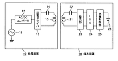
- FIG. 11 is a diagram illustrating a configuration example in which power is supplied from a conventional power supply device to a terminal device in a non-contact manner by an electromagnetic induction method.
- the power supply apparatus 10 that is a primary device converts an AC power supply 11 such as AC 100 V into a DC low-voltage power supply by an AC-DC converter 12.
- the direct-current low-voltage power obtained by the AC-DC converter 12 is supplied to the power transmission driver 13.
- the power transmission driver 13 is connected to a power transmission circuit in which a capacitor 14 and a primary side coil 15 are connected, and transmitted power of a predetermined frequency is supplied from the power transmission driver 13 to the primary side coil 15.
- the secondary side coil 21 and the capacitor 22 are connected to the rectifying unit 23, and the secondary side coil 21 receives the power from the primary side coil 15.
- the series circuit of the secondary coil 21 and the capacitor 22 is connected to the rectifying unit 23, and the rectifying unit 23 rectifies the power receiving power source to obtain a DC power source having a predetermined voltage Va.
- the predetermined voltage Va for example, DC power slightly exceeding 5V is obtained.
- the direct current power obtained by the rectifying unit 23 is supplied to the regulator 24 to make the voltage constant at a constant voltage (for example, 5V).
- the constant voltage DC power obtained by the regulator 24 is supplied to the charge control unit 25, and the secondary battery 26 is charged under the control of the charge control unit 25.
- the difference between the input voltage and the output voltage of the regulator 24 of the secondary device which is usually referred to as LDO (Low Drop Out)
- LDO Low Drop Out
- the series regulator that is applied to the case is used.
- the received power at the terminal device is relatively small power of about 1 W to 5 W.
- a terminal device to obtain a larger received power such as 10 W or 15 W by non-contact transmission using an electromagnetic induction method.
- the regulator 24 using the LDO has a problem that a large current flows and the loss of the coil is large.
- the receiving coil generates heat due to a change in received power
- three examples of received power of 5 W, 10 W, and 15 W are shown.
- the current value becomes 1A when the received power is 5W, 2A when the received power is 5W, and 3A when the received power is 5W.
- the resistance value of the secondary coil 21 is determined by the cross-sectional area of the secondary coil 21, it is constant at any power. In the example of FIG. 12, the resistance value of the secondary coil 21 is set to 0.4 ⁇ .
- the conversion formula between the secondary power loss and temperature is 20 ° C./0.6 W
- the heat generation temperature of the secondary coil 21 at each received power changes as shown in FIG. That is, when the received power is 5 W, the temperature is about 13 ° C., 10 W is about 53 ° C., and 15 W is about 120 ° C.
- the conversion formula between the secondary power loss and the temperature is set to 20 ° C./0.6 W because the temperature characteristics of the two types of terminal devices having the non-contact power supply coil are measured. based on. That is, as shown in FIG. 13, when the temperature characteristic T1 of one type of terminal device and the temperature characteristic T2 of another type of terminal device are measured, the temperature rises almost linearly with changes in power loss. was gotten. A conversion equation of 20 ° C./0.6 W was obtained from the characteristics obtained by linearly approximating these characteristics T1, T2.
- FIG. 14 is a diagram illustrating the relationship between the received power and the received frequency, where the characteristic W1 is a regulator using an LDO and the characteristic W2 is a switching regulator. As can be seen by comparing these characteristics W1 and W2, for example, in the case of the characteristic W1 using LDO, the received power is high in the vicinity of a specific frequency band. On the other hand, in the case of the characteristic W2 using the switching regulator, the received power is low in the frequency band where the received power is high in the characteristic W1.
- the purpose of the present disclosure is to solve problems such as heat generation and inefficiency when transmission power is increased in a non-contact power supply system.
- the contactless power supply system of the present disclosure is a contactless power supply system including a power supply device and a terminal device that receives power from the power supply device.
- the power feeding device is fed from a primary coil, a driver that supplies transmission power to the primary coil, a primary control unit that controls transmission power supplied by the driver in a plurality of stages, and a primary coil.
- a primary communication unit that communicates with the power receiving side.
- the terminal device includes: a secondary coil that receives power; a rectifier that rectifies the received power obtained by the secondary coil; a regulator that converts the received power rectified by the rectifier into power of a predetermined voltage; A side communication unit and a secondary side control unit that controls the regulator.
- the regulator performs received power conversion operation by a plurality of methods.
- the secondary side control unit controls the system of the transformation operation performed by the regulator based on the information received by the secondary side communication unit that communicates with the primary side communication unit.
- the terminal device of the present disclosure includes a secondary coil that receives power transmitted from the power supply device, a rectifier that rectifies the received power obtained by the secondary coil, and a predetermined amount of received power rectified by the rectifier.
- a regulator that converts the power into voltage power, a communication unit, and a control unit are provided. The regulator performs received power conversion operation by a plurality of methods.
- a control part controls the system of the transformation operation which a regulator performs based on the information acquired from the electric power feeder in the communication part.
- the contactless power supply device of the present disclosure is a communication that communicates with a primary coil, a driver that supplies transmission power to the primary coil, and a device that receives power supplied from the primary coil.
- Unit and a control unit A control part controls the transmission power which a driver supplies to a primary side coil in multiple steps, and determines transmission power based on the information which the communication part received.
- the non-contact power feeding method of the present disclosure is applied when non-contact power feeding is performed from a power feeding device including a primary side coil to a terminal device including a secondary side coil.
- a regulator that converts the power received by the secondary coil into power of a predetermined voltage is performed by a plurality of conversion operations. And based on the information obtained by communication with an electric power feeder and a terminal device, the system of the transformation operation which a regulator performs is set.
- the regulator included in the terminal device that receives the power transmitted from the power supply apparatus is set to a method for performing an appropriate transformation operation based on information instructed from the power supply apparatus.
- the conversion method at the regulator is set to an appropriate and efficient conversion method, so that the transmission efficiency can be increased and the coil heat is generated. Can be effectively prevented.
- FIG. 1 is a block diagram illustrating a system configuration example according to an embodiment of the present disclosure. It is a characteristic view by the example of change of received electric power by one embodiment of this indication. It is a block diagram which shows the structural example (example 1) of the regulator by one embodiment of this indication. It is a figure which shows the operation state of the regulator of the example of FIG. It is a block diagram which shows the structural example (example 2) of the regulator by one embodiment of this indication. It is a block diagram which shows the structural example (example 3) of the regulator by one embodiment of this indication.
- 5 is a flowchart illustrating an operation example (an example of communication from a primary side) according to an embodiment of the present disclosure.
- FIG. 5 is a flowchart illustrating an operation example (an example of communication from a secondary side) according to an embodiment of the present disclosure. It is a flowchart which shows the operation
- FIG. 1 is a diagram illustrating a configuration example of a contactless power feeding system according to an example of an embodiment of the present disclosure.
- the contactless power supply system of the present disclosure includes a power supply device 100 that is a primary device and a terminal device (power receiving device) 200 that is a secondary device, and supplies power in a contactless manner by an electromagnetic induction method.
- the power supply device 100 is a device that receives power from a commercial AC power source and supplies power to the terminal device 200 in a contactless manner.
- the terminal device 200 includes a load circuit that operates with the power supplied from the power supply device 100.
- the terminal device 200 may include a secondary battery that is charged by a power source supplied from the power supply device 100.
- the terminal device 200 can be applied to various terminal devices (electronic devices) such as a mobile phone terminal device and a portable audio playback device.
- the power supply apparatus 100 that is a primary device converts an AC power supply 101 such as AC 100 V into a DC low-voltage power supply by an AC-DC converter 102.
- the DC low-voltage power obtained by the AC-DC converter 102 is supplied to the power transmission driver 103.
- the use of the AC power supply 101 is one example.
- a DC power supply may be used as an input power supply.
- a power transmission circuit in which a capacitor 105 and a primary coil 106 are connected is connected to the power transmission driver 103, and transmitted power having a predetermined frequency is supplied from the power transmission driver 103 to the primary coil 106.
- the power supply apparatus 100 includes a control unit (primary side control unit) 104 that controls power supply processing, and the control unit 104 controls transmission power supplied from the power transmission driver 103 to the primary side coil 106.
- the power supply apparatus 100 of the example of the present embodiment is configured so that transmission power can be variably set in a plurality of stages, and the control unit 104 sets a transmission power value in any of the plurality of stages. A specific example of setting the transmission power will be described later.
- the power supply apparatus 100 includes a communication unit 107, and the communication unit 107 communicates with the terminal device 200 in both directions.
- the communication by the communication unit 107 is performed by superimposing a transmission signal on the transmitted power supplied from the power transmission driver 103 to the primary coil 106, for example.
- the information is modulated and transmitted by ASK (amplitude shift keying) or the like.
- ASK amplitude shift keying
- the transmission of information from the terminal device 200 side to the communication unit 107 is also performed in the same manner.
- transmission of information from the terminal device 200 side to the communication unit 107 may be transmission using a subcarrier different from the frequency of transmitted power.
- the terminal device 200 that is a secondary device will be described.
- the secondary coil 201 and the capacitor 202 are connected to the rectifying unit 203, and the secondary coil 201 receives the power from the primary coil 106.
- the primary side coil 106 and the secondary side coil 201 are usually arranged at close positions.
- the rectifying unit 203 rectifies a power source having a predetermined frequency received by the secondary coil 201 to obtain a DC power source.
- the regulator 210 is a voltage converter that converts the voltage of the input power source into a predetermined voltage, and a DC power source having a predetermined voltage obtained by the regulator 210 is supplied to the load circuit 204. Note that a secondary battery may be charged instead of the load circuit 204.
- the regulator 210 of the example of the present disclosure is configured to perform a received power conversion operation using a plurality of methods.
- the regulator 210 includes two types of conversion circuits, a DC-DC converter 211 and an LDO 212.
- the DC-DC converter 211 is called a switching regulator, and is a circuit that switches an input power source at a relatively high speed with a switching element, and rectifies and smoothes the switched power source to obtain a DC power source having a desired voltage.
- the DC-DC converter 211 has a wide variable range of input voltage.
- the LDO 212 is a series regulator that controls the amount of voltage drop in the transistor element to make a DC power supply with a desired voltage.
- the LDO 212 performs efficient voltage conversion when the variable range of the input voltage is narrow and the input voltage is slightly higher than the output voltage.
- the regulator 210 converts the voltage of the input power source into a stable constant voltage using one of the circuits of the DC-DC converter 211 and the LDO 212.
- the circuit used by the regulator 210 for the conversion operation is determined by an instruction from a control unit (secondary control unit) 205 that controls power reception.
- the DC-DC converter 211 is used when the input voltage is a relatively high voltage
- the LDO 212 is used when the input voltage is a relatively low voltage. Details of the selection operation of the DC-DC converter 211 and the LDO 212 under the control of the control unit 205 will be described later.
- the terminal device 200 includes a communication unit 206 and performs bidirectional communication with the communication unit 107 on the power supply apparatus 100 side.
- the series circuit of the secondary coil 201 and the capacitor 202 is connected to the communication unit 206 and detects a signal superimposed on the power supplied from the power supply apparatus 100.
- the signal transmitted from the communication unit 107 is received.
- a signal transmitted from the communication unit 206 is supplied to a series circuit of the secondary coil 201 and the capacitor 202.
- the terminal device 200 includes a temperature sensor 207 and measures the temperature in the vicinity of the secondary coil 201. Data on the temperature measured by the temperature sensor 207 is supplied to the control unit 205.
- the contactless power supply system includes at least three stages of supplying power at 5 W, supplying power at 10 W, and supplying power at 15 W when supplying power from the power supply apparatus 100 to the terminal device 200.
- the power supply can be set to When the terminal device 200 receives the supplied power, the input voltage Vx in the regulator 210 corresponding to the supplied power is set, and the received power of the input voltage Vx is converted into a constant voltage by the regulator 210. Output. Setting of the input voltage Vx in the regulator 210 is performed under the control of the control unit 205. At this time, the control unit 205 performs control so as to perform the conversion operation using either the DC-DC converter 211 or the LDO 212 as described above.
- FIG. 2 is a diagram illustrating an example of power supply power, a received voltage at the terminal device 200 (that is, an input voltage Vx at the regulator 210), loss power, and heat generation.
- the conditions for generating heat are the same as those in FIG. In FIG. 2, three examples of 5W power supply, 10W power supply, and 15W power supply are shown.
- the input voltage Vx (secondary side voltage) in the regulator 210 is set to 5 V, 10 V, and 15 V, respectively, and the terminal apparatus 200 In each case, the secondary current obtained in step 1 is set to about 1A.
- the resistance value of the secondary side coil 201 is the same in any example, and the secondary side power loss is 0.4 W in any power because the secondary side current is 1 A when any power is supplied. become. Therefore, the heat generation temperature of the secondary coil 201 is about 13 ° C. for any power. 2 is calculated under the conditions (20 ° C./0.6 W) set in the example of FIG.
- Example 1 Next, an example of a specific configuration of the regulator 210 will be described. Here, three examples of Example 1, Example 2, and Example 3 will be described.
- FIG. 3 is a diagram illustrating a configuration of the regulator 210 of the first example.
- a DC-DC converter 211 and an LDO 212 are connected in series.
- the LDO 212 is connected to the subsequent stage of the DC-DC converter 211, but the reverse connection order may be used. Only one of the DC-DC converter 211 and the LDO 212 operates. The stopped side of the DC-DC converter 211 and the LDO 212 outputs the input signal as it is.
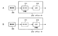
- FIG. 4 is a diagram showing an operation state of the regulator 210 in the example of FIG.
- the control unit 205 operates the DC-DC converter 211 to pass through the LDO 212. By doing so, the power source converted by the DC-DC converter 211 is obtained at the output section of the regulator 210.
- the control unit 205 operates the LDO 212 to pass the DC-DC converter 211. By doing so, the power source converted by the LDO 212 is obtained at the output section of the regulator 210.
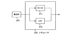
- FIG. 5 is a diagram illustrating a configuration of the regulator 210 of the second example.
- the DC-DC converter 211 and the LDO 212 are connected in parallel. Then, the control unit 205 is controlled so that only one of the DC-DC converter 211 and the LDO 212 operates.
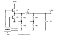
- FIG. 6 is a diagram illustrating a configuration of the regulator 210 of the third example.
- the configuration shown in FIG. 6 is a circuit in which a DC-DC converter 211 and an LDO 212 share a circuit.
- two transistors Q1 and Q2 are connected between the input terminal 210a of the regulator 210 and the ground potential portion.
- the two transistors Q1 and Q2 are turned on / off by the control unit 205.
- a connection point between the transistors Q1 and Q2 is connected to the output terminal 210b of the regulator 210 via the coil L1.
- One end of a smoothing capacitor C1 is connected to a connection point between the coil L1 and the output terminal 210b.
- a series circuit of voltage detection resistors R1 and R2 is connected between a connection point between the transistors Q1 and Q2 and the coil L1 and the ground potential portion.
- a series circuit of voltage detection resistors R3 and R4 is connected between the connection point of the coil L1 and the output terminal 210b and the ground potential portion.
- the control unit 205 detects the voltage at the connection point between the resistors R1 and R2 and the voltage at the connection point between the resistors R3 and R4.
- the control unit 205 performs switching operation by turning on and off the two transistors Q1 and Q2 at high speed. At this time, the control unit 205 monitors the voltage charged in the smoothing capacitor C1 from the voltage at the connection point of the resistors R3 and R4, and the two transistors Q1 so that the detected voltage becomes appropriate. , Q2 are controlled.
- the transistor Q1 is controlled to be a voltage control element.
- the control unit 205 sets the transistor Q2 to an open state. At this time, the control unit 205 detects the voltage at the connection point of the resistors R1 and R2, and controls the voltage drop amount in the transistor Q1 so that the voltage becomes appropriate.
- Example 1 Next, an example of power supply processing performed between the power supply apparatus 100 and the terminal apparatus 200 will be described.
- Example 1 FIG. 7 in which processing is performed by communication from the power supply apparatus 100
- Example 2 FIG. 8 in which processing is performed by communication from the terminal apparatus 200
- the primary side coil 106 of the power supply apparatus 100 and the secondary side coil 201 of the terminal apparatus 200 are close to a state in which power transmission is possible.
- FIG. 7 is a flowchart illustrating an example of the power supply process of Example 1. The processing will be described with reference to FIG. 7.
- the control unit 104 of the power supply apparatus 100 that is the primary side device starts supplying the transmission power from the power transmission driver 103 to the primary side coil 106 (step S ⁇ b> 11).
- a relatively low power for starting is set. That is, the control part 104 sets electric power lower than electric power like 5W and 15W mentioned above.
- the low power for startup may be power that enables communication between the primary communication unit 107 and the secondary communication unit 206.
- control part 104 may set 5W which is the smallest electric power among the electric power which can be set up in a plurality of steps mentioned above as transmission power for starting.
- the communication unit 206 and the control unit 205 of the terminal device 200 that is the secondary device are activated (step S12).
- a signal indicating activation may be transmitted from the communication unit 206 of the terminal device 200 to the communication unit 107 of the power supply apparatus 100.
- the control unit 104 of the power supply apparatus 100 transmits a signal for confirming the load power required by the load circuit 204 of the terminal apparatus 200 from the communication unit 107 (step S13).
- the control unit 205 returns information indicating the load power from the communication unit 206, and the control unit 104 of the power supply device 100 transmits the information. Check the load power.
- control unit 104 determines transmission power corresponding to the confirmed load power (step S14). For example, the control unit 104 selects transmission power that is the same as or greater than the load power. At this time, the control unit 104 may transmit the determined transmission power information from the communication unit 107 to the terminal device 200.
- the control unit 205 of the terminal device 200 determines from the information received by the communication unit 206 whether the transmission power is greater than or equal to the threshold THx or less than the threshold THx.
- the control unit 205 instructs to use the DC-DC converter 211 as the regulator 210 (step S15).
- the control unit 205 instructs to use the LDO 212 as the regulator 210 (step S16).
- the input voltage of regulator 210 is set appropriately based on, for example, transmission power.
- the control unit 205 sets one of the input voltages 5V, 10V, and 15V corresponding to the transmission powers 5W, 10W, and 15W, as shown in FIG.
- control part 104 of the electric power feeder 100 starts the electric power feeding by the transmission power determined by step S14 (step S17).
- the regulator 210 in the terminal apparatus 200 uses the appropriate one of the DC-DC converter 211 and the LDO 212. Performs voltage conversion.
- FIG. 8 is a flowchart illustrating an example of the power supply process of Example 2.
- the control unit 104 of the power supply apparatus 100 that is the primary device starts supplying the transmission power from the power transmission driver 103 to the primary coil 106 (step S ⁇ b> 21).
- step S ⁇ b> 21 the control unit 104 of the power supply apparatus 100 that is the primary device starts supplying the transmission power from the power transmission driver 103 to the primary coil 106.
- step S11 of the flowchart of FIG. 7 similarly to the processing in step S11 of the flowchart of FIG. 7, a relatively low power for starting is set.
- step S22 the communication unit 206 and the control unit 205 of the terminal device 200 that is the secondary device are activated.
- the control unit 205 of the terminal device 200 transmits a signal for confirming the transmission power of the power supply device 100 from the communication unit 206 (step S23).
- the control unit 104 returns information indicating the transmission power from the communication unit 107, and the control unit 205 of the terminal apparatus 200 transmits the information. Check the transmission power.
- the control unit 205 determines load power corresponding to the confirmed transmission power (step S24). That is, the load power consumed by the load circuit 204 is determined within a range not exceeding the presented transmission power. Then, the control unit 205 determines whether the determined load power is greater than or equal to the threshold value THx or less than the threshold value THx. Here, when the load power is equal to or higher than the threshold value THx, the control unit 205 instructs to use the DC-DC converter 211 as the regulator 210 (step S25). If the load power is less than the threshold value THx, the control unit 205 instructs the regulator 210 to use the LDO 212 (step S26).
- the input voltage of the regulator 210 is set appropriately based on, for example, transmission power.
- the control unit 205 sets one of the input voltages 5V, 10V, and 15V corresponding to the transmission powers 5W, 10W, and 15W, as shown in FIG.
- step S27 the control part 104 of the electric power feeder 100 starts the electric power feeding by the transmission power notified by step S23 (step S27).
- the regulator 210 performs voltage conversion using the appropriate one of the DC-DC converter 211 and the LDO 212 in accordance with the load power set in the terminal device 200. To do.
- FIG. 9 is a flowchart illustrating a first modification of the power supply process. 7 and 8, the regulator 210 is set at the start of power supply. On the other hand, in the first modification, the control unit 205 of the terminal device 200 is an example in which the regulator 210 is set based on the temperature detected by the temperature sensor 207.
- the control unit 205 of the terminal device 200 instructs the regulator 210 to use the LDO 212 on the assumption that the received power is less than the threshold value THx (step S31). Then, after the power feeding device 100 starts power transmission (step S32), the control unit 205 of the terminal device 200 receives power for a predetermined X seconds (step S33), and determines whether power feeding is completed. This is performed (step S34).
- the X seconds here are, for example, about 60 seconds.
- step S34 When it is determined in step S34 that the power supply is completed, the control unit 205 performs a process of completing the power reception (step S35). When it is determined in step S34 that power feeding continues, the control unit 205 determines whether or not the temperature detected by the temperature sensor 207 is equal to or higher than a predetermined threshold temperature ⁇ ° C. (step S36). If it is determined that the temperature is not higher than ⁇ ° C., the control unit 205 returns to the process of step S33.
- step S36 When it is determined in step S36 that the temperature is equal to or higher than ⁇ ° C., the control unit 205 instructs the regulator 210 to use the DC-DC converter 211 and changes the input voltage of the regulator 210 to a high voltage such as 10V. (Step S37). After changing the setting of the regulator 210, the control unit 205 determines whether or not the supplied power can be normally received (step S38). If the power is not normally received by the determination, the control unit 205 is in an abnormal state. Then, the power supply process is stopped (step S39).
- step S38 If it is determined in step S38 that power can be normally received, the control unit 205 receives power for a predetermined X seconds (step S40), and determines whether or not power supply is completed (step S41).
- step S41 When it is determined in step S41 that the power supply is completed, the control unit 205 performs a process of completing the power reception (step S42). When it is determined in step S41 that power supply continues, the control unit 205 determines whether or not the temperature detected by the temperature sensor 207 is equal to or higher than a predetermined threshold temperature ⁇ ° C. (step S43). If it is determined that the temperature is not higher than ⁇ ° C., the control unit 205 returns to the process of step S40. When it is determined in step S40 that the temperature is equal to or higher than ⁇ ° C., the control unit 205 stops the power supply process because it is in an abnormal state (step S44).
- the control unit 205 determines the conversion method in the regulator 210 by determining whether or not the temperature in the vicinity of the secondary coil 201 is equal to or higher than a predetermined threshold temperature ⁇ ° C. By doing so, an appropriate conversion method and input power can be set. That is, in a state where the secondary coil 201 hardly generates heat, the control unit 205 determines that proper non-contact power feeding is performed and performs power reception under the initially set conditions. In a state where the secondary coil 201 generates heat to some extent, it is determined that the power supply power is large, and the control unit 205 can appropriately receive power by changing the conversion method and the input voltage.
- processing shown in the flowchart of FIG. 9 may be performed independently. For example, after the power supply start processing shown in the flowchart of FIG. 7 or FIG. However, the processing shown in the flowchart of FIG. 9 may be performed.
- FIG. 10 is a flowchart illustrating a second modification of the power supply process.
- the second modification is an example in which the control unit 205 of the terminal device 200 determines the power receiving efficiency of the supplied power and sets the regulator 210.
- the control unit 205 of the terminal device 200 instructs the regulator 210 to select one of the DC-DC converter 211 and the LDO 212 and perform a conversion operation (step S51). And after the electric power feeder 100 starts power transmission (step S52), the control part 205 of the terminal device 200 receives electric power for X seconds decided beforehand (step S53), and the electric power reception efficiency of the present electric power feeding is beforehand It is determined whether or not the determined ⁇ % or more (step S54).
- the power reception efficiency is calculated by the control unit 205.
- the control unit 205 acquires information on transmitted power from the power supply apparatus 100, and further measures the power received by the terminal device 200, and the control unit 205 uses the received power and the supplied power. Power reception efficiency is obtained by calculation.
- step S54 When it is determined in step S54 that the power reception efficiency is not ⁇ % or more, the control unit 205 instructs to switch the conversion method of the regulator 210 to another method (step S55). At this time, when the input voltage needs to be set, the input voltage is also switched. Thereafter, it is determined whether or not the power supply is completed (step S56). When it is determined in step S56 that the power supply has been completed, the control unit 205 performs a process of completing the power reception (step S57). When it is determined in step S56 that power feeding continues, the control unit 205 receives power for a predetermined X seconds (step S58), and the power receiving efficiency of the current power feeding power is determined to be a predetermined ⁇ %. It is determined whether or not this is the case (step S59).
- step S60 when it is determined that the power reception efficiency is equal to or higher than ⁇ %, the control unit 205 returns to the process of step S58. If it is determined in step S59 that the power reception efficiency is not equal to or higher than ⁇ %, the control unit 205 determines that power cannot be received in an appropriate state regardless of the setting of the regulator 210, and terminates the power supply. Is performed (step S60).
- control unit 205 switches the conversion method in the regulator 210 based on the actual power receiving efficiency, so that an appropriate conversion method and input power can be set.
- processing shown in the flowchart of FIG. 10 may be performed independently. However, for example, after the power supply start processing shown in the flowchart of FIG. 7 or FIG. The processing shown in the flowchart of FIG. 10 may be performed. Alternatively, the control unit 205 may use the selection process based on the temperature shown in the flowchart of FIG. 9 and the selection process based on the efficiency shown in the flowchart of FIG.
- the DC-DC converter 211 and the LDO 212 are provided as the regulator 210.
- two types of regulators having different conversion methods may be provided, and the two types of regulators may be switched based on transmission power or load power.
- the example in which the feed power is changed in three stages as shown in FIG. On the other hand, the feed power may be changed in two steps or four or more steps.
- the relationship between the feed power and the voltage or current shown in FIG. 2 is an example, and other feed power, voltage, or current may be set.
- transmission power information is transmitted from the power supply apparatus 100 to the terminal apparatus 200.
- the communication unit 107 of the power supply apparatus 100 and the communication unit 206 of the terminal apparatus 200 perform communication by superimposing a transmission signal on the power supply power.
- communication may be performed using a wireless transmission line or a wired transmission line different from the system that supplies power.
- a power feeding device and a power receiving device that receives power from the power feeding device;
- the power supply device A primary coil;
- a primary-side control unit that controls transmission power supplied by the driver in a plurality of stages;
- a primary side communication unit that communicates with a side that receives power supplied from the primary side coil;
- the power receiving device is: A secondary coil that receives power sent from the primary coil; A rectifier that rectifies received power obtained in the secondary coil; A regulator that converts the received power rectified by the rectification unit into power of a predetermined voltage, and performs the conversion operation by a plurality of methods,
- a secondary communication unit that communicates with the primary communication unit;
- a non-contact power feeding system comprising: a secondary side control unit that controls a method of a transformation operation performed by the regulator based on information received by the secondary side communication unit from the primary side communication unit.
- the secondary side control unit When the information on the transmission power determined by the primary side control unit is transmitted from the primary side communication unit to the secondary side communication unit, the secondary side control unit performs a conversion operation method performed by the regulator. Is determined to be a method suitable for the transmitted transmission power.
- (3) Communication between the primary side communication unit and the secondary side communication unit is communication that superimposes a transmission signal on power transmitted from the primary side coil to the secondary side coil, After transmitting power transmission information from the primary side communication unit to the secondary side communication unit while performing power transmission from the primary side coil to the secondary side coil with small power for startup,
- the primary side control unit determines transmission power based on information transmitted from the secondary side communication unit to the primary side communication unit. Any one of (1) to (3) Contactless power supply system.
- Communication between the primary side communication unit and the secondary side communication unit is communication that superimposes a transmission signal on power transmitted from the primary side coil to the secondary side coil, After transmitting power information from the secondary side communication unit to the primary side communication unit while performing power transmission from the primary side coil to the secondary side coil with small power for startup, The non-contact power feeding system according to (1) or (2), wherein the secondary side control unit sets transmission power indicated by the load power information.
- the secondary side control unit determines load power based on information transmitted from the secondary side communication unit to the primary side communication unit.
- the non-contact power feeding system includes a temperature sensor that detects a temperature in the vicinity of the secondary coil, The non-contact power feeding system according to any one of (1) to (6), wherein the secondary side control unit controls a method of a transformation operation performed by the regulator based on a temperature detected by the temperature sensor. . (8) The non-contact power feeding system according to any one of (1) to (7), wherein the secondary side control unit controls a method of a transformation operation performed by the regulator based on an efficiency of receiving transmitted power. (9) The non-contact power feeding system according to any one of (1) to (8), wherein the regulator includes two regulators, a series regulator and a switching regulator.
- a secondary coil that receives power sent from the primary coil of the power supply device; A rectifier that rectifies received power obtained in the secondary coil; A regulator that converts the received power rectified by the rectification unit into power of a predetermined voltage, and performs the conversion operation by a plurality of methods,
- a communication unit that communicates with the power supply device;
- a terminal device comprising: a control unit that controls a method of a transformation operation performed by the regulator based on information received by the communication unit.
- the control unit determines a conversion operation method performed by the regulator to a method suitable for the transmitted transmission power.
- Communication in the communication unit is communication that superimposes a transmission signal on power transmitted from the primary coil to the secondary coil,
- the terminal device includes two regulators, a series regulator and a switching regulator.
- Communication by the communication unit is communication that superimposes a transmission signal on power transmitted from the primary coil, While transmitting power transmission from the primary side coil with small power for startup, the control unit transmits the transmission power indicated by the transmission power information after transmitting the transmission power information from the communication unit.
- a regulator that converts the power received by the secondary coil into power of a predetermined voltage is performed by a plurality of conversion operations
- a non-contact power feeding method that sets a method of a transformation operation performed by the regulator based on information obtained through communication between the power feeding device and the power receiving device.
- SYMBOLS 10 Power feeding apparatus, 11 ... AC power supply, 12 ... AC / DC converter, 13 ... Power transmission driver, 14 ... Capacitor, 15 ... Primary coil, 20 ... Terminal device, 21 ... Secondary coil, 22 DESCRIPTION OF SYMBOLS ... Capacitor, 23 ... Rectification part, 24 ... Regulator, 25 ... Charge control part, 26 ... Secondary battery, 100 ... Power supply apparatus, 101 ... AC power supply, 102 ... AC / DC converter, 103 ... Power transmission driver, 104 ... Primary Side control unit, 105 ... capacitor, 106 ... primary coil, 107 ... primary side communication unit, 200 ... terminal device, 201 ...
- secondary side coil 202 ... capacitor, 20 3 ... rectifying unit, 204 ... load circuit, 205 ... secondary side control unit, 206 ... secondary side communication unit, 207 ... Temperature sensor, 210 ... Regulator, 211 ... DC-DC converter, 212 ... LDO
Abstract
1次側コイルを備えた給電装置から2次側コイルを備えた端末装置に非接触給電を行う場合に、2次側コイルが受電した電力を所定電圧の電力に変換するレギュレータを、複数の方式の変換動作で行うようにする。そして、給電装置と端末装置との通信で得た情報に基づいて、レギュレータが行う変圧動作の方式を設定するようにした。
Description
本開示は、非接触給電システム、端末装置、非接触給電装置および非接触給電方法に関する。
充電装置などの機器が、端末装置に対して、端子などを直接接続させない非接触状態で、電源を供給することが従来から行われている。
従来から行われている非接触電源伝送方式としては、電磁誘導方式が知られている。これは、電力を送信する側の機器に送電用コイルを配置し、受信側の端末装置側に受電用コイルを配置するものである。この電磁誘導方式では、送信側の機器の送電用コイルを配置した箇所と、受信側の機器の受電用コイルを配置した箇所とを近接させて、両コイル間を磁束結合して、非接触で電力を送る処理が行われる。
従来から行われている非接触電源伝送方式としては、電磁誘導方式が知られている。これは、電力を送信する側の機器に送電用コイルを配置し、受信側の端末装置側に受電用コイルを配置するものである。この電磁誘導方式では、送信側の機器の送電用コイルを配置した箇所と、受信側の機器の受電用コイルを配置した箇所とを近接させて、両コイル間を磁束結合して、非接触で電力を送る処理が行われる。
また、ある程度離れた距離の端末装置に対して非接触で効率よく電力を供給する方式として、磁界共鳴方式と称されるものが開発されている。これは、送電側装置と受電側装置のそれぞれに、コイルとコンデンサなどからなるLC回路を設けて、双方の回路間で電場・磁場を共鳴させることで、ワイヤレスで電力を伝送するものである。
電磁誘導方式と磁界共鳴方式のいずれの場合でも、送電側装置が送電用コイルを備え、受電側装置が受電用コイルを備える。以下の本明細書で電磁誘導方式と述べた場合、磁界共鳴方式などの類似した他の非接触電源伝送方式も含む。
図11は、従来の給電装置から端末装置に非接触で電磁誘導方式により給電を行う構成例を示す図である。
1次側機器である給電装置10は、AC100Vなどの交流電源11をAC-DCコンバータ12で直流低圧電源に変換する。AC-DCコンバータ12で得られた直流低圧電源が、送電ドライバ13に供給される。送電ドライバ13には、コンデンサ14と1次側コイル15とが接続された送電回路が接続してあり、送電ドライバ13から所定の周波数の送電電力が1次側コイル15に供給される。
1次側機器である給電装置10は、AC100Vなどの交流電源11をAC-DCコンバータ12で直流低圧電源に変換する。AC-DCコンバータ12で得られた直流低圧電源が、送電ドライバ13に供給される。送電ドライバ13には、コンデンサ14と1次側コイル15とが接続された送電回路が接続してあり、送電ドライバ13から所定の周波数の送電電力が1次側コイル15に供給される。
2次側機器である端末装置20は、2次側コイル21とコンデンサ22とが整流部23に接続してあり、1次側コイル15からの電力を2次側コイル21が受電する。
2次側コイル21とコンデンサ22との直列回路は、整流部23に接続してあり、整流部23が受電電源を整流して、所定電圧Vaの直流電源を得る。所定電圧Vaとしては、例えば5Vを若干越える程度の直流電力を得る。
2次側コイル21とコンデンサ22との直列回路は、整流部23に接続してあり、整流部23が受電電源を整流して、所定電圧Vaの直流電源を得る。所定電圧Vaとしては、例えば5Vを若干越える程度の直流電力を得る。
整流部23で得られた直流電源が、レギュレータ24に供給され、一定の電圧(例えば5V)に定電圧化する。このレギュレータ24で得られた定電圧の直流電源が充電制御部25に供給され、充電制御部25の制御で2次電池26の充電が行われる。
このような非接触給電システムを構成した場合、2次側機器のレギュレータ24は、通常、LDO(Low Drop Out:低ドロップアウト)と称される、入力電圧と出力電圧との差が比較的小さい場合に適用されるシリーズレギュレータが使用される。レギュレータ24としてLDOを使用することで、受電電力が5W程度の低電力用として、ある程度効率の高いシステムを組むことができる。
ところで、非接触で電力伝送を行う場合において、伝送電力の大電力化に対する要望がある。すなわち、現在実用化されている非接触給電システムでは、端末装置での受電電力が1W~5W程度の比較的小さな電力である。これに対して、電磁誘導方式による非接触伝送で、端末装置が10Wや15Wのような、より大きな受電電力を得るようにする要望がある。
ここで、図11に示す構成で大電力の受電を行うようにした場合、LDOを使用したレギュレータ24では、大電流が流れるためコイルの損失が大きいという問題がある。
比較的大きな電力や高い電圧を扱うレギュレータとしては、いわゆるDC-DCコンバータと称されるスイッチングレギュレータが知られている。
特許文献1には、電源装置において、LDOを使用したレギュレータと、スイッチングレギュレータとを併用する点についての記載がある。この特許文献1には、重負荷時にはスイッチングレギュレータを使用して、軽負荷時にはLDOによるレギュレータを使用する点についての記載がある。
特許文献1には、電源装置において、LDOを使用したレギュレータと、スイッチングレギュレータとを併用する点についての記載がある。この特許文献1には、重負荷時にはスイッチングレギュレータを使用して、軽負荷時にはLDOによるレギュレータを使用する点についての記載がある。
従来、特許文献1などに記載のように、ACアダプタなどの電源装置においては、LDOを使用したレギュレータとスイッチングレギュレータとを併用する場合に、入力電源の電圧を検出して2つのレギュレータを切り替えるようにしている。
ここで、図11に示すような非接触給電システムの2次側機器のレギュレータには、同様の構成を適用することはできない。すなわち、図11に示す非接触給電システムを構成した場合、端末装置20内のレギュレータ24の入力電圧Vaはほぼ一定であり、受電電力が増えたときには、電流が増えるだけである。したがって、入力電圧の検出によってレギュレータを切り替える構成は適用できない。
ここで、図11に示すような非接触給電システムの2次側機器のレギュレータには、同様の構成を適用することはできない。すなわち、図11に示す非接触給電システムを構成した場合、端末装置20内のレギュレータ24の入力電圧Vaはほぼ一定であり、受電電力が増えたときには、電流が増えるだけである。したがって、入力電圧の検出によってレギュレータを切り替える構成は適用できない。
ここで、受電電力の変化によって、受電用コイルが発熱する例を、図12の表を参照して説明する。
図12の例では、受電電力が5W,10W,15Wの3つの例を示す。いずれの例でも整流部23が5Vに整流するとき、電流値は、受電電力5Wのとき1A、受電電力5Wのとき2A、受電電力5Wのとき3Aになる。2次側コイル21の抵抗値は、2次側コイル21の断面積で決まるため、どの電力でも一定である。図12の例では、2次側コイル21の抵抗値を0.4Ωとした。2次側コイル21の電力損失は、Q=I2Rの式より、電流の2乗と抵抗値の積で決まり、電流が増えるほど損失電力が増える。ここで、2次側電力損失と温度との変換式を20℃/0.6Wとしたとき、各受電電力での2次側コイル21の発熱温度は、図12に示すように変化する。すなわち、受電電力が5Wのとき約13℃になり、10Wのとき約53℃になり、15Wのとき約120℃になる。
図12の例では、受電電力が5W,10W,15Wの3つの例を示す。いずれの例でも整流部23が5Vに整流するとき、電流値は、受電電力5Wのとき1A、受電電力5Wのとき2A、受電電力5Wのとき3Aになる。2次側コイル21の抵抗値は、2次側コイル21の断面積で決まるため、どの電力でも一定である。図12の例では、2次側コイル21の抵抗値を0.4Ωとした。2次側コイル21の電力損失は、Q=I2Rの式より、電流の2乗と抵抗値の積で決まり、電流が増えるほど損失電力が増える。ここで、2次側電力損失と温度との変換式を20℃/0.6Wとしたとき、各受電電力での2次側コイル21の発熱温度は、図12に示すように変化する。すなわち、受電電力が5Wのとき約13℃になり、10Wのとき約53℃になり、15Wのとき約120℃になる。
なお、図12において、2次側電力損失と温度との変換式を20℃/0.6Wとしたのは、非接触給電用のコイルを備えた2種類の端末装置の温度特性を実測した結果に基づく。すなわち、図13に示すように、ある型式の端末装置の温度特性T1と、別の型式の端末装置の温度特性T2を測定したとき、それぞれ損失電力の変化にほぼ直線的に温度が上昇する特性が得られた。これら特性T1,T2を直線近似した特性から、20℃/0.6Wの変換式を得た。
ところで、発熱とは別の問題として、2次側の機器がスイッチングレギュレータを使用した場合、小電力での給電を受ける際の効率に問題がある。すなわち、図14は、受電電力と受電周波数との関係を示す図であり、特性W1はLDOを使用したレギュレータの場合で、特性W2はスイッチングレギュレータの場合である。この特性W1,W2を比較すると判るように、例えばLDOを使用した特性W1の場合には、特定の周波数帯域の近傍で受電電力が高くなる。一方、スイッチングレギュレータを使用した特性W2の場合には、特性W1で受電電力が高い周波数帯域では、受電電力が低くなってしまう。
このように、2次側の機器が備えるレギュレータの方式によって、適切な搬送周波数が変化し、レギュレータの方式の選定が簡単にはできないという問題がある。
本開示の目的は、非接触給電システムを組む場合において、送電電力を大電力化した場合の発熱や効率の悪さなどの問題を解決することにある。
本開示の非接触給電システムは、給電装置と、前記給電装置から給電を受ける端末装置とを備える非接触給電システムである。
給電装置は、1次側コイルと、1次側コイルに送電電力を供給するドライバと、ドライバが供給する送電電力を複数段階に制御する1次側制御部と、1次側コイルから給電される電力を受電する側と通信を行う1次側通信部とを備える。
端末装置は、電力を受電する2次側コイルと、2次側コイルに得られる受電電力を整流する整流部と、整流部が整流した受電電力を所定電圧の電力に変換するレギュレータと、2次側通信部と、レギュレータを制御する2次側制御部とを備える。
レギュレータは、受電電力の変換動作を複数の方式で行う。2次側制御部は、1次側通信部と通信を行う2次側通信部で受信した情報に基づいて、レギュレータが行う変圧動作の方式を制御する。
また、本開示の端末装置は、給電装置から送出される電力を受電する2次側コイルと、2次側コイルに得られる受電電力を整流する整流部と、整流部が整流した受電電力を所定電圧の電力に変換するレギュレータと、通信部と、制御部とを備える。
レギュレータは、受電電力の変換動作を複数の方式で行う。制御部は、通信部で給電装置から得た情報に基づいて、レギュレータが行う変圧動作の方式を制御する。
レギュレータは、受電電力の変換動作を複数の方式で行う。制御部は、通信部で給電装置から得た情報に基づいて、レギュレータが行う変圧動作の方式を制御する。
また、本開示の非接触給電装置は、1次側コイルと、1次側コイルに送電電力を供給するドライバと、1次側コイルから給電される電力を受電する側の装置と通信を行う通信部と、制御部とを備える。
制御部は、ドライバが1次側コイルに供給する送電電力を複数段階に制御し、通信部が受信した情報に基づいて送信電力を決定する。
制御部は、ドライバが1次側コイルに供給する送電電力を複数段階に制御し、通信部が受信した情報に基づいて送信電力を決定する。
また、本開示の非接触給電方法は、1次側コイルを備えた給電装置から2次側コイルを備えた端末装置に非接触給電を行う場合に適用される。
端末装置では、2次側コイルが受電した電力を所定電圧の電力に変換するレギュレータを、複数の方式の変換動作で行うようにする。そして、給電装置と端末装置との通信で得た情報に基づいて、レギュレータが行う変圧動作の方式を設定する。
端末装置では、2次側コイルが受電した電力を所定電圧の電力に変換するレギュレータを、複数の方式の変換動作で行うようにする。そして、給電装置と端末装置との通信で得た情報に基づいて、レギュレータが行う変圧動作の方式を設定する。
本開示によると、給電装置から送電される電力を受電する端末装置が備えるレギュレータが、給電装置から指示された情報に基づいて、適切な変圧動作を行う方式に設定される。
本開示によると、端末装置での受電電力がいずれの受電電力であっても、レギュレータでの変換方式が効率のよい適切な変換方式に設定され、伝送効率を高くすることができると共にコイルの発熱を効果的に防止できるようになる。
本開示の実施の形態に係る非接触給電システム、端末装置、非接触給電装置および非接触給電方法の例を、図面を参照しながら、以下の順で説明する。
1.給電装置と端末装置の構成例(図1~図2)
2.レギュレータの例(例1:図3~図4)
3.レギュレータの例(例2:図5)
4.レギュレータの例(例3:図6)
5.給電処理例(例1:図7)
6.給電処理例(例2:図8)
7.給電処理の変形例(変形例1:図9)
8.給電処理の変形例(変形例2:図10)
9.その他の変形例
1.給電装置と端末装置の構成例(図1~図2)
2.レギュレータの例(例1:図3~図4)
3.レギュレータの例(例2:図5)
4.レギュレータの例(例3:図6)
5.給電処理例(例1:図7)
6.給電処理例(例2:図8)
7.給電処理の変形例(変形例1:図9)
8.給電処理の変形例(変形例2:図10)
9.その他の変形例
[1.給電装置と端末装置の構成例]
図1は、本開示の一実施の形態の例に係る非接触給電システムの構成例を示す図である。
本開示の非接触給電システムは、1次側機器である給電装置100と、2次側機器である端末装置(受電装置)200で構成され、電磁誘導方式により非接触で電力を給電する。給電装置100は、商用交流電源などの供給を受けて、端末装置200に電源を非接触で給電する装置である。端末装置200は、給電装置100から供給される電源で作動する負荷回路を備える。あるいは端末装置200は、給電装置100から供給される電源で充電される2次電池を備えるようにしてもよい。端末装置200は、例えば携帯電話端末装置やポータブルオーディオ再生装置など、各種端末装置(電子機器)に適用可能である。
1次側機器である給電装置100は、AC100Vなどの交流電源101をAC-DCコンバータ102で直流低圧電源に変換する。AC-DCコンバータ102で得られた直流低圧電源が、送電ドライバ103に供給される。交流電源101を使用するのは1つの例であり、例えば直流電源を入力電源として使用してもよい。
送電ドライバ103には、コンデンサ105と1次側コイル106とが接続された送電回路が接続してあり、送電ドライバ103から所定の周波数の送電電力が1次側コイル106に供給される。
送電ドライバ103には、コンデンサ105と1次側コイル106とが接続された送電回路が接続してあり、送電ドライバ103から所定の周波数の送電電力が1次側コイル106に供給される。
給電装置100は、給電処理を制御する制御部(1次側制御部)104を備え、制御部104が、送電ドライバ103から1次側コイル106に供給される送電電力を制御する。本実施の形態の例の給電装置100は、送電電力を複数段階に可変設定できるようにしてあり、制御部104が、その複数段階のいずれかの送電電力値を設定する。送電電力を設定する具体例については後述する。
また給電装置100は、通信部107を備え、通信部107が端末装置200と双方向に通信を行う。この通信部107による通信は、例えば、送電ドライバ103から1次側コイル106に供給される送電電力に、伝送信号を重畳して行う。具体的には、1次側コイル106に供給される送電電力の周波数を搬送波として利用して、ASK(amplitude shift keying)などで情報を変調して伝送する。端末装置200側から通信部107への情報の伝送についても、同様の方法で行われる。あるいは、端末装置200側から通信部107への情報の伝送については、送電電力の周波数とは別の副搬送波を利用した伝送でもよい。近接したコイル間で、非接触により電力と共に情報を双方向で伝送する方式については、既に非接触ICカードとリーダとの間での通信などで各種方式のものが実用化されており、本開示の例ではいずれの方式を適用してもよい。
次に、2次側機器である端末装置200について説明する。
端末装置200は、2次側コイル201とコンデンサ202とが整流部203に接続してあり、1次側コイル106からの電力を2次側コイル201が受電する。電磁誘導方式の場合、通常は1次側コイル106と2次側コイル201は近接した位置に配置される。
整流部203は、2次側コイル201が受電した所定周波数の電源を整流して直流電源を得る。
端末装置200は、2次側コイル201とコンデンサ202とが整流部203に接続してあり、1次側コイル106からの電力を2次側コイル201が受電する。電磁誘導方式の場合、通常は1次側コイル106と2次側コイル201は近接した位置に配置される。
整流部203は、2次側コイル201が受電した所定周波数の電源を整流して直流電源を得る。
そして、整流部203で得られた直流電源が、レギュレータ210に供給される。レギュレータ210は、入力電源の電圧を、所定電圧に変換する電圧変換器であり、レギュレータ210で得られた所定電圧の直流電源が、負荷回路204に供給される。なお、負荷回路204の代わりに2次電池を充電するようにしてもよい。
本開示の例のレギュレータ210は、受電電力の変換動作を複数の方式で行う構成である。図1の例では、レギュレータ210は、DC-DCコンバータ211とLDO212の2つの方式の変換回路を備える。
DC-DCコンバータ211は、スイッチングレギュレータと称され、入力電源をスイッチング素子で比較的高速にスイッチングし、そのスイッチングされた電源を整流および平滑化して、所望の電圧の直流電源とする回路である。DC-DCコンバータ211は、入力電圧の可変範囲が広い。
DC-DCコンバータ211は、スイッチングレギュレータと称され、入力電源をスイッチング素子で比較的高速にスイッチングし、そのスイッチングされた電源を整流および平滑化して、所望の電圧の直流電源とする回路である。DC-DCコンバータ211は、入力電圧の可変範囲が広い。
LDO212は、トランジスタ素子での電圧降下量を制御して、所望の電圧の直流電源とするシリーズレギュレータである。LDO212は、入力電圧の可変範囲が狭く、出力電圧より若干高い程度の入力電圧であるとき、効率のよい電圧変換が行われる。
レギュレータ210は、DC-DCコンバータ211とLDO212のいずれか一方の回路を使用して入力電源の電圧を、安定した一定電圧に変換する。このレギュレータ210が変換動作に使用する回路は、受電を制御する制御部(2次側制御部)205からの指示で決まる。本開示の例の場合には、入力電圧が比較的高い電圧であるとき、DC-DCコンバータ211を使用し、入力電圧が比較的低い電圧であるとき、LDO212を使用する。この制御部205の制御によるDC-DCコンバータ211とLDO212の選択動作の詳細については後述する。
また端末装置200は、通信部206を備え、給電装置100側の通信部107と双方向に通信を行う。この通信部206が通信を行うために、2次側コイル201とコンデンサ202との直列回路が、通信部206に接続してあり、給電装置100から供給される電源に重畳された信号を検出して、通信部107から伝送された信号の受信を行う。また、通信部206から送信する信号が、2次側コイル201とコンデンサ202との直列回路に供給される。
また端末装置200は、温度センサ207を備え、2次側コイル201の近傍の温度を計測する。温度センサ207が計測した温度のデータが、制御部205に供給される。
また端末装置200は、温度センサ207を備え、2次側コイル201の近傍の温度を計測する。温度センサ207が計測した温度のデータが、制御部205に供給される。
本開示の非接触給電システムは、給電装置100から端末装置200に給電する場合に、5Wで給電を行う場合と、10Wで給電を行う場合と、15Wで給電を行う場合との、少なくとも3段階に給電電力を設定できる。そして、端末装置200でその給電電力の受電を行う場合に、給電電力に対応したレギュレータ210での入力電圧Vxを設定し、その入力電圧Vxの受電電力を、レギュレータ210が一定電圧に変換して出力する。そのレギュレータ210での入力電圧Vxの設定は、制御部205の制御で行われる。このとき、制御部205は、上述したようにDC-DCコンバータ211とLDO212のいずれか適切な方を使用して変換動作を行うように制御する。
図2は、給電電力と、端末装置200での受電電圧(つまりレギュレータ210での入力電圧Vx)と、損失電力や発熱の例を示す図である。発熱する条件は、従来例として示した図12と同じ条件である。
この図2では、5W給電と10W給電と15W給電の3つの例を示す。
給電装置100が5W,10W,15Wの各例で給電を行うとき、この例では、レギュレータ210での入力電圧Vx(2次側電圧)を、それぞれ5V,10V,15Vに設定し、端末装置200で得られる2次側電流をいずれの場合も約1Aにする。
この図2では、5W給電と10W給電と15W給電の3つの例を示す。
給電装置100が5W,10W,15Wの各例で給電を行うとき、この例では、レギュレータ210での入力電圧Vx(2次側電圧)を、それぞれ5V,10V,15Vに設定し、端末装置200で得られる2次側電流をいずれの場合も約1Aにする。
2次側コイル201の抵抗値はいずれの例でも同じであり、2次側電流がいずれの給電電力のときも1Aであるため、2次側損失電力は、いずれの電力の場合も0.4Wになる。したがって、2次側コイル201の発熱温度についても、いずれの電力の場合も約13℃になる。なお、図2に示す発熱温度は、図12の例で設定した条件(20℃/0.6W)で算出したものである。
[2.レギュレータの例(例1)]
次に、レギュレータ210の具体的な構成の例を説明する。ここでは、例1,例2,例3の3つの例を説明する。
次に、レギュレータ210の具体的な構成の例を説明する。ここでは、例1,例2,例3の3つの例を説明する。
図3は、例1のレギュレータ210の構成を示す図である。
図3に示す構成では、DC-DCコンバータ211とLDO212とを直列に接続する。図3の例では、DC-DCコンバータ211の後段にLDO212を接続したが、逆の接続順序でもよい。そして、DC-DCコンバータ211とLDO212は、いずれか一方だけが作動するようにする。DC-DCコンバータ211とLDO212の内の停止した側は、入力信号をそのまま出力する。
図3に示す構成では、DC-DCコンバータ211とLDO212とを直列に接続する。図3の例では、DC-DCコンバータ211の後段にLDO212を接続したが、逆の接続順序でもよい。そして、DC-DCコンバータ211とLDO212は、いずれか一方だけが作動するようにする。DC-DCコンバータ211とLDO212の内の停止した側は、入力信号をそのまま出力する。
図4は、図3の例のレギュレータ210の動作状態を示す図である。DC-DCコンバータ211を使用する際には、図4Aに示すように、制御部205は、DC-DCコンバータ211を作動させて、LDO212を通過させる。このようにすることで、DC-DCコンバータ211で変換された電源が、レギュレータ210の出力部に得られる。
また、LDO212を使用する際には、図4Bに示すように、制御部205は、LDO212を作動させて、DC-DCコンバータ211を通過させる。このようにすることで、LDO212で変換された電源が、レギュレータ210の出力部に得られる。
[3.レギュレータの例(例2)]
図5は、例2のレギュレータ210の構成を示す図である。
図5に示す構成では、DC-DCコンバータ211とLDO212とを並列に接続する。そして、DC-DCコンバータ211とLDO212のいずれか一方だけが作動するように、制御部205が作動する側を制御する。
図5は、例2のレギュレータ210の構成を示す図である。
図5に示す構成では、DC-DCコンバータ211とLDO212とを並列に接続する。そして、DC-DCコンバータ211とLDO212のいずれか一方だけが作動するように、制御部205が作動する側を制御する。
[4.レギュレータの例(例3)]
図6は、例3のレギュレータ210の構成を示す図である。
図6に示す構成は、DC-DCコンバータ211とLDO212とが、回路を共用化したものである。
図6に示すように、レギュレータ210の入力端子210aと接地電位部との間には、2つのトランジスタQ1,Q2が接続される。2つのトランジスタQ1,Q2は、制御部205によりオン・オフが制御される。そして、両トランジスタQ1,Q2の接続点が、コイルL1を介してレギュレータ210の出力端子210bに接続される。コイルL1と出力端子210bとの接続点には、平滑用のコンデンサC1の一端が接続される。
図6は、例3のレギュレータ210の構成を示す図である。
図6に示す構成は、DC-DCコンバータ211とLDO212とが、回路を共用化したものである。
図6に示すように、レギュレータ210の入力端子210aと接地電位部との間には、2つのトランジスタQ1,Q2が接続される。2つのトランジスタQ1,Q2は、制御部205によりオン・オフが制御される。そして、両トランジスタQ1,Q2の接続点が、コイルL1を介してレギュレータ210の出力端子210bに接続される。コイルL1と出力端子210bとの接続点には、平滑用のコンデンサC1の一端が接続される。
トランジスタQ1,Q2とコイルL1の接続点と、接地電位部との間には、電圧検出用の抵抗器R1,R2の直列回路が接続される。また、コイルL1と出力端子210bとの接続点と、接地電位部との間には、電圧検出用の抵抗器R3,R4の直列回路が接続される。制御部205は、抵抗器R1,R2の接続点の電圧と、抵抗器R3,R4の接続点の電圧を検出する。
この図6に示す構成で、レギュレータ210をDC-DCコンバータ211として使用する場合、制御部205は、2つのトランジスタQ1,Q2を高速でオン・オフさせて、スイッチング動作を行う。このとき、制御部205は、抵抗器R3,R4の接続点の電圧から、平滑用のコンデンサC1に充電された電圧をモニタし、その検出される電圧が適正になるように、2つのトランジスタQ1,Q2のスイッチング状態を制御する。
また、図6に示す構成で、レギュレータ210をLDO212として使用する場合、トランジスタQ1を電圧制御素子となるように制御する。トランジスタQ2は、制御部205がオープン状態に設定する。このとき、制御部205は、抵抗器R1,R2の接続点の電圧を検出して、その電圧が適正になるように、トランジスタQ1での電圧降下量を制御する。
[5.給電処理例(例1)]
次に、給電装置100と端末装置200との間で行われる給電処理例について説明する。ここでは、給電装置100からの通信で処理を行う例1(図7)と、端末装置200からの通信で処理を行う例2(図8)との2つの例を説明する。いずれの例の場合でも、給電装置100の1次側コイル106と、端末装置200の2次側コイル201は、電力伝送が可能な状態に近接している状態である。
次に、給電装置100と端末装置200との間で行われる給電処理例について説明する。ここでは、給電装置100からの通信で処理を行う例1(図7)と、端末装置200からの通信で処理を行う例2(図8)との2つの例を説明する。いずれの例の場合でも、給電装置100の1次側コイル106と、端末装置200の2次側コイル201は、電力伝送が可能な状態に近接している状態である。
図7は、例1の給電処理例を示すフローチャートである。
図7に従って処理を説明すると、まず、1次側機器である給電装置100の制御部104は、送電ドライバ103から1次側コイル106への送電電力の供給を開始する(ステップS11)。このときには、起動時用の比較的低い電力を設定する。すなわち、制御部104は、上述した5Wや15Wのような電力よりも低い電力を設定する。この起動時用の低電力は、1次側の通信部107と2次側の通信部206との間の通信が可能な電力であればよい。あるいは、制御部104は、上述した複数段階に設定可能な電力の内の最も小さな電力である5Wを、起動時用の送信電力に設定してもよい。
図7に従って処理を説明すると、まず、1次側機器である給電装置100の制御部104は、送電ドライバ103から1次側コイル106への送電電力の供給を開始する(ステップS11)。このときには、起動時用の比較的低い電力を設定する。すなわち、制御部104は、上述した5Wや15Wのような電力よりも低い電力を設定する。この起動時用の低電力は、1次側の通信部107と2次側の通信部206との間の通信が可能な電力であればよい。あるいは、制御部104は、上述した複数段階に設定可能な電力の内の最も小さな電力である5Wを、起動時用の送信電力に設定してもよい。
このようにして電力伝送を開始することで、2次側機器である端末装置200の通信部206や制御部205が起動する(ステップS12)。この起動したときには、端末装置200の通信部206から給電装置100の通信部107に、起動したことを示す信号を伝送するようにしてもよい。
そして、2次側機器が起動すると、給電装置100の制御部104は、端末装置200の負荷回路204が必要とする負荷電力を確認する信号を、通信部107から送信する(ステップS13)。この負荷電力を確認する信号を端末装置200の通信部206が受信すると、制御部205は、通信部206から負荷電力を示す情報を返送し、給電装置100の制御部104が伝送された情報から負荷電力を確認する。
そして、制御部104は、確認した負荷電力に対応した送信電力を決定する(ステップS14)。例えば制御部104は、負荷電力と同じか、または負荷電力よりも大きな送信電力を選択する。
このとき、制御部104は、決定した送信電力の情報を、通信部107から端末装置200に伝送してもよい。
このとき、制御部104は、決定した送信電力の情報を、通信部107から端末装置200に伝送してもよい。
端末装置200の制御部205は、通信部206が受信した情報から、送信電力が閾値THx以上か閾値THx未満かを判断する。
ここで、送信電力が閾値THx以上である場合、制御部205は、レギュレータ210としてDC-DCコンバータ211を使用することを指示する(ステップS15)。
また、送信電力が閾値THx未満である場合には、制御部205は、レギュレータ210としてLDO212を使用することを指示する(ステップS16)。なお、レギュレータ210の入力電圧は、たとえば送信電力に基づいて適正に設定する。1例として電流を一定としたい場合、制御部205は、図2に示すように、送信電力5W,10W,15Wに対応して、入力電圧5V,10V,15Vのいずれかを設定する。
ここで、送信電力が閾値THx以上である場合、制御部205は、レギュレータ210としてDC-DCコンバータ211を使用することを指示する(ステップS15)。
また、送信電力が閾値THx未満である場合には、制御部205は、レギュレータ210としてLDO212を使用することを指示する(ステップS16)。なお、レギュレータ210の入力電圧は、たとえば送信電力に基づいて適正に設定する。1例として電流を一定としたい場合、制御部205は、図2に示すように、送信電力5W,10W,15Wに対応して、入力電圧5V,10V,15Vのいずれかを設定する。
そして、給電装置100の制御部104は、ステップS14で決定した送信電力での給電を開始する(ステップS17)。
このように図7のフローチャートの処理によると、給電装置100から指示した送信電力に基づいて、端末装置200内のレギュレータ210が、DC-DCコンバータ211とLDO212のいずれか適切な方を使用して電圧変換を行うようになる。
このように図7のフローチャートの処理によると、給電装置100から指示した送信電力に基づいて、端末装置200内のレギュレータ210が、DC-DCコンバータ211とLDO212のいずれか適切な方を使用して電圧変換を行うようになる。
[6.給電処理例(例2)]
図8は、例2の給電処理例を示すフローチャートである。
図8に従って処理を説明すると、まず、1次側機器である給電装置100の制御部104は、送電ドライバ103から1次側コイル106への送電電力の供給を開始する(ステップS21)。このときには、図7のフローチャートのステップS11での処理と同様に、起動時用の比較的低い電力を設定する。
図8は、例2の給電処理例を示すフローチャートである。
図8に従って処理を説明すると、まず、1次側機器である給電装置100の制御部104は、送電ドライバ103から1次側コイル106への送電電力の供給を開始する(ステップS21)。このときには、図7のフローチャートのステップS11での処理と同様に、起動時用の比較的低い電力を設定する。
このようにして電力伝送を開始することで、2次側機器である端末装置200の通信部206や制御部205が起動する(ステップS22)。
そして、2次側機器が起動すると、端末装置200の制御部205は、給電装置100の送信電力を確認する信号を、通信部206から送信する(ステップS23)。この送信電力を確認する信号を給電装置100の通信部107が受信すると、制御部104は、通信部107から送信電力を示す情報を返送し、端末装置200の制御部205が伝送された情報から送信電力を確認する。
そして、制御部205は、確認した送信電力に対応した負荷電力を決定する(ステップS24)。すなわち、提示された送信電力を越えない範囲で、負荷回路204が消費する負荷電力を決定する。
そして、制御部205は、決定した負荷電力が閾値THx以上か閾値THx未満かを判断する。
ここで、負荷電力が閾値THx以上である場合、制御部205は、レギュレータ210としてDC-DCコンバータ211を使用することを指示する(ステップS25)。
また、負荷電力が閾値THx未満である場合には、制御部205は、レギュレータ210がLDO212を使用することを指示する(ステップS26)。なお、この例の場合にも、レギュレータ210の入力電圧は、たとえば送信電力に基づいて適正に設定する。1例として電流を一定としたい場合、制御部205は、図2に示すように、送信電力5W,10W,15Wに対応して、入力電圧5V,10V,15Vのいずれかを設定する。
そして、給電装置100の制御部104は、ステップS23で通知した送信電力での給電を開始する(ステップS27)。
このように図8のフローチャートの処理によると、端末装置200内で設定した負荷電力に対応して、レギュレータ210が、DC-DCコンバータ211とLDO212のいずれか適切な方を使用して電圧変換を行うようになる。
このように図8のフローチャートの処理によると、端末装置200内で設定した負荷電力に対応して、レギュレータ210が、DC-DCコンバータ211とLDO212のいずれか適切な方を使用して電圧変換を行うようになる。
これら図7および図8のフローチャートに示すように、送電電力または負荷電力に基づいて、DC-DCコンバータ211とLDO212のいずれを使用して電圧変換を行うのかが選択される。このため、小電力の伝送時と大電力の伝送時のいずれでも効率の良い非接触給電が行えると共に、大電力伝送時の2次側コイル201の発熱を抑止することができる。
[7.給電処理の変形例(変形例1)]
図9は、給電処理の変形例1を示すフローチャートである。
図7および図8のフローチャートでは、給電開始時にレギュレータ210の設定を行うようにした。これに対して、この変形例1では、端末装置200の制御部205が、温度センサ207が検出した温度に基づいて、レギュレータ210の設定を行うようにした例である。
図9は、給電処理の変形例1を示すフローチャートである。
図7および図8のフローチャートでは、給電開始時にレギュレータ210の設定を行うようにした。これに対して、この変形例1では、端末装置200の制御部205が、温度センサ207が検出した温度に基づいて、レギュレータ210の設定を行うようにした例である。
すなわち、まず端末装置200の制御部205は、受電電力が閾値THx未満であると仮定して、LDO212を使用することをレギュレータ210に指示する(ステップS31)。そして、給電装置100が送電を開始した後(ステップS32)、端末装置200の制御部205は、予め決められたX秒間の受電を行い(ステップS33)、給電が完了したか否かの判断を行う(ステップS34)。ここでのX秒間は、例えば60秒程度の時間とする。
ステップS34で給電が完了したと判断したときには、制御部205は、受電を完了する処理を行う(ステップS35)。
そして、ステップS34で給電が続いていると判断したときには、制御部205は、温度センサ207が検出した温度が、予め決められた閾値の温度α℃以上か否かを判断する(ステップS36)。ここで温度α℃以上でないと判断したときには、制御部205は、ステップS33の処理に戻る。
そして、ステップS34で給電が続いていると判断したときには、制御部205は、温度センサ207が検出した温度が、予め決められた閾値の温度α℃以上か否かを判断する(ステップS36)。ここで温度α℃以上でないと判断したときには、制御部205は、ステップS33の処理に戻る。
ステップS36で温度α℃以上であると判断したときには、制御部205は、DC-DCコンバータ211を使用することをレギュレータ210に指示すると共に、レギュレータ210の入力電圧を10Vなどの高い電圧に変更する(ステップS37)。このレギュレータ210の設定変更後、制御部205は、給電される電力を正常に受電できているか否かを判断し(ステップS38)、その判断で正常に受電できていない場合には異常状態であるとして給電処理を停止する(ステップS39)。
ステップS38で正常に受電できていると判断した場合、制御部205は、予め決められたX秒間の受電を行い(ステップS40)、給電が完了したか否かの判断を行う(ステップS41)。
ステップS41で給電が完了したと判断したときには、制御部205は、受電を完了する処理を行う(ステップS42)。
そして、ステップS41で給電が続いていると判断したときには、制御部205は、温度センサ207が検出した温度が、予め決められた閾値の温度α℃以上か否かを判断する(ステップS43)。ここで温度α℃以上でないと判断したときには、制御部205は、ステップS40の処理に戻る。
ステップS40で温度α℃以上であると判断したときには、制御部205は、異常状態であるとして給電処理を停止する(ステップS44)。
そして、ステップS41で給電が続いていると判断したときには、制御部205は、温度センサ207が検出した温度が、予め決められた閾値の温度α℃以上か否かを判断する(ステップS43)。ここで温度α℃以上でないと判断したときには、制御部205は、ステップS40の処理に戻る。
ステップS40で温度α℃以上であると判断したときには、制御部205は、異常状態であるとして給電処理を停止する(ステップS44)。
この図9のフローチャートに示すように、2次側コイル201の付近の温度が予め決めた閾値の温度α℃以上であるか否かの判断で、制御部205がレギュレータ210での変換方式を決めるようにしたことで、適切な変換方式と入力電力が設定できるようになる。すなわち、2次側コイル201がほとんど発熱しない状態では、制御部205は、適正な非接触給電が行われていると判断して、最初に設定した条件での受電を行う。そして、2次側コイル201がある程度発熱した状態では、給電電力が大きい状態であると判断して、制御部205が、変換方式や入力電圧を変更することで、適正に受電できる状態になる。
なお、この図9のフローチャートに示す処理は、単独で行うようにしてもよいが、例えば図7または図8のフローチャートに示す給電開始時の処理を行って、給電を開始した後に、制御部205が、この図9のフローチャートに示す処理を行うようにしてもよい。
[8.給電処理の変形例(変形例2)]
図10は、給電処理の変形例2を示すフローチャートである。
この変形例2では、端末装置200の制御部205が、給電電力の受電効率を判断して、レギュレータ210の設定を行うようにした例である。
図10は、給電処理の変形例2を示すフローチャートである。
この変形例2では、端末装置200の制御部205が、給電電力の受電効率を判断して、レギュレータ210の設定を行うようにした例である。
すなわち、まず端末装置200の制御部205は、DC-DCコンバータ211またはLDO212のいずれか一方を選択して変換動作を行うことをレギュレータ210に指示する(ステップS51)。そして、給電装置100が送電を開始した後(ステップS52)、端末装置200の制御部205は、予め決められたX秒間の受電を行い(ステップS53)、現在の給電電力の受電効率が、予め決められたβ%以上か否かを判断する(ステップS54)。この受電効率は、制御部205が算出する。例えば、給電装置100から送電電力の情報を制御部205が取得し、さらに端末装置200で受電した電力を制御部205が計測し、これらの受電電力と給電電力とを使用した制御部205での演算で、受電効率を得る。
ステップS54で受電効率がβ%以上でないと判断した場合には、制御部205は、レギュレータ210の変換方式を別の方式に切り替える指示を行う(ステップS55)。このとき、入力電圧の設定が必要な場合には、入力電圧についても切り替える。
その後、給電が完了したか否かの判断を行う(ステップS56)。ステップS56で給電が完了したと判断したときには、制御部205は、受電を完了する処理を行う(ステップS57)。
そして、ステップS56で給電が続いていると判断したときには、制御部205は、予め決められたX秒間の受電を行い(ステップS58)、現在の給電電力の受電効率が、予め決められたβ%以上か否かを判断する(ステップS59)。
その後、給電が完了したか否かの判断を行う(ステップS56)。ステップS56で給電が完了したと判断したときには、制御部205は、受電を完了する処理を行う(ステップS57)。
そして、ステップS56で給電が続いていると判断したときには、制御部205は、予め決められたX秒間の受電を行い(ステップS58)、現在の給電電力の受電効率が、予め決められたβ%以上か否かを判断する(ステップS59)。
ここで、受電効率がβ%以上であると判断した場合には、制御部205は、ステップS58の処理に戻る。
また、ステップS59で、受電効率がβ%以上でないと判断した場合には、制御部205は、レギュレータ210をいずれの設定にしても適正な状態で受電できないと判断して、給電を終了する処理を行う(ステップS60)。
また、ステップS59で、受電効率がβ%以上でないと判断した場合には、制御部205は、レギュレータ210をいずれの設定にしても適正な状態で受電できないと判断して、給電を終了する処理を行う(ステップS60)。
この図10のフローチャートに示すように、実際の受電効率に基づいて、制御部205がレギュレータ210での変換方式を切り替えるようにしたことで、適切な変換方式と入力電力が設定できるようになる。
なお、この図10のフローチャートに示す処理は単独で行うようにしてもよいが、例えば図7または図8のフローチャートに示す給電開始時の処理を行って、給電を開始した後に、制御部205が、この図10のフローチャートに示す処理を行うようにしてもよい。
あるいは、制御部205が、図9のフローチャートに示す温度に基づいた選択処理と、図10のフローチャートに示す効率に基づいた選択処理を併用するようにしてもよい。
あるいは、制御部205が、図9のフローチャートに示す温度に基づいた選択処理と、図10のフローチャートに示す効率に基づいた選択処理を併用するようにしてもよい。
[9.その他の変形例]
上述した実施の形態の例では、レギュレータ210として、DC-DCコンバータ211とLDO212を備えるようにした。これに対して、その他の変換方式が異なる2種類のレギュレータを備えるようにして、送電電力や負荷電力などに基づいて、2種類のレギュレータを切り替えるようにしてもよい。
また、上述した実施の形態では、給電電力を図2に示すように3段階に変化する例を示した。これに対して、2段階あるいは4段階以上に給電電力を変化させるようにしてもよい。また、図2に示した給電電力と電圧や電流との関係は一例を示したものであり、その他の給電電力や電圧,電流を設定するようにしてもよい。
上述した実施の形態の例では、レギュレータ210として、DC-DCコンバータ211とLDO212を備えるようにした。これに対して、その他の変換方式が異なる2種類のレギュレータを備えるようにして、送電電力や負荷電力などに基づいて、2種類のレギュレータを切り替えるようにしてもよい。
また、上述した実施の形態では、給電電力を図2に示すように3段階に変化する例を示した。これに対して、2段階あるいは4段階以上に給電電力を変化させるようにしてもよい。また、図2に示した給電電力と電圧や電流との関係は一例を示したものであり、その他の給電電力や電圧,電流を設定するようにしてもよい。
また、上述した実施の形態の例では、給電装置100から端末装置200に、送電電力の情報を伝送するようにした。これに対して、送電電力の代わりに、レギュレータの変換方式や入力電圧などを指示する情報を伝送するようにしてもよい。
また、上述した実施の形態の例では、給電装置100の通信部107と、端末装置200の通信部206は、給電電力に伝送信号を重畳して通信を行うようにした。これに対して、電力を給電する系とは別の無線伝送路または有線伝送路を使用して、通信を行うようにしてもよい。
また、上述した実施の形態の例では、給電装置100の通信部107と、端末装置200の通信部206は、給電電力に伝送信号を重畳して通信を行うようにした。これに対して、電力を給電する系とは別の無線伝送路または有線伝送路を使用して、通信を行うようにしてもよい。
なお、本開示は以下のような構成も取ることができる。
(1)
給電装置と、前記給電装置から給電を受ける受電装置とを備え、
前記給電装置は、
1次側コイルと、
前記1次側コイルに送電電力を供給するドライバと、
前記ドライバが供給する送電電力を複数段階に制御する1次側制御部と、
前記1次側コイルから給電される電力を受電する側と通信を行う1次側通信部とを備え、
前記受電装置は、
前記1次側コイルから送出される電力を受電する2次側コイルと、
前記2次側コイルに得られる受電電力を整流する整流部と、
前記整流部が整流した受電電力を所定電圧の電力に変換すると共に、その変換動作を複数の方式で行うレギュレータと、
前記1次側通信部と通信を行う2次側通信部と、
前記2次側通信部が前記1次側通信部から受信した情報に基づいて、前記レギュレータが行う変圧動作の方式を制御する2次側制御部とを備える
非接触給電システム。
(2)
前記1次側制御部が決定した送信電力の情報が、前記1次側通信部から前記2次側通信部に伝送されたとき、前記2次側制御部は、前記レギュレータが行う変換動作の方式を、その伝送された送信電力に適した方式に決定する
前記(1)記載の非接触給電システム。
(3)
前記1次側通信部と前記2次側通信部との通信は、前記1次側コイルから前記2次側コイルに送電される電力に伝送信号を重畳する通信であり、
前記1次側コイルから前記2次側コイルへの電力伝送を、起動時用の小さな電力で行いながら、送電電力の情報を前記1次側通信部から前記2次側通信部に送信した後、前記1次側制御部は前記送電電力の情報で示した送電電力を設定する
前記(1)または(2)記載の非接触給電システム。
(4)
前記1次側制御部は、前記2次側通信部から前記1次側通信部に伝送された情報に基づいて、送信電力を決定する
前記(1)~(3)のいずれか1項に記載の非接触給電システム。
(5)
前記1次側通信部と前記2次側通信部との通信は、前記1次側コイルから前記2次側コイルに送電される電力に伝送信号を重畳する通信であり、
前記1次側コイルから前記2次側コイルへの電力伝送を、起動時用の小さな電力で行いながら、負荷電力の情報を前記2次側通信部から前記1次側通信部に送信した後、前記2次側制御部は前記負荷電力の情報で示した送電電力を設定する
前記(1)または(2)記載の非接触給電システム。
(6)
前記2次側制御部は、前記2次側通信部から前記1次側通信部に伝送された情報に基づいて、負荷電力を決定する
前記(1)、(2)、(5)のいずれか1項に記載の非接触給電システム。
(7)
前記受電装置は、前記2次側コイルの近傍の温度を検出する温度センサを備え、
前記2次側制御部は、前記温度センサが検出した温度に基づいて、前記レギュレータが行う変圧動作の方式を制御する
前記(1)~(6)のいずれか1項に記載の非接触給電システム。
(8)
前記2次側制御部は、送電電力を受電する効率に基づいて、前記レギュレータが行う変圧動作の方式を制御する
前記(1)~(7)のいずれか1項に記載の非接触給電システム。
(9)
前記レギュレータは、シリーズレギュレータと、スイッチングレギュレータの2つのレギュレータを備える
前記(1)~(8)のいずれか1項に記載の非接触給電システム。
(10)
給電装置の1次側コイルから送出される電力を受電する2次側コイルと、
前記2次側コイルに得られる受電電力を整流する整流部と、
前記整流部が整流した受電電力を所定電圧の電力に変換すると共に、その変換動作を複数の方式で行うレギュレータと、
前記給電装置と通信を行う通信部と、
前記通信部で受信した情報に基づいて、前記レギュレータが行う変圧動作の方式を制御する制御部とを備える
端末装置。
(11)
前記給電装置が決定した送信電力の情報が、前記通信部に伝送されたとき、前記制御部は、前記レギュレータが行う変換動作の方式を、その伝送された送信電力に適した方式に決定する
前記(10)記載の端末装置。
(12)
前記通信部での通信は、前記1次側コイルから前記2次側コイルに送電される電力に伝送信号を重畳する通信であり、
前記通信部による通信で、負荷電力を給電装置に通知する
前記(10)または(11)記載の端末装置。
(13)
前記2次側コイルの近傍の温度を検出する温度センサを備え、
前記制御部は、前記温度センサが検出した温度に基づいて、前記レギュレータが行う変圧動作の方式を制御する
前記(10)~(12)のいずれか1項に記載の端末装置。
(14)
前記制御部は、送電電力を受電する効率に基づいて、前記レギュレータが行う変圧動作の方式を制御する
前記(10)~(13)のいずれか1項に記載の端末装置。
(15)
前記レギュレータは、シリーズレギュレータと、スイッチングレギュレータの2つのレギュレータを備える
前記(10)~(14)のいずれか1項に記載の端末装置。
(16)
1次側コイルと、
前記1次側コイルに送電電力を供給するドライバと、
前記1次側コイルから給電される電力を受電する側の装置と通信を行う通信部と、
前記ドライバが前記1次側コイルに供給する送電電力を複数段階に制御し、前記通信部が受信した情報に基づいて送信電力を決定する制御部とを備えた
非接触給電装置。
(17)
前記通信部による通信は、前記1次側コイルから送電される電力に伝送信号を重畳する通信であり、
前記1次側コイルからの電力伝送を、起動時用の小さな電力で行いながら、前記送電電力の情報を前記通信部から送信した後、前記制御部は前記送電電力の情報で示した送電電力を設定する
前記(16)記載の非接触給電装置。
(18)
1次側コイルを備えた給電装置から2次側コイルを備えた受電装置に非接触給電を行う場合に、
前記2次側コイルが受電した電力を所定電圧の電力に変換するレギュレータを、複数の方式の変換動作で行うようにし、
前記給電装置と前記受電装置との通信で得た情報に基づいて、前記レギュレータが行う変圧動作の方式を設定する
非接触給電方法。
さらに、請求の範囲に記載された構成や処理は、上述した実施の形態の例に限定されるものではない。請求の範囲に記載された技術的思想の範疇内において、種々の改変、組み合わせ、他の実施の形態例が生じうることは、当業者にとって当然のことと理解される。
10…給電装置、11…交流電源、12…AC/DCコンバータ、13…送電ドライバ
、14…コンデンサ、15…1次側コイル、20…端末装置、21…2次側コイル、22
…コンデンサ、23…整流部、24…レギュレータ、25…充電制御部、26…2次電池
、100…給電装置、101…交流電源、102…AC/DCコンバータ、103…送電
ドライバ、104…1次側制御部、105…コンデンサ、106…1次側コイル、107
…1次側通信部、200…端末装置、201…2次側コイル、202…コンデンサ、20
3…整流部、204…負荷回路、205…2次側制御部、206…2次側通信部、207
…温度センサ、210…レギュレータ、211…DC-DCコンバータ、212…LDO
、14…コンデンサ、15…1次側コイル、20…端末装置、21…2次側コイル、22
…コンデンサ、23…整流部、24…レギュレータ、25…充電制御部、26…2次電池
、100…給電装置、101…交流電源、102…AC/DCコンバータ、103…送電
ドライバ、104…1次側制御部、105…コンデンサ、106…1次側コイル、107
…1次側通信部、200…端末装置、201…2次側コイル、202…コンデンサ、20
3…整流部、204…負荷回路、205…2次側制御部、206…2次側通信部、207
…温度センサ、210…レギュレータ、211…DC-DCコンバータ、212…LDO
Claims (18)
- 給電装置と、前記給電装置から給電を受ける受電装置とを備え、
前記給電装置は、
1次側コイルと、
前記1次側コイルに送電電力を供給するドライバと、
前記ドライバが供給する送電電力を複数段階に制御する1次側制御部と、
前記1次側コイルから給電される電力を受電する側と通信を行う1次側通信部とを備え
、
前記受電装置は、
前記1次側コイルから送出される電力を受電する2次側コイルと、
前記2次側コイルに得られる受電電力を整流する整流部と、
前記整流部が整流した受電電力を所定電圧の電力に変換すると共に、その変換動作を複数の方式で行うレギュレータと、
前記1次側通信部と通信を行う2次側通信部と、
前記2次側通信部が前記1次側通信部から受信した情報に基づいて、前記レギュレータが行う変圧動作の方式を制御する2次側制御部とを備える
非接触給電システム。 - 前記1次側制御部が決定した送信電力の情報が、前記1次側通信部から前記2次側通信部に伝送されたとき、前記2次側制御部は、前記レギュレータが行う変換動作の方式を、その伝送された送信電力に適した方式に決定する
請求項1記載の非接触給電システム。 - 前記1次側通信部と前記2次側通信部との通信は、前記1次側コイルから前記2次側コイルに送電される電力に伝送信号を重畳する通信であり、
前記1次側コイルから前記2次側コイルへの電力伝送を、起動時用の小さな電力で行いながら、送電電力の情報を前記1次側通信部から前記2次側通信部に送信した後、前記1次側制御部は前記送電電力の情報で示した送電電力を設定する
請求項2記載の非接触給電システム。 - 前記1次側制御部は、前記2次側通信部から前記1次側通信部に伝送された情報に基づいて、送信電力を決定する
請求項3記載の非接触給電システム。 - 前記1次側通信部と前記2次側通信部との通信は、前記1次側コイルから前記2次側コイルに送電される電力に伝送信号を重畳する通信であり、
前記1次側コイルから前記2次側コイルへの電力伝送を、起動時用の小さな電力で行いながら、負荷電力の情報を前記2次側通信部から前記1次側通信部に送信した後、前記2次側制御部は前記負荷電力の情報で示した送電電力を設定する
請求項2記載の非接触給電システム。 - 前記2次側制御部は、前記2次側通信部から前記1次側通信部に伝送された情報に基づいて、負荷電力を決定する
請求項5記載の非接触給電システム。 - 前記受電装置は、前記2次側コイルの近傍の温度を検出する温度センサを備え、
前記2次側制御部は、前記温度センサが検出した温度に基づいて、前記レギュレータが行う変圧動作の方式を制御する
請求項1記載の非接触給電システム。 - 前記2次側制御部は、送電電力を受電する効率に基づいて、前記レギュレータが行う変圧動作の方式を制御する
請求項1記載の非接触給電システム。 - 前記レギュレータは、シリーズレギュレータと、スイッチングレギュレータの2つのレギュレータを備える
請求項1記載の非接触給電システム。 - 給電装置の1次側コイルから送出される電力を受電する2次側コイルと、
前記2次側コイルに得られる受電電力を整流する整流部と、
前記整流部が整流した受電電力を所定電圧の電力に変換すると共に、その変換動作を複数の方式で行うレギュレータと、
前記給電装置と通信を行う通信部と、
前記通信部で受信した情報に基づいて、前記レギュレータが行う変圧動作の方式を制御する制御部とを備える
端末装置。 - 前記給電装置が決定した送信電力の情報が、前記通信部に伝送されたとき、前記制御部は、前記レギュレータが行う変換動作の方式を、その伝送された送信電力に適した方式に決定する
請求項10記載の端末装置。 - 前記通信部での通信は、前記1次側コイルから前記2次側コイルに送電される電力に伝送信号を重畳する通信であり、
前記通信部による通信で、負荷電力を給電装置に通知する
請求項11記載の端末装置。 - 前記2次側コイルの近傍の温度を検出する温度センサを備え、
前記制御部は、前記温度センサが検出した温度に基づいて、前記レギュレータが行う変圧動作の方式を制御する
請求項10記載の端末装置。 - 前記制御部は、送電電力を受電する効率に基づいて、前記レギュレータが行う変圧動作の方式を制御する
請求項10記載の端末装置。 - 前記レギュレータは、シリーズレギュレータと、スイッチングレギュレータの2つのレギュレータを備える
請求項10記載の端末装置。 - 1次側コイルと、
前記1次側コイルに送電電力を供給するドライバと、
前記1次側コイルから給電される電力を受電する側の装置と通信を行う通信部と、
前記ドライバが前記1次側コイルに供給する送電電力を複数段階に制御し、前記通信部が受信した情報に基づいて送信電力を決定する制御部とを備えた
非接触給電装置。 - 前記通信部による通信は、前記1次側コイルから送電される電力に伝送信号を重畳する通信であり、
前記1次側コイルからの電力伝送を、起動時用の小さな電力で行いながら、前記送電電力の情報を前記通信部から送信した後、前記制御部は前記送電電力の情報で示した送電電力を設定する
請求項16記載の非接触給電装置。 - 1次側コイルを備えた給電装置から2次側コイルを備えた受電装置に非接触給電を行う場合に、
前記2次側コイルが受電した電力を所定電圧の電力に変換するレギュレータを、複数の方式の変換動作で行うようにし、
前記給電装置と前記受電装置との通信で得た情報に基づいて、前記レギュレータが行う変圧動作の方式を設定する
非接触給電方法。
Priority Applications (6)
| Application Number | Priority Date | Filing Date | Title |
|---|---|---|---|
| EP13837542.3A EP2897253B1 (en) | 2012-09-14 | 2013-07-02 | Terminal device and non-contact electric power feeding method |
| EP20167274.8A EP3694080A1 (en) | 2012-09-14 | 2013-07-02 | Non-contact electric power feeding system, terminal device, non-contact electric power feeding device, and non-contact electric power feeding method |
| US14/426,453 US10003216B2 (en) | 2012-09-14 | 2013-07-02 | Non-contact electric power feeding system, terminal device, non-contact electric power feeding device, and non-contact electric power feeding method |
| KR1020157003237A KR102189365B1 (ko) | 2012-09-14 | 2013-07-02 | 비접촉 급전 시스템, 단말 장치, 비접촉 급전 장치 및 비접촉 급전 방법 |
| CN201380046577.XA CN104604094B (zh) | 2012-09-14 | 2013-07-02 | 非接触电能馈送系统、终端装置、非接触电能馈送装置以及非接触电能馈送方法 |
| US15/987,475 US10819150B2 (en) | 2012-09-14 | 2018-05-23 | Non-contact electric power feeding system, terminal device, non-contact electric power feeding device, and non-contact electric power feeding method |
Applications Claiming Priority (2)
| Application Number | Priority Date | Filing Date | Title |
|---|---|---|---|
| JP2012-203492 | 2012-09-14 | ||
| JP2012203492A JP6002513B2 (ja) | 2012-09-14 | 2012-09-14 | 非接触給電システム、端末装置および非接触給電方法 |
Related Child Applications (2)
| Application Number | Title | Priority Date | Filing Date |
|---|---|---|---|
| US14/426,453 A-371-Of-International US10003216B2 (en) | 2012-09-14 | 2013-07-02 | Non-contact electric power feeding system, terminal device, non-contact electric power feeding device, and non-contact electric power feeding method |
| US15/987,475 Continuation US10819150B2 (en) | 2012-09-14 | 2018-05-23 | Non-contact electric power feeding system, terminal device, non-contact electric power feeding device, and non-contact electric power feeding method |
Publications (1)
| Publication Number | Publication Date |
|---|---|
| WO2014041875A1 true WO2014041875A1 (ja) | 2014-03-20 |
Family
ID=50278009
Family Applications (1)
| Application Number | Title | Priority Date | Filing Date |
|---|---|---|---|
| PCT/JP2013/068095 WO2014041875A1 (ja) | 2012-09-14 | 2013-07-02 | 非接触給電システム、端末装置、非接触給電装置および非接触給電方法 |
Country Status (7)
| Country | Link |
|---|---|
| US (2) | US10003216B2 (ja) |
| EP (2) | EP2897253B1 (ja) |
| JP (1) | JP6002513B2 (ja) |
| KR (1) | KR102189365B1 (ja) |
| CN (2) | CN107979186B (ja) |
| TW (1) | TWI513138B (ja) |
| WO (1) | WO2014041875A1 (ja) |
Cited By (1)
| Publication number | Priority date | Publication date | Assignee | Title |
|---|---|---|---|---|
| EP3282554A4 (en) * | 2015-04-07 | 2018-03-21 | Nissan Motor Co., Ltd. | Temperature estimation device and temperature estimation method for contactless power-reception device |
Families Citing this family (25)
| Publication number | Priority date | Publication date | Assignee | Title |
|---|---|---|---|---|
| US10038338B2 (en) | 2011-02-01 | 2018-07-31 | Fu Da Tong Technology Co., Ltd. | Signal modulation method and signal rectification and modulation device |
| US10574095B2 (en) | 2011-02-01 | 2020-02-25 | Fu Da Tong Technology Co., Ltd. | Decoding method for signal processing circuit and signal processing circuit using the same |
| US10289142B2 (en) | 2011-02-01 | 2019-05-14 | Fu Da Tong Technology Co., Ltd. | Induction type power supply system and intruding metal detection method thereof |
| US10673287B2 (en) | 2011-02-01 | 2020-06-02 | Fu Da Tong Technology Co., Ltd. | Method and supplying-end module for detecting receiving-end module |
| US10951063B2 (en) | 2011-02-01 | 2021-03-16 | Fu Da Tong Technology Co., Ltd. | Supplying-end module of induction type power supply system and signal detection method thereof |
| US10312748B2 (en) | 2011-02-01 | 2019-06-04 | Fu Da Tong Techology Co., Ltd. | Signal analysis method and circuit |
| TWI663806B (zh) * | 2018-02-12 | 2019-06-21 | 富達通科技股份有限公司 | 感應式電源供應系統之供電模組及其訊號偵測方法 |
| US11128180B2 (en) | 2011-02-01 | 2021-09-21 | Fu Da Tong Technology Co., Ltd. | Method and supplying-end module for detecting receiving-end module |
| CN105324913B (zh) * | 2013-07-11 | 2018-11-23 | 株式会社 Ihi | 电力传输系统 |
| WO2016009525A1 (ja) * | 2014-07-17 | 2016-01-21 | 富士機械製造株式会社 | 給電装置 |
| EP3214729B1 (en) * | 2014-10-28 | 2020-06-24 | IHI Corporation | Power transmission device, power transmission method, and non-contact power supply system |
| US10581274B2 (en) * | 2015-06-03 | 2020-03-03 | Lg Electronics Inc. | Home appliance |
| KR101698775B1 (ko) * | 2015-08-11 | 2017-01-23 | 엘지전자 주식회사 | 홈 어플라이언스 |
| JP6299738B2 (ja) | 2015-12-24 | 2018-03-28 | トヨタ自動車株式会社 | 非接触送電装置及び電力伝送システム |
| KR101847256B1 (ko) * | 2016-01-11 | 2018-05-28 | 한국전자통신연구원 | 무선전력 수신장치, 그를 포함하는 무선전력 전송 시스템 및 수신단의 유효부하저항 변환비율을 자동으로 제어하는 방법 |
| US10038333B2 (en) * | 2016-05-12 | 2018-07-31 | Google Llc | Methods and devices for inductive coupling into power lines |
| TWI604678B (zh) * | 2016-09-07 | 2017-11-01 | 國立暨南國際大學 | Radio transmission system |
| US10727758B2 (en) * | 2017-12-28 | 2020-07-28 | Texas Instruments Incorporated | Active clamping and scalable reference control for capacitor-drop power supplies |
| US20190334366A1 (en) * | 2018-04-27 | 2019-10-31 | Stmicroelectronics Design And Application S.R.O. | Analog ping detection for a wireless charging receiver |
| WO2019223004A1 (zh) | 2018-05-25 | 2019-11-28 | Oppo广东移动通信有限公司 | 无线充电接收装置及移动终端 |
| CN111313689A (zh) * | 2019-12-02 | 2020-06-19 | 重庆大学 | 一种具有高轻载效率的dc/dc变换器系统架构 |
| CN113258684A (zh) * | 2020-02-11 | 2021-08-13 | 三星电子株式会社 | 电力感测电路和包括电力感测电路的电子设备 |
| CN111769751A (zh) * | 2020-05-15 | 2020-10-13 | 海信(山东)空调有限公司 | 一种直流电源电路及空调器 |
| KR20220135780A (ko) * | 2021-03-31 | 2022-10-07 | 삼성전자주식회사 | 무선 전력 수신, 무선 통신, 및 전기 자극을 수행하는 장치 및 방법 |
| CN113098242B (zh) * | 2021-04-22 | 2022-09-06 | 浙江天正电气股份有限公司 | 功率管驱动电路及其控制方法、功率开关装置 |
Citations (5)
| Publication number | Priority date | Publication date | Assignee | Title |
|---|---|---|---|---|
| JP2009268310A (ja) * | 2008-04-28 | 2009-11-12 | Sony Corp | 送電装置、受電装置、送電方法、プログラム、および電力伝送システム |
| JP2010081522A (ja) * | 2008-09-29 | 2010-04-08 | Denso Corp | 無線受信装置 |
| JP2010183812A (ja) | 2009-02-09 | 2010-08-19 | Toyota Industries Corp | 共鳴型非接触充電システム |
| JP2010239781A (ja) * | 2009-03-31 | 2010-10-21 | Fujitsu Ltd | 無線電力伝送システム、電力受信局装置、および電力送信局装置 |
| JP2012147648A (ja) * | 2011-01-14 | 2012-08-02 | Sony Corp | 電源制御装置および電源制御方法 |
Family Cites Families (25)
| Publication number | Priority date | Publication date | Assignee | Title |
|---|---|---|---|---|
| JPH0374102A (ja) | 1989-08-12 | 1991-03-28 | Matsushita Electric Works Ltd | 電動車椅子 |
| JPH11164497A (ja) | 1997-11-28 | 1999-06-18 | Shinko Electric Co Ltd | 非接触給電装置 |
| JP2003009515A (ja) * | 2001-06-21 | 2003-01-10 | Matsushita Electric Ind Co Ltd | 電源システム |
| JP2003216247A (ja) * | 2002-01-24 | 2003-07-31 | Ricoh Co Ltd | 直流安定化電源装置 |
| CN100438271C (zh) * | 2004-01-30 | 2008-11-26 | 株式会社瑞萨科技 | 半导体集成电路器件和使用它的非接触式ic卡以及便携式信息终端 |
| JP4899667B2 (ja) | 2006-07-03 | 2012-03-21 | 富士ゼロックス株式会社 | 電源制御装置 |
| JP4308855B2 (ja) * | 2007-01-17 | 2009-08-05 | セイコーエプソン株式会社 | 受電制御装置、受電装置および電子機器 |
| JP4743173B2 (ja) | 2007-06-29 | 2011-08-10 | セイコーエプソン株式会社 | 送電制御装置、送電装置、無接点電力伝送システムおよび電子機器 |
| WO2009018421A1 (en) | 2007-08-01 | 2009-02-05 | Adc Telecommunications, Inc. | Hinge for cable trough cover |
| JP2009142097A (ja) | 2007-12-07 | 2009-06-25 | Bosch Corp | 電圧レギュレータ切換方法及び電子車両制御装置 |
| JP4725604B2 (ja) * | 2008-06-25 | 2011-07-13 | セイコーエプソン株式会社 | 送電制御装置、送電装置、受電制御装置、受電装置及び電子機器 |
| WO2010041321A1 (ja) * | 2008-10-09 | 2010-04-15 | トヨタ自動車株式会社 | 非接触電力伝達装置および非接触電力伝達装置を備える車両 |
| FI20095973A0 (fi) * | 2009-09-22 | 2009-09-22 | Powerkiss Oy | Induktiivinen tehonsyöttö |
| JP5506327B2 (ja) | 2009-10-27 | 2014-05-28 | 株式会社ヘッズ | 非接触電力供給装置 |
| JP5470655B2 (ja) | 2010-03-11 | 2014-04-16 | 学校法人神奈川大学 | 温度制御装置及び温度素子用の電源装置 |
| JP2011242495A (ja) * | 2010-05-17 | 2011-12-01 | Ricoh Co Ltd | 画像形成装置 |
| JP5545062B2 (ja) * | 2010-06-21 | 2014-07-09 | 富士通株式会社 | レギュレータ装置 |
| KR101937732B1 (ko) * | 2010-07-28 | 2019-01-11 | 가부시키가이샤 한도오따이 에네루기 켄큐쇼 | 무선 급전 시스템 및 무선 급전 방법 |
| JP5625723B2 (ja) * | 2010-10-15 | 2014-11-19 | ソニー株式会社 | 電子機器、給電方法および給電システム |
| JP5693148B2 (ja) * | 2010-10-29 | 2015-04-01 | キヤノン株式会社 | 給電装置及び制御方法 |
| JP5804698B2 (ja) * | 2010-12-10 | 2015-11-04 | キヤノン株式会社 | 給電装置及び方法 |
| JP5564412B2 (ja) * | 2010-12-10 | 2014-07-30 | 株式会社日立製作所 | 無線電力伝送システム、送電装置、及び受電装置 |
| JP2012130222A (ja) | 2010-12-17 | 2012-07-05 | Aisin Seiki Co Ltd | 直流電源回路 |
| US9030051B2 (en) * | 2011-12-13 | 2015-05-12 | Texas Instruments Incorporated | Wireless power transmission with improved modulation ripple |
| KR102042498B1 (ko) * | 2012-01-11 | 2019-11-11 | 삼성전자주식회사 | 공진 방식 무선 전력 수신 장치용 과전압 보호 장치 및 그 제어 방법 |
-
2012
- 2012-09-14 JP JP2012203492A patent/JP6002513B2/ja active Active
-
2013
- 2013-07-02 US US14/426,453 patent/US10003216B2/en active Active
- 2013-07-02 WO PCT/JP2013/068095 patent/WO2014041875A1/ja active Application Filing
- 2013-07-02 EP EP13837542.3A patent/EP2897253B1/en active Active
- 2013-07-02 KR KR1020157003237A patent/KR102189365B1/ko active IP Right Grant
- 2013-07-02 CN CN201711327607.0A patent/CN107979186B/zh active Active
- 2013-07-02 CN CN201380046577.XA patent/CN104604094B/zh active Active
- 2013-07-02 EP EP20167274.8A patent/EP3694080A1/en active Pending
- 2013-07-18 TW TW102125809A patent/TWI513138B/zh active
-
2018
- 2018-05-23 US US15/987,475 patent/US10819150B2/en active Active
Patent Citations (5)
| Publication number | Priority date | Publication date | Assignee | Title |
|---|---|---|---|---|
| JP2009268310A (ja) * | 2008-04-28 | 2009-11-12 | Sony Corp | 送電装置、受電装置、送電方法、プログラム、および電力伝送システム |
| JP2010081522A (ja) * | 2008-09-29 | 2010-04-08 | Denso Corp | 無線受信装置 |
| JP2010183812A (ja) | 2009-02-09 | 2010-08-19 | Toyota Industries Corp | 共鳴型非接触充電システム |
| JP2010239781A (ja) * | 2009-03-31 | 2010-10-21 | Fujitsu Ltd | 無線電力伝送システム、電力受信局装置、および電力送信局装置 |
| JP2012147648A (ja) * | 2011-01-14 | 2012-08-02 | Sony Corp | 電源制御装置および電源制御方法 |
Cited By (1)
| Publication number | Priority date | Publication date | Assignee | Title |
|---|---|---|---|---|
| EP3282554A4 (en) * | 2015-04-07 | 2018-03-21 | Nissan Motor Co., Ltd. | Temperature estimation device and temperature estimation method for contactless power-reception device |
Also Published As
| Publication number | Publication date |
|---|---|
| CN107979186B (zh) | 2021-09-14 |
| EP2897253A4 (en) | 2016-07-06 |
| CN107979186A (zh) | 2018-05-01 |
| KR102189365B1 (ko) | 2020-12-09 |
| JP2014060840A (ja) | 2014-04-03 |
| US10819150B2 (en) | 2020-10-27 |
| US20150263531A1 (en) | 2015-09-17 |
| CN104604094A (zh) | 2015-05-06 |
| CN104604094B (zh) | 2018-01-12 |
| TWI513138B (zh) | 2015-12-11 |
| KR20150054763A (ko) | 2015-05-20 |
| EP2897253B1 (en) | 2020-05-06 |
| TW201414136A (zh) | 2014-04-01 |
| EP2897253A1 (en) | 2015-07-22 |
| EP3694080A1 (en) | 2020-08-12 |
| US20180269721A1 (en) | 2018-09-20 |
| JP6002513B2 (ja) | 2016-10-05 |
| US10003216B2 (en) | 2018-06-19 |
Similar Documents
| Publication | Publication Date | Title |
|---|---|---|
| JP6002513B2 (ja) | 非接触給電システム、端末装置および非接触給電方法 | |
| US9948144B2 (en) | Power transmission system and power transmission device used for power transmission system | |
| US9006937B2 (en) | System and method for enabling ongoing inductive power transmission | |
| US11626760B2 (en) | System and method for providing inductive power at multiple power levels | |
| WO2014010518A1 (ja) | 受電機器及び電力伝送システム | |
| US10784707B2 (en) | Inductive power transfer system | |
| JP2014204604A (ja) | 電子機器および給電システム | |
| JP2017077058A (ja) | ワイヤレス送電装置、その制御回路および制御方法、充電器 | |
| JP6251342B2 (ja) | 端末装置 | |
| WO2015019908A1 (ja) | ワイヤレス電力伝送システム | |
| JP6743948B2 (ja) | 端末装置 | |
| WO2014069148A1 (ja) | 非接触電力伝送装置および受電機器 | |
| JP6559209B2 (ja) | 端末装置 | |
| JP2017135981A (ja) | 電子機器および給電システム | |
| US20220416844A1 (en) | System and method for coded communication signals regulating inductive power transmissions | |
| WO2014030689A1 (ja) | 非接触電力伝送装置および受電機器 |
Legal Events
| Date | Code | Title | Description |
|---|---|---|---|
| 121 | Ep: the epo has been informed by wipo that ep was designated in this application |
Ref document number: 13837542 Country of ref document: EP Kind code of ref document: A1 |
|
| ENP | Entry into the national phase |
Ref document number: 20157003237 Country of ref document: KR Kind code of ref document: A |
|
| WWE | Wipo information: entry into national phase |
Ref document number: 14426453 Country of ref document: US |
|
| NENP | Non-entry into the national phase |
Ref country code: DE |