WO2014038445A1 - 多孔吸音構造 - Google Patents
多孔吸音構造 Download PDFInfo
- Publication number
- WO2014038445A1 WO2014038445A1 PCT/JP2013/072992 JP2013072992W WO2014038445A1 WO 2014038445 A1 WO2014038445 A1 WO 2014038445A1 JP 2013072992 W JP2013072992 W JP 2013072992W WO 2014038445 A1 WO2014038445 A1 WO 2014038445A1
- Authority
- WO
- WIPO (PCT)
- Prior art keywords
- reinforcing plate
- sound
- sound absorbing
- absorbing structure
- hood
- Prior art date
- Legal status (The legal status is an assumption and is not a legal conclusion. Google has not performed a legal analysis and makes no representation as to the accuracy of the status listed.)
- Ceased
Links
Images



Classifications
-
- G—PHYSICS
- G10—MUSICAL INSTRUMENTS; ACOUSTICS
- G10K—SOUND-PRODUCING DEVICES; METHODS OR DEVICES FOR PROTECTING AGAINST, OR FOR DAMPING, NOISE OR OTHER ACOUSTIC WAVES IN GENERAL; ACOUSTICS NOT OTHERWISE PROVIDED FOR
- G10K11/00—Methods or devices for transmitting, conducting or directing sound in general; Methods or devices for protecting against, or for damping, noise or other acoustic waves in general
- G10K11/16—Methods or devices for protecting against, or for damping, noise or other acoustic waves in general
- G10K11/162—Selection of materials
- G10K11/168—Plural layers of different materials, e.g. sandwiches
-
- B—PERFORMING OPERATIONS; TRANSPORTING
- B60—VEHICLES IN GENERAL
- B60R—VEHICLES, VEHICLE FITTINGS, OR VEHICLE PARTS, NOT OTHERWISE PROVIDED FOR
- B60R13/00—Elements for body-finishing, identifying, or decorating; Arrangements or adaptations for advertising purposes
- B60R13/08—Insulating elements, e.g. for sound insulation
-
- B—PERFORMING OPERATIONS; TRANSPORTING
- B60—VEHICLES IN GENERAL
- B60R—VEHICLES, VEHICLE FITTINGS, OR VEHICLE PARTS, NOT OTHERWISE PROVIDED FOR
- B60R13/00—Elements for body-finishing, identifying, or decorating; Arrangements or adaptations for advertising purposes
- B60R13/08—Insulating elements, e.g. for sound insulation
- B60R13/0815—Acoustic or thermal insulation of passenger compartments
-
- B—PERFORMING OPERATIONS; TRANSPORTING
- B60—VEHICLES IN GENERAL
- B60R—VEHICLES, VEHICLE FITTINGS, OR VEHICLE PARTS, NOT OTHERWISE PROVIDED FOR
- B60R13/00—Elements for body-finishing, identifying, or decorating; Arrangements or adaptations for advertising purposes
- B60R13/08—Insulating elements, e.g. for sound insulation
- B60R13/0838—Insulating elements, e.g. for sound insulation for engine compartments
-
- E—FIXED CONSTRUCTIONS
- E04—BUILDING
- E04B—GENERAL BUILDING CONSTRUCTIONS; WALLS, e.g. PARTITIONS; ROOFS; FLOORS; CEILINGS; INSULATION OR OTHER PROTECTION OF BUILDINGS
- E04B1/00—Constructions in general; Structures which are not restricted either to walls, e.g. partitions, or floors or ceilings or roofs
- E04B1/62—Insulation or other protection; Elements or use of specified material therefor
- E04B1/74—Heat, sound or noise insulation, absorption, or reflection; Other building methods affording favourable thermal or acoustical conditions, e.g. accumulating of heat within walls
- E04B1/82—Heat, sound or noise insulation, absorption, or reflection; Other building methods affording favourable thermal or acoustical conditions, e.g. accumulating of heat within walls specifically with respect to sound only
- E04B1/84—Sound-absorbing elements
-
- G—PHYSICS
- G10—MUSICAL INSTRUMENTS; ACOUSTICS
- G10K—SOUND-PRODUCING DEVICES; METHODS OR DEVICES FOR PROTECTING AGAINST, OR FOR DAMPING, NOISE OR OTHER ACOUSTIC WAVES IN GENERAL; ACOUSTICS NOT OTHERWISE PROVIDED FOR
- G10K11/00—Methods or devices for transmitting, conducting or directing sound in general; Methods or devices for protecting against, or for damping, noise or other acoustic waves in general
- G10K11/18—Methods or devices for transmitting, conducting or directing sound
- G10K11/26—Sound-focusing or directing, e.g. scanning
Definitions
- the present invention relates to a porous sound absorbing structure having sound absorbing properties. Furthermore, this invention relates to the porous sound-absorbing structure suitably applied to the components which comprise a motor vehicle.
- Patent Document 1 This type of technology is described in Patent Document 1, for example.
- a fibrous material and a porous plate are provided so as to overlap each other, and an air layer is provided behind the porous plate or the fibrous material. It is said that the density ⁇ (kg / m 3 ) of the fibrous material and the thickness t (mm) of the fibrous material preferably satisfy the relationship of ⁇ ⁇ t ⁇ 0.01 kg / m 2 .
- Patent Document 1 When the sound absorbing structure described in Patent Document 1 is applied to, for example, a hood (also referred to as a bonnet) of an automobile, a fibrous material (fiber-based sound absorbing material) is attached to the lower surface (engine side) of the inner material (perforated plate) of the hood. (See FIG. 1 of Patent Document 1).
- a fibrous material fiber-based sound absorbing material
- the sound absorption coefficient of the inner material (perforated plate) is maximized at a specific frequency determined by the hole diameter, the hole pitch, and the distance (the thickness of the air layer) between the inner material and the outer material.
- the distance between the inner material and the outer material is relatively large, it is difficult to absorb high-frequency sound using only the inner material (perforated plate). This is because when the thickness of the air layer increases, the inner material (perforated plate) absorbs low-frequency sound. Note that the distance between the inner material and the outer material cannot usually be determined with priority given to sound absorption.
- the present invention has been made in view of the above circumstances, and an object thereof is to easily widen a frequency range having a large sound absorption coefficient without attaching a fiber-based sound absorbing material to the lower surface of the inner material (inner material). It is to provide a porous sound absorbing structure that can be made.
- the present invention includes an outer member having a smooth curved surface, an inner member having a concavo-convex shape in which a hollow portion is formed between the outer member and the outer member by combining the outer member and the periphery, and the outer member.
- a porous sound-absorbing structure comprising a reinforcing plate having a large number of through-holes attached to a surface of the hollow portion side of at least one of the material and the inner material so that an air layer is formed between the surface and the inner surface. is there.
- sound absorption is provided in the hollow portion by the reinforcing plate member.
- the reinforcing plate member is located between the outer member (outer member) and the inner member (inner member). For this reason, the thickness of the back air layer of the reinforcing plate is smaller than that of the back air layer of the porous plate (inner material) described in Patent Document 1, for example, under the same conditions. If the thickness of the back air layer is reduced, the reinforcing plate member having a large number of through holes absorbs a higher frequency sound as much as the thickness of the back air layer is reduced.
- the original function (role) of the reinforcing plate is to reinforce the outer material and / or the inner material.
- (A) is the figure which looked at 1st Embodiment of the food
- (b) is AA sectional drawing of (a).
- (A) is the figure which looked at 2nd Embodiment of the hood of the motor vehicle which applied the porous sound absorption structure of this invention from the back
- (b) is BB sectional drawing of (a).
- (A) is the figure which looked at 3rd Embodiment of the hood of the motor vehicle which applied the porous sound-absorbing structure of this invention from the back, (b) is CC sectional drawing of (a).
- (A) is the figure which looked at 4th Embodiment of the food
- (b) is DD sectional drawing of (a). It is a figure which shows one Embodiment of the door of the motor vehicle which applied the porous sound absorption structure of this invention. It is a graph which shows the sound-insulation property of the hood shown to Fig.1 (a) (b). It is a graph which shows the sound absorptivity of the food
- FIG. 1 It is a perspective view which shows the side body of a motor vehicle.
- (A), (b), (c), and (d) are an AA sectional view, a BB sectional view, a CC sectional view, and a DD sectional view, respectively, of the side body shown in FIG.
- FIGS. 1 to 4 are diagrams showing an example in which the porous sound absorbing structure of the present invention is applied to a hood (also referred to as a bonnet) of an automobile.
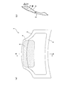
- FIG. 1 of FIGS. 1 to 4 shows a hood 1 (porous sound absorbing structure) of the first embodiment.
- 1A is a view of the hood 1 as viewed from the back
- FIG. 1B is a cross-sectional view taken along the line AA in FIG. 1A.
- the hood 1 includes an outer member 2 (outer member) having a smooth curved surface and an inner member 3 (inner member) having a concavo-convex shape. It is joined by means such as welding.
- a reinforcing plate material 4 is accommodated in the hollow portion S formed between the outer material 2 and the inner material 3.
- the reinforcing plate 4 is fixed to the surface on the hollow portion S side of the outer member 2 at the peripheral portion (edge portion).
- the outer material 2 of the hood 1 is a thin plate from the viewpoint of pedestrian protection, from the viewpoint of reducing the impact at the time of pedestrian collision, or from the viewpoint of weight reduction and cost reduction. For this reason, the reinforcing plate 4 is attached to the back surface of the outer material 2 so that the outer material 2 does not easily become depressed when a person holds it by hand.
- the material of the outer material 2, the inner material 3, and the reinforcing plate material 4 is aluminum or an aluminum alloy.
- a metal material such as iron may be used as the material for the outer material 2, the inner material 3, and the reinforcing plate material 4.
- the reinforcing plate 4 is substantially rectangular. Further, as shown in FIG. 1B, the cross-sectional shape of the reinforcing plate member 4 has two peak portions 4a and 4b, and a valley portion 4c having a predetermined width is formed between the peak portion 4a and the peak portion 4b. It has become. An air layer (back air layer) is formed between the mountain parts 4 a and 4 b and the valley part 4 c and the outer material 2.
- plate material 4 shown to Fig.1 (a) is an example. That is, the reinforcing plate material in the present invention is not limited to the shape of the present embodiment.
- the reinforcing plate member 4 may be fixed to the surface of the inner member 3 on the hollow portion S side instead of the outer member 2 in a form in which an air layer is formed between the reinforcing plate member 4 and the surface.
- plate material may be each fixed in the aspect by which the air layer was formed between the said surface in the surface by the side of the hollow part S of each of the outer material 2 and the inner material 3.
- a number of holes 5 are formed in the reinforcing plate member 4 to impart sound absorption in the hollow portion S.
- the sound absorption coefficient of the reinforcing plate member 4 is maximized at a specific frequency determined by the diameter of the holes 5, the pitch of the holes 5, and the distance between the reinforcing plate member 4 and the outer member 2 (the thickness of the back air layer).
- the thickness of the back air layer can be changed depending on the cross-sectional shape of the reinforcing plate 4.
- the diameter d 1 of the holes 5 (mm), it is preferable that there is a 0.7t 1 ⁇ d 1 ⁇ 1.3t 1 .
- t 1 (mm) is the thickness of the reinforcing plate 4.
- the thickness t 1 of the reinforcing plate 4 is about 0.8 mm ⁇ t 1 ⁇ 1.2 mm.
- board thickness of the outer material 2 and the inner material 3 is also about 0.8 mm or more and 1.2 mm or less.
- the hole 5 is opened in the range which is not less than the intensity
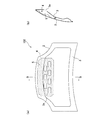
- FIG. 2 shows the hood 102 of the second embodiment.
- 2A is a view of the hood 102 as viewed from the back side
- FIG. 2B is a cross-sectional view taken along the line BB in FIG. 2A.
- 2 (a) and 2 (b) members similar to those of the hood 1 of the first embodiment are denoted by the same reference numerals (the same applies to other embodiments).
- the difference between the hood 102 and the hood 1 shown in FIGS. 1A and 1B is that an opening 3 a is provided in the inner material 3 in the hood 102.
- the engine is positioned with the hood 102 closed on the back side of the hood 102, on the right side of the hood 102 in FIG. 2B.
- the opening 3a is for guiding the sound (sound wave) generated by the engine to the reinforcing plate 4 in which a large number of holes 5 in the hollow portion S are formed.
- the opening 3 a is provided at a position facing the reinforcing plate 4 so that sound (sound wave) is easily guided to the reinforcing plate 4.
- the plurality of openings 3a are arranged in a zigzag manner (staggered arrangement). In this example, a plurality of openings 3a are provided in the inner material 3, but the number of openings 3a may be one.
- the shape of the opening 3a is not limited to a rectangle.
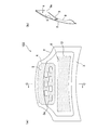
- FIG. 3 shows the hood 103 of the third embodiment.
- 3A is a view of the hood 103 as viewed from the back
- FIG. 3B is a cross-sectional view taken along the line CC of FIG. 3A.
- the difference between the hood 103 and the hood 102 shown in FIGS. 2A and 2B is that, in the hood 103, not only the reinforcing plate 4 but also the inner material 3 can have a large number of holes 6 (through holes). Thus, sound absorption is imparted to the inner material 3 itself.
- the reinforcing plate 4 in which a large number of holes 5 are formed is disposed at the front portion of the hood 103 in a plan view of the hood 103.
- the opening 3 a is also provided on the front side of the hood 103 (inner material 3) according to the reinforcing plate 4.
- the position of the sound absorbing portion 12 (the region where the hole 6 is opened) formed in the inner material 3 itself is located behind the reinforcing plate 4 and the opening 3a. That is, the position of the sound absorbing portion 12 is set behind the center of the hood 103 (inner material 3). In this manner, the reinforcing plate 4 and the sound absorbing portion 12 are shifted from each other and viewed from the engine (sound source) so that they do not overlap.
- the reinforcing plate member 4 and the sound absorbing portion 12 are shifted from each other when viewed from the engine (sound source), the air layer on the back side of the porous plate portion (the reinforcing plate member 4, the sound absorbing portion 12) is more suitable for sound absorption. It becomes. This is because the sound absorbing portion 12 can reliably close the opposing surface on the back side of the porous plate portion. In addition, sound from the engine (sound source) is easily introduced into each porous plate portion (reinforcing plate material 4, sound absorbing portion 12). As a result, the sound absorption is further improved.
- the position of the opening 3a is more preferably closer to the front end (one end) of the hood 103 (inner material 3) than the position shown in FIG. Thereby, the distance between the opening part 3a and the sound absorption part 12 becomes large.
- the distance between the opening 3a and the sound absorbing portion 12 is large, the influence of the opening 3a on the sound absorbing performance of the sound absorbing portion 12 is reduced.
- the distance between the sound absorbing portion 12 and the opening 3a is short, the air behind the sound absorbing portion 12 easily enters and exits from the opening 3a, so that the effective back air layer becomes large and the sound absorbing performance of the designed sound absorbing portion 12 can be exhibited. Disappear.
- the opening 3a and the sound absorbing portion 12 are separated as long as possible.
- the diameter d 2 of the holes 6 (mm) is the thickness of the inner material 3.
- T 2 (mm) is the thickness of the inner material 3. The relationship between the hole diameter and the plate thickness is the same when the outer material 2 is provided with holes for imparting sound absorption.
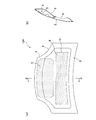
- FIG. 4 shows the hood 104 of the fourth embodiment.
- 4A is a view of the hood 104 viewed from the back
- FIG. 4B is a cross-sectional view taken along the line DD in FIG. 4A.
- the difference between the hood 104 and the hood 103 shown in FIGS. 3A and 3B is that the inner member 3 of the hood 104 is provided with an opening 3 a for guiding sound (sound wave) to the reinforcing plate 4. That is not the point.
- the other structure of the hood 104 is the same as that of the hood 103.
- FIG. 5 is a diagram showing an example in which the porous sound absorbing structure of the present invention is applied to a door of an automobile.
- FIG. 5 is a cross-sectional view of an automobile door.
- the door 51 includes an outer member 7 (outer member) having a smooth curved surface and an inner member 8 (inner member) having a concavo-convex shape by means of welding or the like around each other. It is formed by joining.
- a window glass 9 is accommodated in the hollow portion S formed between the outer material 7 and the inner material 8.
- the reinforcing plate 10 having a large number of holes 10a is formed on the surface of the outer member 7 on the side of the hollow portion S in such a manner that an air layer (back air layer) is formed between the outer material 7 and the surface. It is fixed. Further, the reinforcing plate 11 having a large number of holes 11a (through holes) is fixed to the surface on the hollow portion S side of the inner material 8 in such a manner that an air layer (back air layer) is formed between the inner material 8 and the surface.
- the reinforcing plate 11 having a large number of holes 11a is fixed to the surface on the hollow portion S side of the inner material 8 in such a manner that an air layer (back air layer) is formed between the inner material 8 and the surface.
- the sound absorption coefficient of the reinforcing plate 10 (11) includes the diameter of the holes 10a (11a), the pitch of the holes 10a (11a), and the distance between the reinforcing plate 10 (11) and the outer material 7 (inner material 8) (back air). Maximum at a certain frequency determined by the layer thickness). The thickness of the back air layer can be changed depending on the cross-sectional shape of the reinforcing plate 10 (11).
- the material of the outer material 7, the inner material 8, the reinforcing plate material 10, and the reinforcing plate material 11 is aluminum or an aluminum alloy like the hood. Other metals such as iron may be used.
- Reinforcing plate members 10 and 11 absorb, for example, sound emitted from the inside of the vehicle, such as sound from in-vehicle audio, and sound that enters the vehicle from the outside, such as road noise and wind noise.
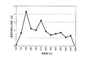
- FIG. 6 is a graph showing the sound insulation of the hood 1 shown in FIGS.
- the reinforcing plate member 4 having a large number of holes 5 to the surface of the outer member 2 on the side of the hollow portion S, the sound absorption with a smaller thickness of the back air layer is easier than before.
- a structure can be formed, and a frequency range with a large sound absorption coefficient can be easily expanded. Thereby, the sound emitted from the engine room through the hood to the outside of the vehicle can be reduced.
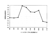
- FIG. 7 is a graph showing the sound absorption of the hood 102 shown in FIGS. 2 (a) and 2 (b).
- the sound absorption coefficient of the hood 102 the sound absorption coefficient of sound of 1 kHz to 2 kHz is increased by adjusting the air layer behind the reinforcing plate 4, the hole diameter, the opening ratio of the holes, and the like.
- the sound absorbing effect of the reinforcing plate 4 is further improved. Demonstrated.
- FIG. 8 is a graph showing the sound absorption of the hood 103 shown in FIGS. 3 (a) and 3 (b).
- the back air layer, hole diameter, hole opening ratio, etc. of the reinforcing plate 4 are adjusted so that the sound absorbing coefficient of sound of 1 kHz to 2 kHz is increased by the reinforcing plate 4.
- the hole diameter of the sound absorbing portion 12 of the inner material 3, the aperture ratio of the hole, etc. are adjusted so that the sound absorbing portion 12 can increase the sound absorption rate of the sound of 1.25 kHz to 3.15 kHz.
- the inner sound 3 is provided with a porous sound absorbing portion 12, so that the sound absorbing effect by the reinforcing plate 4 is obtained.
- the sound absorption effect by the inner material 3 itself can be obtained. Thereby, sound absorption performance can be improved in a wider frequency range.
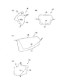
- FIG. 9 is a perspective view showing the side body 100 of the automobile.
- FIGS. 10A, 10B, 10C, and 10D are cross-sectional views of the side body 100 taken along line AA, BB, CC, and DD, respectively, shown in FIG. is there.
- FIG. 10A is a cross-sectional view of the front pillar 41 of the side body 100.
- the front pillar 41 is formed by joining an outer member 21 (outer member) having a smooth curved shape and an inner member 22 (inner member) having a concavo-convex shape by means of welding or the like around each other.
- a reinforcing plate member 23 having a large number of holes 23a (through holes) is fixed to the surface on the hollow portion side of the outer member 21 in such a manner that an air layer (back air layer) is formed between the outer member 21 and the surface. .
- sound absorption is provided in the hollow portion between the outer member 21 and the inner member 22.
- FIG. 10B is a cross-sectional view of the center pillar 42 of the side body 100. Similar to the front pillar 41 described above, the center pillar 42 includes an outer member 24, an inner member 25, and a reinforcing plate member 26 having a large number of through holes. The reinforcing plate member 26 provides sound absorption in the hollow portion between the outer member 24 and the inner member 25.
- FIG. 10C is a cross-sectional view of the rear pillar 43 of the side body 100.
- the rear pillar 43 includes an outer member 27, an inner member 28, and a reinforcing plate member 29 having a large number of through holes.
- the reinforcing plate material 29 provides sound absorption in the hollow portion between the outer material 27 and the inner material 28.
- FIG. 10D is a cross-sectional view of the side sill 44 of the side body 100.
- the side sill 44 includes an outer member 30, an inner member 31, and a reinforcing plate member 32 having a large number of through holes.
- the reinforcing plate member 32 provides sound absorption in the hollow portion between the outer member 30 and the inner member 31.
- the porous sound absorbing structure of the present invention can be applied to various parts constituting an automobile.
- engine sound, road noise, wind noise, vehicle interior resonance, and the like can be reduced.
- the space in the passenger compartment is as large as possible, so it is difficult to add new parts around the passenger compartment. Therefore, it is difficult to add new parts such as a sound absorbing material.
- sound absorbing properties are expressed by making holes in parts that are originally required as reinforcing members from the viewpoint of securing strength. That is, according to the present invention, the soundproof performance can be improved without adding new parts.
- the reinforcing plate is positioned between the outer member (outer member) and the inner member (inner member). Therefore, the thickness of the back air layer of the reinforcing plate is smaller than that of the back air layer of the porous inner material described in Patent Document 1, for example, under the same conditions. If the thickness of the back air layer is reduced, the reinforcing plate member having a large number of through holes absorbs a higher frequency sound as much as the thickness of the back air layer is reduced.
- the original function (role) of the reinforcing plate is to reinforce the outer material and / or the inner material.
- this reinforcing plate it is possible to easily impart sound absorption to the object without adding a new member for imparting sound absorption to the object.
- the outer material and / or the inner material is provided with an opening for guiding the sound wave to the reinforcing plate in the hollow portion between the outer material and the inner material. According to this configuration, sound waves are easily introduced into the reinforcing plate material, and the sound absorbing effect by the reinforcing plate material is enhanced.
- the hole diameter d (mm) is 0.7 t ⁇ d ⁇ 1 when the thickness of the plate member to be subjected to the porous processing is t (mm). .3t is preferable.
- the thickness t of the plate material is about 0.8 mm ⁇ t ⁇ 1.2 mm.
Landscapes
- Physics & Mathematics (AREA)
- Acoustics & Sound (AREA)
- Engineering & Computer Science (AREA)
- Mechanical Engineering (AREA)
- Multimedia (AREA)
- Architecture (AREA)
- Electromagnetism (AREA)
- Civil Engineering (AREA)
- Structural Engineering (AREA)
- Vehicle Interior And Exterior Ornaments, Soundproofing, And Insulation (AREA)
- Superstructure Of Vehicle (AREA)
- Soundproofing, Sound Blocking, And Sound Damping (AREA)
Description
本発明は、吸音性を有する多孔吸音構造に関する。さらには、本発明は、自動車を構成する部品に好適に適用される多孔吸音構造に関する。
この種の技術は、例えば特許文献1に記載されている。特許文献1に記載の吸音構造は、繊維質材と多孔板とを互いが重なるように設けるとともに、この多孔板または繊維質材の背後に空気層を設けている。繊維質材の密度ρ(kg/m3)、繊維質材の厚さt(mm)が、ρ×t≧0.01kg/m2の関係を満足することが良いとされている。
特許文献1に記載の吸音構造を例えば自動車のフード(ボンネットとも言う)に適用する場合、フードのインナー材(多孔板)の下面(エンジン側)に繊維質材(繊維系吸音材)を取り付けることになる(特許文献1の図1参照)。
一方、歩行者保護(衝撃吸収)の観点では、インナー材とエンジンとの間の距離を広くとることが衝撃吸収性能向上に繋がる。そのため、インナー材の下面に繊維系吸音材を取り付けることでエンジンルーム内のスペースを減らすことは可能な限り避けることが望ましい。
ここで、インナー材(多孔板)の吸音率は、その孔径・孔ピッチ・インナー材とアウター材との間の距離(空気層の厚さ)によって決まるある特定の周波数で最大となる。インナー材とアウター材との間の距離が比較的大きいと、インナー材(多孔板)のみで高い周波数の音を吸音させにくい。これは、空気層の厚さが大きくなると低い周波数の音を吸音するインナー材(多孔板)となるからである。なお、インナー材とアウター材との間の距離は、通常、吸音性付与を優先して決定できるものではない。
そのため、特許文献1に記載の吸音構造では、繊維質材(繊維系吸音材)により、例えば1kHz以上の高い周波数の音を吸音させる。そのため、エンジンルーム内のスペースを減らさないために、インナー材の下面から繊維系吸音材を単に取ってしまうと、高周波数の音の吸音性が低くなってしまう懸念がある。
本発明は、上記事情に鑑みてなされたものであって、その目的は、インナー材(内側材)の下面に繊維系吸音材を取り付けることなく、吸音率が大きい周波数範囲を容易に広げることができる多孔吸音構造を提供することである。
本発明は、滑らかな曲面形状を有する外側材と、前記外側材と周囲同士が結合されたことで前記外側材との間に中空部が形成された、凹凸形状を有する内側材と、前記外側材および前記内側材の少なくともいずれかの前記中空部側の面に当該面との間に空気層が形成されるように取り付けられた、多数の貫通孔を有する補強板材とを備える多孔吸音構造である。この多孔吸音構造は、前記補強板材により前記中空部内に吸音性が付与されている。
補強板材は、外側材(アウター材)と内側材(インナー材)との間に位置する。そのため、補強板材の背後空気層の厚さは、例えば特許文献1に記載の多孔板(インナー材)の背後空気層の厚さよりも同条件で比較して小さくなる。背後空気層の厚さを小さくすれば、多数の貫通孔を有する補強板材は、背後空気層の厚さを小さくした分、より高い周波数の音を吸音するようになる。
また、補強板材のそもそもの機能(役割)は、外側材および/または内側材の補強である。補強板材を利用することで、吸音性付与のための新たな部材を対象物に追加することなしに、すなわち、容易に対象物に吸音性を持たせることができる。
このように、本発明によれば、インナー材(内側材)の下面に繊維系吸音材を取り付けることなく、吸音率が大きな周波数範囲を容易に広げることができる。
また、補強板材のそもそもの機能(役割)は、外側材および/または内側材の補強である。補強板材を利用することで、吸音性付与のための新たな部材を対象物に追加することなしに、すなわち、容易に対象物に吸音性を持たせることができる。
このように、本発明によれば、インナー材(内側材)の下面に繊維系吸音材を取り付けることなく、吸音率が大きな周波数範囲を容易に広げることができる。
以下、本発明を実施するための形態について図面を参照しつつ説明する。以下では、本発明の多孔吸音構造を、自動車を構成する部品に適用した場合の例を示している。なお、本発明の適用対象は自動車を構成する部品に限られるものではない。
(フード(第1実施形態))
図1~4は、本発明の多孔吸音構造を自動車のフード(ボンネットとも言う)に適用した場合の例を示す図である。図1~4のうちの図1は、第1実施形態のフード1(多孔吸音構造体)を示す。図1(a)は、フード1を裏から視た図であり、図1(b)は、図1(a)のA-A断面図である。
図1~4は、本発明の多孔吸音構造を自動車のフード(ボンネットとも言う)に適用した場合の例を示す図である。図1~4のうちの図1は、第1実施形態のフード1(多孔吸音構造体)を示す。図1(a)は、フード1を裏から視た図であり、図1(b)は、図1(a)のA-A断面図である。
図1(a)(b)に示すように、フード1は、滑らかな曲面形状を有するアウター材2(外側材)と、凹凸形状を有するインナー材3(内側材)とが相互の周囲部で溶接などの手段で接合されてなるものである。
アウター材2とインナー材3との間に形成された中空部Sには、補強板材4が収容されている。補強板材4は、その周囲部分(縁部分)でアウター材2の中空部S側の面に固定されている。
フード1のアウター材2は、歩行者保護の観点から、歩行者の衝突時の衝撃を緩和するため、または軽量化・低コスト化の観点などから、薄板とされる。そのため、人が手で押さえたときにアウター材2が容易にへこまないように、アウター材2の裏面に補強板材4が取り付けられる。
アウター材2、インナー材3、補強板材4の材質は、アルミニウムまたはアルミニウム合金である。なお、アウター材2、インナー材3、補強板材4の材料として鉄などの金属材料を用いてもよい。
図1(a)に示したように、本例では、補強板材4は略長方形とされている。また、図1(b)に示したように、補強板材4の断面形状は、2つの山部4a,4bを有し、山部4aと山部4bとの間は所定幅の谷部4cとなっている。山部4a,4b、および谷部4cと、アウター材2との間には空気層(背後空気層)が形成されている。なお、図1(a)に示した補強板材4の形状は一例である。すなわち、本発明における補強板材は、本実施形態の形状のものに限られるものではない。
また、補強板材4は、アウター材2ではなく、インナー材3の中空部S側の面に、当該面との間に空気層が形成された態様で固定されていてもよい。さらには、アウター材2およびインナー材3のそれぞれの中空部S側の面に当該面との間に空気層が形成された態様で、それぞれ、補強板材が固定されていてもよい。
本発明では、この補強板材4に多数の孔5(貫通孔)を開けて、中空部S内に吸音性を付与している。補強板材4の吸音率は、孔5の径、孔5のピッチ、補強板材4とアウター材2との間の距離(背後空気層の厚さ)によって決まるある特定の周波数で最大となる。なお、背後空気層の厚さは、補強板材4の断面形状により変化させることができる。
量産性の観点から、孔5の径d1(mm)は、0.7t1≦d1≦1.3t1とされていることが好ましい。なお、t1(mm)は、補強板材4の板厚である。補強板材4の板厚t1は、0.8mm≦t1≦1.2mm程度である。なお、アウター材2およびインナー材3の板厚も、0.8mm以上、1.2mm以下程度である。また、孔5は、補強板材4が有するべき強度を下回らない範囲で開けられる。すなわち、孔5の数、そのピッチは、補強板材4の強度を考慮して決められる。
(フード(第2実施形態))
図2は、第2実施形態のフード102を示す。図2(a)は、フード102を裏から視た図であり、図2(b)は、図2(a)のB-B断面図である。図2(a)(b)において、第1実施形態のフード1と同様の部材には同じ符号を付している(他の実施形態についても同様)。
図2は、第2実施形態のフード102を示す。図2(a)は、フード102を裏から視た図であり、図2(b)は、図2(a)のB-B断面図である。図2(a)(b)において、第1実施形態のフード1と同様の部材には同じ符号を付している(他の実施形態についても同様)。
フード102と、図1(a)(b)に示したフード1との相違点は、フード102においてインナー材3に開口部3aが設けられている点である。
フード102の裏面側、図2(b)でいうとフード102の右側には、フード102が閉じられた状態でエンジンが位置する。開口部3aは、中空部S内の多数の孔5があけられた補強板材4へ、エンジンが発する音(音波)を導くためのものである。本実施形態では、この開口部3aは、補強板材4へ音(音波)が導かれやすいように、補強板材4と対向する位置に設けられている。また、複数の開口部3aはジグザグに配置されている(千鳥状配置とされている)。なお、この例では複数の開口部3aがインナー材3に設けられているが、開口部3aは1つであってもよい。開口部3aの形状は矩形に限られるものではない。
(フード(第3実施形態))
図3は、第3実施形態のフード103を示す。図3(a)は、フード103を裏から視た図であり、図3(b)は、図3(a)のC-C断面図である。
図3は、第3実施形態のフード103を示す。図3(a)は、フード103を裏から視た図であり、図3(b)は、図3(a)のC-C断面図である。
フード103と、図2(a)(b)に示したフード102との相違点は、フード103では、補強板材4だけでなく、インナー材3にも多数の孔6(貫通孔)が開けられて、インナー材3自体に吸音性が付与されている点である。
ここで、多数の孔5が開けられた補強板材4は、フード103の平面視においてフード103の前部に配置されている。開口部3aも補強板材4に合わせてフード103(インナー材3)の前部側に設けられている。これに対して、インナー材3自体に形成された吸音部12(孔6が開けられている領域)の位置は、補強板材4、開口部3aよりも後方とされている。すなわち、吸音部12の位置は、フード103(インナー材3)の中央よりも後方とされている。このような態様で、エンジン(音源)からみて、補強板材4と吸音部12とが相互にずらされ、重ならない位置とされている。
補強板材4と吸音部12とがエンジン(音源)からみて相互にずらされていることで、多孔板部(補強板材4、吸音部12)の裏側の空気層がより吸音に適した背後空気層となる。これは、吸音部12については、多孔板部の裏側の対向面を確実に閉ざすことができるからである。また、それぞれの多孔板部(補強板材4、吸音部12)にエンジン(音源)からの音が導入されやすくなる。これらにより、より吸音性が向上する。
なお、開口部3aの位置は、図3に示された位置よりも、フード103(インナー材3)の前側端部(一方の端部)に寄せられていると、さらに好ましい。これにより、開口部3aと吸音部12との間の距離が大きくなる。開口部3aと吸音部12との間の距離が大きいと、吸音部12の吸音性能に開口部3aの影響が少なくなる。吸音部12と開口部3aとの距離が近くなると吸音部12の背後空気が開口部3aから出入りし易くなるため、有効な背後空気層が大きくなり、設計した吸音部12の吸音性能が発揮できなくなる。これに対して、吸音部12と開口部3aとの距離を大きくすることにより、吸音部12の背後空気層への開口部3aの影響が小さくなり、その結果、設計した吸音部12の吸音性能を効率良く発揮することができる。これにより、フード103全体として吸音性がさらに向上する。このように、開口部3aと吸音部12とはできるだけ長い距離、離されていることが好ましい。
量産性の観点から、孔6の径d2(mm)は、0.7t2≦d2≦1.3t2とされていることが好ましい。なお、t2(mm)は、インナー材3の板厚である。孔径と板厚との関係は、吸音性を付与するための孔をアウター材2に開ける場合も同様である。
(フード(第4実施形態))
図4は、第4実施形態のフード104を示す。図4(a)は、フード104を裏から視た図であり、図4(b)は、図4(a)のD-D断面図である。
図4は、第4実施形態のフード104を示す。図4(a)は、フード104を裏から視た図であり、図4(b)は、図4(a)のD-D断面図である。
フード104と、図3(a)(b)に示したフード103との相違点は、フード104のインナー材3には、補強板材4に音(音波)を導くための開口部3aが設けられていない点である。フード104のその他の構造は、フード103と同じである。
(ドア)
図5は、本発明の多孔吸音構造を自動車のドアに適用した場合の一例を示す図である。なお、図5は自動車のドアの断面図である。
図5は、本発明の多孔吸音構造を自動車のドアに適用した場合の一例を示す図である。なお、図5は自動車のドアの断面図である。
図5に示すように、ドア51は、滑らかな曲面形状を有するアウター材7(外側材)と、凹凸形状を有するインナー材8(内側材)とが、相互の周囲部で溶接などの手段で接合されてなるものである。アウター材7とインナー材8との間に形成された中空部Sには、窓ガラス9が収容されるようになっている。
ここで、アウター材7の中空部S側の面には、当該面との間に空気層(背後空気層)が形成される態様で、多数の孔10a(貫通孔)を有する補強板材10が固定されている。
また、インナー材8の中空部S側の面には、当該面との間に空気層(背後空気層)が形成される態様で、多数の孔11a(貫通孔)を有する補強板材11が固定されている。
また、インナー材8の中空部S側の面には、当該面との間に空気層(背後空気層)が形成される態様で、多数の孔11a(貫通孔)を有する補強板材11が固定されている。
補強板材10(11)の吸音率は、孔10a(11a)の径、孔10a(11a)のピッチ、補強板材10(11)とアウター材7(インナー材8)との間の距離(背後空気層の厚さ)によって決まるある特定の周波数で最大となる。なお、背後空気層の厚さは、補強板材10(11)の断面形状により変化させることができる。
アウター材7、インナー材8、補強板材10、補強板材11の材質は、フードと同様に、アルミニウムまたはアルミニウム合金である。なお、鉄などの他の金属であってもよい。
補強板材10,11は、例えば車載オーディオからの音など、車内から車外へ放出される音、及びロードノイズ、風きり音など車外から車内へ入ってくる音を吸収する。
(放出音低減効果の解析結果)
図6は、図1(a)(b)に示したフード1の遮音性を示すグラフである。図6からわかるように、アウター材2の中空部S側の面に、多数の孔5が開けられた補強板材4を取り付けたことで、従来よりも容易に背後空気層の厚さの小さい吸音構造を形成することができ、吸音率が大きな周波数範囲を容易に広げることができる。これにより、エンジンルームからフードを経由して車外へ放出される音を低減することができる。
図6は、図1(a)(b)に示したフード1の遮音性を示すグラフである。図6からわかるように、アウター材2の中空部S側の面に、多数の孔5が開けられた補強板材4を取り付けたことで、従来よりも容易に背後空気層の厚さの小さい吸音構造を形成することができ、吸音率が大きな周波数範囲を容易に広げることができる。これにより、エンジンルームからフードを経由して車外へ放出される音を低減することができる。
図7は、図2(a)(b)に示したフード102の吸音性を示すグラフである。フード102の吸音率設計では、補強板材4の背後空気層・孔径・孔の開口率などを調整し、1kHz~2kHzの音の吸音率が高くなるようにしている。図7からわかるように、インナー材3の、補強板材4が対向する面に、当該補強板材4に音(音波)を導くための開口部3aを設けることにより、補強板材4による吸音効果がより発揮される。
図8は、図3(a)(b)に示したフード103の吸音性を示すグラフである。フード103の吸音率設計では、補強板材4の背後空気層、孔径、孔の開口率などを調整し、当該補強板材4により1kHz~2kHzの音の吸音率が高くなるようにしている。また、インナー材3の吸音部12の孔径、孔の開口率などを調整し、当該吸音部12により1.25kHz~3.15kHzの音の吸音率が高くなるようにしている。図8からわかるように、補強板材4が対向する部分のインナー材3に開口部3aを設けることに加えて、インナー材3自体に多孔の吸音部12を設けることで、補強板材4による吸音効果に加え、インナー材3自体による吸音効果も得られる。これにより、より幅広い周波数範囲で吸音性能を向上させることができる。
(自動車を構成するフード・ドア以外の部品への適用)
図9は、自動車のサイドボディ100を示す斜視図である。図10(a)(b)(c)(d)は、それぞれ、図9に示すサイドボディ100のA-A断面図、B-B断面図、C-C断面図、D-D断面図である。
図9は、自動車のサイドボディ100を示す斜視図である。図10(a)(b)(c)(d)は、それぞれ、図9に示すサイドボディ100のA-A断面図、B-B断面図、C-C断面図、D-D断面図である。
図10(a)は、サイドボディ100のフロントピラー41の断面図である。フロントピラー41は、滑らかな曲面形状を有するアウター材21(外側材)と、凹凸形状を有するインナー材22(内側材)とが相互の周囲部で溶接などの手段で接合されてなるものである。アウター材21の中空部側の面には、当該面との間に空気層(背後空気層)が形成される態様で、多数の孔23a(貫通孔)を有する補強板材23が固定されている。この補強板材23により、アウター材21とインナー材22との間の中空部内に吸音性が付与されている。
図10(b)は、サイドボディ100のセンターピラー42の断面図である。前記したフロントピラー41と同様に、センターピラー42は、アウター材24と、インナー材25と、多数の貫通孔を有する補強板材26とを備えている。補強板材26により、アウター材24とインナー材25との間の中空部内に吸音性が付与されている。
図10(c)は、サイドボディ100のリヤピラー43の断面図である。リヤピラー43に関しても同様に、リヤピラー43は、アウター材27と、インナー材28と、多数の貫通孔を有する補強板材29とを備えている。補強板材29により、アウター材27とインナー材28との間の中空部内に吸音性が付与されている。
図10(d)は、サイドボディ100のサイドシル44の断面図である。サイドシル44に関しても同様に、サイドシル44は、アウター材30と、インナー材31と、多数の貫通孔を有する補強板材32とを備えている。補強板材32により、アウター材30とインナー材31との間の中空部内に吸音性が付与されている。
このように、本発明の多孔吸音構造は、自動車を構成する様々な部品に適用することができる。そして、本発明の多孔吸音構造を適用することで、エンジン音、ロードノイズ、風きり音、車室内共鳴などを低減することができる。
ここで、車室内の空間はできるだけ大きなものであることが望ましいので、新たな部品を車室まわりに追加することはスペース的に厳しい。そのため、吸音材などの新たな部品の追加は難しい。これに対して本発明では、強度確保の観点から補強部材としてそもそも必要となる部品に孔を開けることで吸音性を発現させている。すなわち、本発明によると、新たな部品を追加することなく防音性能を向上させることができる。
(作用・効果)
以上、多くの例を示して説明したように、本発明の多孔吸音構造では、補強板材は、外側材(アウター材)と内側材(インナー材)との間に位置する。そのため、補強板材の背後空気層の厚さは、例えば特許文献1に記載の多孔インナー材の背後空気層の厚さよりも同条件で比較して小さくなる。背後空気層の厚さを小さくすれば、多数の貫通孔を有する補強板材は、背後空気層の厚さを小さくした分、より高い周波数の音を吸音するようになる。
以上、多くの例を示して説明したように、本発明の多孔吸音構造では、補強板材は、外側材(アウター材)と内側材(インナー材)との間に位置する。そのため、補強板材の背後空気層の厚さは、例えば特許文献1に記載の多孔インナー材の背後空気層の厚さよりも同条件で比較して小さくなる。背後空気層の厚さを小さくすれば、多数の貫通孔を有する補強板材は、背後空気層の厚さを小さくした分、より高い周波数の音を吸音するようになる。
また、補強板材のそもそもの機能(役割)は、外側材および/または内側材の補強である。この補強板材を利用することで、吸音性付与のための新たな部材を対象物に追加することなしに、すなわち、容易に対象物に吸音性を持たせることができる。このように、本発明によれば、インナー材(内側材)の下面に繊維系吸音材を取り付けることなく、吸音率が大きな周波数範囲を容易に広げることができる。
ここで、本発明においては、外側材および/または内側材に、当該外側材と内側材との間の中空部内の補強板材に音波を導くための開口部が設けられていることが好ましい。この構成によると、補強板材に音波が導入されやすくなり、補強板材による吸音効果が高まる。
また、前記開口部が、補強板材と対向する位置に設けられていると、補強板材に音波がより導入されやすくなり、補強板材による吸音効果がさらに高まる。
さらに、補強板材だけでなく、外側材および/または内側材にも多数の貫通孔を開けることで、外側材および/または内側材自体にも吸音性を付与すると、補強板材による吸音効果に加え、外側材および/または内側材自体による、補強板材とは別の周波数域における吸音効果も得ることができる。これにより、より幅広い周波数範囲で吸音性能を向上させることができる。
なお、補強板材、内側材、外側材などに多孔加工を施す場合、孔の径d(mm)は、多孔加工を施す板材の厚さをt(mm)とすると、0.7t≦d≦1.3tとされていることが好ましい。なお、板材の厚さtは、0.8mm≦t≦1.2mm程度である。この範囲の大きさの孔径とすると、例えばパンチング加工の孔開けが容易に行え、量産性が向上する。
以上、本発明の実施形態について説明したが、本発明は上述の実施の形態に限られるものではなく、特許請求の範囲に記載した限りにおいて様々に変更して実施することが可能なものである。本出願は2012年9月4日出願の日本特許出願(特願2012-194106)に基づくものであり、その内容はここに参照として取り込まれる。
1:フード
2:アウター材(外側材)
3:インナー材(内側材)
4:補強板材
5:孔(貫通孔)
S:中空部
2:アウター材(外側材)
3:インナー材(内側材)
4:補強板材
5:孔(貫通孔)
S:中空部
Claims (5)
- 滑らかな曲面形状を有する外側材と、
前記外側材と周囲同士が結合されたことで前記外側材との間に中空部が形成された、凹凸形状を有する内側材と、
前記外側材および前記内側材の少なくともいずれかの前記中空部側の面に当該面との間に空気層が形成されるように取り付けられた、多数の貫通孔を有する補強板材と、
を備えており、
前記補強板材により前記中空部内に吸音性が付与されている、多孔吸音構造。 - 請求項1に記載の多孔吸音構造であって、
前記外側材および前記内側材の少なくともいずれかに、前記中空部内の前記補強板材に音波を導くための開口部が設けられている、多孔吸音構造。 - 請求項2に記載の多孔吸音構造であって、
前記開口部は、前記補強板材と対向する位置に設けられている、多孔吸音構造。 - 請求項1に記載の多孔吸音構造であって、
前記外側材および前記内側材の少なくともいずれかにも多数の貫通孔が開けられていることで、前記外側材および前記内側材の少なくともいずれか自体に吸音性が付与されている、多孔吸音構造。 - 請求項1~4のいずれか1項に記載の多孔吸音構造であって、
前記補強板材の板厚t1(mm)は、0.8≦t1≦1.2とされており、
前記補強板材に開けられる前記貫通孔の径d1(mm)は、0.7t1≦d1≦1.3t1とされている、多孔吸音構造。
Priority Applications (3)
| Application Number | Priority Date | Filing Date | Title |
|---|---|---|---|
| CN201380045776.9A CN104584117B (zh) | 2012-09-04 | 2013-08-28 | 多孔吸音构造 |
| US14/419,570 US9453336B2 (en) | 2012-09-04 | 2013-08-28 | Porous sound absorbing structure |
| US15/235,537 US10229665B2 (en) | 2012-09-04 | 2016-08-12 | Porous sound absorbing structure |
Applications Claiming Priority (2)
| Application Number | Priority Date | Filing Date | Title |
|---|---|---|---|
| JP2012194106A JP5918662B2 (ja) | 2012-09-04 | 2012-09-04 | 多孔吸音構造 |
| JP2012-194106 | 2012-09-04 |
Related Child Applications (3)
| Application Number | Title | Priority Date | Filing Date |
|---|---|---|---|
| US14/419,570 A-371-Of-International US9453336B2 (en) | 2012-09-04 | 2013-08-28 | Porous sound absorbing structure |
| US14/419,570 Continuation US9453336B2 (en) | 2012-09-04 | 2013-08-28 | Porous sound absorbing structure |
| US15/235,537 Continuation US10229665B2 (en) | 2012-09-04 | 2016-08-12 | Porous sound absorbing structure |
Publications (1)
| Publication Number | Publication Date |
|---|---|
| WO2014038445A1 true WO2014038445A1 (ja) | 2014-03-13 |
Family
ID=50237057
Family Applications (1)
| Application Number | Title | Priority Date | Filing Date |
|---|---|---|---|
| PCT/JP2013/072992 Ceased WO2014038445A1 (ja) | 2012-09-04 | 2013-08-28 | 多孔吸音構造 |
Country Status (4)
| Country | Link |
|---|---|
| US (2) | US9453336B2 (ja) |
| JP (1) | JP5918662B2 (ja) |
| CN (1) | CN104584117B (ja) |
| WO (1) | WO2014038445A1 (ja) |
Families Citing this family (6)
| Publication number | Priority date | Publication date | Assignee | Title |
|---|---|---|---|---|
| JP5918662B2 (ja) * | 2012-09-04 | 2016-05-18 | 株式会社神戸製鋼所 | 多孔吸音構造 |
| JP6165466B2 (ja) * | 2013-02-27 | 2017-07-19 | 株式会社神戸製鋼所 | 防音構造 |
| WO2015185320A1 (en) * | 2014-06-05 | 2015-12-10 | Asml Netherlands B.V. | Lithographic apparatus |
| US9251778B2 (en) | 2014-06-06 | 2016-02-02 | Industrial Technology Research Institute | Metal foil with microcracks, method of manufacturing the same, and sound-absorbing structure having the same |
| JP6330841B2 (ja) * | 2016-03-29 | 2018-05-30 | マツダ株式会社 | 保温カバーの取付構造 |
| JP6788828B2 (ja) * | 2016-09-16 | 2020-11-25 | スズキ株式会社 | 車両ルーフ部構造及び車両用ルーフパネルの製造方法 |
Citations (3)
| Publication number | Priority date | Publication date | Assignee | Title |
|---|---|---|---|---|
| JP2005099789A (ja) * | 2003-09-05 | 2005-04-14 | Kobe Steel Ltd | 吸音構造体およびその製造方法 |
| JP2007245853A (ja) * | 2006-03-15 | 2007-09-27 | Shinko Alcoa Yuso Kizai Kk | 自動車用フード |
| JP2012013912A (ja) * | 2010-06-30 | 2012-01-19 | Three M Innovative Properties Co | 吸音システム及びその作製方法 |
Family Cites Families (23)
| Publication number | Priority date | Publication date | Assignee | Title |
|---|---|---|---|---|
| US2159488A (en) * | 1935-08-01 | 1939-05-23 | Johns Manville | Perforated membrane |
| US2966954A (en) * | 1957-07-11 | 1961-01-03 | Celotex Corp | Acoustical correction element |
| JPS61249878A (ja) * | 1985-04-30 | 1986-11-07 | Mazda Motor Corp | 車両の吸音構造 |
| US5997985A (en) * | 1998-09-10 | 1999-12-07 | Northrop Grumman Corporation | Method of forming acoustic attenuation chambers using laser processing of multi-layered polymer films |
| ES2177513T3 (es) * | 1999-05-06 | 2002-12-16 | Faist Automotive Gmbh & Co Kg | Elemento de insonorizacion, utilizacion del mismo y procedimiento parasu fabricacion. |
| JP2003050586A (ja) * | 2000-09-29 | 2003-02-21 | Kobe Steel Ltd | 多孔質防音構造体およびその製造方法 |
| EP1408483A4 (en) * | 2001-06-21 | 2008-06-11 | Kobe Steel Ltd | POROUS SOUNDPROOF STRUCTURAL BODY AND METHOD FOR THE PRODUCTION THEREOF |
| JP4050632B2 (ja) * | 2003-02-24 | 2008-02-20 | 株式会社神戸製鋼所 | 吸音構造体 |
| JP2004264374A (ja) * | 2003-02-24 | 2004-09-24 | Kobe Steel Ltd | 薄膜を用いた吸音構造 |
| EP1662480A4 (en) | 2003-09-05 | 2013-01-23 | Kobe Steel Ltd | SOUND ABSORPTION STRUCTURE AND METHOD FOR THE PRODUCTION THEREOF |
| DE20320100U1 (de) * | 2003-12-23 | 2005-05-12 | Carcoustics Tech Center Gmbh | Luftschallabsorbierendes Bauteil |
| EP1742201A4 (en) | 2004-04-30 | 2017-07-19 | Kabushiki Kaisha Kobe Seiko Sho | Porous sound absorbing structure |
| JP4567513B2 (ja) * | 2004-04-30 | 2010-10-20 | 株式会社神戸製鋼所 | 多孔質吸音構造体 |
| ATE473903T1 (de) * | 2004-12-02 | 2010-07-15 | Kobe Steel Ltd | Wandstruktur für fahrzeugkarosserie |
| JP2006199276A (ja) | 2004-12-24 | 2006-08-03 | Kobe Steel Ltd | 吸音構造 |
| JP4754836B2 (ja) * | 2005-01-27 | 2011-08-24 | 株式会社神戸製鋼所 | 二重壁構造体 |
| JP2006281926A (ja) * | 2005-03-31 | 2006-10-19 | Kobe Steel Ltd | 車体トランクリッド用パネル構造体 |
| JP2007069816A (ja) * | 2005-09-08 | 2007-03-22 | Kobe Steel Ltd | 二重壁構造体 |
| JP2008009014A (ja) * | 2006-06-28 | 2008-01-17 | Kobe Steel Ltd | 多孔質防音構造体 |
| US8109361B2 (en) * | 2006-07-20 | 2012-02-07 | Kobe Steel, Ltd. | Solid-borne sound reducing structure |
| US20090197044A1 (en) * | 2008-02-04 | 2009-08-06 | Pelzer Acoustic Products, Llc | Absorptive Heat Shield |
| JP5459835B2 (ja) * | 2008-08-08 | 2014-04-02 | ニチアス株式会社 | 自動車用防音カバー |
| JP5918662B2 (ja) * | 2012-09-04 | 2016-05-18 | 株式会社神戸製鋼所 | 多孔吸音構造 |
-
2012
- 2012-09-04 JP JP2012194106A patent/JP5918662B2/ja not_active Expired - Fee Related
-
2013
- 2013-08-28 US US14/419,570 patent/US9453336B2/en not_active Expired - Fee Related
- 2013-08-28 CN CN201380045776.9A patent/CN104584117B/zh not_active Expired - Fee Related
- 2013-08-28 WO PCT/JP2013/072992 patent/WO2014038445A1/ja not_active Ceased
-
2016
- 2016-08-12 US US15/235,537 patent/US10229665B2/en active Active
Patent Citations (3)
| Publication number | Priority date | Publication date | Assignee | Title |
|---|---|---|---|---|
| JP2005099789A (ja) * | 2003-09-05 | 2005-04-14 | Kobe Steel Ltd | 吸音構造体およびその製造方法 |
| JP2007245853A (ja) * | 2006-03-15 | 2007-09-27 | Shinko Alcoa Yuso Kizai Kk | 自動車用フード |
| JP2012013912A (ja) * | 2010-06-30 | 2012-01-19 | Three M Innovative Properties Co | 吸音システム及びその作製方法 |
Also Published As
| Publication number | Publication date |
|---|---|
| JP2014048632A (ja) | 2014-03-17 |
| CN104584117B (zh) | 2018-09-14 |
| CN104584117A (zh) | 2015-04-29 |
| US10229665B2 (en) | 2019-03-12 |
| US20160351180A1 (en) | 2016-12-01 |
| US20150211226A1 (en) | 2015-07-30 |
| JP5918662B2 (ja) | 2016-05-18 |
| US9453336B2 (en) | 2016-09-27 |
Similar Documents
| Publication | Publication Date | Title |
|---|---|---|
| JP5918662B2 (ja) | 多孔吸音構造 | |
| US7654364B2 (en) | Sound absorbing structure | |
| US20060289229A1 (en) | Sound absorbing structure body and producing method thereof | |
| WO2012157100A1 (ja) | 車両用フード構造 | |
| WO2015125872A1 (ja) | 車体パネル構造体 | |
| JP2013535030A (ja) | 音減衰パッチ | |
| JP6165466B2 (ja) | 防音構造 | |
| JP5984930B2 (ja) | 自動車の組付けアッセンブリ | |
| EP1531115B1 (en) | Automotive floor panel structure | |
| US7104595B2 (en) | Automotive floor panel structure | |
| CN217835792U (zh) | 后轮罩组件、后侧围结构及车辆 | |
| JP6418203B2 (ja) | 車両の側部車体構造 | |
| JP6602655B2 (ja) | 鉄道車両および鉄道車両加工方法 | |
| JP2006142885A (ja) | 路上走行自動車の吸音構造 | |
| JP2006160177A (ja) | 路上走行自動車の吸音構造 | |
| US7134710B2 (en) | Automotive floor panel structure | |
| JP2002087179A (ja) | 自動車用内装部品 | |
| US20060065481A1 (en) | Perforated hard trim for sound absorption | |
| JP2018144776A (ja) | 内装パネル及び車両用内装パネル | |
| JP6889636B2 (ja) | 鉄道車両 | |
| JP4514567B2 (ja) | 自動車のパネル構造 | |
| Chopra et al. | Integrated Approach and Ideas for Designing Lightweight NVH Parts in Passenger Vehicle | |
| WO2006114196A1 (de) | Vorrichtung zur schallabsorption und -reduktion im fahrzeuginnenraum | |
| JP2015107667A (ja) | 車両用フードレゾネータ装置 | |
| JP2006315497A (ja) | 静音部材およびパネル部材 |
Legal Events
| Date | Code | Title | Description |
|---|---|---|---|
| 121 | Ep: the epo has been informed by wipo that ep was designated in this application |
Ref document number: 13835351 Country of ref document: EP Kind code of ref document: A1 |
|
| WWE | Wipo information: entry into national phase |
Ref document number: 14419570 Country of ref document: US |
|
| NENP | Non-entry into the national phase |
Ref country code: DE |
|
| 122 | Ep: pct application non-entry in european phase |
Ref document number: 13835351 Country of ref document: EP Kind code of ref document: A1 |