WO2014038127A1 - アキュムレータ - Google Patents
アキュムレータ Download PDFInfo
- Publication number
- WO2014038127A1 WO2014038127A1 PCT/JP2013/004700 JP2013004700W WO2014038127A1 WO 2014038127 A1 WO2014038127 A1 WO 2014038127A1 JP 2013004700 W JP2013004700 W JP 2013004700W WO 2014038127 A1 WO2014038127 A1 WO 2014038127A1
- Authority
- WO
- WIPO (PCT)
- Prior art keywords
- desiccant
- tank
- refrigerant
- phase refrigerant
- liquid
- Prior art date
- Legal status (The legal status is an assumption and is not a legal conclusion. Google has not performed a legal analysis and makes no representation as to the accuracy of the status listed.)
- Ceased
Links
Images
Classifications
-
- F—MECHANICAL ENGINEERING; LIGHTING; HEATING; WEAPONS; BLASTING
- F25—REFRIGERATION OR COOLING; COMBINED HEATING AND REFRIGERATION SYSTEMS; HEAT PUMP SYSTEMS; MANUFACTURE OR STORAGE OF ICE; LIQUEFACTION SOLIDIFICATION OF GASES
- F25B—REFRIGERATION MACHINES, PLANTS OR SYSTEMS; COMBINED HEATING AND REFRIGERATION SYSTEMS; HEAT PUMP SYSTEMS
- F25B43/00—Arrangements for separating or purifying gases or liquids; Arrangements for vaporising the residuum of liquid refrigerant, e.g. by heat
- F25B43/006—Accumulators
-
- B—PERFORMING OPERATIONS; TRANSPORTING
- B01—PHYSICAL OR CHEMICAL PROCESSES OR APPARATUS IN GENERAL
- B01D—SEPARATION
- B01D53/00—Separation of gases or vapours; Recovering vapours of volatile solvents from gases; Chemical or biological purification of waste gases, e.g. engine exhaust gases, smoke, fumes, flue gases, aerosols
- B01D53/02—Separation of gases or vapours; Recovering vapours of volatile solvents from gases; Chemical or biological purification of waste gases, e.g. engine exhaust gases, smoke, fumes, flue gases, aerosols by adsorption, e.g. preparative gas chromatography
- B01D53/04—Separation of gases or vapours; Recovering vapours of volatile solvents from gases; Chemical or biological purification of waste gases, e.g. engine exhaust gases, smoke, fumes, flue gases, aerosols by adsorption, e.g. preparative gas chromatography with stationary adsorbents
- B01D53/0407—Constructional details of adsorbing systems
-
- B—PERFORMING OPERATIONS; TRANSPORTING
- B01—PHYSICAL OR CHEMICAL PROCESSES OR APPARATUS IN GENERAL
- B01D—SEPARATION
- B01D2257/00—Components to be removed
- B01D2257/80—Water
-
- F—MECHANICAL ENGINEERING; LIGHTING; HEATING; WEAPONS; BLASTING
- F25—REFRIGERATION OR COOLING; COMBINED HEATING AND REFRIGERATION SYSTEMS; HEAT PUMP SYSTEMS; MANUFACTURE OR STORAGE OF ICE; LIQUEFACTION SOLIDIFICATION OF GASES
- F25B—REFRIGERATION MACHINES, PLANTS OR SYSTEMS; COMBINED HEATING AND REFRIGERATION SYSTEMS; HEAT PUMP SYSTEMS
- F25B2400/00—General features or devices for refrigeration machines, plants or systems, combined heating and refrigeration systems or heat-pump systems, i.e. not limited to a particular subgroup of F25B
- F25B2400/03—Suction accumulators with deflectors
-
- F—MECHANICAL ENGINEERING; LIGHTING; HEATING; WEAPONS; BLASTING
- F25—REFRIGERATION OR COOLING; COMBINED HEATING AND REFRIGERATION SYSTEMS; HEAT PUMP SYSTEMS; MANUFACTURE OR STORAGE OF ICE; LIQUEFACTION SOLIDIFICATION OF GASES
- F25B—REFRIGERATION MACHINES, PLANTS OR SYSTEMS; COMBINED HEATING AND REFRIGERATION SYSTEMS; HEAT PUMP SYSTEMS
- F25B2500/00—Problems to be solved
- F25B2500/12—Sound
-
- F—MECHANICAL ENGINEERING; LIGHTING; HEATING; WEAPONS; BLASTING
- F25—REFRIGERATION OR COOLING; COMBINED HEATING AND REFRIGERATION SYSTEMS; HEAT PUMP SYSTEMS; MANUFACTURE OR STORAGE OF ICE; LIQUEFACTION SOLIDIFICATION OF GASES
- F25B—REFRIGERATION MACHINES, PLANTS OR SYSTEMS; COMBINED HEATING AND REFRIGERATION SYSTEMS; HEAT PUMP SYSTEMS
- F25B2500/00—Problems to be solved
- F25B2500/26—Problems to be solved characterised by the startup of the refrigeration cycle
Definitions
- This disclosure relates to an accumulator used in a refrigeration cycle.
- the accumulator separates the refrigerant into a gas-phase refrigerant and a liquid-phase refrigerant, and sends the gas-phase refrigerant to the compressor constituting the refrigeration cycle.
- the accumulator includes a tank that separates the refrigerant that has flowed into the vapor phase refrigerant and the liquid phase refrigerant, and stores the liquid phase refrigerant therein.
- a desiccant is built in a tank in order to remove moisture in the refrigerant.
- the desiccant is disposed below the tank, and the entire desiccant is immersed in the liquid refrigerant.
- the desiccant is disposed above the maximum liquid surface position of the liquid refrigerant, so that the entire desiccant is not immersed in the liquid refrigerant.
- the desiccant is disposed over the entire cross section of the tank, and the desiccant is located directly below the refrigerant inlet of the gas-liquid mixed refrigerant. Further, a suction port for the gas-phase refrigerant is located above the desiccant.
- the present disclosure provides an accumulator capable of preventing both abnormal noise generation at the time of starting the compressor and suction of the liquid phase refrigerant from the suction port of the gas phase refrigerant due to the collision of the liquid phase refrigerant with the desiccant.
- the purpose is to provide.
- an accumulator includes a tank and a desiccant.
- the tank separates the refrigerant flowing into the inside into a gas phase refrigerant and a liquid phase refrigerant, stores the liquid phase refrigerant therein, and causes the gas phase refrigerant to flow out to the suction side of the compressor.
- the desiccant is placed in the tank to remove moisture in the refrigerant. Of the refrigerant flowing into the tank, the liquid-phase refrigerant falls downward from a position above the desiccant and is stored below the tank.
- the gas-phase refrigerant is sucked from the suction port located above the desiccant and flows out of the tank. Furthermore, normally, at least a part of the desiccant is exposed to the gas-phase refrigerant, and the desiccant is disposed at a position avoiding the falling path of the liquid-phase refrigerant.
- the inventors of the present application have examined measures against abnormal noise generation at the time of starting the compressor, and at the time of starting the compressor, not all of the desiccant was immersed in the liquid phase refrigerant, but a part of the desiccant. It has been found from experiments that the generation of the vibration of the tank at the start of the compressor can be prevented and the generation of abnormal noise can be prevented by setting the gas refrigerant out of the liquid phase refrigerant. Note that if the desiccant is not completely immersed in the liquid refrigerant when the compressor is started, the refrigerant will not boil starting from the desiccant, thus preventing abnormal noise when the compressor is started. it can.
- the desiccant is disposed at a position avoiding the dropping path of the liquid-phase refrigerant, it is possible to prevent the falling liquid-phase refrigerant from colliding with the desiccant, and from the gas-phase refrigerant suction port. Inhalation of liquid phase refrigerant can be prevented.
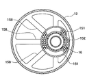
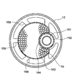
- FIG. 3 is a sectional view taken along the line III-III in FIG. 2. It is a vibration measurement result in the accumulator of 1st Embodiment and a comparative example. It is a longitudinal cross-sectional view of the accumulator in a comparative example. It is a longitudinal cross-sectional view of the accumulator in 2nd Embodiment. It is VII-VII sectional drawing of FIG. It is a longitudinal cross-sectional view of the accumulator in 3rd Embodiment.
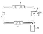
- the accumulator of this embodiment is applied to the refrigeration cycle of a vehicle air conditioner.
- the refrigeration cycle includes a compressor 1, a condenser 3, a decompression device 4, an evaporator 5, and an accumulator 10.
- Compressor 1 sucks and compresses refrigerant.
- the compressor 1 is rotationally driven by a vehicle travel engine (not shown) via a pulley 2, a belt, and the like.
- the compressor 1 can be a variable capacity compressor that can adjust the refrigerant discharge capacity by changing the discharge capacity, or a fixed capacity type compressor that adjusts the refrigerant discharge capacity by changing the operating rate of the compressor operation by switching the electromagnetic clutch. Any of the machines may be used. Further, if an electric compressor is used as the compressor 1, the refrigerant discharge capacity can be adjusted by adjusting the rotational speed of the electric motor.
- the high-pressure gas-phase refrigerant discharged from the compressor 1 flows into the condenser 3, where it is cooled and condensed by exchanging heat with the outside air.
- the liquid refrigerant condensed in the condenser 3 is then decompressed to a low pressure by the decompression device 4 to be in a mist-like gas-liquid two-phase state.
- the pressure reducing device 4 is composed of a fixed throttle such as an orifice and a nozzle, or an appropriate variable throttle.
- the low-pressure refrigerant after depressurization is evaporated in the evaporator 5 by absorbing heat from air blown from an air-conditioning blower (not shown).
- the evaporator 5 is disposed in an air conditioning case (not shown), and the cold air cooled by the evaporator 5 is adjusted in temperature by a heater core (not shown) and then blown out into the passenger compartment.
- the refrigerant that has passed through the evaporator 5 is separated into gas and liquid by the accumulator 10 and then sucked into the compressor 1.
- the accumulator 10 serves to separate the refrigerant flowing out of the evaporator 5 into a gas phase refrigerant and a liquid phase refrigerant, store the liquid phase refrigerant, and suck the gas phase refrigerant into the compressor 1.
- the accumulator 10 also serves to cause the compressor 1 to suck oil dissolved in the liquid refrigerant that accumulates on the tank bottom side.
- the accumulator 10 separates the refrigerant that has flowed into the vapor phase refrigerant and the liquid phase refrigerant, stores the liquid phase refrigerant therein, and flows the vapor phase refrigerant to the suction side of the compressor.
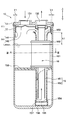
- a tank 11 is provided.
- the arrow which shows the up-down direction in FIG. 2 has shown the up-down direction of the accumulator 10 at the time of vehicle mounting.
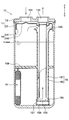
- the tank 11 is composed of a tank body 12 and a header 13 that closes the upper end of the tank body 12.
- the tank main body 12 and the header 13 are made of metal, and the upper end portion of the tank main body 12 and the header 13 are fixed by brazing.
- the tank main body 12 has a bottomed cylindrical shape with an open upper end, and contains an umbrella-shaped member 14, a suction pipe 15, and a desiccant 16 inside. Further, the separated liquid-phase refrigerant is stored in the lower portion of the tank body 12 and the lubricating oil is stored in a state of being dissolved in the liquid-phase refrigerant.
- the header 13 is formed in a flat cylindrical shape having the same diameter as the tank body 12.
- the header 13 is formed with a circular refrigerant inlet 131 and a refrigerant outlet 132 that open in the vertical direction.
- the refrigerant inflow port 131 is connected to the evaporator 5 via a pipe so that the refrigerant heat-exchanged by the evaporator 5 can flow into the tank body 12.
- the refrigerant outlet 132 is connected to the compressor 1 via a pipe so that the gas-phase refrigerant separated in the tank body 12 can flow out to the compressor 1.
- the umbrella-shaped member 14 is a collision member with which the refrigerant introduced vertically downward from the refrigerant inlet 131 collides.
- the umbrella-shaped member 14 has a cylindrical side wall portion 141 extending in the vertical direction and an upper wall portion 142 that closes the upper end side of the side wall portion 141, and the lower end side of the side wall portion 141 is open.
- the umbrella-shaped member 14 is disposed above the inside of the tank 11 so that the upper wall 142 can be seen when the tank body 12 is viewed from the refrigerant inlet 131.
- a portion of the upper wall portion 142 that faces the refrigerant inflow port 131 protrudes upward, and a portion of the upper wall portion 142 that faces the refrigerant outlet port 132 has an opening.
- the umbrella-shaped member 14 is made of metal, and is press-fitted and fixed to the lower surface of the header 13 with the opening formed in the upper wall 142 matching the refrigerant outlet 132. Further, the outer edge of the upper wall portion 142 is located in the vicinity of the inner wall of the tank body 12.
- the accumulator 10 of the present embodiment is a collision type that separates the liquid-phase refrigerant and the gas-phase refrigerant after colliding the refrigerant introduced from the refrigerant inlet 131 with the umbrella-shaped member 14. That is, the refrigerant that has collided with the upper wall portion 142 of the umbrella-shaped member 14 diffuses in the lateral direction of the tank 11 and is guided outside the outer edge of the upper wall portion 142 of the umbrella-shaped member 14 in the lateral direction of the tank 11. Then, the liquid phase refrigerant falls from outside the outer edge of the umbrella-shaped member 14, passes through the inner wall of the tank body 12, and accumulates below the tank body 12. The gas-phase refrigerant is sucked into the suction pipe 15 from below the umbrella-like member 14 and flows out of the tank 11.
- the suction pipe 15 is a double pipe type, and has an inner pipe 151 and an outer pipe 152.
- the inner pipe 151 and the outer pipe 152 are both constituted by straight pipes and are housed in the tank body 12 in an upright posture.
- the inner pipe 151 and the outer pipe 152 are coaxial so that the inner pipe 151 is coaxial.
- the inner pipe 151 is fixed to the lower surface of the header 13.
- the inner pipe 151 is made of metal, and the upper end portion of the inner pipe 151 is press-fitted and fixed to the lower surface of the header 13 with the opening thereof and the refrigerant outlet 132 aligned.
- the outer pipe 152 is fixed to the inner pipe 151.
- the outer pipe 152 is made of plastic, and a protruding portion (thick portion) (not shown) is provided on the inner wall surface.
- the outer pipe 152 is press-fitted and fixed by inserting the inner pipe 151 inside the projecting portion.
- the outer pipe 152 is in a state in which the upper end opening 153 that forms the suction port for the gas-phase refrigerant has entered the umbrella-like member 14 while having a predetermined gap with the upper wall 142 of the umbrella-like member 14. Yes.
- the outer pipe 152 has a lower end 154 closed, and an oil return hole 155 is formed at the bottom of the lower end 154.
- the oil return hole 155 is for sucking the lubricating oil stored in the lower part of the tank body 12 by the gas phase refrigerant flowing into the inner pipe 151 and allowing the oil pipe to pass through the inner pipe 151 together with the gas phase refrigerant.
- a filter cap 156 is attached to the outside of the lower end portion 154 of the outer pipe 152.
- the filter cap 156 is formed in a bottomed cylindrical shape, and a filter 157 for removing sludge and the like contained in oil is provided on the cylindrical side wall.
- a holding portion 158 for holding the desiccant 16 is disposed near the center of the outer pipe 152 in the vertical direction.
- the holding portion 158 is made of plastic and is integrally formed with the outer pipe 152.
- the holding portion 158 has a shape having a plurality of beams extending radially from the outer pipe 152 in the tank lateral direction.
- the holding part 158 may be separated from the outer pipe 152.
- the desiccant 16 is for removing moisture in the refrigerant, and is a particle of zeolite or the like as shown in FIG.
- the bag 161 is a desiccant container that is made of cloth such as felt and has flexibility and also functions as a filter.
- the bag 161 in which the desiccant 16 is accommodated is bound and fixed by a string-like fixing portion 162 such as a binding band in a state of being wound around the suction pipe 15.
- the desiccant 16 is located on the inner side of the outer edge of the umbrella-shaped member 14 in the lateral direction of the tank 11 and does not protrude beyond the outer edge of the umbrella-shaped member 14.
- the desiccant 16 is located in the region directly below the umbrella-like member 14 and is located at a position away from the inner wall of the tank 11 by a predetermined distance or more. This predetermined distance is an interval Y1 between the umbrella-shaped member 14 and the inner wall of the tank 11.
- the desiccant 16 is liquid when the upper end of the desiccant 16 is located below the suction port 153 and the liquid phase refrigerant is most accumulated in the tank 11 so as not to interfere with the suction port 153 of the outer pipe 152. It is installed so as to be located above the surface position (maximum liquid surface position) Lmax. That is, a part of the desiccant 16 is always exposed to the gas phase refrigerant.
- the maximum liquid level position here is the maximum liquid level position when the compressor 1 is stopped.
- the highest liquid level position is defined by the amount of refrigerant enclosed in the entire refrigeration cycle.
- the amount of refrigerant charged increases depending on the size of the refrigeration cycle, but in actual use, the amount of sealed liquid of about 1000 g is the maximum, and the liquid level at this time is the tank used by the inventor for the test.
- 11 has been confirmed by the test to be about 150 mm. Therefore, in this case, the desiccant 16 is disposed such that the upper end of the desiccant 16 is positioned between the position where the height from the bottom surface of the tank 11 is 150 mm and the suction port 153.
- the refrigerant that has flowed out of the evaporator 5 flows into the tank body 12 from the refrigerant inlet 131.
- the refrigerant flowing into the tank body 12 is gas-liquid separated by being guided to the inner wall of the tank body 12 by the umbrella-like member 14, the liquid-phase refrigerant is separated and collected at the lower part of the tank body 12, and the gas-phase refrigerant is outside.
- the pipe 152 passes through the inner pipe 151 and flows out from the refrigerant outlet 132 to the compressor 1 side.
- the desiccant 16 is disposed so that a part of the desiccant 16 is positioned above the maximum liquid level position Lmax when the compressor 1 is stopped.
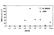
- the experimental results shown in FIG. 4 are experimental results for the accumulator 10 of this embodiment and the comparative example, and the liquid level position in the tank 11 when the compressor 1 is stopped by changing the refrigerant charging amount to the refrigeration cycle. And the vibration of the tank 11 at the time of starting the compressor 1 was measured. The operating conditions of the refrigeration cycle at this time are the same.
- shaft of FIG. 4 represents the vibration of the tank.
- the horizontal axis of FIG. 4 represents the liquid level position in the tank 11, and the liquid level position of L1 to Lmax becomes higher toward the right side of FIG. Lmax is the maximum liquid level position.
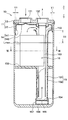
- the accumulator of the comparative example has a desiccant 16 arranged below the tank 11 as shown in FIG.
- liquid level position when the liquid level position is L3, all of the desiccant is immersed in the liquid phase refrigerant, and when the liquid level position is L4 to Lmax, a part of the desiccant is in the liquid phase. It was in a state of coming out of the refrigerant, and no vibration occurred at any liquid level position.
- the desiccant 16 is disposed at a position at least a predetermined distance from the inner wall of the tank 11. That is, the desiccant 16 is disposed at a position that avoids the dropping path of the liquid-phase refrigerant that falls from the outside of the outer edge of the umbrella-like member 14.
- the desiccant 16 is accommodated in the bag 161, and the bag 161 is fixed around the suction pipe 15 by the fixing portion 162.
- the present disclosure when the present disclosure is applied to the conventional accumulator in which the bag 161 containing the desiccant 16 is disposed below the tank 11 as in the comparative example described above, the location and fixing of the bag 161 are fixed. It is only necessary to change the method, and it is not necessary to change the design of the components of the accumulator.
- the container of the desiccant 16 is changed with respect to the first embodiment, and other configurations are the same as those in the first embodiment.
- the desiccant 16 is filled in a plastic container 163 and is fixed at a position below the suction port 153 in the outer pipe 152.
- the container 163 is disposed at a position at least a predetermined distance away from the inner wall of the tank 11 as in the first embodiment. In other words, the container 163 is disposed at a position that avoids the falling path of the liquid refrigerant that falls from the outer side of the outer edge of the umbrella-shaped member 14.
- the cross-sectional shape of the container 163 is a shape that occupies most of the cross-section of the tank 11 while avoiding the vicinity of the tank inner wall where the liquid-phase refrigerant falls.
- the desiccant container has flexibility
- the desiccant container is deformed by the weight of the desiccant, and the desiccant is biased.
- the container 163 of the present embodiment is made of plastic and is relatively hard, and thus can maintain a predetermined shape.
- the container 163 does not deform
- inclination of the desiccant 16 with which the inside of the container 163 was filled can be prevented.
- a container formed of a material other than plastic may be used as the container 163 as long as the predetermined shape can be maintained.
- the container 163 has a press-fit portion 164 having a shape along the outer peripheral surface of the suction pipe 15, and the suction pipe 15 is press-fitted and fixed to the press-fit portion 164.
- the press-fit portion 164 has a C shape corresponding to a range excluding a part of the suction pipe 15 in the circumferential direction.
- the suction pipe 15 is press-fitted into the press-fit part 164 by pressing the press-fit part 164 against the suction pipe 15 from the lateral direction.
- the plastic container 163 is press-fitted and fixed to the suction pipe 15, it is only necessary to newly prepare the container 163 having the shape described above.
- the components of the accumulator other than the container 163 The same conventional one can be used.
- the method of fixing the container 163 by press-fitting facilitates the step of assembling the desiccant 16 to the suction pipe 15 than the method of fixing the bag 161 by tying it.
- the press-fit portion 164 has a C shape, but may have an O shape.
- the container 163 is press-fitted and fixed to the suction pipe 15 by inserting the suction pipe 15 into the O-shaped press-fit portion 164.
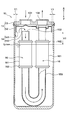
- the suction pipe is changed with respect to the first embodiment. That is, in this embodiment, as shown in FIG. 8, a U-shaped tube 159 is used as a suction pipe.
- the desiccant 16 is accommodated in a bag 161 as in the first embodiment, and this bag 161 is fixed by a fixing portion 162 in a state of being wound around a U-shaped tube 159.
- the present disclosure can be applied.
- a plastic container 163 may be used as in the second embodiment.
- the present disclosure is not limited to the above-described embodiment, and can be appropriately changed without departing from the gist of the present disclosure as illustrated below.
- the string-like fixing portion 162 is wound around the entire circumferential direction of the bag 161.
- 161 may be fixed.
- the ends of the bags 161 wound around the suction pipe 15 are sewn together with a fixing portion such as a thread, or the ring-shaped fixing portion is passed through an opening provided at the end of the bag 161, so that the bag 161 is It may be fixed to the suction pipe 15.
- the container 163 of the desiccant 16 is press-fitted and fixed to the suction pipe 15, but may be fixed by a fixing method other than press-fitting.
- the container 163 of the desiccant 16 and the outer pipe 152 of the suction pipe 15 may be integrally formed.
- the lid of the container 163 is a separate body.
- the umbrella-shaped member 14 has the shape shown in FIG. 2, but may be changed to another shape.
- the umbrella-shaped member 14 may be omitted.
- the desiccant 16 may be disposed avoiding the position directly below the refrigerant inlet 131.
- a part of the desiccant 16 is located above the maximum liquid level position Lmax when the compressor 1 is stopped. However, the desiccant 16 is entirely located. Also good.
Landscapes
- Engineering & Computer Science (AREA)
- Chemical & Material Sciences (AREA)
- Analytical Chemistry (AREA)
- Power Engineering (AREA)
- Physics & Mathematics (AREA)
- Mechanical Engineering (AREA)
- Thermal Sciences (AREA)
- General Engineering & Computer Science (AREA)
- General Chemical & Material Sciences (AREA)
- Oil, Petroleum & Natural Gas (AREA)
- Chemical Kinetics & Catalysis (AREA)
- Air-Conditioning For Vehicles (AREA)
Priority Applications (3)
| Application Number | Priority Date | Filing Date | Title |
|---|---|---|---|
| EP13835488.1A EP2896914B1 (en) | 2012-09-07 | 2013-08-02 | Accumulator |
| CN201380046352.4A CN104603555B (zh) | 2012-09-07 | 2013-08-02 | 储液器 |
| US14/425,292 US9636622B2 (en) | 2012-09-07 | 2013-08-02 | Accumulator |
Applications Claiming Priority (2)
| Application Number | Priority Date | Filing Date | Title |
|---|---|---|---|
| JP2012-197222 | 2012-09-07 | ||
| JP2012197222A JP5849909B2 (ja) | 2012-09-07 | 2012-09-07 | アキュムレータ |
Publications (1)
| Publication Number | Publication Date |
|---|---|
| WO2014038127A1 true WO2014038127A1 (ja) | 2014-03-13 |
Family
ID=50236765
Family Applications (1)
| Application Number | Title | Priority Date | Filing Date |
|---|---|---|---|
| PCT/JP2013/004700 Ceased WO2014038127A1 (ja) | 2012-09-07 | 2013-08-02 | アキュムレータ |
Country Status (5)
| Country | Link |
|---|---|
| US (1) | US9636622B2 (enExample) |
| EP (1) | EP2896914B1 (enExample) |
| JP (1) | JP5849909B2 (enExample) |
| CN (1) | CN104603555B (enExample) |
| WO (1) | WO2014038127A1 (enExample) |
Cited By (3)
| Publication number | Priority date | Publication date | Assignee | Title |
|---|---|---|---|---|
| US20170016657A1 (en) * | 2015-07-14 | 2017-01-19 | Fujikoki Corporation | Accumulator |
| US20170016658A1 (en) * | 2015-07-17 | 2017-01-19 | Fujikoki Corporation | Accumulator |
| CN107763908A (zh) * | 2016-08-17 | 2018-03-06 | 株式会社不二工机 | 储液器 |
Families Citing this family (20)
| Publication number | Priority date | Publication date | Assignee | Title |
|---|---|---|---|---|
| JP6155005B2 (ja) * | 2012-10-12 | 2017-06-28 | 株式会社不二工機 | アキュムレータ |
| JP6068909B2 (ja) * | 2012-10-02 | 2017-01-25 | 株式会社不二工機 | アキュムレータ |
| JP6068938B2 (ja) * | 2012-11-08 | 2017-01-25 | 株式会社不二工機 | アキュムレータ |
| JP6385222B2 (ja) * | 2014-09-22 | 2018-09-05 | 株式会社不二工機 | アキュムレータ |
| DE102015110574B4 (de) * | 2015-07-01 | 2018-12-13 | Halla Visteon Climate Control Corporation | Vorrichtung zum Abscheiden und Sammeln flüssigen Kältemittels eines Kältemittelkreislaufs |
| JP6661345B2 (ja) * | 2015-07-14 | 2020-03-11 | 株式会社不二工機 | アキュームレータ |
| JP6514981B2 (ja) * | 2015-07-17 | 2019-05-15 | 株式会社不二工機 | アキュームレータ |
| ES2612306B1 (es) * | 2015-11-12 | 2018-03-07 | Carlos BAÑO ANTON | Máquina productora de fluido en estado líquido |
| JP6747857B2 (ja) * | 2016-04-28 | 2020-08-26 | サンデン・オートモーティブクライメイトシステム株式会社 | アキュムレータ及びそれを備えた車両用空気調和装置 |
| JP6500839B2 (ja) * | 2016-05-19 | 2019-04-17 | 株式会社デンソー | アキュムレータおよび冷凍サイクル |
| JP6341958B2 (ja) * | 2016-08-17 | 2018-06-13 | 株式会社不二工機 | アキュームレータ |
| JP2018077016A (ja) * | 2016-11-10 | 2018-05-17 | サンデン・オートモーティブクライメイトシステム株式会社 | アキュムレータ |
| JP2018077015A (ja) * | 2016-11-10 | 2018-05-17 | サンデン・オートモーティブクライメイトシステム株式会社 | アキュムレータ |
| KR20180118397A (ko) * | 2017-04-21 | 2018-10-31 | 엘지전자 주식회사 | 어큐뮬레이터 |
| CN108759196A (zh) * | 2018-06-13 | 2018-11-06 | 苏州逸新和电子有限公司 | 一种过滤性能好的储液器 |
| CN112013581A (zh) * | 2019-05-30 | 2020-12-01 | 株式会社不二工机 | 储液器及其组装方法 |
| KR102750535B1 (ko) * | 2019-05-31 | 2025-01-06 | 현대자동차 주식회사 | 차량용 기액 분리장치 |
| JP7475061B2 (ja) | 2021-08-24 | 2024-04-26 | 株式会社不二工機 | アキュームレータ |
| JP7588440B2 (ja) | 2021-08-24 | 2024-11-22 | 株式会社不二工機 | アキュームレータ |
| WO2024158023A1 (ja) | 2023-01-26 | 2024-08-02 | 株式会社不二工機 | アキュームレータ |
Citations (4)
| Publication number | Priority date | Publication date | Assignee | Title |
|---|---|---|---|---|
| JPH11278045A (ja) * | 1997-09-24 | 1999-10-12 | Denso Corp | 冷凍サイクル装置 |
| JP2001082814A (ja) | 1999-09-09 | 2001-03-30 | Denso Corp | 冷凍サイクル装置およびそれに用いるアキュムレータ |
| JP2007232335A (ja) * | 2006-03-03 | 2007-09-13 | Denso Corp | 冷媒容器とその製造方法 |
| JP2009180469A (ja) | 2008-01-31 | 2009-08-13 | Calsonic Kansei Corp | 超臨界冷凍サイクル用アキュムレータ |
Family Cites Families (15)
| Publication number | Priority date | Publication date | Assignee | Title |
|---|---|---|---|---|
| US4331001A (en) * | 1981-05-11 | 1982-05-25 | General Motors Corporation | Accumulator-dehydrator assembly for an air conditioning system |
| US4509340A (en) * | 1983-11-10 | 1985-04-09 | Sealed Power Corporation | Accumulator-dehydrator assembly for an air conditioning system |
| US4768355A (en) | 1987-01-27 | 1988-09-06 | Ford Motor Company | Accumulator with refrigerant processing cartridge for automotive air conditioning system |
| JPH02290480A (ja) * | 1989-04-28 | 1990-11-30 | Nissan Motor Co Ltd | 車両用リキッドタンク |
| US5282370A (en) * | 1992-05-07 | 1994-02-01 | Fayette Tubular Technology Corporation | Air-conditioning system accumulator and method of making same |
| US5289697A (en) * | 1992-10-28 | 1994-03-01 | Eaton Corporation | Refrigerant receiver/drier |
| US5814136A (en) * | 1997-04-15 | 1998-09-29 | Stanhope Products Company | Desiccant container |
| EP0894651B1 (en) * | 1997-07-31 | 2003-09-10 | Denso Corporation | Refrigeration cycle apparatus |
| US6196019B1 (en) | 1997-12-16 | 2001-03-06 | Showa Aluminum Corporation | Accumulator |
| US6330810B1 (en) * | 2000-08-11 | 2001-12-18 | Showa Denko K.K. | Condensing apparatus for use in a refrigeration cycle receiver-dryer used for said condensing apparatus |
| US6389842B1 (en) | 2001-01-23 | 2002-05-21 | Delphi Technologies, Inc. | Accumulator-dehydrator assembly with anti-bump expansion chamber “J”-tube |
| US6481241B1 (en) * | 2001-08-29 | 2002-11-19 | Automotive Fluid Systems, Inc. | Accumulator desiccant bag and method of assembling |
| JP3870744B2 (ja) * | 2001-10-12 | 2007-01-24 | 株式会社デンソー | アキュムレータ |
| JP2008304097A (ja) | 2007-06-06 | 2008-12-18 | Calsonic Kansei Corp | アキュムレータ |
| JP5760993B2 (ja) | 2011-11-29 | 2015-08-12 | 株式会社デンソー | アキュムレータ |
-
2012
- 2012-09-07 JP JP2012197222A patent/JP5849909B2/ja active Active
-
2013
- 2013-08-02 US US14/425,292 patent/US9636622B2/en active Active
- 2013-08-02 CN CN201380046352.4A patent/CN104603555B/zh active Active
- 2013-08-02 WO PCT/JP2013/004700 patent/WO2014038127A1/ja not_active Ceased
- 2013-08-02 EP EP13835488.1A patent/EP2896914B1/en active Active
Patent Citations (4)
| Publication number | Priority date | Publication date | Assignee | Title |
|---|---|---|---|---|
| JPH11278045A (ja) * | 1997-09-24 | 1999-10-12 | Denso Corp | 冷凍サイクル装置 |
| JP2001082814A (ja) | 1999-09-09 | 2001-03-30 | Denso Corp | 冷凍サイクル装置およびそれに用いるアキュムレータ |
| JP2007232335A (ja) * | 2006-03-03 | 2007-09-13 | Denso Corp | 冷媒容器とその製造方法 |
| JP2009180469A (ja) | 2008-01-31 | 2009-08-13 | Calsonic Kansei Corp | 超臨界冷凍サイクル用アキュムレータ |
Cited By (6)
| Publication number | Priority date | Publication date | Assignee | Title |
|---|---|---|---|---|
| US20170016657A1 (en) * | 2015-07-14 | 2017-01-19 | Fujikoki Corporation | Accumulator |
| US10190809B2 (en) * | 2015-07-14 | 2019-01-29 | Fujikoki Corporation | Accumulator |
| US20170016658A1 (en) * | 2015-07-17 | 2017-01-19 | Fujikoki Corporation | Accumulator |
| US10215461B2 (en) * | 2015-07-17 | 2019-02-26 | Fujikoki Corporation | Accumulator |
| CN107763908A (zh) * | 2016-08-17 | 2018-03-06 | 株式会社不二工机 | 储液器 |
| CN107763908B (zh) * | 2016-08-17 | 2021-04-09 | 株式会社不二工机 | 储液器 |
Also Published As
| Publication number | Publication date |
|---|---|
| JP5849909B2 (ja) | 2016-02-03 |
| EP2896914A1 (en) | 2015-07-22 |
| US9636622B2 (en) | 2017-05-02 |
| EP2896914A4 (en) | 2016-07-06 |
| JP2014052139A (ja) | 2014-03-20 |
| CN104603555A (zh) | 2015-05-06 |
| CN104603555B (zh) | 2016-08-24 |
| EP2896914B1 (en) | 2021-04-21 |
| US20150231549A1 (en) | 2015-08-20 |
Similar Documents
| Publication | Publication Date | Title |
|---|---|---|
| JP5849909B2 (ja) | アキュムレータ | |
| US10215461B2 (en) | Accumulator | |
| US20170016657A1 (en) | Accumulator | |
| JP6500839B2 (ja) | アキュムレータおよび冷凍サイクル | |
| JP2015172469A (ja) | 気液分離器 | |
| JP2012102900A (ja) | コンデンサ | |
| JP2003090643A (ja) | 冷凍サイクル装置 | |
| JP6385222B2 (ja) | アキュムレータ | |
| US6389842B1 (en) | Accumulator-dehydrator assembly with anti-bump expansion chamber “J”-tube | |
| JP2000227265A (ja) | 受液器一体型冷媒凝縮器 | |
| JP6507057B2 (ja) | アキュームレータ | |
| US7249467B2 (en) | Gas-liquid separator for refrigerant cycle system | |
| CN107763907B (zh) | 储液器 | |
| JP2020094778A (ja) | アキュムレータ | |
| JP2019100624A (ja) | アキュームレータ | |
| JP2017198408A (ja) | アキュムレータ | |
| EP3293472B1 (en) | Accumulator | |
| WO2017146054A1 (ja) | アキュムレータ | |
| KR20120002107A (ko) | 자동차 공기조화장치용 리시버 드라이어 | |
| JP2007093121A (ja) | 冷凍サイクル用気液分離器 | |
| WO2018088127A1 (ja) | アキュムレータ | |
| JP2019086211A (ja) | 貯液器 | |
| WO2025263350A1 (ja) | 受液器 | |
| WO2023026885A1 (ja) | アキュームレータ | |
| WO2006067766A2 (en) | A cooling device |
Legal Events
| Date | Code | Title | Description |
|---|---|---|---|
| 121 | Ep: the epo has been informed by wipo that ep was designated in this application |
Ref document number: 13835488 Country of ref document: EP Kind code of ref document: A1 |
|
| WWE | Wipo information: entry into national phase |
Ref document number: 2013835488 Country of ref document: EP |
|
| WWE | Wipo information: entry into national phase |
Ref document number: 14425292 Country of ref document: US |
|
| NENP | Non-entry into the national phase |
Ref country code: DE |