WO2014034079A1 - 電源装置及び電源装置を備える車両並びに蓄電装置 - Google Patents
電源装置及び電源装置を備える車両並びに蓄電装置 Download PDFInfo
- Publication number
- WO2014034079A1 WO2014034079A1 PCT/JP2013/005015 JP2013005015W WO2014034079A1 WO 2014034079 A1 WO2014034079 A1 WO 2014034079A1 JP 2013005015 W JP2013005015 W JP 2013005015W WO 2014034079 A1 WO2014034079 A1 WO 2014034079A1
- Authority
- WO
- WIPO (PCT)
- Prior art keywords
- power supply
- holder
- supply device
- bus bar
- battery
- Prior art date
- Legal status (The legal status is an assumption and is not a legal conclusion. Google has not performed a legal analysis and makes no representation as to the accuracy of the status listed.)
- Ceased
Links
Images









Classifications
-
- H—ELECTRICITY
- H01—ELECTRIC ELEMENTS
- H01M—PROCESSES OR MEANS, e.g. BATTERIES, FOR THE DIRECT CONVERSION OF CHEMICAL ENERGY INTO ELECTRICAL ENERGY
- H01M10/00—Secondary cells; Manufacture thereof
- H01M10/04—Construction or manufacture in general
- H01M10/0481—Compression means other than compression means for stacks of electrodes and separators
-
- B—PERFORMING OPERATIONS; TRANSPORTING
- B60—VEHICLES IN GENERAL
- B60L—PROPULSION OF ELECTRICALLY-PROPELLED VEHICLES; SUPPLYING ELECTRIC POWER FOR AUXILIARY EQUIPMENT OF ELECTRICALLY-PROPELLED VEHICLES; ELECTRODYNAMIC BRAKE SYSTEMS FOR VEHICLES IN GENERAL; MAGNETIC SUSPENSION OR LEVITATION FOR VEHICLES; MONITORING OPERATING VARIABLES OF ELECTRICALLY-PROPELLED VEHICLES; ELECTRIC SAFETY DEVICES FOR ELECTRICALLY-PROPELLED VEHICLES
- B60L3/00—Electric devices on electrically-propelled vehicles for safety purposes; Monitoring operating variables, e.g. speed, deceleration or energy consumption
- B60L3/0023—Detecting, eliminating, remedying or compensating for drive train abnormalities, e.g. failures within the drive train
- B60L3/0046—Detecting, eliminating, remedying or compensating for drive train abnormalities, e.g. failures within the drive train relating to electric energy storage systems, e.g. batteries or capacitors
-
- B—PERFORMING OPERATIONS; TRANSPORTING
- B60—VEHICLES IN GENERAL
- B60L—PROPULSION OF ELECTRICALLY-PROPELLED VEHICLES; SUPPLYING ELECTRIC POWER FOR AUXILIARY EQUIPMENT OF ELECTRICALLY-PROPELLED VEHICLES; ELECTRODYNAMIC BRAKE SYSTEMS FOR VEHICLES IN GENERAL; MAGNETIC SUSPENSION OR LEVITATION FOR VEHICLES; MONITORING OPERATING VARIABLES OF ELECTRICALLY-PROPELLED VEHICLES; ELECTRIC SAFETY DEVICES FOR ELECTRICALLY-PROPELLED VEHICLES
- B60L50/00—Electric propulsion with power supplied within the vehicle
- B60L50/50—Electric propulsion with power supplied within the vehicle using propulsion power supplied by batteries or fuel cells
- B60L50/60—Electric propulsion with power supplied within the vehicle using propulsion power supplied by batteries or fuel cells using power supplied by batteries
- B60L50/64—Constructional details of batteries specially adapted for electric vehicles
-
- H—ELECTRICITY
- H01—ELECTRIC ELEMENTS
- H01M—PROCESSES OR MEANS, e.g. BATTERIES, FOR THE DIRECT CONVERSION OF CHEMICAL ENERGY INTO ELECTRICAL ENERGY
- H01M50/00—Constructional details or processes of manufacture of the non-active parts of electrochemical cells other than fuel cells, e.g. hybrid cells
- H01M50/20—Mountings; Secondary casings or frames; Racks, modules or packs; Suspension devices; Shock absorbers; Transport or carrying devices; Holders
- H01M50/204—Racks, modules or packs for multiple batteries or multiple cells
- H01M50/207—Racks, modules or packs for multiple batteries or multiple cells characterised by their shape
- H01M50/209—Racks, modules or packs for multiple batteries or multiple cells characterised by their shape adapted for prismatic or rectangular cells
-
- H—ELECTRICITY
- H01—ELECTRIC ELEMENTS
- H01M—PROCESSES OR MEANS, e.g. BATTERIES, FOR THE DIRECT CONVERSION OF CHEMICAL ENERGY INTO ELECTRICAL ENERGY
- H01M50/00—Constructional details or processes of manufacture of the non-active parts of electrochemical cells other than fuel cells, e.g. hybrid cells
- H01M50/20—Mountings; Secondary casings or frames; Racks, modules or packs; Suspension devices; Shock absorbers; Transport or carrying devices; Holders
- H01M50/249—Mountings; Secondary casings or frames; Racks, modules or packs; Suspension devices; Shock absorbers; Transport or carrying devices; Holders specially adapted for aircraft or vehicles, e.g. cars or trains
-
- H—ELECTRICITY
- H01—ELECTRIC ELEMENTS
- H01M—PROCESSES OR MEANS, e.g. BATTERIES, FOR THE DIRECT CONVERSION OF CHEMICAL ENERGY INTO ELECTRICAL ENERGY
- H01M50/00—Constructional details or processes of manufacture of the non-active parts of electrochemical cells other than fuel cells, e.g. hybrid cells
- H01M50/20—Mountings; Secondary casings or frames; Racks, modules or packs; Suspension devices; Shock absorbers; Transport or carrying devices; Holders
- H01M50/262—Mountings; Secondary casings or frames; Racks, modules or packs; Suspension devices; Shock absorbers; Transport or carrying devices; Holders with fastening means, e.g. locks
- H01M50/264—Mountings; Secondary casings or frames; Racks, modules or packs; Suspension devices; Shock absorbers; Transport or carrying devices; Holders with fastening means, e.g. locks for cells or batteries, e.g. straps, tie rods or peripheral frames
-
- H—ELECTRICITY
- H01—ELECTRIC ELEMENTS
- H01M—PROCESSES OR MEANS, e.g. BATTERIES, FOR THE DIRECT CONVERSION OF CHEMICAL ENERGY INTO ELECTRICAL ENERGY
- H01M50/00—Constructional details or processes of manufacture of the non-active parts of electrochemical cells other than fuel cells, e.g. hybrid cells
- H01M50/20—Mountings; Secondary casings or frames; Racks, modules or packs; Suspension devices; Shock absorbers; Transport or carrying devices; Holders
- H01M50/289—Mountings; Secondary casings or frames; Racks, modules or packs; Suspension devices; Shock absorbers; Transport or carrying devices; Holders characterised by spacing elements or positioning means within frames, racks or packs
- H01M50/291—Mountings; Secondary casings or frames; Racks, modules or packs; Suspension devices; Shock absorbers; Transport or carrying devices; Holders characterised by spacing elements or positioning means within frames, racks or packs characterised by their shape
-
- H—ELECTRICITY
- H01—ELECTRIC ELEMENTS
- H01M—PROCESSES OR MEANS, e.g. BATTERIES, FOR THE DIRECT CONVERSION OF CHEMICAL ENERGY INTO ELECTRICAL ENERGY
- H01M50/00—Constructional details or processes of manufacture of the non-active parts of electrochemical cells other than fuel cells, e.g. hybrid cells
- H01M50/50—Current conducting connections for cells or batteries
- H01M50/502—Interconnectors for connecting terminals of adjacent batteries; Interconnectors for connecting cells outside a battery casing
- H01M50/507—Interconnectors for connecting terminals of adjacent batteries; Interconnectors for connecting cells outside a battery casing comprising an arrangement of two or more busbars within a container structure, e.g. busbar modules
-
- H—ELECTRICITY
- H01—ELECTRIC ELEMENTS
- H01M—PROCESSES OR MEANS, e.g. BATTERIES, FOR THE DIRECT CONVERSION OF CHEMICAL ENERGY INTO ELECTRICAL ENERGY
- H01M50/00—Constructional details or processes of manufacture of the non-active parts of electrochemical cells other than fuel cells, e.g. hybrid cells
- H01M50/50—Current conducting connections for cells or batteries
- H01M50/502—Interconnectors for connecting terminals of adjacent batteries; Interconnectors for connecting cells outside a battery casing
- H01M50/519—Interconnectors for connecting terminals of adjacent batteries; Interconnectors for connecting cells outside a battery casing comprising printed circuit boards [PCB]
-
- H—ELECTRICITY
- H02—GENERATION; CONVERSION OR DISTRIBUTION OF ELECTRIC POWER
- H02J—ELECTRIC POWER NETWORKS; CIRCUIT ARRANGEMENTS OR SYSTEMS FOR SUPPLYING OR DISTRIBUTING ELECTRIC POWER; SYSTEMS FOR STORING ELECTRIC ENERGY
- H02J7/00—Circuit arrangements for charging or discharging batteries or for supplying loads from batteries
- H02J7/50—Circuit arrangements for charging or discharging batteries or for supplying loads from batteries acting upon multiple batteries simultaneously or sequentially
-
- H—ELECTRICITY
- H01—ELECTRIC ELEMENTS
- H01M—PROCESSES OR MEANS, e.g. BATTERIES, FOR THE DIRECT CONVERSION OF CHEMICAL ENERGY INTO ELECTRICAL ENERGY
- H01M2220/00—Batteries for particular applications
- H01M2220/20—Batteries in motive systems, e.g. vehicle, ship, plane
-
- H—ELECTRICITY
- H02—GENERATION; CONVERSION OR DISTRIBUTION OF ELECTRIC POWER
- H02J—ELECTRIC POWER NETWORKS; CIRCUIT ARRANGEMENTS OR SYSTEMS FOR SUPPLYING OR DISTRIBUTING ELECTRIC POWER; SYSTEMS FOR STORING ELECTRIC ENERGY
- H02J2105/00—Networks for supplying or distributing electric power characterised by their spatial reach or by the load
- H02J2105/30—Networks for supplying or distributing electric power characterised by their spatial reach or by the load the load networks being external to vehicles, i.e. exchanging power with vehicles
- H02J2105/33—Networks for supplying or distributing electric power characterised by their spatial reach or by the load the load networks being external to vehicles, i.e. exchanging power with vehicles exchanging power with road vehicles
- H02J2105/37—Networks for supplying or distributing electric power characterised by their spatial reach or by the load the load networks being external to vehicles, i.e. exchanging power with vehicles exchanging power with road vehicles exchanging power with electric vehicles [EV] or with hybrid electric vehicles [HEV]
-
- H—ELECTRICITY
- H02—GENERATION; CONVERSION OR DISTRIBUTION OF ELECTRIC POWER
- H02J—ELECTRIC POWER NETWORKS; CIRCUIT ARRANGEMENTS OR SYSTEMS FOR SUPPLYING OR DISTRIBUTING ELECTRIC POWER; SYSTEMS FOR STORING ELECTRIC ENERGY
- H02J7/00—Circuit arrangements for charging or discharging batteries or for supplying loads from batteries
- H02J7/14—Circuit arrangements for charging or discharging batteries or for supplying loads from batteries for charging batteries from dynamo-electric generators driven at varying speed, e.g. on vehicle
- H02J7/1415—Circuit arrangements for charging or discharging batteries or for supplying loads from batteries for charging batteries from dynamo-electric generators driven at varying speed, e.g. on vehicle with a generator driven by a prime mover other than the motor of a vehicle
-
- H—ELECTRICITY
- H02—GENERATION; CONVERSION OR DISTRIBUTION OF ELECTRIC POWER
- H02J—ELECTRIC POWER NETWORKS; CIRCUIT ARRANGEMENTS OR SYSTEMS FOR SUPPLYING OR DISTRIBUTING ELECTRIC POWER; SYSTEMS FOR STORING ELECTRIC ENERGY
- H02J7/00—Circuit arrangements for charging or discharging batteries or for supplying loads from batteries
- H02J7/34—Parallel operation in networks using both storage and other DC sources, e.g. providing buffering
- H02J7/35—Parallel operation in networks using both storage and other DC sources, e.g. providing buffering with light sensitive cells
-
- Y—GENERAL TAGGING OF NEW TECHNOLOGICAL DEVELOPMENTS; GENERAL TAGGING OF CROSS-SECTIONAL TECHNOLOGIES SPANNING OVER SEVERAL SECTIONS OF THE IPC; TECHNICAL SUBJECTS COVERED BY FORMER USPC CROSS-REFERENCE ART COLLECTIONS [XRACs] AND DIGESTS
- Y02—TECHNOLOGIES OR APPLICATIONS FOR MITIGATION OR ADAPTATION AGAINST CLIMATE CHANGE
- Y02E—REDUCTION OF GREENHOUSE GAS [GHG] EMISSIONS, RELATED TO ENERGY GENERATION, TRANSMISSION OR DISTRIBUTION
- Y02E60/00—Enabling technologies; Technologies with a potential or indirect contribution to GHG emissions mitigation
- Y02E60/10—Energy storage using batteries
-
- Y—GENERAL TAGGING OF NEW TECHNOLOGICAL DEVELOPMENTS; GENERAL TAGGING OF CROSS-SECTIONAL TECHNOLOGIES SPANNING OVER SEVERAL SECTIONS OF THE IPC; TECHNICAL SUBJECTS COVERED BY FORMER USPC CROSS-REFERENCE ART COLLECTIONS [XRACs] AND DIGESTS
- Y02—TECHNOLOGIES OR APPLICATIONS FOR MITIGATION OR ADAPTATION AGAINST CLIMATE CHANGE
- Y02P—CLIMATE CHANGE MITIGATION TECHNOLOGIES IN THE PRODUCTION OR PROCESSING OF GOODS
- Y02P70/00—Climate change mitigation technologies in the production process for final industrial or consumer products
- Y02P70/50—Manufacturing or production processes characterised by the final manufactured product
-
- Y—GENERAL TAGGING OF NEW TECHNOLOGICAL DEVELOPMENTS; GENERAL TAGGING OF CROSS-SECTIONAL TECHNOLOGIES SPANNING OVER SEVERAL SECTIONS OF THE IPC; TECHNICAL SUBJECTS COVERED BY FORMER USPC CROSS-REFERENCE ART COLLECTIONS [XRACs] AND DIGESTS
- Y02—TECHNOLOGIES OR APPLICATIONS FOR MITIGATION OR ADAPTATION AGAINST CLIMATE CHANGE
- Y02T—CLIMATE CHANGE MITIGATION TECHNOLOGIES RELATED TO TRANSPORTATION
- Y02T10/00—Road transport of goods or passengers
- Y02T10/60—Other road transportation technologies with climate change mitigation effect
- Y02T10/70—Energy storage systems for electromobility, e.g. batteries
-
- Y—GENERAL TAGGING OF NEW TECHNOLOGICAL DEVELOPMENTS; GENERAL TAGGING OF CROSS-SECTIONAL TECHNOLOGIES SPANNING OVER SEVERAL SECTIONS OF THE IPC; TECHNICAL SUBJECTS COVERED BY FORMER USPC CROSS-REFERENCE ART COLLECTIONS [XRACs] AND DIGESTS
- Y10—TECHNICAL SUBJECTS COVERED BY FORMER USPC
- Y10T—TECHNICAL SUBJECTS COVERED BY FORMER US CLASSIFICATION
- Y10T29/00—Metal working
- Y10T29/49—Method of mechanical manufacture
- Y10T29/49002—Electrical device making
- Y10T29/49108—Electric battery cell making
Definitions
- the present invention relates to a power supply device in which a plurality of battery cells are stacked, a vehicle including the power supply device, and a power storage device, and more particularly, to a motor mounted on an electric vehicle such as a hybrid vehicle, a fuel cell vehicle, an electric vehicle, and an electric motorcycle.
- the present invention relates to a power supply device, a power supply device that supplies power to a power source for large current used for household or factory power storage applications, a vehicle including the power supply device, and a power storage device.
- the power supply device for the vehicle increases the output voltage by connecting a large number of rechargeable secondary battery cells in series.
- An example of a conventional power supply device is shown in an exploded perspective view of FIG.
- a plurality of rectangular battery cells 221 are stacked, and an end plate 223 is disposed on the end surface of the stacked body. Further, the end plates 223 are fastened with a bind bar 224.
- the bind bar 224 is formed by bending a metal plate. Further, an insulating bus bar holder is fixed on the upper surface of the laminate.
- the insulating bus bar holder is interposed between the upper surface of the stack of battery cells 221 and the metal binding bar 224, and insulates the outer cans of the battery cells 221 that are fastened by the bind bar 224 from each other. .
- a circuit board or the like is fixed to the upper surface of the bus bar holder. On the circuit board, a cell voltage detection circuit for each battery cell, a circuit for performing various controls, and the like are mounted. For this reason, at the time of assembling the power supply device, the bus bar holder is first fixed in a state where the battery cells 221 are stacked, and then fastened by the bind bar 224.
- a main object of the present invention is to provide a power supply device that can efficiently perform assembly work, a vehicle including the power supply device, and a power storage device.
- a plurality of battery cells each having a square shape and electrode terminals and a battery stack in which the battery cells are stacked are fastened.
- the intermediate holder and the side holders positioned on the side surfaces on both sides of the intermediate holder are divided, and the side holder and the intermediate holder are fitted to each other. It can be provided with.
- the bus bar holder has a split structure, so that the intermediate holder can be fixed in a state where the battery stack is fastened by the fastening means including the side holders first, so that the pressing of the battery stack by the jig can be quickly performed. The assembly workability is improved.
- claw part which made the said fitting structure protrude from one surface in the interface which joins the said intermediate holder and a side surface holder, and the other surface It can comprise with the latching piece which receives this nail
- the bus bar holder is extended in the stacking direction of the battery cells, and the bus bar holder is connected to the intermediate holder and the side holder in the extension direction.
- the fastening means is disposed on the side surface of the battery stack, and is spaced apart in the vertical direction. Can be configured.
- the power supply device can further include an insulating sheet that is interposed between the fastening means and the battery stack. Even if it uses electroconductive members, such as a metal plate, for the fastening means, the situation which makes the exterior cans of battery cells connect can be avoided, and safety can be improved.
- the side holder is provided with a U-shaped slit having a U-shaped cross-sectional view having an open side so that an edge of the upper surface covering portion can be inserted. Can be formed.
- the fastening means is provided with an intermediate fixing protrusion that protrudes toward the intermediate holder at the intermediate portion, and the intermediate holder includes the intermediate fixing protrusion.
- An intermediate holding portion for holding the intermediate fixing protrusion can be provided at a position corresponding to the fixing protrusion.
- the intermediate fixing protrusion extends a part of the fastening means across the side holder and protrudes toward the intermediate holder. It is a bent piece that is bent, and the intermediate holding portion can be a slit into which the bent piece is inserted.
- the side holder can be formed with a recess for holding the bent piece. According to the above configuration, the bent piece can be held and held in the concave portion.
- one or more bind holes can be opened in the fastening means.
- the bus bar holder has an opening for positioning guides for arranging the bus bars, and a grid-like insulating portion is provided in each positioning guide. Can do.
- the battery stack further includes an insulating spacer interposed between the battery cells, and the spacer is a spacer at the center.
- a hole can be provided. Even if the center part of a battery cell expand
- the spacer can have the spacer hole portion as a through hole.
- the spacer hole can be easily formed in the spacer.
- the power supply device further includes a circuit board mounted with an electronic circuit for monitoring the battery cell, which is fixed to the upper surface of the bus bar holder, A substrate positioning boss for fixing to the circuit board is provided at the center, and the substrate positioning boss can form a holding projection for holding the circuit board around the board positioning boss.
- the circuit board can be positioned and fixed on the upper surface of the bus bar.
- the power supply device further includes a holder cover that covers the upper surface of the circuit board, and the board cover is screwed onto the board positioning boss with the bus bar holder. Screw holes can be opened.
- a traveling motor that is supplied with power from the power supply device, a vehicle main body including the power supply device and the motor, And a wheel driven by a motor to cause the vehicle body to travel.
- the power supply device includes a power supply controller that controls charging / discharging of the power supply device, and the power supply controller enables charging of the power supply device with external power, and It can be controlled to charge the power supply device.
- each of the battery cells each having a square shape and having an electrode terminal, fastening means for fastening the battery stack in which the battery cells are stacked, and the electrode terminals of the battery cells
- the present invention relates to a method of manufacturing a power supply device including a bus bar for connecting a battery and an insulating bus bar holder that covers an upper surface of the battery stack.
- This manufacturing method is a manufacturing method of a power supply device in which the bus bar holder is divided into an intermediate intermediate holder and side holders on both side surfaces, and the side holders are respectively provided at corners on the upper surface of the battery stack.
- FIG. 5 is a cross-sectional perspective view taken along line VV in FIG. 1. It is a principal part enlarged view of FIG.
- FIG. 6 is a schematic cross-sectional view showing a fitting structure according to Embodiment 2.
- FIG. 2 is a cross-sectional perspective view taken along line XX in FIG. 1. It is a principal part enlarged view of FIG.
- FIG. 3 is an enlarged exploded perspective view showing a portion surrounded by a broken line in the intermediate fixing structure of FIG. 2. It is a disassembled perspective view which shows the structure which latches a fastening means to an end plate. It is a disassembled perspective view which shows the structure which latches the fastening means which concerns on Embodiment 3 to an end plate. It is a disassembled perspective view which shows the structure which latches the fastening means which concerns on Embodiment 4 to an end plate. It is a front view which shows the structure which latches the fastening means shown to FIG. 13A to an end plate. It is a vertical sectional view showing the state where the end plate shown in FIG. 13D is fixed to the base plate.
- the embodiment described below exemplifies a power supply device, an electric vehicle including the power supply device, a power storage device, and a method of manufacturing the power supply device for embodying the technical idea of the present invention.
- the manufacturing method of the power supply device, the electric vehicle including the power supply device, the power storage device, and the power supply device is not specified as follows.
- the dimensions, materials, shapes, relative arrangements, and the like of the constituent members described in the embodiments are not intended to limit the scope of the present invention only to the description unless otherwise specified. It's just an example. Note that the size, positional relationship, and the like of the members shown in each drawing may be exaggerated for clarity of explanation.
- each element constituting the present invention may be configured such that a plurality of elements are constituted by the same member and the plurality of elements are shared by one member, and conversely, the function of one member is constituted by a plurality of members. It can also be realized by sharing.
- the contents described in some examples and embodiments may be used in other examples and embodiments.
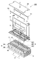
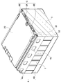
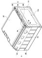
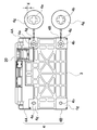
- FIG. 1 is a perspective view showing the power supply device 100 according to Embodiment 1
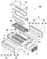
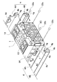
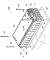
- FIG. 2 is an exploded perspective view of the power supply device 100 of FIG. 1
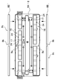
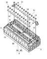
- FIG. 3 is a further exploded perspective view of the power supply device 100 of FIG. 5 is a cross-sectional perspective view and a main part enlarged view taken along line VV of FIG. 1
- FIG. 6 is a main part enlarged view of FIG. 5
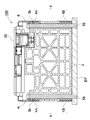
- FIG. 9 is a cross-sectional view of the power supply device 100, FIG.
- FIG. 10 is a cross-sectional perspective view along line XX in FIG. 10 is an enlarged exploded perspective view showing a portion surrounded by a broken line of the intermediate fixing structure in FIG. 2, and
- FIG. 13A is an exploded perspective view showing a structure for locking the fastening means 4 to the end plate 3.
- FIG. 13B is an exploded perspective view showing a structure for locking the fastening means according to Embodiment 3 to the end plate, and FIG. 13C.
- FIG. 13D is a front view showing a structure for locking the fastening means shown in FIG. 13A to the end plate, and
- FIG. 14 is a circuit board 9.
- FIG. 15 is a schematic cross-sectional view showing a fixing portion of the circuit board 9, respectively.
- the power supply device 100 shown in these drawings includes a plurality of battery cells 1, spacers 15 interposed between the battery cells 1, and battery stacks 2 in which the battery cells 1 and the spacers 15 are alternately stacked.
- An end plate 3 disposed on each end surface, a fastening means 4 for fastening the end plates 3 to each other, a bus bar holder 8 fixed to the upper surface of the battery stack 2, and a bus bar for connecting the electrode terminals 13 of the battery cells 1 to each other. 14.
- the end plate 3 is fastened in a state where the battery stack 2 is stacked, the end plate 3 is made of a highly rigid member made of metal or the like. Furthermore, the fastening means 4 is similarly composed of a highly rigid metal plate or the like. Here, the metal plate is bent in a U shape in a sectional view, and the end portion is fixed to the end plate 3 by screwing or the like.
- the fastening means 4 fastens the side surface of the battery stack 2. Furthermore, the fastening means 4 also serves as a configuration for pressing the upper surface of the battery stack 2. That is, the battery stack 2 is fastened in a stacked state and pressed from the upper surface, so that the upper surface of the battery stack 2, that is, the upper surface of each battery cell 1 can be made substantially flush. (Bus bar holder 8)
- the bus bar holder 8 covers the upper surface of the battery stack 2.
- the bus bar holder 8 holds the bus bar 14 that connects the electrode terminals 13 of the battery cell 1 and insulates the bus bar 14 to prevent unnecessary conduction between the bus bar 14 and the battery cell 1.
- the bus bar holder 8 is formed of an insulating member. In this example, it is made of resin such as PPE. (Intermediate holder 8A, side holder 8B)
- the bus bar holder 8 is extended in the stacking direction of the battery cells 1. As shown in the exploded perspective view of FIG. 3 and the plan view of FIG. 4, the bus bar holder 8 includes an intermediate holder 8A positioned in the middle and side surfaces positioned on the side surfaces of the intermediate holder 8A in the direction intersecting the extension direction. The holder 8B is divided. In this way, the bus bar holder 8 is divided into three parts, so that the intermediate holder 8A is press-fitted between the side holders 8B with the side holders 8B fixed to the top corners of the battery stack 2 first. As a result, it is possible to connect and fix the power supply device and to improve the workability of the power supply device assembly. (Fitting structure 30)
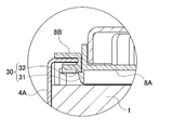
- the side holder 8B and the intermediate holder 8A are provided with a fitting structure 30 for fitting each other at an interface where they are joined.
- the claw portion 31 protruding in the shape of a claw on the wall surface of the intermediate holder 8A is provided on the side holder 8B at a position corresponding to the claw portion 31.
- the latching piece 32 for receiving is provided, and the intermediate holder 8A and the side holder 8B can be fixed by fitting them.
- the intermediate holder 8 ⁇ / b> A has claw portions 31 on both side surfaces.
- claw part 31 is spaced apart and provided in several places in each side surface.
- each claw portion 31 is provided with an inclined surface so that the lower part is narrow and the upper part is wide in the sectional view of the intermediate holder 8 ⁇ / b> A.
- the locking piece 32 of the side surface holder 8B is locked here. With this structure, a detent structure for preventing the intermediate holder 8A once fitted from being detached from the side holder 8B is realized.
- the intermediate holder 8A when the intermediate holder 8A is pushed in and fitted between the side holders 8B, the stepped portion is locked by the locking piece 32 thereafter, and the upward movement of the intermediate holder 8A is prevented, and the intermediate holder 8A can be stably fixed to the side holder 8B.
- claw part 31 can also be provided continuously along the longitudinal direction of an intermediate holder not only in the structure which provides several separately. (Embodiment 2)
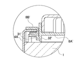
- fitting structure is not limited to this configuration, and other configurations capable of fitting the intermediate holder and the side holder can be appropriately employed.
- a claw portion 31 ′ may be provided on the side holder 8B ′ side
- a locking piece 32 ′ may be provided on the intermediate holder 8A ′ side.
- the fastening means 4 is extended in the stacking direction of the battery stack 2, and both ends are fixed to the end plate 3 to fasten the battery stack 2 in the stacking direction.
- the fastening means 4 shown in these drawings are respectively disposed on the side surfaces 2B on both sides different from the first surface 2A that hits the upper surface of the battery stack 2.
- the fastening means 4 is a metal plate having a predetermined width and a predetermined thickness along the surface of the battery stack 2.
- the fastening means 4 can be a metal plate such as iron, preferably a steel plate.
- the fastening means 4 made of a metal plate is provided with connecting portions 4b connected to the end plate 3 at both ends of the side surface covering portion 4a.
- the fastening means 4 in the figure is bent at substantially right angles at both ends along the main surface of the end plate 3 to provide a connecting portion 4b.
- the connecting portions 4 b at both ends are connected to the end plate 3, whereby the connecting portions 4 b of the fastening means 4 are locked to the pair of end plates 3 disposed at both ends of the battery stack 2.
- the battery laminate 2 is sandwiched from both ends so that the end plates 3 are spaced at a predetermined interval.
- the fastening means 4 of FIGS. 2 and 3 connects the connecting portion 4 b to the fitting recesses 3 A provided at the four corners of the end plate 3, and connects the pair of end plates 3 by the four fastening means 4. . Therefore, the connecting portion 4 b of the fastening means 4 is bent so as to follow the fitting recess 3 ⁇ / b> A of the end plate 3. (First bind bar 4A, second bind bar 4B)
- the fastening means 4 is provided on each side surface of the battery stack 2 so as to be spaced apart in the vertical direction.
- the fastening means 4 includes a first bind bar 4A and a second bind bar 4B.
- the first band bar is disposed at a corner on the upper surface side of the battery stack 2.
- the first bind bar 4A includes a side surface portion that contacts the side surface of the battery stack 2 and a side surface portion so that the folded curved surface has an L shape in cross section in both the horizontal direction and the vertical direction.
- the first bind bar 4 ⁇ / b> A has an upper surface covering portion that is L-shaped in a vertical sectional view so as to be suppressed from above the battery stack 2. 4c is formed.
- the side surface holder 8B is interposed. That is, the side holder 8B is first fixed to the corner of the battery stack 2, and then the side holder 8B is pressed with the first bind bar 4A. (Insulation sheet 54)
- the first bind bar 4A is bent in an L shape in a vertical sectional view from the side surface to the top surface of the battery stack 2, so that adjacent battery cells are also formed on the side surface of the battery stack 2. It is necessary to insulate one another. For this reason, the insulating sheet 54 is interposed between the side surface of the battery stack 2 and the first bind bar 4A.
- a resin sheet having excellent insulating properties such as PET, can be used.
- the insulating sheet 54 and the side holder 8B are separate members, but they can be integrated into one member. (U-shaped slit 8c)
- the upper surface covering portion 4c of the first bind bar 4A can be covered without exposing the upper surface of the first bind bar 4A in a state where the upper surface of the battery cell 1 is pressed. As a result, unintended conduction can be further avoided.
- the upper surface of the first bind bar 4 ⁇ / b> A is covered with the side holder 8 ⁇ / b> B.
- the side holder 8B has a U-shaped slit opened on the side surface so as to have a U-shape in a vertical sectional view, and the tip of the upper surface covering portion 4c of the first bind bar 4A is formed in the U-shaped slit 8c. Is inserted.
- the first bind bar 4A is provided with an intermediate fixing mechanism for coupling with the bus bar holder 8 at the intermediate portion thereof.
- the first bind bar 4A is provided with an intermediate fixing protrusion 4e that protrudes toward the intermediate holder 8A in the middle thereof.
- the intermediate holder 8A is provided with an intermediate holding portion for holding the intermediate fixing protrusion 4e at a position corresponding to the intermediate fixing protrusion 4e.
- the fastening means As the number of battery cells constituting the battery stack increases, the fastening means becomes longer, and accordingly, a space is easily generated between the intermediate portion of the fastening means and the battery stack.
- the fastening means basically generates a stress that fastens the end plates, and is effective for fastening the battery stack, but the stress that presses the upper surface and side surfaces thereof is weakened.
- the longer the fastening means is in the battery cell stacking direction the easier it is to separate from the battery stack at the intermediate portion. Therefore, as described above, the upper surface of the battery stack 2 can be prevented from rising of the first bind bar 4A by being inserted into the U-shaped slit 8c.
- the side surface of the battery stack 2 is prevented from being lifted from the side surface by being coupled to the bus bar holder 8 by an intermediate fixing mechanism. (Intermediate fixing protrusion 4e)
- the intermediate fixing protrusion 4e extends from the upper surface covering portion 4c on the upper surface of the first bind bar 4A to the intermediate holder 8A side. In particular, it has a bent piece 4f whose upper end edge is bent upward and protruded toward the intermediate holder 8A.
- the intermediate fixing protrusion 4e is preferably provided integrally with the fastening means 4 so that the configuration can be simplified. (Recess 8b)
- the side holder 8B is provided with a portion corresponding to the intermediate fixing projection 4e in the middle portion of the U-shaped slit 8c so that the intermediate fixing projection 4e can be extended to the side of the intermediate holder 8A beyond the side holder 8B.
- the bottom surface of the letter-shaped slit 8c is penetrated.
- the side surface holder 8B cuts out one side of the U-shaped slit 8c to form a recess 8b.
- the concave portion 8b is formed to be approximately equal to the width of the intermediate fixing protrusion 4e, whereby the intermediate fixing protrusion 4e can be positioned and held by the concave portion 8b. (Intermediate holding part)
- the intermediate holding portion of the intermediate holder 8A is a locking slit 8a for inserting the bent piece 4f.
- the bent piece 4f is inserted at a position corresponding to the bent piece 4f of the intermediate fixing protrusion 4e in the middle in the longitudinal direction of the intermediate holder 8A.
- a locking slit 8a having a size that can be locked is opened.
- the bent piece 4f is bent substantially perpendicularly to the intermediate fixing protrusion 4e.
- the bent piece 4f, the intermediate fixing protrusion 4e, and the side surface covering portion 4a are bent in a stepped shape.
- the intermediate fixing mechanism is provided only at the center in the longitudinal direction. However, it goes without saying that the intermediate fixing mechanism can be provided at a plurality of locations in the longitudinal direction. . (Binding hole 4d)
- the first bind bar 4A opens one or more bind holes 4d. By forming such an opening, the first bind bar 4A can be easily deformed. In particular, even when the battery cell 1 expands due to charging / discharging and the like, and the length in the stacking direction of the battery stack 2 is increased, an excessive load is applied to the attachment portion of the fastening means 4 and the end plate 3. Can be reduced by deformation of the part. In addition, since the mechanical strength of the fastening means 4 becomes weaker as the number of binding holes increases or increases, the number and size of the binding holes are set in consideration of the balance between strength and ease of deformation. (Second bind bar 4B)
- the second bind bar 4B is disposed at the corner on the lower surface side of the battery stack 2.
- the second bind bar 4B includes a side surface portion that contacts the side surface of the battery stack 2 and a side surface portion that is perpendicular to the side surface portion so that the folded curved surface has an L shape in cross section in both the horizontal direction and the vertical direction. A bent lower surface portion covering the lower surface of the battery stack 2.
- the first bind bar 4A and the second bind bar 4B have different shapes, but may have the same shape. In this case, the manufacturing cost can be reduced by using a common member.
- the bind hole 4d is opened only in the first bind bar 4A, and the bind hole is not provided in the second bind bar 4B.
- a bind hole can also be provided in the second bind bar 4B.
- the fastening means 4 is preferably locked and fixed to the end plate 3 without using screws or the like.
- the fastening means has been fixed to the end face of the end plate using screws or the like.
- Such a fixing structure takes time and effort such as screwing.
- the plate locking portion 42 is projected from the end plate 3 and the plate locking portion 42 is locked to the binding locking hole 4g opened in the fastening means 4, so that work such as screwing can be omitted.
- the fastening means 4 can be simply fixed to the end plate 3.
- the fastening means 4 can be fixed at a predetermined position, the fastening means 4 can be positioned at the same time, so that the assembling workability can be improved and the assembling time can be shortened. Furthermore, the cost of the member can be reduced by eliminating the need for another member such as a screw.
- the plate locking portions 42 are provided at the four corners of the main surface of the end plate 3.
- the 1st bind bar 4A and the 2nd bind bar 4B which are the fastening means 4 are each arrange
- the first bind bar 4 ⁇ / b> A is provided in the first plate lock portion 42 a provided at the upper side of the plate lock portion 42, and the second bind is provided in the second plate lock portion 42 b provided below. Each bar 4B is locked. (Gap g)
- the plate locking portion 42 is formed in a cross shape.
- the first bind bar 4A is positioned by inserting the cross-shaped plate locking portion 42 into the bind locking hole 4g and bringing it into contact with the inner surface of the bind locking hole 4g. Further, as shown in FIG. 13D, in the state where the cross-shaped plate locking portion 42 is inserted and locked into the binding locking hole 4g, the inner surface of the binding locking hole 4g and the plate locking portion at the end face in the vertical direction.
- a gap g is preferably provided between the outer surface of 42 and the vertical direction.
- the inner surface of the bind locking hole 4g and the outer surface of the plate locking portion 42 are in contact with each other in the left-right direction.
- locking part 42 can be latched to the bind latching hole 4g of 4 A of 1st bind bars, and the positioning of the bind latching hole 4g in the left-right direction can be aimed at.
- the battery stack 2 fastened by the first bind bar 4A is slidably held only in the vertical direction, Positioned. Therefore, the battery cell 1 which comprises a battery laminated body is positioned in the left-right direction by making the end plate 3 latch the 1st bind bar 4A.
- the vertical direction by providing the gap g, it is possible to absorb a positional deviation or manufacturing tolerance in the vertical direction.
- the first bind bar 4A is fixed to the end plate 3 by the bolts 56 inserted in the end plate 3 in the vertical direction.
- the upper first binding bar 4A has a connecting portion 4b at the end thereof bent to be parallel to the upper surface covering portion 4c to form a horizontal bent piece 4h, and further opens a bolt fixing hole 4i.
- the bolt fixing hole 4i is configured to coincide with the end plate through hole 3b opened on the upper surface of the end plate 3 in a state where the first bind bar 4A is mounted on the end plate 3.
- the first bind bar 4A and the end plate 3 can be fixed by inserting the bolt 56 from the upper surface into the bolt fixing hole 4i and the end plate through hole 3b. Further, when the first bind bar 4A is fixed to the end plate 3 via the bolt 56, the battery cell 1 in a state in which the battery cell 1 is slidable in the vertical direction is regulated in the vertical direction and is positioned by the first bind bar 4A. Is done. By providing the gap g in this way, it is possible to absorb positional deviation in the vertical direction, manufacturing tolerances, and the like.
- the battery cell 1 when considering the production efficiency, if the battery cell 1 is positioned in the vertical direction and the horizontal direction at the same time in one process, there is a problem that the work efficiency is poor and the productivity is lowered.
- the battery cell 1 in a state where the first bind bar 4A is locked to the end plate 3 and temporarily fixed, the battery cell 1 is regulated and positioned in the left-right direction, and the power supply device 100 is attached to the vehicle. At this time, since the battery cell 1 is regulated and positioned in the vertical direction, work efficiency can be improved. Further, for example, when a power supply device for a vehicle is used, when the power supply device 100 is attached to the vehicle, the gap between the upper and lower bind bars 4A and 4B is compressed, and the seismic strength of the battery cell 1 can be improved.
- the gap g is preferably provided on either one of the bind bars arranged vertically.
- the gap g is provided only in the first plate locking portion 42a provided above, and the second plate locking portion 42b provided below is provided. It is desirable not to provide a gap.
- the battery stack 2 is stabilized by absorbing the positional deviation and tolerance with the upper first plate locking portion 42a while fixing the power supply device with the second plate locking portion 42b positioned below as the reference position. Can be fixed.
- the structure for fixing the fastening means to the end plate is not limited to the above-described locking structure, and other structures such as a structure for fixing the fastening means 4 to the end plate 3 with screws or rivets are also possible. It can be used as appropriate.
- the fastening means 4 is fixed to the end plate 3B using a screw 33b.
- the fastening means 4 is fixed to the end plate 3C using a rivet 33c. (Battery cell 1)
- the battery cell 1 is a square battery having a width wider than the thickness, in other words, a thickness smaller than the width.
- a plurality of the battery cells 1 are stacked in the thickness direction to form a battery stack 2.
- Each battery cell 1 is a lithium ion secondary battery.
- the battery cell may be a secondary battery such as a nickel metal hydride battery or a nickel cadmium battery.
- the battery cell 1 in FIG. 3 is a battery having a rectangular shape with both wide surfaces, and a battery stack 2 is formed by stacking both surfaces so as to face each other.
- Each battery cell 1 is provided with positive and negative electrode terminals 13 projecting from both end portions of the sealing plate on the upper surface, and a gas exhaust port of a gas exhaust valve is provided in the central portion.
- the rectangular battery cell 1 has the opening part of the outer can which press-processes the metal plate in the cylinder shape which obstruct
- the sealing plate is a flat metal plate, and its outer shape is the shape of the opening of the outer can. This sealing plate is laser welded and fixed to the outer periphery of the outer can so as to hermetically close the opening of the outer can.
- the sealing plate fixed to the outer can has positive and negative electrode terminals 13 fixed to both ends thereof, and a gas discharge port is provided between the positive and negative electrode terminals 13. A gas discharge valve is provided inside the gas discharge port. (Spacer 15)
- the spacer 15 is made of an insulating member in order to insulate the outer cans of the battery cell 1 from each other. For this reason, the spacer 15 is formed to have a size substantially equal to or slightly smaller than the main surface of the outer can of the battery cell 1. By doing so, the battery 15 is interposed between the battery cells 1 so that the main surfaces are separated from each other for insulation, and the spacer 15 is exposed from the gap between the battery cells 1 in a state where the battery cells 1 are stacked. The situation where the battery stack 2 is increased can be avoided.
- the spacer 15 can be formed of a resin sheet (eg, PET) having excellent insulating properties. Further, by making the spacer 15 thin, it is possible to avoid the thickening of the battery stack 2. (Spacer hole 15b)
- the spacer 15 is preferably provided with a spacer hole 15b in the center.
- the spacer holes 15b are formed at substantially equal intervals from the periphery of the spacer 15.
- the outer shape of the spacer 15 is a chamfered rectangular shape, and the shape of the spacer hole 15b is also a chamfered rectangular shape.
- the spacer hole 15b is preferably a through hole.
- the process of providing the through holes in the spacer 15 is easy, and the manufacturing cost can be reduced. (Bus bar 14)
- Each battery cell 1 includes a pair of positive and negative electrode terminals 13.
- the electrode terminals 13 of the adjacent battery cells 1 are connected to each other by a conductive bus bar 14.
- the bus bar 14 can be connected in series or in parallel.
- twelve battery cells 1 are connected in series by connecting the positive electrode terminal and the negative electrode terminal of the adjacent battery cell 1 with the bus bar 14.
- the bus bar 14 is preferably made of a metal plate excellent in conductivity and preferably suitable for laser welding.
- the outer shape of the bus bar 14 is rectangular in a plan view, and the end edge is formed in a track shape with a semicircular chamfer. (Voltage detection line)
- a voltage detection line for detecting the voltage is fixed to each bus bar 14.
- the voltage detection line is composed of a conductive lead, a harness, a flexible printed circuit board (FPC), or the like, and one end is connected to the circuit board 9.
- FPC flexible printed circuit board
- a voltage detection line made of FPC is fixed to the upper surface of the bus bar 14. (Bus bar holder 8)
- a bus bar holder 8 is fixed to the upper surface of the battery stack 2.
- the bus bar holder 8 is made of an insulating member, and covers the upper surface of the battery cell 1 in order to avoid unintentional conduction between the bus bar 14 and the battery cell 1.
- the bus bar holder 8 is divided into the intermediate holder 8A and the side holder 8B on the side surface.
- the intermediate holder 8A is fixed by a fitting structure 30 provided at the joint interface with the side holder 8B. (Intermediate holder 8A)
- the intermediate holder 8 ⁇ / b> A has an opening window 24 for exposing the electrode terminal 13 while being fixed to the upper surface of the battery stack 2 in order to electrically connect each electrode terminal 13. Accordingly, the electrode terminal 13 is exposed from the opening window 24 while insulating the upper surface of the battery cell 1 except for a portion necessary for electrical connection, thereby maintaining the electrical connection between the electrode terminals 13. (Positioning guide 16)
- the intermediate holder 8 ⁇ / b> A includes a guide for positioning the bus bar 14 in order to connect the electrode terminal 13 with the bus bar 14.
- the intermediate holder 8 ⁇ / b> A is formed with a wall-like positioning guide 16 for positioning the bus bar 14 at a portion where the bus bar 14 is fixed.
- the surface of the intermediate holder 8A is projected in a wall shape along the outer shape of the bus bar 14, and the positioning guide 16 is provided integrally with the intermediate holder 4A.
- the positioning guide 16 is provided with insulating portions 17 supporting the bottom surface of the bus bar 14 inserted therein in a lattice shape in the positioning guide 16.
- an opening window 24 is formed in the positioning guide 16.
- the bottom surface of the bus bar 14 may come into contact with the sealing plate on the top surface of the outer can of the battery cell 1 and unintentional conduction may occur. Therefore, only the electrode terminal 13 is made conductive, and other parts such as a sealing plate are not exposed more than necessary, and are covered with a holder cover, so that the bus bar 14 and the battery cell 1 are insulated to increase reliability. be able to.
- the positioning guide 16 and the insulating portion 17 are appropriately designed according to the shape of the bus bar 14 used, the position of the electrode terminal 13, and the like. Since the outer shape of the bus bar 14 is symmetrical with respect to the shape of the track in plan view, the positioning guide 16 correspondingly forms a recess capable of guiding the track-shaped bus bar 14 and penetrates both ends of the positioning guide 16. Thus, the opening window 24 is formed, and the insulating portion 17 is formed between the opening windows 24.
- Such positioning guide 16 and insulating portion 17 are preferably formed integrally with the intermediate holder 8A. By using the resin intermediate holder 8A, the positioning guide 16 having such a shape can be easily configured. (Gas duct)
- the intermediate holder 8A has a gas duct 6 formed on the bottom side thereof at a position corresponding to the gas discharge valve of each battery cell 1.
- the gas duct 6 is configured such that high-pressure gas discharged from the battery cell 1 is guided into the gas duct 6 when the gas discharge valve is opened.
- the gas duct 6 is preferably formed integrally with the intermediate holder 8A.
- a gas duct can also be provided separately from an intermediate holder. Further, the gas guided to the gas duct can be connected to a gas discharge path for discharging the gas guided outside. (Circuit board 9)
- a circuit board 9 on which an electronic circuit is mounted is fixed on the upper surface of the intermediate holder 8A.
- the electronic circuit mounted on the circuit board 9 can be a protection circuit or a control circuit for monitoring the voltage of the battery cell 1 or the like.
- the control circuit does not have to be provided in all the power supply devices. For example, when a power supply system is constructed by connecting a plurality of power supply devices, the control circuit and the protection circuit are provided only in one power supply device and the other power supply devices are provided.
- the apparatus may be provided with only a protection circuit, and a single control circuit may be configured to control each power supply device centrally. (Substrate positioning boss 50)
- the intermediate holder 8 ⁇ / b> A is provided with a board positioning boss 50 for fixing to the circuit board 9.
- the board positioning boss 50 is formed with a holding projection for holding the circuit board 9 around the board positioning boss 50. Thereby, the circuit board 9 can be positioned and fixed on the upper surface of the bus bar 14. (Holder cover 20)
- a holder cover 20 is fixed to the upper surface of the intermediate holder 8A as shown in FIGS.
- the holder cover 20 covers the upper surface of the intermediate holder 8A and protects the bus bar 14 and the circuit board 9 connected to the battery stack 2.
- the holder cover 20 has an outer shape capable of covering the upper surface of the intermediate holder 8A, and is molded of plastic into a shape having a space in which the circuit board 9 can be accommodated.
- the holder cover 20 shown in FIG. 2 is formed into a shallow container shape with a lower opening, and the central portion is formed one step deeper than the surroundings to provide a storage recess for storing the circuit board 9.
- the substrate positioning boss 50 provided in the intermediate holder 8A has a screw hole for screwing the holder cover 20 with the intermediate holder 8A. Accordingly, the circuit board 9 and the holder cover 20 can be fixed simultaneously with the board positioning boss 50, and the circuit board 9 can be positioned and fixed on the upper surface of the bus bar 14. (Method for manufacturing power supply device)
- the bus bar holder 8 is divided into three parts, and the intermediate holder 8A for positioning the bus bar 14 and the like can be fixed in a state in which the battery stack 2 is fastened by the fastening means 4 first.
- the intermediate holder 8A for fixing can be fixed, and the workability can be improved. Further, as a result of dividing the bus bar holder 8 as described above, the situation in which the intermediate holder 8A cannot be fixed by the fastening means is eliminated by providing the intermediate holder 8A, the side holder 8B, and the fitting structure 30 on the joint surface. .
- FIG. 16 is an exploded perspective view showing a state in which the battery stack 2 is fastened by the fastening means 4
- FIG. 17 is an exploded view showing a state in which the intermediate holder 8A is fitted between the side holders 8B in FIG.
- FIG. 18 is an exploded perspective view showing a state where the bus bar 14 is fixed after the bus bar holder 8 is fixed to the battery stack 2.
- the battery stack 2 is fastened by the fastening means 4.
- the battery stack 2 presses the end plate 3 on the end face with a jig in a state where the battery cells 1 are stacked via the spacer 15.
- the upper and lower corners are respectively covered with the insulating sheets 54.
- the side holder 8B is arrange
- the first bind bar 4A and the second bind bar 4B are fastened to the upper side and the lower side of the side surface of the battery stack 2, respectively.
- the first bind bar 4A is positioned so that the edge thereof is inserted into the U-shaped slit 8c.
- the first bind bar 4A and the second bind bar 4B are fixed to the end plate 3, respectively. Thereafter, the jig is removed.
- the intermediate holder 8 ⁇ / b> A is fitted using a fitting mechanism in a state where the side holder 8 ⁇ / b> B is fixed to the battery stack 2.
- the engaging piece 32 provided on the side holder 8B and the claw portion 31 provided on the intermediate holder 8A are engaged, and the intermediate holder 8A is fitted between the side holders 8B.
- the bus bars 14 are fixed to the intermediate holder 8A.
- the bus bar 14 is fixed to the electrode terminal 13 of the battery cell 1 by screwing with a screw 51 shown in FIG.
- one of the electrode holes opened in the bus bar 14 is formed into a circular shape, and the other is formed into a long hole shape.
- the long hole-shaped electrode hole is screwed or laser welded via a welding ring.
- the distance between the electrode terminals 13 of the stacked battery cells 1 is fixed by first fixing the circular electrode hole 15 to the electrode terminal 13 and then fixing the electrode terminal 13 to the elongated electrode hole 15B. This variation can be absorbed by adjusting the welding position in the thickness direction of the battery cell 1 through the long holes, and the electrode terminal 13 can be fixed with high reliability regardless of manufacturing tolerances.
- the above power supply apparatus can be used as a vehicle-mounted power supply.
- a vehicle equipped with a power supply device an electric vehicle such as a hybrid vehicle or a plug-in hybrid vehicle that runs with both an engine and a motor, or an electric vehicle that runs only with a motor can be used, and is used as a power source for these vehicles. . (Power supply for hybrid vehicles)
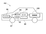
- FIG. 19 shows an example in which a power supply device is mounted on a hybrid vehicle that runs with both an engine and a motor.
- a vehicle HV equipped with the power supply device shown in this figure includes an engine 96 and a travel motor 93 that travel the vehicle HV, a power supply device 100 that supplies power to the motor 93, and a generator that charges a battery of the power supply device 100.
- 94 a vehicle main body 90 on which the power supply device 100 and the motor 93 are mounted, and wheels 97 that are driven by the motor 93 and run the vehicle main body.
- the power supply apparatus 100 is connected to a motor 93 and a generator 94 via a DC / AC inverter 95.
- the vehicle HV travels by both the motor 93 and the engine 96 while charging / discharging the battery of the power supply device 100.
- the motor 93 is driven to drive the vehicle when the engine efficiency is low, for example, during acceleration or low-speed driving.
- the motor 93 is driven by power supplied from the power supply device 100.
- the generator 94 is driven by the engine 96 or is driven by regenerative braking when the vehicle is braked to charge the battery of the power supply device 100. (Power supply for electric vehicles)
- FIG. 20 shows an example in which a power supply device is mounted on an electric vehicle that runs only with a motor.
- a vehicle EV equipped with the power supply device shown in this figure includes a traveling motor 93 for traveling the vehicle EV, a power supply device 100 that supplies power to the motor 93, and a generator 94 that charges a battery of the power supply device 100.
- the power supply apparatus 100 is connected to a motor 93 and a generator 94 via a DC / AC inverter 95.
- the motor 93 is driven by power supplied from the power supply device 100.
- the generator 94 is driven by energy when regeneratively braking the vehicle EV and charges the battery of the power supply device 100. (Power storage device for power storage)
- this power supply device can be used not only as a power source for moving bodies but also as a stationary power storage facility.
- a power source for home and factory use a power supply system that is charged with sunlight or midnight power and discharged when necessary, or a streetlight power supply that charges sunlight during the day and discharges at night, or during a power outage It can also be used as a backup power source for driving signals.
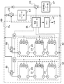
- FIG. The power supply apparatus 100 shown in this figure forms a battery unit 82 by connecting a plurality of battery packs 81 in a unit shape. Each battery pack 81 has a plurality of battery cells connected in series and / or in parallel. Each battery pack 81 is controlled by a power controller 84.
- the power supply apparatus 100 drives the load LD after charging the battery unit 82 with the charging power supply CP. For this reason, the power supply apparatus 100 includes a charging mode and a discharging mode.
- the load LD and the charging power source CP are connected to the power supply device 100 via the discharging switch DS and the charging switch CS, respectively.
- ON / OFF of the discharge switch DS and the charge switch CS is switched by the power supply controller 84 of the power supply apparatus 100.
- the power supply controller 84 switches the charging switch CS to ON and the discharging switch DS to OFF to permit charging from the charging power supply CP to the power supply apparatus 100.
- the power controller 84 turns off the charging switch CS and turns on the discharging switch DS to discharge.
- the mode is switched to permit discharge from the power supply apparatus 100 to the load LD.
- the charge switch CS can be turned on and the discharge switch DS can be turned on to supply power to the load LD and charge the power supply device 100 at the same time.
- the load LD driven by the power supply device 100 is connected to the power supply device 100 via the discharge switch DS.
- the power supply controller 84 switches the discharge switch DS to ON, connects to the load LD, and drives the load LD with the power from the power supply apparatus 100.
- the discharge switch DS a switching element such as an FET can be used. ON / OFF of the discharge switch DS is controlled by the power supply controller 84 of the power supply apparatus 100.
- the power controller 84 also includes a communication interface for communicating with external devices.
- the host device HT is connected in accordance with an existing communication protocol such as UART or RS-232C. Further, if necessary, a user interface for the user to operate the power supply system can be provided.
- Each battery pack 81 includes a signal terminal and a power supply terminal.
- the signal terminals include a pack input / output terminal DI, a pack abnormality output terminal DA, and a pack connection terminal DO.
- the pack input / output terminal DI is a terminal for inputting / outputting signals from other pack batteries and the power supply controller 84
- the pack connection terminal DO is for inputting / outputting signals to / from other pack batteries which are child packs.
- the pack abnormality output terminal DA is a terminal for outputting the abnormality of the battery pack to the outside.
- the power supply terminal is a terminal for connecting the battery packs 81 in series and in parallel.
- a power supply device, an electric vehicle including the power supply device, a power storage device, and a method for manufacturing the power supply device according to the present invention include a plug-in hybrid electric vehicle, a hybrid electric vehicle, and an electric vehicle that can switch between an EV traveling mode and an HEV traveling mode. It can utilize suitably as power supplies, such as. Also, a backup power supply device that can be mounted on a rack of a computer server, a backup power supply device for a wireless base station such as a mobile phone, a power storage device for home use and a factory, a power supply for a street light, etc. Also, it can be used as appropriate for applications such as a backup power source such as a traffic light.
- Vehicle main body 93 ... Motor 94 ... Generator 95 ... DC / AC inverter 96 ... Engine 97 ... Wheel 221 ... Battery cell 223 ... End plate 224 ... Bind bar BP ... Base plate g ... Gap JG ... Jig EV, HV ... Vehicle LD ... Load CP ... Charging power source DS ... Discharge switch CS ... Charge switch OL ... Output line HT ... Host device DI ... Pack input / output terminal; DA ... Pack abnormal output terminal; DO ... Pack Connecting terminal
Landscapes
- Engineering & Computer Science (AREA)
- Chemical & Material Sciences (AREA)
- General Chemical & Material Sciences (AREA)
- Electrochemistry (AREA)
- Chemical Kinetics & Catalysis (AREA)
- Power Engineering (AREA)
- Sustainable Development (AREA)
- Mechanical Engineering (AREA)
- Transportation (AREA)
- Sustainable Energy (AREA)
- Life Sciences & Earth Sciences (AREA)
- Manufacturing & Machinery (AREA)
- Aviation & Aerospace Engineering (AREA)
- Battery Mounting, Suspending (AREA)
- Connection Of Batteries Or Terminals (AREA)
Abstract
Description
(実施の形態1)
(バスバーホルダ8)
(中間ホルダ8A、側面ホルダ8B)
(嵌合構造30)
(爪部31)
(実施の形態2)
(締結手段4)
(第一バインドバー4A、第二バインドバー4B)
(上面被覆部4c)
(絶縁シート54)
(コ字状スリット8c)
(中間固定機構)
(中間固定突起4e)
(凹部8b)
(中間保持部)
(バインド穴4d)
(第二バインドバー4B)
(締結手段4とエンドプレート3との係止構造)
(プレート係止部42)
(ギャップg)
(ボルト固定穴4i)
(電池セル1)
(スペーサ15)
(スペーサ穴部15b)
(バスバー14)
(電圧検出線)
(バスバーホルダ8)
(中間ホルダ8A)
(位置決めガイド16)
(絶縁部17)
(ガスダクト)
(回路基板9)
(基板位置決めボス50)
(ホルダカバー20)
中間ホルダ8Aに設けた基板位置決めボス50は、ホルダカバー20を中間ホルダ8Aと螺合するためのねじ穴を開口している。これにより、基板位置決めボス50でもって回路基板9の固定とホルダカバー20の固定とを同時に行え、回路基板9をバスバー14の上面に位置決めして固定することができる。(電源装置の製造方法)
(ハイブリッド車用電源装置)
(電気自動車用電源装置)
(蓄電用電源装置)
1…電池セル
2…電池積層体
3、3C…エンドプレート;3b…エンドプレート貫通穴
4…締結手段;4A…第一バインドバー;4B…第二バインドバー;4a…側面被覆部;
4b…連結部;4c…上面被覆部;4d…バインド穴;4e…中間固定突起;4f…折曲
片;4g…バインド係止孔;4h…水平折曲片;4i…ボルト固定穴
6…ガスダクト
8…バスバーホルダ;8A、8A’…中間ホルダ;8B、8B’…側面ホルダ;8a…係
止スリット;8b…凹部;8c…コ字状スリット
9…回路基板
13…電極端子
14…バスバー
15…スペーサ;15b…スペーサ穴部
16…位置決めガイド
17…絶縁部
20…ホルダカバー
24…開口窓
30…嵌合構造
31、31’…爪部
32、32’…係止片
33b…ねじ;33c…リベット
42…プレート係止部;42a…第一プレート係止部;42b…第二プレート係止部
50…基板位置決めボス
51…ねじ
54…絶縁シート
56…ボルト
81…電池パック
82…電池ユニット
84…電源コントローラ
85…並列接続スイッチ
90…車両本体
93…モータ
94…発電機
95…DC/ACインバータ
96…エンジン
97…車輪
221…電池セル
223…エンドプレート
224…バインドバー
BP…ベースプレート
g…ギャップ
JG…治具
EV、HV…車両
LD…負荷
CP…充電用電源
DS…放電スイッチ
CS…充電スイッチ
OL…出力ライン
HT…ホスト機器
DI…パック入出力端子;DA…パック異常出力端子;DO…パック接続端子
Claims (18)
- それぞれが角形で、電極端子を備える複数の電池セルと、
前記電池セルを積層した電池積層体を締結する締結手段と、
前記電池セルの電極端子同士を接続するバスバーと、
前記電池積層体の上面を被覆する絶縁性のバスバーホルダとを備える電源装置であって、
前記締結手段が、前記電池積層体をその側面及び上面において締結するものであり、
さらに前記締結手段が、前記電池積層体の側面を被覆する側面被覆部と、上面を被覆する上面被覆部を備えており、
前記バスバーホルダが、中間に位置する中間ホルダと、前記中間ホルダの両側の側面にそれぞれ位置する側面ホルダとに分割されており、
前記側面ホルダと中間ホルダとは、互いに嵌合させるための嵌合構造を備えてなることを特徴とする電源装置。 - 請求項1に記載の電源装置であって、
前記嵌合構造が、前記中間ホルダと側面ホルダとを接合させる界面において、一方の面から突出させた爪部と、他方の面で該爪部を受ける係止片とで構成されてなることを特徴とする電源装置。 - 請求項1又は2に記載の電源装置であって、
前記バスバーホルダが、前記電池セルの積層方向に延長されており、
前記バスバーホルダが、該延長方向において、前記中間ホルダと側面ホルダとに分割されてなることを特徴とする電源装置。 - 請求項1から3のいずれか一に記載の電源装置であって、
前記締結手段が、前記電池積層体の側面において、垂直方向に離間して配置される、第一バインドバーと第二バインドバーとで構成されてなることを特徴とする電源装置。 - 請求項1から4のいずれか一に記載の電源装置であって、さらに、
前記締結手段と、前記電池積層体と間に介在される、絶縁性の絶縁シートを備えることを特徴とする電源装置。 - 請求項1から5のいずれか一に記載の電源装置であって、
前記側面ホルダが、前記上面被覆部の端縁を挿入可能に側面を開口した、断面視コ字状としたコ字状スリットを形成してなることを特徴とする電源装置。 - 請求項1から6のいずれか一に記載の電源装置であって、
前記締結手段は、中間部分において、前記中間ホルダ側に突出させた中間固定突起を設けており、
前記中間ホルダは、前記中間固定突起と対応する位置に、該中間固定突起を保持する中間保持部を設けてなることを特徴とする電源装置。 - 請求項7に記載の電源装置であって、
前記中間固定突起が、前記締結手段の一部を、前記側面ホルダを跨いで延長させ、かつ前記中間ホルダに向かって突出するよう折曲させた折曲片であり、
前記中間保持部が、前記折曲片を挿入するスリットであることを特徴とする電源装置。 - 請求項8に記載の電源装置であって、
前記側面ホルダが、前記折曲片を保持する凹部を形成してなることを特徴とする電源装置。 - 請求項1から9のいずれか一に記載の電源装置であって、
前記締結手段は、一以上のバインド穴を開口してなることを特徴とする電源装置。 - 請求項1から10のいずれか一に記載の電源装置であって、
前記バスバーホルダは、前記バスバーを配置する位置決めガイドを開口しており、
各位置決めガイド内に、それぞれ格子状の絶縁部を設けてなることを特徴とする電源装置。 - 請求項1から11のいずれか一に記載の電源装置であって、さらに、
前記電池積層体の、前記電池セル同士の間に介在される絶縁性のスペーサを備えており、
前記スペーサは、中央にスペーサ穴部を設けてなることを特徴とする電源装置。 - 請求項12に記載の電源装置であって、さらに、
前記スペーサは、前記スペーサ穴部を貫通孔としてなることを特徴とする電源装置。 - 請求項1から13のいずれか一に記載の電源装置であって、さらに、
前記バスバーホルダの上面に固定される、前記電池セルを監視する電子回路を実装した回路基板を備えており、
前記バスバーホルダは、その中央に、前記回路基板と固定するための基板位置決めボスを設けており、
前記基板位置決めボスは、その周囲に、前記回路基板を保持する保持突起を形成してなることを特徴とする電源装置。 - 請求項14に記載の電源装置であって、さらに、
前記回路基板の上面を被覆するホルダカバーを備えており、
前記基板位置決めボスは、前記ホルダカバーをバスバーホルダと螺合するためのねじ穴を開口してなることを特徴とする電源装置。 - 請求項1から15のいずれか一に記載の電源装置を備える電動車両であって、
前記電源装置から電力供給される走行用のモータと、
前記電源装置及び前記モータを搭載してなる車両本体と、
前記モータで駆動されて前記車両本体を走行させる車輪とを備えることを特徴とする電動車両。 - 請求項1から15のいずれか一に記載の電源装置を備える蓄電装置であって、
前記電源装置への充放電を制御する電源コントローラを備えており、
前記電源コントローラでもって、外部からの電力により前記電池モジュールへの充電を可能とすると共に、前記電池モジュールに対し充電を行うよう制御することを特徴とする蓄電装置。 - それぞれが角形で、電極端子を備える複数の電池セルと、
前記電池セルを積層した電池積層体を締結する締結手段と、
前記電池セルの電極端子同士を接続するバスバーと、
前記電池積層体の上面を被覆する絶縁性のバスバーホルダとを備え、
前記バスバーホルダが、中間の中間ホルダと、両側側面の側面ホルダとに分割されてなる電源装置の製造方法であって、
前記側面ホルダを前記電池積層体の上面の隅部にそれぞれ配置した状態で、前記締結手段で該側面ホルダの上面を締結する工程と、
前記側面ホルダ同士の間に、前記中間ホルダを、該側面ホルダと中間ホルダとの接合界面に設けられた嵌合構造によって嵌合して固定する工程と、
前記中間ホルダに形成された、前記バスバーを配置するための位置決めガイドに配置されたバスバーを、前記電池セルの前記電極端子と固定する工程と
を含むことを特徴とする電源装置の製造方法。
Priority Applications (2)
| Application Number | Priority Date | Filing Date | Title |
|---|---|---|---|
| JP2014532781A JP6234929B2 (ja) | 2012-08-30 | 2013-08-26 | 電源装置及び電源装置を備える車両並びに蓄電装置、電源装置の製造方 |
| US14/408,547 US9616766B2 (en) | 2012-08-30 | 2013-08-26 | Power source device, vehicle provided with power source device, and power storage device |
Applications Claiming Priority (2)
| Application Number | Priority Date | Filing Date | Title |
|---|---|---|---|
| JP2012-189743 | 2012-08-30 | ||
| JP2012189743 | 2012-08-30 |
Publications (1)
| Publication Number | Publication Date |
|---|---|
| WO2014034079A1 true WO2014034079A1 (ja) | 2014-03-06 |
Family
ID=50182916
Family Applications (1)
| Application Number | Title | Priority Date | Filing Date |
|---|---|---|---|
| PCT/JP2013/005015 Ceased WO2014034079A1 (ja) | 2012-08-30 | 2013-08-26 | 電源装置及び電源装置を備える車両並びに蓄電装置 |
Country Status (3)
| Country | Link |
|---|---|
| US (1) | US9616766B2 (ja) |
| JP (1) | JP6234929B2 (ja) |
| WO (1) | WO2014034079A1 (ja) |
Cited By (32)
| Publication number | Priority date | Publication date | Assignee | Title |
|---|---|---|---|---|
| KR20150117920A (ko) * | 2014-04-11 | 2015-10-21 | 삼성에스디아이 주식회사 | 배터리 모듈 |
| WO2015170580A1 (ja) * | 2014-05-07 | 2015-11-12 | 株式会社 豊田自動織機 | 電池モジュール |
| GB2529612A (en) * | 2014-06-25 | 2016-03-02 | R & D Vehicle Systems Ltd | Device for a battery assembly |
| JP2016051511A (ja) * | 2014-08-28 | 2016-04-11 | 株式会社豊田自動織機 | 電池パック |
| EP3021378A4 (en) * | 2013-07-12 | 2016-07-06 | Yazaki Corp | POWER SOURCE DEVICE |
| WO2016208184A1 (ja) * | 2015-06-22 | 2016-12-29 | カルソニックカンセイ株式会社 | 組電池及び電源装置 |
| WO2017013883A1 (ja) * | 2015-07-22 | 2017-01-26 | ソニー株式会社 | 電池モジュール、電動工具および電子機器 |
| CN106489213A (zh) * | 2014-07-09 | 2017-03-08 | 罗伯特·博世有限公司 | 用于承载和保持特别是用于电的车辆的电池组模块的电池组电池的组件的承载装置 |
| JPWO2016002178A1 (ja) * | 2014-07-02 | 2017-04-27 | 三洋電機株式会社 | 電源装置 |
| JP2017526130A (ja) * | 2014-08-19 | 2017-09-07 | ローベルト ボッシュ ゲゼルシャフト ミット ベシュレンクテル ハフツング | バッテリモジュールのための収容器、及び、このような収容器を有するバッテリモジュール |
| CN107251262A (zh) * | 2015-01-05 | 2017-10-13 | 江森自控科技公司 | 用于蓄电池模块的偏置特征 |
| JPWO2016136248A1 (ja) * | 2015-02-27 | 2017-12-07 | 三洋電機株式会社 | 電源装置及びこれを備える車両 |
| JP2018055889A (ja) * | 2016-09-27 | 2018-04-05 | 株式会社Gsユアサ | 蓄電装置 |
| CN108258168A (zh) * | 2018-03-21 | 2018-07-06 | 湖南金杯新能源发展有限公司 | 方形电芯模组 |
| US20180277820A1 (en) * | 2015-04-13 | 2018-09-27 | Johnson Controls Technology Company | Flexible ribs of a bus bar carrier |
| WO2018235556A1 (ja) * | 2017-06-22 | 2018-12-27 | 三洋電機株式会社 | 電源装置及びこれを備える車両並びに蓄電装置 |
| WO2019017062A1 (ja) * | 2017-07-18 | 2019-01-24 | 矢崎総業株式会社 | 電池モジュール及び電池監視ユニット搭載構造 |
| JP2019106318A (ja) * | 2017-12-13 | 2019-06-27 | パナソニックIpマネジメント株式会社 | 組電池 |
| JP2019169313A (ja) * | 2018-03-22 | 2019-10-03 | トヨタ自動車株式会社 | 全固体電池 |
| WO2019187316A1 (ja) * | 2018-03-30 | 2019-10-03 | 三洋電機株式会社 | 電源装置と電源装置を備える電動車両 |
| JP2020177935A (ja) * | 2020-08-06 | 2020-10-29 | パナソニックIpマネジメント株式会社 | 組電池 |
| CN111902961A (zh) * | 2018-03-27 | 2020-11-06 | 松下知识产权经营株式会社 | 蓄电模块 |
| CN112103585A (zh) * | 2015-01-05 | 2020-12-18 | Cps科技控股有限公司 | 用于电池模块的偏置特征 |
| JPWO2020261727A1 (ja) * | 2019-06-28 | 2020-12-30 | ||
| JPWO2019187315A1 (ja) * | 2018-03-30 | 2021-03-25 | 三洋電機株式会社 | 電源装置と電源装置を備える電動車両 |
| JP2021057149A (ja) * | 2019-09-27 | 2021-04-08 | トヨタ自動車株式会社 | 電池スタック及びその製造方法 |
| US11223093B2 (en) | 2017-12-14 | 2022-01-11 | Lg Chem, Ltd. | Battery module comprising bus bar assembly |
| CN114245950A (zh) * | 2019-10-14 | 2022-03-25 | 株式会社Lg新能源 | 电池组及其制造方法 |
| US11495845B2 (en) | 2018-03-23 | 2022-11-08 | Gs Yuasa International Ltd. | Energy storage apparatus |
| US11996575B2 (en) | 2018-06-22 | 2024-05-28 | Gs Yuasa International Ltd. | Energy storage apparatus |
| WO2025070098A1 (ja) | 2023-09-27 | 2025-04-03 | パナソニックIpマネジメント株式会社 | 電源システム |
| US12362412B2 (en) | 2021-04-05 | 2025-07-15 | Prime Planet Energy & Solutions, Inc. | Power storage module structural member, power storage module including power storage module structural member, and method of manufacturing power storage module structural member |
Families Citing this family (47)
| Publication number | Priority date | Publication date | Assignee | Title |
|---|---|---|---|---|
| US9520730B2 (en) * | 2013-12-17 | 2016-12-13 | Ford Global Technologies, Llc | Method and system for charging high voltage battery packs |
| JP6132937B2 (ja) * | 2014-02-14 | 2017-05-24 | 矢崎総業株式会社 | バスバモジュール |
| US10312485B2 (en) * | 2015-07-23 | 2019-06-04 | Ford Global Technologies, Llc | Battery assembly array plate |
| US10763469B2 (en) * | 2015-09-18 | 2020-09-01 | Gs Yuasa International Ltd. | Energy storage apparatus |
| KR102092268B1 (ko) * | 2015-11-30 | 2020-03-23 | 주식회사 엘지화학 | 클램핑 부재 및 이를 이용한 배터리 모듈 |
| US10573863B2 (en) * | 2016-02-24 | 2020-02-25 | Phillips & Temro Industries Inc. | Battery and auxiliary power unit mounting system |
| CN105742539B (zh) | 2016-04-21 | 2019-04-05 | 宁德时代新能源科技股份有限公司 | 一种电芯模组 |
| WO2018033880A2 (en) | 2016-08-17 | 2018-02-22 | Shape Corp. | Battery support and protection structure for a vehicle |
| JP6899637B2 (ja) * | 2016-09-07 | 2021-07-07 | 株式会社クボタ | バッテリパック |
| KR102172516B1 (ko) * | 2016-12-14 | 2020-10-30 | 주식회사 엘지화학 | 조립 구조가 개선된 공냉식 배터리 팩 |
| EP3566253B1 (en) | 2017-01-04 | 2022-12-28 | Shape Corp. | Battery support structure for a vehicle |
| DE102017200311A1 (de) * | 2017-01-10 | 2018-07-12 | Bayerische Motoren Werke Aktiengesellschaft | Batterie, Trägerboard und Trägerboardelement mit Rastelementen |
| CN108666462A (zh) * | 2017-03-30 | 2018-10-16 | 奥动新能源汽车科技有限公司 | 动力电池模组 |
| US10483510B2 (en) | 2017-05-16 | 2019-11-19 | Shape Corp. | Polarized battery tray for a vehicle |
| US10886513B2 (en) | 2017-05-16 | 2021-01-05 | Shape Corp. | Vehicle battery tray having tub-based integration |
| US11211656B2 (en) | 2017-05-16 | 2021-12-28 | Shape Corp. | Vehicle battery tray with integrated battery retention and support feature |
| WO2019055658A2 (en) | 2017-09-13 | 2019-03-21 | Shape Corp. | VEHICLE BATTERY TRAY WITH TUBULAR PERIPHERAL WALL |
| US12347879B2 (en) | 2017-09-13 | 2025-07-01 | Shape Corp. | Vehicle battery tray with tubular peripheral wall |
| WO2019054079A1 (ja) * | 2017-09-14 | 2019-03-21 | 日立オートモティブシステムズ株式会社 | 電池モジュール |
| US10661646B2 (en) | 2017-10-04 | 2020-05-26 | Shape Corp. | Battery tray floor assembly for electric vehicles |
| KR102280997B1 (ko) * | 2017-12-20 | 2021-07-22 | 주식회사 엘지에너지솔루션 | 전지 모듈 및 이를 포함하는 전지팩 |
| CN109994663B (zh) * | 2017-12-29 | 2021-09-14 | 宁德时代新能源科技股份有限公司 | 复合端板以及电池模组 |
| JP6979372B2 (ja) * | 2018-02-26 | 2021-12-15 | ビークルエナジージャパン株式会社 | 電池モジュール |
| CN112055898A (zh) | 2018-03-01 | 2020-12-08 | 形状集团 | 与车辆电池托盘集成的冷却系统 |
| US11688910B2 (en) | 2018-03-15 | 2023-06-27 | Shape Corp. | Vehicle battery tray having tub-based component |
| US11929479B2 (en) * | 2018-07-31 | 2024-03-12 | Sanyo Electric Co., Ltd. | Power supply device, vehicle having same, and buffer |
| EP3855526B1 (en) * | 2018-09-20 | 2025-03-05 | SANYO Electric Co., Ltd. | Power supply device, vehicle having power supply device, and power storage device |
| KR102250193B1 (ko) | 2018-10-10 | 2021-05-07 | 주식회사 엘지화학 | 공간 절약형 icb 조립체를 적용한 배터리 모듈 |
| CN115117563B (zh) * | 2018-12-29 | 2024-04-02 | 东莞莫仕连接器有限公司 | 电池连接模块 |
| JP7062604B2 (ja) * | 2019-02-12 | 2022-05-06 | 本田技研工業株式会社 | バッテリモジュール |
| US12136719B2 (en) * | 2019-08-03 | 2024-11-05 | Sanyo Electric Co., Ltd. | Power supply device, electric vehicle comprising said power supply device, and power storage device |
| WO2021199489A1 (ja) * | 2020-03-30 | 2021-10-07 | 三洋電機株式会社 | 電池モジュール、電池モジュールを備える電動車両及び蓄電装置 |
| US20230170575A1 (en) * | 2020-03-31 | 2023-06-01 | Sanyo Electric Co., Ltd. | Power source device, and vehicle and power storage device each equipped with same |
| US20210362849A1 (en) | 2020-05-19 | 2021-11-25 | Archer Aviation, Inc. | Vertical take-off and landing aircraft |
| US11661180B2 (en) | 2020-07-08 | 2023-05-30 | Archer Aviation Inc. | Systems and methods for power distribution in electric aircraft |
| JP7580575B2 (ja) * | 2020-10-19 | 2024-11-11 | ジアンス・コンテンポラリー・アンプレックス・テクノロジー・リミテッド | 電池、電気装置、電池の製造方法および装置 |
| US11465764B2 (en) | 2020-12-08 | 2022-10-11 | Archer Aviation, Inc. | Systems and methods for power distribution in electric aircraft |
| US11465532B2 (en) | 2021-01-22 | 2022-10-11 | Archer Aviation, Inc. | Systems and methods for power distribution in electric aircraft |
| US11919631B2 (en) | 2021-02-08 | 2024-03-05 | Archer Aviation, Inc. | Vertical take-off and landing aircraft with aft rotor tilting |
| KR102862209B1 (ko) * | 2021-06-08 | 2025-09-18 | 주식회사 엘지에너지솔루션 | 절연 냉각액을 이용한 냉각 구조를 갖는 배터리 모듈, 그리고 이를 포함하는 배터리 팩 및 자동차 |
| JP7567682B2 (ja) * | 2021-06-23 | 2024-10-16 | トヨタ自動車株式会社 | 蓄電装置 |
| US11912123B2 (en) * | 2021-12-08 | 2024-02-27 | Ford Global Technologies, Llc | Traction battery pack venting system and venting method |
| JP7570366B2 (ja) * | 2022-03-01 | 2024-10-21 | プライムプラネットエナジー&ソリューションズ株式会社 | 電池モジュール |
| CN120359646A (zh) | 2022-11-14 | 2025-07-22 | 阿切尔航空公司 | 高压电池架构 |
| USD1127701S1 (en) * | 2023-03-31 | 2026-05-26 | Jinko Energy Storage Technology Co., Ltd | Energy storage module |
| DE102023004057A1 (de) * | 2023-10-11 | 2024-07-04 | Mercedes-Benz Group AG | Halterungsanordnung zur Halterung von Einzelzellen |
| CN222355372U (zh) * | 2024-01-02 | 2025-01-14 | 宁德时代新能源科技股份有限公司 | Ccs组件和具有其的电池及用电装置 |
Citations (6)
| Publication number | Priority date | Publication date | Assignee | Title |
|---|---|---|---|---|
| JP2003100273A (ja) * | 2001-09-25 | 2003-04-04 | Yazaki Corp | 電源装置 |
| JP2011091035A (ja) * | 2009-10-22 | 2011-05-06 | Sb Limotive Co Ltd | バッテリーパック及びバスバーホルダー |
| JP2012014962A (ja) * | 2010-06-30 | 2012-01-19 | Sanyo Electric Co Ltd | 組電池 |
| JP2012022937A (ja) * | 2010-07-15 | 2012-02-02 | Toshiba Corp | 二次電池装置 |
| WO2012057322A1 (ja) * | 2010-10-30 | 2012-05-03 | 三洋電機株式会社 | 組電池及びこれを用いた車両 |
| WO2013084941A1 (ja) * | 2011-12-09 | 2013-06-13 | 本田技研工業株式会社 | バッテリモジュール |
Family Cites Families (5)
| Publication number | Priority date | Publication date | Assignee | Title |
|---|---|---|---|---|
| US6275004B1 (en) * | 2000-09-11 | 2001-08-14 | General Motors Corporation | System for battery module balancing via variable voltage DC-DC converter in a hybrid-electric powertrain |
| JP5279226B2 (ja) * | 2007-09-27 | 2013-09-04 | 株式会社東芝 | 組電池 |
| JP5372449B2 (ja) * | 2008-09-24 | 2013-12-18 | 三洋電機株式会社 | バッテリシステム |
| KR101201747B1 (ko) * | 2010-05-24 | 2012-11-15 | 에스비리모티브 주식회사 | 전지 모듈 |
| JP6045198B2 (ja) * | 2011-06-08 | 2016-12-14 | 株式会社Gsユアサ | 電池パック |
-
2013
- 2013-08-26 US US14/408,547 patent/US9616766B2/en active Active
- 2013-08-26 WO PCT/JP2013/005015 patent/WO2014034079A1/ja not_active Ceased
- 2013-08-26 JP JP2014532781A patent/JP6234929B2/ja active Active
Patent Citations (6)
| Publication number | Priority date | Publication date | Assignee | Title |
|---|---|---|---|---|
| JP2003100273A (ja) * | 2001-09-25 | 2003-04-04 | Yazaki Corp | 電源装置 |
| JP2011091035A (ja) * | 2009-10-22 | 2011-05-06 | Sb Limotive Co Ltd | バッテリーパック及びバスバーホルダー |
| JP2012014962A (ja) * | 2010-06-30 | 2012-01-19 | Sanyo Electric Co Ltd | 組電池 |
| JP2012022937A (ja) * | 2010-07-15 | 2012-02-02 | Toshiba Corp | 二次電池装置 |
| WO2012057322A1 (ja) * | 2010-10-30 | 2012-05-03 | 三洋電機株式会社 | 組電池及びこれを用いた車両 |
| WO2013084941A1 (ja) * | 2011-12-09 | 2013-06-13 | 本田技研工業株式会社 | バッテリモジュール |
Cited By (59)
| Publication number | Priority date | Publication date | Assignee | Title |
|---|---|---|---|---|
| EP3021378A4 (en) * | 2013-07-12 | 2016-07-06 | Yazaki Corp | POWER SOURCE DEVICE |
| KR102248596B1 (ko) * | 2014-04-11 | 2021-05-06 | 삼성에스디아이 주식회사 | 배터리 모듈 |
| KR20150117920A (ko) * | 2014-04-11 | 2015-10-21 | 삼성에스디아이 주식회사 | 배터리 모듈 |
| US9716255B2 (en) | 2014-05-07 | 2017-07-25 | Kabushiki Kaisha Toyota Jidoshokki | Battery module |
| WO2015170580A1 (ja) * | 2014-05-07 | 2015-11-12 | 株式会社 豊田自動織機 | 電池モジュール |
| JP2015213039A (ja) * | 2014-05-07 | 2015-11-26 | 株式会社豊田自動織機 | 電池モジュール |
| GB2529612A (en) * | 2014-06-25 | 2016-03-02 | R & D Vehicle Systems Ltd | Device for a battery assembly |
| JPWO2016002178A1 (ja) * | 2014-07-02 | 2017-04-27 | 三洋電機株式会社 | 電源装置 |
| CN106489213B (zh) * | 2014-07-09 | 2020-01-03 | 罗伯特·博世有限公司 | 用于承载和保持特别是用于电的车辆的电池组模块的电池组电池的组件的承载装置 |
| EP3167498B1 (de) * | 2014-07-09 | 2022-12-21 | Robert Bosch GmbH | Trägeranordnung zum tragen und halten von komponenten für batteriezellen eines batteriemoduls, insbesondere für ein elektrisches fahrzeug |
| CN106489213A (zh) * | 2014-07-09 | 2017-03-08 | 罗伯特·博世有限公司 | 用于承载和保持特别是用于电的车辆的电池组模块的电池组电池的组件的承载装置 |
| JP2017526130A (ja) * | 2014-08-19 | 2017-09-07 | ローベルト ボッシュ ゲゼルシャフト ミット ベシュレンクテル ハフツング | バッテリモジュールのための収容器、及び、このような収容器を有するバッテリモジュール |
| JP2016051511A (ja) * | 2014-08-28 | 2016-04-11 | 株式会社豊田自動織機 | 電池パック |
| US11063326B2 (en) | 2015-01-05 | 2021-07-13 | CPS Technology Holdings LL | Biasing features for a battery module |
| US10199631B2 (en) * | 2015-01-05 | 2019-02-05 | Johnson Controls Technology Company | Biasing features for a battery module |
| CN112103585A (zh) * | 2015-01-05 | 2020-12-18 | Cps科技控股有限公司 | 用于电池模块的偏置特征 |
| CN107251262A (zh) * | 2015-01-05 | 2017-10-13 | 江森自控科技公司 | 用于蓄电池模块的偏置特征 |
| JPWO2016136248A1 (ja) * | 2015-02-27 | 2017-12-07 | 三洋電機株式会社 | 電源装置及びこれを備える車両 |
| US20180277820A1 (en) * | 2015-04-13 | 2018-09-27 | Johnson Controls Technology Company | Flexible ribs of a bus bar carrier |
| WO2016208184A1 (ja) * | 2015-06-22 | 2016-12-29 | カルソニックカンセイ株式会社 | 組電池及び電源装置 |
| CN107851752B (zh) * | 2015-07-22 | 2020-09-18 | 株式会社村田制作所 | 电池模块、电动工具及电子设备 |
| US10734617B2 (en) | 2015-07-22 | 2020-08-04 | Murata Manufacturing Co., Ltd. | Battery module, power tool, and electronic apparatus |
| CN107851752A (zh) * | 2015-07-22 | 2018-03-27 | 株式会社村田制作所 | 电池模块、电动工具及电子设备 |
| WO2017013883A1 (ja) * | 2015-07-22 | 2017-01-26 | ソニー株式会社 | 電池モジュール、電動工具および電子機器 |
| JPWO2017013883A1 (ja) * | 2015-07-22 | 2018-05-24 | 株式会社村田製作所 | 電池モジュール、電動工具および電子機器 |
| JP2018055889A (ja) * | 2016-09-27 | 2018-04-05 | 株式会社Gsユアサ | 蓄電装置 |
| JP7039584B6 (ja) | 2017-06-22 | 2022-04-01 | 三洋電機株式会社 | 電源装置及びこれを備える車両並びに蓄電装置 |
| WO2018235556A1 (ja) * | 2017-06-22 | 2018-12-27 | 三洋電機株式会社 | 電源装置及びこれを備える車両並びに蓄電装置 |
| JP7039584B2 (ja) | 2017-06-22 | 2022-03-22 | 三洋電機株式会社 | 電源装置及びこれを備える車両並びに蓄電装置 |
| US11660951B2 (en) | 2017-06-22 | 2023-05-30 | Sanyo Electric Co., Ltd. | Power supply device, vehicle equipped with same, and electricity storage device |
| JPWO2018235556A1 (ja) * | 2017-06-22 | 2020-04-23 | 三洋電機株式会社 | 電源装置及びこれを備える車両並びに蓄電装置 |
| WO2019017062A1 (ja) * | 2017-07-18 | 2019-01-24 | 矢崎総業株式会社 | 電池モジュール及び電池監視ユニット搭載構造 |
| US11302984B2 (en) | 2017-07-18 | 2022-04-12 | Yazaki Corporation | Battery module and battery monitoring unit mounting structure |
| JP2019021500A (ja) * | 2017-07-18 | 2019-02-07 | 矢崎総業株式会社 | 電池モジュール及び電池監視ユニット搭載構造 |
| JP2019106318A (ja) * | 2017-12-13 | 2019-06-27 | パナソニックIpマネジメント株式会社 | 組電池 |
| US11223093B2 (en) | 2017-12-14 | 2022-01-11 | Lg Chem, Ltd. | Battery module comprising bus bar assembly |
| CN108258168A (zh) * | 2018-03-21 | 2018-07-06 | 湖南金杯新能源发展有限公司 | 方形电芯模组 |
| JP2019169313A (ja) * | 2018-03-22 | 2019-10-03 | トヨタ自動車株式会社 | 全固体電池 |
| JP7010102B2 (ja) | 2018-03-22 | 2022-01-26 | トヨタ自動車株式会社 | 全固体電池 |
| US11495845B2 (en) | 2018-03-23 | 2022-11-08 | Gs Yuasa International Ltd. | Energy storage apparatus |
| CN111902961A (zh) * | 2018-03-27 | 2020-11-06 | 松下知识产权经营株式会社 | 蓄电模块 |
| JP7207814B2 (ja) | 2018-03-30 | 2023-01-18 | 三洋電機株式会社 | 電源装置と電源装置を備える電動車両 |
| WO2019187316A1 (ja) * | 2018-03-30 | 2019-10-03 | 三洋電機株式会社 | 電源装置と電源装置を備える電動車両 |
| US11858362B2 (en) | 2018-03-30 | 2024-01-02 | Sanyo Electric Co., Ltd. | Power supply device and electric vehicle provided with power supply device |
| JPWO2019187315A1 (ja) * | 2018-03-30 | 2021-03-25 | 三洋電機株式会社 | 電源装置と電源装置を備える電動車両 |
| US11996575B2 (en) | 2018-06-22 | 2024-05-28 | Gs Yuasa International Ltd. | Energy storage apparatus |
| WO2020261727A1 (ja) * | 2019-06-28 | 2020-12-30 | 三洋電機株式会社 | 電源装置とこの電源装置を備える電動車両及び蓄電装置 |
| JPWO2020261727A1 (ja) * | 2019-06-28 | 2020-12-30 | ||
| JP7554743B2 (ja) | 2019-06-28 | 2024-09-20 | 三洋電機株式会社 | 電源装置とこの電源装置を備える電動車両及び蓄電装置 |
| US12355051B2 (en) | 2019-06-28 | 2025-07-08 | Sanyo Electric Co., Ltd. | Power supply device, electric vehicle comprising said power supply device, and power storage device |
| JP7226229B2 (ja) | 2019-09-27 | 2023-02-21 | トヨタ自動車株式会社 | 電池スタック及びその製造方法 |
| JP2021057149A (ja) * | 2019-09-27 | 2021-04-08 | トヨタ自動車株式会社 | 電池スタック及びその製造方法 |
| CN114245950B (zh) * | 2019-10-14 | 2024-02-06 | 株式会社Lg新能源 | 电池组及其制造方法 |
| CN114245950A (zh) * | 2019-10-14 | 2022-03-25 | 株式会社Lg新能源 | 电池组及其制造方法 |
| US12261314B2 (en) | 2019-10-14 | 2025-03-25 | Lg Energy Solution, Ltd. | Battery pack and manufacturing method thereof |
| JP2020177935A (ja) * | 2020-08-06 | 2020-10-29 | パナソニックIpマネジメント株式会社 | 組電池 |
| JP6994677B2 (ja) | 2020-08-06 | 2022-01-14 | パナソニックIpマネジメント株式会社 | 組電池 |
| US12362412B2 (en) | 2021-04-05 | 2025-07-15 | Prime Planet Energy & Solutions, Inc. | Power storage module structural member, power storage module including power storage module structural member, and method of manufacturing power storage module structural member |
| WO2025070098A1 (ja) | 2023-09-27 | 2025-04-03 | パナソニックIpマネジメント株式会社 | 電源システム |
Also Published As
| Publication number | Publication date |
|---|---|
| JPWO2014034079A1 (ja) | 2016-08-08 |
| US20150144409A1 (en) | 2015-05-28 |
| JP6234929B2 (ja) | 2017-11-22 |
| US9616766B2 (en) | 2017-04-11 |
Similar Documents
| Publication | Publication Date | Title |
|---|---|---|
| JP6234929B2 (ja) | 電源装置及び電源装置を備える車両並びに蓄電装置、電源装置の製造方 | |
| JP7039584B6 (ja) | 電源装置及びこれを備える車両並びに蓄電装置 | |
| JP5868676B2 (ja) | 電源装置及びこれを備える車両並びに蓄電装置 | |
| EP2988344B1 (en) | Battery module having novel structure and battery pack comprising same | |
| JP6328842B2 (ja) | 電源装置及びこれを備える車両 | |
| US9673430B2 (en) | Power source device, electric vehicle comprising power source device, accumulator device | |
| CN111527621B (zh) | 电源装置以及具备电源装置的车辆和蓄电装置 | |
| EP2919296B1 (en) | Battery module comprising bus bar assembly, and battery pack comprising same | |
| JP6017539B2 (ja) | 電源装置及びこれを備える車両並びに蓄電装置 | |
| JP6189301B2 (ja) | 電源装置及びこれを備える電動車両並びに蓄電装置 | |
| US20150125720A1 (en) | Power source device, electric vehicle provided with same, and electricity storage device | |
| JP2015207341A (ja) | 電源装置及び電源装置を備える電動車両並びに蓄電装置 | |
| JP6164279B2 (ja) | 電源装置 | |
| JP2013114951A (ja) | 電源装置及びこれを備える車両並びに蓄電装置、連結ユニット | |
| JP2012181970A (ja) | 電源装置及び電源装置を備える車両 | |
| WO2012057322A1 (ja) | 組電池及びこれを用いた車両 | |
| WO2014024430A1 (ja) | 電池パック及びこれを備える電動車両並びに蓄電装置 | |
| WO2014024450A1 (ja) | 電源装置及びこれを備える電動車両並びに蓄電装置 | |
| WO2019130937A1 (ja) | 電源装置及び電源装置を備える車両並びに蓄電装置 | |
| KR101750487B1 (ko) | 외부 입출력 단자 및 버스 바의 장착 수단을 포함하는 전지모듈 | |
| WO2014024451A1 (ja) | 電源装置及びこれを備える電動車両並びに蓄電装置 | |
| WO2014024426A1 (ja) | 電源装置及びこれを備える電動車両並びに蓄電装置 | |
| WO2014024449A1 (ja) | 電源装置の製造方法、電源装置及びこれを備える電動車両並びに蓄電装置 |
Legal Events
| Date | Code | Title | Description |
|---|---|---|---|
| 121 | Ep: the epo has been informed by wipo that ep was designated in this application |
Ref document number: 13834277 Country of ref document: EP Kind code of ref document: A1 |
|
| WWE | Wipo information: entry into national phase |
Ref document number: 14408547 Country of ref document: US |
|
| ENP | Entry into the national phase |
Ref document number: 2014532781 Country of ref document: JP Kind code of ref document: A |
|
| NENP | Non-entry into the national phase |
Ref country code: DE |
|
| 122 | Ep: pct application non-entry in european phase |
Ref document number: 13834277 Country of ref document: EP Kind code of ref document: A1 |