WO2014033923A1 - 抜型用打抜刃 - Google Patents
抜型用打抜刃 Download PDFInfo
- Publication number
- WO2014033923A1 WO2014033923A1 PCT/JP2012/072204 JP2012072204W WO2014033923A1 WO 2014033923 A1 WO2014033923 A1 WO 2014033923A1 JP 2012072204 W JP2012072204 W JP 2012072204W WO 2014033923 A1 WO2014033923 A1 WO 2014033923A1
- Authority
- WO
- WIPO (PCT)
- Prior art keywords
- punching
- blade
- arc surface
- cutting
- curvature
- Prior art date
- Legal status (The legal status is an assumption and is not a legal conclusion. Google has not performed a legal analysis and makes no representation as to the accuracy of the status listed.)
- Ceased
Links
Images






Classifications
-
- B—PERFORMING OPERATIONS; TRANSPORTING
- B26—HAND CUTTING TOOLS; CUTTING; SEVERING
- B26F—PERFORATING; PUNCHING; CUTTING-OUT; STAMPING-OUT; SEVERING BY MEANS OTHER THAN CUTTING
- B26F1/00—Perforating; Punching; Cutting-out; Stamping-out; Apparatus therefor
- B26F1/38—Cutting-out; Stamping-out
- B26F1/44—Cutters therefor; Dies therefor
-
- B—PERFORMING OPERATIONS; TRANSPORTING
- B26—HAND CUTTING TOOLS; CUTTING; SEVERING
- B26F—PERFORATING; PUNCHING; CUTTING-OUT; STAMPING-OUT; SEVERING BY MEANS OTHER THAN CUTTING
- B26F1/00—Perforating; Punching; Cutting-out; Stamping-out; Apparatus therefor
- B26F1/38—Cutting-out; Stamping-out
- B26F1/44—Cutters therefor; Dies therefor
- B26F2001/4472—Cutting edge section features
-
- B—PERFORMING OPERATIONS; TRANSPORTING
- B26—HAND CUTTING TOOLS; CUTTING; SEVERING
- B26F—PERFORATING; PUNCHING; CUTTING-OUT; STAMPING-OUT; SEVERING BY MEANS OTHER THAN CUTTING
- B26F1/00—Perforating; Punching; Cutting-out; Stamping-out; Apparatus therefor
- B26F1/38—Cutting-out; Stamping-out
- B26F1/44—Cutters therefor; Dies therefor
- B26F2001/4481—Cutters therefor; Dies therefor having special lateral or edge outlines or special surface shapes, e.g. apertures
Definitions
- the present invention relates to a punching blade for setting a die cutter (also referred to as a Thomson type) of a die cutter such as punching a sheet such as corrugated paper or paper board.
- a punching die for punching a sheet such as corrugated paper or paper board is configured by solidly planting a punching blade on a die plate made of thick plywood.
- the punching blade is, as shown in FIG. 13, generally sloped on both sides of one side edge of the constant-width, fixed-width, band-like blade base material 1 having a thickness of about 0.45 mm to 2 mm and a height of about 23.6 mm.
- the cutting edge 3 having an apex angle ⁇ of 30 degrees to 90 degrees was formed by grinding in the shape of a circle.
- the punching blade 4 in which both sides were formed in the shape of a slope has a problem that intensity
- the above-mentioned apex angle ⁇ and thickness of the punching blade are appropriately selected in accordance with the material of the material of the sheet to be punched out (cardboard paper, plastic sheet, etc.) so as to maintain appropriate strength and cutting performance.
- FIG. 14 shows a situation in which the cardboard S is punched out by the punching blade 4.
- the cut surfaces thereof are the shoulder portions 2 of the punching blade 4. , 2 and scrapes, and chips and paper dust are more likely to come off.
- an elastic body such as foam rubber is conventionally used on the die plate surface to separate the punched products and punched chips from the mold surface.
- the elastic body is compressed at the time of punching and is expanded in the lateral direction when the punched products and the punched chips are narrow, the elastic body is disposed at one side of the punching blade 4 though it is disposed. Since the punching blade 4 may be inclined sideways due to the pressing force and the pressing force, there is a problem that it can not withstand long-term use.
- the apex angle ⁇ of the conventional punching blade 4 is Since the above is not uniform due to the above reasons, the bed surface shape of the cutting machine which lays the punching blade 4 when cutting the punching blade is not necessarily the same as the side shape of the punching blade, and remains inconsistent When it is cut at this time, an extra bending force is applied to the punching blade 4 and there is a possibility that the punching blade is deformed.
- the present invention is intended to provide a punching die that can solve these problems.
- a cutting edge is formed on one side edge of a constant thickness, constant width, band plate-like blade base, and a portion extending from both sides of the cutting edge to both flat surfaces of the blade base bulges outward.
- a punching die for forming a die which is formed in a circular arc shape and the cutting edge is formed by the intersection of both circular arcs, and the center of curvature of each circular arc is orthogonal to both side planes of the cutter base.
- the blade base is set on two straight lines spaced apart in the width direction of the blade base, the tangential direction of each circular arc surface coincides with both side planes of the blade base, and the blade edge is of the blade base
- the radius of curvature of each of the circular arc surfaces is set to be formed on the center line in the thickness direction.
- the cutting edge is formed on one side edge of the blade base having a constant thickness and constant width band plate shape, and a portion extending from both sides of the blade to both flat surfaces of the cutter base is outward
- a punching die for forming a die which is formed into an arc surface which bulges into two and the cutting edge is formed by the intersection of both arcs, and the center of curvature of each arc is the both sides of the blade base. It is characterized in that it is set on a straight line orthogonal to the plane, and the radius of curvature of each arc surface is set so that the tangential direction of each arc surface coincides with the both side surfaces of the cutting substrate.
- the punching die according to the present invention wherein the cutting edges are continuously connected in a wave shape at a constant pitch in the longitudinal direction by alternately offsetting the cutting edges to both sides within the thickness range of the cutter base. It is characterized by being formed.
- a set of punching dies according to the present invention is the above-mentioned punching die for punching, and a plurality of punching blades of different thickness are used as one set, and the punching blades of each of the punching dies are provided. It is characterized in that the radius of curvature of at least one arc surface is set to be the same for any of the punching dies.
- the punching die according to the present invention chips, paper dust and the like generated when punching out a sheet can be reduced, and the strength of the blade base is increased, and even if a load is repeatedly applied over a long period, It is difficult for deformation such as crushing or buckling to occur, and the life is improved. Further, according to the punching die according to the present invention, since the ratio of chips, paper dust and the like adhering to the product side can be reduced, it is possible to make defective products less likely to occur. Further, since the punching die according to the present invention can be set so as not to tilt sideways even when pressed by the elastic body, it can endure long-term use.
- the punching die according to the present invention can always punch the sheet cleanly without bending the cutting edge into a strange curve or causing uneven height even when bent at a sharp angle such as a right angle. Further, in the set of punching dies according to the present invention, there is no possibility that any punching dies will be deformed when they are cut by the cutting machine.
- FIG. 2 is a perspective view of a blade base of the punching die according to the present invention.
- FIG. 2 is a perspective view of a punching die according to the present invention.
- BRIEF DESCRIPTION OF THE DRAWINGS The cross-sectional view of the principal part of the punching blade which concerns on this invention.
- BRIEF DESCRIPTION OF THE DRAWINGS The longitudinal cross-sectional view of the punching die which solidified the punching blade for mold release which concerns on this invention.
- BRIEF DESCRIPTION OF THE DRAWINGS Fig. 1 is a cross-sectional view of a punching die according to the present invention at the time of punching a corrugated paper.
- FIG. 1 is a cross-sectional view of a punching die according to the present invention.
- BRIEF DESCRIPTION OF THE DRAWINGS The cross-sectional view of the principal part of the punching blade which concerns on this invention.
- FIG. 2 is a perspective view of the punching die according to the present invention bent at a right angle.
- FIG. 2 is a plan view of the punching die according to the present invention bent at a right angle.
- FIG. 2 is a perspective view of a punching die according to the present invention.
- FIG. 2 is a plan view of a punching die according to the present invention.
- BRIEF DESCRIPTION OF THE DRAWINGS The cross-sectional view of the bed of the cutting machine which cut-processes the punching blade which concerns on this invention.
- FIG. 10 is a cross-sectional view of a conventional punching die for punching a corrugated paper; The perspective view at the time of bending the conventional punching blade at right angles. The top view at the time of bend
- FIG. 1 shows a blade substrate 1 made of carbon steel and having a thickness t and a constant width and a constant width strip plate.
- a sharp cutting edge 3 is formed at one side edge of the blade base 1, and from the cutting edge 3 both sides of the blade base
- the portion extending over the flat surfaces 5a and 5b is in the form of a circular arc surface that bulges outward, and the cutting edge 3 is formed by the intersection of the two circular arc surfaces 6a and 6b.
- the detail of this punching blade 4 is expanded and shown to the cross-sectional view of FIG.
- the center of curvature 7a of one arc surface 6a is set on a straight line 8a orthogonal to both side flat surfaces 5a and 5b of the cutter base 1, and the center of curvature 7b of the other arc surface 6b is a straight line It is set on a straight line 8b parallel to 8a and separated by an interval g. Further, the tangential direction of each arc surface 6a, 6b coincides with both side flat surfaces 5a, 5b of the cutter base 1, and the blade edge 3 intersects both the arc surfaces 6a, 6b.
- the curvature radiuses Ra and Rb of the arc surfaces 6a and 6b are set to be formed on the longitudinal center line c.
- the distance La from the cutting edge 3 to the straight line 8a is 1.276 mm
- the distance Lb from the cutting edge 3 to the straight line 8b is 1.13 mm
- the blade base 1 is formed by setting Ra to 2 mm and the radius of curvature Rb to 2.5 mm.
- the elastic body 9 is disposed on the side having the large radius of curvature (in this case, the side of the arc surface 6 a) as necessary.
- a load larger than the circular arc surface 6a is applied to the circular arc surface 6b from the corrugated paper S during punching, while a pressing force from the elastic body 9 is applied to the side plane 5a on the circular arc surface 6a side.
- the punching blade 4 can be prevented from tilting to one side during use. For this reason, stable use can be maintained for a long time.
- the punching blade 4 pierces so that the arc surfaces 6a and 6b near the cutting edge 3 push the corrugated paper wider. It becomes difficult for the cut surface of the corrugated paper S to contact the portions corresponding to the two shoulders 2 and 2 of the punching blade. For this reason, as in the conventional case, the cut surface is rubbed to remove chips and paper dust, and thus the occurrence of defective products can be greatly suppressed.
- the strength of the cutting edge 3 is increased, and deformation such as crushing or buckling is less likely to occur even if a compressive load is repeatedly applied by punching the corrugated paper S, and the life span is shortened. Improve.
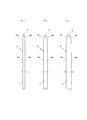
- FIG. 6 shows three types of blade base materials 1 having different thicknesses of the blade base material 1, and FIG. 3 (a) shows the case where the thickness t of the blade base material 1 is 0.5 mm, (b) Shows the case where the thickness t is 0.9 mm, and (c) shows the case where the thickness t is 1.2 mm.
- Each punching blade 4 is formed in an arc surface shape including arc surfaces 6a and 6b which bulge outward from both flat surfaces 5a and 5b of the cutter base 1 to the cutting edge, and the arc surfaces 6a and 6b are The blade edge 3 is formed on the center line in the thickness direction of the blade base 1 by intersecting at one side edge of the blade base 1.
- each of the punching blades 4 has a center of curvature 7 a, 7 b of the arc surfaces 6 a, 6 b at the boundary between the arc surfaces 6 a, 6 b and both flat surfaces 5 a, 5 b of the cutter base 1. It is set so as to be located on a straight line 8 orthogonal to both side planes 5a, 5b.
- the curvature radius Ra of the arc surface 6a and the curvature radius Rb of the arc surface 6b are set to be the same.
- the curvature radiuses Ra and Rb of the punching blades 4 are set to 3 mm regardless of the thickness t of the cutter base 1.
- the punching blade 4 configured in this manner, when the corrugated paper S is punched out, the arc surfaces 6a and 6b pierce the corrugated paper so as to push the corrugated paper wider, so that the generation of paper dust and the like can be suppressed. Since the strength of the cutting edge 3 is increased, deformation is difficult and the life is improved.
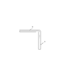
- the blade tip 3 is strongly supported from both sides by the arc surfaces 6a and 6b when bent at a right angle as shown in FIGS.
- the cutting edge 3 does not have a strange curve as in the prior art, and the height of the cutting edge 3 does not become uneven at this bent portion. For this reason, it is possible to always punch out sheets such as cardboard paper.
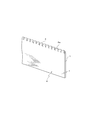
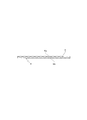
- the punching blade 4 shown in FIG. 10 and FIG. 11 continues in a wave form with a constant pitch in the longitudinal direction by alternately offsetting the blade edge 3 to both sides within the thickness range of the cutter base 1
- the cutting edge 3 is formed.
- the cutting edge of the sheet can be made into a wave-like shape. It is possible to suppress the occurrence of defective products without causing them.
- the wave pitch of the punching blade 4 is set to about 0.5 to 4 mm according to the application.
- FIG. 12 shows a bed 10 of a cutting machine for cutting this punching blade 4 into appropriate lengths.
- the bed 10 is formed in an arc surface having the same radius of curvature as the radii of curvature Ra and Rb of the arc surfaces 6 a and 6 b of the punching blade 4. Therefore, when the punching blade 4 is laid on the bed 10, the arc surface 6a and the side flat surface 5a, or the arc surface 6b and the side flat surface 5b can be closely adhered to the surface 10a without a gap. Since it is stably supported, there is no possibility of deforming the punching blade 4 without an unnecessary bending force being applied to the punching blade 4 at the time of cutting.
- the arcs of the surface 10a of the bed 10 of the cutting machine are made equal by making the radius of curvature of at least one arc surface 6a or arc surface 6b the same for a set of a large number of punching blades 4 having different thicknesses t etc. Since the surfaces can be brought into close contact, each punching blade 4 can be cut without deformation using the common bed 10 without replacing the bed 10 one by one. For this reason, the workability at the time of producing a dropping die is greatly improved.
- the cutting edge 3 of the punching blade 4 is formed by intersection of both arc surfaces 6a and 6b, but the cutting edge is further polished by grinding only the cutting edge of both arc surfaces 6a and 6b. It is also possible to finish 3 more sharply.
Landscapes
- Life Sciences & Earth Sciences (AREA)
- Forests & Forestry (AREA)
- Engineering & Computer Science (AREA)
- Mechanical Engineering (AREA)
- Perforating, Stamping-Out Or Severing By Means Other Than Cutting (AREA)
Description
本発明は、段ボール紙、板紙等のシートを打ち抜くダイカッタの抜型(トムソン型とも称される)に設定するための打抜刃に関するものである。
段ボール紙、板紙等のシートを打ち抜く抜型は、例えば下記特許文献1、2等に示されたように、厚手合板からなるダイプレートに打抜刃を固植することにより構成される。その打抜刃は、図13に示したように、一般に厚さ0.45mm~2mm、高さ23.6mm程度の定厚定幅帯板状の刃物基材1の一側縁の両側を斜面状に研削することにより、頂角αを30度~90度とする刃先3を形成したものであった。
このように両側を斜面状に形成した打抜刃4は、この部分の幅が概して狭くなることから、強度が不足し、刃先3が潰れ易いという問題がある。このため、打抜刃の上記頂角αや厚さは、打ち抜くシートの材料(段ボール紙やプラスチックシート等)の材質に合わせて適宜選択され、適度な強度と切断性能が保持されるようにしている。
ところで、図13に示した打抜刃4によりシートを打ち抜く際には、該打抜刃4の両肩部2,2がシートの切断面に接触するために該切断面から細かい切屑や紙粉が剥がれ落ち、この切屑や紙粉が製品中に混入することで不良品を生じさせるおそれがあった。図14は、該打抜刃4により段ボール紙Sを打ち抜く際の状況を示すものであるが、このように段ボール紙Sを打ち抜くときに、その切断面が該打抜刃4の両肩部2,2に接触し、擦れるために、切屑や紙粉がさらに剥がれ易くなるという問題があった。特にこの図14に示したように打抜刃4が段ボール紙Sのコルゲートと平行である場合に、該コルゲートが皺状に圧縮された状態で切断されるので、細くて長い紐状の切屑を発生させ易いという問題があり、そのような形態の切屑は製品から離脱し難いと共に、紙粉よりも目立ち易く印刷の邪魔になるので不良品を生じさせ易いという問題がある。
また、特許文献1にも記載されているように、シートを打ち抜いた際にその打抜製品や打抜屑を型面から離脱させるため、従来から、発泡ゴム等の弾性体がダイプレート面に配設されているが、打抜製品や打抜屑が細幅である場合に該弾性体は打抜時に圧縮されて横方向に膨らむことから、該弾性体が打抜刃4の一側面を押圧し、その押圧力によって打抜刃4が横に傾くことがあったので、長期間の使用に耐えられなくなるという問題があった。
また、一般に打抜刃は、折曲機により直角等の角度に折り曲げてからダイプレートに固植する場合が多々あるが、その場合に従来の上記打抜刃4では、図15、図16にやや誇張して示したように、刃先3がこの折曲部分にて外方に膨らんだ奇妙な曲線になったり、刃先3の高さがこの折曲部分にてムラになるおそれがあった。このため、この打抜刃4ではシートの角部をきれいに打ち抜くことができないという問題がある。
また、一般にダイプレートに打抜刃を固植するに際し、切断機を使用して該打抜刃を適当な長さに切断する必要があるが、従来の打抜刃4の上記頂角αは、上記の理由により一様ではないので、該打抜刃を切断するに際して該打抜刃4を横たえる切断機のベッド面形状が該打抜刃の側面形状に一致するとは限らず、不一致のままで切断すると該打抜刃4に余計な曲げ力が掛かり、該打抜刃を変形させるおそれがあった。このため従来では、打抜刃を変形させることなく切断しようとすると、頂角αに応じて切断機のベッドをいちいち交換しなければならず、そのために切断作業が面倒になるという問題があった。
本発明はこれらの問題点を解決し得る抜型用打抜刃を提供しようとするものである。
本発明はこれらの問題点を解決し得る抜型用打抜刃を提供しようとするものである。
本発明に係る抜型用打抜刃は、定厚定幅帯板状の刃物基材の一側縁に刃先が形成され、該刃先から該刃物基材の両側平面に亘る部位が外方に膨らむ円弧面状に形成され、該両円弧面が交差することで該刃先が形成されている抜型用打抜刃であって、該各円弧面の曲率中心を該刃物基材の両側平面と直交し該刃物基材の板幅方向に離間した二本の直線上にそれぞれ設定すると共に、該各円弧面の接線方向が該刃物基材の両側平面と一致し、かつ前記刃先が該刃物基材の厚さ方向中心線上に形成されるように該各円弧面の曲率半径を設定したことを特徴とする。
また、本発明に係る抜型用打抜刃は、定厚定幅帯板状の刃物基材の一側縁に刃先が形成され、該刃先から該刃物基材の両側平面に亘る部位が外方に膨出する円弧面状に形成され、該両円弧面が交差することで該刃先が形成されている抜型用打抜刃であって、該各円弧面の曲率中心を該刃物基材の両側平面と直交する一直線上に設定すると共に、該各円弧面の接線方向が該刃物基材の両側平面と一致するように該各円弧面の曲率半径を設定したことを特徴とする。
また、本発明は、上記抜型用打抜刃であって、刃物基材の厚さの範囲内にて刃先を両側へ交互に偏心させることにより、長手方向に定ピッチでウエーブ状に連なる刃先を形成してなることを特徴とする。
また、本発明に係る抜型用打抜刃のセットは、上記抜型用打抜刃であって、厚さが異なる複数枚の抜型用打抜刃を一セットとし、該各抜型用打抜刃の少なくとも片側の円弧面の曲率半径はいずれの抜型用打抜刃も同一に設定されていることを特徴とする。
また、本発明に係る抜型用打抜刃は、定厚定幅帯板状の刃物基材の一側縁に刃先が形成され、該刃先から該刃物基材の両側平面に亘る部位が外方に膨出する円弧面状に形成され、該両円弧面が交差することで該刃先が形成されている抜型用打抜刃であって、該各円弧面の曲率中心を該刃物基材の両側平面と直交する一直線上に設定すると共に、該各円弧面の接線方向が該刃物基材の両側平面と一致するように該各円弧面の曲率半径を設定したことを特徴とする。
また、本発明は、上記抜型用打抜刃であって、刃物基材の厚さの範囲内にて刃先を両側へ交互に偏心させることにより、長手方向に定ピッチでウエーブ状に連なる刃先を形成してなることを特徴とする。
また、本発明に係る抜型用打抜刃のセットは、上記抜型用打抜刃であって、厚さが異なる複数枚の抜型用打抜刃を一セットとし、該各抜型用打抜刃の少なくとも片側の円弧面の曲率半径はいずれの抜型用打抜刃も同一に設定されていることを特徴とする。
本発明に係る抜型用打抜刃によれば、シートを打ち抜く際に発生する切屑や紙粉等を減少させることができると共に、刃先基部の強度が増し、長期に亘り繰り返し荷重を受けても、潰れや座屈等の変形が生じ難く、寿命を向上させる。
また、本発明に係る抜型用打抜刃によれば、切屑や紙粉等が製品側に付着する割合を少なくすることができるので、不良品を発生し難くすることができる。
また、本発明に係る抜型用打抜刃は、弾性体によって押圧されても横に傾き難いように設定することができるので、長期間の使用に耐えられるようになる。
また、本発明に係る抜型用打抜刃は、直角等の急角度に折り曲げても刃先が変な曲線になったり高さムラが生じることなく、シートを常にきれいに打ち抜くことができる。
また、本発明の抜型用打抜刃のセットは、いずれの抜型用打抜刃も切断機によって切断する際に変形するおそれがない。
また、本発明に係る抜型用打抜刃によれば、切屑や紙粉等が製品側に付着する割合を少なくすることができるので、不良品を発生し難くすることができる。
また、本発明に係る抜型用打抜刃は、弾性体によって押圧されても横に傾き難いように設定することができるので、長期間の使用に耐えられるようになる。
また、本発明に係る抜型用打抜刃は、直角等の急角度に折り曲げても刃先が変な曲線になったり高さムラが生じることなく、シートを常にきれいに打ち抜くことができる。
また、本発明の抜型用打抜刃のセットは、いずれの抜型用打抜刃も切断機によって切断する際に変形するおそれがない。
次に図面に従い本発明に係る抜型用打抜刃を説明する。図1は炭素鋼からなる厚さtの定厚定幅帯板状の刃物基材1を示す。刃物基材1をダイス(図示しない)に通すことにより、図2に示したように該刃物基材1の一側縁に先鋭な刃先3が形成され、該刃先3から該刃物基材の両側平面5a,5bに亘る部位が外方に膨らむ円弧面状になり、該両円弧面6a,6bが交差することで該刃先3は形成される。図3の横断面図にこの打抜刃4の詳細を拡大して示す。この打抜刃4は、一方の円弧面6aの曲率中心7aが該刃物基材1の両側平面5a,5bと直交する直線8a上に設定され、他方の円弧面6bの曲率中心7bが該直線8aと平行で間隔gだけ離間した直線8b上に設定される。また、各円弧面6a,6bの接線方向が該刃物基材1の両側平面5a,5bと一致し、かつ、刃先3が両円弧面6a,6bが交差することで該刃物基材1の厚さ方向中心線c上に形成されるように該各円弧面6a,6bの曲率半径Ra,Rbが設定される。
なお、厚さtが例えば0.7mmの刃物基材1を用いた場合、刃先3から直線8aまでの距離Laを1.276mm、刃先3から直線8bまでの距離Lbを1.13mm、曲率半径Raを2mm、曲率半径Rbを2.5mmとすることにより、この刃物基材1が形成される。
このように、円弧面6aの曲率半径Raと円弧面6bの曲率半径Rbとを異ならしめることにより、両円弧面6a,6bの膨らみ具合が違ってくるので、この打抜刃4をダイプレートに固植するに際し、図4に示したように、曲率半径が大きい側(この場合、円弧面6a側)に弾性体9を必要に応じて配設するようにする。こうすることにより、打ち抜き時には段ボール紙Sから円弧面6bに円弧面6aよりも大きい負荷が掛かるのに対して円弧面6a側の側平面5aには弾性体9からの押圧力が掛かるので、両面のバランスがとれ、使用中に打抜刃4が一方に傾くのを防止することができる。このため長期にわたり安定した使用状態が保たれる。
また、この打抜刃4は、図5に示したように、段ボール紙Sを打ち抜く際に、刃先3近くの円弧面6a,6bが該段ボール紙をより広く押し開くように突き刺さるので、従来の打抜刃の両肩部2,2に相当する部分に段ボール紙Sの切断面が接触し難くなる。このため従来のように切断面が擦られて切屑や紙粉を剥がすようなおそれがなくなり、不良品の発生を大幅に抑えることができる。しかも、このように円弧面状に形成されていることにより、刃先3の強度が増し、段ボール紙Sを打ち抜くことで繰り返し圧縮荷重を受けても、潰れや座屈等の変形が生じ難く、寿命を向上させる。
一方、図6は刃物基材1の厚さがそれぞれ異なる3種類の刃物基材1を示し、図3の(a)は刃物基材1の厚さtが0.5mmの場合、(b)はこの厚さtが0.9mmの場合、(c)はこの厚さtが1.2mmの場合を示す。該各打抜刃4は、刃物基材1の両側平面5a,5bから刃先に亘って外方に膨出する円弧面6a,6bからなる円弧面状に形成され、該円弧面6a,6bが刃物基材1の一側縁で交差することで刃先3が刃物基材1の厚さ方向の中心線上に形成される。
該各打抜刃4は、図7に示したように、円弧面6a,6bの曲率中心7a,7bは、該円弧面6a,6bと刃物基材1の両側平面5a,5bとの境にて該両側平面5a,5bと直交する直線8上に位置するよう設定している。また、円弧面6aの曲率半径Raと円弧面6bの曲率半径Rbとは同一に設定される。なお、該各打抜刃4の曲率半径Ra,Rbは、刃物基材1の厚さtの如何にかかわらず3mmに設定している。
このように構成した打抜刃4についても、段ボール紙Sを打ち抜く際に円弧面6a,6bが該段ボール紙をより広く押し開くように突き刺さるので、紙粉等の発生を抑えることができるとともに、刃先3の強度が増すことから変形し難く寿命が向上する。
また、このように円弧面6a,6bが形成された打抜刃4では、図8、図9に示したように直角に折り曲げた場合、刃先3が円弧面6a,6bによって両側から強力に支持されることから、刃先3が従来のように奇妙な曲線になったり、刃先3の高さがこの折曲部分にてムラになるようなことがない。このため段ボール紙等のシートを常にきれいに打ち抜くことができる。
一方、図10、図11に示した打抜刃4は、刃物基材1の厚さの範囲内にて刃先3を両側へ交互に偏心させることにより、長手方向に定ピッチでウエーブ状に連なる刃先3を形成してなるものである。このように刃先3がウエーブ状に加工された打抜刃4によれば、シートの切断縁をウエーブ状にし得るので、厚手の段ボール紙を切断した場合でも従来のように長い紐状の切屑を生じさせることなく、不良品の発生を抑制することができる。なお、この打抜刃4のウエーブのピッチは、用途に応じて0.5~4mm程度に設定される。
図12は、この打抜刃4を適宜長さに切断するための切断機のベッド10を示す。このベッド10は表面10aが上記打抜刃4の円弧面6a,6bの曲率半径Ra,Rbと同じ曲率半径の円弧面状に形成される。このためこのベッド10に打抜刃4を横たえた際、該円弧面6aおよび側平面5a、または、円弧面6bおよび側平面5bを表面10aに隙間無く密着させることができ、該打抜刃4が安定的に支持されることから、切断時に該打抜刃4に余計な曲げ力が加わることなく、該打抜刃4を変形させるおそれがない。
このように厚さt等の異なる多数の打抜刃4のセットについて、少なくとも一方の円弧面6aまたは円弧面6bの曲率半径を同一にすることにより、切断機のベッド10の表面10aに該円弧面を密着させることができるので、該各打抜刃4は、ベッド10をいちいち交換しなくても、共通のベッド10を用い変形させることなく切断することができる。このため抜型を製作する際の作業性を大幅に向上させる。
なお、上記のようにこの打抜刃4の刃先3は、両円弧面6a,6bが交差することにより形成されるが、両円弧面6a,6bの刃先付近だけをさらに研摩することで該刃先3をさらに尖鋭に仕上げることもできる。
1 刃物基材
3 刃先
4 打抜刃
5a,5b 両側平面
6a,6b 円弧面
7a,7b 曲率中心
8a,8b,8 直線
9 弾性体
10 切断機のベッド
Ra,Rb 曲率半径
t 厚さ
g 間隔
c 中心線
S 段ボール紙
3 刃先
4 打抜刃
5a,5b 両側平面
6a,6b 円弧面
7a,7b 曲率中心
8a,8b,8 直線
9 弾性体
10 切断機のベッド
Ra,Rb 曲率半径
t 厚さ
g 間隔
c 中心線
S 段ボール紙
Claims (4)
- 定厚定幅帯板状の刃物基材の一側縁に刃先が形成され、該刃先から該刃物基材の両側平面に亘る部位が外方に膨らむ円弧面状に形成され、該両円弧面が交差することで該刃先が形成されている抜型用打抜刃であって、該各円弧面の曲率中心を該刃物基材の両側平面と直交し該刃物基材の板幅方向に離間した二本の直線上にそれぞれ設定すると共に、該各円弧面の接線方向が該刃物基材の両側平面と一致し、かつ前記刃先が該刃物基材の厚さ方向中心線上に形成されるように該各円弧面の曲率半径を設定したことを特徴とする抜型用打抜刃。
- 定厚定幅帯板状の刃物基材の一側縁に刃先が形成され、該刃先から該刃物基材の両側平面に亘る部位が外方に膨出する円弧面状に形成され、該両円弧面が交差することで該刃先が形成されている抜型用打抜刃であって、該各円弧面の曲率中心を該刃物基材の両側平面と直交する一直線上に設定すると共に、該各円弧面の接線方向が該刃物基材の両側平面と一致するように該各円弧面の曲率半径を設定したことを特徴とする抜型用打抜刃。
- 刃物基材の厚さの範囲内にて刃先を両側へ交互に偏心させることにより、長手方向に定ピッチでウエーブ状に連なる刃先を形成してなることを特徴とする請求項1または2に記載した抜型用打抜刃。
- 請求項1または2に記載した抜型用打抜刃であって、厚さが異なる複数枚の抜型用打抜刃を一セットとし、該各抜型用打抜刃の少なくとも片側の円弧面の曲率半径はいずれの抜型用打抜刃も同一に設定されていることを特徴とした抜型用打抜刃のセット。
Priority Applications (1)
| Application Number | Priority Date | Filing Date | Title |
|---|---|---|---|
| PCT/JP2012/072204 WO2014033923A1 (ja) | 2012-08-31 | 2012-08-31 | 抜型用打抜刃 |
Applications Claiming Priority (1)
| Application Number | Priority Date | Filing Date | Title |
|---|---|---|---|
| PCT/JP2012/072204 WO2014033923A1 (ja) | 2012-08-31 | 2012-08-31 | 抜型用打抜刃 |
Publications (1)
| Publication Number | Publication Date |
|---|---|
| WO2014033923A1 true WO2014033923A1 (ja) | 2014-03-06 |
Family
ID=50182769
Family Applications (1)
| Application Number | Title | Priority Date | Filing Date |
|---|---|---|---|
| PCT/JP2012/072204 Ceased WO2014033923A1 (ja) | 2012-08-31 | 2012-08-31 | 抜型用打抜刃 |
Country Status (1)
| Country | Link |
|---|---|
| WO (1) | WO2014033923A1 (ja) |
Citations (6)
| Publication number | Priority date | Publication date | Assignee | Title |
|---|---|---|---|---|
| JPS63318296A (ja) * | 1987-06-19 | 1988-12-27 | 株式会社 タチエス | 一体裁断刃型 |
| JPH0419799U (ja) * | 1990-06-04 | 1992-02-19 | ||
| JP2000254896A (ja) * | 1999-03-05 | 2000-09-19 | Nippon Daisuchiiru Kk | 打抜き刃物 |
| JP3094588U (ja) * | 2002-12-10 | 2003-06-27 | 株式会社メイク・ア・ボックス | トムソン型用打抜き刃物 |
| JP2010082770A (ja) * | 2008-09-30 | 2010-04-15 | Takahashi Keisei:Kk | 抜き型用金属刃 |
| JP4759100B1 (ja) * | 2010-06-30 | 2011-08-31 | 日本ダイスチール株式会社 | 打抜き刃およびケース形成用の打抜きブランク |
-
2012
- 2012-08-31 WO PCT/JP2012/072204 patent/WO2014033923A1/ja not_active Ceased
Patent Citations (6)
| Publication number | Priority date | Publication date | Assignee | Title |
|---|---|---|---|---|
| JPS63318296A (ja) * | 1987-06-19 | 1988-12-27 | 株式会社 タチエス | 一体裁断刃型 |
| JPH0419799U (ja) * | 1990-06-04 | 1992-02-19 | ||
| JP2000254896A (ja) * | 1999-03-05 | 2000-09-19 | Nippon Daisuchiiru Kk | 打抜き刃物 |
| JP3094588U (ja) * | 2002-12-10 | 2003-06-27 | 株式会社メイク・ア・ボックス | トムソン型用打抜き刃物 |
| JP2010082770A (ja) * | 2008-09-30 | 2010-04-15 | Takahashi Keisei:Kk | 抜き型用金属刃 |
| JP4759100B1 (ja) * | 2010-06-30 | 2011-08-31 | 日本ダイスチール株式会社 | 打抜き刃およびケース形成用の打抜きブランク |
Similar Documents
| Publication | Publication Date | Title |
|---|---|---|
| CN102574290B (zh) | 冲裁刀以及形成箱体用的冲裁坯料 | |
| JP2008532774A5 (ja) | ||
| JP2010167541A (ja) | ダイカッタの抜き型 | |
| JP5687793B1 (ja) | 押罫部材、罫入れ用型板、罫入れ装置および段ボールシート | |
| US9409300B2 (en) | Open cutter for a foil type shaver and method for fabricating the open cutter | |
| WO2014033923A1 (ja) | 抜型用打抜刃 | |
| KR20100009994A (ko) | 경사도를 가진 박판 절단용 프레스 금형, 박판 절단용절단칼 및 이를 이용한 박판 절단방법 | |
| JP2008093284A (ja) | 往復動式電気カミソリの外刃およびその製造方法 | |
| JP2012218122A (ja) | 抜型用打抜刃 | |
| JP2000289124A (ja) | 罫線入り段ボールシート、押罫部材、罫入れ用型板および罫入れ装置 | |
| JP2009154306A (ja) | リード罫線加工具、リード罫線加工方法および発泡シート | |
| JP3183627U (ja) | 打抜き屑除去具および打抜き屑除去装置 | |
| WO2024062959A1 (ja) | メタルファイバおよびその製造方法並びに装置 | |
| JP3441997B2 (ja) | 段ボールシートの押し潰し用複合弾性体およびシート打抜き型 | |
| JP2017019230A (ja) | 押罫部材、罫入れ用型板、罫入れ装置および段ボールシート | |
| JP2010023137A (ja) | トムソン刃 | |
| JP5844304B2 (ja) | シート打抜刃 | |
| CN205521722U (zh) | 刀模 | |
| CN113119229A (zh) | 一种防冲切材料压伤的冲切刀模 | |
| JP2005059961A (ja) | 罫線入り段ボールシート、押罫部材および罫入れ用型板 | |
| JP3180329U (ja) | シート状部材の打ち抜き型及び仕切り体 | |
| JPH09300299A (ja) | 折目形成用補助材および該補助材を備えた抜型 | |
| JPH1110754A (ja) | 罫入り段ボールシートおよび罫入れ装置 | |
| JP3146707U (ja) | 打ち抜き型 | |
| CN223354396U (zh) | 具有防滑硬模板的压切版 |
Legal Events
| Date | Code | Title | Description |
|---|---|---|---|
| 121 | Ep: the epo has been informed by wipo that ep was designated in this application |
Ref document number: 12883629 Country of ref document: EP Kind code of ref document: A1 |
|
| NENP | Non-entry into the national phase |
Ref country code: DE |
|
| 122 | Ep: pct application non-entry in european phase |
Ref document number: 12883629 Country of ref document: EP Kind code of ref document: A1 |
|
| NENP | Non-entry into the national phase |
Ref country code: JP |