WO2014033848A1 - Dispositif d'étalonnage et procédé d'étalonnage - Google Patents
Dispositif d'étalonnage et procédé d'étalonnage Download PDFInfo
- Publication number
- WO2014033848A1 WO2014033848A1 PCT/JP2012/071787 JP2012071787W WO2014033848A1 WO 2014033848 A1 WO2014033848 A1 WO 2014033848A1 JP 2012071787 W JP2012071787 W JP 2012071787W WO 2014033848 A1 WO2014033848 A1 WO 2014033848A1
- Authority
- WO
- WIPO (PCT)
- Prior art keywords
- dot pattern
- coordinate value
- worksheet
- paper
- writing
- Prior art date
Links
Images


Classifications
-
- G—PHYSICS
- G06—COMPUTING; CALCULATING OR COUNTING
- G06F—ELECTRIC DIGITAL DATA PROCESSING
- G06F3/00—Input arrangements for transferring data to be processed into a form capable of being handled by the computer; Output arrangements for transferring data from processing unit to output unit, e.g. interface arrangements
- G06F3/01—Input arrangements or combined input and output arrangements for interaction between user and computer
- G06F3/03—Arrangements for converting the position or the displacement of a member into a coded form
- G06F3/033—Pointing devices displaced or positioned by the user, e.g. mice, trackballs, pens or joysticks; Accessories therefor
- G06F3/038—Control and interface arrangements therefor, e.g. drivers or device-embedded control circuitry
-
- G—PHYSICS
- G06—COMPUTING; CALCULATING OR COUNTING
- G06F—ELECTRIC DIGITAL DATA PROCESSING
- G06F3/00—Input arrangements for transferring data to be processed into a form capable of being handled by the computer; Output arrangements for transferring data from processing unit to output unit, e.g. interface arrangements
- G06F3/01—Input arrangements or combined input and output arrangements for interaction between user and computer
- G06F3/03—Arrangements for converting the position or the displacement of a member into a coded form
- G06F3/0304—Detection arrangements using opto-electronic means
- G06F3/0317—Detection arrangements using opto-electronic means in co-operation with a patterned surface, e.g. absolute position or relative movement detection for an optical mouse or pen positioned with respect to a coded surface
- G06F3/0321—Detection arrangements using opto-electronic means in co-operation with a patterned surface, e.g. absolute position or relative movement detection for an optical mouse or pen positioned with respect to a coded surface by optically sensing the absolute position with respect to a regularly patterned surface forming a passive digitiser, e.g. pen optically detecting position indicative tags printed on a paper sheet
-
- G—PHYSICS
- G06—COMPUTING; CALCULATING OR COUNTING
- G06F—ELECTRIC DIGITAL DATA PROCESSING
- G06F3/00—Input arrangements for transferring data to be processed into a form capable of being handled by the computer; Output arrangements for transferring data from processing unit to output unit, e.g. interface arrangements
- G06F3/01—Input arrangements or combined input and output arrangements for interaction between user and computer
- G06F3/03—Arrangements for converting the position or the displacement of a member into a coded form
- G06F3/033—Pointing devices displaced or positioned by the user, e.g. mice, trackballs, pens or joysticks; Accessories therefor
- G06F3/0354—Pointing devices displaced or positioned by the user, e.g. mice, trackballs, pens or joysticks; Accessories therefor with detection of 2D relative movements between the device, or an operating part thereof, and a plane or surface, e.g. 2D mice, trackballs, pens or pucks
- G06F3/03545—Pens or stylus
-
- G—PHYSICS
- G06—COMPUTING; CALCULATING OR COUNTING
- G06V—IMAGE OR VIDEO RECOGNITION OR UNDERSTANDING
- G06V30/00—Character recognition; Recognising digital ink; Document-oriented image-based pattern recognition
- G06V30/10—Character recognition
- G06V30/14—Image acquisition
- G06V30/142—Image acquisition using hand-held instruments; Constructional details of the instruments
- G06V30/1423—Image acquisition using hand-held instruments; Constructional details of the instruments the instrument generating sequences of position coordinates corresponding to handwriting
Definitions
- the present invention relates to a calibration apparatus and a calibration method.
- a teacher may distribute teaching materials to a plurality of students and conduct classes based on the teaching materials.
- the question is printed on the teaching material, and the student enters an answer to the question in the answer column.
- the teacher discovers a student with a low level of understanding while patroling between the desks, and gives guidance to the student individually.
- a paper on which a dot pattern and a problem are printed is distributed to students.
- the student then fills in the answer column using the electronic pen.
- the electronic pen transmits writing information entered by the student to the class server.
- the teacher can know which student has written what answer on the screen of the lesson server.
- an object of the present invention is to correct the position or orientation of writing information and correctly display on the screen even when the paper is not accurately set on the printer.
- the control unit of the calibration device of the present invention uses the coordinate value of the dot pattern included in the handwriting information read by the electronic pen from the paper on which the dot pattern is printed as the coordinate value of the electronic data of the content printed on the paper. Based on the top, bottom, left, and right directions of the writing information that is written on the paper, the orientation in which the paper is set in the printer is determined, the designation of the paper part is accepted, and the electronic data entered in the accepted part is received. The writing information for each pen is displayed side by side on the screen. Other means will be described in the embodiment for carrying out the invention.
- the position or orientation of the writing information can be corrected and the display on the screen can be correctly performed.
- (A) is a figure explaining a dot pattern.
- (B) is a figure explaining the writing information acquired with the electronic pen. It is a figure explaining the position shift or the error of direction which should be corrected by this embodiment. It is another figure explaining the position shift or the error of direction which should be corrected by this embodiment. It is a figure explaining the structure etc. of a calibration apparatus. It is a figure explaining the function of each program and the flow of information, and clarifying a subject. It is a figure explaining the function of each program and the flow of information, and showing the outline of the countermeasure against position shift. It is a figure explaining the function of each program and the flow of information, and showing an outline of countermeasures against an error in orientation. It is a figure which shows an example of a teaching material database.
- the present embodiment a mode for carrying out the present invention (referred to as “the present embodiment”) will be described with an example in which a teacher teaches a plurality of students in a classroom with reference to drawings and the like.
- the present invention is generally applicable when acquiring writing information using an electronic pen.
- FIG. 1A illustrates a dot pattern.
- a plurality of dots 202 are printed on the paper 3.
- the dots 202 are marks arranged at points separated from the respective intersections of the assumed grid 201 on the paper 3 by a slight distance.
- the interval of the assumed grid 201 is so short that it cannot be determined with the naked eye. Therefore, the individual dots 202 cannot be discriminated by the naked eye.
- a set of dots 202 arranged as a whole on one surface in this way is called a “dot pattern”.
- a set of 36 dots 202 positioned in a range of 6 columns vertically and 6 columns horizontally. Individual dots are shifted from each intersection of the assumed grid 201 by a distance in a certain direction. This combination of direction and distance is referred to as a “first combination”. A combination of 36 first combinations is referred to as a “second combination”. The probability that another set of dots having the same second combination exists at other positions on the paper 3 is extremely low. That is, the set of 36 dots can serve as a coordinate value that uniquely specifies a position on the paper surface. Of course, if the number of dots is increased, such as 7 ⁇ 7 dots, 8 ⁇ 8 dots,..., The probability decreases accordingly, but in practice 36 is sufficient. .
- the electronic pen 2 has at least the following five functions in addition to a function as a writing instrument (usually a function as a ballpoint pen).
- Read the dot pattern (usually 36 dots 202) and handwriting near the pen tip.
- the handwriting is, for example, an arbitrary point of the character “A” in FIG.
- “a” is described smaller than the actual spacing of the assumed grid 201.
- the pixel value and the coordinate value are associated with the current time and the pen ID as writing information.
- the pen ID is an identifier that uniquely identifies the electronic pen 2.
- FIG. 1B is a diagram for explaining the writing information acquired by the electronic pen 2.
- Information indicated by reference numeral 204 is a coordinate value on the paper surface (dot-pan reading value).
- Information indicated by reference numeral 205 is a pixel value. For example, when expressing only the light and shade while ignoring the color, the pixel value is any integer value from 0 to 255.
- Information indicated by reference numeral 206 is a pen ID.
- Information indicated by reference numeral 207 is the current time when the electronic pen 2 reads the handwriting and the dot pattern.
- the electronic pen 2 repeatedly reads the handwriting and the dot pattern at a predetermined short time interval. Therefore, while the user (student) is writing a character or the like, a very large amount (coordinate value, pixel value, pen ID, current time) is generated on the time axis.
- An arbitrary device that has received the writing information plots the handwriting (characters, graphics, etc.) drawn by the electronic pen 2 by plotting the pixel having the pixel value at the position of the coordinate value along the time axis. Can play.
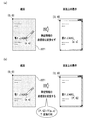
- FIG. 2 and FIG. 3 are diagrams for explaining misalignment or orientation error that should be corrected according to the present embodiment.
- the student has just written “ ⁇ ABC” using the electronic pen 2 in the “answer 1” column of the form 3 (FIG. 2A).
- the teacher visually recognizes what the student wrote on the paper on the screen (FIG. 2B).
- “ ⁇ ABC” 211 is displayed on the right side of the “answer 1” column on the screen.
- “ ⁇ ABC” 211 is displayed. In this case, since “ ⁇ ABC” 211 is an answer to be entered in the column, no particular problem occurs.
- FIG. 3A Even though the student entered “ ⁇ ABC” in the “answer 1” field on the form 3, the screen may appear as if “ ⁇ ABC” 212 was entered in the “answer 2” field.
- FIG. 3B “ ⁇ ABC” 213 may be displayed upside down at a position that is completely unrelated (FIG. 3B).
- the misalignment in FIG. 3A is caused by misalignment when the dot pattern printed paper 3 is set in the printer (details will be described later).
- the orientation error (upside down) in FIG. 3B is caused by the fact that the dot pattern printed paper 3 is set in the wrong orientation with respect to the printer (details will be described later).
- FIG. 4 is a diagram illustrating the configuration of the calibration apparatus 1 and the like.
- the calibration device 1 is connected to the writing information communication device 5 and the reference terminal device 6 via the network 4.
- the one or more electronic pens 2 transmit writing information to the writing information communication device 5 using wireless communication technology.
- the calibration device 1 and the writing information communication device 5 may be directly connected without going through the network 4.
- the calibration apparatus 1 is a general computer, and is managed by an educational company.
- the calibration device 1 includes a central control device (control unit) 11, an input device 12 such as a keyboard and a mouse, an output device 13 such as a display, a screen, and a printer, a main storage device 14, an auxiliary storage device 15, and a communication device 16. . These are connected to each other by a bus.
- the calibration apparatus 1 is usually installed in a classroom.
- the writing information entered by the student with the electronic pen 2 is displayed on the screen of the output device 13, and the teacher gives guidance to the student while visually checking the screen.
- the list unit 34 is a program. Thereafter, when the subject is described as “XX section”, the central control device 11 reads each program from the auxiliary storage device 15 and loads it into the main storage device 14, and then the function of each program (detailed later). Shall be realized.
- the auxiliary storage device 15 stores a learning material database 41, a writing information database 42 and a class information database 43.
- the writing information communication device 5 receives the writing information from the electronic pen 2 and transmits the writing information to the calibration device 1 in a predetermined cycle after sequentially or temporarily storing the writing information.
- One writing information communication device 5 is installed in each classroom where the electronic pen 2 is used, for example.
- the reference terminal device 6 is a general computer, and its configuration (other than the program and the database) conforms to the calibration device 1.
- the reference terminal device 6 is usually arranged in a staff room or the like, and handwriting information or the like is displayed on the output device.
- FIG. 5 (a) is a diagram for explaining the function and information flow of each program and clarifying the problem.
- the worksheet file creation unit 21 is a general document creation application.
- the worksheet file creation unit 21 creates a problem (by being operated by the teacher).
- the problem is intangible electronic data unless printed on paper by a printer. This problem is called “worksheet electronic file”.
- the dot pattern image file generation unit 22 generates a dot pattern.
- the dot pattern is also intangible electronic data unless it is printed on paper by a printer. This dot pattern is called a “dot pattern electronic file”.
- the worksheet image synthesis unit 23 synthesizes the worksheet electronic file and the dot pattern electronic file. What is synthesized is an intangible “worksheet image electronic file with dot pattern”.
- the dot pattern worksheet printing unit 24 receives the dot pattern worksheet image electronic file and prints it on a sheet.
- the printed product is a tangible “worksheet with dot pattern”.
- intangible data is represented by a thick broken line
- tangible paper or the like is represented by a thick solid line (the same applies to the following drawings).
- Fig. 5 (b) is another diagram for explaining the function and information flow of each program and clarifying the problem.
- the worksheet file creation unit 21 creates a worksheet electronic file, as in FIG.
- the dot pattern image file generation unit 22 also generates a dot pattern electronic file.
- the dot pattern printing unit 25 receives the dot pattern electronic file and prints it on the paper.
- the printed product is “dot pattern printed paper”.
- the worksheet image superimposing printing unit 26 receives the worksheet electronic file and prints it on the paper with the dot pattern printed.
- the printed product is a “worksheet with a dot pattern”.
- FIG. 5A and 5B are compared.
- the dot pattern electronic file and the worksheet electronic file are synthesized by the worksheet image synthesis unit 23.
- the origin of the coordinate system of the worksheet electronic file coincides with the origin of the coordinate system of the dot pattern electronic file. That is, the calibration apparatus 1 considers them the same.
- a dot pattern, a problem, and the like are simultaneously printed on a normal sheet without a dot pattern set in a printer (loaded on a tray). Therefore, problems such as the above-described misalignment and orientation error do not occur.
- FIG. 5B the process of printing a dot pattern on a normal sheet and the process of printing a worksheet electronic file (problem etc.) on a dot pattern printed sheet are separated.
- a worksheet with a dot pattern can be printed according to the flow of FIG.
- the dot pattern image file generation unit 22 itself is often an application that requires a license. If the dot pattern image file generation unit 22 is not prepared by itself, the dot pattern worksheet must be printed in the flow of FIG. 5B. In other words, in FIG. 5B, the processing of the dot pattern image file generation unit 22 and the dot pattern printing unit 25 is performed by the printer, etc., and the school purchases the dot pattern printed paper from the printer, etc. Will be processed. Then, problems such as the above-described misalignment and orientation error occur.
- FIG. 6 is a diagram illustrating the function of each program and the flow of information, and an outline of countermeasures against misalignment.
- the dot pattern image file generation unit 22 generates a dot pattern electronic file with dot markers.
- the “dot marker” is a mark such as “+” indicating the positions of the four corners of the dot pattern (details will be described later).
- the coordinate value of the dot marker is a coordinate value of the coordinate system of the dot pattern. This coordinate system and coordinate values are referred to as “dot pattern coordinate system” and “dot pattern coordinate value”.
- the dot pattern printing unit 25 receives the dot marker electronic file with dot markers and prints it on the paper.
- the printed product is “dot pattern printed paper”.
- a dot marker is printed on the dot pattern printed paper together with the dot pattern.
- the worksheet file creation unit 21 is the same as in FIG.
- the calibration marker image file generation unit 27 generates a calibration marker image file.
- the “calibration marker” is a mark such as “ ⁇ ” indicating the positions of the four corners of the worksheet electronic file (details will be described later).
- the worksheet file image synthesis unit 28 receives the worksheet electronic file and the calibration marker image file, synthesizes them, and creates a worksheet electronic file with a calibration marker.
- the worksheet electronic file is, of course, a set of pixel values indicating characters, figures, etc., associated with the coordinate values.
- the worksheet electronic file is also commonly referred to as “content”.
- the coordinate value of the pixel value is a coordinate value of the coordinate system of the worksheet electronic file. This coordinate system and coordinate values are referred to as “content coordinate system” and “content coordinate value”.
- the calibration marker also has content coordinate values.
- the worksheet image superposition printing unit 26 receives the calibration marker-added worksheet electronic file and prints it on the dot pattern printed paper.
- the printed product is a worksheet with a dot pattern. At this stage, the calibration marker is printed on the worksheet with the dot pattern together with the problem and the dot marker is also printed.
- the electronic pen 2 can acquire the coordinate value of the dot marker. This coordinate value is a dot pattern coordinate value.
- the marker coordinate input unit 29 acquires the dot pattern coordinate value of the dot marker via the electronic pen 2. Further, the marker coordinate input unit 29 acquires the content coordinate value of the calibration marker.
- the coordinate conversion coefficient calculation unit 30 acquires at least three combinations of the content coordinate value of the calibration marker and the corresponding dot pattern coordinate value of the dot marker. Now, a “conversion matrix” for converting dot pattern coordinate values into content coordinate values is assumed.
- the conversion matrix has a plurality of components (conversion coefficients). Since the content coordinate value and the dot pattern coordinate value of the combination are known, the coordinate conversion coefficient calculation unit 30 can determine a specific value of the conversion coefficient by solving the simultaneous equations (details will be described later). .
- the calibration device 1 converts the dot pattern coordinate value of the writing information acquired via the electronic pen 2 into the content coordinate value using the conversion matrix including the determined conversion coefficient. Then, the worksheet electronic file and the writing information are superimposed and displayed on the output device 13.
- FIG. 7 is a diagram for explaining the function of each program and the flow of information, and showing an outline of countermeasures against misdirection.
- the worksheet file creation unit 21, the dot pattern image file generation unit 22, the dot pattern printing unit 25, and the worksheet image superimposed printing unit 26 are the same as those in FIG.
- the writing information input unit 31 receives writing information from the electronic pen 2.
- the writing direction estimation unit 32 estimates the writing information rotation angle based on the writing information.
- the writing information rotation angle indicates how many times the paper has been rotated and set on the basis of the correct angle (0 degree) at which the writing information erects on the screen.
- the writing information rotation unit 33 receives the writing information rotation angle and converts the coordinate value of the writing information so as to cancel the writing information rotation angle. For example, when the rotation angle of the writing information is 90 degrees, the coordinate value of the writing information is converted into a coordinate value rotated 90 counterclockwise around the center of the sheet (intersection of diagonal lines).
- FIG. 8 is a diagram illustrating an example of the teaching material database 41.
- the learning material database 41 includes a guide 41a and learning material information 41b.
- the school year column 102 in association with the learning material ID stored in the learning material ID column 101, the school year column 102 includes the grade, the subject column 103 includes the subject, the unit column 104 includes the unit, and the teaching material information pointer column 105.
- the learning material ID in the learning material ID column 101 is an identifier that uniquely identifies the combination of the grade, the subject, and the unit.
- the grade in the grade column 102 is the grade of a class in which classes are performed using the electronic pen 2.
- the subject in the subject column 103 is a subject name of a class conducted using the electronic pen 2.
- the unit in the unit column 104 is a further subdivision of the subject and is the theme of the lesson.
- the pointer to the learning material information in the learning material information pointer column 105 is information indicating the location of the learning material information related to the “worksheet with dot pattern” among the plurality of learning material information 41b. There are as many records of the guide 41a as there are “combinations of grade, subject and unit”.
- the teacher / student flag column 112 in association with the page number stored in the page number column 111, has the teacher / student flag, the dot pattern ID column 113 has the dot pattern ID, and the worksheet electronic file.
- the name column 114 stores a worksheet electronic file name.
- the page number in the page number column 111 is the page number of each page of the teaching material.
- the teacher / student flag in the teacher / student flag column 112 is a symbol indicating a person who can enter characters or the like on the page using the electronic pen 2. “T” indicates that the teacher can fill in, and “S” indicates that the student can fill in. If both can fill in, two records are created for the page.
- the dot pattern ID in the dot pattern ID column 113 is an identifier that uniquely identifies the dot pattern.
- the page number and the dot pattern ID have a one-to-one correspondence.
- the worksheet electronic file name in the worksheet electronic file name column 114 is a name for each page of the worksheet electronic file. There is a one-to-one correspondence between page numbers and worksheet electronic file names. It is assumed that the worksheet electronic file 115 itself is also stored in the teaching material database 41. There are as many educational material information 41b as there are educational material IDs.
- Writing information database In the writing information database 42, writing information (FIG. 1B) is stored.
- FIG. 9 is a diagram illustrating an example of the class information database 43.
- the class information database 43 includes a guide 43a and class information 43b.
- the grade column 122 in association with the class ID stored in the class ID column 121, the grade column 122 has the grade, the class name column 123 has the class name, the teacher name column 124 has the teacher name, A pointer to class information is stored in the information pointer column 125.
- the class ID in the class ID column 121 is an identifier that uniquely identifies the class.
- the grade in the grade column 122 is the same as the grade in FIG.
- the class name in the class name column 123 is a name of a class belonging to the school year.
- the teacher name in charge teacher name column 124 is the name of the teacher in charge of the class.
- the pointer to the class information in the class information pointer column 125 is information indicating the location of the class information related to the class among the plurality of class information 43b. There are as many records of the guide 43a as the number of class IDs.
- the pen ID column 132 stores the pen ID
- the student name column 133 stores the student name.
- the attendance number in the attendance number column 131 is the order in which the teacher calls the students to check attendance in the class, and in many cases, the attendance numbers are numbers in which the student names are arranged in alphabetical order.
- the pen ID in the pen ID column 132 is an identifier that uniquely identifies the electronic pen 2.
- the student name in the student name column 133 is the name of the student.
- FIG. 10 is a diagram illustrating another example of the class information database 43.
- the class information database 43 in FIG. 10 is a modification of the class information database 43 in FIG. In FIG. 9, it is assumed that each student uses a different electronic pen 2. In FIG. 10, it is assumed that there are as many electronic pens 2 as there are students in one class (for example, 40), and that 40 electronic pens 2 are reused in all classes.
- the class information database 43 in FIG. 10 includes guides 43c, pen information 43d, and student information 43e. Compared with the guide 43a in FIG. 9, the guide 43c in FIG. 10 has a pointer field 145 to pen information and a pointer field 146 to student information instead of the pointer field 125 to class information.
- the pointer to the pen information stored in the pen information pointer column 144 is information indicating the location of the pen information 43d.
- the pointer to the student information stored in the student information pointer field 146 is information indicating the location of the student information related to the class among the plurality of student information 43e. Since other configurations are the same as those in FIG. 9, detailed description of each of the columns 141 to 144 is omitted.
- the pen information 43d has a configuration in which the student name column 133 is deleted from the class information 43b (FIG. 9). Therefore, detailed description of each column 161, 162 is omitted. However, there is only one pen information 43d regardless of the number of classes.
- the student information 43e has a configuration in which the pen ID column 132 is deleted from the class information 43b (FIG. 9). Therefore, detailed description of each column 171 and 172 is omitted. However, there are as many pen information 43d as the number of class IDs.
- FIG. 11 is a diagram for explaining the relationship between the dot pattern coordinate system and the content coordinate system.
- FIG. 11A shows a worksheet 221 (paper surface) with a dot pattern distributed to students. The origin of the dot pattern coordinate system is at the upper left point (0, 0) of the dot pattern worksheet 221.
- a character string “problem”, a rectangular parallelepiped, a cylindrical figure, and the like that are printed in a portion surrounded by a broken line on the upper and left sides of the worksheet 221 with a dot pattern are portions derived from the worksheet electronic file. These character strings, graphics, and the like are referred to as “content-derived data”.
- the content-derived data has content coordinate values in the content coordinate system.
- the origin of the content coordinate system is a point corresponding to the point 222 where two broken lines contact.
- the coordinate value of the point 222 read by the electronic pen 2 is not (0, 0).
- the electronic pen 2 reads the dot pattern coordinate value (s, t) from the point 222 (where s ⁇ 0 and t ⁇ 0).
- “ ⁇ ABC” 223 is the handwriting of the student.
- the electronic pen 2 reads the dot pattern coordinate value (p, q) from a certain point “ ⁇ ABC” 223.
- FIG. 11B shows a display on the screen of the output device 13.
- the worksheet electronic file 224 has a content coordinate system, and its origin is a point 225 [0, 0].
- the content-derived data is displayed at a position indicated by its own content coordinate value.
- the calibration device 1 recognizes the dot pattern coordinate value of the student handwriting 223 read by the electronic pen 2 as the content coordinate value in the content coordinate system (in the first place, the dot pattern coordinate value and the content coordinate value are distinguished from each other).
- the student's handwriting “CABC” 226 is displayed slightly shifted from the right side of the original position “Answer 1” to the lower right.
- the calibration apparatus 1 applies the dot pattern coordinate values (p, q) “p” and “q” to the content coordinate system without conversion. This is expressed as [p, q] in FIG. 11B and FIG. 12A described later. Lowercase letters such as p and q are dot pattern coordinate values, and uppercase letters such as P and Q are content coordinate values. (,) Indicates that the calibration apparatus 1 recognizes that the value in it is a dot pattern coordinate value. [,] Indicates that the calibration apparatus 1 recognizes that the value therein is the content coordinate value. It is necessary to convert the dot pattern coordinate value into the content coordinate value by some method.
- FIG. 12 is a diagram for explaining the conversion of coordinate values.
- the dot pattern coordinate value of the writing information is not converted to the content coordinate value. Therefore, the position where “ ⁇ ABC” is displayed is shifted.
- the dot pattern coordinate value of the writing information is converted to the content coordinate value. Therefore, “ ⁇ ABC” is displayed at the correct position.
- the conversion matrix (T) converts p into P and q into Q.
- FIG. 13 is a diagram for explaining the transformation matrix.
- a transformation matrix (T) 232 shown in FIG. 13A is a square matrix of 3 rows ⁇ 3 columns. Of the nine components included in the transformation matrix 232, six in the first and second rows are transformation coefficients. Now, three sets of dot pattern coordinate values (x 1 , y 1 ), (x 2 , y 2 ), and (x 3 , y 3 ), and three sets of content coordinate values (X 1 , Y 3 ) corresponding to them. 1 ), (X 2 , Y 2 ) and (X 3 , Y 3 ) are given. Then, as is clear from FIG.
- FIG. 13A by solving the six simultaneous equations in the dashed rectangle, the six transformation coefficients (a, b, c, d, e) which are the solutions (unknown numbers) are obtained. And f) can be determined.
- FIG. 13B is a diagram illustrating the function of the transformation matrix in an intuitive manner.
- FIG. 14 is a diagram for explaining the association between the dot marker and the calibration marker.
- the worksheet electronic file 234 (with calibration markers) is obtained by attaching calibration markers 235a, 235b, 235c, and 235d to the four corners of the worksheet electronic file 233.
- the dot pattern printed paper 237 is obtained by printing the dot pattern printed paper 236 together with the dot markers 238a, 238b, 238c, and 238d at the four corners.
- a dot pattern worksheet 239 is obtained by printing the worksheet electronic file 234 on the dot pattern printed paper 237.
- Position alignment processing procedure 15 and 16 are flowcharts of the position alignment processing procedure.
- the position alignment processing procedure corresponds to FIG. It is assumed that the class information data pace 43 (FIGS. 9 and 10) has already been completed at the start of the position alignment processing procedure.
- the worksheet file creation unit 21 creates a worksheet electronic file. Specifically, the worksheet file creation unit 21 accepts that a user (teacher) creates a worksheet electronic file including a question sentence, a figure, and the like via the input device 12. The worksheet electronic file is created so that one page of a problem or the like to be distributed becomes one worksheet electronic file. When the user creates a worksheet electronic file that spans multiple pages, the worksheet file creation unit 21 may divide it into pages. Furthermore, the worksheet file creation unit 21 accepts that the user inputs a worksheet electronic file name for each page.
- step S ⁇ b> 302 the worksheet file creation unit 21 creates the teaching material database 41. Specifically, first, the worksheet file creation unit 21 sets a new record of the teaching material information 41b in the teaching material database 41 (FIG. 8) as the number of worksheet electronic files (number of pages) created in step S301. ) And store the page numbers as 1, 2, 3,... In the page number column 111 of the new record. Second, the worksheet file creation unit 21 stores the worksheet electronic file name received in step S301 in the worksheet electronic file name column 114 of the new record.
- the worksheet file creation unit 21 accepts that the user designates a teacher / student flag for each page, and stores the accepted teacher / student flag in the teacher / student flag column 112 of the new record.
- the record on the page is copied into two, and “T” and “S” are stored in the teacher / student flag column 112 of each record.
- the worksheet file creation unit 21 stores the dot pattern ID in the dot pattern ID column 113 of the new record.
- the worksheet file creation unit 21 stores a dot pattern ID related to an unused dot pattern for each page number.
- the worksheet file creation unit 21 creates a new record of the guide 41a of the teaching material database 41 (FIG. 8).
- the worksheet file creation unit 21 accepts that a user inputs a school year, a subject, and a unit via the input device 12.
- the worksheet file preparation part 21 memorize
- the learning material ID is numbered and stored in the learning material ID column 101.
- the worksheet file creation unit 21 stores the pointer to the learning material information in the pointer column 105 to the learning material information of the new record.
- step S303 the calibration marker image file generation unit 27 generates a calibration marker image file.
- step S304 the worksheet file image composition unit 28 creates a worksheet electronic file with calibration markers. Specifically, the worksheet file image synthesis unit 28 synthesizes the worksheet electronic file created in step S301 and the calibration marker image file generated in step S303, and the calibration marker-added worksheet electronic Create a file.
- step S305 the dot pattern image file generation unit 22 generates a dot pattern electronic file with dot markers. At this time, the dot pattern image file generation unit 22 numbers the dot pattern ID of the generated dot pattern.
- the dot pattern printing unit 25 creates a dot pattern printed paper. Specifically, the dot pattern printing unit 25 prints the dot pattern and the dot pattern ID on the paper (paper in a blank state without the dot pattern) via the output device 13. The number of printed sheets (usually the number of students) is specified by the user (teacher). It is assumed that the dot pattern ID is printed on an inconspicuous portion of the paper sufficiently small to be visible with the naked eye.
- the worksheet image superposition printing unit 26 creates a worksheet with a dot pattern. Specifically, first, the worksheet image superposition printing unit 26 accepts that a user (teacher) selects a worksheet electronic file name via the input device 12. For example, the worksheet image superposition printing unit 26 displays the guide 41a of the teaching material database 41 (FIG. 8) on the screen of the output device 13, and accepts that the user selects an arbitrary record. Then, using the pointer to the learning material of the selected record as a search key, the corresponding learning material information 41b is acquired, the acquired learning material information 41b is displayed, and it is accepted that the user selects an arbitrary record.
- the worksheet image overlay printing unit 26 acquires the worksheet electronic file name and the dot pattern ID of the record of the selected teaching material information 41b. Third, the worksheet image overlay printing unit 26 prints the worksheet electronic file having the acquired worksheet electronic file name on the dot pattern printed paper having the acquired dot pattern ID and equal to the number of students. .
- step S308 the electronic pen 2 accepts a tap on the dot marker (places the pen tip on the dot marker). Specifically, the electronic pen 2 accepts that the user (teacher) uses the electronic pen 2 to tap any one of the dot markers at the four corners of the printed dot pattern-added worksheet. . Then, the electronic pen 2 reads the dot pattern coordinate value of the dot marker.
- the marker coordinate input unit 29 acquires the coordinate value of the dot marker. Specifically, the marker coordinate input unit 29 receives the dot pattern coordinate value of the dot marker from the electronic pen 2. In step S310, the marker coordinate input unit 29 displays the tap position on the screen. Specifically, the marker coordinate input unit 29 displays the received dot pattern coordinate value on the screen of the output device 13. At this time, the marker coordinate input unit 29 displays the tapped position within the frame of the worksheet with the dot pattern with a conspicuous symbol such as “ ⁇ ”.
- step S311 the marker coordinate input unit 29 displays a confirmation message. Specifically, the marker coordinate input unit 29 reads, “Are you tapping this way? If so, press the“ F1 ”key, otherwise press the“ F2 ”key.” Message is displayed on the screen of the output device 13.
- step S312 the marker coordinate input unit 29 determines whether confirmation has been made. Specifically, in the above example, if the marker coordinate input unit 29 determines that the user has pressed the “F1” key (step S312 “YES”), the process proceeds to step S313, and the user presses the “F2” key. If it is determined that the button is pressed (“NO” in step S312), the process returns to step S308.
- step S313 the marker coordinate input unit 29 stores the coordinate value. Specifically, the marker coordinate input unit 29 temporarily stores the dot pattern coordinate value received in step S ⁇ b> 309 in the main storage device 14.
- step S314 the marker coordinate input unit 29 determines whether or not three coordinate values are stored. Specifically, if the number of dot pattern coordinate values temporarily stored in the main storage device 14 has reached 3 (step S314 “YES”), the marker coordinate input unit 29 proceeds to step S315, In other cases (step S314 “NO”), the process returns to step S308.
- the marker coordinate input unit 29 may execute the following processing. Calculate an equation of a straight line that passes through the dot pattern coordinate value acquired for the first time and the dot pattern coordinate value acquired for the second time. -It is determined whether the dot pattern coordinate value acquired for the third time satisfies the equation. If not satisfied, the process proceeds to step S310. If satisfied, a message “Please tap again” is displayed, and the process returns to step S308. As long as the user consciously taps the dot markers at the four corners, these processes are unnecessary. However, for example, when the user's hand shakes and the tap is repeated twice within a short period, these processes are effective.
- step S315 the marker coordinate input unit 29 acquires the content coordinate value of the calibration marker. Specifically, first, the marker coordinate input unit 29 acquires three content coordinate values respectively corresponding to the three dot pattern coordinate values stored in step S313. Now, it is assumed that the stored coordinate values are (x 1 , y 1 ), (x 2 , y 2 ) and (x 3 , y 3 ). Hereinafter, in step S308, the description will be continued with an example in which the user taps in the order of the upper left dot marker ⁇ the upper right dot marker ⁇ the lower left dot marker.
- the marker coordinate input unit 29 acquires content coordinate values in the order of the upper left calibration marker ⁇ the upper right calibration marker ⁇ the lower left calibration marker from the content coordinate values of the four calibration markers. . It is assumed that the acquired coordinate values are [X 1 , Y 1 ], [X 2 , Y 2 ] and [X 3 , Y 3 ].
- step S316 the coordinate conversion coefficient calculation unit 30 calculates a conversion coefficient. Specifically, known values (x 1 , y 1 ), (x 2 , y 2 ) and (x 3 , y 3 ), and [X 1 , Y 1 ], [X 2 , Y 2] and [X 3, Y 3] is substituted into the six simultaneous equations (dashed in rectangular FIG. 13 (a)), by solving the simultaneous equations, transform coefficient is unknown a, b, c, Find d, e and f.
- the coordinate conversion coefficient calculation unit 30 may use any known method.
- step S317 the worksheet image superposition printing unit 26 matches the coordinate values. Specifically, first, the worksheet image superimposition printing unit 26 uses the conversion matrix having the conversion coefficient acquired in step S316 as a component, and the coordinate value 204 of the writing information acquired by the electronic pen 2 (see FIG. 1 (b)) is converted into content coordinate values.
- step S318 the worksheet image overlay printing unit 26 displays the writing information. Specifically, the worksheet image superimposition printing unit 26 displays the content coordinate value (derived from the electronic pen 2) converted in step S317 on the screen of the output device 13 with the content-derived data superimposed. At this time, the positional deviation of the writing information is eliminated. Thereafter, the position alignment processing procedure ends.
- FIG. 17 is a diagram illustrating a method of displaying a plurality of printed dot pattern worksheets on the same screen.
- the educational material information 41b includes records relating to the page (one page) 241 and the page (two pages) 242 of FIG. Since the pages are different, the dot pattern printed on the paper surface (one page) 241 and the dot pattern printed on the paper surface (two pages) 242 are different. Processing for displaying these papers side by side on the screen of the output device 13 will be described below.
- the simultaneous list unit 34 accepts that the user selects two records for pages that the user desires to display side by side from the learning material information 41b. (2) The simultaneous list unit 34 acquires the worksheet electronic file 115 of the selected record. (3) The simultaneous list unit 34 acquires the dot pattern ID of the selected record. (4) The simultaneous list section 34 prints two worksheets with dot patterns by printing a dot pattern with a corresponding dot pattern ID on the acquired worksheet electronic file. On each worksheet with a dot pattern, dot markers (“+” in the figure) are printed at the four corners.
- the simultaneous list unit 34 accepts that the user taps the dot marker on the page (page 1) 241 and the dot marker on the page (page 2) 242 using the electronic pen 2 in a predetermined order.
- the predetermined order is, for example, upper left ⁇ upper right ⁇ lower left ⁇ lower right for the first page, and then upper left ⁇ upper right ⁇ lower left ⁇ lower right for the second page. In FIG. 17, this order is written in “ ⁇ ”.
- the simultaneous list unit 34 acquires a difference obtained by subtracting the coordinate value of the upper left calibration marker from the coordinate value of the upper right calibration marker of the worksheet electronic file. (7) The simultaneous list unit 34 adds the difference acquired in (6) to the x coordinate values of all characters, figures, etc. in the worksheet electronic file on the second page. (8) The simultaneous list unit 34 acquires a difference obtained by subtracting the x coordinate value of the upper left dot marker from the x coordinate value of the upper right dot marker. (9) The simultaneous list unit 34 adds the difference acquired in (8) to the x coordinate values of all the handwriting information acquired by the electronic pen 2 from the page (2 pages) 242.
- the simultaneous list unit 34 considers all the content coordinate values of the first and second pages as the content coordinate values of the first page, and outputs the worksheet electronic files of the first and second pages. 13 screens.
- the simultaneous list unit 34 considers all the dot pattern coordinate values of the first and second pages as the dot pattern coordinate values of the first page, and outputs writing information of the first and second pages. It is displayed on the screen of the device 13.
- the screen of the output device 13 becomes a screen 243 in FIG. That is, the upper right of the first page and the upper left of the second page overlap, and the lower right of the first page overlaps with the lower left of the second page, and two pages are displayed side by side.
- FIG. 17 there are cases where there are “3 pages” and after. However, the description thereof is the same as described above, and will be omitted.
- FIG. 18 is a diagram for explaining a method of displaying the front and back surfaces of the printed worksheet with a dot pattern on the same screen.
- the processing of the simultaneous list unit 34 in this case is the same as the above (1) to (11).
- “first page” or “first page” is read as “front side”
- “second page” or “second page” is called “back side”. Replace it.
- “print two dot pattern worksheets” is read as “two dot pattern worksheets are printed on both sides of one sheet”.
- FIG. 19 is a diagram for explaining another method for displaying a plurality of pages of a printed worksheet with a dot pattern on the same screen.
- the paper surface (2 pages) 244 is in the landscape orientation.
- the processing of the simultaneous list unit 34 in this case is as follows (12) to (20).
- the simultaneous list unit 34 performs the processes (1) to (4). (13) The simultaneous list unit 34 accepts that the user taps the dot marker on the paper surface (1 page) 241 and the dot marker on the paper surface (2 pages) 244 using the electronic pen 2 in a predetermined order.
- the predetermined order is, for example, upper left ⁇ upper right ⁇ lower left ⁇ lower right for the first page, and then lower left ⁇ upper left ⁇ lower right ⁇ upper right for the second page (based on the vertical position). In FIG. 19, this order is written in “ ⁇ ”.
- the simultaneous list unit 34 acquires the difference 1 obtained by subtracting the x coordinate value of the upper left calibration marker from the x coordinate value of the upper right calibration marker in the worksheet electronic file. Further, a difference 2 is obtained by subtracting the y coordinate value of the upper left calibration marker from the y coordinate value of the lower left calibration marker. Then, the value of (difference 2 ⁇ difference 1 ) / 2 is calculated. (15) The simultaneous list unit 34 converts the coordinate values of all characters, figures, etc. in the worksheet electronic file on the second page into coordinate values rotated 90 degrees clockwise around the origin. (16) The simultaneous list unit 34 adds the difference 1 acquired in (14) to the x coordinate values of all characters, figures, etc. in the worksheet electronic file on the second page. Further, (difference 2 ⁇ difference 1 ) / 2 acquired in (14) is added to the y coordinate value.
- the simultaneous list unit 34 obtains a difference 3 obtained by subtracting the x coordinate value of the upper left dot marker from the x coordinate value of the upper right dot marker. Further, a difference 4 is obtained by subtracting the y coordinate value of the upper left dot marker from the y coordinate value of the lower left dot marker. Then, the value of (difference 4 ⁇ difference 3 ) / 2 is calculated. (18) The simultaneous list unit 34 converts the coordinate values of all the writing information acquired by the electronic pen 2 from the page (page 2) 244 into coordinate values rotated 90 degrees clockwise around the origin. (19) The simultaneous list unit 34 adds the difference 3 acquired in (17) to the x coordinate values of all the writing information acquired by the electronic pen 2 from the page (page 2) 244. Further, the value of (difference 4 ⁇ difference 3 ) / 2 acquired in (17) is added to the y coordinate value. (20) The simultaneous list unit 34 performs the processes (10) to (11).
- the screen of the output device 13 becomes a screen 245 of FIG. That is, the second page is rotated 90 degrees clockwise, and the middle point between the upper right and lower right of the first page and the middle of the second page (based on the vertical position) between the lower left and lower right.
- the dots overlap and two pages are displayed side by side.
- “page 1” and “page 2” may be “front surface” and “back surface”, respectively. However, the description thereof is the same as described above, and will be omitted.
- FIG. 20 is a diagram illustrating a method for displaying writing information of a plurality of electronic pens 2 on the same screen.
- the processing of the simultaneous list unit 34 for displaying such a screen is as follows (21) to (31).
- the simultaneous list unit 34 receives writing information from the six electronic pens 2.
- the simultaneous list unit 34 refers to the class information 43b (or pen information 43d) and acquires an attendance number corresponding to the pen ID of the writing information.
- h 1 is a value obtained by subtracting the x coordinate value of the upper left dot marker from the x coordinate value of the upper right dot marker (the horizontal width of the paper surface).
- h 2 is any positive number indicating the horizontal length of the gap between the sheets.
- v 1 is a value obtained by subtracting the y coordinate value of the upper left dot marker from the y coordinate value of the lower left dot marker (the height of the paper surface).
- v 2 is any positive number indicating the vertical length of the gap between the sheets.
- the simultaneous list unit 34 displays all writing information and all worksheet electronic files on the screen of the output device 13.
- the screen of the output device 13 becomes a screen 246 in FIG.
- 21 and 22 are diagrams for explaining a method of displaying only the selected portion.
- a student is provided with a worksheet (paper surface) 251 with a dot pattern on which a question or the like is printed.
- the lower half of the page is an answer field, and teachers want to see only this answer field on the screen for all students. Processing of the simultaneous list unit 34 for displaying such a screen is as follows (32) to (40).
- the simultaneous list unit 34 accepts that the user (teacher) specifies a range to be displayed on the screen on the dot pattern worksheet. For example, when the user wants to display a range surrounded by a broken line in FIG. 22 on the screen, the user taps the four corners (indicated by ⁇ ) with the electronic pen 2.
- the simultaneous list unit 34 acquires the coordinate values of the four corners from the electronic pen 2.
- the acquired coordinate values are (5, 60) for the upper left, (75, 60) for the upper right, (5, 110) for the lower left, and (75, 110) for the lower right.
- FIG. 23 is a diagram for explaining orientation correction in a rectangular sheet.
- the paper when the paper is “rectangular”, it means “rectangular” other than “square”.
- the Japanese writing information is displayed on the screen as indicated by reference numeral R01 or R03.
- a language written from right to left, such as Arabic, is displayed on the screen as indicated by reference numeral R05.
- the dot pattern printed paper is set upside down, the writing information to be displayed as indicated by the symbol R01 is displayed as indicated by the symbol R02.
- the writing information to be displayed as indicated by reference numeral R03 is displayed as indicated by reference numeral R04
- the writing information to be displayed as indicated by reference numeral R05 is displayed as indicated by reference numeral R06.
- “ ⁇ ” is the order in which the user (student) writes. Since the writing information has the current time (FIG. 1B), the calibration apparatus 1 can identify the order.
- FIG. 24 is a diagram for explaining orientation correction on a square sheet.
- Symbols Q01, Q05, and Q09 in FIG. 24 correspond to symbols R01, R03, and R05 in FIG. 23, respectively (which should originally be displayed in this way).
- the symbols Q03, Q07, and Q11 in FIG. 24 correspond to the symbols R02, R04, and R06 in FIG. 23 (reversed upside down).
- the writing information of reference signs Q02, Q06, and Q10 is displayed rotated 90 degrees clockwise with reference to the writing information of reference signs Q01, Q05, and Q09.
- the writing information of reference signs Q04, Q08, and Q12 is displayed rotated 270 degrees clockwise with reference to the writing information of reference signs Q01, Q05, and Q09.
- the square dot pattern printed paper has a large number of orientation error variations compared to the rectangular dot pattern printed paper because there is no distinction between vertical and horizontal directions.
- FIG. 25 is a diagram for explaining terms and basic concepts in the orientation correction processing procedure.
- FIG. 25 (a) is hiragana “ni”.
- Ni is a character consisting of three strokes.
- a group of images connected by black pixels is called a “connected component” 261.
- the vertical first image, the horizontal second image, and the horizontal third image are separate connected components.
- “Kusakanmuri” is one connected component.
- a rectangle circumscribing the connected component is referred to as a “circumscribed rectangle” 262.
- “Ni” has three circumscribed rectangles. Some circumscribed rectangles belonging to the same character may overlap.
- One or a plurality of circumscribed rectangles located within a predetermined distance range are grouped.
- the calibration apparatus 1 recognizes this group as a character.
- a rectangle circumscribing all circumscribed rectangles included in a character is referred to as “integrated circumscribed rectangle” 263 (FIG. 25B).
- FIG. 25 (c) shows a state in which the student has written “Michiko Fujiwara makes Emperor Akiko Go Ichijo enter the daughter” in horizontal writing using the electronic pen 2 on the worksheet with the dot pattern. 264).
- 25 (d) and 25 (e) are enlarged views of the first two characters (reference numerals 265 to 268). Now, consider comparing the coordinate values of the center points (intersections of diagonal lines) of two adjacent integrated circumscribed rectangles. “ ⁇ x” indicates how much the x coordinate value of the central point of a certain integrated circumscribed rectangle has increased (rightward in the positive direction) compared to the x coordinate value of the central point of the previous integrated circumscribed rectangle. is there.
- ⁇ y In the case of horizontal writing from left to right (FIG. 25 (d)), ⁇ x is generally larger than ⁇ y. On the other hand, in the case of vertical writing from top to bottom (FIG. 25E), ⁇ y is generally larger than ⁇ x.
- FIG. 26 is a flowchart of the orientation correction processing procedure for rectangular paper. As a premise for starting the processing procedure, it is assumed that the electronic pen 2 reads writing information from a single worksheet with a dot pattern, and the writing information is stored in the writing information database 42.
- step S341 the writing direction estimation unit 32 extracts a connected component. Specifically, the writing direction estimation unit 32 reproduces the handwriting entered by the user (student) based on the coordinate value and the pixel value included in the writing information. A plurality of connected components are extracted from the handwriting by a known method.
- step S342 the writing direction estimation unit 32 generates a circumscribed rectangle. Specifically, the writing direction estimation unit 32 generates a circumscribed rectangle for all extracted connected components by a known method.
- step S343 the writing direction estimation unit 32 generates an integrated circumscribed rectangle. Specifically, first, the writing direction estimation unit 32 groups all generated circumscribed rectangles within a predetermined distance range. Secondly, the writing direction estimation unit 32 generates an integrated circumscribed rectangle by a known method for all circumscribed rectangles (corresponding to characters) belonging to each group.
- step S344 the writing direction estimation unit 32 acquires the number (N) of integrated circumscribed rectangles.
- step S345 the writing direction estimation unit 32 sets variables “AvrX” and “AvrY”, and substitutes “0” for each.
- step S346 the writing direction estimation unit 32 sets a variable “i” and substitutes 2 for “i”.
- step S347 the writing direction estimation unit 32 calculates ⁇ x. Specifically, the writing direction estimation unit 32 acquires the x coordinate value of the center point of the i-th integrated circumscribed rectangle and the x coordinate value of the center point of the (i ⁇ 1) -th integrated circumscribed rectangle, and the former A value obtained by subtracting the latter from is assumed to be ⁇ x.
- step S348 the writing direction estimation unit 32 calculates ⁇ y. Specifically, the writing direction estimation unit 32 acquires the y coordinate value of the center point of the i-th integrated circumscribed rectangle and the y coordinate value of the center point of the (i ⁇ 1) -th integrated circumscribed rectangle, and the former A value obtained by subtracting the latter from is assumed to be ⁇ y.
- step S350 the writing direction estimation unit 32 determines whether or not
- step S351 the writing direction estimation unit 32 determines whether or not
- Th1 means “first threshold”.
- the first threshold is set based on a general distance between rows. Specifically, the writing direction estimation unit 32 proceeds to step S354 if
- step S352 the writing direction estimation unit 32 determines whether i ⁇ N. Specifically, the writing direction estimation unit 32 proceeds to step S353 if i ⁇ N holds (step S352 “YES”), and proceeds to step S360 otherwise (step S352 “NO”). Incidentally, when i ⁇ N holds, the processing is not completed up to the last integrated circumscribed rectangle.
- step S353 the writing direction estimation unit 32 adds 1 to the variable “i”. Thereafter, the process returns to step S347.
- step S354 the writing direction estimation unit 32 determines whether or not ⁇ y> 0. Specifically, the writing direction estimation unit 32 proceeds to step S360 if ⁇ y> 0 is satisfied (step S354 “YES”), and proceeds to step S359 otherwise (step S354 “NO”).
- step S354 “YES” ⁇ y> 0 holds
- the integrated circumscribed rectangle is broken from top to bottom.
- the examples of the symbols R01 and R05 in FIG. 23 pass through the “YES” path.
- ⁇ y> 0 does not hold, the integrated circumscribed rectangle is broken from bottom to top.
- the examples of the codes R02 and R06 in FIG. 23 pass through the “NO” path.
- step S355 the writing direction estimation unit 32 determines whether or not
- Th2 means “second threshold”. The second threshold is set based on a general distance between columns. Specifically, the writing direction estimation unit 32 proceeds to step S358 when
- step S356 the writing direction estimation unit 32 determines whether i ⁇ N. Specifically, the writing direction estimation unit 32 proceeds to step S357 when i ⁇ N is satisfied (step S356 “YES”), and proceeds to step S360 otherwise (step S356 “NO”). Incidentally, when i ⁇ N holds, the processing is not completed up to the last integrated circumscribed rectangle.
- step S357 the writing direction estimation unit 32 adds 1 to the variable “i”. Thereafter, the process returns to step S347.
- step S358 the writing direction estimation unit 32 determines whether or not ⁇ x> 0. Specifically, the writing direction estimation unit 32 proceeds to step S359 when ⁇ x> 0 holds (step S358 “YES”), and proceeds to step S360 otherwise (step S358 “NO”).
- step S358 “YES” the integrated circumscribed rectangle is line-turned from left to right.
- the example of the code R04 in FIG. 23 passes through the “YES” path.
- ⁇ x> 0 does not hold, the integrated circumscribed rectangle is broken from right to left.
- the example of the symbol R03 in FIG. 23 passes through the “NO” path.
- step S359 the writing direction estimation unit 32 determines the writing information rotation angle as 180 degrees.
- step S360 the writing direction estimation unit 32 determines the writing information rotation angle as 0 degrees.
- step S361 the writing information rotating unit 33 corrects the coordinate value of the writing information. Specifically, the writing information rotation unit 33 converts the coordinate value of the writing information so as to cancel the determined writing information rotation angle. For example, when the writing information rotation angle is determined to be 180 degrees, the coordinate value of the writing information is converted into a coordinate value rotated 180 degrees counterclockwise around the center of the paper (intersection of diagonal lines). If the writing information rotation angle is determined to be 0 degrees, nothing is done. Thereafter, the direction correction processing procedure is terminated.
- FIG. 27 is a flowchart of the orientation correction processing procedure (part 1) for a square sheet. Steps S341 to S353, S355 to S357, and S359 to S361 in FIG. 27 are the same as S341 to S353, S355 to S357, and S359 to S361 in FIG. However, “proceed to step S354” in the description of step S351 in FIG. 26 is read as “proceed to step S354b”. Similarly, “proceed to step S358” in the description of step S355 in FIG. 26 is read as “proceed to step S358b”.
- step S354b the writing direction estimation unit 32 determines whether or not AvrX> 0. Specifically, the writing direction estimation unit 32 proceeds to step S354c when AvrX> 0 holds (step S354b “YES”), and proceeds to step S354d otherwise (step S354b “NO”). Incidentally, when AvrX> 0 holds, the integrated circumscribed rectangles are arranged from left to right. Similarly, when AvrX> 0 does not hold, the integrated circumscribed rectangles are arranged from right to left.
- step S354c the writing direction estimation unit 32 determines whether or not AvrY> 0. Specifically, the writing direction estimation unit 32 proceeds to step S360 when AvrY> 0 is satisfied (step S354c “YES”), and proceeds to step S359 otherwise (step S354c “NO”).
- step S354c the integrated circumscribed rectangle is broken from top to bottom.
- the examples of the codes Q01 and Q08 in FIG. 24 pass through the “YES” path.
- AvrY> 0 does not hold, the integrated circumscribed rectangle is broken from bottom to top.
- the example of the code Q11 in FIG. 24 passes through the “NO” path.
- step S354d the writing direction estimation unit 32 determines whether or not AvrY> 0. Specifically, the writing direction estimation unit 32 proceeds to step S360 when AvrY> 0 is satisfied (step S354d “YES”), and proceeds to step S359 otherwise (step S354d “NO”).
- step S354d YES
- step S354d NO
- AvrY> 0 holds, the integrated circumscribed rectangle is broken from top to bottom.
- the example of the code Q09 in FIG. 24 passes through the “YES” path.
- AvrY> 0 does not hold, the integrated circumscribed rectangle is broken from bottom to top.
- the examples of the codes Q03 and Q06 in FIG. 24 pass through the “NO” path.
- step S358b the writing direction estimation unit 32 determines whether or not AvrY> 0. Specifically, the writing direction estimation unit 32 proceeds to step S358c if AvrY> 0 holds (step S358b “YES”), and proceeds to step S358d otherwise (step S358b “NO”).
- step S358c the integrated circumscribed rectangles are arranged from top to bottom.
- step S358d the integrated circumscribed rectangles are arranged from the bottom to the top.
- step S358c the writing direction estimation unit 32 determines whether or not AvrX> 0. Specifically, the writing direction estimation unit 32 proceeds to step S359 when AvrX> 0 holds (step S358c “YES”), and proceeds to step S360 otherwise (step S358c “NO”).
- step S358c the integrated circumscribed rectangle is broken from left to right.
- the example of the symbol Q12 in FIG. 24 passes through the “YES” path.
- AvrX> 0 does not hold, the integrated circumscribed rectangle is broken from right to left.
- the examples of the symbols Q02 and Q05 in FIG. 24 pass through the “NO” path.
- step S358d the writing direction estimation unit 32 determines whether or not AvrX> 0. Specifically, the writing direction estimation unit 32 proceeds to step S359 when AvrX> 0 holds (step S358d “YES”), and proceeds to step S360 otherwise (step S358d “NO”).
- step S358d the integrated circumscribed rectangle is broken from left to right.
- the examples of the codes Q04 and Q07 in FIG. 24 pass through the “YES” path.
- AvrX> 0 does not hold, the integrated circumscribed rectangle is broken from right to left.
- the example of the symbol Q10 in FIG. 24 goes through the “NO” path.
- the writing direction estimation unit 32 cannot completely correct the orientation error. For example, when passing through the path of step S354c “YES”, it is determined that the writing information rotation angle is 0 degree for the examples of the codes Q01 and Q08 in FIG. There is no problem with the example of the code Q01. However, for the example of the code Q08, the writing direction estimation unit 32 recognizes that the writing information rotation angle is 0 degrees, even though the actual writing information rotation angle is 270 degrees. Therefore, the writing information of the code Q08 is not upright. Therefore, in the orientation correction processing procedure (part 2) described next, the writing direction estimation unit 32 receives the judgment of the user (teacher) and solves this problem.
- FIG. 28 is a flowchart of the orientation correction processing procedure (part 2) for square paper. Steps S341 to S353, S355 to S357, and S359 to S361 in FIG. 28 are the same as S341 to S353, S355 to S357, and S359 to S361 in FIG. Furthermore, steps S354b and S358b in FIG. 28 are the same as steps S354b and S358b in FIG.
- step S354c the writing direction estimation unit 32 determines whether or not AvrY> 0. Specifically, the writing direction estimation unit 32 proceeds to step S354e if AvrY> 0 holds (step S354c “YES”), and proceeds to step S359 otherwise (step S354c “NO”). Incidentally, when AvrY> 0 holds, the integrated circumscribed rectangle is broken from top to bottom.
- step S354d the writing direction estimation unit 32 determines whether or not AvrY> 0. Specifically, the writing direction estimation unit 32 proceeds to step S360 if AvrY> 0 holds (step S354d “YES”), and proceeds to step S354f otherwise (step S354d “NO”).
- step S354e the writing direction estimation unit 32 determines whether the writing is horizontal writing. Specifically, first, the writing direction estimation unit 32 presses the “Y” key on the screen of the output device 13 if the writing information is horizontal writing. Otherwise, a message such as “Please press the“ N ”key” is displayed. Second, if the writing direction estimation unit 32 accepts that the user presses the “Y” key on the keyboard (step S354e “YES”), the process proceeds to step S360. In other cases (step S354e "NO”), the process proceeds to step S359c. Incidentally, the example of the code Q01 in FIG. 24 passes through the “YES” path. The example of the code Q08 in FIG. 24 passes through the “NO” path.
- step S354f the writing direction estimation unit 32 determines whether the writing is horizontal writing. Specifically, first, the writing direction estimation unit 32 displays the message described above on the screen of the output device 13. Second, the writing direction estimation unit 32 proceeds to step S359 when the user presses and receives the “Y” key on the keyboard (step S354f “YES”). In other cases (step S354f “NO”), the process proceeds to step S359b.
- step S354f “NO”
- the example of the code Q03 in FIG. 24 passes through the “YES” path.
- the example of the code Q06 in FIG. 24 passes through the “NO” path.
- step S358c the writing direction estimation unit 32 determines whether or not AvrX> 0. Specifically, the writing direction estimation unit 32 proceeds to step S359c when AvrX> 0 holds (step S358c “YES”), and proceeds to step S358f otherwise (step S358c “NO”). Incidentally, when AvrX> 0 holds, the integrated circumscribed rectangle is line-returned (changed) from left to right.
- step S358d the writing direction estimation unit 32 determines whether or not AvrX> 0. Specifically, the writing direction estimation unit 32 proceeds to step S359e when AvrX> 0 holds (step S358d “YES”), and proceeds to step S359b otherwise (step S358d “NO”).
- step S358e the writing direction estimation unit 32 determines whether the writing is horizontal writing. Specifically, first, the writing direction estimation unit 32 displays the message as described above on the screen of the output device 13. Second, the writing direction estimation unit 32 proceeds to step S359c when the user presses and receives the “Y” key on the keyboard (step S358e “YES”). In other cases (step S358e “NO”), the process proceeds to step S359.
- the example of the code Q04 in FIG. 24 passes through the “YES” path.
- the example of the code Q07 in FIG. 24 passes through the “NO” path.
- step S358f the writing direction estimation unit 32 determines whether the writing is horizontal writing. Specifically, first, the writing direction estimation unit 32 displays the message described above on the screen of the output device 13. Secondly, the writing direction estimation unit 32 proceeds to step S359b when receiving the user pressing the “Y” key on the keyboard (step S358f “YES”). In other cases (step S358f “NO”), the process proceeds to step S360.
- the example of the code Q02 in FIG. 24 passes through the “YES” path.
- the example of the code Q05 in FIG. 24 passes through the “NO” path.
- step S359b the writing direction estimation unit 32 determines the writing information rotation angle as 90 degrees.
- step S359c the writing direction estimation unit 32 determines the writing information rotation angle as 270 degrees.
- the calibration device 1 can easily correct the positional deviation on the display screen of the writing information and content-derived data acquired via the electronic pen 2. Since the calibration apparatus 1 defines a conversion matrix for converting dot pattern coordinate values into content coordinate values and calculates conversion coefficients, the calculation speed is improved and the conversion coefficients can be easily reused. In the process of calculating the conversion coefficient, if the user (teacher) cannot obtain significant three dot pattern coordinate values using the electronic pen, an error message is displayed. Three dot pattern coordinate values can be acquired. The calibration apparatus 1 can erect writing information on the screen even when the direction in which the dot pattern printed paper is set in the printer is not correct. The calibration device 1 enables a user (teacher) to list written information that a plurality of students have entered using the electronic pen 2 and to perform detailed guidance.
- the present invention is not limited to the above-described embodiment, and can be modified without departing from the gist of the present invention.
Landscapes
- Engineering & Computer Science (AREA)
- Theoretical Computer Science (AREA)
- General Engineering & Computer Science (AREA)
- Physics & Mathematics (AREA)
- General Physics & Mathematics (AREA)
- Human Computer Interaction (AREA)
- Computer Vision & Pattern Recognition (AREA)
- Multimedia (AREA)
- Management, Administration, Business Operations System, And Electronic Commerce (AREA)
Abstract
L'unité de commande de ce dispositif d'étalonnage est caractérisée en ce que l'unité de commande : convertit les valeurs de coordonnées d'un modèle de point, qui est inclus dans des informations écrites à la main et lues par un crayon électronique sur un formulaire sur lequel le modèle de point est imprimé, en des valeurs de coordonnées des données électroniques du contenu imprimé sur le formulaire; détermine l'orientation dans laquelle le formulaire a été placé dans l'imprimante sur la base des directions vers le haut, le bas, la gauche et la droite des informations écrites qui ont été entrées sur le formulaire; reçoit une spécification des parties du formulaire; et agence et affiche sur un écran les informations écrites entrées dans les parties reçues pour chaque crayon électronique.
Priority Applications (2)
| Application Number | Priority Date | Filing Date | Title |
|---|---|---|---|
| JP2014532625A JP6073332B2 (ja) | 2012-08-29 | 2012-08-29 | キャリブレーション装置及びキャリブレーション方法 |
| PCT/JP2012/071787 WO2014033848A1 (fr) | 2012-08-29 | 2012-08-29 | Dispositif d'étalonnage et procédé d'étalonnage |
Applications Claiming Priority (1)
| Application Number | Priority Date | Filing Date | Title |
|---|---|---|---|
| PCT/JP2012/071787 WO2014033848A1 (fr) | 2012-08-29 | 2012-08-29 | Dispositif d'étalonnage et procédé d'étalonnage |
Publications (1)
| Publication Number | Publication Date |
|---|---|
| WO2014033848A1 true WO2014033848A1 (fr) | 2014-03-06 |
Family
ID=50182698
Family Applications (1)
| Application Number | Title | Priority Date | Filing Date |
|---|---|---|---|
| PCT/JP2012/071787 WO2014033848A1 (fr) | 2012-08-29 | 2012-08-29 | Dispositif d'étalonnage et procédé d'étalonnage |
Country Status (2)
| Country | Link |
|---|---|
| JP (1) | JP6073332B2 (fr) |
| WO (1) | WO2014033848A1 (fr) |
Cited By (4)
| Publication number | Priority date | Publication date | Assignee | Title |
|---|---|---|---|---|
| CN108121461A (zh) * | 2016-11-28 | 2018-06-05 | 敦泰电子有限公司 | 触控笔触碰位置侦测方法及系统 |
| JP2018200527A (ja) * | 2017-05-26 | 2018-12-20 | 富士通株式会社 | 情報処理装置、方法、及びプログラム |
| CN111090360A (zh) * | 2019-12-04 | 2020-05-01 | 广州云蝶科技有限公司 | 一种基于点阵编码技术协同音乐创作的方法 |
| JP2021509496A (ja) * | 2017-12-28 | 2021-03-25 | ネオラボ コンバージェンス インク | 電子機器、電子機器を駆動する方法、及び、データ記録アプリケーションを制御する方法 |
Families Citing this family (1)
| Publication number | Priority date | Publication date | Assignee | Title |
|---|---|---|---|---|
| KR102065746B1 (ko) * | 2019-01-23 | 2020-01-13 | 애슐런 주식회사 | 첨삭 지도를 통한 온라인 학습 서비스 제공 시스템 및 그 방법 |
Citations (5)
| Publication number | Priority date | Publication date | Assignee | Title |
|---|---|---|---|---|
| JPH1091752A (ja) * | 1996-09-13 | 1998-04-10 | Fuji Xerox Co Ltd | 画像補正装置及び方法 |
| JP2003288588A (ja) * | 2002-03-27 | 2003-10-10 | Toshiba Corp | 画像処理装置及び画像処理方法 |
| JP2008117187A (ja) * | 2006-11-06 | 2008-05-22 | Dainippon Printing Co Ltd | 処理装置、プログラム及び電子ペン用帳票 |
| JP2010205171A (ja) * | 2009-03-05 | 2010-09-16 | Nomura Research Institute Ltd | 処理デバイス、電子筆記システムおよびストロークデータ補正方法 |
| JP2011103092A (ja) * | 2009-11-11 | 2011-05-26 | Dainippon Printing Co Ltd | 情報処理システム及び表示処理プログラム |
Family Cites Families (4)
| Publication number | Priority date | Publication date | Assignee | Title |
|---|---|---|---|---|
| JP2003107979A (ja) * | 2001-09-29 | 2003-04-11 | Kokuyo Co Ltd | 学習支援システム及び方法 |
| US7970210B2 (en) * | 2005-10-17 | 2011-06-28 | Is2Be | Method of and apparatus for capturing, recording, displaying and correcting information entered on a printed form |
| JP5099595B2 (ja) * | 2008-04-07 | 2012-12-19 | 大日本印刷株式会社 | 電子ペン・システム及びそのプログラム |
| JP5520505B2 (ja) * | 2009-03-27 | 2014-06-11 | 株式会社成基総研 | 採点装置、採点方法、およびプログラム |
-
2012
- 2012-08-29 JP JP2014532625A patent/JP6073332B2/ja not_active Expired - Fee Related
- 2012-08-29 WO PCT/JP2012/071787 patent/WO2014033848A1/fr active Application Filing
Patent Citations (5)
| Publication number | Priority date | Publication date | Assignee | Title |
|---|---|---|---|---|
| JPH1091752A (ja) * | 1996-09-13 | 1998-04-10 | Fuji Xerox Co Ltd | 画像補正装置及び方法 |
| JP2003288588A (ja) * | 2002-03-27 | 2003-10-10 | Toshiba Corp | 画像処理装置及び画像処理方法 |
| JP2008117187A (ja) * | 2006-11-06 | 2008-05-22 | Dainippon Printing Co Ltd | 処理装置、プログラム及び電子ペン用帳票 |
| JP2010205171A (ja) * | 2009-03-05 | 2010-09-16 | Nomura Research Institute Ltd | 処理デバイス、電子筆記システムおよびストロークデータ補正方法 |
| JP2011103092A (ja) * | 2009-11-11 | 2011-05-26 | Dainippon Printing Co Ltd | 情報処理システム及び表示処理プログラム |
Cited By (6)
| Publication number | Priority date | Publication date | Assignee | Title |
|---|---|---|---|---|
| CN108121461A (zh) * | 2016-11-28 | 2018-06-05 | 敦泰电子有限公司 | 触控笔触碰位置侦测方法及系统 |
| JP2018200527A (ja) * | 2017-05-26 | 2018-12-20 | 富士通株式会社 | 情報処理装置、方法、及びプログラム |
| JP2021509496A (ja) * | 2017-12-28 | 2021-03-25 | ネオラボ コンバージェンス インク | 電子機器、電子機器を駆動する方法、及び、データ記録アプリケーションを制御する方法 |
| JP7242674B2 (ja) | 2017-12-28 | 2023-03-20 | ネオラボ コンバージェンス インク | 電子機器、電子機器を駆動する方法、及び、データ記録アプリケーションを制御する方法 |
| US11853544B2 (en) | 2017-12-28 | 2023-12-26 | Neolab Convergence Inc. | Electronic device, method for driving electronic device, and method for controlling data recording application |
| CN111090360A (zh) * | 2019-12-04 | 2020-05-01 | 广州云蝶科技有限公司 | 一种基于点阵编码技术协同音乐创作的方法 |
Also Published As
| Publication number | Publication date |
|---|---|
| JP6073332B2 (ja) | 2017-02-01 |
| JPWO2014033848A1 (ja) | 2016-08-08 |
Similar Documents
| Publication | Publication Date | Title |
|---|---|---|
| Samara | Making and breaking the grid: A graphic design layout workshop | |
| JP6073332B2 (ja) | キャリブレーション装置及びキャリブレーション方法 | |
| US20080131852A1 (en) | Systems and methods for teaching proper letter and character formation | |
| US20150187219A1 (en) | Systems and methods for computer-assisted grading of printed tests | |
| JP2003107979A (ja) | 学習支援システム及び方法 | |
| CN102184652A (zh) | 一种演示文字书写过程的数字化方法及软件系统 | |
| JP2013145265A (ja) | サーバ、学習用端末装置、および学習コンテンツ管理方法 | |
| JP2007041177A (ja) | 教材処理装置、教材処理方法、教材処理プログラム及び記録媒体 | |
| JP5319458B2 (ja) | 授業支援システム | |
| KR102251739B1 (ko) | 기준기호 조합에 의한 알파벳 학습방법 및 학습 교구 | |
| US20060125846A1 (en) | Virtual overlay for computer device displays | |
| JP2018146667A (ja) | プログラム、情報処理装置及び情報処理方法 | |
| KR20040010292A (ko) | 한자 교습용 컴퓨터 문자 패턴 및 컴퓨터 문자 패턴 형성방법 | |
| JP2004361829A (ja) | デジタルペンを利用した問題演習および採点システム | |
| JP2018136418A (ja) | 情報処理装置、プログラム及び情報処理方法 | |
| Becker | Content and strategies for teaching computer aided drafting | |
| US11289057B2 (en) | Music notation using a disproportionate correlated scale | |
| JPS5896360A (ja) | フロ−チヤ−ト作成装置 | |
| JP2012240283A (ja) | 電子黒板及びプログラム | |
| JP6769391B2 (ja) | データ管理システム、データ管理方法、データ管理装置及びデータ管理プログラム | |
| JP2020077011A (ja) | 学習支援システム及び学習支援プログラム | |
| JP2002116682A (ja) | コンピュータを用いた学習補助方法、および学習補助装置 | |
| JP2002190943A (ja) | 画像出力方法及び装置 | |
| JPS6177982A (ja) | 文書処理方法 | |
| JPS61275932A (ja) | 図形処理装置 |
Legal Events
| Date | Code | Title | Description |
|---|---|---|---|
| 121 | Ep: the epo has been informed by wipo that ep was designated in this application |
Ref document number: 12883780 Country of ref document: EP Kind code of ref document: A1 |
|
| ENP | Entry into the national phase |
Ref document number: 2014532625 Country of ref document: JP Kind code of ref document: A |
|
| NENP | Non-entry into the national phase |
Ref country code: DE |
|
| 122 | Ep: pct application non-entry in european phase |
Ref document number: 12883780 Country of ref document: EP Kind code of ref document: A1 |