WO2014033848A1 - Calibration device and calibration method - Google Patents
Calibration device and calibration method Download PDFInfo
- Publication number
- WO2014033848A1 WO2014033848A1 PCT/JP2012/071787 JP2012071787W WO2014033848A1 WO 2014033848 A1 WO2014033848 A1 WO 2014033848A1 JP 2012071787 W JP2012071787 W JP 2012071787W WO 2014033848 A1 WO2014033848 A1 WO 2014033848A1
- Authority
- WO
- WIPO (PCT)
- Prior art keywords
- dot pattern
- coordinate value
- worksheet
- paper
- writing
- Prior art date
Links
Images


Classifications
-
- G—PHYSICS
- G06—COMPUTING; CALCULATING OR COUNTING
- G06F—ELECTRIC DIGITAL DATA PROCESSING
- G06F3/00—Input arrangements for transferring data to be processed into a form capable of being handled by the computer; Output arrangements for transferring data from processing unit to output unit, e.g. interface arrangements
- G06F3/01—Input arrangements or combined input and output arrangements for interaction between user and computer
- G06F3/03—Arrangements for converting the position or the displacement of a member into a coded form
- G06F3/033—Pointing devices displaced or positioned by the user, e.g. mice, trackballs, pens or joysticks; Accessories therefor
- G06F3/038—Control and interface arrangements therefor, e.g. drivers or device-embedded control circuitry
-
- G—PHYSICS
- G06—COMPUTING; CALCULATING OR COUNTING
- G06F—ELECTRIC DIGITAL DATA PROCESSING
- G06F3/00—Input arrangements for transferring data to be processed into a form capable of being handled by the computer; Output arrangements for transferring data from processing unit to output unit, e.g. interface arrangements
- G06F3/01—Input arrangements or combined input and output arrangements for interaction between user and computer
- G06F3/03—Arrangements for converting the position or the displacement of a member into a coded form
- G06F3/0304—Detection arrangements using opto-electronic means
- G06F3/0317—Detection arrangements using opto-electronic means in co-operation with a patterned surface, e.g. absolute position or relative movement detection for an optical mouse or pen positioned with respect to a coded surface
- G06F3/0321—Detection arrangements using opto-electronic means in co-operation with a patterned surface, e.g. absolute position or relative movement detection for an optical mouse or pen positioned with respect to a coded surface by optically sensing the absolute position with respect to a regularly patterned surface forming a passive digitiser, e.g. pen optically detecting position indicative tags printed on a paper sheet
-
- G—PHYSICS
- G06—COMPUTING; CALCULATING OR COUNTING
- G06F—ELECTRIC DIGITAL DATA PROCESSING
- G06F3/00—Input arrangements for transferring data to be processed into a form capable of being handled by the computer; Output arrangements for transferring data from processing unit to output unit, e.g. interface arrangements
- G06F3/01—Input arrangements or combined input and output arrangements for interaction between user and computer
- G06F3/03—Arrangements for converting the position or the displacement of a member into a coded form
- G06F3/033—Pointing devices displaced or positioned by the user, e.g. mice, trackballs, pens or joysticks; Accessories therefor
- G06F3/0354—Pointing devices displaced or positioned by the user, e.g. mice, trackballs, pens or joysticks; Accessories therefor with detection of 2D relative movements between the device, or an operating part thereof, and a plane or surface, e.g. 2D mice, trackballs, pens or pucks
- G06F3/03545—Pens or stylus
-
- G—PHYSICS
- G06—COMPUTING; CALCULATING OR COUNTING
- G06V—IMAGE OR VIDEO RECOGNITION OR UNDERSTANDING
- G06V30/00—Character recognition; Recognising digital ink; Document-oriented image-based pattern recognition
- G06V30/10—Character recognition
- G06V30/14—Image acquisition
- G06V30/142—Image acquisition using hand-held instruments; Constructional details of the instruments
- G06V30/1423—Image acquisition using hand-held instruments; Constructional details of the instruments the instrument generating sequences of position coordinates corresponding to handwriting
Definitions
- the present invention relates to a calibration apparatus and a calibration method.
- a teacher may distribute teaching materials to a plurality of students and conduct classes based on the teaching materials.
- the question is printed on the teaching material, and the student enters an answer to the question in the answer column.
- the teacher discovers a student with a low level of understanding while patroling between the desks, and gives guidance to the student individually.
- a paper on which a dot pattern and a problem are printed is distributed to students.
- the student then fills in the answer column using the electronic pen.
- the electronic pen transmits writing information entered by the student to the class server.
- the teacher can know which student has written what answer on the screen of the lesson server.
- an object of the present invention is to correct the position or orientation of writing information and correctly display on the screen even when the paper is not accurately set on the printer.
- the control unit of the calibration device of the present invention uses the coordinate value of the dot pattern included in the handwriting information read by the electronic pen from the paper on which the dot pattern is printed as the coordinate value of the electronic data of the content printed on the paper. Based on the top, bottom, left, and right directions of the writing information that is written on the paper, the orientation in which the paper is set in the printer is determined, the designation of the paper part is accepted, and the electronic data entered in the accepted part is received. The writing information for each pen is displayed side by side on the screen. Other means will be described in the embodiment for carrying out the invention.
- the position or orientation of the writing information can be corrected and the display on the screen can be correctly performed.
- (A) is a figure explaining a dot pattern.
- (B) is a figure explaining the writing information acquired with the electronic pen. It is a figure explaining the position shift or the error of direction which should be corrected by this embodiment. It is another figure explaining the position shift or the error of direction which should be corrected by this embodiment. It is a figure explaining the structure etc. of a calibration apparatus. It is a figure explaining the function of each program and the flow of information, and clarifying a subject. It is a figure explaining the function of each program and the flow of information, and showing the outline of the countermeasure against position shift. It is a figure explaining the function of each program and the flow of information, and showing an outline of countermeasures against an error in orientation. It is a figure which shows an example of a teaching material database.
- the present embodiment a mode for carrying out the present invention (referred to as “the present embodiment”) will be described with an example in which a teacher teaches a plurality of students in a classroom with reference to drawings and the like.
- the present invention is generally applicable when acquiring writing information using an electronic pen.
- FIG. 1A illustrates a dot pattern.
- a plurality of dots 202 are printed on the paper 3.
- the dots 202 are marks arranged at points separated from the respective intersections of the assumed grid 201 on the paper 3 by a slight distance.
- the interval of the assumed grid 201 is so short that it cannot be determined with the naked eye. Therefore, the individual dots 202 cannot be discriminated by the naked eye.
- a set of dots 202 arranged as a whole on one surface in this way is called a “dot pattern”.
- a set of 36 dots 202 positioned in a range of 6 columns vertically and 6 columns horizontally. Individual dots are shifted from each intersection of the assumed grid 201 by a distance in a certain direction. This combination of direction and distance is referred to as a “first combination”. A combination of 36 first combinations is referred to as a “second combination”. The probability that another set of dots having the same second combination exists at other positions on the paper 3 is extremely low. That is, the set of 36 dots can serve as a coordinate value that uniquely specifies a position on the paper surface. Of course, if the number of dots is increased, such as 7 ⁇ 7 dots, 8 ⁇ 8 dots,..., The probability decreases accordingly, but in practice 36 is sufficient. .
- the electronic pen 2 has at least the following five functions in addition to a function as a writing instrument (usually a function as a ballpoint pen).
- Read the dot pattern (usually 36 dots 202) and handwriting near the pen tip.
- the handwriting is, for example, an arbitrary point of the character “A” in FIG.
- “a” is described smaller than the actual spacing of the assumed grid 201.
- the pixel value and the coordinate value are associated with the current time and the pen ID as writing information.
- the pen ID is an identifier that uniquely identifies the electronic pen 2.
- FIG. 1B is a diagram for explaining the writing information acquired by the electronic pen 2.
- Information indicated by reference numeral 204 is a coordinate value on the paper surface (dot-pan reading value).
- Information indicated by reference numeral 205 is a pixel value. For example, when expressing only the light and shade while ignoring the color, the pixel value is any integer value from 0 to 255.
- Information indicated by reference numeral 206 is a pen ID.
- Information indicated by reference numeral 207 is the current time when the electronic pen 2 reads the handwriting and the dot pattern.
- the electronic pen 2 repeatedly reads the handwriting and the dot pattern at a predetermined short time interval. Therefore, while the user (student) is writing a character or the like, a very large amount (coordinate value, pixel value, pen ID, current time) is generated on the time axis.
- An arbitrary device that has received the writing information plots the handwriting (characters, graphics, etc.) drawn by the electronic pen 2 by plotting the pixel having the pixel value at the position of the coordinate value along the time axis. Can play.
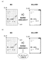
- FIG. 2 and FIG. 3 are diagrams for explaining misalignment or orientation error that should be corrected according to the present embodiment.
- the student has just written “ ⁇ ABC” using the electronic pen 2 in the “answer 1” column of the form 3 (FIG. 2A).
- the teacher visually recognizes what the student wrote on the paper on the screen (FIG. 2B).
- “ ⁇ ABC” 211 is displayed on the right side of the “answer 1” column on the screen.
- “ ⁇ ABC” 211 is displayed. In this case, since “ ⁇ ABC” 211 is an answer to be entered in the column, no particular problem occurs.
- FIG. 3A Even though the student entered “ ⁇ ABC” in the “answer 1” field on the form 3, the screen may appear as if “ ⁇ ABC” 212 was entered in the “answer 2” field.
- FIG. 3B “ ⁇ ABC” 213 may be displayed upside down at a position that is completely unrelated (FIG. 3B).
- the misalignment in FIG. 3A is caused by misalignment when the dot pattern printed paper 3 is set in the printer (details will be described later).
- the orientation error (upside down) in FIG. 3B is caused by the fact that the dot pattern printed paper 3 is set in the wrong orientation with respect to the printer (details will be described later).
- FIG. 4 is a diagram illustrating the configuration of the calibration apparatus 1 and the like.
- the calibration device 1 is connected to the writing information communication device 5 and the reference terminal device 6 via the network 4.
- the one or more electronic pens 2 transmit writing information to the writing information communication device 5 using wireless communication technology.
- the calibration device 1 and the writing information communication device 5 may be directly connected without going through the network 4.
- the calibration apparatus 1 is a general computer, and is managed by an educational company.
- the calibration device 1 includes a central control device (control unit) 11, an input device 12 such as a keyboard and a mouse, an output device 13 such as a display, a screen, and a printer, a main storage device 14, an auxiliary storage device 15, and a communication device 16. . These are connected to each other by a bus.
- the calibration apparatus 1 is usually installed in a classroom.
- the writing information entered by the student with the electronic pen 2 is displayed on the screen of the output device 13, and the teacher gives guidance to the student while visually checking the screen.
- the list unit 34 is a program. Thereafter, when the subject is described as “XX section”, the central control device 11 reads each program from the auxiliary storage device 15 and loads it into the main storage device 14, and then the function of each program (detailed later). Shall be realized.
- the auxiliary storage device 15 stores a learning material database 41, a writing information database 42 and a class information database 43.
- the writing information communication device 5 receives the writing information from the electronic pen 2 and transmits the writing information to the calibration device 1 in a predetermined cycle after sequentially or temporarily storing the writing information.
- One writing information communication device 5 is installed in each classroom where the electronic pen 2 is used, for example.
- the reference terminal device 6 is a general computer, and its configuration (other than the program and the database) conforms to the calibration device 1.
- the reference terminal device 6 is usually arranged in a staff room or the like, and handwriting information or the like is displayed on the output device.
- FIG. 5 (a) is a diagram for explaining the function and information flow of each program and clarifying the problem.
- the worksheet file creation unit 21 is a general document creation application.
- the worksheet file creation unit 21 creates a problem (by being operated by the teacher).
- the problem is intangible electronic data unless printed on paper by a printer. This problem is called “worksheet electronic file”.
- the dot pattern image file generation unit 22 generates a dot pattern.
- the dot pattern is also intangible electronic data unless it is printed on paper by a printer. This dot pattern is called a “dot pattern electronic file”.
- the worksheet image synthesis unit 23 synthesizes the worksheet electronic file and the dot pattern electronic file. What is synthesized is an intangible “worksheet image electronic file with dot pattern”.
- the dot pattern worksheet printing unit 24 receives the dot pattern worksheet image electronic file and prints it on a sheet.
- the printed product is a tangible “worksheet with dot pattern”.
- intangible data is represented by a thick broken line
- tangible paper or the like is represented by a thick solid line (the same applies to the following drawings).
- Fig. 5 (b) is another diagram for explaining the function and information flow of each program and clarifying the problem.
- the worksheet file creation unit 21 creates a worksheet electronic file, as in FIG.
- the dot pattern image file generation unit 22 also generates a dot pattern electronic file.
- the dot pattern printing unit 25 receives the dot pattern electronic file and prints it on the paper.
- the printed product is “dot pattern printed paper”.
- the worksheet image superimposing printing unit 26 receives the worksheet electronic file and prints it on the paper with the dot pattern printed.
- the printed product is a “worksheet with a dot pattern”.
- FIG. 5A and 5B are compared.
- the dot pattern electronic file and the worksheet electronic file are synthesized by the worksheet image synthesis unit 23.
- the origin of the coordinate system of the worksheet electronic file coincides with the origin of the coordinate system of the dot pattern electronic file. That is, the calibration apparatus 1 considers them the same.
- a dot pattern, a problem, and the like are simultaneously printed on a normal sheet without a dot pattern set in a printer (loaded on a tray). Therefore, problems such as the above-described misalignment and orientation error do not occur.
- FIG. 5B the process of printing a dot pattern on a normal sheet and the process of printing a worksheet electronic file (problem etc.) on a dot pattern printed sheet are separated.
- a worksheet with a dot pattern can be printed according to the flow of FIG.
- the dot pattern image file generation unit 22 itself is often an application that requires a license. If the dot pattern image file generation unit 22 is not prepared by itself, the dot pattern worksheet must be printed in the flow of FIG. 5B. In other words, in FIG. 5B, the processing of the dot pattern image file generation unit 22 and the dot pattern printing unit 25 is performed by the printer, etc., and the school purchases the dot pattern printed paper from the printer, etc. Will be processed. Then, problems such as the above-described misalignment and orientation error occur.
- FIG. 6 is a diagram illustrating the function of each program and the flow of information, and an outline of countermeasures against misalignment.
- the dot pattern image file generation unit 22 generates a dot pattern electronic file with dot markers.
- the “dot marker” is a mark such as “+” indicating the positions of the four corners of the dot pattern (details will be described later).
- the coordinate value of the dot marker is a coordinate value of the coordinate system of the dot pattern. This coordinate system and coordinate values are referred to as “dot pattern coordinate system” and “dot pattern coordinate value”.
- the dot pattern printing unit 25 receives the dot marker electronic file with dot markers and prints it on the paper.
- the printed product is “dot pattern printed paper”.
- a dot marker is printed on the dot pattern printed paper together with the dot pattern.
- the worksheet file creation unit 21 is the same as in FIG.
- the calibration marker image file generation unit 27 generates a calibration marker image file.
- the “calibration marker” is a mark such as “ ⁇ ” indicating the positions of the four corners of the worksheet electronic file (details will be described later).
- the worksheet file image synthesis unit 28 receives the worksheet electronic file and the calibration marker image file, synthesizes them, and creates a worksheet electronic file with a calibration marker.
- the worksheet electronic file is, of course, a set of pixel values indicating characters, figures, etc., associated with the coordinate values.
- the worksheet electronic file is also commonly referred to as “content”.
- the coordinate value of the pixel value is a coordinate value of the coordinate system of the worksheet electronic file. This coordinate system and coordinate values are referred to as “content coordinate system” and “content coordinate value”.
- the calibration marker also has content coordinate values.
- the worksheet image superposition printing unit 26 receives the calibration marker-added worksheet electronic file and prints it on the dot pattern printed paper.
- the printed product is a worksheet with a dot pattern. At this stage, the calibration marker is printed on the worksheet with the dot pattern together with the problem and the dot marker is also printed.
- the electronic pen 2 can acquire the coordinate value of the dot marker. This coordinate value is a dot pattern coordinate value.
- the marker coordinate input unit 29 acquires the dot pattern coordinate value of the dot marker via the electronic pen 2. Further, the marker coordinate input unit 29 acquires the content coordinate value of the calibration marker.
- the coordinate conversion coefficient calculation unit 30 acquires at least three combinations of the content coordinate value of the calibration marker and the corresponding dot pattern coordinate value of the dot marker. Now, a “conversion matrix” for converting dot pattern coordinate values into content coordinate values is assumed.
- the conversion matrix has a plurality of components (conversion coefficients). Since the content coordinate value and the dot pattern coordinate value of the combination are known, the coordinate conversion coefficient calculation unit 30 can determine a specific value of the conversion coefficient by solving the simultaneous equations (details will be described later). .
- the calibration device 1 converts the dot pattern coordinate value of the writing information acquired via the electronic pen 2 into the content coordinate value using the conversion matrix including the determined conversion coefficient. Then, the worksheet electronic file and the writing information are superimposed and displayed on the output device 13.
- FIG. 7 is a diagram for explaining the function of each program and the flow of information, and showing an outline of countermeasures against misdirection.
- the worksheet file creation unit 21, the dot pattern image file generation unit 22, the dot pattern printing unit 25, and the worksheet image superimposed printing unit 26 are the same as those in FIG.
- the writing information input unit 31 receives writing information from the electronic pen 2.
- the writing direction estimation unit 32 estimates the writing information rotation angle based on the writing information.
- the writing information rotation angle indicates how many times the paper has been rotated and set on the basis of the correct angle (0 degree) at which the writing information erects on the screen.
- the writing information rotation unit 33 receives the writing information rotation angle and converts the coordinate value of the writing information so as to cancel the writing information rotation angle. For example, when the rotation angle of the writing information is 90 degrees, the coordinate value of the writing information is converted into a coordinate value rotated 90 counterclockwise around the center of the sheet (intersection of diagonal lines).
- FIG. 8 is a diagram illustrating an example of the teaching material database 41.
- the learning material database 41 includes a guide 41a and learning material information 41b.
- the school year column 102 in association with the learning material ID stored in the learning material ID column 101, the school year column 102 includes the grade, the subject column 103 includes the subject, the unit column 104 includes the unit, and the teaching material information pointer column 105.
- the learning material ID in the learning material ID column 101 is an identifier that uniquely identifies the combination of the grade, the subject, and the unit.
- the grade in the grade column 102 is the grade of a class in which classes are performed using the electronic pen 2.
- the subject in the subject column 103 is a subject name of a class conducted using the electronic pen 2.
- the unit in the unit column 104 is a further subdivision of the subject and is the theme of the lesson.
- the pointer to the learning material information in the learning material information pointer column 105 is information indicating the location of the learning material information related to the “worksheet with dot pattern” among the plurality of learning material information 41b. There are as many records of the guide 41a as there are “combinations of grade, subject and unit”.
- the teacher / student flag column 112 in association with the page number stored in the page number column 111, has the teacher / student flag, the dot pattern ID column 113 has the dot pattern ID, and the worksheet electronic file.
- the name column 114 stores a worksheet electronic file name.
- the page number in the page number column 111 is the page number of each page of the teaching material.
- the teacher / student flag in the teacher / student flag column 112 is a symbol indicating a person who can enter characters or the like on the page using the electronic pen 2. “T” indicates that the teacher can fill in, and “S” indicates that the student can fill in. If both can fill in, two records are created for the page.
- the dot pattern ID in the dot pattern ID column 113 is an identifier that uniquely identifies the dot pattern.
- the page number and the dot pattern ID have a one-to-one correspondence.
- the worksheet electronic file name in the worksheet electronic file name column 114 is a name for each page of the worksheet electronic file. There is a one-to-one correspondence between page numbers and worksheet electronic file names. It is assumed that the worksheet electronic file 115 itself is also stored in the teaching material database 41. There are as many educational material information 41b as there are educational material IDs.
- Writing information database In the writing information database 42, writing information (FIG. 1B) is stored.
- FIG. 9 is a diagram illustrating an example of the class information database 43.
- the class information database 43 includes a guide 43a and class information 43b.
- the grade column 122 in association with the class ID stored in the class ID column 121, the grade column 122 has the grade, the class name column 123 has the class name, the teacher name column 124 has the teacher name, A pointer to class information is stored in the information pointer column 125.
- the class ID in the class ID column 121 is an identifier that uniquely identifies the class.
- the grade in the grade column 122 is the same as the grade in FIG.
- the class name in the class name column 123 is a name of a class belonging to the school year.
- the teacher name in charge teacher name column 124 is the name of the teacher in charge of the class.
- the pointer to the class information in the class information pointer column 125 is information indicating the location of the class information related to the class among the plurality of class information 43b. There are as many records of the guide 43a as the number of class IDs.
- the pen ID column 132 stores the pen ID
- the student name column 133 stores the student name.
- the attendance number in the attendance number column 131 is the order in which the teacher calls the students to check attendance in the class, and in many cases, the attendance numbers are numbers in which the student names are arranged in alphabetical order.
- the pen ID in the pen ID column 132 is an identifier that uniquely identifies the electronic pen 2.
- the student name in the student name column 133 is the name of the student.
- FIG. 10 is a diagram illustrating another example of the class information database 43.
- the class information database 43 in FIG. 10 is a modification of the class information database 43 in FIG. In FIG. 9, it is assumed that each student uses a different electronic pen 2. In FIG. 10, it is assumed that there are as many electronic pens 2 as there are students in one class (for example, 40), and that 40 electronic pens 2 are reused in all classes.
- the class information database 43 in FIG. 10 includes guides 43c, pen information 43d, and student information 43e. Compared with the guide 43a in FIG. 9, the guide 43c in FIG. 10 has a pointer field 145 to pen information and a pointer field 146 to student information instead of the pointer field 125 to class information.
- the pointer to the pen information stored in the pen information pointer column 144 is information indicating the location of the pen information 43d.
- the pointer to the student information stored in the student information pointer field 146 is information indicating the location of the student information related to the class among the plurality of student information 43e. Since other configurations are the same as those in FIG. 9, detailed description of each of the columns 141 to 144 is omitted.
- the pen information 43d has a configuration in which the student name column 133 is deleted from the class information 43b (FIG. 9). Therefore, detailed description of each column 161, 162 is omitted. However, there is only one pen information 43d regardless of the number of classes.
- the student information 43e has a configuration in which the pen ID column 132 is deleted from the class information 43b (FIG. 9). Therefore, detailed description of each column 171 and 172 is omitted. However, there are as many pen information 43d as the number of class IDs.
- FIG. 11 is a diagram for explaining the relationship between the dot pattern coordinate system and the content coordinate system.
- FIG. 11A shows a worksheet 221 (paper surface) with a dot pattern distributed to students. The origin of the dot pattern coordinate system is at the upper left point (0, 0) of the dot pattern worksheet 221.
- a character string “problem”, a rectangular parallelepiped, a cylindrical figure, and the like that are printed in a portion surrounded by a broken line on the upper and left sides of the worksheet 221 with a dot pattern are portions derived from the worksheet electronic file. These character strings, graphics, and the like are referred to as “content-derived data”.
- the content-derived data has content coordinate values in the content coordinate system.
- the origin of the content coordinate system is a point corresponding to the point 222 where two broken lines contact.
- the coordinate value of the point 222 read by the electronic pen 2 is not (0, 0).
- the electronic pen 2 reads the dot pattern coordinate value (s, t) from the point 222 (where s ⁇ 0 and t ⁇ 0).
- “ ⁇ ABC” 223 is the handwriting of the student.
- the electronic pen 2 reads the dot pattern coordinate value (p, q) from a certain point “ ⁇ ABC” 223.
- FIG. 11B shows a display on the screen of the output device 13.
- the worksheet electronic file 224 has a content coordinate system, and its origin is a point 225 [0, 0].
- the content-derived data is displayed at a position indicated by its own content coordinate value.
- the calibration device 1 recognizes the dot pattern coordinate value of the student handwriting 223 read by the electronic pen 2 as the content coordinate value in the content coordinate system (in the first place, the dot pattern coordinate value and the content coordinate value are distinguished from each other).
- the student's handwriting “CABC” 226 is displayed slightly shifted from the right side of the original position “Answer 1” to the lower right.
- the calibration apparatus 1 applies the dot pattern coordinate values (p, q) “p” and “q” to the content coordinate system without conversion. This is expressed as [p, q] in FIG. 11B and FIG. 12A described later. Lowercase letters such as p and q are dot pattern coordinate values, and uppercase letters such as P and Q are content coordinate values. (,) Indicates that the calibration apparatus 1 recognizes that the value in it is a dot pattern coordinate value. [,] Indicates that the calibration apparatus 1 recognizes that the value therein is the content coordinate value. It is necessary to convert the dot pattern coordinate value into the content coordinate value by some method.
- FIG. 12 is a diagram for explaining the conversion of coordinate values.
- the dot pattern coordinate value of the writing information is not converted to the content coordinate value. Therefore, the position where “ ⁇ ABC” is displayed is shifted.
- the dot pattern coordinate value of the writing information is converted to the content coordinate value. Therefore, “ ⁇ ABC” is displayed at the correct position.
- the conversion matrix (T) converts p into P and q into Q.
- FIG. 13 is a diagram for explaining the transformation matrix.
- a transformation matrix (T) 232 shown in FIG. 13A is a square matrix of 3 rows ⁇ 3 columns. Of the nine components included in the transformation matrix 232, six in the first and second rows are transformation coefficients. Now, three sets of dot pattern coordinate values (x 1 , y 1 ), (x 2 , y 2 ), and (x 3 , y 3 ), and three sets of content coordinate values (X 1 , Y 3 ) corresponding to them. 1 ), (X 2 , Y 2 ) and (X 3 , Y 3 ) are given. Then, as is clear from FIG.
- FIG. 13A by solving the six simultaneous equations in the dashed rectangle, the six transformation coefficients (a, b, c, d, e) which are the solutions (unknown numbers) are obtained. And f) can be determined.
- FIG. 13B is a diagram illustrating the function of the transformation matrix in an intuitive manner.
- FIG. 14 is a diagram for explaining the association between the dot marker and the calibration marker.
- the worksheet electronic file 234 (with calibration markers) is obtained by attaching calibration markers 235a, 235b, 235c, and 235d to the four corners of the worksheet electronic file 233.
- the dot pattern printed paper 237 is obtained by printing the dot pattern printed paper 236 together with the dot markers 238a, 238b, 238c, and 238d at the four corners.
- a dot pattern worksheet 239 is obtained by printing the worksheet electronic file 234 on the dot pattern printed paper 237.
- Position alignment processing procedure 15 and 16 are flowcharts of the position alignment processing procedure.
- the position alignment processing procedure corresponds to FIG. It is assumed that the class information data pace 43 (FIGS. 9 and 10) has already been completed at the start of the position alignment processing procedure.
- the worksheet file creation unit 21 creates a worksheet electronic file. Specifically, the worksheet file creation unit 21 accepts that a user (teacher) creates a worksheet electronic file including a question sentence, a figure, and the like via the input device 12. The worksheet electronic file is created so that one page of a problem or the like to be distributed becomes one worksheet electronic file. When the user creates a worksheet electronic file that spans multiple pages, the worksheet file creation unit 21 may divide it into pages. Furthermore, the worksheet file creation unit 21 accepts that the user inputs a worksheet electronic file name for each page.
- step S ⁇ b> 302 the worksheet file creation unit 21 creates the teaching material database 41. Specifically, first, the worksheet file creation unit 21 sets a new record of the teaching material information 41b in the teaching material database 41 (FIG. 8) as the number of worksheet electronic files (number of pages) created in step S301. ) And store the page numbers as 1, 2, 3,... In the page number column 111 of the new record. Second, the worksheet file creation unit 21 stores the worksheet electronic file name received in step S301 in the worksheet electronic file name column 114 of the new record.
- the worksheet file creation unit 21 accepts that the user designates a teacher / student flag for each page, and stores the accepted teacher / student flag in the teacher / student flag column 112 of the new record.
- the record on the page is copied into two, and “T” and “S” are stored in the teacher / student flag column 112 of each record.
- the worksheet file creation unit 21 stores the dot pattern ID in the dot pattern ID column 113 of the new record.
- the worksheet file creation unit 21 stores a dot pattern ID related to an unused dot pattern for each page number.
- the worksheet file creation unit 21 creates a new record of the guide 41a of the teaching material database 41 (FIG. 8).
- the worksheet file creation unit 21 accepts that a user inputs a school year, a subject, and a unit via the input device 12.
- the worksheet file preparation part 21 memorize
- the learning material ID is numbered and stored in the learning material ID column 101.
- the worksheet file creation unit 21 stores the pointer to the learning material information in the pointer column 105 to the learning material information of the new record.
- step S303 the calibration marker image file generation unit 27 generates a calibration marker image file.
- step S304 the worksheet file image composition unit 28 creates a worksheet electronic file with calibration markers. Specifically, the worksheet file image synthesis unit 28 synthesizes the worksheet electronic file created in step S301 and the calibration marker image file generated in step S303, and the calibration marker-added worksheet electronic Create a file.
- step S305 the dot pattern image file generation unit 22 generates a dot pattern electronic file with dot markers. At this time, the dot pattern image file generation unit 22 numbers the dot pattern ID of the generated dot pattern.
- the dot pattern printing unit 25 creates a dot pattern printed paper. Specifically, the dot pattern printing unit 25 prints the dot pattern and the dot pattern ID on the paper (paper in a blank state without the dot pattern) via the output device 13. The number of printed sheets (usually the number of students) is specified by the user (teacher). It is assumed that the dot pattern ID is printed on an inconspicuous portion of the paper sufficiently small to be visible with the naked eye.
- the worksheet image superposition printing unit 26 creates a worksheet with a dot pattern. Specifically, first, the worksheet image superposition printing unit 26 accepts that a user (teacher) selects a worksheet electronic file name via the input device 12. For example, the worksheet image superposition printing unit 26 displays the guide 41a of the teaching material database 41 (FIG. 8) on the screen of the output device 13, and accepts that the user selects an arbitrary record. Then, using the pointer to the learning material of the selected record as a search key, the corresponding learning material information 41b is acquired, the acquired learning material information 41b is displayed, and it is accepted that the user selects an arbitrary record.
- the worksheet image overlay printing unit 26 acquires the worksheet electronic file name and the dot pattern ID of the record of the selected teaching material information 41b. Third, the worksheet image overlay printing unit 26 prints the worksheet electronic file having the acquired worksheet electronic file name on the dot pattern printed paper having the acquired dot pattern ID and equal to the number of students. .
- step S308 the electronic pen 2 accepts a tap on the dot marker (places the pen tip on the dot marker). Specifically, the electronic pen 2 accepts that the user (teacher) uses the electronic pen 2 to tap any one of the dot markers at the four corners of the printed dot pattern-added worksheet. . Then, the electronic pen 2 reads the dot pattern coordinate value of the dot marker.
- the marker coordinate input unit 29 acquires the coordinate value of the dot marker. Specifically, the marker coordinate input unit 29 receives the dot pattern coordinate value of the dot marker from the electronic pen 2. In step S310, the marker coordinate input unit 29 displays the tap position on the screen. Specifically, the marker coordinate input unit 29 displays the received dot pattern coordinate value on the screen of the output device 13. At this time, the marker coordinate input unit 29 displays the tapped position within the frame of the worksheet with the dot pattern with a conspicuous symbol such as “ ⁇ ”.
- step S311 the marker coordinate input unit 29 displays a confirmation message. Specifically, the marker coordinate input unit 29 reads, “Are you tapping this way? If so, press the“ F1 ”key, otherwise press the“ F2 ”key.” Message is displayed on the screen of the output device 13.
- step S312 the marker coordinate input unit 29 determines whether confirmation has been made. Specifically, in the above example, if the marker coordinate input unit 29 determines that the user has pressed the “F1” key (step S312 “YES”), the process proceeds to step S313, and the user presses the “F2” key. If it is determined that the button is pressed (“NO” in step S312), the process returns to step S308.
- step S313 the marker coordinate input unit 29 stores the coordinate value. Specifically, the marker coordinate input unit 29 temporarily stores the dot pattern coordinate value received in step S ⁇ b> 309 in the main storage device 14.
- step S314 the marker coordinate input unit 29 determines whether or not three coordinate values are stored. Specifically, if the number of dot pattern coordinate values temporarily stored in the main storage device 14 has reached 3 (step S314 “YES”), the marker coordinate input unit 29 proceeds to step S315, In other cases (step S314 “NO”), the process returns to step S308.
- the marker coordinate input unit 29 may execute the following processing. Calculate an equation of a straight line that passes through the dot pattern coordinate value acquired for the first time and the dot pattern coordinate value acquired for the second time. -It is determined whether the dot pattern coordinate value acquired for the third time satisfies the equation. If not satisfied, the process proceeds to step S310. If satisfied, a message “Please tap again” is displayed, and the process returns to step S308. As long as the user consciously taps the dot markers at the four corners, these processes are unnecessary. However, for example, when the user's hand shakes and the tap is repeated twice within a short period, these processes are effective.
- step S315 the marker coordinate input unit 29 acquires the content coordinate value of the calibration marker. Specifically, first, the marker coordinate input unit 29 acquires three content coordinate values respectively corresponding to the three dot pattern coordinate values stored in step S313. Now, it is assumed that the stored coordinate values are (x 1 , y 1 ), (x 2 , y 2 ) and (x 3 , y 3 ). Hereinafter, in step S308, the description will be continued with an example in which the user taps in the order of the upper left dot marker ⁇ the upper right dot marker ⁇ the lower left dot marker.
- the marker coordinate input unit 29 acquires content coordinate values in the order of the upper left calibration marker ⁇ the upper right calibration marker ⁇ the lower left calibration marker from the content coordinate values of the four calibration markers. . It is assumed that the acquired coordinate values are [X 1 , Y 1 ], [X 2 , Y 2 ] and [X 3 , Y 3 ].
- step S316 the coordinate conversion coefficient calculation unit 30 calculates a conversion coefficient. Specifically, known values (x 1 , y 1 ), (x 2 , y 2 ) and (x 3 , y 3 ), and [X 1 , Y 1 ], [X 2 , Y 2] and [X 3, Y 3] is substituted into the six simultaneous equations (dashed in rectangular FIG. 13 (a)), by solving the simultaneous equations, transform coefficient is unknown a, b, c, Find d, e and f.
- the coordinate conversion coefficient calculation unit 30 may use any known method.
- step S317 the worksheet image superposition printing unit 26 matches the coordinate values. Specifically, first, the worksheet image superimposition printing unit 26 uses the conversion matrix having the conversion coefficient acquired in step S316 as a component, and the coordinate value 204 of the writing information acquired by the electronic pen 2 (see FIG. 1 (b)) is converted into content coordinate values.
- step S318 the worksheet image overlay printing unit 26 displays the writing information. Specifically, the worksheet image superimposition printing unit 26 displays the content coordinate value (derived from the electronic pen 2) converted in step S317 on the screen of the output device 13 with the content-derived data superimposed. At this time, the positional deviation of the writing information is eliminated. Thereafter, the position alignment processing procedure ends.
- FIG. 17 is a diagram illustrating a method of displaying a plurality of printed dot pattern worksheets on the same screen.
- the educational material information 41b includes records relating to the page (one page) 241 and the page (two pages) 242 of FIG. Since the pages are different, the dot pattern printed on the paper surface (one page) 241 and the dot pattern printed on the paper surface (two pages) 242 are different. Processing for displaying these papers side by side on the screen of the output device 13 will be described below.
- the simultaneous list unit 34 accepts that the user selects two records for pages that the user desires to display side by side from the learning material information 41b. (2) The simultaneous list unit 34 acquires the worksheet electronic file 115 of the selected record. (3) The simultaneous list unit 34 acquires the dot pattern ID of the selected record. (4) The simultaneous list section 34 prints two worksheets with dot patterns by printing a dot pattern with a corresponding dot pattern ID on the acquired worksheet electronic file. On each worksheet with a dot pattern, dot markers (“+” in the figure) are printed at the four corners.
- the simultaneous list unit 34 accepts that the user taps the dot marker on the page (page 1) 241 and the dot marker on the page (page 2) 242 using the electronic pen 2 in a predetermined order.
- the predetermined order is, for example, upper left ⁇ upper right ⁇ lower left ⁇ lower right for the first page, and then upper left ⁇ upper right ⁇ lower left ⁇ lower right for the second page. In FIG. 17, this order is written in “ ⁇ ”.
- the simultaneous list unit 34 acquires a difference obtained by subtracting the coordinate value of the upper left calibration marker from the coordinate value of the upper right calibration marker of the worksheet electronic file. (7) The simultaneous list unit 34 adds the difference acquired in (6) to the x coordinate values of all characters, figures, etc. in the worksheet electronic file on the second page. (8) The simultaneous list unit 34 acquires a difference obtained by subtracting the x coordinate value of the upper left dot marker from the x coordinate value of the upper right dot marker. (9) The simultaneous list unit 34 adds the difference acquired in (8) to the x coordinate values of all the handwriting information acquired by the electronic pen 2 from the page (2 pages) 242.
- the simultaneous list unit 34 considers all the content coordinate values of the first and second pages as the content coordinate values of the first page, and outputs the worksheet electronic files of the first and second pages. 13 screens.
- the simultaneous list unit 34 considers all the dot pattern coordinate values of the first and second pages as the dot pattern coordinate values of the first page, and outputs writing information of the first and second pages. It is displayed on the screen of the device 13.
- the screen of the output device 13 becomes a screen 243 in FIG. That is, the upper right of the first page and the upper left of the second page overlap, and the lower right of the first page overlaps with the lower left of the second page, and two pages are displayed side by side.
- FIG. 17 there are cases where there are “3 pages” and after. However, the description thereof is the same as described above, and will be omitted.
- FIG. 18 is a diagram for explaining a method of displaying the front and back surfaces of the printed worksheet with a dot pattern on the same screen.
- the processing of the simultaneous list unit 34 in this case is the same as the above (1) to (11).
- “first page” or “first page” is read as “front side”
- “second page” or “second page” is called “back side”. Replace it.
- “print two dot pattern worksheets” is read as “two dot pattern worksheets are printed on both sides of one sheet”.
- FIG. 19 is a diagram for explaining another method for displaying a plurality of pages of a printed worksheet with a dot pattern on the same screen.
- the paper surface (2 pages) 244 is in the landscape orientation.
- the processing of the simultaneous list unit 34 in this case is as follows (12) to (20).
- the simultaneous list unit 34 performs the processes (1) to (4). (13) The simultaneous list unit 34 accepts that the user taps the dot marker on the paper surface (1 page) 241 and the dot marker on the paper surface (2 pages) 244 using the electronic pen 2 in a predetermined order.
- the predetermined order is, for example, upper left ⁇ upper right ⁇ lower left ⁇ lower right for the first page, and then lower left ⁇ upper left ⁇ lower right ⁇ upper right for the second page (based on the vertical position). In FIG. 19, this order is written in “ ⁇ ”.
- the simultaneous list unit 34 acquires the difference 1 obtained by subtracting the x coordinate value of the upper left calibration marker from the x coordinate value of the upper right calibration marker in the worksheet electronic file. Further, a difference 2 is obtained by subtracting the y coordinate value of the upper left calibration marker from the y coordinate value of the lower left calibration marker. Then, the value of (difference 2 ⁇ difference 1 ) / 2 is calculated. (15) The simultaneous list unit 34 converts the coordinate values of all characters, figures, etc. in the worksheet electronic file on the second page into coordinate values rotated 90 degrees clockwise around the origin. (16) The simultaneous list unit 34 adds the difference 1 acquired in (14) to the x coordinate values of all characters, figures, etc. in the worksheet electronic file on the second page. Further, (difference 2 ⁇ difference 1 ) / 2 acquired in (14) is added to the y coordinate value.
- the simultaneous list unit 34 obtains a difference 3 obtained by subtracting the x coordinate value of the upper left dot marker from the x coordinate value of the upper right dot marker. Further, a difference 4 is obtained by subtracting the y coordinate value of the upper left dot marker from the y coordinate value of the lower left dot marker. Then, the value of (difference 4 ⁇ difference 3 ) / 2 is calculated. (18) The simultaneous list unit 34 converts the coordinate values of all the writing information acquired by the electronic pen 2 from the page (page 2) 244 into coordinate values rotated 90 degrees clockwise around the origin. (19) The simultaneous list unit 34 adds the difference 3 acquired in (17) to the x coordinate values of all the writing information acquired by the electronic pen 2 from the page (page 2) 244. Further, the value of (difference 4 ⁇ difference 3 ) / 2 acquired in (17) is added to the y coordinate value. (20) The simultaneous list unit 34 performs the processes (10) to (11).
- the screen of the output device 13 becomes a screen 245 of FIG. That is, the second page is rotated 90 degrees clockwise, and the middle point between the upper right and lower right of the first page and the middle of the second page (based on the vertical position) between the lower left and lower right.
- the dots overlap and two pages are displayed side by side.
- “page 1” and “page 2” may be “front surface” and “back surface”, respectively. However, the description thereof is the same as described above, and will be omitted.
- FIG. 20 is a diagram illustrating a method for displaying writing information of a plurality of electronic pens 2 on the same screen.
- the processing of the simultaneous list unit 34 for displaying such a screen is as follows (21) to (31).
- the simultaneous list unit 34 receives writing information from the six electronic pens 2.
- the simultaneous list unit 34 refers to the class information 43b (or pen information 43d) and acquires an attendance number corresponding to the pen ID of the writing information.
- h 1 is a value obtained by subtracting the x coordinate value of the upper left dot marker from the x coordinate value of the upper right dot marker (the horizontal width of the paper surface).
- h 2 is any positive number indicating the horizontal length of the gap between the sheets.
- v 1 is a value obtained by subtracting the y coordinate value of the upper left dot marker from the y coordinate value of the lower left dot marker (the height of the paper surface).
- v 2 is any positive number indicating the vertical length of the gap between the sheets.
- the simultaneous list unit 34 displays all writing information and all worksheet electronic files on the screen of the output device 13.
- the screen of the output device 13 becomes a screen 246 in FIG.
- 21 and 22 are diagrams for explaining a method of displaying only the selected portion.
- a student is provided with a worksheet (paper surface) 251 with a dot pattern on which a question or the like is printed.
- the lower half of the page is an answer field, and teachers want to see only this answer field on the screen for all students. Processing of the simultaneous list unit 34 for displaying such a screen is as follows (32) to (40).
- the simultaneous list unit 34 accepts that the user (teacher) specifies a range to be displayed on the screen on the dot pattern worksheet. For example, when the user wants to display a range surrounded by a broken line in FIG. 22 on the screen, the user taps the four corners (indicated by ⁇ ) with the electronic pen 2.
- the simultaneous list unit 34 acquires the coordinate values of the four corners from the electronic pen 2.
- the acquired coordinate values are (5, 60) for the upper left, (75, 60) for the upper right, (5, 110) for the lower left, and (75, 110) for the lower right.
- FIG. 23 is a diagram for explaining orientation correction in a rectangular sheet.
- the paper when the paper is “rectangular”, it means “rectangular” other than “square”.
- the Japanese writing information is displayed on the screen as indicated by reference numeral R01 or R03.
- a language written from right to left, such as Arabic, is displayed on the screen as indicated by reference numeral R05.
- the dot pattern printed paper is set upside down, the writing information to be displayed as indicated by the symbol R01 is displayed as indicated by the symbol R02.
- the writing information to be displayed as indicated by reference numeral R03 is displayed as indicated by reference numeral R04
- the writing information to be displayed as indicated by reference numeral R05 is displayed as indicated by reference numeral R06.
- “ ⁇ ” is the order in which the user (student) writes. Since the writing information has the current time (FIG. 1B), the calibration apparatus 1 can identify the order.
- FIG. 24 is a diagram for explaining orientation correction on a square sheet.
- Symbols Q01, Q05, and Q09 in FIG. 24 correspond to symbols R01, R03, and R05 in FIG. 23, respectively (which should originally be displayed in this way).
- the symbols Q03, Q07, and Q11 in FIG. 24 correspond to the symbols R02, R04, and R06 in FIG. 23 (reversed upside down).
- the writing information of reference signs Q02, Q06, and Q10 is displayed rotated 90 degrees clockwise with reference to the writing information of reference signs Q01, Q05, and Q09.
- the writing information of reference signs Q04, Q08, and Q12 is displayed rotated 270 degrees clockwise with reference to the writing information of reference signs Q01, Q05, and Q09.
- the square dot pattern printed paper has a large number of orientation error variations compared to the rectangular dot pattern printed paper because there is no distinction between vertical and horizontal directions.
- FIG. 25 is a diagram for explaining terms and basic concepts in the orientation correction processing procedure.
- FIG. 25 (a) is hiragana “ni”.
- Ni is a character consisting of three strokes.
- a group of images connected by black pixels is called a “connected component” 261.
- the vertical first image, the horizontal second image, and the horizontal third image are separate connected components.
- “Kusakanmuri” is one connected component.
- a rectangle circumscribing the connected component is referred to as a “circumscribed rectangle” 262.
- “Ni” has three circumscribed rectangles. Some circumscribed rectangles belonging to the same character may overlap.
- One or a plurality of circumscribed rectangles located within a predetermined distance range are grouped.
- the calibration apparatus 1 recognizes this group as a character.
- a rectangle circumscribing all circumscribed rectangles included in a character is referred to as “integrated circumscribed rectangle” 263 (FIG. 25B).
- FIG. 25 (c) shows a state in which the student has written “Michiko Fujiwara makes Emperor Akiko Go Ichijo enter the daughter” in horizontal writing using the electronic pen 2 on the worksheet with the dot pattern. 264).
- 25 (d) and 25 (e) are enlarged views of the first two characters (reference numerals 265 to 268). Now, consider comparing the coordinate values of the center points (intersections of diagonal lines) of two adjacent integrated circumscribed rectangles. “ ⁇ x” indicates how much the x coordinate value of the central point of a certain integrated circumscribed rectangle has increased (rightward in the positive direction) compared to the x coordinate value of the central point of the previous integrated circumscribed rectangle. is there.
- ⁇ y In the case of horizontal writing from left to right (FIG. 25 (d)), ⁇ x is generally larger than ⁇ y. On the other hand, in the case of vertical writing from top to bottom (FIG. 25E), ⁇ y is generally larger than ⁇ x.
- FIG. 26 is a flowchart of the orientation correction processing procedure for rectangular paper. As a premise for starting the processing procedure, it is assumed that the electronic pen 2 reads writing information from a single worksheet with a dot pattern, and the writing information is stored in the writing information database 42.
- step S341 the writing direction estimation unit 32 extracts a connected component. Specifically, the writing direction estimation unit 32 reproduces the handwriting entered by the user (student) based on the coordinate value and the pixel value included in the writing information. A plurality of connected components are extracted from the handwriting by a known method.
- step S342 the writing direction estimation unit 32 generates a circumscribed rectangle. Specifically, the writing direction estimation unit 32 generates a circumscribed rectangle for all extracted connected components by a known method.
- step S343 the writing direction estimation unit 32 generates an integrated circumscribed rectangle. Specifically, first, the writing direction estimation unit 32 groups all generated circumscribed rectangles within a predetermined distance range. Secondly, the writing direction estimation unit 32 generates an integrated circumscribed rectangle by a known method for all circumscribed rectangles (corresponding to characters) belonging to each group.
- step S344 the writing direction estimation unit 32 acquires the number (N) of integrated circumscribed rectangles.
- step S345 the writing direction estimation unit 32 sets variables “AvrX” and “AvrY”, and substitutes “0” for each.
- step S346 the writing direction estimation unit 32 sets a variable “i” and substitutes 2 for “i”.
- step S347 the writing direction estimation unit 32 calculates ⁇ x. Specifically, the writing direction estimation unit 32 acquires the x coordinate value of the center point of the i-th integrated circumscribed rectangle and the x coordinate value of the center point of the (i ⁇ 1) -th integrated circumscribed rectangle, and the former A value obtained by subtracting the latter from is assumed to be ⁇ x.
- step S348 the writing direction estimation unit 32 calculates ⁇ y. Specifically, the writing direction estimation unit 32 acquires the y coordinate value of the center point of the i-th integrated circumscribed rectangle and the y coordinate value of the center point of the (i ⁇ 1) -th integrated circumscribed rectangle, and the former A value obtained by subtracting the latter from is assumed to be ⁇ y.
- step S350 the writing direction estimation unit 32 determines whether or not
- step S351 the writing direction estimation unit 32 determines whether or not
- Th1 means “first threshold”.
- the first threshold is set based on a general distance between rows. Specifically, the writing direction estimation unit 32 proceeds to step S354 if
- step S352 the writing direction estimation unit 32 determines whether i ⁇ N. Specifically, the writing direction estimation unit 32 proceeds to step S353 if i ⁇ N holds (step S352 “YES”), and proceeds to step S360 otherwise (step S352 “NO”). Incidentally, when i ⁇ N holds, the processing is not completed up to the last integrated circumscribed rectangle.
- step S353 the writing direction estimation unit 32 adds 1 to the variable “i”. Thereafter, the process returns to step S347.
- step S354 the writing direction estimation unit 32 determines whether or not ⁇ y> 0. Specifically, the writing direction estimation unit 32 proceeds to step S360 if ⁇ y> 0 is satisfied (step S354 “YES”), and proceeds to step S359 otherwise (step S354 “NO”).
- step S354 “YES” ⁇ y> 0 holds
- the integrated circumscribed rectangle is broken from top to bottom.
- the examples of the symbols R01 and R05 in FIG. 23 pass through the “YES” path.
- ⁇ y> 0 does not hold, the integrated circumscribed rectangle is broken from bottom to top.
- the examples of the codes R02 and R06 in FIG. 23 pass through the “NO” path.
- step S355 the writing direction estimation unit 32 determines whether or not
- Th2 means “second threshold”. The second threshold is set based on a general distance between columns. Specifically, the writing direction estimation unit 32 proceeds to step S358 when
- step S356 the writing direction estimation unit 32 determines whether i ⁇ N. Specifically, the writing direction estimation unit 32 proceeds to step S357 when i ⁇ N is satisfied (step S356 “YES”), and proceeds to step S360 otherwise (step S356 “NO”). Incidentally, when i ⁇ N holds, the processing is not completed up to the last integrated circumscribed rectangle.
- step S357 the writing direction estimation unit 32 adds 1 to the variable “i”. Thereafter, the process returns to step S347.
- step S358 the writing direction estimation unit 32 determines whether or not ⁇ x> 0. Specifically, the writing direction estimation unit 32 proceeds to step S359 when ⁇ x> 0 holds (step S358 “YES”), and proceeds to step S360 otherwise (step S358 “NO”).
- step S358 “YES” the integrated circumscribed rectangle is line-turned from left to right.
- the example of the code R04 in FIG. 23 passes through the “YES” path.
- ⁇ x> 0 does not hold, the integrated circumscribed rectangle is broken from right to left.
- the example of the symbol R03 in FIG. 23 passes through the “NO” path.
- step S359 the writing direction estimation unit 32 determines the writing information rotation angle as 180 degrees.
- step S360 the writing direction estimation unit 32 determines the writing information rotation angle as 0 degrees.
- step S361 the writing information rotating unit 33 corrects the coordinate value of the writing information. Specifically, the writing information rotation unit 33 converts the coordinate value of the writing information so as to cancel the determined writing information rotation angle. For example, when the writing information rotation angle is determined to be 180 degrees, the coordinate value of the writing information is converted into a coordinate value rotated 180 degrees counterclockwise around the center of the paper (intersection of diagonal lines). If the writing information rotation angle is determined to be 0 degrees, nothing is done. Thereafter, the direction correction processing procedure is terminated.
- FIG. 27 is a flowchart of the orientation correction processing procedure (part 1) for a square sheet. Steps S341 to S353, S355 to S357, and S359 to S361 in FIG. 27 are the same as S341 to S353, S355 to S357, and S359 to S361 in FIG. However, “proceed to step S354” in the description of step S351 in FIG. 26 is read as “proceed to step S354b”. Similarly, “proceed to step S358” in the description of step S355 in FIG. 26 is read as “proceed to step S358b”.
- step S354b the writing direction estimation unit 32 determines whether or not AvrX> 0. Specifically, the writing direction estimation unit 32 proceeds to step S354c when AvrX> 0 holds (step S354b “YES”), and proceeds to step S354d otherwise (step S354b “NO”). Incidentally, when AvrX> 0 holds, the integrated circumscribed rectangles are arranged from left to right. Similarly, when AvrX> 0 does not hold, the integrated circumscribed rectangles are arranged from right to left.
- step S354c the writing direction estimation unit 32 determines whether or not AvrY> 0. Specifically, the writing direction estimation unit 32 proceeds to step S360 when AvrY> 0 is satisfied (step S354c “YES”), and proceeds to step S359 otherwise (step S354c “NO”).
- step S354c the integrated circumscribed rectangle is broken from top to bottom.
- the examples of the codes Q01 and Q08 in FIG. 24 pass through the “YES” path.
- AvrY> 0 does not hold, the integrated circumscribed rectangle is broken from bottom to top.
- the example of the code Q11 in FIG. 24 passes through the “NO” path.
- step S354d the writing direction estimation unit 32 determines whether or not AvrY> 0. Specifically, the writing direction estimation unit 32 proceeds to step S360 when AvrY> 0 is satisfied (step S354d “YES”), and proceeds to step S359 otherwise (step S354d “NO”).
- step S354d YES
- step S354d NO
- AvrY> 0 holds, the integrated circumscribed rectangle is broken from top to bottom.
- the example of the code Q09 in FIG. 24 passes through the “YES” path.
- AvrY> 0 does not hold, the integrated circumscribed rectangle is broken from bottom to top.
- the examples of the codes Q03 and Q06 in FIG. 24 pass through the “NO” path.
- step S358b the writing direction estimation unit 32 determines whether or not AvrY> 0. Specifically, the writing direction estimation unit 32 proceeds to step S358c if AvrY> 0 holds (step S358b “YES”), and proceeds to step S358d otherwise (step S358b “NO”).
- step S358c the integrated circumscribed rectangles are arranged from top to bottom.
- step S358d the integrated circumscribed rectangles are arranged from the bottom to the top.
- step S358c the writing direction estimation unit 32 determines whether or not AvrX> 0. Specifically, the writing direction estimation unit 32 proceeds to step S359 when AvrX> 0 holds (step S358c “YES”), and proceeds to step S360 otherwise (step S358c “NO”).
- step S358c the integrated circumscribed rectangle is broken from left to right.
- the example of the symbol Q12 in FIG. 24 passes through the “YES” path.
- AvrX> 0 does not hold, the integrated circumscribed rectangle is broken from right to left.
- the examples of the symbols Q02 and Q05 in FIG. 24 pass through the “NO” path.
- step S358d the writing direction estimation unit 32 determines whether or not AvrX> 0. Specifically, the writing direction estimation unit 32 proceeds to step S359 when AvrX> 0 holds (step S358d “YES”), and proceeds to step S360 otherwise (step S358d “NO”).
- step S358d the integrated circumscribed rectangle is broken from left to right.
- the examples of the codes Q04 and Q07 in FIG. 24 pass through the “YES” path.
- AvrX> 0 does not hold, the integrated circumscribed rectangle is broken from right to left.
- the example of the symbol Q10 in FIG. 24 goes through the “NO” path.
- the writing direction estimation unit 32 cannot completely correct the orientation error. For example, when passing through the path of step S354c “YES”, it is determined that the writing information rotation angle is 0 degree for the examples of the codes Q01 and Q08 in FIG. There is no problem with the example of the code Q01. However, for the example of the code Q08, the writing direction estimation unit 32 recognizes that the writing information rotation angle is 0 degrees, even though the actual writing information rotation angle is 270 degrees. Therefore, the writing information of the code Q08 is not upright. Therefore, in the orientation correction processing procedure (part 2) described next, the writing direction estimation unit 32 receives the judgment of the user (teacher) and solves this problem.
- FIG. 28 is a flowchart of the orientation correction processing procedure (part 2) for square paper. Steps S341 to S353, S355 to S357, and S359 to S361 in FIG. 28 are the same as S341 to S353, S355 to S357, and S359 to S361 in FIG. Furthermore, steps S354b and S358b in FIG. 28 are the same as steps S354b and S358b in FIG.
- step S354c the writing direction estimation unit 32 determines whether or not AvrY> 0. Specifically, the writing direction estimation unit 32 proceeds to step S354e if AvrY> 0 holds (step S354c “YES”), and proceeds to step S359 otherwise (step S354c “NO”). Incidentally, when AvrY> 0 holds, the integrated circumscribed rectangle is broken from top to bottom.
- step S354d the writing direction estimation unit 32 determines whether or not AvrY> 0. Specifically, the writing direction estimation unit 32 proceeds to step S360 if AvrY> 0 holds (step S354d “YES”), and proceeds to step S354f otherwise (step S354d “NO”).
- step S354e the writing direction estimation unit 32 determines whether the writing is horizontal writing. Specifically, first, the writing direction estimation unit 32 presses the “Y” key on the screen of the output device 13 if the writing information is horizontal writing. Otherwise, a message such as “Please press the“ N ”key” is displayed. Second, if the writing direction estimation unit 32 accepts that the user presses the “Y” key on the keyboard (step S354e “YES”), the process proceeds to step S360. In other cases (step S354e "NO”), the process proceeds to step S359c. Incidentally, the example of the code Q01 in FIG. 24 passes through the “YES” path. The example of the code Q08 in FIG. 24 passes through the “NO” path.
- step S354f the writing direction estimation unit 32 determines whether the writing is horizontal writing. Specifically, first, the writing direction estimation unit 32 displays the message described above on the screen of the output device 13. Second, the writing direction estimation unit 32 proceeds to step S359 when the user presses and receives the “Y” key on the keyboard (step S354f “YES”). In other cases (step S354f “NO”), the process proceeds to step S359b.
- step S354f “NO”
- the example of the code Q03 in FIG. 24 passes through the “YES” path.
- the example of the code Q06 in FIG. 24 passes through the “NO” path.
- step S358c the writing direction estimation unit 32 determines whether or not AvrX> 0. Specifically, the writing direction estimation unit 32 proceeds to step S359c when AvrX> 0 holds (step S358c “YES”), and proceeds to step S358f otherwise (step S358c “NO”). Incidentally, when AvrX> 0 holds, the integrated circumscribed rectangle is line-returned (changed) from left to right.
- step S358d the writing direction estimation unit 32 determines whether or not AvrX> 0. Specifically, the writing direction estimation unit 32 proceeds to step S359e when AvrX> 0 holds (step S358d “YES”), and proceeds to step S359b otherwise (step S358d “NO”).
- step S358e the writing direction estimation unit 32 determines whether the writing is horizontal writing. Specifically, first, the writing direction estimation unit 32 displays the message as described above on the screen of the output device 13. Second, the writing direction estimation unit 32 proceeds to step S359c when the user presses and receives the “Y” key on the keyboard (step S358e “YES”). In other cases (step S358e “NO”), the process proceeds to step S359.
- the example of the code Q04 in FIG. 24 passes through the “YES” path.
- the example of the code Q07 in FIG. 24 passes through the “NO” path.
- step S358f the writing direction estimation unit 32 determines whether the writing is horizontal writing. Specifically, first, the writing direction estimation unit 32 displays the message described above on the screen of the output device 13. Secondly, the writing direction estimation unit 32 proceeds to step S359b when receiving the user pressing the “Y” key on the keyboard (step S358f “YES”). In other cases (step S358f “NO”), the process proceeds to step S360.
- the example of the code Q02 in FIG. 24 passes through the “YES” path.
- the example of the code Q05 in FIG. 24 passes through the “NO” path.
- step S359b the writing direction estimation unit 32 determines the writing information rotation angle as 90 degrees.
- step S359c the writing direction estimation unit 32 determines the writing information rotation angle as 270 degrees.
- the calibration device 1 can easily correct the positional deviation on the display screen of the writing information and content-derived data acquired via the electronic pen 2. Since the calibration apparatus 1 defines a conversion matrix for converting dot pattern coordinate values into content coordinate values and calculates conversion coefficients, the calculation speed is improved and the conversion coefficients can be easily reused. In the process of calculating the conversion coefficient, if the user (teacher) cannot obtain significant three dot pattern coordinate values using the electronic pen, an error message is displayed. Three dot pattern coordinate values can be acquired. The calibration apparatus 1 can erect writing information on the screen even when the direction in which the dot pattern printed paper is set in the printer is not correct. The calibration device 1 enables a user (teacher) to list written information that a plurality of students have entered using the electronic pen 2 and to perform detailed guidance.
- the present invention is not limited to the above-described embodiment, and can be modified without departing from the gist of the present invention.
Abstract
The control unit of this calibration device is characterized in that the control unit: converts the coordinate values of a dot pattern, which is included with handwritten information read by an electronic pen from a form on which the dot pattern is printed, to the coordinate values of the electronic data of the contents printed on the form; determines the orientation in which the form was set in the printer on the basis of the up, down, left and right directions of the written information being entered on the form; receives specification of portions of the form; and arranges and displays on a screen the written information entered in the received portions for each electronic pen.
Description
本発明は、キャリブレーション装置及びキャリブレーション方法に関する。
The present invention relates to a calibration apparatus and a calibration method.
近時、学校、予備校、通信教育等の教育事業者は、情報通信技術機器を活用して教育を行っている。例えば、学校で、教師が複数の生徒に対して教材を配布し、その教材に基づき授業を行う場合がある。教材には問題が印刷されており、生徒は、その問題に対する答案を、解答欄に記入する。教師は、机間巡視をしつつ、理解度の遅い生徒を発見し、その生徒に対して個別に指導する。
特許文献1の授業支援システムの発明においては、まず、ドットパターン及び問題が印刷された用紙が生徒に配布される。そして、生徒は電子ペンを使用して解答欄に記入する。電子ペンは、生徒が記入した筆記情報を授業サーバに送信する。教師は、授業サーバの画面上で、どの生徒がどのような答案を記入しているかを知ることができる。 Recently, educational enterprises such as schools, prep schools, correspondence education, etc. are educating using information communication technology equipment. For example, in a school, a teacher may distribute teaching materials to a plurality of students and conduct classes based on the teaching materials. The question is printed on the teaching material, and the student enters an answer to the question in the answer column. The teacher discovers a student with a low level of understanding while patroling between the desks, and gives guidance to the student individually.
In the invention of the lesson support system ofPatent Document 1, first, a paper on which a dot pattern and a problem are printed is distributed to students. The student then fills in the answer column using the electronic pen. The electronic pen transmits writing information entered by the student to the class server. The teacher can know which student has written what answer on the screen of the lesson server.
特許文献1の授業支援システムの発明においては、まず、ドットパターン及び問題が印刷された用紙が生徒に配布される。そして、生徒は電子ペンを使用して解答欄に記入する。電子ペンは、生徒が記入した筆記情報を授業サーバに送信する。教師は、授業サーバの画面上で、どの生徒がどのような答案を記入しているかを知ることができる。 Recently, educational enterprises such as schools, prep schools, correspondence education, etc. are educating using information communication technology equipment. For example, in a school, a teacher may distribute teaching materials to a plurality of students and conduct classes based on the teaching materials. The question is printed on the teaching material, and the student enters an answer to the question in the answer column. The teacher discovers a student with a low level of understanding while patroling between the desks, and gives guidance to the student individually.
In the invention of the lesson support system of
しかしながら、実際の運用では、ドットパターンが既に印刷された用紙に対して、別途問題、解答欄等を印刷することが多い。プリンタへ用紙を正確にセットするのは困難である。すこしでもずれが生じると、生徒が記入した筆記情報が、画面上においては、解答欄に対してずれた形で表示されることになる。さらに、用紙のセットの向きを誤ると、問題及び解答欄は画面上正立して表示される一方、生徒が記入した筆記情報は画面上天地逆に表示されてしまう。
そこで、本発明は、プリンタに対する用紙セットが正確に行われない場合であっても、筆記情報の位置又は向きを修正し、画面上の表示を正しく行うことを目的とする。 However, in actual operation, a problem, an answer column, etc. are often printed separately on a sheet on which a dot pattern has already been printed. It is difficult to accurately set the paper in the printer. If a slight shift occurs, the written information entered by the student is displayed on the screen in a shifted form with respect to the answer column. Furthermore, if the paper is set in the wrong direction, the question and answer fields are displayed upright on the screen, while the written information entered by the student is displayed upside down on the screen.
SUMMARY OF THE INVENTION Accordingly, an object of the present invention is to correct the position or orientation of writing information and correctly display on the screen even when the paper is not accurately set on the printer.
本発明のキャリブレーション装置の制御部は、ドットパターンが印刷された用紙から電子ペンが読み取った筆跡情報に含まれるドットパターンの座標値を、用紙に対して印刷されるコンテンツの電子データの座標値に変換し、用紙に記入されていく筆記情報の上下左右の方向に基づいて、用紙がプリンタにセットされた向きを決定し、用紙の部分の指定を受け付け、受け付けた部分に記入された、電子ペンごとの筆記情報を、並べて画面上に表示することを特徴とする。
その他の手段については、発明を実施するための形態のなかで説明する。 The control unit of the calibration device of the present invention uses the coordinate value of the dot pattern included in the handwriting information read by the electronic pen from the paper on which the dot pattern is printed as the coordinate value of the electronic data of the content printed on the paper. Based on the top, bottom, left, and right directions of the writing information that is written on the paper, the orientation in which the paper is set in the printer is determined, the designation of the paper part is accepted, and the electronic data entered in the accepted part is received. The writing information for each pen is displayed side by side on the screen.
Other means will be described in the embodiment for carrying out the invention.
本発明によれば、プリンタに対する用紙セットが正確に行われない場合であっても、筆記情報の位置又は向きを修正し、画面上の表示を正しく行うことが可能になる。
According to the present invention, even when the paper is not correctly set on the printer, the position or orientation of the writing information can be corrected and the display on the screen can be correctly performed.
以降、本発明を実施するための形態(「本実施形態」という)を、図等を参照しながら、教室において教師が複数の生徒に対して授業を行う例によって説明する。しかしながら、本発明は、電子ペンを利用して筆記情報を取得する場合に一般的に適用可能である。
Hereinafter, a mode for carrying out the present invention (referred to as “the present embodiment”) will be described with an example in which a teacher teaches a plurality of students in a classroom with reference to drawings and the like. However, the present invention is generally applicable when acquiring writing information using an electronic pen.
(ドットパターン)
図1(a)は、ドットパターンを説明する図である。用紙3には、複数のドット202が印刷されている。ドット202は、用紙3上の想定格子201のそれぞれの交点から若干の距離を隔てた点に配置されるマークである。想定格子201の間隔は肉眼では判別できない程度に短い。よって、肉眼によっては、個々のドット202を判別することはできない。このようにして用紙一面に全体的に配置されたドット202の集合は「ドットパターン」と呼ばれる。 (Dot pattern)
FIG. 1A illustrates a dot pattern. A plurality ofdots 202 are printed on the paper 3. The dots 202 are marks arranged at points separated from the respective intersections of the assumed grid 201 on the paper 3 by a slight distance. The interval of the assumed grid 201 is so short that it cannot be determined with the naked eye. Therefore, the individual dots 202 cannot be discriminated by the naked eye. A set of dots 202 arranged as a whole on one surface in this way is called a “dot pattern”.
図1(a)は、ドットパターンを説明する図である。用紙3には、複数のドット202が印刷されている。ドット202は、用紙3上の想定格子201のそれぞれの交点から若干の距離を隔てた点に配置されるマークである。想定格子201の間隔は肉眼では判別できない程度に短い。よって、肉眼によっては、個々のドット202を判別することはできない。このようにして用紙一面に全体的に配置されたドット202の集合は「ドットパターン」と呼ばれる。 (Dot pattern)
FIG. 1A illustrates a dot pattern. A plurality of
いま、例えば、縦に6行横に6列の範囲に位置する36個のドット202の集合を考える。個々のドットは、想定格子201のそれぞれの交点からある方向にある距離だけずれている。この方向及び距離の組合せを「第1の組合せ」とする。第1の組合せをさらに36個組み合わせたものを「第2の組合せ」とする。同じ第2の組合せを有するような、他のドットの集合が、用紙3上の他の位置に存在する確率は極めて低い。すなわち、36個のドットの集合は、紙面上の位置を一意に特定する座標値の役割を果たし得る。もちろん、7×7個のドット、8×8個のドット、・・・、というようにドットの数を増やせば、それだけ前記確率は下がることになるが、実用上は、36個で充分である。
Now, for example, consider a set of 36 dots 202 positioned in a range of 6 columns vertically and 6 columns horizontally. Individual dots are shifted from each intersection of the assumed grid 201 by a distance in a certain direction. This combination of direction and distance is referred to as a “first combination”. A combination of 36 first combinations is referred to as a “second combination”. The probability that another set of dots having the same second combination exists at other positions on the paper 3 is extremely low. That is, the set of 36 dots can serve as a coordinate value that uniquely specifies a position on the paper surface. Of course, if the number of dots is increased, such as 7 × 7 dots, 8 × 8 dots,..., The probability decreases accordingly, but in practice 36 is sufficient. .
電子ペン2は、筆記用具としての機能(通常はボールペンとしての機能)以外に、少なくとも以下の5つの機能を有する。
・ペン先付近におけるドットパターン(通常は、36個のドット202)及び筆跡を読み取る。筆跡とは、例えば図1(a)の文字「あ」の任意の点である。わかり易さのために、「あ」は、想定格子201の間隔に比して実際より小さく記載されている。
・読み取った筆跡を画素値に変換する。
・読み取ったドットパターンを座標値に変換する。
・画素値及び座標値を、現在時刻及びペンIDに関連付けて筆記情報とする。ペンIDとは、電子ペン2を一意に特定する識別子である。
・筆記情報を、例えば無線技術を使用して、他の機器に送信する。 Theelectronic pen 2 has at least the following five functions in addition to a function as a writing instrument (usually a function as a ballpoint pen).
Read the dot pattern (usually 36 dots 202) and handwriting near the pen tip. The handwriting is, for example, an arbitrary point of the character “A” in FIG. For the sake of simplicity, “a” is described smaller than the actual spacing of the assumedgrid 201.
-Convert the read handwriting into pixel values.
-Convert the read dot pattern into coordinate values.
The pixel value and the coordinate value are associated with the current time and the pen ID as writing information. The pen ID is an identifier that uniquely identifies theelectronic pen 2.
Send written information to other devices, for example using wireless technology.
・ペン先付近におけるドットパターン(通常は、36個のドット202)及び筆跡を読み取る。筆跡とは、例えば図1(a)の文字「あ」の任意の点である。わかり易さのために、「あ」は、想定格子201の間隔に比して実際より小さく記載されている。
・読み取った筆跡を画素値に変換する。
・読み取ったドットパターンを座標値に変換する。
・画素値及び座標値を、現在時刻及びペンIDに関連付けて筆記情報とする。ペンIDとは、電子ペン2を一意に特定する識別子である。
・筆記情報を、例えば無線技術を使用して、他の機器に送信する。 The
Read the dot pattern (usually 36 dots 202) and handwriting near the pen tip. The handwriting is, for example, an arbitrary point of the character “A” in FIG. For the sake of simplicity, “a” is described smaller than the actual spacing of the assumed
-Convert the read handwriting into pixel values.
-Convert the read dot pattern into coordinate values.
The pixel value and the coordinate value are associated with the current time and the pen ID as writing information. The pen ID is an identifier that uniquely identifies the
Send written information to other devices, for example using wireless technology.
図1(b)は、電子ペン2によって取得された筆記情報を説明する図である。符号204が示す情報は、紙面の座標値(ドットパーンの読み取り値)である。
符号205が示す情報は、画素値である。例えば、色彩を無視して濃淡のみを表現する場合、画素値は、0~255のうちの何れかの整数値である。
符号206が示す情報は、ペンIDである。
符号207が示す情報は、電子ペン2が筆跡及びドットパターンを読み取った現在時刻である。 FIG. 1B is a diagram for explaining the writing information acquired by theelectronic pen 2. Information indicated by reference numeral 204 is a coordinate value on the paper surface (dot-pan reading value).
Information indicated byreference numeral 205 is a pixel value. For example, when expressing only the light and shade while ignoring the color, the pixel value is any integer value from 0 to 255.
Information indicated byreference numeral 206 is a pen ID.
Information indicated byreference numeral 207 is the current time when the electronic pen 2 reads the handwriting and the dot pattern.
符号205が示す情報は、画素値である。例えば、色彩を無視して濃淡のみを表現する場合、画素値は、0~255のうちの何れかの整数値である。
符号206が示す情報は、ペンIDである。
符号207が示す情報は、電子ペン2が筆跡及びドットパターンを読み取った現在時刻である。 FIG. 1B is a diagram for explaining the writing information acquired by the
Information indicated by
Information indicated by
Information indicated by
電子ペン2は、所定の短い時間間隔で、筆跡及びドットパターンを繰り返し読み取る。したがって、ユーザ(生徒)が文字等を筆記している間に、非常に多くの(座標値,画素値,ペンID,現在時刻)が、時間軸で生成されることになる。筆記情報を受信した任意の機器は、時間軸に沿って、その座標値の位置にその画素値を有する画素をプロットしていくことによって、電子ペン2が描いた筆跡(文字、図形等)を再生できる。
The electronic pen 2 repeatedly reads the handwriting and the dot pattern at a predetermined short time interval. Therefore, while the user (student) is writing a character or the like, a very large amount (coordinate value, pixel value, pen ID, current time) is generated on the time axis. An arbitrary device that has received the writing information plots the handwriting (characters, graphics, etc.) drawn by the electronic pen 2 by plotting the pixel having the pixel value at the position of the coordinate value along the time axis. Can play.
(位置ずれ、向きの誤りの発生)
図2及び図3は、本実施形態によって修正すべき、位置ずれ又は向きの誤りを説明する図である。生徒は、いま、用紙3(図2(a))の「答1」の欄に、電子ペン2を使用して「∠ABC」と記入したところである。教師は、画面上で、生徒が用紙に何を記入したかを視認している(図2(b))。画面上の「答1」の欄の右側に、「∠ABC」211が表示されている。この場合、「∠ABC」211は、当該欄に記入されるべき解答であるので、特に課題は発生しない。 (Position misalignment or orientation error)
FIG. 2 and FIG. 3 are diagrams for explaining misalignment or orientation error that should be corrected according to the present embodiment. The student has just written “∠ABC” using theelectronic pen 2 in the “answer 1” column of the form 3 (FIG. 2A). The teacher visually recognizes what the student wrote on the paper on the screen (FIG. 2B). On the right side of the “answer 1” column on the screen, “∠ABC” 211 is displayed. In this case, since “∠ABC” 211 is an answer to be entered in the column, no particular problem occurs.
図2及び図3は、本実施形態によって修正すべき、位置ずれ又は向きの誤りを説明する図である。生徒は、いま、用紙3(図2(a))の「答1」の欄に、電子ペン2を使用して「∠ABC」と記入したところである。教師は、画面上で、生徒が用紙に何を記入したかを視認している(図2(b))。画面上の「答1」の欄の右側に、「∠ABC」211が表示されている。この場合、「∠ABC」211は、当該欄に記入されるべき解答であるので、特に課題は発生しない。 (Position misalignment or orientation error)
FIG. 2 and FIG. 3 are diagrams for explaining misalignment or orientation error that should be corrected according to the present embodiment. The student has just written “∠ABC” using the
生徒が用紙3の「答1」の欄に「∠ABC」と記入したにもかかわらず、画面上では、「答2」の欄に「∠ABC」212と記入したように表示されることがある(図3(a))。さらには、「∠ABC」213が、全く関係のない位置に、天地逆転して表示されることがある(図3(b))。ちなみに、図3(a)の位置ずれは、ドットパターン印刷済用紙3をプリンタにセットする際のずれに起因する(詳細後記)。図3(b)の向きの誤り(天地逆転)は、ドットパターン印刷済用紙3がプリンタに対して誤った向きにセットされたことに起因する(詳細後記)。
Even though the student entered “∠ABC” in the “answer 1” field on the form 3, the screen may appear as if “∠ABC” 212 was entered in the “answer 2” field. (FIG. 3A). Furthermore, “∠ABC” 213 may be displayed upside down at a position that is completely unrelated (FIG. 3B). Incidentally, the misalignment in FIG. 3A is caused by misalignment when the dot pattern printed paper 3 is set in the printer (details will be described later). The orientation error (upside down) in FIG. 3B is caused by the fact that the dot pattern printed paper 3 is set in the wrong orientation with respect to the printer (details will be described later).
(キャリブレーション装置)
図4は、キャリブレーション装置1の構成等を説明する図である。キャリブレーション装置1は、ネットワーク4を介して、筆記情報通信装置5及び参照用端末装置6に接続されている。1又は複数の電子ペン2は、無線通信技術を使用して、筆記情報を筆記情報通信装置5に送信する。なお、キャリブレーション装置1及び筆記情報通信装置5は、ネットワーク4を介すことなく直接接続されていてもよい。 (Calibration device)
FIG. 4 is a diagram illustrating the configuration of thecalibration apparatus 1 and the like. The calibration device 1 is connected to the writing information communication device 5 and the reference terminal device 6 via the network 4. The one or more electronic pens 2 transmit writing information to the writing information communication device 5 using wireless communication technology. The calibration device 1 and the writing information communication device 5 may be directly connected without going through the network 4.
図4は、キャリブレーション装置1の構成等を説明する図である。キャリブレーション装置1は、ネットワーク4を介して、筆記情報通信装置5及び参照用端末装置6に接続されている。1又は複数の電子ペン2は、無線通信技術を使用して、筆記情報を筆記情報通信装置5に送信する。なお、キャリブレーション装置1及び筆記情報通信装置5は、ネットワーク4を介すことなく直接接続されていてもよい。 (Calibration device)
FIG. 4 is a diagram illustrating the configuration of the
キャリブレーション装置1は、一般的なコンピュータであり、教育事業者によって管理される。キャリブレーション装置1は、中央制御装置(制御部)11、キーボード、マウス等の入力装置12、ディスプレイ、スクリーン、プリンタ等の出力装置13、主記憶装置14、補助記憶装置15及び通信装置16を有する。これらはバスによって相互に接続されている。キャリブレーション装置1は、通常教室に設置される。生徒が電子ペン2によって記入した筆記情報は、出力装置13に画面表示され、教師は、その画面を視認しながら、生徒に対して指導を行う。
主記憶装置14における、ワークシートファイル作成部21、ドットパターン画像ファイル生成部22、ワークシート画像合成部23、ドットパターン付ワークシート印刷部24、ドットパターン印刷部25、ワークシート画像重畳印刷部26、キャリブレーションマーカ画像ファイル生成部27、ワークシートファイル画像合成部28、マーカ座標入力部29、座標変換係数算出部30、筆記情報入力部31、筆記方向推定部32、筆記情報回転部33及び同時一覧部34は、プログラムである。以降、「○○部は」と主体を記した場合は、中央制御装置11が、補助記憶装置15から各プログラムを読み出し、主記憶装置14にロードしたうえで、各プログラムの機能(詳細後記)を実現するものとする。補助記憶装置15は、教材データベース41、筆記情報データベース42及びクラス情報データベース43を記憶する。 Thecalibration apparatus 1 is a general computer, and is managed by an educational company. The calibration device 1 includes a central control device (control unit) 11, an input device 12 such as a keyboard and a mouse, an output device 13 such as a display, a screen, and a printer, a main storage device 14, an auxiliary storage device 15, and a communication device 16. . These are connected to each other by a bus. The calibration apparatus 1 is usually installed in a classroom. The writing information entered by the student with the electronic pen 2 is displayed on the screen of the output device 13, and the teacher gives guidance to the student while visually checking the screen.
Worksheetfile creation unit 21, dot pattern image file generation unit 22, worksheet image synthesis unit 23, dot pattern-added worksheet printing unit 24, dot pattern printing unit 25, worksheet image superposition printing unit 26 in main storage device 14. , Calibration marker image file generation unit 27, worksheet file image synthesis unit 28, marker coordinate input unit 29, coordinate conversion coefficient calculation unit 30, writing information input unit 31, writing direction estimation unit 32, writing information rotation unit 33, and simultaneously The list unit 34 is a program. Thereafter, when the subject is described as “XX section”, the central control device 11 reads each program from the auxiliary storage device 15 and loads it into the main storage device 14, and then the function of each program (detailed later). Shall be realized. The auxiliary storage device 15 stores a learning material database 41, a writing information database 42 and a class information database 43.
主記憶装置14における、ワークシートファイル作成部21、ドットパターン画像ファイル生成部22、ワークシート画像合成部23、ドットパターン付ワークシート印刷部24、ドットパターン印刷部25、ワークシート画像重畳印刷部26、キャリブレーションマーカ画像ファイル生成部27、ワークシートファイル画像合成部28、マーカ座標入力部29、座標変換係数算出部30、筆記情報入力部31、筆記方向推定部32、筆記情報回転部33及び同時一覧部34は、プログラムである。以降、「○○部は」と主体を記した場合は、中央制御装置11が、補助記憶装置15から各プログラムを読み出し、主記憶装置14にロードしたうえで、各プログラムの機能(詳細後記)を実現するものとする。補助記憶装置15は、教材データベース41、筆記情報データベース42及びクラス情報データベース43を記憶する。 The
Worksheet
筆記情報通信装置5は、電子ペン2から筆記情報を受信し、逐次、又は、一時的に筆記情報を記憶した上で所定の周期で、筆記情報をキャリブレーション装置1に送信する。筆記情報通信装置5は、例えば、電子ペン2が使用される教室ごとに1台設置される。参照用端末装置6は、一般的なコンピュータであり、その(プログラム及びデータベース以外の)構成は、キャリブレーション装置1に準ずる。参照用端末装置6は、通常、職員室等に配置され、その出力装置に筆跡情報等が表示される。
The writing information communication device 5 receives the writing information from the electronic pen 2 and transmits the writing information to the calibration device 1 in a predetermined cycle after sequentially or temporarily storing the writing information. One writing information communication device 5 is installed in each classroom where the electronic pen 2 is used, for example. The reference terminal device 6 is a general computer, and its configuration (other than the program and the database) conforms to the calibration device 1. The reference terminal device 6 is usually arranged in a staff room or the like, and handwriting information or the like is displayed on the output device.
図5(a)は、各プログラムの機能と情報の流れを説明し、課題を明らかにする図である。ワークシートファイル作成部21は、一般的な文書作成アプリケーションである。ワークシートファイル作成部21は、(教師に操作されることによって)問題を作成する。当該問題は、プリンタによって紙面に印刷されない限りは、無体の電子データである。この問題を「ワークシート電子ファイル」と呼ぶ。
FIG. 5 (a) is a diagram for explaining the function and information flow of each program and clarifying the problem. The worksheet file creation unit 21 is a general document creation application. The worksheet file creation unit 21 creates a problem (by being operated by the teacher). The problem is intangible electronic data unless printed on paper by a printer. This problem is called “worksheet electronic file”.
ドットパターン画像ファイル生成部22は、ドットパターンを生成する。当該ドットパターンもまた、プリンタによって紙面に印刷されない限りは、無体の電子データである。このドットパターンを「ドットパターン電子ファイル」と呼ぶ。ワークシート画像合成部23は、ワークシート電子ファイル及びドットパターン電子ファイルを合成する。合成されたものが、無体の「ドットパターン付ワークシート画像電子ファイル」である。ドットパターン付ワークシート印刷部24は、ドットパターン付ワークシート画像電子ファイルを受け取り、それを紙面に印刷する。印刷された成果物が、有体の「ドットパターン付ワークシート」である。なお、図5(a)では、無体のデータは太い破線で表され、有体の用紙等は、太い実線で表されている(以下の図においても同様)。
The dot pattern image file generation unit 22 generates a dot pattern. The dot pattern is also intangible electronic data unless it is printed on paper by a printer. This dot pattern is called a “dot pattern electronic file”. The worksheet image synthesis unit 23 synthesizes the worksheet electronic file and the dot pattern electronic file. What is synthesized is an intangible “worksheet image electronic file with dot pattern”. The dot pattern worksheet printing unit 24 receives the dot pattern worksheet image electronic file and prints it on a sheet. The printed product is a tangible “worksheet with dot pattern”. In FIG. 5A, intangible data is represented by a thick broken line, and tangible paper or the like is represented by a thick solid line (the same applies to the following drawings).
図5(b)は、各プログラムの機能と情報の流れを説明し、課題を明らかにする他の図である。ワークシートファイル作成部21は、図5(a)と同様に、ワークシート電子ファイルを作成する。ドットパターン画像ファイル生成部22も同様に、ドットパターン電子ファイルを生成する。ドットパターン印刷部25は、ドットパターン電子ファイルを受け取り、それを紙面に印刷する。印刷された成果物が、「ドットパターン印刷済用紙」である。ワークシート画像重畳印刷部26は、ワークシート電子ファイルを受け取り、それを、ドットパターン印刷済用紙に印刷する。印刷された成果物が、「ドットパターン付ワークシート」である。
Fig. 5 (b) is another diagram for explaining the function and information flow of each program and clarifying the problem. The worksheet file creation unit 21 creates a worksheet electronic file, as in FIG. Similarly, the dot pattern image file generation unit 22 also generates a dot pattern electronic file. The dot pattern printing unit 25 receives the dot pattern electronic file and prints it on the paper. The printed product is “dot pattern printed paper”. The worksheet image superimposing printing unit 26 receives the worksheet electronic file and prints it on the paper with the dot pattern printed. The printed product is a “worksheet with a dot pattern”.
図5(a)及び(b)を比較する。図5(a)においては、ドットパターン電子ファイル及びワークシート電子ファイルが、ワークシート画像合成部23によって合成される。この段階において、ワークシート電子ファイルの座標系の原点と、ドットパターン電子ファイルの座標系の原点は一致している。つまり、キャリブレーション装置1はそれらを同じものと看做している。そして、プリンタにセットされる(トレーに装填される)ドットパターンのない通常の用紙に対して、ドットパターン及び問題等が同時に印刷される。したがって、前記した位置ずれや向きの誤りのような課題は発生しない。
一方、図5(b)においては、通常の用紙にドットパターンを印刷する工程と、ドットパターン印刷済用紙に、ワークシート電子ファイル(問題等)を印刷する工程が分離している。 5A and 5B are compared. In FIG. 5A, the dot pattern electronic file and the worksheet electronic file are synthesized by the worksheetimage synthesis unit 23. At this stage, the origin of the coordinate system of the worksheet electronic file coincides with the origin of the coordinate system of the dot pattern electronic file. That is, the calibration apparatus 1 considers them the same. A dot pattern, a problem, and the like are simultaneously printed on a normal sheet without a dot pattern set in a printer (loaded on a tray). Therefore, problems such as the above-described misalignment and orientation error do not occur.
On the other hand, in FIG. 5B, the process of printing a dot pattern on a normal sheet and the process of printing a worksheet electronic file (problem etc.) on a dot pattern printed sheet are separated.
一方、図5(b)においては、通常の用紙にドットパターンを印刷する工程と、ドットパターン印刷済用紙に、ワークシート電子ファイル(問題等)を印刷する工程が分離している。 5A and 5B are compared. In FIG. 5A, the dot pattern electronic file and the worksheet electronic file are synthesized by the worksheet
On the other hand, in FIG. 5B, the process of printing a dot pattern on a normal sheet and the process of printing a worksheet electronic file (problem etc.) on a dot pattern printed sheet are separated.
ドットパターン画像ファイル生成部22を自前で用意する場合は、図5(a)の流れでドットパターン付ワークシートを印刷できる。しかしながら、ドットパターン画像ファイル生成部22自身は、使用許諾が必要なアプリケーションであることが多い。ドットパターン画像ファイル生成部22を自前で用意しない場合は、図5(b)の流れでドットパターン付ワークシートを印刷せざるを得ない。つまり、図5(b)において、ドットパターン画像ファイル生成部22及びドットパターン印刷部25の処理を印刷業者等が行い、学校等がドットパターン印刷済用紙を印刷業者等から購入したうえで、その他の処理を行うことになる。すると、前記した位置ずれや向きの誤りのような課題が発生することになる。
When preparing the dot pattern image file generation unit 22 on its own, a worksheet with a dot pattern can be printed according to the flow of FIG. However, the dot pattern image file generation unit 22 itself is often an application that requires a license. If the dot pattern image file generation unit 22 is not prepared by itself, the dot pattern worksheet must be printed in the flow of FIG. 5B. In other words, in FIG. 5B, the processing of the dot pattern image file generation unit 22 and the dot pattern printing unit 25 is performed by the printer, etc., and the school purchases the dot pattern printed paper from the printer, etc. Will be processed. Then, problems such as the above-described misalignment and orientation error occur.
(位置ずれ対策)
図6は、各プログラムの機能と情報の流れを説明し、位置ずれに対する対策の概略を示す図である。ドットパターン画像ファイル生成部22は、ドットマーカ付ドットパターン電子ファイルを生成する。「ドットマーカ」とは、ドットパターンの四隅の位置を示す、「+」等の目印である(詳細後記)。ドットマーカの座標値は、当然のことながら、ドットパターンの座標系の座標値である。この座標系及び座標値を「ドットパターン座標系」及び「ドットパターン座標値」という。ドットパターン印刷部25は、ドットマーカ付ドットパターン電子ファイルを受け取り、それを紙面に印刷する。印刷された成果物が、「ドットパターン印刷済用紙」である。ドットパターン印刷済用紙には、ドットパターンとともに、ドットマーカが印刷されている。 (Measures against misalignment)
FIG. 6 is a diagram illustrating the function of each program and the flow of information, and an outline of countermeasures against misalignment. The dot pattern imagefile generation unit 22 generates a dot pattern electronic file with dot markers. The “dot marker” is a mark such as “+” indicating the positions of the four corners of the dot pattern (details will be described later). As a matter of course, the coordinate value of the dot marker is a coordinate value of the coordinate system of the dot pattern. This coordinate system and coordinate values are referred to as “dot pattern coordinate system” and “dot pattern coordinate value”. The dot pattern printing unit 25 receives the dot marker electronic file with dot markers and prints it on the paper. The printed product is “dot pattern printed paper”. A dot marker is printed on the dot pattern printed paper together with the dot pattern.
図6は、各プログラムの機能と情報の流れを説明し、位置ずれに対する対策の概略を示す図である。ドットパターン画像ファイル生成部22は、ドットマーカ付ドットパターン電子ファイルを生成する。「ドットマーカ」とは、ドットパターンの四隅の位置を示す、「+」等の目印である(詳細後記)。ドットマーカの座標値は、当然のことながら、ドットパターンの座標系の座標値である。この座標系及び座標値を「ドットパターン座標系」及び「ドットパターン座標値」という。ドットパターン印刷部25は、ドットマーカ付ドットパターン電子ファイルを受け取り、それを紙面に印刷する。印刷された成果物が、「ドットパターン印刷済用紙」である。ドットパターン印刷済用紙には、ドットパターンとともに、ドットマーカが印刷されている。 (Measures against misalignment)
FIG. 6 is a diagram illustrating the function of each program and the flow of information, and an outline of countermeasures against misalignment. The dot pattern image
ワークシートファイル作成部21については、図5(b)と同様である。キャリブレーションマーカ画像ファイル生成部27は、キャリブレーションマーカ画像ファイルを生成する。「キャリブレーションマーカ」とは、ワークシート電子ファイルの四隅の位置を示す、「○」等の目印である(詳細後記)。ワークシートファイル画像合成部28は、ワークシート電子ファイル及びキャリブレーションマーカ画像ファイルを受け取り、それらを合成して、キャリブレーションマーカ付ワークシート電子ファイルを作成する。
The worksheet file creation unit 21 is the same as in FIG. The calibration marker image file generation unit 27 generates a calibration marker image file. The “calibration marker” is a mark such as “◯” indicating the positions of the four corners of the worksheet electronic file (details will be described later). The worksheet file image synthesis unit 28 receives the worksheet electronic file and the calibration marker image file, synthesizes them, and creates a worksheet electronic file with a calibration marker.
ワークシート電子ファイルは、言うまでもなく、座標値に関連付けられた、文字、図形等を示す画素値の集合である。ワークシート電子ファイルは、一般的に「コンテンツ」とも呼ばれる。画素値の座標値は、そのワークシート電子ファイルの座標系の座標値である。この座標系及び座標値を「コンテンツ座標系」及び「コンテンツ座標値」という。キャリブレーションマーカもまたコンテンツ座標値を有している。ワークシート画像重畳印刷部26は、キャリブレーションマーカ付ワークシート電子ファイルを受け取り、それを、ドットパターン印刷済用紙に印刷する。印刷された成果物が、ドットパターン付ワークシートである。この段階で、ドットパターン付ワークシートには、問題等とともに、キャリブレーションマーカが印刷されており、さらに、ドットマーカも印刷されていることになる。
The worksheet electronic file is, of course, a set of pixel values indicating characters, figures, etc., associated with the coordinate values. The worksheet electronic file is also commonly referred to as “content”. The coordinate value of the pixel value is a coordinate value of the coordinate system of the worksheet electronic file. This coordinate system and coordinate values are referred to as “content coordinate system” and “content coordinate value”. The calibration marker also has content coordinate values. The worksheet image superposition printing unit 26 receives the calibration marker-added worksheet electronic file and prints it on the dot pattern printed paper. The printed product is a worksheet with a dot pattern. At this stage, the calibration marker is printed on the worksheet with the dot pattern together with the problem and the dot marker is also printed.
電子ペン2は、ドットマーカの座標値を取得することができる。この座標値は、ドットパターン座標値である。マーカ座標入力部29は、ドットマーカのドットパターン座標値を、電子ペン2経由で取得する。さらに、マーカ座標入力部29は、キャリブレーションマーカのコンテンツ座標値を取得する。座標変換係数算出部30は、キャリブレーションマーカのコンテンツ座標値と、それに対応する、ドットマーカのドットパターン座標値の組合せを、少なくとも3組取得する。いま、ドットパターン座標値をコンテンツ座標値に変換する「変換行列」を想定する。変換行列は複数の成分(変換係数)を有する。前記組合せの、コンテンツ座標値及びドットパターン座標値が既知であるので、座標変換係数算出部30は、連立方程式を解くことによって、変換係数の具体的な値を決定することができる(詳細後記)。
The electronic pen 2 can acquire the coordinate value of the dot marker. This coordinate value is a dot pattern coordinate value. The marker coordinate input unit 29 acquires the dot pattern coordinate value of the dot marker via the electronic pen 2. Further, the marker coordinate input unit 29 acquires the content coordinate value of the calibration marker. The coordinate conversion coefficient calculation unit 30 acquires at least three combinations of the content coordinate value of the calibration marker and the corresponding dot pattern coordinate value of the dot marker. Now, a “conversion matrix” for converting dot pattern coordinate values into content coordinate values is assumed. The conversion matrix has a plurality of components (conversion coefficients). Since the content coordinate value and the dot pattern coordinate value of the combination are known, the coordinate conversion coefficient calculation unit 30 can determine a specific value of the conversion coefficient by solving the simultaneous equations (details will be described later). .
その後、キャリブレーション装置1は、決定された変換係数を含む変換行列を使用して、電子ペン2経由で取得する筆記情報のドットパターン座標値をコンテンツ座標値に変換する。そして、ワークシート電子ファイル及び筆記情報を重ね合わせて出力装置13に表示する。
After that, the calibration device 1 converts the dot pattern coordinate value of the writing information acquired via the electronic pen 2 into the content coordinate value using the conversion matrix including the determined conversion coefficient. Then, the worksheet electronic file and the writing information are superimposed and displayed on the output device 13.
(向きの誤り対策)
図7は、各プログラムの機能と情報の流れを説明し、向きの誤りに対する対策の概略を示す図である。ワークシートファイル作成部21、ドットパターン画像ファイル生成部22、ドットパターン印刷部25及びワークシート画像重畳印刷部26については、図5(b)と同様である。筆記情報入力部31は、電子ペン2から、筆記情報を受け取る。筆記方向推定部32は、筆記情報に基づいて、筆記情報回転角度を推定する。筆記情報回転角度とは、筆記情報が画面上で正立する正しい角度(0度)を基準にして、用紙が時計回りに何度回転してセットされていたかを示す。 (Countermeasures for incorrect orientation)
FIG. 7 is a diagram for explaining the function of each program and the flow of information, and showing an outline of countermeasures against misdirection. The worksheetfile creation unit 21, the dot pattern image file generation unit 22, the dot pattern printing unit 25, and the worksheet image superimposed printing unit 26 are the same as those in FIG. The writing information input unit 31 receives writing information from the electronic pen 2. The writing direction estimation unit 32 estimates the writing information rotation angle based on the writing information. The writing information rotation angle indicates how many times the paper has been rotated and set on the basis of the correct angle (0 degree) at which the writing information erects on the screen.
図7は、各プログラムの機能と情報の流れを説明し、向きの誤りに対する対策の概略を示す図である。ワークシートファイル作成部21、ドットパターン画像ファイル生成部22、ドットパターン印刷部25及びワークシート画像重畳印刷部26については、図5(b)と同様である。筆記情報入力部31は、電子ペン2から、筆記情報を受け取る。筆記方向推定部32は、筆記情報に基づいて、筆記情報回転角度を推定する。筆記情報回転角度とは、筆記情報が画面上で正立する正しい角度(0度)を基準にして、用紙が時計回りに何度回転してセットされていたかを示す。 (Countermeasures for incorrect orientation)
FIG. 7 is a diagram for explaining the function of each program and the flow of information, and showing an outline of countermeasures against misdirection. The worksheet
筆記情報回転部33は、筆記情報回転角度を受け取り、その筆記情報回転角度を打ち消すように、筆記情報の座標値を変換する。例えば、筆記情報回転角度が90度である場合、筆記情報の座標値を、用紙の中心(対角線の交点)を中心にして、反時計回りに90回転させた座標値に変換する。
The writing information rotation unit 33 receives the writing information rotation angle and converts the coordinate value of the writing information so as to cancel the writing information rotation angle. For example, when the rotation angle of the writing information is 90 degrees, the coordinate value of the writing information is converted into a coordinate value rotated 90 counterclockwise around the center of the sheet (intersection of diagonal lines).
(教材データベース)
図8は、教材データベース41の一例を示す図である。教材データベース41は、ガイド41aと教材情報41bを有する。ガイド41aにおいては、教材ID欄101に記憶された教材IDに関連付けて、学年欄102には学年が、科目欄103には科目が、単元欄104には単元が、教材情報へのポインタ欄105には教材情報へのポインタが記憶されている。
教材ID欄101の教材IDは、学年、科目及び単元の組合せを一意に特定する識別子である。当該組合せと、生徒に配布される「教材」としての「ドットパターン付ワークシート」とは1対1に対応しているので、教材IDは、「ドットパターン付ワークシート」を一意に特定することになる。
学年欄102の学年は、電子ペン2を使用して授業が行われるクラスの学年である。
科目欄103の科目は、電子ペン2を使用して行われる授業の科目名である。
単元欄104の単元は、科目をさらに細分したものであり、授業のテーマである。
教材情報へのポインタ欄105の教材情報へのポインタは、複数存在する教材情報41bのうち、当該「ドットパターン付ワークシート」に係る教材情報の所在を示す情報である。
ガイド41aのレコードは、「学年、科目及び単元の組合せ」の数だけ存在する。 (Educational material database)
FIG. 8 is a diagram illustrating an example of theteaching material database 41. The learning material database 41 includes a guide 41a and learning material information 41b. In the guide 41a, in association with the learning material ID stored in the learning material ID column 101, the school year column 102 includes the grade, the subject column 103 includes the subject, the unit column 104 includes the unit, and the teaching material information pointer column 105. Stores pointers to teaching material information.
The learning material ID in the learningmaterial ID column 101 is an identifier that uniquely identifies the combination of the grade, the subject, and the unit. There is a one-to-one correspondence between the combination and the “worksheet with dot pattern” as the “learning material” distributed to students, so the teaching material ID uniquely identifies the “worksheet with dot pattern”. become.
The grade in thegrade column 102 is the grade of a class in which classes are performed using the electronic pen 2.
The subject in thesubject column 103 is a subject name of a class conducted using the electronic pen 2.
The unit in theunit column 104 is a further subdivision of the subject and is the theme of the lesson.
The pointer to the learning material information in the learning materialinformation pointer column 105 is information indicating the location of the learning material information related to the “worksheet with dot pattern” among the plurality of learning material information 41b.
There are as many records of theguide 41a as there are “combinations of grade, subject and unit”.
図8は、教材データベース41の一例を示す図である。教材データベース41は、ガイド41aと教材情報41bを有する。ガイド41aにおいては、教材ID欄101に記憶された教材IDに関連付けて、学年欄102には学年が、科目欄103には科目が、単元欄104には単元が、教材情報へのポインタ欄105には教材情報へのポインタが記憶されている。
教材ID欄101の教材IDは、学年、科目及び単元の組合せを一意に特定する識別子である。当該組合せと、生徒に配布される「教材」としての「ドットパターン付ワークシート」とは1対1に対応しているので、教材IDは、「ドットパターン付ワークシート」を一意に特定することになる。
学年欄102の学年は、電子ペン2を使用して授業が行われるクラスの学年である。
科目欄103の科目は、電子ペン2を使用して行われる授業の科目名である。
単元欄104の単元は、科目をさらに細分したものであり、授業のテーマである。
教材情報へのポインタ欄105の教材情報へのポインタは、複数存在する教材情報41bのうち、当該「ドットパターン付ワークシート」に係る教材情報の所在を示す情報である。
ガイド41aのレコードは、「学年、科目及び単元の組合せ」の数だけ存在する。 (Educational material database)
FIG. 8 is a diagram illustrating an example of the
The learning material ID in the learning
The grade in the
The subject in the
The unit in the
The pointer to the learning material information in the learning material
There are as many records of the
教材情報41bにおいては、ページ番号欄111に記憶されたページ番号に関連付けて、教師/生徒フラグ欄112には教師/生徒フラグが、ドットパターンID欄113にはドットパターンIDが、ワークシート電子ファイル名欄114にはワークシート電子ファイル名が記憶されている。
ページ番号欄111のページ番号は、教材の各ページのページ番号である。
教師/生徒フラグ欄112の教師/生徒フラグは、そのページに対して電子ペン2を使用して文字等を記入し得る者を示す記号である。「T」は教師が記入し得ることを示し、「S」は生徒が記入し得ることを示す。なお、両者が記入し得る場合は、そのページについてのレコードが2つ作成される。 In the learning material information 41b, in association with the page number stored in thepage number column 111, the teacher / student flag column 112 has the teacher / student flag, the dot pattern ID column 113 has the dot pattern ID, and the worksheet electronic file. The name column 114 stores a worksheet electronic file name.
The page number in thepage number column 111 is the page number of each page of the teaching material.
The teacher / student flag in the teacher /student flag column 112 is a symbol indicating a person who can enter characters or the like on the page using the electronic pen 2. “T” indicates that the teacher can fill in, and “S” indicates that the student can fill in. If both can fill in, two records are created for the page.
ページ番号欄111のページ番号は、教材の各ページのページ番号である。
教師/生徒フラグ欄112の教師/生徒フラグは、そのページに対して電子ペン2を使用して文字等を記入し得る者を示す記号である。「T」は教師が記入し得ることを示し、「S」は生徒が記入し得ることを示す。なお、両者が記入し得る場合は、そのページについてのレコードが2つ作成される。 In the learning material information 41b, in association with the page number stored in the
The page number in the
The teacher / student flag in the teacher /
ドットパターンID欄113のドットパターンIDは、ドットパターンを一意に特定する識別子である。ページ番号とドットパターンIDは、1対1に対応している。
なお、異なるドットパターン同士が、重複しない座標値を有する技術も存在する。例えば、あるドットパタンーンの左上の最小の値が(0,0)であり、右下の最大の値が(50,70)である場合、別のドットパタンーンの左上の最小の値が(50,0)であり、右下の最大の値が(100,70)であるような場合である。しかしながら、本実施形態では、単純化のために、いずれのドットパターンも、同じ座標値、すなわち、この例で言うと(0,0)~(50,70)を有するものとする。
ワークシート電子ファイル名欄114のワークシート電子ファイル名は、ワークシート電子ファイルのページごとの名称である。ページ番号とワークシート電子ファイル名は、1対1に対応している。ワークシート電子ファイル115自身もまた、教材データベース41に記憶されているものとする。
教材情報41bは、教材IDの数だけ存在する。 The dot pattern ID in the dotpattern ID column 113 is an identifier that uniquely identifies the dot pattern. The page number and the dot pattern ID have a one-to-one correspondence.
There is also a technique in which different dot patterns have coordinate values that do not overlap. For example, when the minimum value at the upper left of a certain dot pattern is (0, 0) and the maximum value at the lower right is (50, 70), the minimum value at the upper left of another dot pattern is (50, 0). And the maximum value in the lower right is (100, 70). However, in this embodiment, for the sake of simplicity, it is assumed that all dot patterns have the same coordinate values, that is, (0, 0) to (50, 70) in this example.
The worksheet electronic file name in the worksheet electronicfile name column 114 is a name for each page of the worksheet electronic file. There is a one-to-one correspondence between page numbers and worksheet electronic file names. It is assumed that the worksheet electronic file 115 itself is also stored in the teaching material database 41.
There are as many educational material information 41b as there are educational material IDs.
なお、異なるドットパターン同士が、重複しない座標値を有する技術も存在する。例えば、あるドットパタンーンの左上の最小の値が(0,0)であり、右下の最大の値が(50,70)である場合、別のドットパタンーンの左上の最小の値が(50,0)であり、右下の最大の値が(100,70)であるような場合である。しかしながら、本実施形態では、単純化のために、いずれのドットパターンも、同じ座標値、すなわち、この例で言うと(0,0)~(50,70)を有するものとする。
ワークシート電子ファイル名欄114のワークシート電子ファイル名は、ワークシート電子ファイルのページごとの名称である。ページ番号とワークシート電子ファイル名は、1対1に対応している。ワークシート電子ファイル115自身もまた、教材データベース41に記憶されているものとする。
教材情報41bは、教材IDの数だけ存在する。 The dot pattern ID in the dot
There is also a technique in which different dot patterns have coordinate values that do not overlap. For example, when the minimum value at the upper left of a certain dot pattern is (0, 0) and the maximum value at the lower right is (50, 70), the minimum value at the upper left of another dot pattern is (50, 0). And the maximum value in the lower right is (100, 70). However, in this embodiment, for the sake of simplicity, it is assumed that all dot patterns have the same coordinate values, that is, (0, 0) to (50, 70) in this example.
The worksheet electronic file name in the worksheet electronic
There are as many educational material information 41b as there are educational material IDs.
(筆記情報データベース)
筆記情報データベース42には、筆記情報(図1(b))が記憶されている。 (Writing information database)
In the writinginformation database 42, writing information (FIG. 1B) is stored.
筆記情報データベース42には、筆記情報(図1(b))が記憶されている。 (Writing information database)
In the writing
(クラス情報データベース)
図9は、クラス情報データベース43の一例を示す図である。クラス情報データベース43は、ガイド43aとクラス情報43bを有する。
ガイド43aにおいては、クラスID欄121に記憶されたクラスIDに関連付けて、学年欄122には学年が、クラス名欄123にはクラス名が、担任教諭名欄124には担任教諭名が、クラス情報へのポインタ欄125にはクラス情報へのポインタが記憶されている。
クラスID欄121のクラスIDは、クラスを一意に特定する識別子である。
学年欄122の学年は、図8の学年と同じである。
クラス名欄123のクラス名は、学年に属するクラスの名称である。
担当教諭名欄124の担当教諭名は、クラスの担任教諭の氏名である。
クラス情報へのポインタ欄125のクラス情報へのポインタは、複数存在するクラス情報43bのうち、当該クラスに係るクラス情報の所在を示す情報である。
ガイド43aのレコードは、クラスIDの数だけ存在する。 (Class information database)
FIG. 9 is a diagram illustrating an example of theclass information database 43. The class information database 43 includes a guide 43a and class information 43b.
In theguide 43a, in association with the class ID stored in the class ID column 121, the grade column 122 has the grade, the class name column 123 has the class name, the teacher name column 124 has the teacher name, A pointer to class information is stored in the information pointer column 125.
The class ID in theclass ID column 121 is an identifier that uniquely identifies the class.
The grade in thegrade column 122 is the same as the grade in FIG.
The class name in theclass name column 123 is a name of a class belonging to the school year.
The teacher name in chargeteacher name column 124 is the name of the teacher in charge of the class.
The pointer to the class information in the classinformation pointer column 125 is information indicating the location of the class information related to the class among the plurality of class information 43b.
There are as many records of theguide 43a as the number of class IDs.
図9は、クラス情報データベース43の一例を示す図である。クラス情報データベース43は、ガイド43aとクラス情報43bを有する。
ガイド43aにおいては、クラスID欄121に記憶されたクラスIDに関連付けて、学年欄122には学年が、クラス名欄123にはクラス名が、担任教諭名欄124には担任教諭名が、クラス情報へのポインタ欄125にはクラス情報へのポインタが記憶されている。
クラスID欄121のクラスIDは、クラスを一意に特定する識別子である。
学年欄122の学年は、図8の学年と同じである。
クラス名欄123のクラス名は、学年に属するクラスの名称である。
担当教諭名欄124の担当教諭名は、クラスの担任教諭の氏名である。
クラス情報へのポインタ欄125のクラス情報へのポインタは、複数存在するクラス情報43bのうち、当該クラスに係るクラス情報の所在を示す情報である。
ガイド43aのレコードは、クラスIDの数だけ存在する。 (Class information database)
FIG. 9 is a diagram illustrating an example of the
In the
The class ID in the
The grade in the
The class name in the
The teacher name in charge
The pointer to the class information in the class
There are as many records of the
クラス情報43bにおいては、出席番号欄131に記憶された出席番号に関連付けて、ペンID欄132にはペンIDが、生徒名欄133には生徒名が記憶されている。
出席番号欄131の出席番号は、教師がクラスにおいて出欠確認のために生徒を点呼する順番であり、多くの場合は、生徒氏名を五十音順にならべた番号である。
ペンID欄132のペンIDは、電子ペン2を一意に特定する識別子である。
生徒名欄133の生徒名は、生徒の氏名である。
クラス情報43bは、クラスIDの数だけ存在する。 In the class information 43b, in association with the attendance number stored in theattendance number column 131, the pen ID column 132 stores the pen ID, and the student name column 133 stores the student name.
The attendance number in theattendance number column 131 is the order in which the teacher calls the students to check attendance in the class, and in many cases, the attendance numbers are numbers in which the student names are arranged in alphabetical order.
The pen ID in thepen ID column 132 is an identifier that uniquely identifies the electronic pen 2.
The student name in thestudent name column 133 is the name of the student.
There are as many class information 43b as the number of class IDs.
出席番号欄131の出席番号は、教師がクラスにおいて出欠確認のために生徒を点呼する順番であり、多くの場合は、生徒氏名を五十音順にならべた番号である。
ペンID欄132のペンIDは、電子ペン2を一意に特定する識別子である。
生徒名欄133の生徒名は、生徒の氏名である。
クラス情報43bは、クラスIDの数だけ存在する。 In the class information 43b, in association with the attendance number stored in the
The attendance number in the
The pen ID in the
The student name in the
There are as many class information 43b as the number of class IDs.
図10は、クラス情報データベース43の他の一例を示す図である。図10のクラス情報データベース43は、図9のクラス情報データベース43の変形例である。図9においては、個々の生徒が別々の電子ペン2を使用することを前提としている。図10においては、電子ペン2は1クラスの生徒の人数分(例えば40本)存在し、その40本の電子ペン2がすべてのクラスで使いまわされることを前提にしている。
図10のクラス情報データベース43は、ガイド43c、ペン情報43d及び生徒情報43eを有する。図9のガイド43aと比較すると、図10のガイド43cは、クラス情報へのポインタ欄125の代わりに、ペン情報へのポインタ欄145及び生徒情報へのポインタ欄146を有している。
ペン情報へのポインタ欄144に記憶されているペン情報へのポインタは、ペン情報43dの所在を示す情報である。
生徒情報へのポインタ欄146に記憶されている生徒情報へのポインタは、複数存在する生徒情報43eのうち、当該クラスに係る生徒情報の所在を示す情報である。
その他の構成は、図9と同じであるので、各欄141~144の詳しい説明は省略する。 FIG. 10 is a diagram illustrating another example of theclass information database 43. The class information database 43 in FIG. 10 is a modification of the class information database 43 in FIG. In FIG. 9, it is assumed that each student uses a different electronic pen 2. In FIG. 10, it is assumed that there are as many electronic pens 2 as there are students in one class (for example, 40), and that 40 electronic pens 2 are reused in all classes.
Theclass information database 43 in FIG. 10 includes guides 43c, pen information 43d, and student information 43e. Compared with the guide 43a in FIG. 9, the guide 43c in FIG. 10 has a pointer field 145 to pen information and a pointer field 146 to student information instead of the pointer field 125 to class information.
The pointer to the pen information stored in the peninformation pointer column 144 is information indicating the location of the pen information 43d.
The pointer to the student information stored in the studentinformation pointer field 146 is information indicating the location of the student information related to the class among the plurality of student information 43e.
Since other configurations are the same as those in FIG. 9, detailed description of each of thecolumns 141 to 144 is omitted.
図10のクラス情報データベース43は、ガイド43c、ペン情報43d及び生徒情報43eを有する。図9のガイド43aと比較すると、図10のガイド43cは、クラス情報へのポインタ欄125の代わりに、ペン情報へのポインタ欄145及び生徒情報へのポインタ欄146を有している。
ペン情報へのポインタ欄144に記憶されているペン情報へのポインタは、ペン情報43dの所在を示す情報である。
生徒情報へのポインタ欄146に記憶されている生徒情報へのポインタは、複数存在する生徒情報43eのうち、当該クラスに係る生徒情報の所在を示す情報である。
その他の構成は、図9と同じであるので、各欄141~144の詳しい説明は省略する。 FIG. 10 is a diagram illustrating another example of the
The
The pointer to the pen information stored in the pen
The pointer to the student information stored in the student
Since other configurations are the same as those in FIG. 9, detailed description of each of the
ペン情報43dは、クラス情報43b(図9)から生徒名欄133を削除した構成である。よって、各欄161、162の詳しい説明は省略する。ただし、ペン情報43dは、クラスの数とは無関係に、1つだけ存在する。
生徒情報43eは、クラス情報43b(図9)からペンID欄132を削除した構成である。よって、各欄171、172の詳しい説明は省略する。ただし、ペン情報43dは、クラスIDの数だけ存在する。 Thepen information 43d has a configuration in which the student name column 133 is deleted from the class information 43b (FIG. 9). Therefore, detailed description of each column 161, 162 is omitted. However, there is only one pen information 43d regardless of the number of classes.
Thestudent information 43e has a configuration in which the pen ID column 132 is deleted from the class information 43b (FIG. 9). Therefore, detailed description of each column 171 and 172 is omitted. However, there are as many pen information 43d as the number of class IDs.
生徒情報43eは、クラス情報43b(図9)からペンID欄132を削除した構成である。よって、各欄171、172の詳しい説明は省略する。ただし、ペン情報43dは、クラスIDの数だけ存在する。 The
The
図11は、ドットパターン座標系及びコンテンツ座標系の関係を説明する図である。図11(a)は、生徒に配布されるドットパターン付ワークシート221(紙面)を示している。ドットパターン座標系の原点は、ドットパターン付ワークシート221の左上の点(0,0)にある。ドットパターン付ワークシート221のうち、破線で上と左を囲まれた部分に印刷される、「問題」という文字列、直方体及び円柱の図形等は、ワークシート電子ファイルに由来する部分である。これらの文字列、図形等を「コンテンツ由来データ」と呼ぶ。
FIG. 11 is a diagram for explaining the relationship between the dot pattern coordinate system and the content coordinate system. FIG. 11A shows a worksheet 221 (paper surface) with a dot pattern distributed to students. The origin of the dot pattern coordinate system is at the upper left point (0, 0) of the dot pattern worksheet 221. A character string “problem”, a rectangular parallelepiped, a cylindrical figure, and the like that are printed in a portion surrounded by a broken line on the upper and left sides of the worksheet 221 with a dot pattern are portions derived from the worksheet electronic file. These character strings, graphics, and the like are referred to as “content-derived data”.
ワークシート電子ファイルにおいては、コンテンツ由来データは、コンテンツ座標系におけるコンテンツ座標値を有している。コンテンツ座標系の原点は、2本の破線が接する点222に相当する点である。しかしながら、電子ペン2が読み取る点222の座標値は、(0,0)ではない。当然のことながら、電子ペン2は、点222からドットパターン座標値(s,t)を読み取る(但しs≠0かつt≠0)。「∠ABC」223は、生徒の筆跡である。電子ペン2は、「∠ABC」223のある点から、ドットパターン座標値(p,q)を読み取っている。
In the worksheet electronic file, the content-derived data has content coordinate values in the content coordinate system. The origin of the content coordinate system is a point corresponding to the point 222 where two broken lines contact. However, the coordinate value of the point 222 read by the electronic pen 2 is not (0, 0). As a matter of course, the electronic pen 2 reads the dot pattern coordinate value (s, t) from the point 222 (where s ≠ 0 and t ≠ 0). “∠ABC” 223 is the handwriting of the student. The electronic pen 2 reads the dot pattern coordinate value (p, q) from a certain point “∠ABC” 223.
図11(b)は、出力装置13の画面上の表示を示している。ワークシート電子ファイル224は、コンテンツ座標系を有し、その原点は点225[0,0]である。コンテンツ由来データは、自身のコンテンツ座標値が示す位置に表示されている。しかしながら、キャリブレーション装置1は、電子ペン2が読み取った生徒の筆跡223のドットパターン座標値を、コンテンツ座標系におけるコンテンツ座標値として認識する(そもそも、ドットパターン座標値とコンテンツ座標値とを区別していない)。すると、図11(b)において、生徒の筆跡「∠ABC」226は、本来の位置「答1」の右側からやや右下にずれて表示される。
FIG. 11B shows a display on the screen of the output device 13. The worksheet electronic file 224 has a content coordinate system, and its origin is a point 225 [0, 0]. The content-derived data is displayed at a position indicated by its own content coordinate value. However, the calibration device 1 recognizes the dot pattern coordinate value of the student handwriting 223 read by the electronic pen 2 as the content coordinate value in the content coordinate system (in the first place, the dot pattern coordinate value and the content coordinate value are distinguished from each other). Not) Then, in FIG. 11 (b), the student's handwriting “CABC” 226 is displayed slightly shifted from the right side of the original position “Answer 1” to the lower right.
言い換えれば、このことは、キャリブレーション装置1が、ドットパターン座標値(p,q)の「p」及び「q」を変換することなく、コンテンツ座標系に当てはめていることから生じている。このことを、図11(b)及び後記する図12(a)において、[p,q]と表現した。p、q等の小文字は、ドットパターン座標値であり、P、Q等の大文字は、コンテンツ座標値である。( , )は、キャリブレーション装置1が、その中の値はドットパターン座標値であると認識していることを示す。[ , ]は、キャリブレーション装置1が、その中の値がコンテンツ座標値であると認識していることを示す。何らかの方法で、ドットパターン座標値をコンテンツ座標値に変換することが必要になる。
In other words, this occurs because the calibration apparatus 1 applies the dot pattern coordinate values (p, q) “p” and “q” to the content coordinate system without conversion. This is expressed as [p, q] in FIG. 11B and FIG. 12A described later. Lowercase letters such as p and q are dot pattern coordinate values, and uppercase letters such as P and Q are content coordinate values. (,) Indicates that the calibration apparatus 1 recognizes that the value in it is a dot pattern coordinate value. [,] Indicates that the calibration apparatus 1 recognizes that the value therein is the content coordinate value. It is necessary to convert the dot pattern coordinate value into the content coordinate value by some method.
図12は、座標値の変換について説明する図である。図12(a)においては、筆記情報のドットパターン座標値はコンテンツ座標値に変換されていない。よって、「∠ABC」が表示される位置がずれている。図12(b)においては、筆記情報のドットパターン座標値はコンテンツ座標値に変換されている。よって、「∠ABC」は正しい位置に表示されている。ここで、pをPに変換し、qをQに変換するのが変換行列(T)である。
FIG. 12 is a diagram for explaining the conversion of coordinate values. In FIG. 12A, the dot pattern coordinate value of the writing information is not converted to the content coordinate value. Therefore, the position where “∠ABC” is displayed is shifted. In FIG. 12B, the dot pattern coordinate value of the writing information is converted to the content coordinate value. Therefore, “∠ABC” is displayed at the correct position. Here, the conversion matrix (T) converts p into P and q into Q.
図13は、変換行列を説明する図である。図13(a)に示される変換行列(T)232は、3行×3列の正方行列である。変換行列232が有する9個の成分のうち、1行目及び2行目の6個は、変換係数である。いま、3組のドットパターン座標値(x1,y1)、(x2,y2)及び(x3,y3)、並びに、それらに対応する3組のコンテンツ座標値(X1,Y1)、(X2,Y2)及び(X3,Y3)が所与であるとする。すると、図13(a)から明らかなように、破線の長方形内の6本の連立方程式を解くことによって、その解(未知数)である6個の変換係数(a、b、c,d,e及びf)を求めることが可能である。なお、図13(b)は、変換行列の機能を感覚的にわかりやすく説明した図である。
FIG. 13 is a diagram for explaining the transformation matrix. A transformation matrix (T) 232 shown in FIG. 13A is a square matrix of 3 rows × 3 columns. Of the nine components included in the transformation matrix 232, six in the first and second rows are transformation coefficients. Now, three sets of dot pattern coordinate values (x 1 , y 1 ), (x 2 , y 2 ), and (x 3 , y 3 ), and three sets of content coordinate values (X 1 , Y 3 ) corresponding to them. 1 ), (X 2 , Y 2 ) and (X 3 , Y 3 ) are given. Then, as is clear from FIG. 13A, by solving the six simultaneous equations in the dashed rectangle, the six transformation coefficients (a, b, c, d, e) which are the solutions (unknown numbers) are obtained. And f) can be determined. Note that FIG. 13B is a diagram illustrating the function of the transformation matrix in an intuitive manner.
図14は、ドットマーカとキャリブレーションマーカの対応付けを説明する図である。ワークシート電子ファイル233に対して、四隅にキャリブレーションマーカ235a、235b、235c、235dを貼り付けたものが、(キャリブレーションマーカ付)ワークシート電子ファイル234である。ドットパターン印刷済用紙236に対して、四隅にドットマーカ238a、238b、238c、238dもあわせて印刷したものが、ドットパターン印刷済用紙237である。ドットパターン印刷済用紙237に対してワークシート電子ファイル234を印刷したものが、ドットパターン付ワークシート239である。
FIG. 14 is a diagram for explaining the association between the dot marker and the calibration marker. The worksheet electronic file 234 (with calibration markers) is obtained by attaching calibration markers 235a, 235b, 235c, and 235d to the four corners of the worksheet electronic file 233. The dot pattern printed paper 237 is obtained by printing the dot pattern printed paper 236 together with the dot markers 238a, 238b, 238c, and 238d at the four corners. A dot pattern worksheet 239 is obtained by printing the worksheet electronic file 234 on the dot pattern printed paper 237.
あるドットパターン座標値(x,y)が、あるコンテンツ座標値(X,Y)に変換される場合、当該ドットパターン座標値(x,y)と当該コンテンツ座標値[X,Y]は相互に対応付けられているという。同じことではあるが、ドットパターン付ワークシート239では、これらの座標値をそれぞれ示す、ドットマーカ及びキャリブレーションマーカが対応付けられている。この対応付けは、3組のドットマーカ及びキャリブレーションマーカについてなされれば充分である(詳細後記)。
When a certain dot pattern coordinate value (x, y) is converted into a certain content coordinate value (X, Y), the dot pattern coordinate value (x, y) and the content coordinate value [X, Y] are mutually It is said to be associated. Although it is the same, in the dot pattern worksheet 239, a dot marker and a calibration marker respectively indicating these coordinate values are associated. It is sufficient that this association is made for three sets of dot markers and calibration markers (details will be described later).
(位置整合処理手順)
図15及び図16は、位置整合処理手順のフローチャートである。位置整合処理手順は、図6に対応する。位置整合処理手順の開始の時点において、クラス情報データペース43(図9、図10)は既に完成しているものとする。 (Position alignment processing procedure)
15 and 16 are flowcharts of the position alignment processing procedure. The position alignment processing procedure corresponds to FIG. It is assumed that the class information data pace 43 (FIGS. 9 and 10) has already been completed at the start of the position alignment processing procedure.
ステップS301において、ワークシートファイル作成部21は、ワークシート電子ファイルを作成する。具体的には、ワークシートファイル作成部21は、ユーザ(教師)が入力装置12を介して、問題文、図形等を含むワークシート電子ファイルを作成するのを受け付ける。配布されるべき問題等の1ページ分が1つのワークシート電子ファイルとなるように、ワークシート電子ファイルは作成される。ユーザが複数ページに渡るワークシート電子ファイルを作成した場合、ワークシートファイル作成部21は、それをページごとに分割してもよい。さらに、ワークシートファイル作成部21は、ユーザがページごとに、ワークシート電子ファイル名を入力するのを受け付ける。
In step S301, the worksheet file creation unit 21 creates a worksheet electronic file. Specifically, the worksheet file creation unit 21 accepts that a user (teacher) creates a worksheet electronic file including a question sentence, a figure, and the like via the input device 12. The worksheet electronic file is created so that one page of a problem or the like to be distributed becomes one worksheet electronic file. When the user creates a worksheet electronic file that spans multiple pages, the worksheet file creation unit 21 may divide it into pages. Furthermore, the worksheet file creation unit 21 accepts that the user inputs a worksheet electronic file name for each page.
ステップS302において、ワークシートファイル作成部21は、教材データベース41を作成する。具体的には、第1に、ワークシートファイル作成部21は、教材データベース41(図8)の教材情報41bの新たなレコードを、ステップS301において作成されたワークシート電子ファイルの数(ページの数)だけ作成し、新たなレコードのページ番号欄111に、ページ番号を1、2、3、・・・のように記憶する。
第2に、ワークシートファイル作成部21は、新たなレコードのワークシート電子ファイル名欄114に、ステップS301において受け付けたワークシート電子ファイル名を記憶する。 In step S <b> 302, the worksheetfile creation unit 21 creates the teaching material database 41. Specifically, first, the worksheet file creation unit 21 sets a new record of the teaching material information 41b in the teaching material database 41 (FIG. 8) as the number of worksheet electronic files (number of pages) created in step S301. ) And store the page numbers as 1, 2, 3,... In the page number column 111 of the new record.
Second, the worksheetfile creation unit 21 stores the worksheet electronic file name received in step S301 in the worksheet electronic file name column 114 of the new record.
第2に、ワークシートファイル作成部21は、新たなレコードのワークシート電子ファイル名欄114に、ステップS301において受け付けたワークシート電子ファイル名を記憶する。 In step S <b> 302, the worksheet
Second, the worksheet
第3に、ワークシートファイル作成部21は、ユーザがページごとに教師/生徒フラグを指定するのを受け付け、新たなレコードの教師/生徒フラグ欄112に、受け付けた教師/生徒フラグを記憶する。ユーザが「T」及び「S」の両者を指定した場合は、そのページのレコードをコピーして2つにし、それぞれのレコードの教師/生徒フラグ欄112に、「T」及び「S」を記憶する。
第4に、ワークシートファイル作成部21は、新たなレコードのドットパターンID欄113に、ドットパターンIDを記憶する。ワークシートファイル作成部21は、ページ番号ごとに、未使用のドットパターンに係るドットパターンIDを記憶するものとする。 Third, the worksheetfile creation unit 21 accepts that the user designates a teacher / student flag for each page, and stores the accepted teacher / student flag in the teacher / student flag column 112 of the new record. When the user designates both “T” and “S”, the record on the page is copied into two, and “T” and “S” are stored in the teacher / student flag column 112 of each record. To do.
Fourth, the worksheetfile creation unit 21 stores the dot pattern ID in the dot pattern ID column 113 of the new record. The worksheet file creation unit 21 stores a dot pattern ID related to an unused dot pattern for each page number.
第4に、ワークシートファイル作成部21は、新たなレコードのドットパターンID欄113に、ドットパターンIDを記憶する。ワークシートファイル作成部21は、ページ番号ごとに、未使用のドットパターンに係るドットパターンIDを記憶するものとする。 Third, the worksheet
Fourth, the worksheet
第5に、ワークシートファイル作成部21は、教材データベース41(図8)のガイド41aの新たなレコードを作成する。
第6に、ワークシートファイル作成部21は、ユーザが、入力装置12を介して、学年、科目及び単元を入力するのを受け付ける。
第7に、ワークシートファイル作成部21は、新たなレコードの学年欄102、科目欄103及び単元欄104に、受け付けた学年、科目及び単元をそれぞれ記憶する。さらに、教材IDを採番して、教材ID欄101に記憶する。
第8に、ワークシートファイル作成部21は、新たなレコードの教材情報へのポインタ欄105に、教材情報へのポインタを記憶する。 Fifth, the worksheetfile creation unit 21 creates a new record of the guide 41a of the teaching material database 41 (FIG. 8).
Sixth, the worksheetfile creation unit 21 accepts that a user inputs a school year, a subject, and a unit via the input device 12.
7thly, the worksheetfile preparation part 21 memorize | stores the received grade, subject, and unit in the grade column 102, the subject column 103, and the unit column 104 of a new record, respectively. Further, the learning material ID is numbered and stored in the learning material ID column 101.
Eighth, the worksheetfile creation unit 21 stores the pointer to the learning material information in the pointer column 105 to the learning material information of the new record.
第6に、ワークシートファイル作成部21は、ユーザが、入力装置12を介して、学年、科目及び単元を入力するのを受け付ける。
第7に、ワークシートファイル作成部21は、新たなレコードの学年欄102、科目欄103及び単元欄104に、受け付けた学年、科目及び単元をそれぞれ記憶する。さらに、教材IDを採番して、教材ID欄101に記憶する。
第8に、ワークシートファイル作成部21は、新たなレコードの教材情報へのポインタ欄105に、教材情報へのポインタを記憶する。 Fifth, the worksheet
Sixth, the worksheet
7thly, the worksheet
Eighth, the worksheet
ステップS303において、キャリブレーションマーカ画像ファイル生成部27は、キャリブレーションマーカ画像ファイルを生成する。
ステップS304において、ワークシートファイル画像合成部28は、キャリブレーションマーカ付ワークシート電子ファイルを作成する。具体的には、ワークシートファイル画像合成部28は、ステップS301において作成されたワークシート電子ファイル、及び、ステップS303において生成されたキャリブレーションマーカ画像ファイルを合成して、キャリブレーションマーカ付ワークシート電子ファイルを作成する。 In step S303, the calibration marker image file generation unit 27 generates a calibration marker image file.
In step S304, the worksheet fileimage composition unit 28 creates a worksheet electronic file with calibration markers. Specifically, the worksheet file image synthesis unit 28 synthesizes the worksheet electronic file created in step S301 and the calibration marker image file generated in step S303, and the calibration marker-added worksheet electronic Create a file.
ステップS304において、ワークシートファイル画像合成部28は、キャリブレーションマーカ付ワークシート電子ファイルを作成する。具体的には、ワークシートファイル画像合成部28は、ステップS301において作成されたワークシート電子ファイル、及び、ステップS303において生成されたキャリブレーションマーカ画像ファイルを合成して、キャリブレーションマーカ付ワークシート電子ファイルを作成する。 In step S303, the calibration marker image file generation unit 27 generates a calibration marker image file.
In step S304, the worksheet file
ステップS305において、ドットパターン画像ファイル生成部22は、ドットマーカ付ドットパターン電子ファイルを生成する。このとき、ドットパターン画像ファイル生成部22は、生成されたドットパターンのドットパターンIDを採番する。
In step S305, the dot pattern image file generation unit 22 generates a dot pattern electronic file with dot markers. At this time, the dot pattern image file generation unit 22 numbers the dot pattern ID of the generated dot pattern.
ステップS306において、ドットパターン印刷部25は、ドットパターン印刷済用紙を作成する。具体的には、ドットパターン印刷部25は、出力装置13を介して、用紙(ドットパターンがない白紙状態の用紙)にドットパターン及びドットパターンIDを印刷する。印刷枚数(通常は生徒の数である)は、ユーザ(教師)によって指定されるものとする。ドットパターンIDは、用紙の目立たない部分に、肉眼で視認できる程度に充分小さく印刷されるものとする。
In step S306, the dot pattern printing unit 25 creates a dot pattern printed paper. Specifically, the dot pattern printing unit 25 prints the dot pattern and the dot pattern ID on the paper (paper in a blank state without the dot pattern) via the output device 13. The number of printed sheets (usually the number of students) is specified by the user (teacher). It is assumed that the dot pattern ID is printed on an inconspicuous portion of the paper sufficiently small to be visible with the naked eye.
ステップS307において、ワークシート画像重畳印刷部26は、ドットパターン付ワークシートを作成する。具体的には、第1に、ワークシート画像重畳印刷部26は、ユーザ(教師)が、入力装置12を介してワークシート電子ファイル名を選択するのを受け付ける。例えば、ワークシート画像重畳印刷部26は、出力装置13の画面上に教材データベース41(図8)のガイド41aを表示し、ユーザが任意のレコードを選択するのを受け付ける。そして、選択されたレコードの教材へのポインタを検索キーとして、該当する教材情報41bを取得し、取得した教材情報41bを表示し、ユーザが任意のレコードを選択するのを受け付ける。
In step S307, the worksheet image superposition printing unit 26 creates a worksheet with a dot pattern. Specifically, first, the worksheet image superposition printing unit 26 accepts that a user (teacher) selects a worksheet electronic file name via the input device 12. For example, the worksheet image superposition printing unit 26 displays the guide 41a of the teaching material database 41 (FIG. 8) on the screen of the output device 13, and accepts that the user selects an arbitrary record. Then, using the pointer to the learning material of the selected record as a search key, the corresponding learning material information 41b is acquired, the acquired learning material information 41b is displayed, and it is accepted that the user selects an arbitrary record.
第2に、ワークシート画像重畳印刷部26は、選択された教材情報41bのレコードのワークシート電子ファイル名及びドットパターンIDを取得する。
第3に、ワークシート画像重畳印刷部26は、取得したドットパターンIDを有する、生徒の数に等しいドットパターン印刷済用紙に対して、取得したワークシート電子ファイル名のワークシート電子ファイルを印刷する。 Secondly, the worksheet imageoverlay printing unit 26 acquires the worksheet electronic file name and the dot pattern ID of the record of the selected teaching material information 41b.
Third, the worksheet imageoverlay printing unit 26 prints the worksheet electronic file having the acquired worksheet electronic file name on the dot pattern printed paper having the acquired dot pattern ID and equal to the number of students. .
第3に、ワークシート画像重畳印刷部26は、取得したドットパターンIDを有する、生徒の数に等しいドットパターン印刷済用紙に対して、取得したワークシート電子ファイル名のワークシート電子ファイルを印刷する。 Secondly, the worksheet image
Third, the worksheet image
ステップS308において、電子ペン2は、ドットマーカに対するタップ(ペン先をドットマーカ上におく)を受け付ける。具体的には、電子ペン2は、ユーザ(教師)が電子ペン2を使用して、印刷されたドットパターン付ワークシートの四隅にあるドットマーカのうち、任意の1つをタップするのを受け付ける。すると、電子ペン2は、ドットマーカのドットパターン座標値を読み取ることになる。
In step S308, the electronic pen 2 accepts a tap on the dot marker (places the pen tip on the dot marker). Specifically, the electronic pen 2 accepts that the user (teacher) uses the electronic pen 2 to tap any one of the dot markers at the four corners of the printed dot pattern-added worksheet. . Then, the electronic pen 2 reads the dot pattern coordinate value of the dot marker.
ステップS309において、マーカ座標入力部29は、ドットマーカの座標値を取得する。具体的には、マーカ座標入力部29は、電子ペン2から、ドットマーカのドットパターン座標値を受信する。
ステップS310において、マーカ座標入力部29は、タップ位置を画面に表示する。具体的には、マーカ座標入力部29は、受信したドットパターン座標値を出力装置13の画面に表示する。このとき、マーカ座標入力部29は、タップされた位置を「◎」等の目立つ記号でドットパターン付ワークシートの枠内に表示する。 In step S309, the marker coordinateinput unit 29 acquires the coordinate value of the dot marker. Specifically, the marker coordinate input unit 29 receives the dot pattern coordinate value of the dot marker from the electronic pen 2.
In step S310, the marker coordinateinput unit 29 displays the tap position on the screen. Specifically, the marker coordinate input unit 29 displays the received dot pattern coordinate value on the screen of the output device 13. At this time, the marker coordinate input unit 29 displays the tapped position within the frame of the worksheet with the dot pattern with a conspicuous symbol such as “◎”.
ステップS310において、マーカ座標入力部29は、タップ位置を画面に表示する。具体的には、マーカ座標入力部29は、受信したドットパターン座標値を出力装置13の画面に表示する。このとき、マーカ座標入力部29は、タップされた位置を「◎」等の目立つ記号でドットパターン付ワークシートの枠内に表示する。 In step S309, the marker coordinate
In step S310, the marker coordinate
ステップS311において、マーカ座標入力部29は、確認メッセージを表示する。具体的には、マーカ座標入力部29は、「あなたがタップした位置はこの通りですか。この通りあれば「F1」キーを、そうでなければ「F2」キーを押下してください」のようなメッセージを、出力装置13の画面に表示する。
ステップS312において、マーカ座標入力部29は、確認されたか否かを判断する。具体的には、マーカ座標入力部29は、前記の例では、ユーザが「F1」キーを押下したと判断した場合(ステップS312“YES”)は、ステップS313に進み、ユーザが「F2」キーを押下したと判断した場合(ステップS312“NO”)は、ステップS308に戻る。 In step S311, the marker coordinateinput unit 29 displays a confirmation message. Specifically, the marker coordinate input unit 29 reads, “Are you tapping this way? If so, press the“ F1 ”key, otherwise press the“ F2 ”key.” Message is displayed on the screen of the output device 13.
In step S312, the marker coordinateinput unit 29 determines whether confirmation has been made. Specifically, in the above example, if the marker coordinate input unit 29 determines that the user has pressed the “F1” key (step S312 “YES”), the process proceeds to step S313, and the user presses the “F2” key. If it is determined that the button is pressed (“NO” in step S312), the process returns to step S308.
ステップS312において、マーカ座標入力部29は、確認されたか否かを判断する。具体的には、マーカ座標入力部29は、前記の例では、ユーザが「F1」キーを押下したと判断した場合(ステップS312“YES”)は、ステップS313に進み、ユーザが「F2」キーを押下したと判断した場合(ステップS312“NO”)は、ステップS308に戻る。 In step S311, the marker coordinate
In step S312, the marker coordinate
ステップS313において、マーカ座標入力部29は、座標値を記憶する。具体的には、マーカ座標入力部29は、ステップS309において受信したドットパターン座標値を、主記憶装置14に一時的に記憶する。
In step S313, the marker coordinate input unit 29 stores the coordinate value. Specifically, the marker coordinate input unit 29 temporarily stores the dot pattern coordinate value received in step S <b> 309 in the main storage device 14.
ステップS314において、マーカ座標入力部29は、座標値が3つ記憶されたか否かを判断する。具体的には、マーカ座標入力部29は、主記憶装置14に一時的に記憶されたドットパターン座標値の数が3に達している場合(ステップS314“YES”)は、ステップS315に進み、それ以外の場合(ステップS314“NO”)は、ステップS308に戻る。
In step S314, the marker coordinate input unit 29 determines whether or not three coordinate values are stored. Specifically, if the number of dot pattern coordinate values temporarily stored in the main storage device 14 has reached 3 (step S314 “YES”), the marker coordinate input unit 29 proceeds to step S315, In other cases (step S314 “NO”), the process returns to step S308.
なお、繰り返しループを抜けた段階で、マーカ座標入力部29は、3つのドットマーカにそれぞれ対応する3つのドットパターン座標値を取得していることになる。なお、3回目のステップS309において、マーカ座標入力部29は、以下の処理を実行してもよい。
・1回目に取得したドットパターン座標値と、2回目に取得したドットパターン座標値とを通る直線の方程式を算出する。
・3回目に取得したドットパターン座標値が、当該方程式を満たすか否かを判断する。
・満たさない場合は、ステップS310に進む。満たす場合は、「もう一度タップしてください」というメッセージを表示した上で、ステップS308に戻る。
ユーザが四隅のドットマーカを意識的にタップしている限りは、これらの処理は不要である。しかしながら、例えばユーザの手が震えて、短期間のうちにタップを2度繰り返しているような場合には、これらの処理は有効である。 Note that at the stage of exiting the repeated loop, the marker coordinateinput unit 29 has acquired three dot pattern coordinate values respectively corresponding to the three dot markers. In step S309 for the third time, the marker coordinate input unit 29 may execute the following processing.
Calculate an equation of a straight line that passes through the dot pattern coordinate value acquired for the first time and the dot pattern coordinate value acquired for the second time.
-It is determined whether the dot pattern coordinate value acquired for the third time satisfies the equation.
If not satisfied, the process proceeds to step S310. If satisfied, a message “Please tap again” is displayed, and the process returns to step S308.
As long as the user consciously taps the dot markers at the four corners, these processes are unnecessary. However, for example, when the user's hand shakes and the tap is repeated twice within a short period, these processes are effective.
・1回目に取得したドットパターン座標値と、2回目に取得したドットパターン座標値とを通る直線の方程式を算出する。
・3回目に取得したドットパターン座標値が、当該方程式を満たすか否かを判断する。
・満たさない場合は、ステップS310に進む。満たす場合は、「もう一度タップしてください」というメッセージを表示した上で、ステップS308に戻る。
ユーザが四隅のドットマーカを意識的にタップしている限りは、これらの処理は不要である。しかしながら、例えばユーザの手が震えて、短期間のうちにタップを2度繰り返しているような場合には、これらの処理は有効である。 Note that at the stage of exiting the repeated loop, the marker coordinate
Calculate an equation of a straight line that passes through the dot pattern coordinate value acquired for the first time and the dot pattern coordinate value acquired for the second time.
-It is determined whether the dot pattern coordinate value acquired for the third time satisfies the equation.
If not satisfied, the process proceeds to step S310. If satisfied, a message “Please tap again” is displayed, and the process returns to step S308.
As long as the user consciously taps the dot markers at the four corners, these processes are unnecessary. However, for example, when the user's hand shakes and the tap is repeated twice within a short period, these processes are effective.
ステップS315において、マーカ座標入力部29は、キャリブレーションマーカのコンテンツ座標値を取得する。具体的には、第1に、マーカ座標入力部29は、ステップS313において記憶された3つのドットパターン座標値にそれぞれ対応する3つのコンテンツ座標値を取得する。いま、記憶された座標値は、(x1,y1)、(x2,y2)及び(x3,y3)であるとする。以降、ステップS308において、ユーザが、左上のドットマーカ→右上のドットマーカ→左下のドットマーカの順でタップした場合を例にして説明を続ける。
第2に、マーカ座標入力部29は、4つのキャリブレーションマーカのコンテンツ座標値のうちから、左上のキャリブレーションマーカ→右上のキャリブレーションマーカ→左下のキャリブレーションマーカの順に、コンテンツ座標値を取得する。いま、取得された座標値は、[X1,Y1]、[X2,Y2]及び[X3,Y3]であるとする。 In step S315, the marker coordinateinput unit 29 acquires the content coordinate value of the calibration marker. Specifically, first, the marker coordinate input unit 29 acquires three content coordinate values respectively corresponding to the three dot pattern coordinate values stored in step S313. Now, it is assumed that the stored coordinate values are (x 1 , y 1 ), (x 2 , y 2 ) and (x 3 , y 3 ). Hereinafter, in step S308, the description will be continued with an example in which the user taps in the order of the upper left dot marker → the upper right dot marker → the lower left dot marker.
Second, the marker coordinateinput unit 29 acquires content coordinate values in the order of the upper left calibration marker → the upper right calibration marker → the lower left calibration marker from the content coordinate values of the four calibration markers. . It is assumed that the acquired coordinate values are [X 1 , Y 1 ], [X 2 , Y 2 ] and [X 3 , Y 3 ].
第2に、マーカ座標入力部29は、4つのキャリブレーションマーカのコンテンツ座標値のうちから、左上のキャリブレーションマーカ→右上のキャリブレーションマーカ→左下のキャリブレーションマーカの順に、コンテンツ座標値を取得する。いま、取得された座標値は、[X1,Y1]、[X2,Y2]及び[X3,Y3]であるとする。 In step S315, the marker coordinate
Second, the marker coordinate
ステップS316において、座標変換係数算出部30は、変換係数を算出する。具体的には、既知の値である、(x1,y1)、(x2,y2)及び(x3,y3)、並びに、[X1,Y1]、[X2,Y2]及び[X3,Y3]を6本の連立方程式(図13(a)の破線の長方形内)に代入し、当該連立方程式解くことによって、未知数である変換係数a、b、c、d、e及びfを求める。当該連立方程式を解く際、座標変換係数算出部30は、公知の任意の方法を使用してよい。
In step S316, the coordinate conversion coefficient calculation unit 30 calculates a conversion coefficient. Specifically, known values (x 1 , y 1 ), (x 2 , y 2 ) and (x 3 , y 3 ), and [X 1 , Y 1 ], [X 2 , Y 2] and [X 3, Y 3] is substituted into the six simultaneous equations (dashed in rectangular FIG. 13 (a)), by solving the simultaneous equations, transform coefficient is unknown a, b, c, Find d, e and f. When solving the simultaneous equations, the coordinate conversion coefficient calculation unit 30 may use any known method.
ステップS317において、ワークシート画像重畳印刷部26は、座標値を整合させる。具体的には、第1に、ワークシート画像重畳印刷部26は、ステップS316において取得した変換係数を成分に有する変換行列を使用して、電子ペン2が取得した筆記情報の座標値204(図1(b)参照)を、コンテンツ座標値に変換する。
In step S317, the worksheet image superposition printing unit 26 matches the coordinate values. Specifically, first, the worksheet image superimposition printing unit 26 uses the conversion matrix having the conversion coefficient acquired in step S316 as a component, and the coordinate value 204 of the writing information acquired by the electronic pen 2 (see FIG. 1 (b)) is converted into content coordinate values.
ステップS318において、ワークシート画像重畳印刷部26は、筆記情報を表示する。具体的には、ワークシート画像重畳印刷部26は、ステップS317において変換されたコンテンツ座標値(電子ペン2に由来する)を、コンテンツ由来データと重ね合わせて、出力装置13の画面に表示する。このとき、筆記情報の位置ずれは解消される。
その後、位置整合処理手順を終了する。 In step S318, the worksheet imageoverlay printing unit 26 displays the writing information. Specifically, the worksheet image superimposition printing unit 26 displays the content coordinate value (derived from the electronic pen 2) converted in step S317 on the screen of the output device 13 with the content-derived data superimposed. At this time, the positional deviation of the writing information is eliminated.
Thereafter, the position alignment processing procedure ends.
その後、位置整合処理手順を終了する。 In step S318, the worksheet image
Thereafter, the position alignment processing procedure ends.
(表示方法)
前記においては、キャリブレーション装置1が、1ページ分の筆記情報を出力装置13の画面に表示する例を説明してきた。しかしながら、ユーザ(教師)は、複数のページ分の筆記情報を同時に一覧して視認したい場合もある。さらに、生徒数が多く、教師がそれぞれの生徒の筆記情報を同時に一覧して画面上で視認したい場合もある。 (Display method)
In the above description, an example in which thecalibration device 1 displays the writing information for one page on the screen of the output device 13 has been described. However, there are cases where the user (teacher) wishes to list and view the writing information for a plurality of pages at the same time. Furthermore, there are cases where the number of students is large and the teacher wants to list the written information of each student at the same time and view it on the screen.
前記においては、キャリブレーション装置1が、1ページ分の筆記情報を出力装置13の画面に表示する例を説明してきた。しかしながら、ユーザ(教師)は、複数のページ分の筆記情報を同時に一覧して視認したい場合もある。さらに、生徒数が多く、教師がそれぞれの生徒の筆記情報を同時に一覧して画面上で視認したい場合もある。 (Display method)
In the above description, an example in which the
図17は、印刷されたドットパターン付ワークシートの複数のページを同じ画面で表示する方法を説明する図である。いま、教材情報41b(図8)には、図17の紙面(1ページ)241及び紙面(2ページ)242に係るレコードが存在するものとする。ページが異なるので、紙面(1ページ)241に印刷されているドットパターンと、紙面(2ページ)242に印刷されているドットパターンとは、別のものである。これらの紙面を、出力装置13の画面上、並べて表示するための処理を以下に説明する。
FIG. 17 is a diagram illustrating a method of displaying a plurality of printed dot pattern worksheets on the same screen. Now, it is assumed that the educational material information 41b (FIG. 8) includes records relating to the page (one page) 241 and the page (two pages) 242 of FIG. Since the pages are different, the dot pattern printed on the paper surface (one page) 241 and the dot pattern printed on the paper surface (two pages) 242 are different. Processing for displaying these papers side by side on the screen of the output device 13 will be described below.
(1)同時一覧部34は、ユーザが、教材情報41bから、並べて表示することを希望するページについてのレコードを、2つ選択するのを受け付ける。
(2)同時一覧部34は、選択されたレコードのワークシート電子ファイル115を取得する。
(3)同時一覧部34は、選択されたレコードのドットパターンIDを取得する。
(4)同時一覧部34は、取得したワークシート電子ファイルに対して、対応するドットパターンIDのドットパターンを印刷することによって、ドットパターン付ワークシートを2枚印刷する。それぞれのドットパターン付ワークシートには、四隅にドットマーカ(図では「+」)が印刷されている。 (1) Thesimultaneous list unit 34 accepts that the user selects two records for pages that the user desires to display side by side from the learning material information 41b.
(2) Thesimultaneous list unit 34 acquires the worksheet electronic file 115 of the selected record.
(3) Thesimultaneous list unit 34 acquires the dot pattern ID of the selected record.
(4) Thesimultaneous list section 34 prints two worksheets with dot patterns by printing a dot pattern with a corresponding dot pattern ID on the acquired worksheet electronic file. On each worksheet with a dot pattern, dot markers (“+” in the figure) are printed at the four corners.
(2)同時一覧部34は、選択されたレコードのワークシート電子ファイル115を取得する。
(3)同時一覧部34は、選択されたレコードのドットパターンIDを取得する。
(4)同時一覧部34は、取得したワークシート電子ファイルに対して、対応するドットパターンIDのドットパターンを印刷することによって、ドットパターン付ワークシートを2枚印刷する。それぞれのドットパターン付ワークシートには、四隅にドットマーカ(図では「+」)が印刷されている。 (1) The
(2) The
(3) The
(4) The
(5)同時一覧部34は、ユーザが、紙面(1ページ)241のドットマーカ及び紙面(2ページ)242のドットマーカを所定の順番で電子ペン2を使用してタップするのを受け付ける。所定の順番とは、例えば、1ページ目について、左上→右上→左下→右下、続いて、2ページ目について、左上→右上→左下→右下、である。図17においては、この順番が、「○」の中に記されている。
(5) The simultaneous list unit 34 accepts that the user taps the dot marker on the page (page 1) 241 and the dot marker on the page (page 2) 242 using the electronic pen 2 in a predetermined order. The predetermined order is, for example, upper left → upper right → lower left → lower right for the first page, and then upper left → upper right → lower left → lower right for the second page. In FIG. 17, this order is written in “◯”.
(6)同時一覧部34は、ワークシート電子ファイルの、右上のキャリブレーションマーカの座標値から左上のキャリブレーションマーカの座標値を減算した差分を取得する。
(7)同時一覧部34は、2ページ目のワークシート電子ファイルのすべて文字、図形等のx座標値に対して、(6)において取得した差分を加算する。
(8)同時一覧部34は、右上のドットマーカのx座標値から左上のドットマーカのx座標値を減算した差分を取得する。
(9)同時一覧部34は、電子ペン2が紙面(2ページ)242から取得したすべての筆跡情報のx座標値に対して、(8)において取得した差分を加算する。 (6) Thesimultaneous list unit 34 acquires a difference obtained by subtracting the coordinate value of the upper left calibration marker from the coordinate value of the upper right calibration marker of the worksheet electronic file.
(7) Thesimultaneous list unit 34 adds the difference acquired in (6) to the x coordinate values of all characters, figures, etc. in the worksheet electronic file on the second page.
(8) Thesimultaneous list unit 34 acquires a difference obtained by subtracting the x coordinate value of the upper left dot marker from the x coordinate value of the upper right dot marker.
(9) Thesimultaneous list unit 34 adds the difference acquired in (8) to the x coordinate values of all the handwriting information acquired by the electronic pen 2 from the page (2 pages) 242.
(7)同時一覧部34は、2ページ目のワークシート電子ファイルのすべて文字、図形等のx座標値に対して、(6)において取得した差分を加算する。
(8)同時一覧部34は、右上のドットマーカのx座標値から左上のドットマーカのx座標値を減算した差分を取得する。
(9)同時一覧部34は、電子ペン2が紙面(2ページ)242から取得したすべての筆跡情報のx座標値に対して、(8)において取得した差分を加算する。 (6) The
(7) The
(8) The
(9) The
(10)同時一覧部34は、1ページ目及び2ページ目のコンテンツ座標値をすべて1ページ目のコンテンツ座標値と看做して、1ページ目及び2ページ目のワークシート電子ファイルを出力装置13の画面に表示する。
(11)同時一覧部34は、1ページ目及び2ページ目のドットパターン座標値をすべて1ページ目のドットパターン座標値と看做して、1ページ目及び2ページ目の筆記情報を、出力装置13の画面に表示する。
以上の処理が行われると、出力装置13の画面は、図17の画面243のようになる。すなわち、1ページ目の右上と2ページ目の左上が重なり、1ページ目の右下と2ページ目の左下が重なり、2つのページが並んで表示される。なお、図17において、「3ページ」以降がある場合も存在する。しかしながら、その説明は前記と同様であるので省略する。 (10) Thesimultaneous list unit 34 considers all the content coordinate values of the first and second pages as the content coordinate values of the first page, and outputs the worksheet electronic files of the first and second pages. 13 screens.
(11) Thesimultaneous list unit 34 considers all the dot pattern coordinate values of the first and second pages as the dot pattern coordinate values of the first page, and outputs writing information of the first and second pages. It is displayed on the screen of the device 13.
When the above processing is performed, the screen of theoutput device 13 becomes a screen 243 in FIG. That is, the upper right of the first page and the upper left of the second page overlap, and the lower right of the first page overlaps with the lower left of the second page, and two pages are displayed side by side. In FIG. 17, there are cases where there are “3 pages” and after. However, the description thereof is the same as described above, and will be omitted.
(11)同時一覧部34は、1ページ目及び2ページ目のドットパターン座標値をすべて1ページ目のドットパターン座標値と看做して、1ページ目及び2ページ目の筆記情報を、出力装置13の画面に表示する。
以上の処理が行われると、出力装置13の画面は、図17の画面243のようになる。すなわち、1ページ目の右上と2ページ目の左上が重なり、1ページ目の右下と2ページ目の左下が重なり、2つのページが並んで表示される。なお、図17において、「3ページ」以降がある場合も存在する。しかしながら、その説明は前記と同様であるので省略する。 (10) The
(11) The
When the above processing is performed, the screen of the
図18は、印刷されたドットパターン付ワークシートの表面及び裏面を同じ画面で表示する方法を説明する図である。この場合の同時一覧部34の処理は、前記の(1)~(11)と同様である。但し、前記(1)~(11)において、「1ページ」又は「1ページ目」とあるのを「表面」と読み替え、「2ページ」又は「2ページ目」とあるのを「裏面」と読み替える。(4)において、「ドットパターン付ワークシートを2枚印刷する」とあるのを「2つのドットパターン付ワークシートを、1枚の紙面の両面に印刷する」と読み替える。
FIG. 18 is a diagram for explaining a method of displaying the front and back surfaces of the printed worksheet with a dot pattern on the same screen. The processing of the simultaneous list unit 34 in this case is the same as the above (1) to (11). However, in the above (1) to (11), “first page” or “first page” is read as “front side”, and “second page” or “second page” is called “back side”. Replace it. In (4), “print two dot pattern worksheets” is read as “two dot pattern worksheets are printed on both sides of one sheet”.
図19は、印刷されたドットパターン付ワークシートの複数のページを同じ画面で表示する他の方法を説明する図である。図19においては、紙面(2ページ)244が、横向きになっている。この場合の同時一覧部34の処理は、以下(12)~(20)の通りである。
FIG. 19 is a diagram for explaining another method for displaying a plurality of pages of a printed worksheet with a dot pattern on the same screen. In FIG. 19, the paper surface (2 pages) 244 is in the landscape orientation. The processing of the simultaneous list unit 34 in this case is as follows (12) to (20).
(12)同時一覧部34は、前記の(1)~(4)の処理を行う。
(13)同時一覧部34は、ユーザが、紙面(1ページ)241のドットマーカ及び紙面(2ページ)244のドットマーカを所定の順番で電子ペン2を使用してタップするのを受け付ける。所定の順番とは、例えば、1ページ目について、左上→右上→左下→右下、続いて、2ページ目について、(縦位置を基準として)左下→左上→右下→右上、である。図19においては、この順番が、「○」の中に記されている。 (12) Thesimultaneous list unit 34 performs the processes (1) to (4).
(13) Thesimultaneous list unit 34 accepts that the user taps the dot marker on the paper surface (1 page) 241 and the dot marker on the paper surface (2 pages) 244 using the electronic pen 2 in a predetermined order. The predetermined order is, for example, upper left → upper right → lower left → lower right for the first page, and then lower left → upper left → lower right → upper right for the second page (based on the vertical position). In FIG. 19, this order is written in “◯”.
(13)同時一覧部34は、ユーザが、紙面(1ページ)241のドットマーカ及び紙面(2ページ)244のドットマーカを所定の順番で電子ペン2を使用してタップするのを受け付ける。所定の順番とは、例えば、1ページ目について、左上→右上→左下→右下、続いて、2ページ目について、(縦位置を基準として)左下→左上→右下→右上、である。図19においては、この順番が、「○」の中に記されている。 (12) The
(13) The
(14)同時一覧部34は、ワークシート電子ファイルの、右上のキャリブレーションマーカのx座標値から左上のキャリブレーションマーカのx座標値を減算した差分1を取得する。さらに左下のキャリブレーションマーカのy座標値から左上のキャリブレーションマーカのy座標値を減算した差分2を取得する。そして(差分2-差分1)/2の値を算出する。
(15)同時一覧部34は、2ページ目のワークシート電子ファイルのすべて文字、図形等の座標値を、原点を中心に時計回りに90度回転した座標値に変換する。
(16)同時一覧部34は、2ページ目のワークシート電子ファイルのすべて文字、図形等のx座標値に対して、(14)において取得した差分1を加算する。さらに、y座標値に対して、(14)において取得した(差分2-差分1)/2を加算する。 (14) Thesimultaneous list unit 34 acquires the difference 1 obtained by subtracting the x coordinate value of the upper left calibration marker from the x coordinate value of the upper right calibration marker in the worksheet electronic file. Further, a difference 2 is obtained by subtracting the y coordinate value of the upper left calibration marker from the y coordinate value of the lower left calibration marker. Then, the value of (difference 2 −difference 1 ) / 2 is calculated.
(15) Thesimultaneous list unit 34 converts the coordinate values of all characters, figures, etc. in the worksheet electronic file on the second page into coordinate values rotated 90 degrees clockwise around the origin.
(16) Thesimultaneous list unit 34 adds the difference 1 acquired in (14) to the x coordinate values of all characters, figures, etc. in the worksheet electronic file on the second page. Further, (difference 2 −difference 1 ) / 2 acquired in (14) is added to the y coordinate value.
(15)同時一覧部34は、2ページ目のワークシート電子ファイルのすべて文字、図形等の座標値を、原点を中心に時計回りに90度回転した座標値に変換する。
(16)同時一覧部34は、2ページ目のワークシート電子ファイルのすべて文字、図形等のx座標値に対して、(14)において取得した差分1を加算する。さらに、y座標値に対して、(14)において取得した(差分2-差分1)/2を加算する。 (14) The
(15) The
(16) The
(17)同時一覧部34は、右上のドットマーカのx座標値から左上のドットマーカのx座標値を減算した差分3を取得する。さらに左下のドットマーカのy座標値から左上のドットマーカのy座標値を減算した差分4を取得する。そして(差分4-差分3)/2の値を算出する。
(18)同時一覧部34は、電子ペン2が紙面(2ページ)244から取得したすべての筆記情報の座標値を、原点を中心に時計回りに90度回転した座標値に変換する。
(19)同時一覧部34は、電子ペン2が紙面(2ページ)244から取得したすべての筆記情報のx座標値に対して、(17)において取得した差分3を加算する。さらに、y座標値に対して、(17)において取得した(差分4-差分3)/2の値を加算する。
(20)同時一覧部34は、前記の(10)~(11)の処理を行う。 (17) Thesimultaneous list unit 34 obtains a difference 3 obtained by subtracting the x coordinate value of the upper left dot marker from the x coordinate value of the upper right dot marker. Further, a difference 4 is obtained by subtracting the y coordinate value of the upper left dot marker from the y coordinate value of the lower left dot marker. Then, the value of (difference 4 −difference 3 ) / 2 is calculated.
(18) Thesimultaneous list unit 34 converts the coordinate values of all the writing information acquired by the electronic pen 2 from the page (page 2) 244 into coordinate values rotated 90 degrees clockwise around the origin.
(19) Thesimultaneous list unit 34 adds the difference 3 acquired in (17) to the x coordinate values of all the writing information acquired by the electronic pen 2 from the page (page 2) 244. Further, the value of (difference 4 −difference 3 ) / 2 acquired in (17) is added to the y coordinate value.
(20) Thesimultaneous list unit 34 performs the processes (10) to (11).
(18)同時一覧部34は、電子ペン2が紙面(2ページ)244から取得したすべての筆記情報の座標値を、原点を中心に時計回りに90度回転した座標値に変換する。
(19)同時一覧部34は、電子ペン2が紙面(2ページ)244から取得したすべての筆記情報のx座標値に対して、(17)において取得した差分3を加算する。さらに、y座標値に対して、(17)において取得した(差分4-差分3)/2の値を加算する。
(20)同時一覧部34は、前記の(10)~(11)の処理を行う。 (17) The
(18) The
(19) The
(20) The
以上の処理が行われると、出力装置13の画面は、図19の画面245のようになる。すなわち、2ページ目が時計周りに90度回転し、1ページ目の右上と右下との間の中点と、2ページ目の(縦位置を基準として)左下と右下との間の中点とが重なり、2つのページが並んで表示される。なお、図19において、「1ページ」及び「2ページ」がそれぞれ「表面」及び「裏面」である場合も存在する。しかしながら、その説明は前記と同様であるので省略する。
When the above processing is performed, the screen of the output device 13 becomes a screen 245 of FIG. That is, the second page is rotated 90 degrees clockwise, and the middle point between the upper right and lower right of the first page and the middle of the second page (based on the vertical position) between the lower left and lower right. The dots overlap and two pages are displayed side by side. In FIG. 19, “page 1” and “page 2” may be “front surface” and “back surface”, respectively. However, the description thereof is the same as described above, and will be omitted.
図20は、複数の電子ペン2の筆記情報を同じ画面で表示する方法を説明する図である。いま、生徒が6人存在し、それぞれの生徒に対して、電子ペン2が1本ずつ与えられているとする。それぞれの生徒が解答を記入していく様子を同一画面で視認できれば教師には便宜である。このような画面を表示するための同時一覧部34の処理は以下の(21)~(31)の通りである。
FIG. 20 is a diagram illustrating a method for displaying writing information of a plurality of electronic pens 2 on the same screen. Suppose that there are six students and one electronic pen 2 is given to each student. It would be convenient for the teacher if each student could see how the students filled in the answer on the same screen. The processing of the simultaneous list unit 34 for displaying such a screen is as follows (21) to (31).
(21)同時一覧部34は、6本の電子ペン2から、筆記情報を受け付ける。
(22)同時一覧部34は、クラス情報43b(又はペン情報43d)を参照し、筆記情報のペンIDに対応する出席番号を取得する。
(23)同時一覧部34は、電子ペン2からの筆記情報と出席番号とを関連付ける。例えば、出席番号nに対して筆記情報nを関連付ける(n=1,2,・・・,6)。
(24)同時一覧部34は、筆記情報n(n=1,2,3)に含まれるすべてのx座標に対して、(h1+h2)×(n-1)を加算する。h1は、右上のドットマーカのx座標値から左上のドットマーカのx座標値を減算した値(紙面の横幅)である。h2は、用紙間の横の隙間の長さを示す任意の正数である。
(25)同時一覧部34は、筆記情報n(n=4,5,6)に含まれるすべてのx座標に対して、(h1+h2)×(n-4)を加算する。
(26)同時一覧部34は、筆記情報n(n=4,5,6)に含まれるすべてのy座標に対して、(v1+v2)を加算する。v1は、左下のドットマーカのy座標値から左上のドットマーカのy座標値を減算した値(紙面の高さ)である。v2は、用紙間の縦の隙間の長さを示す任意の正数である。 (21) Thesimultaneous list unit 34 receives writing information from the six electronic pens 2.
(22) Thesimultaneous list unit 34 refers to the class information 43b (or pen information 43d) and acquires an attendance number corresponding to the pen ID of the writing information.
(23) Thesimultaneous list unit 34 associates writing information from the electronic pen 2 with the attendance number. For example, writing information n is associated with attendance number n (n = 1, 2,..., 6).
(24) Thesimultaneous list unit 34 adds (h 1 + h 2 ) × (n−1) to all x coordinates included in the writing information n (n = 1, 2, 3). h 1 is a value obtained by subtracting the x coordinate value of the upper left dot marker from the x coordinate value of the upper right dot marker (the horizontal width of the paper surface). h 2 is any positive number indicating the horizontal length of the gap between the sheets.
(25) Thesimultaneous list unit 34 adds (h 1 + h 2 ) × (n−4) to all the x coordinates included in the writing information n (n = 4, 5, 6).
(26) Thesimultaneous list unit 34 adds (v 1 + v 2 ) to all y coordinates included in the writing information n (n = 4, 5, 6). v 1 is a value obtained by subtracting the y coordinate value of the upper left dot marker from the y coordinate value of the lower left dot marker (the height of the paper surface). v 2 is any positive number indicating the vertical length of the gap between the sheets.
(22)同時一覧部34は、クラス情報43b(又はペン情報43d)を参照し、筆記情報のペンIDに対応する出席番号を取得する。
(23)同時一覧部34は、電子ペン2からの筆記情報と出席番号とを関連付ける。例えば、出席番号nに対して筆記情報nを関連付ける(n=1,2,・・・,6)。
(24)同時一覧部34は、筆記情報n(n=1,2,3)に含まれるすべてのx座標に対して、(h1+h2)×(n-1)を加算する。h1は、右上のドットマーカのx座標値から左上のドットマーカのx座標値を減算した値(紙面の横幅)である。h2は、用紙間の横の隙間の長さを示す任意の正数である。
(25)同時一覧部34は、筆記情報n(n=4,5,6)に含まれるすべてのx座標に対して、(h1+h2)×(n-4)を加算する。
(26)同時一覧部34は、筆記情報n(n=4,5,6)に含まれるすべてのy座標に対して、(v1+v2)を加算する。v1は、左下のドットマーカのy座標値から左上のドットマーカのy座標値を減算した値(紙面の高さ)である。v2は、用紙間の縦の隙間の長さを示す任意の正数である。 (21) The
(22) The
(23) The
(24) The
(25) The
(26) The
(27)同時一覧部34は、生徒に配布した用紙に印刷されているワークシート電子ファイルのコピーを6部作成する。
(28)同時一覧部34は、m(m=1,2,3)番目のワークシート電子ファイルの文字、図形等のx座標値に対して、(h1+h2)×(m-1)を加算する。
(29)同時一覧部34は、m(m=4,5,6)番目のワークシート電子ファイルの文字、図形等のx座標値に対して、(h1+h2)×(m-4)を加算する。
(30)同時一覧部34は、m(m=4,5,6)番目のワークシート電子ファイルの文字、図形等のy座標値に対して、(v1+v2)を加算する。
(31)同時一覧部34は、すべての筆記情報及びすべてのワークシート電子ファイルを、出力装置13の画面に表示する。
以上の処理が行われると、出力装置13の画面は、図20の画面246のようになる。 (27) Thesimultaneous list unit 34 creates six copies of the worksheet electronic file printed on the paper distributed to the students.
(28) Thesimultaneous list unit 34 calculates (h 1 + h 2 ) × (m−1) with respect to the x coordinate values of characters, figures, etc. of the m (m = 1, 2, 3) th worksheet electronic file. Is added.
(29) Thesimultaneous list unit 34 calculates (h 1 + h 2 ) × (m−4) for the x coordinate values of characters, figures, etc. of the m (m = 4, 5, 6) th worksheet electronic file. Is added.
(30) Thesimultaneous list unit 34 adds (v 1 + v 2 ) to the y-coordinate values of characters, figures, etc. of the m (m = 4, 5, 6) th worksheet electronic file.
(31) Thesimultaneous list unit 34 displays all writing information and all worksheet electronic files on the screen of the output device 13.
When the above processing is performed, the screen of theoutput device 13 becomes a screen 246 in FIG.
(28)同時一覧部34は、m(m=1,2,3)番目のワークシート電子ファイルの文字、図形等のx座標値に対して、(h1+h2)×(m-1)を加算する。
(29)同時一覧部34は、m(m=4,5,6)番目のワークシート電子ファイルの文字、図形等のx座標値に対して、(h1+h2)×(m-4)を加算する。
(30)同時一覧部34は、m(m=4,5,6)番目のワークシート電子ファイルの文字、図形等のy座標値に対して、(v1+v2)を加算する。
(31)同時一覧部34は、すべての筆記情報及びすべてのワークシート電子ファイルを、出力装置13の画面に表示する。
以上の処理が行われると、出力装置13の画面は、図20の画面246のようになる。 (27) The
(28) The
(29) The
(30) The
(31) The
When the above processing is performed, the screen of the
図21及び図22は、選択された部分のみを表示する方法を説明する図である。いま、生徒が6人存在し、それぞれの生徒に対して、電子ペン2が1本ずつ与えられているとする。生徒には、問題等が印刷されたドットパターン付ワークシート(紙面)251が配布される。紙面の下半分が解答欄になっており、教師は、すべての生徒について、この解答欄のみを画面で視認したい。このような画面を表示するための同時一覧部34の処理は以下の(32)~(40)の通りである。
21 and 22 are diagrams for explaining a method of displaying only the selected portion. Suppose that there are six students and one electronic pen 2 is given to each student. A student is provided with a worksheet (paper surface) 251 with a dot pattern on which a question or the like is printed. The lower half of the page is an answer field, and teachers want to see only this answer field on the screen for all students. Processing of the simultaneous list unit 34 for displaying such a screen is as follows (32) to (40).
(32)同時一覧部34は、ユーザ(教師)が、ドットパターン付ワークシート上において、画面に表示したい範囲を特定するのを受け付ける。ユーザは、例えば、図22において破線で囲まれた範囲を画面に表示したい場合は、その四隅(□で示す)を電子ペン2でタップする。そして、同時一覧部34は、その四隅の座標値を電子ペン2から取得する。取得した座標値が、左上については(5,60)であり、右上については(75,60)であり、左下については(5,110)であり、右下については(75,110)であるとする。
(32) The simultaneous list unit 34 accepts that the user (teacher) specifies a range to be displayed on the screen on the dot pattern worksheet. For example, when the user wants to display a range surrounded by a broken line in FIG. 22 on the screen, the user taps the four corners (indicated by □) with the electronic pen 2. The simultaneous list unit 34 acquires the coordinate values of the four corners from the electronic pen 2. The acquired coordinate values are (5, 60) for the upper left, (75, 60) for the upper right, (5, 110) for the lower left, and (75, 110) for the lower right. And
(33)同時一覧部34は、6本の電子ペン2から、筆記情報を受け付ける。
(34)同時一覧部34は、クラス情報43b(又はペン情報43d)を参照し、筆記情報に含まれるペンIDに対応する出席番号を取得する。
(35)同時一覧部34は、ある電子ペン2からの筆記情報と、その電子ペン2の出席番号とを関連付ける。例えば、出席番号nに対して筆記情報nを関連付ける(n=1,2,・・・,6)。 (33) Thesimultaneous list unit 34 receives writing information from the six electronic pens 2.
(34) Thesimultaneous list unit 34 refers to the class information 43b (or pen information 43d) and acquires an attendance number corresponding to the pen ID included in the writing information.
(35) Thesimultaneous list unit 34 associates writing information from a certain electronic pen 2 with the attendance number of the electronic pen 2. For example, writing information n is associated with attendance number n (n = 1, 2,..., 6).
(34)同時一覧部34は、クラス情報43b(又はペン情報43d)を参照し、筆記情報に含まれるペンIDに対応する出席番号を取得する。
(35)同時一覧部34は、ある電子ペン2からの筆記情報と、その電子ペン2の出席番号とを関連付ける。例えば、出席番号nに対して筆記情報nを関連付ける(n=1,2,・・・,6)。 (33) The
(34) The
(35) The
(36)同時一覧部34は、筆記情報n(n=1,2,3)に含まれるすべてのx座標に対して、(70+h2)×(n-1)を加算する。この「70」は、右上のx座標値「75」から左上のx座標値「5」を減算した値(選択された範囲の横幅)である。
(37)同時一覧部34は、筆記情報n(n=1,2,3)に含まれるすべてのy座標にから、60を減算する。この「60」は、左上のy座標値である。
(38)同時一覧部34は、筆記情報n(n=4,5,6)に含まれるすべてのx座標に対して、(70+h2)×(n-4)を加算する。
(39)同時一覧部34は、筆記情報n(n=4,5,6)に含まれるすべてのy座標にから、「60」を減算し、その結果に対して(50+v2)を加算する。この「50」は、左下のy座標値「110」から左上のy座標値「60」を減算した値(選択された範囲の高さ)である。
(40)同時一覧部34は、すべての筆記情報を、出力装置13の画面に表示する。
以上の処理が行われると、出力装置13の画面は、図20の画面247のようになる。 (36) Thesimultaneous list unit 34 adds (70 + h 2 ) × (n−1) to all x coordinates included in the writing information n (n = 1, 2, 3). This “70” is a value (horizontal width of the selected range) obtained by subtracting the upper left x coordinate value “5” from the upper right x coordinate value “75”.
(37) Thesimultaneous list unit 34 subtracts 60 from all y coordinates included in the writing information n (n = 1, 2, 3). This “60” is the y-coordinate value at the upper left.
(38) Thesimultaneous list unit 34 adds (70 + h 2 ) × (n−4) to all the x coordinates included in the writing information n (n = 4, 5, 6).
(39) Thesimultaneous list section 34 subtracts “60” from all y coordinates included in the writing information n (n = 4, 5, 6), and adds (50 + v 2 ) to the result. . “50” is a value obtained by subtracting the upper left y coordinate value “60” from the lower left y coordinate value “110” (the height of the selected range).
(40) Thesimultaneous list unit 34 displays all writing information on the screen of the output device 13.
When the above processing is performed, the screen of theoutput device 13 becomes a screen 247 in FIG.
(37)同時一覧部34は、筆記情報n(n=1,2,3)に含まれるすべてのy座標にから、60を減算する。この「60」は、左上のy座標値である。
(38)同時一覧部34は、筆記情報n(n=4,5,6)に含まれるすべてのx座標に対して、(70+h2)×(n-4)を加算する。
(39)同時一覧部34は、筆記情報n(n=4,5,6)に含まれるすべてのy座標にから、「60」を減算し、その結果に対して(50+v2)を加算する。この「50」は、左下のy座標値「110」から左上のy座標値「60」を減算した値(選択された範囲の高さ)である。
(40)同時一覧部34は、すべての筆記情報を、出力装置13の画面に表示する。
以上の処理が行われると、出力装置13の画面は、図20の画面247のようになる。 (36) The
(37) The
(38) The
(39) The
(40) The
When the above processing is performed, the screen of the
(向き修正)
図23は、長方形の用紙における向き修正を説明する図である。なお、本実施形態において、用紙が「長方形」であるという場合、「正方形」以外の「長方形」を意味している。長方形のドットパターン印刷済用紙が、プリンタに正しくセットされれば、日本語の筆記情報は、符号R01又はR03のように画面に表示される。アラビア語のように、右から左に筆記される言語は、符号R05のように画面に表示される。しかしながら、ドットパターン印刷済用紙が天地逆にセットされると、符号R01のように表示されるべき筆記情報は符号R02のように表示される。同様に、符号R03のように表示されるべき筆記情報は符号R04のように表示され、符号R05のように表示されるべき筆記情報は符号R06のように表示される。なお、「→」は、ユーザ(生徒)が筆記して行く順序である。筆記情報は現在時刻を有する(図1(b))ので、キャリブレーション装置1は、その順序を識別することができる。 (Orientation correction)
FIG. 23 is a diagram for explaining orientation correction in a rectangular sheet. In this embodiment, when the paper is “rectangular”, it means “rectangular” other than “square”. If the rectangular dot pattern printed paper is correctly set in the printer, the Japanese writing information is displayed on the screen as indicated by reference numeral R01 or R03. A language written from right to left, such as Arabic, is displayed on the screen as indicated by reference numeral R05. However, when the dot pattern printed paper is set upside down, the writing information to be displayed as indicated by the symbol R01 is displayed as indicated by the symbol R02. Similarly, the writing information to be displayed as indicated by reference numeral R03 is displayed as indicated by reference numeral R04, and the writing information to be displayed as indicated by reference numeral R05 is displayed as indicated by reference numeral R06. Note that “→” is the order in which the user (student) writes. Since the writing information has the current time (FIG. 1B), thecalibration apparatus 1 can identify the order.
図23は、長方形の用紙における向き修正を説明する図である。なお、本実施形態において、用紙が「長方形」であるという場合、「正方形」以外の「長方形」を意味している。長方形のドットパターン印刷済用紙が、プリンタに正しくセットされれば、日本語の筆記情報は、符号R01又はR03のように画面に表示される。アラビア語のように、右から左に筆記される言語は、符号R05のように画面に表示される。しかしながら、ドットパターン印刷済用紙が天地逆にセットされると、符号R01のように表示されるべき筆記情報は符号R02のように表示される。同様に、符号R03のように表示されるべき筆記情報は符号R04のように表示され、符号R05のように表示されるべき筆記情報は符号R06のように表示される。なお、「→」は、ユーザ(生徒)が筆記して行く順序である。筆記情報は現在時刻を有する(図1(b))ので、キャリブレーション装置1は、その順序を識別することができる。 (Orientation correction)
FIG. 23 is a diagram for explaining orientation correction in a rectangular sheet. In this embodiment, when the paper is “rectangular”, it means “rectangular” other than “square”. If the rectangular dot pattern printed paper is correctly set in the printer, the Japanese writing information is displayed on the screen as indicated by reference numeral R01 or R03. A language written from right to left, such as Arabic, is displayed on the screen as indicated by reference numeral R05. However, when the dot pattern printed paper is set upside down, the writing information to be displayed as indicated by the symbol R01 is displayed as indicated by the symbol R02. Similarly, the writing information to be displayed as indicated by reference numeral R03 is displayed as indicated by reference numeral R04, and the writing information to be displayed as indicated by reference numeral R05 is displayed as indicated by reference numeral R06. Note that “→” is the order in which the user (student) writes. Since the writing information has the current time (FIG. 1B), the
図24は、正方形の用紙における向き修正を説明する図である。図24の符号Q01、Q05及びQ09は、図23のそれぞれ、符号R01、R03及びR05に相当する(本来このように表示されるべきものである)。図24の符号Q03、Q07及びQ11は、図23のそれぞれ、符号R02、R04及びR06に相当する(天地逆になったものである)。図24において、符号Q02、Q06及びQ10の筆記情報は、符号Q01、Q05及びQ09の筆記情報を基準にして、時計回りで90度回転して表示されている。符号Q04、Q08及びQ12の筆記情報は、符号Q01、Q05及びQ09の筆記情報を基準にして、時計回りで270度回転して表示されている。このように、正方形のドットパターン印刷済用紙は、縦横の区別を有さないことに起因して、長方形のドットパターン印刷済用紙に比して、向き誤りのバリエーションが多い。
FIG. 24 is a diagram for explaining orientation correction on a square sheet. Symbols Q01, Q05, and Q09 in FIG. 24 correspond to symbols R01, R03, and R05 in FIG. 23, respectively (which should originally be displayed in this way). The symbols Q03, Q07, and Q11 in FIG. 24 correspond to the symbols R02, R04, and R06 in FIG. 23 (reversed upside down). In FIG. 24, the writing information of reference signs Q02, Q06, and Q10 is displayed rotated 90 degrees clockwise with reference to the writing information of reference signs Q01, Q05, and Q09. The writing information of reference signs Q04, Q08, and Q12 is displayed rotated 270 degrees clockwise with reference to the writing information of reference signs Q01, Q05, and Q09. As described above, the square dot pattern printed paper has a large number of orientation error variations compared to the rectangular dot pattern printed paper because there is no distinction between vertical and horizontal directions.
図25は、向き修正処理手順における用語及び基本的な考え方を説明する図である。図25(a)は、ひらがな「に」である。「に」は3画からなる文字である。黒の画素で繋がったひと纏まりの画は、「連結成分」261と呼ばれる。「に」の場合、縦の第1画、横の第2画及び横の第3画が、それぞれ別の連結成分である。図25(c)の「藤」の場合、例えば「くさかんむり」が1つの連結成分である。連結成分に外接する長方形は、「外接矩形」262と呼ばれる。「に」は、3つの外接矩形を有する。同じ文字に属する外接矩形同士は、一部が重複する場合もあり得る。所定の距離の範囲内に位置する1又は複数の外接矩形同士がグルーピングされる。キャリブレーション装置1は、このグループを文字として認識する。ある文字に含まれるすべての外接矩形に外接する長方形を、「統合外接矩形」263(図25(b))と呼ぶ。
FIG. 25 is a diagram for explaining terms and basic concepts in the orientation correction processing procedure. FIG. 25 (a) is hiragana “ni”. “Ni” is a character consisting of three strokes. A group of images connected by black pixels is called a “connected component” 261. In the case of “Ni”, the vertical first image, the horizontal second image, and the horizontal third image are separate connected components. In the case of “Wisteria” in FIG. 25C, for example, “Kusakanmuri” is one connected component. A rectangle circumscribing the connected component is referred to as a “circumscribed rectangle” 262. “Ni” has three circumscribed rectangles. Some circumscribed rectangles belonging to the same character may overlap. One or a plurality of circumscribed rectangles located within a predetermined distance range are grouped. The calibration apparatus 1 recognizes this group as a character. A rectangle circumscribing all circumscribed rectangles included in a character is referred to as “integrated circumscribed rectangle” 263 (FIG. 25B).
図25(c)は、生徒が、ドットパターン付ワークシートに電子ペン2を使用して、横書きで「藤原道長は、娘の彰子を後一条天皇に入内させ」と記入した様子を示す(符号264)。i=1、2、・・・で示した番号は、筆記の順序である。
図25(d)及び図25(e)は、最初の2文字(符号265~268)の拡大図である。いま、隣接する2つの統合外接矩形の中心点(対角線の交点)の座標値同士を比較することを考える。ある統合外接矩形の中心点のx座標値が、直前の統合外接矩形の中心点のx座標値に比して、どれだけ増加(右が正の方向)したかを示すのが「Δx」である。同様に、ある統合外接矩形の中心点のy座標値が、直前の統合外接矩形の中心点のy座標値に比して、どれだけ増加(下が正の方向)したかを示すのが「Δy」である。左から右への横書き(図25(d))の場合、一般に、ΔxはΔyよりも大きい。一方、上から下への縦書き(図25(e))の場合、一般に、ΔyはΔxよりも大きい。 FIG. 25 (c) shows a state in which the student has written “Michiko Fujiwara makes Emperor Akiko Go Ichijo enter the daughter” in horizontal writing using theelectronic pen 2 on the worksheet with the dot pattern. 264). The numbers indicated by i = 1, 2,... are the writing order.
25 (d) and 25 (e) are enlarged views of the first two characters (reference numerals 265 to 268). Now, consider comparing the coordinate values of the center points (intersections of diagonal lines) of two adjacent integrated circumscribed rectangles. “Δx” indicates how much the x coordinate value of the central point of a certain integrated circumscribed rectangle has increased (rightward in the positive direction) compared to the x coordinate value of the central point of the previous integrated circumscribed rectangle. is there. Similarly, it indicates how much the y coordinate value of the central point of a certain integrated circumscribed rectangle has increased (below in the positive direction) as compared to the y coordinate value of the central point of the immediately previous integrated circumscribed rectangle. Δy ”. In the case of horizontal writing from left to right (FIG. 25 (d)), Δx is generally larger than Δy. On the other hand, in the case of vertical writing from top to bottom (FIG. 25E), Δy is generally larger than Δx.
図25(d)及び図25(e)は、最初の2文字(符号265~268)の拡大図である。いま、隣接する2つの統合外接矩形の中心点(対角線の交点)の座標値同士を比較することを考える。ある統合外接矩形の中心点のx座標値が、直前の統合外接矩形の中心点のx座標値に比して、どれだけ増加(右が正の方向)したかを示すのが「Δx」である。同様に、ある統合外接矩形の中心点のy座標値が、直前の統合外接矩形の中心点のy座標値に比して、どれだけ増加(下が正の方向)したかを示すのが「Δy」である。左から右への横書き(図25(d))の場合、一般に、ΔxはΔyよりも大きい。一方、上から下への縦書き(図25(e))の場合、一般に、ΔyはΔxよりも大きい。 FIG. 25 (c) shows a state in which the student has written “Michiko Fujiwara makes Emperor Akiko Go Ichijo enter the daughter” in horizontal writing using the
25 (d) and 25 (e) are enlarged views of the first two characters (
(向き修正処理手順)
図26は、長方形の用紙についての、向き修正処理手順のフローチャートである。当該処理手順を開始する前提として、電子ペン2が、ある1つのドットパターン付ワークシートから筆記情報を読み取り、その筆記情報が、筆記情報データベース42に記憶されているものとする。 (Direction correction processing procedure)
FIG. 26 is a flowchart of the orientation correction processing procedure for rectangular paper. As a premise for starting the processing procedure, it is assumed that theelectronic pen 2 reads writing information from a single worksheet with a dot pattern, and the writing information is stored in the writing information database 42.
図26は、長方形の用紙についての、向き修正処理手順のフローチャートである。当該処理手順を開始する前提として、電子ペン2が、ある1つのドットパターン付ワークシートから筆記情報を読み取り、その筆記情報が、筆記情報データベース42に記憶されているものとする。 (Direction correction processing procedure)
FIG. 26 is a flowchart of the orientation correction processing procedure for rectangular paper. As a premise for starting the processing procedure, it is assumed that the
ステップS341において、筆記方向推定部32は、連結成分を抽出する。具体的には、筆記方向推定部32は、筆記情報に含まれる座標値及び画素値に基づいてユーザ(生徒)が記入した筆跡を再現する。その筆跡から、公知の方法によって、複数の連結成分を抽出する。
ステップS342において、筆記方向推定部32は、外接矩形を生成する。具体的には、筆記方向推定部32は、抽出したすべての連結成分について、公知の方法によって、外接矩形を生成する。 In step S341, the writingdirection estimation unit 32 extracts a connected component. Specifically, the writing direction estimation unit 32 reproduces the handwriting entered by the user (student) based on the coordinate value and the pixel value included in the writing information. A plurality of connected components are extracted from the handwriting by a known method.
In step S342, the writingdirection estimation unit 32 generates a circumscribed rectangle. Specifically, the writing direction estimation unit 32 generates a circumscribed rectangle for all extracted connected components by a known method.
ステップS342において、筆記方向推定部32は、外接矩形を生成する。具体的には、筆記方向推定部32は、抽出したすべての連結成分について、公知の方法によって、外接矩形を生成する。 In step S341, the writing
In step S342, the writing
ステップS343において、筆記方向推定部32は、統合外接矩形を生成する。具体的には、第1に、筆記方向推定部32は、生成したすべての外接矩形を、所定の距離の範囲内にあるもの同士でグルーピングする。
第2に、筆記方向推定部32は、それぞれのグループに属するすべての外接矩形(文字に相当する)について、公知の方法によって、統合外接矩形を生成する。 In step S343, the writingdirection estimation unit 32 generates an integrated circumscribed rectangle. Specifically, first, the writing direction estimation unit 32 groups all generated circumscribed rectangles within a predetermined distance range.
Secondly, the writingdirection estimation unit 32 generates an integrated circumscribed rectangle by a known method for all circumscribed rectangles (corresponding to characters) belonging to each group.
第2に、筆記方向推定部32は、それぞれのグループに属するすべての外接矩形(文字に相当する)について、公知の方法によって、統合外接矩形を生成する。 In step S343, the writing
Secondly, the writing
ステップS344において、筆記方向推定部32は、統合外接矩形の数(N)を取得する。
ステップS345において、筆記方向推定部32は、変数「AvrX」及び「AvrY」を設定し、それぞれに「0」を代入する。
ステップS346において、筆記方向推定部32は、変数「i」を設定し、「i」に2を代入する。 In step S344, the writingdirection estimation unit 32 acquires the number (N) of integrated circumscribed rectangles.
In step S345, the writingdirection estimation unit 32 sets variables “AvrX” and “AvrY”, and substitutes “0” for each.
In step S346, the writingdirection estimation unit 32 sets a variable “i” and substitutes 2 for “i”.
ステップS345において、筆記方向推定部32は、変数「AvrX」及び「AvrY」を設定し、それぞれに「0」を代入する。
ステップS346において、筆記方向推定部32は、変数「i」を設定し、「i」に2を代入する。 In step S344, the writing
In step S345, the writing
In step S346, the writing
ステップS347において、筆記方向推定部32は、Δxを算出する。具体的には、筆記方向推定部32は、i番目の統合外接矩形の中心点のx座標値、及び、(i-1)番目の統合外接矩形の中心点のx座標値を取得し、前者から後者を控除した値をΔxとする。
ステップS348において、筆記方向推定部32は、Δyを算出する。具体的には、筆記方向推定部32は、i番目の統合外接矩形の中心点のy座標値、及び、(i-1)番目の統合外接矩形の中心点のy座標値を取得し、前者から後者を控除した値をΔyとする。 In step S347, the writingdirection estimation unit 32 calculates Δx. Specifically, the writing direction estimation unit 32 acquires the x coordinate value of the center point of the i-th integrated circumscribed rectangle and the x coordinate value of the center point of the (i−1) -th integrated circumscribed rectangle, and the former A value obtained by subtracting the latter from is assumed to be Δx.
In step S348, the writingdirection estimation unit 32 calculates Δy. Specifically, the writing direction estimation unit 32 acquires the y coordinate value of the center point of the i-th integrated circumscribed rectangle and the y coordinate value of the center point of the (i−1) -th integrated circumscribed rectangle, and the former A value obtained by subtracting the latter from is assumed to be Δy.
ステップS348において、筆記方向推定部32は、Δyを算出する。具体的には、筆記方向推定部32は、i番目の統合外接矩形の中心点のy座標値、及び、(i-1)番目の統合外接矩形の中心点のy座標値を取得し、前者から後者を控除した値をΔyとする。 In step S347, the writing
In step S348, the writing
ステップS349において、筆記方向推定部32は、AvrX及びAvrYを算出する。具体的には、筆記方向推定部32は、
式「AvrX=(AvrX×(i-2)+Δx)/(i-1)」、及び、
式「AvrY=(AvrY×(i-2)+Δy)/(i-1)」を使用して、AvrX及びAvrYを算出する。
AvrXは、最初の統合外接矩形から処理対象となっている統合外接矩形までにおいて算出された、1又は複数のΔxの平均値である。AvrYは、最初の統合外接矩形から処理対象となっている統合外接矩形までにおいて算出された、1又は複数のΔyの平均値である。 In step S349, the writingdirection estimation unit 32 calculates AvrX and AvrY. Specifically, the writing direction estimation unit 32
Formula “AvrX = (AvrX × (i−2) + Δx) / (i−1)”, and
AvrX and AvrY are calculated using the formula “AvrY = (AvrY × (i−2) + Δy) / (i−1)”.
AvrX is an average value of one or a plurality of Δx calculated from the first integrated circumscribed rectangle to the integrated circumscribed rectangle to be processed. AvrY is an average value of one or a plurality of Δy calculated from the first integrated circumscribed rectangle to the integrated circumscribed rectangle to be processed.
式「AvrX=(AvrX×(i-2)+Δx)/(i-1)」、及び、
式「AvrY=(AvrY×(i-2)+Δy)/(i-1)」を使用して、AvrX及びAvrYを算出する。
AvrXは、最初の統合外接矩形から処理対象となっている統合外接矩形までにおいて算出された、1又は複数のΔxの平均値である。AvrYは、最初の統合外接矩形から処理対象となっている統合外接矩形までにおいて算出された、1又は複数のΔyの平均値である。 In step S349, the writing
Formula “AvrX = (AvrX × (i−2) + Δx) / (i−1)”, and
AvrX and AvrY are calculated using the formula “AvrY = (AvrY × (i−2) + Δy) / (i−1)”.
AvrX is an average value of one or a plurality of Δx calculated from the first integrated circumscribed rectangle to the integrated circumscribed rectangle to be processed. AvrY is an average value of one or a plurality of Δy calculated from the first integrated circumscribed rectangle to the integrated circumscribed rectangle to be processed.
ステップS350において、筆記方向推定部32は、|AvrX|>|AvrY|であるか否かを判断する。具体的には、筆記方向推定部32は、|AvrX|>|AvrY|が成り立つ場合(ステップS350“YES”)、ステップS351に進み、それ以外の場合(ステップS350“NO”)、ステップS355に進む。
In step S350, the writing direction estimation unit 32 determines whether or not | AvrX |> | AvrY |. Specifically, the writing direction estimation unit 32 proceeds to step S351 if | AvrX |> | AvrY | is satisfied (step S350 “YES”), otherwise proceeds to step S355. move on.
因みに、|AvrX|>|AvrY|が成り立つ場合、統合外接矩形は横に並んでいる。但し、左右の方向は判断されていない。図23における符号R01、R02、R05及びR06の例が、“YES”のパスを経由することになる。図26では、太線の八角形内にこれらの符号が記されている(以下同様)。同様に、|AvrX|>|AvrY|が成り立たない場合、統合外接矩形は縦に並んでいる。但し、上下の方向は判断されていない。図23における符号R03及びR04の例が、“NO”のパスを経由することになる。
Incidentally, when | AvrX |> | AvrY | is established, the integrated circumscribed rectangles are arranged side by side. However, the left and right directions are not determined. The examples of the symbols R01, R02, R05, and R06 in FIG. 23 pass through the “YES” path. In FIG. 26, these codes are written in the octagons of thick lines (the same applies hereinafter). Similarly, when | AvrX |> | AvrY | does not hold, the integrated circumscribed rectangles are arranged vertically. However, the vertical direction is not determined. The examples of the symbols R03 and R04 in FIG. 23 pass through the “NO” path.
ステップS351において、筆記方向推定部32は、|Δy|>Th1であるか否かを判断する。「Th1」は「第1の閾値」の意味である。第1の閾値は、一般的な行間の距離をもとに設定される。具体的には、筆記方向推定部32は、|Δy|>Th1が成り立つ場合(ステップS351“YES”)、ステップS354に進み、それ以外の場合(ステップS351“NO”)、ステップS352に進む。
ちなみに、|Δy|>Th1が成り立つ場合、統合外接矩形は、改行されている。 In step S351, the writingdirection estimation unit 32 determines whether or not | Δy |> Th1. “Th1” means “first threshold”. The first threshold is set based on a general distance between rows. Specifically, the writing direction estimation unit 32 proceeds to step S354 if | Δy |> Th1 is satisfied (step S351 “YES”), and proceeds to step S352 otherwise (step S351 “NO”).
Incidentally, when | Δy |> Th1 holds, the integrated circumscribed rectangle is broken.
ちなみに、|Δy|>Th1が成り立つ場合、統合外接矩形は、改行されている。 In step S351, the writing
Incidentally, when | Δy |> Th1 holds, the integrated circumscribed rectangle is broken.
ステップS352において、筆記方向推定部32は、i<Nであるか否かを判断する。具体的には、筆記方向推定部32は、i<Nが成り立つ場合(ステップS352“YES”)、ステップS353に進み、それ以外の場合(ステップS352“NO”)、ステップS360に進む。
ちなみに、i<Nが成り立つ場合、最後の統合外接矩形まで処理が終了していない。 In step S352, the writingdirection estimation unit 32 determines whether i <N. Specifically, the writing direction estimation unit 32 proceeds to step S353 if i <N holds (step S352 “YES”), and proceeds to step S360 otherwise (step S352 “NO”).
Incidentally, when i <N holds, the processing is not completed up to the last integrated circumscribed rectangle.
ちなみに、i<Nが成り立つ場合、最後の統合外接矩形まで処理が終了していない。 In step S352, the writing
Incidentally, when i <N holds, the processing is not completed up to the last integrated circumscribed rectangle.
ステップS353において、筆記方向推定部32は、変数「i」に1を加算する。その後、ステップS347に戻る。
ステップS354において、筆記方向推定部32は、Δy>0であるか否かを判断する。具体的には、筆記方向推定部32は、Δy>0が成り立つ場合(ステップS354“YES”)、ステップS360に進み、それ以外の場合(ステップS354“NO”)、ステップS359に進む。因みに、Δy>0が成り立つ場合、統合外接矩形は、上から下に改行されている。図23における符号R01及びR05の例が、“YES”のパスを経由することになる。同様に、Δy>0が成り立たない場合、統合外接矩形は、下から上に改行されている。図23における符号R02及びR06の例が、“NO”のパスを経由することになる。 In step S353, the writingdirection estimation unit 32 adds 1 to the variable “i”. Thereafter, the process returns to step S347.
In step S354, the writingdirection estimation unit 32 determines whether or not Δy> 0. Specifically, the writing direction estimation unit 32 proceeds to step S360 if Δy> 0 is satisfied (step S354 “YES”), and proceeds to step S359 otherwise (step S354 “NO”). Incidentally, when Δy> 0 holds, the integrated circumscribed rectangle is broken from top to bottom. The examples of the symbols R01 and R05 in FIG. 23 pass through the “YES” path. Similarly, when Δy> 0 does not hold, the integrated circumscribed rectangle is broken from bottom to top. The examples of the codes R02 and R06 in FIG. 23 pass through the “NO” path.
ステップS354において、筆記方向推定部32は、Δy>0であるか否かを判断する。具体的には、筆記方向推定部32は、Δy>0が成り立つ場合(ステップS354“YES”)、ステップS360に進み、それ以外の場合(ステップS354“NO”)、ステップS359に進む。因みに、Δy>0が成り立つ場合、統合外接矩形は、上から下に改行されている。図23における符号R01及びR05の例が、“YES”のパスを経由することになる。同様に、Δy>0が成り立たない場合、統合外接矩形は、下から上に改行されている。図23における符号R02及びR06の例が、“NO”のパスを経由することになる。 In step S353, the writing
In step S354, the writing
ステップS355において、筆記方向推定部32は、|Δx|>Th2であるか否かを判断する。「Th2」は「第2の閾値」の意味である。第2の閾値は、一般的な列間の距離をもとに設定される。具体的には、筆記方向推定部32は、|Δx|>Th2が成り立つ場合(ステップS355“YES”)、ステップS358に進み、それ以外の場合(ステップS355“NO”)、ステップS356に進む。
ちなみに、|Δx|>Th2が成り立つ場合、統合外接矩形は、改行されている。なお、上下の「列」を改める場合も「改行」という。 In step S355, the writingdirection estimation unit 32 determines whether or not | Δx |> Th2. “Th2” means “second threshold”. The second threshold is set based on a general distance between columns. Specifically, the writing direction estimation unit 32 proceeds to step S358 when | Δx |> Th2 is satisfied (step S355 “YES”), and proceeds to step S356 otherwise (step S355 “NO”).
Incidentally, when | Δx |> Th2 holds, the integrated circumscribed rectangle is broken. In addition, when changing the upper and lower “columns”, it is also referred to as “new line”.
ちなみに、|Δx|>Th2が成り立つ場合、統合外接矩形は、改行されている。なお、上下の「列」を改める場合も「改行」という。 In step S355, the writing
Incidentally, when | Δx |> Th2 holds, the integrated circumscribed rectangle is broken. In addition, when changing the upper and lower “columns”, it is also referred to as “new line”.
ステップS356において、筆記方向推定部32は、i<Nであるか否かを判断する。具体的には、筆記方向推定部32は、i<Nが成り立つ場合(ステップS356“YES”)、ステップS357に進み、それ以外の場合(ステップS356“NO”)、ステップS360に進む。
ちなみに、i<Nが成り立つ場合、最後の統合外接矩形まで処理が終了していない。 In step S356, the writingdirection estimation unit 32 determines whether i <N. Specifically, the writing direction estimation unit 32 proceeds to step S357 when i <N is satisfied (step S356 “YES”), and proceeds to step S360 otherwise (step S356 “NO”).
Incidentally, when i <N holds, the processing is not completed up to the last integrated circumscribed rectangle.
ちなみに、i<Nが成り立つ場合、最後の統合外接矩形まで処理が終了していない。 In step S356, the writing
Incidentally, when i <N holds, the processing is not completed up to the last integrated circumscribed rectangle.
ステップS357において、筆記方向推定部32は、変数「i」に1を加算する。その後、ステップS347に戻る。
ステップS358において、筆記方向推定部32は、Δx>0であるか否かを判断する。具体的には、筆記方向推定部32は、Δx>0が成り立つ場合(ステップS358“YES”)、ステップS359に進み、それ以外の場合(ステップS358“NO”)、ステップS360に進む。因みに、Δx>0が成り立つ場合、統合外接矩形は、左から右に改行されている。図23における符号R04の例が、“YES”のパスを経由することになる。同様に、Δx>0が成り立たない場合、統合外接矩形は、右から左に改行されている。図23における符号R03の例が、“NO”のパスを経由することになる。 In step S357, the writingdirection estimation unit 32 adds 1 to the variable “i”. Thereafter, the process returns to step S347.
In step S358, the writingdirection estimation unit 32 determines whether or not Δx> 0. Specifically, the writing direction estimation unit 32 proceeds to step S359 when Δx> 0 holds (step S358 “YES”), and proceeds to step S360 otherwise (step S358 “NO”). Incidentally, when Δx> 0 holds, the integrated circumscribed rectangle is line-turned from left to right. The example of the code R04 in FIG. 23 passes through the “YES” path. Similarly, when Δx> 0 does not hold, the integrated circumscribed rectangle is broken from right to left. The example of the symbol R03 in FIG. 23 passes through the “NO” path.
ステップS358において、筆記方向推定部32は、Δx>0であるか否かを判断する。具体的には、筆記方向推定部32は、Δx>0が成り立つ場合(ステップS358“YES”)、ステップS359に進み、それ以外の場合(ステップS358“NO”)、ステップS360に進む。因みに、Δx>0が成り立つ場合、統合外接矩形は、左から右に改行されている。図23における符号R04の例が、“YES”のパスを経由することになる。同様に、Δx>0が成り立たない場合、統合外接矩形は、右から左に改行されている。図23における符号R03の例が、“NO”のパスを経由することになる。 In step S357, the writing
In step S358, the writing
ステップS359において、筆記方向推定部32は、筆記情報回転角度を180度と決定する。
ステップS360において、筆記方向推定部32は、筆記情報回転角度を0度と決定する。
ステップS361において、筆記情報回転部33は、筆記情報の座標値を修正する。具体的には、筆記情報回転部33は、決定された筆記情報回転角度を打ち消すように、筆記情報の座標値を変換する。例えば、筆記情報回転角度が180度と決定されている場合、筆記情報の座標値を、用紙の中心(対角線の交点)を中心にして、反時計回りに180回転させた座標値に変換する。筆記情報回転角度が0度と決定されている場合、何も行わない。
その後、向き修正処理手順を終了する。 In step S359, the writingdirection estimation unit 32 determines the writing information rotation angle as 180 degrees.
In step S360, the writingdirection estimation unit 32 determines the writing information rotation angle as 0 degrees.
In step S361, the writinginformation rotating unit 33 corrects the coordinate value of the writing information. Specifically, the writing information rotation unit 33 converts the coordinate value of the writing information so as to cancel the determined writing information rotation angle. For example, when the writing information rotation angle is determined to be 180 degrees, the coordinate value of the writing information is converted into a coordinate value rotated 180 degrees counterclockwise around the center of the paper (intersection of diagonal lines). If the writing information rotation angle is determined to be 0 degrees, nothing is done.
Thereafter, the direction correction processing procedure is terminated.
ステップS360において、筆記方向推定部32は、筆記情報回転角度を0度と決定する。
ステップS361において、筆記情報回転部33は、筆記情報の座標値を修正する。具体的には、筆記情報回転部33は、決定された筆記情報回転角度を打ち消すように、筆記情報の座標値を変換する。例えば、筆記情報回転角度が180度と決定されている場合、筆記情報の座標値を、用紙の中心(対角線の交点)を中心にして、反時計回りに180回転させた座標値に変換する。筆記情報回転角度が0度と決定されている場合、何も行わない。
その後、向き修正処理手順を終了する。 In step S359, the writing
In step S360, the writing
In step S361, the writing
Thereafter, the direction correction processing procedure is terminated.
図27は、正方形の用紙についての、向き修正処理手順(その1)のフローチャートである。図27のステップS341~S353、S355~S357及びS359~S361は、図26のそれぞれS341~S353、S355~S357及びS359~S361と同じであるので説明は省略する。但し、図26のステップS351の説明における「ステップS354に進む」は、「ステップS354bに進む」と読み替える。同様に、図26のステップS355の説明における「ステップS358に進む」は、「ステップS358bに進む」と読み替える。
FIG. 27 is a flowchart of the orientation correction processing procedure (part 1) for a square sheet. Steps S341 to S353, S355 to S357, and S359 to S361 in FIG. 27 are the same as S341 to S353, S355 to S357, and S359 to S361 in FIG. However, “proceed to step S354” in the description of step S351 in FIG. 26 is read as “proceed to step S354b”. Similarly, “proceed to step S358” in the description of step S355 in FIG. 26 is read as “proceed to step S358b”.
ステップS354bにおいて、筆記方向推定部32は、AvrX>0であるか否かを判断する。具体的には、筆記方向推定部32は、AvrX>0が成り立つ場合(ステップS354b“YES”)、ステップS354cに進み、それ以外の場合(ステップS354b“NO”)、ステップS354dに進む。因みに、AvrX>0が成り立つ場合、統合外接矩形は、左から右に並んでいる。同様に、AvrX>0が成り立たない場合、統合外接矩形は、右から左に並んでいる。
In step S354b, the writing direction estimation unit 32 determines whether or not AvrX> 0. Specifically, the writing direction estimation unit 32 proceeds to step S354c when AvrX> 0 holds (step S354b “YES”), and proceeds to step S354d otherwise (step S354b “NO”). Incidentally, when AvrX> 0 holds, the integrated circumscribed rectangles are arranged from left to right. Similarly, when AvrX> 0 does not hold, the integrated circumscribed rectangles are arranged from right to left.
ステップS354cにおいて、筆記方向推定部32は、AvrY>0であるか否かを判断する。具体的には、筆記方向推定部32は、AvrY>0が成り立つ場合(ステップS354c“YES”)、ステップS360に進み、それ以外の場合(ステップS354c“NO”)、ステップS359に進む。因みに、AvrY>0が成り立つ場合、統合外接矩形は、上から下に改行されている。図24における符号Q01及びQ08の例が、“YES”のパスを経由することになる。同様に、AvrY>0が成り立たない場合、統合外接矩形は、下から上に改行されている。図24における符号Q11の例が、“NO”のパスを経由することになる。
In step S354c, the writing direction estimation unit 32 determines whether or not AvrY> 0. Specifically, the writing direction estimation unit 32 proceeds to step S360 when AvrY> 0 is satisfied (step S354c “YES”), and proceeds to step S359 otherwise (step S354c “NO”). Incidentally, when AvrY> 0 holds, the integrated circumscribed rectangle is broken from top to bottom. The examples of the codes Q01 and Q08 in FIG. 24 pass through the “YES” path. Similarly, when AvrY> 0 does not hold, the integrated circumscribed rectangle is broken from bottom to top. The example of the code Q11 in FIG. 24 passes through the “NO” path.
ステップS354dにおいて、筆記方向推定部32は、AvrY>0であるか否かを判断する。具体的には、筆記方向推定部32は、AvrY>0が成り立つ場合(ステップS354d“YES”)、ステップS360に進み、それ以外の場合(ステップS354d“NO”)、ステップS359に進む。因みに、AvrY>0が成り立つ場合、統合外接矩形は、上から下に改行されている。図24における符号Q09の例が、“YES”のパスを経由することになる。同様に、AvrY>0が成り立たない場合、統合外接矩形は、下から上に改行されている。図24における符号Q03及びQ06の例が、“NO”のパスを経由することになる。
In step S354d, the writing direction estimation unit 32 determines whether or not AvrY> 0. Specifically, the writing direction estimation unit 32 proceeds to step S360 when AvrY> 0 is satisfied (step S354d “YES”), and proceeds to step S359 otherwise (step S354d “NO”). Incidentally, when AvrY> 0 holds, the integrated circumscribed rectangle is broken from top to bottom. The example of the code Q09 in FIG. 24 passes through the “YES” path. Similarly, when AvrY> 0 does not hold, the integrated circumscribed rectangle is broken from bottom to top. The examples of the codes Q03 and Q06 in FIG. 24 pass through the “NO” path.
ステップS358bにおいて、筆記方向推定部32は、AvrY>0であるか否かを判断する。具体的には、筆記方向推定部32は、AvrY>0が成り立つ場合(ステップS358b“YES”)、ステップS358cに進み、それ以外の場合(ステップS358b“NO”)、ステップS358dに進む。因みに、AvrY>0が成り立つ場合、統合外接矩形は、上から下に並んでいる。同様に、AvrY>0が成り立たない場合、統合外接矩形は、下から上に並んでいる。
In step S358b, the writing direction estimation unit 32 determines whether or not AvrY> 0. Specifically, the writing direction estimation unit 32 proceeds to step S358c if AvrY> 0 holds (step S358b “YES”), and proceeds to step S358d otherwise (step S358b “NO”). Incidentally, when AvrY> 0 holds, the integrated circumscribed rectangles are arranged from top to bottom. Similarly, when AvrY> 0 does not hold, the integrated circumscribed rectangles are arranged from the bottom to the top.
ステップS358cにおいて、筆記方向推定部32は、AvrX>0であるか否かを判断する。具体的には、筆記方向推定部32は、AvrX>0が成り立つ場合(ステップS358c“YES”)、ステップS359に進み、それ以外の場合(ステップS358c“NO”)、ステップS360に進む。因みに、AvrX>0が成り立つ場合、統合外接矩形は、左から右に改行されている。図24における符号Q12の例が、“YES”のパスを経由することになる。同様に、AvrX>0が成り立たない場合、統合外接矩形は、右から左に改行されている。図24における符号Q02及びQ05の例が、“NO”のパスを経由することになる。
In step S358c, the writing direction estimation unit 32 determines whether or not AvrX> 0. Specifically, the writing direction estimation unit 32 proceeds to step S359 when AvrX> 0 holds (step S358c “YES”), and proceeds to step S360 otherwise (step S358c “NO”). Incidentally, when AvrX> 0 holds, the integrated circumscribed rectangle is broken from left to right. The example of the symbol Q12 in FIG. 24 passes through the “YES” path. Similarly, when AvrX> 0 does not hold, the integrated circumscribed rectangle is broken from right to left. The examples of the symbols Q02 and Q05 in FIG. 24 pass through the “NO” path.
ステップS358dにおいて、筆記方向推定部32は、AvrX>0であるか否かを判断する。具体的には、筆記方向推定部32は、AvrX>0が成り立つ場合(ステップS358d“YES”)、ステップS359に進み、それ以外の場合(ステップS358d“NO”)、ステップS360に進む。因みに、AvrX>0が成り立つ場合、統合外接矩形は、左から右に改行されている。図24における符号Q04及びQ07の例が、“YES”のパスを経由することになる。同様に、AvrX>0が成り立たない場合、統合外接矩形は、右から左に改行されている。図24における符号Q10の例が、“NO”のパスを経由することになる。
In step S358d, the writing direction estimation unit 32 determines whether or not AvrX> 0. Specifically, the writing direction estimation unit 32 proceeds to step S359 when AvrX> 0 holds (step S358d “YES”), and proceeds to step S360 otherwise (step S358d “NO”). Incidentally, when AvrX> 0 holds, the integrated circumscribed rectangle is broken from left to right. The examples of the codes Q04 and Q07 in FIG. 24 pass through the “YES” path. Similarly, when AvrX> 0 does not hold, the integrated circumscribed rectangle is broken from right to left. The example of the symbol Q10 in FIG. 24 goes through the “NO” path.
筆記方向推定部32は、向き誤りの修正を完全に行うことはできない。例えば、ステップS354c“YES”のパスを経由する場合、図24における符号Q01及びQ08の例について、筆記情報回転角度が0度であると判断される。符号Q01の例については問題ない。しかしながら、符号Q08の例については、実際の筆記情報回転角度は270度であるにもかかわらず、筆記方向推定部32は、筆記情報回転角度は0度であると認識している。よって、符号Q08の筆記情報は、正立されないことになる。そこで、次に説明する向き修正処理手順(その2)においては、筆記方向推定部32は、ユーザ(教師)の判断を受け付けて、この問題を解決する。
The writing direction estimation unit 32 cannot completely correct the orientation error. For example, when passing through the path of step S354c “YES”, it is determined that the writing information rotation angle is 0 degree for the examples of the codes Q01 and Q08 in FIG. There is no problem with the example of the code Q01. However, for the example of the code Q08, the writing direction estimation unit 32 recognizes that the writing information rotation angle is 0 degrees, even though the actual writing information rotation angle is 270 degrees. Therefore, the writing information of the code Q08 is not upright. Therefore, in the orientation correction processing procedure (part 2) described next, the writing direction estimation unit 32 receives the judgment of the user (teacher) and solves this problem.
図28は、正方形の用紙についての、向き修正処理手順(その2)のフローチャートである。図28のステップS341~S353、S355~S357及びS359~S361は、図26のそれぞれS341~S353、S355~S357及びS359~S361と同じであるので説明は省略する。さらに、図28のステップS354b及びS358bは、図27のそれぞれステップS354b及びS358bと同じであるので説明は省略する。
FIG. 28 is a flowchart of the orientation correction processing procedure (part 2) for square paper. Steps S341 to S353, S355 to S357, and S359 to S361 in FIG. 28 are the same as S341 to S353, S355 to S357, and S359 to S361 in FIG. Furthermore, steps S354b and S358b in FIG. 28 are the same as steps S354b and S358b in FIG.
ステップS354cにおいて、筆記方向推定部32は、AvrY>0であるか否かを判断する。具体的には、筆記方向推定部32は、AvrY>0が成り立つ場合(ステップS354c“YES”)、ステップS354eに進み、それ以外の場合(ステップS354c“NO”)、ステップS359に進む。因みに、AvrY>0が成り立つ場合、統合外接矩形は、上から下に改行されている。
In step S354c, the writing direction estimation unit 32 determines whether or not AvrY> 0. Specifically, the writing direction estimation unit 32 proceeds to step S354e if AvrY> 0 holds (step S354c “YES”), and proceeds to step S359 otherwise (step S354c “NO”). Incidentally, when AvrY> 0 holds, the integrated circumscribed rectangle is broken from top to bottom.
ステップS354dにおいて、筆記方向推定部32は、AvrY>0であるか否かを判断する。具体的には、筆記方向推定部32は、AvrY>0が成り立つ場合(ステップS354d“YES”)、ステップS360に進み、それ以外の場合(ステップS354d“NO”)、ステップS354fに進む。
In step S354d, the writing direction estimation unit 32 determines whether or not AvrY> 0. Specifically, the writing direction estimation unit 32 proceeds to step S360 if AvrY> 0 holds (step S354d “YES”), and proceeds to step S354f otherwise (step S354d “NO”).
ステップS354eにおいて、筆記方向推定部32は、横書きであるか否かを判断する。具体的には、第1に、筆記方向推定部32は、出力装置13の画面に「筆記情報が横書きであれは「Y」キーを押下してください。そうでなければ「N」キーを押下してください」のようなメッセージを表示する。
第2に、筆記方向推定部32は、ユーザがキーボードの「Y」キーを押下するのを受け付けた場合(ステップS354e“YES”)、ステップS360に進む。それ以外の場合(ステップS354e“NO”)、ステップS359cに進む。因みに、図24における符号Q01の例が、“YES”のパスを経由することになる。図24における符号Q08の例が、“NO”のパスを経由することになる。 In step S354e, the writingdirection estimation unit 32 determines whether the writing is horizontal writing. Specifically, first, the writing direction estimation unit 32 presses the “Y” key on the screen of the output device 13 if the writing information is horizontal writing. Otherwise, a message such as “Please press the“ N ”key” is displayed.
Second, if the writingdirection estimation unit 32 accepts that the user presses the “Y” key on the keyboard (step S354e “YES”), the process proceeds to step S360. In other cases (step S354e "NO"), the process proceeds to step S359c. Incidentally, the example of the code Q01 in FIG. 24 passes through the “YES” path. The example of the code Q08 in FIG. 24 passes through the “NO” path.
第2に、筆記方向推定部32は、ユーザがキーボードの「Y」キーを押下するのを受け付けた場合(ステップS354e“YES”)、ステップS360に進む。それ以外の場合(ステップS354e“NO”)、ステップS359cに進む。因みに、図24における符号Q01の例が、“YES”のパスを経由することになる。図24における符号Q08の例が、“NO”のパスを経由することになる。 In step S354e, the writing
Second, if the writing
ステップS354fにおいて、筆記方向推定部32は、横書きであるか否かを判断する。具体的には、第1に、筆記方向推定部32は、出力装置13の画面に前記したメッセージを表示する。
第2に、筆記方向推定部32は、ユーザがキーボードの「Y」キーを押下するのを受けて受けた場合(ステップS354f“YES”)、ステップS359に進む。それ以外の場合(ステップS354f“NO”)、ステップS359bに進む。因みに、図24における符号Q03の例が、“YES”のパスを経由することになる。図24における符号Q06の例が、“NO”のパスを経由することになる。 In step S354f, the writingdirection estimation unit 32 determines whether the writing is horizontal writing. Specifically, first, the writing direction estimation unit 32 displays the message described above on the screen of the output device 13.
Second, the writingdirection estimation unit 32 proceeds to step S359 when the user presses and receives the “Y” key on the keyboard (step S354f “YES”). In other cases (step S354f “NO”), the process proceeds to step S359b. Incidentally, the example of the code Q03 in FIG. 24 passes through the “YES” path. The example of the code Q06 in FIG. 24 passes through the “NO” path.
第2に、筆記方向推定部32は、ユーザがキーボードの「Y」キーを押下するのを受けて受けた場合(ステップS354f“YES”)、ステップS359に進む。それ以外の場合(ステップS354f“NO”)、ステップS359bに進む。因みに、図24における符号Q03の例が、“YES”のパスを経由することになる。図24における符号Q06の例が、“NO”のパスを経由することになる。 In step S354f, the writing
Second, the writing
ステップS358cにおいて、筆記方向推定部32は、AvrX>0であるか否かを判断する。具体的には、筆記方向推定部32は、AvrX>0が成り立つ場合(ステップS358c“YES”)、ステップS359cに進み、それ以外の場合(ステップS358c“NO”)、ステップS358fに進む。因みに、AvrX>0が成り立つ場合、統合外接矩形は、左から右に改行(改列)されている。
In step S358c, the writing direction estimation unit 32 determines whether or not AvrX> 0. Specifically, the writing direction estimation unit 32 proceeds to step S359c when AvrX> 0 holds (step S358c “YES”), and proceeds to step S358f otherwise (step S358c “NO”). Incidentally, when AvrX> 0 holds, the integrated circumscribed rectangle is line-returned (changed) from left to right.
ステップS358dにおいて、筆記方向推定部32は、AvrX>0であるか否かを判断する。具体的には、筆記方向推定部32は、AvrX>0が成り立つ場合(ステップS358d“YES”)、ステップS359eに進み、それ以外の場合(ステップS358d“NO”)、ステップS359bに進む。
In step S358d, the writing direction estimation unit 32 determines whether or not AvrX> 0. Specifically, the writing direction estimation unit 32 proceeds to step S359e when AvrX> 0 holds (step S358d “YES”), and proceeds to step S359b otherwise (step S358d “NO”).
ステップS358eにおいて、筆記方向推定部32は、横書きであるか否かを判断する。具体的には、第1に、筆記方向推定部32は、出力装置13の画面に前記のようなメッセージを表示する。
第2に、筆記方向推定部32は、ユーザがキーボードの「Y」キーを押下するのを受けて受けた場合(ステップS358e“YES”)、ステップS359cに進む。それ以外の場合(ステップS358e“NO”)、ステップS359に進む。図24における符号Q04の例が、“YES”のパスを経由することになる。図24における符号Q07の例が、“NO”のパスを経由することになる。 In step S358e, the writingdirection estimation unit 32 determines whether the writing is horizontal writing. Specifically, first, the writing direction estimation unit 32 displays the message as described above on the screen of the output device 13.
Second, the writingdirection estimation unit 32 proceeds to step S359c when the user presses and receives the “Y” key on the keyboard (step S358e “YES”). In other cases (step S358e “NO”), the process proceeds to step S359. The example of the code Q04 in FIG. 24 passes through the “YES” path. The example of the code Q07 in FIG. 24 passes through the “NO” path.
第2に、筆記方向推定部32は、ユーザがキーボードの「Y」キーを押下するのを受けて受けた場合(ステップS358e“YES”)、ステップS359cに進む。それ以外の場合(ステップS358e“NO”)、ステップS359に進む。図24における符号Q04の例が、“YES”のパスを経由することになる。図24における符号Q07の例が、“NO”のパスを経由することになる。 In step S358e, the writing
Second, the writing
ステップS358fにおいて、筆記方向推定部32は、横書きであるか否かを判断する。具体的には、第1に、筆記方向推定部32は、出力装置13の画面に前記したメッセージを表示する。
第2に、筆記方向推定部32は、ユーザがキーボードの「Y」キーを押下するのを受けて受けた場合(ステップS358f“YES”)、ステップS359bに進む。それ以外の場合(ステップS358f“NO”)、ステップS360に進む。図24における符号Q02の例が、“YES”のパスを経由することになる。図24における符号Q05の例が、“NO”のパスを経由することになる。 In step S358f, the writingdirection estimation unit 32 determines whether the writing is horizontal writing. Specifically, first, the writing direction estimation unit 32 displays the message described above on the screen of the output device 13.
Secondly, the writingdirection estimation unit 32 proceeds to step S359b when receiving the user pressing the “Y” key on the keyboard (step S358f “YES”). In other cases (step S358f “NO”), the process proceeds to step S360. The example of the code Q02 in FIG. 24 passes through the “YES” path. The example of the code Q05 in FIG. 24 passes through the “NO” path.
第2に、筆記方向推定部32は、ユーザがキーボードの「Y」キーを押下するのを受けて受けた場合(ステップS358f“YES”)、ステップS359bに進む。それ以外の場合(ステップS358f“NO”)、ステップS360に進む。図24における符号Q02の例が、“YES”のパスを経由することになる。図24における符号Q05の例が、“NO”のパスを経由することになる。 In step S358f, the writing
Secondly, the writing
ステップS359bにおいて、筆記方向推定部32は、筆記情報回転角度を90度と決定する。
ステップS359cにおいて、筆記方向推定部32は、筆記情報回転角度を270度と決定する。 In step S359b, the writingdirection estimation unit 32 determines the writing information rotation angle as 90 degrees.
In step S359c, the writingdirection estimation unit 32 determines the writing information rotation angle as 270 degrees.
ステップS359cにおいて、筆記方向推定部32は、筆記情報回転角度を270度と決定する。 In step S359b, the writing
In step S359c, the writing
(実施形態の効果)
本実施形態のキャリブレーション装置1は、電子ペン2を介して取得した筆記情報及びコンテンツ由来データの表示画面における位置ずれを簡単に修正することができる。
キャリブレーション装置1は、ドットパターン座標値をコンテンツ座標値に変換する変換行列を定義し変換係数を算出するので、計算速度が向上し、かつ、変換係数を再利用することが容易になる。
変換係数を算出する過程で、ユーザ(教師)が電子ペンを使用して有意な3つのドットパターン座標値を取得できない場合は、エラーメッセージが表示されるので、キャリブレーション装置1は、確実に有意な3つのドットパターン座標値を取得できる。
キャリブレーション装置1は、ドットパターン印刷済用紙をプリンタにセットする方向が正しくなかった場合であっても、画面上に筆記情報を正立させることができる。
キャリブレーション装置1は、ユーザ(教師)が複数の生徒が電子ペン2を使用して記入した筆記情報を一覧し、きめ細かな指導を行うことを可能にする。 (Effect of embodiment)
Thecalibration device 1 according to the present embodiment can easily correct the positional deviation on the display screen of the writing information and content-derived data acquired via the electronic pen 2.
Since thecalibration apparatus 1 defines a conversion matrix for converting dot pattern coordinate values into content coordinate values and calculates conversion coefficients, the calculation speed is improved and the conversion coefficients can be easily reused.
In the process of calculating the conversion coefficient, if the user (teacher) cannot obtain significant three dot pattern coordinate values using the electronic pen, an error message is displayed. Three dot pattern coordinate values can be acquired.
Thecalibration apparatus 1 can erect writing information on the screen even when the direction in which the dot pattern printed paper is set in the printer is not correct.
Thecalibration device 1 enables a user (teacher) to list written information that a plurality of students have entered using the electronic pen 2 and to perform detailed guidance.
本実施形態のキャリブレーション装置1は、電子ペン2を介して取得した筆記情報及びコンテンツ由来データの表示画面における位置ずれを簡単に修正することができる。
キャリブレーション装置1は、ドットパターン座標値をコンテンツ座標値に変換する変換行列を定義し変換係数を算出するので、計算速度が向上し、かつ、変換係数を再利用することが容易になる。
変換係数を算出する過程で、ユーザ(教師)が電子ペンを使用して有意な3つのドットパターン座標値を取得できない場合は、エラーメッセージが表示されるので、キャリブレーション装置1は、確実に有意な3つのドットパターン座標値を取得できる。
キャリブレーション装置1は、ドットパターン印刷済用紙をプリンタにセットする方向が正しくなかった場合であっても、画面上に筆記情報を正立させることができる。
キャリブレーション装置1は、ユーザ(教師)が複数の生徒が電子ペン2を使用して記入した筆記情報を一覧し、きめ細かな指導を行うことを可能にする。 (Effect of embodiment)
The
Since the
In the process of calculating the conversion coefficient, if the user (teacher) cannot obtain significant three dot pattern coordinate values using the electronic pen, an error message is displayed. Three dot pattern coordinate values can be acquired.
The
The
本発明は、前記した実施形態に限定されることなく、本発明の主旨を逸脱しない範囲で、変更実施が可能である。
The present invention is not limited to the above-described embodiment, and can be modified without departing from the gist of the present invention.
1 キャリブレーション装置
2 電子ペン
3 用紙
4 ネットワーク
5 筆記情報通信装置
6 参照用端末装置
11 中央制御装置(制御部)
12 入力装置
13 出力装置
14 主記憶装置(記憶部)
15 補助記憶装置(記憶部)
16 通信装置
21 ワークシートファイル作成部
22 ドットパターン画像ファイル生成部
23 ワークシート画像合成部
24 ドットパターン付ワークシート印刷部
25 ドットパターン印刷部
26 ワークシート画像重畳印刷部
27 キャリブレーションマーカ画像ファイル生成部
28 ワークシートファイル画像合成部
29 マーカ座標入力部
30 座標変換係数算出部
31 筆記情報入力部
32 筆記方法推定部
33 筆記情報回転部
34 同時一覧部
41 教材データベース
42 筆記情報データベース
43 クラス情報データベース DESCRIPTION OFSYMBOLS 1 Calibration apparatus 2 Electronic pen 3 Paper 4 Network 5 Written information communication apparatus 6 Reference terminal apparatus 11 Central control apparatus (control part)
12Input device 13 Output device 14 Main storage device (storage unit)
15 Auxiliary storage device (storage unit)
DESCRIPTION OFSYMBOLS 16 Communication apparatus 21 Worksheet file preparation part 22 Dot pattern image file generation part 23 Worksheet image composition part 24 Worksheet printing part with dot pattern 25 Dot pattern printing part 26 Worksheet image superposition printing part 27 Calibration marker image file generation part 28 Worksheet File Image Synthesis Unit 29 Marker Coordinate Input Unit 30 Coordinate Conversion Coefficient Calculation Unit 31 Writing Information Input Unit 32 Writing Method Estimation Unit 33 Writing Information Rotation Unit 34 Simultaneous List Unit 41 Teaching Material Database 42 Writing Information Database 43 Class Information Database
2 電子ペン
3 用紙
4 ネットワーク
5 筆記情報通信装置
6 参照用端末装置
11 中央制御装置(制御部)
12 入力装置
13 出力装置
14 主記憶装置(記憶部)
15 補助記憶装置(記憶部)
16 通信装置
21 ワークシートファイル作成部
22 ドットパターン画像ファイル生成部
23 ワークシート画像合成部
24 ドットパターン付ワークシート印刷部
25 ドットパターン印刷部
26 ワークシート画像重畳印刷部
27 キャリブレーションマーカ画像ファイル生成部
28 ワークシートファイル画像合成部
29 マーカ座標入力部
30 座標変換係数算出部
31 筆記情報入力部
32 筆記方法推定部
33 筆記情報回転部
34 同時一覧部
41 教材データベース
42 筆記情報データベース
43 クラス情報データベース DESCRIPTION OF
12
15 Auxiliary storage device (storage unit)
DESCRIPTION OF
Claims (10)
- ドットパターンが印刷された用紙から電子ペンが読み取った筆跡情報に含まれるドットパターンの座標値を前記電子ペンから受け付け、
前記受け付けたドットパターンの座標値を、前記用紙に対して印刷されるコンテンツの電子データの座標値に変換する制御部を備えること、
を特徴とするキャリブレーション装置。 The coordinate value of the dot pattern included in the handwriting information read by the electronic pen from the paper on which the dot pattern is printed is received from the electronic pen,
A controller that converts the coordinate value of the received dot pattern into a coordinate value of electronic data of content printed on the paper;
A calibration device characterized by the above. - 前記制御部は、
複数の変換係数を成分として有し、前記ドットパターンの座標値を、前記コンテンツ電子データの座標値に変換するする変換行列に対して、前記ドットパターンの座標値、及び、前記ドットパターンの座標値に対応する前記コンテンツの電子データの座標値の既知の組合せを代入することによって方程式を作成し、
前記方程式を解くことによって、前記変換係数を算出すること、
を特徴とする請求の範囲第1項に記載のキャリブレーション装置。 The controller is
With respect to a conversion matrix that has a plurality of conversion coefficients as components and converts the coordinate value of the dot pattern into the coordinate value of the content electronic data, the coordinate value of the dot pattern, and the coordinate value of the dot pattern Create an equation by substituting a known combination of the coordinate values of the electronic data of the content corresponding to
Calculating the conversion factor by solving the equation;
The calibration device according to claim 1, wherein: - 前記制御部は、
前記電子ペンを介して前記組合せの前記ドットパターンの座標値を少なくとも3つ受け付け、
前記受け付けた少なくとも3つのドットパターンの座標値が同一直線上に存在する場合は、エラーメッセージを出力すること、
を特徴とする請求の範囲第2項に記載のキャリブレーション装置。 The controller is
Accept at least three coordinate values of the dot pattern of the combination via the electronic pen;
If the received coordinate values of at least three dot patterns are on the same line, outputting an error message;
The calibration device according to claim 2, wherein: - 前記制御部は、
前記用紙に記入されていく前記筆記情報の上下左右の方向に基づいて、前記用紙がプリンタにセットされた向きを決定すること、
を特徴とする請求の範囲第3項に記載のキャリブレーション装置。 The controller is
Determining the direction in which the paper is set in the printer based on the vertical and horizontal directions of the writing information to be written on the paper;
The calibration device according to claim 3, wherein: - 前記制御部は、
前記用紙の部分の指定を受け付け、
前記受け付けた部分に記入された、前記電子ペンごとの前記筆記情報を、並べて前記出力装置に画面表示すること、
を特徴とする請求の範囲第4項に記載のキャリブレーション装置。 The controller is
Accepts specification of the paper part,
The writing information for each of the electronic pens written in the received part is displayed side by side on the output device,
The calibration device according to claim 4, wherein: - キャリブレーション装置の制御部は、
ドットパターンが印刷された用紙から電子ペンが読み取った筆跡情報に含まれるドットパターンの座標値を前記電子ペンから受け付け、
前記受け付けたドットパターンを座標値を、前記用紙に対して印刷されるコンテンツの電子データの座標値に変換すること、
を特徴とする、前記キャリブレーション装置のキャリブレーション方法。 The controller of the calibration device
The coordinate value of the dot pattern included in the handwriting information read by the electronic pen from the paper on which the dot pattern is printed is received from the electronic pen,
Converting coordinate values of the received dot pattern into coordinate values of electronic data of content to be printed on the paper;
A calibration method of the calibration device, characterized in that: - 前記制御部は、
複数の変換係数を成分として有し、前記ドットパターンの座標値を、前記コンテンツ電子データの座標値に変換するする変換行列に対して、前記ドットパターンの座標値、及び、前記ドットパターンの座標値に対応する前記コンテンツの電子データの座標値の既知の組合せを代入することによって方程式を作成し、
前記方程式を解くことによって、前記変換係数を算出すること、
を特徴とする請求の範囲第6項に記載のキャリブレーション方法。 The controller is
With respect to a conversion matrix that has a plurality of conversion coefficients as components and converts the coordinate value of the dot pattern into the coordinate value of the content electronic data, the coordinate value of the dot pattern, and the coordinate value of the dot pattern Create an equation by substituting a known combination of the coordinate values of the electronic data of the content corresponding to
Calculating the conversion factor by solving the equation;
The calibration method according to claim 6, wherein: - 前記制御部は、
前記電子ペンを介して前記組合せの前記ドットパターンの座標値を少なくとも3つ受け付け、
前記受け付けた少なくとも3つのドットパターンの座標値が同一直線上に存在する場合は、エラーメッセージを出力すること、
を特徴とする請求の範囲第7項に記載のキャリブレーション方法。 The controller is
Accept at least three coordinate values of the dot pattern of the combination via the electronic pen;
If the received coordinate values of at least three dot patterns are on the same line, outputting an error message;
The calibration method according to claim 7, wherein: - 前記制御部は、
前記用紙に記入されていく前記筆記情報の上下左右の方向に基づいて、前記用紙がプリンタにセットされた向きを決定すること、
を特徴とする請求の範囲第8項に記載のキャリブレーション方法。 The controller is
Determining the direction in which the paper is set in the printer based on the vertical and horizontal directions of the writing information to be written on the paper;
The calibration method according to claim 8, wherein: - 前記制御部は、
前記用紙の部分の指定を受け付け、
前記受け付けた部分に記入された、前記電子ペンごとの前記筆記情報を、並べて前記出力装置に画面表示すること、
を特徴とする請求の範囲第9項に記載のキャリブレーション方法。 The controller is
Accepts specification of the paper part,
The writing information for each of the electronic pens written in the received part is displayed side by side on the output device,
The calibration method according to claim 9, wherein:
Priority Applications (2)
| Application Number | Priority Date | Filing Date | Title |
|---|---|---|---|
| PCT/JP2012/071787 WO2014033848A1 (en) | 2012-08-29 | 2012-08-29 | Calibration device and calibration method |
| JP2014532625A JP6073332B2 (en) | 2012-08-29 | 2012-08-29 | Calibration apparatus and calibration method |
Applications Claiming Priority (1)
| Application Number | Priority Date | Filing Date | Title |
|---|---|---|---|
| PCT/JP2012/071787 WO2014033848A1 (en) | 2012-08-29 | 2012-08-29 | Calibration device and calibration method |
Publications (1)
| Publication Number | Publication Date |
|---|---|
| WO2014033848A1 true WO2014033848A1 (en) | 2014-03-06 |
Family
ID=50182698
Family Applications (1)
| Application Number | Title | Priority Date | Filing Date |
|---|---|---|---|
| PCT/JP2012/071787 WO2014033848A1 (en) | 2012-08-29 | 2012-08-29 | Calibration device and calibration method |
Country Status (2)
| Country | Link |
|---|---|
| JP (1) | JP6073332B2 (en) |
| WO (1) | WO2014033848A1 (en) |
Cited By (4)
| Publication number | Priority date | Publication date | Assignee | Title |
|---|---|---|---|---|
| CN108121461A (en) * | 2016-11-28 | 2018-06-05 | 敦泰电子有限公司 | Stylus touch position method for detecting and system |
| JP2018200527A (en) * | 2017-05-26 | 2018-12-20 | 富士通株式会社 | Information processing device, method, and program |
| CN111090360A (en) * | 2019-12-04 | 2020-05-01 | 广州云蝶科技有限公司 | Method for collaborating music creation based on dot matrix coding technology |
| JP2021509496A (en) * | 2017-12-28 | 2021-03-25 | ネオラボ コンバージェンス インク | How to drive electronics, how to drive them, and how to control data recording applications |
Families Citing this family (1)
| Publication number | Priority date | Publication date | Assignee | Title |
|---|---|---|---|---|
| KR102065746B1 (en) * | 2019-01-23 | 2020-01-13 | 애슐런 주식회사 | Online learning service providing video-recorded feedback and correction guidance via automated worklist-driven system incorporating application distributing jobs |
Citations (5)
| Publication number | Priority date | Publication date | Assignee | Title |
|---|---|---|---|---|
| JPH1091752A (en) * | 1996-09-13 | 1998-04-10 | Fuji Xerox Co Ltd | Device and method for correcting picture |
| JP2003288588A (en) * | 2002-03-27 | 2003-10-10 | Toshiba Corp | Apparatus and method for image processing |
| JP2008117187A (en) * | 2006-11-06 | 2008-05-22 | Dainippon Printing Co Ltd | Processor, program and business form for electronic pen |
| JP2010205171A (en) * | 2009-03-05 | 2010-09-16 | Nomura Research Institute Ltd | Processing device, electronic writing system, and stroke data correction method |
| JP2011103092A (en) * | 2009-11-11 | 2011-05-26 | Dainippon Printing Co Ltd | Information processing system and display processing program |
Family Cites Families (4)
| Publication number | Priority date | Publication date | Assignee | Title |
|---|---|---|---|---|
| JP2003107979A (en) * | 2001-09-29 | 2003-04-11 | Kokuyo Co Ltd | System and method for supporting learning |
| US7970210B2 (en) * | 2005-10-17 | 2011-06-28 | Is2Be | Method of and apparatus for capturing, recording, displaying and correcting information entered on a printed form |
| JP5099595B2 (en) * | 2008-04-07 | 2012-12-19 | 大日本印刷株式会社 | Electronic pen system and program thereof |
| JP5520505B2 (en) * | 2009-03-27 | 2014-06-11 | 株式会社成基総研 | Scoring apparatus, scoring method, and program |
-
2012
- 2012-08-29 WO PCT/JP2012/071787 patent/WO2014033848A1/en active Application Filing
- 2012-08-29 JP JP2014532625A patent/JP6073332B2/en not_active Expired - Fee Related
Patent Citations (5)
| Publication number | Priority date | Publication date | Assignee | Title |
|---|---|---|---|---|
| JPH1091752A (en) * | 1996-09-13 | 1998-04-10 | Fuji Xerox Co Ltd | Device and method for correcting picture |
| JP2003288588A (en) * | 2002-03-27 | 2003-10-10 | Toshiba Corp | Apparatus and method for image processing |
| JP2008117187A (en) * | 2006-11-06 | 2008-05-22 | Dainippon Printing Co Ltd | Processor, program and business form for electronic pen |
| JP2010205171A (en) * | 2009-03-05 | 2010-09-16 | Nomura Research Institute Ltd | Processing device, electronic writing system, and stroke data correction method |
| JP2011103092A (en) * | 2009-11-11 | 2011-05-26 | Dainippon Printing Co Ltd | Information processing system and display processing program |
Cited By (6)
| Publication number | Priority date | Publication date | Assignee | Title |
|---|---|---|---|---|
| CN108121461A (en) * | 2016-11-28 | 2018-06-05 | 敦泰电子有限公司 | Stylus touch position method for detecting and system |
| JP2018200527A (en) * | 2017-05-26 | 2018-12-20 | 富士通株式会社 | Information processing device, method, and program |
| JP2021509496A (en) * | 2017-12-28 | 2021-03-25 | ネオラボ コンバージェンス インク | How to drive electronics, how to drive them, and how to control data recording applications |
| JP7242674B2 (en) | 2017-12-28 | 2023-03-20 | ネオラボ コンバージェンス インク | Electronic devices, methods of driving electronic devices, and methods of controlling data recording applications |
| US11853544B2 (en) | 2017-12-28 | 2023-12-26 | Neolab Convergence Inc. | Electronic device, method for driving electronic device, and method for controlling data recording application |
| CN111090360A (en) * | 2019-12-04 | 2020-05-01 | 广州云蝶科技有限公司 | Method for collaborating music creation based on dot matrix coding technology |
Also Published As
| Publication number | Publication date |
|---|---|
| JP6073332B2 (en) | 2017-02-01 |
| JPWO2014033848A1 (en) | 2016-08-08 |
Similar Documents
| Publication | Publication Date | Title |
|---|---|---|
| JP6073332B2 (en) | Calibration apparatus and calibration method | |
| US20080131852A1 (en) | Systems and methods for teaching proper letter and character formation | |
| US20150187219A1 (en) | Systems and methods for computer-assisted grading of printed tests | |
| JP2003107979A (en) | System and method for supporting learning | |
| CN102184652A (en) | Digitization method and software system capable of demonstrating word writing process | |
| JP2013145265A (en) | Server, terminal device for learning, and learning content management method | |
| JP2007041177A (en) | Device, method, program for processing educational material, and recording medium | |
| KR102251739B1 (en) | Method for learning alphabet by combining standard symbol and teaching aids for the same | |
| JP2011048042A (en) | Lesson support system | |
| JP2014052407A (en) | Computer device, program, and information processing system | |
| US20060125846A1 (en) | Virtual overlay for computer device displays | |
| JP2018146667A (en) | Program, information processor and information processing method | |
| KR20040010292A (en) | Computer character pattern for teaching Chinese character and a method for forming the computer character pattern | |
| JP2018136418A (en) | Information processing apparatus, program, and information processing method | |
| Becker | Content and strategies for teaching computer aided drafting | |
| US11289057B2 (en) | Music notation using a disproportionate correlated scale | |
| JPS5896360A (en) | Flow chart generator | |
| JP2012240283A (en) | Electronic blackboard and program | |
| JP6769391B2 (en) | Data management system, data management method, data management device and data management program | |
| JP2020077011A (en) | Learning assisting system and learning assisting program | |
| JP2002116682A (en) | Learning assistance method using computer and learning assistance system | |
| JP2002190943A (en) | Method and device for outputting picture | |
| JPS6177982A (en) | Picture processing system | |
| JPS61275932A (en) | Graphic processing device | |
| Lasting | Visit Blog Explore Tumblr blogs with no restrictions, modern design and the best experience. Fun Fact Premium Tumblr themes are available from anywhere between $9 to $49.# joseph muller brockmann |
Legal Events
| Date | Code | Title | Description |
|---|---|---|---|
| 121 | Ep: the epo has been informed by wipo that ep was designated in this application |
Ref document number: 12883780 Country of ref document: EP Kind code of ref document: A1 |
|
| ENP | Entry into the national phase |
Ref document number: 2014532625 Country of ref document: JP Kind code of ref document: A |
|
| NENP | Non-entry into the national phase |
Ref country code: DE |
|
| 122 | Ep: pct application non-entry in european phase |
Ref document number: 12883780 Country of ref document: EP Kind code of ref document: A1 |