WO2014033838A1 - Dispositif de purification de gaz d'échappement pour moteur à combustion interne à allumage commandé - Google Patents
Dispositif de purification de gaz d'échappement pour moteur à combustion interne à allumage commandé Download PDFInfo
- Publication number
- WO2014033838A1 WO2014033838A1 PCT/JP2012/071705 JP2012071705W WO2014033838A1 WO 2014033838 A1 WO2014033838 A1 WO 2014033838A1 JP 2012071705 W JP2012071705 W JP 2012071705W WO 2014033838 A1 WO2014033838 A1 WO 2014033838A1
- Authority
- WO
- WIPO (PCT)
- Prior art keywords
- fuel ratio
- air
- engine
- catalyst
- load operation
- Prior art date
Links
Images


Classifications
-
- F—MECHANICAL ENGINEERING; LIGHTING; HEATING; WEAPONS; BLASTING
- F02—COMBUSTION ENGINES; HOT-GAS OR COMBUSTION-PRODUCT ENGINE PLANTS
- F02D—CONTROLLING COMBUSTION ENGINES
- F02D41/00—Electrical control of supply of combustible mixture or its constituents
- F02D41/02—Circuit arrangements for generating control signals
- F02D41/14—Introducing closed-loop corrections
- F02D41/1438—Introducing closed-loop corrections using means for determining characteristics of the combustion gases; Sensors therefor
- F02D41/1473—Introducing closed-loop corrections using means for determining characteristics of the combustion gases; Sensors therefor characterised by the regulation method
- F02D41/1475—Regulating the air fuel ratio at a value other than stoichiometry
-
- F—MECHANICAL ENGINEERING; LIGHTING; HEATING; WEAPONS; BLASTING
- F02—COMBUSTION ENGINES; HOT-GAS OR COMBUSTION-PRODUCT ENGINE PLANTS
- F02D—CONTROLLING COMBUSTION ENGINES
- F02D41/00—Electrical control of supply of combustible mixture or its constituents
- F02D41/02—Circuit arrangements for generating control signals
- F02D41/021—Introducing corrections for particular conditions exterior to the engine
- F02D41/0235—Introducing corrections for particular conditions exterior to the engine in relation with the state of the exhaust gas treating apparatus
- F02D41/027—Introducing corrections for particular conditions exterior to the engine in relation with the state of the exhaust gas treating apparatus to purge or regenerate the exhaust gas treating apparatus
- F02D41/0275—Introducing corrections for particular conditions exterior to the engine in relation with the state of the exhaust gas treating apparatus to purge or regenerate the exhaust gas treating apparatus the exhaust gas treating apparatus being a NOx trap or adsorbent
-
- F—MECHANICAL ENGINEERING; LIGHTING; HEATING; WEAPONS; BLASTING
- F01—MACHINES OR ENGINES IN GENERAL; ENGINE PLANTS IN GENERAL; STEAM ENGINES
- F01N—GAS-FLOW SILENCERS OR EXHAUST APPARATUS FOR MACHINES OR ENGINES IN GENERAL; GAS-FLOW SILENCERS OR EXHAUST APPARATUS FOR INTERNAL COMBUSTION ENGINES
- F01N13/00—Exhaust or silencing apparatus characterised by constructional features ; Exhaust or silencing apparatus, or parts thereof, having pertinent characteristics not provided for in, or of interest apart from, groups F01N1/00 - F01N5/00, F01N9/00, F01N11/00
- F01N13/009—Exhaust or silencing apparatus characterised by constructional features ; Exhaust or silencing apparatus, or parts thereof, having pertinent characteristics not provided for in, or of interest apart from, groups F01N1/00 - F01N5/00, F01N9/00, F01N11/00 having two or more separate purifying devices arranged in series
-
- F—MECHANICAL ENGINEERING; LIGHTING; HEATING; WEAPONS; BLASTING
- F01—MACHINES OR ENGINES IN GENERAL; ENGINE PLANTS IN GENERAL; STEAM ENGINES
- F01N—GAS-FLOW SILENCERS OR EXHAUST APPARATUS FOR MACHINES OR ENGINES IN GENERAL; GAS-FLOW SILENCERS OR EXHAUST APPARATUS FOR INTERNAL COMBUSTION ENGINES
- F01N3/00—Exhaust or silencing apparatus having means for purifying, rendering innocuous, or otherwise treating exhaust
- F01N3/08—Exhaust or silencing apparatus having means for purifying, rendering innocuous, or otherwise treating exhaust for rendering innocuous
- F01N3/0807—Exhaust or silencing apparatus having means for purifying, rendering innocuous, or otherwise treating exhaust for rendering innocuous by using absorbents or adsorbents
- F01N3/0814—Exhaust or silencing apparatus having means for purifying, rendering innocuous, or otherwise treating exhaust for rendering innocuous by using absorbents or adsorbents combined with catalytic converters, e.g. NOx absorption/storage reduction catalysts
-
- F—MECHANICAL ENGINEERING; LIGHTING; HEATING; WEAPONS; BLASTING
- F01—MACHINES OR ENGINES IN GENERAL; ENGINE PLANTS IN GENERAL; STEAM ENGINES
- F01N—GAS-FLOW SILENCERS OR EXHAUST APPARATUS FOR MACHINES OR ENGINES IN GENERAL; GAS-FLOW SILENCERS OR EXHAUST APPARATUS FOR INTERNAL COMBUSTION ENGINES
- F01N3/00—Exhaust or silencing apparatus having means for purifying, rendering innocuous, or otherwise treating exhaust
- F01N3/08—Exhaust or silencing apparatus having means for purifying, rendering innocuous, or otherwise treating exhaust for rendering innocuous
- F01N3/0807—Exhaust or silencing apparatus having means for purifying, rendering innocuous, or otherwise treating exhaust for rendering innocuous by using absorbents or adsorbents
- F01N3/0828—Exhaust or silencing apparatus having means for purifying, rendering innocuous, or otherwise treating exhaust for rendering innocuous by using absorbents or adsorbents characterised by the absorbed or adsorbed substances
- F01N3/0842—Nitrogen oxides
-
- F—MECHANICAL ENGINEERING; LIGHTING; HEATING; WEAPONS; BLASTING
- F01—MACHINES OR ENGINES IN GENERAL; ENGINE PLANTS IN GENERAL; STEAM ENGINES
- F01N—GAS-FLOW SILENCERS OR EXHAUST APPARATUS FOR MACHINES OR ENGINES IN GENERAL; GAS-FLOW SILENCERS OR EXHAUST APPARATUS FOR INTERNAL COMBUSTION ENGINES
- F01N3/00—Exhaust or silencing apparatus having means for purifying, rendering innocuous, or otherwise treating exhaust
- F01N3/08—Exhaust or silencing apparatus having means for purifying, rendering innocuous, or otherwise treating exhaust for rendering innocuous
- F01N3/10—Exhaust or silencing apparatus having means for purifying, rendering innocuous, or otherwise treating exhaust for rendering innocuous by thermal or catalytic conversion of noxious components of exhaust
- F01N3/18—Exhaust or silencing apparatus having means for purifying, rendering innocuous, or otherwise treating exhaust for rendering innocuous by thermal or catalytic conversion of noxious components of exhaust characterised by methods of operation; Control
- F01N3/20—Exhaust or silencing apparatus having means for purifying, rendering innocuous, or otherwise treating exhaust for rendering innocuous by thermal or catalytic conversion of noxious components of exhaust characterised by methods of operation; Control specially adapted for catalytic conversion ; Methods of operation or control of catalytic converters
- F01N3/2066—Selective catalytic reduction [SCR]
- F01N3/208—Control of selective catalytic reduction [SCR], e.g. dosing of reducing agent
-
- F—MECHANICAL ENGINEERING; LIGHTING; HEATING; WEAPONS; BLASTING
- F01—MACHINES OR ENGINES IN GENERAL; ENGINE PLANTS IN GENERAL; STEAM ENGINES
- F01N—GAS-FLOW SILENCERS OR EXHAUST APPARATUS FOR MACHINES OR ENGINES IN GENERAL; GAS-FLOW SILENCERS OR EXHAUST APPARATUS FOR INTERNAL COMBUSTION ENGINES
- F01N9/00—Electrical control of exhaust gas treating apparatus
-
- F—MECHANICAL ENGINEERING; LIGHTING; HEATING; WEAPONS; BLASTING
- F02—COMBUSTION ENGINES; HOT-GAS OR COMBUSTION-PRODUCT ENGINE PLANTS
- F02D—CONTROLLING COMBUSTION ENGINES
- F02D41/00—Electrical control of supply of combustible mixture or its constituents
- F02D41/02—Circuit arrangements for generating control signals
- F02D41/021—Introducing corrections for particular conditions exterior to the engine
- F02D41/0235—Introducing corrections for particular conditions exterior to the engine in relation with the state of the exhaust gas treating apparatus
-
- F—MECHANICAL ENGINEERING; LIGHTING; HEATING; WEAPONS; BLASTING
- F02—COMBUSTION ENGINES; HOT-GAS OR COMBUSTION-PRODUCT ENGINE PLANTS
- F02D—CONTROLLING COMBUSTION ENGINES
- F02D41/00—Electrical control of supply of combustible mixture or its constituents
- F02D41/02—Circuit arrangements for generating control signals
- F02D41/14—Introducing closed-loop corrections
- F02D41/1438—Introducing closed-loop corrections using means for determining characteristics of the combustion gases; Sensors therefor
- F02D41/1444—Introducing closed-loop corrections using means for determining characteristics of the combustion gases; Sensors therefor characterised by the characteristics of the combustion gases
- F02D41/146—Introducing closed-loop corrections using means for determining characteristics of the combustion gases; Sensors therefor characterised by the characteristics of the combustion gases the characteristics being an NOx content or concentration
-
- F—MECHANICAL ENGINEERING; LIGHTING; HEATING; WEAPONS; BLASTING
- F01—MACHINES OR ENGINES IN GENERAL; ENGINE PLANTS IN GENERAL; STEAM ENGINES
- F01N—GAS-FLOW SILENCERS OR EXHAUST APPARATUS FOR MACHINES OR ENGINES IN GENERAL; GAS-FLOW SILENCERS OR EXHAUST APPARATUS FOR INTERNAL COMBUSTION ENGINES
- F01N2430/00—Influencing exhaust purification, e.g. starting of catalytic reaction, filter regeneration, or the like, by controlling engine operating characteristics
- F01N2430/06—Influencing exhaust purification, e.g. starting of catalytic reaction, filter regeneration, or the like, by controlling engine operating characteristics by varying fuel-air ratio, e.g. by enriching fuel-air mixture
-
- F—MECHANICAL ENGINEERING; LIGHTING; HEATING; WEAPONS; BLASTING
- F01—MACHINES OR ENGINES IN GENERAL; ENGINE PLANTS IN GENERAL; STEAM ENGINES
- F01N—GAS-FLOW SILENCERS OR EXHAUST APPARATUS FOR MACHINES OR ENGINES IN GENERAL; GAS-FLOW SILENCERS OR EXHAUST APPARATUS FOR INTERNAL COMBUSTION ENGINES
- F01N2510/00—Surface coverings
- F01N2510/06—Surface coverings for exhaust purification, e.g. catalytic reaction
-
- F—MECHANICAL ENGINEERING; LIGHTING; HEATING; WEAPONS; BLASTING
- F02—COMBUSTION ENGINES; HOT-GAS OR COMBUSTION-PRODUCT ENGINE PLANTS
- F02D—CONTROLLING COMBUSTION ENGINES
- F02D2200/00—Input parameters for engine control
- F02D2200/02—Input parameters for engine control the parameters being related to the engine
- F02D2200/08—Exhaust gas treatment apparatus parameters
- F02D2200/0806—NOx storage amount, i.e. amount of NOx stored on NOx trap
-
- F—MECHANICAL ENGINEERING; LIGHTING; HEATING; WEAPONS; BLASTING
- F02—COMBUSTION ENGINES; HOT-GAS OR COMBUSTION-PRODUCT ENGINE PLANTS
- F02D—CONTROLLING COMBUSTION ENGINES
- F02D2250/00—Engine control related to specific problems or objectives
- F02D2250/36—Control for minimising NOx emissions
-
- F—MECHANICAL ENGINEERING; LIGHTING; HEATING; WEAPONS; BLASTING
- F02—COMBUSTION ENGINES; HOT-GAS OR COMBUSTION-PRODUCT ENGINE PLANTS
- F02D—CONTROLLING COMBUSTION ENGINES
- F02D41/00—Electrical control of supply of combustible mixture or its constituents
- F02D41/02—Circuit arrangements for generating control signals
- F02D41/14—Introducing closed-loop corrections
- F02D41/1438—Introducing closed-loop corrections using means for determining characteristics of the combustion gases; Sensors therefor
- F02D41/1444—Introducing closed-loop corrections using means for determining characteristics of the combustion gases; Sensors therefor characterised by the characteristics of the combustion gases
- F02D41/1454—Introducing closed-loop corrections using means for determining characteristics of the combustion gases; Sensors therefor characterised by the characteristics of the combustion gases the characteristics being an oxygen content or concentration or the air-fuel ratio
- F02D41/1456—Introducing closed-loop corrections using means for determining characteristics of the combustion gases; Sensors therefor characterised by the characteristics of the combustion gases the characteristics being an oxygen content or concentration or the air-fuel ratio with sensor output signal being linear or quasi-linear with the concentration of oxygen
-
- Y—GENERAL TAGGING OF NEW TECHNOLOGICAL DEVELOPMENTS; GENERAL TAGGING OF CROSS-SECTIONAL TECHNOLOGIES SPANNING OVER SEVERAL SECTIONS OF THE IPC; TECHNICAL SUBJECTS COVERED BY FORMER USPC CROSS-REFERENCE ART COLLECTIONS [XRACs] AND DIGESTS
- Y02—TECHNOLOGIES OR APPLICATIONS FOR MITIGATION OR ADAPTATION AGAINST CLIMATE CHANGE
- Y02T—CLIMATE CHANGE MITIGATION TECHNOLOGIES RELATED TO TRANSPORTATION
- Y02T10/00—Road transport of goods or passengers
- Y02T10/10—Internal combustion engine [ICE] based vehicles
- Y02T10/12—Improving ICE efficiencies
-
- Y—GENERAL TAGGING OF NEW TECHNOLOGICAL DEVELOPMENTS; GENERAL TAGGING OF CROSS-SECTIONAL TECHNOLOGIES SPANNING OVER SEVERAL SECTIONS OF THE IPC; TECHNICAL SUBJECTS COVERED BY FORMER USPC CROSS-REFERENCE ART COLLECTIONS [XRACs] AND DIGESTS
- Y02—TECHNOLOGIES OR APPLICATIONS FOR MITIGATION OR ADAPTATION AGAINST CLIMATE CHANGE
- Y02T—CLIMATE CHANGE MITIGATION TECHNOLOGIES RELATED TO TRANSPORTATION
- Y02T10/00—Road transport of goods or passengers
- Y02T10/10—Internal combustion engine [ICE] based vehicles
- Y02T10/40—Engine management systems
Definitions
- the present invention relates to an exhaust emission control device for a spark ignition type internal combustion engine.
- the amount of ammonia adsorbed on the NO x selective reduction catalyst is controlled so as to be an optimum amount for reducing NO x .
- adsorb ammonia there are two ways to adsorb ammonia: the adsorption method in which the adsorbed ammonia is easily desorbed and the adsorption method in which the adsorbed ammonia is difficult to desorb. While when it is possible to easily reduce the nO x by ammonia adsorbed, when the manner adsorbed ammonia adsorption be difficult desorbed can not be easily reduced to nO x by ammonia adsorption. Therefore, in the case of reducing the NO x by adsorbing ammonia has to be taken into account for how the adsorption of ammonia.
- An object of the present invention is to provide an exhaust emission control device for a spark ignition type internal combustion engine that can reduce fuel consumption while favorably reducing NO x using adsorbed ammonia.
- FIG. 1 is an overall view of a spark ignition type internal combustion engine.
- FIG. 2 is a diagram schematically showing a surface portion of a three-way catalyst substrate.
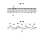
- 3A and 3B are diagrams schematically showing a surface portion and the like of the catalyst carrier of the NO x storage catalyst.
- 4A and 4B are diagrams for explaining the oxidation-reduction reaction in the NO x storage catalyst.
- FIG. 5 is a diagram showing NO x release control.
- FIG. 6 is a diagram showing a map of the exhausted NO x amount NOXA.
- FIG. 7 is a graph showing the NO x purification rate.
- FIG. 8 is a diagram showing a change in the amount of desorbed ammonia based on a difference in the way of ammonia adsorption.
- FIG. 9A and 9B are diagrams for explaining how ammonia is adsorbed.
- FIG. 10 is a graph showing the relationship between the change in air-fuel ratio and the amount of ammonia generated.
- FIG. 11 is a diagram showing the relationship between the change in the air-fuel ratio and the amount of ammonia generated.
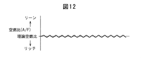
- FIG. 12 shows the feedback control of the air-fuel ratio in the combustion chamber to the stoichiometric air-fuel ratio.
- 13A and 13B are diagrams for explaining the oxidation-reduction reaction in the NO x storage catalyst.
- 14A and 14B are diagrams for explaining the NO x absorption ability and NO adsorption ability.
- 15A and 15B are diagrams for explaining the NO x absorption ability and NO adsorption ability.
- FIG. 16 is a time chart showing changes in the air-fuel ratio of the exhaust gas flowing into the three-way catalyst and the NO x storage catalyst.
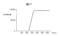
- FIG. 17 is a diagram showing the NO x purification rate.
- FIG. 18 is a diagram showing an operation region of the engine.
- FIG. 19 is a time chart showing changes in the fuel injection amount and the like during engine operation.
- FIG. 20 is a flowchart for performing engine operation control.
- FIG. 1 shows an overall view of a spark ignition type internal combustion engine.
- 1 is an engine body
- 2 is a cylinder block
- 3 is a cylinder head
- 4 is a piston
- 5 is a combustion chamber
- 6 is a spark plug
- 7 is an intake valve
- 8 is an intake port
- 9 is an exhaust valve
- Reference numeral 10 denotes an exhaust port.
- each cylinder has an electronically controlled fuel injection valve 11 for injecting fuel into the combustion chamber 2 and an electronically controlled fuel for injecting fuel into the intake port 8.
- a pair of fuel injection valves including the injection valves 12 is provided.
- the intake port 8 of each cylinder is connected to a surge tank 14 via an intake branch pipe 13, and the surge tank 14 is connected to an air cleaner 16 via an intake duct 15.
- an intake air amount detector 17 and a throttle valve 18 driven by an actuator 18a are arranged.
- the exhaust port 10 of each cylinder is connected to the inlet of the three-way catalyst 20 via the exhaust manifold 19, and the outlet of the three-way catalyst 20 is connected to the inlet of the NO x storage catalyst 22 via the exhaust pipe 21.
- the outlet of the NO x storage catalyst 22 is connected to the NO x selective reduction catalyst 23.
- the exhaust pipe 21 and the surge tank 14 are connected to each other via an exhaust gas recirculation (hereinafter referred to as EGR) passage 24.
- An electronically controlled EGR control valve 25 is disposed in the EGR passage 24, and a cooling device 26 for cooling the exhaust gas flowing in the EGR passage 24 is disposed around the EGR passage 24.
- the engine cooling water is guided into the cooling device 26, and the exhaust gas is cooled by the engine cooling water.
- the electronic control unit 30 is composed of a digital computer and includes a ROM (Read Only Memory) 32, a RAM (Random Access Memory) 33, a CPU (Microprocessor) 34, an input port 35 and an output port 36 connected to each other by a bidirectional bus 31. It comprises.
- An air-fuel ratio sensor 27 for detecting the air-fuel ratio of the exhaust gas discharged from the engine is attached upstream of the three-way catalyst 20, and the oxygen concentration in the exhaust gas is detected downstream of the three-way catalyst 20.
- an oxygen concentration sensor 28 is attached.
- Output signals of the air-fuel ratio sensor 27, the oxygen concentration sensor 28, and the intake air amount detector 17 are input to the input port 35 via corresponding AD converters 37, respectively.
- a load sensor 41 that generates an output voltage proportional to the depression amount L of the accelerator pedal 40 is connected to the accelerator pedal 40, and the output voltage of the load sensor 41 is input to the input port 35 via the corresponding AD converter 37. Is done. Further, a crank angle sensor 42 that generates an output pulse every time the crankshaft rotates, for example, 30 ° is connected to the input port 35. On the other hand, the output port 36 is connected to the spark plug 6, the fuel injection valves 11 and 12, the throttle valve driving actuator 18 a and the EGR control valve 25 via the corresponding drive circuit 38.
- FIG. 2 schematically shows the surface portion of the base 50 of the three-way catalyst 20.
- an upper coat layer 51 and a lower coat layer 52 are formed on the catalyst carrier 50 in a laminated form.
- the upper coat layer 51 is made of rhodium Rh and cerium Ce
- the lower coat layer 52 is made of platinum Pt and cerium Ce.
- the amount of cerium Ce contained in the upper coat layer 51 is smaller than the amount of cerium Ce contained in the lower coat layer 52.
- the upper coat layer 51 can contain zirconia Zr soot
- the lower coat layer 52 can contain palladium Pd soot.
- the three-way catalyst 20 is contained in the exhaust gas when combustion is performed in the combustion chamber 5 under the stoichiometric air-fuel ratio, that is, when the air-fuel ratio of the exhaust gas discharged from the engine is the stoichiometric air-fuel ratio. It has a function of simultaneously reducing harmful components HC, CO and NO x contained therein. Therefore, when combustion is performed in the combustion chamber 5 under the stoichiometric air-fuel ratio, harmful components HC, CO and NO x contained in the exhaust gas are purified by the three-way catalyst 20.
- the air-fuel ratio of the exhaust gas discharged from the combustion chamber 5 becomes almost the stoichiometric air-fuel ratio.
- the injection amount from the fuel injection valves 11 and 12 is feedback controlled based on the detection signal of the air-fuel ratio sensor 27 so that the air-fuel ratio of the exhaust gas discharged from the combustion chamber 5 fluctuates around the stoichiometric air-fuel ratio. Is done.
- FIG. 3A schematically shows the surface portion of the base 55 of the NO x storage catalyst 22.
- the coat layer 56 is formed on the base 55 also in the NO x storage catalyst 22.
- the coat layer 56 is made of, for example, an aggregate of powder
- FIG. 3B shows an enlarged view of the powder.
- noble metal catalysts 61 and 62 are supported on a catalyst carrier 60 made of alumina, for example, of this powder, and further, such as potassium K, sodium Na, and cesium Cs are supported on the catalyst carrier 60.
- alkali metal barium Ba
- alkaline earth metals such as calcium Ca, rare earth and silver Ag, such as lanthanides, copper Cu, iron Fe, at least selected from a metal which can donate electrons to NO x, such as iridium Ir
- a basic layer 63 including one is formed.
- the noble metal catalyst 61 is made of platinum Pt and the noble metal catalyst 62 is made of rhodium Rh.
- any of the noble metal catalysts 61 and 62 can be made of platinum Pt.
- palladium Pd can be supported on the catalyst carrier 60, or palladium Pd can be supported instead of rhodium Rh. That is, the noble metal catalysts 61 and 62 supported on the catalyst carrier 60 are composed of at least one of platinum Pt, rhodium Rh and palladium Pd.
- FIGS. 4A and 4B shows an enlarged view of FIG. 3B.
- the catalyst is oxidized on platinum Pt 61 to become NO 2 , and then absorbed into the basic layer 63 and diffused into the basic layer 63 in the form of nitrate ions NO 3 ⁇ to become nitrates.
- NO x in the exhaust gas is absorbed in the basic layer 63 in the form of nitrate.
- NO 2 is generated on the surface of platinum Pt 61, and NO x is absorbed in the basic layer 63 and nitrate is generated unless the NO x absorption capacity of the basic layer 63 is saturated.
- the oxygen concentration in the exhaust gas flowing into the NO x storage catalyst 22 decreases, so that the reaction is in the reverse direction (NO 3 ⁇ ⁇ NO 2 ).
- the nitrate absorbed in the basic layer 63 is successively released as nitrate ions NO 3 ⁇ from the basic layer 63 in the form of NO 2 as shown in FIG. 4B.
- the released NO 2 is then reduced by the hydrocarbons HC and CO contained in the exhaust gas.
- the engine intake passage when the ratio of the supplied air and fuel into the combustion chamber 5 and the NO x storage catalyst 22 upstream of the exhaust passage (hydrocarbon) is referred to as the air-fuel ratio of the exhaust gas, the NO x storage catalyst 22,
- the air-fuel ratio of the exhaust gas flowing into the NO x storage catalyst 22 is lean, NO x is stored, and when the air-fuel ratio of the exhaust gas flowing into the NO x storage catalyst 22 becomes rich, the stored NO x is released. .
- NO x in the exhaust gas is stored in the NO x storage catalyst 22.
- the NO x storage capacity of the NO x storage catalyst 22 is saturated during that time, and as a result, the NO x storage catalyst 22 can store NO x. It will disappear. Therefore, temporarily rich air-fuel ratio in the combustion chamber 5 before the NO x storage capacity of the NO x storage catalyst 22 is saturated, thereby so that to release NO x from the NO x storage catalyst 22.
- Figure 5 shows the NO x releasing control from the NO x storage catalyst 22 used in the embodiment according to the present invention.
- the air-fuel ratio (A / F) at is temporarily made rich.
- the air-fuel ratio (A / F) in the combustion chamber 5 is made rich, that is, when the air-fuel ratio of the exhaust gas flowing into the NO x storage catalyst 22 is made rich, combustion is performed under the lean air-fuel ratio.
- the NO x storage catalyst 22 to the occluded NO x is reduced is released all at once from the NO x storage catalyst 22. As a result, NO x is purified.
- Occluded amount of NO x ⁇ NOX is calculated from the amount of NO x exhausted from the engine, for example. Is stored in advance in the ROM32 in the form of a map as shown in FIG. 6 as a function of the discharge amount of NO x NOXA is required load L and engine speed N which is discharged from the engine per unit time in this embodiment of the present invention, The occluded NO x amount ⁇ NOX is calculated from this exhausted NO x amount NOXA. In this case, the period during which the air-fuel ratio in the combustion chamber 5 is made rich is usually 1 minute or more.
- Figure 7 shows the NO x purification rate when so as to purify NO x by absorbing and releasing action of the NO x such, NO x storage catalyst 22 as shown in FIG.
- the horizontal axis in FIG. 7 indicates the catalyst temperature TC of the NO x storage catalyst 22.
- reduced catalyst temperature TC When it extremely high NO x purification rate is obtained catalyst temperature TC becomes a high temperature of at least 400 ° C. when the 300 ° C. of 400 ° C. the NO x purification rate To do. The reason why the the catalyst temperature TC becomes equal to or higher than 400 ° C. NO x purification rate is lowered, when the catalyst temperature TC becomes equal to or higher than 400 ° C.
- NO x becomes difficult occluded, also the form of NO 2 and nitrate is thermally decomposed This is because the NO x storage catalyst 22 is released. That is, as long as NO x is occluded in the form of nitrate, it is difficult to obtain a high NO x purification rate when the catalyst temperature TC is high.
- the air-fuel ratio of the exhaust gas flowing into the NO x storage catalyst 22 is NO x is released when it is rich from the NO x storage catalyst 22.
- NO x selective reduction catalyst 23 comprising ammonia from adsorbable zeolite downstream of the NO x storage catalyst 22 and is arranged, therefore, it occurs in the NO x storage catalyst 22
- the ammonia thus absorbed is adsorbed by the NO x selective reduction catalyst 23.
- NO x flowing out from the NO x storage catalyst 22 is reduced by the ammonia adsorbed on the NO x selective reduction catalyst 23. That is, in the present invention, when the air-fuel ratio of the exhaust gas flowing into the NO x storage catalyst 22 is maintained lean, NO x contained in the exhaust gas is stored in the NO x storage catalyst 22 and stored at this time. The NO x which has not been reduced is reduced by the ammonia adsorbed on the NO x selective reduction catalyst 23.
- drawing schematically illustrating de 8 shows the relationship between the temperature TB of the release amount of ammonia and the NO x selective reduction catalyst 23, and the structure of the NO x selective reduction catalyst 23 from the NO x selective reduction catalyst 23 A method of adsorbing ammonia will be described with reference to 9A and 9B.
- FIG. 8 shows a change in the amount of desorbed ammonia when the temperature TB of the NO x selective reduction catalyst 23 is gradually increased, and when the temperature TB of the NO x selective reduction catalyst 23 is increased from FIG. It can be seen that two peaks appear.
- One peak (L acid point) in FIG. 8 is due to desorption of ammonia adsorbed on a weak acid point called Lewis acid point (L acid point) as shown in FIG. 9A, and the other peak in FIG.
- the peak (B acid point) is due to the desorption of ammonia adsorbed on a strong acid point called a Bronsted acid point (B acid point) as shown in FIG. 9B.
- the ammonia adsorbed at the Bronsted acid point (B acid point), that is, the strong acid point as shown in FIG. 9B comes to NO x when the temperature TB of the NO x selective reduction catalyst 23 is relatively low. Is not desorbed and desorbed only when the temperature TB of the NO x selective reduction catalyst 23 becomes high.
- the temperature TB of the NO x selective reduction catalyst 23 does not rise to the temperature indicated by the B acid point in FIG. 8, and therefore, the Bronsted acid point (B acid point) as shown in FIG. 9B, that ammonia adsorbed on strong acid sites would not be used for the reduction of nO x. Therefore, in order to reduce NO x by the adsorbed ammonia, it is necessary to adsorb ammonia at a Lewis acid point (L acid point) as shown in FIG. 9A, that is, a weak acid point.
- L acid point Lewis acid point
- FIG. 10 shows the air-fuel ratio (A / F) in the combustion chamber 5 when NO x is purified using the NO x storage / release action to the NO x storage catalyst 22 during engine low load operation.
- the change and the amount of ammonia generated in the NO x storage catalyst 22 are shown.
- (A / F) b represents the base air-fuel ratio
- ⁇ (A / F) r represents the richness of the air-fuel ratio
- ⁇ T represents the rich cycle of the air-fuel ratio.
- NO x increases the unit time per the NO x storage catalyst 22.
- NO x is occluded in per unit time the NO x storage catalyst 22 is increased, the additional amount of fuel supplied to the air-fuel ratio in order to release the NO x per unit time to rich is increased.
- the amount of additional fuel supplied per unit time increases, the amount of ammonia produced per unit time in the NO x storage catalyst 22 increases. That is, as the engine load increases, the amount of ammonia produced per unit time in the NO x storage catalyst 22 increases.
- ammonia when ammonia reaches the NO x selective reduction catalyst 23, ammonia is adsorbed from a Lewis acid point (L acid point) that is easily adsorbed, that is, from a weak acid point, and when the amount adsorbed to the weak acid point is saturated, Bronsted is difficult to adsorb. Adsorption to an acid point (B acid point), that is, a strong acid point is started.
- L acid point Lewis acid point
- B acid point that is, a strong acid point
- FIG. 11 shows the change in the air-fuel ratio (A / F) in the combustion chamber 5 and the amount of ammonia generated in the NO x storage catalyst 22 at this time.
- (A / F) b represents the base air-fuel ratio
- ⁇ (A / F) r represents the richness of the air-fuel ratio
- ⁇ T represents the air-fuel ratio rich cycle.
- the base air-fuel ratio (A / F) b is made lower than in the engine low-load operation shown in FIG. / F) r is reduced, and the air-fuel ratio rich cycle ⁇ T is shortened. That is, when the amount of additional fuel injection when the air-fuel ratio is made rich is increased, the amount of reducing agent such as hydrocarbon is also increased, so that the amount of ammonia generated tends to increase. Therefore, in order to reduce the additional fuel injection amount when the air-fuel ratio is made rich, as shown in FIG. 11, the base air-fuel ratio (A / F) b is lowered and the air-fuel ratio rich degree ⁇ (A / F F) r is decreased and the air-fuel ratio rich cycle ⁇ T is shortened.
- NO x storage catalyst 22 is disposed, NO x selective reduction catalyst 23 is disposed in the engine exhaust passage downstream of NO x storage catalyst 22, and when the air-fuel ratio of the inflowing exhaust gas is made rich, NO x exhaust purification system of an internal combustion engine so as to reduce the NO x in the exhaust gas by ammonia adsorbed on the NO x selective reduction catalyst 23 together with the adsorbed ammonia produced in storage catalyst 22 to the NO x selective reduction catalyst 23
- the engine is under low load operation, combustion is performed in the combustion chamber 5 with the base air-fuel ratio lean, and when the NO x storage catalyst 22 should release NO x , the air-fuel ratio in the combustion chamber 5 is reduced.
- the base When the engine load becomes higher than during low engine load operation, the base is set so that the amount of ammonia produced per unit time when the air-fuel ratio is made rich is lower than during low engine load operation.
- the air-fuel ratio is reduced, the degree of richness of the air-fuel ratio is reduced, and the cycle for enriching the air-fuel ratio is shortened.
- FIG. 12 shows changes in the air-fuel ratio in the combustion chamber 5 when the air-fuel ratio in the combustion chamber 5 is feedback-controlled to the stoichiometric air-fuel ratio.
- the base air-fuel ratio is reduced, the degree of richness of the air-fuel ratio is reduced, and the cycle for enriching the air-fuel ratio is shortened as compared with the low engine load operation.
- Heading way but improves the purification action of the NO x by adsorbing ammonia in the NO x selective reduction catalyst 23, at the same time, that the NO x purification rate in the NO x storage catalyst 22 is improved by the present inventors It was done.
- the new NO x purification method found by the present inventors is based on the NO adsorption action of the NO x storage catalyst 22.
- FIGS. 13A and 13B show an enlarged view of FIG. 3B, that is, a surface portion of the catalyst carrier 60 of the NO x storage catalyst 22.
- FIG. 13A shows the time when combustion is performed under a lean air-fuel ratio
- FIG. 13B shows the time when the air-fuel ratio in the combustion chamber 5 is made rich.
- NO x contained in the exhaust gas is absorbed into the basic layer 63 as described above.
- Part of the NO contained in the exhaust gas is dissociated and adsorbed on the surface of platinum Pt 61 as shown in FIG. 13A.
- the adsorption amount of NO on the surface of the platinum Pt 61 increases with the passage of time, and therefore, the adsorption amount of NO on the NO x storage catalyst 22 increases with the passage of time.
- NO x contained in the exhaust gas is NO. is absorbed in the x storage catalyst 22, as on the other hand shown in FIG. 13A, NO contained in the exhaust gas is adsorbed on the NO x storage catalyst 22. That is, at this time, NO x contained in the exhaust gas is stored in the NO x storage catalyst 22.
- the air-fuel ratio is made rich in the combustion chamber 5
- the NO x storage catalyst 22 to the absorption or adsorption once was NO x, i.e. NO x NO x that was stored in the storage catalyst 22 is the NO x storage It will be released from the catalyst 22.
- FIG. 14A shows the NO x absorption ability and the NO adsorption ability when NO x is purified using the NO x storage / release action to the NO x storage catalyst 22, as shown in FIG.
- the vertical axis in FIG. 14A shows the storage capacity of the NO x which is the sum of the NO x absorption ability and NO adsorption capacity
- the horizontal axis represents the temperature TC of the NO x storage catalyst 22.
- Figure 14A when lower than the temperature TC approximately 400 ° C.
- NO x absorption capacity and NO adsorption capacity is constant,
- storage capacity of the NO x which is the sum of the absorption capacity and NO adsorption capacity NO x also becomes constant regardless of the temperature TC of the NO x storage catalyst 22.
- the amount of NO quantity of NO contained in the exhaust gas is adsorbed on the surface of The more the more the platinum Pt 61 as compared to the amount of O 2 becomes more than the amount of O 2, on the contrary As the amount of O 2 contained in the exhaust gas increases as compared with the amount of NO, the amount of NO adsorbed on the surface of platinum Pt 61 decreases as compared with the amount of O 2 . Therefore, the NO adsorption capacity of the NO x storage catalyst 22 decreases as the oxygen concentration in the exhaust gas increases, as shown in FIG. 15A.
- FIG. 15B shows the NO x absorption capacity of the NO x storage catalyst 22 increases as the oxygen concentration in the exhaust gas increases.
- region X as shown in FIG. 5, a lean air-fuel ratio in the case that purifies NO x by using insertion releasing action of the NO x into the NO x storage catalyst 22 It shows when combustion is taking place. At this time, it can be seen that the NO adsorption capacity is low and the NO x absorption capacity is high.
- FIG. 14A described above shows the NO adsorption capacity and the NO x absorption capacity at this time.
- the oxygen concentration in the exhaust gas may be decreased.
- NO x absorption ability is reduced.
- FIG. 14B shows the NO x absorption ability and NO adsorption ability when the oxygen concentration in the exhaust gas is lowered to the region Y in FIGS. 15A and 15B.
- FIG. 16 shows the change in the air-fuel ratio (A / F) in the combustion chamber 5 when the NO x is purified by utilizing the NO adsorption action and the NO x storage catalyst 22 as shown in FIG. 2 shows the change in the air-fuel ratio (A / F) in of the exhaust gas flowing into the engine.
- the air-fuel ratio (A / F) in the combustion chamber 5 is made rich, the oxygen stored in the three-way catalyst 20 is released and maintained at the stoichiometric air-fuel ratio for a time t1, Thereby, HC, CO and NO x are simultaneously reduced. During this time, as shown in FIG.
- the air-fuel ratio (A / F) in of the exhaust gas flowing into the NO x storage catalyst 22 is maintained at the stoichiometric air-fuel ratio.
- the air-fuel ratio (A / F) in of the exhaust gas flowing into the NO x storage catalyst 22 becomes rich during the time t2.
- NO dissociated and adsorbed on the surface of platinum Pt 61 becomes N 2 on the one hand and a reducing intermediate NCO on the other hand.
- the reducing intermediate NCO continues to be held or adsorbed on the surface of the basic layer 63 for a while after the generation.
- the base air-fuel ratio is made smaller, the degree of richness of the air-fuel ratio is made smaller, and the air-fuel ratio is made richer than when the engine load is low.
- the purification action of the NO x utilizing the adsorption NO, the and purification action of the NO x using the oxygen storage function of a three-way catalyst 20 and adsorbed on the NO x selective reduction catalyst 23 Three purification actions are performed, including NO x purification action by ammonia.
- the NO x purification rate at this time is shown in FIG. As shown in FIG. 17, in this case, it is understood that the NO x purification rate does not decrease even when the temperature TC of the NO x storage catalyst 22 increases and reaches a high temperature of 400 ° C. or higher.
- the engine low load operation region I on the engine low load operation side, the engine high load operation region III on the engine high load operation side, and the engine low load operation region I Further, an engine middle load operation region II located between the engine high load operation region III is preset.
- shaft L of FIG. 18 has shown the required load
- the horizontal axis N has shown the engine speed.
- the engine low load operating region I as shown in FIG. 10
- the NO x purification action is performed in which NO x is purified by utilizing the NO adsorption action.
- the air-fuel ratio in the combustion chamber 5 is feedback-controlled to the stoichiometric air-fuel ratio.
- the three-way catalyst 20 is disposed in the engine exhaust passage upstream of the NO x storage catalyst 22, and the engine operating range is defined as a predetermined engine low load operating range I on the engine low load operating side.
- combustion is performed in the combustion chamber 5 while the base air-fuel ratio is lean, and when the NO x storage catalyst 22 should release NO x , the air-fuel ratio in the combustion chamber 5 Is rich, the air-fuel ratio in the combustion chamber 5 is feedback-controlled to the stoichiometric air-fuel ratio in a predetermined engine high load operation region III, and the air-fuel ratio is made rich in a predetermined engine medium load operation region II.
- the base air-fuel ratio in the engine medium load operation region II is an intermediate value between the base air fuel ratio and the stoichiometric air fuel ratio in the engine low load operation region I.
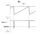
- FIG. 19 shows changes in the fuel injection amount into the combustion chamber 5, changes in the air-fuel ratio (A / F) in the combustion chamber 5, and changes in the stored NO x amount ⁇ NOX.
- MAXI represents the first allowable NO x storage amount
- MAX II represents the second allowable NO x storage amount.
- the second allowable NO x storage amount MAXII is set to a smaller value than the first allowable NO x storage amount MAXI.
- the air-fuel ratio in the combustion chamber 5 is temporarily made rich.
- the temperature of the NO x storage catalyst 22 is high, so that the NO x storage catalyst 22 hardly absorbs NO x , and most of the NO x is composed of adsorbed NO. Therefore, in other words, the NO adsorption amount adsorbed by the NO x storage catalyst 22 is calculated, and the NO adsorption amount ⁇ NOX is calculated when the engine is operating in the engine middle load operation region II.
- the predetermined allowable NO adsorption amount MAXII is exceeded, the air-fuel ratio (A / F) in the combustion chamber 5 is made rich.
- the NO x storage amount ⁇ NOX that stored in the NO x storage catalyst 22 are calculated, when the operation of the engine is performed in the engine low load operating region I, the NO x storage When the amount ⁇ NOX exceeds the predetermined first allowable NO x storage amount MAXI, the air-fuel ratio (A / F) in the combustion chamber 5 is made rich, and the engine is operated in the engine middle load operation region II.
- the air-fuel ratio (A / F) in the combustion chamber 5 is made rich, and the second The allowable NO x storage amount MAXII is a smaller value than the first allowable NO x storage amount MAXI.
- the injection amounts from the fuel injection valves 11 and 12 are feedback-controlled based on the output signal of the air-fuel ratio sensor 27 so that the air-fuel ratio in the combustion chamber 5 becomes the stoichiometric air-fuel ratio. .
- harmful components HC, CO and NO x contained in the exhaust gas are simultaneously purified in the three-way catalyst 20.
- FIG. 20 shows an operation control routine. This routine is executed by interruption every predetermined time.
- step 80 it is judged if the engine operating state is an engine high load operation region III shown in FIG.
- step 81 the discharge amount of NO x NOXA per unit time from the map shown in FIG. 6 is calculated.
- occluded amount of NO x ⁇ NOX is calculated by adding the discharge amount of NO x NOXA to ⁇ NOX step 82.
- step 83 it is judged if the engine operating state is an engine low load operating region I shown in FIG. When the engine operating state is in the engine low load operation region I shown in FIG.
- step 84 the NO x storage amount ⁇ NOX is discriminated whether or not more than the first allowable the NO x storage amount MAXI is, when the NO x storage amount ⁇ NOX has not exceeded the first tolerance the NO x storage amount MAXI, the step Proceeding to 85, the air-fuel ratio in the combustion chamber 5 is set to a lean air-fuel ratio that is predetermined according to the operating state of the engine. At this time, combustion is performed with the base air-fuel ratio lean.
- step 86 the routine proceeds to step 86, where the air-fuel ratio in the combustion chamber 5 becomes temporarily rich. ⁇ NOX is cleared. At this time, NO x NO x that was stored in the storage catalyst 22 is released from the NO x storage catalyst 22.
- step 83 when it is determined in step 83 that the engine operating state is not the engine low load operating region I shown in FIG. 18, that is, the engine operating state is the engine medium load operating region II shown in FIG.
- the routine proceeds to step 87, where it is determined whether or not the engine operating state has shifted from the engine low load operation region I to the engine middle load operation region II.
- step 88 the routine proceeds to step 88 where the air-fuel ratio in the combustion chamber 5 is temporarily made rich.
- the routine proceeds to step 89.
- step 89 it is determined whether or not the NO x selective reduction catalyst 23 has deteriorated. In this case, for example, when the travel distance of the vehicle exceeds a predetermined distance, it is determined that the NO x selective reduction catalyst 23 has deteriorated. When it is determined at step 89 that the NO x selective reduction catalyst 23 has not deteriorated, the routine proceeds to step 90, where it is determined whether or not the NO x storage amount ⁇ NOX exceeds the second allowable NO x storage amount MAXII. .
- the routine proceeds to step 91, where the air-fuel ratio in the combustion chamber 5 is set to a lean air space that is predetermined according to the operating state of the engine.
- the fuel ratio is set.
- combustion is performed with the base air-fuel ratio lean. Note that the base air-fuel ratio at this time is smaller than the base air-fuel ratio in the engine low load operation region I.
- step 90 when it is determined in step 90 that the NO x storage amount ⁇ NOX exceeds the second allowable NO x storage amount MAXII, the routine proceeds to step 92, where the air-fuel ratio in the combustion chamber 5 is temporarily rich. ⁇ NOX is cleared. At this time, NO x NO x that was stored in the storage catalyst 22 is released from the NO x storage catalyst 22.
- step 89 when the NO x selective reduction catalyst 23 is judged to have deteriorated in step 89, it is impossible to perform the purification action of the NO x using the longer adsorption of ammonia in the NO x selective reduction catalyst 23. Accordingly, at this time, the routine proceeds to step 93 where the air-fuel ratio in the combustion chamber 5 is feedback-controlled to the stoichiometric air-fuel ratio.
- step 80 when it is determined in step 80 that the engine operating state is the engine high load operating region III shown in FIG. 18, the routine proceeds to step 94, where the engine operating state is now changed from the engine medium load operating region II. It is determined whether or not the engine has shifted to the high engine load operation region III. Now, when the engine operating state shifts from the engine middle load operation region II to the engine high load operation region III, the routine proceeds to step 95 where the air-fuel ratio in the combustion chamber 5 is temporarily made rich. On the other hand, when the engine operating state has already shifted from the engine middle load operation region II to the engine high load operation region III, the routine proceeds to step 96. In step 96, the air-fuel ratio in the combustion chamber 5 is feedback-controlled to the stoichiometric air-fuel ratio.
- combustion chamber 6 spark plugs 11 and 12 fuel injection valve 14 surge tank 19 exhaust manifold 20 a three-way catalyst 22 NO x storage catalyst 23 NO x selective reduction catalyst
Landscapes
- Engineering & Computer Science (AREA)
- Chemical & Material Sciences (AREA)
- Combustion & Propulsion (AREA)
- Mechanical Engineering (AREA)
- General Engineering & Computer Science (AREA)
- Chemical Kinetics & Catalysis (AREA)
- Health & Medical Sciences (AREA)
- Toxicology (AREA)
- Exhaust Gas After Treatment (AREA)
- Exhaust Gas Treatment By Means Of Catalyst (AREA)
- Catalysts (AREA)
- Electrical Control Of Air Or Fuel Supplied To Internal-Combustion Engine (AREA)
Abstract
Priority Applications (5)
| Application Number | Priority Date | Filing Date | Title |
|---|---|---|---|
| JP2013552035A JP5664801B2 (ja) | 2012-08-28 | 2012-08-28 | 火花点火式内燃機関の排気浄化装置 |
| PCT/JP2012/071705 WO2014033838A1 (fr) | 2012-08-28 | 2012-08-28 | Dispositif de purification de gaz d'échappement pour moteur à combustion interne à allumage commandé |
| US14/234,015 US9494097B2 (en) | 2012-08-28 | 2012-08-28 | Exhaust purification system of spark ignition type internal combustion engine |
| CN201280036951.3A CN103764961B (zh) | 2012-08-28 | 2012-08-28 | 火花点火式内燃机的排气净化装置 |
| EP12881142.9A EP2740911B1 (fr) | 2012-08-28 | 2012-08-28 | Dispositif de purification de gaz d'échappement pour un moteur à combustion interne à allumage commandé |
Applications Claiming Priority (1)
| Application Number | Priority Date | Filing Date | Title |
|---|---|---|---|
| PCT/JP2012/071705 WO2014033838A1 (fr) | 2012-08-28 | 2012-08-28 | Dispositif de purification de gaz d'échappement pour moteur à combustion interne à allumage commandé |
Publications (1)
| Publication Number | Publication Date |
|---|---|
| WO2014033838A1 true WO2014033838A1 (fr) | 2014-03-06 |
Family
ID=50182688
Family Applications (1)
| Application Number | Title | Priority Date | Filing Date |
|---|---|---|---|
| PCT/JP2012/071705 WO2014033838A1 (fr) | 2012-08-28 | 2012-08-28 | Dispositif de purification de gaz d'échappement pour moteur à combustion interne à allumage commandé |
Country Status (5)
| Country | Link |
|---|---|
| US (1) | US9494097B2 (fr) |
| EP (1) | EP2740911B1 (fr) |
| JP (1) | JP5664801B2 (fr) |
| CN (1) | CN103764961B (fr) |
| WO (1) | WO2014033838A1 (fr) |
Cited By (2)
| Publication number | Priority date | Publication date | Assignee | Title |
|---|---|---|---|---|
| JP2017031960A (ja) * | 2015-08-06 | 2017-02-09 | トヨタ自動車株式会社 | 内燃機関の排気浄化装置 |
| JP2018009487A (ja) * | 2016-07-12 | 2018-01-18 | マツダ株式会社 | エンジンの排気浄化装置 |
Families Citing this family (4)
| Publication number | Priority date | Publication date | Assignee | Title |
|---|---|---|---|---|
| WO2014122728A1 (fr) * | 2013-02-05 | 2014-08-14 | トヨタ自動車株式会社 | Épurateur de gaz d'échappement pour moteur à combustion interne |
| US9494072B2 (en) * | 2013-02-20 | 2016-11-15 | Toyota Jidosha Kabushiki Kaisha | Exhaust purification system of internal combustion engine |
| FR3025557B1 (fr) * | 2014-09-04 | 2016-11-18 | Peugeot Citroen Automobiles Sa | Vehicule automobile a dispositif de depollution ameliore |
| JP6601449B2 (ja) * | 2017-04-04 | 2019-11-06 | トヨタ自動車株式会社 | 内燃機関の排気浄化装置 |
Citations (4)
| Publication number | Priority date | Publication date | Assignee | Title |
|---|---|---|---|---|
| JP2002364415A (ja) * | 2001-06-07 | 2002-12-18 | Mazda Motor Corp | エンジンの排気浄化装置 |
| JP2008286102A (ja) | 2007-05-17 | 2008-11-27 | Isuzu Motors Ltd | NOx浄化システムの制御方法及びNOx浄化システム |
| WO2011142028A1 (fr) * | 2010-05-14 | 2011-11-17 | トヨタ自動車株式会社 | Système de purification des gaz d'échappement pour moteur à combustion interne |
| JP4868096B2 (ja) * | 2009-09-03 | 2012-02-01 | トヨタ自動車株式会社 | 内燃機関の排気浄化装置 |
Family Cites Families (19)
| Publication number | Priority date | Publication date | Assignee | Title |
|---|---|---|---|---|
| JPH06190245A (ja) | 1992-12-28 | 1994-07-12 | Mazda Motor Corp | 排気ガス浄化用触媒構造 |
| SE519908C2 (sv) * | 1998-03-20 | 2003-04-22 | Volvo Car Corp | Förfarande och anordning för styrning av förbränningsmotor |
| DE19961165A1 (de) * | 1999-12-17 | 2001-08-02 | Volkswagen Ag | Verfahren zur Entschwefelung eines in einem Abgaskanal einer Verbrennungskraftmaschine angeordneten NO¶x¶-Speicherkatalysators |
| DE10007048A1 (de) * | 2000-02-17 | 2001-08-23 | Volkswagen Ag | Vorrichtung und Verfahren zur Ermittlung einer Regenerationsnotwendigkeit eines NO¶x¶-Speicherkatalysators |
| US6928808B2 (en) * | 2000-02-17 | 2005-08-16 | Volkswagen Atkiengesellschaft | Device and method for controlling the nox regeneration of a nox storage catalyst |
| JP3858554B2 (ja) * | 2000-02-23 | 2006-12-13 | 株式会社日立製作所 | エンジン排気浄化装置 |
| JP4288942B2 (ja) * | 2002-12-20 | 2009-07-01 | トヨタ自動車株式会社 | 内燃機関の排気浄化装置 |
| US6732507B1 (en) * | 2002-12-30 | 2004-05-11 | Southwest Research Institute | NOx aftertreatment system and method for internal combustion engines |
| US7401462B2 (en) * | 2004-03-30 | 2008-07-22 | General Motors Corporation | Control strategy for lean NOx trap regeneration |
| JP4572709B2 (ja) * | 2005-03-18 | 2010-11-04 | トヨタ自動車株式会社 | 内燃機関の排気浄化システム |
| JP3901194B2 (ja) * | 2005-04-21 | 2007-04-04 | いすゞ自動車株式会社 | 排気ガス浄化方法及び排気ガス浄化システム |
| US20080314022A1 (en) * | 2007-06-19 | 2008-12-25 | Eaton Corporation | Strategy for scheduling LNT regeneration |
| DE102009010711A1 (de) * | 2009-02-27 | 2010-09-30 | Umicore Ag & Co. Kg | Stickoxid-Speicherkatalysator zum Einsatz im Kraftfahrzeug in motornaher Position |
| JP5163809B2 (ja) * | 2009-04-06 | 2013-03-13 | トヨタ自動車株式会社 | 内燃機関の排気浄化装置 |
| US8769934B2 (en) * | 2009-10-20 | 2014-07-08 | Toyota Jidosha Kabushiki Kaisha | Exhaust purifying system for internal combustion engine |
| CN102667082B (zh) * | 2009-11-18 | 2014-09-24 | 丰田自动车株式会社 | 内燃机的排气净化系统 |
| US8677734B2 (en) | 2010-04-19 | 2014-03-25 | GM Global Technology Operations LLC | Method of producing ammonia effective to control aftertreatment conditions of NOx emissions |
| WO2012014330A1 (fr) * | 2010-07-28 | 2012-02-02 | トヨタ自動車株式会社 | Appareil d'épuration de gaz d'échappement pour moteur à combustion interne |
| US8701390B2 (en) * | 2010-11-23 | 2014-04-22 | International Engine Intellectual Property Company, Llc | Adaptive control strategy |
-
2012
- 2012-08-28 US US14/234,015 patent/US9494097B2/en active Active
- 2012-08-28 WO PCT/JP2012/071705 patent/WO2014033838A1/fr active Application Filing
- 2012-08-28 JP JP2013552035A patent/JP5664801B2/ja active Active
- 2012-08-28 CN CN201280036951.3A patent/CN103764961B/zh not_active Expired - Fee Related
- 2012-08-28 EP EP12881142.9A patent/EP2740911B1/fr active Active
Patent Citations (4)
| Publication number | Priority date | Publication date | Assignee | Title |
|---|---|---|---|---|
| JP2002364415A (ja) * | 2001-06-07 | 2002-12-18 | Mazda Motor Corp | エンジンの排気浄化装置 |
| JP2008286102A (ja) | 2007-05-17 | 2008-11-27 | Isuzu Motors Ltd | NOx浄化システムの制御方法及びNOx浄化システム |
| JP4868096B2 (ja) * | 2009-09-03 | 2012-02-01 | トヨタ自動車株式会社 | 内燃機関の排気浄化装置 |
| WO2011142028A1 (fr) * | 2010-05-14 | 2011-11-17 | トヨタ自動車株式会社 | Système de purification des gaz d'échappement pour moteur à combustion interne |
Cited By (2)
| Publication number | Priority date | Publication date | Assignee | Title |
|---|---|---|---|---|
| JP2017031960A (ja) * | 2015-08-06 | 2017-02-09 | トヨタ自動車株式会社 | 内燃機関の排気浄化装置 |
| JP2018009487A (ja) * | 2016-07-12 | 2018-01-18 | マツダ株式会社 | エンジンの排気浄化装置 |
Also Published As
| Publication number | Publication date |
|---|---|
| CN103764961B (zh) | 2016-01-13 |
| EP2740911A4 (fr) | 2017-01-04 |
| CN103764961A (zh) | 2014-04-30 |
| US9494097B2 (en) | 2016-11-15 |
| EP2740911B1 (fr) | 2021-03-10 |
| JPWO2014033838A1 (ja) | 2016-08-08 |
| EP2740911A1 (fr) | 2014-06-11 |
| US20150204261A1 (en) | 2015-07-23 |
| JP5664801B2 (ja) | 2015-02-04 |
Similar Documents
| Publication | Publication Date | Title |
|---|---|---|
| KR101339523B1 (ko) | 내연 기관의 배기 정화 장치 | |
| JP4868097B1 (ja) | 内燃機関の排気浄化装置 | |
| WO2011114540A1 (fr) | Dispositif de purification des gaz d'échappement pour moteur à combustion interne | |
| WO2012029189A1 (fr) | Dispositif de purification des gaz d'échappement pour un moteur à combustion interne | |
| JP5664801B2 (ja) | 火花点火式内燃機関の排気浄化装置 | |
| WO2009019951A1 (fr) | Appareil de purification de gaz d'échappement pour moteur à combustion interne | |
| JP6015760B2 (ja) | 火花点火式内燃機関の排気浄化装置 | |
| JP4868096B2 (ja) | 内燃機関の排気浄化装置 | |
| JP5748005B2 (ja) | 内燃機関の排気浄化装置 | |
| WO2012029190A1 (fr) | Dispositif de purification de gaz d'échappement de moteur à combustion interne | |
| JP5673861B2 (ja) | 内燃機関の排気浄化装置 | |
| WO2012053117A1 (fr) | Dispositif d'épuration des gaz d'échappement pour moteur à combustion interne | |
| JP5835488B2 (ja) | 内燃機関の排気浄化装置 | |
| EP3030763B1 (fr) | Dispositif de purification des gaz d'echappement pour un moteur a combustion interne | |
| WO2012111171A1 (fr) | Dispositif de purification de gaz d'échappement pour moteur à combustion interne | |
| WO2012014330A1 (fr) | Appareil d'épuration de gaz d'échappement pour moteur à combustion interne | |
| US20120042636A1 (en) | Exhaust purification system of internal combustion engine | |
| US9103259B2 (en) | Exhaust purification system of internal combustion engine | |
| WO2014024311A1 (fr) | Dispositif de purification de gaz d'échappement pour moteur à combustion interne et à allumage par étincelle | |
| JP2011231755A (ja) | 内燃機関の排気浄化装置 | |
| JP5168410B2 (ja) | 内燃機関の排気浄化装置 | |
| EP2503120B1 (fr) | Procédé de purification des nox d'un sytème de purification de gaz d'échappement pour moteur à combustion interne | |
| JP5741643B2 (ja) | 内燃機関の排気浄化装置 |
Legal Events
| Date | Code | Title | Description |
|---|---|---|---|
| ENP | Entry into the national phase |
Ref document number: 2013552035 Country of ref document: JP Kind code of ref document: A |
|
| WWE | Wipo information: entry into national phase |
Ref document number: 14234015 Country of ref document: US |
|
| WWE | Wipo information: entry into national phase |
Ref document number: 2012881142 Country of ref document: EP |
|
| 121 | Ep: the epo has been informed by wipo that ep was designated in this application |
Ref document number: 12881142 Country of ref document: EP Kind code of ref document: A1 |
|
| NENP | Non-entry into the national phase |
Ref country code: DE |