WO2014027657A1 - チタン薄板 - Google Patents
チタン薄板 Download PDFInfo
- Publication number
- WO2014027657A1 WO2014027657A1 PCT/JP2013/071869 JP2013071869W WO2014027657A1 WO 2014027657 A1 WO2014027657 A1 WO 2014027657A1 JP 2013071869 W JP2013071869 W JP 2013071869W WO 2014027657 A1 WO2014027657 A1 WO 2014027657A1
- Authority
- WO
- WIPO (PCT)
- Prior art keywords
- thickness
- less
- titanium
- elongation
- thin plate
- Prior art date
- Legal status (The legal status is an assumption and is not a legal conclusion. Google has not performed a legal analysis and makes no representation as to the accuracy of the status listed.)
- Ceased
Links
Images

Classifications
-
- C—CHEMISTRY; METALLURGY
- C22—METALLURGY; FERROUS OR NON-FERROUS ALLOYS; TREATMENT OF ALLOYS OR NON-FERROUS METALS
- C22C—ALLOYS
- C22C14/00—Alloys based on titanium
-
- C—CHEMISTRY; METALLURGY
- C22—METALLURGY; FERROUS OR NON-FERROUS ALLOYS; TREATMENT OF ALLOYS OR NON-FERROUS METALS
- C22F—CHANGING THE PHYSICAL STRUCTURE OF NON-FERROUS METALS AND NON-FERROUS ALLOYS
- C22F1/00—Changing the physical structure of non-ferrous metals or alloys by heat treatment or by hot or cold working
- C22F1/16—Changing the physical structure of non-ferrous metals or alloys by heat treatment or by hot or cold working of other metals or alloys based thereon
- C22F1/18—High-melting or refractory metals or alloys based thereon
- C22F1/183—High-melting or refractory metals or alloys based thereon of titanium or alloys based thereon
-
- Y—GENERAL TAGGING OF NEW TECHNOLOGICAL DEVELOPMENTS; GENERAL TAGGING OF CROSS-SECTIONAL TECHNOLOGIES SPANNING OVER SEVERAL SECTIONS OF THE IPC; TECHNICAL SUBJECTS COVERED BY FORMER USPC CROSS-REFERENCE ART COLLECTIONS [XRACs] AND DIGESTS
- Y10—TECHNICAL SUBJECTS COVERED BY FORMER USPC
- Y10T—TECHNICAL SUBJECTS COVERED BY FORMER US CLASSIFICATION
- Y10T428/00—Stock material or miscellaneous articles
- Y10T428/12—All metal or with adjacent metals
- Y10T428/12993—Surface feature [e.g., rough, mirror]
Definitions
- the present invention relates to a titanium thin plate, and more particularly to a high-strength titanium thin plate having excellent workability and high surface hardness and excellent workability that can be suitably used for speaker diaphragms and the like.
- Titanium materials have high specific strength and excellent corrosion resistance, and are widely used as materials for chemical plants, construction, and many other industrial materials, as well as for consumer products such as camera bodies, watches and sports equipment. Used for applications.
- Titanium materials are no exception and are often required to have not only excellent workability but also high strength. However, in general, workability decreases when the strength is increased. For titanium materials, attempts are made to optimize the balance between strength and workability by controlling the oxygen content, iron content, crystal grain size, and the like. I have been.
- Patent Document 1 the ductility of a titanium plate is increased by increasing the Fe content (Fe: 0.1 to 0.6 mass%) while keeping the O (oxygen) content in the titanium material at a predetermined value.
- a titanium plate is disclosed in which the strength is improved while suppressing the decrease in the thickness, and the formability is improved so that the average particle size is 10 ⁇ m or less.
- Patent Document 2 discloses a Ti plate material having good forming workability in which the Fe content is 300 ppm or more and the [Fe + O + N + H] content is 1500 ppm or less, and the amount of nitrogen and hydrogen is limited in addition to the amount of iron and oxygen. ing.
- Patent Document 3 the amount of iron, the amount of oxygen, and further the amount of nickel and chromium are specified within a predetermined range so that good formability can be maintained even when an inexpensive raw material with low purity is used.
- a method for producing a pure titanium plate having an average particle size of 20 to 80 ⁇ m is disclosed.
- Patent Document 4 discloses a method for producing a titanium foil having excellent formability. According to this technique, titanium foil having a thickness of 25 ⁇ m is rolled under predetermined rolling conditions, and the crystal grain size is determined according to ASTM No. It is said that a good Erichsen value is ensured by controlling so as to be 12 to 14.
- a titanium foil having a thickness of 0.2 mm or less is required to have good shape retention after molding.
- good shape retention can be ensured, but on the other hand, there is a problem that good workability cannot be obtained.
- the part which received the big process improves intensity
- Patent Document 5 discloses a technique of performing electrolytic pickling after forming a layer containing titanium carbide and / or nitride as an inner surface layer by bright annealing or vacuum annealing. This technology prevents adhesion of the titanium base material to the mold by suppressing contact between the soft titanium base material and the mold, and at the same time forms an oxide layer with excellent lubricity during pressing on the titanium surface. Is. According to this technique, titanium carbide and / or nitride can be prevented from coming into contact with the mold, and wear of the mold can be prevented.
- titanium foil having a thickness of 0.2 mm or less is rarely subjected to severe processing as disclosed in Patent Document 5.
- processing of speaker diaphragms is often molded into a dome shape by applying internal pressure, and there is less contact with the mold during processing compared to molding with a general thin plate press, and surface lubrication of the material itself Sex doesn't matter so much. Therefore, even if the technique described in Patent Document 5 is applied, the workability improvement effect due to the lubricating effect of the oxide is not exhibited.
- this technique performs electrolytic pickling, a decrease in yield cannot be overlooked when this technique is applied to a titanium foil material having a thickness of 0.2 mm or less.
- Japanese Patent No. 4605514 Japanese Unexamined Patent Publication No. Sho 63-103043 Japanese Patent No. 3228134 Japanese Patent No. 2616181 Japanese Unexamined Patent Publication No. 2009-97060
- the present invention has been made in view of such circumstances, and an object of the present invention is to provide a titanium thin plate having a thickness of 0.2 mm or less and excellent in shape retention and workability.
- the present inventors pay attention to the hardness of the surface of the titanium foil, and if the surface is hard and the inside is softer than the surface, it is possible to achieve both shape retention and workability. Therefore, we investigated the methods for improving the workability and surface hardness of titanium thin plates.
- An effective means for improving the workability of titanium thin plates is to reduce the elements such as iron and oxygen. Although these elements are elements inevitably brought into production, it is necessary to limit them to a predetermined amount or less as described in Patent Documents 1 to 3 described above.
- the next possibility is crystal grain coarsening.
- coarsening twin deformation which is important for the workability of the titanium material can be easily generated, and the workability is improved. Since the crystal grain size is controlled in the final finish annealing step, it can be easily controlled by changing the annealing conditions.
- the grain size is generally in the range of 10 to 60 ⁇ m, so that a phenomenon in which elongation decreases due to coarsening of crystal grains does not occur.
- Intruded carbon and nitrogen form TiC and TiN and cause solid solution strengthening, so that the surface hardness is high and the shape retention is improved even in an ultrathin titanium thin plate having a thickness of 0.2 mm or less. .
- the penetration depth of carbon, nitrogen, and oxygen is in the range of 200 nm to 2 ⁇ m from the surface. That is, the region of the hardened layer formed by the penetration of carbon, nitrogen, and oxygen needs to be in the range of 200 nm to 2 ⁇ m from the surface.
- the present invention has been made on the basis of the findings of the above study, and the gist of the present invention is a high-strength titanium thin plate excellent in the following workability. That is, a titanium thin plate having a thickness of 0.2 mm or less, bulk Fe is 0.1 mass% or less, O (oxygen) is 0.1 mass% or less, and plate thickness (mm) / particle diameter (mm) A titanium thin plate satisfying ⁇ 3, satisfying a particle size of ⁇ 2.5 ⁇ m, having a hardened layer on the surface, and a region of the hardened layer having a depth of 200 nm to 2 ⁇ m from the surface.
- titanium thin plate of the present invention is subjected to finish annealing (bright annealing) at 500 ° C. or more and 850 ° C. or less by BAF (batch heat treatment) or continuous annealing after cold rolling, stable workability is ensured. desirable.
- the “titanium thin plate” referred to here is a pure titanium for industrial use as defined in JISH4600, and refers to a thin plate or foil having a plate thickness of 0.2 mm or less.
- particle diameter means an average particle diameter determined by a quadrature method specified in JISH0501. This may be emphasized and referred to as “average particle size”.
- the “hardened layer” means carbon, nitrogen, oxygen derived from the rolling oil remaining on the surface during annealing, oxygen, nitrogen, carbon concentration formed by nitrogen and oxygen gas contained in the gas atmosphere of the annealing furnace. Refers to a chemical layer.
- the titanium thin plate of the present invention is a titanium thin plate having a thickness of 0.2 mm or less and imparted with excellent workability and high surface hardness. For example, it is used for various applications including acoustic parts (speaker diaphragms, etc.). It is a titanium thin plate (foil) that can be suitably used.
- the titanium thin plate of the present invention is a titanium thin plate having a thickness of 0.2 mm or less, wherein bulk Fe is 0.1 mass% or less, O (oxygen) is 0.1 mass% or less, and the plate thickness is (Mm) / particle diameter (mm) ⁇ 3 and particle diameter ⁇ 2.5 ⁇ m is satisfied, the surface has a hardened layer, and the region of the hardened layer has a depth of 200 nm to 2 ⁇ m from the surface.
- the purpose of the titanium thin plate having a thickness of 0.2 mm or less is to provide a high-strength titanium thin plate excellent in workability that can be suitably used for, for example, a speaker diaphragm.
- the bulk Fe is defined as 0.1 mass% or less for the following reason. That is, Fe is an element that stabilizes the ⁇ phase. When the ⁇ phase is present, growth of crystal grains is inhibited by the ⁇ phase during annealing. When the content exceeds 0.1 mass%, the effect becomes remarkable, so the Fe content is set to 0.1 mass% or less.
- the lower limit is not particularly limited, but in the case of industrial production, mixing of Fe is unavoidable, and since 0.01 mass% or more is included, the desirable lower limit is set to 0.01 mass%.
- the reason why the bulk O (oxygen) is defined to be 0.1 mass% or less is to suppress a decrease in workability.
- the addition of O increases the strength of the titanium thin plate, but the workability decreases, and the tendency becomes remarkable when the content exceeds 0.1 mass%. Therefore, the content of O is set to 0.1 mass% or less.
- the lower limit is not particularly limited. However, since O is inevitably mixed when it is industrially produced in the same manner as Fe, the desirable lower limit is set to 0.01 mass%.
- the bulk means the inside excluding the hardened layer formed on the surface of the titanium thin plate.
- the Fe concentration is 0.1 mass% or less
- the O concentration is 0.1 mass% or less.
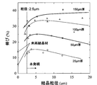
- the reason why the particle size ⁇ 2.5 ⁇ m is satisfied is that, as shown in FIG. 1, when the particle size is less than 2.5 ⁇ m, the elongation greatly decreases and the workability decreases. .
- FIG. 1 is a diagram illustrating the relationship between crystal grain size and elongation in a tensile test of a titanium thin plate. As shown in the figure, when the crystal grain size is less than 2.5 ⁇ m, the strength is excessively increased even if there is no non-recrystallized grain, and the elongation is greatly reduced.
- plate thickness (mm) / particle size (mm) ⁇ 3 (hereinafter, “plate thickness (mm) / particle size (mm)” is also simply referred to as “plate thickness / particle size”) is satisfied. The reason is as follows.
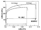
- FIG. 2 is a diagram illustrating the relationship between stress and strain in a tensile test of a titanium thin plate (foil) having a thickness of 25 ⁇ m.
- particle size: 5.3 ⁇ m and “particle size: 12.3 ⁇ m” are measurement results for test pieces having average particle sizes of 5.3 ⁇ m and 12.3 ⁇ m, respectively.
- FIG. 2 in any of the test pieces, after a uniform elongation state has elapsed, local deformation is started, and breakage occurs. The local deformation amount is small, and the uniform deformation amount, that is, uniform elongation is an index of workability, and a decrease in this indicates a decrease in workability.
- FIG. 2 shows this state.
- the upper limit of the average crystal grain size range in which workability can be improved by coarsening is determined by the number of crystal grains existing in the plate thickness direction, that is, the ratio of plate thickness / grain size.
- the titanium thin plate of the present invention it is necessary to have a hardened layer in a region having a depth of 200 nm to 2 ⁇ m from the surface. In other words, it is necessary to have a cured layer having a thickness of 200 nm to 2 ⁇ m in the vicinity of the surface.
- the hardened layer is a concentrated layer of carbon, nitrogen, oxygen derived from the rolling oil remaining on the surface at the time of annealing, oxygen, nitrogen, and oxygen formed by nitrogen and oxygen gas contained in the gas atmosphere of the annealing furnace, A region containing 0.5 mass% or more of oxygen, a region containing 0.5 mass% or more of nitrogen, a region containing 0.5 mass% or more of carbon, or a total of 0.5 mass% or more of oxygen, nitrogen and carbon It is an area.
- the thickness of the hardened layer can be measured by GDS (Glow Discharge Optical Emission Analyzer).
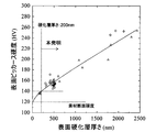
- FIG. 4 is a diagram showing the relationship between the thickness of the hardened layer and the surface hardness of the titanium thin plate.
- the surface hardness increases as the hardened layer thickness increases.
- the thickness of the hardened layer is less than 200 nm, it is almost the same as the material hardness measured in the cross section of the material (shown in FIG. 4), and no increase in hardness is observed.
- the thickness of the cured layer is 200 nm or more.
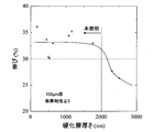
- FIG. 5 is a diagram illustrating the relationship between the hardened layer thickness and elongation for a titanium thin plate having a thickness of 100 ⁇ m and a plate thickness / particle size ⁇ 3. As shown in FIG. 5, even if the plate thickness / particle size ⁇ 3, the cured layer thickness is 2000 nm (2 ⁇ m), because if the cured layer thickness is too thick, the elongation decreases and the workability decreases. The following.
- the titanium thin plate of the present invention is subjected to finish annealing at 500 ° C. or more and 850 ° C. or less by BAF or continuous annealing after cold rolling, it is desirable because stable workability is ensured.
- the recrystallization temperature of the titanium thin plate of the present invention is 500 ° C.
- finish annealing is performed at 500 ° C. or higher.
- the temperature is set to 850 ° C. or less. Even in a normal operation, an operation in accordance with the purpose of the annealing treatment is performed. However, by performing the final annealing under the desirable temperature condition, workability is stably ensured.
- the thickness of the hardened layer can be obtained by changing the residual amount of rolling oil in a cleaning process usually performed after cold rolling, or by changing the residual nitrogen and oxygen amount in a bright annealing furnace. It is possible.
- a cold rolled sheet having a thickness of 25 ⁇ m to 150 ⁇ m was manufactured through cold rolling and intermediate annealing for one type of pure titanium (thickness 0.5 mm) specified in JISH4600. Subsequently, the crystal grain size was changed variously by performing finish annealing in an Ar atmosphere (dew point ⁇ ⁇ 40 ° C.) under different conditions.
- a hardened layer was formed by concentrating oxygen, nitrogen, or carbon on the surface of the plate with the rolling oil remaining on the surface of the plate or the gas atmosphere of the annealing furnace. The thickness (depth) of the hardened layer was adjusted by changing the remaining amount of rolling oil and the amount of nitrogen and oxygen in the atmosphere during bright annealing.
- each test piece after finish annealing was processed into a test piece having a parallel part width of 6.25 mm and a parallel part length of 50 mm, and then a tensile test was performed. Moreover, about each test piece, plate
- the tensile test is performed at room temperature in a direction parallel to the rolling direction (L direction) with a strain rate of 0.5% / min up to 0.2% proof stress and then 20% / min up to fracture. It was.
- the crystal grain size was obtained by square approximation using a quadrature method for an area of 40,000 ⁇ m 2 or more on the sample surface.
- the surface hardness was evaluated by using a Vickers hardness tester, pushing a Vickers indenter into the sample surface with a load of 0.245 N (25 gf), and an average value of 10 points.
- the thickness of the hardened layer was determined by analyzing the depth direction of oxygen, nitrogen, carbon, titanium, and iron by Ar ion sputtering in an area of 4 mm in diameter on the sample surface using GDS. Or a total thickness of these layers was 0.5 mass% or more. For quantification, each measured value was measured using zinc oxide (oxygen 19.8 mass%) for oxygen, austenitic stainless steel (containing 0.3 mass% nitrogen) for nitrogen, and titanium alloy (carbon And 0.12 mass%) were calibrated, and the depth direction analysis of each element was performed by making it correspond to the measurement site
- Comparative Example 1 and Comparative Example 4 were both cases where unrecrystallized grains remained, and the elongation was extremely low.
- Comparative Examples 2, 3, 5, 6, 11, 12, 16, and 17, all were (plate thickness / particle size) ⁇ 3, and the elongation was remarkably low.
- Comparative Example 17 had a lower elongation than Invention Examples 18-23.
- Comparative Example 7 and Comparative Example 13 when the crystal grain size was too fine (less than 2.5 ⁇ m), the elongation was low.
- the thickness of the cured layer was larger than the thickness specified in the present invention (200 nm or more and 2 ⁇ m or less), and the elongation was low.
- Comparative Example 12 had a plate thickness / particle diameter of less than 3 and a hardened layer, so that the elongation was lower than those of Invention Examples 11 to 17.
- the thickness / particle diameter was less than 3 and the cured layer was thick, so that the elongation was lower than those of Inventive Examples 18-23.
- the thickness of the cured layer was thin (less than 200 nm), the 0.2% proof stress was low, and the shape retention was not good.
- the proof stress of the comparative example 14 was remarkably low as compared with the inventive example 22 having substantially the same particle size.
- Comparative Example 15 the proof stress was remarkably low as compared with Inventive Example 23 having substantially the same particle size.
- Comparative Example 1 has a low elongation due to the non-recrystallized structure.
- the plate thickness / particle diameter is less than 3, and the elongation, proof stress, and tensile strength are low as compared with Examples 1 to 5 of the present invention.
- “About 50 ⁇ m materials” Comparative Example 4 has a low elongation due to the non-recrystallized structure.
- the plate thickness / particle size is less than 3, and the elongation, proof stress, and tensile strength are low as compared with Examples 6 to 10 of the present invention.
- Comparative Example 7 is too fine and has low elongation.
- Comparative Example 8 the thickness / particle size ⁇ 3 is satisfied, but the cured layer is thick and the elongation is low.
- Comparative Example 9 the yield strength is significantly lower than that of Inventive Example 17 in which the cured layer is thin and the particle size is substantially the same.
- Comparative Example 10 the cured layer is thick and the elongation is lower than those of Invention Examples 11 to 17.
- the plate thickness / particle diameter is less than 3, and the elongation is lower than those of Invention Examples 11-17.
- Comparative Example 12 the plate thickness / particle diameter is less than 3, and the cured layer is thick, so that the elongation is lower than those of Invention Examples 11-17. “About 150 ⁇ m materials” Comparative Example 13 is too fine and has low elongation.
- Comparative Example 14 the yield strength is significantly lower than that of Inventive Example 22 in which the cured layer is thin and the particle diameter is substantially the same.
- Comparative Example 15 the yield strength is significantly lower than that of Invention Example 23 in which the cured layer is thin and the particle diameter is substantially the same.
- Comparative Example 16 the plate thickness / particle diameter is less than 3, and the cured layer is thick, so the elongation is lower than those of Invention Examples 18-23.
- Comparative Example 17 the plate thickness / particle size is less than 3, and the elongation is lower than those of Invention Examples 18-23.
- Examples 1 to 23 of the present invention all satisfy the conditions specified in the present invention and exhibited high elongation and surface hardness.
- the titanium thin plate of the present invention has excellent workability and high surface hardness, and can be used for a wide range of applications as consumer products and industrial materials such as speaker diaphragms.
Landscapes
- Chemical & Material Sciences (AREA)
- Engineering & Computer Science (AREA)
- Materials Engineering (AREA)
- Mechanical Engineering (AREA)
- Metallurgy (AREA)
- Organic Chemistry (AREA)
- Physics & Mathematics (AREA)
- Thermal Sciences (AREA)
- Crystallography & Structural Chemistry (AREA)
- Heat Treatment Of Sheet Steel (AREA)
Abstract
Description
すなわち、板厚が0.2mm以下のチタン薄板であって、バルクのFeが0.1mass%以下、O(酸素)が0.1mass%以下であり、板厚(mm)/粒径(mm)≧3で、かつ粒径≧2.5μmを満たし、表面に硬化層を有し、前記硬化層の領域が、表面から深さ200nm以上2μm以下である、チタン薄板である。
ここでいう「チタン薄板」とは、JISH4600に規定される工業用純チタンで、板厚が0.2mm以下の薄板ないしは箔を指す。
前記の「粒径」とは、JISH0501に規定されている求積法により求められる平均粒径を意味する。それを強調して「平均粒径」と記すこともある。
また、「硬化層」とは、焼鈍時に、表面に残存する圧延油に由来する炭素や窒素、酸素、焼鈍炉のガス雰囲気に含まれる窒素および酸素ガスによって形成される酸素、窒素、炭素の濃化層を指す。
図2に示したように、いずれの試験片においても、均一伸びの状態を経過した後、局所変形を開始し、破断に至る。局部変形量は小さく、均一変形量すなわち、均一伸びが加工性の指標であり、これが低下することは加工性の低下を示す。
まず、JISH4600に規定される1種の純チタン(厚さ0.5mm)について、冷間圧延および中間焼鈍を経て、25μm~150μm厚の冷延板を製造した。続いて、Ar雰囲気(露点≦-40℃)中で条件を変えて仕上げ焼鈍を行うことにより結晶粒径を種々変化させた。また、板の表面に残存させた圧延油や、焼鈍炉のガス雰囲気により、板の表面に酸素、窒素、炭素のいずれかを濃化させて硬化層を形成した。硬化層の厚さ(深さ)は、圧延油の残存量や光輝焼鈍時の雰囲気中の窒素量及び酸素量を変化させて、調整した。

比較例2、3、5、6、11、12、16、17は、いずれも(板厚/粒径)<3の場合であり、伸びが著しく低かった。特に、比較例17は、本発明例18~23よりも伸びが低かった。
比較例7および比較例13は、いずれも結晶粒径が微細すぎる場合(2.5μm未満)で、伸びが低かった。
比較例8、10、12は、硬化層の厚さが本発明で規定する厚さ(200nm以上2μm以下)よりも大きい場合で、伸びが低かった。特に、比較例12は、板厚/粒径が3未満であり、硬化層も厚いため、本発明例11~17よりも伸びが低くかった。比較例16は、板厚/粒径が3未満であり、硬化層も厚いため、本発明例18~23よりも伸びが低かった。
比較例9、14、15は、硬化層の厚さが薄く(200nm未満)、0.2%耐力が低く、形状保持性が良くなかった。特に、比較例14は、粒径がほぼ同じ本発明例22と比較して、耐力が著しく低かった。比較例15は、粒径がほぼ同じ本発明例23と比較して、耐力が著しく低かった。
「25μm材について」
比較例1は、未再結晶組織のため、伸びが低い。
比較例2、3は、板厚/粒径が3未満であり、本発明例1~5と比較して、伸び、耐力、引張強度が低い。
「50μm材について」
比較例4は、未再結晶組織のため、伸びが低い。
比較例5、6は、板厚/粒径が3未満であり、本発明例6~10と比較して、伸び、耐力、引張強度が低い。
「100μm材について」
比較例7は、細粒化しすぎて、伸びが低い。
比較例8は、板厚/粒径≧3を満たしているが、硬化層が厚く、伸びが低い。
比較例9は、硬化層が薄く、粒径がほぼ同じ本発明例17と比較して、耐力が著しく低い。
比較例10は、硬化層が厚く、本発明例11~17よりも伸びが低い。
比較例11は、板厚/粒径が3未満であり、本発明例11~17よりも伸びが低い。
比較例12は、板厚/粒径が3未満であり、硬化層も厚いため、本発明例11~17よりも伸びが低い。
「150μm材について」
比較例13は、細粒化しすぎて、伸びが低い。
比較例14は、硬化層が薄く、粒径がほぼ同じ本発明例22と比較して、耐力が著しく低い。
比較例15は、硬化層が薄く、粒径がほぼ同じ本発明例23と比較して、耐力が著しく低い。
比較例16は、板厚/粒径が3未満であり、硬化層も厚いため、本発明例18~23よりも伸びが低い。
比較例17は、板厚/粒径が3未満であり、本発明例18~23よりも伸びが低い。
Claims (2)
- 板厚が0.2mm以下のチタン薄板であって、
バルクのFeが0.1mass%以下、O(酸素)が0.1mass%以下であり、
板厚(mm)/粒径(mm)≧3で、かつ粒径≧2.5μmを満たし、
表面に硬化層を有し、前記硬化層の領域が、表面から深さ200nm以上2μm以下である、チタン薄板。 - 冷間圧延後、BAFもしくは連続焼鈍によって500℃以上850℃以下で仕上げ焼鈍が施されている、請求項1に記載のチタン薄板。
Priority Applications (3)
| Application Number | Priority Date | Filing Date | Title |
|---|---|---|---|
| CN201380042066.0A CN104520455B (zh) | 2012-08-14 | 2013-08-13 | 钛薄板 |
| US14/403,437 US20150152538A1 (en) | 2012-08-14 | 2013-08-13 | Titanium thin sheet |
| JP2014530559A JP5776850B2 (ja) | 2012-08-14 | 2013-08-13 | チタン薄板 |
Applications Claiming Priority (2)
| Application Number | Priority Date | Filing Date | Title |
|---|---|---|---|
| JP2012179861 | 2012-08-14 | ||
| JP2012-179861 | 2012-08-14 |
Publications (1)
| Publication Number | Publication Date |
|---|---|
| WO2014027657A1 true WO2014027657A1 (ja) | 2014-02-20 |
Family
ID=50685605
Family Applications (1)
| Application Number | Title | Priority Date | Filing Date |
|---|---|---|---|
| PCT/JP2013/071869 Ceased WO2014027657A1 (ja) | 2012-08-14 | 2013-08-13 | チタン薄板 |
Country Status (5)
| Country | Link |
|---|---|
| US (1) | US20150152538A1 (ja) |
| JP (1) | JP5776850B2 (ja) |
| CN (1) | CN104520455B (ja) |
| TW (1) | TWI493048B (ja) |
| WO (1) | WO2014027657A1 (ja) |
Cited By (4)
| Publication number | Priority date | Publication date | Assignee | Title |
|---|---|---|---|---|
| JP2016156054A (ja) * | 2015-02-24 | 2016-09-01 | 新日鐵住金株式会社 | チタン板とその製造方法 |
| JP2017031460A (ja) * | 2015-07-31 | 2017-02-09 | 新日鐵住金株式会社 | チタン板 |
| JP6156597B1 (ja) * | 2016-06-30 | 2017-07-05 | 新日鐵住金株式会社 | チタン薄板及びその製造方法 |
| JP2023125429A (ja) * | 2022-02-28 | 2023-09-07 | 東邦チタニウム株式会社 | チタン箔の製造方法及びチタン箔 |
Families Citing this family (3)
| Publication number | Priority date | Publication date | Assignee | Title |
|---|---|---|---|---|
| JP5482962B2 (ja) | 2011-03-01 | 2014-05-07 | 新日鐵住金株式会社 | レーザー加工用金属板とレーザー加工用ステンレス鋼板の製造方法 |
| CN113260727B (zh) * | 2019-04-17 | 2022-06-28 | 日本制铁株式会社 | 钛板和铜箔制造滚筒 |
| KR102608727B1 (ko) * | 2019-04-17 | 2023-12-04 | 닛폰세이테츠 가부시키가이샤 | 티타늄판, 티타늄 압연 코일 및 구리박 제조 드럼 |
Citations (3)
| Publication number | Priority date | Publication date | Assignee | Title |
|---|---|---|---|---|
| JP2002180236A (ja) * | 2000-12-15 | 2002-06-26 | Nippon Steel Corp | チタン薄板とその製造方法 |
| JP2009097060A (ja) * | 2007-10-19 | 2009-05-07 | Sumitomo Metal Ind Ltd | チタン材ならびにチタン材製造方法 |
| JP2010202952A (ja) * | 2009-03-05 | 2010-09-16 | Nippon Steel Corp | プレス成形性に優れたチタン合金薄板およびその製造方法 |
Family Cites Families (4)
| Publication number | Priority date | Publication date | Assignee | Title |
|---|---|---|---|---|
| JP3352885B2 (ja) * | 1996-08-21 | 2002-12-03 | 新日本製鐵株式会社 | チタン薄板およびその製造方法 |
| CN101050495A (zh) * | 2007-05-16 | 2007-10-10 | 宝鸡市嘉诚稀有金属材料有限公司 | 高塑性钛薄板的制造方法 |
| CN102245794A (zh) * | 2008-12-17 | 2011-11-16 | 住友金属工业株式会社 | 钛材以及钛材制造方法 |
| JP5700650B2 (ja) * | 2011-01-28 | 2015-04-15 | 株式会社神戸製鋼所 | プレス成形性と強度のバランスに優れた純チタン板 |
-
2013
- 2013-08-13 JP JP2014530559A patent/JP5776850B2/ja active Active
- 2013-08-13 US US14/403,437 patent/US20150152538A1/en not_active Abandoned
- 2013-08-13 WO PCT/JP2013/071869 patent/WO2014027657A1/ja not_active Ceased
- 2013-08-13 CN CN201380042066.0A patent/CN104520455B/zh active Active
- 2013-08-14 TW TW102129119A patent/TWI493048B/zh active
Patent Citations (3)
| Publication number | Priority date | Publication date | Assignee | Title |
|---|---|---|---|---|
| JP2002180236A (ja) * | 2000-12-15 | 2002-06-26 | Nippon Steel Corp | チタン薄板とその製造方法 |
| JP2009097060A (ja) * | 2007-10-19 | 2009-05-07 | Sumitomo Metal Ind Ltd | チタン材ならびにチタン材製造方法 |
| JP2010202952A (ja) * | 2009-03-05 | 2010-09-16 | Nippon Steel Corp | プレス成形性に優れたチタン合金薄板およびその製造方法 |
Cited By (5)
| Publication number | Priority date | Publication date | Assignee | Title |
|---|---|---|---|---|
| JP2016156054A (ja) * | 2015-02-24 | 2016-09-01 | 新日鐵住金株式会社 | チタン板とその製造方法 |
| JP2017031460A (ja) * | 2015-07-31 | 2017-02-09 | 新日鐵住金株式会社 | チタン板 |
| JP6156597B1 (ja) * | 2016-06-30 | 2017-07-05 | 新日鐵住金株式会社 | チタン薄板及びその製造方法 |
| WO2018003098A1 (ja) * | 2016-06-30 | 2018-01-04 | 新日鐵住金株式会社 | チタン薄板及びその製造方法 |
| JP2023125429A (ja) * | 2022-02-28 | 2023-09-07 | 東邦チタニウム株式会社 | チタン箔の製造方法及びチタン箔 |
Also Published As
| Publication number | Publication date |
|---|---|
| TW201414856A (zh) | 2014-04-16 |
| JP5776850B2 (ja) | 2015-09-09 |
| JPWO2014027657A1 (ja) | 2016-07-28 |
| CN104520455B (zh) | 2017-02-22 |
| US20150152538A1 (en) | 2015-06-04 |
| CN104520455A (zh) | 2015-04-15 |
| TWI493048B (zh) | 2015-07-21 |
Similar Documents
| Publication | Publication Date | Title |
|---|---|---|
| JP5776850B2 (ja) | チタン薄板 | |
| CN101999009B (zh) | 高强度容器用钢板及其制造方法 | |
| JP5453884B2 (ja) | 高強度容器用鋼板およびその製造方法 | |
| JP6156597B1 (ja) | チタン薄板及びその製造方法 | |
| CN114807776A (zh) | 钢、由所述钢制成的产品及其制造方法 | |
| CN102317485B (zh) | 钛板 | |
| TW201629242A (zh) | 沖壓罐用鋼板及其製造方法 | |
| WO2010101074A1 (ja) | 曲げ加工性に優れた冷延鋼板、その製造方法およびそれを用いた部材 | |
| WO2016060248A1 (ja) | 絞り缶用鋼板及びその製造方法 | |
| TWI428453B (zh) | 罐用鋼板及其製造方法 | |
| JPWO2019043882A1 (ja) | チタン板 | |
| US5362441A (en) | Ti-Al-V-Mo-O alloys with an iron group element | |
| JP2017190469A (ja) | 絞り缶用冷延鋼板及びその製造方法 | |
| JP6610062B2 (ja) | チタン板 | |
| EP2634282A1 (en) | Steel sheet for can, and process for producing same | |
| JP5032011B2 (ja) | 硬質α黄銅及びその硬質α黄銅の製造方法 | |
| JP3222239B2 (ja) | 高いbh性を有する加工性に優れた硬質表面処理原板 | |
| JP5515948B2 (ja) | 板厚方向の材質均一性に優れた極低炭素鋼材の製造方法 | |
| JPWO2018194059A1 (ja) | 鋼板及びその製造方法 | |
| JP4452753B1 (ja) | プレス成形性と強度のバランスに優れたチタンまたはチタン合金板 | |
| JP2016191123A (ja) | チタン極薄板及びその製造方法 | |
| CN120888736A (zh) | 一种提高深冲冷轧板深冲性能的生产方法 | |
| JP4783214B2 (ja) | プレス加工性に優れたチタン合金およびプレス成形部材 | |
| WO2005083140A1 (ja) | 高強度極薄冷延鋼板、その製造方法、それを用いたガスケット用材料およびそれを用いたガスケット材 | |
| JP2007146235A (ja) | 液晶フロントフレーム用表面処理鋼板、その製造方法およびその製造方法により製造された液晶フロントフレーム |
Legal Events
| Date | Code | Title | Description |
|---|---|---|---|
| ENP | Entry into the national phase |
Ref document number: 2014530559 Country of ref document: JP Kind code of ref document: A |
|
| 121 | Ep: the epo has been informed by wipo that ep was designated in this application |
Ref document number: 13879627 Country of ref document: EP Kind code of ref document: A1 |
|
| WWE | Wipo information: entry into national phase |
Ref document number: 14403437 Country of ref document: US |
|
| NENP | Non-entry into the national phase |
Ref country code: DE |
|
| 122 | Ep: pct application non-entry in european phase |
Ref document number: 13879627 Country of ref document: EP Kind code of ref document: A1 |