WO2014024660A1 - Appareil de production de gaz fluor et son procédé de commande - Google Patents
Appareil de production de gaz fluor et son procédé de commande Download PDFInfo
- Publication number
- WO2014024660A1 WO2014024660A1 PCT/JP2013/069596 JP2013069596W WO2014024660A1 WO 2014024660 A1 WO2014024660 A1 WO 2014024660A1 JP 2013069596 W JP2013069596 W JP 2013069596W WO 2014024660 A1 WO2014024660 A1 WO 2014024660A1
- Authority
- WO
- WIPO (PCT)
- Prior art keywords
- fluorine gas
- electrolytic
- gas
- fluorine
- electrolytic cell
- Prior art date
Links
Images

Classifications
-
- C—CHEMISTRY; METALLURGY
- C01—INORGANIC CHEMISTRY
- C01B—NON-METALLIC ELEMENTS; COMPOUNDS THEREOF; METALLOIDS OR COMPOUNDS THEREOF NOT COVERED BY SUBCLASS C01C
- C01B7/00—Halogens; Halogen acids
- C01B7/19—Fluorine; Hydrogen fluoride
- C01B7/20—Fluorine
-
- C—CHEMISTRY; METALLURGY
- C25—ELECTROLYTIC OR ELECTROPHORETIC PROCESSES; APPARATUS THEREFOR
- C25B—ELECTROLYTIC OR ELECTROPHORETIC PROCESSES FOR THE PRODUCTION OF COMPOUNDS OR NON-METALS; APPARATUS THEREFOR
- C25B1/00—Electrolytic production of inorganic compounds or non-metals
- C25B1/01—Products
- C25B1/24—Halogens or compounds thereof
- C25B1/245—Fluorine; Compounds thereof
-
- C—CHEMISTRY; METALLURGY
- C25—ELECTROLYTIC OR ELECTROPHORETIC PROCESSES; APPARATUS THEREFOR
- C25B—ELECTROLYTIC OR ELECTROPHORETIC PROCESSES FOR THE PRODUCTION OF COMPOUNDS OR NON-METALS; APPARATUS THEREFOR
- C25B15/00—Operating or servicing cells
- C25B15/02—Process control or regulation
Definitions
- the present invention relates to a fluorine gas generation device and a control method for the fluorine gas generation device.
- Patent Document 1 includes an electrolytic bath for electrolyzing hydrogen fluoride in an electrolytic bath made of a molten salt containing hydrogen fluoride, and generates a product gas containing fluorine gas as a main component in the first gas phase portion on the anode side.
- a fluorine gas generation device that generates a by-product gas mainly containing hydrogen gas in a second gas phase portion on the cathode side is disclosed.
- the product gas is stored in the main buffer tank, and the pressure in the main buffer tank is measured with a pressure gauge.
- the measurement result of the pressure gauge is transmitted to the control unit, and the control unit performs on / off control of the current source based on the measurement result of the pressure gauge.
- the amount of product gas generated at the anode is controlled based on the pressure in the main buffer tank.
- Patent Document 2 discloses a method for controlling current to an electrolytic cell necessary for electrolysis.
- the current control method described in Patent Document 2 measures the voltage fluctuation width between the cathode and the anode when a constant current is applied to the electrolytic cell, and changes the input current amount according to the voltage fluctuation width. It is a method of applying.
- the power supply method to the electrolytic cell necessary for the electrolysis of the fluorine gas generator is generally the current value output from the power supply device as described in Patent Document 1 and Patent Document 2. And the power is controlled so that the voltage value fluctuates according to the course. This is because the relationship of the following (Equation 1) is established between the flow rate of fluorine gas generated from the electrolytic cell by electrolysis and the current value energized in the electrolytic cell, and by controlling the current value, This is because the flow rate of fluorine gas generated from the electrolytic cell can be controlled.
- the voltage applied in energizing the electrolytic cell is a theoretical electrolysis voltage (about 2.9 V) calculated from the standard electrode potential of fluorine and hydrogen generated by electrolysis.
- it is a value obtained by adding the voltage generated due to the activation overvoltage and the electrical resistance of the members constituting the electrolytic cell.
- the activation overvoltage is a voltage resulting from energy required for activation of the electrolytic reaction, and varies depending on the type of electrode and the composition of the electrolytic bath.
- the resistance is the total of the resistance of the member that is energized among the members included in the electrolytic cell, the contact resistance of each member, and the wiring that connects the electrolytic cell and the power supply device. Since these resistance values are determined by the configuration of the electrolytic cell and the material used, the same value can be obtained if the electrolytic cell has the same structure.
- anode effect occurs in which no current flows even when a voltage is applied.
- the fluorine gas generated by electrolysis is very corrosive, so the members inside the electrolytic cell may be corroded.
- the electrolytic bath is a molten salt containing hydrogen fluoride
- the members inside the electrolytic cell may be corroded by hydrogen fluoride. Since the electrical resistance increases due to the progress of the corrosion, the voltage applied to allow the same current to flow increases. When the voltage increases, the load (current ⁇ voltage) applied to the electrolytic cell (electrode pair) increases, so that electric corrosion tends to occur, and Joule heat (current ⁇ voltage ⁇ time) increases.
- an increase in Joule heat leads to an increase in temperature in the electrolytic cell, further increasing the reactivity between the surface of the anode and fluorine gas, thereby further promoting the corrosion of the anode.
- fluorine gas is generated using a plurality of electrolytic cells, the progress of corrosion or the frequency of occurrence of the anode effect differs depending on the electrolytic cell.
- corrosion of the member is further promoted, and problems such as an increase in maintenance frequency of the electrolytic cell occur.
- the present invention has been made in view of the above problems, and in a fluorine gas generation apparatus that generates fluorine gas using a plurality of electrolytic cells, the use of the electrolytic cell generated by the difference in electrode resistance between the electrolytic cells.
- An object of the present invention is to provide a fluorine gas generation device capable of automatically supplying fluorine gas stably while reducing shortening of life.
- One aspect of the present invention is a fluorine gas generation device that generates fluorine gas by electrolyzing a fluorine compound in an electrolytic bath, each of which includes a container and a fluorine compound contained in the container.
- An electrolytic cell a power source for supplying electric power necessary for generating fluorine gas by electrolysis to the plurality of electrolytic cells, and an actual current detection for detecting a current supplied from the power source to the plurality of electrolytic cells And a total sum of currents applied to the plurality of electrolytic cells based on the amount of gas containing fluorine gas generated by the plurality of electrolytic cells, and the plurality of currents detected by the actual current detector.
- the power supply is set at the output voltage so that the value of the voltage applied to the plurality of electrolytic cells increases or decreases in the same direction.
- a controller for controlling.
- Fluorine gas when controlling the power to a plurality of electrolytic cells in the fluorine gas generator, while reducing the shortening of the service life of the electrolytic cell caused by the difference in electrical resistance between the electrolytic cells, Fluorine gas can be supplied automatically and stably.
- the fluorine gas generation device of this embodiment generates fluorine gas using a plurality of electrolytic cells. Each electrolytic cell generates fluorine gas by electrolysis in an electrolytic bath containing a fluorine compound.
- the fluorine gas generation device of the present embodiment determines the total current value to be supplied to the plurality of electrolytic cells in the control of the amount of fluorine gas generated in the plurality of electrolytic cells, and according to the determined total current value, The voltage supplied to each electrolytic cell is adjusted.
- the fluorine gas generation device of the present embodiment is a fluorine gas generation device including a plurality of electrolytic cells that generate fluorine gas, without significantly increasing only the load applied to some of the electrolytic cells in the plurality of electrolytic cells. Gas is supplied automatically and stably.
- the fluorine gas generation device of the present embodiment has a plurality of electrolytic cells (electrolytic cell units).
- electrolytic cell units electrolytic cell units
- the electrolytic cell unit 50 of the present embodiment includes an electrolytic cell 1 that generates fluorine gas by electrolysis, devices and valves for controlling the electrolytic cell 1, and a path for deriving the gas generated in the electrolytic cell 1 ( Including valve).
- the electrolytic cell unit 50 is controlled by the controller 10.
- the controller 10 controls the operation of each device and each valve based on the detection result (monitoring result) output from each meter.
- the controller 10 controls each electrolytic cell unit 50 and other devices and valves.
- FIG. 1 illustrates a plurality of rectangles indicated by reference numeral “10” for convenience of explanation, and these all indicate the same controller 10.
- the controller 10 can include separate components (control devices) assigned to each electrolytic cell 1 unit.
- the controller 10 can include different components (control devices) that control different equipment and valves.
- the controller 10 includes, for example, a CPU that is a processor, a ROM that is a nonvolatile storage device that stores a program and control data used by the program, and a microcomputer that includes a RAM that is a main storage device. Programs and data stored in the ROM are loaded into the RAM.
- the CPU realizes a predetermined function implemented in the controller 10 by executing a program stored in the RAM.
- the RAM stores a program executed by the processor and control data necessary for executing the program.
- the hardware configuration of the controller 10 is not limited. For example, part or all of the functions of the controller 10 may be realized by a logic circuit.
- the molten salt containing hydrogen fluoride (HF) is stored in the container of the electrolytic cell 1.
- a mixture (KF ⁇ 2HF) of hydrogen fluoride and potassium fluoride (KF) is used as the molten salt.
- KF ⁇ 2HF hydrogen fluoride
- KF potassium fluoride
- the inside of the electrolytic cell 1 is partitioned into an anode chamber 11 and a cathode chamber 12 by a partition wall 6 that is partially immersed in the molten salt and partially exposed on the molten salt.
- Each of the anode chamber 11 and the cathode chamber 12 includes a portion filled in the molten salt and an air chamber on the surface of the molten salt liquid.
- the electrolytic cell 1 has an anode 7 and a cathode 8, and the anode 7 and the cathode 8 are immersed in the molten salts of the anode chamber 11 and the cathode chamber 12, respectively.
- a main raw gas mainly composed of fluorine gas (F 2 ) is generated at the anode 7.
- By-product gas mainly containing hydrogen gas (H 2 ) is generated.
- a carbon electrode for example, a carbon electrode is used, and for the cathode 8, for example, soft iron, monel, or nickel is used.
- the materials of the anode 7 and the cathode 8 are not limited to these, and appropriate materials are selected depending on the design.
- the air chamber 121 is partitioned by the partition wall 6 so that the mutual gas cannot come and go.
- the first air chamber 111 and the second air chamber 121 are completely separated by the partition wall 6 in order to prevent a reaction due to the contact of fluorine gas and hydrogen gas.
- the molten salt in the anode chamber 11 and the cathode chamber 12 is not separated by the partition wall 6, and the anode chamber 11 and the cathode chamber 12 communicate with each other in the molten salt through the lower portion of the partition wall 6.
- the main gas outlet passage 60 for leading the main gas generated at the anode 7 is connected to the first air chamber 111.
- the second gas chamber 121 is connected to a by-product gas outlet path 70 for extracting the by-product gas generated at the cathode 8.
- each of the fluorine gas and the hydrogen gas generated from the anode 7 and the cathode 8 of the electrolytic cell 1 hydrogen fluoride is vaporized from the molten salt by the vapor pressure and mixed.
- each of the main product gas generated at the anode 7 and guided to the first air chamber 111 and the by-product gas generated at the cathode 8 and guided to the second air chamber 121 contains hydrogen fluoride gas. It is.
- the electrolytic cell unit 50 includes a temperature adjusting device 65 that adjusts the temperature of the molten salt in the electrolytic cell 1.
- the temperature of the molten salt in the electrolytic cell 1 is adjusted by the temperature adjusting device 65 to 71.7 ° C. or higher, for example, 85 to 95 ° C., which is the melting point of KF ⁇ 2HF.
- the electrolytic cell unit 50 is installed in the electrolytic cell 1 and includes a thermometer 69 as a temperature detector that detects the temperature of the molten salt. The detection result of the thermometer 69 is output to the controller 10.
- the temperature adjusting device 65 includes a jacket 66 set on the outer wall of the electrolytic cell 1, a tube (not shown) set inside the electrolytic cell 1, and is installed outside the electrolytic cell 1.
- a heating / cooling device 67 for circulating steam or cooling water through the tube is provided.
- the controller 10 controls the temperature adjustment device 65 according to the temperature detected by the thermometer 69.
- the temperature adjustment device 65 adjusts the temperature of the molten salt. Specifically, the temperature adjusting device 65 circulates steam from the heating / cooling device 67 to the jacket 66 and the tube when raising the temperature of the molten salt, and lowers the temperature of the molten salt when heating the cooling salt 67. Then, cooling water is circulated through the jacket 66 and the tube.
- the configuration and presence of the temperature control device 65 of the electrolytic cell 1 depend on the design. For example, only one of the jacket 66 and the tube may be installed. Further, instead of circulating steam or cooling water through the jacket 66 and the tube, a hot refrigerant such as silicone oil may be circulated. Furthermore, you may make it adjust the temperature of molten salt by providing heat exchangers, such as a heater and a capacitor
- heat exchangers such as a heater and a capacitor
- the electrolytic cell 1 is provided with a liquid level gauge 14 as a liquid level detector for detecting the liquid level of the stored molten salt.
- the liquid level gauge 14 detects the back pressure when the nitrogen gas at a constant flow rate is purged into the molten salt through the insertion tube 141 inserted in the electrolytic cell 1, and the liquid level gauge 14 detects the liquid pressure from the back pressure and the liquid specific gravity of the molten salt. It is a back pressure type liquid level gauge that detects the surface level.
- the detection result of the liquid level gauge 14 is output to the controller 10.
- the electrolytic cell unit 50 includes a differential pressure gauge 20 as a differential pressure detector that detects a pressure difference between the first air chamber 111 and the second air chamber 121 of the electrolytic cell 1. The detection result of the differential pressure gauge 20 is output to the controller 10.
- the electrolytic cell unit 50 includes a raw material supply system 5 that supplies hydrogen fluoride, which is a raw material of fluorine gas, into the molten salt of the electrolytic cell 1.
- a raw material supply system 5 that supplies hydrogen fluoride, which is a raw material of fluorine gas, into the molten salt of the electrolytic cell 1.
- the raw material supply system 5 is demonstrated.
- the raw material supply system 5 is installed outside the electrolytic cell 1 with the raw material supply passage 41 connected to the electrolytic cell 1, connected to the electrolytic cell 1 through the raw material supply channel 41, and supplemented to the electrolytic cell 1.
- a hydrogen fluoride supply source 40 in which hydrogen fluoride is stored. Hydrogen fluoride stored in the hydrogen fluoride supply source 40 is supplied into the molten salt of the electrolytic cell 1 through the raw material supply passage 41.
- the raw material supply passage 41 is provided with a flow rate control valve 42 for controlling the supply flow rate of hydrogen fluoride.
- the controller 10 controls the flow control valve 42 (the opening thereof), and the flow control valve 42 adjusts the opening based on a signal output from the controller 10. Specifically, the controller 10 controls the supply flow rate of hydrogen fluoride so that the liquid level of the molten salt detected by the level gauge 14 is stored in the ROM and becomes a predetermined level set in advance. That is, the flow rate control valve 42 controls the supply flow rate of hydrogen fluoride so as to replenish hydrogen fluoride electrolyzed in the molten salt.
- a carrier gas supply passage 46 that guides a carrier gas supplied from a carrier gas supply source 45 installed outside the electrolytic cell unit 50 into the raw material supply passage 41 is connected to the raw material supply passage 41.
- the carrier gas supply passage 46 is provided with a cutoff valve 47 for switching between supply and cutoff of the carrier gas.
- the carrier gas is a gas for introducing hydrogen fluoride into the molten salt, and for example, nitrogen gas that is an inert gas is used.
- nitrogen gas is supplied into the molten salt in the cathode chamber 12.
- the nitrogen gas is hardly dissolved in the molten salt and is discharged from the second air chamber 121 through the byproduct gas processing system.
- another inert gas such as argon gas or helium gas may be used as the carrier gas.
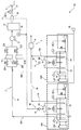
- the fluorine gas generation device 100 includes a plurality of electrolytic cell units, and supplies the fluorine gas generated thereby to the external device 4.
- the external device 4 is, for example, a semiconductor manufacturing device.
- the fluorine gas is used as a cleaning gas in a semiconductor manufacturing process, for example.
- the fluorine gas generation device 100 includes at least two (two or more) electrolytic cell units.
- two electrolytic cell units 50A and 50B are shown.
- the electrolytic cell unit 50A has an electrolytic cell 1A, an anode 7A, and a cathode 8A
- the electrolytic cell unit 50B has an electrolytic cell 1B, an anode 7B, and a cathode 8B.
- the main raw gas generated in the anode 7A is led out by the main raw gas outlet passage 60A, and the main raw gas generated in the anode 7B is led out by the main raw gas outlet passage 60B.
- the electrolytic cell units 50A and 50B have the same configuration.
- the electrolytic cell units 50A and 50B may have different configurations, for example, different anode and cathode electrolysis areas, or may have other different elements.
- the electrolytic area is the area of the surface of the electrode that is immersed in the molten salt and that faces the counter electrode (a cathode in the case of an anode, and an anode in the case of a cathode).
- the cardinal number of the electrolytic cell unit 50 included in the fluorine gas generation device 100 is selected according to the main raw gas generation capability of the electrolytic cell 1 included in the electrolytic cell unit 50 and the fluorine gas supply flow rate required for the fluorine gas generation device 100, and in particular.
- the upper limit is not limited.
- the fluorine gas generator 100 further includes a power supply system 80 that supplies electric power necessary for electrolysis to the electrolytic cell 1, a fluorine gas supply system 2 that supplies the fluorine gas generated from the electrolytic cell unit 50 to the external device 4, And the byproduct gas processing system
- the controller 10 controls operations of devices, instruments, valves, and the like included in the fluorine gas generation device 100.
- the fluorine gas supply system 2 includes a first main passage 15, a purifier 16, a booster 17, a buffer tank 21, a flow meter 26, and a flow control valve 27.
- the first main passage 15 is a passage for collecting the fluorine gas from the electrolytic cell units 50 ⁇ / b> A and 50 ⁇ / b> B and supplying it to the external device 4.
- the main raw gas outlet passages 60 ⁇ / b> A and 60 ⁇ / b> B of the electrolytic cell units 50 ⁇ / b> A and 50 ⁇ / b> B are connected to the first main passage 15 and concentrated in the first main passage 15.
- the first main passage 15 is provided with a buffer tank 21 for storing fluorine gas.
- the gas stored in the buffer tank 21, in this example, the fluorine gas, is supplied to the external device 4.
- the buffer tank 21 is provided with a pressure gauge 24 as a pressure detector for detecting the internal pressure. The detection result of the pressure gauge 24 is output to the controller 10.
- a flow meter 26 is provided downstream of the buffer tank 21 in the first main passage 15 as a flow rate detector for detecting the flow rate of the gas supplied from the buffer tank 21 to the external device 4, in this example, fluorine gas. ing.
- the detection result of the flow meter 26 is output to the controller 10.
- the pressure gauge 24 and the flow meter detect the amount of gas generated by the electrolytic cells 1A and 1B (the amount of fluorine gas in the example of FIG. 2).
- the adjustment method of the electric power supplied to the electrolytic cells 1A and 1B according to the detection results of the pressure gauge 24 and the flow meter 26 will be described in detail later.
- a flow rate control valve 27 for adjusting the flow rate of the fluorine gas supplied to the external device 4 is provided downstream of the flow meter 26 in the first main passage 15.
- the opening degree of the flow control valve 27 is controlled in accordance with a signal output from the controller 10.
- the controller 10 controls the opening degree of the flow control valve 27 based on the flow rate of fluorine gas detected by the flow meter 26 and a predetermined reference flow rate value. For example, the controller 10 controls the opening degree of the flow rate control valve 27 so that the flow rate of the fluorine gas detected by the flow meter 26 matches the reference flow rate value (target flow rate value).
- the target flow rate value may be calculated from a value stored in advance in the ROM or stored in the ROM.
- a plurality of target flow values are stored in the ROM of the controller 10.
- the target flow rate is determined according to the flow rate of the fluorine gas required by the external device 4, and, for example, they match.
- the target flow rate value referred in the control of the flow rate control valve 27 is changed by an operator who operates the fluorine gas generation device 100.
- the controller 10 may control the flow control valve 27 (gas flow rate) by other methods.
- the controller 10 may control the flow rate control valve 27 so that the gas flow rate falls within a numerical range determined by the reference value.
- a booster 17 that boosts the fluorine gas is provided upstream of the buffer tank 21 in the first main passage 15.
- a positive displacement pump such as a bellows pump or a diaphragm pump is used for the booster 17.
- the booster 17 need not be installed.
- the purification device 16 includes two systems of a first purification device 161A and a second purification device 161B provided in parallel, and upstream of the first purification device 161A and the second purification device 161B, respectively.
- Inlet valves 22A and 22B are provided, and outlet valves 23A and 23B are provided downstream, respectively.
- the opening and closing of the inlet valves 22A and 22B and the outlet valves 23A and 23B are switched so that the fluorine gas generated from the anodes 7A and 7B passes through only one of the first purification device 161A and the second purification device 161B. That is, when one of the first refining device 161A and the second refining device 161B is in an operating state, the other is stopped or in a standby state.
- the purification device 16 may be configured by one or three or more systems.
- the byproduct gas processing system 3 includes a second main passage 30 and an abatement part 34.
- the by-product gas outlet paths 70A and 70B that are connected to the second air chambers of the electrolyzers 1A and 1B and lead out the by-product gas are aggregated and connected to the second main passage 30.
- the second main passage 30 is provided with an abatement part 34, and the by-produced hydrogen gas is rendered harmless by the abatement part 34 and released.
- reference numeral 80 indicates two locations, but these indicate components included in the power supply system 80.
- a power supply device 9A for supplying electric power necessary for electrolysis is connected to the anode 7A and the cathode 8A installed in the electrolytic cell 1A included in the electrolytic cell unit 50A.
- a power supply device 9B that supplies electric power necessary for electrolysis is connected to the anode 7B and the cathode 8B installed in the electrolytic cell 1B included in the electrolytic cell unit 50B.
- the power supply devices 9A and 9B are included in the power supply system 80.
- a controller 10 is connected to the power supply devices 9A and 9B. As will be described later, the controller 10 controls the power supply devices 9A and 9B with the output voltages from the power supply devices 9A and 9B, and the power supply devices 9A and 9B directly control the output voltage, so that the power supply devices 9A and 9B have the electrolytic cells 1A and 1B (electrodes). The power (current) supplied to the pair) is controlled.
- the controller 10 uses the power supply device 9A to adjust the voltage applied between the electrodes of the anode 7A and the cathode 8A, while collecting the data of the actually energized voltage value and current value from the power supply device 9A. Similarly, the controller 10 adjusts the voltage applied between the electrodes of the anode 7B and the cathode 8B by the power supply device 9B, while collecting the data of the actually energized voltage value and current value from the power supply device 9B. .
- a plurality of power supply devices 9A and 9B are connected to one controller 10, and one controller 10 controls the plurality of power supply devices 9A and 9B.
- an individual controller may be connected to each of the power supply apparatuses 9A and 9B.
- all controllers are connected by an interface such as Ethernet or RS-232C, and data necessary for controlling the power supply apparatus is shared by all controllers.
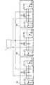
- FIG. 3 schematically shows another configuration example of the fluorine gas generation device 100, which is different from FIG.
- one power supply device 9A or 9B is connected to each of the electrolytic cell units 50A and 50B.
- power may be supplied from one power supply device 9 to the plurality of electrolytic cells.
- three electrolytic cell units 50A to 50C are connected in parallel to one power supply device 9 connected to the controller 10.
- the controller 10 controls the outputs from the power supply devices 9A and 9B in voltage.
- the fluorine gas generation device of the present embodiment determines a total current value to be supplied to the plurality of electrolytic cells, and supplies each electrolytic cell based on the determined total current value. Adjust the output voltage.
- the fluorine gas generation device of the present embodiment can stably supply fluorine gas.
- the controller 10 increases or decreases the voltage supplied to the plurality of electrolytic cells in the same direction based on the determined total current value. Thereby, it can prevent more appropriately that corrosion advances greatly only in the specific electrolytic cell in a plurality of electrolytic cells.
- the controller 10 adjusts the voltage output to each of the plurality of electrolytic cells so that the ratio of the voltage values output to the plurality of electrolytic cells is constant.
- the voltage value output from the power supply device 9A to the electrolytic cell 1A is V1
- the voltage output from the power supply device 9B to the electrolytic cell 1B is V2
- the controller 10 has a constant ratio of V1 and V2.
- the power supply devices 9A and 9B are controlled as shown.
- the ratio between V1 and V2 may be determined in accordance with, for example, the ratio of the electrolytic areas of the anodes 7A and 7B between the electrolytic cells 1A and 1B (for example, they match). In the control of three or more electrolytic cells, the ratio between different electrolytic cell pairs is the same or different.
- the controller 10 may control the power supply device so that the amount of increase or decrease in the voltage value output to the plurality of electrolytic cells is the same.
- the same or different reference voltage values are defined for the plurality of electrolytic cells, and the controller 10 changes the voltage output to the plurality of electrolytic cells by the same amount from the reference voltage value, and outputs the voltage between the electrolytic cells.
- the difference in voltage output voltage is constant. When the difference is 0, the output voltage values to the two electrolytic cells are the same. In the control of three or more electrolytic cells, the difference between different electrolytic cell pairs is the same or different.
- the fluorine gas can be generated without greatly increasing only the load applied to some electrolytic cells without requiring a complicated control configuration. It can be supplied automatically and stably.
- outputs from one power supply device 9 to all the electrolytic cell units 50A to 50C are parallel, and all output voltages are the same.
- the voltage value ratio between the electrolytic cells is 1 or the difference is 0.
- the controller 10 outputs a control signal to each power supply device so that the voltage value output from the power supply device to the electrode pair of the electrolytic cell is the same in all electrolytic cells.
- the supply of fluorine gas from the fluorine gas generator 100 is not stopped. Only the electrolytic cell unit corresponding to the cancellation may be stopped. In this case, the same voltage is applied only to the electrode pair of an electrolytic cell (electrolytic cell used for generating fluorine gas) other than the electrolytic cell unit corresponding to the suspension of use.
- the controller 10 uses data (pressure and flow rate) detected by a pressure gauge 24 that monitors the pressure of the buffer tank 21 and a flow meter 26 that monitors the flow rate downstream of the buffer tank 21 in the first main passage 15. Based on the calculated current value and the operator input value (parameter), a current value required for electrolysis (total current value for a plurality of electrolytic cells) is calculated, and the calculated value and each electrolytic cell 1A, 1B are calculated. The voltage output from the power supply devices 9A and 9B is controlled by comparison with the sum of the current values actually energized.
- the controller 10 detects the flow rate of the fluorine gas supplied from the fluorine gas generation device 100 to the external device 4 by the flow meter 26, and generates the fluorine gas that maintains the detected flow rate from the detection result according to the above equation 1.
- a current value (target current value) necessary for electrolysis for performing the calculation is calculated.
- the ROM of the controller 10 stores the following formula 2 obtained by modifying the formula 1 with the current efficiency in the formula 1 set to 95%.
- the controller 10 calculates a target current value in accordance with the formula 2.
- the minimum current value is set for the target current value.
- the minimum current value is set based on a preset minimum current density value.
- the current density is obtained by dividing the current value by the electrolytic area of the anode 7 installed in the electrolytic cell 1.
- the minimum current density is set When a 0.5A / dm 2, when the electrolytic area of the anode is 10 dm 2, the minimum current value is 5A. Accordingly, the power supply devices 9A and 9B are controlled so that the target current value does not become 0A even when the flow rate detected by the flow meter 26 is 0 L / min. However, when the flow rate detected by the flow meter 26 continues 0 L / min for a certain time or more, the power supply devices 9A and 9B are controlled so that the target current value becomes 0A.
- the controller 10 detects the pressure in the buffer tank 21 with the pressure gauge 24, and calculates a correction current value from the target current value or other preset current value based on the detection result.
- a plurality of pressure ranges are defined in advance for the detected pressure in the pressure gauge 24.
- the pressure is divided into six pressure ranges (sections), and sections 1 to 6 are defined in descending order of pressure.
- the pressure range of section 1 is the highest and the pressure range of section 6 is the lowest.
- the range of the pressure range is determined by the capacity and pressure resistance of the buffer tank 21 and the capacity of the booster pump included in the booster 17.
- a correction current value calculation method is defined for each section.
- An example of the calculation method of the correction current value in each section is as follows.
- Category 1: Correction current value Electrolysis stop (0A)
- Category 2: Correction current value Minimum current value
- Category 3: Correction current value Target current value x 90%
- Category 4: Correction current value Target current value
- Category 5: Correction current value Target current value ⁇ 110%
- Category 6: Correction current value Maximum current value of the fluorine gas generator 100
- the controller 10 compares the detection result of the pressure gauge 24 with each section, and specifies the section including the detection result.
- the controller 10 calculates the correction current value according to the calculation method associated with the identified category.
- the “maximum current value of the fluorine gas generation device 100” in the calculation method defined for the category 6 is determined by the specifications of each device such as the electrolytic cells 1A and 1B and the power supply devices 9A and 9B included in the fluorine generation device 100. This is the upper limit of the current value calculated by multiplying the design capability of the fluorine generator 100 by a certain safety factor.
- the safety factor is determined based on the design guidelines of the fluorine gas generation device 100. In addition, if there is an electrolytic cell whose use is suspended due to circumstances such as the above-mentioned maintenance or emergency, according to the situation, The timely safety factor is changed. For example, when a fluorine gas generation device including three electrolytic cells is designed with a safety factor of 75%, the maximum current value when the three electrolytic cells are operating is the design capacity of the fluorine gas generation device x 75%. When one of the three electrolytic cells needs to be stopped due to maintenance, the safety factor is changed to 2/3 of 75%, that is, 50%, and the maximum current value is a fluorine gas generator. The design ability is calculated as 50%.
- the upper limit value of the target flow rate of fluorine gas that can be changed by the operator who operates the fluorine gas generation device 100 is also changed according to the maximum current value. Specifically, a flow rate calculated by inputting the maximum current value of the fluorine gas generation device 100 to the current value of Equation 2 described above is captured (stored) in the controller 10 as the upper limit value of the target flow rate, and this calculation is performed. When the flow rate value input by the operator is larger than the upper limit value of the target flow rate, the controller 10 automatically changes the flow rate value input by the operator to the upper limit value of the target flow rate.
- the controller 10 calculates the actual current value and the current deviation range in parallel with the calculation of the correction current value. Specifically, the controller 10 takes in the data of the current values energized from each of the power supply devices 9A and 9B included in the fluorine gas generation device 100 from the power supply devices 9A and 9B, and sums them. (Total current value) is stored in the RAM as an actual current value. For example, the controller 10 calculates 2% of the maximum current value of the fluorine gas generation device 100 as the current deviation range, and stores the value in the ROM.
- the controller 10 compares the calculated correction current value with the actual current value.
- the controller 10 starts to decrease the voltage value output from each power supply device 9A, 9B to each electrolytic cell 1A, 1B.
- the decreasing speed of the voltage value varies depending on the configuration of the electrolytic cells 1A and 1B and the capacity of the entire fluorine gas generation apparatus 100.
- the controller 10 calculates an appropriate speed in advance and reduces the voltage at that speed.
- Controller 10 compares the corrected current value and the actual current value at all times or at regular intervals, and adjusts the adjustment of the voltage value.
- the length of the cycle depends on the specification of the fluorine gas generation device 100 itself and the usage environment. For example, the period is set to less than 10 minutes.
- the pressure fluctuation of the buffer tank 21 occurs due to the difference between the flow rate of the fluorine gas supplied to the external device 4 and the flow rate of the fluorine gas generated in the electrolytic cells 1A and 1B. It may be difficult to keep the pressure within an appropriate range.
- the controller 10 may adjust the output voltages of the power supply devices 9A and 9B by other methods. For example, the controller 10 calculates the resistance value of each electrolytic cell from the current value and the voltage value before the voltage change is started, and the actual current value (the sum of the current values of the electrolytic cells 1A and 1B) is calculated using the calculated value. An estimated voltage value that matches the corrected current value is calculated. After the change to the voltage value, the controller 10 confirms the actual current value, and adjusts the output voltage value by the above method according to the difference between the actual current value and the correction current value.
- the current value supplied between the anode and the cathode from the power supply device is calculated based on the flow rate of fluorine gas supplied from the buffer tank to the external device, and the calculated current value By correcting based on the pressure in the buffer tank, fluorine gas can be supplied to an external device more stably.
- the purification device 16 is installed in the first main passage 15, but for the purpose of reducing the size of the purification device, the same number of purification devices as the electrolytic cell units are prepared, and the main gas derived from each electrolytic cell is derived. Each may be installed on the route. If the purity of the fluorine gas in the generated main gas is not an industrial problem, it is not necessary to install a purifier.
- the corrected current value is determined based on the amount of gas generated by a plurality of electrolytic cells (the amount of fluorine gas after purification in the above example) with reference to the detection values of the flow meter and the pressure gauge.
- the present invention can be applied to a fluorine gas generator that does not have a buffer tank.
- the controller monitors the flow rate of fluorine gas (one value representing the amount of gas generated by a plurality of electrolytic cells) supplied to the external device, and outputs the flow rate to each electrolytic cell so that the flow rate approaches the reference value. Adjust the voltage.
- the controller does not use the pressure detection value in the main passage, adjusts the voltage output to each electrolytic cell using the detected gas flow value, and does not refer to the fluorine gas flow rate, and detects in the buffer tank.
Landscapes
- Chemical & Material Sciences (AREA)
- Organic Chemistry (AREA)
- Engineering & Computer Science (AREA)
- Inorganic Chemistry (AREA)
- Chemical Kinetics & Catalysis (AREA)
- Electrochemistry (AREA)
- Materials Engineering (AREA)
- Metallurgy (AREA)
- Automation & Control Theory (AREA)
- Electrolytic Production Of Non-Metals, Compounds, Apparatuses Therefor (AREA)
Abstract
L'invention concerne un appareil de production de gaz fluor en soumettant un composé fluor à une électrolyse dans un bain électrolytique. L'appareil de production de gaz fluor comprend une pluralité de cuves électrolytiques, chacune desquelles comprend un bain électrolytique comprenant un composé fluor, ainsi qu'une électrode positive et une électrode négative qui sont insérées dans le bain électrolytique, les cuves électrolytiques produisant du gaz fluor par soumission du composé fluor dans le bain électrolytique à une électrolyse en utilisant un courant circulant entre l'électrode positive et l'électrode négative. Une unité de commande détermine la totalité du courant appliqué à la pluralité de cuves électrolytiques en conformité avec la quantité de gaz comprenant du gaz fluor qui est produit par la pluralité de cuves électrolytiques, et commande la tension de sortie de la source d'alimentation de telle sorte que la valeur de la tension appliquée à la pluralité de cuves électrolytiques augmente ou diminue dans la même direction en conformité avec le résultat de la comparaison du courant total déterminé et du courant total appliqué à la pluralité de cuves électrolytiques qui a été détecté.
Applications Claiming Priority (2)
| Application Number | Priority Date | Filing Date | Title |
|---|---|---|---|
| JP2012-178055 | 2012-08-10 | ||
| JP2012178055A JP5991070B2 (ja) | 2012-08-10 | 2012-08-10 | フッ素ガス生成装置及びフッ素ガス生成装置の制御方法 |
Publications (1)
| Publication Number | Publication Date |
|---|---|
| WO2014024660A1 true WO2014024660A1 (fr) | 2014-02-13 |
Family
ID=50067894
Family Applications (1)
| Application Number | Title | Priority Date | Filing Date |
|---|---|---|---|
| PCT/JP2013/069596 WO2014024660A1 (fr) | 2012-08-10 | 2013-07-19 | Appareil de production de gaz fluor et son procédé de commande |
Country Status (3)
| Country | Link |
|---|---|
| JP (1) | JP5991070B2 (fr) |
| TW (1) | TW201413059A (fr) |
| WO (1) | WO2014024660A1 (fr) |
Cited By (1)
| Publication number | Priority date | Publication date | Assignee | Title |
|---|---|---|---|---|
| CN111850597A (zh) * | 2020-06-15 | 2020-10-30 | 中船重工(邯郸)派瑞特种气体有限公司 | 一种电化学氟化外循环电解系统 |
Families Citing this family (2)
| Publication number | Priority date | Publication date | Assignee | Title |
|---|---|---|---|---|
| JP6605884B2 (ja) * | 2014-09-02 | 2019-11-13 | 株式会社東芝 | 水素製造システム及び水素製造方法 |
| DE102020115711A1 (de) * | 2020-06-15 | 2021-12-16 | Thyssenkrupp Uhde Chlorine Engineers Gmbh | Verfahren zur bedarfsabhängigen Regelung einer elektrochemischen Anlage |
Citations (3)
| Publication number | Priority date | Publication date | Assignee | Title |
|---|---|---|---|---|
| JP2005194564A (ja) * | 2004-01-06 | 2005-07-21 | Sumitomo Chemical Co Ltd | 電気分解生成物の製造方法 |
| JP2011225920A (ja) * | 2010-04-16 | 2011-11-10 | Central Glass Co Ltd | フッ素ガス生成装置 |
| JP2012017520A (ja) * | 2010-07-07 | 2012-01-26 | E & E Corp | ブラウンガス製造装置およびブラウンガス製造方法 |
Family Cites Families (1)
| Publication number | Priority date | Publication date | Assignee | Title |
|---|---|---|---|---|
| JP2010189675A (ja) * | 2009-02-16 | 2010-09-02 | Toyo Tanso Kk | 気体発生装置および気体発生方法 |
-
2012
- 2012-08-10 JP JP2012178055A patent/JP5991070B2/ja active Active
-
2013
- 2013-07-19 WO PCT/JP2013/069596 patent/WO2014024660A1/fr active Application Filing
- 2013-08-06 TW TW102128157A patent/TW201413059A/zh unknown
Patent Citations (3)
| Publication number | Priority date | Publication date | Assignee | Title |
|---|---|---|---|---|
| JP2005194564A (ja) * | 2004-01-06 | 2005-07-21 | Sumitomo Chemical Co Ltd | 電気分解生成物の製造方法 |
| JP2011225920A (ja) * | 2010-04-16 | 2011-11-10 | Central Glass Co Ltd | フッ素ガス生成装置 |
| JP2012017520A (ja) * | 2010-07-07 | 2012-01-26 | E & E Corp | ブラウンガス製造装置およびブラウンガス製造方法 |
Cited By (2)
| Publication number | Priority date | Publication date | Assignee | Title |
|---|---|---|---|---|
| CN111850597A (zh) * | 2020-06-15 | 2020-10-30 | 中船重工(邯郸)派瑞特种气体有限公司 | 一种电化学氟化外循环电解系统 |
| CN111850597B (zh) * | 2020-06-15 | 2022-08-05 | 中船(邯郸)派瑞特种气体股份有限公司 | 一种电化学氟化外循环电解系统 |
Also Published As
| Publication number | Publication date |
|---|---|
| JP2014034726A (ja) | 2014-02-24 |
| JP5991070B2 (ja) | 2016-09-14 |
| TW201413059A (zh) | 2014-04-01 |
Similar Documents
| Publication | Publication Date | Title |
|---|---|---|
| JP5569116B2 (ja) | フッ素ガス生成装置 | |
| TWI822978B (zh) | 水電解裝置的功能回復方法以及水電解裝置 | |
| KR20080050380A (ko) | 전기분해식차아염소산나트륨발생시스템 | |
| JP5991070B2 (ja) | フッ素ガス生成装置及びフッ素ガス生成装置の制御方法 | |
| WO2018155308A1 (fr) | Système d'électrolyse de l'eau et procédé d'exploitation de système d'électrolyse de l'eau | |
| KR20160100299A (ko) | 전력의 유연한 사용을 위한 디바이스 및 방법 | |
| TW201235511A (en) | Electrolyzer apparatus | |
| JP2017064595A (ja) | 電解次亜水生成装置 | |
| US7288180B2 (en) | Electric current control method and apparatus for use in gas generators | |
| JP5720112B2 (ja) | フッ素ガス生成装置 | |
| JP2018183740A (ja) | 電解水生成装置 | |
| JP5933057B2 (ja) | 三フッ化窒素の効率的な製造のための電解装置、システム及び方法 | |
| JP5906742B2 (ja) | フッ素ガス生成装置 | |
| JP2008231537A (ja) | 電解シミュレーション装置 | |
| WO2018174034A1 (fr) | Dispositif de génération d'eau électrolysée et procédé de génération d'eau électrolysée | |
| JP5375673B2 (ja) | フッ素ガス生成装置 | |
| JP2009191362A (ja) | 溶融塩電解装置及びフッ素ガスの発生方法 | |
| JP2014034726A5 (fr) | ||
| JP5567375B2 (ja) | 気体発生装置および気体発生方法 | |
| JP5716288B2 (ja) | フッ素ガス生成装置 | |
| JP6810112B2 (ja) | 電解水生成装置及び電解水生成方法 | |
| TW201713169A (zh) | 補償電極改變而供應至電漿炬之電力控制 | |
| JP2003268585A (ja) | 水電解装置とその運転方法 | |
| JPS5835274B2 (ja) | アルミニウムデンカイソウノセイギヨホウホウ | |
| JP2007061766A (ja) | 電解水生成装置 |
Legal Events
| Date | Code | Title | Description |
|---|---|---|---|
| 121 | Ep: the epo has been informed by wipo that ep was designated in this application |
Ref document number: 13828410 Country of ref document: EP Kind code of ref document: A1 |
|
| NENP | Non-entry into the national phase |
Ref country code: DE |
|
| 122 | Ep: pct application non-entry in european phase |
Ref document number: 13828410 Country of ref document: EP Kind code of ref document: A1 |