WO2014024264A1 - 交通量予測装置および方法 - Google Patents
交通量予測装置および方法 Download PDFInfo
- Publication number
- WO2014024264A1 WO2014024264A1 PCT/JP2012/070142 JP2012070142W WO2014024264A1 WO 2014024264 A1 WO2014024264 A1 WO 2014024264A1 JP 2012070142 W JP2012070142 W JP 2012070142W WO 2014024264 A1 WO2014024264 A1 WO 2014024264A1
- Authority
- WO
- WIPO (PCT)
- Prior art keywords
- traffic volume
- traffic
- intersections
- main
- route
- Prior art date
- Legal status (The legal status is an assumption and is not a legal conclusion. Google has not performed a legal analysis and makes no representation as to the accuracy of the status listed.)
- Ceased
Links
Images






Classifications
-
- G—PHYSICS
- G08—SIGNALLING
- G08G—TRAFFIC CONTROL SYSTEMS
- G08G1/00—Traffic control systems for road vehicles
- G08G1/01—Detecting movement of traffic to be counted or controlled
- G08G1/0104—Measuring and analyzing of parameters relative to traffic conditions
- G08G1/0125—Traffic data processing
- G08G1/0129—Traffic data processing for creating historical data or processing based on historical data
-
- G—PHYSICS
- G08—SIGNALLING
- G08G—TRAFFIC CONTROL SYSTEMS
- G08G1/00—Traffic control systems for road vehicles
- G08G1/01—Detecting movement of traffic to be counted or controlled
- G08G1/0104—Measuring and analyzing of parameters relative to traffic conditions
- G08G1/0108—Measuring and analyzing of parameters relative to traffic conditions based on the source of data
- G08G1/0112—Measuring and analyzing of parameters relative to traffic conditions based on the source of data from the vehicle, e.g. floating car data [FCD]
-
- G—PHYSICS
- G08—SIGNALLING
- G08G—TRAFFIC CONTROL SYSTEMS
- G08G1/00—Traffic control systems for road vehicles
- G08G1/01—Detecting movement of traffic to be counted or controlled
- G08G1/0104—Measuring and analyzing of parameters relative to traffic conditions
- G08G1/0137—Measuring and analyzing of parameters relative to traffic conditions for specific applications
- G08G1/0141—Measuring and analyzing of parameters relative to traffic conditions for specific applications for traffic information dissemination
Definitions
- the present invention relates to a traffic volume predicting apparatus, and more particularly to a traffic volume predicting apparatus that predicts a traffic volume between two points using a collected vehicle travel history.
- a route selection model In order to predict traffic demand, a route selection model is required.
- the route selection model assumes that the driver behaves based on a reasonable selection rule that selects the most desirable route from the set of available routes from the origin to the destination. This model calculates the selection probability of each route using factors such as distance and distance. The traffic volume on the route is predicted using the selection probability of each route.
- a route set In order to create this route selection model, a route set must be prepared in advance.
- Patent Document 1 describes a technique that uses probe data to create a route set of a route selection model. Since the probe data can specify the travel route of the vehicle, a route set can be easily created. Further, the route set is all the routes traveled by the probe car from the departure point to the destination.
- the driver selects a route from the departure point to the destination, the driver selects a route that is considered most desirable from the route set in the driver's head.
- the travel route of the probe data only represents the selected result, and the route set is insufficient. That is, with the technique described in Non-Patent Document 1, a route other than the route from the starting point of the probe data to the destination cannot be included in the route set. For this reason, it is not possible to obtain the traffic volume of a route having no running record.
- the traffic volume prediction device of the present invention is a simple network creation device that creates a simple network that connects main intersections with high travel frequency extracted from the travel trajectory of collected probe data;
- a model creation device that determines the utility between major intersections from the data and obtains the selection probability at each major intersection from this utility, and predicts traffic demand by allocating traffic according to this selection probability to the route between major intersections
- a traffic volume distribution device is provided for the traffic volume of each target route candidate.
- the network between the main intersections on the simple network can be combined according to the selection probability, it is possible to predict the traffic volume of the route having no running record.
- FIG. 3 is a diagram showing a data format of a storage device 120.
- FIG. It is an example of a simple network created by the simple network creation device. It is a figure which shows the processing flow of the simple network creation apparatus. It is a figure which shows the processing flow of the model production apparatus. It is a figure which shows the data format of OD traffic information. It is a figure which shows the data format of event information. It is a figure which shows the processing flow of the traffic volume estimation apparatus. It is a figure which shows the data format of the traffic volume of a virtual link unit. It is a figure which shows the data format of the traffic volume of a road link unit.
- FIG. 1 shows the overall configuration of a traffic demand prediction system according to an embodiment of the present invention.
- the traffic demand prediction system 100 in FIG. 1 includes a receiving device 110, a storage device 120, a simple network creation device 130, a model creation device 140, an input device 150, a traffic volume prediction device 160, and an output device 170.
- the receiving device 110, the simple network creation device 130, the model creation device 140, the input device 150, and the traffic volume prediction device 160 are executed by a microprocessor (not shown) mounted on the traffic demand prediction system 100, a RAM, a ROM, or the like.
- Software is not shown
- the receiving device 110 receives probe data transmitted from a probe center that collects and manages traveling information from the vehicle, and stores the probe data in the storage device 120.
- the probe data includes vehicle identification ID (hereinafter referred to as vehicle ID), position information composed of start / end node IDs for identifying roads on which the vehicle has traveled in units of links (segments), and time at which the vehicle traveled on the link. Information, travel time information that is the time required for passing the link, and travel distance information that is the distance traveled by the link.
- the vehicle receives the vehicle ID, the position information of the traveling position of the vehicle, the time information that is the time when the vehicle was traveling, and the travel time information after the start of traveling via the communication device such as a mobile phone or a wireless device.
- a vehicle that provides such travel information is called a probe car.
- the road on which the vehicle has traveled is specified using position information and time information from the travel information collected from the probe car and map information mounted on the probe center.
- the probe data received by the receiving device 110 is data processed at the probe center.
- the storage device 120 is composed of a storage device such as a hard disk or a flash memory, and stores probe data, simple network data, and selected model data.
- the probe data is data input from the receiving device 110.
- the simple network data is data input from the simple network creation device 130.
- the selected model data is data input from the model creation device 140.
- the format of probe data received by the receiving device 110 is shown in FIG.
- the probe data includes a vehicle ID (21) for identifying the vehicle from which the probe data has been collected, a road start point node ID (22) and an end point node ID (23) for identifying the road from which the probe data has been collected, Is an inflow time (24) which is the time when the vehicle enters the road, a travel time (25) when the vehicle passes the road, and a travel distance (26).
- the simple network creation device 130 uses the probe data stored in the storage device 120 to extract major intersections and creates a simple network connecting the major intersections.
- the created simple network data is stored in the storage device 120. Details of the simple network creation device 130 will be described later.
- the model creation device 140 calculates the utility function of each major intersection using the probe data and simple network data stored in the storage device 120.
- the utility function generally has a preference relationship that favors the other of the two selection targets over one of the selection targets, and is equivalent to a magnitude relationship based on the value of the function that represents the utility (or value) of these selection targets.
- the function represents the relationship between the factors such as the time and distance between the main intersections and the utility between the main intersections.
- the created utility function data is stored in the storage device 120 as selected model data. Details of the model creation device 140 will be described later.
- the input device 150 receives from the user or an external center the starting point and destination of the traffic estimation target, the traffic from the starting point to the destination (hereinafter referred to as OD traffic), and event information assumed between the starting point and the destination. Enter.
- the traffic demand prediction system 100 is used to predict a change in traffic volume when a certain event occurs. As the conditions for the prediction, the input device 150 inputs the target area of the departure point and the destination, OD traffic volume, and assumed event information. The input information is provided to the traffic volume prediction device 160. Details of the input device 150 will be described later.
- the traffic volume prediction device 160 predicts the traffic volume at the time of the event occurrence using the conditions input from the input device 150, the simple network data of the storage device 120, and the selected model data. The predicted traffic volume is provided to the output device 170. Details of the traffic volume prediction device 160 will be described later.
- the output device 170 outputs the predicted traffic volume of the traffic volume prediction device 160 to the user or an external center. Details of the output device 170 will be described later.
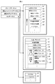
- the data format of various data stored in the storage device 120 is shown in FIG.
- the storage device 120 stores probe data (a), simple network data (b), selection model data (c), and OD data (d).
- the data format of the probe data (a) is the same as the format of the probe data received by the receiving apparatus 110 (FIG. 2).
- the simple network data (b) includes, for each combination of the departure point (b1) and the destination (b2), the node ID (b3) of the main intersection serving as the start point, the node ID (b4) of the main intersection serving as the end point, and the main intersection
- the simple network data (b) is created by the simple network creation device 130.
- the selection model data (c) is data representing the parameters in the route selection model and their reliability, and is created by the model creation device 140.
- the selection model data (c) includes common data that does not depend on the departure place and the destination, and data for each departure place and the destination.
- the common data that does not depend on the starting point and the destination is the common parameter (c1) that expresses the route selection model representing the route selection behavior for various combinations of the starting point and the destination, and the common trust that is the reliability of the parameter.
- Degree (c2) For each combination of the departure place and the destination, the data of the departure place and the destination are the departure area ID (c3) that is the area ID of the departure place, the destination area ID (c4) that is the area ID of the destination, and the route.
- an individual parameter (c5) that is an individual parameter in the selection model
- an individual reliability (c6) that is the reliability of the individual parameter.
- a plurality of model parameters created by the model creation device 140 for each combination of starting point and destination, a plurality of values are generally set as common parameters (c1) and individual parameters (c5). Have. Therefore, there are a plurality of common parameters (c2) and individual parameters (c5) as parameters of the route selection model.
- the parameter reliability is an index indicating how reliable the parameter is, and corresponds to the parameter on a one-to-one basis.
- the individual parameter (c5) includes a time parameter (c7) and a distance parameter (c8)
- the individual reliability (c6) is , Time parameter reliability (c9) and distance parameter reliability (c10).
- the OD data (d) stores information on the starting point and destination of traffic demand prediction.
- the OD data (d) is composed of an area ID (d1) for identifying an area where a departure place or a destination is defined, and a node ID list (d2) included in the area.
- the node ID list (d2) of the administrative unit serving as the departure point or destination for example, Hitachi City
- the OD data (d) is created in advance at the time of server shipment, or is created at regular time intervals.
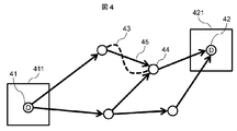
- FIG. 4 shows an example of a simple network.
- the sizes of the departure point (41) and the destination (42) vary depending on the purpose of traffic demand prediction. For example, when it is desired to predict traffic demand at the municipal level, the starting point and destination are in units of municipalities such as Hitachi City and Mito City. In the following, the starting point and the destination are defined by a map mesh.
- the probe data traveling from the departure point (41) to the destination (42) is extracted from the storage device 120, and the main intersection (44) among the intersections with a large traffic volume based on the traveling history (43) of the extracted probe data. To extract.
- a simple network representing a section where the probe car actually traveled from the starting point (41) to the destination (42) can be created.
- this virtual link is not necessarily a road that actually exists, but is a line segment that connects the main intersections that exist at both ends of the road (43) that has actually run.
- the simple network creation device 130 processes the probe data (a) accumulated in the storage device 120 at a regular cycle such as one month or one year. Each step will be described in detail below.
- step S510 processing for repeating the processing from step S520 to S540 is started for all combinations of area IDs stored in the OD data (d) of the storage device 120.
- one of the area IDs stored as the OD data (d) in the storage information 120 is set as the departure place, and the area ID of this departure place among the area IDs stored as the OD data (d).
- One of the other area IDs is the destination.
- n areas are defined in the OD data (d) of the storage device 120, the total number of combinations of the area IDs of the departure point and the destination is n ⁇ (n ⁇ 1).
- the following loop processing is performed for all combinations of the departure area and destination area IDs thus obtained.
- step S520 probe data traveling from the departure point to the destination determined in step S510 is extracted from the probe data (a) in the storage device 110. If there is no probe data traveling from the target departure point to the destination, the subsequent main intersection extraction step S530 and network creation step S540 are substantially skipped, but the processing of FIG. In the flow, this process flow is simplified.
- step S530 the main intersection is extracted using the probe data extracted in step S520.
- the main intersection is a high frequency of probe car travel, a lot of traffic flowing into the intersection, and the traffic flowing in is widely distributed over multiple roads connected to the intersection. It means an intersection that is not concentrated and flowing out.
- the degree of branching of the traffic flowing into each intersection is calculated using the probe data extracted in step S520.
- a quantitative index representing the degree of branching is defined as the degree of branching. An intersection with a large branching degree indicates that the probe car that has flowed into the intersection is likely to branch to various roads at the intersection.
- This branching degree is created for each node that flows into the intersection.
- the degree of branching is defined as the number of inflows divided by the maximum number of outflows. For example, consider a case where an intersection flows in from node ID “001” and flows out to node IDs “002”, “003”, and “004”. The number of vehicles flowing into the intersection from the node ID “001” is 100, the number of vehicles flowing out to the node “002” is 50, the number of vehicles flowing out to the node “003” is 30, and the vehicle flows out to the node “004”. The number of vehicles is 20.
- the branching degree is 2.0 (100/50).
- the degree of branching is 1.0 (100 / 100).
- the degree of branching at an intersection can be evaluated by the degree of branching.
- This branching degree is created for each inflow node of each intersection node.
- a combination of an intersection node and an inflow node that is equal to or greater than the threshold is defined as a main intersection by using a preset branching degree threshold.
- step S540 probe data traveling between the main intersections extracted in step S530 is extracted from the probe data extracted in step S520.
- Probe data traveling between major intersections is extracted, and virtual links are created between major intersections.
- the number of probe cars traveling between the main intersections (b5), the average travel time (b6) to the destination and the average travel distance (b7) obtained from the probe data for each virtual link The value is written into the simple network data (b) of the storage device 120. Further, the departure area ID and the destination area ID determined in step S510 are written as the departure area ID (b1) and the destination area ID (b2), respectively, and the main intersection (starting main intersection) serving as the starting point of the virtual link is written.
- the node ID is the start node ID (b3)
- the node ID of the main intersection (end point main intersection) that is the end point of the virtual link is the end node ID (b4)
- the list of node IDs between the main intersections obtained from the probe data is the node list As (b8), the simple network data (b) of the storage device 120 is written.
- the node list (b8) includes the node IDs of all the nodes that have passed between the main intersections in the probe data that has passed between the start point main intersection and the end point main intersection of the virtual link.
- step S550 it is determined whether or not the processing has been completed for all combinations of the departure point and the destination, and the processing flow ends when the processing is completed. If the processing has not been completed for all combinations of departure points and destinations, the loop processing returning to step S510 is continued.
- the model creation device 140 performs processing for generating parameters describing the route selection model using the probe data (a) and the simple network data (b) in the storage device 120.
- the vehicle When there are a plurality of virtual links connected to the main intersection as a starting point, the vehicle obtains the utility of each virtual link from the characteristics of the virtual link, and selects the virtual link based on this utility and travels Assume that An expression that associates the characteristics and utility of a virtual link is a utility function.
- This utility function is an evaluation function for determining the probability of selecting a virtual link, which means that the driver (vehicle) is evaluating the degree of attractiveness that the driver feels for the route between the virtual links. The virtual link selection probability is high.
- the characteristics of the virtual link are the average travel time (b6) and the average travel distance (b7) of the simple network data (b) in the storage device 120.
- the starting point node ID of the starting point main intersection is “i”
- the end point node ID of the end point main intersection of the virtual link connected to the starting point main intersection node ID “i” is “j”.
- the utility of the virtual link “ij” defined by the start node ID “i” and the end node ID “j” is “Vij”.
- the average travel time (b6) of the virtual link “ij” is “Tij” and the average travel distance (b7) of the virtual link “ij” is “Lij”.
- the travel time parameter in the utility function is “ ⁇ tij” and the travel distance parameter in the utility function is “ ⁇ lij”
- the utility function is defined by (Equation 1).
- Vij ⁇ tij ⁇ Tij + ⁇ lij ⁇ Lij (Formula 1)
- This utility function is preset by the system manufacturer or user. For this reason, in addition to (Equation 1), characteristics such as expenses due to tolls and road widths may be considered.
- the model creation device 140 estimates the parameters of the utility function and stores the estimated results in the selection model data (c) of the storage device 120 as the parameters of the route selection model.
- the parameters of the selection model are created for each combination of the departure area and the destination area. That is, if the departure area and the destination area are determined, there is one parameter.
- the parameters are estimated for each combination of the departure area and the destination area in steps S610 to S680. However, depending on the combination of the departure area and the destination area, the number of probe data samples is small, so the parameter reliability may be low. For this reason, a common parameter is estimated using all the probe data without depending on the combination of the departure area and the destination area. This common parameter is used instead when the reliability of the parameters of the departure area and the destination area is low. This process is step S690.
- step S610 a process of repeating the processes from step S620 to S670 is started for all combinations of area IDs stored in the OD data (d) of the storage device 120.
- step S510 one of the area IDs in the OD data (d) of the stored information 120 is set as the departure point, and one of the plurality of area IDs other than the area ID of the departure point is set as the destination.
- a combination of the departure area ID and the destination area ID is determined. If n area IDs are defined in the OD data (d) of the storage device 120, the total number of combinations is n ⁇ (n ⁇ 1).
- step S620 simple network data corresponding to the departure area ID and destination area ID determined in step S610 is extracted from the simple network data (b) in the storage device 120.
- step S630 the process of step S640 is repeated for all start point node IDs (d3) of the simple network data (b) extracted in step S620.
- step S640 the simple network data (b) including the start node ID (d3) to be processed in the loop processing in step S630 is extracted, and the extracted data is set in the utility function expression defined in (Expression 1). To create a utility function.
- step S650 it is determined whether or not the process has been completed for all the start point node IDs. If the process is completed, the process proceeds to step S660. If the process has not been completed for all start point node IDs, the process returns to step S630.
- step S660 a likelihood function is created using the utility function created in step S640.
- One likelihood function is created for every combination of area IDs in step S610.
- the traveling number (b5) of the probe cars of the virtual link “ij” is “nij”
- the likelihood function Li of the start node ID “i” is connected to the main intersection node “i” as shown in (Equation 2). Expressed as the sum for all major intersection nodes “j”.
- Li ⁇ (nij ⁇ log (Pij)) (Formula 2) This “Pij” is the probability of selecting the virtual link “ij”, and is obtained as in (Expression 3) using the utility “Vij” in (Expression 1).
- the likelihood function “Lod” for each combination of area IDs is expressed as (Equation 4) in which all the likelihoods of the main intersection node “i” between the departure point and the destination are obtained.
- step S670 the parameters “ ⁇ tij” and “ ⁇ lij” in (Expression 1) are estimated so that the likelihood function Lod created in step S660 is maximized.
- an existing maximum likelihood estimation method is used.
- the parameter obtained by the maximum likelihood estimation is stored in a location corresponding to the combination of area IDs in step S610 of the selection model data (c) of the storage device 120.
- the travel time parameter “ ⁇ tij” is the time parameter (c7) of the selection model data (c) of the storage device 120
- the distance parameter is “ ⁇ lij” is the distance of the selection model data (c) of the storage device 120.
- the calculated reliability is stored in the individual reliability (c6) of the selection model data (c) in the storage device 120.
- step S680 it is determined whether or not the process has been completed for all combinations of area IDs stored in the OD data (d) of the storage device 120. If the process is completed, the process proceeds to step S690. If the process has not been completed for all combinations of area IDs, the process returns to step S610.
- step S690 parameters that do not depend on the combination of area IDs are estimated. Specifically, the parameters are estimated using the existing maximum likelihood estimation method so that the sum of the likelihood function “Lod” for each combination of area IDs is maximized, thereby obtaining each combination of area IDs. A parameter based on a common likelihood that is not a parameter is obtained. The estimated parameter is stored in the common parameter (c1). Similarly, the reliability of this parameter is obtained in the same manner as in the case of the individual reliability, and stored in the shared reliability (c2).
- the input device 150 receives OD traffic volume information and event information that are traffic volume estimation targets. Input is performed from a user or an external server.
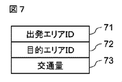
- the data format of the OD traffic information input to the input device 150 is shown in FIG.
- the OD traffic information includes departure area ID (71), which is an area ID for specifying a departure place, destination area ID (72), which is an area ID for specifying a destination, as departure point and destination information. It is composed of the traffic volume (73) traveling from the destination to the destination.
- the data format of event information input from the input device 150 is shown in FIG.
- the event information includes an event name (81) for identifying the event, an event occurrence position (82), and an influence after the event occurrence (83).
- An example of the event name (81) is “construction”.
- the event occurrence position (82) describes a node ID where the event occurs and a start node ID and an end node ID that identify the road. When an event extends over a plurality of nodes, a plurality of node IDs are described.
- the influence (83) after the occurrence of an event represents a change in the traffic situation at the event occurrence location when the event occurs. For example, when construction is performed, the passing time is doubled on the construction target road.
- the event name (81) of the event information is “construction”
- the event occurrence position (82) is the start node ID and the end node ID
- the influence (83) after the event occurrence in the work section is “Twice the transit time” is described.
- the event name (81) is “road pricing”
- the event occurrence location (82) is the start node ID and end node ID of the road pricing target road
- data such as “billing 1000 yen” is input as event information.
- the traffic volume prediction device 160 uses the simple network data (b) and selection model data (c) stored in the storage device 120, the OD traffic volume information and the event information input via the input device 150, and the road after the occurrence of the event. Predict traffic volume.
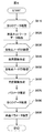
- a processing flow of the traffic volume prediction device 160 will be described with reference to FIG.
- the traffic volume prediction device 160 performs processing based on OD traffic volume information and event information input from the input device 150.
- step S910 the simplified network data (b) corresponding to the combination of the departure area ID (71) and the destination area ID (72) in the OD traffic information from the input device 150 is acquired from the storage device 120.
- step S920 the parameter of the selected model data (c) corresponding to the combination of the departure area ID (71) and the destination area ID (72) in the OD traffic information from the input device 150 is acquired from the storage device 120.
- the individual parameter (c5) for each departure area ID (c3) and destination area ID (c4) is acquired.
- the individual reliability (c6) of the individual parameter (c5) is lower than a preset threshold, the common parameter (c1) is acquired.
- step S930 using the event information from the input device 150, for each main intersection node included in the simple network represented by the simple network data (b) acquired in step S910, a virtual connected to the main intersection node.
- the event information is “construction”
- the event occurrence position is the road from the start node ID “001” to the end node ID “002”.
- a virtual link including both the start node ID “001” and the end node ID “002” in the node list (b8) of the simple network data (b) extracted here is searched.
- the selection probability of each virtual link is calculated without reflecting the double effect of the required time, which is the influence of the event information.
- each selection probability is calculated by reflecting the influence of the required time that is the influence of the event information.
- the utility of each virtual link is first calculated by (Equation 1).
- the selection probability of each virtual link is calculated for all virtual links of the simple network data between the departure point and the destination using (Equation 3).
- step S940 loop processing for repeating the processing from step S950 to step S960 is started for the traffic volume (73) set by the OD traffic volume information from the input device 150. For example, when the traffic volume is 100, the processing from step S950 to step S960 is repeated 100 times. In this process, a simulation is performed to run a vehicle for the traffic volume on the simple network, and the traffic volume is obtained for each virtual link. This vehicle running simulation is assumed to run while selecting a virtual link according to the selection probability obtained in step S930.
- step S950 it is determined whether or not the vehicle simulating traveling in step S940 has arrived at the destination area.
- the vehicle to be processed is regarded as having arrived at the destination area from the departure area, and the process proceeds to step S970.
- step S960 If it has not arrived at the destination area (S950: No), the process proceeds to step S960.
- step S960 a virtual link connected to the main intersection node of the simple network to which the vehicle currently reaches is extracted, and the virtual link on which the vehicle travels is selected using the selection probability obtained in step S930.
- the virtual link is selected at random according to the selection probability.
- the position of the vehicle being simulated is advanced to the main intersection node at the end point of the selected virtual link. At this time, the number of vehicles traveling for each virtual link is stored in a temporary storage device.
- step S970 it is determined whether or not the processing for the traffic volume between the set ODs has been completed. If the processing has been completed, the process proceeds to step S970. If the processing for the OD traffic volume has not been completed, the process returns to step S940.
- step S980 the traffic information of each virtual link of the simple network stored in the temporary storage device in step S960 is acquired and provided to the output device 170. Also, the traffic volume of the virtual link is converted into the traffic volume of the actual road link corresponding to the virtual link. Specifically, using the node list (b8) of the simple network data (b) in the storage device 120, the traffic volume of the virtual link is converted into the corresponding road link as it is. However, when the virtual link and the road link sequence between them do not correspond one-to-one, the travel frequencies of a plurality of road link sequences corresponding to the virtual link are stored, and each road link is calculated by weighted average of the travel frequencies. Assign traffic to the columns. After the conversion, traffic volume information in units of road links is output to the output device 170.
- the input device 170 transmits the traffic volume in units of virtual links and the traffic volume in units of road links input from the traffic volume prediction device 160 to an external server or an in-vehicle terminal.
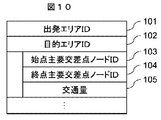
- FIG. 10 shows a traffic volume data format in units of virtual links.
- the virtual link traffic volume includes a departure area ID (101) that is an area ID for identifying a departure place, a destination area ID (102) that is an area ID for identifying a destination, and a traffic volume for each virtual link.
- the traffic volume for each virtual link is composed of the start point main intersection node ID (103), the end point main intersection node ID (104) of the virtual link, and the traffic volume (105) of the virtual link.
- Fig. 11 shows the traffic volume data format for each road link.
- the road link traffic volume includes a departure area ID (111), a destination area ID (112), and a traffic volume for each road link.
- the traffic volume for each road link includes a start node ID (113), an end node ID (114), and a road link traffic volume (115).
- the traffic demand prediction system of the present invention obtains a main intersection on the travel history of the probe car, creates a simple network connecting the main intersections, obtains a selection probability at each main intersection from the utility, and obtains a main intersection on the simple network. Since the traffic volume can be distributed to the links of the simple network according to the selection probability by combining the networks between them according to the selection probability, even the traffic volume of the route that does not actually have a continuous running track is predicted on the probe data it can.
Landscapes
- Chemical & Material Sciences (AREA)
- Analytical Chemistry (AREA)
- Physics & Mathematics (AREA)
- General Physics & Mathematics (AREA)
- Traffic Control Systems (AREA)
- Navigation (AREA)
Description
この効用関数はシステム製作者又はユーザーが予め設定する。このため、(式1)以外にも、通行料金などによる費用や道幅などの特性を考慮しても構わない。
この「Pij」は、仮想リンク「ij」を選択する確率であり、(式1)における効用「Vij」を用いて(式3)のように求められる。
ここでexp()は指数関数を表している。
ステップS670では、ステップS660で作成した尤度関数Lodが最大になるように(式1)のパラメータ「θtij」と「θlij」を推定する。この時の推定方法は、既存の最尤推定法を利用する。次に、最尤推定によって求められたパラメータは、記憶装置120の選択モデルデータ(c)のステップS610のエリアIDの組合せに該当する箇所に格納される。具体的には、旅行時間のパラメータ「θtij」を記憶装置120の選択モデルデータ(c)の時間パラメータ(c7)、距離のパラメータを「θlij」を記憶装置120の選択モデルデータ(c)の距離パラメータ(c8)に格納する。
110 受信装置
120 記憶装置
130 簡易ネットワーク作成装置
140 モデル作成装置
150 入力装置
160 交通量予測装置
170 出力装置
Claims (8)
- 予め収集した車両の走行軌跡データを使って地点間の交通量を予測する交通量予測装置であって、
走行軌跡データにおける走行経路上の交差点の内、走行軌跡の通過数に対する最大分岐数の割合に基づいて主要交差点を抽出して各主要交差点を結んだ簡易ネットワークを作るネットワーク作成装置と、
前記主要交差点間の特性値からこの主要交差点間の経路の効用を求め、前記効用を使って各主要交差点における選択確率を評価する経路選択モデルのパラメータを推定するモデル作成装置と、
推定された経路選択モデルのパラメータを用いて、主要交差点間の経路を選択する選択確率を求め、この選択確率に応じて交通需要を予測する際の交通量を経路に配分する交通量配分装置を、備えることを特徴とする交通量予測装置。 - 前記モデル作成装置は、前記簡易ネットワーク上の主要交差点とこれに接続する複数の主要交差点間の経路の特性値として、走行軌跡データから求めた前記主要交差点間の走行時間または走行距離の少なくとも1つを用いることを特徴とする請求項1に記載の交通量予測装置。
- 前記交通量配分装置は、出発地から目的地までの想定される交通量分の車両を、前記簡易ネットワーク上に主要交差点の選択確率に従ってランダムに走行させるシミュレーションを行い、主要交差点間を走行した車両台数を当該主要交差点間又は道路間の予測交通量とすることを特徴とする請求項1に記載の交通量予測装置。
- 前記交通量予測装置は、イベントの発生場所と前記発生場所の交通への影響を含む情報を取得し、
前記交通量配分装置は、複数の主要交差点間の内、前記イベントの発生場所を通過する経路に対応する主要交差点間について、前記交通への影響を前記効用関数に適用して複数の主要交差点間の選択確率を更新し、当該更新された選択確率を用いて交通量を配分することを特徴とする請求項3に記載の交通量予測装置。 - 記憶装置に予め収集した車両の走行軌跡データを使って地点間の交通量を予測する交通量予測方法であって、
前記走行軌跡データから、走行軌跡データにおける走行経路上の交差点の内、走行軌跡の通過数に対する最大分岐数の割合に基づいて主要交差点を抽出し、各主要交差点を結んだ簡易ネットワークを作るネットワーク作成処理と、
前記前記走行軌跡データに基づく前記主要交差点間の特性値から当該主要交差点間の経路の効用を求め、前記効用を使って各主要交差点における選択確率を評価する経路選択モデルのパラメータを推定するモデル作成処理と、
モデル作成処理により推定された経路選択モデルのパラメータを用いて、主要交差点間の経路を選択する選択確率を求め、この選択確率に応じて交通需要を予測する際の交通量を経路に配分する交通量配分処理を、行うことを特徴とする交通量予測方法。 - 前記モデル作成処理は、前記簡易ネットワーク上の主要交差点とこれに接続する複数の主要交差点間の経路の特性値として、走行軌跡データから求めた前記主要交差点間の走行時間または走行距離の少なくとも1つを用いることを特徴とする請求項5に記載の交通量予測方法。
- 前記交通量配分処理は、出発地から目的地までの想定される交通量分の車両を、前記簡易ネットワーク上に主要交差点の選択確率に従ってランダムに走行させるシミュレーションを行い、主要交差点間を走行した車両台数を当該主要交差点間又は道路間の予測交通量とすることを特徴とする請求項5に記載の交通量予測方法。
- 前記交通量予測方法において、イベントの発生場所と前記発生場所の交通への影響を含む情報を取得し、
前記交通量配分処理は、複数の主要交差点間の内、前記イベントの発生場所を通過する経路に対応する主要交差点間について、前記交通への影響を前記効用関数に適用して複数の主要交差点間の選択確率を更新し、当該更新された選択確率を用いて交通量を配分することを特徴とする請求項7に記載の交通量予測方法。
Priority Applications (3)
| Application Number | Priority Date | Filing Date | Title |
|---|---|---|---|
| US14/419,512 US9240124B2 (en) | 2012-08-08 | 2012-08-08 | Traffic-volume prediction device and method |
| JP2014529188A JP5941987B2 (ja) | 2012-08-08 | 2012-08-08 | 交通量予測装置および方法 |
| PCT/JP2012/070142 WO2014024264A1 (ja) | 2012-08-08 | 2012-08-08 | 交通量予測装置および方法 |
Applications Claiming Priority (1)
| Application Number | Priority Date | Filing Date | Title |
|---|---|---|---|
| PCT/JP2012/070142 WO2014024264A1 (ja) | 2012-08-08 | 2012-08-08 | 交通量予測装置および方法 |
Publications (1)
| Publication Number | Publication Date |
|---|---|
| WO2014024264A1 true WO2014024264A1 (ja) | 2014-02-13 |
Family
ID=50067548
Family Applications (1)
| Application Number | Title | Priority Date | Filing Date |
|---|---|---|---|
| PCT/JP2012/070142 Ceased WO2014024264A1 (ja) | 2012-08-08 | 2012-08-08 | 交通量予測装置および方法 |
Country Status (3)
| Country | Link |
|---|---|
| US (1) | US9240124B2 (ja) |
| JP (1) | JP5941987B2 (ja) |
| WO (1) | WO2014024264A1 (ja) |
Cited By (10)
| Publication number | Priority date | Publication date | Assignee | Title |
|---|---|---|---|---|
| CN105575113A (zh) * | 2015-12-14 | 2016-05-11 | 清华大学 | 一种交通运行状态感知方法 |
| CN108364463A (zh) * | 2018-01-30 | 2018-08-03 | 重庆交通大学 | 一种交通流量的预测方法和系统 |
| CN109615865A (zh) * | 2019-01-10 | 2019-04-12 | 北京工业大学 | 一种基于od数据增量迭代式估计路段交通流量的方法 |
| JP2020519989A (ja) * | 2017-07-28 | 2020-07-02 | ベイジン センスタイム テクノロジー デベロップメント カンパニー, リミテッド | ターゲット識別方法、装置、記憶媒体および電子機器 |
| JP2020112910A (ja) * | 2019-01-09 | 2020-07-27 | 住友電気工業株式会社 | 移動トレンド検知システム、サーバコンピュータ、方法、及びコンピュータプログラム |
| JP2020123351A (ja) * | 2019-01-30 | 2020-08-13 | 株式会社ストラドビジョンStradvision,Inc. | 自律走行車両を学習、テスティング及び検証をするために仮想走行環境に対するドメイン適応された交通シナリオを生成するための方法及び装置 |
| JP2023037534A (ja) * | 2021-09-03 | 2023-03-15 | 国立大学法人神戸大学 | 処理装置、及び、交通ネットワークデータの製造方法 |
| JP2023043006A (ja) * | 2021-09-15 | 2023-03-28 | 株式会社デンソーテン | 予測装置、予測方法及び予測プログラム |
| WO2024042691A1 (ja) * | 2022-08-25 | 2024-02-29 | 日本電信電話株式会社 | 交通量推定装置、交通量推定方法および交通量推定プログラム |
| JP2024073144A (ja) * | 2022-11-17 | 2024-05-29 | 三菱重工機械システム株式会社 | 交通管理装置、交通管理システム、および交通管理方法 |
Families Citing this family (12)
| Publication number | Priority date | Publication date | Assignee | Title |
|---|---|---|---|---|
| CN108137045B (zh) * | 2015-10-16 | 2021-07-06 | 日立汽车系统株式会社 | 车辆控制系统、车辆控制装置 |
| CN105741549B (zh) * | 2016-04-18 | 2017-12-05 | 北京航空航天大学 | 一种基于空间copula理论的交通流量预测方法 |
| US10401187B2 (en) * | 2016-07-15 | 2019-09-03 | Here Global B.V. | Method, apparatus and computer program product for a navigation system user interface |
| US10209083B2 (en) * | 2017-06-09 | 2019-02-19 | Here Global B.V. | Method and apparatus for providing node-based map matching |
| CN107862868B (zh) * | 2017-11-09 | 2019-08-20 | 泰华智慧产业集团股份有限公司 | 一种基于大数据进行车辆轨迹预测的方法 |
| CN110335466B (zh) * | 2019-07-11 | 2021-01-26 | 青岛海信网络科技股份有限公司 | 交通流量预测方法和设备 |
| US20210364305A1 (en) * | 2020-05-19 | 2021-11-25 | Gm Cruise Holdings Llc | Routing autonomous vehicles based on lane-level performance |
| CN112634612B (zh) * | 2020-12-15 | 2022-09-27 | 北京百度网讯科技有限公司 | 路口流量分析方法、装置、电子设备及存储介质 |
| CN113240902B (zh) * | 2021-03-25 | 2022-06-07 | 同济大学 | 一种基于抽样车辆轨迹数据的信控路网路径流量估计方法 |
| CN113920722B (zh) * | 2021-09-23 | 2023-04-14 | 摩拜(北京)信息技术有限公司 | 路口通行状态获取方法、装置、电子设备及存储介质 |
| CN114495492B (zh) * | 2021-12-31 | 2023-05-23 | 中国科学院软件研究所 | 一种基于图神经网络的交通流预测方法 |
| CN114626247B (zh) * | 2022-03-28 | 2024-05-24 | 中铁第六勘察设计院集团有限公司 | 一种可验证的基于极大似然法的旅游交通od预测方法 |
Citations (4)
| Publication number | Priority date | Publication date | Assignee | Title |
|---|---|---|---|---|
| JP2003272083A (ja) * | 2002-03-15 | 2003-09-26 | Natl Inst For Land & Infrastructure Management Mlit | Od交通量修正システム |
| JP2007128121A (ja) * | 2005-11-01 | 2007-05-24 | Tadataka Iida | ゾーン別発生・集中交通量とod交通量の高精度推定方法 |
| JP2007187514A (ja) * | 2006-01-12 | 2007-07-26 | Honda Motor Co Ltd | ナビサーバおよびナビ装置 |
| JP2010191890A (ja) * | 2009-02-20 | 2010-09-02 | Tadataka Iida | セントロイドを用いた大ゾーン間od交通量逆推定方法及びプログラム |
Family Cites Families (35)
| Publication number | Priority date | Publication date | Assignee | Title |
|---|---|---|---|---|
| JP4497748B2 (ja) * | 2001-04-27 | 2010-07-07 | パイオニア株式会社 | ナビゲーション装置、ナビゲーションシステム用のサーバ装置、目的地推定処理プログラムおよび目的地推定処理プログラムを記録した記録媒体 |
| EP2275962A1 (en) * | 2001-06-22 | 2011-01-19 | Caliper Corporation | Traffic data management and simulation system |
| CN1330937C (zh) * | 2001-08-06 | 2007-08-08 | 松下电器产业株式会社 | 信息提供方法 |
| US7221287B2 (en) * | 2002-03-05 | 2007-05-22 | Triangle Software Llc | Three-dimensional traffic report |
| US7565155B2 (en) * | 2002-04-10 | 2009-07-21 | Networks In Motion | Method and system for dynamic estimation and predictive route generation |
| AU2003259357B2 (en) * | 2002-08-29 | 2009-08-13 | Inrix Uk Limited | Apparatus and method for providing traffic information |
| US7233861B2 (en) * | 2003-12-08 | 2007-06-19 | General Motors Corporation | Prediction of vehicle operator destinations |
| JP4211706B2 (ja) * | 2004-07-28 | 2009-01-21 | 株式会社日立製作所 | 交通情報提供装置 |
| GB0420095D0 (en) * | 2004-09-10 | 2004-10-13 | Cotares Ltd | Apparatus for and method of predicting a future behaviour of an object |
| JP4175312B2 (ja) * | 2004-09-17 | 2008-11-05 | 株式会社日立製作所 | 交通情報予測装置 |
| US7835859B2 (en) * | 2004-10-29 | 2010-11-16 | Aol Inc. | Determining a route to a destination based on partially completed route |
| US7831384B2 (en) * | 2004-10-29 | 2010-11-09 | Aol Inc. | Determining a route to destination based on partially completed route |
| DE102005041066A1 (de) * | 2005-08-30 | 2007-03-15 | Siemens Ag | Verfahren und Vorrichtung zur automatischen Generierung von Verkehrsmanagement-Strategien |
| JP4606333B2 (ja) * | 2005-09-20 | 2011-01-05 | 富士通株式会社 | ルーティング制御方法 |
| US20070150174A1 (en) * | 2005-12-08 | 2007-06-28 | Seymour Shafer B | Predictive navigation |
| US8700296B2 (en) * | 2006-03-03 | 2014-04-15 | Inrix, Inc. | Dynamic prediction of road traffic conditions |
| US7813870B2 (en) * | 2006-03-03 | 2010-10-12 | Inrix, Inc. | Dynamic time series prediction of future traffic conditions |
| US7912628B2 (en) * | 2006-03-03 | 2011-03-22 | Inrix, Inc. | Determining road traffic conditions using data from multiple data sources |
| US8126641B2 (en) * | 2006-06-30 | 2012-02-28 | Microsoft Corporation | Route planning with contingencies |
| US7908076B2 (en) * | 2006-08-18 | 2011-03-15 | Inrix, Inc. | Representative road traffic flow information based on historical data |
| WO2008041480A1 (en) * | 2006-09-28 | 2008-04-10 | Panasonic Corporation | Device and method for predicting destination |
| JP5159115B2 (ja) | 2007-01-30 | 2013-03-06 | キヤノン株式会社 | 画像処理装置及び画像処理方法 |
| WO2008136193A1 (ja) * | 2007-05-02 | 2008-11-13 | Panasonic Corporation | 移動先予測装置、移動先予測方法及びナビゲーション装置 |
| US20090088965A1 (en) * | 2007-10-02 | 2009-04-02 | International Business Machines Corporation | Enhancement for navigation systems for using weather information when predicting a quickest travel path |
| US20090105940A1 (en) * | 2007-10-23 | 2009-04-23 | Destinator Technologies, Inc. | Route calculation based on traffic events |
| WO2010048146A1 (en) * | 2008-10-20 | 2010-04-29 | Carnegie Mellon University | System, method and device for predicting navigational decision-making behavior |
| US8200425B2 (en) * | 2008-12-31 | 2012-06-12 | Sap Ag | Route prediction using network history |
| US8392116B2 (en) * | 2010-03-24 | 2013-03-05 | Sap Ag | Navigation device and method for predicting the destination of a trip |
| US20120179363A1 (en) * | 2011-01-06 | 2012-07-12 | Toyota Motor Engineering & Manufacturing North America, Inc. | Route calculation and guidance with consideration of safety |
| US8412445B2 (en) * | 2011-02-18 | 2013-04-02 | Honda Motor Co., Ltd | Predictive routing system and method |
| US20130103300A1 (en) * | 2011-10-25 | 2013-04-25 | Nokia Corporation | Method and apparatus for predicting a travel time and destination before traveling |
| US9111443B2 (en) * | 2011-11-29 | 2015-08-18 | International Business Machines Corporation | Heavy vehicle traffic flow optimization |
| US8688290B2 (en) * | 2011-12-27 | 2014-04-01 | Toyota Motor Enginerring & Manufacturing North America, Inc. | Predictive destination entry for a navigation system |
| ITTO20111243A1 (it) * | 2011-12-30 | 2013-07-01 | Magneti Marelli Spa | Sistema e procedimento per la stima del percorso stradale piu'probabile per un veicolo in marcia |
| US8768616B2 (en) * | 2012-01-09 | 2014-07-01 | Ford Global Technologies, Llc | Adaptive method for trip prediction |
-
2012
- 2012-08-08 WO PCT/JP2012/070142 patent/WO2014024264A1/ja not_active Ceased
- 2012-08-08 JP JP2014529188A patent/JP5941987B2/ja not_active Expired - Fee Related
- 2012-08-08 US US14/419,512 patent/US9240124B2/en not_active Expired - Fee Related
Patent Citations (4)
| Publication number | Priority date | Publication date | Assignee | Title |
|---|---|---|---|---|
| JP2003272083A (ja) * | 2002-03-15 | 2003-09-26 | Natl Inst For Land & Infrastructure Management Mlit | Od交通量修正システム |
| JP2007128121A (ja) * | 2005-11-01 | 2007-05-24 | Tadataka Iida | ゾーン別発生・集中交通量とod交通量の高精度推定方法 |
| JP2007187514A (ja) * | 2006-01-12 | 2007-07-26 | Honda Motor Co Ltd | ナビサーバおよびナビ装置 |
| JP2010191890A (ja) * | 2009-02-20 | 2010-09-02 | Tadataka Iida | セントロイドを用いた大ゾーン間od交通量逆推定方法及びプログラム |
Cited By (14)
| Publication number | Priority date | Publication date | Assignee | Title |
|---|---|---|---|---|
| CN105575113A (zh) * | 2015-12-14 | 2016-05-11 | 清华大学 | 一种交通运行状态感知方法 |
| US11200682B2 (en) | 2017-07-28 | 2021-12-14 | Beijing Sensetime Technology Development Co., Ltd. | Target recognition method and apparatus, storage medium, and electronic device |
| JP2020519989A (ja) * | 2017-07-28 | 2020-07-02 | ベイジン センスタイム テクノロジー デベロップメント カンパニー, リミテッド | ターゲット識別方法、装置、記憶媒体および電子機器 |
| CN108364463A (zh) * | 2018-01-30 | 2018-08-03 | 重庆交通大学 | 一种交通流量的预测方法和系统 |
| JP2020112910A (ja) * | 2019-01-09 | 2020-07-27 | 住友電気工業株式会社 | 移動トレンド検知システム、サーバコンピュータ、方法、及びコンピュータプログラム |
| JP7275582B2 (ja) | 2019-01-09 | 2023-05-18 | 住友電気工業株式会社 | 移動トレンド検知システム、サーバコンピュータ、方法、及びコンピュータプログラム |
| CN109615865A (zh) * | 2019-01-10 | 2019-04-12 | 北京工业大学 | 一种基于od数据增量迭代式估计路段交通流量的方法 |
| JP2020123351A (ja) * | 2019-01-30 | 2020-08-13 | 株式会社ストラドビジョンStradvision,Inc. | 自律走行車両を学習、テスティング及び検証をするために仮想走行環境に対するドメイン適応された交通シナリオを生成するための方法及び装置 |
| JP2023037534A (ja) * | 2021-09-03 | 2023-03-15 | 国立大学法人神戸大学 | 処理装置、及び、交通ネットワークデータの製造方法 |
| JP2023043006A (ja) * | 2021-09-15 | 2023-03-28 | 株式会社デンソーテン | 予測装置、予測方法及び予測プログラム |
| JP7795314B2 (ja) | 2021-09-15 | 2026-01-07 | 株式会社デンソーテン | 予測装置、予測方法及び予測プログラム |
| WO2024042691A1 (ja) * | 2022-08-25 | 2024-02-29 | 日本電信電話株式会社 | 交通量推定装置、交通量推定方法および交通量推定プログラム |
| JP2024073144A (ja) * | 2022-11-17 | 2024-05-29 | 三菱重工機械システム株式会社 | 交通管理装置、交通管理システム、および交通管理方法 |
| JP7814288B2 (ja) | 2022-11-17 | 2026-02-16 | 三菱重工機械システム株式会社 | 交通管理装置、交通管理システム、および交通管理方法 |
Also Published As
| Publication number | Publication date |
|---|---|
| JP5941987B2 (ja) | 2016-06-29 |
| JPWO2014024264A1 (ja) | 2016-07-21 |
| US20150179064A1 (en) | 2015-06-25 |
| US9240124B2 (en) | 2016-01-19 |
Similar Documents
| Publication | Publication Date | Title |
|---|---|---|
| JP5941987B2 (ja) | 交通量予測装置および方法 | |
| Dandl et al. | Microsimulation of an autonomous taxi-system in Munich | |
| WO2022222632A1 (zh) | 交通仿真方法、装置、计算机设备和存储介质 | |
| JP5615312B2 (ja) | 渋滞予測方法及び渋滞予測装置 | |
| Smith et al. | A SUMO based evaluation of road incidents' impact on traffic congestion level in smart cities | |
| CN114413923B (zh) | 一种行驶路线推荐方法、装置、存储介质及系统 | |
| CN104197948A (zh) | 一种基于交通信息预测的导航系统及导航方法 | |
| JP2014115877A (ja) | 渋滞予測装置、渋滞予測システム、渋滞予測方法、及び、プログラム | |
| KR20130005035A (ko) | 클라우드 컴퓨팅 방식의 네비게이션 시스템 및 그 운용방법 | |
| JP2019028526A (ja) | 混雑予測装置 | |
| WO2014203391A1 (ja) | 交通行動推定システム、交通システム | |
| RU2664034C1 (ru) | Способ и система создания информации о трафике, которая будет использована в картографическом приложении, выполняемом на электронном устройстве | |
| KR101728447B1 (ko) | 차량의 예측 교통량을 이용한 차량경로 탐색 장치 및 그 방법 | |
| JP5768526B2 (ja) | 渋滞予測装置および渋滞予測データ | |
| JP4506663B2 (ja) | 交通状況予測装置、方法及びプログラム、経路探索システム並びに交通状況提供システム | |
| Estrada et al. | Experimental evaluation of real-time information services in transit systems from the perspective of users | |
| Hou et al. | Towards efficient vacant taxis cruising guidance | |
| JP5459837B2 (ja) | 緊急車両支援装置、緊急車両支援システム及び緊急車両支援方法 | |
| CN111854777A (zh) | 导航路线行驶时间的更新方法、导航方法、系统及车辆 | |
| CN111862657B (zh) | 一种确定路况信息的方法及装置 | |
| Sharmeen et al. | Developing a generic methodology for traffic impact assessment of a mixed land use in Dhaka city | |
| Tsai et al. | An IoT based parking recommendation system considering distance and parking lot flow | |
| Herbert et al. | Route guidance: State of the art vs. state of the practice | |
| CN103021166B (zh) | 交通气象信息处理的方法和装置 | |
| Sharma et al. | Capacity analysis of Bhopal BRTS using empirical and simulation model |
Legal Events
| Date | Code | Title | Description |
|---|---|---|---|
| 121 | Ep: the epo has been informed by wipo that ep was designated in this application |
Ref document number: 12882580 Country of ref document: EP Kind code of ref document: A1 |
|
| ENP | Entry into the national phase |
Ref document number: 2014529188 Country of ref document: JP Kind code of ref document: A |
|
| WWE | Wipo information: entry into national phase |
Ref document number: 14419512 Country of ref document: US |
|
| NENP | Non-entry into the national phase |
Ref country code: DE |
|
| 122 | Ep: pct application non-entry in european phase |
Ref document number: 12882580 Country of ref document: EP Kind code of ref document: A1 |