WO2014021380A1 - 排煙脱硫装置および排煙脱硫方法 - Google Patents
排煙脱硫装置および排煙脱硫方法 Download PDFInfo
- Publication number
- WO2014021380A1 WO2014021380A1 PCT/JP2013/070742 JP2013070742W WO2014021380A1 WO 2014021380 A1 WO2014021380 A1 WO 2014021380A1 JP 2013070742 W JP2013070742 W JP 2013070742W WO 2014021380 A1 WO2014021380 A1 WO 2014021380A1
- Authority
- WO
- WIPO (PCT)
- Prior art keywords
- seawater
- flue gas
- perforated plate
- supply
- gas desulfurization
- Prior art date
Links
Images


Classifications
-
- B—PERFORMING OPERATIONS; TRANSPORTING
- B01—PHYSICAL OR CHEMICAL PROCESSES OR APPARATUS IN GENERAL
- B01D—SEPARATION
- B01D19/00—Degasification of liquids
- B01D19/0005—Degasification of liquids with one or more auxiliary substances
-
- B—PERFORMING OPERATIONS; TRANSPORTING
- B01—PHYSICAL OR CHEMICAL PROCESSES OR APPARATUS IN GENERAL
- B01D—SEPARATION
- B01D53/00—Separation of gases or vapours; Recovering vapours of volatile solvents from gases; Chemical or biological purification of waste gases, e.g. engine exhaust gases, smoke, fumes, flue gases, aerosols
- B01D53/14—Separation of gases or vapours; Recovering vapours of volatile solvents from gases; Chemical or biological purification of waste gases, e.g. engine exhaust gases, smoke, fumes, flue gases, aerosols by absorption
- B01D53/18—Absorbing units; Liquid distributors therefor
- B01D53/185—Liquid distributors
-
- B—PERFORMING OPERATIONS; TRANSPORTING
- B01—PHYSICAL OR CHEMICAL PROCESSES OR APPARATUS IN GENERAL
- B01D—SEPARATION
- B01D53/00—Separation of gases or vapours; Recovering vapours of volatile solvents from gases; Chemical or biological purification of waste gases, e.g. engine exhaust gases, smoke, fumes, flue gases, aerosols
- B01D53/34—Chemical or biological purification of waste gases
- B01D53/46—Removing components of defined structure
- B01D53/48—Sulfur compounds
- B01D53/50—Sulfur oxides
- B01D53/501—Sulfur oxides by treating the gases with a solution or a suspension of an alkali or earth-alkali or ammonium compound
- B01D53/504—Sulfur oxides by treating the gases with a solution or a suspension of an alkali or earth-alkali or ammonium compound characterised by a specific device
Definitions
- the present invention relates to a flue gas desulfurization apparatus based on a seawater method, wherein seawater that selectively absorbs a target component in a gas and exhaust gas are contacted in the apparatus, and a seawater method that performs an absorption process for diffusing the target component in seawater.
- the present invention relates to flue gas desulfurization equipment.
- contact liquid used in the perforated plate type absorption tower those using a contact liquid such as sodium hydroxide, magnesium hydroxide, calcium hydroxide, calcium carbonate, seawater and the like are generally known.
- the method of using seawater in these contact liquids has the advantage that there is no by-product compared to other methods, and seawater that has absorbed sulfur oxides can be discharged into the sea.
- seawater descending from above and exhaust gas rising from below are in countercurrent contact on the perforated plate.
- sulfur oxides in the exhaust gas are removed.
- Efficient contact with seawater on the perforated plate or on the surface of the packing is extremely important in order to increase the exhaust gas treatment efficiency (desulfurization efficiency).
- the present inventors have found that when a perforated plate type absorption tower is operated for a long period of time, the operating efficiency decreases as the operating time elapses. Furthermore, when the cause is pursued, marine life such as bivalves (for example, mussels (Mytilus galloprovincialis), green mussels (Perna viridis), etc.), fixed organisms (barnacles, etc.), etc. It was discovered that this is the reason why living organisms enter the device and stay inside the absorption tower.
- bivalves for example, mussels (Mytilus galloprovincialis), green mussels (Perna viridis), etc.
- fixed organisms barnacles, etc.
- Seawater used in flue gas desulfurization equipment is designed to prevent the inflow of marine organisms and foreign substances by installing a screen at the seawater intake.
- the size of larvae and juvenile shellfish of some shellfish eg, mussels, green mussels, etc.
- the size of larvae and juvenile shellfish of some shellfish is as extremely small as 60-300 ⁇ m and easily passes through the screen. These adhere and grow on the inner surface of the pipe supplying seawater to the absorption tower, and shells that have left after death enter the absorption tower, causing internal clogging.
- the present inventors were greatly surprised to see even large deposits of shell fragments that had detached after death on the Moretana of the flue gas desulfurization facility that had been operating for a long time.
- the main problem of the present invention is to provide a porous plate on the packing material, and to supply liquid onto the packing material through each opening of the porous plate, thereby improving the dispersibility of seawater with respect to the packing material.
- the purpose is to increase the efficiency of absorption treatment or the efficiency of treatment for diffusion from seawater.
- Another problem is to ensure high treatment efficiency of the gas to be treated by allowing seawater to be distributed and supplied to the entire flow path of the packing material.
- a problem peculiar to the seawater method is to prevent a decrease in contact efficiency associated with the invasion of marine organisms into the apparatus.
- the present inventors were based on the knowledge that efficient contact with seawater on the perforated plate or on the surface of the packing is important in order to increase the exhaust gas contact efficiency (desulfurization efficiency).
- the exhaust gas contact efficiency desulfurization efficiency
- a porous plate is provided on the packing and seawater is supplied onto the packing through each opening of the porous plate, the dispersibility of the seawater with respect to the packing is increased, and the contact efficiency of the exhaust gas is increased. I got new knowledge that it would increase.
- a regular packing having a flow passage having a substantially uniform cross-section with respect to the transverse cross section is provided in the tower facing to the side, and gas is blown into the tower below the tower,
- a porous plate having a number of substantially uniformly arranged openings above the regular packing is provided, and seawater dispersion supply means for supplying and supplying seawater to the upper surface of the porous plate is provided above the porous plate,
- the flue gas desulfurization apparatus is characterized in that the gas to be treated and the descending seawater are brought into gas-liquid contact to process the gas to be treated.
- a porous plate is provided on the regular packing, and seawater is supplied onto the regular packing through each opening of the porous plate, so that the dispersibility of the seawater relative to the packing is enhanced and the gas contact efficiency is increased. be able to.
- the seawater dispersion supply means includes a supply pipe and a number of downward supply nozzles communicating with the supply pipe, and supplies seawater to the perforated plate. At least a part of the supply nozzle opening is perpendicular to the opening of the perforated plate. , The flow of seawater supplied to the flow path of the regular packing through the opening of the perforated plate can be formed, and when viewed as the entire cross section of the tower, it becomes substantially uniform. The liquid can be dispersedly supplied to the entire flow path of the filling material. Therefore, the gas-liquid contact apparatus which shows high contact efficiency with gas is obtained.
- the seawater dispersion supply means includes a supply pipe and a number of downward supply nozzles communicating with the supply pipe, and the supply nozzles are arranged in an evenly distributed manner at a rate of 2 / m 2 to 4 / m 2.
- the diameter of the supply nozzle of the seawater dispersion supply means is preferably 50 to 150 mm, particularly 65 to 125 mm, and the cross-sectional area of the nozzle is preferably 0.002 to 0.018 m 2 / piece.
- the perforated plate has 6 to 135 apertures, particularly 13 to 65 apertures in the projected area from the supply nozzle.
- the present invention further provides a regular packing having a substantially uniform flow passage with respect to the cross section in the tower facing the ridge, and a gas is blown into the tower below and blown up inside the tower.
- a porous plate having a number of substantially uniformly arranged openings above the regular packing, and providing seawater dispersion supply means for supplying seawater to the upper surface of the porous plate above the porous plate.
- a flue gas desulfurization method characterized in that the gas to be treated is treated by gas-liquid contact between the gas that blows up and the seawater that descends.
- the seawater dispersion supply means for supplying seawater to the perforated plate includes a supply pipe and a number of downward supply nozzles communicating with the supply pipe, and at least a part of the supply nozzle opening of the perforated plate It is desirable to coincide with the opening in the vertical direction.
- the opening diameter of the perforated plate facing this is preferably 5 to 20 mm ⁇ , particularly 8 to 12 mm ⁇ , and the opening ratio is preferably 25 to 60%, particularly 30 to 40%.
- the numerical aperture of the perforated plate is preferably 3000 / m 2 to 7800 / m 2 .
- the flow velocity at the tip of the supply nozzle is 1.0 to 3.0 m / second, particularly 1.5 to 2.5 m / second.
- the superficial velocity of the gas blown into the tower is 2.0 m / sec to 3.2 m / sec, and the flow rate of seawater immediately above the regular packing is 2.0 m / sec or more. It is.
- the minimum passage diameter of the flow path in the height direction of the regular packing is 10 to 30 mm.
- the operation efficiency cannot be stabilized without preventing the contact efficiency from being lowered due to the invasion of marine organisms into the device. Since the size of the larvae and juveniles of marine organisms is 60 to 300 ⁇ m, the present inventors cannot prevent intrusion into the seawater supply pipe to the absorption tower. We searched for a technique to prevent this.
- the present inventors have focused on bivalves such as mussels as marine organisms that cause a reduction in operating efficiency in the apparatus.
- the bivalve includes, for example, mussels, green mussels, and European mussels belonging to the mussel family mussels.
- the adult size of mussels and green mussels is about 30-50 mm. Therefore, the idea is to catch this type of shellfish mainly on the perforated plate through the supply pipe and the supply nozzle of the seawater dispersed supply means for supplying seawater to the upper surface of the perforated plate. Then, the device was designed and operated. However, some shellfish are small, such as larvae, or small, such as cracked in piping.
- the small diameter portion passing through the opening of the perforated plate is dropped through the flow path of the regular packing. Furthermore, shellfish captured on the perforated plate are bubbled by gas that blows from below in a liquid layer of seawater formed on the perforated plate, so that the shellfish do not block or clog the opening of the perforated plate. I found out that it was important to put it in a state.
- the dispersibility of the seawater with respect to the regular packing is improved, and contact with gas Efficiency can be increased.
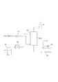
- FIG. 1 shows an exhaust gas treatment facility using a flue gas desulfurization apparatus according to the present invention.
- Sulfur was removed by an exhaust gas fan 51 that supplies combustion exhaust gas discharged from a thermal power plant or the like, a seawater method flue gas desulfurization device 50 that processes the exhaust gas supplied from the exhaust gas fan 51, and a seawater method flue gas desulfurization device 50
- a chimney 52 that discharges gas, a seawater supply pump 53 that supplies seawater to the seawater method smoke treatment apparatus 50, a screen 54 that removes marine organisms in the seawater, and a seawater supply pipe 55 are included. Marine life is contained in the seawater supplied by the seawater supply pump 53.
- seawater in the lower part of the seawater method flue gas desulfurization apparatus 50 is mixed with seawater 57 supplied separately in the wastewater treatment facility 56, and then subjected to aeration processing by an aeration blower 58 and discharged into marine seawater.
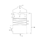
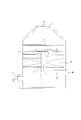
- FIG. 2 is an elevation (cross-sectional) view of the first embodiment of the flue gas desulfurization apparatus according to the present invention applied as, for example, the seawater method flue gas treatment apparatus 50 of FIG.
- a supply port 2 for supplying exhaust gas (for example, combustion exhaust gas from a waste heat boiler in a power generation facility) G is provided on the lower side surface of the gas-liquid contact tower 1 as a basic component of the flue gas desulfurization apparatus. Further, on the upper surface of the gas-liquid contact tower 1, an exhaust port 6 for exhausting the treated exhaust gas TG that has undergone the treatment in the gas-liquid contact tower 1 is provided.
- exhaust gas for example, combustion exhaust gas from a waste heat boiler in a power generation facility
- a supply pipe 3 for introducing fresh seawater SW as a contact liquid into the gas-liquid contact tower 1 and the fresh seawater supplied to the supply pipe 3 are connected.
- a number of nozzles 4 for injecting SW downward in the gas-liquid contact tower 1 are provided.
- “fresh seawater” SW is seawater led from the sea, and sulfur oxidation after absorption treatment performed on a perforated plate 5 in the gas-liquid contact tower 1 described later.
- the fresh seawater can use the used cooling water which comes out of the condenser (condenser) of a boiler installation, and the brine which comes out of a seawater desalination installation other than what was directly taken in from the sea as mentioned above.
- the supply pipe 3 and the nozzle 4 constitute seawater dispersion supply means of the present invention.
- the shape of the outlet of the supply nozzle 4 is not limited to a round shape, a square shape, or a polygonal shape, but a round shape is preferable.
- the diameter of the supply nozzle 4 is preferably 50 to 150 mm, particularly 65 to 125 mm.
- the diameter of the supply nozzle 4 indicates the maximum length of the opening when the shape is a square or a polygon.
- the fresh seawater SW may contain solids such as shellfish and seaweed, which causes the nozzle to be blocked. Therefore, by setting the diameter of the nozzle 4 to 50 mm or more, shellfish can be passed, and seawater can be jetted while preventing the nozzle from being blocked.
- the diameter of the supply pipe 3 is also desirably 50 mm or more.
- a perforated plate for example, a moletana
- the perforated plate is formed with openings 5a in a range of 3000 / m 2 to 7800 / m 2 .
- the opening shape of the perforated plate is not limited to a round shape, a square shape, or a polygonal shape, but a round shape is preferable.
- the aperture diameter of the perforated plate is preferably 5 to 20 mm, particularly 8 to 12 mm. The opening diameter indicates the maximum length of the opening when the shape is a square or a polygon.
- the thickness By setting the thickness to 5 to 20 mm, impurities such as shellfish contained in fresh seawater sprayed from the seawater dispersion supply means easily fall onto the regular packing from the opening of the perforated plate, while the perforated plate 5 Therefore, it is possible to prevent the liquid from staying for a long time.
- the opening diameter on the porous plate smaller than the nozzle diameter of the seawater dispersion supply means, it becomes possible to collect impurities (particularly shellfish) contained in the seawater on the porous plate. The collected contaminants can be removed when the operation is stopped.
- the exhaust gas G supplied from the supply port 2 installed on the lower side surface of the gas-liquid contact tower 1 is directed upward in the gas-liquid contact tower 1 through the flow path of the regular packing 20 and the opening of the porous plate 5 in order.
- fresh seawater SW is supplied to the supply nozzle 4 through the supply pipe 3.
- the supply pipe 3 is also connected to a pipe for supplying a part of the seawater that has absorbed sulfur oxides stored below the gas-liquid contact tower 1, and the seawater can be circulated and used in accordance with the operation. .
- Fresh seawater SW sprayed downward from the supply nozzle 4 provided in the upper part of the gas-liquid contact tower 1 is formed of the exhaust gas G, the porous plate 5 provided in the middle part of the gas-liquid contact tower 1 and the regular packing 20.
- Counter-current contact is made in the upper end and in the flow path. Through the countercurrent contact, the sulfur oxide contained in the exhaust gas is absorbed by the fresh seawater SW and removed from the exhaust gas. The sulfur oxide that has absorbed the sulfur content in the exhaust gas is sent from the discharge port provided below the gas-liquid contact tower 1 to the wastewater treatment facility via the flow path.
- the ratio (L / G) of the flow rate G (kg / m 2 ⁇ hr) of the exhaust gas G to the flow rate L (kg / m 2 ⁇ hr) of the fresh seawater SW is 3 or more, preferably 4 to 15 is there.
- the treated exhaust gas TG from which the sulfur oxide has been removed is exhausted from an exhaust port 6 provided in the upper part of the gas-liquid contact tower 1. Further, the seawater that has absorbed the sulfur oxide falls downward in the gas-liquid contact tower 1.
- a regular packing 20 having a substantially uniform flow path with respect to the cross section is provided in a tower facing the vertical direction, and a gas to be treated (for example, exhaust gas G) is blown into the tower below the tower.
- the seawater dispersion supply means 3 and 4 for supplying the liquid in a state of being distributed with respect to the upper surface of the porous plate 5 above the porous plate 5 by providing the porous plate 5 having substantially uniform openings above the regular packing 20.
- the gas to be processed that blows up in the tower and the descending seawater are brought into gas-liquid contact to process the gas to be processed.
- the seawater supplied from the seawater dispersion supply means 3, 4 passes through the openings 5 a, 5 a... While diffusing in the surface direction on the porous plate 5, and each flow path 20 a of the regular packing 20. , 20a... Therefore, the dispersibility of the seawater is improved as compared with the case where the seawater is directly flowed down from the seawater dispersion supply means 3 and 4 to the respective flow paths 20a, 20a,.
- the gas-liquid contact efficiency is high.
- the gas-liquid contact on the perforated plate 5 not only the gas-liquid contact on the perforated plate 5 but also the seawater supplied from the seawater dispersion supply means 3, 4 is caused to flow down to the flow paths 20 a, 20 a.
- a gas-liquid contact is intended. Therefore, since the gas-liquid contact is made even in the process of passing through the respective flow paths 20a, 20a... Having long passages in the height direction of the regular packing 20, the gas-liquid contact time becomes long. High efficiency.
- the seawater supplied from the seawater dispersion supply means 3, 4 is caused to flow down to the flow paths 20 a, 20 a. There is a risk of creating a flow path 20a that does not pass.
- the cost of the seawater dispersion supply means 3 and 4 becomes high.
- the seawater supply position is set in advance in a state of diffusing in the surface direction on the perforated plate 5, thereby dispersing the regular filler 20. Supply is possible, and it is configured to smoothly pass through each of the flow paths 20a, 20a. As a result, even if the number of nozzles 4 is reduced, sufficient diffusibility of seawater is ensured.
- the configuration of the present invention that is, a regular packing, a perforated plate having openings, and a seawater dispersion supply means for supplying seawater are provided in the example of FIG. 2.
- a plurality of stages can be provided at intervals.
- the example of FIG. 4 shows an example in which a seawater dispersion supply means for supplying regular packing and seawater is provided, and further, a regular packing, a perforated plate having openings, and a seawater dispersion supply means for supplying seawater are provided thereabove. It was.
- FIG. 4 shows an example in which a seawater dispersion supply means for supplying regular packing and seawater is provided, and further, a regular packing, a perforated plate having openings, and a seawater dispersion supply means for supplying seawater are provided thereabove.
- the perforated hole having an opening in the lower stage is intentionally provided. There is no need to install additional plates, and there is also a meaning to prevent pressure loss.
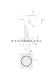
- FIG. 9 is a plan view of seawater dispersion supply means.
- the seawater dispersion supply means of this structure is provided with a supply pipe 3 for carrying seawater supplied from the outside, and a number of downward supply nozzles 4 communicating with this.
- the supply pipe 3 communicates with the supply liquid supply nozzle X on the lower side surface of the absorption tower body, extends horizontally toward the center of the flat section of the absorption tower body, and extends upward from the vicinity of the center.
- stretching above the regular packing filled in the absorption tower it branches in a horizontal direction and the downward supply nozzle 4 is provided in each branched piping.
- the supply nozzles are preferably arranged in a distributed manner at a rate of 1 / m 2 to 100 / m 2 , more preferably 2 / m 2 to 6 / m 2 . If the number of supply nozzles is excessively increased, the weight of the seawater dispersion supply means will increase. In particular, since the seawater dispersion supply means is installed above the absorption tower, the center of gravity of the entire absorption tower is increased, and a large-sized foundation is required. Further, as another example of the seawater dispersion supply means, as shown in FIG. 10, it includes an upper opening pipe line and an outflow weir opening formed on the side wall thereof, and the weir opening is 2 / m 2 to 50 / It may have a structure in which it is distributed at a ratio of m 2 .
- the exhaust gas G supplied from the supply port 2 installed on the lower side surface of the gas-liquid contact tower 1 is directed upward in the gas-liquid contact tower 1, opening of the porous support member 21 (see FIG. 8), regular packing
- the 20 flow paths and the opening of the porous plate 5 are moved in order.
- fresh seawater SW sprayed downward from the supply nozzle 4 provided in the upper part of the gas-liquid contact tower 1 is exhaust gas G, on the perforated plate 5 provided in the middle part of the gas-liquid contact tower 1 and regularly packed.
- Countercurrent contact is made in the upper end of 20 and in the flow path. Through the countercurrent contact, the sulfur oxide contained in the exhaust gas is absorbed by the fresh seawater SW and removed from the exhaust gas.
- an eliminator 22 for removing mist in the treated exhaust gas G is preferably provided above the nozzle 4.
- the superficial velocity of the gas to be treated that blows up inside the tower 1 should be 2.0 m / sec to 3.2 m / sec in relation to the required gas throughput and equipment size. desirable.
- This factor creates new problems. That is, at first, the present inventors finally distribute the seawater discharged from the seawater dispersion supply means 3 and 4 on the perforated plate 5, so that the nozzle may be discharged upward. I thought.
- the superficial velocity of the rising gas is high, if even a slight gas drift occurs in the cross section above the perforated plate, the seawater will be affected by the gas drift and drift down with respect to the cross section.
- the flow rate of seawater immediately above the regular packing 20 is 2.0 m / second or more, particularly 2.5 m / second or more.
- the depth of the liquid layer at this time is 5 mm to 200 mm in a state where the exhaust gas G is not supplied. Further, the liquid layer is fluidized violently due to the rise of the exhaust gas. Furthermore, the clogging of the opening 5a of the perforated plate 5 is prevented while fluidizing impurities such as shellfish.
- the position of the liquid flow flowing down from the seawater dispersion supply nozzle 4 with respect to the upper surface of the porous plate 5 substantially coincides with the position of the opening 5a of the porous plate 5 in the vertical direction, the kinetic energy of the flowing-down liquid is There is a clear advantage over the rising gas energy.
- the minimum passage diameter of the flow path in the height direction of the regular packing 20 is preferably 10 to 30 mm.
- a part of the foreign substance floating on the perforated plate 5 is preferably dropped through the opening 5a, passes through the regular packing 20, and flows down from the lower end. Therefore, it is preferable that the minimum passage diameter of the oblique flow passage 20A, the flow passage 20B, and the flow passage 20C of the regular packing 20 described below is 10 to 30 mm.
- This minimum passage diameter of 10-30 mm is greatly related to the opening diameter of the perforated plate being 5-20 mm ⁇ , but since most of the foreign substances are floating and staying on the perforated plate 5, it happens to be the opening of the perforated plate. It is set as a diameter that allows the contaminants that have passed through to flow smoothly.
- the seawater dispersion supply means includes a supply pipe 3 and a number of downward supply nozzles 4 communicating with the supply pipe 3, and the supply nozzles are dispersedly arranged at a rate of 2 / m 2 to 50 / m 2 as an example. Can be mentioned.
- the supply nozzle diameter of the seawater dispersion supply means is 50 mm to 150 mm, more preferably 65 mm to 125 mm.
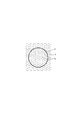
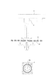
- FIG. 11 shows an example of the size of the supply nozzle 4 aperture and the aperture 5a of the perforated plate 5 and the positional relationship of the aperture 5a of the perforated plate 5 on the flow-down projection area with respect to one supply nozzle 4 aperture.
- a positional relationship in which 6 to 135 apertures of the perforated plate are included in the projected projection area of one supply nozzle 4 is preferable, and a positional relationship in which 13 to 63 apertures are included is particularly preferable.
- FIG. 11 shows about 13 examples. Since a plurality of apertures of the perforated plate are included in the flow-down projected area of one supply nozzle 4, even if one of the openings 5a of the perforated plate 5 located below the supply nozzle 4 is closed, the remaining aperture 5a Since at least one of these will show the peak of a flow-down speed, seawater can be reliably supplied to the regular packing 20.
- the seawater dispersion and supply means includes an upper opening conduit 40 and an outflow weir opening 40B formed in the side wall 40A, and the weir opening 40B is 2 / m 2 to 50 / m. It may be a form that is distributed at a ratio of 2 .
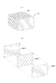
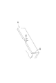
- the regular packing 20 shown in FIG. 7 can be used.
- a large number of corrugated sheets A and B having different wave crest directions of 90 degrees are used.
- the crossing angle may be another angle (for example, 45 or 60 degrees), or a channel whose channel is not inclined can be used.
- the regular packing 20 is spread in the tower 1, and this spread can be performed in one stage or in appropriate plural stages.
- the directionality can be changed for each single regular packing 20 so that the flow path direction becomes more random.
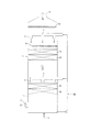
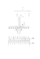
- FIGS. 12 and 13 in the middle of the regular packing 20 in the height direction, there are a large number of oblique flow passages 20A for gas blown from below, and at least at the upper end portion, the oblique flow passages. It can be set as the form which has the flow path 20B which raises the diagonally ascending gas which passes through 20A to the soot direction.
- a flow path 20 ⁇ / b> C that guides upward in the heel direction can also be provided at the lower end portion.
- the number of openings 5a immediately below the supply nozzle 4 is reduced as shown in FIG.
- a technique such as reducing the diameter of the opening 5a immediately below the supply nozzle 4 in FIG. 16 can be appropriately employed to determine the flow mode of the flow-down liquid into the regular packing.
- FIG. 17 shows a ship desulfurization apparatus as another installation example of the flue gas desulfurization gas-liquid contact tower.
- the exhaust gas discharged from the ship engine 61 mounted on the ship 60 is processed using the flue gas desulfurization tower 50 of the present invention.
- a marine engine that drives the marine vessel 1
- a seawater flue gas desulfurization tower 50 that processes exhaust gas from the marine engine 61
- a water absorption pump 62 that supplies seawater to the seawater flue gas desulfurization tower 50A
- marine organisms in the seawater A screen 63 for removing the exhaust gas, an exhaust gas fan 68 for discharging the exhaust gas treated in the flue gas desulfurization tower 50 to the atmosphere, a chimney 64, a seawater storage tank 65 for storing seawater that has absorbed sulfur oxides in the seawater flue gas desulfurization tower 50,
- a wastewater treatment device 66 for removing impurities therein and an outflow pipe 67 are provided.
- the seawater flue gas processing tower has the same structure as the first embodiment.
- sulfur oxides in the combustion exhaust gas are absorbed into the seawater.
- Seawater that has absorbed sulfur oxides is discharged into the sea through the discharge pipe 67.
- the seawater method flue gas desulfurization apparatus disclosed in the present invention is not only a desulfurization process that absorbs sulfur in exhaust gas, but also equipment that absorbs hydrogen chloride into water and recovers hydrochloric acid, and nitrogen oxides in exhaust gas into seawater. It can be applied to a known absorption process such as a facility for absorbing and removing. Further, it can be applied to a diffusion process in which organic substances in wastewater are diffused into gas by air or steam.
Abstract
Description
多孔板上または充填物表面で海水と効率よく接触させることは、排ガスの処理効率(脱硫効率)を高めるためにきわめて重要なことである。
実際、本発明者らは、長期間運転した排煙脱硫設備のモレタナ上には、死後離脱した貝の欠片の大きな堆積物すら観察されることに、大いに驚いた次第である。
他の課題は、充填物の流路全体に海水を分散供給できるようにすることにより、被処理ガスの高い処理効率を確保することにある。
さらに、海水法特有の課題として、海生生物の装置内への侵入に伴う、接触効率の低下を防止することにある。
前記規則充填物上方に実質的に均等配置の多数の開口を有する多孔板を設け、その多孔板の上方に多孔板上面に対し海水を分散供給する海水分散供給手段を設け、
吹き上がる被処理ガスと、下降する海水とを気液接触させ、被処理ガスを処理するようにしたことを特徴とする排煙脱硫装置である。
他方、海水分散供給手段は、供給管とこれに連通する多数の下向きの供給ノズルを含み、供給ノズルは2個/m2~4個/m2の割合で均等分散配置されている構造のものを使用できる。
また、海水分散供給手段の供給ノズル径は50~150mm、特に65~125mmであるのが好ましく、ノズルの断面積は0.002~0.018m2/個が望ましい。さらに、供給ノズル1個からの流下投影面積中に多孔板の開口が6個~135個、特に13~65個有することが好ましい。
吹き上がる前記ガスと、下降する海水とを気液接触させ、被処理ガスを処理することを特徴とする排煙脱硫方法を提供する。
これに対向する、多孔板の開口径は、5~20mmφ、特に8~12mmφであるのが好ましく、かつ、開口率は25~60%、特に30~40%であるのが望ましい。
多孔板の開口数は、3000個/m2~7800個/m2であるのが望ましい。
前記規則充填物の高さ方向流通路の最小通過径が10~30mmであるのが望ましい。
しかし、貝類には、幼生など小さいもの、あるいは配管中で割れるなどして微小化したものもある。そこで、多孔板の開口を通った小径分は、規則充填物の流通路を通して落下させるようにする。
さらに多孔板上で捕捉された貝類は、多孔板上に形成された海水による液層中で下方から吹き上がるガスによってバブリングされ、貝類が多孔板の開口を塞がない、あるいは詰まることがない遊動状態にすることが重要であることを知見したのである。
また、海生生物の装置内への侵入に伴う、接触効率の低下を防止することができ、接触効率の向上と長時間の安定した運転の両者を達成できる。
火力発電所等から排出された燃焼排ガスを供給する排ガスファン51と、排ガスファン51から供給された排ガスを処理する海水法排煙脱硫装置50、海水法排煙脱硫装置50で硫黄を除去されたガスを排出する煙突52、海水法排煙処理装置50に海水を供給する海水供給ポンプ53、海水中の海生生物を除去するスクリーン54、および海水供給配管55からなる。海水供給ポンプ53により供給される海水中に海生生物が含まれている。これらの海生生物のうち、スクリーン54で除去しきれない小さな幼生などが海水供給配管55中に付着し成長する。
海水法排煙脱硫装置50下部の海水は、排水処理設備56において別途供給される海水57と混合されたのち、曝気ブロワ58による曝気処理を受け、海洋の海水中に排水されるものである。
なお、本実施例において「新鮮な海水」SWとは、代表例は海から導いた海水のことであり、後述する気液接触塔1内の多孔板5上で行われる吸収処理後の硫黄酸化物を含む海水と区別される。新鮮な海水は、前記のように海から直接取水したもの以外にも、ボイラー設備の復水器(コンデンサ)から出る使用済み冷却水や、海水脱塩設備から出るブラインを使用可能である。
多孔板には、開口5aが3000個/m2~7800個/m2 の範囲で形成される。
多孔板の開口形状は、丸形、角形、多角形など限定されないが、丸形が好ましい。多孔板の開口口径は、5~20mm、特に8~12mmであるのが好ましい。開口口径は、形状が、角形、多角形の場合、開口の最大長さを指す。5~20mmとすることで、海水分散供給手段から噴射された新鮮な海水中に含まれる貝などの夾雑物が多孔板の開口から規則充填物上に、安易に落下し、他方で多孔板5で長期に滞留することを防止することができる。このように海水分散供給手段のノズル口径より多孔板上の開口口径を小さくすることで、海水中に含まれる夾雑物(特に貝類)を多孔板上で捕集することが可能となる。なお、捕集した夾雑物は、運転停止時に除去することができる。
他方、気液接触装置として、規則充填物を設け、その上方から海水を噴霧するものも知られている。
本発明においては、両者を併用するもので、多孔板5の下方に、規則充填物20を設けるものである。21は、規則充填物20の底面を支持する多孔支持部材である。規則充填物は、一段に限定されず、複数段とするのが接触効率を高めるために望ましい。
他方、新鮮な海水SWが、供給管3を通じて供給ノズル4に供給される。なお、供給管3は、気液接触塔1の下方に貯留された硫黄酸化物を吸収した海水の一部を供給する配管とも連結されており、運転に応じて海水を循環使用することができる。気液接触塔1上部に設けられた供給ノズル4から下方へ噴射された新鮮な海水SWは、排ガスGと、気液接触塔1内中部に設けられた多孔板5上及び規則充填物20の上端及び流路内で向流接触する。当該向流接触によって、排ガス中に含まれる硫黄酸化物は新鮮な海水SWに吸収され、排ガス中から除去される。排ガス中の硫黄分を吸収した硫黄酸化物は、気液接触塔1の下方に設けられた排出口から流路を介して排水処理設備に送られる。
このとき、排ガスGの流量G(kg/m2 ・hr)と新鮮な海水SWの流量L(kg/m2 ・hr)の比(L/G)は、3以上、好ましくは4~15である。
硫黄酸化物が除去された処理排ガスTGは、気液接触塔1上部に設けられた排気口6から排気される。また、硫黄酸化物を吸収した海水は、気液接触塔1内下方へ降下する。
したがって、規則充填物20の高さ方向に長い通路をもった各流路20a,20a…を通り抜ける過程でも気液接触するので、気液接触の時間が長いものとなり、この観点からも気液接触効率が高いものとなる。
一方、ノズル4を多数配置するとなると、海水分散供給手段3,4のコストが高いものとなる。しかしながら、本発明では、各供給ノズル4から海水を供給する際に、予め海水の供給位置を多孔板5上で面方向に拡散した状態に位置設定しておくことにより、規則充填物20に分散供給が可能であり、その各流路20a,20a…を円滑に下方に通り抜けるようにしてある。その結果、ノズル4の配設個数を少なくしたとしても、十分な海水の拡散性が確保される。
図4の例は、規則充填物及び海水を供給する海水分散供給手段を設け、さらに、その上方に規則充填物、開口を有する多孔板及び海水を供給する海水分散供給手段を設けた例を示した。図4の例では、上段での海水を供給する海水分散供給手段及び多孔板によって、上段の規則充填物には均一に海水が流下するようになっているので、あえて、下段に開口を有する多孔板を追加設置する必要がなく、かつ、圧力損失の防止を図る意味もある。
実験装置:吸収塔寸法1500mm×1500mmで高さ3000mm
充填物:樹脂製規則充填物(300mm高さ/モジュール)
充填高さ:1段積み
供給ガス流量:24,000m3/H
供給ガス成分:空気
供給液流量:144m3/H
<実験1>:規則充填物上方に多孔板なし(図3の構成)
<実験2>:規則充填物上方に多孔板あり(図2の構成)
本実験結果に基づいて所定の気液接触効率を得るために必要なノズル個数を算出した。
算出結果によると実験1の場合には、ノズルを約20個/m2配置する必要があったものに対し、実験2の場合には、ノズルは約4個/m2の配置で足りることを知見した。
また、海水分散供給手段の他の例として、図10に示すように、上方開口管路と、その側壁に形成された流出堰開口を含み、前記堰開口は2個/m2~50個/m2の割合で分散配置されている構造のものでもよい。
他方、気液接触塔1上部に設けられた供給ノズル4から下方へ噴射された新鮮な海水SWは、排ガスGと、気液接触塔1内中部に設けられた多孔板5上及び規則充填物20の上端及び流路内で向流接触する。当該向流接触によって、排ガス中に含まれる硫黄酸化物は新鮮な海水SWに吸収され、排ガス中から除去される。図8に示すように、好適にはノズル4の上方には、処理された排ガスG中のミストを除去するエリミネ-タ22が設けられている。
この要因によって、新たな問題を生じる。すなわち、当初、本発明者らは、海水分散供給手段3,4から流出させた海水は最終的に多孔板5上で分散するので、ノズルの向きは上向きに流出させるようにしてもよいのではないかと考えた。
しかし、上昇するガスの空塔速度が速いので、多孔板上方の横断面において、少しでもガスの偏流が生じていると、海水がガスの偏流に影響されて横断面に関し偏って流下するようになることが知見された。
よって、海水は、供給ノズルを下向きに設置し、供給することが望ましい。海水法排煙脱硫装置として適用する場合、規則充填物20直上での海水の流下速度は2.0m/秒以上、特に2.5m/秒以上にするのが望ましい。
海水分散供給ノズル4から流下する海水は、多孔板5上で跳ね返ったりしながら、面方向に拡散する。通常、排ガスGの流量G(kg/m2 ・hr)と新鮮な海水SWの流量L(kg/m2 ・hr)の比(L/G)は、4~15であることから
海水多孔板5上で液層を形成する。このときの液層の深さは、排ガスGの供給が無い状態で5mm~200mmである。また、液層は、排ガスガスの上昇によって激しく流動化する。さらに、貝類などの夾雑物を流動化させながら、多孔板5の開口5aの閉塞防止する。
しかるに、多孔板5上面に対して海水分散供給ノズル4から流下する液流の位置が、多孔板5の開口5a位置と鉛直方向に実質的に一致していると、その流下液の運動エネルギーが上昇するガスエネルギーに対して明確に優勢となる。
その結果、図6に示す流下速度分布のように、多孔板5の開口5a中心と鉛直方向に実質的に一致している位置において、ピークを示す。
そして、流下速度分布がある横断面において、多数のピークを示すと、そのピーク位置においては、流下液の運動エネルギーが、上昇ガス流れに対して遙かに優勢なのであるから、あたかも、当該開口5aから液の流下が始まるような形態となり、規則充填物20の流路20a内に確実に液が流入するようになる。しかも、多孔板5から各開口5a位置のみでなく、分散して状態で液が流下するから、規則充填物20の各流路20a内に分散して流下するようになり、きわめて好適な形態となる。
図11に供給ノズル4口径と多孔板5の開口5aとの大きさ、および供給ノズル4口径1個に対する流下投影面積上の多孔板5の開口5aの位置関係例を図示した。
1つの供給ノズル4の流下投影面積中に多孔板の開口が6個~135個が含まれる位置関係が好ましく、特に13~63個が含まれる位置関係がより好ましい。図11には約13個の例で示されている。1つの供給ノズル4の流下投影面積中において多孔板の開口が複数含むよう配置されているため、供給ノズル4の下に位置する多孔板5の開孔5aの一つが閉塞したとしても残る開口5aの少なくとも1つは、流下速度のピークを示すこととなるため、確実に規則充填物20へ海水を供給することができる。
かかる適宜の容積サイズとして規則充填物20は、塔1内に敷き詰め、この敷き詰めは1段又は適宜の複数段をもって行なうことができる。規則充填物20の敷き詰めに際しては、流路方向がよりランダムになるように、単一の規則充填物20ごとに方向性を変更することができる。
規則充填物としては、挙示の例に限定されず、市販の又は公知の種々の規則充填物を使用できる。
硫黄酸化物を吸収した海水は、排出管路67と通じて海へ放出される。
2・・・供給口
3・・・供給管
4・・・ノズル
5・・・多孔板(モレタナ)
5a・・・開口
6・・・排気口
7・・・海水貯留部
8・・・堰
9・・・海水誘導部
10・・・海水路
13・・・排出口
20・・・規則充填物(構造充填物)
G・・・排ガス
TG・・・処理排ガス
SW・・・新鮮な海水
Claims (14)
- 竪向きの塔内に、横断面に関し実質的に均等な流通路を有する規則充填物を設け、これより下方において塔内にガスを吹込み、塔内を吹き上がるようになし、
前記規則充填物上方に実質的に均等配置の多数の開口を有する多孔板を設け、その多孔板の上方に多孔板上面に対し海水を分散供給する海水分散供給手段を設け、
吹き上がる被処理ガスと、下降する海水とを気液接触させ、被処理ガスを処理するようにしたことを特徴とする排煙脱硫装置。 - 海水分散供給手段は、海水を多孔板に供給する複数の開口を有し、前記開口の少なくとも一部は、当該開口中心が前記多孔板の開口と鉛直方向に一致している請求項1記載の排煙脱硫装置。
- 海水分散供給手段は、供給管とこれに連通する複数の下向きの供給ノズルを含み、前記供給ノズルは2個/m2~50個/m2の割合で分散配置されている請求項1又は2記載の排煙脱硫装置。
- 海水分散供給手段は、供給管とこれに連通する複数の下向きの供給ノズルを含み、前記供給ノズルは、口径が50~150mmであり、供給ノズル1個からの流下投影面積中に多孔板の開口が6個~135個含まれる位置に設けられた請求項1又は2記載の排煙脱硫装置。
- 前記海水供給手段は供給管と、供給管と連通する、口径が50~150mmである複数の供給ノズルを備え、かつ、前記多孔板の開口径は、5~20mmであることを特徴とする請求項1記載の海水法排煙脱硫装置
- 竪向きの塔内に、横断面に関し実質的に均等な流通路を有する規則充填物を設け、これより下方において塔内にガスを吹込み、塔内を吹き上がるようになし、
前記規則充填物上方に実質的に均等配置の多数の開口を有する多孔板を設け、その多孔板の上方に多孔板上面に対し海水を分散供給する海水分散供給手段を設け、
多孔板上には、海水により液層が形成され、前記規則充填物では
吹き上がる前記ガスと、下降する海水とを接触させ、被処理ガスを処理することを特徴とする排煙脱硫方法。 - 海水分散供給手段は、海水を多孔板に供給する多数の開口を有し、前記開口の少なくとも一部は、当該開口中心が前記多孔板の開口と鉛直方向に一致している請求項6記載の排煙脱硫方法。
- 多孔板の開口径は、5~20mmであり、かつ、開口率は25~60%である請求項6又は7記載の排煙脱硫方法。
- 多孔板の開口数は、3000個/m2~7800個/m2である請求項6記載の排煙脱硫方法。
- 海水分散供給手段は、供給管とこれに連通する多数の下向き供給ノズルを含み、供給ノズルは2個/m2~50個/m2の割合で分散配置されている請求項6記載の排煙脱硫方法。
- 海水分散供給手段は、供給管とこれに連通する多数の下向き供給ノズルを含み、その供給ノズルは口径が50~150mmであり、供給ノズル1個からの流下投影面積中に多孔板の開口が6個~135個含まれる位置に設置され、供給ノズル先端の流速が2.0~3.0m/秒である請求項6記載の排煙脱硫方法。
- 塔内に吹込まれ吹き上がる前記ガスの空塔速度を2.0m/秒~3.2m/秒とし、前記規則充填物直上での海水の流下速度が2.0m/秒以上である請求項6記載の排煙脱硫方法。
- 前記規則充填物の高さ方向中間には、下方から吹き込まれるガスの斜め流通路を多数有し、かつ、少なくとも上端部に、前記斜め流通路を通る斜め上昇ガスを竪向きに上昇させる流通路を有する請求項6記載の排煙脱硫方法。
- 前記規則充填物の高さ方向流通路の最小通過径が10~30mmである請求項6記載の排煙脱硫方法。
Priority Applications (2)
| Application Number | Priority Date | Filing Date | Title |
|---|---|---|---|
| MYPI2015700270A MY188935A (en) | 2012-07-31 | 2013-07-31 | Flue gas desulfurization apparatus and flue gas desulfurization method |
| PH12015500171A PH12015500171B1 (en) | 2012-07-31 | 2015-01-26 | Flue gas desulfurization apparatus and flue gas desulfurization method |
Applications Claiming Priority (4)
| Application Number | Priority Date | Filing Date | Title |
|---|---|---|---|
| JP2012169803 | 2012-07-31 | ||
| JP2012-169803 | 2012-07-31 | ||
| JP2013158510A JP6142432B2 (ja) | 2012-07-31 | 2013-07-31 | 排煙脱硫方法および排煙脱硫装置 |
| JP2013-158510 | 2013-07-31 |
Publications (1)
| Publication Number | Publication Date |
|---|---|
| WO2014021380A1 true WO2014021380A1 (ja) | 2014-02-06 |
Family
ID=50028050
Family Applications (1)
| Application Number | Title | Priority Date | Filing Date |
|---|---|---|---|
| PCT/JP2013/070742 WO2014021380A1 (ja) | 2012-07-31 | 2013-07-31 | 排煙脱硫装置および排煙脱硫方法 |
Country Status (4)
| Country | Link |
|---|---|
| JP (1) | JP6142432B2 (ja) |
| MY (1) | MY188935A (ja) |
| PH (1) | PH12015500171B1 (ja) |
| WO (1) | WO2014021380A1 (ja) |
Cited By (1)
| Publication number | Priority date | Publication date | Assignee | Title |
|---|---|---|---|---|
| CN113797659A (zh) * | 2021-10-25 | 2021-12-17 | 莱芜钢铁集团泰东实业有限公司 | 一种具有热能转化利用的高炉烟气净化装置 |
Families Citing this family (1)
| Publication number | Priority date | Publication date | Assignee | Title |
|---|---|---|---|---|
| JP2020168596A (ja) * | 2019-04-02 | 2020-10-15 | 三菱日立パワーシステムズ株式会社 | 海水脱硫装置 |
Citations (5)
| Publication number | Priority date | Publication date | Assignee | Title |
|---|---|---|---|---|
| JPS494669A (ja) * | 1972-05-08 | 1974-01-16 | ||
| JPH041391U (ja) * | 1990-04-18 | 1992-01-08 | ||
| JP2001129352A (ja) * | 1999-11-02 | 2001-05-15 | Fujikasui Engineering Co Ltd | 海水による排ガス脱硫高度処理プロセス |
| JP2008200619A (ja) * | 2007-02-21 | 2008-09-04 | Mitsubishi Heavy Ind Ltd | 排煙脱硫装置 |
| JP2011523993A (ja) * | 2008-06-13 | 2011-08-25 | 斯幹 彭 | 航海船における排ガス洗浄装置および排ガス洗浄方法 |
Family Cites Families (5)
| Publication number | Priority date | Publication date | Assignee | Title |
|---|---|---|---|---|
| JPH09155142A (ja) * | 1995-12-07 | 1997-06-17 | Idemitsu Eng Co Ltd | 気液接触による特定成分除去方法並びに除去装置及び該装置に用いるトレイ |
| JPH11290643A (ja) * | 1998-04-13 | 1999-10-26 | Fuji Kasui Eng Co Ltd | 海水による排ガス中の酸性成分の除去方法 |
| JP4145701B2 (ja) * | 2003-04-07 | 2008-09-03 | 清水建設株式会社 | 空気浄化装置 |
| JP2007098307A (ja) * | 2005-10-05 | 2007-04-19 | Fujikasui Engineering Co Ltd | 循環型炭酸ガス固定化システム |
| JP4604014B2 (ja) * | 2006-11-20 | 2010-12-22 | 株式会社清流メンテナンス | 生物脱臭システム及びこのシステムに用いられる生物脱臭装置 |
-
2013
- 2013-07-31 MY MYPI2015700270A patent/MY188935A/en unknown
- 2013-07-31 JP JP2013158510A patent/JP6142432B2/ja active Active
- 2013-07-31 WO PCT/JP2013/070742 patent/WO2014021380A1/ja active Application Filing
-
2015
- 2015-01-26 PH PH12015500171A patent/PH12015500171B1/en unknown
Patent Citations (5)
| Publication number | Priority date | Publication date | Assignee | Title |
|---|---|---|---|---|
| JPS494669A (ja) * | 1972-05-08 | 1974-01-16 | ||
| JPH041391U (ja) * | 1990-04-18 | 1992-01-08 | ||
| JP2001129352A (ja) * | 1999-11-02 | 2001-05-15 | Fujikasui Engineering Co Ltd | 海水による排ガス脱硫高度処理プロセス |
| JP2008200619A (ja) * | 2007-02-21 | 2008-09-04 | Mitsubishi Heavy Ind Ltd | 排煙脱硫装置 |
| JP2011523993A (ja) * | 2008-06-13 | 2011-08-25 | 斯幹 彭 | 航海船における排ガス洗浄装置および排ガス洗浄方法 |
Cited By (2)
| Publication number | Priority date | Publication date | Assignee | Title |
|---|---|---|---|---|
| CN113797659A (zh) * | 2021-10-25 | 2021-12-17 | 莱芜钢铁集团泰东实业有限公司 | 一种具有热能转化利用的高炉烟气净化装置 |
| CN113797659B (zh) * | 2021-10-25 | 2022-10-11 | 莱芜钢铁集团泰东实业有限公司 | 一种具有热能转化利用的高炉烟气净化装置 |
Also Published As
| Publication number | Publication date |
|---|---|
| PH12015500171A1 (en) | 2015-03-16 |
| JP6142432B2 (ja) | 2017-06-07 |
| JP2014042909A (ja) | 2014-03-13 |
| MY188935A (en) | 2022-01-13 |
| PH12015500171B1 (en) | 2015-03-16 |
Similar Documents
| Publication | Publication Date | Title |
|---|---|---|
| KR101698999B1 (ko) | 선박 연도 가스 세척 장치 및 방법 | |
| JP5631985B2 (ja) | 改良されたガス洗浄装置および方法 | |
| KR101431077B1 (ko) | 선박용 배기가스 탈황을 위한 멀티 스크러버 장치 | |
| WO2014156985A1 (ja) | 海水排煙脱硫装置とその運用方法 | |
| KR102475344B1 (ko) | 듀얼 워터 시스템을 가진 인라인 스크러버 | |
| JP2020519806A (ja) | 拡散手段を有する排気ガス処理装置 | |
| EP3834913B1 (en) | Multi-level gas scrubber with multiple flooded scrubber heads | |
| JP5177859B2 (ja) | 脱硫脱炭装置 | |
| KR20150070110A (ko) | 연도 가스 정화장치 | |
| KR101431081B1 (ko) | 선박용 배기가스 탈황을 위한 고효율 멀티 스크러버 장치 | |
| WO2015030352A1 (ko) | 선박용 배기가스 탈황 장치 | |
| KR101981066B1 (ko) | 부식 방지 기능을 가진 배기가스 처리 시스템 | |
| JP6142432B2 (ja) | 排煙脱硫方法および排煙脱硫装置 | |
| US20090151563A1 (en) | Extraction device | |
| JP2014042909A5 (ja) | ||
| CN111437694A (zh) | 一种船用烟气脱硫设备 | |
| WO2022083613A1 (zh) | 一种卧式气体处理装置 | |
| WO2012105905A1 (en) | Apparatus and method for removing or reducing of gas pollutants from exhaust gas stream | |
| JP2006122862A (ja) | 排ガス処理装置 | |
| KR102038944B1 (ko) | 향상된 공간활용도를 가진 하이브리드형 배기가스 처리 시스템 | |
| RU2356843C1 (ru) | Десорбционная установка | |
| KR102232057B1 (ko) | 다중확산수단을 포함하는 배기가스 처리장치 | |
| KR102269097B1 (ko) | 배기가스 처리장치 | |
| CN211025809U (zh) | 一种硫磺尾气净化塔 | |
| CN202438242U (zh) | 一种脱硫除尘装置 |
Legal Events
| Date | Code | Title | Description |
|---|---|---|---|
| 121 | Ep: the epo has been informed by wipo that ep was designated in this application |
Ref document number: 13825772 Country of ref document: EP Kind code of ref document: A1 |
|
| WWE | Wipo information: entry into national phase |
Ref document number: 12015500171 Country of ref document: PH |
|
| NENP | Non-entry into the national phase |
Ref country code: DE |
|
| WWE | Wipo information: entry into national phase |
Ref document number: IDP00201500793 Country of ref document: ID |
|
| 122 | Ep: pct application non-entry in european phase |
Ref document number: 13825772 Country of ref document: EP Kind code of ref document: A1 |