WO2014017358A1 - 画像形成装置 - Google Patents
画像形成装置 Download PDFInfo
- Publication number
- WO2014017358A1 WO2014017358A1 PCT/JP2013/069420 JP2013069420W WO2014017358A1 WO 2014017358 A1 WO2014017358 A1 WO 2014017358A1 JP 2013069420 W JP2013069420 W JP 2013069420W WO 2014017358 A1 WO2014017358 A1 WO 2014017358A1
- Authority
- WO
- WIPO (PCT)
- Prior art keywords
- image forming
- unit
- work
- forming apparatus
- opening
- Prior art date
- Legal status (The legal status is an assumption and is not a legal conclusion. Google has not performed a legal analysis and makes no representation as to the accuracy of the status listed.)
- Ceased
Links
Images







Classifications
-
- G—PHYSICS
- G03—PHOTOGRAPHY; CINEMATOGRAPHY; ANALOGOUS TECHNIQUES USING WAVES OTHER THAN OPTICAL WAVES; ELECTROGRAPHY; HOLOGRAPHY
- G03G—ELECTROGRAPHY; ELECTROPHOTOGRAPHY; MAGNETOGRAPHY
- G03G21/00—Arrangements not provided for by groups G03G13/00 - G03G19/00, e.g. cleaning, elimination of residual charge
- G03G21/16—Mechanical means for facilitating the maintenance of the apparatus, e.g. modular arrangements
- G03G21/18—Mechanical means for facilitating the maintenance of the apparatus, e.g. modular arrangements using a processing cartridge, whereby the process cartridge comprises at least two image processing means in a single unit
- G03G21/1803—Arrangements or disposition of the complete process cartridge or parts thereof
- G03G21/181—Manufacturing or assembling, recycling, reuse, transportation, packaging or storage
-
- G—PHYSICS
- G03—PHOTOGRAPHY; CINEMATOGRAPHY; ANALOGOUS TECHNIQUES USING WAVES OTHER THAN OPTICAL WAVES; ELECTROGRAPHY; HOLOGRAPHY
- G03G—ELECTROGRAPHY; ELECTROPHOTOGRAPHY; MAGNETOGRAPHY
- G03G21/00—Arrangements not provided for by groups G03G13/00 - G03G19/00, e.g. cleaning, elimination of residual charge
- G03G21/16—Mechanical means for facilitating the maintenance of the apparatus, e.g. modular arrangements
- G03G21/1604—Arrangement or disposition of the entire apparatus
-
- G—PHYSICS
- G03—PHOTOGRAPHY; CINEMATOGRAPHY; ANALOGOUS TECHNIQUES USING WAVES OTHER THAN OPTICAL WAVES; ELECTROGRAPHY; HOLOGRAPHY
- G03G—ELECTROGRAPHY; ELECTROPHOTOGRAPHY; MAGNETOGRAPHY
- G03G21/00—Arrangements not provided for by groups G03G13/00 - G03G19/00, e.g. cleaning, elimination of residual charge
- G03G21/16—Mechanical means for facilitating the maintenance of the apparatus, e.g. modular arrangements
- G03G21/1604—Arrangement or disposition of the entire apparatus
- G03G21/1619—Frame structures
-
- G—PHYSICS
- G03—PHOTOGRAPHY; CINEMATOGRAPHY; ANALOGOUS TECHNIQUES USING WAVES OTHER THAN OPTICAL WAVES; ELECTROGRAPHY; HOLOGRAPHY
- G03G—ELECTROGRAPHY; ELECTROPHOTOGRAPHY; MAGNETOGRAPHY
- G03G21/00—Arrangements not provided for by groups G03G13/00 - G03G19/00, e.g. cleaning, elimination of residual charge
- G03G21/16—Mechanical means for facilitating the maintenance of the apparatus, e.g. modular arrangements
- G03G21/1604—Arrangement or disposition of the entire apparatus
- G03G21/1623—Means to access the interior of the apparatus
- G03G21/1633—Means to access the interior of the apparatus using doors or covers
Definitions
- the present invention relates to an image forming apparatus that includes a toner cartridge and forms a visible image with toner supplied from the toner cartridge.
- the present invention also relates to an image forming apparatus that forms a visible image from image data using a developer.
- an electrostatic latent image corresponding to an image to be printed is formed in a process unit, and the electrostatic latent image is visualized.
- the process unit includes a photoconductor and a developing device, forms an electrostatic latent image on the photoconductor, and develops or visualizes the electrostatic latent image with toner supplied from the developing device.
- the toner image formed on the surface of the photoconductor by development is transferred to, for example, a transfer belt, and further transferred from the transfer belt onto a sheet, and then fixed on the sheet in a fixing device.
- the toner of the developing device when the toner of the developing device is consumed by development, the toner is appropriately replenished from the toner cartridge to the developing device. Further, the toner cartridge is replaced with a new one when the toner becomes empty. Similarly, the process unit is replaced with a new one when, for example, a predetermined number of printed sheets is reached.
- a configuration is conceivable in which a working door is provided on the side surface of the image forming apparatus so that the operator can operate the toner cartridge or the like from the front position of the image forming apparatus.
- an opening / closing cover that opens rearward is provided on a side surface of the image forming apparatus.
- a cartridge holder is provided on the inner surface of the opening / closing cover.
- the toner cartridge can be inserted into and removed from the cartridge holder obliquely in the front-rear direction with the open / close cover open. Further, the toner cartridge is mounted at a predetermined position of the image forming apparatus by closing the opening / closing cover.
- a side cover that opens downward is provided on a side surface of the image forming apparatus, and a cartridge housing portion is provided on the side cover.
- the toner cartridge can be inserted into and removed from the cartridge housing portion in an obliquely vertical direction with the side cover opened. Further, the toner cartridge is mounted at a predetermined position of the image forming apparatus by closing the side cover.
- the tandem color image forming apparatus has a method in which each of the four color toner images is directly superimposed on the sheet and transferred, and after each of the four color toner images are sequentially superimposed and transferred to the intermediate transfer body, There is a method of transferring the image on paper.
- a photosensitive drum, a cleaning unit, a charger, a developing unit, and the like are assembled together to form a plurality of image forming units.
- Many configurations are employed in which the image forming units are detachable from the image forming apparatus.
- This type of image forming apparatus is promoted to be reduced in size and space in order to be adapted for use in a SOHO (small office, home office) environment.
- SOHO small office, home office
- products of a type that can be operated by the operator from the front position of the image forming apparatus are mainly used.
- the attachment and detachment accompanying the replacement of the toner cartridge is performed by opening the side cover formed on the left side wall of the image forming apparatus and supported by the lower hinge type.
- the process unit is attached and detached by opening the front cover supported by the lower hinge type.
- the paper feed tray is configured to be detachable from the tray accommodating portion by sliding in the front-rear direction from the front side of the apparatus.
- the image forming unit integrated as an exchange unit and the attachment / detachment associated with the replacement of the toner cartridge with respect to the image forming unit are vertically hinged on the right side wall of the image forming apparatus.
- the opening / closing cover supported by is opened toward the rear side of the image forming apparatus.
- the image forming unit and the intermediate transfer member are integrally configured as an indirect transfer unit, and the indirect transfer unit is detachable from the image forming apparatus. It should be noted that there is no clear description about the support method and opening direction of covers and doors that are opened and closed when the indirect transfer unit is attached / detached, and there is no clear description about the attachment / detachment direction of the paper feed tray.
- JP 2008-090048 A (published April 17, 2008)
- JP 2008-216451 A (published on September 18, 2008)
- JP 2011-008230 A (published January 13, 2011)
- Patent Documents 1 and 2 if a relatively small space can be secured on the side of the image forming apparatus so that the side door can be opened, the operator can replace the toner cartridge in the image forming apparatus. It is not necessary to move in the front-rear direction at the front position, and it can be performed in a small work space. Therefore, the configurations described in Patent Documents 1 and 2 are favorable in that the toner cartridge can be replaced in a small work space.
- the image forming apparatus it is necessary not only to replace the toner cartridge as a consumable item, but also to replenish supplies such as paper and at least a process unit (image forming unit).
- the supply frequency of supplies, the replacement frequency of consumables, and the replacement frequency of process units are different from each other. Therefore, when the work position for replenishment of supplies, replacement of consumables, and replacement of process units is set in the image forming apparatus without considering the replenishment frequency and replacement frequency, The replacement work cannot be performed smoothly, resulting in a device with poor workability.
- the first aspect of the present invention is to provide an image forming apparatus with good workability as viewed from the entire work on the image forming apparatus, including a replenishment work, a consumables replacement work, and an image forming unit replacement work.
- the purpose is.
- the attachment and detachment of the process unit and the attachment and detachment of the paper feed tray are performed in the same direction on the same surface.
- the attachment / detachment position of the process unit is higher than the attachment / detachment position of the paper feed tray. For this reason, with the process unit attaching / detaching operation, the scattered toner or the like may fall on the paper and stain the paper. This also applies to the image forming apparatus described in Patent Document 3.
- the sheet feeding tray is attached / detached from the rear side of the apparatus or from the left side toward the apparatus. It becomes the structure which attaches and detaches. For this reason, in any case, it is necessary for an operator to go to the back side of the apparatus or to move to the side opposite to the attachment / detachment surface of the image forming unit and the toner cartridge when attaching / detaching the paper feed tray. For this reason, workability in attaching and detaching the paper feed tray and the image forming unit is lowered.
- the present invention can prevent the paper stored in the paper feed tray due to the attachment / detachment of the image forming unit, and improve the workability in attaching / detaching the unit including the image forming unit and operating the paper feed tray.
- the second object is to provide an image forming apparatus capable of performing the above.
- an image forming apparatus is an image forming apparatus including a replenishment receiving unit, a replacement required to be replaced, and an image forming unit for forming a toner image.
- the supply part receiving part, the attaching / detaching part for exchanging the exchangeable parts, and the attaching / detaching part for exchanging the image forming unit are arranged on the front surface and the side surface of the image forming apparatus as the parts, Among each working unit, a high-frequency work unit with a relatively high work frequency of replenishment work or replacement work is arranged on the front surface, and a low-frequency work unit with a relatively low work frequency is arranged on the side surface. It is a configuration.
- the image forming apparatus of the present invention executes an electrophotographic process by a plurality of process units corresponding to each color provided with a photoconductor, and a developer image is formed on each photoconductor.
- the developer images of the respective colors are transferred from the photoconductor onto the intermediate transfer body of the intermediate transfer unit in an overlapping manner to form a multicolor developer image, and the multicolor developer image is transferred from the intermediate transfer body.
- An image forming apparatus to be transferred onto a sheet includes a unit assembly including the image forming unit having the plurality of process units and the intermediate transfer unit, and any of a front surface of the image forming apparatus and a side surface adjacent to the front surface.
- One of the surfaces serves as a work surface for attaching and detaching the unit assembly, and the other surface accommodates the paper and takes in and out a paper feed tray accommodated in the image forming apparatus. It is a configuration that has become a work surface.
- the workability is excellent as viewed from the whole work including the replenishment work of the replenishment, the replacement work of the consumables, and the replacement work of the image forming unit.
- a unit assembly including an image forming unit having a plurality of process units and an intermediate transfer unit is larger than each image forming unit, but is attached and detached on a work surface different from the work surface of the paper feed tray. Therefore, a space for performing the attaching / detaching work can be easily secured.
- FIG. 2 is a longitudinal sectional view showing an internal structure of the image forming main body device when the image forming main body device in the embodiment of the present invention is viewed from the right side.
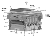
- 1 is a perspective view of an image forming apparatus with an automatic document feeder and a housing removed according to an embodiment of the present invention.
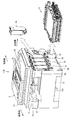
- FIG. 3 is a perspective view of the image forming apparatus illustrating a state in which a toner cartridge is mounted on the cartridge mounting unit illustrated in FIG. 2.
- FIG. 3 is a front view of the image forming main body apparatus as viewed from the right side showing a state in which a toner cartridge is mounted on the cartridge mounting section shown in FIG.
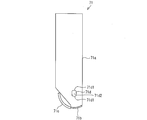
- FIG. 5 is a side view showing the toner cartridge shown in FIG. 4 in a simplified manner.
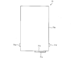
- FIG. 6 is a front view of the toner cartridge shown in FIG. 5.
- FIG. 3 is a front view schematically showing a cartridge mounting portion shown in FIG. 2.
- FIG. 8 is a cross-sectional view taken along line AA in FIG.
- FIG. 6 is an explanatory view showing a state in which the toner cartridge shown in FIG. 5 is moved obliquely downward from above and the fitting convex portion is inserted into the fitting concave portion of the cartridge mounting portion.
- FIG. 6 is an explanatory diagram illustrating a state where the mounting of the toner cartridge illustrated in FIG. 5 to the cartridge mounting unit is completed.
- FIG. 4 is a perspective view of the unit assembly shown in FIG. 3. It is a longitudinal cross-sectional view of the unit assembly shown in FIG. FIG.
- FIG. 5 is an explanatory view showing an open / close state of a side opening / closing door in the image forming main body apparatus shown in FIG. 4.
- 14 (a) is an explanatory view showing another example of the side opening / closing door shown in FIG. 13, and FIG. 14 (b) is an opening of the upper part of the side opening / closing door shown in FIG. 14 (a).
- each replacement or replenishment work object includes the side opening / closing door of the first example and the side opening / closing door of the second example, each replacement or replenishment work object, and image It is explanatory drawing which shows the relationship between the operator's work position with respect to a forming apparatus, the opening amount of a side surface opening / closing door, and the difficulty of work.
- the image forming apparatus according to the embodiment of the present invention includes the side opening / closing door of the third example, each replacement or replenishment work target, the operator's work position with respect to the image forming apparatus, and the opening of the side opening / closing door
- It is explanatory drawing which shows the relationship between quantity and the difficulty of work. It is explanatory drawing which shows the relationship between the paper feed cassette shown in FIG. 1, and a unit assembly.
- FIG. 1 is a longitudinal sectional view showing the internal structure of the image forming main body device 2 when the image forming main body device 2 is viewed from the right side.
- the left side is the front side of the image forming main body apparatus 2
- the right side is the back side.
- the image forming main unit 2 is a full-color printer. Therefore, the image forming main body device 2 prints a color image on a sheet (sheet-like recording medium) according to image data transmitted from the outside.
- the image forming main unit 2 is exemplified as a printer, but it may be a copier, a facsimile machine, or a multifunction machine having these functions. In this case, the image forming main body device 2 prints a multicolor or single color image on a sheet according to image data transmitted from the outside and / or image data read from a document by a scanner.
- the image forming main body device 2 is provided with a unit assembly (required replacement) 11 at the center in the vertical direction.
- a laser optical system unit 12 and a paper feed cassette (a paper feed unit, a replenishment product receiving unit) 13 are provided at a lower position of the unit assembly 11 sequentially from the top.
- a transfer unit 14 is provided at a position on the back side with respect to the unit assembly 11, and a fixing unit 15 is provided above the transfer unit 14.
- An upper surface of the housing of the image forming main body 2 above the unit assembly 11 is a paper discharge tray (paper discharge unit) 16.
- a paper transport path 17 is formed in the path from the paper feed cassette 13 to the paper discharge tray 16, and the paper transport path 17 has a paper feed roller 18, A timing roller 19, the transfer unit 14, the fixing unit 15, and a paper discharge roller 20 are provided.
- the first to fourth image forming units 31 to 34 included in the unit assembly 11 are for yellow, magenta, cyan, and black, respectively.
- the first image forming unit 31 includes a photoreceptor drum 41a, a charger 42a, a developing device 43a, an intermediate transfer roller 44a, and a photoreceptor cleaning device 45a.
- the charger 42a charges the surface of each photosensitive drum 41a to a predetermined potential.
- the developing device 43a develops the electrostatic latent image formed on the surface of the photosensitive drum 41a with toner by exposing the photosensitive drum 41a to the laser light from the laser optical system unit 12.
- the intermediate transfer roller 44 a is disposed on the back surface of the intermediate transfer belt 51, and transfers the toner image formed on the surface of the photosensitive drum 41 a by development onto the surface of the intermediate transfer belt 61 of the intermediate transfer belt unit 35.
- the photoconductor cleaning device 45a removes and collects residual toner and paper dust on the surface of the photoconductor drum 41a after development and image transfer.
- the second image forming unit 32 includes a photoreceptor drum 41b, a charger 42b, a developing device 43b, an intermediate transfer roller 44b, and a photoreceptor cleaning device 45a.
- the third image forming unit 33 includes a photoreceptor drum 41c, a charger 42c, a developing device 43c, an intermediate transfer roller 44c, and a photoreceptor cleaning device 45c.
- the fourth image forming unit 34 includes a photoreceptor drum 41d, a charger 42d, a developing device 43d, an intermediate transfer roller 44d, and a photoreceptor cleaning device 45d.
- the intermediate transfer belt unit 35 includes an intermediate transfer belt 51, a driving roller 52 that supports the intermediate transfer belt 51, a driven roller 53, and tension rollers 54 and 55.
- the transfer belt cleaning device 36 removes residual toner and paper dust from the surface of the intermediate transfer belt 51.
- the laser optical system unit 12 includes laser light sources 12a to 12d corresponding to the respective photosensitive drums 41a to 41d, and irradiates the photosensitive drums 41a to 41d with laser light from the laser light sources 12a to 12d, and the image forming main body 2
- the electrostatic latent images corresponding to the image to be printed are formed on the surfaces of the photosensitive drums 41a to 41d.
- the transfer unit 14 includes a transfer roller 14 a that is pressed against the drive roller 52 of the intermediate transfer belt unit 35 via the intermediate transfer belt 51, and a sheet on which the toner image on the surface of the intermediate transfer belt 51 is supplied from the paper feed cassette 13. Transcript to.
- the fixing unit 15 includes a fixing roller 15a and a pressure roller 15b, and melts and fixes the toner image on the paper to the paper.
- the laser optical system unit 12 irradiates the photosensitive drums 41a to 41d with laser light according to the input image data, and the photosensitive drums 41a to 41d.
- An electrostatic latent image is formed at 41d.
- These electrostatic latent images are developed with toner supplied from the developing devices 43a to 43d, and yellow, magenta, cyan, and black toner images are formed on the surfaces of the photosensitive drums 41a to 41d, respectively.
- These toner images are transferred to the same position on the intermediate transfer belt 51 of the intermediate transfer belt unit 35 so as to overlap each other, and further transferred onto the paper in the transfer unit 14.
- the sheet is fed from the sheet feeding cassette 13 to the sheet conveying path 17 by the sheet feeding roller 18, and is supplied to the transfer unit 14 by the timing roller 19 at a timing coincident with the toner image on the intermediate transfer belt 51.
- the sheet on which the toner image is transferred in the transfer unit 14 is conveyed to the fixing unit 15, and the toner image is fixed on the sheet in the fixing unit 15. Thereafter, the paper is discharged onto the paper discharge tray 16 by the paper discharge roller 20.
- the fixing unit 15 since the fixing unit 15 is located on the back side, the heat (hot air) generated in the fixing unit 15 is transmitted to the user located on the front side of the image forming apparatus 1. Will never feel uncomfortable.
- FIG. 2 is a perspective view of the image forming apparatus 1 in a state where the automatic document feeder 3 is provided and the housing is removed according to the embodiment of the present invention.
- the paper feed cassette 13 shown in FIG. 2 can be pulled out to the front side of the image forming apparatus 1 (image forming main body apparatus 2) by pulling the handle 13a.
- the image forming apparatus 1 includes an operation panel 21 at the upper part of the position on the front side.
- the cartridge mounting portions 65 to 68 have a vertically long shape in the vertical direction, and are arranged in the front-rear direction of the image forming apparatus 1 at the same height position.
- the cartridge mounting portions 65 to 68 have a structure in which adjacent ones are connected and integrated, and are provided corresponding to the developing devices 43a to 43d, respectively.
- FIG. 3 is a perspective view of the image forming apparatus 1 showing a state in which the toner cartridges 71 to 74 are mounted on the cartridge mounting portions 65 to 68 shown in FIG.
- FIG. 4 is a front view of the image forming main body 2 viewed from the right side showing the state where the toner cartridges 71 to 74 are mounted on the cartridge mounting portions 65 to 68 shown in FIG.
- the toner cartridges 71 to 74 contain yellow, magenta, cyan and black toners, respectively. When the toner cartridges 71 to 74 are mounted in the cartridge mounting portions 65 to 68, the toner can be supplied to the corresponding developing devices 43a to 43d, respectively.
- the toner cartridges 71 to 74 forming a group are arranged on the right surface side of the image forming main body device 2 at a position closer to the front side with respect to the center position in the front-rear direction of the image forming main body device 2.
- FIG. 5 is a side view showing the toner cartridge 71 shown in FIG. 4 in a simplified manner.
- 6 is a front view of the toner cartridge 71 shown in FIG. 5
- FIG. 7 is a front view schematically showing the cartridge mounting portion 65 shown in FIG. 2
- FIG. 8 is a cross-sectional view taken along the line AA in FIG. FIG.
- the toner cartridge 71 is formed in a vertically long shape in the vertical direction, and includes a toner storage portion 71a for storing the toner therein.
- a toner supply port 71b is formed at the lower end of the toner storage portion 71a, and a shutter 71c that opens and closes the toner supply port 71b is provided.
- the lower end surface where the toner supply port 71b is formed is curved in an arc shape, and the shutter 71c is formed in an arc shape correspondingly.
- the shutter 71c is closed by the action of a spring (not shown) in a normal state where the toner cartridge 71 is not mounted on the cartridge mounting portion 65.
- fitting convex portions 71d are provided on the toner supply port 71b and at positions below the toner cartridge 71 near the position of the toner supply port 71b. That is, one fitting convex portion 71 d projects in the front direction of the image forming main body device 2, and the other fitting convex portion 71 d projects in the rear direction of the image forming main body device 2.
- the upper and lower surfaces of the fitting convex portion 71d are arcuate curved surfaces 71d1, and the space between the upper and lower curved surfaces 71d1 is a straight portion 71d2 having a width narrower than the width between both curved surfaces 71d1.
- the cartridge mounting portion 65 has a cartridge facing portion 65 c arranged vertically along the right surface of the image forming main body device 2.
- convex wall portions 65a are provided at the left and right positions near the lower end portion of the cartridge facing portion 65c (the front direction position and the back direction position with respect to the image forming main body device 2).
- fitting concave portions 65b are formed on the inner surfaces facing each other.
- the fitting recess 65b has a straight recess 65b2 at the introduction portion and a circular recess 65b1 at the end of the fitting recess 65b.
- the straight concave portion 65b2 is slightly wider than the straight portion 71d2 in the fitting convex portion 71d of the toner cartridge 71, and the circular concave portion 65b1 is between the curved surfaces 71d1 in the fitting convex portion 71d of the toner cartridge 71.
- the diameter is slightly wider than the width.
- the straight recess 65b2 is inclined to the right surface side of the image forming main body device 2 with respect to the vertical vertical direction.
- the operator first moves the toner cartridge 71 obliquely downward from above with respect to the cartridge mounting portion 65, and the straight shape of the fitting convex portion 71d.
- the portion 71d2 is inserted into the straight recess 65b2 of the fitting recess 65b.
- the toner cartridge 71 is moved obliquely downward until the fitting convex portion 71d reaches the circular concave portion 65b1 of the fitting concave portion 65b.
- the toner cartridge 71 is rotated until the toner cartridge 71 contacts the cartridge facing portion 65c of the cartridge mounting portion 65.
- the rotation of the toner cartridge 71 can be smoothly performed because the fitting convex portion 71d is rotatably held in the circular concave portion 65b1 of the fitting concave portion 65b.
- toner intermediate receiving members 76 to 79 are disposed below the toner cartridges 71 to 74 mounted on the cartridge mounting portions 65 to 68, respectively.
- end portions of toner take-in portions 43a1 to 43d1 of the developing devices 43a to 43d are arranged, respectively. Therefore, the toner in the toner cartridges 71 to 74 is supplied to the corresponding developing devices 43a to 43d via the toner intermediate receiving members 76 to 79, respectively.
- the configuration for replenishing toner from the toner cartridge 71 to the developing device 43a will be described taking the case of the toner cartridge 71, the cartridge mounting portion 65, the toner intermediate receiving member 76, and the developing device 43a as an example.
- FIG. 9 is an explanatory diagram showing a state in which the toner cartridge 71 is moved obliquely downward from above and the fitting convex portion 71d of the toner cartridge 71 is inserted into the fitting concave portion 65b of the cartridge mounting portion 65.
- FIG. 10 is an explanatory view showing a state where the mounting of the toner cartridge 71 to the cartridge mounting portion 65 is completed.
- the toner intermediate receiving member 76 has a toner intake port 76a.
- the position of the toner intake port 76a is a position facing the toner supply port 71b of the toner cartridge 71 in a state where the toner cartridge 71 is mounted on the cartridge mounting unit 65.
- the shutter 71c of the toner cartridge 71 is formed with an engaging convex portion 71e, and the toner intermediate receiving member 76 has an engaging receiving portion 76b that engages with the engaging convex portion 71e. Is formed.
- the shutter 71c is opened and the toner supply port 71b is opened.
- the toner in the toner cartridge 71 is supplied to the toner supply port 71b, the toner intake port 76a of the toner intermediate receiving member 76, the toner intermediate receiving member 76, the toner supply port 76c of the toner intermediate receiving member 76, and the toner intake.
- the toner is supplied to the developing device 43a through the toner intake 43a2 of the portion 43a1.
- the waste toner container 69 has a thin rectangular box shape and can be easily attached to and detached from the image forming main body device 2.
- the waste toner container 69 stores waste toner and paper powder collected by each cleaning device of the unit assembly 11.
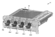
- the unit aggregate 11 has a configuration shown in FIGS. 11 and 12 in the present embodiment.
- FIG. 11 is a perspective view showing the unit assembly 11, and
- FIG. 12 is a longitudinal sectional view of the unit assembly 11 shown in FIG.
- the waste toner transport pipe 36a connected to the transfer belt cleaning device 36 and the waste toner transport pipes 45a1 to 45d1 connected to the photoconductor cleaning devices 45a to 45d are formed. Projecting to the right side of the main unit 2. These waste toner conveying pipes 36a and 45a1 to 45d are connected to the waste toner container 69 when the waste toner container 69 is attached to the image forming main body apparatus 2.
- the unit assembly 11 includes first to fourth image forming units 31 to 34, an intermediate transfer belt unit 35, and a transfer belt cleaning device 36.
- the first image forming unit 31 includes a developing device 43a and a first process unit 201a
- the second image forming unit 32 includes a developing device 43b and a second process unit 201b
- the third image forming unit 33 includes a developing device 43c and a first process unit 201b
- the fourth image forming unit 34 includes a developing device 43d and a fourth process unit 201d.
- the first to fourth process units 201a to 201d are provided with at least a photosensitive drum.
- the first process unit 201a includes a photoreceptor drum 41a, a charger 42a, an intermediate transfer roller 44a, and a photoreceptor cleaning device 45a.
- the second process unit 201b includes a photoconductor drum 41b, a charger 42b, an intermediate transfer roller 44b, and a photoconductor cleaning device 45b.
- the third process unit 201c includes a photoreceptor drum 41c, a charger 42c, an intermediate transfer roller 44c, and a photoreceptor cleaning device 45c.
- the fourth process unit 201d includes a photoreceptor drum 41d, a charger 42d, an intermediate transfer roller 44d, and a photoreceptor cleaning device 45d.
- the unit assembly 11 is exchanged for a new one after a predetermined number of prints, for example.
- the unit assembly 11 can be removed from and inserted into the right side of the image forming main body device 2 (the front side in FIG. 1) with respect to the image forming main body device 2.
- the unit assembly 11 may have the following forms (1) to (4).
- An image forming unit configured by connecting a plurality of process units (image forming units) including at least a photosensitive drum and an intermediate transfer unit (for example, an intermediate transfer belt unit 35) integrally connected
- image forming units including at least a photosensitive drum and an intermediate transfer unit (for example, an intermediate transfer belt unit 35) integrally connected
- the image forming unit constituting the unit aggregate 11 in combination with the intermediate transfer unit is not limited to one using two color toners, and may use three or four color toners. .
- An apparatus including an intermediate transfer unit and a process unit This includes, for example, an intermediate transfer unit and an image forming unit configured by connecting a process unit that uses toner of at least two colors. is there.
- the image forming unit is not limited to one using two color toners, and may use three or four color toners.
- An apparatus including an intermediate transfer unit, a process unit, and a developing unit.
- This includes, for example, an intermediate transfer unit, a process unit that uses toner of at least two colors, and a developing unit (developing device).
- the pair of the developing unit and the process unit is not limited to one using two color toners, and may use three color or four color toners.
- An intermediate transfer unit, a process unit, a developing unit, and an exposure unit This includes, for example, an intermediate transfer unit, a process unit that uses toner of at least two colors, a developing unit, and an exposure unit (for example, a laser optical system unit). 12).
- an intermediate transfer unit for example, a process unit that uses toner of at least two colors
- a developing unit for example, a laser optical system unit. 12
- an exposure unit for example, a laser optical system unit. 12
- the combination of the development unit, the process unit, and the image exposure unit is not limited to one using two color toners, and may use three or four color toners.
- FIG. 13 is an explanatory view showing an open / closed state of the side opening / closing door 101.
- the side opening / closing door 101 covers the arrangement area of the toner cartridges 71 to 74 and the waste toner container 69 so as to be openable and closable.
- the side opening / closing door 101 has a handle 101a and can be opened / closed in the vertical direction around the rotation fulcrum shaft 102 at the lower end.
- the side opening / closing door 101 can be opened from the closed position 101a0 to the first open position (small open position) 101a1 and the second open position (large open position) 101a2.
- the toner cartridges 71 to 74 can be replaced at the first opening position 101a1, and the waste toner container 69 and the unit assembly 11 can be replaced at the second opening position 101a2.
- the opening angle (first opening angle) of the first opening position 101a1 with respect to the closing position 101a0 is, for example, 30 ° to 45 °
- the opening angle (second opening angle) of the second opening position 101a2 is, for example, 90 ° to 110. °.
- the image forming apparatus 1 may include a side opening / closing door 131 shown in FIGS. 14 (a) to 14 (b) instead of the side opening / closing door 101 shown in FIG. 14A is an explanatory view showing another example of the side opening / closing door 101 shown in FIG. 13, and FIG. 14B is an upper part of the side opening / closing door 131 shown in FIG. 14A. It is explanatory drawing which shows the state which open
- the side opening / closing door 131 includes a door upper part 132 and a door lower part 133, and the door upper part 132 and the door lower part 133 are connected to an opening / closing auxiliary member (connection member) 134 and a hinge (connection). Member) 135.
- a handle 131a is formed on the door upper portion 132.
- the material of the opening / closing auxiliary member 134 may be an elastic rubber such as NBR (Nitrile butadiene rubber) or a PET (Polyethylene terephthalate) film having a thickness of about 0.3 mm.
- the door upper portion 132 and the door lower portion 133 are connected by an opening / closing auxiliary member 134 on the inner surface side and are connected by a hinge 135 on the outer surface side.
- the opening / closing auxiliary member 134 is attached to the door upper part 132 and the door lower part 133 by screws 135.
- a long hole 134 a may be formed in a portion of the opening / closing auxiliary member 134 attached to the door upper part 132 or the door lower part 133. This is because when the door upper part 132 is opened, the opening / closing auxiliary member 134 can be moved relative to the screw 135 so that the door upper part 132 can be opened smoothly.
- the opening angle of the door upper part 132 and the door lower part 133 is 90 ° to 110 ° as in the case of opening the side opening / closing door 101 to the second opening position 101a2.
- the opening angle of the door upper portion 132 may be 60 ° to 70 °, for example.
- the opening angle of the door upper portion 132 can be adjusted by adjusting the length of the elongated hole 134a of the opening / closing auxiliary member 134.
- the side opening / closing door 131 is opened when the side opening / closing door 131 (door upper portion 132) is opened in order to attach / detach the toner cartridges 71 to 74 to / from the image forming apparatus 1.
- the rotation area can be reduced. As a result, the working space on the side of the image forming apparatus 1 required when the toner cartridges 71 to 74 are attached and detached can be further reduced.
- the side surface opening / closing door 101 may be opened at three stages of first to third opening angles.
- the image forming main body 2 opens the side opening / closing door 101 at three angles, that is, from the closed position 101b0 to the first open position (small open position) 101b1, the second open position (medium open position) 101b2, and the third.
- An opening angle adjusting mechanism 151 that opens to an opening position (large opening position) 101b3 is provided.
- FIG. 15 is an explanatory diagram showing a state of the opening angle adjusting mechanism 151 when the side opening / closing door 101 is in the closed position 101b0.
- FIG. 16 is an explanatory diagram illustrating a state of the opening angle adjustment mechanism 151 when the side opening / closing door 101 is opened to the first opening position 101b1.
- FIG. 17 is an explanatory diagram showing a state of the opening angle adjusting mechanism 151 when the side opening / closing door 101 is opened to the second opening position 101b2.
- FIG. 18 is an explanatory diagram showing a state of the opening angle adjusting mechanism 151 when the side opening / closing door 101 is opened to the third opening position 101b3.
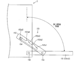
- the opening angle adjusting mechanism 151 includes an opening angle adjusting member 152 having an elongated plate shape.
- the material of the opening angle adjusting member 152 is, for example, a metal such as PET (Polyethylene terephthalate), ABS (acrylonitrile butadiene styrene), iron, or SUS.
- the opening angle adjusting mechanism 151 is disposed in the front-rear direction of the image forming main body 2 inside the image forming main body 2, and the rear end is rotatably connected to the side surface of the side opening / closing door 101 by the shaft member 153. Has been.
- a guide hole 152a extending in the left-right direction of the image forming main body device 2 is formed in the opening angle adjusting member 152, and a guide pin 154 fixed to the image forming main body device 2 is inserted into the guide hole 152a.
- the lower side of the opening angle adjusting member 152 around the guide hole 152a has a linear shape.
- the upper side of the guide hole 152a is directed from the right end portion (end portion on the side surface opening / closing door 101 side) of the guide hole 152a toward the left end portion, the first guide portion 152a1, the first locking portion 152a2, and the second guide portion 152a3.
- locking part 152a4 is formed.
- the left end portion (terminal portion) of the guide hole 152a that is further leftward than the second locking portion 152a4 is a third locking portion 152a5.
- the first guide part 152a1 and the second guide part 152a3 are horizontal after being inclined obliquely upward.
- the first locking portion 152a2 and the second locking portion 152a4 extend downward from the terminal ends of the first guide portion 152a1 and the second guide portion 152a3.
- a guide pin 154 is engaged with the first locking portion 152a2, the second locking portion 152a4, and the second guiding portion 152a3, and the opening angle adjustment to the right side of the image forming main body device 2 with the opening of the side opening / closing door 101 is adjusted. The movement of the member 152 is prevented.
- the toner cartridges 71 to 74 are used when the toner stored therein is empty, the waste toner container 69 is used when the collected waste toner is full, and the unit assembly 11 is For example, when the number of printed sheets reaches a predetermined number, each is replaced with a new one based on the display on the operation panel 21, for example.
- the replacement cycle of the toner cartridges 71 to 74, the waste toner container 69 and the unit assembly 11 is approximately when converted to the number of printed sheets.
- Toner cartridges 71 to 74 Every 4,000 sheets
- Waste toner container 69 Every 10,000 sheets
- Unit aggregate 11 Every 60,000 sheets (Toner cartridge replacement work)
- the operator reaches for the right side of the image forming apparatus 1 at the position on the front side of the image forming apparatus 1 and pulls the handle 101 a of the side opening / closing door 101 to pull the side opening / closing door 101. Open to the first opening position 101a1.
- the operator starts from the position where the toner cartridge 71 is mounted on the cartridge mounting portion 65 (installation completed state) as illustrated in FIG. 9. Then, the toner cartridge 71 is rotated rightward (clockwise) around the fitting convex portion 71d.
- the operator moves the toner cartridge 71 obliquely upward in the angle state shown in FIG.
- the fitting convex portion 71 d of the toner cartridge 71 is removed from the fitting concave portion 65 b of the cartridge mounting portion 65.
- the shutter 71c is closed and the toner supply port 71b is closed.
- the operator may perform the operation opposite to the above-described operation for removing the toner cartridge 71 to bring the toner cartridge 71 into the mounting completion state shown in FIG.
- the operator removes the toner cartridges 71 to 74, the cartridge mounting portions 65 to 68, the waste toner container 69 and the like existing on the right side of the unit assembly 11 from the image forming main body 2, and then the unit assembly 11. Is pulled out from the image forming main unit 2 and replaced with a new one.
- the worker may perform work on the right side when the work space can be secured on the right side of the image forming main body device 2.
- the image forming main body device 2 may be rotated 90 degrees horizontally so that the right side of the image forming main body device 2 is on the front (front) side.
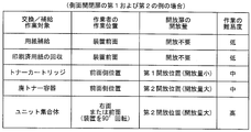
- FIG. 19 shows the replacement or replenishment work target when the image forming apparatus 1 includes the side opening / closing door 101 of the first example and when the image forming apparatus 1 includes the side opening / closing door 131 of the second side example.
- 4 is an explanatory diagram showing a relationship among a worker's work position with respect to the image forming apparatus 1, a side door opening amount, and a work difficulty level.
- FIG. 20 shows each replacement or replenishment work target, the operator's work position with respect to the image forming apparatus 1, and the side opening / closing door when the image forming apparatus 1 includes the side opening / closing door 101 of the third example. It is explanatory drawing which shows the relationship between the amount of open
- front position the difference between the “front position” and the “front side position” is that the operator can work on the front side while being positioned on the front side of the image forming apparatus 1 as the “front position”.
- a case where the work is performed on the side surface of the image forming apparatus 1 while being located on the front surface of the image forming apparatus 1 is referred to as “front surface side position”.
- the replacement or replenishment work targets are arranged in the order of high work frequency (replenishment or replacement frequency) from top to bottom.
- high work frequency freshness or replacement frequency
- the operation frequency of “paper supply” is relatively high.
- the operator can perform the operation by pulling out the paper feed cassette 13 forward, replenishing paper, and pushing back the paper feed cassette 13 at the front position of the image forming apparatus 1. Therefore, the difficulty level of the “paper supply” operation is low.
- the operation frequency of “collection of printed paper” is relatively high, and is equal to or around the operation frequency of “paper supply” depending on the usage state of the image forming apparatus 1. In this operation, the operator can collect printed sheets discharged from the back side of the image forming apparatus 1 onto the discharge tray 16 at the front position of the image forming apparatus 1. Therefore, the difficulty level of the “collection of printed paper” is low.
- the work frequency of exchanging the toner cartridges 71 to 74 is medium among the work objects listed in FIGS.
- the operator reaches for the right side of the image forming apparatus 1 at the position on the front side of the image forming apparatus 1, opens the side opening / closing door 101 or the side opening / closing door 131, and replaces the toner cartridges 71 to 74. can do.
- the side opening / closing door 101 (first example, third example) is opened to the first opening positions 101a1, 101b1 (small opening position), and the side opening / closing door 131 (second example) is the door. Only the upper part 132 is opened. That is, the opening amount of each of the side opening doors of the first to third examples is small. Therefore, if a relatively small space can be secured on the side of the image forming apparatus 1 so that the side opening / closing door 101 or the side opening / closing door 131 can be opened to a small opening amount, the operator does not move to the right side of the image forming apparatus 1. In addition, the toner cartridges 71 to 74 can be replaced.
- the side opening / closing doors 101 and 131 may be formed on the left side of the image forming apparatus 1.
- the side doors 101 and 131 are formed on the right side of the image forming apparatus 1, a right-handed person who is said to have a population ratio of about 70% needs to replace the toner cartridges 71 to 74. It can be done easily with the dominant hand. In view of the above, the difficulty of exchanging the toner cartridges 71 to 74 is moderate.
- the work frequency of replacing the waste toner container 69 is lower than the work frequency of replacing the toner cartridges 71 to 74, but is moderate among the work objects listed in FIGS.
- the operator reaches for the right side of the image forming apparatus 1 at the position on the front side of the image forming apparatus 1, opens the side opening / closing door 101 or the side opening / closing door 131, and replaces the waste toner container 69. be able to.
- the side opening / closing door 101 of the first example opens to the second opening position 101a2 (large opening position), and the side opening / closing door 131 of the second example opens the door upper part 132 and the door lower part 133 (
- the side opening / closing door 101 of the third example is opened to the second opening position 101b2 (medium opening position). That is, the side opening doors of the first and second examples both have a large opening amount, and the side opening door of the third example has a middle opening amount.
- the side opening / closing doors 101 and 131 are formed on the right side of the image forming apparatus 1, a right-handed person who is said to have a population ratio of about 70% is a dominant hand for replacing the waste toner container 69. Can be easily performed. From the above points, the difficulty of replacing the waste toner container 69 is medium.
- the replacement frequency of the unit assembly 11 is relatively high.
- the operator turns around the right surface of the image forming apparatus 1 or rotates the image forming apparatus 1 by 90 ° so that the right surface of the image forming apparatus 1 is in front.
- the unit assembly 11 can be exchanged by opening the side opening / closing door 101 or the side opening / closing door 131.
- the side opening / closing door 101 of the first example opens to the second opening position 101a2 (large opening position), and the side opening / closing door 131 of the second example opens the door upper part 132 and the door lower part 133 (
- the side opening / closing door 101 of the third example is opened to the third opening position 101b3 (large opening position). That is, the side opening doors of the first to third examples all have a large opening amount. From the above points, the difficulty of exchanging the unit assembly 11 is high.
- the arrangement position of the work object is set according to the work frequency of the work object to be replaced or replenished. Specifically, replacement or replenishment work objects are arranged such that the higher the work frequency, the lower the work difficulty. Thus, the workability of the image forming apparatus 1 including the replenishment work, the consumables replacement work, and the unit assembly replacement work is improved.
- the toner cartridges 71 to 74, the waste toner container 69, and the unit assembly 11 can be replaced by opening the same side opening / closing door 101. Therefore, these operations can be easily performed. it can. In addition, since the number of doors required for the image forming apparatus 1 can be reduced, the structure of the image forming apparatus 1 can be simplified.
- the side opening / closing door 101 is opened to the first opening positions 101a1 and 101b1, or the upper door 132 of the side opening / closing door 131 is opened obliquely. Then, after the toner cartridges 71 to 74 are inserted into the image forming apparatus 1 by moving obliquely downward from above, the toner cartridges 71 to 74 are rotated in the direction of the image forming apparatus 1 (counterclockwise). It is like that.
- the toner cartridges 71 to 74 are attached to the image forming apparatus 1 by attaching the toner cartridges 71 to 74 to the side opening / closing door 101 and then closing the side opening / closing door 101 to bring the toner cartridges 71 to 74 to a predetermined mounting position. It is not something to wear. Accordingly, when the side opening / closing door 101 is deformed with the passage of time and the side opening / closing door 101 is closed, there is no problem that the toner cartridges 71 to 74 are not easily mounted at predetermined mounting positions.
- the side opening / closing doors 101 and 131 are opened and the cartridge attachment portions 65 to 68 are not rotated to a position where the insertion of the toner cartridges 71 to 74 is received.
- the opening angle of the side opening / closing doors 101 and 131 can be reduced, and this also enables work in a narrow work area.
- the image forming apparatus 1 of the present embodiment can easily replace the toner cartridges 71 to 74, the waste toner container 69, and the unit assembly 11, and suppresses the number of necessary opening / closing doors.
- the structure can be simplified.
- the image forming apparatus 5 has the following differences from the image forming apparatus 1 described above.
- the image forming apparatus 1 is the same as the image forming apparatus 1 described in the first embodiment except for the following differences.
- FIG. 2 is a perspective view of the image forming apparatus 5 with the automatic document feeder 3 and the housing removed, according to the embodiment of the present invention.
- the paper feed cassette 13 is provided below the image forming apparatus 5 and can be pulled out to the front side of the image forming apparatus 5 (image forming main body apparatus 2) by pulling the handle 13a.
- the image forming apparatus 5 includes an operation panel 21 at an upper position on the front side.
- the toner cartridges 71 to 74 have a vertically long shape that is long in the vertical direction, and accommodate yellow, magenta, cyan, and black toner, respectively.
- the toner cartridges 71 to 74 are mounted in the cartridge mounting portions 65 to 68, the toner can be supplied to the corresponding developing devices 43a to 43d, respectively.
- the toner cartridges 71 to 74 and the waste toner container 69 can be replaced by opening the side opening / closing door 101.
- the side opening / closing door 101 is formed on the right side of the housing of the image forming main body device 2.
- FIG. 13 is an explanatory view showing an open / closed state of the side opening / closing door 101.
- the side opening / closing door 101 has a handle 101a and can be opened / closed in the vertical direction around the rotation fulcrum shaft 102 at the lower end.
- the toner cartridges 71 to 74 are attached / detached by opening the side opening / closing door 101 from the closed position 101a0 to the first open position (small open position) 101a1.
- the toner cartridges 71 to 74 are mounted on the image forming main body apparatus 2 by moving obliquely downward from above, and then rotated to a standing state.
- the toner cartridges 71 to 74 are removed from the image forming main body device 2 by the reverse operation.
- the attachment / detachment of the waste toner container 69 is performed by opening the side opening / closing door 101 from the closed position 101a0 to the second open position (large open position) 101a2.
- the unit assembly 11 is disposed on the paper feed cassette 13 in the image forming main body device 2 (image forming device 5).
- the unit assembly 11 is attached / detached by opening the side opening / closing door 101 to the second opening position 101a2 shown in FIG.
- the toner cartridges 71 to 74, the waste toner container 69, and the like are removed prior to attachment / detachment of the unit assembly 11, the toner cartridges 71 to 74, the waste toner container 69, and the like are removed. That is, the unit assembly 11 is attached to and detached from the image forming main body device 2 from the right side of the image forming main body device 2.
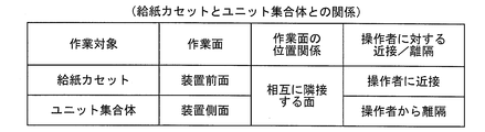
- FIG. 21 is an explanatory diagram showing the relationship between the paper feed cassette 13 and the unit assembly 11.
- the work surface when replenishing paper to the paper feed cassette 13 is the front surface of the image forming apparatus 5 (the front surface of the apparatus), and the work surface when attaching and detaching the unit assembly 11 is image formation. It is the right side surface (device side surface) of the device 5.
- the positional relationship between these two work surfaces is a surface adjacent to each other.
- the work surface (the front surface of the apparatus) of the paper feed cassette 13 is a surface close to an operator located on the front surface of the apparatus, and the work surface (the device side surface) of the unit assembly 11 is from an operator located on the front surface of the apparatus. It is a surface that is separated.
- the direction in which the paper feed cassette 13 is taken in and out of the image forming apparatus 5 is a direction perpendicular to the front surface of the image forming apparatus 5.
- the direction in which the unit assembly 11 is attached to and detached from the image forming apparatus 5 is a direction perpendicular to the side surface (right side surface) of the image forming apparatus 5.
- the paper cassette 13 and the unit assembly 11 do not interfere with each other and both operations can be performed smoothly. Can be done.
- the image forming apparatus includes, as a working unit, an image forming apparatus including a replenishment receiving unit, a replacement required to be replaced, and an image forming unit that forms a toner image.
- a replenishment receiving part, an attaching / detaching part for exchanging the exchangeable parts, and an attaching / detaching part for exchanging the image forming unit are arranged separately on the front surface and the side surface of the image forming apparatus.
- a high-frequency work section with a relatively high frequency of replenishment work or replacement work is arranged on the front surface
- a low-frequency work section with a relatively low work frequency is arranged on the side surface.
- the high-frequency work unit having a relatively high frequency of replenishment work or exchange work among the parts of the replenishment receiving part, the replacement part attaching / detaching part, and the image forming unit attaching / detaching part.
- a low-frequency work unit that is disposed on the front surface of the image forming apparatus and has a relatively low work frequency is disposed on the side surface of the image forming apparatus.
- the worker can perform a work with a relatively high frequency among the replenishment work for the replenishment receiving part, the replacement work for the replacement parts, and the replacement work for the image forming unit. This is easily performed with a relatively low degree of difficulty with respect to the high-frequency work unit arranged in (1).
- the worker performs a task with a relatively low work frequency with a relatively high degree of difficulty with respect to the low-frequency work unit disposed on the side surface of the image forming apparatus. .
- the image forming apparatus has good workability as viewed from the whole work including the replenishment work, the consumables replacement work, and the image forming unit replacement work.
- the side surface of the image forming apparatus includes a first low-frequency work unit in which an operator performs work from a front position of the image forming apparatus, and a work frequency is higher than that of the first low-frequency work unit.
- a low configuration may be employed in which a second low-frequency work unit that performs work from the side surface position of the image forming apparatus is arranged by an operator.
- the first low-frequency working unit for example, the working unit for exchanging the toner cartridge, or for exchanging the waste toner container
- the worker can work from the position on the front surface of the image forming apparatus.
- a second low-frequency work unit having a work frequency lower than that of the first low-frequency work unit for example, a work unit for exchanging the image forming unit (unit assembly)
- the worker goes to the side of the image forming apparatus. Work from that position.
- the operation is performed by rotating the image forming apparatus by 90 ° so that the worker positioned at the front surface position of the image forming apparatus faces the side surface of the image forming apparatus.
- the low-frequency work unit arranged on the side surface of the image forming apparatus can easily work on the first low-frequency work unit having a relatively high work frequency.
- a side opening / closing door that can be opened to a small opening position having a relatively small opening angle and a large opening position having a relatively large opening angle is formed on the side surface of the housing of the image forming apparatus.
- the work for the first low-frequency work unit is performed by opening the side opening / closing door to the small open position, and the work for the second low-frequency work unit is set to the large open position. It is good also as a structure which opens and is performed.
- the work on the first low-frequency work unit is performed by the operator by opening the side opening / closing door from the front position of the image forming apparatus to the small open position. Further, the work on the second low-frequency work unit is performed by the operator opening the side opening / closing door to the large open position from the side position of the image forming apparatus, that is, in a state where the operator faces the side face of the image forming apparatus. Done.
- work on the high-frequency work unit arranged on the front surface of the image forming apparatus is performed without opening the side opening / closing door.
- the work on the replenishment receiving part, the attaching / detaching part for exchanging necessary replacement parts, and the attaching / detaching part for exchanging the image forming unit can be efficiently performed with lower difficulty as the work frequency increases.
- the high-frequency work unit is a paper discharge unit that discharges printed paper and a paper feed unit in which printing paper is arranged
- the first low-frequency work unit includes:
- the toner cartridge mounting unit may be configured such that the second low-frequency working unit is an image forming unit mounting unit.
- the operation for the toner cartridge mounting portion which is the first low-frequency operation portion, that is, the toner cartridge replacement operation, is performed by the operator by opening the side opening door from the front position of the image forming apparatus to the small open position. Is called.
- the work for the mounting portion of the image forming unit, which is the second low-frequency work section, that is, the replacement operation of the image forming unit is performed by the operator from the side position of the image forming apparatus, that is, the operator In a state of facing, the side opening / closing door is opened to the large open position.
- the higher the work frequency the lower the difficulty of collecting printed paper from the paper discharge unit, supplying paper for printing to the paper supply unit, replacing the toner cartridge, and replacing the image forming unit. Can be performed efficiently at a degree.
- the side surface of the image forming apparatus includes a first low-frequency work unit in which an operator performs work from a front position of the image forming apparatus, and a work frequency is higher than that of the first low-frequency work unit.
- a second low-frequency work unit that is operated by the operator from the side surface position of the image forming apparatus, and a work frequency is lower than the first low-frequency work unit and higher than the second low-frequency work unit.
- a third low-frequency work unit that is operated by the worker from the side surface position of the image forming apparatus is disposed, and the side surface of the housing of the image forming apparatus has a small opening position and a small opening position with a relatively small opening angle.
- a side opening door that can be opened to a middle opening position having a large opening position with a relatively large angle and an opening angle larger than the small opening position and smaller than the large opening position is formed.
- Work on The side opening / closing door is opened to the small opening position, and the operation for the second low-frequency operation unit is performed by opening the side opening / closing door to the large opening position, and the third low-frequency operation is performed.
- the operation on the part may be performed by opening the side opening / closing door to the middle open position.
- the work on the first low-frequency work unit is performed by the operator by opening the side opening / closing door from the front position of the image forming apparatus to the small open position.
- the work on the second low-frequency work unit is performed by the operator opening the side opening / closing door to the large open position from the side position of the image forming apparatus, that is, in a state where the operator faces the side face of the image forming apparatus. Done.
- the work on the third low-frequency work unit is performed by the operator by opening the side opening / closing door from the front position of the image forming apparatus to the middle open position.
- work on the high-frequency work unit arranged on the front surface of the image forming apparatus is performed without opening the side opening / closing door.
- the work on the replenishment receiving part, the attaching / detaching part for exchanging necessary replacement parts, and the attaching / detaching part for exchanging the image forming unit can be efficiently performed with lower difficulty as the work frequency increases.
- the high-frequency work unit is a paper discharge unit that discharges printed paper and a paper feed unit in which printing paper is arranged
- the first low-frequency work unit includes:
- the toner cartridge mounting unit may be configured such that the second low frequency working unit is an image forming unit mounting unit and the third low frequency working unit is a waste toner container mounting unit.
- the operation for the toner cartridge mounting portion which is the first low-frequency operation portion, that is, the toner cartridge replacement operation, is performed by the operator by opening the side opening door from the front position of the image forming apparatus to the small open position. Is called.
- the work on the mounting portion of the image forming unit which is the second low-frequency work portion, that is, the replacement operation of the image forming unit, is performed by the worker from the side surface position of the image forming apparatus, that is, In a state of facing, the side opening / closing door is opened to the large open position.
- the operator opens the side opening / closing door from the front position of the image forming apparatus to the middle open position. Done.
- the operation of collecting printed paper from the paper discharge unit, the operation of supplying printing paper to the paper supply unit, the operation of replacing the toner cartridge, the operation of replacing the image forming unit, and the operation of replacing the waste toner container are performed.
- a developer image is formed on each photoconductor by performing an electrophotographic process by a plurality of process units corresponding to each color provided with the photoconductor, and the developer images of the respective colors. Is transferred onto the intermediate transfer body of the intermediate transfer unit from the photoconductor to form a multicolor developer image, and the multicolor developer image is transferred from the intermediate transfer body onto a sheet.
- a unit assembly including an image forming unit having the plurality of process units and the intermediate transfer unit, wherein either one of a front surface of the image forming apparatus and a side surface adjacent to the front surface is the unit assembly.
- a work surface for attaching and detaching the body, and the other surface is a work surface for containing the paper and for taking in and out a paper feed tray stored in the image forming apparatus. .
- one of the front surface of the image forming apparatus and the side surface adjacent to the front surface is a work surface for attaching and detaching the unit assembly, and the other surface is the paper feed tray. It is a work surface to be taken in and out.
- a unit assembly including an image forming unit having a plurality of process units and an intermediate transfer unit is larger than each image forming unit, but is attached and detached on a work surface different from the work surface of the paper feed tray. Therefore, a space for performing the attaching / detaching work can be easily secured.
- the image forming apparatus may have a configuration in which the work surface of the paper feed tray is set to the front surface and the work surface of the unit assembly is set to the side surface.
- the work surface of the sheet feeding tray with relatively high work frequency is set on the front surface of the image forming apparatus, and the work surface of the unit assembly with relatively low work frequency is set on the side surface of the image forming apparatus. Since it is set, it can be set as the structure with favorable workability
- a side opening / closing door is formed on the housing of the image forming apparatus on the side surface, and a toner cartridge that supplies toner as a developer and a waste toner container that stores waste toner are the side surface. It is good also as a structure which is mounted
- the toner cartridge and the waste toner container are mounted in the region in the side opening / closing door, and the unit assembly is attached / detached by opening the side opening / closing door. That is, the toner cartridge, the waste toner container, and the unit assembly can be replaced by opening the same side opening / closing door, so that these operations can be easily performed.
- the structure of the image forming apparatus can be simplified.
Landscapes
- Physics & Mathematics (AREA)
- General Physics & Mathematics (AREA)
- Engineering & Computer Science (AREA)
- Life Sciences & Earth Sciences (AREA)
- Manufacturing & Machinery (AREA)
- Sustainable Development (AREA)
- Computer Vision & Pattern Recognition (AREA)
- Electrophotography Configuration And Component (AREA)
Abstract
画像形成装置(1)は、作業部として、排紙トレイ(16)、給紙カセット(13)、並びにトナーカートリッジ(71)~(74)、廃トナー容器(69)およびユニット集合体(11)の装着部を備え、これら作業部のうち、作業頻度の高い高頻度作業部が前面に配置され、作業頻度の低い低頻度作業部が側面に配置されている。
Description
本発明は、トナーカートリッジを備え、トナーカートリッジから供給されるトナーにより可視像を形成する画像形成装置に関する。
また、本発明は、画像データから現像剤により可視像を形成する画像形成装置に関する。
電子写真方式の画像形成装置では、プロセスユニットにおいて、印刷する画像に応じた静電潜像を形成し、その静電潜像を可視化している。具体的には、プロセスユニットは、感光体および現像装置を備え、感光体に静電潜像を形成し、この静電潜像を現像装置から供給されるトナーによって現像すなわち可視化している。なお、現像によって感光体表面に形成されたトナー像は、例えば転写ベルトに転写され、さらに転写ベルトから用紙上に転写された後、定着装置において用紙上に定着される。
また、画像形成装置において、現像によって現像装置のトナーが消費された場合には、トナーカートリッジから現像装置に適宜トナーが補充される。さらに、トナーカートリッジは、トナーが空になると新しいものと交換される。同様に、プロセスユニットは、例えば所定の印刷枚数に達すると、新しいものと交換される。
ここで、従来、スモールオフィスやホームオフィスにて使用される画像形成装置は、小型化および省スペース化が促進されている。一方、スモールオフィスやホームオフィスでは、画像形成装置の側方に書類ファイルや書籍、書棚、キャビネット等が配置されている場合が多く、画像形成装置の側方のスペースを確保し難くなっている。このため、この種の画像形成装置では、トナーカートリッジやプロセスユニット等の交換作業において、作業者が画像形成装置の前面位置から操作できる構成が主流となっている。
画像形成装置において、前面の扉を開放して作業者がトナーカートリッジを操作する構成では、画像形成装置の前面に作業者の作業スペースを確保する必要がある。しかしながら、スモールオフィスやホームオフィスでは、画像形成装置の前面側であっても、画像形成装置の前面位置での作業者の前後方向の動きにより他の人の通行の妨げになるなど、十分な作業スペースを確保できない場合が多く、円滑に作業を進めることが困難になり易い。
そこで、画像形成装置の側面に作業用の扉を設け、作業者が画像形成装置の前面位置からトナーカートリッジ等を操作できる構成が考えられる。
例えば、特許文献1に記載されている画像形成装置では、画像形成装置の側面に、後方に開く開閉カバーが設けられている。開閉カバーの内面にはカートリッジホルダが設けられている。トナーカートリッジは、開閉カバーを開いた状態にて、カートリッジホルダに対して、斜め前後方向に挿入および抜脱が可能となっている。また、トナーカートリッジは、開閉カバーを閉じることにより画像形成装置の所定位置に装着されるようになっている。
また、特許文献2に記載されている画像形成装置では、画像形成装置の側面に、下方に開くサイドカバーが設けられ、サイドカバーにはカートリッジ収納部が設けられている。トナーカートリッジは、サイドカバーを開いた状態にて、カートリッジ収納部に対して、斜め上下方向に挿入および抜脱が可能となっている。また、トナーカートリッジは、サイドカバーを閉じることにより画像形成装置の所定位置に装着されるようになっている。
電子写真装置では、市場からの要求に伴い、カラー複写機やカラープリンタなどカラー出力のものが多くなってきている。特に、最近では、カラー出力時もモノクロ出力時並みの処理速度が望まれていることから、感光体と現像装置とを各色毎に備えたタンデム方式のカラー画像形成装置が主流になってきている。このようなカラー画像形成装置では、各感光体上にそれぞれ単色トナー画像を形成し、それら単色トナー画像を順次重ね合わせ、用紙上にカラー画像を記録するようになっている。なお、タンデム方式のカラー画像形成装置は、4つの各色トナー像を直接用紙上に順次重ね合わせて転写する方式と、4つの各色トナー像を一旦中間転写体へ順次重ね合わせて転写した後、これを用紙上にして転写する方式とがある。
一方、技術の進歩に伴って、大型の多色画像形成装置は敬遠され勝ちになり、代ってデスクトップ型のパソコン用ラック等に設置可能な程度に小型化された画像形成装置が実用化されつつある。しかしながら、このように画像形成装置が小型化されると、装置内部の構造が込入って保守作業に支障を生じ易くなっている。
ここで、画像形成装置の小型化や画像形成ユニットの交換の作業性を考慮すると、複数の画像形成ユニットを一体化することは有利である。そこで、装置内部に配設される複数(4個または3個)の画像形成部において、感光体ドラム、クリーニングユニット、帯電器、および現像器等を一体に組み付けて、複数の画像形成部をそれぞれユニット化し、それら画像形成ユニットを画像形成装置に対して着脱自在とする構成が多く採用されている。
この種の画像形成装置は、SOHO(スモールオフィス、ホームオフィス)環境下の使用に適合させるために、小型化および省スペース化が促進されている。しかしながら、SOHO環境下では、特に画像形成装置の側方スペースの確保が困難である。このため、トナーカートリッジやプロセスユニット等の交換作業において、作業者が画像形成装置の前面位置から操作できる形式の製品が主流となっている。
特許文献2に記載されている画像形成装置では、トナーカートリッジの交換に伴う着脱が、画像形成装置の左側壁に形成され、下ヒンジ式にて支持されたサイドカバーを開放して行われる。また、プロセスユニットの着脱が下ヒンジ式にて支持されたフロントカバーを開放して行われる。また、給紙トレイは、装置前面側から前後方向にスライドさせて、トレイ収容部に対して着脱する構成となっている。
特許文献1に記載されている画像形成装置では、交換ユニットとして一体化された像形成ユニットの着脱、および像形成ユニットに対するトナーカートリッジの交換に伴う着脱が、画像形成装置の右側壁に縦ヒンジ式にて支持された開閉カバーを画像形成装置の後方側に向かって開放して行われる。なお、用紙トレイについてはシート供給装置の一部分として記載されているものの、着脱方向に関する明確な記載は存在しない。
特許文献3に記載されている画像形成装置では、画像形成ユニットと中間転写体とが間接転写ユニットとして一体に構成され、画像形成装置に対して間接転写ユニットが着脱可能となっている。なお、間接転写ユニットを着脱する際に開閉するカバーや扉類の支持方式および開放方向についての明確な記載は存在せず、給紙トレイの着脱方向についても明確な記載は存在しない。
特許文献1および2に記載されている構成では、画像形成装置の側方に、側面の扉を開放できる比較的小さいスペースを確保できれば、トナーカートリッジの交換作業については、作業者が画像形成装置の前面位置において前後方向に移動する必要がなく、小さい作業スペースにて行うことができる。したがって、特許文献1および2に記載されている構成は、トナーカートリッジの交換を小さい作業スペースにて行える点において、良好なものとなる。
しかしながら、画像形成装置においては、消耗品としてのトナーカートリッジの交換だけでなく、その他、用紙などの補給品の補給や、少なくともプロセスユニット(作像ユニット)の交換も必要である。
ここで、補給品の補給頻度、消耗品の交換頻度、およびプロセスユニットの交換頻度は互いに異なっている。したがって、それら補給頻度および交換頻度を考慮せずに、画像形成装置において補給品の補給、消耗品の交換、およびプロセスユニットの交換のための作業位置を設定した場合、作業者がそれら補給作業および交換作業を円滑に行うことができず、作業性の悪い装置となってしまう。
したがって、本発明は、補給品の補給作業、消耗品の交換作業、および作像ユニットの交換作業を含む画像形成装置に対する作業全体から見て、作業性の良好な画像形成装置の提供を第1の目的としている。
また、特許文献2に記載の画像形成装置では、プロセスユニットの着脱と給紙トレイの着脱とが同一面において同一方向に行われる。その上、プロセスユニットの着脱位置が給紙トレイの着脱位置よりも上方位置となっている。このため、プロセスユニットの着脱操作に伴い、飛散トナー等が用紙上に落下し、用紙を汚損する恐れがある。この点は、特許文献3に記載の画像形成装置においても同様である。
特許文献1に記載の画像形成装置に関しては、給紙トレイの着脱方向および着脱面について明確に示されていないものの、給紙トレイを装置の背面側から着脱するか、装置の向って左側面から着脱する構成となる。このため、何れにしても給紙トレイの着脱の際に作業者が装置背面側まで回り込むか、像形成ユニットおよびトナーカートリッジの着脱面の反対側面へ移動する必要がある。このため、給紙トレイの着脱および像形成ユニットの着脱における作業性が低下することになる。
したがって、本発明は、像形成ユニットの着脱に伴う給紙トレイに収容された用紙の汚損を防止でき、かつ像形成ユニットを含むユニットの着脱、および給紙トレイの操作における作業性を向上することができる画像形成装置の提供を第2の目的としている。
上記の課題を解決するために、本発明の画像形成装置は、補給品の受入部、交換が必要な要交換品、およびトナー像を形成する作像ユニットを備えている画像形成装置において、作業部として、前記補給品の受入部、前記要交換品の交換のための着脱部、および前記作像ユニットの交換のための着脱部が画像形成装置の前面と側面とに振り分けて配置され、前記各作業部のうち、補給作業もしくは交換作業の作業頻度の相対的に高い高頻度作業部が前記前面に配置され、前記作業頻度の相対的に低い低頻度作業部が前記側面に配置されている構成である。
また、上記の課題を解決するために、本発明の画像形成装置は、感光体を備える各色に対応した複数のプロセスユニットにより、それぞれ電子写真プロセスを実行して各感光体上に現像剤像が形成され、それら各色の現像剤像が前記感光体から中間転写ユニットの中間転写体上に重ね合わせて転写されて多色現像剤像が形成され、前記多色現像剤像が前記中間転写体から用紙上に転写される画像形成装置において、前記複数のプロセスユニットを有する画像形成ユニットと前記中間転写ユニットとを含むユニット集合体を備え、画像形成装置の前面とこの前面に隣り合う側面とのいずれか一方の面が、前記ユニット集合体を着脱する作業面となっており、他方の面が、前記用紙を収容し、画像形成装置に収納される給紙トレイを出し入れする作業面となっている構成である。
本発明の構成によれば、補給品の補給作業、消耗品の交換作業、および作像ユニットの交換作業を含む作業全体から見て、作業性の良好なものとなる。
また、本発明の構成によれば、ユニット集合体を着脱する場合においてユニット集合体からトナーが飛散した場合であっても、そのトナーによって給紙トレイ内の用紙が汚損される事態を防止することができる。
また、給紙トレイに対する操作と、ユニット集合体の着脱作業とが同時に行われる場合であっても、給紙トレイとユニット集合体とが干渉することがなく、両作業を同時に円滑に行うことができる。
また、給紙トレイの作業面とユニット集合体の作業面とが隣り合う面に集中しているので、両作業を行う場合の作業者の移動量が少なく、作業性が良好となっている。
また、複数のプロセスユニットを備えた画像形成ユニットと中間転写ユニットとを含むユニット集合体は、個々の画像形成ユニットよりもサイズが大きくなるものの、給紙トレイの作業面とは異なる作業面において着脱されるので、着脱作業を行うスペースを容易に確保することができる。
〔実施の形態1〕
(画像形成装置の全体構成)
本発明の実施の形態を図1から図20に基づいて以下に説明する。なお、以下の説明では、画像形成装置に向って右側の面を画像形成装置の右面、画像形成装置に向って左側の面を画像形成装置の左面と称する。
(画像形成装置の全体構成)
本発明の実施の形態を図1から図20に基づいて以下に説明する。なお、以下の説明では、画像形成装置に向って右側の面を画像形成装置の右面、画像形成装置に向って左側の面を画像形成装置の左面と称する。
本発明の実施の形態における画像形成装置は、画像形成本体装置の上に自動原稿搬送装置を備えたものとなっている。図1は画像形成本体装置2を右面側から見た場合における、画像形成本体装置2の内部構造を示す縦断面図である。図1においては、左側が画像形成本体装置2の前面側、右側が背面側となっている。
本実施の形態において、画像形成本体装置2はフルカラープリンターである。したがって、画像形成本体装置2は、外部から伝達される画像データに応じて用紙(シート状の記録媒体)にカラー画像を印刷する。ここでは、画像形成本体装置2は、プリンターの場合を例示しているが、コピー機、ファクシミリ装置またはこれらの機能を備えた複合機であってもよい。この場合、画像形成本体装置2は、外部から伝達される画像データおよび/またはスキャナによって原稿から読み取った画像データに応じて用紙に多色または単色の画像を印刷する。
図1に示すように、画像形成本体装置2は、上下方向の中央部に、ユニット集合体(要交換品)11が設けられている。このユニット集合体11の下方位置には、上から順次、レーザ光学系ユニット12および給紙カセット(給紙部、補給品の受入部)13が設けられている。また、ユニット集合体11に対する背面側位置には転写部14が設けられ、転写部14の上方位置には定着部15が設けられている。ユニット集合体11の上方における画像形成本体装置2の筐体上面は、排紙トレイ(排紙部)16となっている。
給紙カセット13から排紙トレイ16に至る経路には、用紙搬送路17が形成され、この用紙搬送路17には、給紙カセット13側から排紙トレイ16に向って、給紙ローラ18、タイミングローラ19、上記転写部14、上記定着部15および排紙ローラ20が設けられている。
ユニット集合体11に含まれる第1~第4画像形成部31~34は、それぞれ、イエロー用、マゼンタ用、シアン用、ブラック用となっている。
第1画像形成部31は、感光体ドラム41a、帯電器42a、現像装置43a、中間転写ローラ44aおよび感光体クリーニング装置45aを備えている。
帯電器42aは、各感光体ドラム41aの表面を所定電位に帯電させる。現像装置43aは、感光体ドラム41aがレーザ光学系ユニット12からのレーザ光により露光されて、感光体ドラム41aの表面に形成された静電潜像をトナーによって現像する。中間転写ローラ44aは、中間転写ベルト51の裏面に配置され、現像により感光体ドラム41aの表面に形成されたトナー像を中間転写ベルトユニット35の中間転写ベルト61の表面に転写する。感光体クリーニング装置45aは、現像および画像転写後に感光体ドラム41aの表面の残留トナーや紙粉を除去して回収する。
同様に、第2画像形成部32は、感光体ドラム41b、帯電器42b、現像装置43b、中間転写ローラ44bおよび感光体クリーニング装置45aを備えている。第3画像形成部33は、感光体ドラム41c、帯電器42c、現像装置43c、中間転写ローラ44cおよび感光体クリーニング装置45cを備えている。第4画像形成部34は、感光体ドラム41d、帯電器42d、現像装置43d、中間転写ローラ44dおよび感光体クリーニング装置45dを備えている。
中間転写ベルトユニット35は、中間転写ベルト51、並びに中間転写ベルト51を支持する駆動ローラ52、従動ローラ53およびテンションローラ54,55を備えている。
転写ベルトクリーニング装置36は、中間転写ベルト51の表面の残留トナーや紙粉を除去する。
レーザ光学系ユニット12は、各感光体ドラム41a~41dに対応したレーザ光源12a~12dを備え、それらレーザ光源12a~12dから感光体ドラム41a~41dにレーザ光を照射し、画像形成本体装置2において印刷する画像に応じた静電潜像を感光体ドラム41a~41dの表面に形成する。
転写部14は、中間転写ベルト51を介して中間転写ベルトユニット35の駆動ローラ52に圧接される転写ローラ14aを備え、中間転写ベルト51の表面のトナー像を給紙カセット13から供給される用紙に転写する。
定着部15は、定着ローラ15aと加圧ローラ15bとを備え、用紙上のトナー像を溶融させて用紙に定着させる。
(画像形成動作)
画像形成本体装置2では、カラー画像を印刷する場合に、入力された画像データに応じて、レーザ光学系ユニット12から感光体ドラム41a~41dに対してレーザ光が照射され、感光体ドラム41a~41dに静電潜像が形成される。それら、静電潜像は、現像装置43a~43dから供給されるトナーによって現像され、感光体ドラム41a~41dの表面に、それぞれイエロー、マゼンタ、シアンおよびブラックのトナー像が形成される。これらトナー像は、中間転写ベルトユニット35の中間転写ベルト51上の同一位置に、順次重なり合うように転写され、さらに転写部14において用紙上に転写される。
画像形成本体装置2では、カラー画像を印刷する場合に、入力された画像データに応じて、レーザ光学系ユニット12から感光体ドラム41a~41dに対してレーザ光が照射され、感光体ドラム41a~41dに静電潜像が形成される。それら、静電潜像は、現像装置43a~43dから供給されるトナーによって現像され、感光体ドラム41a~41dの表面に、それぞれイエロー、マゼンタ、シアンおよびブラックのトナー像が形成される。これらトナー像は、中間転写ベルトユニット35の中間転写ベルト51上の同一位置に、順次重なり合うように転写され、さらに転写部14において用紙上に転写される。
用紙は、給紙カセット13から給紙ローラ18により用紙搬送路17に送り出され、タイミングローラ19により中間転写ベルト51上のトナー像と合致するタイミングにて転写部14に供給される。
転写部14においてトナー像が転写された用紙は定着部15に搬送され、定着部15においてトナー像が用紙に定着される。その後、用紙は、排紙ローラ20によって排紙トレイ16上に排出される。
なお、画像形成装置1では、定着部15が背面側に位置しているので、定着部15にて発生した熱(熱風)が画像形成装置1の前面側に位置する使用者に伝わって使用者が不快感を受けるといったことがない。
(給紙カセット)
図2は、本発明の実施の形態の、自動原稿搬送装置3を備え、かつ筐体を取り外した状態における画像形成装置1の斜視図である。
図2は、本発明の実施の形態の、自動原稿搬送装置3を備え、かつ筐体を取り外した状態における画像形成装置1の斜視図である。
図2に示す給紙カセット13は、取っ手13aを引くことにより画像形成装置1(画像形成本体装置2)の前面側へ引き出し可能となっている。また、画像形成装置1は、前面側の位置の上部に操作パネル21を備えている。
(トナーカートリッジ)
図2に示すように、ユニット集合体11に対する画像形成本体装置2の右面側位置の上部には、4個のカートリッジ装着部65~68が設けられ、下部には廃トナー容器(要交換品)69が設けられている。カートリッジ装着部65~68は、上下方向に縦長の形状を有し、同じ高さ位置において画像形成装置1の前後方向に並んでいる。カートリッジ装着部65~68は、隣り合うもの同士がつながって一体となった構造であり、それぞれ現像装置43a~43dに対応して設けられている。
図2に示すように、ユニット集合体11に対する画像形成本体装置2の右面側位置の上部には、4個のカートリッジ装着部65~68が設けられ、下部には廃トナー容器(要交換品)69が設けられている。カートリッジ装着部65~68は、上下方向に縦長の形状を有し、同じ高さ位置において画像形成装置1の前後方向に並んでいる。カートリッジ装着部65~68は、隣り合うもの同士がつながって一体となった構造であり、それぞれ現像装置43a~43dに対応して設けられている。
カートリッジ装着部65~68には、図3および図4に示すように、それぞれトナーカートリッジ(要交換品)71~74が装着される。図3は、図2に示したカートリッジ装着部65~68にトナーカートリッジ71~74を装着した状態を示す画像形成装置1の斜視図である。図4は、図3に示したカートリッジ装着部65~68にトナーカートリッジ71~74を装着した状態を示す画像形成本体装置2の右面側から見た正面図である。
トナーカートリッジ71~74は、それぞれイエロー、マゼンタ、シアンおよびブラックのトナーを収容している。トナーカートリッジ71~74は、カートリッジ装着部65~68に装着された状態において、それぞれ対応する現像装置43a~43dへのトナーの補給が可能になる。一群をなすトナーカートリッジ71~74は、画像形成本体装置2の右面側において、画像形成本体装置2の前後方向の中心位置に対して、前面寄りの位置に配置されている。
(トナーカートリッジおよびカートリッジ装着部の詳細構造)
次に、トナーカートリッジ71~74およびカートリッジ装着部65~68の構造について説明する。以下では、トナーカートリッジ71およびカートリッジ装着部65を例に説明する。図5は、図4に示したトナーカートリッジ71を簡略化して示す側面図である。図6は、図5に示したトナーカートリッジ71の正面図、図7は、図2に示したカートリッジ装着部65を簡略化して示す正面図、図8は図7におけるA-A線矢視断面図である。
次に、トナーカートリッジ71~74およびカートリッジ装着部65~68の構造について説明する。以下では、トナーカートリッジ71およびカートリッジ装着部65を例に説明する。図5は、図4に示したトナーカートリッジ71を簡略化して示す側面図である。図6は、図5に示したトナーカートリッジ71の正面図、図7は、図2に示したカートリッジ装着部65を簡略化して示す正面図、図8は図7におけるA-A線矢視断面図である。
図5および図6に示すように、トナーカートリッジ71は、上下方向に長い縦長形状に形成され、内部にトナーを収容するトナー収容部71aを備えている。トナー収容部71aの下端部には、トナー補給口71bが形成され、さらにこのトナー補給口71bを開閉するシャッタ71cが設けられている。トナー補給口71bが形成されている下端面は、円弧状に湾曲しており、これに対応して、シャッタ71cは円弧状に形成されている。シャッタ71cは、トナーカートリッジ71がカートリッジ装着部65に装着されていない通常状態において、ばね(図示せず)の作用により閉状態となっている。
トナー収容部71aの両側面には、トナー補給口71bの上、かつトナー補給口71bの位置に近いトナーカートリッジ71の下部の位置に、嵌合凸部71dが設けられている。すなわち、一方の嵌合凸部71dは、画像形成本体装置2の前面方向に突出し、他方の嵌合凸部71dは、画像形成本体装置2の背面方向に突出している。
嵌合凸部71dは、上下の面が円弧状の湾曲面71d1となり、上下の湾曲面71d1の間が両湾曲面71d1間の幅よりも狭い幅の直状部71d2となっている。
カートリッジ装着部65は、図7および図8に示すように、画像形成本体装置2の右面に沿って垂直に配置されるカートリッジ対向部65cを有している。また、カートリッジ対向部65cの下端部付近の左右位置(画像形成本体装置2を基準とすれば前面方向位置および背面方向位置)に、凸壁部65aを有している。
両凸壁部65aには、互いに対向する内面に、嵌合凹部65bが形成されている。嵌合凹部65bは、導入部が直状凹部65b2となり、その先の終端部が円形凹部65b1となっている。直状凹部65b2は、トナーカートリッジ71の嵌合凸部71dにおける直状部71d2よりも若干広い幅であり、円形凹部65b1は、トナーカートリッジ71の嵌合凸部71dにおける両湾曲面71d1の間の幅よりも若干広い径である。また、直状凹部65b2は、垂直上下方向に対して、画像形成本体装置2の右面側に傾斜している。
したがって、トナーカートリッジ71をカートリッジ装着部65に装着する場合、作業者は、まず、トナーカートリッジ71を、カートリッジ装着部65に対して、上方から斜め下方へ移動させ、嵌合凸部71dの直状部71d2を嵌合凹部65bの直状凹部65b2に挿入する。さらに、嵌合凸部71dが嵌合凹部65bの円形凹部65b1に到達するまで、トナーカートリッジ71を斜め下方へ移動させる。その後、トナーカートリッジ71をカートリッジ装着部65のカートリッジ対向部65cに当接するまで、トナーカートリッジ71を回転させる。この場合、トナーカートリッジ71の回転は、嵌合凸部71dが嵌合凹部65bの円形凹部65b1に回転可能に保持されているので、円滑に行うことができる。
(トナーカートリッジから現像装置へのトナーの補給)
図4に示すように、カートリッジ装着部65~68に装着されたトナーカートリッジ71~74の下には、それぞれトナー中間受け部材76~79が配置されている。また、トナー中間受け部材76~79の下には、それぞれ現像装置43a~43dのトナー取込部43a1~43d1の端部が配置されている。したがって、トナーカートリッジ71~74のトナーはそれぞれトナー中間受け部材76~79を介して、対応する現像装置43a~43dに供給される。
図4に示すように、カートリッジ装着部65~68に装着されたトナーカートリッジ71~74の下には、それぞれトナー中間受け部材76~79が配置されている。また、トナー中間受け部材76~79の下には、それぞれ現像装置43a~43dのトナー取込部43a1~43d1の端部が配置されている。したがって、トナーカートリッジ71~74のトナーはそれぞれトナー中間受け部材76~79を介して、対応する現像装置43a~43dに供給される。
ここでは、トナーカートリッジ71、カートリッジ装着部65、トナー中間受け部材76および現像装置43aの場合を例に、トナーカートリッジ71から現像装置43aへトナーを補給するための構成について説明する。
図9は、上方から斜め下方にトナーカートリッジ71を移動させて、トナーカートリッジ71の嵌合凸部71dをカートリッジ装着部65の嵌合凹部65bに挿入した状態を示す説明図である。図10は、カートリッジ装着部65に対するトナーカートリッジ71の装着が完了した状態を示す説明図である。
図10に示すように、トナー中間受け部材76には、トナー取込口76aが形成されている。トナー取込口76aの位置は、トナーカートリッジ71がカートリッジ装着部65に装着された状態においてトナーカートリッジ71のトナー補給口71bと対向する位置である。
また、図9に示すように、トナーカートリッジ71のシャッタ71cには、係合凸部71eが形成され、トナー中間受け部材76には、係合凸部71eと係合する係合受部76bが形成されている。
係合受部76bには、上方から斜め下方にトナーカートリッジ71を移動させて、トナーカートリッジ71の嵌合凸部71dをカートリッジ装着部65の嵌合凹部65bに挿入した状態において、係合凸部71eが係合する。
この状態において、図10に示すように、トナーカートリッジ71をカートリッジ装着部65のカートリッジ対向部65cに当接するように回転させると、シャッタ71cが開き、トナー補給口71bが開放される。これにより、トナーカートリッジ71内のトナーが、トナー補給口71b、トナー中間受け部材76のトナー取込口76a、トナー中間受け部材76の内部、トナー中間受け部材76のトナー補給口76cおよびトナー取込部43a1のトナー取込口43a2を経て、現像装置43aに補給される。
(廃トナー容器)
廃トナー容器69は、薄型の長方形の箱形状をなし、画像形成本体装置2に対して容易に着脱可能となっている。廃トナー容器69には、ユニット集合体11の各クリーニング装置にて回収された廃トナーや紙粉が収容される。
(ユニット集合体)
ユニット集合体11は、本実施の形態において、図11および図12に示す構成となっている。図11はユニット集合体11を示す斜視図であり、図12は図11に示したユニット集合体11の縦断面図である。
廃トナー容器69は、薄型の長方形の箱形状をなし、画像形成本体装置2に対して容易に着脱可能となっている。廃トナー容器69には、ユニット集合体11の各クリーニング装置にて回収された廃トナーや紙粉が収容される。
(ユニット集合体)
ユニット集合体11は、本実施の形態において、図11および図12に示す構成となっている。図11はユニット集合体11を示す斜視図であり、図12は図11に示したユニット集合体11の縦断面図である。
ユニット集合体11では、図11に示すように、転写ベルトクリーニング装置36とつながっている廃トナー搬送パイプ36a、および感光体クリーニング装置45a~45dとつながっている廃トナー搬送パイプ45a1~45d1が画像形成本体装置2における右面側へ突出している。これら廃トナー搬送パイプ36a,45a1~45dは、画像形成本体装置2に対して廃トナー容器69が装着された場合に、廃トナー容器69と接続されるようになっている。
ユニット集合体11は、図12に示すように、第1~第4画像形成部31~34、中間転写ベルトユニット35および転写ベルトクリーニング装置36を備えている。
第1画像形成部31は現像装置43aおよび第1プロセスユニット201aを備え、第2画像形成部32は現像装置43bおよび第2プロセスユニット201bを備え、第3画像形成部33は現像装置43cおよび第3プロセスユニット201cを備え、第4画像形成部34は現像装置43dおよび第4プロセスユニット201dを備えている。
第1~第4プロセスユニット201a~201dは、少なくとも感光体ドラムを備えたものである。本実施の形態において、第1プロセスユニット201aは、感光体ドラム41a、帯電器42a、中間転写ローラ44aおよび感光体クリーニング装置45aを備えている。第2プロセスユニット201bは、感光体ドラム41b、帯電器42b、中間転写ローラ44bおよび感光体クリーニング装置45bを備えている。第3プロセスユニット201cは、感光体ドラム41c、帯電器42c、中間転写ローラ44cおよび感光体クリーニング装置45cを備えている。第4プロセスユニット201dは、感光体ドラム41d、帯電器42d、中間転写ローラ44dおよび感光体クリーニング装置45dを備えている。
ユニット集合体11は、例えば所定枚数の印刷を経ると新しいものと交換される。この場合、ユニット集合体11は、画像形成本体装置2に対して、画像形成本体装置2の右面側(図1における紙面手前側)に抜脱し、かつ挿入できる。
なお、ユニット集合体11は、次の(1)~(4)のような形態のものであってもよい。
(1)少なくとも感光体ドラムを含む複数個のプロセスユニット(作像ユニット)を連結して構成された画像形成ユニットと、中間転写ユニット(例えば中間転写ベルトユニット35)とを一体的に連結したもの
この場合、中間転写ユニットと組み合わせてユニット集合体11を構成する画像形成ユニットは、2色のトナーを使用するものに限定されず、3色または4色のトナーを使用するものであってもよい。
この場合、中間転写ユニットと組み合わせてユニット集合体11を構成する画像形成ユニットは、2色のトナーを使用するものに限定されず、3色または4色のトナーを使用するものであってもよい。
(2)中間転写ユニットおよびプロセスユニットを備えたもの
これは、例えば、中間転写ユニットと、少なくとも2色のトナーを使用するプロセスユニットとを連結して構成された画像形成ユニットとを備えたものである。この場合、画像形成ユニットは、2色のトナーを使用するものに限定されず、3色または4色のトナーを使用するものであってもよい。
これは、例えば、中間転写ユニットと、少なくとも2色のトナーを使用するプロセスユニットとを連結して構成された画像形成ユニットとを備えたものである。この場合、画像形成ユニットは、2色のトナーを使用するものに限定されず、3色または4色のトナーを使用するものであってもよい。
(3)中間転写ユニット、プロセスユニットおよび現像ユニットを備えたもの
これは、例えば、中間転写ユニット、少なくとも2色のトナーを使用するプロセスユニット、および現像ユニット(現像装置)を備えたものである。この場合、現像ユニットとプロセスユニットとの対は、2色のトナーを使用するものに限定されず、3色または4色のトナーを使用するものであってもよい。
これは、例えば、中間転写ユニット、少なくとも2色のトナーを使用するプロセスユニット、および現像ユニット(現像装置)を備えたものである。この場合、現像ユニットとプロセスユニットとの対は、2色のトナーを使用するものに限定されず、3色または4色のトナーを使用するものであってもよい。
(4)中間転写ユニット、プロセスユニット、現像ユニットおよび露光ユニットを備えたもの
これは、例えば、中間転写ユニット、少なくとも2色のトナーを使用するプロセスユニット、現像ユニットおよび露光ユニット(例えばレーザ光学系ユニット12)を備えたものである。この場合、現像ユニット、プロセスユニットおよび像露光ユニットの組み合わせは、2色のトナーを使用するものに限定されず、3色または4色のトナーを使用するものであってもよい。
これは、例えば、中間転写ユニット、少なくとも2色のトナーを使用するプロセスユニット、現像ユニットおよび露光ユニット(例えばレーザ光学系ユニット12)を備えたものである。この場合、現像ユニット、プロセスユニットおよび像露光ユニットの組み合わせは、2色のトナーを使用するものに限定されず、3色または4色のトナーを使用するものであってもよい。
(側面開閉扉の第1の例)
画像形成本体装置2の筐体には、図13に示すように、画像形成本体装置2の右面に側面開閉扉101が形成されている。図13は、側面開閉扉101の開閉状態を示す説明図である。側面開閉扉101は、トナーカートリッジ71~74および廃トナー容器69の配置領域を開閉可能に覆っている。側面開閉扉101は、取手101aを有し、下端部の回転支点軸102を中心として、上下方向へ開閉可能となっている。
画像形成本体装置2の筐体には、図13に示すように、画像形成本体装置2の右面に側面開閉扉101が形成されている。図13は、側面開閉扉101の開閉状態を示す説明図である。側面開閉扉101は、トナーカートリッジ71~74および廃トナー容器69の配置領域を開閉可能に覆っている。側面開閉扉101は、取手101aを有し、下端部の回転支点軸102を中心として、上下方向へ開閉可能となっている。
本実施の形態において、側面開閉扉101は、閉位置101a0から第1開放位置(小開放位置)101a1および第2開放位置(大開放位置)101a2に開放できるようになっている。第1開放位置101a1では、トナーカートリッジ71~74の交換作業が可能となっており、第2開放位置101a2では、廃トナー容器69の交換作業、およびユニット集合体11の交換作業が可能となっている。閉位置101a0に対する第1開放位置101a1の開放角度(第1開放角度)は、例えば30°~45°であり、第2開放位置101a2の開放角度(第2開放角度)は、例えば90°~110°である。
(側面開閉扉の第2の例)
画像形成装置1は、図13に示した側面開閉扉101に代えて、図14の(a)~図14の(b)に示す側面開閉扉131を備えていてもよい。図14の(a)は、図13に示した側面開閉扉101の他の例を示す説明図、図14の(b)は、図14の(a)に示した側面開閉扉131の扉上部132を開放した状態を示す説明図である。
画像形成装置1は、図13に示した側面開閉扉101に代えて、図14の(a)~図14の(b)に示す側面開閉扉131を備えていてもよい。図14の(a)は、図13に示した側面開閉扉101の他の例を示す説明図、図14の(b)は、図14の(a)に示した側面開閉扉131の扉上部132を開放した状態を示す説明図である。
図14の(a)に示すように、側面開閉扉131は、扉上部132と扉下部133とを備え、これら扉上部132と扉下部133とが開閉補助部材(連結部材)134とヒンジ(連結部材)135とによって連結されている。扉上部132には取手131aが形成されている。開閉補助部材134の材質は、例えばNBR(Nitrile butadiene rubber)などの弾性ゴムであってもよいし、厚み0.3mm程度のPET(Polyethylene terephthalate)フィルムであってもよい。
扉上部132と扉下部133とは、具体的には図14の(b)に示すように、内面側において開閉補助部材134によって連結され、外面側においてヒンジ135により連結されている。開閉補助部材134は、ビス135によって扉上部132と扉下部133とに取り付けられる。開閉補助部材134がPETフィルムにて形成される場合、開閉補助部材134の扉上部132または扉下部133に取り付けられる部分には、長穴134aが形成されていてもよい。これは、扉上部132の開放時において、ビス135に対する開閉補助部材134の移動を可能とし、扉上部132を円滑に開放できるようにするためである。
側面開閉扉131を備えた構成では、トナーカートリッジ71~74の交換の場合には、扉上部132のみが開放され(小開放位置)、廃トナー容器69およびユニット集合体11の交換の場合には、扉上部132および扉下部133が開放される(大開放位置)。この場合の扉上部132および扉下部133の開放角度は、側面開閉扉101を第2開放位置101a2に開放する場合と同様、90°~110°である。
トナーカートリッジ71~74を交換する場合の扉上部132の開放角度は例えば60°~70°であってもよい。この場合の扉上部132の開放角度は、開閉補助部材134の長穴134aの長さを調整することにより、調整可能である。
上記のような側面開閉扉131を備えた構成では、画像形成装置1に対してトナーカートリッジ71~74を着脱するために側面開閉扉131(扉上部132)を開放する場合の側面開閉扉131の回転領域を小さくすることができる。これにより、トナーカートリッジ71~74を着脱する場合に必要な画像形成装置1の側方の作業スペースをさらに小さくすることができる。
(側面開閉扉の第3の例)
側面開閉扉101は、図15~図18に示すように、第1~第3開放角度の3段階の角度に開放されるようになっていてもよい。このために、画像形成本体装置2は、側面開閉扉101を3段階の角度、すなわち閉位置101b0から第1開放位置(小開放位置)101b1、第2開放位置(中開放位置)101b2および第3開放位置(大開放位置)101b3に開放する開放角度調整機構部151を備えている。
側面開閉扉101は、図15~図18に示すように、第1~第3開放角度の3段階の角度に開放されるようになっていてもよい。このために、画像形成本体装置2は、側面開閉扉101を3段階の角度、すなわち閉位置101b0から第1開放位置(小開放位置)101b1、第2開放位置(中開放位置)101b2および第3開放位置(大開放位置)101b3に開放する開放角度調整機構部151を備えている。
図15は、側面開閉扉101が閉位置101b0となっている場合の開放角度調整機構部151の状態を示す説明図である。図16は、側面開閉扉101が第1開放位置101b1に開放されている場合の開放角度調整機構部151の状態を示す説明図である。図17は、側面開閉扉101が第2開放位置101b2に開放されている場合の開放角度調整機構部151の状態を示す説明図である。図18は、側面開閉扉101が第3開放位置101b3に開放されている場合の開放角度調整機構部151の状態を示す説明図である。
図15に示すように、開放角度調整機構部151は、細長い板形状の開放角度調整部材152を備えている。開放角度調整部材152の材質は、例えばPET(Polyethylene terephthalate)、ABS(acrylonitrile butadiene styrene)あるいは鉄、SUS等の金属である。開放角度調整機構部151は、画像形成本体装置2の内部において、画像形成本体装置2の前後方向に配置され、後方側の端部が軸部材153によって側面開閉扉101の側面に回転可能に連結されている。
開放角度調整部材152には、画像形成本体装置2の左右方向に延びる案内穴152aが形成され、この案内穴152aには、画像形成本体装置2に固定された案内ピン154が挿入されている。開放角度調整部材152における案内穴152aの周りの下辺は直線形状である。一方、案内穴152aの上辺は、案内穴152aの右端部(側面開閉扉101側の端部)から左端部に向って、第1案内部152a1、第1係止部152a2、第2案内部152a3および第2係止部152a4が形成されている。また、第2係止部152a4よりもさらに左方位置となっている案内穴152aの左端部(終端部)は、第3係止部152a5となっている。
第1案内部152a1および第2案内部152a3は、斜め上方に傾斜した後に水平となっている。第1係止部152a2および第2係止部152a4は、第1案内部152a1および第2案内部152a3の終端部から下方に延びている。第1係止部152a2、第2係止部152a4および第2案内部152a3には案内ピン154が係合され、側面開閉扉101の開放に伴う画像形成本体装置2の右面側への開放角度調整部材152の移動が阻止される。
上記の構成において、トナーカートリッジ71~74は収容しているトナーが空になった場合に、また、廃トナー容器69は回収した廃トナーが満杯となって場合に、また、ユニット集合体11は例えば印刷枚数が所定枚数となった場合に、例えば操作パネル21の表示に基づき、それぞれ新しいものと交換される。
ここで、トナーカートリッジ71~74、廃トナー容器69およびユニット集合体11の交換サイクルは、印刷枚数に換算した場合、およそ、
・トナーカートリッジ71~74: 4,000枚毎
・廃トナー容器69 :10,000枚毎
・ユニット集合体11 :60,000枚毎
である。
(トナーカートリッジの交換作業)
トナーカートリッジ71~74を交換する場合、作業者は、画像形成装置1の前面側位置において、画像形成装置1の右面に手を伸ばし、側面開閉扉101の取手101aを引いて側面開閉扉101を第1開放位置101a1まで開放する。
・トナーカートリッジ71~74: 4,000枚毎
・廃トナー容器69 :10,000枚毎
・ユニット集合体11 :60,000枚毎
である。
(トナーカートリッジの交換作業)
トナーカートリッジ71~74を交換する場合、作業者は、画像形成装置1の前面側位置において、画像形成装置1の右面に手を伸ばし、側面開閉扉101の取手101aを引いて側面開閉扉101を第1開放位置101a1まで開放する。
次に、作業者は、側面開閉扉101を第1開放位置101a1に開放した状態において、右手により、トナーカートリッジ71~74のうち、交換すべきものを交換する。
例えば、トナーカートリッジ71を交換する場合、作業者は、図10に示したように、トナーカートリッジ71がカートリッジ装着部65に装着されている位置(装着完了状態)から、図9に示したように、嵌合凸部71dを中心としてトナーカートリッジ71を右方向(時計回り)に回転させる。
次に、作業者は、トナーカートリッジ71を図9に示した角度の状態にて、斜め上方に移動させる。これにより、トナーカートリッジ71の嵌合凸部71dがカートリッジ装着部65の嵌合凹部65bから抜脱される。なお、この場合には、シャッタ71cが閉じられ、トナー補給口71bが塞がれた状態となる。
一方、新しいトナーカートリッジ71を装着する場合、作業者は、トナーカートリッジ71を抜き出す場合の上記の動作と逆の動作を行い、トナーカートリッジ71を図10に示した装着完了状態とすればよい。
(廃トナー容器の交換作業)
廃トナー容器69を交換する場合、作業者は、側面開閉扉101を第2開放位置101a2まで開放する。次に、作業者は、側面開閉扉101を第2開放位置101a2に開放した状態において、廃トナー容器69を右手にて画像形成本体装置2の左面側に引き出して、新しいものと交換する。
廃トナー容器69を交換する場合、作業者は、側面開閉扉101を第2開放位置101a2まで開放する。次に、作業者は、側面開閉扉101を第2開放位置101a2に開放した状態において、廃トナー容器69を右手にて画像形成本体装置2の左面側に引き出して、新しいものと交換する。
(ユニット集合体の交換作業)
ユニット集合体11を交換する場合、作業者は、廃トナー容器69の交換作業と同様にして、側面開閉扉101を第2開放位置101a2まで開放する。
ユニット集合体11を交換する場合、作業者は、廃トナー容器69の交換作業と同様にして、側面開閉扉101を第2開放位置101a2まで開放する。
次に、作業者は、画像形成本体装置2からユニット集合体11の右面側に存在するトナーカートリッジ71~74、カートリッジ装着部65~68および廃トナー容器69等を取り外したのち、ユニット集合体11を画像形成本体装置2から引き出して、新しいものと交換する。
この場合、作業者は、画像形成本体装置2の右面側に作業スペースを確保できる場合、右面側において、作業を行ってもよい。あるいは、画像形成本体装置2の右面側が前面(正面)側に来るように、画像形成本体装置2を水平に90度回転させて、作業を行ってもよい。
(各作業の作業頻度と作業性)
図19は、画像形成装置1が上記第1の例の側面開閉扉101を備えている場合、および上記側第2の例の側面開閉扉131を備えている場合における、各交換あるいは補給作業対象と、画像形成装置1に対する作業者の作業位置と、側面開閉扉の開放量と、作業の難易度との関係を示す説明図である。図20は、画像形成装置1が上記第3の例の側面開閉扉101を備えている場合における、各交換あるいは補給作業対象と、画像形成装置1に対する作業者の作業位置と、側面開閉扉の開放量と、作業の難易度との関係を示す説明図である。
図19は、画像形成装置1が上記第1の例の側面開閉扉101を備えている場合、および上記側第2の例の側面開閉扉131を備えている場合における、各交換あるいは補給作業対象と、画像形成装置1に対する作業者の作業位置と、側面開閉扉の開放量と、作業の難易度との関係を示す説明図である。図20は、画像形成装置1が上記第3の例の側面開閉扉101を備えている場合における、各交換あるいは補給作業対象と、画像形成装置1に対する作業者の作業位置と、側面開閉扉の開放量と、作業の難易度との関係を示す説明図である。
なお、「前面位置」と「前面側位置」との違いは、作業者が画像形成装置1の前面に位置しながら、前面にて作業できる場合を「前面位置」とし、作業者が画像形成装置1の前面に位置しながら、画像形成装置1の側面に対して作業する場合を「前面側位置」としている。
図19および図20において、各交換あるいは補給作業対象は、上から下に作業頻度(補給あるいは交換頻度)が高い順序に並んでいる。ただし、画像形成装置1の使用状況によっては作業頻度の同程度のものが隣り同士に並んでいる場合もある。
図19および図20に示すように、画像形成装置1を使用する場合において、「用紙補給」の作業頻度は相対的に高い。この作業では作業者は、画像形成装置1の前面位置において、給紙カセット13を前方に引き出して用紙を補給し、給紙カセット13を押し戻すことにより行うことができる。したがって、「用紙補給」の作業の難易度は低くなっている。
「印刷済み用紙の回収」の作業頻度は、相対的に高く、画像形成装置1の使用状況によって、「用紙補給」の作業頻度と同等あるいは前後する。この作業では作業者は、画像形成装置1の前面位置において、画像形成装置1の背面側から排紙トレイ16上に排出された印刷済み用紙を回収することができる。したがって、「印刷済み用紙の回収」の作業の難易度は低くなっている。
トナーカートリッジ71~74の交換の作業頻度は、図19および図20に挙げられた作業対象のうちでは中程度である。この作業では作業者は、画像形成装置1の前面側位置において、画像形成装置1の右面側に手を延ばし、側面開閉扉101あるいは側面開閉扉131を開放して、トナーカートリッジ71~74を交換することができる。
この場合、側面開閉扉101(第1の例、第3の例)は、第1開放位置101a1、101b1(小開放位置)への開放となり、側面開閉扉131(第2の例)は、扉上部132のみの開放となる。すなわち、第1~第3の例の側面開放扉は、いずれも開放量が小となる。したがって、画像形成装置1の側方に、側面開閉扉101あるいは側面開閉扉131を小さい開放量に開放できる比較的小さいスペースを確保できれば、作業者が画像形成装置1の右面側に移動しなくても、トナーカートリッジ71~74の交換作業が可能となる。
また、側面開閉扉101,131は画像形成装置1の左面に形成されていてもよい。しかしながら、側面開閉扉101,131が画像形成装置1の右面側に形成されていることから、人口割合で7割程度と言われている右利きの人は、トナーカートリッジ71~74の交換作業を利き手にて容易に行うことができる。以上の点から、トナーカートリッジ71~74の交換作業の難易度は中程度である。
廃トナー容器69の交換の作業頻度は、トナーカートリッジ71~74の交換の作業頻度よりも低いものの、図19および図20に挙げられた作業対象のうちでは中程度である。この作業では作業者は、画像形成装置1の前面側位置において、画像形成装置1の右面側に手を延ばし、側面開閉扉101あるいは側面開閉扉131を開放して、廃トナー容器69を交換することができる。
この場合、第1の例の側面開閉扉101は、第2開放位置101a2(大開放位置)への開放となり、第2の例の側面開閉扉131は、扉上部132および扉下部133の開放(大開放位置に相当)となり、第3の例の側面開閉扉101は、第2開放位置101b2(中開放位置)への開放となる。すなわち、第1および第2の例の側面開放扉は、いずれも開放量が大となり、第3の例の側面開放扉は開放量が中となる。したがって、画像形成装置1の側方に、側面開閉扉101あるいは側面開閉扉131を中開放位置あるいは大開放位置に開放できるスペースを確保できれば、作業者が画像形成装置1の右面側に移動しなくても、廃トナー容器69の交換作業が可能となる。
また、側面開閉扉101,131が画像形成装置1の右面側に形成されていることから、人口割合で7割程度と言われている右利きの人は、廃トナー容器69の交換作業を利き手にて容易に行うことができる。以上の点から、廃トナー容器69の交換作業の難易度は中程度である。
ユニット集合体11の交換の作業頻度は相対的に高い。この作業では作業者は、画像形成装置1の右面位置に回り込んだ状態にて、あるいは、画像形成装置1の右面が正面に来るように画像形成装置1を90°回転させた状態にて、側面開閉扉101あるいは側面開閉扉131を開放して、ユニット集合体11を交換することができる。
この場合、第1の例の側面開閉扉101は、第2開放位置101a2(大開放位置)への開放となり、第2の例の側面開閉扉131は、扉上部132および扉下部133の開放(大開放位置に相当)となり、第3の例の側面開閉扉101は、第3開放位置101b3(大開放位置)への開放となる。すなわち、第1~第3の例の側面開放扉は、いずれも開放量が大となる。以上の点から、ユニット集合体11の交換作業の難易度は高い。
上記のように、画像形成装置1では、交換あるいは補給の作業対象の作業頻度に応じて、作業対象の配置位置が設定されている。具体的には、交換あるいは補給の作業対象は、作業頻度が高いほど作業の難易度が低くなるような配置となっている。これにより、補給品の補給作業、消耗品の交換作業、およびユニット集合体の交換作業を含む画像形成装置1に対しての作業全体から見て、作業性の良好な構成となっている。
(画像形成装置のその他の利点)
画像形成装置1では、トナーカートリッジ71~74、廃トナー容器69およびユニット集合体11の交換作業を、同一の側面開閉扉101を開放して行うことができるので、これら作業を容易に行うことができる。その上、画像形成装置1に必要な開閉扉の数を少なくすることができるので、画像形成装置1の構造を簡素化することができる。
画像形成装置1では、トナーカートリッジ71~74、廃トナー容器69およびユニット集合体11の交換作業を、同一の側面開閉扉101を開放して行うことができるので、これら作業を容易に行うことができる。その上、画像形成装置1に必要な開閉扉の数を少なくすることができるので、画像形成装置1の構造を簡素化することができる。
また、トナーカートリッジ71~74の画像形成装置1に対する装着は、側面開閉扉101を第1開放位置101a1,101b1に開放した状態にて、あるいは側面開閉扉131の扉上部132を斜めに開放した状態にて、トナーカートリッジ71~74を画像形成装置1に対して上方から斜め下方に移動させて挿入した後、トナーカートリッジ71~74を画像形成装置1方向(反時計回り)に回転させることにより行うようになっている。すなわち、トナーカートリッジ71~74の画像形成装置1に対する装着は、トナーカートリッジ71~74を側面開閉扉101に装着した後、側面開閉扉101を閉じることによりトナーカートリッジ71~74を所定の装着位置に装着するものではない。したがって、側面開閉扉101が経年により変形して、側面開閉扉101を閉じた場合に、所定の装着位置にトナーカートリッジ71~74が装着され難くなるといった不具合を生じない。
また、トナーカートリッジ71~74を画像形成装置1に装着する場合に、側面開閉扉101,131の開放とともに、カートリッジ装着部65~68をトナーカートリッジ71~74の挿入を受け入れる位置まで回転させないので、側面開閉扉101,131の開放角度を小さくすることができ、これによっても狭い作業領域での作業が可能となっている。
したがって、本実施の形態の画像形成装置1は、トナーカートリッジ71~74、廃トナー容器69およびユニット集合体11の交換作業を容易に行うことができ、かつ必要な開閉扉の数を抑制して構造を簡素化することができる。
〔実施の形態2〕
本発明の他の実施の形態を図1~図4、図11~図13および図21に基づいて以下に説明する。
本発明の他の実施の形態を図1~図4、図11~図13および図21に基づいて以下に説明する。
本発明の実施の形態の画像形成装置5は、前記の画像形成装置1に対して下記の相違点を有する。下記の相違点以外は、実施の形態1に示した画像形成装置1と同様である。
(給紙カセット)
図2は、本発明の実施の形態の、自動原稿搬送装置3を備え、かつ筐体を取り外した状態における画像形成装置5の斜視図である。
図2は、本発明の実施の形態の、自動原稿搬送装置3を備え、かつ筐体を取り外した状態における画像形成装置5の斜視図である。
図2に示すように、給紙カセット13は、画像形成装置5の下部に設けられ、取手13aを引くことにより画像形成装置5(画像形成本体装置2)の前面側へ引き出し可能となっている。画像形成装置5は、前面側の位置の上部に操作パネル21を備えている。
(画像形成装置の装着部品の概要)
図3および図4に示すように、トナーカートリッジ71~74は、上下方向に長い縦長形状であり、それぞれイエロー、マゼンタ、シアンおよびブラックのトナーを収容している。トナーカートリッジ71~74は、カートリッジ装着部65~68に装着された状態において、それぞれ対応する現像装置43a~43dへのトナーの補給が可能になる。
図3および図4に示すように、トナーカートリッジ71~74は、上下方向に長い縦長形状であり、それぞれイエロー、マゼンタ、シアンおよびブラックのトナーを収容している。トナーカートリッジ71~74は、カートリッジ装着部65~68に装着された状態において、それぞれ対応する現像装置43a~43dへのトナーの補給が可能になる。
トナーカートリッジ71~74および廃トナー容器69は、側面開閉扉101を開放することにより、交換することができる。側面開閉扉101は、図4に示すように、画像形成本体装置2の筐体における右面に形成されている。
側面開閉扉101は、図13に示すように、例えば2段階の角度に開放可能となっている。図13は、側面開閉扉101の開閉状態を示す説明図である。側面開閉扉101は、取手101aを有し、下端部の回転支点軸102を中心として、上下方向へ開閉可能となっている。
トナーカートリッジ71~74の着脱は、側面開閉扉101を閉位置101a0から第1開放位置(小開放位置)101a1に開放して行われる。装着操作において、トナーカートリッジ71~74は、上方から斜め下方へ移動させて画像形成本体装置2に装着され、その後、起立状態に回転される。また、抜脱操作において、トナーカートリッジ71~74は、上記と逆の操作により画像形成本体装置2から抜脱される。
廃トナー容器69の着脱は、側面開閉扉101を閉位置101a0から第2開放位置(大開放位置)101a2に開放して行われる。
(ユニット集合体)
ユニット集合体11は、図1に示したように、画像形成本体装置2(画像形成装置5)の内部において、給紙カセット13の上に配置されている。ユニット集合体11の着脱は、側面開閉扉101を図13に示した第2開放位置101a2に開放して行われる。この場合には、ユニット集合体11の着脱に先立って、トナーカートリッジ71~74、および廃トナー容器69等が取り外される。すなわち、ユニット集合体11は、画像形成本体装置2の右面側から画像形成本体装置2に対して着脱される。
ユニット集合体11は、図1に示したように、画像形成本体装置2(画像形成装置5)の内部において、給紙カセット13の上に配置されている。ユニット集合体11の着脱は、側面開閉扉101を図13に示した第2開放位置101a2に開放して行われる。この場合には、ユニット集合体11の着脱に先立って、トナーカートリッジ71~74、および廃トナー容器69等が取り外される。すなわち、ユニット集合体11は、画像形成本体装置2の右面側から画像形成本体装置2に対して着脱される。
(給紙カセットおよびユニット集合体に対する作業性)
図21は、給紙カセット13とユニット集合体11との関係を示す説明図である。
図21に示すように、給紙カセット13に用紙を補給する場合の作業面は、画像形成装置5の前面(装置前面)であり、ユニット集合体11を着脱する場合の作業面は、画像形成装置5の右側面(装置側面)である。これら両作業面の位置関係は、相互に隣接する面である。また、給紙カセット13の作業面(装置前面)は、装置前面に位置する作業者に近接する面であり、ユニット集合体11の作業面(装置側面)は、装置前面に位置する作業者から離隔する面である。
図21は、給紙カセット13とユニット集合体11との関係を示す説明図である。
図21に示すように、給紙カセット13に用紙を補給する場合の作業面は、画像形成装置5の前面(装置前面)であり、ユニット集合体11を着脱する場合の作業面は、画像形成装置5の右側面(装置側面)である。これら両作業面の位置関係は、相互に隣接する面である。また、給紙カセット13の作業面(装置前面)は、装置前面に位置する作業者に近接する面であり、ユニット集合体11の作業面(装置側面)は、装置前面に位置する作業者から離隔する面である。
なお、給紙カセット13を画像形成装置5に対して出し入れする方向は、画像形成装置5の前面に対して垂直な方向である。一方、ユニット集合体11を画像形成装置5に対して着脱する方向は、画像形成装置5の側面(右側面)に対して垂直な方向である。
したがって、画像形成装置5では、ユニット集合体11を着脱する場合においてユニット集合体11からトナーが飛散した場合であっても、そのトナーによって給紙カセット13内の用紙が汚損される事態を防止することができる。
また、給紙カセット13に対する操作と、ユニット集合体11の着脱作業とが同時に行われる場合であっても、給紙カセット13とユニット集合体11とが干渉することがなく、両作業を同時に円滑に行うことができる。
また、給紙カセット13の作業面(装置前面)とユニット集合体11の作業面(装置側面)とが隣り合う面に集中しているので、両作業を行う場合の作業者の移動量が少なく、作業性が良好となっている。
(画像形成装置のその他の利点)
実施の形態1において説明したとおりである。
実施の形態1において説明したとおりである。
以上のように、本発明の画像形成装置は、補給品の受入部、交換が必要な要交換品、およびトナー像を形成する作像ユニットを備えている画像形成装置において、作業部として、前記補給品の受入部、前記要交換品の交換のための着脱部、および前記作像ユニットの交換のための着脱部が画像形成装置の前面と側面とに振り分けて配置され、前記各作業部のうち、補給作業もしくは交換作業の作業頻度の相対的に高い高頻度作業部が前記前面に配置され、前記作業頻度の相対的に低い低頻度作業部が前記側面に配置されている構成である。
上記の構成によれば、補給品の受入部、要交換品の着脱部、および作像ユニットの着脱部の各部のうち、補給作業もしくは交換作業の作業頻度の相対的に高い高頻度作業部が画像形成装置の前面に配置され、作業頻度の相対的に低い低頻度作業部が画像形成装置の側面に配置されている。
これにより、作業者は、補給品の受入部に対する補給品の補給作業、要交換品の交換作業、作像ユニットの交換作業のうち、作業頻度の相対的に高い作業を、画像形成装置の前面に配置された高頻度作業部に対して相対的に低い難易度にて容易に行うことになる。また、作業者は、上記各作業のうち、作業頻度の相対的に低い作業を、画像形成装置の側面に配置された低頻度作業部に対して相対的に高い難易度にて行うことになる。
したがって、画像形成装置は、補給品の補給作業、消耗品の交換作業、および作像ユニットの交換作業を含む作業全体から見て、作業性の良好なものとなる。
上記の画像形成装置において、画像形成装置の前記側面には、作業者により画像形成装置の前面位置から作業が行われる第1低頻度作業部と、作業頻度が前記第1低頻度作業部よりも低く、作業者により画像形成装置の前記側面位置から作業が行われる第2低頻度作業部とが配置されている構成としてもよい。
上記の構成によれば、画像形成装置の側面に配置された複数の作業部のうち、第1低頻度作業部、例えばトナーカートリッジの交換のための作業部、あるいは廃トナー容器の交換のための作業部については、作業者が画像形成装置の前面の位置から作業を行うことができる。
一方、第1低頻度作業部よりも作業頻度が低い第2低頻度作業部、例えば作像ユニット(ユニット集合体)の交換のための作業部については、作業者が画像形成装置の側面に回り込んでその位置から作業が行われる。あるいは、画像形成装置の前面位置に位置する作業者と画像形成装置の側面とが対峙するように、画像形成装置を90°回転させて作業が行われる。
したがって、画像形成装置の側面に配置された低頻度作業部であっても、相対的に作業頻度が高い第1低頻度作業部については、容易に作業を行うことができる。
上記の画像形成装置において、画像形成装置の筐体における前記側面には、開放角度が相対的に小さい小開放位置、および開放角度が相対的に大きい大開放位置に開放可能な側面開閉扉が形成され、前記第1低頻度作業部に対する作業は、前記側面開閉扉を前記小開放位置に開放して行われ、前記第2低頻度作業部に対する作業は、前記側面開閉扉を前記大開放位置に開放して行われるようになっている構成としてもよい。
上記の構成によれば、第1低頻度作業部に対する作業は、作業者により画像形成装置の前面位置から、側面開閉扉を小開放位置に開放して行われる。また、第2低頻度作業部に対する作業は、作業者により画像形成装置の側面位置から、すなわち作業者が画像形成装置の側面と対峙した状態にて、側面開閉扉を大開放位置に開放して行われる。一方、画像形成装置の前面に配置された高頻度作業部に対する作業は、側面開閉扉を開放せずに行われる。
これにより、補給品の受入部、要交換品の交換のための着脱部、および作像ユニットの交換のための着脱部に対する作業を作業頻度が高いほど低い難易度にて効率よく行うことができる。
上記の画像形成装置において、前記高頻度作業部は、印刷済の用紙が排出される排紙部、および印刷用の用紙が配置される給紙部であり、前記第1低頻度作業部は、トナーカートリッジの装着部であり、前記第2低頻度作業部は、作像ユニットの装着部である構成としてもよい。
上記の構成によれば、高頻度作業部である、印刷済の用紙が排出される排紙部、および印刷用の用紙が配置される給紙部に対する作業、すなわち排紙部からの印刷済用紙の回収作業、および給紙部への印刷用の用紙の補給作業は、作業者により、画像形成装置の前面位置において、画像形成装置の前面に対して行われる。
また、第1低頻度作業部であるトナーカートリッジの装着部に対する作業、すなわちトナーカートリッジの交換作業は、作業者により、画像形成装置の前面位置から、側面開閉扉を小開放位置に開放して行われる。
さらに、第2低頻度作業部である作像ユニットの装着部に対する作業、すなわち作像ユニットの交換作業は、作業者により、画像形成装置の側面位置から、すなわち作業者が画像形成装置の側面と対峙した状態にて、側面開閉扉を大開放位置に開放して行われる。
これにより、排紙部からの印刷済用紙の回収作業、および給紙部への印刷用の用紙の補給作業、トナーカートリッジの交換作業、並びに作像ユニットの交換作業を作業頻度が高いほど低い難易度にて効率よく行うことができる。
上記の画像形成装置において、画像形成装置の前記側面には、作業者により画像形成装置の前面位置から作業が行われる第1低頻度作業部と、作業頻度が前記第1低頻度作業部よりも低く、作業者により画像形成装置の前記側面位置から作業が行われる第2低頻度作業部と、作業頻度が前記第1低頻度作業部よりも低く、かつ前記第2低頻度作業部よりも高く、作業者により画像形成装置の前記側面位置から作業が行われる第3低頻度作業部が配置され、画像形成装置の筐体における前記側面には、開放角度が相対的に小さい小開放位置、開放角度が相対的に大きい大開放位置、開放角度が前記小開放位置よりも大きく、かつ前記大開放位置よりも小さい中開放位置に開放可能な側面開閉扉が形成され、前記第1低頻度作業部に対する作業は、前記側面開閉扉を前記小開放位置に開放して行われ、前記第2低頻度作業部に対する作業は、前記側面開閉扉を前記大開放位置に開放して行われ、前記第3低頻度作業部に対する作業は、前記側面開閉扉を前記中開放位置に開放して行われるようになっている構成としてもよい。
上記の構成によれば、第1低頻度作業部に対する作業は、作業者により画像形成装置の前面位置から、側面開閉扉を小開放位置に開放して行われる。
また、第2低頻度作業部に対する作業は、作業者により画像形成装置の側面位置から、すなわち作業者が画像形成装置の側面と対峙した状態にて、側面開閉扉を大開放位置に開放して行われる。
また、第3低頻度作業部に対する作業は、作業者により画像形成装置の前面位置から、側面開閉扉を中開放位置に開放して行われる。一方、画像形成装置の前面に配置された高頻度作業部に対する作業は、側面開閉扉を開放せずに行われる。
これにより、補給品の受入部、要交換品の交換のための着脱部、および作像ユニットの交換のための着脱部に対する作業を作業頻度が高いほど低い難易度にて効率よく行うことができる。
上記の画像形成装置において、前記高頻度作業部は、印刷済の用紙が排出される排紙部、および印刷用の用紙が配置される給紙部であり、前記第1低頻度作業部は、トナーカートリッジの装着部であり、前記第2低頻度作業部は、作像ユニットの装着部であり、前記第3低頻度作業部は、廃トナー容器の装着部である構成としてもよい。
上記の構成によれば、高頻度作業部である、印刷済の用紙が排出される排紙部、および印刷用の用紙が配置される給紙部に対する作業、すなわち排紙部からの印刷済用紙の回収作業、および給紙部への印刷用の用紙の補給作業は、作業者により、画像形成装置の前面位置において、画像形成装置の前面に対して行われる。
また、第1低頻度作業部であるトナーカートリッジの装着部に対する作業、すなわちトナーカートリッジの交換作業は、作業者により、画像形成装置の前面位置から、側面開閉扉を小開放位置に開放して行われる。
また、第2低頻度作業部である作像ユニットの装着部に対する作業、すなわち作像ユニットの交換作業は、作業者により、画像形成装置の側面位置から、すなわち作業者が画像形成装置の側面と対峙した状態にて、側面開閉扉を大開放位置に開放して行われる。
さらに、第3低頻度作業部である廃トナー容器の装着部に対する作業、すなわち廃トナー容器の交換作業は、作業者により、画像形成装置の前面位置から、側面開閉扉を中開放位置に開放して行われる。
これにより、排紙部からの印刷済用紙の回収作業、および給紙部への印刷用の用紙の補給作業、トナーカートリッジの交換作業、作像ユニットの交換作業、並びに廃トナー容器の交換作業を作業頻度が高いほど低い難易度にて効率よく行うことができる。
また、本発明の画像形成装置は、感光体を備える各色に対応した複数のプロセスユニットにより、それぞれ電子写真プロセスを実行して各感光体上に現像剤像が形成され、それら各色の現像剤像が前記感光体から中間転写ユニットの中間転写体上に重ね合わせて転写されて多色現像剤像が形成され、前記多色現像剤像が前記中間転写体から用紙上に転写される画像形成装置において、前記複数のプロセスユニットを有する画像形成ユニットと前記中間転写ユニットとを含むユニット集合体を備え、画像形成装置の前面とこの前面に隣り合う側面とのいずれか一方の面が、前記ユニット集合体を着脱する作業面となっており、他方の面が、前記用紙を収容し、画像形成装置に収納される給紙トレイを出し入れする作業面となっている構成である。
上記の構成によれば、画像形成装置の前面とこの前面に隣り合う側面とのいずれか一方の面が、ユニット集合体を着脱する作業面となっており、他方の面が、給紙トレイを出し入れする作業面となっている。
したがって、画像形成装置では、ユニット集合体を着脱する場合においてユニット集合体からトナーが飛散した場合であっても、そのトナーによって給紙トレイ内の用紙が汚損される事態を防止することができる。
また、給紙トレイに対する操作と、ユニット集合体の着脱作業とが同時に行われる場合であっても、給紙トレイとユニット集合体とが干渉することがなく、両作業を同時に円滑に行うことができる。
また、給紙トレイの作業面とユニット集合体の作業面とが隣り合う面に集中しているので、両作業を行う場合の作業者の移動量が少なく、作業性が良好となっている。
また、複数のプロセスユニットを備えた画像形成ユニットと中間転写ユニットとを含むユニット集合体は、個々の画像形成ユニットよりもサイズが大きくなるものの、給紙トレイの作業面とは異なる作業面において着脱されるので、着脱作業を行うスペースを容易に確保することができる。
上記の画像形成装置は、前記給紙トレイの前記作業面が前記前面に設定され、前記ユニット集合体の前記作業面が前記側面に設定されている構成としてもよい。
上記の構成によれば、相対的に作業頻度の高い給紙トレイの作業面が画像形成装置の前面に設定され、相対的に作業頻度の低いユニット集合体の作業面が画像形成装置の側面に設定されているので、作業性の良好な構成とすることができる。
上記の画像形成装置は、前記側面における画像形成装置の筐体には側面開閉扉が形成され、現像剤としてのトナーを供給するトナーカートリッジ、および廃棄用のトナーを収容する廃トナー容器が前記側面開閉扉内の領域に装着され、前記ユニット集合体の着脱作業が前記側面開閉扉を開放して行われる構成としてもよい。
上記の構成によれば、トナーカートリッジおよび廃トナー容器が側面開閉扉内の領域に装着され、ユニット集合体の着脱作業が側面開閉扉を開放して行われる。すなわち、トナーカートリッジ、廃トナー容器およびユニット集合体の交換作業を同一の側面開閉扉を開放して行うことができるので、これら作業を容易に行うことができる。その上、画像形成装置に必要な開閉扉の数を少なくすることができるので、画像形成装置の構造を簡素化することができる。
本発明は上述した各実施形態に限定されるものではなく、請求項に示した範囲で種々の変更が可能であり、異なる実施形態にそれぞれ開示された技術的手段を適宜組み合わせて得られる実施形態についても本発明の技術的範囲に含まれる。
1 画像形成装置
2 画像形成本体装置
5 画像形成装置
11 ユニット集合体(要交換品)
13 給紙カセット(給紙部、補給品の受入部)
14 転写部
15 定着部
16 排紙トレイ(排紙部)
21 操作パネル
31~34 第1~第4画像形成部
35 中間転写ベルトユニット
36 転写ベルトクリーニング装置
36a 廃トナー搬送パイプ
41a~41d 感光体ドラム
43a~43d 現像装置
51 中間転写ベルト
65~68 カートリッジ装着部
69 廃トナー容器(要交換品)
71~74 トナーカートリッジ(要交換品)
71a トナー収容部
71b トナー補給口
71c シャッタ
71d 嵌合凸部
71d1 湾曲面
71d2 直状部
101 側面開閉扉
101a0 閉位置
101a1 第1開放位置(小開放位置)
101a2 第2開放位置(大開放位置)
101b0 閉位置
101b1 第1開放位置(小開放位置)
101b2 第2開放位置(中開放位置)
101b3 第3開放位置(大開放位置)
201a 第1プロセスユニット(作像ユニット)
201b 第2プロセスユニット(作像ユニット)
201c 第3プロセスユニット(作像ユニット)
201d 第4プロセスユニット(作像ユニット)
131 側面開閉扉
132 扉上部
133 扉下部
2 画像形成本体装置
5 画像形成装置
11 ユニット集合体(要交換品)
13 給紙カセット(給紙部、補給品の受入部)
14 転写部
15 定着部
16 排紙トレイ(排紙部)
21 操作パネル
31~34 第1~第4画像形成部
35 中間転写ベルトユニット
36 転写ベルトクリーニング装置
36a 廃トナー搬送パイプ
41a~41d 感光体ドラム
43a~43d 現像装置
51 中間転写ベルト
65~68 カートリッジ装着部
69 廃トナー容器(要交換品)
71~74 トナーカートリッジ(要交換品)
71a トナー収容部
71b トナー補給口
71c シャッタ
71d 嵌合凸部
71d1 湾曲面
71d2 直状部
101 側面開閉扉
101a0 閉位置
101a1 第1開放位置(小開放位置)
101a2 第2開放位置(大開放位置)
101b0 閉位置
101b1 第1開放位置(小開放位置)
101b2 第2開放位置(中開放位置)
101b3 第3開放位置(大開放位置)
201a 第1プロセスユニット(作像ユニット)
201b 第2プロセスユニット(作像ユニット)
201c 第3プロセスユニット(作像ユニット)
201d 第4プロセスユニット(作像ユニット)
131 側面開閉扉
132 扉上部
133 扉下部
Claims (9)
- 補給品の受入部、交換が必要な要交換品、およびトナー像を形成する作像ユニットを備えている画像形成装置において、
作業部として、前記補給品の受入部、前記要交換品の交換のための着脱部、および前記作像ユニットの交換のための着脱部が画像形成装置の前面と側面とに振り分けて配置され、
前記各作業部のうち、補給作業もしくは交換作業の作業頻度の相対的に高い高頻度作業部が前記前面に配置され、前記作業頻度の相対的に低い低頻度作業部が前記側面に配置されていることを特徴とする画像形成装置。 - 画像形成装置の前記側面には、作業者により画像形成装置の前面位置から作業が行われる第1低頻度作業部と、作業頻度が前記第1低頻度作業部よりも低く、作業者により画像形成装置の前記側面位置から作業が行われる第2低頻度作業部とが配置されていることを特徴とする請求項1に記載の画像形成装置。
- 画像形成装置の筐体における前記側面には、開放角度が相対的に小さい小開放位置、および開放角度が相対的に大きい大開放位置に開放可能な側面開閉扉が形成され、
前記第1低頻度作業部に対する作業は、前記側面開閉扉を前記小開放位置に開放して行われ、前記第2低頻度作業部に対する作業は、前記側面開閉扉を前記大開放位置に開放して行われるようになっていることを特徴とする請求項2に記載の画像形成装置。 - 前記高頻度作業部は、印刷済の用紙が排出される排紙部、および印刷用の用紙が配置される給紙部であり、
前記第1低頻度作業部は、トナーカートリッジの装着部であり、
前記第2低頻度作業部は、作像ユニットの装着部であることを特徴とする請求項3に記載の画像形成装置。 - 画像形成装置の前記側面には、作業者により画像形成装置の前面位置から作業が行われる第1低頻度作業部と、作業頻度が前記第1低頻度作業部よりも低く、作業者により画像形成装置の前記側面位置から作業が行われる第2低頻度作業部と、作業頻度が前記第1低頻度作業部よりも低く、かつ前記第2低頻度作業部よりも高く、作業者により画像形成装置の前記側面位置から作業が行われる第3低頻度作業部が配置され、
画像形成装置の筐体における前記側面には、開放角度が相対的に小さい小開放位置、開放角度が相対的に大きい大開放位置、開放角度が前記小開放位置よりも大きく、かつ前記大開放位置よりも小さい中開放位置に開放可能な側面開閉扉が形成され、
前記第1低頻度作業部に対する作業は、前記側面開閉扉を前記小開放位置に開放して行われ、前記第2低頻度作業部に対する作業は、前記側面開閉扉を前記大開放位置に開放して行われ、前記第3低頻度作業部に対する作業は、前記側面開閉扉を前記中開放位置に開放して行われるようになっていることを特徴とする請求項1に記載の画像形成装置。 - 前記高頻度作業部は、印刷済の用紙が排出される排紙部、および印刷用の用紙が配置される給紙部であり、
前記第1低頻度作業部は、トナーカートリッジの装着部であり、
前記第2低頻度作業部は、作像ユニットの装着部であり、
前記第3低頻度作業部は、廃トナー容器の装着部であることを特徴とする請求項5に記載の画像形成装置。 - 感光体を備える各色に対応した複数のプロセスユニットにより、それぞれ電子写真プロセスを実行して各感光体上に現像剤像が形成され、それら各色の現像剤像が前記感光体から中間転写ユニットの中間転写体上に重ね合わせて転写されて多色現像剤像が形成され、前記多色現像剤像が前記中間転写体から用紙上にして転写される画像形成装置において、
前記複数のプロセスユニットを有する画像形成ユニットと前記中間転写ユニットとを含むユニット集合体を備え、
画像形成装置の前面とこの前面に隣り合う側面とのいずれか一方の面が、前記ユニット集合体を着脱する作業面となっており、他方の面が、前記用紙を収容し、画像形成装置に収納される給紙トレイを出し入れする作業面となっていることを特徴とする画像形成装置。 - 前記給紙トレイの前記作業面が前記前面に設定され、前記ユニット集合体の前記作業面が前記側面に設定されていることを特徴とする請求項7に記載の画像形成装置。
- 前記側面における画像形成装置の筐体には側面開閉扉が形成され、
現像剤としてのトナーを供給するトナーカートリッジ、および廃棄用のトナーを収容する廃トナー容器とが前記側面開閉扉内の領域に装着され、
前記ユニット集合体の着脱作業が前記側面開閉扉を開放して行われることを特徴とする請求項8に記載の画像形成装置。
Priority Applications (2)
| Application Number | Priority Date | Filing Date | Title |
|---|---|---|---|
| US14/416,161 US9250604B2 (en) | 2012-07-24 | 2013-07-17 | Image forming apparatus with high-and low-frequency working sections |
| CN201380039280.0A CN104508571B (zh) | 2012-07-24 | 2013-07-17 | 图像形成装置 |
Applications Claiming Priority (4)
| Application Number | Priority Date | Filing Date | Title |
|---|---|---|---|
| JP2012163952A JP5459734B2 (ja) | 2012-07-24 | 2012-07-24 | 画像形成装置 |
| JP2012163953A JP5459735B2 (ja) | 2012-07-24 | 2012-07-24 | 画像形成装置 |
| JP2012-163953 | 2012-07-24 | ||
| JP2012-163952 | 2012-07-24 |
Publications (1)
| Publication Number | Publication Date |
|---|---|
| WO2014017358A1 true WO2014017358A1 (ja) | 2014-01-30 |
Family
ID=49997172
Family Applications (1)
| Application Number | Title | Priority Date | Filing Date |
|---|---|---|---|
| PCT/JP2013/069420 Ceased WO2014017358A1 (ja) | 2012-07-24 | 2013-07-17 | 画像形成装置 |
Country Status (3)
| Country | Link |
|---|---|
| US (1) | US9250604B2 (ja) |
| CN (1) | CN104508571B (ja) |
| WO (1) | WO2014017358A1 (ja) |
Cited By (2)
| Publication number | Priority date | Publication date | Assignee | Title |
|---|---|---|---|---|
| EP3088963A1 (en) * | 2015-04-27 | 2016-11-02 | Kyocera Document Solutions Inc. | Developer supplier, developing device including the same, image forming apparatus, and developer container included in the developer supplier |
| US9665041B2 (en) | 2015-04-27 | 2017-05-30 | Kyocera Document Solutions Inc. | Developer supplier, developing device including the same, image forming apparatus, and developer container included in the developer supplier |
Families Citing this family (2)
| Publication number | Priority date | Publication date | Assignee | Title |
|---|---|---|---|---|
| JP6439374B2 (ja) * | 2014-10-22 | 2018-12-19 | 富士ゼロックス株式会社 | 画像形成装置 |
| JP7800130B2 (ja) * | 2021-12-27 | 2026-01-16 | 富士フイルムビジネスイノベーション株式会社 | 開閉機構と開閉機構を備えた装置 |
Citations (19)
| Publication number | Priority date | Publication date | Assignee | Title |
|---|---|---|---|---|
| JPH03259271A (ja) * | 1990-03-09 | 1991-11-19 | Konica Corp | カラー画像形成装置 |
| JPH07325444A (ja) * | 1994-05-31 | 1995-12-12 | Ricoh Co Ltd | カラー電子写真装置 |
| JPH07336065A (ja) * | 1994-06-13 | 1995-12-22 | Oki Electric Ind Co Ltd | 開閉機構のストッパーステー構造 |
| JPH09244378A (ja) * | 1996-03-13 | 1997-09-19 | Canon Inc | 画像形成装置 |
| JPH1026922A (ja) * | 1996-07-10 | 1998-01-27 | Mita Ind Co Ltd | 開閉機構 |
| JPH10213936A (ja) * | 1997-01-30 | 1998-08-11 | Fuji Photo Film Co Ltd | 画像記録装置 |
| JP2005186332A (ja) * | 2003-12-24 | 2005-07-14 | Brother Ind Ltd | 画像形成装置 |
| JP2006139108A (ja) * | 2004-11-12 | 2006-06-01 | Canon Inc | 画像形成装置 |
| JP2006163192A (ja) * | 2004-12-09 | 2006-06-22 | Canon Inc | 画像形成装置 |
| JP2006256709A (ja) * | 2005-03-15 | 2006-09-28 | Fuji Xerox Co Ltd | 画像形成装置 |
| JP2007219454A (ja) * | 2006-02-20 | 2007-08-30 | Toshiba Corp | 廃トナー回収装置及び画像形成装置 |
| JP2007304500A (ja) * | 2006-05-15 | 2007-11-22 | Canon Inc | 画像形成装置 |
| JP2008216451A (ja) * | 2007-03-01 | 2008-09-18 | Brother Ind Ltd | 画像形成装置 |
| JP2008310120A (ja) * | 2007-06-15 | 2008-12-25 | Canon Inc | 画像形成装置 |
| JP2009122387A (ja) * | 2007-11-14 | 2009-06-04 | Fuji Xerox Co Ltd | 画像形成装置 |
| JP2010060602A (ja) * | 2008-09-01 | 2010-03-18 | Sharp Corp | 画像形成装置 |
| JP2011008230A (ja) * | 2009-05-26 | 2011-01-13 | Ricoh Co Ltd | 画像形成装置、画像形成方法およびプログラム |
| JP2011053528A (ja) * | 2009-09-03 | 2011-03-17 | Ricoh Co Ltd | 現像装置、プロセスユニット、画像形成装置及び現像装置の組立方法 |
| JP2011252981A (ja) * | 2010-05-31 | 2011-12-15 | Canon Inc | 画像形成装置 |
Family Cites Families (10)
| Publication number | Priority date | Publication date | Assignee | Title |
|---|---|---|---|---|
| KR920003243B1 (ko) * | 1987-12-19 | 1992-04-25 | 산요덴끼 가부시끼가이샤 | 급지가대 |
| US5594535A (en) * | 1995-11-07 | 1997-01-14 | Hewlett-Packard Company | Refillable toner cartridge |
| JP2003050531A (ja) * | 2001-05-29 | 2003-02-21 | Fuji Xerox Co Ltd | 画像形成装置 |
| EP1496402A4 (en) * | 2002-04-16 | 2010-07-07 | Seiko Epson Corp | PICTURE GENERATION DEVICE, DEVELOPMENT UNIT AND COMPUTER SYSTEM |
| US7461300B2 (en) * | 2005-03-23 | 2008-12-02 | Seiko Epson Corporation | Image forming apparatus and communication data handling method therein |
| JP2008090048A (ja) | 2006-10-03 | 2008-04-17 | Fuji Xerox Co Ltd | トナーカートリッジ及び画像形成装置 |
| JP2009086508A (ja) * | 2007-10-02 | 2009-04-23 | Brother Ind Ltd | 画像形成装置 |
| JP4502004B2 (ja) * | 2007-12-26 | 2010-07-14 | セイコーエプソン株式会社 | 記録装置における媒体給送方法及び記録装置 |
| KR101524065B1 (ko) * | 2008-04-30 | 2015-06-01 | 삼성전자주식회사 | 화상형성장치 |
| JP5387344B2 (ja) * | 2009-11-09 | 2014-01-15 | 株式会社リコー | 駆動伝達機構及びこの駆動伝達機構を備えた画像形成装置 |
-
2013
- 2013-07-17 CN CN201380039280.0A patent/CN104508571B/zh not_active Expired - Fee Related
- 2013-07-17 WO PCT/JP2013/069420 patent/WO2014017358A1/ja not_active Ceased
- 2013-07-17 US US14/416,161 patent/US9250604B2/en active Active
Patent Citations (19)
| Publication number | Priority date | Publication date | Assignee | Title |
|---|---|---|---|---|
| JPH03259271A (ja) * | 1990-03-09 | 1991-11-19 | Konica Corp | カラー画像形成装置 |
| JPH07325444A (ja) * | 1994-05-31 | 1995-12-12 | Ricoh Co Ltd | カラー電子写真装置 |
| JPH07336065A (ja) * | 1994-06-13 | 1995-12-22 | Oki Electric Ind Co Ltd | 開閉機構のストッパーステー構造 |
| JPH09244378A (ja) * | 1996-03-13 | 1997-09-19 | Canon Inc | 画像形成装置 |
| JPH1026922A (ja) * | 1996-07-10 | 1998-01-27 | Mita Ind Co Ltd | 開閉機構 |
| JPH10213936A (ja) * | 1997-01-30 | 1998-08-11 | Fuji Photo Film Co Ltd | 画像記録装置 |
| JP2005186332A (ja) * | 2003-12-24 | 2005-07-14 | Brother Ind Ltd | 画像形成装置 |
| JP2006139108A (ja) * | 2004-11-12 | 2006-06-01 | Canon Inc | 画像形成装置 |
| JP2006163192A (ja) * | 2004-12-09 | 2006-06-22 | Canon Inc | 画像形成装置 |
| JP2006256709A (ja) * | 2005-03-15 | 2006-09-28 | Fuji Xerox Co Ltd | 画像形成装置 |
| JP2007219454A (ja) * | 2006-02-20 | 2007-08-30 | Toshiba Corp | 廃トナー回収装置及び画像形成装置 |
| JP2007304500A (ja) * | 2006-05-15 | 2007-11-22 | Canon Inc | 画像形成装置 |
| JP2008216451A (ja) * | 2007-03-01 | 2008-09-18 | Brother Ind Ltd | 画像形成装置 |
| JP2008310120A (ja) * | 2007-06-15 | 2008-12-25 | Canon Inc | 画像形成装置 |
| JP2009122387A (ja) * | 2007-11-14 | 2009-06-04 | Fuji Xerox Co Ltd | 画像形成装置 |
| JP2010060602A (ja) * | 2008-09-01 | 2010-03-18 | Sharp Corp | 画像形成装置 |
| JP2011008230A (ja) * | 2009-05-26 | 2011-01-13 | Ricoh Co Ltd | 画像形成装置、画像形成方法およびプログラム |
| JP2011053528A (ja) * | 2009-09-03 | 2011-03-17 | Ricoh Co Ltd | 現像装置、プロセスユニット、画像形成装置及び現像装置の組立方法 |
| JP2011252981A (ja) * | 2010-05-31 | 2011-12-15 | Canon Inc | 画像形成装置 |
Cited By (3)
| Publication number | Priority date | Publication date | Assignee | Title |
|---|---|---|---|---|
| EP3088963A1 (en) * | 2015-04-27 | 2016-11-02 | Kyocera Document Solutions Inc. | Developer supplier, developing device including the same, image forming apparatus, and developer container included in the developer supplier |
| US9665041B2 (en) | 2015-04-27 | 2017-05-30 | Kyocera Document Solutions Inc. | Developer supplier, developing device including the same, image forming apparatus, and developer container included in the developer supplier |
| US9684262B2 (en) | 2015-04-27 | 2017-06-20 | Kyocera Document Solutions Inc. | Developer supplier, developing device including the same, image forming apparatus, and developer container included in the developer supplier |
Also Published As
| Publication number | Publication date |
|---|---|
| US20150185692A1 (en) | 2015-07-02 |
| CN104508571A (zh) | 2015-04-08 |
| US9250604B2 (en) | 2016-02-02 |
| CN104508571B (zh) | 2020-04-24 |
Similar Documents
| Publication | Publication Date | Title |
|---|---|---|
| JP4984970B2 (ja) | 画像形成装置 | |
| JP5293757B2 (ja) | 画像形成装置および現像剤ユニット | |
| JP5767999B2 (ja) | 画像形成装置 | |
| JP6054084B2 (ja) | 画像形成装置 | |
| CN104508571B (zh) | 图像形成装置 | |
| JP6142680B2 (ja) | 画像形成装置 | |
| JP5282783B2 (ja) | 画像形成装置 | |
| JP5394548B1 (ja) | 画像形成装置 | |
| JP5420728B2 (ja) | 画像形成装置 | |
| JP5863364B2 (ja) | 画像形成装置及び補給カートリッジ | |
| JP2009265464A (ja) | 画像形成装置 | |
| JP2019159088A (ja) | 画像形成装置、トナー容器 | |
| JP2014025995A (ja) | 画像形成装置 | |
| JP5459735B2 (ja) | 画像形成装置 | |
| JP6197310B2 (ja) | 画像形成装置 | |
| JP6695374B2 (ja) | 画像形成装置 | |
| JP6336016B2 (ja) | 画像形成装置 | |
| CN104076653A (zh) | 图像形成装置 | |
| JP2014044340A (ja) | 画像形成装置 | |
| JP5394549B1 (ja) | 画像形成装置 | |
| JP5459734B2 (ja) | 画像形成装置 | |
| JP5819339B2 (ja) | 画像形成装置 | |
| JP2010266753A (ja) | 現像カートリッジ | |
| JP2008233677A (ja) | トナー補給装置 | |
| JP2014025992A (ja) | 画像形成装置 |
Legal Events
| Date | Code | Title | Description |
|---|---|---|---|
| 121 | Ep: the epo has been informed by wipo that ep was designated in this application |
Ref document number: 13822445 Country of ref document: EP Kind code of ref document: A1 |
|
| WWE | Wipo information: entry into national phase |
Ref document number: 14416161 Country of ref document: US |
|
| NENP | Non-entry into the national phase |
Ref country code: DE |
|
| 122 | Ep: pct application non-entry in european phase |
Ref document number: 13822445 Country of ref document: EP Kind code of ref document: A1 |