WO2014017343A1 - 捩れ配向モード液晶表示装置 - Google Patents
捩れ配向モード液晶表示装置 Download PDFInfo
- Publication number
- WO2014017343A1 WO2014017343A1 PCT/JP2013/069348 JP2013069348W WO2014017343A1 WO 2014017343 A1 WO2014017343 A1 WO 2014017343A1 JP 2013069348 W JP2013069348 W JP 2013069348W WO 2014017343 A1 WO2014017343 A1 WO 2014017343A1
- Authority
- WO
- WIPO (PCT)
- Prior art keywords
- liquid crystal
- film
- polarizing film
- retardation
- crystal cell
- Prior art date
- Legal status (The legal status is an assumption and is not a legal conclusion. Google has not performed a legal analysis and makes no representation as to the accuracy of the status listed.)
- Ceased
Links
Images






Classifications
-
- G—PHYSICS
- G02—OPTICS
- G02F—OPTICAL DEVICES OR ARRANGEMENTS FOR THE CONTROL OF LIGHT BY MODIFICATION OF THE OPTICAL PROPERTIES OF THE MEDIA OF THE ELEMENTS INVOLVED THEREIN; NON-LINEAR OPTICS; FREQUENCY-CHANGING OF LIGHT; OPTICAL LOGIC ELEMENTS; OPTICAL ANALOGUE/DIGITAL CONVERTERS
- G02F1/00—Devices or arrangements for the control of the intensity, colour, phase, polarisation or direction of light arriving from an independent light source, e.g. switching, gating or modulating; Non-linear optics
- G02F1/01—Devices or arrangements for the control of the intensity, colour, phase, polarisation or direction of light arriving from an independent light source, e.g. switching, gating or modulating; Non-linear optics for the control of the intensity, phase, polarisation or colour
- G02F1/13—Devices or arrangements for the control of the intensity, colour, phase, polarisation or direction of light arriving from an independent light source, e.g. switching, gating or modulating; Non-linear optics for the control of the intensity, phase, polarisation or colour based on liquid crystals, e.g. single liquid crystal display cells
- G02F1/133—Constructional arrangements; Operation of liquid crystal cells; Circuit arrangements
- G02F1/1333—Constructional arrangements; Manufacturing methods
- G02F1/1335—Structural association of cells with optical devices, e.g. polarisers or reflectors
- G02F1/1336—Illuminating devices
- G02F1/133602—Direct backlight
-
- G—PHYSICS
- G02—OPTICS
- G02F—OPTICAL DEVICES OR ARRANGEMENTS FOR THE CONTROL OF LIGHT BY MODIFICATION OF THE OPTICAL PROPERTIES OF THE MEDIA OF THE ELEMENTS INVOLVED THEREIN; NON-LINEAR OPTICS; FREQUENCY-CHANGING OF LIGHT; OPTICAL LOGIC ELEMENTS; OPTICAL ANALOGUE/DIGITAL CONVERTERS
- G02F1/00—Devices or arrangements for the control of the intensity, colour, phase, polarisation or direction of light arriving from an independent light source, e.g. switching, gating or modulating; Non-linear optics
- G02F1/01—Devices or arrangements for the control of the intensity, colour, phase, polarisation or direction of light arriving from an independent light source, e.g. switching, gating or modulating; Non-linear optics for the control of the intensity, phase, polarisation or colour
- G02F1/13—Devices or arrangements for the control of the intensity, colour, phase, polarisation or direction of light arriving from an independent light source, e.g. switching, gating or modulating; Non-linear optics for the control of the intensity, phase, polarisation or colour based on liquid crystals, e.g. single liquid crystal display cells
- G02F1/133—Constructional arrangements; Operation of liquid crystal cells; Circuit arrangements
- G02F1/1333—Constructional arrangements; Manufacturing methods
- G02F1/1335—Structural association of cells with optical devices, e.g. polarisers or reflectors
- G02F1/13363—Birefringent elements, e.g. for optical compensation
- G02F1/133634—Birefringent elements, e.g. for optical compensation the refractive index Nz perpendicular to the element surface being different from in-plane refractive indices Nx and Ny, e.g. biaxial or with normal optical axis
-
- G—PHYSICS
- G02—OPTICS
- G02F—OPTICAL DEVICES OR ARRANGEMENTS FOR THE CONTROL OF LIGHT BY MODIFICATION OF THE OPTICAL PROPERTIES OF THE MEDIA OF THE ELEMENTS INVOLVED THEREIN; NON-LINEAR OPTICS; FREQUENCY-CHANGING OF LIGHT; OPTICAL LOGIC ELEMENTS; OPTICAL ANALOGUE/DIGITAL CONVERTERS
- G02F1/00—Devices or arrangements for the control of the intensity, colour, phase, polarisation or direction of light arriving from an independent light source, e.g. switching, gating or modulating; Non-linear optics
- G02F1/01—Devices or arrangements for the control of the intensity, colour, phase, polarisation or direction of light arriving from an independent light source, e.g. switching, gating or modulating; Non-linear optics for the control of the intensity, phase, polarisation or colour
- G02F1/13—Devices or arrangements for the control of the intensity, colour, phase, polarisation or direction of light arriving from an independent light source, e.g. switching, gating or modulating; Non-linear optics for the control of the intensity, phase, polarisation or colour based on liquid crystals, e.g. single liquid crystal display cells
- G02F1/133—Constructional arrangements; Operation of liquid crystal cells; Circuit arrangements
- G02F1/1333—Constructional arrangements; Manufacturing methods
- G02F1/1335—Structural association of cells with optical devices, e.g. polarisers or reflectors
- G02F1/133528—Polarisers
-
- G—PHYSICS
- G02—OPTICS
- G02F—OPTICAL DEVICES OR ARRANGEMENTS FOR THE CONTROL OF LIGHT BY MODIFICATION OF THE OPTICAL PROPERTIES OF THE MEDIA OF THE ELEMENTS INVOLVED THEREIN; NON-LINEAR OPTICS; FREQUENCY-CHANGING OF LIGHT; OPTICAL LOGIC ELEMENTS; OPTICAL ANALOGUE/DIGITAL CONVERTERS
- G02F1/00—Devices or arrangements for the control of the intensity, colour, phase, polarisation or direction of light arriving from an independent light source, e.g. switching, gating or modulating; Non-linear optics
- G02F1/01—Devices or arrangements for the control of the intensity, colour, phase, polarisation or direction of light arriving from an independent light source, e.g. switching, gating or modulating; Non-linear optics for the control of the intensity, phase, polarisation or colour
- G02F1/13—Devices or arrangements for the control of the intensity, colour, phase, polarisation or direction of light arriving from an independent light source, e.g. switching, gating or modulating; Non-linear optics for the control of the intensity, phase, polarisation or colour based on liquid crystals, e.g. single liquid crystal display cells
- G02F1/133—Constructional arrangements; Operation of liquid crystal cells; Circuit arrangements
- G02F1/1333—Constructional arrangements; Manufacturing methods
- G02F1/1335—Structural association of cells with optical devices, e.g. polarisers or reflectors
- G02F1/1336—Illuminating devices
- G02F1/133602—Direct backlight
- G02F1/133606—Direct backlight including a specially adapted diffusing, scattering or light controlling members
-
- G—PHYSICS
- G02—OPTICS
- G02F—OPTICAL DEVICES OR ARRANGEMENTS FOR THE CONTROL OF LIGHT BY MODIFICATION OF THE OPTICAL PROPERTIES OF THE MEDIA OF THE ELEMENTS INVOLVED THEREIN; NON-LINEAR OPTICS; FREQUENCY-CHANGING OF LIGHT; OPTICAL LOGIC ELEMENTS; OPTICAL ANALOGUE/DIGITAL CONVERTERS
- G02F1/00—Devices or arrangements for the control of the intensity, colour, phase, polarisation or direction of light arriving from an independent light source, e.g. switching, gating or modulating; Non-linear optics
- G02F1/01—Devices or arrangements for the control of the intensity, colour, phase, polarisation or direction of light arriving from an independent light source, e.g. switching, gating or modulating; Non-linear optics for the control of the intensity, phase, polarisation or colour
- G02F1/13—Devices or arrangements for the control of the intensity, colour, phase, polarisation or direction of light arriving from an independent light source, e.g. switching, gating or modulating; Non-linear optics for the control of the intensity, phase, polarisation or colour based on liquid crystals, e.g. single liquid crystal display cells
- G02F1/133—Constructional arrangements; Operation of liquid crystal cells; Circuit arrangements
- G02F1/1333—Constructional arrangements; Manufacturing methods
- G02F1/1335—Structural association of cells with optical devices, e.g. polarisers or reflectors
- G02F1/13363—Birefringent elements, e.g. for optical compensation
-
- G—PHYSICS
- G02—OPTICS
- G02F—OPTICAL DEVICES OR ARRANGEMENTS FOR THE CONTROL OF LIGHT BY MODIFICATION OF THE OPTICAL PROPERTIES OF THE MEDIA OF THE ELEMENTS INVOLVED THEREIN; NON-LINEAR OPTICS; FREQUENCY-CHANGING OF LIGHT; OPTICAL LOGIC ELEMENTS; OPTICAL ANALOGUE/DIGITAL CONVERTERS
- G02F1/00—Devices or arrangements for the control of the intensity, colour, phase, polarisation or direction of light arriving from an independent light source, e.g. switching, gating or modulating; Non-linear optics
- G02F1/01—Devices or arrangements for the control of the intensity, colour, phase, polarisation or direction of light arriving from an independent light source, e.g. switching, gating or modulating; Non-linear optics for the control of the intensity, phase, polarisation or colour
- G02F1/13—Devices or arrangements for the control of the intensity, colour, phase, polarisation or direction of light arriving from an independent light source, e.g. switching, gating or modulating; Non-linear optics for the control of the intensity, phase, polarisation or colour based on liquid crystals, e.g. single liquid crystal display cells
- G02F1/133—Constructional arrangements; Operation of liquid crystal cells; Circuit arrangements
- G02F1/1333—Constructional arrangements; Manufacturing methods
- G02F1/1343—Electrodes
- G02F1/13439—Electrodes characterised by their electrical, optical, physical properties; materials therefor; method of making
-
- G—PHYSICS
- G02—OPTICS
- G02F—OPTICAL DEVICES OR ARRANGEMENTS FOR THE CONTROL OF LIGHT BY MODIFICATION OF THE OPTICAL PROPERTIES OF THE MEDIA OF THE ELEMENTS INVOLVED THEREIN; NON-LINEAR OPTICS; FREQUENCY-CHANGING OF LIGHT; OPTICAL LOGIC ELEMENTS; OPTICAL ANALOGUE/DIGITAL CONVERTERS
- G02F1/00—Devices or arrangements for the control of the intensity, colour, phase, polarisation or direction of light arriving from an independent light source, e.g. switching, gating or modulating; Non-linear optics
- G02F1/01—Devices or arrangements for the control of the intensity, colour, phase, polarisation or direction of light arriving from an independent light source, e.g. switching, gating or modulating; Non-linear optics for the control of the intensity, phase, polarisation or colour
- G02F1/13—Devices or arrangements for the control of the intensity, colour, phase, polarisation or direction of light arriving from an independent light source, e.g. switching, gating or modulating; Non-linear optics for the control of the intensity, phase, polarisation or colour based on liquid crystals, e.g. single liquid crystal display cells
- G02F1/133—Constructional arrangements; Operation of liquid crystal cells; Circuit arrangements
- G02F1/1333—Constructional arrangements; Manufacturing methods
- G02F1/1335—Structural association of cells with optical devices, e.g. polarisers or reflectors
- G02F1/1336—Illuminating devices
- G02F1/133602—Direct backlight
- G02F1/133606—Direct backlight including a specially adapted diffusing, scattering or light controlling members
- G02F1/133607—Direct backlight including a specially adapted diffusing, scattering or light controlling members the light controlling member including light directing or refracting elements, e.g. prisms or lenses
-
- G—PHYSICS
- G02—OPTICS
- G02F—OPTICAL DEVICES OR ARRANGEMENTS FOR THE CONTROL OF LIGHT BY MODIFICATION OF THE OPTICAL PROPERTIES OF THE MEDIA OF THE ELEMENTS INVOLVED THEREIN; NON-LINEAR OPTICS; FREQUENCY-CHANGING OF LIGHT; OPTICAL LOGIC ELEMENTS; OPTICAL ANALOGUE/DIGITAL CONVERTERS
- G02F2202/00—Materials and properties
- G02F2202/40—Materials having a particular birefringence, retardation
-
- G—PHYSICS
- G02—OPTICS
- G02F—OPTICAL DEVICES OR ARRANGEMENTS FOR THE CONTROL OF LIGHT BY MODIFICATION OF THE OPTICAL PROPERTIES OF THE MEDIA OF THE ELEMENTS INVOLVED THEREIN; NON-LINEAR OPTICS; FREQUENCY-CHANGING OF LIGHT; OPTICAL LOGIC ELEMENTS; OPTICAL ANALOGUE/DIGITAL CONVERTERS
- G02F2413/00—Indexing scheme related to G02F1/13363, i.e. to birefringent elements, e.g. for optical compensation, characterised by the number, position, orientation or value of the compensation plates
- G02F2413/02—Number of plates being 2
-
- G—PHYSICS
- G02—OPTICS
- G02F—OPTICAL DEVICES OR ARRANGEMENTS FOR THE CONTROL OF LIGHT BY MODIFICATION OF THE OPTICAL PROPERTIES OF THE MEDIA OF THE ELEMENTS INVOLVED THEREIN; NON-LINEAR OPTICS; FREQUENCY-CHANGING OF LIGHT; OPTICAL LOGIC ELEMENTS; OPTICAL ANALOGUE/DIGITAL CONVERTERS
- G02F2413/00—Indexing scheme related to G02F1/13363, i.e. to birefringent elements, e.g. for optical compensation, characterised by the number, position, orientation or value of the compensation plates
- G02F2413/15—Indexing scheme related to G02F1/13363, i.e. to birefringent elements, e.g. for optical compensation, characterised by the number, position, orientation or value of the compensation plates with twisted orientation, e.g. comprising helically oriented LC-molecules or a plurality of twisted birefringent sublayers
Definitions
- the present invention relates to a twisted alignment mode (hereinafter also referred to as TN mode) liquid crystal display device, and more particularly to a TN mode liquid crystal display device that displays a high-contrast image and has excellent character display visibility.
- TN mode twisted alignment mode
- a liquid crystal display device used for word processors, notebook computers, office automation equipment such as personal computer monitors, portable terminals, and televisions includes a liquid crystal cell and a polarizing plate.
- a polarizing plate generally comprises a polarizing film and protective films attached to both sides thereof. For example, both surfaces of a polarizing film prepared by dyeing and stretching a film made of a polyvinyl alcohol film with iodine. And a protective film such as a cellulose triacetate film.
- a liquid crystal cell generally has a liquid crystal material, two substrates for encapsulating the liquid crystal material, and an electrode layer for applying a voltage to the liquid crystal molecules.
- the liquid crystal cell performs ON / OFF display depending on the alignment state of liquid crystal molecules, and can be applied to any of a transmission type, a reflection type, and a semi-transmission type.
- the transmissive liquid crystal display device the polarizing plates are arranged on both sides of the liquid crystal cell, and in the reflective liquid crystal display device, the reflecting plate, the liquid crystal cell, and the polarizing plate are arranged in this order.
- optical compensation sheet It has been proposed to arrange one or more optical compensation sheets between the polarizing plate and the liquid crystal cell.
- the optical compensation sheet is used for the purpose of eliminating image coloring, expanding the viewing angle, and the like.
- a stretched birefringent polymer film As this optical compensation sheet, a stretched birefringent polymer film has been conventionally used.
- an optical compensation sheet having an optically anisotropic layer formed from a low-molecular or high-molecular liquid crystalline compound on a transparent support instead of an optical compensation sheet comprising a stretched birefringent film. Yes.
- these optical compensation sheets function as a protective film for a polarizing plate.
- TN Transmission Nematic
- IPS In-Plane Switching
- OCB Optically Compensated Bend
- VA Vertically AlignedCentrically Bounded
- ECB ElectrodeBringedCertificate
- stretched films having the same phase difference are laminated with their optical axes orthogonal to each other, and a set of films having an in-plane retardation approaching 0 nm, an upper and lower polarizing plate and a liquid crystal
- a method of disposing each cell for example, see Patent Document 1.
- Another example of the TN mode optical compensation includes a method using alignment of a liquid crystal composition (for example, Patent Documents 2 and 3).
- the optical compensation sheet using the stretched film is applied because it is inexpensive and excellent in light transmittance, although it is slightly inferior to the viewing angle characteristics at the present time as compared with the optical compensation sheet using the liquid crystalline compound.
- the liquid crystal display device it can be provided as a product that can withstand practical use (for example, Patent Document 4).
- the stretched film is laminated to bring the in-plane retardation close to 0.
- the phase axis varies, the front contrast value varies greatly, and the repeatability between liquid crystal display devices is poor.
- an excellent viewing angle contrast in the horizontal direction of the screen can be obtained. It has been found that if high demands are followed, the viewing angle in the vertical direction of the screen may become narrow or the viewing angle contrast may vary.
- the front contrast and the viewing angle contrast are not completely independent characteristics, and there is a positive correlation that the higher the front contrast, the higher the viewing angle contrast. It is effective for.
- the present invention aims to solve the above-described problems, and an object of the present invention is to provide a TN mode liquid crystal display device in which front contrast is improved and front contrast variation is suppressed.
- the in-plane phase difference of the liquid crystal cell with respect to the normal line of the display screen of the liquid crystal display device is If the average value of the light amount in the range of the emission angle 50 ° to 85 ° tilted in the maximum direction is 12% or less with respect to the light amount in the normal direction, the compensation range in the vertical direction is expanded.
- the compensation range in the vertical direction is expanded.
- ⁇ 1> a first polarizing film and a second polarizing film;
- a twisted alignment mode liquid crystal cell disposed between the first polarizing film and the second polarizing film;
- a first retardation film disposed between the first polarizing film and the liquid crystal cell;
- a second retardation film disposed between the second polarizing film and the liquid crystal cell;
- a liquid crystal display device having a backlight unit provided with a condensing prism sheet disposed on the back side of the liquid crystal cell,
- the first polarizing film and the second polarizing film have absorption axes orthogonal to each other,
- the liquid crystal cell has a first substrate and a second substrate provided on the closer sides of the first polarizing film and the second polarizing film, At least one of the first substrate and the second substrate has
- the liquid crystal cell has a first substrate and a second substrate provided on the closer sides of the first polarizing film and the second polarizing film, At least one of the first substrate and the second substrate has a transparent electrode; The transmission axis of the first polarizing film and the rubbing direction of the first substrate are orthogonal, The transmission axis of the second polarizing film and the rubbing direction of the second substrate are orthogonal, In the first retardation film and
- ⁇ 4> The liquid crystal display device according to any one of ⁇ 1> to ⁇ 3>, wherein the half-value angle of the luminous intensity of the backlight emitted from the backlight unit is 35 ° or more.
- ⁇ 5> The liquid crystal display device according to any one of ⁇ 1> to ⁇ 4>, wherein a direction in which an in-plane retardation of the liquid crystal cell is maximum is a vertical direction when viewing the display screen.
- ⁇ 6> The liquid crystal display device according to any one of ⁇ 1> to ⁇ 5>, wherein the prism sheet is installed with a convex portion facing the liquid crystal cell side.
- ⁇ 7> The liquid crystal display device according to ⁇ 6>, wherein the prism shape of the prism sheet is an isosceles triangle and the apex angle is 95 ° to 130 °.
- the slow axis range which is the difference between the maximum value and the minimum value of the in-plane slow axis (unit °) of the first and second retardation films is 2.0 ° or less, ⁇ 1.
- a liquid crystal display device according to any one of ⁇ 1> and ⁇ 3> to ⁇ 6>.
- a TN mode liquid crystal display device that exhibits a high front contrast and a small variation between the liquid crystal display devices.
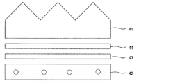
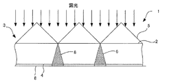
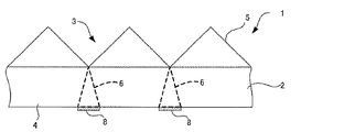
- FIG. 2 is a schematic cross-sectional view of a prism sheet A in which a positive photosensitive layer 8 is formed on a second surface 4 of a support 2.
- FIG. 3 is a schematic cross-sectional view showing a state in which a prism sheet A having a positive photosensitive layer 8 formed on a second surface 4 of a support 2 is exposed.
- FIG. 5 is a schematic cross-sectional view showing a state in which a white reflective sheet 40 is arranged on the support 2.
- FIG. FIG. 5 is a schematic cross-sectional view showing a state where a white reflective sheet 40 is peeled from the support 2. It is the graph which normalized the relationship between luminous intensity and an outgoing angle on the basis of luminous intensity (cd) measured in front (0 degree) about each prism sheet.
- Re ( ⁇ ) and Rth ( ⁇ ) represent in-plane retardation (unit: nm) and retardation in the thickness direction (unit: nm), respectively, at wavelength ⁇ .
- Re ( ⁇ ) is measured by making light having a wavelength of ⁇ nm incident in the normal direction of the film in KOBRA 21ADH or WR (manufactured by Oji Scientific Instruments). In selecting the measurement wavelength ⁇ nm, the wavelength selection filter can be exchanged manually, or the measurement value can be converted by a program or the like.
- Rth ( ⁇ ) is calculated by the following method.
- Rth ( ⁇ ) is Re ( ⁇ ), with the in-plane slow axis (determined by KOBRA 21ADH or WR) as the tilt axis (rotation axis) (in the absence of the slow axis, any in-plane value)
- the light is incident at a wavelength of ⁇ nm from the inclined direction in steps of 10 degrees from the normal direction to 50 degrees on one side with respect to the film normal direction of the rotation axis of KOBRA 21ADH or WR is calculated based on the measured retardation value, the assumed average refractive index, and the input film thickness value.
- Re ( ⁇ ) represents a retardation value in a direction inclined by an angle ⁇ from the normal direction.
- nx represents the refractive index in the slow axis direction in the plane
- ny represents the refractive index in the direction perpendicular to nx
- nz represents the refractive index in the direction perpendicular to nx and ny.
- d represents the film thickness of the film.
- Rth ( ⁇ ) is calculated by the following method.
- Rth ( ⁇ ) is from ⁇ 50 degrees to +50 degrees with respect to the normal direction of the film, with Re ( ⁇ ) being the in-plane slow axis (determined by KOBRA 21ADH or WR) and the tilt axis (rotating axis).
- the light of wavelength ⁇ nm is incident from each inclined direction in 10 degree steps and measured at 11 points. Based on the measured retardation value, the assumed average refractive index, and the input film thickness value, KOBRA 21ADH or WR is calculated.
- the assumed value of the average refractive index may be a value in a polymer handbook (John Wiley & Sons, Inc.) or a catalog of various optical films. Those whose average refractive index is not known can be measured with an Abbe refractometer. Examples of the average refractive index values of main optical films are given below: Cellulose acylate (1.48), cycloolefin polymer (1.52), polycarbonate (1.59), polymethyl methacrylate (1.49), and polystyrene (1.59).
- the measurement wavelength is not particularly described for Re, Rth, and refractive index, it is assumed that the measurement wavelength is 550 nm. Moreover, when there is no description about a measurement environment especially, it shall be the value measured in the environment of temperature 25 degreeC relative humidity 60% RH.
- the “slow axis” means a direction in which the refractive index is maximized.
- the “back side” refers to the side opposite to the screen viewing side, usually the backlight side.
- numerical ranges and numerical values should be interpreted as numerical ranges and numerical values including errors allowed in the technical field to which the present invention belongs.
- the relationship between the optical axes includes an error allowed in the technical field to which the present invention belongs.
- the angles in this specification are described with the lower side of the screen of the liquid crystal display device being 0 ° and the counterclockwise direction being positive when the liquid crystal display device is viewed from the normal direction of the screen.
- parallel and orthogonal mean that the angle is within a range of strict angle ⁇ 5 ° or less.
- the error from the exact angle is preferably less than ⁇ 4 °, and more preferably less than ⁇ 3 °.
- FIG. 1 shows a schematic cross-sectional view of an example of the liquid crystal display device of the present invention.
- the liquid crystal display device 1 shown in FIG. 1 includes a TN mode liquid crystal cell 10, a viewing side polarizing film 12 and a backlight side polarizing film 14 on each side, and a viewing side polarizing film 12 and a backlight side polarizing film 14.
- Retardation films 16 and 18 are provided between the mode liquid crystal cell 10 and protective films 20 and 22 are provided on the outer sides of the viewing-side polarizing film 12 and the backlight-side polarizing film 14, respectively.
- FIG. 2 shows an example of the O mode arrangement.
- the rubbing directions 10a and 10b applied to the inner surfaces of a pair of substrates (not shown) of the liquid crystal cell 10 and the transmission axes 12a and 14a of the polarizing films 12 and 14 arranged closer to each other Are orthogonal to each other.
- E mode it arrange
- the E-mode is preferred. By adopting the E-mode, an effect that variation in front contrast is small can be obtained.
- the first polarizing film and the second polarizing film are opposed to each other between the first polarizing film and the second polarizing film.
- the twisted alignment mode liquid crystal cell, the first retardation film disposed between the first polarizing film and the liquid crystal cell, and the second polarizing film disposed between the liquid crystal cell and the liquid crystal cell.
- a second retardation film A liquid crystal display device having a backlight unit including a condensing prism sheet on the back side of the liquid crystal cell, wherein the first polarizing film and the second polarizing film have absorption axes orthogonal to each other,
- the liquid crystal cell includes a first substrate and a second substrate that are provided closer to each of the first polarizing film and the second polarizing film, and at least one of the first substrate and the second substrate.
- Has a transparent electrode the transmission axis of the first polarizing film is parallel to the rubbing direction of the first substrate, and the transmission axis of the second polarizing film is parallel to the rubbing direction of the second substrate.
- the in-plane retardation Re (550) at a wavelength of 550 nm and the retardation Rth (550) in the thickness direction at a wavelength of 550 nm are respectively represented by the following formula (I) and Satisfying formula (II), 1 nm ⁇ Re (550) ⁇ 50 nm (I) 120 nm ⁇ Rth (550) ⁇ 220 nm (II)
- the Depolarizing Index (DI value) of the liquid crystal cell is 0.000800 or less, and when the amount of backlight light emitted from the backlight unit is measured, the normal line of the display screen of the liquid crystal display device is The average value of the light amount in the range of the emission angle of 50 ° to 85 ° tilted in the direction in which the in-plane phase difference of the liquid crystal cell is maximized is 12% or less with respect to the light amount in the normal direction
- DI value Depolarizing Index
- a liquid crystal display device includes a first polarizing film, a second polarizing film, and a twisted alignment disposed so as to face each other between the first polarizing film and the second polarizing film.
- the liquid crystal cell has a first substrate and a second substrate provided closer to each of the first polarizing film and the second polarizing film, and the first substrate and the second substrate At least one of them has a transparent electrode, the transmission axis of the first polarizing film, and the rabbi of the first substrate.
- the transmission direction of the second polarizing film and the rubbing direction of the second substrate are orthogonal, and the first retardation film and the second retardation film are surfaces at a wavelength of 550 nm, respectively.
- the inner retardation Re (550) and the retardation Rth (550) in the thickness direction at a wavelength of 550 nm satisfy the following formulas (III) and (IV): 60 nm ⁇ Re (550) ⁇ 120 nm (III) 120 nm ⁇ Rth (550) ⁇ 220 nm (IV)
- DI value The Depolarizing Index (DI value) of the liquid crystal cell is 0.000800 or less, and when the amount of backlight light emitted from the backlight unit is measured, the normal line of the display screen of the liquid crystal display device is The average value of the light amount in the range of the emission angle of 50 ° to 85 ° tilted in the direction in which the in-plane phase difference of the liquid crystal cell is maximized is 12% or less with respect to the light amount in the normal direction And
- the first embodiment is the E-mode, and the retardation of the retardation film included in the liquid crystal display device satisfies the formulas (I) and (II).
- the second embodiment is an O-mode, and the retardation of the retardation film included in the liquid crystal display device satisfies the formulas (III) and (IV). Details of these will be described below.
- the in-plane retardation Re (1) of the first and second retardation films at a wavelength of 550 nm is used.
- 550) and retardation Rth (550) in the thickness direction at a wavelength of 550 nm satisfy both the following formula (I) and the following formula (II).
- Re (550) When Re (550) is less than 1 nm, the slow axis range described later is too large, and unevenness tends to occur on the black display screen.
- the lower limit of Re (550) is preferably 2 nm, most preferably 3 nm, and the upper limit of Re (550) is preferably 20 nm, and most preferably 10 nm.
- the lower limit value of Rth (550) is preferably 130 nm, most preferably 150 nm, and the upper limit value of Rth (550) is preferably 200 nm.
- the in-plane slow axis of the retardation film used in the first embodiment is preferably parallel to the transmission axis of the polarizing film when Re (550) is in the range of 30 to 50 nm.
- Re (550) is in the range of 30 to 50 nm.
- it is preferably perpendicular to the transmission axis of the polarizing film, and the other range may be either parallel or perpendicular to the transmission axis of the polarizing film.
- Such a retardation film may be produced by biaxially stretching a specific polymer film, or may be produced by adding a retardation increasing agent. Details of these will be described later.
- the in-plane slow axis of the retardation film used in the first embodiment is shifted by an angle ⁇ within a range of 1 ° to 10 ° from parallel or orthogonal to the transmission axis of the polarizing film. Therefore, it is possible to cancel the phase difference remaining in the cell during black display, which is characteristic of the TN mode liquid crystal, and as a result, the front contrast is improved.
- the larger the in-plane retardation of the retardation film the smaller the angle ⁇ needs to be set.
- the angle ⁇ needs to be set to at least twice the slow axis range.
- the angle of the in-plane slow axis of the retardation film can be controlled by oblique stretching or the like, and a roll-type polarizing plate can be produced from a roll-type retardation film.
- the P value which is the product of the slow axis range and Re (550), is preferably 20 or less, more preferably 15 or less. The following are most preferred. By setting it as such a range, it exists in the tendency for the effect of this invention to be exhibited more effectively.
- the lower limit is not particularly defined, and P> 0.
- P Slow axis range x Re (550)
- the slow axis range is the difference between the maximum value and the minimum value of the in-plane slow axis (unit: °) of the retardation film.
- the slow axis range is defined as the difference between the maximum value and the minimum value of the in-plane slow axis orientation (unit: °) of the retardation film, and the slow axis range of the retardation film is preferably small.
- the slow axis range depends on the material of the retardation film and the manufacturing method such as the stretching method, but it also depends on the in-plane retardation, and the smaller the in-plane retardation, the larger the slow axis range becomes.
- the slow axis range in the first embodiment of the present invention is preferably 2.0 ° or less, and more preferably 1.0 ° or less. By setting it as such a range, the effect that the variation in front contrast is small is acquired. The details of the method for measuring the slow axis range of the retardation film are described in the Examples section.
- the total haze value of the retardation films 16 and 18 in the first embodiment is preferably 1.0% or less, more preferably 0.60% or less, still more preferably 0.30% or less, and most preferably 0.20%.
- the internal haze value is preferably 0.50% or less, more preferably 0.30% or less, and most preferably 0.10% or less.
- the thickness of the retardation film in the first embodiment is not particularly limited, but in general, it is preferably 10 to 100 ⁇ m, and more preferably 20 to 50 ⁇ m.
- the first retardation film and the second retardation film have an in-plane retardation Re (550 at a wavelength of 550 nm. ) And retardation Rth (550) in the thickness direction at a wavelength of 550 nm satisfy the following formulas (III) and (IV): 60 nm ⁇ Re (550) ⁇ 120 nm (III) 120 nm ⁇ Rth (550) ⁇ 220 nm (IV) By setting it as such a range, it becomes possible to improve the optical compensation of the left-right direction.
- Re is preferably 85 nm ⁇ Re (550) ⁇ 110.
- Rth is preferably 130 nm ⁇ Rth (550) ⁇ 150.
- the in-plane slow axis of the retardation film used in the second embodiment is preferably parallel to the transmission axis of the polarizing film.
- a retardation film may be produced by biaxially stretching a specific polymer film, or may be produced by adding a retardation increasing agent. Details of these will be described later.
- the retardation film used in the second embodiment of the present invention preferably has a P value that is the product of the slow axis range and Re (550) of 40 or less. By setting it as such a range, it exists in the tendency for the effect of this invention to be exhibited more effectively.
- the lower limit is not particularly defined, and P> 0.
- the slow axis range in the second embodiment of the present invention is preferably 0.5 ° or less, and preferably 0.4 ° or less. By setting it as such a range, the effect that the variation in front contrast is small is acquired.
- the total haze value of the retardation films 16 and 18 in the second embodiment is preferably 1.0% or less, more preferably 0.60% or less, still more preferably 0.30% or less, and most preferably 0.20%.
- the internal haze value is preferably 0.50% or less, more preferably 0.30% or less, and most preferably 0.10% or less.
- the thickness of the retardation film in the second embodiment is not particularly limited, but is generally preferably 10 to 100 ⁇ m.
- Such a retardation film can be prepared by using a norbornene film or the like.
- the desired retardation may be expressed by stretching (biaxial stretching), or may be expressed by a retardation increasing agent or the like.
- the polymer material forming the retardation film used in the present invention is not particularly limited.
- Acrylic polymers such as polypolymers and polymethyl methacrylate
- styrenic polymers such as polystyrene and acrylonitrile / styrene copolymers (AS resin) can be used.
- Polyolefin such as polyethylene and polypropylene, cyclopolyolefin such as norbornene, polyolefin polymer such as ethylene / propylene copolymer, vinyl chloride polymer, amide polymer such as nylon and aromatic polyamide, imide polymer, sulfone polymer , Polyether sulfone polymer, polyether ether ketone polymer, polyphenylene sulfide polymer, vinylidene chloride polymer, vinyl alcohol polymer, vinyl butyral polymer, arylate polymer, polyoxymethylene polymer, epoxy polymer, or the above
- One or two or more kinds of polymers can be selected from polymers mixed with the polymer, and used as a main component to produce and use a polymer film. Commercially available polymer films that are widely used can also be used.
- the first embodiment preferably uses a cellulose acylate film or a norbornene film.
- cellulose acylate film is used. It is particularly preferable to use a rate film.
- the second embodiment preferably uses a norbornene film.
- the cellulose acylate film and the norbornene film will be described.
- Cellulose acylate film (cellulose acylate)
- Cellulose acylate raw material cellulose used in the present invention includes cotton linter, wood pulp (hardwood pulp, conifer pulp), etc., and any cellulose acylate obtained from any raw material cellulose can be used. May be used. Detailed descriptions of these raw material celluloses can be found in, for example, Marusawa and Uda, “Plastic Materials Course (17) Fibrous Resin”, published by Nikkan Kogyo Shimbun (published in 1970), and the Japan Institute of Invention and Innovation Technical Bulletin No. 2001. The cellulose described in No. -1745 (pages 7 to 8) can be used, and the cellulose acylate laminated film in the present invention is not particularly limited.
- the cellulose acylate preferably used in the present invention will be described in detail.
- the ⁇ -1,4-bonded glucose unit constituting cellulose has free hydroxyl groups at the 2nd, 3rd and 6th positions.
- Cellulose acylate is a polymer obtained by acylating part or all of these hydroxyl groups with an acyl group.
- the degree of acyl substitution means the sum of the ratios of acylation of the hydroxyl groups of cellulose located at the 2-position, 3-position and 6-position (100% acylation at each position is substitution degree 1).
- acyl group of cellulose acylate in the present invention may be an aliphatic group or an allyl group and is not particularly limited. These are, for example, cellulose alkylcarbonyl esters, alkenylcarbonyl esters, aromatic carbonyl esters, aromatic alkylcarbonyl esters, and the like, each of which may further have a substituted group.
- Preferred examples of these include acetyl group, propionyl group, butanoyl group, heptanoyl group, hexanoyl group, octanoyl group, decanoyl group, dodecanoyl group, tridecanoyl group, tetradecanoyl group, hexadecanoyl group, octadecanoyl group, isobutanoyl group Group, tert-butanoyl group, cyclohexanecarbonyl group, oleoyl group, benzoyl group, naphthylcarbonyl group, cinnamoyl group and the like.
- an acetyl group, a propionyl group, a butanoyl group, a dodecanoyl group, an octadecanoyl group, a tert-butanoyl group, an oleoyl group, a benzoyl group, a naphthylcarbonyl group, a cinnamoyl group, and the like are more preferable, and an acetyl group is particularly preferable.
- a propionyl group and a butanoyl group (when the acyl group has 2 to 4 carbon atoms) are preferred, and an acetyl group (when the cellulose acylate is cellulose acetate) is more preferred.
- examples of the cellulose acylate include triacetyl cellulose (TAC), diacetyl cellulose (DAC), cellulose acetate propionate (CAP), cellulose acetate butyrate (CAB), and cellulose acetate phthalate.
- TAC triacetyl cellulose
- DAC diacetyl cellulose
- CAP cellulose acetate propionate
- CAB cellulose acetate butyrate
- cellulose acetate phthalate examples of the cellulose acylate film used in the present invention, it is preferable from the viewpoint of retardation development and cost that all the acyl groups of the cellulose acylate are acetyl groups.
- the acyl substitution degree of the cellulose acylate preferably satisfies 2.0 to 2.9 from the viewpoint of optical expression.
- the acyl substitution degree of the cellulose acylate is more preferably 2.1 to 2.89, and particularly preferably 2.4 to 2.86.
- the substitution degree of the acyl group having 3 or more carbon atoms preferably satisfies 0.3 to 1.0, and 0.4 to 0.9 Is more preferable, and 0.5 to 0.8 is particularly preferable.
- the substitution degree of the acyl group can be measured according to the method prescribed in ASTM-D817-96. The portion not substituted with an acyl group usually exists as a hydroxyl group.
- cellulose acylates can be synthesized by a known method, for example, by the method described in JP-A-10-45804.
- an organic acid such as acetic acid or methylene chloride is used as an organic solvent as a reaction solvent.
- the catalyst when the acylating agent is an acid anhydride, a protic catalyst such as sulfuric acid is preferably used, and when the acylating agent is an acid chloride (for example, CH 3 CH 2 COCl), Basic compounds are used.
- cellulose mixed fatty acid ester The most common industrial synthesis method of cellulose mixed fatty acid ester is to use cellulose corresponding to fatty acid corresponding to acetyl group and other acyl groups (acetic acid, propionic acid, valeric acid, etc.) or their acid anhydrides. This is a method of acylating with a mixed organic acid component.
- the cellulose acylate preferably has a number average molecular weight (Mn) of 40,000 to 200,000, more preferably 100,000 to 200,000.
- the cellulose acylate used in the present invention preferably has an Mw / Mn ratio of 4.0 or less, more preferably 1.4 to 2.3.
- the average molecular weight and molecular weight distribution of cellulose acylate and the like are calculated by calculating the number average molecular weight (Mn) and the weight average molecular weight (Mw) using gel permeation chromatography (GPC).
- GPC gel permeation chromatography
- additives for example, UV inhibitors, plasticizers, deterioration inhibitors, fine particles, optical property modifiers, etc.
- UV inhibitors for example, UV inhibitors, plasticizers, deterioration inhibitors, fine particles, optical property modifiers, etc.
- the cellulose acylate film used in the present invention preferably contains at least one of a sugar ester compound and a polycondensed ester from the viewpoint of reducing the internal haze of the film.
- the sugar ester compound is a compound in which at least one substitutable group (for example, hydroxyl group, carboxyl group) in the monosaccharide or polysaccharide constituting the compound and at least one substituent group are ester-bonded.
- the sugar ester compound referred to here includes a wide range of sugar derivatives, for example, a compound containing a sugar residue such as gluconic acid as a structure. That is, the sugar ester compound includes an ester of glucose and carboxylic acid and an ester of gluconic acid and alcohol.
- the substitutable group in the monosaccharide or polysaccharide constituting the sugar ester compound is preferably a hydroxyl group.
- the sugar ester compound includes a structure derived from a monosaccharide or a polysaccharide constituting the sugar ester compound (hereinafter also referred to as a sugar residue).
- the structure of the sugar residue per monosaccharide is referred to as the structural unit of the sugar ester compound.
- the structural unit of the sugar ester compound preferably includes a pyranose structural unit or a furanose structural unit, and more preferably all sugar residues are a pyranose structural unit or a furanose structural unit. Further, when the sugar ester is composed of a polysaccharide, it preferably contains both a pyranose structural unit or a furanose structural unit.
- the sugar residue of the sugar ester compound may be derived from 5 monosaccharides or 6 monosaccharides, but is preferably derived from 6 monosaccharides.
- the number of structural units contained in the sugar ester compound is preferably 1 to 12, more preferably 1 to 6, and particularly preferably 1 or 2.
- the sugar ester compound is more preferably a sugar ester compound containing 1 to 12 pyranose structural units or furanose structural units in which at least one hydroxyl group is esterified, and at least one of the hydroxyl groups is an ester. More preferably, it is a sugar ester compound containing one or two pyranose structural units or furanose structural units.
- the sugar ester compound has a glucose skeleton or a sucrose skeleton, which is described as compound 5 in [0059] of JP-A-2009-1696 as a compound 5 and has a maltose skeleton used in Examples of the same document. Compared to an ester compound and the like, it is more preferable from the viewpoint of compatibility with a polymer.
- the sugar ester compound used in the present invention has a structure represented by the following general formula (1) including the substituent used.
- General formula (1) (OH) p -G- (L 1 -R 11 ) q (O-R 12 ) r
- G represents a sugar residue
- L 1 represents any one of —O—, —CO—, and —NR 13 —
- R 11 represents a hydrogen atom or a monovalent substituent.
- R 12 represents a monovalent substituent bonded by an ester bond.
- p, q, and r each independently represent an integer of 0 or more, and p + q + r is equal to the number of hydroxyl groups on the assumption that G is an unsubstituted saccharide having a cyclic acetal structure.
- the preferable range of G is the same as the preferable range of the sugar residue.
- L 1 is preferably —O— or —CO—, and more preferably —O—.
- L 1 is particularly preferably an linking group derived from an ether bond or an ester bond, and more preferably an linking group derived from an ester bond.
- L 1 s may be the same or different.
- At least one of R 11 and R 12 preferably has an aromatic ring.
- R 11 , R 12 and R 13 are substituted or unsubstituted.
- R 11 , R 12 and R 13 are substituted or unsubstituted.
- a substituted alkyl group or a substituted or unsubstituted aryl group is more preferable, and an unsubstituted acyl group, a substituted or unsubstituted alkyl group, or an unsubstituted aryl group is particularly preferable.
- R 11 , R 12 and R 13 they may be the same as or different from each other.
- the p represents an integer of 0 or more, and the preferred range is the same as the preferred range of the number of hydroxyl groups per monosaccharide unit described later, but in the present invention, the p is preferably zero.
- the r preferably represents a number larger than the number of pyranose structural units or furanose structural units contained in the G.
- Q is preferably 0.
- p + q + r is equal to the number of hydroxyl groups when G is assumed to be an unsubstituted saccharide having a cyclic acetal structure, the upper limit values of p, q, and r are uniquely determined according to the structure of G. Is done.
- the substituent of the sugar ester compound for example, the description in paragraph No. 0043 of JP2012-068611A can be referred to, and the contents thereof are incorporated in the present specification.
- an alkyl group or an acyl group is more preferable, a methyl group, an acetyl group, a benzoyl group, or a benzyl group is more preferable, and an acetyl group and a benzyl group are particularly preferable.
- the number of hydroxyl groups per structural unit in the sugar ester compound (hereinafter also referred to as hydroxyl group content) is preferably 3 or less, more preferably 1 or less, and zero. Particularly preferred.
- the sugar ester compound used in the film used in the present invention preferably has no unsubstituted hydroxyl group, and the substituent consists only of an acetyl group and / or a benzyl group. Further, as the ratio of the acetyl group to the benzyl group in the sugar ester compound, it is preferable that the ratio of the benzyl group is small to some extent because the change in blackness when incorporated in a liquid crystal display device becomes small. Specifically, the ratio of the benzyl group to the sum of all unsubstituted hydroxyl groups and all substituents in the sugar ester compound is preferably 60% or less, and preferably 40% or less.
- the sugar ester compound has a number average molecular weight of preferably 200 to 3500, more preferably 200 to 3000, and particularly preferably 250 to 2000.
- the sugar ester compound is preferably contained in an amount of 2 to 30% by mass, more preferably 5 to 20% by mass, based on the polymer (preferably cellulose acylate) contained in the film used in the present invention. It is particularly preferable to contain 15% by mass.
- the additive amount (parts by mass) of the sugar ester compound with respect to the additive amount (parts by mass) of the additive having a negative intrinsic birefringence Is preferably added 2 to 10 times (mass ratio), more preferably 3 to 8 times (mass ratio).
- the addition amount (parts by mass) of the sugar ester compound relative to the addition amount (parts by mass) of the polyester plasticizer is 2 to 10 times (mass). Ratio) is preferably added, more preferably 3 to 8 times (mass ratio).
- the said sugar ester compound may be used independently, or may use 2 or more types together.
- the polycondensed ester compound used in the present invention has a number average molecular weight of 300 or more and less than 2000 so as not to cause haze, bleed out or volatilize from the film. It is preferable to use a polycondensed ester compound plasticizer.
- the polycondensed ester compound is not particularly limited, but a polyester plasticizer having an aromatic ring or a cycloalkyl ring in the molecule can be preferably used.
- a polyester plasticizer having an aromatic ring or a cycloalkyl ring in the molecule can be preferably used.
- the optical film used in the present invention contains a nitrogen-containing compound plasticizer, an additive that can be added to a normal cellulose acylate film, or the like as an additive other than the sugar ester compound and the polycondensate ester. Can do.
- these additives include nitrogen-containing compound plasticizers; plasticizers other than the aforementioned sugar ester compounds, polycondensation esters and nitrogen-containing compound plasticizers; fine particles; retardation enhancers; negative addition of intrinsic birefringence
- compounds described in International Publication WO2008-126535 can also be preferably used.
- the optical film used in the present invention preferably contains a nitrogen-containing aromatic compound-based plasticizer.
- the nitrogen-containing aromatic compound-based plasticizer has any one of pyridine, pyrimidine, triazine, and purine as a mother nucleus, and an alkyl group, an alkenyl group, an alkynyl group, an amino group at any substitutable position of the mother nucleus, An amide group (meaning a structure in which any acyl group is bonded via an amide bond), an aryl group, an alkoxy group, a thioalkoxy group, an alkyl or an arylthio group (an alkyl group or an aryl group via a sulfur atom) Or a group having a heterocyclic group as a substituent.
- the substituent of the mother nucleus of these nitrogen-containing aromatic compound plasticizers may be further substituted with another substituent, and the other substituent is not particularly limited.
- the amino group may be an alkyl group (further, the alkyl groups may be linked to form a ring) or —SO 2 R ′ (R ′ is an arbitrary group).
- R ′ is an arbitrary group.
- the nitrogen-containing aromatic compound used in the present invention is preferably contained in an amount of 1 to 40% by mass, more preferably 1 to 15% by mass, and more preferably 2 to 5% by mass with respect to cellulose acylate. Particularly preferred.
- nitrogen-containing aromatic compound plasticizer examples include compounds described in paragraph numbers 0082 to 0101 of JP2012-068611A, and these compounds are incorporated in the present specification.
- Plasticizers other than the sugar ester compound, polycondensation ester and nitrogen-containing compound plasticizer The film used in the present invention has other plasticizers other than the sugar ester compound, polycondensation ester and nitrogen-containing compound plasticizer.
- the other plasticizers include phosphate ester plasticizers, trimellitic acid ester plasticizers, pyromellitic acid plasticizers, glycolate plasticizers, citrate ester plasticizers, and carboxylic acid ester plasticizers.
- An agent, an acrylic polymer or the like can be preferably used.
- phosphate ester plasticizer examples include triphenyl phosphate (TPP), tricresyl phosphate (TCP), cresyl diphenyl phosphate, octyl diphenyl phosphate, biphenyl diphenyl phosphate (BDP), trioctyl phosphate, tributyl phosphate and the like;
- acid ester plasticizer examples include dimethyl phthalate (DMP), diethyl phthalate (DEP), dibutyl phthalate (DBP), dioctyl phthalate (DOP), diphenyl phthalate (DPP), diethyl hexyl phthalate (DEHP), O-acetyl citrate.
- Acid triethyl OACTE
- O-acetyl tributyl citrate OACTB
- acetyl triethyl citrate acetyl tributyl citrate
- oleic acid Le methyl acetyl ricinoleate
- dibutyl sebacate triacetin, tributyrin, butyl phthalyl butyl glycolate, ethyl phthalyl ethyl glycolate, methyl phthalyl ethyl glycolate, and butyl phthalyl butyl glycolate and the like.
- it is preferable to use a phosphate ester type plasticizer it is preferable to use a phosphate ester type plasticizer, and TPP and BDP are more preferable.
- These plasticizers may be used in combination of two or more.
- Fine particles As fine particles that may be added to the optical film used in the present invention, as examples of inorganic compounds, silicon dioxide, titanium dioxide, aluminum oxide, zirconium oxide, calcium carbonate, talc, clay, calcined kaolin, calcined Mention may be made of calcium silicate, hydrated calcium silicate, aluminum silicate, magnesium silicate and calcium phosphate. Fine particles containing silicon are preferable in terms of low haze, and silicon dioxide is particularly preferable.
- the average primary particle size of the fine particles is preferably 5 to 50 nm, and more preferably 7 to 20 nm. These are preferably contained mainly as secondary aggregates having a particle size of 0.05 to 0.3 ⁇ m.
- Silicon dioxide fine particles are commercially available, for example, under the trade names Aerosil R972, R972V, R974, R812, 200, 200V, 300, R202, OX50, TT600, NAX50 (Nippon Aerosil Co., Ltd.). be able to.
- Zirconium oxide fine particles are commercially available under the trade names of Aerosil R976 and R811 (manufactured by Nippon Aerosil Co., Ltd.) and can be used.
- the polymer include silicone resin, fluororesin, and acrylic resin. Silicone resins are preferable, and those having a three-dimensional network structure are particularly preferable.
- Tospearl 103, 105, 108, 120, 145, 3120, and 240 (manufactured by Toshiba Silicone Co., Ltd.) It is marketed by name and can be used.
- Aerosil 200V and Aerosil R972V are particularly preferably used because they have a large effect of reducing the friction coefficient while keeping the haze of the cellulose derivative film low.
- the content of these fine particles with respect to the polymer (preferably cellulose acylate) in the film used in the present invention is preferably 0.05 to 1% by mass, particularly preferably 0.1 to 0.5% by mass.
- the optical film used in the present invention can be formed using a solution casting film forming method.
- the method for producing a film used in the present invention preferably includes a step of forming a film containing cellulose acylate as the polymer by solution casting.
- the solution casting film forming method is used as an example of the film manufacturing method used in the present invention, the film manufacturing method is not limited to the solution casting film forming method.
- a well-known method can be used.
- Dissolution step A step of dissolving the cellulose acylate and additives in an organic solvent mainly containing a good solvent for cellulose acylate while stirring to form a dope, or an additive in a cellulose acylate solution This is a step of mixing a solution to form a dope.
- a method carried out at normal pressure a method carried out below the boiling point of the main solvent, a method carried out under pressure above the boiling point of the main solvent, JP-A-9-95544 and JP-A-9-95557.
- various dissolution methods such as a method using a cooling dissolution method as described in JP-A-9-95538 and a method using a high pressure as described in JP-A-11-21379 can be used.
- the method of pressurizing at a boiling point or higher is preferred.
- the concentration of cellulose acylate in the dope is preferably 10 to 35% by mass.
- An additive is added to the dope during or after dissolution to dissolve and disperse, then filtered through a filter medium, defoamed, and sent to the next step with a liquid feed pump.
- the viscosity of the polymer solution discharged from the discharge device is a vibration viscosity ⁇ (unit: Pa ⁇ s) measured at 25 ° C. and 1 Hz of the polymer solution, represented by the following formula (14): It controls to satisfy
- vibration viscosity (eta) By setting it as such vibration viscosity (eta), a film can be film-formed so that predetermined conditions may be satisfy
- the viscosity of the polymer solution discharged from the discharge device is a vibration viscosity ⁇ (unit: Pa ⁇ s) measured at 25 ° C. and 1 Hz of the polymer solution, represented by the following formula (17): It is preferable to control so as to satisfy.
- Expression (17) 30 Pa ⁇ s ⁇ ⁇ 200 Pa ⁇ s
- the viscosity of the polymer solution is more preferably 40 Pa ⁇ s ⁇ ⁇ 200 Pa ⁇ s, and particularly preferably 40 Pa ⁇ s ⁇ ⁇ 100 Pa ⁇ s.
- the casting process is a process of casting a polymer solution onto a support traveling from a discharge device.
- the dope is fed to a pressure die through a liquid feed pump (for example, a pressurized metering gear pump) and transferred to an endless metal belt such as an endless metal belt such as a stainless steel belt or a rotating metal drum.
- a step of casting a dope from a pressure die slit at a casting position on the body can be mentioned.
- the suction step is a step of sucking a bead portion of the cast polymer solution from the upstream side in the running direction of the support by a suction device until the polymer solution reaches the support.
- the molding step is a step in which the polymer solution that has reached the support is conveyed at a casting speed of 15 to 80 m / min and molded into a film. Further, in the casting process, the suction process and the molding process, it is preferable that the film production method used in the present invention is controlled so as to satisfy the formula (14).
- the solution film forming apparatus is mainly composed of a casting die (corresponding to a discharge device), a casting band (corresponding to a traveling support), and a decompression chamber (corresponding to a suction device).
- the casting die is disposed opposite the casting band at the position of the casting drum.
- a dope containing a polymer material such as cellulose triacetate is extruded from the tip of the casting die into a film.
- the extruded dope is temporarily attached to the surface of the traveling casting band and is transported.
- the distance h k (unit: mm) between the discharge device and the support preferably satisfies the following formula (13). Expression (13) 0.25 mm ⁇ h k
- the distance h k (unit: mm) between the discharge device and the support preferably satisfies the following formula (18). Equation (18) 0.3mm ⁇ h k ⁇ 1.5mm
- the h k is more preferably 0.5 to 1.2 mm.
- the discharge unit clearance of the discharge device is controlled so as to satisfy the following formula (11).
- Formula (11) 1.0 ⁇ 10 6 / min ⁇ (casting speed ⁇ unstretched dry film thickness) / (discharge portion clearance) ⁇ 1.0 ⁇ 10 7 / min (11 ′)
- Unstretched dry film thickness Film thickness after stretching ⁇ ⁇ 1+ (stretching ratio in film transport direction (%)) / 100 ⁇ ⁇ ⁇ 1+ (stretching ratio in direction orthogonal to film transport direction (%)) / 100 ⁇
- the discharge section clearance represents the lip clearance (unit: m) of the discharge device
- the casting speed represents the running speed (unit: m / min) of the support.)
- the lower limit of the value of (casting speed ⁇ unstretched dry film thickness) / (discharge portion clearance) in formula (11) is preferably 1.1 ⁇ 10 6 / min or more, and 1.2 ⁇ More preferably, it is 10 6 / min or more.
- the upper limit value is preferably 9.0 ⁇ 10 6 / min or less, and more preferably 6.0 ⁇ 10 6 / min or less.
- the discharge device is preferably a so-called die, and is preferably a pressure die that can adjust the slit shape of the die portion of the die and easily make the film thickness uniform.
- the pressure die includes a coat hanger die and a T die, and any of them is preferably used.
- two or more pressure dies may be provided on the metal support, and the dope amount may be divided and stacked. Or it is also preferable to obtain the film of a laminated structure by the co-casting method which casts several dope simultaneously.
- the unstretched dry film thickness of the film may be adjusted so as to satisfy the above formula (11), and the solid content concentration contained in the dope, the slit gap of the die die, The extrusion pressure from the die, the metal support speed, etc. may be adjusted.
- the casting band is preferably formed endlessly and is wound between the casting drum and the driving drum.
- the casting drum preferably travels around the driving drum and the casting drum by rotating the driving drum.
- the traveling speed of the traveling support is transported at a casting speed of 15 to 80 m / min. Moreover, it is necessary to control the casting speed so as to satisfy the formula (11).
- the casting speed is preferably 15 to 55 m / min, and more preferably 30 to 55 m / min.
- the decompression chamber is provided on the upstream side of the casting die with respect to the traveling direction of the casting band, and is connected to the blower via a suction duct.
- the inside of the decompression chamber becomes negative pressure, and the suction force is applied to the surface of the dope casting portion of the gap between the casting die and the casting band that is temporarily attached to the casting band. Is granted. Thereby, even if the casting band is run at a high speed, the dope casting portion can be stabilized.
- the film production method used in the present invention is characterized in that the suction step is controlled to satisfy the following formula (12).
- the suction pressure to the bead represents the pressure applied from the suction device to the bead
- the pressure in the direction in which the bead is attracted to the suction device side is represented by a negative value
- the suction device side Pressure in the direction of being pushed out is expressed as a positive value.
- the bead portion can be deformed by performing suction so as to satisfy the above formula (12) and controlling so as to satisfy the above-described condition.
- the suction pressure to the bead is preferably ⁇ 900 Pa ⁇ suction pressure to the bead ⁇ 300 Pa, more preferably ⁇ 800 Pa ⁇ suction pressure to the bead ⁇ 350 Pa.
- a suction tank between the decompression chamber and the blower is preferably provided with a buffer tank having a capacity 10 to 100 times that of the decompression chamber to prevent vibration from being transmitted to the decompression chamber.
- the optical film of the present invention can be produced by any casting of 15 to 80 m / min. That is, an optical film having a thin film of 20 to 60 ⁇ m, improved uniformity of film thickness, and suppressed fluctuations in the in-plane retardation accompanying changes in environmental humidity can be produced. It can be produced by any casting at 15 to 80 m / min. In the case of producing a conventional 80 ⁇ m thick film, stable high-speed casting at 50 m / min or more is possible.
- Solvent evaporation step The web (before the cellulose acylate film is completed, which still contains a lot of solvent) is heated on the support so that the web can be peeled from the support. It is preferable to include a step of evaporating the solvent until The dope on the casting band evaporates and dries while the casting band travels for one round, and a predetermined self-supporting property is obtained. And the strip
- the film production method used in the present invention includes a step of peeling the film from the support by controlling the temperature of the peeling portion of the support to be 0 ° C. or higher.
- the peeled web is sent to the next process.
- the residual solvent amount (the following formula) of the web at the time of peeling is too large, peeling is difficult, or conversely, if the film is peeled off after being sufficiently dried on the metal support, a part of the web is in the middle. It may come off.
- gel casting as a method for increasing the film forming speed as a conventional manufacturing method (the film forming speed can be increased by peeling while the amount of residual solvent is as large as possible).
- a gel casting method as a method for increasing the film forming speed as a conventional manufacturing method (the film forming speed can be increased by peeling while the amount of residual solvent is as large as possible).
- a poor solvent for cellulose acylate is added to the dope and the dope is cast and then gelled
- the temperature of the metal support is lowered and gelled. It is known that gelation can be performed on a metal support to increase the film strength at the time of peeling, thereby speeding up the peeling and increasing the film forming speed.
- the present inventors have found that the optical film obtained by gelation by such a conventional production method and increasing the film forming speed (that is, the casting speed) has poor film thickness uniformity. . That is, the method for producing a film used in the present invention is characterized in that the temperature of the peeling portion of the support is controlled within the above range to peel without gelation. In the method for producing a film used in the present invention, the temperature of the peeling portion of the support is preferably 10 ° C. or higher, more preferably 10 to 30 ° C.
- the amount of residual solvent at the time of peeling of the web on the support is preferably 5 to 150% by weight depending on the strength of drying conditions, the length of the support, etc., but when the amount of residual solvent is larger In the case of peeling, the amount of residual solvent at the time of peeling is determined in consideration of the economic speed and quality.
- the residual solvent amount of the web at the peeling position is preferably 10 to 150% by mass, and more preferably 10 to 120% by mass.
- M is the mass of the web at an arbitrary point in time
- N is the mass when the mass M is dried at 110 ° C. for 3 hours.
- the stretching temperature is not particularly limited as long as it is not contrary to the gist of the present invention.
- the stretching step is more preferably performed at a temperature of Tg-5 ° C. or lower in a state where the cellulose acylate film has never been heated to Tg-5 ° C. or higher.
- the web is dried by using a drying device that alternately conveys the web through rolls arranged in a drying device and / or a tenter device that clips and conveys both ends of the web with a clip. Is preferred.
- the web may or may not be heat-treated before stretching, but when the heat treatment is performed, the glass transition temperature of the cellulose acylate film is Tg. It is preferable not to heat the glass to Tg ⁇ 5 ° C. or higher.
- hot air is generally blown on both sides of the web, but there is also a means of heating by applying a microwave instead of the wind.
- the temperature, air volume, and time vary depending on the solvent used, and the conditions may be appropriately selected according to the type and combination of the solvents used.
- the cellulose acylate film may be stretched in any direction of a film transport direction (hereinafter also referred to as a longitudinal direction) and a direction orthogonal to the film transport direction (hereinafter also referred to as a lateral direction). . More preferably, it is biaxially stretched in the longitudinal and transverse directions. Stretching may be performed in one stage or in multiple stages.
- the total of the draw ratio in the film transport direction and the stretch ratio in the direction perpendicular to the film transport direction is 5% to 50%. Preferably, it is 10 to 40%.
- the stretching ratio in stretching in the cellulose acylate film conveying direction is preferably 0.1 to 10%. It is more preferably 0.1 to 8%, and particularly preferably 0.5 to 5%.
- the stretch ratio (elongation) of the cellulose acylate web during the stretching can be achieved by the difference in peripheral speed between the metal support speed and the stripping speed (stripping roll draw).
- the cellulose acylate film is preferably stretched in the transport direction (longitudinal direction) by increasing the rotational speed of the nip roll on the outlet side rather than the rotational speed of the nip roll on the inlet side.
- Stretch ratio (%) 100 ⁇ ⁇ (Length after stretching) ⁇ (Length before stretching) ⁇ / Length before stretching
- the stretching ratio in stretching in the direction (lateral direction) perpendicular to the cellulose acylate film conveying direction is preferably 3% or more. 5% or more is preferable. As an upper limit, it is preferable that it is 40% or less, and it is more preferable that it is 35% or less. In the present invention, it is preferable to stretch using a tenter device as a method of stretching in a direction perpendicular to the film conveying direction.
- norbornene film used in the present invention includes, for example, a ring-opening polymer hydrogenated product of a norbornene monomer, an addition polymer of a norbornene monomer and an olefin, an addition polymer of norbornene monomers, and derivatives thereof. Can be mentioned. Moreover, only 1 type may be used for norbornene-type resin, and 2 or more types may be used together.
- norbornene-based monomer examples include bicyclo [2.2.1] hept-2-ene (norbornene), 6-methylbicyclo [2.2.1] hept-2-ene, and 5,6-dimethylbicyclo.
- norbornene derivatives thereof examples include bicyclo [2.2.1] hept-2-ene (norbornene), 6-methylbicyclo [2.2.1] hept-2-ene, and 5,6-dimethylbicyclo.
- the ring-opening polymer hydrogenated product of the norbornene-based monomer those obtained by subjecting the norbornene-based monomer to ring-opening polymerization by a known method and then hydrogenating the remaining double bond can be widely used.
- the ring-opening polymer hydrogenated product may be a norbornene monomer homopolymer or a copolymer of a norbornene monomer and another cyclic olefin monomer.
- Examples of the addition polymer of norbornene monomer and olefin include a copolymer of norbornene monomer and ⁇ -olefin.
- the ⁇ -olefin is not particularly limited.
- the ⁇ -olefin having 2 to 20 carbon atoms, preferably 2 to 10 carbon atoms, specifically, ethylene, propylene, 1-butene, 3-methyl-1-butene.
- Examples of the norbornene-based resin include known ones, and are commercially available. Examples of known norbornene resins include those described in JP-A-1-240517. Examples of norbornene-based resins that can be obtained commercially include, for example, JSR Co., Ltd., trade name “Arton” series, Nippon Zeon Co., Ltd., trade name “Zeonor” series, and the like. Furthermore, a copolymer (COC) of a cyclic olefin and another olefin can also be preferably used, and examples thereof include TOPAS manufactured by Topas Advanced Polymers GmbH.
- COC copolymer
- a saturated norbornene resin having the following structure can be used for the film of the present invention.
- the saturated norbornene resin the compounds described in paragraph numbers 0044 to 0066 of JP-A-2007-328327 can also be employed, the contents of which are incorporated herein.
- the norbornene film can be preferably produced by melt film formation.
- the melt film formation is performed by obtaining steps such as drying of pellets, melt extrusion of resin, filtration, extrusion from a die, casting, and winding. Furthermore, it may be supplied to the die via a gear pump after filtration. Details of these can be referred to the descriptions in paragraph numbers 0113 to 0129 of JP-A-2007-328327, the contents of which are incorporated herein.
- the norbornene film is used as a retardation film having a predetermined optical compensation function by stretching an unstretched film to control Re and Rth.
- the unstretched film of the present invention formed as described above is usually subjected to longitudinal stretching and lateral stretching.
- Each of the longitudinal stretching and the lateral stretching may be performed once, or may be carried out a plurality of times, and may be stretched longitudinally and laterally at the same time.
- Such stretching may be performed in the longitudinal direction using two or more pairs of nip rolls with increased peripheral speed on the outlet side (longitudinal stretching). (Perpendicular direction).
- the simultaneous biaxial stretching method may be used by adopting the methods described in JP 2000-37772 A, JP 2001-113591 A, JP 2002-103445 A, and the like.
- Such stretching may be performed in the longitudinal direction using two or more pairs of nip rolls with increased peripheral speed on the outlet side (longitudinal stretching), and both ends of the film are gripped with chucks and are orthogonally crossed (longitudinal). In a direction perpendicular to the direction) (lateral stretching). Further, the simultaneous biaxial stretching method described in JP-A No. 2000-37772, JP-A No. 2001-113591, and JP-A No. 2002-103445 may be used.
- the aspect ratio is preferably more than 2 and 50 or less, more preferably 3 to 40, and even more preferably 3 to 10.
- the stretching temperature is preferably (Tg ⁇ 5 ° C.) to (Tg + 100) ° C., more preferably (Tg) to (Tg + 50) ° C., and further preferably (Tg) to (Tg + 30) ° C.
- the longitudinal draw ratio is preferably 5% to 100%, more preferably 10% to 60%, and most preferably 20 to 50%. Such long span stretching may be performed by heating the film between two pairs of nip rolls separated by a predetermined distance.
- the heating method is a heater heating method (infrared heater, halogen heater, panel heater, etc. above or below the film). Or heating by radiant heat) or a zone heating method (heating in a zone in which hot air or the like is blown and adjusted to a predetermined temperature) may be used.
- the zone heating method is preferable from the viewpoint of uniformity of the stretching temperature.
- the nip roll may be installed in the stretching zone or out of the zone, but in order to prevent the film and the nip roll from sticking, it is preferably out of the zone. It is also preferable to preheat the film before such stretching, and the preheating temperature in this case is preferably (Tg ⁇ 80 ° C.) to (Tg + 100 ° C.).
- the aspect ratio exceeds the aspect ratio (L / W), for example, more than 0.01 and 0.00.
- Longitudinal stretching is performed at less than 3, preferably 0.03 to 0.25, more preferably 0.05 to 0.2.
- neck-in stretchage in a direction orthogonal to stretching accompanying stretching
- the width and thickness are reduced to compensate for stretching in the stretching direction.
- width shrinkage is suppressed and thickness reduction proceeds preferentially.
- the Rth value which is a measure of the anisotropy in the thickness direction, tends to increase.
- the aspect ratio (L / W) is generally about 1 (0.7 to 1.5). This is usually done by installing a heater for heating between the nip rolls, but if the L / W becomes too large, the film cannot be heated uniformly with the heater, and stretching unevenness is likely to occur, and if the L / W is too small. This is because the heater is difficult to install and cannot be heated sufficiently.
- the short span stretching described above can be performed by changing the conveyance speed between two or more pairs of nip rolls, but unlike a normal roll arrangement, the two pairs of nip rolls are slanted (the rotational axes of the front and rear nip rolls are shifted up and down). This can be achieved by arranging (for example, FIG. 3 of Japanese Patent Laid-Open No. 2008-3515). Accordingly, since a heater for heating cannot be installed between the nip rolls, it is preferable to raise the temperature of the film by flowing a heating medium in the nip rolls. Furthermore, it is also preferable to provide a preheating roll in which a heating medium is flowed inside before the entrance side nip roll, and to heat the film before stretching.
- the stretching temperature is preferably (Tg ⁇ 5 ° C.) to (Tg + 100) ° C., more preferably (Tg) to (Tg + 50) ° C., further preferably (Tg) to (Tg + 30) ° C., and the preferred preheating temperature is Tg. -80 ° C to Tg + 100 ° C.
- Lateral stretching Re and Rth can be adjusted by combining longitudinal stretching and lateral stretching.
- Either uniaxial stretching or longitudinal stretching may be used, but by combining the stretching in both directions, it is easy to adjust the orientation in the stretching direction and the absolute value of Re excessively increasing.
- the longitudinal stretching and the lateral stretching are offset and Re can be reduced.
- the thickness reduction is increased, the plane orientation is advanced, and Rth can be increased.
- Either the longitudinal stretching or the lateral stretching may be performed first and may be performed at the same time, but a method of performing lateral stretching after the longitudinal stretching is more preferable. Thereby, an installation can be made compact.
- the transverse stretching can be performed using, for example, a tenter. That is, the film is stretched by holding both ends in the width direction with clips and widening the film in the lateral direction.
- the stretching temperature can be controlled by sending wind at a desired temperature into the tenter.
- the stretching temperature is preferably (Tg-10) ° C to (Tg + 60) ° C, more preferably (Tg-5) ° C to (Tg + 45) ° C, and further preferably (Tg) to (Tg + 30) ° C.
- the preferred draw ratio is preferably 1 to 40% when desired retardation is expressed in the retardation film used in the first embodiment. On the other hand, when a desired retardation is expressed in the retardation film used in the second embodiment, 1 to 50% is preferable.
- Polarizing film There is no restriction
- a polarizing film obtained by stretching a polyvinyl alcohol film immersed in an iodine solution can be used.
- an adhesive used when laminating the retardation film and the polarizing film it is possible to use an aqueous solution of polyvinyl alcohol or polyvinyl acetal (for example, polyvinyl butyral) or a latex of vinyl polymer (for example, polybutyl acrylate). it can.
- a particularly preferred adhesive is an aqueous solution of fully saponified polyvinyl alcohol.
- a protective film for protecting the polarizing film is bonded to the back surface of the polarizing film.
- the film that can be used as the protective film is the same as the retardation film.
- the adhesive used for bonding with the polarizing film is the same as described above.
- a long polarizing plate may be produced by continuous production, and then cut into a desired size, or each member cut into a desired size in advance may be bonded.
- An example is a method in which a long polarizing film, a long retardation film, and a long protective film are prepared, and the longitudinal directions are made coincident and lamination is performed. This method is preferable because a polarizing plate can be continuously produced by a roll-to-roll method. According to this method, a roll-shaped polarizing plate is obtained.
- the liquid crystal display device of the present invention is a twisted alignment mode (TN mode).
- the TN mode liquid crystal cell is not particularly limited, and any liquid crystal cell having a configuration proposed as the TN mode can be used.
- the liquid crystal display device of the present invention exhibits viewing angle characteristics suitable as a display device for personal use with a screen size of 24 inches or less, particularly notebook PCs, tablet PCs, and smartphones.
- the thin type is the mainstream, and the ⁇ nd of a thin TN mode liquid crystal cell is generally 350 to 450 nm.
- DI value In the present invention, a TN mode liquid crystal cell having a DI value of 0.000800 or less is used in both the first embodiment and the second embodiment.
- the DI value is an abbreviation for Depolarizing Index, which represents the degree of depolarization of the liquid crystal cell during black display, and is a parameter used by those skilled in the art.
- DI values see Non-patent Document Analysis of Light-Leakage Caused by Color Filters for Improving Contrast Ratio of LCD-TVs, Y Utsumi et al. , (Hitachi.) EuroDisp. (2005) 301. It is described in.
- the DI value in the above document is calculated from the luminance when a liquid crystal cell is set between two polarizing plates and the two polarizing plates are arranged in a crossed Nicol arrangement and in a paranicol arrangement.
- the angle between the two polarizing plates is adjusted by finely adjusting the polarizing plate angle after making the two polarizing plates in a crossed Nicol arrangement and a paranicol arrangement so as to be more suitable for actual liquid crystal cell performance measurement.
- the DI value is calculated by using the value at the angle when the luminance is the smallest and the value at the angle when the luminance is the largest.
- the value of luminance in the front direction of the liquid crystal cell with a wavelength of 550 nm is used.
- DI 2 / (1 + Tmax / Tmin) here, Tmax: the luminance value in the state where the luminance is the highest by making the upper and lower polarizing plates in a paranicol arrangement and finely adjusting the polarizing plate angle while the liquid crystal cell is in black display; Tmin: The value of the luminance in the state where the luminance is the smallest by making the upper and lower polarizing plates in a crossed Nicols arrangement and finely adjusting the polarizing plate angle while the liquid crystal cell is in black display; It is. In actual measurement, as described in the examples, a value obtained by subtracting the contribution of the polarizing plate used for measurement from the measured value is used.
- the DI value of the TN mode liquid crystal cell used in the present invention is 0.000800 or less, and more preferably 0.000600 or less. If the DI value exceeds 0.000800, the vertical light that has a small optical compensation effect at the time of black display is depolarized in the panel, causing front light and deteriorating the front contrast. .
- the DI value of the liquid crystal cell is affected by various liquid crystal cell members, and light scattering and light diffraction of a liquid crystal material, a color filter, a black matrix, and the like increase the DI value.
- the DI value of the TN mode liquid crystal cell is considered to contribute greatly to the light scattering of the twisted liquid crystal material.
- the liquid crystal display device of the present invention uses a condensing prism sheet (a support having a concavo-convex portion whose cross section is usually a triangle) for condensing backlight light. This can reduce the light leakage and improve the front contrast.
- the liquid crystal display device of the present invention has a condensing prism sheet in the backlight unit on the back side of the TN mode liquid crystal cell.
- this prism sheet By this prism sheet, the light condensed in the vertical direction as much as possible to the TN mode liquid crystal cell is entered.
- the in-plane phase difference of the TN mode liquid crystal cell is maximized with respect to the normal line of the display screen of the liquid crystal display device.
- the average value of the amount of light with the tilted emission angle in the range of 50 ° to 85 ° is 12% or less, preferably 10% or less, and preferably 7% or less with respect to the light amount in the normal direction. Is more preferable, and it is further more preferable that it is 2% or less.
- the rubbing direction of the liquid crystal cell substrate is set to a diagonal direction, that is, a 45 degree direction and a ⁇ 45 degree direction with reference to the horizontal direction in consideration of the symmetry of the left and right images.
- the direction in which the in-plane phase difference is maximized is the vertical direction in which the gradation inversion phenomenon is maximized.
- the light-collecting prism sheet is used for the purpose of concentrating backlight light.
- a light source 42 illustrated is a direct backlight, but has a light source on the side surface, and a light guide plate is used.
- the emitted light from the same backlight is also incident on the prism sheet (condensing sheet) 41, a part of the incident light is refracted and transmitted by the prism sheet 41, and the angle of emission is changed and emitted in the front direction.
- the rest is reflected and returned to the direction of the light source 42.
- the reflected light from the prism sheet 41 is reflected by the surfaces of the light source 42, the diffusing plate 43, the diffusing sheet 44, etc., and enters the prism sheet 41 again.
- the angular distribution of the emitted light of the original light source is widely dispersed and the front luminance is lowered.
- the directivity can be improved so as to increase the brightness.
- FIG. 4 is a sectional view showing an optical path in the prism sheet 41 as described above.
- the component A is refracted in the front direction
- the component B is refracted in the direction away from the front instead of the front direction, and is reflected on the surface.
- component C is emitted in the front direction, that is, the observation direction, and is actually used.
- the component C to be reflected is diffusely reflected on the surface of a diffusion sheet or the like to change the angle of incidence on the prism sheet, and part of the component C is converted to component A and emitted in the front direction.
- the component C is converted to the component A, and the luminance in the front direction of the exit surface is increased.
- the component B of the light passing through the X portion in FIG. 4 is light that is emitted at a wide angle outside the effective viewing angle of a liquid crystal display device or the like (hereinafter referred to as sidelobe light), and the front luminance Does not contribute to the increase.
- the sidelobe light is incident on the liquid crystal panel at an angle far away from the normal direction of the screen, and the light components scattered in the front by the liquid crystal molecules, color filters, retardation films, etc. of the liquid crystal cell are displayed in black. This caused a significant increase in brightness.
- the prism sheet that is preferably used in the liquid crystal display device of the present invention and condenses the backlight light can reduce sidelobe light and prevent an increase in black display luminance.
- the amount of backlight light emitted from the prism sheet is measured when the prism sheet is used, the amount of light emitted in the normal direction (front) of the display screen of the liquid crystal display device is halved.
- the angle (angle from the normal of the screen to the direction in which the in-plane phase difference of the TN mode liquid crystal cell is maximized) is called a half-value angle.
- Employing a prism sheet having a predetermined shape or a predetermined structure, which will be described later, is significant in that a high front contrast can be realized and a practical viewing angle can be secured.
- the lower limit of the half-value angle is preferably 30 ° or more, particularly preferably 35 ° or more, and the upper limit is preferably 50 ° or less, particularly preferably 45 ° or less.
- the prism sheet is arranged so as to collect light in the direction in which the in-plane phase difference of the liquid crystal cell is maximum with respect to the normal line of the display screen of the liquid crystal display device.
- the display screen of the TN mode liquid crystal cell is usually twisted from 45 ° to 135 ° in the alignment direction of the liquid crystal molecules in the liquid crystal cell with the long side of the horizontally long screen as the horizontal direction, and the TN mode liquid crystal
- the screen is arranged so that the direction in which the in-plane phase difference of the cell is maximum is the vertical direction, and in this case, the prism sheet is arranged so as to collect light in the vertical direction.
- the prism sheet condenses in the direction in which the in-plane phase difference of the TN mode liquid crystal cell is maximized, and has a remarkable effect when the sidelobe light in the direction is small.
- the ridge line of the prism may be inclined within a range of 1 to 20 ° with respect to the black matrix of the pixel.
- the light-collecting prism sheet according to the present invention may be used in combination with another light-collecting sheet.
- the light-collecting prism sheet according to the present invention may be combined with another light-collecting sheet.
- the support for producing the prism sheet has a first surface for forming a condensing uneven part (prism part), and the shape, structure, size, thickness, material, etc. of the support Is not particularly limited and may be appropriately selected depending on the purpose.
- the shape include a flat plate shape and a sheet shape.
- the structure may be a single layer structure or a laminated structure.
- the size can be appropriately selected according to the size of the prism sheet and the like.
- the thickness of the support is not particularly limited and may be appropriately selected depending on the intended purpose. For example, it is preferably 0.005 to 4.0 mm.
- the thickness of the support is, for example, a film thickness meter that measures the thickness of the support by sandwiching the support with a measuring meter, or a non-contact film thickness that measures the thickness of the support using optical interference. It can be measured by using a meter or the like.
- the material for the support is not particularly limited as long as it is essentially transparent without visible light absorption and has a certain degree of strength (rigidity), and can be appropriately selected according to the purpose.
- rigidity represents physical properties of the support that can be measured as the Taber stiffness described in the JIS P8125 standard.
- Examples of the inorganic material include glass, quartz, and silicon.
- Examples of the organic material include acetate resins such as triacetyl cellulose; polyester resins such as polyethylene terephthalate (PET) and polyethylene naphthalate (PEN); polyethersulfone resins, polysulfone resins, polycarbonate resins, and polyamides.
- the concavo-convex portion (prism portion) is typically one in which a large number of prism rows are arranged in parallel, and the period (pitch) of the prism rows is preferably 5 to 150 ⁇ m, more preferably 10 to 100 ⁇ m. .
- the period (pitch) of the prism row exceeds 150 ⁇ m, a glare may occur when used for a display, which is not preferable. If the period (pitch) is less than 5 ⁇ m, it is difficult to produce prism rows with a regular period.
- column It can select suitably according to the objective, It can also be set as the prism row
- the change in the period is preferably within 10 times, and more preferably within 4 times.
- the period change exceeds 10 times, the efficiency of increasing the luminance in the front direction may be extremely reduced.
- the height of the prism row is preferably 1 to 100 ⁇ m, and more preferably 5 to 50 ⁇ m. If the height of the prism row is less than 1 ⁇ m, it may be difficult to develop a high light-collecting property. If the height of the prism row exceeds 100 ⁇ m, the mechanical strength of the prism portion decreases, scratches, etc. Defects may easily occur, or unevenness may be easily recognized and a glare may occur.
- the cross-sectional shape of the concavo-convex portion is preferably a triangular shape, more preferably an isosceles triangular shape, and the prism sheet with the convex portion facing the liquid crystal cell is easy to match with the light guide plate. Therefore, versatility is high and preferable.
- the apex angle of the triangular shape is preferably 95 to 130 °, more preferably 100 to 120 °. By setting the apex angle to 95 ° or more, it is possible to reduce the influence of sidelobe light, suppress an increase in black display luminance, and secure a practical viewing angle. On the other hand, when the apex angle is set to 130 ° or less, the light collection effect is improved, and the luminance in the front direction can be further improved.
- the optical adjustment unit is arranged in a plurality with a predetermined interval on the surface of the support, and includes an optical adjustment unit for a prism sheet described in Japanese Patent Application Laid-Open Nos. 2008-003515 and 2008-176197. There are those having the same meaning, those having light reflectivity, those having light diffusibility, and those utilizing a difference in refractive index, and in particular, an optical adjusting portion having light reflectivity is preferable.
- the material of the uneven portion (prism portion) is not particularly limited, but a material having a high refractive index is preferable from the viewpoint of improving the front luminance.
- a resin include an aromatic compound such as a benzene ring and a naphthalene ring, and an organic compound having a high halogen and sulfur content such as Br and Cl.
- the resin is used as a UV curable resin, it contains the structure as described above, and is further used for irradiation with a reactive group-containing compound such as a (meth) acryloyl group, a vinyl group, or an epoxy group, and radiation such as ultraviolet rays.
- composition in which an active species such as a radical or a cation that can react with the reactive group-containing compound is mixed.
- an active species such as a radical or a cation that can react with the reactive group-containing compound.
- a combination of a reactive group-containing compound (monomer) containing an unsaturated group such as a (meth) acryloyl group or a vinyl group and a photo radical polymerization initiator that generates a radical by light is preferable.
- the reactive group-containing compound examples include radicals and cations capable of reacting a reactive group-containing compound such as a (meth) acryloyl group, a vinyl group, and an epoxy group with radiation such as ultraviolet rays.
- a reactive group-containing compound such as a (meth) acryloyl group, a vinyl group, and an epoxy group with radiation such as ultraviolet rays.
- Those containing a compound that generates the active species can be used.
- a combination of a reactive group-containing compound (monomer) containing an unsaturated group such as a (meth) acryloyl group or a vinyl group and a photo radical polymerization initiator that generates a radical by light is preferable.
- (meth) acryloyl group-containing compounds such as (meth) acrylate, urethane (meth) acrylate, epoxy (meth) acrylate, and polyester (meth) acrylate are preferable.
- the (meth) acryloyl group-containing compound a compound containing one or more (meth) acryloyl groups can be used.
- the reactive group containing compound (monomer) containing unsaturated groups such as said acryloyl group and a vinyl group, may be used independently or may be used in mixture of multiple types as needed.
- Examples of the reactive group-containing compound include a (meth) acryloyl group-containing compound, a monofunctional monomer having an aromatic ring, an unsaturated monomer having two (meth) acryloyl groups in the molecule, an unsaturated monomer having a bisphenol skeleton, A trifunctional or higher (meth) acrylate unsaturated monomer may be used.
- (meth) acryloyl group-containing compounds for example, monoborn monomers containing only one (meth) acryloyl group-containing compound are isobornyl (meth) acrylate, bornyl (meth) acrylate, tricyclodecanyl ( (Meth) acrylate, dicyclopentanyl (meth) acrylate, dicyclopentenyl (meth) acrylate, cyclohexyl (meth) acrylate, benzyl (meth) acrylate, 4-butylcyclohexyl (meth) acrylate, acryloylmorpholine, 2-hydroxyethyl ( (Meth) acrylate, 2-hydroxypropyl (meth) acrylate, 2-hydroxybutyl (meth) acrylate, methyl (meth) acrylate, ethyl (meth) acrylate, propyl (meth) acrylate, Propyl (meth) acrylate, butyl (meth)
- monofunctional monomers having an aromatic ring include phenoxyethyl (meth) acrylate, phenoxy-2-methylethyl (meth) acrylate, phenoxyethoxyethyl (meth) acrylate, 3-phenoxy-2-hydroxypropyl (meth) acrylate, 2 -(Meth) acrylate of p-cumylphenol reacted with phenylphenoxyethyl (meth) acrylate, 4-phenylphenoxyethyl (meth) acrylate, 3- (2-phenylphenyl) -2-hydroxypropyl (meth) acrylate, ethylene oxide ) Acrylate, 2-bromophenoxyethyl (meth) acrylate, 4-bromophenoxyethyl (meth) acrylate, 2,4-dibromophenoxyethyl (meth) acrylate, 2,6-dibromophenoxyethyl ( Data) acrylate, 2,4,6-
- Examples of unsaturated monomers having two (meth) acryloyl groups in the molecule include alkyl diols such as 1,4-butanediol diacrylate, 1,6-hexanediol diacrylate, and 1,9-nonanediol diacrylate.
- alkyl diols such as 1,4-butanediol diacrylate, 1,6-hexanediol diacrylate, and 1,9-nonanediol diacrylate.
- Examples include polyalkylene glycol diacrylates such as diacrylate, ethylene glycol di (meth) acrylate, tetraethylene glycol diacrylate, and tripropylene glycol diacrylate, neopentyl glycol di (meth) acrylate, and tricyclodecane methanol diacrylate.
- Examples of unsaturated monomers having a bisphenol skeleton include ethylene oxide-added bisphenol A (meth) acrylate, ethylene oxide-added tetrabromobisphenol A (meth) acrylate, propylene oxide-added bisphenol A (meth) acrylate, propylene oxide-added tetra Bromobisphenol A (meth) acrylic acid ester, bisphenol A epoxy (meth) acrylate obtained by epoxy ring-opening reaction of bisphenol A diglycidyl ether and (meth) acrylic acid, tetrabromobisphenol A diglycidyl ether and (meth) acrylic Tetrabromobisphenol A epoxy (meth) acrylate, bisphenol F diglycidyl ether and (meth) obtained by epoxy ring-opening reaction with acid Bisphenol F epoxy (meth) acrylate obtained by epoxy ring-opening reaction with crylic acid, tetrabromobisphenol F epoxy (meth) acrylate obtained by epoxy ring
- unsaturated monomers having such a structure include Biscote # 700, # 540 (above, manufactured by Osaka Organic Chemical Industry Co., Ltd.), Aronix M-208, M-210 (above, Toagosei Co., Ltd.) Manufactured), NK ester BPE-100, BPE-200, BPE-500, A-BPE-4 (above, manufactured by Shin-Nakamura Chemical Co., Ltd.), light ester BP-4EA, BP-4PA, epoxy ester 3002M, 3002A, 3000M, 3000A (above, manufactured by Kyoeisha Chemical Co., Ltd.), KAYARAD R-551, R-712 (above, manufactured by Nippon Kayaku Co., Ltd.), BPE-4, BPE-10, BR-42M (above, first Manufactured by Kogyo Seiyaku Co., Ltd.), Lipoxy VR-77, VR-60, VR-90, SP-1506, SP-1506, SP-1506,
- a trihydric or higher polyhydric alcohol (meth) acrylate such as trimethylolpropane litho (meth) acrylate, pentaerythritol tri (meth) acrylate, trimethylolpropane
- examples include trioxyethyl (meth) acrylate, tris (2-acryloyloxyethyl) isocyanurate, and commercially available products include Aronics M305, M309, M310, M315, M320, M350, M360, M408 (above, Toagosei ( Co., Ltd., Viscoat # 295, # 300, # 360, GPT, 3PA, # 400 (Osaka Organic Chemical Co., Ltd.), NK Ester TMPT, A-TMPT, A-TMM-3, A-TMM -3L, A-TMMT (above, new Manufactured by Mura Chemical Co., Ltd.),
- urethane (meth) acrylate oligomer may be blended.
- urethane (meth) acrylates include polyether polyols such as polyethylene glycol and polytetramethyl glycol; succinic acid, adipic acid, azelaic acid, sebacic acid, phthalic acid, tetrahydro (anhydrous) phthalic acid, hexahydro (anhydrous) phthalic acid Obtained by reaction of diols such as ethylene glycol, propylene glycol, diethylene glycol, triethylene glycol, tetraethylene glycol, dipropylene glycol, 1,4-butanediol, 1,6-hexanediol, neopentyl glycol, etc.
- Polyester polyols Poly ⁇ -caprol kuton modified polyols; Polymethyl valerol kuton modified polyols; Ethylene glycol, propylene glycol, 1,4-butanediol Alkyl polyols such as 1,6-hexanediol and neopentyl glycol; bisphenol A skeleton alkylene oxide modified polyols such as ethylene oxide-added bisphenol A and propylene oxide-added bisphenol A; bisphenol F skeletons such as ethylene oxide-added bisphenol F and propylene oxide-added bisphenol F Alkylene oxide modified polyols or mixtures thereof and organic polyisocyanates such as tolylene diisocyanate, isophorone diisocyanate, hexamethylene diisocyanate, diphenylmethane diisocyanate, xylylene diisocyanate and 2-hydroxyethyl (meth) acrylate, 2-hydroxypropyl (me
- urethane (meth) acrylates include, for example, Aronix M120, M-150, M-156, M-215, M-220, M-225, M-240, M-245, M-270 ( As mentioned above, manufactured by Toagosei Co., Ltd.), AIB, TBA, LA, LTA, STA, Viscoat # 155, IBXA, Viscoat # 158, # 190, # 150, # 320, HEA, HPA, Viscoat # 2000, # 2100, DMA, biscort # 195, # 230, # 260, # 215, # 335HP, # 310HP, # 310HG, # 312 (above, manufactured by Osaka Organic Chemical Industry Co., Ltd.), Light Acrylate IAA, LA, SA , BO-A, EC-A, MTG-A, DMP-A, THF-A, IB-XA, HOA, HOP-A, HOA-M L, HOA-MPE, light
- Urethane (meth) acrylate oligomer is obtained as a reaction product of (a) hydroxy group-containing (meth) acrylate, (b) organic polyisocyanate and (c) polyol, but (a) hydroxy group-containing (meth).
- a reaction product obtained by reacting an acrylate with (b) an organic polyisocyanate and then (c) a polyol is preferable.
- the above unsaturated monomers may be used alone, or a plurality of them may be mixed as necessary.
- photo radical polymerization initiators include acetophenone, acetophenone benzyl ketal, 1-hydroxycyclohexyl phenyl ketone, 2,2-dimethoxy-2-phenylacetophenone, xanthone, fluorenone, benzaldehyde, fluorene, anthraquinone, triphenylamine, carbazole 3-methylacetophenone, 4-chlorobenzophenone, 4,4′-dimethoxybenzophenone, 4,4′-diaminobenzophenone, Michler's ketone, benzoin propyl ether, benzoin ethyl ether, benzyldimethyl ketal, 1- (4-isopropylphenyl)- 2-hydroxy-2-methylpropan-1-one, 2-hydroxy-2-methyl-1-phenylpropan-1-one, thioxanthone, diethylthio Xanthone, 2-isopropylthioxanthone
- radical photopolymerization initiators include, for example, Irgacure 114, 369, 651, 500, 119, 907, 714, 2959, CGI 1700, CGI 1750, CGI 11150, CG 24-61, Darocurl 116, 1173 (above, Ciba Specialty Chemicals ( Co., Ltd.), Lucirin LR1728, 1193X (above BASF), Ubekrill P36 (UCB), KIP150 (Lamberti) and the like.
- Lucirin LR1193X is preferable from the viewpoint of being liquid and easily dissolved and having high sensitivity.
- the radical photopolymerization initiator is preferably blended in the total composition in an amount of 0.01 to 10% by mass, particularly 0.5 to 7% by mass.
- the upper limit of the blending amount is preferably in this range from the viewpoints of the curing characteristics of the composition, the mechanical properties and optical characteristics of the cured product, handling, and the like, and the lower limit of the blending amount is preferably in the range of preventing a decrease in the curing rate.
- the composition may further contain a photosensitizer.
- the photosensitizer include triethylamine, diethylamine, N-methyldiethanolamine, ethanolamine, 4-dimethylaminobenzoic acid, 4-dimethylaminobenzoate.
- examples thereof include methyl acid, ethyl 4-dimethylaminobenzoate, isoamyl 4-dimethylaminobenzoate and the like, and as commercially available products, for example, Ubekryl P102, 103, 104, 105 (manufactured by UCB) and the like can be mentioned.
- additives as necessary include, for example, antioxidants, ultraviolet absorbers, light stabilizers, silane coupling agents, coating surface improvers, thermal polymerization inhibitors, leveling agents, surfactants. Colorants, storage stabilizers, plasticizers, lubricants, solvents, fillers, anti-aging agents, wettability improvers, mold release agents, and the like can be blended as necessary.
- examples of the antioxidant include Irganox 1010, 1035, 1076, 1222 (manufactured by Ciba Specialty Chemicals Co., Ltd.), Antigen P, 3C, FR, GA-10 (manufactured by Sumitomo Chemical Co., Ltd.).
- examples of the ultraviolet absorber include Tinuvin® P, 234, 320, 326, 327, 328, 329, 213 (above, manufactured by Ciba Specialty Chemicals Co., Ltd.), Seesorb 102, 103, 110, 501; 202, 712, 704 (above, manufactured by Sipro Kasei Co., Ltd.) and the like.
- Examples of the light stabilizer include Tinuvin 292, 144, 622LD (above, manufactured by Ciba Specialty Chemicals Co., Ltd.), Sanol LS770 ( Sankyo Co., Ltd.), Sumisorb TM TM-061
- the silane coupling agent for example, ⁇ -aminopropyltriethoxysilane, ⁇ -mercaptopropyltrimethoxysilane, ⁇ -methacryloxypropyltrimethoxysilane, commercially available products, etc.
- SH6062, 6030 aboveve, manufactured by Toray Dow Corning Silicone Co., Ltd.
- KBE903, 603, 403 aboveve, manufactured by Shin-Etsu Chemical Co., Ltd.
- silicone additives such as polyether and nonionic fluorosurfactants
- silicone additives such as polyether and nonionic fluorosurfactants
- DC-57 DC-190 (above, manufactured by Dow Corning), SH-28PA, SH- 29PA, SH-30PA, SH-190 (above, Toray Dow Corning Silico KF351, KF352, KF353, KF354 (above, manufactured by Shin-Etsu Chemical Co., Ltd.), L-700, L-7002, L-7500, FK-024-90 (above, Nihon Unicar Corporation) )
- nonionic fluorosurfactants include FC-430, FC-171 (above 3M Co., Ltd.), MegaFuck F-176, F-177, R-08 (above Dai Nippon Ink ( As a mold release agent, Prisurf A208F (Daiichi Kogyo Seiyaku Co., Ltd.) and the like can be mentioned.
- the composition may contain an organic solvent for viscosity adjustment.
- the organic solvent for adjusting the viscosity is not particularly limited as long as it can be mixed without unevenness such as precipitates, phase separation, and white turbidity when mixed with the above composition.
- acetone, methyl ethyl ketone, methyl isobutyl ketone, ethanol , Propanol, butanol, 2-methoxyethanol, cyclohexanol, cyclohexane, cyclohexanone, toluene and the like, and a plurality of these may be used as necessary.
- an organic solvent is added, it is necessary to dry and evaporate the organic solvent during the product manufacturing process.
- the boiling point of the organic solvent is preferably 50 ° C. or more and 150 ° C. or less, more preferably 70 ° C.
- Methyl ethyl ketone (bp. 79.6 ° C.), 1-propanol (bp. 97.2 ° C.) and the like are preferable as the organic solvent from the viewpoint of the solubility of the material and the boiling point.
- the amount of the organic solvent added to the composition depends on the type of the solvent and the viscosity of the composition before the addition of the solvent. It is between mass%, Preferably it is 15 mass% to 30 mass%. If the amount is too small, the effect of reducing the viscosity and the effect of increasing the coating amount are small, and the coating property is not sufficiently improved. However, when the amount is too much diluted, the viscosity is too low and the liquid flows on the sheet-like body to cause unevenness, or the liquid turns around the back surface of the sheet-like body. In addition, the product cannot be sufficiently dried in the drying process, and a large amount of organic solvent remains in the product, resulting in deterioration of product function, volatilization during product use, generating odors, and adverse health effects. Concerns arise.
- the said composition can be manufactured by mixing the said each component by a conventional method, and can be manufactured by heating melt
- the viscosity of the composition thus prepared is usually 10 to 50,000 mPa ⁇ s / 25 ° C.
- the liquid viscosity is preferably low, and is 10 to 100 mPa ⁇ s, and more preferably 10 to 50 mPa ⁇ s.
- a low viscosity can be adjusted by adding an appropriate amount of the organic solvent.
- the viscosity can be adjusted by setting the temperature of the coating solution to be kept warm.
- the viscosity after evaporation of the solvent is too low, it may be difficult to control the lens thickness when embossing with an embossing roll, and a uniform lens with a constant thickness may not be formed.
- the preferred viscosity is 100 to 3,000 mPa ⁇ s. It is.
- a step for evaporating the organic solvent by heat drying or the like is provided between the steps from supplying the composition to embossing with an embossing roll.
- the liquid can be uniformly supplied with a viscosity, and when embossing with an embossing roll, it is possible to uniformly emboss with the composition obtained by drying the organic solvent and increasing the viscosity.
- the cured product obtained by curing the composition has the following physical properties.
- the refractive index at 25 ° C. of the cured product is preferably 1.55 or more, and more preferably 1.56 or more.
- the refractive index is less than 1.55, when a prism sheet is formed using the composition, there are cases where sufficient front luminance cannot be ensured.
- the softening point of the cured product is preferably 40 ° C. or higher, particularly 50 ° C. or higher. When the softening point is less than 40 ° C., the heat resistance may not be sufficient.
- a material having a high refractive index by containing an inorganic fine particle material having a high refractive index can also be used.
- examples of such an inorganic highly refractive material include Si (refractive index 3.5), TiO 2 (refractive index 2.2 to 2.7), CeO 2 (refractive index 2.2), ZrO 2 (refractive index 2.1). ), In 2 O 3 (refractive index 2.0), La 2 O 3 (refractive index 1.95), SnO 2 (refractive index 1.9), Y 2 O 3 (refractive index 1.82), Sb 2 O 5 (refractive index of 2.09 to 2.29) and the like.
- a smaller particle diameter of the high refractive index inorganic fine particles is preferable because the transparency of the resin is increased. Specifically, 100 nm or less is preferable, 50 nm or less is more preferable, and 20 nm or less is more preferable.
- the high refractive index inorganic fine particles can be used by mixing with ordinary UV curable resins. For this reason, a UV curable resin having a higher refractive index can be obtained by mixing with the UV curable resin having a high refractive index as described above.
- the prism sheet is a method of pressing a metal saw-tooth prism sheet master roll while a thermoplastic sheet of polycarbonate or the like is in a molten state, and also has a serrated shape on one side with a thermoplastic resin. It can also be created by a method of extruding into the master.
- the method for producing a prism sheet of the present invention includes a unit process including at least a photosensitive layer forming process, an exposure process, and an optical adjustment section forming process, and a concavo-convex section forming process and a developing process (if necessary) Liquid development step) and other steps such as a second support forming step.
- the photosensitive layer forming step, the exposure step, and the optical adjustment portion forming step are performed at least a plurality of unit steps in this order, so that, for example, the first photosensitive layer After the forming step, the first exposure step, and the first optical adjustment unit forming step, a support layer forming step for forming a support layer having substantially the same optical characteristics as the support is performed, and the support layer Then, the second photosensitive layer forming step, the second exposure step, and the second optical adjusting portion forming step for forming the photosensitive layer again are performed. Therefore, the photosensitive layer and the optical adjustment unit are formed a plurality of times at a predetermined interval in the thickness direction of the support.
- the step of forming the uneven portion (prism portion) is a step of forming an uneven portion (prism portion) that collects or scatters light on at least one surface (first surface) of the support.
- the uneven portion forming step can be omitted.
- grooved part A conventionally well-known method can be used, For example, the metal mold
- the uneven portion has a method of pressing a metal sawtooth-shaped prism sheet master roll while a thermoplastic sheet of polycarbonate or the like is in a molten state, and also has a serrated shape on one side of the thermoplastic resin. It can also be formed by a method such as extrusion molding in a master.
- a method for producing a support having a concavo-convex portion (prism portion) formed therein for example, the descriptions in paragraph numbers 0068 to 0086 and FIG. 3 of JP-A-2008-3515 can be referred to. Incorporated into.
- the material for the support and the concavo-convex portion and other details are as described in the description of the prism sheet.
- the slow axis angle and slow axis range can be measured with an automatic birefringence meter (AD-200, Eto Co., Ltd.).
- An average value obtained by measuring 10 points at equal intervals in the width direction of the retardation film is defined as an in-plane slow axis angle.
- the slow axis angle was 0 ° in the direction orthogonal to the film transport direction.
- the difference between the maximum value and the minimum value of the in-plane slow axis angle measured at 10 points in the width direction of the retardation film was defined as the slow axis range.
- Spectral radiance meter SR-UL1R (manufactured by Topcon Technohouse Co., Ltd.) is installed on the outside of one single-sided polarizing plate so as to be perpendicular to the liquid crystal cell. A backlight for liquid crystal display was installed.
- an automatic rotating stage (SGSP-60YAW Sigma Koki Co., Ltd.) was used. First, in a state where a signal for displaying a black image is input to the liquid crystal cell, the upper and lower polarizing plates are arranged in a crossed Nicol arrangement, and further the fine adjustment of the polarizing plate angle is performed to measure the luminance in the state where the luminance is the smallest. It was.
- This value is T (c) min.
- the upper and lower polarizing plates are arranged in a paranicol arrangement, and the polarizing plate angle is finely adjusted to measure the luminance in the state where the luminance is maximum. It was.
- This value is T (c) max.
- the minimum value of luminance is T (p) min
- the maximum value is T (p) max. From the measurement results, the DI value of the liquid crystal cell was calculated according to the following formula.
- TN liquid crystal cells of the following commercially available TN mode liquid crystal displays were used, and the cell DI values were determined by the above measurement method.
- P-1 Commercially available TN-LCD Samsung (manufactured) LS-XL2370KF
- P-2 Commercially available TN-LCD BenQ (manufactured) V2200ECO
- P-3 Commercially available TN-LCD ACER (manufactured) AL2216W
- the hanger coat die was extruded onto a triple cast roll set at a glass transition temperature of Tg-5 ° C, Tg, Tg-10 ° C, and a linear pressure of 20 kg / cm was applied to the first cast roll on the most upstream side.
- a touch roll set at Tg ⁇ 7 ° C. was brought into contact with the touch roll and solidified, and an unstretched film was formed.
- the touch roll the one described as the double restraining roll described in Example 1 of JP-A-11-235747 was used.
- the thickness of the thin metal outer cylinder was 3 mm.
- the Re value, Rth value, slow axis angle, and slow axis range of the retardation films 1 to 6 were measured by a predetermined method, and the P value was calculated. They are shown in the table below.
- polarizing plate Preparation of polarizing plate A protective film that has been saponified with an aqueous caustic soda solution on both sides of a long polyvinyl alcohol polarizing film film (absorption axis is the transport direction) with a single transmittance of 44.1% and a degree of polarization of 99.95%. On one side, the above retardation films 1 to 4 were placed on the opposite side, and commercially available adhesives were used, and roll-type polarizing plates were respectively produced while adhering three sheets aligned in the longitudinal direction. A commercially available cellulose triacylate film (Fujitac TG40, manufactured by Fuji Film Co., Ltd.) was used as the protective film.
- the retardation films 5 and 6 are bonded to each sheet so that the MD direction and the absorption axis of the polarizing film are orthogonal to each other, and a commercially available cellulose triacylate film (Fujitac TG40, manufactured by Fuji Film Co., Ltd.) is used as a protective film.
- a polarizing plate was produced. In order to obtain a polarizing plate for TN mode liquid crystal, an automatic punching machine was used to perform 45 ° punching so as to obtain a predetermined size. In the polarizing plate, a slow axis angle of 0 ° is parallel to the transmission axis of the polarizing film, and a slow axis angle of 90 ° is perpendicular to the transmission axis of the polarizing film.
- a prism sheet was produced as follows.
- a prism layer coating solution having the following formulation was prepared. The following composition was put into a mixing tank and stirred while heating to 50 ° C. to dissolve each component to prepare a coating solution. The refractive index of the cured prism layer was 1.59. The refractive index of the prism layer was measured with a prism coupler refractive index measuring machine (SPA4000 Sairon Technology Inc.) by forming the same liquid as a flat coating film.
- SPA4000 Sairon Technology Inc. prism coupler refractive index measuring machine
- prism sheet A The prism layer coating solution prepared above was applied to the first surface of a 25 ⁇ m thick PET support having both surfaces subjected to easy adhesion treatment so that the dry mass was 14 g / m 2. After drying for a minute, the prism layer is an isosceles triangle whose cross-sectional shape is an apex angle of 90 °, and a metal mold (mold) in which the prism shape is engraved in a stripe shape having a pitch (base length) of 50 ⁇ m Pressed against. In this pressed state, from the second surface side of the support made of PET, exposure is performed with a high-pressure mercury lamp, the film is cured, and peeled off from the mold to obtain a prism sheet A (support formed with uneven portions). It was.
- the coating liquid for white reflective layer for optical adjustment part formation was adjusted with the following prescription.
- [Composition of white pigment dispersion mother liquor] ⁇ Polyvinyl butyral (ESREC B BL-SH, manufactured by Sekisui Chemical Co., Ltd.) 2.7 parts by mass / rutile type titanium oxide (JR805, manufactured by Teika Co., Ltd., mass average particle diameter 0.29 ⁇ m) 35.0 parts by mass / dispersion aid (Solsperse 20000, manufactured by Avicia Co., Ltd.) 0.35 parts by mass Part / n-propyl alcohol 62.0 parts by mass
- the above composition was dispersed with zirconia beads using a motor mill M50 manufactured by Eiger to prepare a white pigment-dispersed mother liquor.
- the white reflective layer coating solution prepared above was applied onto a PET support having a thickness of 25 ⁇ m so that the dry film thickness was 2 ⁇ m, and dried at 100 ° C. for 2 minutes to prepare a white reflective sheet.
- a coating solution for positive photosensitive layer having the following formulation was prepared.
- -Phenol novolac resin Suditomo Durez KK, PR-50716, melting point: 76 ° C
- 2.5 parts by mass-Phenol novolac resin (Sumitomo Durez KK, PR-51600B, melting point: 55 ° C)
- 3.5 parts by mass • 1,2-naphthoquinone diazide-4-sulfonic acid cumylphenol ester 2.0 parts by mass • methyl ethyl ketone
- the positive photosensitive layer coating solution prepared above is dried on the flat second surface 4 side of the prism sheet A prepared above (the support 2 on which the concavo-convex portion 5 is formed).
- the film was applied to a thickness of 0.5 ⁇ m and dried at 100 ° C. for 2 minutes to form a positive photosensitive layer 8 on the second surface 4 of the support 2.
- FIG. 6 from the first surface 3 side where the uneven portion 5 of the support 2 is formed, using a parallel beam irradiator (mask alignment device M-2L, manufactured by Mikasa Co., Ltd.).
- the positive photosensitive layer was exposed by irradiating with ultraviolet rays parallel to the normal direction of the flat second surface 4.
- a portion indicated by reference numeral 6 in FIG. 6 is a light non-passing portion (a portion having a low luminous flux density).
- the exposed portion of the positive photosensitive layer is washed away, and as shown in FIG. 7, the second surface 4 of the support 2 and the light non-passing portion 6 A support 2 partially having a positive photosensitive layer 8 was obtained.
- the white reflective layer 9 prepared above was provided on the second surface 4 of the support 2 having the positive photosensitive layer 8 partially formed on the positive photosensitive layer 8.
- the white reflective sheet 10 is disposed on the positive photosensitive layer 8 having adhesive properties so that the white reflective layer 9 is in contact with the second surface 4, and heat laminating (speed: 0.5 m / min. (Heating temperature: 80 ° C.). Thereafter, as shown in FIG.
- the white reflective sheet 10 is peeled off from the support 2 to thereby support the substrate in which the white reflective layer 9 is transferred in the form of a stripe having a width of 12 ⁇ m to the forming portion of the positive photosensitive layer 8. 2 was obtained and prism sheet B was formed.
- the white reflective layer 9 was the side lobe prevention unit 7, and its light reflectance was 70%.
- the prism layer coating solution prepared above was applied to the first surface of a 25 ⁇ m thick PET support having both surfaces subjected to easy adhesion treatment so that the dry mass was 14 g / m 2.
- the prism layer is an isosceles triangle whose cross-sectional shape is an apex angle of 110 °, and a metal mold (mold) in which the prism shape is engraved in a stripe shape with a pitch (base length) of 50 ⁇ m. Pressed against. In this pressed state, from the second surface side of the support made of PET, exposure is performed with a high-pressure mercury lamp, the film is cured, and peeled off from the mold to obtain a prism sheet C (support having formed an uneven portion). It was.
- the light intensity of the backlight light source for the liquid crystal display device provided with the prism sheet was measured with a luminance meter (BM-7: Topcon Corporation).
- the front is 0 °
- the light receiver is scanned ⁇ 85 ° in 5 ° increments with respect to the light collecting direction of the prism sheet
- the angular distribution of the luminous intensity emitted from the prism sheet is measured
- the emission angle is 50 ° to 85 °.
- the average value of the amount of light measured in the range was determined and described in the following table (hereinafter sometimes referred to as “average value of 50 to 80 °”).
- Example 1 The liquid crystal display device (display) was assembled so that the combination of the retardation film (polarizing plate), the TN mode liquid crystal cell, and the prism sheet (light collecting sheet) for the backlight was as described in the following table.
- the process of attaching each 45 ° punched polarizing plate to both sides of the liquid crystal panel was performed using an automatic attaching machine. Since the liquid crystal cell is a commercially available product, the long side direction of the screen is the horizontal direction and the short side direction is the vertical direction, so the direction in which the in-plane retardation of the TN mode liquid crystal cell is maximum is Become.
- Each prism sheet has a convex portion directed toward the liquid crystal cell, and the light condensing direction is arranged in a vertical direction or a horizontal direction as described in the following table.
- the display performance of the liquid crystal display device was evaluated for the following items in a dark place set at 25 ° C. and 60%.
- the front contrast is 25 ° C., 60% RH for a total of 20 displays produced by punching the same polarizing plate at 10 points in the width direction at equal intervals for one level display and pasting them on the same display.
- the front contrast was measured using a contrast measuring instrument (EZContrast, manufactured by ELDIM) under the above environment, and the average value was obtained.
- EZContrast manufactured by ELDIM
- the display 01 as an evaluation criterion, the relative ratio of the front contrast value of each display was classified and evaluated according to the following criteria.
- D rank is shown as a standard.
- D Front contrast relative ratio is Less than 1.05
- the displays of the present invention (displays 03, 04, 06, 08, 10, 11, 13) all had a high front contrast ratio and a small variation.
- the average value of 50 to 80 ° exceeds 12% (displays 01 and 02)
- the retardation film does not satisfy the value of the formula (II) (displays 07 and 12)
- the DI value is the present invention.
- the front contrast was inferior.
- the direction in which the in-plane phase difference is maximum is horizontal as in the display 05, the front contrast is inferior.
- Example 2 Using the TN mode liquid crystal cell used in Example 1, and the same retardation film and prism sheet as in Example 1, a display was produced in the combinations shown in the following table. These displays were evaluated in the same manner as in Example 1 and shown in the following table. In addition, the front contrast value described the evaluation criteria as the display 21, and described the relative ratio.
- the displays of the present invention (displays 23, 24, 28, 31, 32) all had a high front contrast ratio.
- the average value of 50 to 80 ° exceeds 12% (displays 21 and 22)
- the retardation film does not satisfy the value of the formula (II) (displays 26, 27, 29, and 30)
- DI When the value was out of the range of the present invention (displays 33 and 34), the front contrast was inferior.
- the display 25 the direction in which the in-plane phase difference is maximum is horizontal.
- Variations in the front contrast of the displays 23, 24, 28, 31, and 32 of the present invention remain at a practically acceptable reference level. This is because the P value of the retardation film used in the O mode is used in the E mode. It is mentioned that it is larger than the P value of the retardation film.
- Example 3 Retardation films 7 and 8 were produced by changing only the ratio of longitudinal stretching and lateral stretching of the retardation film 4. Drawing conditions are listed in the table below.
- the Re value, Rth value, slow axis angle, and slow axis range of the retardation films 7 and 8 were measured by a predetermined method, and the P value was calculated. They are shown in the table below.
- Example 1 Using the TN mode liquid crystal cell used in Example 1, the same retardation film and prism sheet as in Example 1, 46 displays were produced in the combinations shown in the following table. These displays were evaluated in the same manner as in Example 1 and shown in the following table. In addition, the front contrast value described the evaluation criteria as the display 41, and described the relative ratio.
- TN mode liquid crystal cell 10a Viewing side substrate rubbing direction 10b Backlight side substrate rubbing direction 12 Viewing side polarizing film 12a Viewing side polarizing film transmission axis direction 14 Backlight side polarizing film 14a Backlight side polarizing film transmission axis direction 16 Viewing side position Phase difference film 16a Viewing side retardation film slow axis average direction 18 Backlight side retardation film 18a Backlight side retardation film slow axis average direction 20, 22
Landscapes
- Physics & Mathematics (AREA)
- Nonlinear Science (AREA)
- Mathematical Physics (AREA)
- Chemical & Material Sciences (AREA)
- Crystallography & Structural Chemistry (AREA)
- General Physics & Mathematics (AREA)
- Optics & Photonics (AREA)
- Polarising Elements (AREA)
- Liquid Crystal (AREA)
Description
本発明は、捩れ配向モード(以下、TNモードともいう)液晶表示装置に関し、コントラストの高い画像を表示し、文字表示の視認性に優れたTNモード液晶表示装置に関する。
ワードプロセッサ、ノートパソコン、およびパソコン用モニターなどのOA機器、携帯端末、並びにテレビなどに用いられる液晶表示装置は、液晶セル、および偏光板を含む。偏光板は、一般的には、偏光膜と、その両側に貼着された保護膜とからなり、例えば、ポリビニルアルコールフィルムからなる膜をヨウ素にて染色し、延伸して作製した偏光膜の両面に、セルローストリアセテートフィルム等の保護膜を積層して得られる。液晶セルは、一般的には、液晶材料、それを封入するための二枚の基板、および液晶分子に電圧を加えるための電極層を有する。液晶セルは、液晶分子の配向状態の違いで、ON、OFF表示を行い、透過型、反射型および半透過型のいずれにも適用できる。透過型液晶表示装置では、偏光板を液晶セルの両側に配置し、反射型液晶表示装置では、反射板、液晶セル、偏光板の順に配置する。
偏光板と液晶セルの間に一枚以上の光学補償シートを配置することが提案されている。光学補償シートは、画像着色の解消、視野角の拡大等を目的として用いられる。この光学補償シートとして、延伸複屈折ポリマーフィルムが従来から使用されていた。また、延伸複屈折フィルムからなる光学補償シートに代えて、透明支持体上に低分子あるいは高分子液晶性化合物から形成された光学異方性層を有する光学補償シートを使用することも提案されている。これらの光学補償シートを、偏光板の保護膜として機能させることも提案されている。
ところで、液晶表示装置としては、TN(Twisted Nematic)、IPS(In-Plane Switching)、OCB(Optically Compensatory Bend)、VA(Vertically Aligned)、ECB(Electrically Controlled Birefringence)、STN(Super Twisted Nematic)のような表示モードが種々提案されている。前記光学補償シートの光学的性質は、液晶セルの光学的性質、具体的には上記のような表示モードの違いに応じて決定される。
TNモードの光学補償の代表例としては、位相差の同じ延伸フィルムを、互いの光学軸を直交にして積層した、面内レターデーションを0nmに近づけた、1組のフィルムを上下偏光板と液晶セルの間に各々配置する方法が挙げられる(例えば、特許文献1参照)。また、TNモードの光学補償の他の例としては、液晶組成物の配向を利用する方法が挙げられる(例えば、特許文献2および3)。
ここで延伸フィルムを用いた光学補償シートは、液晶性化合物を用いた光学補償シートと比較して、現時点ではやや視野角特性に劣るものの、安価で光透過率に優れるという理由から、適用される液晶表示装置の目的や用途次第で、実用に耐え得る製品として提供することが可能である(例えば、特許文献4)。
しかし、例えば、上記特許文献1に開示の積層フィルムの光学特性によるTNモード液晶表示装置の補償では、延伸フィルムを積層して面内レターデーションを0に近づけているため、光学軸(面内遅相軸)にバラツキが生じ、正面コントラスト値のバラツキが大きく、液晶表示装置間の繰り返し再現性が悪い等の問題があった。
また、上記特許文献4に開示の延伸フィルムを用いたTNモード液晶表示装置においては、画面の左右方向の視野角コントラストについては優れたものが得られるが、本願発明者が検討したところ、近年の高い要求に従えば、画面の上下方向における視野角が狭くなったり、視野角コントラストがばらついてしまうことがあることが分かった。正面コントラストと視野角コントラストは、完全に独立した特性ではなく、正面コントラストが高くなれば、視野角コントラストも高くなるという正の相関があるので、正面コントラストの改善は液晶表示装置の画質向上に非常に有効である。
また、上記特許文献4に開示の延伸フィルムを用いたTNモード液晶表示装置においては、画面の左右方向の視野角コントラストについては優れたものが得られるが、本願発明者が検討したところ、近年の高い要求に従えば、画面の上下方向における視野角が狭くなったり、視野角コントラストがばらついてしまうことがあることが分かった。正面コントラストと視野角コントラストは、完全に独立した特性ではなく、正面コントラストが高くなれば、視野角コントラストも高くなるという正の相関があるので、正面コントラストの改善は液晶表示装置の画質向上に非常に有効である。
本発明は、上記課題を解決することを目的としたものであって、正面コントラストの改善、および正面コントラストバラつきを抑制したTNモード液晶表示装置を提供することを目的とする。
かかる状況のもと、本願発明者が検討した結果、バックライトユニットから出射されたバックライト光の光量において、液晶表示装置の表示画面の法線に対して、前記液晶セルの面内位相差が最大となる方向に傾けられた出射角度50°から85°の範囲の光量の平均値が、法線方向の光量に対して12%以下となるようにすると、上下方向の補償範囲を拡大することができることが分かった。しかしながら、この態様では、大きい入射角の領域、例えば、入射角70°前後の範囲において、光漏れが生じてしまうことが分かった。そこで、本願発明者がさらに検討したところ、DI値を所定の値とすることにより、上記課題を解決し、本発明を完成するに至った。
具体的には、以下の手段<1>により、好ましくは<2>~<8>により、上記課題は解決された。
<1>第1の偏光膜および第2の偏光膜と、
第1の偏光膜と第2の偏光膜の間に配置された捩れ配向モード液晶セルと、
第1の偏光膜と前記液晶セルとの間に配置された第1の位相差フィルムと、
第2の偏光膜と前記液晶セルとの間に配置された第2の位相差フィルムと、
前記液晶セルの背面側に配置された、集光性のプリズムシートを備えたバックライトユニットと、を前有する液晶表示装置であって、
第1の偏光膜と第2の偏光膜は、吸収軸が互いに直交しており、
前記液晶セルは、第1の偏光膜および第2の偏光膜のそれぞれにより近い側に設けられた第1の基板および第2の基板を有し、
第1の基板および第2の基板の少なくとも一方は透明電極を有し、
第1の偏光膜の透過軸と、第1の基板のラビング方向が平行であり、
第2の偏光膜の透過軸と、第2の基板のラビング方向が平行であり、
第1の位相差フィルムおよび第2の位相差フィルムは、それぞれ、波長550nmにおける面内レターデーションRe(550)および波長550nmにおける厚み方向のレターデーションRth(550)が下記式(I)と下記式(II)を満足し、
1nm ≦ Re(550) ≦ 50nm (I)
120nm ≦ Rth(550) ≦ 220nm (II)
前記液晶セルのDepolarizing Index(DI値)が0.000800以下であり、
前記バックライトユニットから出射されたバックライト光の光量を測定したとき、該液晶表示装置の表示画面の法線に対して、前記液晶セルの面内位相差が最大となる方向に傾けられた出射角度50°から85°の範囲の光量の平均値が、前記法線方向の光量に対して12%以下である液晶表示装置。
<2>第1の偏光膜および第2の偏光膜と、
第1の偏光膜と第2の偏光膜の間に捩れ配向モード液晶セルと、
第1の偏光膜と前記液晶セルとの間に配置された第1の位相差フィルムと、
第2の偏光膜と前記液晶セルとの間に配置された第2の位相差フィルムと、
前記液晶セルの背面側に配置された、集光性のプリズムシートを備えたバックライトユニットと、有する液晶表示装置であって、
第1の偏光膜と第2の偏光膜は、吸収軸が互いに直交しており、
前記液晶セルは、第1の偏光膜および第2の偏光膜のそれぞれにより近い側に設けられた第1の基板および第2の基板を有し、
第1の基板および第2の基板の少なくとも一方は透明電極を有し、
第1の偏光膜の透過軸と、第1の基板のラビング方向が直交であり、
第2の偏光膜の透過軸と、第2の基板のラビング方向が直交であり、
第1の位相差フィルムおよび第2の位相差フィルムは、それぞれ、波長550nmにおける面内レターデーションRe(550)および波長550nmにおける厚み方向のレターデーションRth(550)が下記式(III)と下記式(IV)を満足し、
60nm ≦ Re(550) ≦ 120nm (III)
120nm ≦ Rth(550) ≦ 220nm (IV)
前記液晶セルのDepolarizing Index(DI値)が0.000800以下であり、
前記バックライトユニットから出射されたバックライト光の光量を測定したとき、該液晶表示装置の表示画面の法線に対して、前記液晶セルの面内位相差が最大となる方向に傾けられた出射角度50°から85°の範囲の光量の平均値が、前記法線方向の光量に対して12%以下である液晶表示装置。
<3>位相差フィルムの遅相軸レンジとRe(550)の積であるP値が、10以下である<1>に記載の液晶表示装置:
P=遅相軸レンジ×Re(550)
但し、遅相軸レンジは、前記位相差フィルムの面内遅相軸(単位°)の最大値と最小値の差である。
<4>前記バックライトユニットから出射されたバックライト光の光度の半値角が35°以上である、<1>~<3>のいずれかに記載の液晶表示装置。
<5>前記液晶セルの面内位相差が最大となる方向が、前記表示画面を視認する際に鉛直方向となる、<1>~<4>のいずれかに記載の液晶表示装置。
<6>前記プリズムシートが、凸部を液晶セル側へ向けて設置された、<1>~<5>のいずれかに記載の液晶表示装置。
<7>前記プリズムシートのプリズムの断面形状が二等辺三角形であり、その頂角が95°~130°である、<6>に記載の液晶表示装置。
<8>前記第1および第2の位相差フィルムの面内遅相軸(単位°)の最大値と最小値の差である遅相軸レンジが、それぞれ、2.0°以下である、<1>および<3>~<6>のいずれかに記載の液晶表示装置。
具体的には、以下の手段<1>により、好ましくは<2>~<8>により、上記課題は解決された。
<1>第1の偏光膜および第2の偏光膜と、
第1の偏光膜と第2の偏光膜の間に配置された捩れ配向モード液晶セルと、
第1の偏光膜と前記液晶セルとの間に配置された第1の位相差フィルムと、
第2の偏光膜と前記液晶セルとの間に配置された第2の位相差フィルムと、
前記液晶セルの背面側に配置された、集光性のプリズムシートを備えたバックライトユニットと、を前有する液晶表示装置であって、
第1の偏光膜と第2の偏光膜は、吸収軸が互いに直交しており、
前記液晶セルは、第1の偏光膜および第2の偏光膜のそれぞれにより近い側に設けられた第1の基板および第2の基板を有し、
第1の基板および第2の基板の少なくとも一方は透明電極を有し、
第1の偏光膜の透過軸と、第1の基板のラビング方向が平行であり、
第2の偏光膜の透過軸と、第2の基板のラビング方向が平行であり、
第1の位相差フィルムおよび第2の位相差フィルムは、それぞれ、波長550nmにおける面内レターデーションRe(550)および波長550nmにおける厚み方向のレターデーションRth(550)が下記式(I)と下記式(II)を満足し、
1nm ≦ Re(550) ≦ 50nm (I)
120nm ≦ Rth(550) ≦ 220nm (II)
前記液晶セルのDepolarizing Index(DI値)が0.000800以下であり、
前記バックライトユニットから出射されたバックライト光の光量を測定したとき、該液晶表示装置の表示画面の法線に対して、前記液晶セルの面内位相差が最大となる方向に傾けられた出射角度50°から85°の範囲の光量の平均値が、前記法線方向の光量に対して12%以下である液晶表示装置。
<2>第1の偏光膜および第2の偏光膜と、
第1の偏光膜と第2の偏光膜の間に捩れ配向モード液晶セルと、
第1の偏光膜と前記液晶セルとの間に配置された第1の位相差フィルムと、
第2の偏光膜と前記液晶セルとの間に配置された第2の位相差フィルムと、
前記液晶セルの背面側に配置された、集光性のプリズムシートを備えたバックライトユニットと、有する液晶表示装置であって、
第1の偏光膜と第2の偏光膜は、吸収軸が互いに直交しており、
前記液晶セルは、第1の偏光膜および第2の偏光膜のそれぞれにより近い側に設けられた第1の基板および第2の基板を有し、
第1の基板および第2の基板の少なくとも一方は透明電極を有し、
第1の偏光膜の透過軸と、第1の基板のラビング方向が直交であり、
第2の偏光膜の透過軸と、第2の基板のラビング方向が直交であり、
第1の位相差フィルムおよび第2の位相差フィルムは、それぞれ、波長550nmにおける面内レターデーションRe(550)および波長550nmにおける厚み方向のレターデーションRth(550)が下記式(III)と下記式(IV)を満足し、
60nm ≦ Re(550) ≦ 120nm (III)
120nm ≦ Rth(550) ≦ 220nm (IV)
前記液晶セルのDepolarizing Index(DI値)が0.000800以下であり、
前記バックライトユニットから出射されたバックライト光の光量を測定したとき、該液晶表示装置の表示画面の法線に対して、前記液晶セルの面内位相差が最大となる方向に傾けられた出射角度50°から85°の範囲の光量の平均値が、前記法線方向の光量に対して12%以下である液晶表示装置。
<3>位相差フィルムの遅相軸レンジとRe(550)の積であるP値が、10以下である<1>に記載の液晶表示装置:
P=遅相軸レンジ×Re(550)
但し、遅相軸レンジは、前記位相差フィルムの面内遅相軸(単位°)の最大値と最小値の差である。
<4>前記バックライトユニットから出射されたバックライト光の光度の半値角が35°以上である、<1>~<3>のいずれかに記載の液晶表示装置。
<5>前記液晶セルの面内位相差が最大となる方向が、前記表示画面を視認する際に鉛直方向となる、<1>~<4>のいずれかに記載の液晶表示装置。
<6>前記プリズムシートが、凸部を液晶セル側へ向けて設置された、<1>~<5>のいずれかに記載の液晶表示装置。
<7>前記プリズムシートのプリズムの断面形状が二等辺三角形であり、その頂角が95°~130°である、<6>に記載の液晶表示装置。
<8>前記第1および第2の位相差フィルムの面内遅相軸(単位°)の最大値と最小値の差である遅相軸レンジが、それぞれ、2.0°以下である、<1>および<3>~<6>のいずれかに記載の液晶表示装置。
本発明によれば、高い正面コントラストを示し、その液晶表示装置間のバラツキが小さく、TNモード液晶表示装置を提供することができる。
以下、本発明について詳細に説明する。なお、本明細書において「~」を用いて表される数値範囲は、その前後に記載される数値を下限値および上限値として含む範囲を意味する。
まず、本明細書で用いられる用語について説明する。
まず、本明細書で用いられる用語について説明する。
本明細書において、Re(λ)およびRth(λ)は各々、波長λにおける面内のレターデーション(単位:nm)および厚さ方向のレターデーション(単位:nm)を表す。Re(λ)はKOBRA 21ADHまたはWR(王子計測機器(株)製)において波長λnmの光をフィルム法線方向に入射させて測定される。測定波長λnmの選択にあたっては、波長選択フィルターをマニュアルで交換するか、または測定値をプログラム等で変換して測定することができる。
測定されるフィルムが1軸または2軸の屈折率楕円体で表されるものである場合には、以下の方法によりRth(λ)は算出される。
Rth(λ)は前記Re(λ)を、面内の遅相軸(KOBRA 21ADHまたはWRにより判断される)を傾斜軸(回転軸)として(遅相軸がない場合にはフィルム面内の任意の方向を回転軸とする)のフィルム法線方向に対して法線方向から片側50度まで10度ステップで各々その傾斜した方向から波長λnmの光を入射させて全部で6点測定し、その測定されたレターデーション値と平均屈折率の仮定値および入力された膜厚値を基にKOBRA 21ADHまたはWRが算出する。
Rth(λ)は前記Re(λ)を、面内の遅相軸(KOBRA 21ADHまたはWRにより判断される)を傾斜軸(回転軸)として(遅相軸がない場合にはフィルム面内の任意の方向を回転軸とする)のフィルム法線方向に対して法線方向から片側50度まで10度ステップで各々その傾斜した方向から波長λnmの光を入射させて全部で6点測定し、その測定されたレターデーション値と平均屈折率の仮定値および入力された膜厚値を基にKOBRA 21ADHまたはWRが算出する。
上記において、法線方向から面内の遅相軸を回転軸として、ある傾斜角度にレターデーションの値がゼロとなる方向をもつフィルムの場合には、その傾斜角度より大きい傾斜角度でのレターデーション値はその符号を負に変更した後、KOBRA 21ADHまたはWRが算出する。
尚、遅相軸を傾斜軸(回転軸)として(遅相軸がない場合にはフィルム面内の任意の方向を回転軸とする)、任意の傾斜した2方向からレターデーション値を測定し、その値と平均屈折率の仮定値および入力された膜厚値を基に、以下の数式(21)および数式(22)よりRthを算出することもできる。
尚、遅相軸を傾斜軸(回転軸)として(遅相軸がない場合にはフィルム面内の任意の方向を回転軸とする)、任意の傾斜した2方向からレターデーション値を測定し、その値と平均屈折率の仮定値および入力された膜厚値を基に、以下の数式(21)および数式(22)よりRthを算出することもできる。

測定されるフィルムが1軸や2軸の屈折率楕円体で表現できないもの、いわゆる光学軸(optic axis)がないフィルムの場合には、以下の方法によりRth(λ)は算出される。
Rth(λ)は前記Re(λ)を、面内の遅相軸(KOBRA 21ADHまたはWRにより判断される)を傾斜軸(回転軸)としてフィルム法線方向に対して-50度から+50度まで10度ステップで各々その傾斜した方向から波長λnmの光を入射させて11点測定し、その測定されたレターデーション値と平均屈折率の仮定値および入力された膜厚値を基にKOBRA 21ADHまたはWRが算出する。
Rth(λ)は前記Re(λ)を、面内の遅相軸(KOBRA 21ADHまたはWRにより判断される)を傾斜軸(回転軸)としてフィルム法線方向に対して-50度から+50度まで10度ステップで各々その傾斜した方向から波長λnmの光を入射させて11点測定し、その測定されたレターデーション値と平均屈折率の仮定値および入力された膜厚値を基にKOBRA 21ADHまたはWRが算出する。
上記の測定において、平均屈折率の仮定値は ポリマーハンドブック(JOHN WILEY&SONS,INC)、各種光学フィルムのカタログの値を使用することができる。平均屈折率の値が既知でないものについてはアッベ屈折計で測定することができる。主な光学フィルムの平均屈折率の値を以下に例示する:
セルロースアシレート(1.48)、シクロオレフィンポリマー(1.52)、ポリカーボネート(1.59)、ポリメチルメタクリレート(1.49)、ポリスチレン(1.59)である。
これら平均屈折率の仮定値と膜厚を入力することで、KOBRA 21ADHまたはWRはnx、ny、nzを算出する。この算出されたnx、ny、nzよりNz=(nx-nz)/(nx-ny)がさらに算出される。
セルロースアシレート(1.48)、シクロオレフィンポリマー(1.52)、ポリカーボネート(1.59)、ポリメチルメタクリレート(1.49)、ポリスチレン(1.59)である。
これら平均屈折率の仮定値と膜厚を入力することで、KOBRA 21ADHまたはWRはnx、ny、nzを算出する。この算出されたnx、ny、nzよりNz=(nx-nz)/(nx-ny)がさらに算出される。
なお、本明細書において、Re、Rthおよび屈折率について特に測定波長が付記されていない場合は、測定波長550nmであるものとする。また、特に測定環境について記載がない場合は、温度25℃相対湿度60%RHの環境下で測定した値であるものとする。
本明細書において、「遅相軸」は、屈折率が最大となる方向を意味する。
本明細書において、「背面側」は、画面の視認側と反対側、通常、バックライト側をいう。
なお、本明細書中、数値範囲や数値については、本発明の属する技術分野で許容される誤差を含む数値範囲および数値として解釈されるべきである。特に、本明細書において、光学的な軸の関係については、本発明が属する技術分野において許容される誤差を含むものとする。
本明細書における角度は、便宜上、液晶表示装置を画面の法線方向から見たとき、液晶表示装置の画面の下辺を0°とし、反時計回りの方向を正として記載する。
また、本明細書において、「平行」、「直交」とは、厳密な角度±5゜以下の範囲内であることを意味する。厳密な角度との誤差は、±4゜未満であることが好ましく、±3゜未満であることがより好ましい。
本明細書において、「背面側」は、画面の視認側と反対側、通常、バックライト側をいう。
なお、本明細書中、数値範囲や数値については、本発明の属する技術分野で許容される誤差を含む数値範囲および数値として解釈されるべきである。特に、本明細書において、光学的な軸の関係については、本発明が属する技術分野において許容される誤差を含むものとする。
本明細書における角度は、便宜上、液晶表示装置を画面の法線方向から見たとき、液晶表示装置の画面の下辺を0°とし、反時計回りの方向を正として記載する。
また、本明細書において、「平行」、「直交」とは、厳密な角度±5゜以下の範囲内であることを意味する。厳密な角度との誤差は、±4゜未満であることが好ましく、±3゜未満であることがより好ましい。
本発明の液晶表示装置の一例の断面模式図を図1に示す。
図1に示す液晶表示装置1は、TNモード液晶セル10、その両側に、視認側偏光膜12およびバックライト側偏光膜14、並びに視認側偏光膜12およびバックライト側偏光膜14のそれぞれとTNモード液晶セル10との間に、位相差フィルム16および18をそれぞれ有し、視認側偏光膜12およびバックライト側偏光膜14それぞれのさらに外側に、保護フィルム20および22をそれぞれ有する。
図1に示す液晶表示装置1は、TNモード液晶セル10、その両側に、視認側偏光膜12およびバックライト側偏光膜14、並びに視認側偏光膜12およびバックライト側偏光膜14のそれぞれとTNモード液晶セル10との間に、位相差フィルム16および18をそれぞれ有し、視認側偏光膜12およびバックライト側偏光膜14それぞれのさらに外側に、保護フィルム20および22をそれぞれ有する。
TNモード液晶表示装置には、一対の偏光膜の配置として、EモードとOモードとがある。図2にOモード配置の一例を示す。Oモード配置では、液晶セル10の一対の基板(不図示)の内面に施されたラビング方向10aおよび10bのそれぞれと、より近くに配置される偏光膜12および14それぞれの透過軸12aおよび14aとがそれぞれ直交である。
Eモードでは、液晶セルの一対の基板の内面に施されたラビング方向と、より近くに配置される偏光膜それぞれの透過軸とがそれぞれ重なるように配置される。すなわち、平行である。本発明では、E-モードが好ましい。E-モードとすることにより、正面コントラストのバラツキが小さいという効果が得られる。
Eモードでは、液晶セルの一対の基板の内面に施されたラビング方向と、より近くに配置される偏光膜それぞれの透過軸とがそれぞれ重なるように配置される。すなわち、平行である。本発明では、E-モードが好ましい。E-モードとすることにより、正面コントラストのバラツキが小さいという効果が得られる。
より具体的には、本発明の液晶表示装置の第一の実施形態は、第1の偏光膜および第2の偏光膜と、第1の偏光膜と第2の偏光膜の間に互いに対向して配置された捩れ配向モード液晶セルと、第1の偏光膜と前記液晶セルとの間に配置された第1の位相差フィルムと、第2の偏光膜と前記液晶セルとの間に配置された第2の位相差フィルムと、
集光性のプリズムシートを備えたバックライトユニットを前記液晶セルの背面側に有する液晶表示装置であって、第1の偏光膜と第2の偏光膜は、吸収軸が互いに直交しており、
前記液晶セルは、第1の偏光膜および第2の偏光膜のそれぞれにより近い側に設けられた第1の基板および第2の基板を有し、第1の基板および第2の基板の少なくとも一方は透明電極を有し、第1の偏光膜の透過軸と、第1の基板のラビング方向が平行であり、第2の偏光膜の透過軸と、第2の基板のラビング方向が平行であり、第1の位相差フィルムおよび第2の位相差フィルムは、それぞれ、波長550nmにおける面内レターデーションRe(550)および波長550nmにおける厚み方向のレターデーションRth(550)が下記式(I)と下記式(II)を満足し、
1nm ≦ Re(550) ≦ 50nm (I)
120nm ≦ Rth(550) ≦ 220nm (II)
前記液晶セルのDepolarizing Index(DI値)が0.000800以下であり、前記バックライトユニットから出射されたバックライト光の光量を測定したとき、該液晶表示装置の表示画面の法線に対して、前記液晶セルの面内位相差が最大となる方向に傾けられた出射角度50°から85°の範囲の光量の平均値が、前記法線方向の光量に対して12%以下であることを特徴とする。
集光性のプリズムシートを備えたバックライトユニットを前記液晶セルの背面側に有する液晶表示装置であって、第1の偏光膜と第2の偏光膜は、吸収軸が互いに直交しており、
前記液晶セルは、第1の偏光膜および第2の偏光膜のそれぞれにより近い側に設けられた第1の基板および第2の基板を有し、第1の基板および第2の基板の少なくとも一方は透明電極を有し、第1の偏光膜の透過軸と、第1の基板のラビング方向が平行であり、第2の偏光膜の透過軸と、第2の基板のラビング方向が平行であり、第1の位相差フィルムおよび第2の位相差フィルムは、それぞれ、波長550nmにおける面内レターデーションRe(550)および波長550nmにおける厚み方向のレターデーションRth(550)が下記式(I)と下記式(II)を満足し、
1nm ≦ Re(550) ≦ 50nm (I)
120nm ≦ Rth(550) ≦ 220nm (II)
前記液晶セルのDepolarizing Index(DI値)が0.000800以下であり、前記バックライトユニットから出射されたバックライト光の光量を測定したとき、該液晶表示装置の表示画面の法線に対して、前記液晶セルの面内位相差が最大となる方向に傾けられた出射角度50°から85°の範囲の光量の平均値が、前記法線方向の光量に対して12%以下であることを特徴とする。
本発明の液晶表示装置の第二の実施形態は、第1の偏光膜および第2の偏光膜と、第1の偏光膜と第2の偏光膜の間に互いに対向して配置された捩れ配向モード液晶セルと、第1の偏光膜と前記液晶セルとの間に配置された第1の位相差フィルムと、第2の偏光膜と前記液晶セルとの間に配置された第2の位相差フィルムと、集光性のプリズムシートを備えたバックライトユニットを前記液晶セルの背面側に有する液晶表示装置であって、第1の偏光膜と第2の偏光膜は、吸収軸が互いに直交しており、前記液晶セルは、第1の偏光膜および第2の偏光膜のそれぞれにより近い側に設けられた第1の基板および第2の基板を有し、第1の基板および第2の基板の少なくとも一方は透明電極を有し、第1の偏光膜の透過軸と、第1の基板のラビング方向が直交であり、第2の偏光膜の透過軸と、第2の基板のラビング方向が直交であり、第1の位相差フィルムおよび第2の位相差フィルムは、それぞれ、波長550nmにおける面内レターデーションRe(550)および波長550nmにおける厚み方向のレターデーションRth(550)が下記式(III)と下記式(IV)を満足し、
60nm ≦ Re(550) ≦ 120nm (III)
120nm ≦ Rth(550) ≦ 220nm (IV)
前記液晶セルのDepolarizing Index(DI値)が0.000800以下であり、前記バックライトユニットから出射されたバックライト光の光量を測定したとき、該液晶表示装置の表示画面の法線に対して、前記液晶セルの面内位相差が最大となる方向に傾けられた出射角度50°から85°の範囲の光量の平均値が、前記法線方向の光量に対して12%以下であることを特徴とする。
60nm ≦ Re(550) ≦ 120nm (III)
120nm ≦ Rth(550) ≦ 220nm (IV)
前記液晶セルのDepolarizing Index(DI値)が0.000800以下であり、前記バックライトユニットから出射されたバックライト光の光量を測定したとき、該液晶表示装置の表示画面の法線に対して、前記液晶セルの面内位相差が最大となる方向に傾けられた出射角度50°から85°の範囲の光量の平均値が、前記法線方向の光量に対して12%以下であることを特徴とする。
すなわち、第一の実施形態は、E-モードであって、液晶表示装置に含まれる位相差フィルムのレターデーションが式(I)および(II)を見たす。一方、第二の実施形態は、O-モードであって、液晶表示装置に含まれる位相差フィルムのレターデーションが式(III)および(IV)を満たす。
以下、これらの詳細について説明する。
以下、これらの詳細について説明する。
(1)位相差フィルム
(1-1)第1の実施形態で用いる位相差フィルム
本発明の第1の実施形態では、第1、第2の位相差フィルムの波長550nmにおける面内レターデーションRe(550)および波長550nmにおける厚み方向のレターデーションRth(550)が下記式(I)と下記式(II)の両方を満足する。
1nm ≦ Re(550) ≦ 50nm (I)
120nm ≦ Rth(550) ≦ 220nm (II)
このような範囲とすることにより、左右方向の光学補償を高めることが可能になる。
Re(550)が1nmを下回ると、後述する遅相軸レンジが大きすぎ、黒表示の画面上にムラが発生しやすい。
Re(550)の下限値としては2nmが好ましく、3nmが最も好ましく、Re(550)の上限値は20nmが好ましく、10nmが最も好ましい。
Rth(550)の下限値としては130nmが好ましく、150nmが最も好ましく、Rth(550)の上限値は200nmが好ましい。
(1-1)第1の実施形態で用いる位相差フィルム
本発明の第1の実施形態では、第1、第2の位相差フィルムの波長550nmにおける面内レターデーションRe(550)および波長550nmにおける厚み方向のレターデーションRth(550)が下記式(I)と下記式(II)の両方を満足する。
1nm ≦ Re(550) ≦ 50nm (I)
120nm ≦ Rth(550) ≦ 220nm (II)
このような範囲とすることにより、左右方向の光学補償を高めることが可能になる。
Re(550)が1nmを下回ると、後述する遅相軸レンジが大きすぎ、黒表示の画面上にムラが発生しやすい。
Re(550)の下限値としては2nmが好ましく、3nmが最も好ましく、Re(550)の上限値は20nmが好ましく、10nmが最も好ましい。
Rth(550)の下限値としては130nmが好ましく、150nmが最も好ましく、Rth(550)の上限値は200nmが好ましい。
本発明において、第1の実施形態で用いる位相差フィルムの面内遅相軸は、Re(550)が30~50nmの範囲にある場合は、偏光膜の透過軸と平行であることが好ましく、1~20nmの範囲にある場合は、偏光膜の透過軸と直交であることが好ましく、それ以外の範囲は偏光膜の透過軸と平行または直交のどちらでもよい。
このような位相差フィルムは特定のポリマーフィルムを2軸延伸して製造してもよいし、レターデーション上昇剤を添加して製造してもよい。これらの詳細については、後述する。
このような位相差フィルムは特定のポリマーフィルムを2軸延伸して製造してもよいし、レターデーション上昇剤を添加して製造してもよい。これらの詳細については、後述する。
また、本発明において、第1の実施形態で用いる位相差フィルムの面内遅相軸は、偏光膜の透過軸に対して平行または直交から1°~10°の範囲で角度θだけずらすことにより、TNモード液晶に特有の黒表示時のセルに残留する位相差をキャンセルすることが可能であり、その結果、正面コントラストが向上する。このとき、位相差フィルムの面内位相差が大きいほど、角度θを小さく設定する必要があるが、遅相軸レンジの2倍以上に角度θ設定しておく必要がある。位相差フィルムの面内遅相軸の角度は、斜め延伸等により制御することが可能であり、ロール形態の位相差フィルムからロール形態の偏光板を製造することができる。
本発明の第1の実施形態で用いる位相差フィルムは、遅相軸レンジとRe(550)の積であるP値が、20以下であることが好ましく、15以下であることがより好ましく、10以下が最も好ましい。このような範囲とすることにより、本発明の効果がより効果的に発揮される傾向にある。下限値については、特に定めるものでは無なく、P>0である。
P=遅相軸レンジ×Re(550)
但し、遅相軸レンジは、前記位相差フィルムの面内遅相軸(単位°)の最大値と最小値の差である。
P=遅相軸レンジ×Re(550)
但し、遅相軸レンジは、前記位相差フィルムの面内遅相軸(単位°)の最大値と最小値の差である。
本発明において、遅相軸レンジとは位相差フィルムの面内遅相軸方位(単位°)の最大値と最小値との差で定義され、位相差フィルムの遅相軸レンジは小さいことが好ましい。
TNモード液晶表示装置間で正面コントラストのバラツキは、様々なバラツキ要因により生じるが、主に遅相軸レンジが大きい場合であるか、位相差フィルムの面内位相差が大きい場合に生じることから、遅相軸レンジとRe(550)の積、即ち、P=遅相軸レンジ×Re(550)で定義されるP値を小さく制御することが重要である。
遅相軸レンジは、位相差フィルムの材料や延伸方法等の製法に依存するものだが、面内位相差にも依存し、面内位相差が小さいほど遅相軸レンジは大きくなり、面内位相差が大きいほど、遅相軸レンジは小さくなる傾向がある。 本発明の第1の実施形態における遅相軸レンジは、好ましくは2.0°以下であり、より好ましくは、1.0°以下である。このような範囲とすることにより、正面コントラストのバラツキが小さいという効果が得られる。
なお、位相差フィルムの遅相軸レンジの測定方法の詳細は実施例の欄に記載する。
TNモード液晶表示装置間で正面コントラストのバラツキは、様々なバラツキ要因により生じるが、主に遅相軸レンジが大きい場合であるか、位相差フィルムの面内位相差が大きい場合に生じることから、遅相軸レンジとRe(550)の積、即ち、P=遅相軸レンジ×Re(550)で定義されるP値を小さく制御することが重要である。
遅相軸レンジは、位相差フィルムの材料や延伸方法等の製法に依存するものだが、面内位相差にも依存し、面内位相差が小さいほど遅相軸レンジは大きくなり、面内位相差が大きいほど、遅相軸レンジは小さくなる傾向がある。 本発明の第1の実施形態における遅相軸レンジは、好ましくは2.0°以下であり、より好ましくは、1.0°以下である。このような範囲とすることにより、正面コントラストのバラツキが小さいという効果が得られる。
なお、位相差フィルムの遅相軸レンジの測定方法の詳細は実施例の欄に記載する。
第1の実施形態における位相差フィルム16および18の全ヘイズ値は1.0%以下が好ましく、より好ましくは0.60%以下、さらに好ましくは0.30%以下、最も好ましくは0.20%以下であり、内部ヘイズ値は0.50%以下が好ましく、より好ましくは0.30%以下、最も好ましくは0.10%以下である。
第1の実施形態における位相差フィルムの厚みについても特に制限はないが、一般的には、10~100μmであるのが好ましく、20~50μmであるのがより好ましい。
(1-2)第2の実施形態で用いる位相差フィルム
本発明の第2の実施形態では、第1の位相差フィルムおよび第2の位相差フィルムは、波長550nmにおける面内レターデーションRe(550)および波長550nmにおける厚み方向のレターデーションRth(550)が下記式(III)と下記式(IV)を満足し、
60nm ≦ Re(550) ≦ 120nm (III)
120nm ≦ Rth(550) ≦ 220nm (IV)
このような範囲とすることにより、左右方向の光学補償を高めることが可能になる。 Reは、85nm ≦ Re(550) ≦ 110が好ましい。Rthは130nm ≦ Rth(550) ≦ 150が好ましい。
本発明の第2の実施形態では、第1の位相差フィルムおよび第2の位相差フィルムは、波長550nmにおける面内レターデーションRe(550)および波長550nmにおける厚み方向のレターデーションRth(550)が下記式(III)と下記式(IV)を満足し、
60nm ≦ Re(550) ≦ 120nm (III)
120nm ≦ Rth(550) ≦ 220nm (IV)
このような範囲とすることにより、左右方向の光学補償を高めることが可能になる。 Reは、85nm ≦ Re(550) ≦ 110が好ましい。Rthは130nm ≦ Rth(550) ≦ 150が好ましい。
本発明において、第2の実施形態で用いる位相差フィルムの面内遅相軸は、偏光膜の透過軸と平行であることが好ましい。
このような位相差フィルムは特定のポリマーフィルムを2軸延伸して製造してもよいし、レターデーション上昇剤を添加して製造してもよい。これらの詳細については、後述する。
このような位相差フィルムは特定のポリマーフィルムを2軸延伸して製造してもよいし、レターデーション上昇剤を添加して製造してもよい。これらの詳細については、後述する。
本発明の第2の実施形態で用いる位相差フィルムは、遅相軸レンジとRe(550)の積であるP値が、40以下であることが好ましい。このような範囲とすることにより、本発明の効果がより効果的に発揮される傾向にある。下限値については、特に定めるものでは無なく、P>0である。
本発明の第2の実施形態における遅相軸レンジは、好ましくは0.5°以下であり、好ましくは、0.4°以下である。このような範囲とすることにより、正面コントラストのバラツキが小さいという効果が得られる。
本発明の第2の実施形態における遅相軸レンジは、好ましくは0.5°以下であり、好ましくは、0.4°以下である。このような範囲とすることにより、正面コントラストのバラツキが小さいという効果が得られる。
第2の実施形態における位相差フィルム16および18の全ヘイズ値は1.0%以下が好ましく、より好ましくは0.60%以下、さらに好ましくは0.30%以下、最も好ましくは0.20%以下であり、内部ヘイズ値は0.50%以下が好ましく、より好ましくは0.30%以下、最も好ましくは0.10%以下である。
第2の実施形態における位相差フィルムの厚みについても特に制限はないが、一般的には、10~100μmであるのが好ましい。
かかる位相差フィルムは、ノルボルネンフィルムなどを用いることによって作成することができる。所望のレターデーションは延伸(2軸延伸)によって発現させてもよいし、レターデーション上昇剤等によって、発現させてもよい。
(2)位相差フィルムを形成するポリマー材料
本発明に使用する位相差フィルムを形成するポリマー材料としては、特に限定されないが、例えば、セルロースエステル、ポリカーボネート系ポリマー、ポリエチレンテレフタレートやポリエチレンナフタレート等のポリエステル系ポリマー、ポリメチルメタクリレート等のアクリル系ポリマー、ポリスチレンやアクリロニトリル・スチレン共重合体(AS樹脂)等のスチレン系ポリマー等を利用することができる。また、ポリエチレン、ポリプロピレン等のポリオレフィン、ノルボルネン等のシクロポリオレフィン、エチレン・プロピレン共重合体の如きポリオレフィン系ポリマー、塩化ビニル系ポリマー、ナイロンや芳香族ポリアミド等のアミド系ポリマー、イミド系ポリマー、スルホン系ポリマー、ポリエーテルスルホン系ポリマー、ポリエーテルエーテルケトン系ポリマー、ポリフェニレンスルフィド系ポリマー、塩化ビニリデン系ポリマー、ビニルアルコール系ポリマー、ビニルブチラール系ポリマー、アリレート系ポリマー、ポリオキシメチレン系ポリマー、エポキシ系ポリマー、または前記ポリマーを混合したポリマー等から1種または2種以上のポリマーを選択し、主成分として用いてポリマーフィルムを作製し利用することができる。また汎用されている市販品のポリマーフィルムを用いることもできる。
本発明に使用する位相差フィルムを形成するポリマー材料としては、特に限定されないが、例えば、セルロースエステル、ポリカーボネート系ポリマー、ポリエチレンテレフタレートやポリエチレンナフタレート等のポリエステル系ポリマー、ポリメチルメタクリレート等のアクリル系ポリマー、ポリスチレンやアクリロニトリル・スチレン共重合体(AS樹脂)等のスチレン系ポリマー等を利用することができる。また、ポリエチレン、ポリプロピレン等のポリオレフィン、ノルボルネン等のシクロポリオレフィン、エチレン・プロピレン共重合体の如きポリオレフィン系ポリマー、塩化ビニル系ポリマー、ナイロンや芳香族ポリアミド等のアミド系ポリマー、イミド系ポリマー、スルホン系ポリマー、ポリエーテルスルホン系ポリマー、ポリエーテルエーテルケトン系ポリマー、ポリフェニレンスルフィド系ポリマー、塩化ビニリデン系ポリマー、ビニルアルコール系ポリマー、ビニルブチラール系ポリマー、アリレート系ポリマー、ポリオキシメチレン系ポリマー、エポキシ系ポリマー、または前記ポリマーを混合したポリマー等から1種または2種以上のポリマーを選択し、主成分として用いてポリマーフィルムを作製し利用することができる。また汎用されている市販品のポリマーフィルムを用いることもできる。
この中で、第1の実施形態は、セルロースアシレートフィルムまたはノルボルネンフィルムを用いることが好ましく、偏光板加工適正、光学発現性、透明性、機械特性、耐久性、コスト等の観点から、セルロースアシレートフィルムを用いることが特に好ましい。一方、第2の実施形態は、ノルボルネンフィルムを用いることが好ましい。以下、セルロースアシレートフィルムおよびノルボルネンフィルムについて説明する。
セルロースアシレートフィルム
(セルロースアシレート)
本発明に用いられるセルロースアシレートの原料のセルロースとしては、綿花リンタや木材パルプ(広葉樹パルプ,針葉樹パルプ)などがあり、何れの原料セルロースから得られるセルロースアシレートでも使用でき、場合により混合して使用してもよい。これらの原料セルロースについての詳細な記載は、例えば、丸澤、宇田著、「プラスチック材料講座(17)繊維素系樹脂」日刊工業新聞社(1970年発行)や発明協会公開技報公技番号2001-1745号(7頁~8頁)に記載のセルロースを用いることができ、本発明におけるセルロースアシレート積層フィルムに対しては特に限定されるものではない。
(セルロースアシレート)
本発明に用いられるセルロースアシレートの原料のセルロースとしては、綿花リンタや木材パルプ(広葉樹パルプ,針葉樹パルプ)などがあり、何れの原料セルロースから得られるセルロースアシレートでも使用でき、場合により混合して使用してもよい。これらの原料セルロースについての詳細な記載は、例えば、丸澤、宇田著、「プラスチック材料講座(17)繊維素系樹脂」日刊工業新聞社(1970年発行)や発明協会公開技報公技番号2001-1745号(7頁~8頁)に記載のセルロースを用いることができ、本発明におけるセルロースアシレート積層フィルムに対しては特に限定されるものではない。
まず、本発明に好ましく用いられるセルロースアシレートについて詳細に記載する。セルロースを構成するβ-1,4結合しているグルコース単位は、2位、3位および6位に遊離の水酸基を有している。セルロースアシレートは、これらの水酸基の一部または全部をアシル基によりアシル化した重合体(ポリマー)である。アシル置換度は、2位、3位および6位に位置するセルロースの水酸基がアシル化している割合(各位における100%のアシル化は置換度1)の合計を意味する。
本発明で用いるセルロースアシレートに用いられるアシル基は1種類だけでもよいし、あるいは2種類以上のアシル基が使用されていてもよい。
本発明におけるセルロースアシレートのアシル基としては、脂肪族基でもアリル基でもよく特に限定されない。それらは、例えばセルロースのアルキルカルボニルエステル、アルケニルカルボニルエステルあるいは芳香族カルボニルエステル、芳香族アルキルカルボニルエステルなどであり、それぞれさらに置換された基を有していてもよい。これらの好ましい例としては、アセチル基、プロピオニル基、ブタノイル基、ヘプタノイル基、ヘキサノイル基、オクタノイル基、デカノイル基、ドデカノイル基、トリデカノイル基、テトラデカノイル基、ヘキサデカノイル基、オクタデカノイル基、イソブタノイル基、tert-ブタノイル基、シクロヘキサンカルボニル基、オレオイル基、ベンゾイル基、ナフチルカルボニル基、シンナモイル基などを挙げることができる。これらの中でも、アセチル基、プロピオニル基、ブタノイル基、ドデカノイル基、オクタデカノイル基、tert-ブタノイル基、オレオイル基、ベンゾイル基、ナフチルカルボニル基、シンナモイル基などがより好ましく、特に好ましくはアセチル基、プロピオニル基、ブタノイル基(アシル基が炭素原子数2~4である場合)であり、より特に好ましくはアセチル基(セルロースアシレートが、セルロースアセテートである場合)である。
本発明におけるセルロースアシレートのアシル基としては、脂肪族基でもアリル基でもよく特に限定されない。それらは、例えばセルロースのアルキルカルボニルエステル、アルケニルカルボニルエステルあるいは芳香族カルボニルエステル、芳香族アルキルカルボニルエステルなどであり、それぞれさらに置換された基を有していてもよい。これらの好ましい例としては、アセチル基、プロピオニル基、ブタノイル基、ヘプタノイル基、ヘキサノイル基、オクタノイル基、デカノイル基、ドデカノイル基、トリデカノイル基、テトラデカノイル基、ヘキサデカノイル基、オクタデカノイル基、イソブタノイル基、tert-ブタノイル基、シクロヘキサンカルボニル基、オレオイル基、ベンゾイル基、ナフチルカルボニル基、シンナモイル基などを挙げることができる。これらの中でも、アセチル基、プロピオニル基、ブタノイル基、ドデカノイル基、オクタデカノイル基、tert-ブタノイル基、オレオイル基、ベンゾイル基、ナフチルカルボニル基、シンナモイル基などがより好ましく、特に好ましくはアセチル基、プロピオニル基、ブタノイル基(アシル基が炭素原子数2~4である場合)であり、より特に好ましくはアセチル基(セルロースアシレートが、セルロースアセテートである場合)である。
すなわち、前記セルロースアシレートとしては、トリアセチルセルロース(TAC)、ジアセチルセルロース(DAC)、セルロースアセテートプロピオネート(CAP)、セルロースアセテートブチレート(CAB)、セルロースアセテートフタレート等が挙げられる。本発明で用いるセルロースアシレートフィルムは、前記セルロースアシレートのアシル基が全てアセチル基であることがレターデーション発現性やコストの観点から好ましい。
本発明で用いるセルロースアシレートフィルムは、前記セルロースアシレートのアシル置換度が2.0~2.9を満たすことが、光学発現性の観点から、好ましい。前記セルロースアシレートのアシル置換度は、 2.1~2.89であることがより好ましく、2.4~2.86であることが特に好ましい。
また、本発明で用いるフィルムが炭素数3以上のアシル基を有する場合、炭素数3以上のアシル基の置換度は0.3~1.0を満たすことが好ましく、0.4~0.9であることがより好ましく、0.5~0.8であることが特に好ましい。
なお、アシル基の置換度は、ASTM-D817-96に規定の方法に準じて測定することができる。アシル基で置換されていない部分は通常水酸基として存在している。
また、本発明で用いるフィルムが炭素数3以上のアシル基を有する場合、炭素数3以上のアシル基の置換度は0.3~1.0を満たすことが好ましく、0.4~0.9であることがより好ましく、0.5~0.8であることが特に好ましい。
なお、アシル基の置換度は、ASTM-D817-96に規定の方法に準じて測定することができる。アシル基で置換されていない部分は通常水酸基として存在している。
これらのセルロースアシレートは公知の方法で合成することができ、例えば、特開平10-45804号公報に記載されている方法により合成できる。
セルロ-スのアシル化において、アシル化剤としては、酸無水物や酸クロライドを用いた場合、反応溶媒である有機溶媒としては、有機酸、例えば、酢酸、メチレンクロライド等が使用される。
触媒としては、アシル化剤が酸無水物である場合には、硫酸のようなプロトン性触媒が好ましく用いられ、アシル化剤が酸クロライド(例えば、CH3CH2COCl)である場合には、塩基性化合物が用いられる。
最も一般的なセルロ-スの混合脂肪酸エステルの工業的合成方法は、セルロ-スをアセチル基および他のアシル基に対応する脂肪酸(酢酸、プロピオン酸、吉草酸等)またはそれらの酸無水物を含む混合有機酸成分でアシル化する方法である。
前記セルロースアシレートの分子量は数平均分子量(Mn)で40000~200000のものが好ましく、100000~200000のものが更に好ましい。本発明で用いられるセルロースアシレートはMw/Mn比が4.0以下であることが好ましく、更に好ましくは1.4~2.3である。
本発明において、セルロースアシレート等の平均分子量及び分子量分布は、ゲルパーミエーションクロマトグラフィー(GPC)を用いて数平均分子量(Mn)、重量平均分子量(Mw)を算出し、国際公開WO2008-126535号公報に記載の方法により、その比を計算することができる。
本発明において、セルロースアシレート等の平均分子量及び分子量分布は、ゲルパーミエーションクロマトグラフィー(GPC)を用いて数平均分子量(Mn)、重量平均分子量(Mw)を算出し、国際公開WO2008-126535号公報に記載の方法により、その比を計算することができる。
<添加剤>
本発明で用いるセルロースアシレートフィルムには、用途に応じた種々の添加剤(例えば、紫外線防止剤、可塑剤、劣化防止剤、微粒子、光学特性調整剤など)を加えることができる。
本発明で用いるセルロースアシレートフィルムには、用途に応じた種々の添加剤(例えば、紫外線防止剤、可塑剤、劣化防止剤、微粒子、光学特性調整剤など)を加えることができる。
(1)糖エステル化合物および重縮合エステル
本発明で用いるセルロースアシレートフィルムは、糖エステル化合物および重縮合エステルのいずれか少なくとも一種を含有することがフィルムの内部ヘイズ低減の観点から好ましい。
本発明で用いるセルロースアシレートフィルムは、糖エステル化合物および重縮合エステルのいずれか少なくとも一種を含有することがフィルムの内部ヘイズ低減の観点から好ましい。
(1-1)糖エステル化合物
-糖残基-
前記糖エステル化合物とは、該化合物を構成する単糖または多糖中の置換可能な基(例えば、水酸基、カルボキシル基)の少なくとも1つと、少なくとも1種の置換基とがエステル結合されている化合物のことを言う。すなわち、ここで言う糖エステル化合物には広義の糖誘導体類も含まれ、例えばグルコン酸のような糖残基を構造として含む化合物も含まれる。すなわち、前記糖エステル化合物には、グルコースとカルボン酸のエステル体も、グルコン酸とアルコールのエステル体も含まれる。
前記糖エステル化合物を構成する単糖または多糖中の置換可能な基は、ヒドロキシル基であることが好ましい。
-糖残基-
前記糖エステル化合物とは、該化合物を構成する単糖または多糖中の置換可能な基(例えば、水酸基、カルボキシル基)の少なくとも1つと、少なくとも1種の置換基とがエステル結合されている化合物のことを言う。すなわち、ここで言う糖エステル化合物には広義の糖誘導体類も含まれ、例えばグルコン酸のような糖残基を構造として含む化合物も含まれる。すなわち、前記糖エステル化合物には、グルコースとカルボン酸のエステル体も、グルコン酸とアルコールのエステル体も含まれる。
前記糖エステル化合物を構成する単糖または多糖中の置換可能な基は、ヒドロキシル基であることが好ましい。
前記糖エステル化合物中には、糖エステル化合物を構成する単糖または多糖由来の構造(以下、糖残基とも言う)が含まれる。前記糖残基の単糖当たりの構造を、糖エステル化合物の構造単位と言う。前記糖エステル化合物の構造単位は、ピラノース構造単位またはフラノース構造単位を含むことが好ましく、全ての糖残基がピラノース構造単位またはフラノース構造単位であることがより好ましい。また、前記糖エステルが多糖から構成される場合は、ピラノース構造単位またはフラノース構造単位をともに含むことが好ましい。
前記糖エステル化合物の糖残基は、5単糖由来であっても6単糖由来であってもよいが、6単糖由来であることが好ましい。
前記糖エステル化合物中に含まれる構造単位の数は、1~12であることが好ましく、1~6であることがより好ましく、1または2であることが特に好ましい。
本発明では、前記糖エステル化合物はヒドロキシル基の少なくとも1つがエステル化されたピラノース構造単位またはフラノース構造単位を1個~12個含む糖エステル化合物であることがより好ましく、ヒドロキシル基の少なくとも1つがエステル化されたピラノース構造単位またはフラノース構造単位を1または2個含む糖エステル化合物であることがより好ましい。
前記単糖または2~12個の単糖単位を含む糖類の例としては、例えば、特開2012-068611号公報の段落番号0035の記載を参酌でき、かかる内容は本願明細書に組み込まれる。
好ましくは、リボース、アラビノース、キシロース、リキソース、グルコース、フルクトース、マンノース、ガラクトース、トレハロース、マルトース、セロビオース、ラクトース、スクロース、スクラロース、α-シクロデキストリン、β-シクロデキストリン、γ-シクロデキストリン、δ-シクロデキストリン、キシリトール、ソルビトールであり、さらに好ましくは、アラビノース、キシロース、グルコース、フルクトース、マンノース、ガラクトース、マルトース、セロビオース、スクロース、β-シクロデキストリン、γ-シクロデキストリンであり、特に好ましくは、キシロース、グルコース、フルクトース、マンノース、ガラクトース、マルトース、セロビオース、スクロース、キシリトール、ソルビトールである。前記糖エステル化合物は、グルコース骨格またはスクロース骨格を有することが、特開2009-1696号公報の[0059]に化合物5として記載されていて同文献の実施例で用いられているマルトース骨格を有する糖エステル化合物などと比較して、ポリマーとの相溶性の観点からより特に好ましい。
-置換基の構造-
本発明に用いられる前記糖エステル化合物は、用いられる置換基を含め、下記一般式(1)で表される構造を有することがより好ましい。
一般式(1) (OH)p-G-(L1-R11)q(O-R12)r
一般式(1)中、Gは糖残基を表し、L1は-O-、-CO-、-NR13-のいずれか一つを表し、R11は水素原子または一価の置換基を表し、R12はエステル結合で結合した一価の置換基を表す。p、qおよびrはそれぞれ独立に0以上の整数を表し、p+q+rは前記Gが環状アセタール構造の無置換の糖類であると仮定した場合のヒドロキシル基の数と等しい。
本発明に用いられる前記糖エステル化合物は、用いられる置換基を含め、下記一般式(1)で表される構造を有することがより好ましい。
一般式(1) (OH)p-G-(L1-R11)q(O-R12)r
一般式(1)中、Gは糖残基を表し、L1は-O-、-CO-、-NR13-のいずれか一つを表し、R11は水素原子または一価の置換基を表し、R12はエステル結合で結合した一価の置換基を表す。p、qおよびrはそれぞれ独立に0以上の整数を表し、p+q+rは前記Gが環状アセタール構造の無置換の糖類であると仮定した場合のヒドロキシル基の数と等しい。
前記Gの好ましい範囲は、前記糖残基の好ましい範囲と同様である。
前記L1は、-O-または-CO-であることが好ましく、-O-であることがより好ましい。前記L1が-O-である場合は、エーテル結合またはエステル結合由来の連結基であることが特に好ましく、エステル結合由来の連結基であることがより特に好ましい。
また、前記L1が複数ある場合は、互いに同一であっても異なっていてもよい。
また、前記L1が複数ある場合は、互いに同一であっても異なっていてもよい。
R11およびR12の少なくとも一方は芳香環を有することが好ましい。
特に、前記L1が-O-である場合(すなわち前記糖エステル化合物中のヒドロキシル基にR11、R12が置換している場合)、前記R11、R12およびR13は置換または無置換のアシル基、置換または無置換のアリール基、あるいは、置換または無置換のアルキル基、置換または無置換のアミノ基の中から選択されることが好ましく、置換または無置換のアシル基、置換または無置換のアルキル基、あるいは置換または無置換のアリール基であることがより好ましく、無置換のアシル基、置換または無置換のアルキル基、あるいは、無置換のアリール基であることが特に好ましい。
また、前記R11、R12およびR13がそれぞれ複数ある場合は、互いに同一であっても異なっていてもよい。
また、前記R11、R12およびR13がそれぞれ複数ある場合は、互いに同一であっても異なっていてもよい。
前記pは0以上の整数を表し、好ましい範囲は後述する単糖ユニット当たりのヒドロキシル基の数の好ましい範囲と同様であるが、本発明において前記pはゼロであることが好ましい。
前記rは前記Gに含まれるピラノース構造単位またはフラノース構造単位の数よりも大きい数を表すことが好ましい。
前記qは0であることが好ましい。
また、p+q+rは前記Gが環状アセタール構造の無置換の糖類であると仮定した場合のヒドロキシル基の数と等しいため、前記p、qおよびrの上限値は前記Gの構造に応じて一意に決定される。
前記rは前記Gに含まれるピラノース構造単位またはフラノース構造単位の数よりも大きい数を表すことが好ましい。
前記qは0であることが好ましい。
また、p+q+rは前記Gが環状アセタール構造の無置換の糖類であると仮定した場合のヒドロキシル基の数と等しいため、前記p、qおよびrの上限値は前記Gの構造に応じて一意に決定される。
前記糖エステル化合物の置換基の好ましい例としては、例えば、特開2012-068611号公報の段落番号0043の記載を参酌でき、かかる内容は本願明細書に組み込まれる。その中でも、アルキル基またはアシル基がより好ましく、メチル基、アセチル基、ベンゾイル基、ベンジル基がより好ましく、アセチル基とベンジル基が特に好ましい。さらにその中でも前記糖エステル化合物の構成糖がスクロース骨格である場合は、アセチル基とベンジル基を置換基として有する糖エステル化合物が、特開2009-1696号公報の[0058]に化合物3として記載されていて同文献の実施例で用いられているベンゾイル基を有する糖エステル化合物と比較して、ポリマーとの相溶性の観点からより特に好ましい。
また、前記糖エステル化合物中の構造単位当たりのヒドロキシル基の数(以下、ヒドロキシル基含率とも言う)は、3以下であることが好ましく、1以下であることがより好ましく、ゼロであることが特に好ましい。ヒドロキシル基含率を前記範囲に制御することにより、高温高湿経時における糖エステル化合物の偏光膜層への移動およびPVA-ヨウ素錯体の破壊を抑制でき、高温高湿経時における偏光膜性能の劣化を抑制する点から好ましい。
本発明で用いるフィルムに用いられる前記糖エステル化合物は、無置換のヒドロキシル基が存在せず、かつ、置換基がアセチル基および/またはベンジル基のみからなることが好ましい。
また、前記糖エステル化合物におけるアセチル基とベンジル基の比率としては、ベンジル基の比率がある程度少ない方が、液晶表示装置に組み込んだときの黒色味変化が小さくなるため好ましい。具体的には、前記糖エステル化合物における全ての無置換のヒドロキシル基と全ての置換基の和に対する、ベンジル基の比率が60%以下であることが好ましく、40%以下であることが好ましい。
また、前記糖エステル化合物におけるアセチル基とベンジル基の比率としては、ベンジル基の比率がある程度少ない方が、液晶表示装置に組み込んだときの黒色味変化が小さくなるため好ましい。具体的には、前記糖エステル化合物における全ての無置換のヒドロキシル基と全ての置換基の和に対する、ベンジル基の比率が60%以下であることが好ましく、40%以下であることが好ましい。
前記糖エステル化合物の入手方法としては、市販品として(株)東京化成製、アルドリッチ製等から商業的に入手可能であり、もしくは市販の炭水化物に対して既知のエステル誘導体化法(例えば、特開平8-245678号公報に記載の方法)を行うことにより合成可能である。
前記糖エステル化合物は、数平均分子量が、好ましくは200~3500、より好ましくは200~3000、特に好ましくは250~2000の範囲が好適である。
本発明で好ましく用いることができる前記糖エステル化合物の具体例については、特開2012-068611号公報の段落番号0049~0056の記載を参酌でき、かかる内容は本願明細書に組み込まれる。
前記糖エステル化合物は、本発明で用いるフィルムに含まれる前記ポリマー(好ましくはセルロースアシレート)に対し2~30質量%含有することが好ましく、5~20質量%含有することがより好ましく、5~15質量%含有することが特に好ましい。
また、後述する固有複屈折が負の添加剤を前記糖エステル化合物と併用する場合は、固有複屈折が負の添加剤の添加量(質量部)に対する前記糖エステル化合物の添加量(質量部)は、2~10倍(質量比)加えることが好ましく、3~8倍(質量比)加えることがより好ましい。
また、後述するポリエステル系可塑剤を前記糖エステル化合物と併用する場合は、ポリエステル系可塑剤の添加量(質量部)に対する前記糖エステル化合物の添加量(質量部)は、2~10倍(質量比)加えることが好ましく、3~8倍(質量比)加えることがより好ましい。
なお、前記糖エステル化合物は、単独で用いても、二種類以上を併用してもよい。
また、後述する固有複屈折が負の添加剤を前記糖エステル化合物と併用する場合は、固有複屈折が負の添加剤の添加量(質量部)に対する前記糖エステル化合物の添加量(質量部)は、2~10倍(質量比)加えることが好ましく、3~8倍(質量比)加えることがより好ましい。
また、後述するポリエステル系可塑剤を前記糖エステル化合物と併用する場合は、ポリエステル系可塑剤の添加量(質量部)に対する前記糖エステル化合物の添加量(質量部)は、2~10倍(質量比)加えることが好ましく、3~8倍(質量比)加えることがより好ましい。
なお、前記糖エステル化合物は、単独で用いても、二種類以上を併用してもよい。
(1-2)重縮合エステル化合物
本発明に用いられる前記重縮合エステル化合物としては、フィルムにヘイズを発生させたり、フィルムからブリードアウトあるいは揮発させたりしないように、数平均分子量が300以上2000未満の重縮合エステル化合物系可塑剤を使用することが好ましい。
本発明に用いられる前記重縮合エステル化合物としては、フィルムにヘイズを発生させたり、フィルムからブリードアウトあるいは揮発させたりしないように、数平均分子量が300以上2000未満の重縮合エステル化合物系可塑剤を使用することが好ましい。
前記重縮合エステル化合物は特に限定されないが、分子内に芳香環またはシクロアルキル環を有するポリエステル系可塑剤を好ましく用いることができる。これらの詳細については、特開2012-068611号公報の段落番号0070~0079の記載を参酌でき、かかる内容は本願明細書に組み込まれる。
本発明で用いる光学フィルムには、前記糖エステル化合物および重縮合エステル以外の添加剤として、含窒素化合物系可塑剤や、通常のセルロースアシレートフィルムに添加することのできる添加剤などを含有させることができる。
これらの添加剤としては、例えば、含窒素化合物系可塑剤;前記糖エステル化合物、重縮合エステルおよび含窒素化合物系可塑剤以外の可塑剤;微粒子;レターデーション発現剤;固有複屈折が負の添加剤;酸化防止剤、熱劣化防止剤;着色剤;紫外線吸収剤等を挙げることができる。
前記その他の添加剤については、国際公開WO2008-126535号公報に記載されている化合物も好ましく用いることができる。
これらの添加剤としては、例えば、含窒素化合物系可塑剤;前記糖エステル化合物、重縮合エステルおよび含窒素化合物系可塑剤以外の可塑剤;微粒子;レターデーション発現剤;固有複屈折が負の添加剤;酸化防止剤、熱劣化防止剤;着色剤;紫外線吸収剤等を挙げることができる。
前記その他の添加剤については、国際公開WO2008-126535号公報に記載されている化合物も好ましく用いることができる。
(2)含窒素芳香族化合物系可塑剤
本発明で用いる光学フィルムは含窒素芳香族化合物系可塑剤を含むことが好ましい。前記含窒素芳香族化合物系可塑剤は、ピリジン、ピリミジン、トリアジン、プリンのいずれかを母核とし、該母核の置換可能ないずれかの位置にアルキル基、アルケニル基、アルキニル基、アミノ基、アミド基(アミド結合を介して、任意のアシル基が結合している構造を意味する)、アリール基、アルコキシ基、チオアルコキシ基、アルキルもしくはアリールチオ基(硫黄原子を解してアルキル基もしくはアリール基が連結した基)、または複素環基を置換基として有するものである。但し、これらの前記含窒素芳香族化合物系可塑剤の母核の置換基はさらに別の置換基で置換されていてもよく、前記別の置換基としては特に制限はない。例えば前記母核がアミノ基で置換されている場合、該アミノ基はアルキル基(さらにアルキル基どうしが連結して環を形成していてもよい)や-SO2R'(R'は任意の置換基を表す)で置換されていてもよい。本発明で用いられる前記含窒素芳香族化合物は、セルロースアシレートに対し1~40質量%含有することが好ましく、1~15質量%含有することがより好ましく、2~5質量%含有することが特に好ましい。
本発明で用いる光学フィルムは含窒素芳香族化合物系可塑剤を含むことが好ましい。前記含窒素芳香族化合物系可塑剤は、ピリジン、ピリミジン、トリアジン、プリンのいずれかを母核とし、該母核の置換可能ないずれかの位置にアルキル基、アルケニル基、アルキニル基、アミノ基、アミド基(アミド結合を介して、任意のアシル基が結合している構造を意味する)、アリール基、アルコキシ基、チオアルコキシ基、アルキルもしくはアリールチオ基(硫黄原子を解してアルキル基もしくはアリール基が連結した基)、または複素環基を置換基として有するものである。但し、これらの前記含窒素芳香族化合物系可塑剤の母核の置換基はさらに別の置換基で置換されていてもよく、前記別の置換基としては特に制限はない。例えば前記母核がアミノ基で置換されている場合、該アミノ基はアルキル基(さらにアルキル基どうしが連結して環を形成していてもよい)や-SO2R'(R'は任意の置換基を表す)で置換されていてもよい。本発明で用いられる前記含窒素芳香族化合物は、セルロースアシレートに対し1~40質量%含有することが好ましく、1~15質量%含有することがより好ましく、2~5質量%含有することが特に好ましい。
含窒素芳香族化合物系可塑剤の具体例としては、特開2012-068611号公報の段落番号0082~0101に記載の化合物が例示され、これらの化合物は本願明細書に組み込まれる。
(3)前記糖エステル化合物、重縮合エステルおよび含窒素化合物系可塑剤以外の可塑剤
本発明で用いるフィルムには、前記糖エステル化合物、重縮合エステルおよび含窒素化合物系可塑剤以外のその他可塑剤を用いることができる。
前記その他の可塑剤としては、例えば、リン酸エステル系可塑剤、トリメリット酸エステル系可塑剤、ピロメリット酸系可塑剤、グリコレート系可塑剤、クエン酸エステル系可塑剤、カルボン酸エステル系可塑剤、アクリル系ポリマーなどを好ましく用いることができる。
リン酸エステル系可塑剤としては、例えばトリフェニルホスフェート(TPP)、トリクレジルホスフェート(TCP)、クレジルジフェニルホスフェート、オクチルジフェニルホスフェート、ビフェニルジフェニルホスフェート(BDP)、トリオクチルホスフェート、トリブチルホスフェート等;カルボン酸エステル系可塑剤としては、例えばジメチルフタレート(DMP)、ジエチルフタレート(DEP)、ジブチルフタレート(DBP)、ジオクチルフタレート(DOP)、ジフェニルフタレート(DPP)、ジエチルヘキシルフタレート(DEHP)、O-アセチルクエン酸トリエチル(OACTE)、O-アセチルクエン酸トリブチル(OACTB)、クエン酸アセチルトリエチル、クエン酸アセチルトリブチル、オレイン酸ブチル、リシノール酸メチルアセチル、セバシン酸ジブチル、トリアセチン、トリブチリン、ブチルフタリルブチルグリコレート、エチルフタリルエチルグリコレート、メチルフタリルエチルグリコレート、ブチルフタリルブチルグリコレート等を挙げることができる。
これらの中でもリン酸エステル系の可塑剤を用いることが好ましく、TPPおよびBDPがより好ましい。また、これらの可塑剤は2種以上を併用して用いてもよい。
本発明で用いるフィルムには、前記糖エステル化合物、重縮合エステルおよび含窒素化合物系可塑剤以外のその他可塑剤を用いることができる。
前記その他の可塑剤としては、例えば、リン酸エステル系可塑剤、トリメリット酸エステル系可塑剤、ピロメリット酸系可塑剤、グリコレート系可塑剤、クエン酸エステル系可塑剤、カルボン酸エステル系可塑剤、アクリル系ポリマーなどを好ましく用いることができる。
リン酸エステル系可塑剤としては、例えばトリフェニルホスフェート(TPP)、トリクレジルホスフェート(TCP)、クレジルジフェニルホスフェート、オクチルジフェニルホスフェート、ビフェニルジフェニルホスフェート(BDP)、トリオクチルホスフェート、トリブチルホスフェート等;カルボン酸エステル系可塑剤としては、例えばジメチルフタレート(DMP)、ジエチルフタレート(DEP)、ジブチルフタレート(DBP)、ジオクチルフタレート(DOP)、ジフェニルフタレート(DPP)、ジエチルヘキシルフタレート(DEHP)、O-アセチルクエン酸トリエチル(OACTE)、O-アセチルクエン酸トリブチル(OACTB)、クエン酸アセチルトリエチル、クエン酸アセチルトリブチル、オレイン酸ブチル、リシノール酸メチルアセチル、セバシン酸ジブチル、トリアセチン、トリブチリン、ブチルフタリルブチルグリコレート、エチルフタリルエチルグリコレート、メチルフタリルエチルグリコレート、ブチルフタリルブチルグリコレート等を挙げることができる。
これらの中でもリン酸エステル系の可塑剤を用いることが好ましく、TPPおよびBDPがより好ましい。また、これらの可塑剤は2種以上を併用して用いてもよい。
(4)微粒子
本発明で用いる光学フィルムに添加されていてもよい微粒子としては、無機化合物の例として、二酸化珪素、二酸化チタン、酸化アルミニウム、酸化ジルコニウム、炭酸カルシウム、タルク、クレイ、焼成カオリン、焼成ケイ酸カルシウム、水和ケイ酸カルシウム、ケイ酸アルミニウム、ケイ酸マグネシウム及びリン酸カルシウムを挙げることができる。
微粒子は珪素を含むものが、ヘイズが低くなる点で好ましく、特に二酸化珪素が好ましい。
微粒子の一次粒子の平均粒径は5~50nmが好ましく、更に好ましいのは7~20nmである。これらは主に粒径0.05~0.3μmの2次凝集体として含有されることが好ましい。
二酸化珪素の微粒子は、例えば、アエロジルR972、R972V、R974、R812、200、200V、300、R202、OX50、TT600,NAX50(以上日本アエロジル(株)製)の商品名で市販されており、使用することができる。
酸化ジルコニウムの微粒子は、例えば、アエロジルR976及びR811(以上日本アエロジル(株)製)の商品名で市販されており、使用することができる。
ポリマーの例として、シリコーン樹脂、フッ素樹脂及びアクリル樹脂を挙げることができる。シリコーン樹脂が好ましく、特に三次元の網状構造を有するものが好ましく、例えば、トスパール103、同105、同108、同120、同145、同3120及び同240(以上東芝シリコーン(株)製)の商品名で市販されており、使用することができる。
これらの中でもアエロジル200V、アエロジルR972Vがセルロース誘導体フィルムのヘイズを低く保ちながら、摩擦係数を下げる効果が大きいため特に好ましく用いられる。
本発明で用いる光学フィルムに添加されていてもよい微粒子としては、無機化合物の例として、二酸化珪素、二酸化チタン、酸化アルミニウム、酸化ジルコニウム、炭酸カルシウム、タルク、クレイ、焼成カオリン、焼成ケイ酸カルシウム、水和ケイ酸カルシウム、ケイ酸アルミニウム、ケイ酸マグネシウム及びリン酸カルシウムを挙げることができる。
微粒子は珪素を含むものが、ヘイズが低くなる点で好ましく、特に二酸化珪素が好ましい。
微粒子の一次粒子の平均粒径は5~50nmが好ましく、更に好ましいのは7~20nmである。これらは主に粒径0.05~0.3μmの2次凝集体として含有されることが好ましい。
二酸化珪素の微粒子は、例えば、アエロジルR972、R972V、R974、R812、200、200V、300、R202、OX50、TT600,NAX50(以上日本アエロジル(株)製)の商品名で市販されており、使用することができる。
酸化ジルコニウムの微粒子は、例えば、アエロジルR976及びR811(以上日本アエロジル(株)製)の商品名で市販されており、使用することができる。
ポリマーの例として、シリコーン樹脂、フッ素樹脂及びアクリル樹脂を挙げることができる。シリコーン樹脂が好ましく、特に三次元の網状構造を有するものが好ましく、例えば、トスパール103、同105、同108、同120、同145、同3120及び同240(以上東芝シリコーン(株)製)の商品名で市販されており、使用することができる。
これらの中でもアエロジル200V、アエロジルR972Vがセルロース誘導体フィルムのヘイズを低く保ちながら、摩擦係数を下げる効果が大きいため特に好ましく用いられる。
本発明で用いるフィルム中の前記ポリマー(好ましくはセルロースアシレート)に対するこれらの微粒子の含有量は0.05~1質量%であることが好ましく、特に0.1~0.5質量%が好ましい。共流延法による多層構成のセルロース誘導体フィルムの場合は、表面にこの添加量の微粒子を含有することが好ましい。
本発明では、上記本発明で用いる光学フィルムを、溶液流延製膜法を利用して製膜することができる。フィルムの面状を改善する観点から、本発明で用いるフィルムの製造方法は、前記ポリマーとしてセルロースアシレートを含むフィルムを溶液流涎製膜により製膜する工程を含むことが好ましい。
以下、本発明で用いるフィルムの製造方法を、溶液流延製膜法を用いる場合を例に説明するが、フィルムの製造方法は溶液流延製膜法に限定されるものではない。なお、フィルムの製造方法として前記溶融製膜法を用いる場合については、公知の方法を用いることができる。
<ポリマー溶液>
フィルムの製造に用いられるポリマー溶液の詳細については、特開2012-068611号公報段落番号0127~0137の記載を参酌でき、かかる内容は本願明細書に組み込まれる。
以下、本発明で用いるフィルムの製造方法を、溶液流延製膜法を用いる場合を例に説明するが、フィルムの製造方法は溶液流延製膜法に限定されるものではない。なお、フィルムの製造方法として前記溶融製膜法を用いる場合については、公知の方法を用いることができる。
<ポリマー溶液>
フィルムの製造に用いられるポリマー溶液の詳細については、特開2012-068611号公報段落番号0127~0137の記載を参酌でき、かかる内容は本願明細書に組み込まれる。
<各工程の詳細>
(1)溶解工程
セルロースアシレートに対する良溶媒を主とする有機溶媒に、溶解釜中で該セルロースアシレート、添加剤を攪拌しながら溶解しドープを形成する工程、あるいはセルロースアシレート溶液に添加剤溶液を混合してドープを形成する工程である。
セルロースアシレートの溶解には、常圧で行う方法、主溶媒の沸点以下で行う方法、主溶媒の沸点以上で加圧して行う方法、特開平9-95544号公報、特開平9-95557号公報、または特開平9-95538号公報に記載の如き冷却溶解法で行う方法、特開平11-21379号公報に記載の如き高圧で行う方法等種々の溶解方法を用いることができるが、特に主溶媒の沸点以上で加圧して行う方法が好ましい。
ドープ中のセルロースアシレートの濃度は10~35質量%であることが好ましい。溶解中または後のドープに添加剤を加えて溶解及び分散した後、濾材で濾過し、脱泡して送液ポンプで次工程に送る。
(1)溶解工程
セルロースアシレートに対する良溶媒を主とする有機溶媒に、溶解釜中で該セルロースアシレート、添加剤を攪拌しながら溶解しドープを形成する工程、あるいはセルロースアシレート溶液に添加剤溶液を混合してドープを形成する工程である。
セルロースアシレートの溶解には、常圧で行う方法、主溶媒の沸点以下で行う方法、主溶媒の沸点以上で加圧して行う方法、特開平9-95544号公報、特開平9-95557号公報、または特開平9-95538号公報に記載の如き冷却溶解法で行う方法、特開平11-21379号公報に記載の如き高圧で行う方法等種々の溶解方法を用いることができるが、特に主溶媒の沸点以上で加圧して行う方法が好ましい。
ドープ中のセルロースアシレートの濃度は10~35質量%であることが好ましい。溶解中または後のドープに添加剤を加えて溶解及び分散した後、濾材で濾過し、脱泡して送液ポンプで次工程に送る。
本発明で用いるフィルムの製造方法では、前記吐出装置から吐出する前記ポリマー溶液の粘度を、該ポリマー溶液の25℃、1Hzで測定した振動粘度η(単位:Pa・s)が下記式(14)を満たすように制御することを特徴とする。このような振動粘度ηとすることで、所定の条件を満たすようにフィルムを溶液製膜することができる。
式(14) 25Pa・s<η
(式(14)中、ηは前記吐出装置から吐出する前記ポリマー溶液の粘度を、該ポリマー溶液の25℃、1Hzで測定した振動粘度(単位:Pa・s)を表す。)
本発明で用いるフィルムの製造方法では、前記吐出装置から吐出する前記ポリマー溶液の粘度を、該ポリマー溶液の25℃、1Hzで測定した振動粘度η(単位:Pa・s)が下記式(17)を満たすように制御することが好ましい。
式(17) 30Pa・s<η<200Pa・s
前記ポリマー溶液の粘度は、40Pa・s<η<200Pa・sであることがより好ましく、40Pa・s<η<100Pa・sであることが特に好ましい。
式(14) 25Pa・s<η
(式(14)中、ηは前記吐出装置から吐出する前記ポリマー溶液の粘度を、該ポリマー溶液の25℃、1Hzで測定した振動粘度(単位:Pa・s)を表す。)
本発明で用いるフィルムの製造方法では、前記吐出装置から吐出する前記ポリマー溶液の粘度を、該ポリマー溶液の25℃、1Hzで測定した振動粘度η(単位:Pa・s)が下記式(17)を満たすように制御することが好ましい。
式(17) 30Pa・s<η<200Pa・s
前記ポリマー溶液の粘度は、40Pa・s<η<200Pa・sであることがより好ましく、40Pa・s<η<100Pa・sであることが特に好ましい。
(2)流延工程、吸引工程、成形工程
前記流延工程は、吐出装置から走行する支持体上に向けてポリマー溶液を流延する工程である。好ましい態様としては、ドープを、送液ポンプ(例えば、加圧型定量ギヤポンプ)を通して加圧ダイに送液し、無限に移送する無端の金属ベルト、例えばステンレスベルト、あるいは回転する金属ドラム等の金属支持体上の流延位置に、加圧ダイスリットからドープを流延する工程を挙げることができる。
前記吸引工程は、流延された前記ポリマー溶液の前記支持体に到達するまでのビード部分に対して、前記支持体の走行方向の上流側から吸引装置によって吸引する工程である。
前記成形工程は、前記支持体に到達したポリマー溶液を流延速度15~80m/分で搬送してフィルム状に成形する工程である。
さらにこれらの流延工程、吸引工程および成形工程において、本発明で用いるフィルムの製造方法では、前記式(14)を満たすように制御することが好ましい。
前記流延工程は、吐出装置から走行する支持体上に向けてポリマー溶液を流延する工程である。好ましい態様としては、ドープを、送液ポンプ(例えば、加圧型定量ギヤポンプ)を通して加圧ダイに送液し、無限に移送する無端の金属ベルト、例えばステンレスベルト、あるいは回転する金属ドラム等の金属支持体上の流延位置に、加圧ダイスリットからドープを流延する工程を挙げることができる。
前記吸引工程は、流延された前記ポリマー溶液の前記支持体に到達するまでのビード部分に対して、前記支持体の走行方向の上流側から吸引装置によって吸引する工程である。
前記成形工程は、前記支持体に到達したポリマー溶液を流延速度15~80m/分で搬送してフィルム状に成形する工程である。
さらにこれらの流延工程、吸引工程および成形工程において、本発明で用いるフィルムの製造方法では、前記式(14)を満たすように制御することが好ましい。
溶液製膜装置は主として、流延ダイ(吐出装置に相当)と、流延バンド(走行する支持体に相当)と、減圧チャンバ(吸引装置に相当)とから構成されている。
流延ダイは、流延ドラムの位置において流延バンドに対向して配置されている。流延ダイの先端からは、セルローストリアセテートなどの高分子材料を含むドープが膜状に押し出される。押し出されたドープは、走行する流延バンドの表面に仮着し、搬送される。
本発明で用いるフィルムの製造方法では、前記吐出装置と前記支持体の距離hk(単位:mm)は、下記式(13)を満たすことが好ましい。
式(13) 0.25mm≦hk
このような態様とすることにより、ビード部分が支持体に到達するまでに吐出装置の振動や後述する吸引装置による吸引による振動などの影響による膜厚ムラを生じにくくすることができる。
前記吐出装置と前記支持体の距離hk(単位:mm)は、下記式(18)を満たすことが好ましい。
式(18) 0.3mm≦hk≦1.5mm
前記hkは0.5~1.2mmであることがより好ましい。
本発明で用いるフィルムの製造方法では、前記吐出装置と前記支持体の距離hk(単位:mm)は、下記式(13)を満たすことが好ましい。
式(13) 0.25mm≦hk
このような態様とすることにより、ビード部分が支持体に到達するまでに吐出装置の振動や後述する吸引装置による吸引による振動などの影響による膜厚ムラを生じにくくすることができる。
前記吐出装置と前記支持体の距離hk(単位:mm)は、下記式(18)を満たすことが好ましい。
式(18) 0.3mm≦hk≦1.5mm
前記hkは0.5~1.2mmであることがより好ましい。
本発明で用いるフィルムの製造方法では、下記式(11)を満たすように前記吐出装置の吐出部クリアランスを制御する。
式(11) 1.0×10⁶/分<(流延速度×未延伸乾燥膜厚)/(吐出部クリアランス)<1.0×107/分
式(11’) 未延伸乾燥膜厚=延伸後膜厚×{1+(フィルム搬送方向の延伸倍率(%))/100}×{1+(フィルム搬送方向に直交する方向の延伸倍率(%))/100}
(式(11)中、吐出部クリアランスは前記吐出装置のリップクリアランス(単位:m)を表し、流延速度は前記支持体の走行速度(単位:m/分)を表す。)
このように制御することで、吐出装置から吐出されたビード部分が長くなり過ぎないようにすることができ、ビード部分が支持体に到達するまでに吐出装置の振動や後述する吸引装置による吸引による振動などの影響による膜厚ムラを生じにくくすることができる。
前記式(11)の(流延速度×未延伸乾燥膜厚)/(吐出部クリアランス)の値は、その下限値が1.1×106/分以上であることが好ましく、1.2×106/分以上であることがより好ましい。また、上限値は9.0×106/分以下であることが好ましく、6.0×106/分以下であることがより好ましい。
前記吐出装置は、いわゆるダイであることが好ましく、ダイの口金部分のスリット形状を調整出来、膜厚を均一にし易い加圧ダイが好ましい。加圧ダイには、コートハンガーダイやTダイ等があり、何れも好ましく用いられる。製膜速度を上げるために加圧ダイを金属支持体上に2基以上設け、ドープ量を分割して重層してもよい。あるいは複数のドープを同時に流延する共流延法によって積層構造のフィルムを得ることも好ましい。
式(11) 1.0×10⁶/分<(流延速度×未延伸乾燥膜厚)/(吐出部クリアランス)<1.0×107/分
式(11’) 未延伸乾燥膜厚=延伸後膜厚×{1+(フィルム搬送方向の延伸倍率(%))/100}×{1+(フィルム搬送方向に直交する方向の延伸倍率(%))/100}
(式(11)中、吐出部クリアランスは前記吐出装置のリップクリアランス(単位:m)を表し、流延速度は前記支持体の走行速度(単位:m/分)を表す。)
このように制御することで、吐出装置から吐出されたビード部分が長くなり過ぎないようにすることができ、ビード部分が支持体に到達するまでに吐出装置の振動や後述する吸引装置による吸引による振動などの影響による膜厚ムラを生じにくくすることができる。
前記式(11)の(流延速度×未延伸乾燥膜厚)/(吐出部クリアランス)の値は、その下限値が1.1×106/分以上であることが好ましく、1.2×106/分以上であることがより好ましい。また、上限値は9.0×106/分以下であることが好ましく、6.0×106/分以下であることがより好ましい。
前記吐出装置は、いわゆるダイであることが好ましく、ダイの口金部分のスリット形状を調整出来、膜厚を均一にし易い加圧ダイが好ましい。加圧ダイには、コートハンガーダイやTダイ等があり、何れも好ましく用いられる。製膜速度を上げるために加圧ダイを金属支持体上に2基以上設け、ドープ量を分割して重層してもよい。あるいは複数のドープを同時に流延する共流延法によって積層構造のフィルムを得ることも好ましい。
一方、前記式(11)を満たすようにフィルムの未延伸乾燥膜厚を調整してもよく、所望の厚さになるように、ドープ中に含まれる固形分濃度、ダイの口金のスリット間隙、ダイからの押し出し圧力、金属支持体速度等を調節してもよい。
流延バンドは、無端状に形成され、流延ドラムと駆動用ドラムとの間に巻き掛けられていることが好ましい。この流延ドラムは、駆動用ドラムを回転させることによって、駆動ドラムと流延ドラムの回りを周回するように走行することが好ましい。
前記走行する支持体の走行速度は、流延速度15~80m/分で搬送である。また、前記流延速度は、前記式(11)も満たすように制御する必要がある。
前記流延速度は、15~55m/分であることが好ましく、30~55m/分であることがより好ましい。
前記走行する支持体の走行速度は、流延速度15~80m/分で搬送である。また、前記流延速度は、前記式(11)も満たすように制御する必要がある。
前記流延速度は、15~55m/分であることが好ましく、30~55m/分であることがより好ましい。
一方、減圧チャンバは、流延バンドの走行方向に対して流延ダイの上流側に設けられており、吸引ダクトを介してブロアに接続されている。このブロアを駆動することによって減圧チャンバの内部が負圧になり、流延ダイと流延バンドとの隙間のドープの流延部のうちで流延バンドに仮着される側の表面に吸引力が付与される。これにより、流延バンドを高速で走行させても、ドープの流延部の安定化が図られる。
本発明で用いるフィルムの製造方法では、前記吸引工程において、下記式(12)を満たすように制御することを特徴とする。
式(12) -1000Pa<ビードへの吸引圧力<-200Pa
(式(12)中、ビードへの吸引圧力は、前記吸引装置から前記ビードにかかる圧力を表し、前記ビードが前記吸引装置側に引き寄せられる方向の圧力を負の値で表し、前記吸引装置側から押し出される方向の圧力を正の値で表す。)
具体的には、吸引装置によって吸引しない場合は、上記式(12)を満たすように吸引し、あわせて上述の条件を満たすように制御することで、ビード部分を変形することができる。このようにビード部分を変形することにより、前記吐出装置から前記支持体までの間のビード部分の距離を実質的に短くすることができ、前記吐出装置と前記支持体の距離hkに近づけることができる。
前記ビードへの吸引圧力は、-900Pa<ビードへの吸引圧力<-300Paであることが好ましく、-800Pa<ビードへの吸引圧力<-350Paであることがより好ましい。
本発明で用いるフィルムの製造方法では、前記吸引工程において、下記式(12)を満たすように制御することを特徴とする。
式(12) -1000Pa<ビードへの吸引圧力<-200Pa
(式(12)中、ビードへの吸引圧力は、前記吸引装置から前記ビードにかかる圧力を表し、前記ビードが前記吸引装置側に引き寄せられる方向の圧力を負の値で表し、前記吸引装置側から押し出される方向の圧力を正の値で表す。)
具体的には、吸引装置によって吸引しない場合は、上記式(12)を満たすように吸引し、あわせて上述の条件を満たすように制御することで、ビード部分を変形することができる。このようにビード部分を変形することにより、前記吐出装置から前記支持体までの間のビード部分の距離を実質的に短くすることができ、前記吐出装置と前記支持体の距離hkに近づけることができる。
前記ビードへの吸引圧力は、-900Pa<ビードへの吸引圧力<-300Paであることが好ましく、-800Pa<ビードへの吸引圧力<-350Paであることがより好ましい。
なお、減圧チャンバとブロアとの間の吸引ダクトには、減圧チャンバの10~100倍の容量を有するバッファタンクが設けられ、減圧チャンバへ振動が伝達することが防止されることが好ましい。
このように、本実施の形態の溶液製膜装置によれば、本発明の光学フィルムを15~80m/分の任意の流延で製造することが可能となる。すなわち、20~60μmの薄膜であり、膜厚の均質性が改良され、環境湿度変化に伴う面内方向のレターデーションの変動が抑制された光学フィルムを製造することができるとともに、その薄膜フィルムを15~80m/分の任意の流延で製造することができる。また、従来厚みの80μmのフィルムを製造する場合には、50m/分以上での安定した高速流延が可能である。
(3)溶媒蒸発工程
ウェブ(セルロースアシレートフィルムの完成品となる前の状態であって、まだ溶媒を多く含むものをこう呼ぶ)を支持体上で加熱し、支持体からウェブが剥離可能になるまで溶媒を蒸発させる工程を含むことが好ましい。
流延バンド上のドープは、流延バンドが一周分走行する間に溶剤が蒸発して乾燥し、所定の自己支持性が得られる。そして、流延した膜を、後述する剥離工程において、例えば流延ダイの下方位置で流延バンドから剥離することによって、帯状のフィルムが得られる。
溶媒を蒸発させるには、ウェブ側から風を吹かせる方法及び/または金属支持体の裏面から液体により伝熱させる方法、輻射熱により表裏から伝熱する方法等があるが、裏面液体伝熱の方法が、乾燥効率がよく好ましい。またそれらを組み合わせる方法も好ましい。裏面液体伝熱の場合は、ドープ使用有機溶媒の主溶媒または最も低い沸点を有する有機溶媒の沸点以下で加熱するのが好ましい。
ウェブ(セルロースアシレートフィルムの完成品となる前の状態であって、まだ溶媒を多く含むものをこう呼ぶ)を支持体上で加熱し、支持体からウェブが剥離可能になるまで溶媒を蒸発させる工程を含むことが好ましい。
流延バンド上のドープは、流延バンドが一周分走行する間に溶剤が蒸発して乾燥し、所定の自己支持性が得られる。そして、流延した膜を、後述する剥離工程において、例えば流延ダイの下方位置で流延バンドから剥離することによって、帯状のフィルムが得られる。
溶媒を蒸発させるには、ウェブ側から風を吹かせる方法及び/または金属支持体の裏面から液体により伝熱させる方法、輻射熱により表裏から伝熱する方法等があるが、裏面液体伝熱の方法が、乾燥効率がよく好ましい。またそれらを組み合わせる方法も好ましい。裏面液体伝熱の場合は、ドープ使用有機溶媒の主溶媒または最も低い沸点を有する有機溶媒の沸点以下で加熱するのが好ましい。
(4)剥離工程
支持体上で溶媒が蒸発したウェブを、剥離位置で剥離する工程である。
本発明で用いるフィルムの製造方法では、前記支持体の剥離部の温度が0℃以上となるように制御して該支持体から前記フィルムを剥離する工程を含むことを特徴とする。
剥離されたウェブは次工程に送られる。なお、剥離する時点でのウェブの残留溶媒量(下記式)があまり大き過ぎると剥離し難かったり、逆に金属支持体上で充分に乾燥させ過ぎてから剥離すると、途中でウェブの一部が剥がれたりする。
ここで、従来の製造方法として製膜速度を上げる方法(残留溶媒量ができるだけ多いうちに剥離することで製膜速度を上げることができる)としてゲル流延法(ゲルキャスティング)がある。例えば、ドープ中にセルロースアシレートに対する貧溶媒を加えて、ドープ流延後、ゲル化する方法、金属支持体の温度を低めてゲル化する方法等がある。金属支持体上でゲル化させ剥離時の膜の強度を上げておくことによって、剥離を早め製膜速度を上げることができることが知られている。これに対し、本発明者らはこのような従来の製造方法でゲル化して製膜速度(すなわち、流延速度)をあげて得られた光学フィルムは膜厚の均質性に乏しいことを見出した。すなわち、本発明で用いるフィルムの製造方法では前記支持体の剥離部の温度を上記範囲に制御してゲル化せずに剥離することを特徴とする。
本発明で用いるフィルムの製造方法では、前記支持体の剥離部の温度が10℃以上であることが好ましく、10~30℃であることがより好ましい。
支持体上でのウェブの剥離時残留溶媒量は、乾燥の条件の強弱、支持体の長さ等により5~150質量%の範囲で剥離することが好ましいが、残留溶媒量がより多い時点で剥離する場合、経済速度と品質との兼ね合いで剥離時の残留溶媒量が決められる。
支持体上で溶媒が蒸発したウェブを、剥離位置で剥離する工程である。
本発明で用いるフィルムの製造方法では、前記支持体の剥離部の温度が0℃以上となるように制御して該支持体から前記フィルムを剥離する工程を含むことを特徴とする。
剥離されたウェブは次工程に送られる。なお、剥離する時点でのウェブの残留溶媒量(下記式)があまり大き過ぎると剥離し難かったり、逆に金属支持体上で充分に乾燥させ過ぎてから剥離すると、途中でウェブの一部が剥がれたりする。
ここで、従来の製造方法として製膜速度を上げる方法(残留溶媒量ができるだけ多いうちに剥離することで製膜速度を上げることができる)としてゲル流延法(ゲルキャスティング)がある。例えば、ドープ中にセルロースアシレートに対する貧溶媒を加えて、ドープ流延後、ゲル化する方法、金属支持体の温度を低めてゲル化する方法等がある。金属支持体上でゲル化させ剥離時の膜の強度を上げておくことによって、剥離を早め製膜速度を上げることができることが知られている。これに対し、本発明者らはこのような従来の製造方法でゲル化して製膜速度(すなわち、流延速度)をあげて得られた光学フィルムは膜厚の均質性に乏しいことを見出した。すなわち、本発明で用いるフィルムの製造方法では前記支持体の剥離部の温度を上記範囲に制御してゲル化せずに剥離することを特徴とする。
本発明で用いるフィルムの製造方法では、前記支持体の剥離部の温度が10℃以上であることが好ましく、10~30℃であることがより好ましい。
支持体上でのウェブの剥離時残留溶媒量は、乾燥の条件の強弱、支持体の長さ等により5~150質量%の範囲で剥離することが好ましいが、残留溶媒量がより多い時点で剥離する場合、経済速度と品質との兼ね合いで剥離時の残留溶媒量が決められる。
また、該剥離位置におけるウェブの残留溶媒量を10~150質量%とすることが好ましく、更に10~120質量%とすることが好ましい。
残留溶媒量は下記の式で表すことができる。
残留溶媒量(質量%)=[(M-N)/N]×100
ここで、Mはウェブの任意時点での質量、Nは質量Mのものを110℃で3時間乾燥させた時の質量である。
残留溶媒量は下記の式で表すことができる。
残留溶媒量(質量%)=[(M-N)/N]×100
ここで、Mはウェブの任意時点での質量、Nは質量Mのものを110℃で3時間乾燥させた時の質量である。
(5)乾燥、延伸工程
本発明で用いるセルロースアシレートフィルムの製造方法では、本発明の趣旨に反しない限りにおいて、その延伸温度に特に制限はない。一方、例えば、Tg-5℃以下の温度で前記延伸工程を行うことが、得られるセルロースアシレートフィルムの膜厚に対する光学発現性を高める観点からは、好ましい(ただし、Tgは未延伸状態でのセルロースアシレートフィルムのガラス転移温度(単位:℃)を表す)。特に、セルロースアシレートフィルムをTg-5℃以上に一度も加熱されていない状態においてTg-5℃以下の温度で前記延伸工程を行うことがより好ましい。
前記剥離工程後、ウェブを乾燥装置内に複数配置したロールに交互に通して搬送する乾燥装置、および/またはクリップでウェブの両端をクリップして搬送するテンター装置を用いて、ウェブを乾燥することが好ましい。
本発明で用いるセルロースアシレートフィルムの製造方法では、本発明の趣旨に反しない限りにおいて、その延伸温度に特に制限はない。一方、例えば、Tg-5℃以下の温度で前記延伸工程を行うことが、得られるセルロースアシレートフィルムの膜厚に対する光学発現性を高める観点からは、好ましい(ただし、Tgは未延伸状態でのセルロースアシレートフィルムのガラス転移温度(単位:℃)を表す)。特に、セルロースアシレートフィルムをTg-5℃以上に一度も加熱されていない状態においてTg-5℃以下の温度で前記延伸工程を行うことがより好ましい。
前記剥離工程後、ウェブを乾燥装置内に複数配置したロールに交互に通して搬送する乾燥装置、および/またはクリップでウェブの両端をクリップして搬送するテンター装置を用いて、ウェブを乾燥することが好ましい。
本発明で用いるセルロースアシレートフィルムの製造方法では、延伸する前にウェブを熱処理しても、熱処理しなくてもよいが、熱処理する場合は、セルロースアシレートフィルムのガラス転移温度をTgとしたとき、Tg-5℃以上に一度も加熱しないことが好ましい。
乾燥および熱処理の手段はウェブの両面に熱風を吹かせるのが一般的であるが、風の代わりにマイクロウエーブを当てて加熱する手段もある。使用する溶媒によって、温度、風量及び時間が異なり、使用溶媒の種類、組合せに応じて条件を適宜選べばよい。
本発明で用いるセルロースアシレートフィルムの製造方法では、フィルム搬送方向(以下、縦方向とも言う)とフィルム搬送方向に直交する方向(以下、横方向とも言う)のいずれの方向に延伸してもよい。さらに好ましくは縦及び横方向に2軸延伸されたものである。延伸は1段で実施しても、多段で実施してもよい。
本発明の第1の実施形態で所望するレターデーションを発現させるためには、フィルム搬送方向の延伸倍率と、フィルム搬送方向に直交する方向の延伸倍率の合計が5%~50%であることが好ましく、10~40%であることがより好ましい。
本発明の第1の実施形態で所望するレターデーションを発現させるためには、セルロースアシレートフィルム搬送方向(縦方向)への延伸における延伸倍率は、0.1~10%であることが好ましく、0.1~8%であることがより好ましく、0.5~5%であることが特に好ましい。前記延伸の際のセルロースアシレートウェブの延伸倍率(伸び)は、金属支持体速度と剥ぎ取り速度(剥ぎ取りロールドロー)との周速差により達成することができる。例えば、2つのニップロールを有する装置を用いた場合、入口側のニップロールの回転速度よりも、出口側のニップロールの回転速度を速くすることにより、搬送方向(縦方向)にセルロースアシレートフィルムを好ましく延伸することができる。このような延伸を行うことによって、レターデーションの発現性を調整することができる。
なお、ここでいう「延伸倍率(%)」とは、以下の式により求められるものを意味する。
延伸倍率(%)=100×{(延伸後の長さ)-(延伸前の長さ)}/延伸前の長さ
なお、ここでいう「延伸倍率(%)」とは、以下の式により求められるものを意味する。
延伸倍率(%)=100×{(延伸後の長さ)-(延伸前の長さ)}/延伸前の長さ
本発明の第1の実施形態で所望するレターデーションを発現させるためには、セルロースアシレートフィルム搬送方向に直交する方向(横方向)への延伸における延伸倍率は、3%以上であることが好ましく、5%以上であることが好ましい。上限としては、40%以下であることが好ましく、35%以下であることがより好ましい。
なお、本発明においては、フィルム搬送方向に直交する方向に延伸する方法として、テンター装置を用いて延伸することが好ましい。
なお、本発明においては、フィルム搬送方向に直交する方向に延伸する方法として、テンター装置を用いて延伸することが好ましい。
ノルボルネンフィルム
本発明で用いるノルボルネンフィルムとしては、例えば、ノルボルネン系モノマーの開環重合体水素添加物、ノルボルネン系モノマーとオレフィンとの付加重合体、ノルボルネン系モノマー同士の付加重合体並びにこれらの誘導体などが挙げられる。 また、ノルボルネン系樹脂は、1種のみが用いられてもよく、2種以上が併用されてもよい。
本発明で用いるノルボルネンフィルムとしては、例えば、ノルボルネン系モノマーの開環重合体水素添加物、ノルボルネン系モノマーとオレフィンとの付加重合体、ノルボルネン系モノマー同士の付加重合体並びにこれらの誘導体などが挙げられる。 また、ノルボルネン系樹脂は、1種のみが用いられてもよく、2種以上が併用されてもよい。
前記ノルボルネン系モノマーとしては、例えば、ビシクロ[2.2.1]ヘプト-2-エン(ノルボルネン)や、6-メチルビシクロ[2.2.1]ヘプト-2-エン、5,6-ジメチルビシクロ[2.2.1]ヘプト-2-エン、1-メチルビシクロ[2.2.1]ヘプト-2-エン、6-エチルビシクロ[2.2.1]ヘプト-2-エン、6-n-ブチルビシクロ[2.2.1]ヘプト-2-エン、6-イソブチルビシクロ[2.2.1]ヘプト-2-エン、7-メチルビシクロ[2.2.1]ヘプト-2-エンなどのノルボルネン系誘導体などが挙げられる。
前記ノルボルネン系モノマーの開環重合体水素添加物としては、ノルボルネン系モノマーを公知の方法で開環重合した後、残留している二重結合を水素添加したものを広く用いることができる。なお、開環重合体水素添加物は、ノルボルネン系モノマーの単独重合体であってもよく、ノルボルネン系モノマーと他の環状オレフィン系モノマーとの共重合体であってもよい。
前記ノルボルネン系モノマーとオレフィンとの付加重合体としては、ノルボルネン系モノマーとα-オレフィンとの共重合体が挙げられる。α-オレフィンとしては、特に限定されないが、例えば炭素数が2~20の、好ましくは2~10のα-オレフィン、具体的には、エチレン、プロピレン、1-ブテン、3-メチル-1-ブテン、1-ペンテン、3-メチル-1-ペンテン、4-メチル-1-ペンテン、1-ヘキセン、1-オクテン、1-デセン、1-ドデセン、1-テトラデセン、1-ヘキサデセンなどが挙げられる。中でも、共重合性に優れているため、エチレンより好ましい。また、他のα-オレフィンをノルボルネン系モノマーと共重合させる場合にも、エチレンが存在している方が共重合性を高めることができ、好ましい。
前記ノルボルネン系樹脂は、公知のものが挙げられ、商業的に入手可能である。公知のノルボルネン系樹脂の例としては、例えば、特開平1-240517号公報に記載されているものが挙げられる。商業的に入手され得るノルボルネン系樹脂の例としては、例えば、JSR社製、商品名「アートン」シリーズ、日本ゼオン社製、商品名「ゼオノア」シリーズなどが挙げられる。
さらに、環状オレフィンと他のオレフィンの共重合体(COC)も好ましく用いることができ、例えば、Topas Advanced Polymers GmbH製のTOPASが挙げられる。
さらに、環状オレフィンと他のオレフィンの共重合体(COC)も好ましく用いることができ、例えば、Topas Advanced Polymers GmbH製のTOPASが挙げられる。
さらに下記構造の飽和ノルボルネン樹脂を本発明のフィルムに使用することができる。本発明では、飽和ノルボルネン樹脂として、特開2007-328327号公報の段落番号0044~0066に記載の化合物も採用することができ、これらの内容は本願明細書に組み込まれる。
ノルボルネンフィルムは、溶融製膜で好ましく製造することができる。溶融製膜は、ペレットの乾燥、樹脂の溶融押出し、濾過、ダイからの押し出し、キャスト、巻き取り等の工程を得て製膜される。さらに、濾過後ギアポンプを経由してダイに供給されてもよい。これらの詳細は、特開2007-328327号公報の段落番号0113~0129の記載を参酌することができ、これらの内容は本願明細書に組み込まれる。
ノルボルネンフィルムは、未延伸の状態のフィルムを延伸して、Re、Rthを制御し、所定の光学補償機能を有する位相差フィルムとして使用する。
上述のように製膜した本発明の未延伸フィルムは、通常、縦延伸および横延伸が行われる。縦延伸、横延伸は各々1回で行ってもよく、複数回に亘って実施してもよく、同時に縦、横に延伸してもよい。
このような延伸は出口側の周速を速くした2対以上のニップロールを用いて、長手方向に延伸してもよく(縦延伸)、フィルムの両端をチャックで把持しこれを直交方向(長手方向と直角方向)に広げてもよい(横延伸)。また、特開2000-37772号公報、特開2001-113591号公報、特開2002-103445号公報等に記載の手法を採用して同時2軸延伸法を用いてもよい。
上述のように製膜した本発明の未延伸フィルムは、通常、縦延伸および横延伸が行われる。縦延伸、横延伸は各々1回で行ってもよく、複数回に亘って実施してもよく、同時に縦、横に延伸してもよい。
このような延伸は出口側の周速を速くした2対以上のニップロールを用いて、長手方向に延伸してもよく(縦延伸)、フィルムの両端をチャックで把持しこれを直交方向(長手方向と直角方向)に広げてもよい(横延伸)。また、特開2000-37772号公報、特開2001-113591号公報、特開2002-103445号公報等に記載の手法を採用して同時2軸延伸法を用いてもよい。
このような延伸は、出口側の周速を速くした2対以上のニップロールを用いて、長手方向に延伸してもよく(縦延伸)、フィルムの両端をチャックで把持しこれを直交方向(長手方向と直角方向)に広げてもよい(横延伸)。また、特開2000-37772号公報、特開2001-113591号公報、特開2002-103445号公報に記載の同時2軸延伸法を用いてもよい。
具体的には下記のような延伸法を用いるのが好ましい。
(1)縦延伸
縦延伸は、2対のニップロールを設置し、この間を加熱しながら出口側のニップロールの周速を入口側のニップロールの周速より速くすることで達成できる。この際、ニップロール間の間隔(L)と延伸前のフィルム幅(W)を変えることで厚み方向のレターデーション(Rth)の発現性を変えることができる。L/W(縦横比と称する)が2を超え50以下(長スパン延伸)ではRthを小さくでき、縦横比が0.01~0.3(短スパン延伸)ではRthを大きくできる。これらを第1の実施形態および第2の実施形態で所望するRthに併せて採用することができる。以下に詳細を説明する。
(1)縦延伸
縦延伸は、2対のニップロールを設置し、この間を加熱しながら出口側のニップロールの周速を入口側のニップロールの周速より速くすることで達成できる。この際、ニップロール間の間隔(L)と延伸前のフィルム幅(W)を変えることで厚み方向のレターデーション(Rth)の発現性を変えることができる。L/W(縦横比と称する)が2を超え50以下(長スパン延伸)ではRthを小さくでき、縦横比が0.01~0.3(短スパン延伸)ではRthを大きくできる。これらを第1の実施形態および第2の実施形態で所望するRthに併せて採用することができる。以下に詳細を説明する。
(1-1)長スパン延伸
延伸に伴いフィルムは伸張されるが、この時フィルムは体積変化を小さくしようと厚み、幅を減少させる。このときニップロールとフィルム間の摩擦により幅方向の収縮が制限される。このためニップロール間隔を大きくすると幅方向に収縮しやすくなり厚み減少を抑制できる。厚み減少が大きいとフィルムが厚み方向に圧縮されたことと同じ効果があり、フィルム面内に分子配向が進みRthが大きくなり易い。縦横比が大きく厚み減少が少ないとこの逆でRthは発現し難く低いRthを実現できる。
さらに縦横比が長いと幅方向の均一性を向上することができる。これは以下の理由による。
・縦延伸に伴いフィルムは幅方向に収縮しようとする。幅方向中央部では、その両側も幅方向に収縮しようとするため、綱引き状態となり自由に収縮できない。
・一方、フィルム幅方向端部は片側としか綱引き状態とならず、比較的自由に収縮できる。
・この両端と中央部の延伸に伴う収縮挙動の差が幅方向の延伸ムラとなる。
このような両端と中央部の不均一性により、幅方向のレターデーションむら、軸ズレ(遅相軸の配向角分布)が発生する。これに対し、長スパン延伸は長い2本のニップロール間でゆっくり延伸されるため、延伸中にこれらの不均一性の均一化(分子配向が均一になる)が進行する。これに対し、通常の縦延伸(縦横比=0.3を超え2未満)では、このような均一化は発生しない。
延伸に伴いフィルムは伸張されるが、この時フィルムは体積変化を小さくしようと厚み、幅を減少させる。このときニップロールとフィルム間の摩擦により幅方向の収縮が制限される。このためニップロール間隔を大きくすると幅方向に収縮しやすくなり厚み減少を抑制できる。厚み減少が大きいとフィルムが厚み方向に圧縮されたことと同じ効果があり、フィルム面内に分子配向が進みRthが大きくなり易い。縦横比が大きく厚み減少が少ないとこの逆でRthは発現し難く低いRthを実現できる。
さらに縦横比が長いと幅方向の均一性を向上することができる。これは以下の理由による。
・縦延伸に伴いフィルムは幅方向に収縮しようとする。幅方向中央部では、その両側も幅方向に収縮しようとするため、綱引き状態となり自由に収縮できない。
・一方、フィルム幅方向端部は片側としか綱引き状態とならず、比較的自由に収縮できる。
・この両端と中央部の延伸に伴う収縮挙動の差が幅方向の延伸ムラとなる。
このような両端と中央部の不均一性により、幅方向のレターデーションむら、軸ズレ(遅相軸の配向角分布)が発生する。これに対し、長スパン延伸は長い2本のニップロール間でゆっくり延伸されるため、延伸中にこれらの不均一性の均一化(分子配向が均一になる)が進行する。これに対し、通常の縦延伸(縦横比=0.3を超え2未満)では、このような均一化は発生しない。
縦横比は、第2の実施形態で所望する位相差フィルムのRthを達成するためには、2を越え50以下が好ましく、3~40がより好ましく、3~10がさらに好ましい。延伸温度は、好ましくは(Tg-5℃)~(Tg+100)℃であり、より好ましくは(Tg)~(Tg+50)℃であり、さらに好ましくは(Tg)~(Tg+30)℃である。縦延伸倍率は、好ましくは5%~100%であり、より好ましくは10%~60%であり、最も好ましくは20~50%である。
このような長スパン延伸は所定の距離離した2対のニップロールの間でフィルムを加熱して延伸すればよく、加熱方法はヒーター加熱法(赤外線ヒーター、ハロゲンヒーター、パネルヒーター等をフィルム上や下に設置し輻射熱で加熱)でも良く、ゾーン加熱法(熱風等を吹き込み所定の温度に調温したゾーン内で加熱)でもよい。本発明では延伸温度の均一性の観点からゾーン加熱法が好ましい。この時、ニップロールは延伸ゾーン内に設置してもよく、ゾーンの外に出してもよいが、フィルムとニップロールの粘着を防止するためにはゾーンの外に出すのが好ましい。このような延伸の前にフィルムを予熱することも好ましく、この場合の予熱温度は、(Tg-80℃)~(Tg+100℃)が好ましい。
このような長スパン延伸は所定の距離離した2対のニップロールの間でフィルムを加熱して延伸すればよく、加熱方法はヒーター加熱法(赤外線ヒーター、ハロゲンヒーター、パネルヒーター等をフィルム上や下に設置し輻射熱で加熱)でも良く、ゾーン加熱法(熱風等を吹き込み所定の温度に調温したゾーン内で加熱)でもよい。本発明では延伸温度の均一性の観点からゾーン加熱法が好ましい。この時、ニップロールは延伸ゾーン内に設置してもよく、ゾーンの外に出してもよいが、フィルムとニップロールの粘着を防止するためにはゾーンの外に出すのが好ましい。このような延伸の前にフィルムを予熱することも好ましく、この場合の予熱温度は、(Tg-80℃)~(Tg+100℃)が好ましい。
(1-2)短スパン延伸
縦横比は、第1の実施形態で所望する位相差フィルムのRthを達成するためには、縦横比(L/W)を、例えば、0.01を越え0.3未満、好ましくは0.03~0.25、より好ましくは0.05~0.2で縦延伸(短スパン延伸)を行う。このような範囲の縦横比(L/W)で延伸を行うことで、ネックイン(延伸に伴う延伸と直行する方向の収縮)を小さくすることができる。延伸方向の伸張を補うため幅、厚みが減少するが、このような短スパン延伸では幅収縮が抑制され厚み減少が優先的に進む。この結果、厚み方向に圧縮されたようになり、厚み方向の配向(面配向)が進む。この結果、厚み方向の異方性の尺度であるRth値が増大し易い。一方、従来は縦横比(L/W)が1前後(0.7~1.5)で行われるのが一般的であった。これは、通常ニップロール間に加熱用ヒーターを設置して延伸するが、L/Wが大きくなりすぎるとヒーターでフィルムを均一に加熱できず、延伸むらが発生し易く、L/Wが小さすぎるとヒーターが設置しにくく加熱が十分に行えないためである。
上述の短スパン延伸は、2対以上のニップロール間で搬送速度を変えることにより実施できるが、通常のロール配置と異なり、2対のニップロールを斜めに(前後のニップロールの回転軸を上下にずらす)配置することで達成できる(例えば、特開2008-3515号公報の図3)。これに伴いニップロール間に加熱用ヒーターは設置できないため、ニップロール中に熱媒を流しフィルムを昇温することが好ましい。さらに、入口側ニップロールの前に内部に熱媒を流した予熱ロールを設け、フィルムを延伸前に加熱することも好ましい。
延伸温度は、好ましくは、(Tg-5℃)~(Tg+100)℃、より好ましくは(Tg)~(Tg+50)℃、さらに好ましくは(Tg)~(Tg+30)℃であり、好ましい予熱温度はTg-80℃~Tg+100℃である。
縦横比は、第1の実施形態で所望する位相差フィルムのRthを達成するためには、縦横比(L/W)を、例えば、0.01を越え0.3未満、好ましくは0.03~0.25、より好ましくは0.05~0.2で縦延伸(短スパン延伸)を行う。このような範囲の縦横比(L/W)で延伸を行うことで、ネックイン(延伸に伴う延伸と直行する方向の収縮)を小さくすることができる。延伸方向の伸張を補うため幅、厚みが減少するが、このような短スパン延伸では幅収縮が抑制され厚み減少が優先的に進む。この結果、厚み方向に圧縮されたようになり、厚み方向の配向(面配向)が進む。この結果、厚み方向の異方性の尺度であるRth値が増大し易い。一方、従来は縦横比(L/W)が1前後(0.7~1.5)で行われるのが一般的であった。これは、通常ニップロール間に加熱用ヒーターを設置して延伸するが、L/Wが大きくなりすぎるとヒーターでフィルムを均一に加熱できず、延伸むらが発生し易く、L/Wが小さすぎるとヒーターが設置しにくく加熱が十分に行えないためである。
上述の短スパン延伸は、2対以上のニップロール間で搬送速度を変えることにより実施できるが、通常のロール配置と異なり、2対のニップロールを斜めに(前後のニップロールの回転軸を上下にずらす)配置することで達成できる(例えば、特開2008-3515号公報の図3)。これに伴いニップロール間に加熱用ヒーターは設置できないため、ニップロール中に熱媒を流しフィルムを昇温することが好ましい。さらに、入口側ニップロールの前に内部に熱媒を流した予熱ロールを設け、フィルムを延伸前に加熱することも好ましい。
延伸温度は、好ましくは、(Tg-5℃)~(Tg+100)℃、より好ましくは(Tg)~(Tg+50)℃、さらに好ましくは(Tg)~(Tg+30)℃であり、好ましい予熱温度はTg-80℃~Tg+100℃である。
長スパン延伸および短スパン延伸ついて詳細は、特開2007-328327号公報の段落番号0144~0145に記載を参酌することができ、これらの内容は本願明細書に組み込まれる。
(2)横延伸
縦延伸と横延伸を組み合わせることで、ReおよびRthを調整できる。縦延伸および横延伸のいずれか1軸延伸のみでもよいが、両方向の延伸を組み合わせることにより、延伸方向の配向が進みReの絶対値が増加し過ぎるのを調整しやすい。また、縦延伸と横延伸を組み合わせることで縦方向の配向と横方向の配向が相殺されReを小さくできる。さらに、縦および横の両方向に伸張されるため、厚み減少が大きくなり面配向が進みRthを大きくすることができる。
縦延伸および横延伸は、どちらを先に実施してもよく、同時に延伸しても良いが、より好ましいのは縦延伸後に横延伸を行う方法である。これにより設備をコンパクトにすることができる。縦延伸および横延伸は各々独立に実施しても、連続して実施しても良いが、連続して実施することがより好ましい。
横延伸は、例えば、テンターを用い実施することができる。即ちフィルムの幅方向の両端部をクリップで把持し、横方向に拡幅することで延伸する。この時、テンター内に所望の温度の風を送ることで延伸温度を制御できる。延伸温度は、(Tg-10)℃~(Tg+60)℃が好ましく、(Tg-5)℃~(Tg+45)℃がより好ましく、(Tg)~(Tg+30)℃がさらに好ましい。好ましい延伸倍率は、第1の実施形態で用いる位相差フィルムで所望のレターデーションを発現させる場合、1~40%が好ましい。一方、第2の実施形態で用いる位相差フィルムで所望のレターデーションを発現させる場合、1~50%が好ましい。
縦延伸と横延伸を組み合わせることで、ReおよびRthを調整できる。縦延伸および横延伸のいずれか1軸延伸のみでもよいが、両方向の延伸を組み合わせることにより、延伸方向の配向が進みReの絶対値が増加し過ぎるのを調整しやすい。また、縦延伸と横延伸を組み合わせることで縦方向の配向と横方向の配向が相殺されReを小さくできる。さらに、縦および横の両方向に伸張されるため、厚み減少が大きくなり面配向が進みRthを大きくすることができる。
縦延伸および横延伸は、どちらを先に実施してもよく、同時に延伸しても良いが、より好ましいのは縦延伸後に横延伸を行う方法である。これにより設備をコンパクトにすることができる。縦延伸および横延伸は各々独立に実施しても、連続して実施しても良いが、連続して実施することがより好ましい。
横延伸は、例えば、テンターを用い実施することができる。即ちフィルムの幅方向の両端部をクリップで把持し、横方向に拡幅することで延伸する。この時、テンター内に所望の温度の風を送ることで延伸温度を制御できる。延伸温度は、(Tg-10)℃~(Tg+60)℃が好ましく、(Tg-5)℃~(Tg+45)℃がより好ましく、(Tg)~(Tg+30)℃がさらに好ましい。好ましい延伸倍率は、第1の実施形態で用いる位相差フィルムで所望のレターデーションを発現させる場合、1~40%が好ましい。一方、第2の実施形態で用いる位相差フィルムで所望のレターデーションを発現させる場合、1~50%が好ましい。
(3)偏光膜
本発明に用いる偏光膜については、第1の実施形態および第2の実施形態のいずれも、特に制限はない。例えば、ポリビニルアルコールフィルムを沃素溶液中に浸漬して延伸した偏光膜等を用いることができる。前記位相差フィルムと偏光膜とを貼り合わせる際に用いる接着剤としては、ポリビニルアルコールまたはポリビニルアセタール(例えば、ポリビニルブチラール)の水溶液や、ビニル系ポリマー(例えば、ポリブチルアクリレート)のラテックスを用いることができる。特に好ましい接着剤は、完全鹸化ポリビニルアルコールの水溶液である。
本発明に用いる偏光膜については、第1の実施形態および第2の実施形態のいずれも、特に制限はない。例えば、ポリビニルアルコールフィルムを沃素溶液中に浸漬して延伸した偏光膜等を用いることができる。前記位相差フィルムと偏光膜とを貼り合わせる際に用いる接着剤としては、ポリビニルアルコールまたはポリビニルアセタール(例えば、ポリビニルブチラール)の水溶液や、ビニル系ポリマー(例えば、ポリブチルアクリレート)のラテックスを用いることができる。特に好ましい接着剤は、完全鹸化ポリビニルアルコールの水溶液である。
(4)保護フィルム
上記した通り、第1の実施形態および第2の実施形態のいずれにおいても、偏光膜の裏面には、偏光膜を保護するための保護フィルムが貼合されているのが好ましい。保護フィルムとして利用可能なフィルムについては、位相差フィルムと同様である。また偏光膜との貼合に利用する接着剤についても上記と同様である。
上記した通り、第1の実施形態および第2の実施形態のいずれにおいても、偏光膜の裏面には、偏光膜を保護するための保護フィルムが貼合されているのが好ましい。保護フィルムとして利用可能なフィルムについては、位相差フィルムと同様である。また偏光膜との貼合に利用する接着剤についても上記と同様である。
(5)偏光板の作製方法
偏光板の作製方法についても第1の実施形態および第2の実施形態のいずれにおいても、特に制限はない。連続生産により長尺状の偏光板を作製し、その後所望の大きさに切断してもよいし、あらかじめ所望の大きさに切断した各部材を貼合してもよい。一例は、長尺の偏光膜、長尺の位相差フィルム、および長尺の保護フィルムを準備し、長手方向を一致させて、ラミネーションする方法である。この方法によれば、ロール・ツゥ・ロール方式で、連続的に偏光板を作製できるので好ましい。この方法によれば、ロール状の偏光板が得られる。
偏光板の作製方法についても第1の実施形態および第2の実施形態のいずれにおいても、特に制限はない。連続生産により長尺状の偏光板を作製し、その後所望の大きさに切断してもよいし、あらかじめ所望の大きさに切断した各部材を貼合してもよい。一例は、長尺の偏光膜、長尺の位相差フィルム、および長尺の保護フィルムを準備し、長手方向を一致させて、ラミネーションする方法である。この方法によれば、ロール・ツゥ・ロール方式で、連続的に偏光板を作製できるので好ましい。この方法によれば、ロール状の偏光板が得られる。
<液晶表示装置>
本発明の液晶表示装置は、捩れ配向モード(TNモード)である。TNモード用液晶セルについては、特に制限はなく、TNモードとして提案されている構成の液晶セルをいずれも用いることができる。本発明の液晶表示装置は、画面サイズが24インチ以下のパーソナルユース、特にノート型PC、タブレットPC、スマートフォンの表示装置として適する視野角特性を示す。
また、ノート型PCでは、薄型が主流であり、薄型TNモードの液晶セルのΔndは、一般的には、350~450nmである。
本発明の液晶表示装置は、捩れ配向モード(TNモード)である。TNモード用液晶セルについては、特に制限はなく、TNモードとして提案されている構成の液晶セルをいずれも用いることができる。本発明の液晶表示装置は、画面サイズが24インチ以下のパーソナルユース、特にノート型PC、タブレットPC、スマートフォンの表示装置として適する視野角特性を示す。
また、ノート型PCでは、薄型が主流であり、薄型TNモードの液晶セルのΔndは、一般的には、350~450nmである。
(DI値)
本発明では、第1の実施形態および第2の実施形態のいずれにおいても、DI値が0.000800以下のTNモード液晶セルを用いる。ここで、DI値とは、Depolarizing Indexの略で、黒表示時の液晶セルの偏光解消の度合いを表すものであって、当業者の間で使用されているパラメータである。DI値の詳細については、非特許文献Analysis of Light-Leakage Caused by Colour Filters for Improving Contrast Ratio of LCD-TVs,Y Utsumi et al.,(Hitachi.)EuroDisp.(2005)301.に記載されている。ここで、上記文献中でのDI値は2枚の偏光板の間に液晶セルをセットし、2枚の偏光板をクロスニコル配置としたときと、パラニコル配置としたときの輝度より算出しているが、本発明ではより実際の液晶セル性能測定に適するよう、2枚の偏光板をクロスニコル配置、パラニコル配置とした後に、偏光板角度の微調整を行うことで、2枚の偏光板のなす角度が輝度の最も小さくなる場合の角度での値、輝度が最も大きくなる場合の角度での値を用いてDI値を算出するものとする。本発明でのDI値算出には、波長550nm、液晶セル正面方向における輝度の値を用いるものとする。
本発明では、第1の実施形態および第2の実施形態のいずれにおいても、DI値が0.000800以下のTNモード液晶セルを用いる。ここで、DI値とは、Depolarizing Indexの略で、黒表示時の液晶セルの偏光解消の度合いを表すものであって、当業者の間で使用されているパラメータである。DI値の詳細については、非特許文献Analysis of Light-Leakage Caused by Colour Filters for Improving Contrast Ratio of LCD-TVs,Y Utsumi et al.,(Hitachi.)EuroDisp.(2005)301.に記載されている。ここで、上記文献中でのDI値は2枚の偏光板の間に液晶セルをセットし、2枚の偏光板をクロスニコル配置としたときと、パラニコル配置としたときの輝度より算出しているが、本発明ではより実際の液晶セル性能測定に適するよう、2枚の偏光板をクロスニコル配置、パラニコル配置とした後に、偏光板角度の微調整を行うことで、2枚の偏光板のなす角度が輝度の最も小さくなる場合の角度での値、輝度が最も大きくなる場合の角度での値を用いてDI値を算出するものとする。本発明でのDI値算出には、波長550nm、液晶セル正面方向における輝度の値を用いるものとする。
DI値の計算式を以下に示す。
(式1) DI=2/(1+Tmax/Tmin)
ここで、
Tmax:液晶セルが黒表示の状態で、上下偏光板をパラニコル配置とし、さらに偏光板角度の微調整を行うことで、輝度が最も大きい状態での輝度の値;
Tmin:液晶セルが黒表示の状態で、上下偏光板をクロスニコル配置とし、さらに偏光板角度の微調整を行うことで、輝度が最も小さい状態での輝度の値;
である。
実際の測定では、実施例にて記載するように、測定値より測定に用いた偏光板の寄与を差し引いた値を使用する。
(式1) DI=2/(1+Tmax/Tmin)
ここで、
Tmax:液晶セルが黒表示の状態で、上下偏光板をパラニコル配置とし、さらに偏光板角度の微調整を行うことで、輝度が最も大きい状態での輝度の値;
Tmin:液晶セルが黒表示の状態で、上下偏光板をクロスニコル配置とし、さらに偏光板角度の微調整を行うことで、輝度が最も小さい状態での輝度の値;
である。
実際の測定では、実施例にて記載するように、測定値より測定に用いた偏光板の寄与を差し引いた値を使用する。
本発明に使用されるTNモード液晶セルは、そのDI値が0.000800以下であり、0.000600以下がより好ましい。
DI値が0.000800を上回ると、黒表示時の光学補償効果が薄い上下方向のモレ光がパネル内で偏光解消され、正面へのモレ光の原因となり、正面コントラストを悪化させるため、好ましくない。
DI値が0.000800を上回ると、黒表示時の光学補償効果が薄い上下方向のモレ光がパネル内で偏光解消され、正面へのモレ光の原因となり、正面コントラストを悪化させるため、好ましくない。
液晶セルのDI値は、様々な液晶セル部材により影響され、液晶材料、カラーフィルター、ブラックマトリクス等の光散乱や光回折がDI値を上昇させる。
特にTNモード液晶セルのDI値は、捩れ配向している液晶材料の光散乱の寄与が大きいと考えられる。
特にTNモード液晶セルのDI値は、捩れ配向している液晶材料の光散乱の寄与が大きいと考えられる。
<集光性のプリズムシート>
本発明の液晶表示装置は、バックライト光を集光する集光性のプリズムシート(断面が、通常、三角形状である凹凸部が形成された支持体)を用い、液晶表示装置の黒表示時の光モレを軽減し、正面コントラストを向上することができる。
本発明の液晶表示装置は、バックライト光を集光する集光性のプリズムシート(断面が、通常、三角形状である凹凸部が形成された支持体)を用い、液晶表示装置の黒表示時の光モレを軽減し、正面コントラストを向上することができる。
本発明の液晶表示装置は、集光性のプリズムシートを前記TNモード液晶セルの背面側のバックライトユニットに有する。このプリズムシートによって、TNモード液晶セルに対しできるだけ鉛直方向に集光された光を入社する。この場合、該プリズムシートから出射されたバックライト光の光量を測定したとき、該液晶表示装置の表示画面の法線に対して、前記TNモード液晶セルの面内位相差が最大となる方向に傾けられた出射角度が50°~85°の範囲の光量の平均値が、該法線方向の光量に対して12%以下であり、10%以下であることが好ましく、7%以下であることがより好ましく、2%以下であることがさらに好ましい。
ここで、TNモード液晶セルの面内位相差が最大となる方向の決め方は様々であるが、本発明の場合、階調反転現象が最大となる方向と定義する。ほとんどのTNモード液晶セルの場合、左右の画像の対称性を考慮して、液晶セル基板のラビング方向を対角線方向、即ち、水平方向を基準にして45度方向とー45度方向に設定する。この場合の面内位相差が最大となる方向は、階調反転現象が最大となる上下方向である。
前記集光性のプリズムシートはバックライト光を集光する目的で使用され、例えば図3に示すような、光源42(図示は直下型バックライトであるが、側面に光源があり、導光板を用いたバックライトでも同様)からの出射光は、プリズムシート(集光シート)41に入射し、入射光の一部はプリズムシート41で屈折透過して出射の角度が変わり正面方向に出射し、残りが反射して光源42の方向に戻される。プリズムシート41からの反射光は、光源42、拡散板43、拡散シート44などの表面で反射され、再びプリズムシート41に入射する。
このような構成とすることにより、元々の光源の出射光の角度分布は広く分散しており、正面の輝度は低くなる特性を有しているため、プリズムシート41によって光源からの光を正面方向の輝度が高くなるように指向特性を改善することができる。
このような構成とすることにより、元々の光源の出射光の角度分布は広く分散しており、正面の輝度は低くなる特性を有しているため、プリズムシート41によって光源からの光を正面方向の輝度が高くなるように指向特性を改善することができる。
図4は、上記のようなプリズムシート41における光路を示す断面図である。図4に示すように、入射した光は、プリズムシート41を屈折透過する際に、正面方向に屈折する成分Aと、正面方向ではなく、正面から離れる方向に屈折する成分Bと、表面で反射する成分Cに分けられる。これらの光の成分のうち、前記成分Aは、正面方向即ち観察方向に出射されるものであり、実際に利用される光である。前記反射される成分Cは、拡散シートなどの表面で拡散反射して、プリズムシートに入射する角度を変え、一部は成分Aに変換され正面方向に出射する。この反射を繰り返すことにより、成分Cの多くは成分Aに変換され、出射面の正面方向の輝度を増加させる。
これに対して、図4のX部分を通過する光の成分Bは、液晶表示装置等の有効な視野角外に広角度で出射する光(以下、サイドローブ光と称する)であり、正面輝度の増加には寄与しない。
さらに、サイドローブ光は、画面の法線方向から極端にかけ離れた角度で液晶パネルに入射し、液晶セルの液晶分子、カラーフィルター、位相差フィルム等により正面に散乱された光成分は、黒表示輝度の著しい増加の原因となっていた。
これに対して、図4のX部分を通過する光の成分Bは、液晶表示装置等の有効な視野角外に広角度で出射する光(以下、サイドローブ光と称する)であり、正面輝度の増加には寄与しない。
さらに、サイドローブ光は、画面の法線方向から極端にかけ離れた角度で液晶パネルに入射し、液晶セルの液晶分子、カラーフィルター、位相差フィルム等により正面に散乱された光成分は、黒表示輝度の著しい増加の原因となっていた。
本発明の液晶表示装置に好ましく用いられ、バックライト光を集光するプリズムシートは、サイドローブ光を少なくすることができ、黒表示の輝度上昇を防止する。
(半値角)
本発明において、上記プリズムシートを用いた場合に該プリズムシートから出射されたバックライト光の光量を測定したとき、該液晶表示装置の表示画面の法線方向(正面)の光量が半分となる出射角度(画面の法線から前記TNモード液晶セルの面内位相差が最大となる方向への角度)を半値角という。後述する所定の形状もしくは所定の構造のプリズムシートを採用することによって、高い正面コントラストを実現し、実用的な視野角が確保できる点で意義がある。
半値角の下限値としては、30°以上であることが好ましく、35°以上であることが特に好ましく、上限値としては50°以下が好ましく、45°以下が特に好ましい。
本発明において、上記プリズムシートを用いた場合に該プリズムシートから出射されたバックライト光の光量を測定したとき、該液晶表示装置の表示画面の法線方向(正面)の光量が半分となる出射角度(画面の法線から前記TNモード液晶セルの面内位相差が最大となる方向への角度)を半値角という。後述する所定の形状もしくは所定の構造のプリズムシートを採用することによって、高い正面コントラストを実現し、実用的な視野角が確保できる点で意義がある。
半値角の下限値としては、30°以上であることが好ましく、35°以上であることが特に好ましく、上限値としては50°以下が好ましく、45°以下が特に好ましい。
本発明では、液晶表示装置の表示画面の法線に対して、液晶セルの面内位相差が最大となる方向に集光するよう、プリズムシートが配置される。視認者側から見てTNモード液晶セルの表示画面は、通常、横長画面の長辺を水平方向として、液晶セル内の液晶分子の配向方向を45°から135°にツイストし、前記TNモード液晶セルの面内位相差が最大となる方向が鉛直方向となるよう画面を配置され、その場合は、鉛直方向に集光するように上記プリズムシートが配置される。
前記TNモード液晶セルの面内位相差が最大となる方向に上記プリズムシートが集光し、且つその方向のサイドローブ光が少ない場合に顕著な効果を奏し、好ましいが、液晶セルの画素とのモアレを防止するためにプリズムの稜線を画素のブラックマトリックスに対して1~20°の範囲で傾けてもよい。
前記TNモード液晶セルの面内位相差が最大となる方向に上記プリズムシートが集光し、且つその方向のサイドローブ光が少ない場合に顕著な効果を奏し、好ましいが、液晶セルの画素とのモアレを防止するためにプリズムの稜線を画素のブラックマトリックスに対して1~20°の範囲で傾けてもよい。
上記の本発明に係る集光性のプリズムシートは、他の集光シートと併用してもよく、例えば本発明に係る集光性のプリズムシートに対して、他の集光シートを集光方向が直交または平行となるように重ねて配置することもできる。
《支持体》
前記プリズムシートを作製するための支持体は、集光性の凹凸部(プリズム部)を形成するための第一の表面を有し、支持体の形状、構造、大きさ、厚み、材料等については、特に制限はなく、目的に応じて適宜選択することができ、前記形状としては、例えば平板状、シート状などが挙げられ、前記構造としては、単層構造でも積層構造であってもよく、前記大きさとしては、前記プリズムシートの大きさ等に応じて適宜選択することができる。
前記支持体の厚みとしては、特に制限はなく、目的に応じて適宜選択することができるが、例えば、0.005~4.0mmが好ましい。ここで、前記支持体の厚みは、例えば、支持体を測定計で挟んで支持体の厚みを測定する膜厚計、光学的な干渉を利用して支持体の厚みを測定する非接触膜厚計等を使用することにより測定することができる。
前記プリズムシートを作製するための支持体は、集光性の凹凸部(プリズム部)を形成するための第一の表面を有し、支持体の形状、構造、大きさ、厚み、材料等については、特に制限はなく、目的に応じて適宜選択することができ、前記形状としては、例えば平板状、シート状などが挙げられ、前記構造としては、単層構造でも積層構造であってもよく、前記大きさとしては、前記プリズムシートの大きさ等に応じて適宜選択することができる。
前記支持体の厚みとしては、特に制限はなく、目的に応じて適宜選択することができるが、例えば、0.005~4.0mmが好ましい。ここで、前記支持体の厚みは、例えば、支持体を測定計で挟んで支持体の厚みを測定する膜厚計、光学的な干渉を利用して支持体の厚みを測定する非接触膜厚計等を使用することにより測定することができる。
前記支持体の材料としては、本質的に可視光吸収性がなく透明であり、ある程度の強度(剛性)を有するものであれば、特に制限はなく、目的に応じて適宜選択することができ、例えば無機材料および有機材料のいずれをも好適に用いることができる。
前記剛性とは、具体的には、JIS P8125規格に記載されているテーバー剛度として測定可能な支持体の物性のことを表す。
前記剛性とは、具体的には、JIS P8125規格に記載されているテーバー剛度として測定可能な支持体の物性のことを表す。
前記無機材料としては、例えば、ガラス、石英、シリコン、などが挙げられる。
前記有機材料としては、例えば、トリアセチルセルロース等のアセテート系樹脂;ポリエチレンテレフタレート(PET)、ポリエチレンナフタレート(PEN)等のポリエステル系樹脂;ポリエーテルスルホン系樹脂、ポリスルホン系樹脂、ポリカーボネート系樹脂、ポリアミド系樹脂、ポリイミド系樹脂、ポリオレフィン系樹脂、アクリル系樹脂、ポリノルボルネン系樹脂、セルロース系樹脂、ポリアリレート系樹脂、ポリスチレン系樹脂、ポリビニルアルコール系樹脂、ポリ塩化ビニル系樹脂、ポリ塩化ビニリデン系樹脂、ポリアクリル系樹脂、などが挙げられる。これらは、1種単独で使用してもよいし、2種以上を併用してもよい。
前記有機材料としては、例えば、トリアセチルセルロース等のアセテート系樹脂;ポリエチレンテレフタレート(PET)、ポリエチレンナフタレート(PEN)等のポリエステル系樹脂;ポリエーテルスルホン系樹脂、ポリスルホン系樹脂、ポリカーボネート系樹脂、ポリアミド系樹脂、ポリイミド系樹脂、ポリオレフィン系樹脂、アクリル系樹脂、ポリノルボルネン系樹脂、セルロース系樹脂、ポリアリレート系樹脂、ポリスチレン系樹脂、ポリビニルアルコール系樹脂、ポリ塩化ビニル系樹脂、ポリ塩化ビニリデン系樹脂、ポリアクリル系樹脂、などが挙げられる。これらは、1種単独で使用してもよいし、2種以上を併用してもよい。
<凹凸部(プリズム部)>
前記凹凸部(プリズム部)としては、多数のプリズム列が平行に配列されたものが代表的であり、そのプリズム列の周期(ピッチ)としては、5~150μmが好ましく、10~100μmがより好ましい。前記プリズム列の周期(ピッチ)が、150μmを超えると、ディスプレイ用に用いた場合、ギラツキ感が生じる場合があり、好ましくない。前記周期(ピッチ)が、5μm未満であると、規則的な周期でプリズム列を作製することが困難となる。
前記プリズム列の周期(ピッチ)の規則性としては、特に制限はなく、目的に応じて適宜選択することができ、周期(ピッチ)が一定でないプリズム列にすることもできる。
前記プリズム列の周期(ピッチ)が一定値でない場合、その周期の変化は10倍以内が好ましく、4倍以内がより好ましい。前記周期変化が、10倍を超えると、正面方向の輝度上昇の効率が極端に低下することがある。
また、前記プリズム列の高さとしては、1~100μmが好ましく、5~50μmがより好ましい。前記プリズム列の高さが、1μm未満であると、高度の集光性を発現することが困難となることがあり、100μmを超えると、プリズム部の機械的な強度が低下し、掻き傷等の欠陥が発生しやすくなったり、凹凸が視認されやすくなりギラツキ感が生じることがある。
前記凹凸部(プリズム部)としては、多数のプリズム列が平行に配列されたものが代表的であり、そのプリズム列の周期(ピッチ)としては、5~150μmが好ましく、10~100μmがより好ましい。前記プリズム列の周期(ピッチ)が、150μmを超えると、ディスプレイ用に用いた場合、ギラツキ感が生じる場合があり、好ましくない。前記周期(ピッチ)が、5μm未満であると、規則的な周期でプリズム列を作製することが困難となる。
前記プリズム列の周期(ピッチ)の規則性としては、特に制限はなく、目的に応じて適宜選択することができ、周期(ピッチ)が一定でないプリズム列にすることもできる。
前記プリズム列の周期(ピッチ)が一定値でない場合、その周期の変化は10倍以内が好ましく、4倍以内がより好ましい。前記周期変化が、10倍を超えると、正面方向の輝度上昇の効率が極端に低下することがある。
また、前記プリズム列の高さとしては、1~100μmが好ましく、5~50μmがより好ましい。前記プリズム列の高さが、1μm未満であると、高度の集光性を発現することが困難となることがあり、100μmを超えると、プリズム部の機械的な強度が低下し、掻き傷等の欠陥が発生しやすくなったり、凹凸が視認されやすくなりギラツキ感が生じることがある。
前記凹凸部(プリズム部)の断面形状としては、三角形状が好ましく、とりわけ二等辺三角形状がより好ましく、凸部を液晶セル側へ向けたプリズムシートであることが導光板とのマッチングが容易であるため、汎用性が高く、好ましい。
該プリズムの断面形状の特徴として、三角形状の頂角が95~130°が好ましく、100~120°がより好ましい。前記頂角を95°以上とすることにより、サイドローブ光の影響を低減し、黒表示輝度の増加を抑制することが可能になり、さらに実用的な視野角が確保できる。一方、前記頂角を130°以下とすることにより、集光効果が向上し、正面方向の輝度をより向上させることができる。
該プリズムの断面形状の特徴として、三角形状の頂角が95~130°が好ましく、100~120°がより好ましい。前記頂角を95°以上とすることにより、サイドローブ光の影響を低減し、黒表示輝度の増加を抑制することが可能になり、さらに実用的な視野角が確保できる。一方、前記頂角を130°以下とすることにより、集光効果が向上し、正面方向の輝度をより向上させることができる。
また、該プリズム断面形状の三角形状の頂角が95°未満であっても、プリズム部とは別に光学調整部を支持体に設けることにより、サイドローブ光を低減することができ、もう一つの好ましい態様である。
前記光学調整部は、前記支持体上の面内に所定の間隔をもって複数に配設され、特開2008-003515号公報、特開2008-176197号公報に記載されたプリズムシートの光学調整部と同義であり、光反射性を有するもの、光拡散性を有するもの、屈折率差を利用するものがあり、特に光反射性を有する光学調整部であることが好ましい。
前記光学調整部は、前記支持体上の面内に所定の間隔をもって複数に配設され、特開2008-003515号公報、特開2008-176197号公報に記載されたプリズムシートの光学調整部と同義であり、光反射性を有するもの、光拡散性を有するもの、屈折率差を利用するものがあり、特に光反射性を有する光学調整部であることが好ましい。
前記凹凸部(プリズム部)の材料としては、特に制限はないが、正面輝度向上の観点から、屈折率の高いものが好ましい。このような樹脂としては、ベンゼン環やナフタレン環等の芳香環構造、Br、およびCl等のハロゲン、硫黄の含有率が高い有機化合物が挙げられる。
前記樹脂を、UV硬化性樹脂として用いる場合は、上記のような構造を含有し、さらに、(メタ)アクロイル基、ビニル基、エポキシ基等の反応性基含有化合物と、紫外線等の放射線照射にて該反応性基含有化合物を反応させうる、ラジカルやカチオン等の活性種を発生する化合物とを混合した組成物などが挙げられる。特に硬化の速さからは、(メタ)アクロイル基、ビニル基等の不飽和基を含有する反応性基含有化合物(モノマー)と、光によりラジカルを発生する光ラジカル重合開始剤との組み合わせが好ましい。
前記樹脂を、UV硬化性樹脂として用いる場合は、上記のような構造を含有し、さらに、(メタ)アクロイル基、ビニル基、エポキシ基等の反応性基含有化合物と、紫外線等の放射線照射にて該反応性基含有化合物を反応させうる、ラジカルやカチオン等の活性種を発生する化合物とを混合した組成物などが挙げられる。特に硬化の速さからは、(メタ)アクロイル基、ビニル基等の不飽和基を含有する反応性基含有化合物(モノマー)と、光によりラジカルを発生する光ラジカル重合開始剤との組み合わせが好ましい。
前記反応性基含有化合物としては、(メタ)アクロイル基、ビニル基やエポキシ基などの反応性基含有化合物と、紫外線などの放射線照射にて該反応性基含有化合物を反応させうるラジカルやカチオン等の活性種を発生する化合物を含有するものが使用できる。
特に硬化の速さからは、(メタ)アクロイル基、ビニル基などの不飽和基を含有する反応性基含有化合物(モノマー)と、光によりラジカルを発生する光ラジカル重合開始剤の組み合わせが好ましい。中でも(メタ)アクリレート、ウレタン(メタ)アクリレート、エポキシ(メタ)アクリレート、ポリエステル(メタ)アクリレートなどの(メタ)アクロイル基含有化合物が好ましい。この(メタ)アクロイル基含有化合物としては(メタ)アクロイル基が1個あるいは2個以上含有した化合物を用いることができる。また、上記のアクロイル基、ビニル基などの不飽和基を含有する反応性基含有化合物(モノマー)は必要に応じて、単独で用いても、複数種を混合して用いてもよい。
反応性基含有化合物としては、例えば、(メタ)アクロイル基含有化合物、芳香環を有する単官能モノマー、(メタ)アクリロイル基を分子中に2つ有する不飽和モノマー、ビスフェノール骨格をもつ不飽和モノマー、3官能以上の(メタ)アクリレート不飽和モノマーなどが挙げられる。
特に硬化の速さからは、(メタ)アクロイル基、ビニル基などの不飽和基を含有する反応性基含有化合物(モノマー)と、光によりラジカルを発生する光ラジカル重合開始剤の組み合わせが好ましい。中でも(メタ)アクリレート、ウレタン(メタ)アクリレート、エポキシ(メタ)アクリレート、ポリエステル(メタ)アクリレートなどの(メタ)アクロイル基含有化合物が好ましい。この(メタ)アクロイル基含有化合物としては(メタ)アクロイル基が1個あるいは2個以上含有した化合物を用いることができる。また、上記のアクロイル基、ビニル基などの不飽和基を含有する反応性基含有化合物(モノマー)は必要に応じて、単独で用いても、複数種を混合して用いてもよい。
反応性基含有化合物としては、例えば、(メタ)アクロイル基含有化合物、芳香環を有する単官能モノマー、(メタ)アクリロイル基を分子中に2つ有する不飽和モノマー、ビスフェノール骨格をもつ不飽和モノマー、3官能以上の(メタ)アクリレート不飽和モノマーなどが挙げられる。
このような、(メタ)アクロイル基含有化合物としては、例えば、(メタ)アクロイル基含有化合物を1個だけ含有する単官能モノマーとしてイソボルニル(メタ)アクリレート、ボルニル(メタ)アクリレート、トリシクロデカニル(メタ)アクリレート、ジシクロペンタニル(メタ)アクリレート、ジシクロペンテニル(メタ)アクリレート、シクロヘキシル(メタ)アクリレート、ベンジル(メタ)アクリレート、4-ブチルシクロヘキシル(メタ)アクリレート、アクリロイルモルホリン、2-ヒドロキシエチル(メタ)アクリレート、2-ヒドロキシプロピル(メタ)アクリレート、2-ヒドロキシブチル(メタ)アクリレート、メチル(メタ)アクリレート、エチル(メタ)アクリレート、プロピル(メタ)アクリレート、イソプロピル(メタ)アクリレート、ブチル(メタ)アクリレート、アミル(メタ)アクリレート、イソブチル(メタ)アクリレート、t-ブチル(メタ)アクリレート、ペンチル(メタ)アクリレート、イソアミル(メタ)アクリレート、へキシル(メタ)アクリレート、ヘプチル(メタ)アクリレート、オクチル(メタ)アクリレート、イソオクチル(メタ)アクリレート、2-エチルヘキシル(メタ)アクリレート、ノニル(メタ)アクリレート、デシル(メタ)アクリレート、イソデシル(メタ)アクリレート、ウンデシル(メタ)アクリレート、ドデシル(メタ)アクリレート、ラウリル(メタ)アクリレート、ステアリル(メタ)アクリレート、イソステアリル(メタ)アクリレート、テトラヒドロフルフリル(メタ)アクリレート、ブトキシエチル(メタ)アクリレート、エトキシジエチレングリコール(メタ)アクリレート、ポリエチレングリコールモノ(メタ)アクリレート、ポリプロピレングリコールモノ(メタ)アクリレート、メトキシエチレングリコール(メタ)アクリレート、エトキシエチル(メタ)アクリレート、メトキシポリエチレングリコール(メタ)アクリレート、メトキシポリプロピレングリコール(メタ)アクリレートが挙げられる。
さらに芳香環を有する単官能モノマーとして、フェノキシエチル(メタ)アクリレート、フェノキシ-2-メチルエチル(メタ)アクリレート、フェノキシエトキシエチル(メタ)アクリレート、3-フェノキシ-2-ヒドロキシプロピル(メタ)アクリレート、2-フェニルフェノキシエチル(メタ)アクリレート、4-フェニルフェノキシエチル(メタ)アクリレート、3-(2-フェニルフェニル)-2-ヒドロキシプロピル(メタ)アクリレート、エチレンオキシドを反応させたp-クミルフェノールの(メタ)アクリレート、2-ブロモフェノキシエチル(メタ)アクリレート、4-ブロモフェノキシエチル(メタ)アクリレート、2,4-ジブロモフェノキシエチル(メタ)アクリレート、2,6-ジブロモフェノキシエチル(メタ)アクリレート、2,4,6-トリブロモフェニル(メタ)アクリレート、2,4,6-トリブロモフェノキシエチル(メタ)アクリレート等が挙げられる。
このような、芳香環を有する単官能モノマーの市販品としては、アロニックスM113、M110、M101、M102、M5700、TO-1317(以上、東亞合成(株)製)、ビスコート#192、#193、#220、3BM(以上、大阪有機化学工業(株)製)、NKエステルAMP-10G、AMP-20G(以上、新中村化学工業(株)製)、ライトアクリレートPO-A、P-200A、エポキシエステルM-600A、ライトエステルPO(以上、共栄社化学(株)製)、ニューフロンティアPHE、CEA、PHE-2、BR-30、BR-31、BR-31M、BR-32(以上、第一工業製薬(株)製)等が挙げられる。
このような、芳香環を有する単官能モノマーの市販品としては、アロニックスM113、M110、M101、M102、M5700、TO-1317(以上、東亞合成(株)製)、ビスコート#192、#193、#220、3BM(以上、大阪有機化学工業(株)製)、NKエステルAMP-10G、AMP-20G(以上、新中村化学工業(株)製)、ライトアクリレートPO-A、P-200A、エポキシエステルM-600A、ライトエステルPO(以上、共栄社化学(株)製)、ニューフロンティアPHE、CEA、PHE-2、BR-30、BR-31、BR-31M、BR-32(以上、第一工業製薬(株)製)等が挙げられる。
また、(メタ)アクリロイル基を分子中に2つ有する不飽和モノマーとしては、1,4-ブタンジオールジアクリレート、1,6-ヘキサンジオールジアクリレート、1,9-ノナンジオールジアクリレートなどのアルキルジオールジアクリレート、エチレングリコールジ(メタ)アクリレート、テトラエチレングリコールジアクリレート、トリプロピレングリコールジアクリレートなどのポリアルキレングリコールジアクリレート、ネオペンチルグリコールジ(メタ)アクリレート、トリシクロデカンメタノールジアクリレート等が挙げられる。
ビスフェノール骨格をもつ不飽和モノマーとしては、エチレンオキシド付加ビスフェノールA(メタ)アクリル酸エステル、エチレンオキシド付加テトラブロモビスフェノールA(メタ)アクリル酸エステル、プロピレンオキシド付加ビスフェノールA(メタ)アクリル酸エステル、プロピレンオキシド付加テトラブロモビスフェノールA(メタ)アクリル酸エステル、ビスフェノールAジグリシジルエーテルと(メタ)アクリル酸とのエポキシ開環反応で得られるビスフェノールAエポキシ(メタ)アクリレート、テトラブロモビスフェノールAジグリシジルエーテルと(メタ)アクリル酸とのエポキシ開環反応で得られるテトラブロモビスフェノールAエポキシ(メタ)アクリレート、ビスフェノールFジグリシジルエーテルと(メタ)アクリル酸とのエポキシ開環反応で得られるビスフェノールFエポキシ(メタ)アクリレート、テトラブロモビスフェノールFジグリシジルエーテルと(メタ)アクリル酸とのエポキシ開環反応で得られるテトラブロモビスフェノールFエポキシ(メタ)アクリレート等が挙げられる。
このような構造を有する不飽和モノマーの市販品としては、ビスコート#700、#540(以上、大阪有機化学工業(株)製)、アロニックスM-208、M-210(以上、東亞合成(株)製)、NKエステルBPE-100、BPE-200、BPE-500、A-BPE-4(以上、新中村化学(株)製)、ライトエステルBP-4EA、BP-4PA、エポキシエステル3002M、3002A、3000M、3000A(以上、共栄社化学(株)製)、KAYARAD R-551、R-712(以上、日本化薬(株)製)、BPE-4、BPE-10、BR-42M(以上、第一工業製薬(株)製)、リポキシVR-77、VR-60、VR-90、SP-1506、SP-1506、SP-1507、SP-1509、SP-1563(以上、昭和高分子(株)製)、ネオポールV779、ネオポールV779MA(日本ユピカ(株)製)等が挙げられる。
このような構造を有する不飽和モノマーの市販品としては、ビスコート#700、#540(以上、大阪有機化学工業(株)製)、アロニックスM-208、M-210(以上、東亞合成(株)製)、NKエステルBPE-100、BPE-200、BPE-500、A-BPE-4(以上、新中村化学(株)製)、ライトエステルBP-4EA、BP-4PA、エポキシエステル3002M、3002A、3000M、3000A(以上、共栄社化学(株)製)、KAYARAD R-551、R-712(以上、日本化薬(株)製)、BPE-4、BPE-10、BR-42M(以上、第一工業製薬(株)製)、リポキシVR-77、VR-60、VR-90、SP-1506、SP-1506、SP-1507、SP-1509、SP-1563(以上、昭和高分子(株)製)、ネオポールV779、ネオポールV779MA(日本ユピカ(株)製)等が挙げられる。
さらに、3官能以上の(メタ)アクリレート不飽和モノマーとしては、3価以上の多価アルコールの(メタ)アクリレート、例えばトリメチロールプロパンリト(メタ)アクリレート、ペンタエリスリトールトリ(メタ)アクリレート、トリメチロールプロパントリオキシエチル(メタ)アクリレート、トリス(2-アクリロイルオキシエチル)イソシアヌレート等が挙げられ、市販品としては、アロニックスM305、M309、M310、M315、M320、M350、M360、M408(以上、東亞合成(株)製、ビスコート#295、#300、#360、GPT、3PA、#400(以上、大阪有機化学工業(株)製)、NKエステルTMPT、A-TMPT、A-TMM-3、A-TMM-3L、A-TMMT(以上、新中村化学(株)製)、ライトアクリレートTMP-A、TMP-6EO-3A、PE-3A、PE-4A、DPE-6A(以上、共栄社化学(株)製、KAYARAD PET-30、GPO-303、TMPTA、TPA-320、DPHA、D-310、DPCA-20、DPCA-60(以上、日本化薬(株)製)等が挙げられる。
加えてウレタン(メタ)アクリレートオリゴマーを配合してもよい。ウレタン(メタ)アクリレートとしては、例えばポリエチレングリコール、ポリテトラメチルグリコール等のポリエーテルポリオール;コハク酸、アジピン酸、アゼライン酸、セバシン酸、フタル酸、テトラヒドロ(無水)フタル酸、ヘキサヒドロ(無水)フタル酸等の二塩基酸とエチレングリコール、プロピレングリコール、ジエチレングリコール、トリエチレングリコール、テトラエチレングリコール、ジプロピレングリコール、1,4-ブタンジオール、1,6-ヘキサンジオール、ネオペンチルグリコール等のジオールの反応によって得られるポリエステルポリオール;ポリε-カプロールクトン変性ポリオール;ポリメチルバレロールクトン変性ポリオール;エチレングリコール、プロピレングリコール、1,4-ブタンジオール、1,6-ヘキサンジオール、ネオペンチルグリコール等のアルキルポリオール;エチレンオキシド付加ビスフェノールA、プロピレンオキシド付加ビスフェノールA等のビスフェノールA骨格アルキレンオキシド変性ポリオール;エチレンオキシド付加ビスフェノールF、プロピレンオキシド付加ビスフェノールF等のビスフェノールF骨格アルキレンオキシド変性ポリオール、またはそれらの混合物とトリレンジイソシアネート、イソホロンジイソシアネート、ヘキサメチレンジイソシアネート、ジフェニルメタンジイソシアネート、キシリレンジイソシアネート等の有機ポリイソシアネートと2-ヒドロキシエチル(メタ)アクリレート、2-ヒドロキシプロピル(メタ)アクリレート等のヒドロキシ基含有(メタ)アクリレートから製造されるウレタン(メタ)アクリレートオリゴマー等が挙げられる。ウレタン(メタ)アクリレートオリゴマーは、本発明の硬化性組成物の粘度を適度に保つ上で好ましい。
これらウレタン(メタ)アクリレートの市販品のモノマーとしては、例えばアロニックスM120、M-150、M-156、M-215、M-220、M-225、M-240、M-245、M-270(以上、東亞合成(株)製)、AIB、TBA、LA、LTA、STA、ビスコート#155、IBXA、ビスコート#158、#190、#150、#320、HEA、HPA、ビスコート#2000、#2100、DMA、ビスコート#195、#230、#260、#215、#335HP、#310HP、#310HG、#312(以上、大阪有機化学工業(株)製)、ライトアクリレートIAA、L-A、S-A、BO-A、EC-A、MTG-A、DMP-A、THF-A、IB-XA、HOA、HOP-A、HOA-MPL、HOA-MPE、ライトアクリレート3EG-A、4EG-A、9EG-A、NP-A、1,6HX-A、DCP-A(以上、共栄社化学(株)製)、KAYARADTC-110S、HDDA、NPGDA、TPGDA、PEG400DA、MANDA、HX-220、HX-620(以上、日本化薬(株)製)、FA-511A、512A、513A(以上、日立化成(株)製)、VP(BASF製)、ACMO、DMAA、DMAPAA(以上、興人(株)製)等が挙げられる。
ウレタン(メタ)アクリレートオリゴマーは、(a)ヒドロキシ基含有(メタ)アクリレート、(b)有機ポリイソシアネートおよび(c)ポリオールの反応物として得られるものであるが、(a)ヒドロキシ基含有(メタ)アクリレートと(b)有機ポリイソシアネートを反応させた後、次いで(c)ポリオールを反応させた反応物であることが好ましい。
以上の不飽和モノマーは単独で用いてもよく、必要に応じて複数種を混合して用いてもよい。
光ラジカル重合開始剤としては、例えばアセトフェノン、アセトフェノンベンジルケタール、1-ヒドロキシシクロヘキシルフェニルケトン、2,2-ジメトキシ-2-フェニルアセトフェノン、キサントン、フルオレノン、べンズアルデヒド、フルオレン、アントラキノン、トリフェニルアミン、カルバゾール、3-メチルアセトフェノン、4-クロロベンゾフェノン、4,4'-ジメトキシベンゾフェノン、4,4'-ジアミノベンゾフェノン、ミヒラーケトン、ベンゾインプロピルエーテル、ベンゾインエチルエーテル、ベンジルジメチルケタール、1-(4-イソプロピルフェニル)-2-ヒドロキシ-2-メチルプロパン-1-オン、2-ヒドロキシ-2-メチル-1-フェニルプロパン-1-オン、チオキサントン、ジエチルチオキサントン、2-イソプロピルチオキサントン、2-クロロチオキサントン、2-メチル-1-[4-(メチルチオ)フェニル]-2-モルホリノ-プロパン-1-オン、2,4,6-トリメチルベンゾイルジフェニルフォスフィンオキサイド、ビス-(2,6-ジメトキシベンゾイル)-2,4,4-トリメチルペンチルフォスフィンオキシド、エチル-2,4,6-トリメチルベンゾイルエトキシフェニルォスフィンオキシドなどが挙げられる。
光ラジカル重合開始剤の市販品としては、例えばIrgacure114、369、651、500、119、907、714、2959、CGI1700、CGI1750、CGI11150、CG24-61、Darocurl116、1173(以上、チバ・スペシャルティ・ケミカルズ(株)製)、LucirinLR1728、1193X(以上BASF社製)、ユベクリルP36(UCB社製)、KIP150(ランベルティ社製)等が挙げられる。これらの中で、液状で溶解しやすく、高感度という観点からはLucirinLR1193Xが好ましい。
光ラジカル重合開始剤は全組成物中に、0.01~10質量%、特に0.5~7質量%配合されるのが好ましい。配合量の上限は組成物の硬化特性や硬化物の力学特性および光学特性、取り扱い等の点からこの範囲が好ましく、配合量の下限は、硬化速度の低下防止の点からこの範囲が好ましい。
前記組成物にはさらに光増感剤を配合することができ、当該光増感剤としては、例えばトリエチルアミン、ジエチルアミン、N-メチルジエタノールアミン、エタノールアミン、4-ジメチルアミノ安息香酸、4-ジメチルアミノ安息香酸メチル、4-ジメチルアミノ安息香酸エチル、4-ジメチルアミノ安息香酸イソアミル等が挙げられ、市販品としては、例えばユベクリルP102、103、104、105(以上、UCB社製)等が挙げられる。
さらにまた、上記成分以外に必要に応じて各種添加剤として、例えば酸化防止剤、紫外線吸収剤、光安定剤、シランカップリング剤、塗面改良剤、熱重合禁止剤、レベリング剤、界面活性剤、着色剤、保存安定剤、可塑剤、滑剤、溶媒、フィラー、老化防止剤、濡れ性改良剤、離型剤等を必要に応じて配合することができる。
ここで、酸化防止剤としては、例えばIrganox1010、1035、1076、1222(以上、チバ・スペシャルティ・ケミカルズ(株)製)、Antigen P、3C、FR、GA-10(住友化学工業(株)製)等が挙げられ、紫外線吸収剤としては、例えばTinuvin P、234、320、326、327、328、329、213(以上、チバ・スペシャルティ・ケミカルズ(株)製)、Seesorb102、103、110、501、202、712、704(以上、シプロ化成(株)製)等が挙げられ、光安定剤としては、例えばTinuvin 292、144、622LD(以上、チバ・スペシャルティ・ケミカルズ(株)製)、サノールLS770(三共(株)製)、Sumisorb TM-061(住友化学工業(株)製)等が挙げられ、シランカップリング剤としては、例えばγ-アミノプロピルトリエトキシシラン、γ-メルカプトプロピルトリメトキシシラン、γ-メタアクリロキシプロピルトリメトキシシラン、市販品として、SH6062、6030(以上、東レ・ダウ コーニング・シリコーン(株)製)、KBE903、603、403(以上、信越化学工業(株)製)等が挙げられ、塗面改良剤としては、例えばジメチルシロキサンポリエーテル等のシリコーン添加剤や、非イオン性フルオロ界面活性剤が挙げられ、シリコーン添加剤の市販品としてはDC-57、DC-190(以上、ダウ コーニング社製)、SH-28PA、SH-29PA、SH-30PA、SH-190(以上、東レ・ダウ コーニング・シリコーン(株)製)、KF351、KF352、KF353、KF354(以上、信越化学工業(株)製)、L-700、L-7002、L-7500、FK-024-90(以上、日本ユニカー(株)製)、非イオン性フルオロ界面活性剤の市販品としてはFC-430、FC-171(以上 3M(株))、メガファックF-176、F-177、R-08(以上 大日本インキ(株)製)挙げられ、離型剤としてはプライサーフA208F(第一工業製薬(株)製)等が挙げられる。
前記組成物は、粘度調整のために有機溶剤を含有していてもよい。粘度調整のための有機溶剤としては、前記組成物と混合した時に、析出物や相分離、白濁などの不均一なく混合できるものであればよく、例えばアセトン、メチルエチルケトン、メチルイソブチルケトン、エタノ-ル、プロパノ-ル、ブタノ-ル、2-メトキシエタノ-ル、シクロヘキサノ-ル、シクロヘキサン、シクロヘキサノン、トルエンなどが挙げられ、必要に応じてこれらを複数種混合して用いてもよい。有機溶剤を添加した場合は、製品の製造工程中にて、有機溶剤を乾燥、蒸発する工程が必要になるが、蒸発残りの溶剤が大量に製品に残留した場合、製品の機械物性が劣化したり、製品として使用中に有機溶剤が蒸発、拡散し、悪臭や健康に悪影響を及ぼす懸念がある。このため、有機溶剤としては、高沸点のものは残留溶剤量が多くなり好ましくない。ただし、あまりに低沸点の場合は、激しく蒸発するため、面状が荒れたり、乾燥時の気化熱により組成物表面に結露水が付着して、この跡が面状欠陥になったり、蒸気濃度が高くなり引火等の危険が増す。従って、有機溶剤の沸点としては50℃以上から150℃以下が好ましく、さらに好ましくは70℃から120℃の間である。素材の溶解性や、沸点の観点から有機溶剤としてはメチルエチルケトン(bp.79.6℃)、1-プロパノ-ル(bp.97.2℃)などが好ましい。
前記組成物に添加される有機溶剤の添加量は、溶剤の種類や、溶剤添加前の前記組成物の粘度にもよるが、十分に塗布性が改善されるためには、10質量%から40質量%の間であり、好ましくは15質量%から30質量%である。あまり少量だと粘度低減の効果や塗布量アップの効果が小さく塗布性が十分に改良されない。しかし多く希釈しすぎると、粘度が低すぎてシート状体の上で液が流動してムラが発生したり、シート状体の裏面に液が回るなどの問題が発生する。また、乾燥工程にて十分に乾燥しきれず、製品中に有機溶剤が多量に残留してしまい、製品機能の劣化や、製品使用中に揮発して悪臭を発生したり、健康への悪影響を及ぼす懸念が生じる。
前記組成物は、前記各成分を常法により混合して製造することができ、必要に応じて加熱溶解により製造できる。
このようにして調製される前記組成物の粘度は、通常10~50,000mPa・s/25℃である。基材やエンボスロ-ルに樹脂液を供給する場合は、粘度が高すぎると、均一に組成物を供給するのが難しくなり、レンズを製造する際、塗布むらやうねり、気泡の混入が生じたりするため、目的とするレンズ厚を得るのが難しくなり、レンズとしての性能を十分に発揮できない。特に、ラインスピ-ドを高速化したときにその傾向が顕著になる。従ってこの場合は、液粘度が低い方が好ましく、10~100mPa・sであり、さらに好ましくは、10~50mPa・sである。このような低い粘度は前記の有機溶剤を適当量添加することにより調整が可能である。また、塗布液の保温設定により、粘度を調整することも可能である。一方、溶剤蒸発後の粘度が低すぎるとエンボスロ-ルで型押しする際、レンズ厚のコントロールが難しく、一定厚の均一なレンズを形成できない場合があり、好ましい粘度は100~3,000mPa・sである。有機溶剤を混合している場合は、前記組成物の供給からエンボスロ-ルで型押しするまでの工程間に、有機溶剤を加熱乾燥などにより蒸発させる工程を設けることにより、樹脂液供給時は低粘度で均一に液供給ができ、エンボスロ-ルで型押しする際は、有機溶剤を乾燥させより高粘度化させた前記組成物で均一に型押しすることが可能になる。
このようにして調製される前記組成物の粘度は、通常10~50,000mPa・s/25℃である。基材やエンボスロ-ルに樹脂液を供給する場合は、粘度が高すぎると、均一に組成物を供給するのが難しくなり、レンズを製造する際、塗布むらやうねり、気泡の混入が生じたりするため、目的とするレンズ厚を得るのが難しくなり、レンズとしての性能を十分に発揮できない。特に、ラインスピ-ドを高速化したときにその傾向が顕著になる。従ってこの場合は、液粘度が低い方が好ましく、10~100mPa・sであり、さらに好ましくは、10~50mPa・sである。このような低い粘度は前記の有機溶剤を適当量添加することにより調整が可能である。また、塗布液の保温設定により、粘度を調整することも可能である。一方、溶剤蒸発後の粘度が低すぎるとエンボスロ-ルで型押しする際、レンズ厚のコントロールが難しく、一定厚の均一なレンズを形成できない場合があり、好ましい粘度は100~3,000mPa・sである。有機溶剤を混合している場合は、前記組成物の供給からエンボスロ-ルで型押しするまでの工程間に、有機溶剤を加熱乾燥などにより蒸発させる工程を設けることにより、樹脂液供給時は低粘度で均一に液供給ができ、エンボスロ-ルで型押しする際は、有機溶剤を乾燥させより高粘度化させた前記組成物で均一に型押しすることが可能になる。
ここで、前記組成物を硬化させることにより、得られる硬化物は以下の物性を有するものであることが特に好ましい。第1に、その硬化物の25℃での屈折率が、1.55以上が好ましく、1.56以上がより好ましい。屈折率が1.55未満であると、前記組成物を用いてプリズムシートを形成した場合、十分な正面輝度を確保することができない場合が生ずる。
第2に、その硬化物の軟化点は、40℃以上、特に50℃以上であるのが好ましい。軟化点が40℃未満の場合は耐熱性が十分でない場合がある。
さらに、高屈折率な無機微粒子材料を含有させることにより高屈折化した材料も用いることができる。このような無機高屈折材料としてはSi(屈折率3.5)、TiO2(屈折率2.2~2.7)、CeO2(屈折率2.2)、ZrO2(屈折率2.1)、In2O3(屈折率2.0)、La2O3(屈折率1.95)、SnO2(屈折率1.9)、Y2O3(屈折率1.82)、Sb2O5(屈折率2.09~2.29)、などが挙げられる。
前記高屈折率な無機微粒子の粒子径は、小さい方が樹脂の透明性が高くなり好ましい。具体的には、100nm以下が好ましく、50nm以下がより好ましく、20nm以下がさらに好ましい。
前記高屈折率な無機微粒子は、通常のUV硬化性樹脂に混合して使用することができる。このため、上記のような高屈折率のUV硬化性樹脂に混合することにより、より高屈折率なUV硬化性樹脂を得ることができる。
また、前記プリズムシートは、ポリカーボネートなどの熱可塑性のシートが溶融状態のうちに金属製の鋸歯状のプリズムシート原盤ロールを押し当てる方法、同じく熱可塑性の樹脂を片側に鋸歯状の形状をもった原盤の中に押し出し成型する方法などによっても作成することができる。
前記高屈折率な無機微粒子の粒子径は、小さい方が樹脂の透明性が高くなり好ましい。具体的には、100nm以下が好ましく、50nm以下がより好ましく、20nm以下がさらに好ましい。
前記高屈折率な無機微粒子は、通常のUV硬化性樹脂に混合して使用することができる。このため、上記のような高屈折率のUV硬化性樹脂に混合することにより、より高屈折率なUV硬化性樹脂を得ることができる。
また、前記プリズムシートは、ポリカーボネートなどの熱可塑性のシートが溶融状態のうちに金属製の鋸歯状のプリズムシート原盤ロールを押し当てる方法、同じく熱可塑性の樹脂を片側に鋸歯状の形状をもった原盤の中に押し出し成型する方法などによっても作成することができる。
(プリズムシートの製造方法)
本発明のプリズムシートの製造方法は、感光層形成工程と、露光工程と、光学調整部形成工程とを少なくとも含む単位工程を複数回有し、必要に応じて、凹凸部形成工程、現像工程(液体現像工程)、第二の支持体形成工程などのその他の工程を含んでなる。
なお、本実施形態におけるプリズムシートの製造方法では、感光層形成工程、露光工程、および光学調整部形成工程が、少なくともこの順で行われる単位工程を複数回行うため、例えば、第1の感光層形成工程、第1の露光工程、および第1の光学調整部形成工程が行われた後に、前記支持体と略同じ光学特性を示す支持層を形成する支持層形成工程が行われ、該支持層に再び感光層を形成する第2の感光層形成工程、第2の露光工程、および第2の光学調整部形成工程が行われることとなる。したがって、感光層、および光学調整部は、前記支持体の厚さ方向において所定間隔をもって複数回形成されることとなる。
本発明のプリズムシートの製造方法は、感光層形成工程と、露光工程と、光学調整部形成工程とを少なくとも含む単位工程を複数回有し、必要に応じて、凹凸部形成工程、現像工程(液体現像工程)、第二の支持体形成工程などのその他の工程を含んでなる。
なお、本実施形態におけるプリズムシートの製造方法では、感光層形成工程、露光工程、および光学調整部形成工程が、少なくともこの順で行われる単位工程を複数回行うため、例えば、第1の感光層形成工程、第1の露光工程、および第1の光学調整部形成工程が行われた後に、前記支持体と略同じ光学特性を示す支持層を形成する支持層形成工程が行われ、該支持層に再び感光層を形成する第2の感光層形成工程、第2の露光工程、および第2の光学調整部形成工程が行われることとなる。したがって、感光層、および光学調整部は、前記支持体の厚さ方向において所定間隔をもって複数回形成されることとなる。
<凹凸部(プリズム部)形成工程>
前記凹凸部(プリズム部)の形成工程は、支持体の少なくとも一方の表面(第一の表面)に、光を集光乃至散乱させる凹凸部(プリズム部)を形成する工程である。市販のプリズムシートを用いる場合は、該凹凸部形成工程を省くことができる。
前記凹凸部の形成方法としては、特に制限はなく、従来公知の方法を用いることができ、例えば、支持体上に、光硬化性樹脂などを含む塗布液を塗布し、凹凸を形成した金型などに押し付けた状態で、露光し、前記光硬化性樹脂を硬化させた後、金型を外すことにより形成することができる。
また、前記凹凸部は、ポリカーボネートなどの熱可塑性のシートが溶融状態のうちに金属製の鋸歯状のプリズムシート原盤ロールを押し当てる方法、同じく熱可塑性の樹脂を片側に鋸歯状の形状をもった原盤の中に押し出し成型する方法などによっても形成することができる。
また、凹凸部(プリズム部)が形成された支持体の製造方法としては、例えば、特開2008-3515号公報の段落番号0068~0086および図3の記載を参酌でき、かかる内容は本願明細書に組み込まれる。
前記支持体および凹凸部の素材、その他の詳細は、前記プリズムシートの説明中で述べたとおりである。
前記凹凸部(プリズム部)の形成工程は、支持体の少なくとも一方の表面(第一の表面)に、光を集光乃至散乱させる凹凸部(プリズム部)を形成する工程である。市販のプリズムシートを用いる場合は、該凹凸部形成工程を省くことができる。
前記凹凸部の形成方法としては、特に制限はなく、従来公知の方法を用いることができ、例えば、支持体上に、光硬化性樹脂などを含む塗布液を塗布し、凹凸を形成した金型などに押し付けた状態で、露光し、前記光硬化性樹脂を硬化させた後、金型を外すことにより形成することができる。
また、前記凹凸部は、ポリカーボネートなどの熱可塑性のシートが溶融状態のうちに金属製の鋸歯状のプリズムシート原盤ロールを押し当てる方法、同じく熱可塑性の樹脂を片側に鋸歯状の形状をもった原盤の中に押し出し成型する方法などによっても形成することができる。
また、凹凸部(プリズム部)が形成された支持体の製造方法としては、例えば、特開2008-3515号公報の段落番号0068~0086および図3の記載を参酌でき、かかる内容は本願明細書に組み込まれる。
前記支持体および凹凸部の素材、その他の詳細は、前記プリズムシートの説明中で述べたとおりである。
以下に実施例を挙げて本発明をさらに具体的に説明する。以下の実施例に示す材料、使用量、割合、処理内容、処理手順等は、本発明の趣旨を逸脱しない限り、適宜、変更することができる。従って、本発明の範囲は以下に示す具体例に限定されるものではない。
各特性の測定は、以下の通りに行った。
<光学発現性>
KOBRA 21ADH(王子計測機器(株)製)で上記の方法によりReおよびRthを波長550nmで計測した。
<光学発現性>
KOBRA 21ADH(王子計測機器(株)製)で上記の方法によりReおよびRthを波長550nmで計測した。
<遅相軸角度、遅相軸レンジ>
遅相軸角度、遅相軸レンジは、自動複屈折計(AD-200、エトー(株))で測定することができる。位相差フィルムの幅手方向に等間隔で10点測定した平均値を、面内遅相軸角度とする。なお、遅相軸角度は、フィルムの搬送方向と直交する方向を0°とした。
また、位相差フィルムの幅手方向に10点測定した面内遅相軸角度の最大値と最小値の差を遅相軸レンジとした。
遅相軸角度、遅相軸レンジは、自動複屈折計(AD-200、エトー(株))で測定することができる。位相差フィルムの幅手方向に等間隔で10点測定した平均値を、面内遅相軸角度とする。なお、遅相軸角度は、フィルムの搬送方向と直交する方向を0°とした。
また、位相差フィルムの幅手方向に10点測定した面内遅相軸角度の最大値と最小値の差を遅相軸レンジとした。
<液晶セルのDI値測定>
市販のTNモード液晶ディスプレイの液晶セルの両側の偏光板を剥がし、液晶セルのみの状態とした。次に片面のみ保護フィルムが貼合された片面偏光板を用意し、偏光膜側をガラス板に添付し、液晶セルの上下に、液晶セルとガラス板付き片面偏光板が水平となるように設置した。ガラス板付き片面偏光板は偏光度99.995%、消光度5.0×10‐5であった。片面偏光板の保護フィルムの位相差の影響を避けるため、サンプル側に偏光膜面を配置した。一方の片面偏光板の外側に分光放射輝度計SR‐UL1R(トプコンテクノハウス社製)を液晶セルと垂直となるように設置し、他方の片面偏光板の外側には、拡散光源として、市販の液晶ディスプレイ用バックライトを設置した。
輝度計側の偏光板の偏光板角度調整として、自動回転ステージ(SGSP-60YAW シグマ光機社製)を用いた。まずは前記液晶セルに黒画像を表示する信号を入力した状態で、前記上下偏光板をクロスニコル配置とし、さらに偏光板角度の微調整を行うことで、輝度が最も小さい状態での輝度測定を行った。この値をT(c)minとする。次に前記液晶セルに黒画像を表示する信号を入力した状態で、前記上下偏光板をパラニコル配置とし、さらに偏光板角度の微調整を行うことで、輝度が最も大きい状態での輝度測定を行った。この値をT(c)maxとする。
また、ガラス板付き片面偏光板の間に液晶セルを挟まない状態で、ガラス板付き片面偏光板のみの状態でも同様に測定行った。このときの輝度の最小値をT(p)min、最大値をT(p)maxとする。
前記測定結果より、液晶セルのDI値を下記式に従って算出した。
市販のTNモード液晶ディスプレイの液晶セルの両側の偏光板を剥がし、液晶セルのみの状態とした。次に片面のみ保護フィルムが貼合された片面偏光板を用意し、偏光膜側をガラス板に添付し、液晶セルの上下に、液晶セルとガラス板付き片面偏光板が水平となるように設置した。ガラス板付き片面偏光板は偏光度99.995%、消光度5.0×10‐5であった。片面偏光板の保護フィルムの位相差の影響を避けるため、サンプル側に偏光膜面を配置した。一方の片面偏光板の外側に分光放射輝度計SR‐UL1R(トプコンテクノハウス社製)を液晶セルと垂直となるように設置し、他方の片面偏光板の外側には、拡散光源として、市販の液晶ディスプレイ用バックライトを設置した。
輝度計側の偏光板の偏光板角度調整として、自動回転ステージ(SGSP-60YAW シグマ光機社製)を用いた。まずは前記液晶セルに黒画像を表示する信号を入力した状態で、前記上下偏光板をクロスニコル配置とし、さらに偏光板角度の微調整を行うことで、輝度が最も小さい状態での輝度測定を行った。この値をT(c)minとする。次に前記液晶セルに黒画像を表示する信号を入力した状態で、前記上下偏光板をパラニコル配置とし、さらに偏光板角度の微調整を行うことで、輝度が最も大きい状態での輝度測定を行った。この値をT(c)maxとする。
また、ガラス板付き片面偏光板の間に液晶セルを挟まない状態で、ガラス板付き片面偏光板のみの状態でも同様に測定行った。このときの輝度の最小値をT(p)min、最大値をT(p)maxとする。
前記測定結果より、液晶セルのDI値を下記式に従って算出した。

実施例では、下記の市販のTNモード液晶ディスプレイのTN液晶セルを使用し、そのセルDI値を上記測定方法により求めた。
P-1:市販のTN-LCD サムスン(製) LS-XL2370KF
P-2:市販のTN-LCD BenQ(製) V2200ECO
P-3:市販のTN-LCD ACER(製) AL2216W
P-1:市販のTN-LCD サムスン(製) LS-XL2370KF
P-2:市販のTN-LCD BenQ(製) V2200ECO
P-3:市販のTN-LCD ACER(製) AL2216W
1.位相差フィルムの作製
(位相差フィルム1、2、3の作製)
(1)合成によるセルロースアシレート樹脂の調製
アシル置換度2.43のセルロースアシレートを調製した。触媒として硫酸(セルロース100質量部に対し7.8質量部)を添加し、各カルボン酸を添加し40℃でアシル化反応を行った。その後、硫酸触媒量、水分量および熟成時間を調整することで全置換度と6位置換度を調整した。熟成温度は40℃で行った。さらにこのセルロースアシレートの低分子量成分をアセトンで洗浄し除去した。
(位相差フィルム1、2、3の作製)
(1)合成によるセルロースアシレート樹脂の調製
アシル置換度2.43のセルロースアシレートを調製した。触媒として硫酸(セルロース100質量部に対し7.8質量部)を添加し、各カルボン酸を添加し40℃でアシル化反応を行った。その後、硫酸触媒量、水分量および熟成時間を調整することで全置換度と6位置換度を調整した。熟成温度は40℃で行った。さらにこのセルロースアシレートの低分子量成分をアセトンで洗浄し除去した。
(2)ドープ調製
下記組成物をミキシングタンクに投入し、攪拌して各成分を溶解し、さらに90℃に約10分間加熱した後、平均孔径34μmのろ紙および平均孔径10μmの焼結金属フィルターでろ過した。用いたセルロースアシレート溶液の構成を下記に示す。
――――――――――――――――――――――――――――――――――
実施例1のセルロースアシレート溶液
――――――――――――――――――――――――――――――――――
アシル置換度2.43のセルロースアシレート 合計100.0質量部
添加剤 B1 13.0質量部
添加剤 C1 4.0質量部
メチレンクロライド 403.0質量部
メタノール 60.2質量部
――――――――――――――――――――――――――――――――――
下記組成物をミキシングタンクに投入し、攪拌して各成分を溶解し、さらに90℃に約10分間加熱した後、平均孔径34μmのろ紙および平均孔径10μmの焼結金属フィルターでろ過した。用いたセルロースアシレート溶液の構成を下記に示す。
――――――――――――――――――――――――――――――――――
実施例1のセルロースアシレート溶液
――――――――――――――――――――――――――――――――――
アシル置換度2.43のセルロースアシレート 合計100.0質量部
添加剤 B1 13.0質量部
添加剤 C1 4.0質量部
メチレンクロライド 403.0質量部
メタノール 60.2質量部
――――――――――――――――――――――――――――――――――
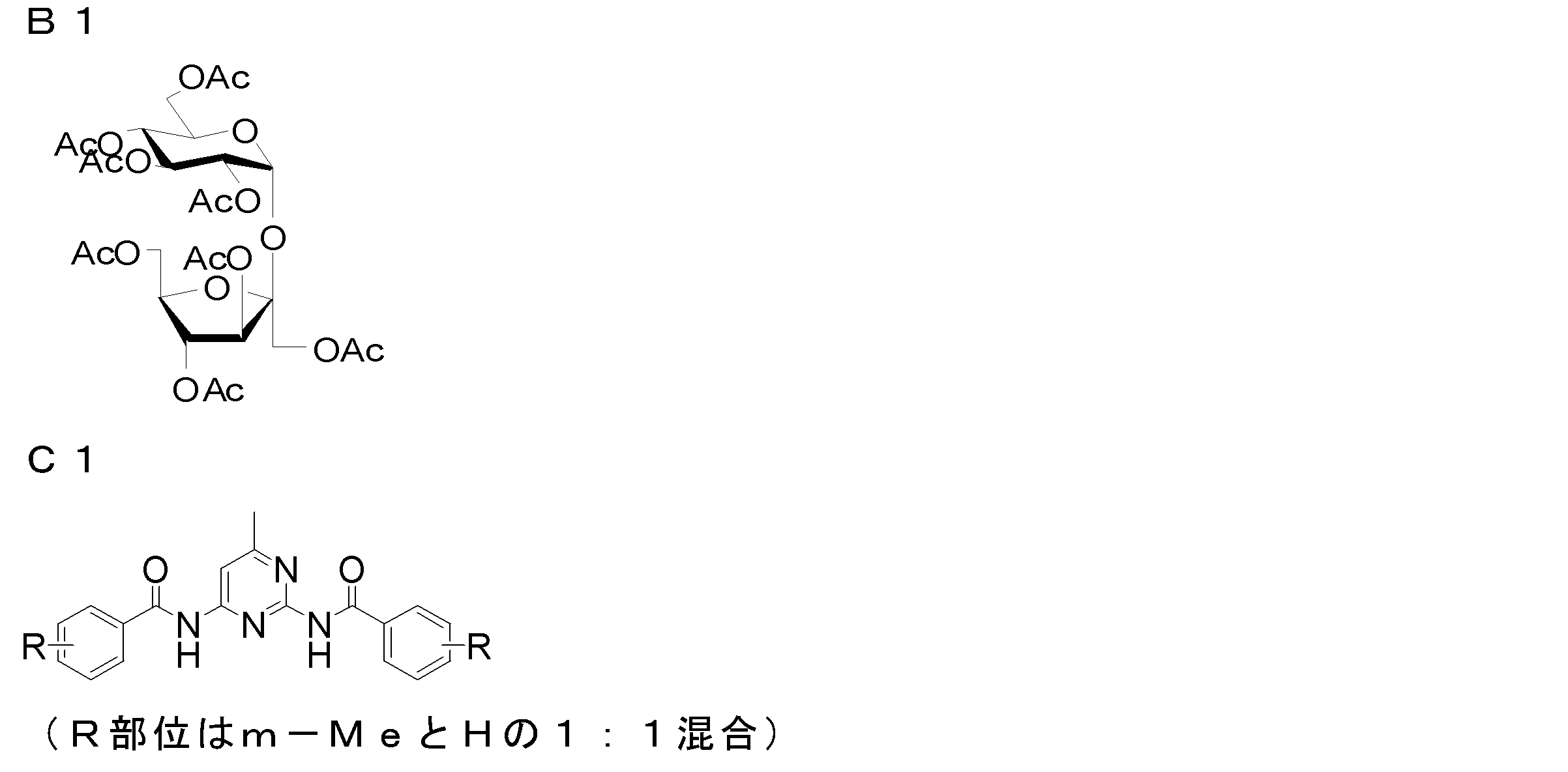
<1-2> マット剤分散液
次に上記方法で作成したセルロースアシレート溶液を含む下記組成物を分散機に投入し、マット剤分散液を調製した。
――――――――――――――――――――――――――――――――――
マット剤分散液
――――――――――――――――――――――――――――――――――
・マット剤(アエロジルR972) 0.2質量部
・メチレンクロライド 72.4質量部
・メタノール 10.8質量部
・セルロースアシレート溶液 10.3質量部
――――――――――――――――――――――――――――――――――
上記実施例1のセルロースアシレート溶液を100質量部、マット剤分散液をセルロースアシレート樹脂に対して無機微粒子が0.02質量部となる量を混合し、実施例1の製膜用ドープを調製した。得られたドープについて、25℃、1Hzで振動粘度を測定したところ、60Pa・sであった。
次に上記方法で作成したセルロースアシレート溶液を含む下記組成物を分散機に投入し、マット剤分散液を調製した。
――――――――――――――――――――――――――――――――――
マット剤分散液
――――――――――――――――――――――――――――――――――
・マット剤(アエロジルR972) 0.2質量部
・メチレンクロライド 72.4質量部
・メタノール 10.8質量部
・セルロースアシレート溶液 10.3質量部
――――――――――――――――――――――――――――――――――
上記実施例1のセルロースアシレート溶液を100質量部、マット剤分散液をセルロースアシレート樹脂に対して無機微粒子が0.02質量部となる量を混合し、実施例1の製膜用ドープを調製した。得られたドープについて、25℃、1Hzで振動粘度を測定したところ、60Pa・sであった。
(3)流延
上述のドープを、バンド流延機の支持体上へ1.0mmのリップクリアランスの流延ダイから膜状に押し出し、流延を行った。なお、バンドはSUS製であった。
上述のドープを、バンド流延機の支持体上へ1.0mmのリップクリアランスの流延ダイから膜状に押し出し、流延を行った。なお、バンドはSUS製であった。
(4)剥離、乾燥
流延されて得られたウェブ(フィルム)を、支持体温度12℃の剥離点でバンドから剥離した。その後、クリップでウェブの両端をクリップして搬送するテンター装置を用いて該テンター装置内で20分間乾燥した。
流延されて得られたウェブ(フィルム)を、支持体温度12℃の剥離点でバンドから剥離した。その後、クリップでウェブの両端をクリップして搬送するテンター装置を用いて該テンター装置内で20分間乾燥した。
(5)延伸
得られたウェブ(フィルム)をバンドから剥離し、クリップに挟み、フィルム全体の質量に対する残留溶媒量が30~5%の状態のときに固定端一軸延伸の条件で、下記表3aに記載の延伸倍率でテンターを用いてフィルム搬送方向に直交する方向(横方向、TD方向)に延伸した。また、バンドの剥離からこれまでの操作でフィルムにかかっていたフィルム搬送方向(縦方向、MD方向)への延伸倍率を下記表に記載した。
その後にフィルムからクリップを外して110℃で30分間乾燥させた。
得られたウェブ(フィルム)をバンドから剥離し、クリップに挟み、フィルム全体の質量に対する残留溶媒量が30~5%の状態のときに固定端一軸延伸の条件で、下記表3aに記載の延伸倍率でテンターを用いてフィルム搬送方向に直交する方向(横方向、TD方向)に延伸した。また、バンドの剥離からこれまでの操作でフィルムにかかっていたフィルム搬送方向(縦方向、MD方向)への延伸倍率を下記表に記載した。
その後にフィルムからクリップを外して110℃で30分間乾燥させた。

(位相差フィルム4、5、6の作製)
ポリプラスチックス(株)製TOPAS6013(Tg138℃)のペレットを110℃の真空乾燥機で乾燥し、含水率を0.1%以下とした後、Tg-10℃になるように調整したホッパーに投入した。
混練押出し機で、260℃でペレット状の樹脂を溶融し、ギアポンプから送り出された溶融樹脂を濾過精度5μmのリーフディスクフィルターにて濾過し、スタティックミキサーを経由してスリット間隔0.8mm、230℃のハンガーコートダイから、ガラス転移温度のTg-5℃、Tg、Tg-10℃の設定した3連のキャストロール上に押し出し、最上流側の第1キャストロールに、線圧20kg/cm、温度Tg-7℃に設定したタッチロールを接触させ、キャスト固化し、未延伸フィルムを製膜した。
なお、タッチロールは特開平11-235747号公報の実施例1に記載の二重抑えロールと記載のあるものを用いた。但し薄肉金属外筒厚みは3mmとした。
ポリプラスチックス(株)製TOPAS6013(Tg138℃)のペレットを110℃の真空乾燥機で乾燥し、含水率を0.1%以下とした後、Tg-10℃になるように調整したホッパーに投入した。
混練押出し機で、260℃でペレット状の樹脂を溶融し、ギアポンプから送り出された溶融樹脂を濾過精度5μmのリーフディスクフィルターにて濾過し、スタティックミキサーを経由してスリット間隔0.8mm、230℃のハンガーコートダイから、ガラス転移温度のTg-5℃、Tg、Tg-10℃の設定した3連のキャストロール上に押し出し、最上流側の第1キャストロールに、線圧20kg/cm、温度Tg-7℃に設定したタッチロールを接触させ、キャスト固化し、未延伸フィルムを製膜した。
なお、タッチロールは特開平11-235747号公報の実施例1に記載の二重抑えロールと記載のあるものを用いた。但し薄肉金属外筒厚みは3mmとした。
得られた未延伸フィルムロールについて、縦延伸および横延伸を逐次行った。
縦延伸は、2対のニップロールを設置し、この間を加熱しながら出口側のニップロールの周速を入口側のニップロールの周速より速くすることで延伸し、Rthを調節するためにニップロール間の間隔(L)と延伸前のフィルム幅(W)の比L/Wを調節した。
また、横延伸はテンター延伸装置を用いた。
延伸条件について下記表に記載した。
縦延伸は、2対のニップロールを設置し、この間を加熱しながら出口側のニップロールの周速を入口側のニップロールの周速より速くすることで延伸し、Rthを調節するためにニップロール間の間隔(L)と延伸前のフィルム幅(W)の比L/Wを調節した。
また、横延伸はテンター延伸装置を用いた。
延伸条件について下記表に記載した。

位相差フィルム1~6のRe値、Rth値、遅相軸角度、遅相軸レンジを所定の方法で測定し、P値を算出した。それらを下記表に示した。

2.偏光板の作製
単体透過率44.1%、偏光度99.95%である長尺状のポリビニルアルコール偏光膜フィルム(吸収軸が搬送方向)の両側に、苛性ソーダ水溶液で鹸化処理済みの保護フィルムを一方の面に、上記の位相差フィルム1~4を反対の面に、市販の接着剤を用いて、3枚を長手方向に揃えて貼り合わせながらロール形態の偏光板をそれぞれ作製した。保護フィルムとしては市販のセルローストリアシレートフィルム(フジタックTG40、富士フイルム(株)製)を使用した。
位相差フィルム5、6はMD方向と偏光膜の吸収軸が直交するようにシート毎に貼り合わせ、保護フィルムとして市販のセルローストリアシレートフィルム(フジタックTG40、富士フイルム(株)製)を用いて偏光板を作製した。
TNモード液晶用の偏光板とするため、自動打抜き機を用いて所定のサイズになるように45°打ち抜きを行った。
なお、上記偏光板において、遅相軸角度が0°は、偏光膜の透過軸に平行、遅相軸角度が90°は、偏光膜の透過軸に直交となる。
単体透過率44.1%、偏光度99.95%である長尺状のポリビニルアルコール偏光膜フィルム(吸収軸が搬送方向)の両側に、苛性ソーダ水溶液で鹸化処理済みの保護フィルムを一方の面に、上記の位相差フィルム1~4を反対の面に、市販の接着剤を用いて、3枚を長手方向に揃えて貼り合わせながらロール形態の偏光板をそれぞれ作製した。保護フィルムとしては市販のセルローストリアシレートフィルム(フジタックTG40、富士フイルム(株)製)を使用した。
位相差フィルム5、6はMD方向と偏光膜の吸収軸が直交するようにシート毎に貼り合わせ、保護フィルムとして市販のセルローストリアシレートフィルム(フジタックTG40、富士フイルム(株)製)を用いて偏光板を作製した。
TNモード液晶用の偏光板とするため、自動打抜き機を用いて所定のサイズになるように45°打ち抜きを行った。
なお、上記偏光板において、遅相軸角度が0°は、偏光膜の透過軸に平行、遅相軸角度が90°は、偏光膜の透過軸に直交となる。
5.液晶表示装置の作製と評価
バックライトに用いるためのプリズムシートを下記のように作製した。
バックライトに用いるためのプリズムシートを下記のように作製した。
<凹凸部(プリズム部)を形成した支持体の作製>
前記凹凸部(プリズム部)を形成した支持体として、下記のようにしてプリズムシートを作製した。
〔プリズム層塗布液の調整〕
下記処方のプリズム層塗布液を調整した。
下記の組成物をミキシングタンクに投入し、50℃に加熱しながら攪拌して、各成分を溶解し、塗布液を調製した。なお、硬化後のプリズム層の屈折率は1.59であった。前記プリズム層の屈折率は、同一の液を平坦な塗布膜として形成し、プリズムカプラー屈折率測定機(SPA4000 Sairon Technology Inc.)により測定した。
・エベクリル3700(ダイセルUBC(株)製) 2.55質量部
・NKエステルBPE-200(新中村化学(株)製) 0.85質量部
・アロニックスM-110(東亞合成(株)製) 0.85質量部
・ニューフロンティアBR-31(第一工業製薬(株)製)4.25質量部
・メチルエチルケトン 2.89質量部
・ルシリンTPO-L(BASF(株)製) 0.17質量部
前記凹凸部(プリズム部)を形成した支持体として、下記のようにしてプリズムシートを作製した。
〔プリズム層塗布液の調整〕
下記処方のプリズム層塗布液を調整した。
下記の組成物をミキシングタンクに投入し、50℃に加熱しながら攪拌して、各成分を溶解し、塗布液を調製した。なお、硬化後のプリズム層の屈折率は1.59であった。前記プリズム層の屈折率は、同一の液を平坦な塗布膜として形成し、プリズムカプラー屈折率測定機(SPA4000 Sairon Technology Inc.)により測定した。
・エベクリル3700(ダイセルUBC(株)製) 2.55質量部
・NKエステルBPE-200(新中村化学(株)製) 0.85質量部
・アロニックスM-110(東亞合成(株)製) 0.85質量部
・ニューフロンティアBR-31(第一工業製薬(株)製)4.25質量部
・メチルエチルケトン 2.89質量部
・ルシリンTPO-L(BASF(株)製) 0.17質量部
〔プリズムシートAの作製〕
両面に易接着処理を施した厚み25μmのPET製の支持体の第一の表面に、前記で調製したプリズム層塗布液を乾燥質量で14g/m2となるように塗布し、80℃で1分間乾燥させた後、該プリズム層を、断面形状が頂角90°の二等辺三角形であり、ピッチ(底辺の長さ)50μmのストライプ状にプリズム形状が彫刻された金属の型(金型)に押し当てた。この押し当て状態で、前記PET製支持体の第二の表面側から、高圧水銀灯により露光し、膜を硬化させ、金型から剥離し、プリズムシートA(凹凸部を形成した支持体)を得た。
両面に易接着処理を施した厚み25μmのPET製の支持体の第一の表面に、前記で調製したプリズム層塗布液を乾燥質量で14g/m2となるように塗布し、80℃で1分間乾燥させた後、該プリズム層を、断面形状が頂角90°の二等辺三角形であり、ピッチ(底辺の長さ)50μmのストライプ状にプリズム形状が彫刻された金属の型(金型)に押し当てた。この押し当て状態で、前記PET製支持体の第二の表面側から、高圧水銀灯により露光し、膜を硬化させ、金型から剥離し、プリズムシートA(凹凸部を形成した支持体)を得た。
<白色反射層用塗布液の調製>
下記処方で、光学調整部形成用の白色反射層用塗布液を調整した。
[ホワイト顔料分散母液の組成]
・ポリビニルブチラール(エスレックB BL-SH、積水化学工業(株)製)
2.7質量部
・ルチル型酸化チタン(JR805、テイカ(株)製、質量平均粒子径0.29μm) 35.0質量部
・分散助剤(ソルスパース20000、アビシア(株)製)0.35質量部
・n-プロピルアルコール 62.0質量部
上記組成物を、アイガー社製モーターミルM50によりジルコニアビーズを用いて分散し、ホワイト顔料分散母液を調製した。
下記処方で、光学調整部形成用の白色反射層用塗布液を調整した。
[ホワイト顔料分散母液の組成]
・ポリビニルブチラール(エスレックB BL-SH、積水化学工業(株)製)
2.7質量部
・ルチル型酸化チタン(JR805、テイカ(株)製、質量平均粒子径0.29μm) 35.0質量部
・分散助剤(ソルスパース20000、アビシア(株)製)0.35質量部
・n-プロピルアルコール 62.0質量部
上記組成物を、アイガー社製モーターミルM50によりジルコニアビーズを用いて分散し、ホワイト顔料分散母液を調製した。
[白色反射層塗布液の組成]
・上記で調製されたホワイト顔料分散母液 1,200質量部
・ワックス系化合物
・ステアリン酸アミド(ニュートロン2、日本精化(株)製) 5.7質量部
・ベヘン酸アミド(ダイヤミッドBM、日本化成(株)製) 5.7質量部
・ラウリン酸アミド(ダイヤミッドY、日本化成(株)製) 5.7質量部
・パルミチン酸アミド(ダイヤミンドKP、日本化成(株)製) 5.7質量部
・エルカ酸アミド(ダイヤミッドL-200、日本化成(株)製)5.7質量部
・オレイン酸アミド(ダイヤミッドO-200、日本化成(株)製) 5.7質量部
・ロジン(KE-311、荒川化学(株)製、成分:樹脂酸80~97%;樹脂酸成分:アビエチン酸30~40%、ネオアビエチン酸10~20%、ジヒドロアビエチン酸14%、テトラヒドロアビエチン酸14%)
80.0質量部
・界面活性剤(メガファックF-780F、固形分30%、大日本インキ化学工業社製) 16.0質量部
・n-プロピルアルコール 1,600質量部
・メチルエチルケトン 580質量部
・上記で調製されたホワイト顔料分散母液 1,200質量部
・ワックス系化合物
・ステアリン酸アミド(ニュートロン2、日本精化(株)製) 5.7質量部
・ベヘン酸アミド(ダイヤミッドBM、日本化成(株)製) 5.7質量部
・ラウリン酸アミド(ダイヤミッドY、日本化成(株)製) 5.7質量部
・パルミチン酸アミド(ダイヤミンドKP、日本化成(株)製) 5.7質量部
・エルカ酸アミド(ダイヤミッドL-200、日本化成(株)製)5.7質量部
・オレイン酸アミド(ダイヤミッドO-200、日本化成(株)製) 5.7質量部
・ロジン(KE-311、荒川化学(株)製、成分:樹脂酸80~97%;樹脂酸成分:アビエチン酸30~40%、ネオアビエチン酸10~20%、ジヒドロアビエチン酸14%、テトラヒドロアビエチン酸14%)
80.0質量部
・界面活性剤(メガファックF-780F、固形分30%、大日本インキ化学工業社製) 16.0質量部
・n-プロピルアルコール 1,600質量部
・メチルエチルケトン 580質量部
<白色反射シートの作製>
厚み25μmのPET製支持体上に、前記で調製した白色反射層塗布液を、乾燥膜厚が2μmになるように塗布し、100℃で2分間乾燥させ、白色反射シートを作製した。
厚み25μmのPET製支持体上に、前記で調製した白色反射層塗布液を、乾燥膜厚が2μmになるように塗布し、100℃で2分間乾燥させ、白色反射シートを作製した。
<ポジ型感光層用塗布液の調製>
下記処方のポジ型感光層用塗布液を調製した。
・フェノールノボラック樹脂
(住友デュレズ株式会社製、PR-50716、融点:76℃) 2.5質量部
・フェノールノボラック樹脂
(住友デュレズ株式会社製、PR-51600B、融点:55℃)3.5質量部
・1,2-ナフトキノン(2)ジアジド-4-スルフォン酸クミルフェノールエステル
2.0質量部
・メチルエチルケトン 40質量部
・プロピレングリコールモノメチルエーテルアセテート 20質量部
・界面活性剤(大日本インキ株式会社製、メガファックF-176PF)
0.1質量部
下記処方のポジ型感光層用塗布液を調製した。
・フェノールノボラック樹脂
(住友デュレズ株式会社製、PR-50716、融点:76℃) 2.5質量部
・フェノールノボラック樹脂
(住友デュレズ株式会社製、PR-51600B、融点:55℃)3.5質量部
・1,2-ナフトキノン(2)ジアジド-4-スルフォン酸クミルフェノールエステル
2.0質量部
・メチルエチルケトン 40質量部
・プロピレングリコールモノメチルエーテルアセテート 20質量部
・界面活性剤(大日本インキ株式会社製、メガファックF-176PF)
0.1質量部
<アルカリ現像液の調製>
下記組成のアルカリ現像液を調製した。
・炭酸ナトリウム 59質量部
・重炭酸ナトリウム 32質量部
・水 720質量部
・ブチルセロソルブ 1質量部
下記組成のアルカリ現像液を調製した。
・炭酸ナトリウム 59質量部
・重炭酸ナトリウム 32質量部
・水 720質量部
・ブチルセロソルブ 1質量部
<集光性のプリズムシートBの作製>
図5に示すように、前記で作製したプリズムシートA(凹凸部5を形成した支持体2)の平坦な第二の表面4側に、前記で調製したポジ型感光層用塗布液を、乾燥膜厚が0.5μmになるように塗布し、100℃で2分間乾燥させ、前記支持体2の第二の表面4上にポジ型感光層8を形成した。
次に、図6に示すように、前記支持体2の凹凸部5を形成した第一の表面3側から、平行光線照射機(マスクアライメント装置M-2L、ミカサ(株)製)を用いて、平坦な前記第二の表面4の法線方向に平行に紫外線照射し、前記ポジ型感光層を露光した。図6に符号6で示す部分が、光の不通過部(光束密度の低い部分)である。
図5に示すように、前記で作製したプリズムシートA(凹凸部5を形成した支持体2)の平坦な第二の表面4側に、前記で調製したポジ型感光層用塗布液を、乾燥膜厚が0.5μmになるように塗布し、100℃で2分間乾燥させ、前記支持体2の第二の表面4上にポジ型感光層8を形成した。
次に、図6に示すように、前記支持体2の凹凸部5を形成した第一の表面3側から、平行光線照射機(マスクアライメント装置M-2L、ミカサ(株)製)を用いて、平坦な前記第二の表面4の法線方向に平行に紫外線照射し、前記ポジ型感光層を露光した。図6に符号6で示す部分が、光の不通過部(光束密度の低い部分)である。
次いで、前記で調製したアルカリ現像液を用いて、ポジ型感光層の露光部を洗い流し、図7に示すように、支持体2の第二の表面4であって光の不通過部6に、部分的にポジ型感光層8を有する支持体2を得た。
図8に示すように、上記部分的にポジ型感光層8を有する支持体2の、前記ポジ感光層8が形成された第二の表面4に、前記で作製した白色反射層9を設けた白色反射シート10を、粘着性を有する前記ポジ型感光層8に第二の表面4に白色反射層9が接触するように配置し、ラミネート装置にて熱ラミネート(速度:0.5m/min.加熱温度:80℃)した。その後、図9に示すように、白色反射シート10を支持体2から剥離することにより、前記ポジ型感光層8の形成部に12μm巾のストライプ状に、白色反射層9が転写された支持体2を得て、プリズムシートBを形成した。該白色反射層9が、サイドローブ防止部7であり、その光反射率は、70%であった。
図8に示すように、上記部分的にポジ型感光層8を有する支持体2の、前記ポジ感光層8が形成された第二の表面4に、前記で作製した白色反射層9を設けた白色反射シート10を、粘着性を有する前記ポジ型感光層8に第二の表面4に白色反射層9が接触するように配置し、ラミネート装置にて熱ラミネート(速度:0.5m/min.加熱温度:80℃)した。その後、図9に示すように、白色反射シート10を支持体2から剥離することにより、前記ポジ型感光層8の形成部に12μm巾のストライプ状に、白色反射層9が転写された支持体2を得て、プリズムシートBを形成した。該白色反射層9が、サイドローブ防止部7であり、その光反射率は、70%であった。
〔プリズムシートCの作製〕
両面に易接着処理を施した厚み25μmのPET製の支持体の第一の表面に、前記で調製したプリズム層塗布液を乾燥質量で14g/m2となるように塗布し、80℃で1分間乾燥させた後、該プリズム層を、断面形状が頂角110°の二等辺三角形であり、ピッチ(底辺の長さ)50μmのストライプ状にプリズム形状が彫刻された金属の型(金型)に押し当てた。この押し当て状態で、前記PET製支持体の第二の表面側から、高圧水銀灯により露光し、膜を硬化させ、金型から剥離し、プリズムシートC(凹凸部を形成した支持体)を得た。
両面に易接着処理を施した厚み25μmのPET製の支持体の第一の表面に、前記で調製したプリズム層塗布液を乾燥質量で14g/m2となるように塗布し、80℃で1分間乾燥させた後、該プリズム層を、断面形状が頂角110°の二等辺三角形であり、ピッチ(底辺の長さ)50μmのストライプ状にプリズム形状が彫刻された金属の型(金型)に押し当てた。この押し当て状態で、前記PET製支持体の第二の表面側から、高圧水銀灯により露光し、膜を硬化させ、金型から剥離し、プリズムシートC(凹凸部を形成した支持体)を得た。
<プリズムシートの設置>
作製した頂角が90°であるプリズムシートA、頂角が90°であるプリズムシートであって、さらに部分的に光反射性を有するサイドローブ防止部7が複数形成された集光性のプリズムシートであるプリズムシートB、頂角が110°であるプリズムシートCを、それぞれ凸部を液晶セル側へ向けてバックライトに設置した。
作製した頂角が90°であるプリズムシートA、頂角が90°であるプリズムシートであって、さらに部分的に光反射性を有するサイドローブ防止部7が複数形成された集光性のプリズムシートであるプリズムシートB、頂角が110°であるプリズムシートCを、それぞれ凸部を液晶セル側へ向けてバックライトに設置した。
<バックライト光の出射角度分布の測定>
上記プリズムシートを設置した液晶表示装置用バックライト光源について、輝度計(BM-7:トプコン(株))にて、光度の測定を行った。
正面を0°として、プリズムシートの集光方向に対して受光機を5°刻みで±85°走査し、プリズムシートから出射される光度の角度分布を測定し、出射角度50°から85°の範囲で測定した光量の平均値を求め、下記表に記載した(以下、「50~80°の平均値」と示すことがある。)。
なお、光度と出射角度の関係を各プリズムシートについて正面(0°)で測定した光度(cd)を基準に規格化して図10に示す。
<半値角の測定>
上記の光度と出射角度0°~85°の関係から正面(0°)で測定した光度(cd)の1/2となる出射角度を読み取り、それを半値角とした。
上記プリズムシートを設置した液晶表示装置用バックライト光源について、輝度計(BM-7:トプコン(株))にて、光度の測定を行った。
正面を0°として、プリズムシートの集光方向に対して受光機を5°刻みで±85°走査し、プリズムシートから出射される光度の角度分布を測定し、出射角度50°から85°の範囲で測定した光量の平均値を求め、下記表に記載した(以下、「50~80°の平均値」と示すことがある。)。
なお、光度と出射角度の関係を各プリズムシートについて正面(0°)で測定した光度(cd)を基準に規格化して図10に示す。
<半値角の測定>
上記の光度と出射角度0°~85°の関係から正面(0°)で測定した光度(cd)の1/2となる出射角度を読み取り、それを半値角とした。
《実施例1》
位相差フィルム(偏光板)、TNモード液晶セル、バックライト用のプリズムシート(集光シート)の組み合わせが下記表に記載した内容となるように液晶表示装置(ディスプレイ)を組み立てた。各45°打ち抜き偏光板を液晶パネルの両側に貼り付ける工程は、自動貼り付け機を用いて行った。
なお、液晶セルは市販品を使用しており、画面の長辺方向を水平方向、短辺方向を鉛直方向とするため、TNモード液晶セルの面内位相差が最大となる方向は鉛直方向となる。
各プリズムシートは、凸部を液晶セル側へ向けてあり、その集光方向は、下記表に記載するように鉛直方向、または水平方向となるように配置した。
位相差フィルム(偏光板)、TNモード液晶セル、バックライト用のプリズムシート(集光シート)の組み合わせが下記表に記載した内容となるように液晶表示装置(ディスプレイ)を組み立てた。各45°打ち抜き偏光板を液晶パネルの両側に貼り付ける工程は、自動貼り付け機を用いて行った。
なお、液晶セルは市販品を使用しており、画面の長辺方向を水平方向、短辺方向を鉛直方向とするため、TNモード液晶セルの面内位相差が最大となる方向は鉛直方向となる。
各プリズムシートは、凸部を液晶セル側へ向けてあり、その集光方向は、下記表に記載するように鉛直方向、または水平方向となるように配置した。
液晶表示装置の表示性能は、25℃60%に設定された暗所にて、下記項目について評価を行った。
<正面コントラストの評価方法>
正面コントラストは、1水準のディスプレイについて、同一の偏光板を幅手方向に10点ずつ等間隔に打抜き、同一のディスプレイに貼合して作製した合計20サンプルのディスプレイについて、25℃、60%RHの環境下でコントラスト測定器(ELDIM社製、EZContrast)を用いて、正面コントラストを計測し、その平均値を求めた。
ディスプレイ01を評価基準として各ディスプレイの正面コントラスト値の相対比を以下の基準で分類評価した。Dランクを基準として示した。
A:正面コントラスト相対比が1.25以上
B:正面コントラスト相対比が1.15以上、1.25未満
C:正面コントラスト相対比が1.05以上、1.15未満
D:正面コントラスト相対比が1.05未満
正面コントラストは、1水準のディスプレイについて、同一の偏光板を幅手方向に10点ずつ等間隔に打抜き、同一のディスプレイに貼合して作製した合計20サンプルのディスプレイについて、25℃、60%RHの環境下でコントラスト測定器(ELDIM社製、EZContrast)を用いて、正面コントラストを計測し、その平均値を求めた。
ディスプレイ01を評価基準として各ディスプレイの正面コントラスト値の相対比を以下の基準で分類評価した。Dランクを基準として示した。
A:正面コントラスト相対比が1.25以上
B:正面コントラスト相対比が1.15以上、1.25未満
C:正面コントラスト相対比が1.05以上、1.15未満
D:正面コントラスト相対比が1.05未満
<正面コントラストのバラツキ評価(液晶表示装置間の正面コントラスト値の繰り返し再現性)>
上記の20サンプル同一水準のディスプレイについて、20サンプルの正面コントラスト測定値を、下記基準で評価した。Bランクを基準とする。
A:20回の内、最大値と最小値の差が正面コントラスト値の平均値に対して5%未満
B:20回の内、最大値と最小値の差が正面コントラスト値の平均値に対して5%以上、10%未満
C:20回の内、最大値と最小値の差が正面コントラスト値の平均値に対して10%以上、15%未満
D:20回の内、最大値と最小値の差が正面コントラスト値の平均値に対して15%以上
上記評価結果を下記表に示す。
上記の20サンプル同一水準のディスプレイについて、20サンプルの正面コントラスト測定値を、下記基準で評価した。Bランクを基準とする。
A:20回の内、最大値と最小値の差が正面コントラスト値の平均値に対して5%未満
B:20回の内、最大値と最小値の差が正面コントラスト値の平均値に対して5%以上、10%未満
C:20回の内、最大値と最小値の差が正面コントラスト値の平均値に対して10%以上、15%未満
D:20回の内、最大値と最小値の差が正面コントラスト値の平均値に対して15%以上
上記評価結果を下記表に示す。
正面コントラスト、正面コントラストのバラツキについて評価結果を下記表に示した。

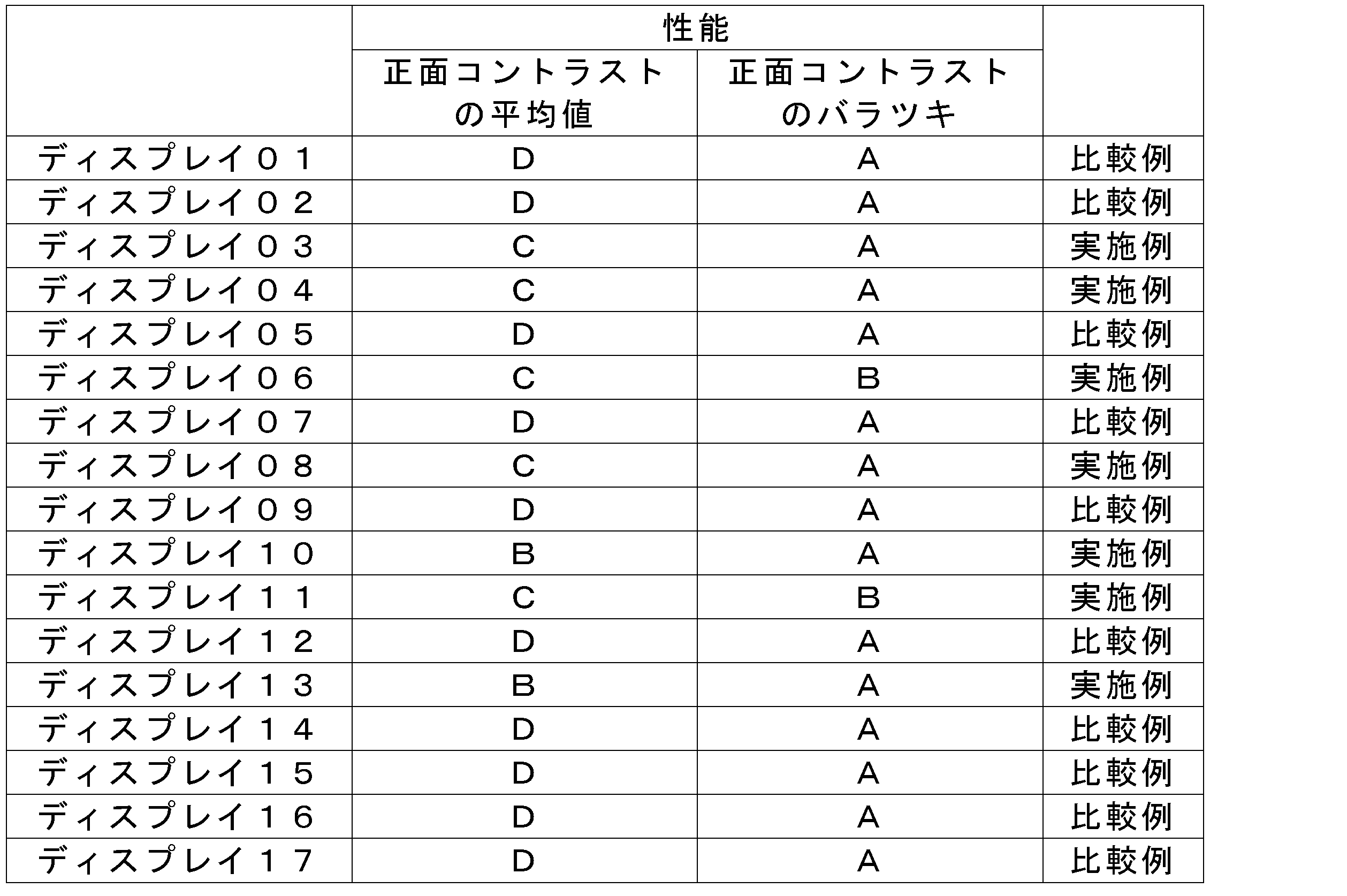
上記結果から明らかなとおり、本発明のディスプレイ(ディスプレイ03、04、06、08、10、11、13)はいずれも、正面コントラスト比が高く、さらに、バラツキが少なかった。これに対し、50~80°の平均値が12%を超える場合(ディスプレイ01、02)、位相差フィルムが式(II)の値を満たさない場合(ディスプレイ07、12)、DI値が本発明の範囲を外れる場合(ディスプレイ14~17)では、正面コントラストが劣る結果となった。
また、ディスプレイ05のように、面内位相差が最大となる方向が水平になっている場合も、正面コントラストが劣る結果となった。
また、ディスプレイ05のように、面内位相差が最大となる方向が水平になっている場合も、正面コントラストが劣る結果となった。
《実施例2》
実施例1で用いたTNモード液晶セル、および実施例1と同じ位相差フィルム、プリズムシートを用いて、下記表に示した組合せでディスプレイを作製した。
それらディスプレイを実施例1と同様に評価し、下記表に示した。なお、正面コントラスト値は、評価基準をディスプレイ21とし、その相対比を記載した。
実施例1で用いたTNモード液晶セル、および実施例1と同じ位相差フィルム、プリズムシートを用いて、下記表に示した組合せでディスプレイを作製した。
それらディスプレイを実施例1と同様に評価し、下記表に示した。なお、正面コントラスト値は、評価基準をディスプレイ21とし、その相対比を記載した。
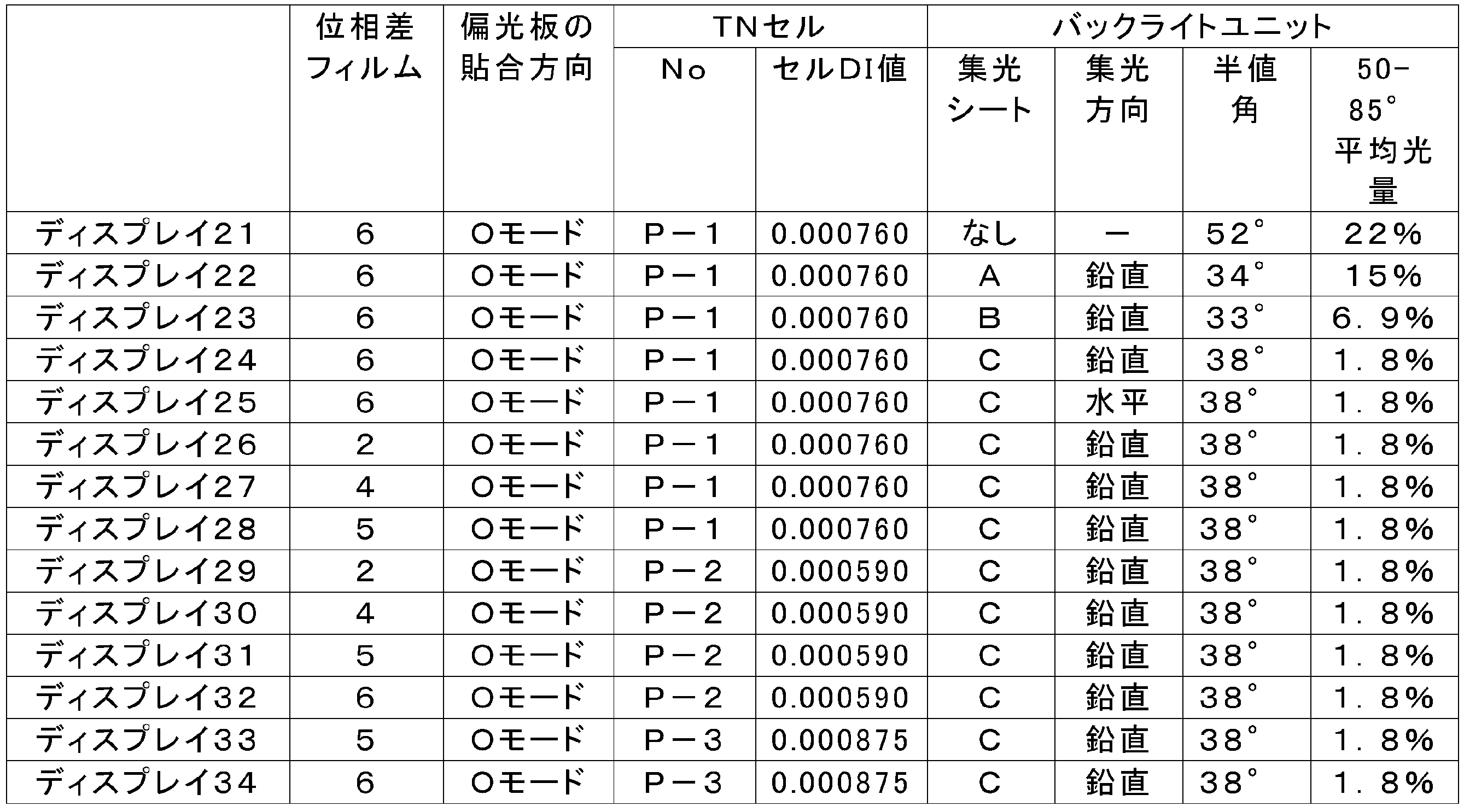
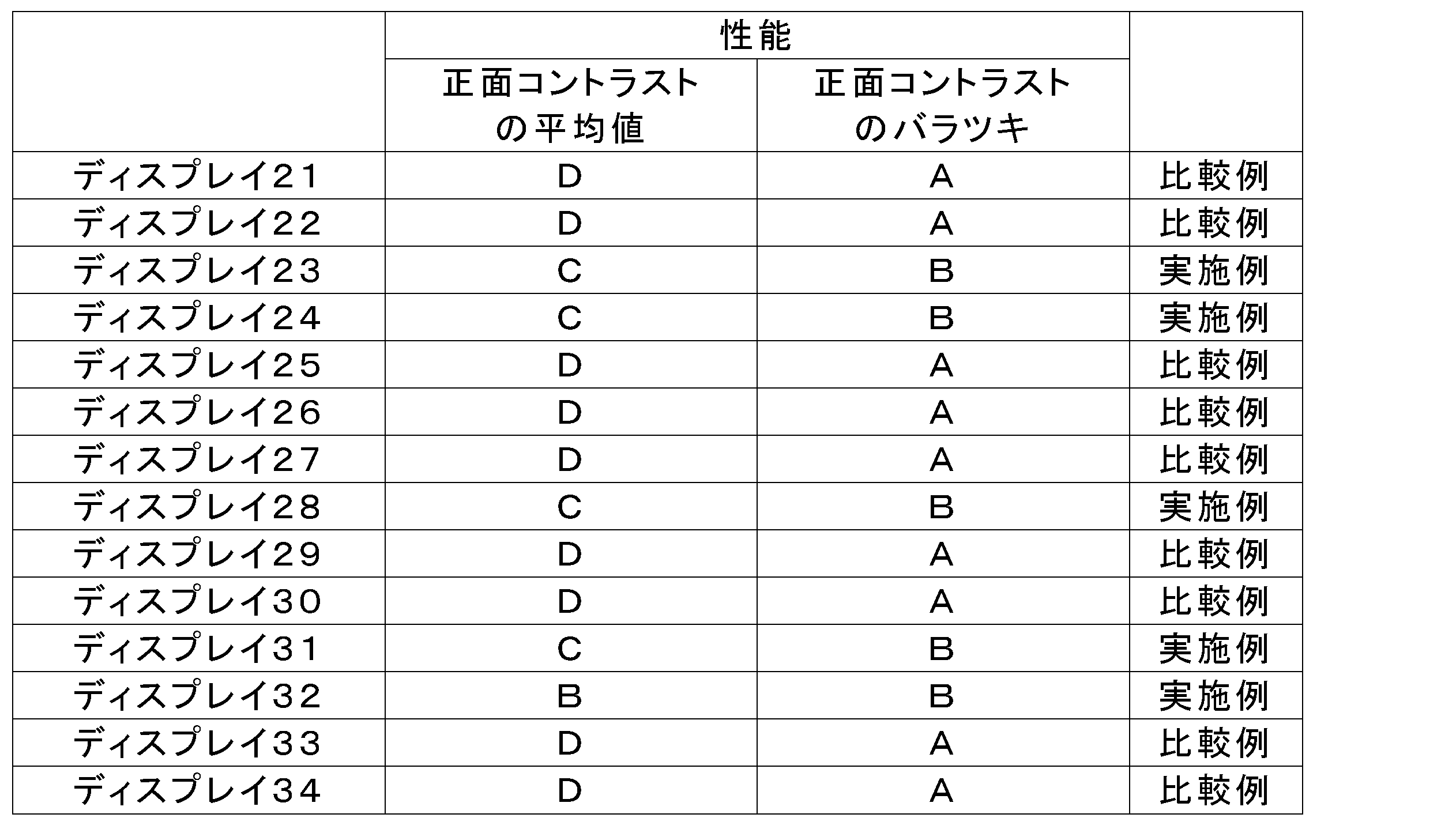
上記結果から明らかなとおり、本発明のディスプレイ(ディスプレイ23、24、28、31、32)はいずれも、正面コントラスト比が高かった。これに対し、50~80°の平均値が12%を超える場合(ディスプレイ21、22)、位相差フィルムが式(II)の値を満たさない場合(ディスプレイ26、27、29、30)、DI値が本発明の範囲を外れる場合(ディスプレイ33、34)では、正面コントラストが劣る結果となった。
尚、ディスプレイ25では、面内位相差が最大となる方向が水平になっている。
本発明のディスプレイ23、24、28、31、32の正面コントラストのバラツキは実用上許容される基準レベルに留まるが、この理由としてはOモードで使用する位相差フィルムのP値がEモードで使用する位相差フィルムのP値よりも大きいことが挙げられる。
尚、ディスプレイ25では、面内位相差が最大となる方向が水平になっている。
本発明のディスプレイ23、24、28、31、32の正面コントラストのバラツキは実用上許容される基準レベルに留まるが、この理由としてはOモードで使用する位相差フィルムのP値がEモードで使用する位相差フィルムのP値よりも大きいことが挙げられる。
《実施例3》
位相差フィルム4の縦延伸および横延伸の倍率のみ変更して位相差フィルム7及び8を作製した。延伸条件について下記表に記載した。

位相差フィルム4の縦延伸および横延伸の倍率のみ変更して位相差フィルム7及び8を作製した。延伸条件について下記表に記載した。
位相差フィルム7、8のRe値、Rth値、遅相軸角度、遅相軸レンジを所定の方法で測定し、P値を算出した。それらを下記表に示した。

実施例1で用いたTNモード液晶セル、および実施例1と同じ位相差フィルム、プリズムシートを用いて、下記表に示した組合せで46ディスプレイを作製した。
それらディスプレイを実施例1と同様に評価し、下記表に示した。なお、正面コントラスト値は、評価基準をディスプレイ41とし、その相対比を記載した。
それらディスプレイを実施例1と同様に評価し、下記表に示した。なお、正面コントラスト値は、評価基準をディスプレイ41とし、その相対比を記載した。
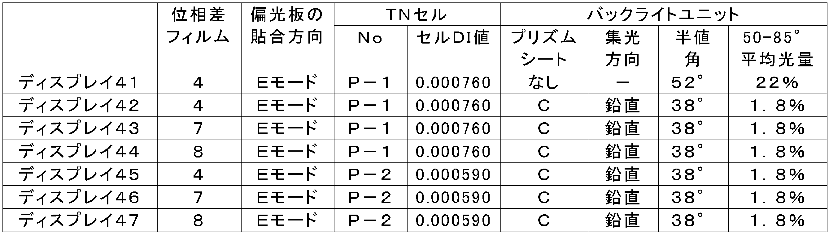
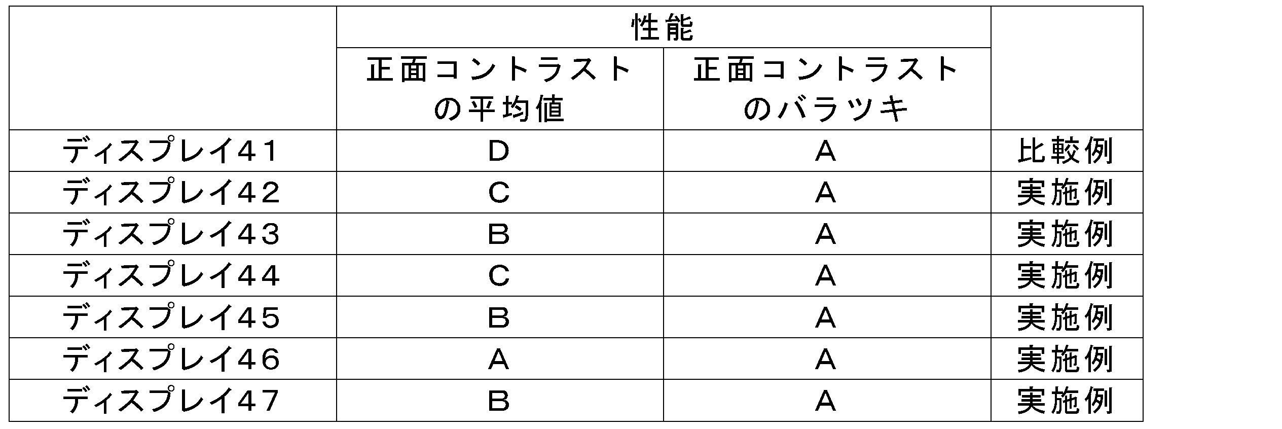
上記結果から明らかなとおり、本発明のディスプレイ(ディスプレイ42~47)はいずれも、正面コントラスト比が高く、さらに、バラツキが少なかった。遅相軸が偏光膜の透過軸に平行な位相差フィルム4に対し、遅相軸が偏光膜の透過軸と直交する位相差フィルム7を使用した場合に、正面コントラストはより良好である(ディスプレイ42と43、45と46の比較)。位相差フィルム8を使用した場合も位相差フィルム4の場合と同等の性能を得ている(ディスプレイ42、44と、45、47の比較)。
10 TNモード液晶セル
10a 視認側基板ラビング方向
10b バックライト側基板ラビング方向
12 視認側偏光膜
12a 視認側偏光膜透過軸方向
14 バックライト側偏光膜
14a バックライト側偏光膜透過軸方向
16 視認側位相差フィルム
16a 視認側位相差フィルム遅相軸平均方向
18 バックライト側位相差フィルム
18a バックライト側位相差フィルム遅相軸平均方向
20、22 保護フィルム
1 プリズムシート
2 支持体
3 第一の表面
4 第二の表面
5 凹凸部(プリズム部)
6 不通過部
7 サイドローブ防止部
8 ポジ型感光層
9 白色反射層
40 白色反射シート
41 プリズムシート
42 光源
43 拡散板
44 拡散シート
10a 視認側基板ラビング方向
10b バックライト側基板ラビング方向
12 視認側偏光膜
12a 視認側偏光膜透過軸方向
14 バックライト側偏光膜
14a バックライト側偏光膜透過軸方向
16 視認側位相差フィルム
16a 視認側位相差フィルム遅相軸平均方向
18 バックライト側位相差フィルム
18a バックライト側位相差フィルム遅相軸平均方向
20、22 保護フィルム
1 プリズムシート
2 支持体
3 第一の表面
4 第二の表面
5 凹凸部(プリズム部)
6 不通過部
7 サイドローブ防止部
8 ポジ型感光層
9 白色反射層
40 白色反射シート
41 プリズムシート
42 光源
43 拡散板
44 拡散シート
Claims (8)
- 第1の偏光膜および第2の偏光膜と、
第1の偏光膜と第2の偏光膜の間に配置された捩れ配向モード液晶セルと、
第1の偏光膜と前記液晶セルとの間に配置された第1の位相差フィルムと、
第2の偏光膜と前記液晶セルとの間に配置された第2の位相差フィルムと、
前記液晶セルの背面側に配置された、集光性のプリズムシートを備えたバックライトユニットと、を前有する液晶表示装置であって、
第1の偏光膜と第2の偏光膜は、吸収軸が互いに直交しており、
前記液晶セルは、第1の偏光膜および第2の偏光膜のそれぞれにより近い側に設けられた第1の基板および第2の基板を有し、
第1の基板および第2の基板の少なくとも一方は透明電極を有し、
第1の偏光膜の透過軸と、第1の基板のラビング方向が平行であり、
第2の偏光膜の透過軸と、第2の基板のラビング方向が平行であり、
第1の位相差フィルムおよび第2の位相差フィルムは、それぞれ、波長550nmにおける面内レターデーションRe(550)および波長550nmにおける厚み方向のレターデーションRth(550)が下記式(I)と下記式(II)を満足し、
1nm ≦ Re(550) ≦ 50nm (I)
120nm ≦ Rth(550) ≦ 220nm (II)
前記液晶セルのDepolarizing Index(DI値)が0.000800以下であり、
前記バックライトユニットから出射されたバックライト光の光量を測定したとき、該液晶表示装置の表示画面の法線に対して、前記液晶セルの面内位相差が最大となる方向に傾けられた出射角度50°から85°の範囲の光量の平均値が、前記法線方向の光量に対して12%以下である液晶表示装置。 - 第1の偏光膜および第2の偏光膜と、
第1の偏光膜と第2の偏光膜の間に捩れ配向モード液晶セルと、
第1の偏光膜と前記液晶セルとの間に配置された第1の位相差フィルムと、
第2の偏光膜と前記液晶セルとの間に配置された第2の位相差フィルムと、
前記液晶セルの背面側に配置された、集光性のプリズムシートを備えたバックライトユニットと、有する液晶表示装置であって、
第1の偏光膜と第2の偏光膜は、吸収軸が互いに直交しており、
前記液晶セルは、第1の偏光膜および第2の偏光膜のそれぞれにより近い側に設けられた第1の基板および第2の基板を有し、
第1の基板および第2の基板の少なくとも一方は透明電極を有し、
第1の偏光膜の透過軸と、第1の基板のラビング方向が直交であり、
第2の偏光膜の透過軸と、第2の基板のラビング方向が直交であり、
第1の位相差フィルムおよび第2の位相差フィルムは、それぞれ、波長550nmにおける面内レターデーションRe(550)および波長550nmにおける厚み方向のレターデーションRth(550)が下記式(III)と下記式(IV)を満足し、
60nm ≦ Re(550) ≦ 120nm (III)
120nm ≦ Rth(550) ≦ 220nm (IV)
前記液晶セルのDepolarizing Index(DI値)が0.000800以下であり、
前記バックライトユニットから出射されたバックライト光の光量を測定したとき、該液晶表示装置の表示画面の法線に対して、前記液晶セルの面内位相差が最大となる方向に傾けられた出射角度50°から85°の範囲の光量の平均値が、前記法線方向の光量に対して12%以下である液晶表示装置。 - 位相差フィルムの遅相軸レンジとRe(550)の積であるP値が、10以下である請求項1に記載の液晶表示装置:
P=遅相軸レンジ×Re(550)
但し、遅相軸レンジは、前記位相差フィルムの面内遅相軸(単位°)の最大値と最小値の差である。 - 前記バックライトユニットから出射されたバックライト光の光度の半値角が35°以上である、請求項1~3のいずれか1項に記載の液晶表示装置。
- 前記液晶セルの面内位相差が最大となる方向が、前記表示画面を視認する際に鉛直方向となる、請求項1~4のいずれか1項に記載の液晶表示装置。
- 前記プリズムシートが、凸部を液晶セル側へ向けて設置された、請求項1~5のいずれか1項に記載の液晶表示装置。
- 前記プリズムシートのプリズムの断面形状が二等辺三角形であり、その頂角が95°~130°である、請求項6に記載の液晶表示装置。
- 前記第1および第2の位相差フィルムの面内遅相軸(単位°)の最大値と最小値の差である遅相軸レンジが、それぞれ、2.0°以下である、請求項1および3~6のいずれか1項に記載の液晶表示装置。
Priority Applications (2)
| Application Number | Priority Date | Filing Date | Title |
|---|---|---|---|
| CN201380038821.8A CN104487888B (zh) | 2012-07-25 | 2013-07-17 | 扭转取向模式液晶显示装置 |
| US14/600,786 US9885910B2 (en) | 2012-07-25 | 2015-01-20 | Twisted alignment mode liquid crystal display device |
Applications Claiming Priority (2)
| Application Number | Priority Date | Filing Date | Title |
|---|---|---|---|
| JP2012-164531 | 2012-07-25 | ||
| JP2012164531 | 2012-07-25 |
Related Child Applications (1)
| Application Number | Title | Priority Date | Filing Date |
|---|---|---|---|
| US14/600,786 Continuation US9885910B2 (en) | 2012-07-25 | 2015-01-20 | Twisted alignment mode liquid crystal display device |
Publications (1)
| Publication Number | Publication Date |
|---|---|
| WO2014017343A1 true WO2014017343A1 (ja) | 2014-01-30 |
Family
ID=49997157
Family Applications (1)
| Application Number | Title | Priority Date | Filing Date |
|---|---|---|---|
| PCT/JP2013/069348 Ceased WO2014017343A1 (ja) | 2012-07-25 | 2013-07-17 | 捩れ配向モード液晶表示装置 |
Country Status (3)
| Country | Link |
|---|---|
| US (1) | US9885910B2 (ja) |
| CN (1) | CN104487888B (ja) |
| WO (1) | WO2014017343A1 (ja) |
Families Citing this family (7)
| Publication number | Priority date | Publication date | Assignee | Title |
|---|---|---|---|---|
| JP2017040757A (ja) * | 2015-08-19 | 2017-02-23 | コニカミノルタ株式会社 | 位相差フィルム、偏光板および液晶表示装置 |
| CN105137637A (zh) * | 2015-09-23 | 2015-12-09 | 武汉华星光电技术有限公司 | 液晶显示组件、液晶显示装置及终端 |
| JP6801667B2 (ja) * | 2015-09-30 | 2020-12-16 | 日本ゼオン株式会社 | 液晶表示装置 |
| JP7280009B2 (ja) * | 2016-04-18 | 2023-05-23 | 日東電工株式会社 | 液晶表示装置 |
| CN107045234B (zh) * | 2017-03-07 | 2020-06-09 | 合肥联宝信息技术有限公司 | 液晶显示面板及显示控制方法 |
| US12135478B2 (en) * | 2022-02-04 | 2024-11-05 | Sharp Display Technology Corporation | Liquid crystal panel and display device |
| US11988351B1 (en) * | 2023-06-12 | 2024-05-21 | Sl Corporation | Lamp for vehicle and vehicle including the same |
Citations (3)
| Publication number | Priority date | Publication date | Assignee | Title |
|---|---|---|---|---|
| JP2007256589A (ja) * | 2006-03-23 | 2007-10-04 | Fujifilm Corp | 液晶表示装置 |
| JP2009037231A (ja) * | 2007-07-06 | 2009-02-19 | Fujifilm Corp | Tnモード液晶表示装置、ならびにそれに用いられる光学補償シート及び偏光板 |
| JP2013041240A (ja) * | 2011-07-20 | 2013-02-28 | Fujifilm Corp | 液晶表示装置 |
Family Cites Families (11)
| Publication number | Priority date | Publication date | Assignee | Title |
|---|---|---|---|---|
| JP3028844B2 (ja) | 1990-10-26 | 2000-04-04 | 株式会社日立製作所 | 液晶表示装置 |
| US5699136A (en) | 1992-11-18 | 1997-12-16 | Fuji Photo Film Co., Ltd. | Negative uniaxial anisotropic element and method for manufacturing the same |
| JP2565644B2 (ja) | 1992-11-18 | 1996-12-18 | 富士写真フイルム株式会社 | 光学異方素子及びその製造方法 |
| JPH10186356A (ja) | 1996-12-27 | 1998-07-14 | Nippon Oil Co Ltd | 液晶表示素子用光学補償フィルム |
| JP2005105139A (ja) * | 2003-09-30 | 2005-04-21 | Fuji Photo Film Co Ltd | セルロースアシレートフィルム及びそれを用いた偏光板、液晶表示装置 |
| CN101258433B (zh) * | 2005-09-07 | 2010-12-22 | 富士胶片株式会社 | 光学补偿薄膜、其制造方法、以及使用其的偏振片和液晶显示装置 |
| TWI447443B (zh) * | 2006-02-28 | 2014-08-01 | Fujifilm Corp | 偏光板及液晶顯示器 |
| US20080044596A1 (en) * | 2006-08-21 | 2008-02-21 | Fujifilm Corporation | Polymer film, production method thereof, and polarizing plate and liquid crystal display device using the polymer film |
| JP4697098B2 (ja) * | 2006-09-05 | 2011-06-08 | 東ソー株式会社 | 位相差フィルム |
| JP2008089802A (ja) * | 2006-09-29 | 2008-04-17 | Fujifilm Corp | セルロースアシレートフィルム、光学補償フィルム、偏光板、液晶表示装置とセルロースアシレートフィルムの製造方法 |
| JP2009053684A (ja) * | 2007-07-30 | 2009-03-12 | Fujifilm Corp | 位相差フィルム、偏光板、及びそれを用いた液晶表示装置 |
-
2013
- 2013-07-17 CN CN201380038821.8A patent/CN104487888B/zh active Active
- 2013-07-17 WO PCT/JP2013/069348 patent/WO2014017343A1/ja not_active Ceased
-
2015
- 2015-01-20 US US14/600,786 patent/US9885910B2/en not_active Expired - Fee Related
Patent Citations (3)
| Publication number | Priority date | Publication date | Assignee | Title |
|---|---|---|---|---|
| JP2007256589A (ja) * | 2006-03-23 | 2007-10-04 | Fujifilm Corp | 液晶表示装置 |
| JP2009037231A (ja) * | 2007-07-06 | 2009-02-19 | Fujifilm Corp | Tnモード液晶表示装置、ならびにそれに用いられる光学補償シート及び偏光板 |
| JP2013041240A (ja) * | 2011-07-20 | 2013-02-28 | Fujifilm Corp | 液晶表示装置 |
Also Published As
| Publication number | Publication date |
|---|---|
| CN104487888B (zh) | 2017-04-05 |
| US20150168780A1 (en) | 2015-06-18 |
| US9885910B2 (en) | 2018-02-06 |
| CN104487888A (zh) | 2015-04-01 |
Similar Documents
| Publication | Publication Date | Title |
|---|---|---|
| US9885910B2 (en) | Twisted alignment mode liquid crystal display device | |
| CN101852872B (zh) | 光散射膜的生产方法、光散射膜、起偏振片、图像显示装置和透射/半透射液晶显示装置 | |
| KR101437703B1 (ko) | 편광판 보호 필름, 편광판, 액정 표시 장치 | |
| JP5751249B2 (ja) | ハードコートフィルム、その製造方法、偏光板、及び液晶表示装置 | |
| US10025012B2 (en) | Polarizing plate and liquid crystal display device | |
| JP5380029B2 (ja) | 液晶表示装置 | |
| US9885907B2 (en) | Optical film, polarizing plate and liquid crystal display device | |
| CN101983352A (zh) | 液晶显示装置 | |
| WO2015166941A1 (ja) | 液晶表示装置 | |
| WO2012026192A1 (ja) | ハードコートフィルム、偏光板、及び液晶表示装置 | |
| KR101709419B1 (ko) | 광학 필름 및 광학 필름의 제조 방법, 편광판 및 액정 표시 장치 | |
| JP5382118B2 (ja) | 偏光板、及び液晶表示装置 | |
| JP2003075638A (ja) | 偏光板および液晶表示装置 | |
| CN102736143A (zh) | 光扩散膜及其制造方法、用于其的涂敷液、以及使用其的偏振片、液晶显示装置 | |
| KR20150093639A (ko) | 편광판 세트, 그리고 이것을 사용한 액정 패널 및 액정 표시 장치 | |
| JP2013041240A (ja) | 液晶表示装置 | |
| JP5861502B2 (ja) | 液晶表示装置 | |
| JP2013235150A (ja) | 液晶表示装置 | |
| JP2013083912A (ja) | 偏光板、及び液晶表示装置 | |
| CN108351555A (zh) | 液晶显示装置 | |
| JP2010210865A (ja) | 光学補償フィルム、光学補償フィルムの製造方法 | |
| CN101529284B (zh) | 相位差膜 | |
| JP2010211014A (ja) | ツイストネマチック型液晶表示装置、セルロースエステル系樹脂フィルムの製造方法 | |
| JP2011064852A (ja) | 光学補償フィルムとその製造方法 | |
| WO2010146910A1 (ja) | 長尺傾斜位相差フィルム、長尺傾斜位相差フィルムの製造方法、偏光板および液晶表示装置 |
Legal Events
| Date | Code | Title | Description |
|---|---|---|---|
| 121 | Ep: the epo has been informed by wipo that ep was designated in this application |
Ref document number: 13822784 Country of ref document: EP Kind code of ref document: A1 |
|
| NENP | Non-entry into the national phase |
Ref country code: DE |
|
| 122 | Ep: pct application non-entry in european phase |
Ref document number: 13822784 Country of ref document: EP Kind code of ref document: A1 |
|
| NENP | Non-entry into the national phase |
Ref country code: JP |