WO2014017265A1 - ヒューズユニット - Google Patents
ヒューズユニット Download PDFInfo
- Publication number
- WO2014017265A1 WO2014017265A1 PCT/JP2013/068223 JP2013068223W WO2014017265A1 WO 2014017265 A1 WO2014017265 A1 WO 2014017265A1 JP 2013068223 W JP2013068223 W JP 2013068223W WO 2014017265 A1 WO2014017265 A1 WO 2014017265A1
- Authority
- WO
- WIPO (PCT)
- Prior art keywords
- block
- connection end
- fusible
- fusible body
- fuse unit
- Prior art date
- Legal status (The legal status is an assumption and is not a legal conclusion. Google has not performed a legal analysis and makes no representation as to the accuracy of the status listed.)
- Ceased
Links
Images





Classifications
-
- H—ELECTRICITY
- H01—ELECTRIC ELEMENTS
- H01H—ELECTRIC SWITCHES; RELAYS; SELECTORS; EMERGENCY PROTECTIVE DEVICES
- H01H45/00—Details of relays
- H01H45/02—Bases; Casings; Covers
-
- H—ELECTRICITY
- H01—ELECTRIC ELEMENTS
- H01H—ELECTRIC SWITCHES; RELAYS; SELECTORS; EMERGENCY PROTECTIVE DEVICES
- H01H85/00—Protective devices in which the current flows through a part of fusible material and this current is interrupted by displacement of the fusible material when this current becomes excessive
- H01H85/02—Details
- H01H85/04—Fuses, i.e. expendable parts of the protective device, e.g. cartridges
- H01H85/05—Component parts thereof
- H01H85/055—Fusible members
- H01H85/12—Two or more separate fusible members in parallel
-
- H—ELECTRICITY
- H01—ELECTRIC ELEMENTS
- H01H—ELECTRIC SWITCHES; RELAYS; SELECTORS; EMERGENCY PROTECTIVE DEVICES
- H01H61/00—Electrothermal relays
- H01H61/04—Electrothermal relays wherein the thermally-sensitive member is only heated directly
-
- H—ELECTRICITY
- H01—ELECTRIC ELEMENTS
- H01H—ELECTRIC SWITCHES; RELAYS; SELECTORS; EMERGENCY PROTECTIVE DEVICES
- H01H85/00—Protective devices in which the current flows through a part of fusible material and this current is interrupted by displacement of the fusible material when this current becomes excessive
- H01H85/02—Details
- H01H85/04—Fuses, i.e. expendable parts of the protective device, e.g. cartridges
- H01H85/041—Fuses, i.e. expendable parts of the protective device, e.g. cartridges characterised by the type
- H01H85/044—General constructions or structure of low voltage fuses, i.e. below 1000 V, or of fuses where the applicable voltage is not specified
-
- H—ELECTRICITY
- H01—ELECTRIC ELEMENTS
- H01H—ELECTRIC SWITCHES; RELAYS; SELECTORS; EMERGENCY PROTECTIVE DEVICES
- H01H85/00—Protective devices in which the current flows through a part of fusible material and this current is interrupted by displacement of the fusible material when this current becomes excessive
- H01H85/02—Details
- H01H85/04—Fuses, i.e. expendable parts of the protective device, e.g. cartridges
- H01H85/05—Component parts thereof
- H01H85/143—Electrical contacts; Fastening fusible members to such contacts
-
- H—ELECTRICITY
- H01—ELECTRIC ELEMENTS
- H01H—ELECTRIC SWITCHES; RELAYS; SELECTORS; EMERGENCY PROTECTIVE DEVICES
- H01H85/00—Protective devices in which the current flows through a part of fusible material and this current is interrupted by displacement of the fusible material when this current becomes excessive
- H01H85/02—Details
- H01H85/04—Fuses, i.e. expendable parts of the protective device, e.g. cartridges
- H01H85/05—Component parts thereof
- H01H85/143—Electrical contacts; Fastening fusible members to such contacts
- H01H85/153—Knife-blade-end contacts
-
- H—ELECTRICITY
- H01—ELECTRIC ELEMENTS
- H01H—ELECTRIC SWITCHES; RELAYS; SELECTORS; EMERGENCY PROTECTIVE DEVICES
- H01H85/00—Protective devices in which the current flows through a part of fusible material and this current is interrupted by displacement of the fusible material when this current becomes excessive
- H01H85/02—Details
- H01H85/0241—Structural association of a fuse and another component or apparatus
- H01H2085/025—Structural association with a binding post of a storage battery
-
- H—ELECTRICITY
- H01—ELECTRIC ELEMENTS
- H01H—ELECTRIC SWITCHES; RELAYS; SELECTORS; EMERGENCY PROTECTIVE DEVICES
- H01H85/00—Protective devices in which the current flows through a part of fusible material and this current is interrupted by displacement of the fusible material when this current becomes excessive
- H01H85/02—Details
- H01H85/04—Fuses, i.e. expendable parts of the protective device, e.g. cartridges
- H01H85/05—Component parts thereof
- H01H85/055—Fusible members
- H01H2085/0555—Input terminal connected to a plurality of output terminals, e.g. multielectrode
Definitions
- the present invention relates to a fuse unit in which a fuse is incorporated in a conductive circuit body integrally formed with an insulating resin housing.
- a fuse unit has been proposed in which a conductive circuit body composed of a bus bar integrally formed with a fuse element (fusible body) is molded integrally with an insulating resin housing, and the circuit body and the fusible body are embedded in the resin housing. Yes.
- the fusible body is formed integrally with the circuit body, the trouble of connecting the fusible body to the circuit body is saved, and the assemblability is improved.
- the fuse thickness has the same plate thickness as that of the circuit body, that is, the same cross-sectional area, the plate thickness is required to energize the fusible body for large current. It is not possible to increase the thickness, that is, to increase the cross-sectional area. Therefore, in a fuse unit having a circuit body in which a circuit body and a fusible body are integrally formed, a resistance value corresponding to a required fuse capacity cannot be set.
- Patent Document 1 proposes a fuse unit in which a fusible body is separated from a circuit body and a fusible body in which a resistance value corresponding to a required fuse capacity is set is incorporated in the circuit body.
- a separate soluble body is joined to a circuit body by various joining methods such as welding with solder, caulking, welding with ultrasonic waves, and welding with an optical laser beam.
- an alternative fusible body can be fastened to a fastening portion provided in advance on the fusible body.
- a fusible body in which a resistance corresponding to a necessary fuse capacity is set can be joined to a circuit body, but the fusible body is joined to the circuit body by welding or caulking. Once it is joined, it cannot be easily removed, and when a soluble material is melted by overcurrent, it cannot be replaced with a new soluble material.
- the present invention can incorporate a fusible body set to a resistance value corresponding to the required fuse capacity into the circuit body, and can easily remove the fusible body melted after the fusible body is melted.
- An object of the present invention is to provide a fuse unit that can easily incorporate a soluble material.
- the fuse unit of the present invention includes a resin housing formed of an insulator, a circuit body formed of a conductor and integrally formed in the resin housing, and branching and transmitting power from the power source side to the load side, and the circuit body
- a fuse unit provided with a fusible part that melts at the time of overcurrent to the load side, wherein the circuit body is connected to the power supply side and the block side circuit body is connected to the load side
- the block side circuit body is formed with a block side first connection end to which one side of the fusible body is detachably connected, and the other side of the fusible body is formed on the block side terminal body.
- a block-side second connection end to be detachably connected is formed.
- the block-side first connection end and the block-side second connection end are bent and raised from the circuit body, and the base is bent in the surface direction of the circuit body. It is preferable that one side of the fusible body is formed with a cut-and-raised elastic portion that can be inserted between the circuit body and elastically sandwiched.
- the resin housing includes the block-side first connection end and the block-side second connection end, and is formed with a fusible body housing portion exposed to the outside. It is preferable that the accommodating part is provided with a cover composed of a front element cover and a back element cover that covers the front side and the rear side of the fusible substance accommodating part.
- the block side first connection end and the block side second connection end are provided at a plurality of locations, and the plurality of fusible bodies are connected to each other, and the cover includes the front side element cover and the back side element cover. It is preferable that partition ribs that partition the adjacent block-side first connection ends and partition the adjacent block-side second connection ends are respectively locked.
- FIG. 1A and 1B show a fuse unit according to an embodiment of the present invention, wherein FIG. 1A is a plan view showing a resin housing and a circuit body embedded in the resin housing, and FIG. 1B is a plan view showing the circuit body.
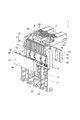
- FIG. 2 is a perspective view showing the fuse unit in the embodiment of the present invention.
- FIG. 3 is a plan view showing an element cover that covers the fusible body incorporated in the fuse unit in the embodiment of the present invention.
- FIG. 4 is a perspective view showing a block-side first connection end and a block-side second connection end of the fuse unit.
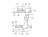
- FIG. 5 is a perspective view showing a state in which a fusible body is incorporated into the block-side first connection end and the block-side second connection end of the fuse unit.
- FIG. 1A is a plan view showing a resin housing and a circuit body embedded in the resin housing
- FIG. 1B is a plan view showing the circuit body.
- FIG. 2 is a perspective view showing the fuse
- FIG. 6 is a perspective view showing a block-side first connection end of another embodiment.
- FIG. 7 is a perspective view which shows the block side 1st connection end of other embodiment, and shows the example which provided the elastic clamping piece in the 1st connection end of the soluble body.
- the fuse unit 1 of this embodiment is formed integrally with a resin housing 2 formed of an insulator and a conductor formed of a conductor.
- the circuit body 3 that branches and transmits the power from the power source side to the load side, and the fusible body 4 that is provided in the circuit body 3 and melts when an overcurrent flows to the load side.
- the circuit body 3 is formed of a block side circuit body 17 connected to the power source side and a block side terminal body 18 connected to the load side.
- the block side first connection ends 25 and 32 to which the one connection end 45 is detachably connected are formed, and the fusible body side second connection end 46 of the fusible body 4 is detachably connected to the block side terminal body 18.
- a block-side second connection end 40 is formed.
- the resin housing 2 is formed of a first block 5 placed on the upper surface side of the power source (battery) and a second block 6 located on the side surface of the battery.
- first battery connecting portion 7 Connected to the first block 5 are a first battery connecting portion 7 connected to the battery post, an alternator connecting portion 8 to which a terminal of the electric wire terminal from the alternator is connected, and a terminal of the electric wire terminal from the second battery.
- the second battery connection portion 9 is provided.
- a first battery connecting body 19 and an alternator connecting body of a circuit body 3 to be described later embedded integrally with the resin housing 2 are embedded. 21 and a part of the second battery connector 23 are exposed.
- the second block 6 is provided with a fusible body accommodating portion 10 and a load side connecting portion 11.
- the fusible body accommodating portion 10 is provided with the block side first connection ends 25 and 32 of the circuit body 3 and the block side second connection end 40 in a state of being exposed to the outside with a predetermined interval.
- the fusible body 4 is incorporated between the block side first connection ends 25 and 32 and the block side second connection end 40. In this embodiment, four soluble bodies 4, 4, 4, 4 are incorporated.
- the load-side connection portion 11 is formed with a plurality of screw-fastening portions 12 to which the terminals of the electric wire terminals from the load side are screw-connected. A part of the block side terminal body 18 of the circuit body 3 is exposed to the outside of these screwing portions 12.
- this screwing portion 12 is provided at four locations corresponding to the four fusible bodies 4, 4, 4, and 4.
- the soluble body accommodating part 10 of the second block 6 is covered with a transparent cover 13.
- the cover 13 includes a front element cover 14 and a back element cover 15, and is attached to the second block 6 so as to sandwich the fusible body housing part 10 from the front surface side and the back surface side of the fusible body housing part 10.
- the front-side element cover 14 and the back-side element cover 15 are formed of a transparent material in substantially the same shape, a flat cover wall 48, side walls 49, 49 bent in the same direction from both sides of the cover wall 48, and the side wall 49 , 49 and three partition ribs 16, 16, 16 provided at equal intervals.
- the partition ribs 16, 16, 16 of the front element cover 14 and the back element cover 15 are in contact with each other in a state of covering the fusible body housing portion 10, thereby partitioning the four fusible bodies 4, 4, 4, 4. To do.
- the block side first connection ends 25 and 32 of the circuit body 3 are divided into four places, and the block side second connection end 40 is divided into four places.
- the conductive circuit body 3 is integrally formed in the resin housing 2 including the first block 5 and the second block 6 described above.
- the resin housing 2 in which the circuit body 3 is integrally molded is molded in a substantially flat shape as shown in FIG. 1A, and the exposed portion 30 of the circuit body 3 provided between the first block 5 and the second block 6.
- the F-shaped fuse unit 1 is formed by being bent at a substantially right angle along the folding line L.
- the fusible body 4 includes rectangular fusible body side first connection ends 45 and fusible body side second connection ends 46 formed at both ends, and these fusible body side first connections.
- An end 45 and a fusible portion 47 which is provided between the fusible body side second connection ends 46 and is welded with tin are formed.
- the circuit body 3 in which the fusible body 4 is incorporated is formed by punching a conductive plate, and most of the circuit body 3 is integrally molded in the first block 5 and embedded therein. It is formed of a body 17 and a block-side terminal body 18 that is integrally molded and embedded in the second block 6.
- the block side circuit body 17 includes a first battery connection body 19, an alternator connection body 21 that is connected to the first battery connection body 19 via the fusible portion 20 and is disposed on one side of the first battery connection body 19.
- the second battery connector 23 is connected to the first battery connector 19 via the fusible part 22 and disposed on the other side of the first battery connector 19.
- the first battery connection body 19 is formed with a first battery connection end 24 provided on one side and a block side first connection end 25 provided on the other side. As described above, the first battery connection end 24 is disposed in a state of being exposed to the first battery connection portion 7 of the first block 5, and the post on the upper surface of the battery is inserted into the through hole 26 to be screwed. Are connected to the block side circuit body 17.
- the block-side first connection end 25 is arranged in a state of being exposed to the fusible body accommodating portion 10, and three block-side first connection portions 27 to which one side of the fusible portion body 4 is detachably assembled are provided. It has been.
- the block-side first connection portion 27 includes a cut-and-raised base portion 28 that is cut and raised from the block-side first connection end 25 of the circuit body 3, and a cut-and-raised elastic portion 29 that is bent from the base portion 28 in the surface direction of the circuit body 3. And is formed. Then, as shown in FIG.
- one side of the fusible body 4 is elastically sandwiched by cutting and raising the fusible body side first connection end 45 and inserting it between the elastic portion 29 and the block side first connection end 25.
- the cut and raised elastic portion 29 and the block are slid by sliding one side of the fusible body 4 toward the base portion 28 (in the direction of arrow a) between the cut and raised elastic portion 29 and the block side first connection end 25. It can be elastically clamped between the side first connection ends 25.
- the fusible body side first on both sides of the fusible body 4 is larger than the size of the rectangular through-hole 36 formed after cutting and raising the base portion 28 and the cut and raised elastic portion 29 from the block side first connection end 25.
- the areas of the connection end 45 and the fusible body side second connection end 46 are set large, and in the state where the fusible body 4 is assembled, the through hole 36 is covered, and the periphery of the opening edge of the through hole 36 and the fusible body side.
- the first connection end 45 and the fusible body side second connection end 46 are in contact with each other with a predetermined contact surface.
- the alternator connection body 21 disposed adjacent to the first battery connection body 19 is formed with a connection portion with the fusible portion 20 on one side, and an alternator connection in which a wire terminal from the alternator is connected to an intermediate portion.
- An end 31 is formed, and a block-side first connection end 32 is provided on the other side.
- the alternator connection end 31 is provided with a through hole 33, and a screw 34 erected on the first block 5 passes through the through hole 33.
- the alternator and the alternator connector 21 are connected by inserting the screw 34 into the terminal of the electric wire terminal from the alternator side and fastening it together with a nut.
- the block-side first connection end 32 is disposed adjacent to the block-side first connection end 25 of the first battery connector 19, and is the same as the block-side first connection portion 27 provided at the block-side first connection end 32.
- the cut and raised base portion 28 and the cut and raised elastic portion 29 are formed, and one side of the fusible body 4 can be cut and raised to be elastically held between the elastic portion 29 and the block side first connection end 32.
- the second battery connector 23 arranged on the opposite side of the alternator connector 21 with the first battery connector 19 in between is formed with a connecting portion with a soluble portion 22 on one side, and in the middle portion.
- a second battery connection end 37 to which a wire terminal from the second battery is connected is formed.
- a through hole 38 is provided in the second battery connection end 37, and a screw 39 erected on the first block 5 passes through the through hole 38.
- the second battery and the second battery connector 23 are connected by inserting the screw 39 into the terminal of the electric wire terminal from the second battery and fastening it together with a nut.
- the block-side terminal body 18 is formed of four rectangular conductors, each having a block-side second connection end 40 on one side and a load-side connection end 41 on the other side.
- the block-side second connection ends 40 are respectively arranged in a state of being exposed to the fusible body housing portion 10, and provided with block-side second connection portions 42 that are assembled so that the other side of the fusible body 4 can be detached.
- the block side second connection portion 43 includes a cut and raised base portion 28, and a cut extending from the cut and raised base portion 28.
- a raised elastic portion 29 is formed.
- the fusible body side second connection end 46 of the fusible body 4 is inserted between the cut and raised elastic portion 29 and the block side second connecting end 40 and elastically sandwiched between the fusible body side second connecting end 46 of the fusible body 4. Can be connected to the block-side second connection end 40.
- the load side connection end 41 is disposed so as to be exposed to the screwing portion 12 of the second block 6, and a through hole 44 into which the screw 43 provided in the screwing portion 12 is inserted is provided.
- the terminal of the electric wire terminal from the load side is assembled to this screwing part 12, and the load side connection end 41 and the load side are connected by fastening together with a nut, and the soluble body incorporated in the soluble body accommodating part 10 4, the first battery connection end 24, the alternator connection end 31 and the load side are connected to supply power.
- the circuit body 3 shown in FIG. 1B is formed by punching from a plate in advance, and this circuit body 3 is integrated with the resin housing 2 as shown in FIG. Mold.
- most of the block-side circuit body 17 is embedded in the first block 5 and is integrally formed with the exposed portion 30 exposed, and the block-side first connection ends 25 and 32 and the block-side second connection end 40 are formed.
- a part of the block-side circuit body 17 and the block-side terminal body 18 are integrally formed with the second block 6 so as to be positioned in the fusible body housing portion 10.
- the fuse unit 1 is formed in a planar shape as shown in FIG.
- the circuit body 3 is bent at a substantially right angle along the bending line L of the exposed portion 30.
- the fusible body 4 is assembled between the block side first connection ends 25 and 32 and the block side second connection end 40.
- the fusible body side first connection end 45 and the fusible body side second connection end 46 of the fusible body 4 are provided at the block side first connection ends 25 and 32 and the block side second connection end 40.
- the cut and raised base 28 side in the direction of arrow a
- the cut and raised elastic part 29 and the block side It can be elastically clamped between the second connection end 40.
- the fusible body side first connection end 45 and the fusible body side second connection end 46 have different thicknesses. Can be held elastically.
- the soluble body 4 can be easily removed by cutting and raising the soluble body 4 and sliding it away from the base 28 (in the direction opposite to the arrow a direction).
- the fuse unit 1 is completed by covering the fusible body accommodating portion 10 with the cover 13.
- the fusible body side first connection end 45 of the fusible body 4 is connected to the block side first connection ends 25 and 32, and the block side second connection end 40 is acceptable.
- the fusible body 4 can be incorporated into the circuit body 3 by connecting the fusible body side second connection end 46 of the liquid body 4. In this case, since the fusible body 4 can be attached to and detached from the block side first connection ends 25 and 32 and the block side second connection end 40, the resistance value corresponding to the necessary fuse capacity can be set.
- the solution 4 can be easily incorporated into the circuit body 3.
- the fusible body can be easily incorporated into the block side first connection ends 25 and 32 and the block side second connection end 40.
- the fusible body side first connection end 45 of the fusible body 4 is cut and raised and inserted between the elastic portion 29 and the block side first connection ends 25 and 32 to be elastically clamped. Since the fusible body 4 can be incorporated into the circuit body 3 by cutting and raising the two connection ends 46 and inserting the elastic part 29 between the elastic part 29 and the block-side second connection end 40 and elastically holding them, the fusible body is incorporated into the circuit body 3. 4 can be easily incorporated.
- the fusible body 4 is melted by overcurrent and is replaced with a new fusible body 4, the fusible body 4 that has been melted and damaged is cut out and the elastic portion 29 and the block side first connection ends 25 and 32, the block side second If it removes from between the connection ends 40, cuts and raises the alternative fusible body 4 and inserts it between the elastic part 29, the block side first connection ends 25 and 32, and the block side second connection end 40 and elastically holds them. Since it is good, the replacement
- the fusible body 4 incorporated in the block-side first connection ends 25 and 32 and the block-side second connection end 40 housed in the fusible body housing portion 10 is covered with the front-side element cover 14 and the back-side element cover 15. Therefore, even if the fusible body 4 is melted by overcurrent or the like, the fragments are not scattered outside.
- the fusible body 4 incorporated in the block side first connection ends 25 and 32 and the block side second connection end 40 accommodated in the fusible body accommodating portion 10 was covered with the front side element cover 14 and the back side element cover 15.
- the adjacent block side first connection ends 25, 32 are partitioned by the partition ribs 16, 16, 16 and the adjacent block side second connection ends 40 are partitioned, so that one soluble body 4 is formed. Even if fusing, the debris will not scatter to the adjacent soluble body 4 side, and the adjacent soluble body 4 will not be blown unnecessarily.
- the block-side first connection ends 25 and 32 and the block-side second connection end 40 provided to be exposed in the fusible body housing portion 10 are formed by the cut-and-raised base portion 28 and the cut-and-raised elastic portion 29.
- the example which provided the block side 1st connection part 27 and the block side 2nd connection part 42 was shown, as a structure of the block side 1st connection part 27 and the block side 2nd connection part 42, it is restricted to the example of this embodiment. Various configurations can be used.
- an elastic clamping piece 52 is formed by cutting out the outer peripheral end 51 of the block-side first connection end 50 into a rectangular shape and bending it to the outer peripheral end side.
- the fusible body side first connection end 45 of the fusible body 4 can be inserted from between the front end side of the elastic clamping piece 52 and the outer peripheral end 51.
- the elastic clamping piece 52 is formed in an arc shape on the outer peripheral end 51 side from the continuous portion with the outer peripheral end 51 to the distal end side, and elastically clamps the soluble body side first connection end 45 of the inserted soluble body 4. be able to.
- the fusible body 4 of the fusible body 4 is slid by moving the fusible body side first connection end 45 of the fusible body 4 inserted between the elastic clamping piece 52 and the outer peripheral end 51 to the cutout portion 53 side of the outer peripheral end 51.
- the side first connection end 45 can be easily removed.
- the fusible body 4 can be detachably connected to the block side first connection end 50 (block side second connection end).
- the fusible body 4 can be detachably connected to the circuit body 3 by providing an elastic clamping piece 52 similar to the block-side first connection end 50 at the block-side second connection end.
- a rectangular notch 56 is formed in the block-side first connection end 55 at the outer peripheral end 57 of the block-side first connection end 55.
- the fusible body side first connection end 59 of the fusible body 58 is extended from one side of the fusible body side first connection end 59 and folded back toward the back surface side of the fusible body side first connection end 59.
- An elastic clamping piece 60 is formed.
- a side wall end 61 forming a notch 56 can be inserted between the back side of the fusible body side first connection end 59 and the elastic clamping piece 60.
- the fusible body 58 can be connected to the block-side first connection end 55 by inserting the side wall end 61 of the notch 56 between the elastic pinching piece 66 of the fusible body 58 and the fusible body-side first connection end 59. it can.
- the fusible body side first connection end 59 of the fusible body 58 is slid and moved toward the side wall end 61 side in a state where the fusible body side first connection end 59 of the fusible body 58 is positioned in the notch 56.
- the side wall end 61 can be easily inserted between the back side of the fusible body side first connection end 59 of the fusible body 58 and the elastic clamping piece 60.
- the side wall end 61 is elastically clamped between the back side of the fusible body side first connection end 59 of the fusible body 58 and the elastic clamping piece 60.
- the fusible body 58 can be easily detached from the block-side first connecting end 55 by sliding the fusible body side first connecting end 59 of the fusible body 58 toward the notch 56 side.
- the block side first connection end 55 can be provided by providing the elastic clamping piece 60 at the fusible body side first connection end 59 of the fusible body 58. Can be connected (assembled).
- a rectangular notch is provided at the block-side second connection end, and a similar elastic clamping piece 60 is provided at the fusible-body-side second connection end of the fusible body 58.
- the solution 58 can be easily connected to the circuit body 3 in a detachable manner.
- the fusible body can be incorporated into the circuit body by connecting one side of the fusible body to the block side first connection end and connecting the other side of the fusible body to the block side second connection end.
- the fusible body is detachable from the block side first connecting end and the block side second connecting end, so that the fusible body set to a resistance value corresponding to the required fuse capacity is used as the circuit body.
Landscapes
- Physics & Mathematics (AREA)
- Electromagnetism (AREA)
- Fuses (AREA)
Description
2 樹脂ハウジング
3 回路体
4 可溶体
10 可溶体収容部
13 カバー
14 表側エレメントカバー
15 裏側エレメントカバー
17 ブロック側回路体
18 ブロック側端子体
25、32 ブロック側第1接続端
27 ブロック側第1接続部
28 切り起こし基部
29 切り起こし弾性部
40 ブロック側第2接続端
42 ブロック側第2接続部
Claims (4)
- 絶縁体で形成された樹脂ハウジングと、
導電体で形成され前記樹脂ハウジングに一体に成型されて電源側からの電力を負荷側へ分岐伝達する回路体と、
該回路体に設けられて前記負荷側への過電流時に溶断する可溶体とを備えたヒューズユニットであって、
前記回路体は電源側に接続されるブロック側回路体と、負荷側に接続されるブロック側端子体とで形成され、
前記ブロック側回路体には前記可溶体の一側が脱着可能に接続されるブロック側第1接続端が形成され、
前記ブロック側端子体には前記可溶体の他側が脱着可能に接続されるブロック側第2接続端が形成されていることを特徴とするヒューズユニット。 - 請求項1記載のヒューズユニットであって、
前記ブロック側第1接続端と前記ブロック側第2接続端は、前記回路体から切り起こされた切り起こし基部と、この基部から前記回路体の面方向に屈曲されて前記可溶体の一側を回路体との間に挿入し弾性挟持可能な切り起こし弾性部とで形成されていることを特徴とするヒューズユニット。 - 請求項2記載のヒューズユニットであって、
前記樹脂ハウジングには、前記ブロック側第1接続端と前記ブロック側第2接続端とが収容されると共に、外部に露出する可溶体収容部が形成され、
該可溶体収容部は、可溶体収容部の表面側と裏面側から覆う表側エレメントカバーと裏側エレメントカバーからなるカバーを備えていることを特徴とするヒューズユニット。 - 請求項3に記載のヒューズユニットであって、
前記ブロック側第1接続端と前記ブロック側第2接続端が複数箇所設けられて複数個の前記可溶体が接続され、
前記表側エレメントカバーと前記裏側エレメントカバーとからなる前記カバーには、隣接する前記ブロック側第1接続端同士をそれぞれ区画し、かつ隣接する前記ブロック側第2接続端同士をそれぞれ区画する区画リブがそれぞれ形成されていることを特徴とするヒューズユニット。
Priority Applications (4)
| Application Number | Priority Date | Filing Date | Title |
|---|---|---|---|
| CN201380038750.1A CN104488060B (zh) | 2012-07-23 | 2013-07-03 | 熔断器单元 |
| DE112013003627.4T DE112013003627B4 (de) | 2012-07-23 | 2013-07-03 | Sicherungseinheit |
| KR1020157004210A KR101709284B1 (ko) | 2012-07-23 | 2013-07-03 | 퓨즈 유닛 |
| US14/602,561 US9460878B2 (en) | 2012-07-23 | 2015-01-22 | Fuse unit |
Applications Claiming Priority (2)
| Application Number | Priority Date | Filing Date | Title |
|---|---|---|---|
| JP2012-162354 | 2012-07-23 | ||
| JP2012162354A JP6007012B2 (ja) | 2012-07-23 | 2012-07-23 | ヒューズユニット |
Related Child Applications (1)
| Application Number | Title | Priority Date | Filing Date |
|---|---|---|---|
| US14/602,561 Continuation US9460878B2 (en) | 2012-07-23 | 2015-01-22 | Fuse unit |
Publications (1)
| Publication Number | Publication Date |
|---|---|
| WO2014017265A1 true WO2014017265A1 (ja) | 2014-01-30 |
Family
ID=49997081
Family Applications (1)
| Application Number | Title | Priority Date | Filing Date |
|---|---|---|---|
| PCT/JP2013/068223 Ceased WO2014017265A1 (ja) | 2012-07-23 | 2013-07-03 | ヒューズユニット |
Country Status (6)
| Country | Link |
|---|---|
| US (1) | US9460878B2 (ja) |
| JP (1) | JP6007012B2 (ja) |
| KR (1) | KR101709284B1 (ja) |
| CN (1) | CN104488060B (ja) |
| DE (1) | DE112013003627B4 (ja) |
| WO (1) | WO2014017265A1 (ja) |
Cited By (2)
| Publication number | Priority date | Publication date | Assignee | Title |
|---|---|---|---|---|
| JPWO2022080252A1 (ja) * | 2020-10-16 | 2022-04-21 | ||
| EP4553882A1 (en) * | 2023-11-13 | 2025-05-14 | Wöhner Besitz GmbH | Switching device for a busbar system |
Families Citing this family (9)
| Publication number | Priority date | Publication date | Assignee | Title |
|---|---|---|---|---|
| JP6291410B2 (ja) * | 2014-12-12 | 2018-03-14 | 矢崎総業株式会社 | ヒュージブルリンク |
| JP6230070B2 (ja) | 2014-12-12 | 2017-11-15 | 矢崎総業株式会社 | ヒュージブルリンク |
| KR200484888Y1 (ko) * | 2016-02-12 | 2017-11-03 | 엘에스산전 주식회사 | 진공전자접촉기의 퓨즈 케이스와 케이스 커버 |
| JP6340029B2 (ja) * | 2016-04-06 | 2018-06-06 | 太平洋精工株式会社 | ヒューズユニット、及びヒューズユニットの製造方法 |
| JP6513612B2 (ja) * | 2016-08-12 | 2019-05-15 | 矢崎総業株式会社 | ヒューズユニット |
| CN111095469B (zh) * | 2017-09-22 | 2022-05-06 | 力特保险丝公司 | 集成熔断器模块 |
| US11037750B2 (en) * | 2018-09-13 | 2021-06-15 | Yazaki North America, Inc. | High current fuse block |
| JP7198511B2 (ja) * | 2020-01-27 | 2023-01-04 | 太平洋精工株式会社 | ヒューズ |
| US11211220B1 (en) * | 2020-07-16 | 2021-12-28 | Sumitomo Wiring Systems, Ltd. | Fuse array and junction box with fuse array |
Citations (2)
| Publication number | Priority date | Publication date | Assignee | Title |
|---|---|---|---|---|
| JP2002150917A (ja) * | 2000-11-13 | 2002-05-24 | Toshio Hirose | カード型ヒューズ |
| JP2010062085A (ja) * | 2008-09-05 | 2010-03-18 | Yazaki Corp | 複合型ヒュージブルリンク、ヒューズボックス及びその製造方法 |
Family Cites Families (14)
| Publication number | Priority date | Publication date | Assignee | Title |
|---|---|---|---|---|
| JP2001110297A (ja) * | 1999-10-05 | 2001-04-20 | Yazaki Corp | 大電流ヒューズ |
| JP3814451B2 (ja) * | 1999-12-03 | 2006-08-30 | 住友電装株式会社 | ヒューズの製造方法 |
| JP4083991B2 (ja) * | 2000-02-09 | 2008-04-30 | 矢崎総業株式会社 | ヒューズユニットとその製造方法 |
| EP1239506B1 (en) * | 2001-03-07 | 2012-04-25 | Yazaki Corporation | Protective cover and fuse box |
| JP2002329453A (ja) * | 2001-04-27 | 2002-11-15 | Yazaki Corp | 連鎖型ヒューズ組立体およびそのレイアウト方法 |
| JP3845266B2 (ja) * | 2001-05-01 | 2006-11-15 | 矢崎総業株式会社 | ヒューズユニット |
| JP2004127698A (ja) * | 2002-10-02 | 2004-04-22 | Yazaki Corp | ヒュージブルリンクユニット |
| JP2004186006A (ja) * | 2002-12-04 | 2004-07-02 | Yazaki Corp | ヒュージブルリンク及び該ヒュージブルリンクの製造方法 |
| JP4917927B2 (ja) * | 2007-03-15 | 2012-04-18 | 太平洋精工株式会社 | 車両用多連型ヒューズ装置 |
| JP5189920B2 (ja) * | 2008-07-25 | 2013-04-24 | 矢崎総業株式会社 | ヒュージブルリンクユニット |
| JP5400348B2 (ja) * | 2008-10-23 | 2014-01-29 | 矢崎総業株式会社 | ヒュージブルリンクユニット |
| JP5486853B2 (ja) * | 2009-06-29 | 2014-05-07 | 矢崎総業株式会社 | ヒュージブルリンクユニット |
| JP5422424B2 (ja) * | 2010-02-03 | 2014-02-19 | 矢崎総業株式会社 | ヒューズユニット |
| KR20110107169A (ko) * | 2010-03-24 | 2011-09-30 | 한국단자공업 주식회사 | 멀티퓨즈 |
-
2012
- 2012-07-23 JP JP2012162354A patent/JP6007012B2/ja active Active
-
2013
- 2013-07-03 CN CN201380038750.1A patent/CN104488060B/zh active Active
- 2013-07-03 KR KR1020157004210A patent/KR101709284B1/ko active Active
- 2013-07-03 DE DE112013003627.4T patent/DE112013003627B4/de not_active Expired - Fee Related
- 2013-07-03 WO PCT/JP2013/068223 patent/WO2014017265A1/ja not_active Ceased
-
2015
- 2015-01-22 US US14/602,561 patent/US9460878B2/en active Active
Patent Citations (2)
| Publication number | Priority date | Publication date | Assignee | Title |
|---|---|---|---|---|
| JP2002150917A (ja) * | 2000-11-13 | 2002-05-24 | Toshio Hirose | カード型ヒューズ |
| JP2010062085A (ja) * | 2008-09-05 | 2010-03-18 | Yazaki Corp | 複合型ヒュージブルリンク、ヒューズボックス及びその製造方法 |
Cited By (4)
| Publication number | Priority date | Publication date | Assignee | Title |
|---|---|---|---|---|
| JPWO2022080252A1 (ja) * | 2020-10-16 | 2022-04-21 | ||
| JP7529035B2 (ja) | 2020-10-16 | 2024-08-06 | 工機ホールディングス株式会社 | 電気機器 |
| EP4553882A1 (en) * | 2023-11-13 | 2025-05-14 | Wöhner Besitz GmbH | Switching device for a busbar system |
| WO2025104135A1 (en) * | 2023-11-13 | 2025-05-22 | Wöhner Besitz Gmbh | Switching device for a busbar system |
Also Published As
| Publication number | Publication date |
|---|---|
| JP2014022303A (ja) | 2014-02-03 |
| CN104488060B (zh) | 2016-08-31 |
| US20150130584A1 (en) | 2015-05-14 |
| US9460878B2 (en) | 2016-10-04 |
| KR101709284B1 (ko) | 2017-02-23 |
| DE112013003627T5 (de) | 2015-04-09 |
| JP6007012B2 (ja) | 2016-10-12 |
| DE112013003627B4 (de) | 2021-04-01 |
| CN104488060A (zh) | 2015-04-01 |
| KR20150038126A (ko) | 2015-04-08 |
Similar Documents
| Publication | Publication Date | Title |
|---|---|---|
| JP6007012B2 (ja) | ヒューズユニット | |
| JP7307213B2 (ja) | 電池モジュール | |
| JP7324349B2 (ja) | 電池モジュール | |
| JP4917927B2 (ja) | 車両用多連型ヒューズ装置 | |
| KR101233551B1 (ko) | 배터리 팩의 커넥터 및 이의 결합 방법 | |
| CN113614871B (zh) | 过电流保护元件和电池系统 | |
| US9685294B2 (en) | Fuse | |
| JP7064619B2 (ja) | 電池モジュール | |
| JP6370586B2 (ja) | 電池接続体、及び、それを備えたバッテリパック | |
| WO2013008460A1 (en) | Fuse unit | |
| JP2018097988A (ja) | 電圧検出構造および電圧検出モジュール | |
| JP2017098038A (ja) | バスバモジュール及び電池パック | |
| CN104603905B (zh) | 保险丝装置及其制造方法 | |
| JP6307405B2 (ja) | バッテリ端子 | |
| JP4764618B2 (ja) | 電池用パック | |
| JP7041185B2 (ja) | ヒューズユニット | |
| JP2023001717A (ja) | 電源ブロック | |
| WO2016080212A1 (ja) | 蓄電モジュール | |
| JP7426088B2 (ja) | ヒューズ | |
| JP6057965B2 (ja) | ヒューズユニット及びヒューズユニット製造方法 | |
| JP5573543B2 (ja) | 回路構成体及び電気接続箱 | |
| JP6117162B2 (ja) | バッテリ端子 | |
| JP6148474B2 (ja) | ヒュージブルリンクユニット | |
| JP2017107870A (ja) | バッテリ端子 |
Legal Events
| Date | Code | Title | Description |
|---|---|---|---|
| 121 | Ep: the epo has been informed by wipo that ep was designated in this application |
Ref document number: 13822238 Country of ref document: EP Kind code of ref document: A1 |
|
| WWE | Wipo information: entry into national phase |
Ref document number: 112013003627 Country of ref document: DE Ref document number: 1120130036274 Country of ref document: DE |
|
| ENP | Entry into the national phase |
Ref document number: 20157004210 Country of ref document: KR Kind code of ref document: A |
|
| 122 | Ep: pct application non-entry in european phase |
Ref document number: 13822238 Country of ref document: EP Kind code of ref document: A1 |