WO2014017258A1 - シャープペンシル - Google Patents
シャープペンシル Download PDFInfo
- Publication number
- WO2014017258A1 WO2014017258A1 PCT/JP2013/068028 JP2013068028W WO2014017258A1 WO 2014017258 A1 WO2014017258 A1 WO 2014017258A1 JP 2013068028 W JP2013068028 W JP 2013068028W WO 2014017258 A1 WO2014017258 A1 WO 2014017258A1
- Authority
- WO
- WIPO (PCT)
- Prior art keywords
- lead
- core
- inner cylinder
- replenishment
- writing core
- Prior art date
- Legal status (The legal status is an assumption and is not a legal conclusion. Google has not performed a legal analysis and makes no representation as to the accuracy of the status listed.)
- Ceased
Links
Images






Classifications
-
- B—PERFORMING OPERATIONS; TRANSPORTING
- B43—WRITING OR DRAWING IMPLEMENTS; BUREAU ACCESSORIES
- B43K—IMPLEMENTS FOR WRITING OR DRAWING
- B43K21/00—Propelling pencils
-
- B—PERFORMING OPERATIONS; TRANSPORTING
- B43—WRITING OR DRAWING IMPLEMENTS; BUREAU ACCESSORIES
- B43K—IMPLEMENTS FOR WRITING OR DRAWING
- B43K21/00—Propelling pencils
- B43K21/003—Propelling pencils with lead sections or lead cartridges
-
- B—PERFORMING OPERATIONS; TRANSPORTING
- B43—WRITING OR DRAWING IMPLEMENTS; BUREAU ACCESSORIES
- B43K—IMPLEMENTS FOR WRITING OR DRAWING
- B43K21/00—Propelling pencils
- B43K21/006—Pencil-barrels
-
- B—PERFORMING OPERATIONS; TRANSPORTING
- B43—WRITING OR DRAWING IMPLEMENTS; BUREAU ACCESSORIES
- B43K—IMPLEMENTS FOR WRITING OR DRAWING
- B43K21/00—Propelling pencils
- B43K21/02—Writing-core feeding mechanisms
- B43K21/16—Writing-core feeding mechanisms with stepwise feed of writing-cores
-
- B—PERFORMING OPERATIONS; TRANSPORTING
- B43—WRITING OR DRAWING IMPLEMENTS; BUREAU ACCESSORIES
- B43K—IMPLEMENTS FOR WRITING OR DRAWING
- B43K21/00—Propelling pencils
- B43K21/24—Assembling, finishing, or repairing propelling pencils
-
- B—PERFORMING OPERATIONS; TRANSPORTING
- B43—WRITING OR DRAWING IMPLEMENTS; BUREAU ACCESSORIES
- B43K—IMPLEMENTS FOR WRITING OR DRAWING
- B43K23/00—Holders or connectors for writing implements; Means for protecting the writing-points
- B43K23/008—Holders comprising finger grips
-
- B—PERFORMING OPERATIONS; TRANSPORTING
- B43—WRITING OR DRAWING IMPLEMENTS; BUREAU ACCESSORIES
- B43K—IMPLEMENTS FOR WRITING OR DRAWING
- B43K25/00—Attaching writing implements to wearing apparel or objects involving constructional changes of the implements
- B43K25/02—Clips
- B43K25/026—Clips combined with other objects
-
- B—PERFORMING OPERATIONS; TRANSPORTING
- B43—WRITING OR DRAWING IMPLEMENTS; BUREAU ACCESSORIES
- B43K—IMPLEMENTS FOR WRITING OR DRAWING
- B43K25/00—Attaching writing implements to wearing apparel or objects involving constructional changes of the implements
- B43K25/02—Clips
- B43K25/028—Clips combined with means for propelling, projecting or retracting the writing unit
-
- B—PERFORMING OPERATIONS; TRANSPORTING
- B43—WRITING OR DRAWING IMPLEMENTS; BUREAU ACCESSORIES
- B43K—IMPLEMENTS FOR WRITING OR DRAWING
- B43K29/00—Combinations of writing implements with other articles
- B43K29/02—Combinations of writing implements with other articles with rubbers
Definitions
- This invention relates to a mechanical pencil capable of easily replenishing a writing lead (replacement lead).
- a knock-type mechanical pencil has a knock cover detachably attached to the rear end of the shaft tube, and the writing accommodated in the core case in the shaft tube by knocking the knock cover in the axial direction.
- the lead (replacement lead) acts so as to be sequentially fed out from the tip of the shaft tube tip side by the action of the lead fixing chuck and the holding chuck.
- the knock cover When the writing lead is replenished, the knock cover is removed, the eraser accommodated in the knock cover is also removed, and an operation for replenishing the writing lead to the replenishment port at the rear end of the lead case is performed.
- replenishing the writing lead hold the mechanical pencil barrel in one hand and the writing lead to be replenished with the other hand, so that the removed knock cover and eraser are temporarily placed on a desk or the like. . Therefore, we often experience the problem that the knock cover and the eraser fall off from the desk or the like, and sometimes cause the problem that the knock cover or the like is lost.
- Patent Document 1 a mechanical pencil has been proposed that eliminates the need to remove the knock cover and the eraser when replenishing the writing lead, and this is disclosed in Patent Document 1.
- the 1st structure attaches a clip member with respect to a shaft cylinder so that rotation is possible with a spindle, and is a spring member to the said spindle.
- a configuration is adopted in which the front end of the clip member is crimped to the outer surface of the shaft tube by the spring member.
- a replenishment window having a long writing core in the axial direction is formed on the side surface of the shaft cylinder, and an opening / closing lid that covers the replenishment window is attached so as to be always closed by the support shaft and the spring member.
- the clip member and the opening / closing lid of the replenishment window are both attached to the spindle, and the spring member biases the clip member and the opening / closing lid in the closing direction.
- the structure in the vicinity of the support shaft and the spring member becomes complicated, and a special device is required for the assembly.
- the writing core is replenished, it is necessary to grasp the shaft cylinder of the mechanical pencil with one hand and open the opening / closing lid biased in the closing direction by the spring member with the other hand. Therefore, the operation of inserting the writing core into the replenishment window is not easy and the problem of lack of operability remains.
- the mechanical pencil having the second configuration disclosed in the above-mentioned patent document employs a configuration in which a cap member covering the rear half of the shaft tube main body is rotatably mounted on the shaft tube main body.
- a replenishment window with a long writing core in the axial direction is provided on the peripheral side surface of the cap member, and a replenishment window with a long axial direction is also provided on the inner side of the axial tube body.
- the cap member that covers the rear half of the barrel main body functions to open and close so that the replenishment window of the writing core is opened and closed.
- the configuration in which the clip is integrally attached to the cap member as described above it is necessary to dispose the clip and the writing core replenishment window while shifting their positions in the circumferential direction. For this reason, the replenishment window for the writing core is always exposed to a part of the cap member that is different from the position where the clip is arranged, and the appearance is poor and a device is desired in design.
- the gripping position is limited when the cap member is rotated. For this reason, it is difficult to perform an operation (one-handed rotation) of rotating the cap member while holding the mechanical pencil with one hand, and thus, there is a difficulty in operation at the time of replenishing the writing core.
- the present invention has been made to solve the above-mentioned problems in the conventional mechanical pencil, and by rotating the inner cylinder accommodated in the shaft cylinder by the operation of the operation unit,
- An object of the present invention is to provide a mechanical pencil that can improve the operability at the time of replenishing the writing core and is excellent in design.
- the mechanical pencil according to the present invention which has been made to solve the above-described problems, includes a shaft cylinder constituting an outer shell, an inner cylinder housed in the shaft cylinder so as to be rotatable about an axis, and a rotating inner cylinder.
- An operation portion that can be moved, and a replenishment window with a long writing core in the axial direction is formed on each side surface of the shaft tube and the inner tube, and the shaft tube with respect to the shaft tube by operation of the operation portion is formed.
- the replenishment windows are configured to communicate with each other at a specific rotation position of the inner cylinder, and the replenishment opening of the writing core is configured to be opened by the communicated replenishment windows.
- a configuration in which a clip member is arranged in the operation portion capable of rotating the inner cylinder can be preferably adopted, and a replenishment window of a writing core formed on the side surface of the shaft cylinder is used as the clip.
- the writing core replenishing port is closed in a state of being covered by a member, and the writing core replenishing port is opened in a state where the writing core replenishment window formed on the side surface of the shaft cylinder is not covered by the clip member. It is desirable to configure so that.
- the inner cylinder is constituted by a cam forming member having a core case arranged inside thereof, and the cam forming member is written by operation of the operation portion.
- a cam surface is formed to hold the lead case in the advanced state when the lead replenishment port is opened, and the lead core is provided with a lead fixing chuck attached to the front end of the lead case in the advanced state of the lead case.
- a holding chuck that holds the writing core by friction is disposed in the immediate vicinity of the feeding opening of the writing core.
- the inner cylinder is a lead case
- a lead fixing chuck is attached to a front end portion of the lead case, and the lead is operated by a knock operation of the knock operation portion.
- the core fixing chuck is configured to be movable in the axial direction through the case, and based on the movement of the core fixing chuck in the axial direction, the writing core in the core case can be sequentially fed out from the tip of the shaft cylinder. Composed.
- a stopper mechanism that restricts a rotation range of the inner cylinder with respect to the shaft cylinder is desirably provided.
- the inner cylinder rotates about the axis of the inner cylinder.
- the rewriting port of the writing core is configured to be opened at a restricted position.
- the replenishment window of the writing core formed on the side surface of the shaft cylinder is covered by the clip member at a position where the rotation of the inner cylinder around the axis is restricted by the stopper mechanism. In a broken state.
- the inner cylinder is accommodated in the shaft cylinder constituting the outer shell so as to be rotatable around the axis, and the inner cylinder is rotated by the operation of the operation unit.
- a writing core replenishing port formed on the side is opened and closed. Therefore, it is easy to operate the operation unit with a fingertip or the like while grasping the shaft cylinder constituting the outline of the mechanical pencil, and thereby the opening and closing operation of the replenishing port of the writing core can be performed by the one-handed operation described above. Easy to do. Therefore, it is possible to hold the writing core with the other hand and insert the writing core into the supply port, so that the operability at the time of supplying the writing core can be remarkably improved.
- the replenishment window of the writing core long in the axial direction formed in the side surface of a shaft cylinder can be covered with the said clip member.
- the clip member is configured so that the clip member faces the replenishment window in a state where the replenishment port of the writing core is closed, so that the replenishment window of the writing core is always at the time other than during replenishment of the writing core. It can be hidden by a clip member. As a result, it is possible to provide a mechanical pencil with a good appearance in which the replenishment window is not exposed at all times.
- FIGS. 1 to 8 show a first embodiment of a mechanical pencil according to the present invention.
- reference numeral 1 denotes a shaft cylinder constituting the outer shell
- a grip rubber 2 is mounted on the front end side of the shaft cylinder 1 so as to wear the shaft cylinder 1.
- a tip member 3 is attached to the tip portion of the shaft cylinder 1 by screwing, and the tip portion of the tip member 3 has a tip end.
- the pipe 4 is mounted in a protruding state.
- a through hole is formed in the center on the inner peripheral surface of the tip pipe 4 in the immediate vicinity of the core feeding opening, and a rubber holding chuck 5 that can hold the writing core by friction (see FIGS. 3 and 4). ) Is housed.
- a core case 7 is accommodated coaxially with the shaft cylinder 1 in the shaft cylinder 1, and a core fixing chuck 8 is connected to the tip of the core case 7.
- a through hole is formed in the core fixing chuck 8 along the shaft core, and the tip portion formed by the brass is divided into a plurality of parts, and the periphery of the divided tip portion is also formed in a ring shape by the brass.
- the fastener 9 is mounted so as to be loosely fitted in the fastener 9 (see FIGS. 3 and 4).
- the core fixing chuck 8 is mounted so as to be slidable in the axial direction within a joint member 11 formed in a cylindrical and short shaft shape covering the periphery thereof, and the outer peripheral surface of the joint member 11 is the shaft.
- the cylinder 1 is fitted and attached to the inner peripheral surface at the front end portion.
- a coiled chuck spring 12 is disposed between the joint member 11 and the core case 7. That is, the rear end portion of the chuck spring 12 is brought into contact with a step formed near the front end portion of the core case 7, and the front end portion of the chuck spring 12 is brought into contact with the rear end portion of the joint member 11. ing. Therefore, by the action of the chuck spring 12, the lead case 7 and the lead fixing chuck 8 are urged in the direction of retreating in the axial direction, and the tip end portion of the lead fixing chuck 8 is accommodated in the fastener 9. The writing core is held in the through hole of the core fixing chuck 8.
- the latter half of the core case 7 has a slightly thicker diameter, and an eraser 13 is detachably attached to the opening at the rear end.
- a knock cover 14 covering the eraser 13 is detachably attached to the peripheral surface of the rear end portion of the core case 7.
- a cam forming member 15 that functions as an inner tube that is rotatable about the shaft relative to the shaft tube 1 is disposed between the shaft tube 1 and the core case 7. Has been.
- a part of the cam forming member 15 as the inner cylinder protrudes from the rear end portion of the shaft cylinder 1 to form a ring-shaped operation portion 16.
- the operation portion 16 The base portion of the clip member 17 is formed integrally with a part of the clip member 17. Therefore, when the clip member 17 or the operation portion 16 is rotated, the cam forming member 15 as the inner cylinder rotates about the axis in the shaft cylinder 1 as described above.
- a replenishment window 1a having a long writing core in the axial direction is formed on the side surface of the shaft tube 1, and also on the side surface of the cam forming member 15 as an inner tube.
- a replenishment window 15a having a long writing core in the axial direction is formed.
- the lead case 7a having a long writing lead in the axial direction is also formed in the lead case 7.
- the replenishment windows 1a, 15a and 7a communicate with each other at a specific rotation position of the cam forming member 15 with respect to the shaft tube 1, thereby opening the replenishment port 18 for the writing core. Is done. Therefore, the writing lead L can be supplied into the lead case 7 as shown in FIG. In the embodiment shown in the figure, the writing lead L can be supplied into the lead case 7 also by removing the knock cover 14 and the eraser 13 from the rear end portion of the lead case 7 described above.
- FIG. 5 shows a single unit configuration of the core case 7, wherein (a) is a perspective view of the replenishment window 7a up, and (b) is relative to the state of (a). And is shown in a perspective view in a state of being substantially half-rotated in the axial direction. (C) is a plan view with the surface shown in (b) up.
- a replenishment window 7a having a long writing core in the axial direction is formed in the rear half of the core case 7 having a slightly thicker diameter, and on the back side of the core case in which the replenishment window 7a is formed.
- the thick portion 7b is formed to protrude.
- the thick portion 7b is formed with a guide member 7c that is long in the axial direction, an orthogonal surface 7d that is formed in a direction orthogonal to the axis, and an inclined surface 7e that is continuous with the orthogonal surface 7d in the circumferential direction. Further, both side edges 7f and 7g along the axial direction of the thick portion 7b are rotated around the axis of the inner cylinder 15 by contacting a part of an inner cylinder (cam forming member) 15 with a clip which will be described later. It functions as a rotation stopper that regulates the range.
- FIG. 6 shows the single-piece
- (a) is a perspective view in the state which faced the above-mentioned supply window 1a
- (b) is the said supply window 1a side. It is shown by a cross-sectional view of the state excluding the half circumferential surface.
- two rib members 1b and 1c are formed on the inner surface in the axial direction parallel to the axial direction on the inner peripheral surface on the back side of the shaft cylinder 1 where the replenishment window 1a is formed. It is formed in a protruding state.
- the two rib members 1b and 1c form a longitudinal groove 1d that is substantially long in the axial direction therebetween.
- the two guide members 7 c formed in the core case 7 that are long in the axial direction are formed in the shaft cylinder 1. Entering into the longitudinal groove 1d between the rib members 1b and 1c, the core case 7 slides in the axial direction in the shaft tube 1, and the shaft rotation is regulated.
- the positions of the replenishment windows 1a and 7a of the long writing core formed in the axial cylinder 1 and the core case 7 respectively coincide with each other. .
- FIGS. 7A to 7C are perspective views showing an inner cylinder (cam forming member) 15 with a clip
- FIG. 7A is a perspective view showing a state in which the above-described supply window 15a is located on the front side
- FIGS. 7B and 7C are shown in the perspective view at the time of further rotating each axis 90 degrees from the state of FIG. 7A.
- the inner cylinder (cam forming member) 15 has a ring-shaped operation portion 16 at the rear end portion, and the clip member 17 is formed integrally with the operation portion 16.
- the inner cylinder 15 is configured in a state in which the cylindrical body is divided in half in the axial direction, and a replenishment window 15a having a long writing core in the axial direction is formed in a part of the remaining half circumferential surface. .
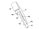
- the cam surface 15b formed in an inclined state with respect to the shaft as shown in FIGS.
- a top surface 15c is formed continuously from 15b, and both side edges 15d, 15e in the axial direction of the inner cylinder 15 left on the half circumferential surface are formed on the rotation stoppers 7f, 7g formed on the core case 7. It functions as a stopper mechanism that abuts and regulates the rotation range around the axis of the inner cylinder 15.
- FIG. 8 illustrates the operation of the stopper mechanism described above and the operation of the back-and-forth movement mechanism for setting the lead case 7 and the lead fixing chuck 8 to the forward or backward state.
- 8 shows a state in which the core case 7 is mounted in the inner cylinder 15, and
- FIG. 8A shows a state in which the core case 7 and the core fixing chuck 8 are retracted (FIGS. 1 and 3).
- (B) shows a state in which the lead case 7 and the lead fixing chuck 8 have moved forward (states in FIGS. 2 and 4).
- the core case 7 shows only a portion where the diameter of the latter half is slightly thick.
- the inclined surface 7e formed on the core case 7 is formed on the inner cylinder (cam forming member) 15 by the action of the chuck spring 12 shown in FIGS. Abutted against the cam surface 15b.
- the inner cylinder 15 is urged in the clockwise direction so that one rotation formed in the core case 7 is performed.
- the stopper 7g abuts on one side edge 15d formed on the inner cylinder 15, and the inner cylinder 15 functions as a stopper mechanism in which further rotation in the right direction is restricted.
- the lead case 7 and the lead fixing chuck 8 are in the retracted state, and the writing lead replenishment window 1 a formed on the side surface of the shaft tube 1 is covered by the clip member 17.
- the writing core replenishment window 1 a formed on the side surface of the shaft cylinder 1 is closed on the inside by the inner cylinder 15, and the writing core replenishing port is closed.
- the tip of the lead fixing chuck 8 is accommodated in the ring-shaped fastener 9, and the lead fixing chuck 8 is in a state of gripping the writing lead.
- FIG. 8B shows a state in which the ring-shaped operation portion 16 or the clip member 17 integrally formed therewith is rotated counterclockwise in the state shown in FIG. 8A. That is, when the ring-shaped operation portion 16 or the clip member 17 is rotated counterclockwise in the state shown in FIG. 8A, the cam surface 15 b formed on the inner cylinder 15 is inclined surface 7 e formed on the core case 7. Acts to push forward.
- the orthogonal surface 7d formed on the core case 7 rides on the top surface 15c formed on the inner cylinder 15 as shown in FIG. . Then, the other side edge 15e formed on the inner cylinder 15 abuts on the other rotation stopper 7f formed on the core case 7, and the inner cylinder 15 is a stopper in which further rotation in the left direction is restricted.
- the mechanism works.
- the rotation range of the inner cylinder 15 from FIG. 8A to FIG. 8B is set to about 90 degrees.
- the writing core replenishment window 1a formed on the side surface of the shaft cylinder 1 as shown in FIG. 2 is not covered by the clip member 17, and the shaft cylinder is not covered.
- the replenishment window 15a formed on the inner cylinder 15 and the replenishment window 7a formed on the core case 7 are in communication with the replenishment window 1a formed on the side surface of the writing core 1a. 18 is opened. Therefore, as shown in FIG. 2, the writing core L can be introduced from the supply port 18 which is long in the opened axial direction.
- the lead case 7 and the lead fixing chuck 8 are moved forward, and the tip of the lead fixing chuck 8 protrudes from the ring-shaped fastener 9 and is written.
- the core is released from gripping. Accordingly, the writing lead L supplied into the lead case 7 passes through the lead fixing chuck 8, and its tip immediately reaches (holds down) the position of the holding chuck 5 arranged in the immediate vicinity of the lead feeding opening of the tip pipe 4. ) The tip of the writing core L thus replenished is held in a state immediately before feeding by the holding chuck 5 in the tip pipe 4.
- the writing core L is sequentially fed out from the lead feeding port of the tip pipe 4 by returning the above-described operation portion 16 or the clip member 17 to the state shown in FIG. 8A and knocking the above-described knock cover 14. Act to be
- the tip of the replenished writing core L reaches the position of the holding chuck 5 arranged in the immediate vicinity of the core feeding opening of the tip pipe 4. Reach instantly. Therefore, by knocking the knock cover 14 about once or twice, the leading end of the writing core L is immediately fed out from the tip pipe 4 by the feeding operation of the writing core L by the core fixing chuck 8 and the holding chuck 5. You will be able to write.
- FIGS. 9 to 14 show a second embodiment of the mechanical pencil according to the present invention.
- FIG. 9 and FIG. 10 show the overall configuration of the second embodiment, and parts that perform the same functions as the parts shown in FIG. 1 and FIG. Therefore, the detailed description is abbreviate
- the cam forming member 15 that functions as an inner cylinder in the first embodiment is omitted, and in the second embodiment, the core case 7 also serves as the inner cylinder.
- the core case 7 as the middle cylinder is rotated by rotating the operation unit 16. Accordingly, the replenishment window 1a formed in the shaft cylinder 1 and the replenishment window 7a formed in the lead case 7 are not communicated with each other, and the replenishment window 1a is closed as shown in FIG. , 7a are connected to each other, and the state shown in FIG.
- the writing core replenishing window 1 a formed on the side surface of the shaft tube 1 is covered with the clip member 17 as in the first embodiment.
- the writing core replenishment window 1 a formed on the side surface of the shaft tube 1 is covered with the clip member 17 as in the first embodiment.
- the writing lead L can be supplied into the lead case 7 from the supply port 18 that is long in the axial direction.
- the lead case 7 and the lead fixing chuck 8 can be moved forward by rotating the operation portion 16. Instead, in this embodiment, by knocking the knock cover 14, the core fixing chuck 8 moves forward together with the core case 7, and the tip portion thereof operates to protrude from the fastener 9.
- the lead fixing chuck 8 together with the lead case 7 is retracted by the action of the chuck spring 12, and the tip of the lead fixing chuck is accommodated in the fastener 9, which is the same as a normal knock type mechanical pencil. Is performed. That is, by repeating the knocking operation, the writing core held by the core fixing chuck 8 acts so as to be sequentially fed out from the tip pipe 4.
- FIG. 11 shows the configuration of the shaft cylinder 1 used in the second embodiment.
- FIG. 11A is a cross-sectional view taken along the replenishment window 1a
- FIG. 11B is an enlarged perspective view of the rear end portion of the shaft tube 1.
- FIG. An annular step portion 1e is formed inside the opening at the rear end portion of the shaft tube 1, and the projecting portion 1f protrudes from the annular step portion 1e at an interval of about 90 degrees by axial rotation. Is formed.
- this convex portion functions as a stopper mechanism that regulates the rotational range around the axis of the inner cylinder (core case) 7 with respect to the shaft cylinder 1.
- a small protrusion 1g protruding in an arc shape is formed adjacent to the inside of each protrusion 1f in the range of 90 degrees formed in the annular step 1e, which will be described with reference to FIG. As described above, it is provided to give a click feeling to the turning operation of the operation unit 16.
- FIG. 12 shows the configuration of the core case 7 as an inner cylinder.
- the rear half portion of the core case 7 is formed with a slightly thicker diameter, and a replenishment window 7a with a long writing core is formed in the axial direction. Yes.
- a groove 7h that is long in the axial direction is formed in the rear half portion that is formed to have a slightly thicker diameter so as to avoid the formation position of the replenishment window 7a, and this groove 7h is approximately 90 around the axis of the core case 7. Arranged at intervals of degrees.
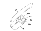
- FIG. 13 is an enlarged view of the operation portion 16 with the clip 17 attached to the rear end portion of the core case 7, and the inner diameter portion of the annular operation portion 16 protrudes with an interval of 90 degrees.
- the rib 16a is shaped in a state protruding in the axial direction.
- a hemispherical protrusion 16b is formed at a position facing the front end edge of the operation unit 16 at 180 degrees.
- the operation unit 16 is disposed on the rear end side of the core case 7. That is, when the convex rib 16a of the operation unit 16 is inserted into the groove 7h of the core case 7, the core case 7 slides in the axial direction with respect to the operation unit 16, and the axial direction of the operation unit 16 It acts so that the rotational movement is transmitted to the lead case 7.
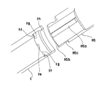
- FIG. 14 shows the relationship between the shaft cylinder 1 and the operation section 16 rotatably attached to the rear end portion of the shaft cylinder 1.
- the shaft cylinder 1 and the operation section 16 are shown.
- a part of each circumferential direction is shown by removing the front side.
- An annular projecting portion 1h projecting in the inner circumferential direction is formed at the rear end portion of the shaft tube 1, and an annular groove portion 16c formed in the operation portion 16 enters the annular projecting portion 1h.
- the operation unit 16 is rotatably attached to the shaft tube 1.
- the hemispherical protrusion 16 b formed on the operation portion 16 is in contact with an annular step portion 1 e formed on the shaft tube 1. Therefore, by rotating the operation portion 16 with respect to the shaft cylinder 1, the hemispherical protrusion 16b on the operation portion 16 side acts so as to slide on the annular step portion 1e on the shaft tube 1 side. . Further, the hemispherical projection 16b on the operation unit 16 side comes into contact with the convex portion 1f on the shaft tube 1 side, so that the rotation of the operation unit 16 is restricted. Therefore, in this embodiment, the shaft The operating portion 16 rotates with respect to the cylinder 1 as a topper mechanism having a rotation range of 90 degrees.
- the arc-shaped small protrusion 1g is formed adjacent to the convex portion 1f formed on the shaft tube 1, the hemispherical protrusion 16b formed on the operation portion 16 is rotated by the operation portion 16. In response to the operation, it acts to get over the small protrusion 1g and contact the convex portion 1f on the shaft tube 1 side. Thereby, a click feeling can be given to the rotation operation of the operation unit 16 at the end of the 90-degree rotation range of the operation unit 16.
- the clip member 17 is integrally formed on the operation portion 16 that rotates the inner cylinder (the core case 7 and the cam forming member 15).
- the clip member 17 is not always necessary, and an operation portion in which an annular outer peripheral surface is provided with striped irregularities in the axial direction can be suitably employed.
Landscapes
- Mechanical Pencils And Projecting And Retracting Systems Therefor, And Multi-System Writing Instruments (AREA)
Abstract
筆記芯の補給時における操作性を向上させることができると共に、デザイン上においても優れたシャープペンシルを提供する。外郭を構成する軸筒1と、当該軸筒内に軸回りに回動可能に収容されたカム形成部材15による内筒と、前記内筒を回動させることができる操作部16とが具備されている。前記軸筒1および前記内筒15の側面に、軸方向に長い筆記芯の補給窓1a,15aがそれぞれ形成されると共に、前記操作部16の操作による前記軸筒に対する前記内筒の特定な回動位置において、前記各補給窓1a,15aが連通するように構成され、連通した各補給窓により筆記芯の補給口18が開口される。
Description
この発明は、筆記芯(替え芯)を容易に補給することができるシャープペンシルに関する。
例えばノック式のシャープペンシルは、軸筒の後端部にノックカバーが着脱可能に取り付けられており、このノックカバーを軸方向にノック操作することで、軸筒内の芯ケースに収容された筆記芯(替え芯)が、芯固定チャックと保持チャックの作用により、軸筒先端側の口先部から順次繰り出されるように作用する。
そして、前記筆記芯を補給する場合には、前記ノックカバーを取り外すと共に、このノックカバー内に収容されている消しゴムも取り外し、芯ケース後端部の補給口に筆記芯を補給する操作がなされる。
この筆記芯の補給に際しては、シャープペンシルの軸筒を片手に持ち、他方の手で補給する筆記芯を持つことになるために、取り外した前記ノックカバーや消しゴムは一旦机上等に置くことになる。したがって、ノックカバーや消しゴムが机上等から転げ落ちるという問題をしばしば経験するところであり、時には前記ノックカバー等を紛失するなどの問題も招く。
この筆記芯の補給に際しては、シャープペンシルの軸筒を片手に持ち、他方の手で補給する筆記芯を持つことになるために、取り外した前記ノックカバーや消しゴムは一旦机上等に置くことになる。したがって、ノックカバーや消しゴムが机上等から転げ落ちるという問題をしばしば経験するところであり、時には前記ノックカバー等を紛失するなどの問題も招く。
そこで、筆記芯を補給するに際して、前記したノックカバーや消しゴムの取り外しの操作を不要としたシャープペンシルについて提案がなされており、これは特許文献1に開示されている。
ところで、前記特許文献には二つのシャープペンシルの形態が開示されており、その第1の構成は、軸筒に対してクリップ部材を支軸によって回動可能に取り付けると共に、前記支軸にばね部材が捲装され、前記クリップ部材の前端部が前記ばね部材によって軸筒の外側面に圧着される構成が採用されている。
そして、軸筒の側面に軸方向に長い筆記芯の補給窓が形成され、この補給窓を覆う開閉蓋が、前記支軸およびばね部材によって常時閉じた状態を維持するように取り付けられている。
そして、軸筒の側面に軸方向に長い筆記芯の補給窓が形成され、この補給窓を覆う開閉蓋が、前記支軸およびばね部材によって常時閉じた状態を維持するように取り付けられている。
前記した第1の構成のシャープペンシルによると、支軸に対してクリップ部材および補給窓の開閉蓋が共に取り付けられ、しかもばね部材によってクリップ部材および開閉蓋を閉じる方向に付勢する構成であるために、前記支軸およびばね部材付近の構造が複雑化し、その組み立てに格別な工夫が必要になる。
また、筆記芯を補給する際には、片手でシャープペンシルの軸筒を把持し、他方の手でばね部材により閉じる方向に付勢されている前記開閉蓋を開ける操作をしなければならない。したがって、筆記芯を前記補給窓に挿入する操作が容易ではなく、操作性に欠けるという問題が残される。
また、筆記芯を補給する際には、片手でシャープペンシルの軸筒を把持し、他方の手でばね部材により閉じる方向に付勢されている前記開閉蓋を開ける操作をしなければならない。したがって、筆記芯を前記補給窓に挿入する操作が容易ではなく、操作性に欠けるという問題が残される。
一方、前記特許文献に開示された第2の構成のシャープペンシルは、軸筒本体の後半部を覆うキャップ部材が、前記軸筒本体に回転可能に装着された構成が採用されている。そして、キャップ部材の周側面に軸方向に長い筆記芯の補給窓が施され、その内側の軸筒本体側にも軸方向に長い補給窓が施されている。
これにより、前記キャップ部材を軸方向に回動させることで、キャップ部材と軸筒本体にそれぞれ形成された筆記芯補給窓を一致させることができ、この状態で筆記芯を芯ケース内に補給することができる。
これにより、前記キャップ部材を軸方向に回動させることで、キャップ部材と軸筒本体にそれぞれ形成された筆記芯補給窓を一致させることができ、この状態で筆記芯を芯ケース内に補給することができる。
前記した第2の構成のシャープペンシルによると、軸筒本体の後半部を覆うキャップ部材を回動させることで、筆記芯の補給窓を開閉させるように機能するので、前記特許文献に示されているようにキャップ部材にクリップを一体に取り付けた構成を採用した場合においては、クリップと筆記芯の補給窓とは、周方向において位置をずらして配置する必要がある。
このために、筆記芯の補給窓はクリップの配置位置とは異なるキャップ部材の一部に常に露出した状態になされ、体裁が悪くデザイン上において工夫が望まれることになる。
このために、筆記芯の補給窓はクリップの配置位置とは異なるキャップ部材の一部に常に露出した状態になされ、体裁が悪くデザイン上において工夫が望まれることになる。
また、第2の構成のシャープペンシルによると、軸筒本体の後半部を覆うキャップ部材を回動させる構成であるために、キャップ部材を回動操作するに際して、把持する位置が限られる。このためにシャープペンシルを片手で持ちつつキャップ部材を回動させるような操作(片手回し)がし難く、これにより筆記芯の補給時における操作上の難点も抱えることになる。
この発明は、従来のシャープペンシルにおける前記した問題点を解消するためになされたものであり、操作部の操作により軸筒内に収容された内筒を軸回りに回動させて、筆記芯の補給口が開閉されるように構成し、これにより、筆記芯の補給時における操作性を向上させることができると共に、デザイン上においても優れたシャープペンシルを提供することを課題とするものである。
前記した課題を解決するためになされたこの発明に係るシャープペンシルは、外郭を構成する軸筒と、当該軸筒内に軸回りに回動可能に収容された内筒と、前記内筒を回動させることができる操作部とが具備され、前記軸筒および前記内筒の側面に、軸方向に長い筆記芯の補給窓がそれぞれ形成されると共に、前記操作部の操作による前記軸筒に対する前記内筒の特定な回動位置において前記各補給窓が連通するように構成され、連通した各補給窓により筆記芯の補給口が開口されるように構成したことを特徴とする。
この場合、前記内筒を回動させることができる操作部にはクリップ部材が配置された構成を好適に採用することができ、前記軸筒の側面に形成された筆記芯の補給窓が前記クリップ部材によって覆われた状態で前記筆記芯の補給口が閉塞され、前記軸筒の側面に形成された筆記芯の補給窓が前記クリップ部材によって覆われない状態で前記筆記芯の補給口が開口されるように構成することが望ましい。
そして、この発明に係るシャープペンシルの一つの好ましい形態においては、前記内筒は、その内側に芯ケースを配置したカム形成部材により構成され、前記カム形成部材には、前記操作部の操作により筆記芯の補給口が開口された状態において、前記芯ケースを前進状態に保持するカム面が形成され、前記芯ケースの前進状態において、前記芯ケースの前端部に取り付けられた芯固定チャックによる筆記芯の把持が解除されるように構成されると共に、前記筆記芯を摩擦により保持する保持チャックが、前記筆記芯の繰り出し口の直近に配置された構成が採用される。
また、この発明に係るシャープペンシルの他の一つの好ましい形態においては、前記内筒は芯ケースであり、当該芯ケースの前端部に芯固定チャックが取り付けられ、ノック操作部のノック操作により前記芯ケースを介して芯固定チャックが軸方向に移動可能に構成され、前記芯固定チャックの軸方向の移動に基づいて、芯ケース内の筆記芯を軸筒の先端部より順次繰り出すことができるように構成される。
そして、前記軸筒に対する前記内筒の軸回りの回動範囲を規制するストッパー機構が具備されることが望ましく、その一つの形態においては、前記ストッパー機構により前記内筒の軸回りの回動が規制された位置で、前記筆記芯の補給口が開口されるように構成される。また、他の一つの形態においては、前記ストッパー機構により前記内筒の軸回りの回動が規制された位置で、前記軸筒の側面に形成された筆記芯の補給窓が前記クリップ部材によって覆われた状態になされる。
前記したこの発明に係るシャープペンシルによると、外郭を構成する軸筒内に軸回りに回動可能に内筒が収容され、操作部の操作により前記内筒を回動させることで、軸筒の側面に形成された筆記芯の補給口が開閉するようになされる。
したがって、シャープペンシルの外郭を構成する軸筒を把持しつつ、前記操作部を指先等で操作することが容易であり、これにより前記した片手回しの操作により、筆記芯の補給口の開閉操作を行うことが容易となる。
それ故、他方の手で筆記芯を持ち、当該筆記芯を前記補給口に投入することができるので、筆記芯の補給時における操作性を格段に向上させることができる。
したがって、シャープペンシルの外郭を構成する軸筒を把持しつつ、前記操作部を指先等で操作することが容易であり、これにより前記した片手回しの操作により、筆記芯の補給口の開閉操作を行うことが容易となる。
それ故、他方の手で筆記芯を持ち、当該筆記芯を前記補給口に投入することができるので、筆記芯の補給時における操作性を格段に向上させることができる。
また、前記操作部にクリップ部材を取り付けた構成を採用した場合には、軸筒の側面に形成された軸方向に長い筆記芯の補給窓を、前記クリップ部材によって覆うことができる。この場合、前記筆記芯の補給口が閉塞された状態において、前記クリップ部材が補給窓に対峙するように構成することで、筆記芯の補給時以外の常時においては、筆記芯の補給窓を前記クリップ部材によって隠すことができる。
これにより、常時において前記補給窓が露出することのない体裁の整ったシャープペンシルを提供することが可能となる。
これにより、常時において前記補給窓が露出することのない体裁の整ったシャープペンシルを提供することが可能となる。
以下、この発明に係るシャープペンシルについて、図に示す実施の形態に基づいて説明する。なお、以下に示す各図においては、同一部分もしくは同一の機能を果たす部分を同一符号で示しているが、紙面の都合により一部の図面においては、代表的な部分に符号を付け、その詳細な構成はその他の図面に付けた符号を引用して説明する場合もある。
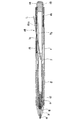
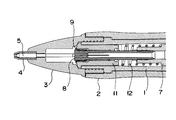
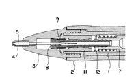
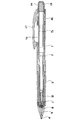
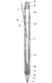
先ず図1~図8は、この発明に係るシャープペンシルの第1の形態を示したものである。図1および図2において、符号1はその外郭を構成する軸筒を示しており、この軸筒1の前端部側には、軸筒1を捲装するようにしてグリップゴム2が装着されている。また、前記軸筒1の先端部には、図3および図4にも示されているように口先部材(クチプラ)3がねじ込みにより取り付けられており、この口先部材3の先端部には、先端パイプ4が突出した状態で装着されている。
加えて、前記先端パイプ4における芯繰り出し口直近の内周面には、中央に通孔が形成され、筆記芯を摩擦により保持することができるゴム製の保持チャック5(図3、図4参照)が収容されている。
加えて、前記先端パイプ4における芯繰り出し口直近の内周面には、中央に通孔が形成され、筆記芯を摩擦により保持することができるゴム製の保持チャック5(図3、図4参照)が収容されている。
前記軸筒1内には芯ケース7が軸筒1と同軸状に収容されており、この芯ケース7の先端部には芯固定チャック8が連結されている。この芯固定チャック8には、その軸芯に沿って通孔が形成され、真ちゅうにより形成された先端部が複数に分割されて、分割された先端部の周囲が、同じく真ちゅうによりリング状に形成された締め具9(図3、図4参照)内に遊嵌するようにして装着されている。
前記芯固定チャック8は、その周囲を覆う円筒状にして短軸状に形成された継手部材11内に、軸方向に摺動可能に装着されており、前記継手部材11の外周面は前記軸筒1の前端部における内周面に嵌合されて取り付けられている。
前記芯固定チャック8は、その周囲を覆う円筒状にして短軸状に形成された継手部材11内に、軸方向に摺動可能に装着されており、前記継手部材11の外周面は前記軸筒1の前端部における内周面に嵌合されて取り付けられている。
また、前記した継手部材11と芯ケース7との間には、コイル状のチャックスプリング12が配置されている。すなわち、前記チャックスプリング12の後端部は前記芯ケース7の前端部付近に形成された段部に当接され、また前記チャックスプリング12の前端部は前記継手部材11の後端部に当接している。
したがって、前記チャックスプリング12の作用により、前記芯ケース7および芯固定チャック8は軸方向に後退する方向に付勢され、芯固定チャック8の先端部が前記締め具9内に収容されることで、筆記芯は芯固定チャック8の通孔内において把持された状態になされる。
したがって、前記チャックスプリング12の作用により、前記芯ケース7および芯固定チャック8は軸方向に後退する方向に付勢され、芯固定チャック8の先端部が前記締め具9内に収容されることで、筆記芯は芯固定チャック8の通孔内において把持された状態になされる。
一方、前記芯ケース7の後半部は径が若干太く形成されており、その後端部の開口には、消しゴム13が着脱可能に装着されている。また前記消しゴム13を覆うノックカバー14が前記芯ケース7の後端部周面に着脱可能に取り付けられている。また前記軸筒1の後半部において、軸筒1と芯ケース7との間には、前記軸筒1に対して軸回りに回動可能になされた内筒として機能するカム形成部材15が配置されている。
なお、前記内筒としてのカム形成部材15の一部は、前記軸筒1の後端部に突出してリング状の操作部16を構成しており、この実施の形態においては、前記操作部16の一部にクリップ部材17の根元部分が一体に成形されている。
したがって、前記クリップ部材17もしくは前記操作部16を、回動操作することで、内筒としてのカム形成部材15は、前記したとおり軸筒1内を軸回りに回動することになる。
したがって、前記クリップ部材17もしくは前記操作部16を、回動操作することで、内筒としてのカム形成部材15は、前記したとおり軸筒1内を軸回りに回動することになる。
図1および図2に示されているように前記軸筒1の側面には、軸方向に長い筆記芯の補給窓1aが形成されており、また内筒としてのカム形成部材15の側面にも、軸方向に長い筆記芯の補給窓15aが形成されている。さらに前記芯ケース7にも軸方向に長い筆記芯の補給窓7aが形成されている。
したがって図2に示したように、前記軸筒1に対する前記カム形成部材15の特定な回動位置において、前記各補給窓1a,15a,7aが連通し、これにより筆記芯の補給口18が開口される。それ故、開口された筆記芯の補給口18を利用して、図2に示したように筆記芯Lを芯ケース7内に補給することができる。
なお、図に示す実施の形態においては、前記した芯ケース7の後端部からノックカバー14および消しゴム13を取り外すことによっても、芯ケース7内に筆記芯Lを補給することができる。
なお、図に示す実施の形態においては、前記した芯ケース7の後端部からノックカバー14および消しゴム13を取り外すことによっても、芯ケース7内に筆記芯Lを補給することができる。
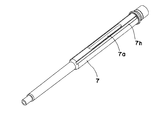
図5は、前記した芯ケース7の単体構成を示したものであり、(a)は前記した補給窓7aを上にした状態の斜視図であり、(b)は(a)の状態に対して軸方向にほぼ半回転させた状態の斜視図で示している。また(c)は(b)に示す面を上にした平面図で示している。
この芯ケース7の径が若干太く形成された後半部には、前記したとおり軸方向に長い筆記芯の補給窓7aが形成されており、この補給窓7aが形成された芯ケースの背面側には肉厚部7bが突出形成されている。
この芯ケース7の径が若干太く形成された後半部には、前記したとおり軸方向に長い筆記芯の補給窓7aが形成されており、この補給窓7aが形成された芯ケースの背面側には肉厚部7bが突出形成されている。
この肉厚部7bには軸方向に長いガイド部材7c、軸に直交する方向に形成された直交面7d、この直交面7dに周方向に連続して傾斜面7eが形成されている。
さらに前記肉厚部7bにおける軸方向に沿った両側縁7f,7gは、後述するクリップ付の内筒(カム形成部材)15の一部が当接することで、内筒15の軸回りの回動範囲を規制する回転ストッパーとして機能する。
さらに前記肉厚部7bにおける軸方向に沿った両側縁7f,7gは、後述するクリップ付の内筒(カム形成部材)15の一部が当接することで、内筒15の軸回りの回動範囲を規制する回転ストッパーとして機能する。
次に図6は、前記した軸筒1の単体構成を示したものであり、(a)は前記した補給窓1aを上にした状態の斜視図であり、(b)は前記補給窓1a側の半周面を除いた状態の断面図で示している。
前記軸筒1における補給窓1aが形成された位置の裏側の内周面には、図6(b)に示したように2本のリブ部材1b,1cが、軸方向に平行状態で内面に突出した状態で形成されている。前記2本のリブ部材1b,1cによって、その間に実質的に軸方向に長い縦溝1dが形成されている。
前記軸筒1における補給窓1aが形成された位置の裏側の内周面には、図6(b)に示したように2本のリブ部材1b,1cが、軸方向に平行状態で内面に突出した状態で形成されている。前記2本のリブ部材1b,1cによって、その間に実質的に軸方向に長い縦溝1dが形成されている。
したがって、前記軸筒1内に前記芯ケース7を挿入した組み立て状態においては、芯ケース7に形成された軸方向に長い前記したガイド部材7cが、軸筒1内に形成された前記2本のリブ部材1b,1cの間の縦溝1d内に入り、芯ケース7は軸筒1内において軸方向に摺動し、軸回転が規制された状態になされる。
加えてこの状態において、図1および図2に示したように軸筒1および芯ケース7にそれぞれ形成された軸方向に長い筆記芯の補給窓1a,7aの位置が一致するように構成される。
加えてこの状態において、図1および図2に示したように軸筒1および芯ケース7にそれぞれ形成された軸方向に長い筆記芯の補給窓1a,7aの位置が一致するように構成される。
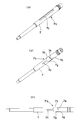
図7A~図7Cはクリップ付の内筒(カム形成部材)15を示した斜視図であり、図7Aは前記した補給窓15aが前側に位置する状態の斜視図であり、図7Bおよび図7Cは、図7Aの状態からさらにそれぞれ90度軸回転させた場合の斜視図で示している。
前記したとおり、前記内筒(カム形成部材)15は、その後端部がリング状の操作部16になされ、この操作部16にクリップ部材17が一体に成形されている。
また、内筒15は円筒体を軸方向で半分に割った状態で構成されており、残された半周面の一部に、前記した軸方向に長い筆記芯の補給窓15aが形成されている。
前記したとおり、前記内筒(カム形成部材)15は、その後端部がリング状の操作部16になされ、この操作部16にクリップ部材17が一体に成形されている。
また、内筒15は円筒体を軸方向で半分に割った状態で構成されており、残された半周面の一部に、前記した軸方向に長い筆記芯の補給窓15aが形成されている。
前記内筒15における前記操作部16の直近部分における円筒部の端面には、図7Bおよび図7Cに示されたように、軸に対して傾斜状態に形成されたカム面15bと、このカム面15bに連続して頂面15cが形成されており、また半周面で残された内筒15の軸方向の両側縁15d,15eは、前記した芯ケース7に形成された回転ストッパー7f,7gに当接して、内筒15の軸回りの回動範囲を規制するストッパー機構として機能する。
図8は、前記したストッパー機構の動作、および前記した芯ケース7と芯固定チャック8を前進もしくは後退状態に設定する前後移動機構の動作について説明するものである。
すなわち図8は、前記した内筒15内に前記した芯ケース7を装着した状態で示したものであり、(a)は芯ケース7ならびに芯固定チャッ8が後退した状態(図1、図3の状態)を示しており、(b)は芯ケース7ならびに芯固定チャッ8が前進した状態(図2、図4の状態)を示している。
なお図8においては、芯ケース7はその後半部の径が若干太く形成された部分のみを図示している。
すなわち図8は、前記した内筒15内に前記した芯ケース7を装着した状態で示したものであり、(a)は芯ケース7ならびに芯固定チャッ8が後退した状態(図1、図3の状態)を示しており、(b)は芯ケース7ならびに芯固定チャッ8が前進した状態(図2、図4の状態)を示している。
なお図8においては、芯ケース7はその後半部の径が若干太く形成された部分のみを図示している。
図8(a)に示す状態においては、芯ケース7に形成された前記傾斜面7eは、図1~図4に示したチャックスプリング12の作用により、内筒(カム形成部材)15に形成されたカム面15bに当接している。
前記芯ケース7の傾斜面7eが前記内筒15のカム面15bに当接することにより、前記内筒15は右回転される方向に付勢され、これにより芯ケース7に形成された一方の回転ストッパー7gは、内筒15に形成された一方の側縁15dに当接し、内筒15はこれ以上の右方向への回動が規制されるストッパー機構が機能する。
前記芯ケース7の傾斜面7eが前記内筒15のカム面15bに当接することにより、前記内筒15は右回転される方向に付勢され、これにより芯ケース7に形成された一方の回転ストッパー7gは、内筒15に形成された一方の側縁15dに当接し、内筒15はこれ以上の右方向への回動が規制されるストッパー機構が機能する。
この状態においては、図1に示されたように芯ケース7および芯固定チャック8は後退状態となり、前記軸筒1の側面に形成された筆記芯の補給窓1aが、前記クリップ部材17によって覆われた状態になされる。さらにこの状態においては、軸筒1の側面に形成された筆記芯の補給窓1aは、前記内筒15によって内側で閉じられ、筆記芯の補給口は閉塞される。
またこの状態においては、図3に示すように芯固定チャック8の先端部は、リング状の締め具9内に収容され、芯固定チャック8は筆記芯を把持した状態になされる。
またこの状態においては、図3に示すように芯固定チャック8の先端部は、リング状の締め具9内に収容され、芯固定チャック8は筆記芯を把持した状態になされる。
図8(b)は、前記した図8(a)に示す状態において、リング状の操作部16もしくはこれに一体成形されたクリップ部材17を左回転させた状態を示している。
すなわち、図8(a)に示す状態においてリング状の操作部16もしくはクリップ部材17を左回転させると、前記内筒15に形成されたカム面15bが、芯ケース7に形成された傾斜面7eを前方に押し出すように作用する。
すなわち、図8(a)に示す状態においてリング状の操作部16もしくはクリップ部材17を左回転させると、前記内筒15に形成されたカム面15bが、芯ケース7に形成された傾斜面7eを前方に押し出すように作用する。
前記操作部16もしくはクリップ部材17をなおも左回転させると、図8(b)に示すように芯ケース7に形成された直交面7dが、前記内筒15に形成された頂面15cに乗り上げる。
そして、内筒15に形成された他方の側縁15eが、芯ケース7に形成された他方の回転ストッパー7fに当接し、内筒15はこれ以上の左方向への回動が規制されるストッパー機構が機能する。
なお、この実施の形態においては、図8(a)から図8(b)に至る前記内筒15の回動範囲は、90度程度に設定されている。
そして、内筒15に形成された他方の側縁15eが、芯ケース7に形成された他方の回転ストッパー7fに当接し、内筒15はこれ以上の左方向への回動が規制されるストッパー機構が機能する。
なお、この実施の形態においては、図8(a)から図8(b)に至る前記内筒15の回動範囲は、90度程度に設定されている。
図8(b)に示す状態においては、図2に示されたように軸筒1の側面に形成された筆記芯の補給窓1aは、前記クリップ部材17によって覆われることはなく、また軸筒1の側面に形成された筆記芯の補給窓1aに、内筒15に形成された補給窓15aおよび芯ケース7に形成された補給窓7aが一致して連通し、これにより筆記芯の補給口18が開口された状態になされる。したがって図2に示すように、開口された軸方向に長い補給口18から筆記芯Lを投入することができる。
また、この状態においては、図2および図4に示されたように芯ケース7および芯固定チャック8は前進状態となり、芯固定チャック8の先端部は、リング状の締め具9から突出して筆記芯の把持が解除された状態になされる。
したがって、芯ケース7内に補給された筆記芯Lは、芯固定チャック8を通り抜け、その先端部は先端パイプ4の芯繰り出し口の直近に配置された保持チャック5の位置まで即座に到達(落下)する。これにより補給された筆記芯Lの先端部は、前記先端パイプ4内の保持チャック5により、繰り出し直前の状態に保持される。
したがって、芯ケース7内に補給された筆記芯Lは、芯固定チャック8を通り抜け、その先端部は先端パイプ4の芯繰り出し口の直近に配置された保持チャック5の位置まで即座に到達(落下)する。これにより補給された筆記芯Lの先端部は、前記先端パイプ4内の保持チャック5により、繰り出し直前の状態に保持される。
そこで、前記した操作部16もしくはクリップ部材17を、図8(a)に示す状態に戻し、前記したノックカバー14をノック操作することにより、筆記芯Lは先端パイプ4の芯繰り出し口より順次繰り出されるように作用する。
以上説明した図1~図8に示す第1の形態のシャープペンシルによると、補給された筆記芯Lの先端部は、先端パイプ4の芯繰り出し口の直近に配置された保持チャック5の位置まで即座に到達する。したがって、ノックカバー14を1~2回程度ノック操作をすることにより、芯固定チャック8および保持チャック5による筆記芯Lの繰り出し動作により、筆記芯Lの先端部は先端パイプ4より直ちに繰り出され、筆記が可能な状態となる。
前記した第1の形態によると、筆記芯の補給時における操作性を向上させることができるなど、前記した発明の効果の欄に記載した独自の作用効果に加え、補給した筆記芯を繰り出すために数多く必要としたノック操作の繰り返しを不要にすることができるなどの独自の効果を得ることもできる。
次に図9~図14は、この発明に係るシャープペンシルの第2の形態を示したものである。図9および図10は第2の形態の全体構成を示したものであり、すでに説明した図1および図2に示す各部と同一の機能を果たす部分を同一符号で示している。したがって、その詳細な説明は適宜省略する。
第2の形態においては、第1の形態において内筒として機能するカム形成部材15は除かれており、この第2の形態においては前記中筒は芯ケース7が兼ねている。
第2の形態においては、第1の形態において内筒として機能するカム形成部材15は除かれており、この第2の形態においては前記中筒は芯ケース7が兼ねている。
すなわち、操作部16を回動操作することで、中筒としての芯ケース7が回動されるように構成されている。これにり、軸筒1に形成された補給窓1a、芯ケース7に形成された補給窓7aが連通せずに筆記芯の補給口が閉塞された図9に示す状態、また前記補給窓1a,7aが連通して筆記芯の補給口18が開口された図10に示す状態が選択される。
また、筆記芯の補給口が閉塞された図9に示す状態においては、第1の形態と同様に軸筒1の側面に形成された筆記芯の補給窓1aが、クリップ部材17によって覆われた状態になされる。そして、筆記芯の補給口18が開口された図10に示す状態においては、第1の形態と同様に軸筒1の側面に形成された筆記芯の補給窓1aは、クリップ部材17によって覆われず、この状態で軸方向に長い補給口18から筆記芯Lを芯ケース7内に補給することができる。
また、第2の形態においては、第1の形態におけるカム形成部材15は除かれているので、操作部16を回動操作することで、芯ケース7および芯固定チャック8が前進動作することはなく、この実施の形態においては、ノックカバー14をノック操作することにより、芯ケース7と共に芯固定チャック8が前進して、その先端部が前記締め具9から突出するように動作する。
そして、ノック操作の解除により芯ケース7と共に芯固定チャック8がチャックスプリング12の作用により後退して、芯固定チャックの先端部は締め具9内に収容され、通常のノック式のシャープペンシルと同様の動作がなされる。
すなわち、前記ノック操作の繰り返しにより、芯固定チャック8に把持されている筆記芯は、順次先端パイプ4から繰り出されるように作用する。
すなわち、前記ノック操作の繰り返しにより、芯固定チャック8に把持されている筆記芯は、順次先端パイプ4から繰り出されるように作用する。
図11は、第2の形態に用いられる軸筒1の構成を示している。図11(a)は補給窓1a部分で切断した断面図であり、図11(b)は軸筒1の後端部を拡大して示した斜視図である。
この軸筒1の後端部における開口内部には、円環状に段部1eが形成されており、この円環状の段部1eには、軸回転でほぼ90度を隔てて凸部1fが突出形成されている。この凸部は、後で図14に基づいて説明するとおり、軸筒1に対する内筒(芯ケース)7の軸回りの回動範囲を規制するストッパー機構として機能するものである。
この軸筒1の後端部における開口内部には、円環状に段部1eが形成されており、この円環状の段部1eには、軸回転でほぼ90度を隔てて凸部1fが突出形成されている。この凸部は、後で図14に基づいて説明するとおり、軸筒1に対する内筒(芯ケース)7の軸回りの回動範囲を規制するストッパー機構として機能するものである。
前記円環状の段部1eに形成された90度の範囲における各凸部1fの内側に隣接して、円弧状に突出する小突起1gが形成されており、これは図14に基づいて説明するとおり、操作部16の回動操作にクリック感を与えるために設けられている。
図12は、内筒としての芯ケース7の構成を示したものであり、この芯ケース7の後半部は径が若干太く形成されて、軸方向に長い筆記芯の補給窓7aが形成されている。また径が若干太く形成された後半部には、前記補給窓7aの形成位置を避けるようにして軸方向に長い溝7hが形成されており、この溝7hは芯ケース7の軸回りにほぼ90度の間隔をもって配置されている。
図13は、前記芯ケース7の後端部に装着されるクリップ17付き操作部16を拡大して示したものであり、円環状の操作部16の内径部には、90度の間隔をもって凸状のリブ16aが軸方向に突出した状態で成形されている。また、操作部16の前端縁における180度対向する位置には、半球状の突起16bが形成されている。
この図13に示すクリップ17付き操作部16は、その後端部の開口に図12に示した芯ケース7の前端部に挿入され、操作部16に形成された前記凸状のリブ16aが、芯ケース7の溝7hに挿入されることで、操作部16は芯ケース7の後端部側に配置される。
すなわち、操作部16の凸状のリブ16aが、芯ケース7の溝7hに挿入されることで、操作部16に対して芯ケース7は軸方向に摺動し、操作部16の軸方向の回動動作が芯ケース7に伝達されるように作用する。
すなわち、操作部16の凸状のリブ16aが、芯ケース7の溝7hに挿入されることで、操作部16に対して芯ケース7は軸方向に摺動し、操作部16の軸方向の回動動作が芯ケース7に伝達されるように作用する。
図14は、前記した軸筒1と、この軸筒1の後端部に回動可能に取り付けられた操作部16との関係を示すものであり、図14においては軸筒1および操作部16の前面側を削除してそれぞれの周方向の一部を示している。
前記軸筒1の後端部には、内周方向に突出する環状突出部1hが形成されており、この環状突出部1hに対して、前記操作部16に形成された環状の溝部16cが入り込むことで、前記軸筒1に対して前記操作部16が回動可能に装着されている。
前記軸筒1の後端部には、内周方向に突出する環状突出部1hが形成されており、この環状突出部1hに対して、前記操作部16に形成された環状の溝部16cが入り込むことで、前記軸筒1に対して前記操作部16が回動可能に装着されている。
そして、操作部16に形成された前記半球状突起16bが、軸筒1に形成された円環状の段部1eに当接した状態になされている。したがって、軸筒1に対して操作部16を回動操作することで、操作部16側の半球状突起16bは、軸筒1側の円環状段部1eの上を摺動するように作用する。
また、操作部16側の半球状突起16bが、軸筒1側の凸部1fに当接することで、操作部16の回動が規制されようになされ、したがって、この実施の形態においては、軸筒1に対する操作部16の回動範囲は90度となるトッパー機構として動作する。
また、操作部16側の半球状突起16bが、軸筒1側の凸部1fに当接することで、操作部16の回動が規制されようになされ、したがって、この実施の形態においては、軸筒1に対する操作部16の回動範囲は90度となるトッパー機構として動作する。
さらに、軸筒1に形成された前記凸部1fに隣接して、円弧状の小突起1gが形成されているので、操作部16に形成された半球状突起16bは、操作部16の回動操作に伴って前記小突起1gを乗り越えて軸筒1側の凸部1fに当接するように作用する。
これにより、前記操作部16の90度の回動範囲の終端部において、操作部16の回動操作にクリック感を与えることができる。
これにより、前記操作部16の90度の回動範囲の終端部において、操作部16の回動操作にクリック感を与えることができる。
以上説明した第2の形態のシャープペンシルによると、筆記芯の補給時における操作性を向上させることができるなど、前記した発明の効果の欄に記載した独自の作用効果を得ることができる。
なお、前記した第1および第2の形態によるシャープペンシルにおいては、内筒(芯ケース7、カム形成部材15)を回動させる操作部16に、一体にクリップ部材17が形成されているが、このクリップ部材17は必ずしも必要ではなく、円環状の外周面に軸方向にストライプ状の凹凸を付けるなどした操作部も好適に採用することができる。
なお、前記した第1および第2の形態によるシャープペンシルにおいては、内筒(芯ケース7、カム形成部材15)を回動させる操作部16に、一体にクリップ部材17が形成されているが、このクリップ部材17は必ずしも必要ではなく、円環状の外周面に軸方向にストライプ状の凹凸を付けるなどした操作部も好適に採用することができる。
1 軸筒
1a 補給窓
1b,1c リブ部材
1d 縦溝
1e 円環状段部
1f 凸部
1g 小突起
1h 係止突起
2 グリップゴム
3 口先部材(クチプラ)
4 先端パイプ
5 保持チャック
7 芯ケース(内筒)
7a 補給窓
7b 肉厚部
7c ガイド部材
7d 直交面
7e 傾斜面
7f,7g 回転ストッパー
7h 溝
8 芯固定チャック
9 締め具
11 継手部材
12 チャックスプリング
13 消しゴム
14 ノックカバー
15 カム形成部材(内筒)
15a 補給窓
15b カム面
15c 頂面
15d,15e 側縁
16 操作部
16a 凸状リブ
16b 半球状突起
16c 係止溝
17 クリップ部材
18 芯補給口
1a 補給窓
1b,1c リブ部材
1d 縦溝
1e 円環状段部
1f 凸部
1g 小突起
1h 係止突起
2 グリップゴム
3 口先部材(クチプラ)
4 先端パイプ
5 保持チャック
7 芯ケース(内筒)
7a 補給窓
7b 肉厚部
7c ガイド部材
7d 直交面
7e 傾斜面
7f,7g 回転ストッパー
7h 溝
8 芯固定チャック
9 締め具
11 継手部材
12 チャックスプリング
13 消しゴム
14 ノックカバー
15 カム形成部材(内筒)
15a 補給窓
15b カム面
15c 頂面
15d,15e 側縁
16 操作部
16a 凸状リブ
16b 半球状突起
16c 係止溝
17 クリップ部材
18 芯補給口
Claims (6)
- 外郭を構成する軸筒と、当該軸筒内に軸回りに回動可能に収容された内筒と、前記内筒を回動させることができる操作部とが具備され、
前記軸筒および前記内筒の側面に、軸方向に長い筆記芯の補給窓がそれぞれ形成されると共に、前記操作部の操作による前記軸筒に対する前記内筒の特定な回動位置において前記各補給窓が連通するように構成され、連通した各補給窓により筆記芯の補給口が開口されるように構成したことを特徴とするシャープペンシル。 - 前記内筒を回動させることができる操作部にはクリップ部材が配置され、前記軸筒の側面に形成された筆記芯の補給窓が前記クリップ部材によって覆われた状態で前記筆記芯の補給口が閉塞され、前記軸筒の側面に形成された筆記芯の補給窓が前記クリップ部材によって覆われない状態で前記筆記芯の補給口が開口されることを特徴とする請求項1に記載されたシャープペンシル。
- 前記内筒は、その内側に芯ケースを配置したカム形成部材であり、当該カム形成部材には、前記操作部の操作により筆記芯の補給口が開口された状態において、前記芯ケースを前進状態に保持するカム面が形成され、
前記芯ケースの前進状態において、前記芯ケースの前端部に取り付けられた芯固定チャックによる筆記芯の把持が解除されるように構成されると共に、前記筆記芯を摩擦により保持する保持チャックが、前記筆記芯の繰り出し口の直近に配置されていることを特徴とする請求項1または請求項2に記載されたシャープペンシル。 - 前記内筒は芯ケースであり、当該芯ケースの前端部に芯固定チャックが取り付けられ、ノック操作部のノック操作により前記芯ケースを介して芯固定チャックが軸方向に移動可能に構成され、前記芯固定チャックの軸方向の移動に基づいて、芯ケース内の筆記芯を軸筒の先端部より順次繰り出すことができるように構成したことを特徴とする請求項1または請求項2に記載されたシャープペンシル。
- 前記軸筒に対する前記内筒の軸回りの回動範囲を規制するストッパー機構が具備され、前記ストッパー機構により前記内筒の軸回りの回動が規制された位置で、前記筆記芯の補給口が開口されるように構成したことを特徴とする請求項1に記載されたシャープペンシル。
- 前記軸筒に対する前記内筒の軸回りの回動範囲を規制するストッパー機構が具備され、前記ストッパー機構により前記内筒の軸回りの回動が規制された位置で、前記軸筒の側面に形成された筆記芯の補給窓が前記クリップ部材によって覆われた状態になされることを特徴とする請求項2に記載されたシャープペンシル。
Applications Claiming Priority (2)
| Application Number | Priority Date | Filing Date | Title |
|---|---|---|---|
| JP2012-167219 | 2012-07-27 | ||
| JP2012167219A JP5972699B2 (ja) | 2012-07-27 | 2012-07-27 | シャープペンシル |
Publications (1)
| Publication Number | Publication Date |
|---|---|
| WO2014017258A1 true WO2014017258A1 (ja) | 2014-01-30 |
Family
ID=49997074
Family Applications (1)
| Application Number | Title | Priority Date | Filing Date |
|---|---|---|---|
| PCT/JP2013/068028 Ceased WO2014017258A1 (ja) | 2012-07-27 | 2013-07-01 | シャープペンシル |
Country Status (3)
| Country | Link |
|---|---|
| JP (1) | JP5972699B2 (ja) |
| TW (1) | TWI589457B (ja) |
| WO (1) | WO2014017258A1 (ja) |
Cited By (2)
| Publication number | Priority date | Publication date | Assignee | Title |
|---|---|---|---|---|
| JP2016142354A (ja) * | 2015-02-03 | 2016-08-08 | コクヨ株式会社 | 部材の結合構造 |
| FR3075096A1 (fr) * | 2017-12-20 | 2019-06-21 | Societe Bic | Instrument d'ecriture multifonction comprenant un systeme de portemine |
Families Citing this family (2)
| Publication number | Priority date | Publication date | Assignee | Title |
|---|---|---|---|---|
| JP6244716B2 (ja) * | 2013-07-26 | 2017-12-13 | ぺんてる株式会社 | 軸筒の連結構造 |
| JP7604295B2 (ja) | 2021-03-24 | 2024-12-23 | ゼブラ株式会社 | 筆記具 |
Citations (3)
| Publication number | Priority date | Publication date | Assignee | Title |
|---|---|---|---|---|
| JPH06106892A (ja) * | 1992-09-28 | 1994-04-19 | Iwasaki Kinzoku Kogyo Kk | 繰出式筆記具 |
| JP2000127673A (ja) * | 1998-10-26 | 2000-05-09 | Mitsubishi Pencil Co Ltd | シャープペンシル |
| JP2005231148A (ja) * | 2004-02-18 | 2005-09-02 | Tombow Pencil Co Ltd | シャープペンシル |
-
2012
- 2012-07-27 JP JP2012167219A patent/JP5972699B2/ja not_active Expired - Fee Related
-
2013
- 2013-07-01 WO PCT/JP2013/068028 patent/WO2014017258A1/ja not_active Ceased
- 2013-07-17 TW TW102125557A patent/TWI589457B/zh not_active IP Right Cessation
Patent Citations (3)
| Publication number | Priority date | Publication date | Assignee | Title |
|---|---|---|---|---|
| JPH06106892A (ja) * | 1992-09-28 | 1994-04-19 | Iwasaki Kinzoku Kogyo Kk | 繰出式筆記具 |
| JP2000127673A (ja) * | 1998-10-26 | 2000-05-09 | Mitsubishi Pencil Co Ltd | シャープペンシル |
| JP2005231148A (ja) * | 2004-02-18 | 2005-09-02 | Tombow Pencil Co Ltd | シャープペンシル |
Cited By (6)
| Publication number | Priority date | Publication date | Assignee | Title |
|---|---|---|---|---|
| JP2016142354A (ja) * | 2015-02-03 | 2016-08-08 | コクヨ株式会社 | 部材の結合構造 |
| FR3075096A1 (fr) * | 2017-12-20 | 2019-06-21 | Societe Bic | Instrument d'ecriture multifonction comprenant un systeme de portemine |
| WO2019122628A1 (fr) * | 2017-12-20 | 2019-06-27 | Societe Bic | Instrument d'ecriture multifonction comprenant un systeme de portemine |
| GB2581918A (en) * | 2017-12-20 | 2020-09-02 | SOCIéTé BIC | Multi-function writing instrument comprising a lead-holder system |
| GB2581918B (en) * | 2017-12-20 | 2022-04-27 | SOCIéTé BIC | Multi-function writing instrument comprising a lead-holder system |
| US11413902B2 (en) | 2017-12-20 | 2022-08-16 | Societe Bic | Multi-function writing instrument comprising a lead-holder system |
Also Published As
| Publication number | Publication date |
|---|---|
| JP5972699B2 (ja) | 2016-08-17 |
| TW201416243A (zh) | 2014-05-01 |
| JP2014024272A (ja) | 2014-02-06 |
| TWI589457B (zh) | 2017-07-01 |
Similar Documents
| Publication | Publication Date | Title |
|---|---|---|
| JP5996219B2 (ja) | シャープペンシル | |
| JP3963768B2 (ja) | 複合筆記具 | |
| JP5972699B2 (ja) | シャープペンシル | |
| US7008131B2 (en) | Composite holding device | |
| JP7098418B2 (ja) | 筆記具 | |
| JP6747961B2 (ja) | 回転出没式万年筆 | |
| JP4676239B2 (ja) | スタイラスペン付きシャープペンシル | |
| JP2006103333A (ja) | キャップレス万年筆 | |
| JP3737035B2 (ja) | キャップ位置決め構造 | |
| JP2014058097A (ja) | シャープペンシル | |
| JP2006150725A (ja) | 出没式筆記具 | |
| JP2003266990A (ja) | 筆記具 | |
| JP3844417B2 (ja) | 複合筆記具 | |
| JP4906497B2 (ja) | 多芯筆記具 | |
| JP5955681B2 (ja) | シャープペンシル | |
| JP2005053038A (ja) | 回転繰出式筆記具 | |
| JP7145036B2 (ja) | 棒状芯繰出具 | |
| JP4888016B2 (ja) | シャープペンシル | |
| JP3611215B2 (ja) | 複式筆記具 | |
| JP7383606B2 (ja) | 単一ばねを有する単一機構を備える2つの格納式ヘッドを有する手動装置 | |
| JP2024165845A (ja) | 多芯式筆記具 | |
| JP2020104391A (ja) | 繰出式筆記具 | |
| JP2006305887A (ja) | 筆記具 | |
| JP4830353B2 (ja) | 筆記具 | |
| JP2006116802A (ja) | 複式筆記具 |
Legal Events
| Date | Code | Title | Description |
|---|---|---|---|
| 121 | Ep: the epo has been informed by wipo that ep was designated in this application |
Ref document number: 13822629 Country of ref document: EP Kind code of ref document: A1 |
|
| NENP | Non-entry into the national phase |
Ref country code: DE |
|
| 122 | Ep: pct application non-entry in european phase |
Ref document number: 13822629 Country of ref document: EP Kind code of ref document: A1 |