WO2014013991A1 - Dispositif de génération de force de freinage pour véhicule - Google Patents
Dispositif de génération de force de freinage pour véhicule Download PDFInfo
- Publication number
- WO2014013991A1 WO2014013991A1 PCT/JP2013/069313 JP2013069313W WO2014013991A1 WO 2014013991 A1 WO2014013991 A1 WO 2014013991A1 JP 2013069313 W JP2013069313 W JP 2013069313W WO 2014013991 A1 WO2014013991 A1 WO 2014013991A1
- Authority
- WO
- WIPO (PCT)
- Prior art keywords
- braking
- braking control
- control unit
- vehicle
- electric motor
- Prior art date
Links
Images

Classifications
-
- B—PERFORMING OPERATIONS; TRANSPORTING
- B60—VEHICLES IN GENERAL
- B60T—VEHICLE BRAKE CONTROL SYSTEMS OR PARTS THEREOF; BRAKE CONTROL SYSTEMS OR PARTS THEREOF, IN GENERAL; ARRANGEMENT OF BRAKING ELEMENTS ON VEHICLES IN GENERAL; PORTABLE DEVICES FOR PREVENTING UNWANTED MOVEMENT OF VEHICLES; VEHICLE MODIFICATIONS TO FACILITATE COOLING OF BRAKES
- B60T8/00—Arrangements for adjusting wheel-braking force to meet varying vehicular or ground-surface conditions, e.g. limiting or varying distribution of braking force
- B60T8/17—Using electrical or electronic regulation means to control braking
- B60T8/176—Brake regulation specially adapted to prevent excessive wheel slip during vehicle deceleration, e.g. ABS
- B60T8/1761—Brake regulation specially adapted to prevent excessive wheel slip during vehicle deceleration, e.g. ABS responsive to wheel or brake dynamics, e.g. wheel slip, wheel acceleration or rate of change of brake fluid pressure
- B60T8/17616—Microprocessor-based systems
-
- B—PERFORMING OPERATIONS; TRANSPORTING
- B60—VEHICLES IN GENERAL
- B60L—PROPULSION OF ELECTRICALLY-PROPELLED VEHICLES; SUPPLYING ELECTRIC POWER FOR AUXILIARY EQUIPMENT OF ELECTRICALLY-PROPELLED VEHICLES; ELECTRODYNAMIC BRAKE SYSTEMS FOR VEHICLES IN GENERAL; MAGNETIC SUSPENSION OR LEVITATION FOR VEHICLES; MONITORING OPERATING VARIABLES OF ELECTRICALLY-PROPELLED VEHICLES; ELECTRIC SAFETY DEVICES FOR ELECTRICALLY-PROPELLED VEHICLES
- B60L15/00—Methods, circuits, or devices for controlling the traction-motor speed of electrically-propelled vehicles
- B60L15/20—Methods, circuits, or devices for controlling the traction-motor speed of electrically-propelled vehicles for control of the vehicle or its driving motor to achieve a desired performance, e.g. speed, torque, programmed variation of speed
- B60L15/2009—Methods, circuits, or devices for controlling the traction-motor speed of electrically-propelled vehicles for control of the vehicle or its driving motor to achieve a desired performance, e.g. speed, torque, programmed variation of speed for braking
-
- B—PERFORMING OPERATIONS; TRANSPORTING
- B60—VEHICLES IN GENERAL
- B60L—PROPULSION OF ELECTRICALLY-PROPELLED VEHICLES; SUPPLYING ELECTRIC POWER FOR AUXILIARY EQUIPMENT OF ELECTRICALLY-PROPELLED VEHICLES; ELECTRODYNAMIC BRAKE SYSTEMS FOR VEHICLES IN GENERAL; MAGNETIC SUSPENSION OR LEVITATION FOR VEHICLES; MONITORING OPERATING VARIABLES OF ELECTRICALLY-PROPELLED VEHICLES; ELECTRIC SAFETY DEVICES FOR ELECTRICALLY-PROPELLED VEHICLES
- B60L3/00—Electric devices on electrically-propelled vehicles for safety purposes; Monitoring operating variables, e.g. speed, deceleration or energy consumption
- B60L3/10—Indicating wheel slip ; Correction of wheel slip
- B60L3/106—Indicating wheel slip ; Correction of wheel slip for maintaining or recovering the adhesion of the drive wheels
- B60L3/108—Indicating wheel slip ; Correction of wheel slip for maintaining or recovering the adhesion of the drive wheels whilst braking, i.e. ABS
-
- B—PERFORMING OPERATIONS; TRANSPORTING
- B60—VEHICLES IN GENERAL
- B60L—PROPULSION OF ELECTRICALLY-PROPELLED VEHICLES; SUPPLYING ELECTRIC POWER FOR AUXILIARY EQUIPMENT OF ELECTRICALLY-PROPELLED VEHICLES; ELECTRODYNAMIC BRAKE SYSTEMS FOR VEHICLES IN GENERAL; MAGNETIC SUSPENSION OR LEVITATION FOR VEHICLES; MONITORING OPERATING VARIABLES OF ELECTRICALLY-PROPELLED VEHICLES; ELECTRIC SAFETY DEVICES FOR ELECTRICALLY-PROPELLED VEHICLES
- B60L7/00—Electrodynamic brake systems for vehicles in general
- B60L7/10—Dynamic electric regenerative braking
- B60L7/18—Controlling the braking effect
-
- B—PERFORMING OPERATIONS; TRANSPORTING
- B60—VEHICLES IN GENERAL
- B60L—PROPULSION OF ELECTRICALLY-PROPELLED VEHICLES; SUPPLYING ELECTRIC POWER FOR AUXILIARY EQUIPMENT OF ELECTRICALLY-PROPELLED VEHICLES; ELECTRODYNAMIC BRAKE SYSTEMS FOR VEHICLES IN GENERAL; MAGNETIC SUSPENSION OR LEVITATION FOR VEHICLES; MONITORING OPERATING VARIABLES OF ELECTRICALLY-PROPELLED VEHICLES; ELECTRIC SAFETY DEVICES FOR ELECTRICALLY-PROPELLED VEHICLES
- B60L7/00—Electrodynamic brake systems for vehicles in general
- B60L7/24—Electrodynamic brake systems for vehicles in general with additional mechanical or electromagnetic braking
- B60L7/26—Controlling the braking effect
-
- B—PERFORMING OPERATIONS; TRANSPORTING
- B60—VEHICLES IN GENERAL
- B60T—VEHICLE BRAKE CONTROL SYSTEMS OR PARTS THEREOF; BRAKE CONTROL SYSTEMS OR PARTS THEREOF, IN GENERAL; ARRANGEMENT OF BRAKING ELEMENTS ON VEHICLES IN GENERAL; PORTABLE DEVICES FOR PREVENTING UNWANTED MOVEMENT OF VEHICLES; VEHICLE MODIFICATIONS TO FACILITATE COOLING OF BRAKES
- B60T7/00—Brake-action initiating means
- B60T7/02—Brake-action initiating means for personal initiation
- B60T7/04—Brake-action initiating means for personal initiation foot actuated
- B60T7/042—Brake-action initiating means for personal initiation foot actuated by electrical means, e.g. using travel or force sensors
-
- B—PERFORMING OPERATIONS; TRANSPORTING
- B60—VEHICLES IN GENERAL
- B60T—VEHICLE BRAKE CONTROL SYSTEMS OR PARTS THEREOF; BRAKE CONTROL SYSTEMS OR PARTS THEREOF, IN GENERAL; ARRANGEMENT OF BRAKING ELEMENTS ON VEHICLES IN GENERAL; PORTABLE DEVICES FOR PREVENTING UNWANTED MOVEMENT OF VEHICLES; VEHICLE MODIFICATIONS TO FACILITATE COOLING OF BRAKES
- B60T8/00—Arrangements for adjusting wheel-braking force to meet varying vehicular or ground-surface conditions, e.g. limiting or varying distribution of braking force
- B60T8/17—Using electrical or electronic regulation means to control braking
- B60T8/1755—Brake regulation specially adapted to control the stability of the vehicle, e.g. taking into account yaw rate or transverse acceleration in a curve
-
- B—PERFORMING OPERATIONS; TRANSPORTING
- B60—VEHICLES IN GENERAL
- B60T—VEHICLE BRAKE CONTROL SYSTEMS OR PARTS THEREOF; BRAKE CONTROL SYSTEMS OR PARTS THEREOF, IN GENERAL; ARRANGEMENT OF BRAKING ELEMENTS ON VEHICLES IN GENERAL; PORTABLE DEVICES FOR PREVENTING UNWANTED MOVEMENT OF VEHICLES; VEHICLE MODIFICATIONS TO FACILITATE COOLING OF BRAKES
- B60T2270/00—Further aspects of brake control systems not otherwise provided for
- B60T2270/40—Failsafe aspects of brake control systems
- B60T2270/402—Back-up
-
- B—PERFORMING OPERATIONS; TRANSPORTING
- B60—VEHICLES IN GENERAL
- B60T—VEHICLE BRAKE CONTROL SYSTEMS OR PARTS THEREOF; BRAKE CONTROL SYSTEMS OR PARTS THEREOF, IN GENERAL; ARRANGEMENT OF BRAKING ELEMENTS ON VEHICLES IN GENERAL; PORTABLE DEVICES FOR PREVENTING UNWANTED MOVEMENT OF VEHICLES; VEHICLE MODIFICATIONS TO FACILITATE COOLING OF BRAKES
- B60T2270/00—Further aspects of brake control systems not otherwise provided for
- B60T2270/60—Regenerative braking
- B60T2270/604—Merging friction therewith; Adjusting their repartition
-
- Y—GENERAL TAGGING OF NEW TECHNOLOGICAL DEVELOPMENTS; GENERAL TAGGING OF CROSS-SECTIONAL TECHNOLOGIES SPANNING OVER SEVERAL SECTIONS OF THE IPC; TECHNICAL SUBJECTS COVERED BY FORMER USPC CROSS-REFERENCE ART COLLECTIONS [XRACs] AND DIGESTS
- Y02—TECHNOLOGIES OR APPLICATIONS FOR MITIGATION OR ADAPTATION AGAINST CLIMATE CHANGE
- Y02T—CLIMATE CHANGE MITIGATION TECHNOLOGIES RELATED TO TRANSPORTATION
- Y02T10/00—Road transport of goods or passengers
- Y02T10/60—Other road transportation technologies with climate change mitigation effect
- Y02T10/72—Electric energy management in electromobility
-
- Y—GENERAL TAGGING OF NEW TECHNOLOGICAL DEVELOPMENTS; GENERAL TAGGING OF CROSS-SECTIONAL TECHNOLOGIES SPANNING OVER SEVERAL SECTIONS OF THE IPC; TECHNICAL SUBJECTS COVERED BY FORMER USPC CROSS-REFERENCE ART COLLECTIONS [XRACs] AND DIGESTS
- Y10—TECHNICAL SUBJECTS COVERED BY FORMER USPC
- Y10S—TECHNICAL SUBJECTS COVERED BY FORMER USPC CROSS-REFERENCE ART COLLECTIONS [XRACs] AND DIGESTS
- Y10S903/00—Hybrid electric vehicles, HEVS
- Y10S903/902—Prime movers comprising electrical and internal combustion motors
- Y10S903/903—Prime movers comprising electrical and internal combustion motors having energy storing means, e.g. battery, capacitor
- Y10S903/947—Characterized by control of braking, e.g. blending of regeneration, friction braking
Definitions
- the present invention relates to a vehicular braking force generator that generates a braking force on a vehicle.
- a by-wire type brake device that generates a braking force through an electric circuit is employed.
- the amount of operation of the brake pedal by the driver is converted into an electric signal, which is given to an electric motor that drives a piston of a slave cylinder (hereinafter referred to as “electric servo brake device”).
- electric servo brake device the brake fluid pressure is generated in the electric servo brake device by the compression driving of the piston by the electric motor, and the brake fluid pressure thus generated operates the wheel cylinder to generate the braking force by friction.
- the regenerative brake control related to the wheel drive motor is performed.
- the wheel driving motor is used as a generator, and braking force is generated by the regenerative torque generated in the wheel driving motor.
- a by-wire type brake device to which the integrated braking control technology is applied is known in which an ABS (Antilock Brake System) device having a function of avoiding a locked state of a wheel during braking of a vehicle is mounted (Patent Document 1). reference).
- ABS Antilock Brake System
- Patent Document 1 the behavior of the vehicle is estimated based on signals from a wheel speed sensor, an acceleration sensor, and the like, and based on this estimation result, the control applied to the wheels so as to stabilize the behavior of the vehicle. Control power.
- the present invention has been made in order to solve the above-described problems, and provides a braking force generator for a vehicle capable of giving a driver a good braking feeling and earning an amount of electricity obtained by regenerative braking. Objective.
- the invention includes an electric motor that applies a driving force and a regenerative braking force to a vehicle wheel, a brake fluid pressure generating device that generates a brake fluid pressure applied to a braking member of the vehicle, A slip information calculation unit for obtaining wheel slip information, a behavior stabilization support device that performs at least friction braking control related to a brake fluid pressure generator so as to suppress the slip of the wheel based on the slip information, and behavior stabilization And a braking control unit that performs cooperative braking control including at least one of regenerative braking control related to the electric motor or friction braking control related to the brake fluid pressure generating device.
- the brake control unit when the brake control unit acquires diagnostic information indicating that the behavior stabilization support device is abnormal during the cooperative braking control including at least the regenerative braking control related to the motor, the braking control unit relates to the motor. Maintain the state of regenerative braking control.
- a better braking feeling can be obtained compared to a case where, among the behavior stabilization support devices, for example, when the ABS device is in an abnormal state, control for prohibiting regenerative braking related to the motor is performed. Can be given to the driver. Moreover, since the kinetic energy of the vehicle can be recovered by converting it into electric energy, the amount of electricity obtained by regenerative braking can be earned.
- the invention according to (2) is the vehicle braking force generator according to the invention according to (1), wherein the drive control unit performs drive control of the electric motor based on the acceleration / deceleration operation information of the vehicle, and braking.
- the diagnosis unit further has a function of performing an abnormality diagnosis of the information communication performed via an information communication medium
- the braking control unit includes at least the regenerative braking control related to the electric motor.
- the state of the regenerative braking control related to the electric motor is maintained.
- the case of maintaining the state of the regenerative braking control related to the electric motor can be individually and specifically managed.
- a diagnostic part further has the function to perform the abnormality diagnosis of the said information communication performed via an information communication medium
- a brake control part contains the regenerative braking control which concerns on an electric motor at least.
- information communication related to the coordinated braking control performed between the braking control unit and the drive control unit to suppress wheel slip is abnormal, and the behavior stabilization support device is abnormal.
- a configuration may be employed in which the state of regenerative braking control related to the electric motor is maintained when diagnostic information indicating that there is a certain state is acquired.
- the state of the regenerative braking control related to the motor is maintained. Therefore, in addition to the above-described operation and effect produced by the invention according to (1), the case of maintaining the state of the regenerative braking control related to the electric motor can be managed individually and specifically.
- a diagnostic part further has a function which performs the abnormality diagnosis of the said information communication performed via an information communication medium
- a brake control part contains the regenerative braking control which concerns on an electric motor at least.
- information communication related to the coordinated braking control performed between the braking control unit and the drive control unit in order to suppress the slip of the wheel is normal, and the behavior stabilization support device is normally operated.
- a configuration may be adopted in which, when diagnostic information indicating that the motor is operating is acquired, the control amount of regenerative braking related to the electric motor is gradually reduced.
- the information communication medium is normal and the behavior stabilization support apparatus is operating normally (for example, the ABS apparatus is operating, the EDC apparatus is operating, or
- the behavior stabilization support apparatus is operating normally (for example, the ABS apparatus is operating, the EDC apparatus is operating, or
- the above-described operational effect of the invention according to (1) is achieved.
- the behavior stabilization performance exhibited by the behavior stabilization support device can be improved.
- the invention according to (5) is the vehicle braking force generator according to the invention according to (4), wherein the braking control unit gradually reduces the control amount of the regenerative braking related to the electric motor, thereby controlling the control amount. It is also possible to adopt a configuration in which the control amount is maintained at zero and then the control amount is maintained at zero.
- the invention according to (4) in order to make the control amount zero by gradually decreasing the control amount of the regenerative braking related to the electric motor, and then maintain the state where the control amount is zero, the invention according to (4)
- the behavior stabilization performance exhibited by the behavior stabilization support device can be further improved as compared with the above-described operational effects.
- the vehicular braking force generator according to the present invention it is possible to give a good braking feeling to the driver and earn an amount of electricity obtained by regenerative braking.
- FIG. 2 is a functional block configuration diagram showing an overview of the periphery of a VSA-ECU. It is a flowchart figure showing the flow of the cooperative braking control processing which the braking force generator for vehicles concerning the embodiment of the present invention performs.
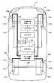
- FIG. 1 is a diagram showing an example in which a vehicle braking force generator 11 according to an embodiment of the present invention is applied to an electric vehicle V.
- a common member may be provided on each of the four wheels because of being mounted on the four-wheeled electric vehicle V, for example.
- a common code is assigned between the common members, and a suffix a is added after the code of the member provided on the left front wheel in the traveling direction, and the code of the member provided on the right front wheel.
- subscripts may be omitted.
- an electric motor 13 for driving wheels is provided in an electric vehicle V (corresponding to a “vehicle” of the present invention) on which a vehicle braking force generator 11 according to an embodiment of the present invention is mounted. It has been.
- a front wheel drive shaft 15A is connected to the electric motor 13 via a power transmission mechanism (not shown).
- Wheels (front wheels) 17a and 17b are provided at both ends of the front wheel drive shaft 15A.
- wheels (rear wheels) 17c and 17d which are driven wheels, are provided at both ends of the rear wheel driven shaft 15B.
- a drive control unit 45 (see FIG. 2A) of the DRV-ECU 29, which is a drive control ECU (Electronic Control Unit) described later, controls the motor 13 to a power running state, thereby making the motor 13 an original motor. This has a function of outputting a power running torque. As a result, the electric motor 13 acts to drive the wheels 17a and 17b.
- ECU Electronic Control Unit
- the drive control unit 45 (see FIG. 2A) of the DRV-ECU 29 controls the electric motor 13 to be in a regenerative state so that the electric motor 13 is used as a generator different from the original use and outputs a regenerative torque. It has a function to make it. As a result, the electric motor 13 acts to brake the wheels 17a and 17b.
- the electric vehicle V is equipped with a vehicle battery (not shown) that functions as a power source for the electric motor 13.
- a vehicle battery for example, a lithium ion secondary battery can be suitably used.
- the electric motor 13 is connected to an inverter 19 as shown in FIG.
- the inverter 19 is connected to the in-vehicle battery via an energization cable (not shown).
- the inverter 19 has a function of converting DC power from the in-vehicle battery into AC power and converting regenerative power (AC power) of the motor 13 into DC power.
- the electric motor 13 when the electric motor 13 is used as an electric motor that is originally used, the DC power from the in-vehicle battery is converted into AC power by the inverter 19, and this AC power is supplied to the electric motor 13. .
- the motor 13 when the motor 13 is used as a generator, regenerative power (AC power) from the motor 13 is converted into DC power by the inverter 19, and this DC power is supplied to the in-vehicle battery.
- the torque and rotation speed of the electric motor 13 can be controlled by controlling the current value and frequency of the AC power using the inverter 19.
- the electric vehicle V is provided with friction brake devices 24a to 24d for braking the plurality of wheels 17a to 17d, respectively.
- the friction brake devices 24a to 24d include a brake fluid pressure generating device 26 that generates a brake fluid pressure in accordance with an operation amount of the brake pedal 23 (see FIG. 2A) by the driver, and a brake from the brake fluid pressure generating device 26. It includes calipers 27a to 27d that brake a plurality of wheels 17a to 17d by hydraulic pressure.
- the calipers 27a to 27d correspond to “braking members” of the present invention.
- the brake fluid pressure generator 26 is configured to include a master cylinder and a slave cylinder (not shown) as disclosed in, for example, Japanese Patent Application Laid-Open No. 2008-184057.
- the slave cylinder corresponds to an electric servo brake device (Electrical / Servo / Brake / system: ESB device) 16 (see FIG. 2A).
- an electric motor (not shown) drives a piston (not shown) to generate a brake fluid pressure.
- the brake fluid pressure thus generated activates the calipers 27a to 27d to generate a braking force due to friction.
- a disc brake device is employed as the friction brake device 24, but the present invention is not limited to this example.
- a drum brake device may be employed instead of the disc brake device.
- the electric vehicle V is provided with the DRV-ECU 29 as shown in FIG. Details of the DRV-ECU 29 will be described later.
- the electric vehicle V includes a VSA (Vehicle Stability Assist; VSA is a registered trademark) -ECU 30 shown in FIG. Is equivalent to the computerization support apparatus ”) 18 (see FIG. 2B). Details of the VSA device 18 and the VSA-ECU 30 will be described later.
- VSA Vehicle Stability Assist
- the electric vehicle V is provided with an ESB-ECU 31 for controlling the ESB device 16 (see FIG. 2A) as shown in FIG. Details of the ESB-ECU 31 will be described later.
- the following CAN (Controller-Area-Network) communication medium (corresponding to the "information communication medium” of the present invention) 33 are connected to each other through information communication.
- the CAN communication medium 33 is a multiplexed serial communication network generally used for information communication between in-vehicle devices. CAN has excellent data transfer speed and error detection capability.
- the “information communication medium” of the present invention is not limited to the CAN communication medium 33.
- “FlexRay” may be adopted as the “information communication medium” according to the present invention.
- the regenerative braking control related to the electric motor 13 is the friction braking control related to the brake hydraulic pressure generator 26 in order to earn the amount of electricity obtained by regenerative braking. It is preferentially applied compared to.
- “the regenerative braking control related to the electric motor 13 is preferentially applied compared to the friction braking control related to the brake fluid pressure generating device 26” means that the regenerative braking control and the friction braking control are coordinated.
- the regenerative braking control related to the electric motor 13 is preferentially applied, and the shortage of the braking force obtained by using the regenerative braking control related to the electric motor 13 is calculated using the friction braking control related to the brake fluid pressure generating device 26. It means to make up with the braking force obtained.
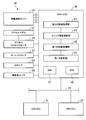
- FIG. 2A is a functional block configuration diagram showing an outline of the periphery of the vehicle braking force generator 11 according to the embodiment of the present invention.
- FIG. 2B is a functional block configuration diagram showing an outline of the periphery of the VSA-ECU 30.
- the DRV-ECU 29 has a function of performing drive control of the electric motor 13. As shown in FIG. 2A, the DRV-ECU 29 includes a vehicle speed sensor 39 for detecting the traveling speed of the electric vehicle V (hereinafter referred to as “vehicle speed”), and a select lever (not shown) used for switching the shift position. The range switch 41 for detecting the operation position is connected.
- the DRV-ECU 29 includes a first information acquisition unit 43 and a drive control unit 45 as shown in FIG. 2A.
- the first information acquisition unit 43 sends information related to the acceleration / deceleration operation amount of the accelerator pedal 21 detected by the accelerator stroke sensor 35 described later via the CAN communication medium 33. It has a function acquired from the VSA-ECU 30. Information related to the acceleration / deceleration operation amount of the accelerator pedal 21 acquired by the first information acquisition unit 43 is appropriately referred to when setting the power running torque of the electric motor 13 in the drive control unit 45.
- the first information acquisition unit 43 sends information related to the braking operation amount of the brake pedal 23 detected by a brake stroke sensor 37 described later via the CAN communication medium 33. And has a function of acquiring from the ESB-ECU 31.
- the information related to the braking operation amount of the brake pedal 23 acquired by the first information acquisition unit 43 is appropriately referred to when setting the regenerative torque of the electric motor 13 in the drive control unit 45.
- the drive control unit 45 includes information related to the vehicle speed detected by the vehicle speed sensor 39, information related to the acceleration / deceleration operation amount of the accelerator pedal 21 acquired by the first information acquisition unit 43, and the range position of the range switch 41. Based on the information and the like, the power running torque map of the electric motor 13 is set with reference to a predetermined power running torque map.
- the drive control unit 45 also includes information related to the vehicle speed detected by the vehicle speed sensor 39, information related to the braking operation amount of the brake pedal 23 acquired by the first information acquisition unit 43, and the range position of the range switch 41. And a function of setting the regenerative torque of the electric motor 13 by referring to a predetermined regenerative torque map based on the information and the like.
- the drive control unit 45 has a function of setting a target torque obtained by integrating the set power running torque and regenerative torque, and outputting a drive control signal for the electric motor 13 based on the set target torque to the inverter 19.
- the DRV-ECU 29 is constituted by a microcomputer including a CPU (Central Processing Unit), a ROM (Read Only Memory), a RAM (Random Access Memory), and the like.
- This microcomputer reads out and executes programs and data stored in the ROM, and performs execution control related to various functions including various information acquisition functions and drive control functions of the electric motor 13 that the DRV-ECU 29 has. To work. *
- the VSA-ECU 30 has a function of performing control to stabilize the behavior of the electric vehicle V. 2A and 2B, the VSA-ECU 30 includes an ABS (Antilock Brake System) device 47 and an EDC (Engine drag torque Control) device 49.
- the ABS device 47 has a function of avoiding locking of the wheels 17a to 17d through brake fluid pressure control (friction braking control) related to the brake fluid pressure generator 26.
- the EDC device 49 has a function of avoiding locking of the wheels 17a to 17d through regenerative braking control related to the electric motor 13.
- the VSA-ECU 30 includes an accelerator stroke sensor 35 for detecting the acceleration / deceleration operation amount of the accelerator pedal 21, a yaw rate sensor 52 for detecting the yaw rate generated in the electric vehicle V, and generated in the electric vehicle V.
- a G sensor 53 for detecting the longitudinal G (longitudinal acceleration) / lateral G (lateral acceleration) and a steering angle sensor 55 for detecting the steering amount and steering direction of the steering are connected.
- the VSA device 18 is a concept including all of the VSA-ECU 30 and input system sensors and output system devices connected to the VSA-ECU 30.
- the VSA-ECU 30 includes, in addition to the ABS device 47 and the EDC device 49, a second information acquisition unit 61, a slip information calculation unit 63, a first braking control unit 65, A diagnosis unit 67 is provided.
- the second information acquisition unit 61 includes information on the rotational speed (wheel speed) for each of the plurality of wheels 17a to 17d detected by the wheel speed sensors 51a to 51d, and the acceleration pedal 21 detected by the accelerator stroke sensor 35.
- Information on acceleration / deceleration operation amount, information on yaw rate occurring in electric vehicle V detected by yaw rate sensor 52, longitudinal G (longitudinal acceleration) / occurring in electric vehicle V detected by G sensor 53 It has a function of acquiring information related to the lateral G (lateral acceleration) and information related to the steering amount and steering direction of the steering detected by the steering angle sensor 55.
- the second information acquisition unit 61 has a function of acquiring information related to the vehicle speed detected by the vehicle speed sensor 39 from the DRV-ECU 29 via the CAN communication medium 33. Have.
- the slip information calculation unit 63 includes information related to the vehicle speed acquired by the second information acquisition unit 61 and information related to the rotation speed (wheel speed) for each of the plurality of wheels 17a to 17d when the electric vehicle V is traveling. Based on this, it has a function of calculating a slip ratio (corresponding to “slip information” of the present invention) SR for each of the plurality of wheels 17a to 17d. Information on the slip rate SR for each of the plurality of wheels 17a to 17d obtained by the slip information calculation unit 63 is used when the first braking control unit 65 determines whether the ABS device 47 or the EDC device 49 is required to operate. As appropriate.
- the first braking control unit 65 basically operates the ABS device 47 and the EDC device 49 based on information related to the slip rate SR for each of the plurality of wheels 17a to 17d obtained by the slip information calculation unit 63.
- 13 has a function of sending to the ESB-ECU 31 command information related to cooperative braking control related to at least one of regenerative braking control according to 13 or friction braking control according to the brake fluid pressure generator 26.
- the first braking control unit 65 estimates the behavior of the electric vehicle V based on detection signals of various sensors including the wheel speed sensors 51a to 51d, the G sensor 53, the steering angle sensor 55, and the hydraulic pressure sensor 57.
- the regenerative braking control command for the electric motor 13 is issued so that the braking force according to the calculation result relating to the braking force for each of the plurality of wheels 17a to 17d is obtained, and the plurality of wheels 1 A function of adjusting the regenerative braking torque of each a ⁇ 17d, respectively.
- the first braking control unit 65 determines that when one or more of the slip ratios SR for each of the plurality of wheels 17a to 17d exceeds a predetermined first slip ratio threshold SRth1, that is, When any one or more of the wheels 17a to 17d is in a slip tendency, the ESB-ECU 31 is used to adjust the braking force of the target wheel in the slip tendency, thereby stabilizing the behavior of the electric vehicle V. Works to let you.
- the first braking control unit 65 adjusts the braking force of the target wheel that tends to slip.
- the first braking force adjustment method the first braking control unit 65 performs predetermined friction braking using the brake fluid pressure generated by the brake fluid pressure generating device 26, so that the friction for each of the plurality of wheels 17a to 17d is achieved. Adjust the braking torque.
- the first braking control unit 65 adjusts the regenerative braking torque for each of the plurality of wheels 17a to 17d by causing the electric motor 13 to perform predetermined regenerative braking.
- the first braking control unit 65 may adjust both the friction braking torque and the regenerative braking torque by using a combination of the first and second braking force adjusting methods.
- the first braking control unit 65 acquires information related to the steering amount and steering direction of the steering, information related to the acceleration / deceleration operation amount of the accelerator pedal 21, brake information acquired by the second information acquisition unit 61, Based on information related to the amount of braking operation of the pedal 23, etc., it has a function of obtaining a target behavior of the electric vehicle V intended by the driver by calculation. Further, the first braking control unit 65 provides information on the longitudinal G (longitudinal acceleration) / lateral G (lateral acceleration) generated in the electric vehicle V and the rotational speed (wheel speed) for each of the plurality of wheels 17a to 17d. ) To obtain the actual behavior of the electric vehicle V by calculation.
- the first braking control unit 65 determines the degree of understeer or oversteer based on the target behavior and actual behavior of the electric vehicle V intended by the driver. As a result of the determination, when it is determined that any one or more of the plurality of wheels 17a to 17d is in a slip tendency, the ESB-ECU 31 is used to mediate the target wheel in a slip tendency as described above. The braking force is adjusted, and with this, the operation of the electric vehicle V is stabilized.
- the first braking control unit 65 controls the regenerative braking when the VSA device 18 is operating normally and the cooperative braking control including at least the regenerative braking control related to the electric motor 13 is actually performed.
- the ESB-ECU 31 sends a braking control command to gradually reduce the amount until it reaches zero, and to maintain the control state when the control amount related to regenerative braking becomes zero after the control amount related to regenerative braking becomes zero. Operates to send to.
- the state where “the VSA device 18 is operating normally” means a state where the ABS device 47 and the EDC device 49 are not inoperable. Specifically, for example, the case where either the ABS device 47 or the EDC device 49 is currently in operation or a request for early regeneration stop, which will be described later, is being performed, the VSA device 18 is operating normally. This is the case.
- the control amount related to regenerative braking is gradually reduced to zero means that the regenerative braking force is gradually reduced to a linear shape over time, an aspect where the regenerative braking force is gradually reduced stepwise, and an aspect related to a combination thereof. Is included.
- the fast regeneration is a second state in which any one or more of the slip rates SR for each of the plurality of wheels 17a to 17d is lower than, for example, the first slip rate threshold SRth1 related to the operation trigger of the ABS device 47.
- the slip ratio threshold SRth2 is exceeded, the regenerative braking related to the electric motor 13 is terminated at an earlier timing than in the normal time.
- the first braking control unit 65 is running the electric vehicle V on a low ⁇ road such as a wet road or a snowy road (the deviation of the wheel speed between the front wheel and the rear wheel, the inner wheel and the outer wheel In a scene where the wheel speed deviation exceeds a predetermined threshold value), a quick regeneration stop is requested.
- a scene running on a low ⁇ road performing cooperative braking control with appropriate distribution of regenerative braking and friction braking causes a time delay in braking control operation by the time required for allocation ratio calculation related to cooperative braking control. There is a risk that.
- the response to the braking control operation is accelerated by stopping the cooperative braking control and requesting the friction braking to be unified by requesting the quick regeneration stop.
- the purpose of this is to improve the performance stabilization support performance of the electric vehicle V exhibited.
- the first braking control unit 65 displays an ABS operation flag indicating whether or not the ABS device 47 is in operation and an EDC operation flag indicating whether or not the EDC device 49 is in operation. 49 has a function of rewriting according to the determination result relating to the necessity of operation. Further, the first braking control unit 65 sets a regenerative early stop flag indicating whether or not the regenerative braking related to the electric motor 13 is terminated at an earlier timing than in the normal time, and the slip ratio SR for each of the plurality of wheels 17a to 17d. And a function of rewriting according to the comparison result with the second slip ratio threshold value SRth2.
- Either one of the first braking control unit 65 and the second braking control unit (described later) 73 or both of them corresponds to the “braking control unit” of the present invention.
- the first braking control unit 65 determines that any one or more of the plurality of wheels 17a to 17d is in a slip tendency, the braking force of one or more target wheels in the slip tendency is adjusted.
- the ABS control is performed so as to reduce the brake fluid pressure, it is necessary to promptly return the target wheel that is in a slip tendency to the rotational state for the purpose of stabilizing the behavior of the electric vehicle V. .
- the first braking control unit 65 of the VSA-ECU 30 and the drive control unit 45 of the DRV-ECU 29 perform the following cooperative braking control. That is, the first braking control unit 65 of the VSA-ECU 30 sends information related to the operating state of the ABS device 47 (information about what ABS control is performed on which target wheel), and the CAN communication medium 33. To the drive control unit 45 of the DRV-ECU 29.
- the drive control unit 45 of the DRV-ECU 29 outputs a drive control signal for the electric motor 13 to the inverter 19 based on information relating to the operating state of the ABS device 47, vehicle speed, and the like. Then, the electric motor 13 related to the target wheel having a slip tendency is controlled to a power running state in which a predetermined power running torque is output. As a result, the target wheel that has a tendency to slip can be quickly returned to the rotating state, and thus the behavior of the electric vehicle V can be quickly stabilized.
- the first diagnosis unit 67 has a function of diagnosing whether or not the VSA device 18 is in an abnormal state.
- the VSA device 18 is a concept including a VSA-ECU 30 and various sensors 35, 51, 52, 53, 55 connected to the VSA-ECU 30.
- the first diagnosis unit 67 makes a diagnosis that the VSA device 18 is abnormal.
- the first diagnosis unit 67 makes a diagnosis that the VSA device 18 is abnormal.
- the case where the detection output level of the wheel speed sensors 51a to 51d is out of the normal range corresponds to a case where there is a high probability that some abnormality has occurred in the wheel speed sensors 51a to 51d.
- the detection outputs of the wheel speed sensors 51a to 51d are indispensable information for realizing the VSA control function (including the ABS control function and the EDC control function). Therefore, the first diagnosis unit 67 makes a diagnosis that the VSA device 18 is in an abnormal state when the detection output levels of the wheel speed sensors 51a to 51d are out of the normal range.
- the first diagnosis unit 67 suppresses slipping of the wheels 17a to 17d between the first braking control unit 65 of the VSA-ECU 30 and the drive control unit 45 of the DRV-ECU 29 via the CAN communication medium 33.
- a function of diagnosing whether or not information communication related to cooperative braking control is abnormal.
- the first diagnosis unit 67 checks whether or not information indicating that it is an abnormality diagnosis target is added to the communication message.
- the first diagnosis unit 67 diagnoses that the information communication related to the cooperative braking control is abnormal.
- whether the information communication related to the cooperative braking control is abnormal or not is determined because the information related to the cooperative braking control is determined by the first braking control unit 65 and the driving control unit 45 in the drive control unit 45.
- the information is indispensable for accurately performing the coordinated braking control (for example, drive control of the electric motor 13 performed based on information related to the operating state of the ABS).
- the diagnostic information regarding whether or not the information communication related to the cooperative braking control is abnormal includes diagnostic information regarding whether or not the CAN communication medium 33 used for information communication between the VSA-ECU 30 and the DRV-ECU 29 is abnormal. Yes.
- the diagnosis target by the first diagnosis unit 67 is not limited to the detection output of the wheel speed sensors 51a to 51d and the information communication message related to the cooperative braking control.
- the detection outputs of other sensors referred to in the ABS device 47 and the EDC device 49 may be appropriately used as a diagnosis target by the first diagnosis unit 67.
- One of the first diagnosis unit 67 and the second diagnosis unit (described later) 75, or both of them corresponds to the “diagnosis unit” of the present invention.
- the VSA-ECU 30 determines whether or not the VSA device 18 is abnormal at a predetermined cycle, or at a rewrite timing of information on the ABS operation flag, EDC operation flag, or regeneration fast stop flag. Is sent to the ESB-ECU 31 via the CAN communication medium 33 together with information related to the ABS operation flag, EDC operation flag, and regeneration fast stop flag. However, in the case where an abnormality has occurred in the CAN communication medium 33, the VSA-ECU 30 cannot send diagnostic information regarding whether or not the VSA device 18 is abnormal to the ESB-ECU 31. In such a case, as will be described later, in the second diagnosis unit 75 included in the ESB-ECU 31, diagnosis relating to whether or not the VSA device 18 is abnormal may be performed in an integrated manner.
- the VSA-ECU 30 is composed of a microcomputer having a CPU (Central Processing Unit), a ROM (Read Only Memory), a RAM (Random Access Memory), and the like. This microcomputer reads and executes programs and data stored in the ROM, and the VSA-ECU 30 has various information acquisition functions, slip information calculation functions, information communication abnormality diagnosis functions related to the VSA device 18, and It operates to perform execution control related to various functions including a braking control function for stabilizing the behavior of the electric vehicle V.
- a microcomputer having a CPU (Central Processing Unit), a ROM (Read Only Memory), a RAM (Random Access Memory), and the like.
- This microcomputer reads and executes programs and data stored in the ROM, and the VSA-ECU 30 has various information acquisition functions, slip information calculation functions, information communication abnormality diagnosis functions related to the VSA device 18, and It operates to perform execution control related to various functions including a braking control function for stabilizing the behavior of the electric vehicle V.
- the ESB-ECU 31 detects the brake fluid pressure of each part of the brake stroke sensor 37 for detecting the brake operation amount of the brake pedal 23 and the hydraulic system in the brake hydraulic pressure generator 26, respectively.
- a hydraulic pressure sensor 57 is connected.
- the ESB-ECU 31 includes a third information acquisition unit 71, a second braking control unit 73, and a second diagnosis unit 75.
- the third information acquisition unit 71 includes information related to the braking operation amount of the brake pedal 23 detected by the brake stroke sensor 37, and the brake fluid of each part detected by the hydraulic pressure sensor 57. It has a function to acquire information related to pressure.
- the third information acquisition unit 71 includes diagnostic information related to whether or not the VSA device 18 is abnormal, information related to the cooperative braking control, information related to an ABS operation flag, an EDC operation flag, and a regeneration early stop flag, In addition, it has a function of acquiring braking control command information related to at least one of regenerative braking control related to the electric motor 13 or friction braking control related to the brake hydraulic pressure generating device 26 from the VSA-ECU 30 via the CAN communication medium 33.
- the second braking control unit 73 basically performs braking based on information on the brake operation amount of the brake pedal 23 acquired by the third information acquisition unit 71 and information on the brake hydraulic pressure of each unit. It has a function of controlling the friction braking torque so that the friction braking torque related to the hydraulic pressure generator 26 follows the target braking torque corresponding to the amount of braking operation of the brake pedal 23.
- the second braking control unit 73 obtains diagnostic information about whether or not the VSA device 18 is abnormal, information about the cooperative braking control, ABS operation flag, EDC operation, which is acquired by the third information acquisition unit 71. Based on brake control command information related to at least one of the information related to the flag and the regenerative quick stop flag, and the regenerative braking control related to the electric motor 13 or the friction braking control related to the brake fluid pressure generating device 26, the brake fluid In consideration of the friction braking torque related to the pressure generating device 26, the regenerative braking control related to the electric motor 13 and the friction braking control related to the brake hydraulic pressure generating device 26 are integrated.
- the second diagnosis unit 75 basically has a function of performing an abnormality diagnosis of the CAN communication medium 33 used for information communication between the VSA-ECU 30 and the ESB-ECU 31.
- the second diagnosis unit 75 is used for diagnosis information regarding whether or not the VSA device 18 acquired by the third information acquisition unit 71 is abnormal and information communication between the VSA-ECU 30 and the ESB-ECU 31. Based on the diagnostic information of the CAN communication medium 33, it has a function of diagnosing the abnormality of the VSA device 18 in an integrated manner.
- the ESB-ECU 31 includes a microcomputer having a CPU (Central Processing Unit), a ROM (Read Only Memory), a RAM (Random Access Memory), and the like.
- This microcomputer reads out and executes programs and data stored in the ROM, and provides them to various information acquisition functions, abnormality diagnosis functions of the CAN communication medium 33, and the calipers 27a to 27d that the ESB-ECU 31 has. It operates to perform execution control related to various functions including a brake fluid pressure (braking torque) control function.
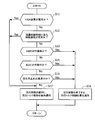
- FIG. 3 is a flowchart showing the flow of the braking control process executed by the vehicle braking force generator 11 according to the embodiment of the present invention.
- the second braking control unit 73 of the ESB-ECU 31 actually performs cooperative braking control including both regenerative braking control related to the electric motor 13 and friction braking control related to the brake hydraulic pressure generator 26. Shall.
- step S11 shown in FIG. 3 the second diagnosis unit 75 of the ESB-ECU 31 determines whether the VSA device 18 is based on the diagnosis information sent from the VSA-ECU 30 regarding whether the VSA device 18 is abnormal. Diagnose whether it is abnormal. If a diagnosis that the VSA device 18 is abnormal is made as a result of the diagnosis in step S11 (“Yes” in step S11), the ESB-ECU 31 jumps the process flow to step S17. On the other hand, as a result of the diagnosis in step S11, if the diagnosis that the VSA device 18 is not abnormal is made (“No” in step S11), the ESB-ECU 31 advances the process flow to the next step S12.
- step S12 the second diagnosis unit 75 of the ESB-ECU 31 is performed between the first braking control unit 65 of the VSA-ECU 30 and the drive control unit 45 of the DRV-ECU 29 sent from the VSA-ECU 30. It is diagnosed whether information communication related to cooperative braking control (in particular, information communication related to the VSA device 18) is abnormal.
- step S12 when the diagnosis that the information communication related to the cooperative braking control is abnormal is made (“Yes” in step S12), the ESB-ECU 31 jumps the process flow to step S17.
- the diagnosis that information communication using the CAN communication medium 33 is not abnormal is made as a result of the diagnosis in step S12 (“No” in step S12)
- the ESB-ECU 31 moves the processing flow to the next step. Proceed to S13.
- step S13 the ESB-ECU 31 refers to the ABS operation flag sent from the VSA-ECU 30, and determines whether or not the ABS device 47 is operating. As a result of the determination in step S13, when it is determined that the ABS device 47 is in operation (“Yes” in step S13), the ESB-ECU 31 jumps the process flow to step S16. On the other hand, if it is determined in step S13 that the ABS device is not in operation (“No” in step S13), the ESB-ECU 31 advances the processing flow to the next step S14. .
- step S14 the ESB-ECU 31 refers to the EDC operation flag sent from the VSA-ECU 30, and determines whether or not the EDC device 49 is operating. If it is determined in step S14 that the EDC device 49 is in operation (“Yes” in step S14), the ESB-ECU 31 jumps the process flow to step S16. On the other hand, if it is determined in step S14 that the EDC device 49 is not in operation (“No” in step S14), the ESB-ECU 31 advances the process flow to the next step S15. Make it. It is determined whether or not the EDC device 49 is operating.
- step S15 the ESB-ECU 31 refers to the EDC operation flag sent from the VSA-ECU 30, and determines whether or not a request for fast regeneration is being requested. As a result of the determination in step S15, if it is determined that the request for quick regeneration stop is being made (“Yes” in step S15), the ESB-ECU 31 jumps the process flow to step S16. On the other hand, as a result of the determination in step S15, if it is determined that the request for quick regeneration stop is not being made (“No” in step S15), the ESB-ECU 31 advances the process flow to the next step S17. Make it.
- step S16 the second braking control unit 73 of the ESB-ECU 31 gradually reduces the control amount related to the regenerative braking of the electric motor 13 until it becomes zero, and after the control amount related to the regenerative braking becomes zero, Brake control is performed to maintain the control state when the control amount related to braking becomes zero. That is, the second braking control unit 73 terminates regenerative braking and performs braking control (cooperative braking control different from the principle) in which powering torque control is preferentially applied.
- the second braking control unit 73 of the ESB-ECU 31 performs information communication related to cooperative braking control performed between the first braking control unit 65 of the VSA-ECU 30 and the drive control unit 45 of the DRV-ECU 29. It is normal, the VSA device 18 is operating normally, the ABS device 47 is operating, the EDC device 49 is operating, or the regenerative stop is being requested. In this case, the power running torque of the electric motor 13 is set based on the information related to the operating state of the VSA device 18.
- the information related to the operating state of the VSA device 18 means information regarding what braking control (for example, ABS control) is performed on the target wheel with what braking torque.
- the second braking control unit 73 sets a target torque obtained by integrating the regenerative torque (in principle, zero except for the process of decreasing the control amount related to regenerative braking) and the power running torque, and based on the set target torque Then, braking control is performed with priority applied to the power running torque control of the electric motor 13. After the series of processes, the ESB-ECU 31 returns the process flow to step S11 and repeats the following processes.
- the information communication related to the cooperative braking control is normal, the VSA device 18 is operating normally, the ABS device 47 is operating, the EDC device 49 is operating, or the regeneration is stopped quickly.
- the power running torque is output from the electric motor 13 based on the information related to the operating state of the VSA device 18. Accordingly, when any one of the ABS device 47, the EDC device 49, and the quick regeneration stop is operated to reduce the brake fluid pressure, the target wheel can be accurately returned to the rotating state. As a result, the behavior of the electric vehicle V can be quickly stabilized.
- step S17 the second braking control unit 73 of the ESB-ECU 31 maintains the regenerative braking related to the electric motor 13, and performs the braking control (basic cooperative braking control) with priority applied to the regenerative torque control. That is, the second braking control unit 73 performs regenerative braking related to the electric motor 13 based on the target torque used until the VSA device 18 enters an abnormal state or immediately before the information communication related to the cooperative braking control enters an abnormal state. By maintaining the state as it is, cooperative braking control with priority applied to regenerative torque control is performed.
- the information communication related to the cooperative braking control is normal, the VSA device 18 is operating normally, the ABS device 47 is operating, and the EDC device 49 is operating. Or, based on information related to the braking state of the electric vehicle V (for example, the deceleration detected by the G sensor 53) in a state where any one or more of the conditions during which quick regeneration is being requested is satisfied.
- the regenerative torque of the electric motor 13 is set.
- the second braking control unit 73 sets a target torque obtained by integrating the regenerative torque and the power running torque (in this case, zero because the regenerative torque is set), and based on the set target torque, the electric motor 13 regenerative torque control is performed.
- the ESB-ECU 31 returns the process flow to step S11 and repeats the following processes.
- the scene where the process of step S17 is performed is nothing but the scene where the regenerative torque control (regenerative braking) by the electric motor 13 is performed.
- the regenerative braking control related to the electric motor 13 is compared with the friction braking control related to the brake hydraulic pressure generation device 26 in order to earn an electric quantity obtained by regenerative braking. This is because priority is applied.
- the cooperative braking control (basic cooperative braking control) that preferentially applies the regenerative torque control is continued by maintaining the regenerative braking control related to the electric motor 13 as it is.
- the information communication related to the cooperative braking control or the control for prohibiting the regenerative braking related to the electric motor 13 is performed when at least one of the VSA device 18 is abnormal.
- a ring can be given to the driver.
- the kinetic energy of the electric vehicle V can be converted into electric energy and recovered, the amount of electricity obtained by regenerative braking can be earned.
- a vehicular braking force generator 11 based on a first aspect includes an electric motor 13 that applies driving force and regenerative braking force to wheels 17a to 17d of an electric vehicle (vehicle) V, and an electric vehicle (vehicle).
- Brake fluid pressure generating device 26 for generating brake fluid pressure to be applied to V calipers (braking members) 27a to 27d, slip information calculating unit 63 for obtaining slip information (slip rate) of the wheels 17a to 17d, and the slip information
- at least a VSA device (behavior stabilization support device) 18 that performs friction braking control related to the brake fluid pressure generator 26 and a diagnosis that diagnoses the VSA device 18 so as to suppress slipping of the wheels 17a to 17d.
- Brake control including at least one of a regenerative braking control related to the motor and the motor 13 or a friction braking control related to the brake fluid pressure generating device 26 And a brake control unit that performs.
- the “diagnosis unit” means at least one of the first or second diagnosis units 67 and 75 (hereinafter the same).
- the “braking control unit” means at least one of the first or second braking control units 65 and 73 (hereinafter the same).
- the braking control unit acquires diagnostic information indicating that the VSA device 18 is abnormal during the cooperative braking control including at least the regenerative braking control related to the electric motor 13. In this case, the state of the regenerative braking control related to the electric motor 13 is maintained.
- the vehicle braking force generation device 11 compared to the case where control is performed to prohibit regenerative braking related to the motor 13 when the ABS device 47 of the VSA device 18 is in an abnormal state, for example.
- a good braking feeling can be given to the driver.
- the kinetic energy of the electric vehicle V can be converted into electric energy and recovered, the amount of electricity obtained by regenerative braking can be earned.
- the second braking control unit 73 receives a control signal indicating that the regenerative braking related to the electric motor 13 is prohibited. .
- the control signal received when the VSA device 18 is in an abnormal state is highly likely to contain an error.
- the second braking control unit 73 performs the control to prohibit the regenerative braking related to the electric motor 13 based on the control signal for prohibiting the regenerative braking related to the electric motor 13 having a high probability of including an error in this manner, If this is the case, the fuel consumption (electricity cost) that would have been obtained may be impaired.
- the vehicle braking force generator 11 based on the first aspect, when the VSA device 18 is in an abnormal state, the state of the regenerative braking control related to the electric motor 13 is maintained. It is possible to expect an effect of avoiding a situation where the fuel consumption (electricity cost) that would have been lost is lost.
- the vehicular braking force generator 11 based on the first aspect when the VSA device 18 falls into an abnormal state, the regeneration associated with the motor 13 is performed. In order to maintain the state of the braking control, it is possible to expect an effect of avoiding a situation where the behavior of the electric vehicle (vehicle) V becomes unstable by making the driving wheels firmly contact the road surface.
- the vehicle braking force generator 11 based on the second aspect includes a drive control unit 45 that performs drive control of the electric motor 13 based on acceleration / deceleration operation information of the electric vehicle (vehicle) V; And a CAN communication medium (information communication medium) 33 used when performing information communication between the brake control unit and the drive control unit 45.
- the diagnosis unit further has a function of performing an abnormality diagnosis of the information communication performed via the CAN communication medium (information communication medium) 33, and the brake control unit Is information related to the cooperative braking control performed between the braking control unit and the drive control unit 45 in order to suppress slip of the wheels 17a to 17d during the cooperative braking control including at least the regenerative braking control related to the electric motor 13.
- a configuration in which the state of regenerative braking control related to the electric motor 13 is maintained when diagnostic information indicating that communication is abnormal may be employed.
- the vehicle braking force generation device 11 based on the second aspect for example, in the case where some abnormality (including abnormality of the CAN communication medium 33) occurs in the information communication related to the cooperative braking control,
- some abnormality including abnormality of the CAN communication medium 33
- the case of maintaining the state of the regenerative braking control related to the electric motor 13 is specifically described. Can be managed.
- the diagnosis unit performs abnormality diagnosis of the information communication performed via the CAN communication medium (information communication medium) 33.
- the brake control unit further includes a function between the brake control unit and the drive control unit 45 in order to suppress slipping of the wheels 17a to 17d during the cooperative brake control including at least the regenerative braking control related to the electric motor 13. If the information communication related to the coordinated braking control to be performed is abnormal and the diagnostic information indicating that the VSA device (behavior stabilization support device) 18 is abnormal is acquired, the state of the regenerative braking control related to the electric motor 13 is changed. A configuration to maintain may be employed.
- the vehicle braking force generation device 11 based on the third aspect for example, in the case where some abnormality has occurred in the CAN communication medium 33 and the VSA device 18 is in an abnormal state,
- the case of maintaining the state of the regenerative braking control related to the electric motor 13 is specifically described. Can be managed.
- the diagnosis unit performs abnormality diagnosis of the information communication performed via the CAN communication medium (information communication medium) 33.
- the brake control unit further includes a function between the brake control unit and the drive control unit 45 in order to suppress slipping of the wheels 17a to 17d during the cooperative brake control including at least the regenerative braking control related to the electric motor 13.
- the regenerative braking related to the motor 13 is performed.
- a configuration in which the control amount is gradually decreased may be employed.
- the vehicle braking force generation device 11 for example, information communication of the CAN communication medium 33 is normal and the VSA device 18 is operating normally (for example, the ABS device 47 is In order to gradually reduce the control amount of the regenerative braking related to the electric motor 13 in the case where the EDC device 49 is in operation, or in the case where any one or more of the conditions in which regenerative quick stop is being requested is satisfied)
- the behavior stabilization performance exhibited by the VSA device 18 can be improved.
- the vehicle braking force generator 11 based on the fifth aspect is the vehicle braking force generator 11 based on the fourth aspect, and the braking control unit relates to the electric motor 13.
- a configuration may be adopted in which the control amount is made zero by gradually reducing the control amount of regenerative braking, and then the state where the control amount is zero is maintained.
- the control amount of the regenerative braking related to the electric motor 13 is gradually decreased to make the control amount zero, and then the state where the control amount is zero is maintained. Therefore, the behavior stabilization performance exhibited by the VSA device 18 can be further improved as compared with the above-described operational effects produced by the vehicle braking force generator 11 based on the fourth aspect.
- the slip ratio is exemplified as one aspect of the slip information indicating the slip tendency of the wheels 17a to 17d, but the present invention is not limited to this example.
- the slip tendency of the wheels 17a to 17d may be grasped based on the rotational speed difference between the plurality of wheels 17a to 17d, and the slip tendency thus grasped may be used as the slip information.
- the vehicle braking force generator 11 according to the embodiment of the present invention is applied to the electric vehicle V including only the electric motor 13 as a power source.
- the present invention is not limited to this example. You may apply this invention with respect to the hybrid vehicle provided with the electric motor 13 and the reciprocating engine as a motive power source.
- the ABS device 47 has been described as the functional member having the function of suppressing the slip of the wheels 17a to 17d, but the present invention is not limited to this example.
- the functional unit having the function of suppressing the slip of the wheels 17a to 17d for example, a functional member that suppresses the slip of the wheels 17a to 17d by controlling the brake torque by the reciprocating engine brake may be applied to the present invention. Good.
Abstract
Priority Applications (8)
| Application Number | Priority Date | Filing Date | Title |
|---|---|---|---|
| CA2879295A CA2879295C (fr) | 2012-07-19 | 2013-07-16 | Dispositif de generation de force de freinage pour vehicule |
| JP2014525825A JP5924628B2 (ja) | 2012-07-19 | 2013-07-16 | 車両用制動力発生装置 |
| US14/415,188 US9180848B2 (en) | 2012-07-19 | 2013-07-16 | Vehicle brake force generation device |
| EP13819606.8A EP2876007B1 (fr) | 2012-07-19 | 2013-07-16 | Dispositif de génération de force de freinage pour véhicule |
| AU2013291209A AU2013291209B2 (en) | 2012-07-19 | 2013-07-16 | Vehicle brake force generation device |
| CN201380036881.6A CN104428179B (zh) | 2012-07-19 | 2013-07-16 | 车辆用制动力产生装置 |
| BR112015001097-0A BR112015001097B1 (pt) | 2012-07-19 | 2013-07-16 | Dispositivo de geração de força de frenagem de veículo |
| MX2015000845A MX349850B (es) | 2012-07-19 | 2013-07-16 | Dispositivo de generacion de fuerza de frenado de vehículo. |
Applications Claiming Priority (2)
| Application Number | Priority Date | Filing Date | Title |
|---|---|---|---|
| JP2012-161010 | 2012-07-19 | ||
| JP2012161010 | 2012-07-19 |
Publications (1)
| Publication Number | Publication Date |
|---|---|
| WO2014013991A1 true WO2014013991A1 (fr) | 2014-01-23 |
Family
ID=49948817
Family Applications (1)
| Application Number | Title | Priority Date | Filing Date |
|---|---|---|---|
| PCT/JP2013/069313 WO2014013991A1 (fr) | 2012-07-19 | 2013-07-16 | Dispositif de génération de force de freinage pour véhicule |
Country Status (8)
| Country | Link |
|---|---|
| US (1) | US9180848B2 (fr) |
| EP (1) | EP2876007B1 (fr) |
| JP (1) | JP5924628B2 (fr) |
| CN (1) | CN104428179B (fr) |
| AU (1) | AU2013291209B2 (fr) |
| CA (1) | CA2879295C (fr) |
| MX (1) | MX349850B (fr) |
| WO (1) | WO2014013991A1 (fr) |
Cited By (1)
| Publication number | Priority date | Publication date | Assignee | Title |
|---|---|---|---|---|
| CN109982902A (zh) * | 2016-10-19 | 2019-07-05 | 罗伯特·博世有限公司 | 用于再生和摩擦制动混合的横向动态控制 |
Families Citing this family (17)
| Publication number | Priority date | Publication date | Assignee | Title |
|---|---|---|---|---|
| JP6255775B2 (ja) * | 2013-07-30 | 2018-01-10 | 三菱自動車工業株式会社 | ブレーキ制御装置 |
| JP2015143039A (ja) * | 2014-01-31 | 2015-08-06 | トヨタ自動車株式会社 | 車両 |
| JP6247186B2 (ja) * | 2014-09-30 | 2017-12-13 | オートリブ日信ブレーキシステムジャパン株式会社 | 車両用制御装置 |
| JP6272203B2 (ja) * | 2014-09-30 | 2018-01-31 | オートリブ日信ブレーキシステムジャパン株式会社 | 車両用制御装置 |
| KR101551124B1 (ko) * | 2014-10-10 | 2015-09-07 | 현대자동차주식회사 | Abs 협조 제어 성능을 강화한 전자제어 4wd시스템 및 제어방법 |
| US9676280B2 (en) * | 2015-06-09 | 2017-06-13 | Caterpillar Inc. | Braking management in a dual braking system |
| CN106608201B (zh) * | 2015-10-26 | 2019-04-19 | 比亚迪股份有限公司 | 电动车辆及其主动安全控制系统和方法 |
| JP6374372B2 (ja) * | 2015-11-27 | 2018-08-15 | 株式会社アドヴィックス | 異常診断装置 |
| DE102016214195A1 (de) * | 2016-08-02 | 2018-02-08 | Robert Bosch Gmbh | Verfahren zur Funktionsprüfung einer elektromechanischen Bremsvorrichtung |
| JP6506236B2 (ja) * | 2016-11-28 | 2019-04-24 | トヨタ自動車株式会社 | 電動ブレーキ制御装置 |
| KR101824410B1 (ko) | 2017-06-29 | 2018-02-01 | 쌍용자동차 주식회사 | 전기 자동차의 회생제동 기능을 이용한 차속 조절방법 |
| DE102018111679A1 (de) * | 2018-05-15 | 2019-11-21 | Wabco Gmbh | System mit einem Steuergerät für ein Nutzfahrzeug sowie ein Verfahren zum Betreiben eines Nutzfahrzeugs mit dem System |
| DE102018210566A1 (de) * | 2018-06-28 | 2020-01-02 | Robert Bosch Gmbh | Hydraulisches Bremssystem für ein Fahrzeug mit mindestens zwei Achsen |
| KR102575441B1 (ko) * | 2018-10-24 | 2023-09-06 | 현대자동차주식회사 | 차량의 회생제동 제어 방법 |
| CN112606702B (zh) * | 2020-11-30 | 2022-06-03 | 江铃汽车股份有限公司 | 一种能量回收控制方法、系统、存储介质及计算机设备 |
| CN112896121B (zh) * | 2021-01-28 | 2022-02-08 | 中汽创智科技有限公司 | 一种制动系统及制动方法 |
| US20230150371A1 (en) * | 2021-11-18 | 2023-05-18 | GM Global Technology Operations LLC | Automated friction brake assisted vehicle stop |
Citations (5)
| Publication number | Priority date | Publication date | Assignee | Title |
|---|---|---|---|---|
| JPH10203334A (ja) * | 1997-01-17 | 1998-08-04 | Honda Motor Co Ltd | 車両用制動力制御装置における制御方法 |
| JP2008184057A (ja) | 2007-01-30 | 2008-08-14 | Honda Motor Co Ltd | ブレーキ装置 |
| JP2010247782A (ja) | 2009-04-20 | 2010-11-04 | Fuji Heavy Ind Ltd | 電気自動車の制御装置 |
| JP2011183822A (ja) * | 2010-03-04 | 2011-09-22 | Toyota Motor Corp | ブレーキ制御装置 |
| JP2012126352A (ja) * | 2010-12-17 | 2012-07-05 | Honda Motor Co Ltd | 車両用ブレーキ装置 |
Family Cites Families (11)
| Publication number | Priority date | Publication date | Assignee | Title |
|---|---|---|---|---|
| US5423600A (en) * | 1994-02-14 | 1995-06-13 | General Motors Corporation | Brake system with brake gain shifting |
| JP3528452B2 (ja) * | 1996-08-14 | 2004-05-17 | トヨタ自動車株式会社 | 制動力制御装置 |
| DE19738690C2 (de) * | 1997-09-04 | 2002-05-29 | Bosch Gmbh Robert | Verfahren und Vorrichtung zur Steuerung der Bremsanlage eines Fahrzeugs |
| US6957870B2 (en) * | 1999-12-24 | 2005-10-25 | Toyota Jidosha Kabushiki Kaisha | Braking pressure control apparatus capable of switching between two brake operating states using power-operated and manually operated pressure sources, respectively |
| US6827167B2 (en) * | 2002-03-28 | 2004-12-07 | Ford Global Technologies, Llc | Hybrid electric vehicle torque distribution |
| US6629026B1 (en) * | 2002-04-12 | 2003-09-30 | Ford Motor Company | Hybrid electric vehicle with motor torque fill in |
| US7147078B2 (en) * | 2004-07-01 | 2006-12-12 | Ford Global Technologies, Llc | Charging a fluid accumulator while operating a hybrid vehicle powertrain including an engine and a pump/motor |
| US7689331B2 (en) * | 2004-12-01 | 2010-03-30 | Ise Corporation | Method of controlling engine stop-start operation for heavy-duty hybrid-electric and hybrid-hydraulic vehicles |
| DE102005055751B4 (de) * | 2005-04-21 | 2018-09-06 | Ipgate Ag | Druckmodulatorsteuerung |
| JP4250149B2 (ja) * | 2005-05-10 | 2009-04-08 | 株式会社デンソー | エンジン始動制御システム |
| US20070222287A1 (en) * | 2006-03-22 | 2007-09-27 | Ford Global Technologies, Llc | Automotive regenerative and friction braking system and control method |
-
2013
- 2013-07-16 MX MX2015000845A patent/MX349850B/es active IP Right Grant
- 2013-07-16 US US14/415,188 patent/US9180848B2/en active Active
- 2013-07-16 JP JP2014525825A patent/JP5924628B2/ja not_active Expired - Fee Related
- 2013-07-16 CA CA2879295A patent/CA2879295C/fr active Active
- 2013-07-16 WO PCT/JP2013/069313 patent/WO2014013991A1/fr active Application Filing
- 2013-07-16 AU AU2013291209A patent/AU2013291209B2/en active Active
- 2013-07-16 EP EP13819606.8A patent/EP2876007B1/fr active Active
- 2013-07-16 CN CN201380036881.6A patent/CN104428179B/zh active Active
Patent Citations (5)
| Publication number | Priority date | Publication date | Assignee | Title |
|---|---|---|---|---|
| JPH10203334A (ja) * | 1997-01-17 | 1998-08-04 | Honda Motor Co Ltd | 車両用制動力制御装置における制御方法 |
| JP2008184057A (ja) | 2007-01-30 | 2008-08-14 | Honda Motor Co Ltd | ブレーキ装置 |
| JP2010247782A (ja) | 2009-04-20 | 2010-11-04 | Fuji Heavy Ind Ltd | 電気自動車の制御装置 |
| JP2011183822A (ja) * | 2010-03-04 | 2011-09-22 | Toyota Motor Corp | ブレーキ制御装置 |
| JP2012126352A (ja) * | 2010-12-17 | 2012-07-05 | Honda Motor Co Ltd | 車両用ブレーキ装置 |
Non-Patent Citations (1)
| Title |
|---|
| See also references of EP2876007A4 |
Cited By (2)
| Publication number | Priority date | Publication date | Assignee | Title |
|---|---|---|---|---|
| CN109982902A (zh) * | 2016-10-19 | 2019-07-05 | 罗伯特·博世有限公司 | 用于再生和摩擦制动混合的横向动态控制 |
| CN109982902B (zh) * | 2016-10-19 | 2021-08-31 | 罗伯特·博世有限公司 | 用于再生和摩擦制动混合的横向动态控制 |
Also Published As
| Publication number | Publication date |
|---|---|
| EP2876007B1 (fr) | 2017-12-20 |
| US20150191159A1 (en) | 2015-07-09 |
| EP2876007A1 (fr) | 2015-05-27 |
| CA2879295A1 (fr) | 2014-01-23 |
| AU2013291209A1 (en) | 2015-02-26 |
| AU2013291209B2 (en) | 2016-08-11 |
| CN104428179A (zh) | 2015-03-18 |
| MX349850B (es) | 2017-08-15 |
| MX2015000845A (es) | 2015-07-06 |
| CA2879295C (fr) | 2017-03-14 |
| JP5924628B2 (ja) | 2016-05-25 |
| BR112015001097A2 (pt) | 2017-06-27 |
| CN104428179B (zh) | 2017-02-15 |
| US9180848B2 (en) | 2015-11-10 |
| EP2876007A4 (fr) | 2016-03-09 |
| JPWO2014013991A1 (ja) | 2016-06-30 |
Similar Documents
| Publication | Publication Date | Title |
|---|---|---|
| JP5924628B2 (ja) | 車両用制動力発生装置 | |
| EP3050765B1 (fr) | Dispositif de commande pour véhicule électrique | |
| US8886375B2 (en) | Control apparatus for electric vehicle | |
| JP6153857B2 (ja) | 車両用制動装置 | |
| US10801620B2 (en) | Vehicle brake control apparatus | |
| CN108349470A (zh) | 操作具有电动液压行车制动器和机械驻车制动器的机动车辆制动系统的方法 | |
| CN104125901A (zh) | 车辆的驻车锁定装置 | |
| JP6407732B2 (ja) | 車両制御装置 | |
| JP5359664B2 (ja) | 4輪独立駆動車両の制御装置 | |
| JP2013071549A (ja) | 車体挙動安定化装置 | |
| CN110816281A (zh) | 用于车辆回收式制动控制的控制单元、装置和方法 | |
| JP5506632B2 (ja) | 車両用ブレーキ装置 | |
| JP5766240B2 (ja) | 車両用制動装置 | |
| JP6464131B2 (ja) | 電動車両用制動装置 | |
| US20210270333A1 (en) | Vehicle control system | |
| JP6488215B2 (ja) | 車両用制動装置 | |
| JP2016043718A (ja) | 車両用制動装置 | |
| WO2022113503A1 (fr) | Dispositif de commande de véhicule et procédé de commande de véhicule | |
| WO2022264738A1 (fr) | Dispositif de commande de véhicule | |
| JP2020111245A (ja) | 車両の制動力制御装置 | |
| JP2021054371A (ja) | 制動制御装置 | |
| CN103287410A (zh) | 用于混合动力车辆或电动车辆的制动系统和制动控制方法 | |
| JP2021030835A (ja) | 制動力制御装置 | |
| JP2006280099A (ja) | 自動車およびその制御方法 | |
| BR112015001097B1 (pt) | Dispositivo de geração de força de frenagem de veículo |
Legal Events
| Date | Code | Title | Description |
|---|---|---|---|
| 121 | Ep: the epo has been informed by wipo that ep was designated in this application |
Ref document number: 13819606 Country of ref document: EP Kind code of ref document: A1 |
|
| ENP | Entry into the national phase |
Ref document number: 2014525825 Country of ref document: JP Kind code of ref document: A |
|
| ENP | Entry into the national phase |
Ref document number: 2879295 Country of ref document: CA |
|
| WWE | Wipo information: entry into national phase |
Ref document number: 14415188 Country of ref document: US |
|
| NENP | Non-entry into the national phase |
Ref country code: DE |
|
| WWE | Wipo information: entry into national phase |
Ref document number: MX/A/2015/000845 Country of ref document: MX |
|
| WWE | Wipo information: entry into national phase |
Ref document number: IDP00201500499 Country of ref document: ID |
|
| WWE | Wipo information: entry into national phase |
Ref document number: 2013819606 Country of ref document: EP |
|
| ENP | Entry into the national phase |
Ref document number: 2013291209 Country of ref document: AU Date of ref document: 20130716 Kind code of ref document: A |
|
| REG | Reference to national code |
Ref country code: BR Ref legal event code: B01A Ref document number: 112015001097 Country of ref document: BR |
|
| ENP | Entry into the national phase |
Ref document number: 112015001097 Country of ref document: BR Kind code of ref document: A2 Effective date: 20150116 |