WO2014010672A1 - 撮像装置及びプログラム - Google Patents
撮像装置及びプログラム Download PDFInfo
- Publication number
- WO2014010672A1 WO2014010672A1 PCT/JP2013/068976 JP2013068976W WO2014010672A1 WO 2014010672 A1 WO2014010672 A1 WO 2014010672A1 JP 2013068976 W JP2013068976 W JP 2013068976W WO 2014010672 A1 WO2014010672 A1 WO 2014010672A1
- Authority
- WO
- WIPO (PCT)
- Prior art keywords
- focus adjustment
- information
- subject
- focus
- acquisition unit
- Prior art date
Links
- 238000003384 imaging method Methods 0.000 title claims abstract description 1005
- 230000003287 optical effect Effects 0.000 claims abstract description 165
- 230000033001 locomotion Effects 0.000 claims description 546
- 238000000034 method Methods 0.000 claims description 291
- 230000008859 change Effects 0.000 claims description 269
- 230000008569 process Effects 0.000 claims description 244
- 230000001133 acceleration Effects 0.000 claims description 70
- 210000005252 bulbus oculi Anatomy 0.000 claims description 35
- 230000006399 behavior Effects 0.000 description 339
- 238000012545 processing Methods 0.000 description 224
- 238000012986 modification Methods 0.000 description 200
- 230000004048 modification Effects 0.000 description 200
- 238000012937 correction Methods 0.000 description 108
- 230000001629 suppression Effects 0.000 description 105
- 238000010586 diagram Methods 0.000 description 99
- 238000004091 panning Methods 0.000 description 59
- 230000002123 temporal effect Effects 0.000 description 52
- 230000014509 gene expression Effects 0.000 description 47
- 230000007423 decrease Effects 0.000 description 26
- 238000012887 quadratic function Methods 0.000 description 26
- 230000035945 sensitivity Effects 0.000 description 23
- 238000011156 evaluation Methods 0.000 description 22
- 239000000284 extract Substances 0.000 description 19
- 230000006870 function Effects 0.000 description 14
- FFBHFFJDDLITSX-UHFFFAOYSA-N benzyl N-[2-hydroxy-4-(3-oxomorpholin-4-yl)phenyl]carbamate Chemical compound OC1=C(NC(=O)OCC2=CC=CC=C2)C=CC(=C1)N1CCOCC1=O FFBHFFJDDLITSX-UHFFFAOYSA-N 0.000 description 12
- 230000002093 peripheral effect Effects 0.000 description 12
- 238000001514 detection method Methods 0.000 description 10
- 210000001508 eye Anatomy 0.000 description 10
- 238000012795 verification Methods 0.000 description 10
- 230000001965 increasing effect Effects 0.000 description 8
- 210000000887 face Anatomy 0.000 description 6
- 230000002349 favourable effect Effects 0.000 description 6
- 230000007704 transition Effects 0.000 description 6
- 230000004304 visual acuity Effects 0.000 description 6
- 238000006243 chemical reaction Methods 0.000 description 5
- 238000003672 processing method Methods 0.000 description 5
- 241000196324 Embryophyta Species 0.000 description 4
- 241001465754 Metazoa Species 0.000 description 4
- 230000005540 biological transmission Effects 0.000 description 4
- 238000004891 communication Methods 0.000 description 4
- 230000006835 compression Effects 0.000 description 4
- 238000007906 compression Methods 0.000 description 4
- 230000003247 decreasing effect Effects 0.000 description 4
- 230000003111 delayed effect Effects 0.000 description 4
- 239000006185 dispersion Substances 0.000 description 4
- 230000000694 effects Effects 0.000 description 4
- 230000002708 enhancing effect Effects 0.000 description 4
- 238000002474 experimental method Methods 0.000 description 4
- 230000001815 facial effect Effects 0.000 description 4
- 239000004575 stone Substances 0.000 description 4
- 241000282412 Homo Species 0.000 description 3
- 210000000695 crystalline len Anatomy 0.000 description 3
- 238000005259 measurement Methods 0.000 description 3
- 229920006395 saturated elastomer Polymers 0.000 description 3
- 210000003986 cell retinal photoreceptor Anatomy 0.000 description 2
- 230000001276 controlling effect Effects 0.000 description 2
- 230000004300 dark adaptation Effects 0.000 description 2
- 230000006866 deterioration Effects 0.000 description 2
- 238000000605 extraction Methods 0.000 description 2
- 230000009467 reduction Effects 0.000 description 2
- 206010015946 Eye irritation Diseases 0.000 description 1
- 230000006978 adaptation Effects 0.000 description 1
- 238000005516 engineering process Methods 0.000 description 1
- 231100000013 eye irritation Toxicity 0.000 description 1
- 210000003128 head Anatomy 0.000 description 1
- 230000005764 inhibitory process Effects 0.000 description 1
- 230000001788 irregular Effects 0.000 description 1
- 230000007794 irritation Effects 0.000 description 1
- 230000004301 light adaptation Effects 0.000 description 1
- 230000007935 neutral effect Effects 0.000 description 1
- 238000005375 photometry Methods 0.000 description 1
- 238000012805 post-processing Methods 0.000 description 1
- 230000001105 regulatory effect Effects 0.000 description 1
- 230000003252 repetitive effect Effects 0.000 description 1
- 230000004043 responsiveness Effects 0.000 description 1
- 230000035807 sensation Effects 0.000 description 1
- 230000001568 sexual effect Effects 0.000 description 1
- GOLXNESZZPUPJE-UHFFFAOYSA-N spiromesifen Chemical compound CC1=CC(C)=CC(C)=C1C(C(O1)=O)=C(OC(=O)CC(C)(C)C)C11CCCC1 GOLXNESZZPUPJE-UHFFFAOYSA-N 0.000 description 1
- 238000011144 upstream manufacturing Methods 0.000 description 1
- 230000000007 visual effect Effects 0.000 description 1
Images


Classifications
-
- H—ELECTRICITY
- H04—ELECTRIC COMMUNICATION TECHNIQUE
- H04N—PICTORIAL COMMUNICATION, e.g. TELEVISION
- H04N23/00—Cameras or camera modules comprising electronic image sensors; Control thereof
- H04N23/70—Circuitry for compensating brightness variation in the scene
- H04N23/76—Circuitry for compensating brightness variation in the scene by influencing the image signals
-
- G—PHYSICS
- G02—OPTICS
- G02B—OPTICAL ELEMENTS, SYSTEMS OR APPARATUS
- G02B7/00—Mountings, adjusting means, or light-tight connections, for optical elements
- G02B7/28—Systems for automatic generation of focusing signals
-
- G—PHYSICS
- G02—OPTICS
- G02B—OPTICAL ELEMENTS, SYSTEMS OR APPARATUS
- G02B7/00—Mountings, adjusting means, or light-tight connections, for optical elements
- G02B7/28—Systems for automatic generation of focusing signals
- G02B7/34—Systems for automatic generation of focusing signals using different areas in a pupil plane
-
- G—PHYSICS
- G02—OPTICS
- G02B—OPTICAL ELEMENTS, SYSTEMS OR APPARATUS
- G02B7/00—Mountings, adjusting means, or light-tight connections, for optical elements
- G02B7/28—Systems for automatic generation of focusing signals
- G02B7/36—Systems for automatic generation of focusing signals using image sharpness techniques, e.g. image processing techniques for generating autofocus signals
-
- G—PHYSICS
- G03—PHOTOGRAPHY; CINEMATOGRAPHY; ANALOGOUS TECHNIQUES USING WAVES OTHER THAN OPTICAL WAVES; ELECTROGRAPHY; HOLOGRAPHY
- G03B—APPARATUS OR ARRANGEMENTS FOR TAKING PHOTOGRAPHS OR FOR PROJECTING OR VIEWING THEM; APPARATUS OR ARRANGEMENTS EMPLOYING ANALOGOUS TECHNIQUES USING WAVES OTHER THAN OPTICAL WAVES; ACCESSORIES THEREFOR
- G03B13/00—Viewfinders; Focusing aids for cameras; Means for focusing for cameras; Autofocus systems for cameras
- G03B13/32—Means for focusing
- G03B13/34—Power focusing
- G03B13/36—Autofocus systems
-
- G—PHYSICS
- G06—COMPUTING; CALCULATING OR COUNTING
- G06T—IMAGE DATA PROCESSING OR GENERATION, IN GENERAL
- G06T7/00—Image analysis
- G06T7/20—Analysis of motion
-
- H—ELECTRICITY
- H04—ELECTRIC COMMUNICATION TECHNIQUE
- H04N—PICTORIAL COMMUNICATION, e.g. TELEVISION
- H04N23/00—Cameras or camera modules comprising electronic image sensors; Control thereof
- H04N23/60—Control of cameras or camera modules
- H04N23/61—Control of cameras or camera modules based on recognised objects
-
- H—ELECTRICITY
- H04—ELECTRIC COMMUNICATION TECHNIQUE
- H04N—PICTORIAL COMMUNICATION, e.g. TELEVISION
- H04N23/00—Cameras or camera modules comprising electronic image sensors; Control thereof
- H04N23/60—Control of cameras or camera modules
- H04N23/67—Focus control based on electronic image sensor signals
- H04N23/672—Focus control based on electronic image sensor signals based on the phase difference signals
-
- H—ELECTRICITY
- H04—ELECTRIC COMMUNICATION TECHNIQUE
- H04N—PICTORIAL COMMUNICATION, e.g. TELEVISION
- H04N23/00—Cameras or camera modules comprising electronic image sensors; Control thereof
- H04N23/70—Circuitry for compensating brightness variation in the scene
- H04N23/71—Circuitry for evaluating the brightness variation
-
- H—ELECTRICITY
- H04—ELECTRIC COMMUNICATION TECHNIQUE
- H04N—PICTORIAL COMMUNICATION, e.g. TELEVISION
- H04N23/00—Cameras or camera modules comprising electronic image sensors; Control thereof
- H04N23/70—Circuitry for compensating brightness variation in the scene
- H04N23/72—Combination of two or more compensation controls
-
- H—ELECTRICITY
- H04—ELECTRIC COMMUNICATION TECHNIQUE
- H04N—PICTORIAL COMMUNICATION, e.g. TELEVISION
- H04N9/00—Details of colour television systems
- H04N9/64—Circuits for processing colour signals
- H04N9/73—Colour balance circuits, e.g. white balance circuits or colour temperature control
-
- H—ELECTRICITY
- H04—ELECTRIC COMMUNICATION TECHNIQUE
- H04N—PICTORIAL COMMUNICATION, e.g. TELEVISION
- H04N23/00—Cameras or camera modules comprising electronic image sensors; Control thereof
- H04N23/60—Control of cameras or camera modules
- H04N23/69—Control of means for changing angle of the field of view, e.g. optical zoom objectives or electronic zooming
-
- H—ELECTRICITY
- H04—ELECTRIC COMMUNICATION TECHNIQUE
- H04N—PICTORIAL COMMUNICATION, e.g. TELEVISION
- H04N23/00—Cameras or camera modules comprising electronic image sensors; Control thereof
- H04N23/80—Camera processing pipelines; Components thereof
- H04N23/84—Camera processing pipelines; Components thereof for processing colour signals
- H04N23/88—Camera processing pipelines; Components thereof for processing colour signals for colour balance, e.g. white-balance circuits or colour temperature control
Definitions
- the present invention relates to an imaging apparatus and a program.
- This application is filed in Japanese Patent Application Nos. 2012-156854, 2012-156585, 2012-156586, filed in Japan on July 12, 2012, and Japanese Patent Application filed in Japan on October 24, 2012.
- the focus adjustment when shooting a still image, it is desired that the focus adjustment be fast and accurate in order to quickly shoot a target object.
- the behavior of the focus adjustment itself is recorded in the moving image and is subject to appreciation, so the quality of the moving image changes depending on what the behavior is. For example, if the focus adjustment is subjectively too fast or too slow, or if focus adjustment seems to be subjectively undesirable (the overall speed is appropriate, but the movement is too slow)
- the focus adjustment is unnecessary (a situation in which the focus adjustment is likely to fluctuate)
- an unfavorable focus adjustment is recognized as an object of viewing. Situations where the focus adjustment is likely to fluctuate (when the content to be imaged changes from moment to moment.
- the imaging device moves during panning, tilting, camera shake, etc., when the subject moves, brightness adjustment, WB adjustment, etc. If the focus adjustment is performed quickly so that it is appropriate for all situations, the captured video will appear to be repeatedly blurred or in focus. , Sometimes it becomes unsightly.
- Patent Document 1 discloses that the operation of autofocus (hereinafter referred to as AF) is limited depending on the presence or absence of panning.
- AF autofocus
- Japanese Patent Application Laid-Open No. H10-228561 discloses that when the amount of change in the subject image is large, the AF stop time is lengthened.
- Patent Document 3 discloses that AF is not performed during brightness adjustment.
- Patent Document 4 discloses that AF is performed based on a detected face importance level determination result.
- Patent Documents 1 to 3 it is determined whether or not the focus adjustment control is prohibited or fixed only in accordance with information related to the change between frames of the moving image (the movement of the imaging apparatus, the movement of the subject, the processing state of the imaging apparatus). ing. Therefore, once it is determined that control is prohibited or fixed, focus adjustment may not be performed even if there is a change in the subject being imaged.
- Patent Document 4 in order to determine whether or not to perform focus adjustment based on the result of determination of the importance level of the detected face, focus adjustment is performed regardless of the state of change between frames of the moving image. There was a case.
- Patent Document 5 the upper limit of the speed and acceleration / deceleration characteristics of an actuator that drives a drive member for focus adjustment (including these two, the focus adjustment up to the in-focus state, depending on whether a still image or a moving image is to be taken. (Specifically, it is described as a temporal characteristic) (specifically, a gentle focus adjustment is performed during moving image shooting compared to during still image shooting).
- the constant upper speed limit and acceleration / deceleration characteristics are determined regardless of the subject and shooting conditions, the appearance of focus adjustment in movies may be reduced depending on the subject and shooting conditions. There was a problem that there was.
- an aspect of the present invention has been made in view of the above problems, and it is an object to provide an imaging device and a program that can improve the satisfaction of a photographer or a viewer with respect to how a movie is viewed.
- an imaging device captures an image of a subject imaged by an imaging optical system and generates a moving image signal, and information related to human subjective focus adjustment.
- the subject's subjective focus adjustment-related information acquisition unit and the person's subjective focus adjustment-related information acquisition unit obtain information on the person's subjective focus adjustment, and the focus adjustment behavior is obtained.
- a focus adjustment determination unit for determining.
- the information related to the human subjective focus adjustment is a physical focus adjustment characteristic of the human eyeball, or the physical nature of the human eyeball. It may be information approximating a typical focus adjustment characteristic.
- the imaging apparatus includes an inter-frame change information acquisition unit that acquires inter-frame change information related to a change that occurs between at least two frames of the moving image signal.
- An intra-frame information acquisition unit that acquires intra-frame information that is information in one frame included in the moving image signal, and information related to the subjective focus adjustment of the person is the inter-frame change information acquisition unit.
- the information using both the inter-frame change information acquired in step 1 and the intra-frame information acquired by the intra-frame information acquisition unit may be used.
- the focus adjustment determination unit is the person's subjective focus adjustment obtained by the person's subjective focus adjustment related information acquisition unit.
- the behavior of the focus adjustment may be determined so that the acceleration and the speed in the focus adjustment for bringing the subject into focus are changed in accordance with the information related to.
- the focus adjustment determination unit is the person's subjective focus adjustment obtained by the person's subjective focus adjustment related information acquisition unit.
- the behavior of the focus adjustment may be determined so that the timing for starting deceleration in the focus adjustment for bringing the subject into focus is changed in accordance with the information related to.
- the focus adjustment determination unit is the person's subjective focus adjustment obtained by the person's subjective focus adjustment related information acquisition unit.
- the behavior of the focus adjustment may be determined so that the timing for starting the focus adjustment in the focus adjustment for bringing the subject into focus is changed in accordance with the information related to.
- the focus adjustment determination unit relates to the subjective focus adjustment of the person obtained from the subjective focus adjustment related information of the person. Whether or not the focus adjustment drive is possible may be determined according to the information.
- the focus adjustment determination unit includes the person's subjective focus adjustment obtained by the person's subjective focus adjustment related information acquisition unit.
- the focus adjustment behavior may be determined so that the time required from the start of the focus adjustment in the focus adjustment for bringing the subject into the in-focus state to the in-focus state is changed according to the information related to.
- the information approximating the physical focus adjustment characteristic of the human eyeball is focused according to the physical focus adjustment characteristic of the human eyeball.
- Information approximated so that the deceleration for stopping the adjustment is smaller than the acceleration for starting the focus adjustment may be used.
- the information approximating the physical focus adjustment characteristic of the human eyeball is focused according to the physical focus adjustment characteristic of the human eyeball.
- the information may be approximated so as to start decelerating the focus adjustment in the interval from 10% to 80% of the process from the start of the adjustment to the in-focus state.
- the information approximating the physical focus adjustment characteristic of the human eyeball is focused according to the physical focus adjustment characteristic of the human eyeball.
- the information may be approximated so that monotonous acceleration / deceleration motion is performed in a section from the start of the adjustment to the in-focus state until 10% of the steps from the start of the adjustment to the start of the focus adjustment deceleration.
- the information approximating the physical focus adjustment characteristic of the human eyeball is focused according to the physical focus adjustment characteristic of the human eyeball.
- the information may be approximated so that the time from the start of adjustment to the focused state is at least 0.7 seconds.
- the inter-frame change information is information related to a change in the own device that occurs between frames, a motion that the own device performs, or a process that the own device performs. It may be.
- the inter-frame change information may be a signal change of a frame image obtained for each frame from the moving image signal.
- the information related to the subject in the frame may be information related to the size, color, brightness, number, or position of the subject. Good.
- the information related to the subject in the frame includes a recognition result of what the subject is, or a subject photographed in the past and a subject to be photographed. Or information regarding whether or not the subject to be photographed is a subject registered in advance in the own apparatus.
- the in-frame information may be information related to a moving image signal in the frame.
- the imaging apparatus has a focus adjustment amount necessary to obtain a focused state with respect to the subject of the imaging optical system that is fixed or removable with respect to the imaging apparatus.
- You may have a focus adjustment amount acquisition part to acquire, and a focus adjustment part which performs focus adjustment based on the behavior of the focus adjustment determined by the focus adjustment determination part.
- the program can be used for subject's subjective focus adjustment in an imaging apparatus including an imaging unit that captures an image of a subject formed by the imaging optical system and generates a moving image signal. Focusing adjustment using information related to the subjective focus adjustment of the person obtained by the subjective focus adjustment related information acquisition unit of the person and the focus adjustment related information acquisition step of the person who acquires the related information And a focus adjustment determining step for determining the behavior of the lens.
- the satisfaction of the photographer or the viewer with respect to the appearance of the moving image can be improved.
- FIG. 1 is a schematic block diagram illustrating a configuration of an imaging device according to a first embodiment of the present invention. It is a figure explaining the scene assumed as the imaging
- photography conditions of each Example. 6 is a diagram for describing an example of a shooting scene in Embodiment 1.
- FIG. 1 is a schematic block diagram illustrating a configuration of an imaging apparatus in Embodiment 1.
- FIG. It is an example of the table for determining the speed suppression coefficient (alpha) of focus adjustment.
- 3 is a flowchart illustrating an example of a process flow of the imaging apparatus according to the first exemplary embodiment.
- FIG. 16 is a schematic block diagram illustrating a configuration of an imaging apparatus according to Modification 9.
- FIG. 16 is a schematic block diagram illustrating a configuration of an imaging apparatus according to Modification Example 10.
- 16 is a flowchart illustrating an example of a processing flow of an imaging apparatus according to Modification Example 10.
- FIG. 16 is a schematic block diagram illustrating a configuration of an imaging apparatus according to Modification 11.
- 16 is a flowchart illustrating an example of a process flow of an imaging apparatus according to Modification 11.
- 10 is a diagram for explaining an example of a shooting scene in Embodiment 2.
- FIG. 6 is a schematic block diagram illustrating a configuration of an imaging apparatus according to a second embodiment. It is an example of a table in which a speed adjustment coefficient ⁇ for focus adjustment is associated with each set of brightness adjustment speed and subject comparison result.
- 6 is a flowchart illustrating an example of a processing flow of an imaging apparatus according to a second exemplary embodiment.
- FIG. 10 is a diagram for describing an example of a shooting scene in a fifth modification of the second embodiment. 10 is a diagram for explaining an example of a shooting scene in Embodiment 3.
- FIG. FIG. 6 is a schematic block diagram illustrating a configuration of an imaging apparatus in Embodiment 3.
- FIG. 10 is a schematic block diagram illustrating a configuration of an imaging apparatus according to Modification 5 of Example 3.
- 16 is a flowchart illustrating an example of a process flow of an imaging apparatus according to Modification 5 of Example 3.
- FIG. 10 is a schematic block diagram illustrating a configuration of an imaging apparatus according to Modification 6 of Example 3.
- 16 is a flowchart illustrating an example of a process flow of an imaging apparatus according to Modification 6 of Example 3.
- FIG. 10 is a diagram for explaining an example of a shooting scene in the fourth embodiment.
- FIG. 10 is a schematic block diagram illustrating a configuration of an imaging device according to a fourth embodiment. It is a figure which shows the focus adjustment prohibition area
- 10 is a flowchart illustrating an example of a processing flow of an imaging apparatus in Embodiment 4. It is a conceptual diagram of the table which linked
- FIG. 16 is a schematic block diagram illustrating a configuration of an imaging apparatus according to Modification 11 of Example 4.
- 27 is a flowchart illustrating an example of a process flow of an imaging apparatus according to Modification 11 of Example 4. It is an example of a change of a prohibited area.
- FIG. 10 is a schematic block diagram illustrating a configuration of an imaging device according to a fourth embodiment. It is a figure which shows the focus adjustment prohibition area
- 10 is a flowchart illustrating an example of a processing flow
- 16 is a schematic block diagram illustrating a configuration of an imaging apparatus according to Modification 12 of Example 4.
- 16 is a flowchart illustrating an example of a process flow of an imaging apparatus according to Modification 12 of Example 4.
- FIG. 16 is a schematic block diagram illustrating a configuration of an imaging apparatus according to Modification Example 13 of Example 4.
- 28 is a flowchart illustrating an example of a process flow of an imaging apparatus according to Modification Example 13 of Example 4.
- FIG. 10 is a diagram for explaining an example of a shooting scene in the fifth embodiment.
- FIG. 10 is a schematic block diagram illustrating a configuration of an imaging apparatus in Embodiment 5. It is an example of the time characteristic from a focus adjustment start to an in-focus state.
- FIG. 10 is a flowchart illustrating an example of a processing flow of an imaging apparatus in Embodiment 5. It is an example of a person's physical focus adjustment characteristic according to the size of the subject and the moving speed of the subject.
- FIG. 10 is a schematic block diagram illustrating a configuration of an imaging apparatus according to Modification 6 of Example 2.
- FIG. 10 is a diagram for describing an example of a shooting scene in a sixth modification of the second embodiment.
- FIG. 10 is a diagram for explaining an example of an operation (setting for determining a coefficient ⁇ ) of an imaging apparatus according to Modification 6 of Example 2.
- FIG. 20 is an example of a table in which a focus adjustment start timing is associated with each set of subject saturation and panning speed in Modification 2 of Example 4.
- FIG. 16 is a schematic block diagram illustrating a configuration of an imaging device according to Modification 14 of Example 4.
- FIG. 10 is an example of temporal characteristics from a focus adjustment start to a focused state in Embodiment 5.
- FIG. It is a figure which shows the subjective evaluation result of a moving image. It is an example of the time characteristic from the focus adjustment start in a modification 5 of Example 4 to an in-focus state. It is an example of the time characteristic from the focus adjustment start in a modification 5 of Example 4 to an in-focus state. It is a figure which shows the subjective evaluation result of the moving image in the modification 5 of Example 4.
- FIG. 1 is a schematic block diagram illustrating a configuration of an imaging device according to a first embodiment of the present invention.
- FIG. 1 is a schematic block diagram illustrating a configuration of an imaging apparatus in Embodiment 1.
- FIG. 2 It is an example of the table for determining the brightness adjustment speed suppression coefficient (alpha).
- 3 is a flowchart illustrating an example of a process flow of the imaging apparatus according to the first exemplary embodiment.
- 10 is a schematic block diagram illustrating a configuration of an imaging apparatus according to Modification 9 of Example 1.
- FIG. It is an example of a table in which a shutter speed and a brightness adjustment suppression coefficient ⁇ are associated with each other.
- FIG. 16 is a flowchart illustrating an example of a process flow of the imaging apparatus according to Modification Example 9 of Example 1.
- 10 is a diagram for explaining an example of a shooting scene in Embodiment 2.
- FIG. FIG. 6 is a schematic block diagram illustrating a configuration of an imaging apparatus according to a second embodiment. It is an example of a table in which a speed suppression coefficient ⁇ is associated with each set of a focus adjustment speed and a subject comparison result.
- 6 is a flowchart illustrating an example of a processing flow of an imaging apparatus according to a second exemplary embodiment.
- 10 is a diagram for explaining an example of a shooting scene in Embodiment 3.
- FIG. FIG. 6 is a schematic block diagram illustrating a configuration of an imaging apparatus in Embodiment 3.
- FIG. 12 is a flowchart illustrating an example of a process flow of the imaging apparatus according to the third exemplary embodiment.
- FIG. 10 is a schematic block diagram illustrating a configuration of an imaging device according to Modification 4 of Example 3.
- 16 is a flowchart illustrating an example of a process flow of an imaging apparatus according to Modification 4 of Example 3.
- FIG. 10 is a diagram for explaining an example of a shooting scene in the fourth embodiment.
- FIG. 10 is a schematic block diagram illustrating a configuration of an imaging device according to a fourth embodiment. It is an example of a prohibited area.
- FIG. 16 is a schematic block diagram illustrating a configuration of an imaging apparatus according to Modification 9 of Example 4. It is an example of a change of a prohibited area. 16 is a flowchart illustrating an example of a process flow of an imaging apparatus according to Modification Example 9 of Example 4.
- FIG. 16 is a schematic block diagram illustrating a configuration of an imaging device according to Modification Example 10 of Example 4. 16 is a flowchart illustrating an example of a process flow of an imaging apparatus according to Modification Example 10 of Example 4.
- FIG. 16 is a schematic block diagram illustrating a configuration of an imaging apparatus according to Modification 11 of Example 4.
- 27 is a flowchart illustrating an example of a process flow of an imaging apparatus according to Modification 11 of Example 4.
- FIG. 10 is a diagram for explaining an example of a shooting scene in the fifth embodiment.
- FIG. 10 is a schematic block diagram illustrating a configuration of an imaging apparatus in Embodiment 5. It is an example of a table in which a brightness adjustment control coefficient ⁇ is associated with each set of zoom operation speed and luminance pixel average value.
- 10 is a flowchart illustrating an example of a processing flow of an imaging apparatus in Embodiment 5. It is an example of the table for determining the time which brightness adjustment in the modification 6 of Example 2 requires.
- FIG. 10 is a schematic block diagram illustrating a configuration of an imaging apparatus according to Modification Example 7 of Example 2. It is an example of the table for determining the correction parameter (beta) in the modification 7 of Example 2.
- FIG. FIG. 16 is a schematic block diagram illustrating a configuration of an imaging apparatus according to Modification 12 of Example 4. 16 is a flowchart illustrating an example of a process flow of an imaging apparatus according to Modification 12 of Example 4. It is an example of the time characteristic from the brightness adjustment start to the optimal brightness state.
- FIG. 16 is an example of a table in which subject saturation and brightness adjustment start timing are associated in Modification 12 of Example 4.
- FIG. It is an example of the time characteristic from the brightness adjustment start to the optimal brightness state.
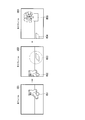
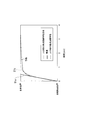
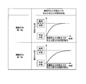
- FIG. 51 is an example of temporal characteristics from the start of focus adjustment to the focused state.
- the vertical axis represents the focal position and the horizontal axis represents time.
- the focus adjustment characteristic 51a is a focus adjustment characteristic when focus adjustment is performed at a constant speed.
- the focus adjustment characteristic 51b is a physical focus adjustment characteristic of the human eyeball.
- the focus adjustment characteristic 51c is a focus adjustment characteristic that approximates the physical focus adjustment characteristic of a human eyeball.
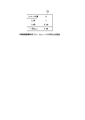
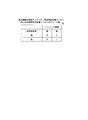
- FIG. 52 shows the result of the subjective evaluation of the viewer in 11 stages of preferred: 10 points, neither: 5 points, unfavorable: 0 points.
- the result shown in FIG. 52 is an evaluation result of a moving image in which focus adjustment is performed with behavior based on the three focus adjustment characteristics shown in FIG. 51 as an example.
- the focus adjustment to which the physical focus adjustment characteristic of the human eyeball shown in FIG. 51 is applied or the focus adjustment characteristic to which the physical focus adjustment characteristic approximating the physical focus adjustment characteristic of the human eyeball shown in FIG. 51 is applied. It was found that adjustment is preferred when watching movies, and the latter is more preferred. This is thought to be because the subjective focus adjustment that humans perceive with their instinct is not the physical focus adjustment characteristic of the eyeball but is close to the focus adjustment characteristic that approximates it. Also, in the human subjective focus adjustment, the person does not try to see all subjects in an appropriate focus state, but considers both the state of viewing and the information of the object to be viewed in his head.
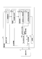
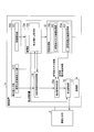
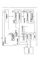
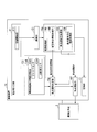
- FIG. 1 is a schematic block diagram showing the configuration of the imaging apparatus 1 according to the first embodiment of the present invention.
- the imaging apparatus 1 includes an imaging unit 12, a human subjective focus adjustment related information acquisition unit 13, and a focus adjustment determination unit 15.
- the imaging optical system 2 guides light from the subject to the imaging unit 12 and forms an image of the subject with the imaging element of the imaging unit 12.
- the imaging optical system 2 can be detached from the imaging device 1 as an example. Note that the imaging optical system 2 may be fixed to the imaging device 1.
- the imaging unit 12 captures an image of the subject formed by the imaging optical system 2 to generate a moving image signal, and outputs the generated moving image signal to the human subjective focus adjustment related information acquisition unit 13.
- the human subjective focus adjustment related information acquisition unit 13 acquires at least information related to human subjective focus adjustment from the moving image signal.
- information related to human subjective focus adjustment is determined, for example, from inter-frame change information regarding changes occurring between two or more frames, and intra-frame information that is information within one frame included in a moving image signal.
- Information relating to the situation for example, the state and movement of the imaging device
- the situation of the subject being viewed for example, the movement and color of the subject.
- the degree of attention to the subject of focus adjustment varies depending on the situation of shooting and the situation of the subject being viewed. Therefore, it can be said that these pieces of information are information related to human subjective focus adjustment.
- FIG. 57 is a schematic block diagram showing the configuration of the imaging apparatus 1 in this case.
- the human subjective focus adjustment related information acquisition unit 13 includes an interframe change information acquisition unit 13a that acquires the interframe change information and an intraframe information acquisition unit 14a that acquires information about the intraframe information. Prepare.
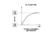
- the information related to the human subjective focus adjustment is not limited to the above, but is shown in the physical focus adjustment characteristics (the movement of the crystalline lens) of the human eye as shown in FIG. It may be an approximation of the physical focus adjustment characteristics of the human eyeball.
- information may be stored in advance in a memory (not shown) of the imaging apparatus 1 and information may be acquired by referring to the memory when necessary.
- the focus adjustment determination unit 15 determines the behavior of the focus adjustment using information related to human subjective focus adjustment. Thereby, it is possible to adjust the focus according to the ease of attention of the viewer and the movement of the eyeball. For this reason, the imaging apparatus 1 can provide a moving image that the photographer (or the viewer) looks more favorably, so that the satisfaction of the moving image of the photographer or the viewer can be improved.
- the focus adjustment determination unit 15 determines the behavior of the focus adjustment as follows in accordance with information related to human subjective focus adjustment. (1) The behavior of the focus adjustment is determined by determining the acceleration and the speed in the focus adjustment for bringing the subject into focus according to the information related to the subjective focus adjustment of the person.
- the behavior of the focus adjustment is determined by determining the timing for starting deceleration in the focus adjustment for bringing the subject into focus according to the information related to the subjective focus adjustment of the person.
- the behavior of the focus adjustment is determined by determining the timing for starting the focus adjustment in the focus adjustment for bringing the subject into focus in accordance with the information related to the human subjective focus adjustment.
- the behavior of the focus adjustment is determined by determining whether or not the focus adjustment can be driven according to information related to the subjective focus adjustment of the person.
- the terms “suppress focus adjustment” and “promote focus adjustment” are used, which are defined as follows. Suppress focus adjustment: Prohibit focus adjustment, or make it easy to be prohibited or slow (decrease focus adjustment speed / acceleration). Accelerate focus adjustment: perform or facilitate focus adjustment, or make it faster than when suppressing focus adjustment (to increase the speed / acceleration of focus adjustment).
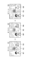
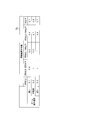
- FIG. 2 is a diagram illustrating scenes assumed as shooting conditions in each embodiment.
- the subject that the photographer wants to focus on changes.
- the imaging apparatus does not vary (only subject variation).
- there is no subject change only the change of the imaging device.
- the scenes assumed in the respective embodiments are assumed.
- a scene in which a subject that was not initially imaged moves and appears in the angle of view is assumed.
- the second embodiment assumes a scene in which there are a plurality of subjects in the screen in advance, and the subject to be noticed (the subject to be focused) changes as the brightness of the subject changes.
- the third embodiment assumes a scene in which a subject moves and disappears from the screen, and another subject that has been hidden appears.
- a scene is assumed in which a subject to be imaged within an angle of view changes as the imaging apparatus physically moves.
- Example 1 Next, Example 1 will be described.
- inter-frame change information relating to changes occurring between two or more frames and intra-frame information which is information contained in one frame included in a moving image signal, are acquired as information related to human subjective focus adjustment.
- FIG. 3 is a diagram for explaining an example of a shooting scene in the first embodiment. In the figure, a scene in which a certain subject appears from the right side of the screen and moves to the center of the screen.
- the image area of the subject does not exist in the image G11 (N is a positive integer) of N + 1 frames.
- N is a positive integer
- the image area R12 of the subject is shown on the right side toward the image G12.
- the image region R13 of the subject is shown in the center of the image G13.
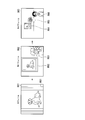
- FIG. 4 is a schematic block diagram illustrating the configuration of the imaging device 1a according to the first embodiment.
- the imaging apparatus 1a includes an imaging optical system 2, a photographer input unit 11, an imaging unit 12a, an image processing unit 10, a focus adjustment determination unit 15a, a focus adjustment unit 16, and a recording unit 17.
- the imaging optical system 2 guides light from the subject to the imaging unit 12a, and forms an image of the subject with an imaging element included in the imaging unit 12a.
- the image sensor generates a moving image signal of the subject.
- the imaging optical system 2 can be removed from the imaging device 1a as an example. Note that the imaging optical system 2 may be fixed to the imaging device 1a.
- the configuration of the imaging optical system 2 is the same in the following embodiments.
- the photographer input unit 11 receives a photographer's input.
- the photographer input unit 11 includes a recording start button 111 that receives a photographing start instruction from the photographer.
- the imaging unit 12a generates a moving image signal by converting light incident from the subject via the imaging optical system 2 into an electrical signal at a predetermined shutter speed.
- the imaging unit 12 a includes a focus adjustment amount acquisition unit 121.
- the image processing unit 10 generates image data from the moving image signal supplied from the imaging unit 12a, and causes the recording unit 17 to record the generated image data.
- the image processing unit 10 includes an inter-frame change information acquisition unit 13a and an in-frame information acquisition unit 14a.
- the inter-frame change information acquisition unit 13a includes a subject motion information acquisition unit 131
- the intra-frame information acquisition unit 14a includes a subject size information acquisition unit 141.
- the imaging apparatus 1a sets an area for focus adjustment in advance.
- the imaging device 1a performs face detection to extract a detected face that is an image area of the face, and the extracted detected face is set as an area for focus adjustment.
- the imaging apparatus 1a holds a facial feature database in which images of characteristic parts (for example, eyes and mouth) in the face are stored.
- the image processing unit 10 extracts an image region in an image obtained by imaging, and compares the extracted image region with an image stored in the facial feature database, thereby obtaining the face of the subject. Detect the image area.
- the focus adjustment unit 16 can perform focus adjustment on the detected face by using the detected image area of the face of the subject as the detected face.
- the recording start button 111 receives a moving image recording start instruction from the photographer, and outputs start instruction information indicating the received start instruction to the imaging unit 12a.
- the imaging unit 12a receives the start instruction information from the photographer input unit 11, the imaging unit 12a converts the light incident from the subject via the imaging optical system 2 into an electrical signal at a predetermined shutter speed, thereby converting the moving image signal. Generate. Thereby, the imaging unit 12a can start moving image recording in accordance with a photographer's instruction.
- the imaging unit 12a outputs the generated moving image signal to the image processing unit 10.
- the imaging unit 12a includes, for example, an imaging element that is used as a phase difference element in which a part of a plurality of light receiving elements arranged on the image plane detects a phase difference.
- the imaging unit 12a splits the light incident from the subject into a plurality of light beams, and causes the split light beams to enter different phase difference elements. Thereby, the phase difference element converts the incident light into an electric signal.
- the focus adjustment amount acquisition unit 121 acquires a focus adjustment amount for bringing the focus adjustment target area into a focused state based on the information on the set focus adjustment area, and uses the acquired focus adjustment amount as the focus adjustment unit. 16 is output.
- the focus adjustment amount is acquired from a phase difference element arranged on the image plane of the imaging element of the imaging unit.
- the focus adjustment amount acquisition unit 121 acquires the focus adjustment amount by observing the phase difference between the electrical signals obtained by conversion by different phase difference elements.
- the focus adjustment amount acquisition unit 121 outputs the acquired focus adjustment amount to the focus adjustment unit 16.
- the moving speed is, for example, the face center speed (pixel / Frame).
- the subject motion information acquisition unit 131 may detect the center position of the detected face in one frame and the center position of the detected face in the next frame, and calculate the number of moving pixels of the center position of the detected face as the center speed of the face. Good.
- the subject motion information acquisition unit 131 is not limited to this, the distance from the imaging device to the subject (this distance is detected from the phase difference element as an example), the angle of view, and the lateral direction of the imaging element.
- the horizontal width of the imaging range in real space may be calculated from the length.
- the subject motion information acquisition unit 131 sets the moving pixel count (pixel) at the center position of the detected face to the horizontal width of the imaging range in the calculated real space by the horizontal pixel count (eg, 1024) of the captured image. By multiplying by the divided number, the number of moving pixels at the center position of the detected face may be converted into the center speed (m / Frame) of the face in real space.
- the subject movement speed as well as the subject size is compared with an arbitrary threshold value stored in advance in a memory (not shown) in the image pickup apparatus 1a, so that it is "substantially faster” Although it is determined as one of “fast”, “medium”, and “slow”, the acquired movement speed (for example, pixel / frame) of the subject may be used as it is.
- the subject motion information acquisition unit 131 outputs subject motion speed information indicating the motion speed of the subject to the focus adjustment determination unit 15a.
- the subject size information acquisition unit 141 acquires subject size information indicating the size of the subject as in-frame information, and outputs the acquired subject size information to the focus adjustment determination unit 15a.
- An example of the specific processing will be described.
- a first threshold value for separating “extra large (extra extent from the screen)” and “large”, “large” and “large” A second threshold value for separating “medium” and a third threshold value for separating “medium” and “small” are stored in advance.
- “extra large”, “large”, “medium”, and “small” are classifications of the size of the subject.
- the subject size information acquisition unit 141 acquires, for example, the size of the detected face as the size of the subject, and the acquired subject size and the first threshold value and the second threshold value stored in a memory (not shown). , And the third threshold value, the subject size is determined to be “extra large”, “large”, “medium”, or “small”.
- the present invention is not limited to this, and for example, information on the number of pixels of the detected face may be used as it is.
- the size of the subject is not limited to the size of the detected face, and the subject size information acquisition unit 141 determines the background region and the non-subject subject region by a known technique such as figure-ground determination, and performs focus adjustment.
- the size of the subject area in the vicinity may be the size of the subject.
- the vicinity of the area where the focus adjustment is performed includes, for example, an area where the focus adjustment is performed, and also includes pixels which are separated from the area by a predetermined number of pixels.
- the subject size information acquisition unit 141 uses the color of each image area or the distance of the image area from the imaging device (this distance is detected from the phase difference element as an example), Of the image areas determined and determined as “figure”, the size of the image area closest to the above-described focus adjustment area (here, as an example, the detected face) may be the size of the subject.
- the subject can be arbitrarily selected.
- the photographer input unit 11 accepts an input of the subject selection by the photographer, and the subject size information acquisition unit 141 receives the input accepted by the photographer input unit 11.
- Subject size information may be acquired for the subject shown.
- the subject size information acquisition unit 141 acquires the subject size in the frame as subject size information as an example.
- the subject size information is obtained by the following processing. May be acquired and used as subject size information.
- (1) Object physical size information acquisition process 1 As an example, the subject size information acquisition unit 141 may perform triangulation using the previous frame information to obtain the physical subject size.
- (2) Acquisition process 2 of physical size information of the subject The imaging apparatus 1a stores an average size of a general subject in a memory (not shown) in advance.
- the imaging device 1a may perform object recognition processing of a subject to be imaged using a known technique and specify what the subject to be imaged is. Then, as an example, the subject size information acquisition unit 141 may obtain the average size information of the subject stored in advance as the physical size of the subject.
- the focus adjustment determination unit 15 a determines the behavior of brightness adjustment from the subject size information acquired by the subject size information acquisition unit 141 and the subject movement speed information acquired by the subject motion information acquisition unit 131.
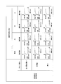
- a memory (not shown) in the imaging apparatus 1a stores a table as shown in FIG. 5 in which one brightness adjustment speed suppression coefficient ⁇ is associated with a set of a subject size and a subject movement speed. Has been.
- the focus adjustment determination unit 15a reads the focus adjustment speed suppression coefficient ⁇ corresponding to the set of the acquired subject size information and the acquired subject movement speed information with reference to the table of FIG.
- a reference focus adjustment speed V base at the time of moving image shooting is stored in advance in a memory (not shown).
- the focus adjustment determination unit 15a reads the reference focus adjustment speed V base from the memory, and determines the actual focus adjustment speed V control according to the following equation (1).
- V control V base ⁇ ⁇ (1)
- the focus adjustment determination unit 15a changes the speed of focus adjustment. For example, the focus adjustment is performed by selecting either “to operate” or “forbid” the focus adjustment. It may be suppressed.
- the focus adjustment determination unit 15 a outputs the determined focus adjustment behavior to the focus adjustment unit 16.
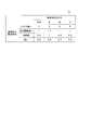
- FIG. 5 is an example of a table for determining the focus adjustment speed suppression coefficient ⁇ .
- the focus adjustment speed suppression coefficient ⁇ is associated with each set of the movement speed of the subject and the size of the subject.
- the focus adjustment speed suppression coefficient ⁇ tends to be small, and is slower than that (“somewhat fast”, “medium”, “slow” in FIG. 5). In the case), the slower the movement speed of the subject, the smaller the focus adjustment speed suppression coefficient ⁇ .
- the moving speed of the subject is higher than a certain level, the focus adjustment is suppressed, and when the speed is lower than a certain level, the slower the speed, the more the focus adjustment is suppressed.
- a video can be provided.
- the focus adjustment speed suppression coefficient ⁇ tends to increase when the subject size is “large” and “medium”, and tends to decrease in the order of “small” and “extra large”. Is done.
- the imaging apparatus 1a can be controlled by the photographer (or the viewer) by suppressing the focus adjustment. It is possible to provide a video that looks more like.
- the focus adjustment unit 16 controls the focus adjustment optical system of the imaging optical system 2 based on the focus adjustment behavior (focus adjustment speed) determined by the focus adjustment determination unit 15a to adjust the focus.
- the focus adjustment optical system of the imaging optical system 2 is controlled to perform focus adjustment.
- the present invention is not limited to this process.
- the reference “Light Field Photography with a Hand-Held Plenoptic Camera” Ren Ng et al. Stanford Tech Report CTSR 2005-02 ” is used to shoot using an imaging optical system, etc., and after image processing, an image focused on the area to be focused is generated by image processing. good.
- the imaging optical system having the structure shown in the above-mentioned reference is an imaging optical system having the structure of a light field camera.
- a microlens array is attached between the main lens of the imaging apparatus and the imaging element, and the imaging optical system can be viewed from many directions. It is an optical system that simultaneously records the light beams. As a result, the focal point can be freely changed from the background to the front after shooting.
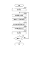
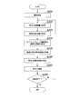
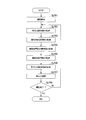
- FIG. 6 is a flowchart illustrating an example of a processing flow of the imaging apparatus 1a according to the first embodiment.
- Step S101 First, when the recording start button 111 is pressed, the imaging unit 12a starts shooting.
- Step S102 Next, the focus adjustment amount acquisition unit 121 acquires a focus adjustment amount.
- Step S103 Next, the subject size information acquisition unit 141 acquires subject size information.
- Step S104 Next, the subject motion information acquisition unit 131 acquires subject motion speed information as an example of subject motion information.
- Step S105 the focus adjustment determination unit 15a determines the behavior of the focus adjustment using the subject movement speed information and the subject size information.
- Step S106 the focus adjusting unit 16 adjusts the focus according to the determined behavior of the focus adjustment.
- the imaging unit 12 a determines whether or not the shooting has ended based on information received by the photographer input unit 11. If the shooting has not ended (NO), the process returns to step S102. In the case of the end of shooting (YES), the imaging device 1a ends the process. Above, the process of this flowchart is complete
- the focus adjustment determination unit 15a determines the behavior of the focus adjustment using, for example, the subject movement speed information and the subject size information. For example, in a scene where a subject (a person in the example of FIG. 3) appears from the right side of the image capturing apparatus 1a without movement and change, and the moving speed of the moving subject is too fast in a scene where focus adjustment is performed, Since the viewer (viewer) does not tend to determine that the subject is in focus, the focus adjustment determination unit 15a determines the focus adjustment behavior so as to suppress the focus adjustment. However, once it is determined that focus adjustment is to be performed (when the movement speed of the subject is below a certain level), the slower the movement speed of the subject, the more gradual focus adjustment tends to be preferred.
- the determination unit 15a determines the focus adjustment behavior so as to suppress the focus adjustment as the moving speed is slower.
- the sixth threshold value in which the size of the moving subject is determined in advance. If it is smaller or larger than the seventh threshold value, the focus adjustment determination unit 15a determines the focus adjustment behavior to suppress the focus adjustment.
- the seventh threshold is larger than the sixth threshold.
- the subject motion information acquisition unit 131 acquires subject motion speed information as subject motion information.
- the subject motion amount and the like are also included. May be obtained, and the behavior of the focus adjustment may be determined ⁇ Modification 1: Subject movement amount>
- the subject motion information acquisition unit 131 in FIG. 4 may acquire “subject motion amount” instead of “subject motion speed”.
- the subject motion information acquisition unit 131 may acquire the amount of motion of the subject by image processing as well as the motion speed of the subject.
- the amount of movement referred to here may be the amount of movement after an arbitrary subject starts moving, or may be the amount of movement between an arbitrary number of frames.
- the subject movement information acquisition unit 131 acquires the amount of movement from a frame that appears at the angle of view as an example.
- the larger the amount of movement from when the subject appears at the angle of view the more the subject moves after a certain distance within the angle of view
- the photographer (or viewer) focuses on the moving subject. It is easy to judge that you want to be in a state. Accordingly, the focus adjustment determination unit 15a may determine the behavior of the focus adjustment so as to suppress the focus adjustment operation as the subject movement amount is smaller.
- the subject movement information acquisition unit 131 in FIG. 4 may acquire “differences in movement states of a plurality of subjects” instead of “subject movement speed”.
- the subject movement information acquisition unit 131 acquires the difference information (for example, the difference in the moving direction) of the movement states of a plurality of subjects, for example, by image processing using the following processing method, as with the speed of the subject.
- the subject motion information acquisition unit 131 detects the face of the subject, and acquires motion information for all detected faces when a plurality of faces are detected.
- the subject movement information acquisition unit 131 acquires the difference information (here, the difference in the movement direction) of the plurality of subjects, and the focus adjustment determination unit 15a includes the difference in the movement state of the plurality of subjects (here, the movement direction). It is preferable to determine the behavior of the focus adjustment so as to suppress the focus adjustment operation so that there is no difference.
- the difference information of the movement direction is acquired as the difference information of the movement states of the plurality of subjects, but the subject movement information acquisition unit 131 may acquire the difference information of the movement speed, the difference of the movement amount, and the like.
- the focus adjustment determination unit 15a may determine the behavior of the focus adjustment using the difference information of the movement speed or the difference of the movement amount. For example, the focus adjustment determination unit 15a may promote focus adjustment when a difference in moving speed of a certain subject exceeds a predetermined reference as compared to other subjects. As a result, when there is a large difference in moving speed between one subject and another, the viewer will pay attention to the subject and want to see the subject quickly and clearly. Satisfaction can be improved.
- the focus adjustment determination unit 15a may suppress focus adjustment.
- the imaging apparatus 1a Can provide a moving image that looks better for the photographer (or viewer).
- the subject motion information acquisition unit 131 in FIG. 4 may acquire “subject motion type information” instead of “subject motion speed”.
- the movement type information of the subject is, for example, information regarding the movement when “walking” or information regarding the movement when “running” when the subject is a human being.
- the subject motion information acquisition unit 131 acquires subject motion type information, similar to the subject speed, by image processing using, for example, the following processing method.
- Step 1 Information about a motion pattern on a face area image when a human is walking and information about a motion pattern on a face area image when a human is running are captured as reference information. Stored in advance in the memory of the device 1a.
- Procedure 2 When the photographer starts photographing, the imaging unit 12a generates a moving image signal of the subject as described above.
- Procedure 3 The subject motion information acquisition unit 131 detects a face area by performing face recognition processing on the moving image signal generated by the imaging unit 12a.
- Procedure 4 The subject motion information acquisition unit 131 tracks the detected face area to acquire information on the motion of the face area on the image.
- Procedure 5 Humans in a plurality of movement patterns (movement patterns when walking, movement patterns while running, etc.) that the subject movement information acquisition unit 131 stores as reference information in the memory in the above-described procedure 1
- the information on the movement of the face area on the image is collated with the information on the movement of the face area detected in the above-described procedure 4, so that the plurality of motion patterns stored in the procedure 1 are acquired in the procedure 4.
- the movement of the pattern that most closely approximates the movement is identified as information relating to the current movement of the subject (movement of the human face). For example, if the movement acquired in step 4 is the closest to the movement pattern of the face area when a person is running among the movement patterns stored in step 1, the subject movement information acquisition unit 131 may It is determined that the movement is a movement when a human is running.
- the procedure for determining the movement when the subject is “walking” and the movement when the subject is “running” by image processing is not limited to the above steps 1 to 5. . Since people tend to want to focus faster when the subject is running than when they are walking, it is better to determine the focus adjustment behavior to facilitate focus adjustment.
- the subject movement information acquisition unit 131 in FIG. 4 may acquire “subject movement direction” instead of “subject movement speed”.
- the subject motion information acquisition unit 131 acquires subject motion type information as well as the subject speed by image processing. As a human sense, there is a tendency to focus faster when the subject moves in a horizontal and vertical direction than a subject that moves in an oblique direction, so focus adjustment is promoted when the subject moves in a horizontal direction. It is better to determine the behavior of the focus adjustment.
- subject movement information is acquired as subject change information, but the following information may be acquired to determine the focus adjustment behavior.
- the subject movement information acquisition unit 131 in FIG. 4 may be replaced with a subject deformation information acquisition unit, and the subject deformation information acquisition unit may acquire “subject color change information” instead of “subject movement speed”.
- the subject color change information is information indicating the subject color change. For example, when the subject changes color (such as changing the background on the stage or changing the subject), the ease of drawing attention to the subject changes depending on the amount or speed of change in color.
- the processing method and effect for determining the behavior of the focus adjustment are the same as in the case of acquiring subject movement information. Accordingly, the subject deformation information acquisition unit may acquire the subject color change information, and the focus adjustment determination unit 15a may determine the behavior of the focus adjustment.
- the focus adjustment determining unit 15a decreases as the color change amount or the color change speed of a certain subject decreases. Focus adjustment may be suppressed. Further, when the color change amount or the color change speed of a certain subject is equal to or less than a predetermined reference, the viewer does not pay attention to the subject, so the focus adjustment determination unit 15a may suppress the focus adjustment.
- the subject movement information acquisition unit 131 in FIG. 4 may replace the “subject deformation information acquisition unit”, and the subject deformation information acquisition unit may acquire “subject deformation information” instead of “subject movement speed”.
- the ease of drawing attention to the subject varies depending on the deformation speed or amount of deformation of the subject when the subject is deformed (such as a balloon is inflated).
- the process and effect for determining the behavior of the focus adjustment are the same as in the case of acquiring subject movement information. Therefore, the subject deformation information acquisition unit may acquire the subject deformation information, and the focus adjustment determination unit 15a may determine the behavior of the focus adjustment.
- the focus adjustment determination unit 15a may suppress the focus adjustment.
- Inter-frame signal value change amount of moving image signal to be captured The subject motion information acquisition unit 131 in FIG. 4 is changed to an inter-frame signal change amount acquisition unit of a moving image signal to be captured, and the inter-frame signal change amount acquisition unit of the captured video signal is not a motion speed of the subject.
- the inter-frame signal value change amount of the moving image signal to be captured may be acquired.
- the focus adjustment determination unit 15a may calculate the difference between the corresponding pixel values for all the pixels, and acquire the sum of the absolute values of the calculated differences as the inter-frame signal value change amount.
- An inter-frame signal value change amount (a change rate or the like can be obtained therefrom) in the captured moving image signal may be acquired.
- the process and effect for determining the behavior of the focus adjustment are the same as in the case of acquiring subject movement information.
- the case where the inter-frame signal value change amount is large is a case where panning or a large amount of change occurs in the screen. If the focus adjustment is further performed in this state, the appearance of the moving image is deteriorated. Therefore, the viewer does not like that the focus adjustment is performed in this state. Therefore, for example, the focus adjustment determination unit 15a may suppress the focus adjustment as the inter-frame signal value change amount is larger. Further, the focus adjustment determination unit 15a may suppress focus adjustment when the amount of change in the inter-frame signal value exceeds a predetermined reference.
- ⁇ Modification 8 Tracking information of an arbitrary point or area of a frame image>
- the subject movement information acquisition unit 131 in FIG. 4 may be replaced with a tracking information acquisition unit, and the tracking information acquisition unit may acquire tracking information of an arbitrary point or region of the frame image instead of “subject movement speed”.
- the frame image is an image obtained for each frame from the moving image signal.
- the tracking information acquisition unit may acquire tracking information of an arbitrary characteristic point (corner, edge, etc.) or an arbitrary area in an image that is not limited to a face obtained by a known technique.
- the process and effect for determining the behavior of the focus adjustment are the same as in the case of acquiring subject movement information.
- the tracking information is, for example, a change amount in the feature amount space by a known tracking technique.
- the focus adjustment determination unit 15a suppresses the focus adjustment. Also good. As a result of tracking, if the tracking target moves too fast or does not move very much, the viewer does not pay attention to the tracking target. Therefore, for example, when the movement speed of the tracking target exceeds a predetermined first threshold or when the movement amount (or movement speed) of the tracking target is equal to or less than a predetermined second threshold, the focus adjustment determination unit 15a Adjustment may be suppressed.
- the second threshold value is smaller than the first threshold value.
- the focus adjustment determination unit 15a may suppress the focus adjustment as the movement amount of the tracking target or the tracking target is smaller.
- the focus adjustment behavior is determined using information related to inter-frame change and information within one frame as information related to human subjective focus adjustment.
- the behavior of the focus adjustment may be corrected using “information relating to setting for photographing” or “information relating to which phase difference element is used” (specific examples are shown below). These pieces of information cannot be said to be information related to human subjective focus adjustment, but are factors that affect preferred focus adjustment when watching moving images. It is possible to determine a more preferable focus adjustment behavior by additionally acquiring these pieces of information and correcting the determined focus adjustment behavior using the acquired information.
- the information regarding which phase difference element is used is obtained by using which phase difference element to perform the focus adjustment using the phase difference signal as in this embodiment. It can be acquired when it is possible to vary the operation.
- the focus adjustment determination unit 15a temporarily determines the behavior of the focus adjustment using the subject movement information acquired as information related to the change between frames and the subject size information acquired as information within one frame.
- the behavior of the focus adjustment may be determined by correcting the temporarily determined behavior of the focus adjustment using the third information.
- FIG. 7 is a schematic block diagram illustrating a configuration of the imaging device 1b according to Modification 9.
- symbol is attached
- the imaging setting information acquisition unit 18 is added to the configuration of the imaging apparatus 1a in the first embodiment in FIG. 4, and the focus adjustment determination unit 15a is changed to the focus adjustment determination unit 15b. It has been done.
- the shooting setting information acquisition unit 18 acquires shooting setting information, which is information related to shooting settings, and outputs the acquired information related to shooting settings to the focus adjustment determination unit 15b.
- the shooting setting information acquisition unit 18 acquires ISO sensitivity setting information of the imaging apparatus 1b as shooting setting information.
- the ISO sensitivity of the imaging device 1b is high, noise in the screen increases and the appearance of the moving image becomes troublesome. In such a state, since further changes in the moving image are easily disliked, it is better to suppress the focus adjustment when the sensitivity is high.
- a table in which the ISO sensitivity and the focus adjustment suppression coefficient ⁇ are associated with each other is stored in advance in a memory (not shown).
- the higher the ISO sensitivity the smaller the focus adjustment suppression coefficient ⁇ .
- the focus adjustment determination unit 15b refers to a memory table (not shown) and reads the focus adjustment suppression coefficient ⁇ corresponding to the ISO sensitivity of the imaging device 1a to obtain the focus adjustment suppression coefficient ⁇ . decide. Then, the focus adjustment determination unit 15b determines the final focus adjustment behavior, for example, according to the following equation (2).
- V control V base ⁇ ⁇ ⁇ ⁇ (2)
- Equation (2) is an equation that corrects the behavior of the focus adjustment determined by Equation (1) described above.
- the focus adjustment determination unit 15b corrects the behavior of the focus adjustment so that the focus adjustment is suppressed as the focus adjustment suppression coefficient ⁇ is smaller. That is, as the ISO sensitivity is higher, the focus adjustment determination unit 15b decreases the focus adjustment suppression coefficient ⁇ in Expression (2) and corrects the behavior of the focus adjustment so that the focus adjustment is suppressed.
- the shooting setting information acquisition unit 18 acquires shutter speed setting information of the imaging device 1b as shooting setting information. If the shutter speed setting of the imaging device 1b is faster than the frame rate at the time of moving image capturing, the motion of the moving image is not smooth (the moving image looks like a flip book). Therefore, for example, the focus adjustment determination unit 15b corrects the behavior of the focus adjustment so as to suppress the focus adjustment as the shutter speed setting of the imaging device 1b is faster than the frame rate at the time of moving image capturing.
- FIG. 8 is an example of a table T2 in which the shutter speed and the focus adjustment suppression coefficient ⁇ stored in a memory (not shown) are associated with each other.
- the focus adjustment suppression coefficient ⁇ decreases as the shutter speed increases.
- the focus adjustment determination unit 15b refers to a table T2 (see FIG. 8) stored in a memory (not shown), and reads the focus adjustment suppression coefficient ⁇ corresponding to the shutter speed setting.
- the focus adjustment suppression coefficient ⁇ is determined.
- the focus adjustment determination unit 15b corrects the behavior of the focus adjustment according to Expression (2), as in Example 1. Thereby, the focus adjustment determination unit 15b corrects the behavior of the focus adjustment so as to suppress the focus adjustment because the focus adjustment suppression coefficient ⁇ in the equation (2) becomes smaller as the shutter speed setting is faster.
- the shooting setting information acquisition unit 18 acquires F value setting information of the imaging optical system 2 attached to the imaging device 1b as shooting setting information. If the F-number setting of the imaging optical system 2 attached to the imaging device 1b is small, the depth of field becomes shallow. When the depth of field is shallow, it is easy to focus on one subject. Therefore, for example, the focus adjustment determination unit 15b corrects the behavior of the focus adjustment so as to suppress the focus adjustment as the F value setting of the imaging device 1b is larger.
- a table in which the F value and the focus adjustment suppression coefficient ⁇ are associated with each other is stored in advance in a memory (not shown).
- the focus adjustment suppression coefficient ⁇ decreases as the F value increases.
- the focus adjustment determination unit 15b refers to a memory table (not shown) and reads the focus adjustment suppression coefficient ⁇ corresponding to the F value to determine the focus adjustment suppression coefficient ⁇ .
- the focus adjustment determination unit 15b corrects the behavior of the focus adjustment according to Expression (2), as in Example 1. Thereby, the focus adjustment determination unit 15b corrects the behavior of the focus adjustment so as to suppress the focus adjustment because the focus adjustment suppression coefficient ⁇ in the equation (2) decreases as the F value increases.
- the shooting setting information acquisition unit 18 acquires the focal length setting information of the imaging optical system 2 attached to the imaging device 1b as shooting setting information.
- the focus adjustment determination unit 15b determines the behavior of the focus adjustment so that the focus adjustment is suppressed as the focal length setting of the imaging optical system 2 attached to the imaging device 1b is shorter.
- a table in which a focal length and a focus adjustment suppression coefficient ⁇ are associated with each other is stored in advance in a memory (not shown).
- the focus adjustment determination unit 15b refers to a memory table (not shown) and reads the focus adjustment suppression coefficient ⁇ corresponding to the focal length to determine the focus adjustment suppression coefficient ⁇ .
- the focus adjustment determination unit 15b corrects the behavior of the focus adjustment according to Expression (2), as in Example 1. Thereby, the focus adjustment determination unit 15b corrects the behavior of the focus adjustment so as to suppress the focus adjustment because the focus adjustment suppression coefficient ⁇ in the equation (2) becomes smaller as the focal length is shorter.
- the shooting setting information acquisition unit 18 acquires setting information of image processing of the imaging device 1b as shooting setting information.
- NR noise reduction
- a table in which the NR intensity and the focus adjustment suppression coefficient ⁇ are associated with each other is stored in advance in a memory (not shown).
- the focus adjustment suppression coefficient ⁇ decreases as the NR intensity decreases.
- the focus adjustment determination unit 15b refers to a memory table (not shown) and reads the focus adjustment suppression coefficient ⁇ corresponding to the NR intensity to determine the focus adjustment suppression coefficient ⁇ .
- the focus adjustment determination unit 15b corrects the behavior of the focus adjustment according to Expression (2), as in Example 1. Thereby, the focus adjustment determination unit 15b decreases the focus adjustment suppression coefficient ⁇ in the equation (2) as the NR intensity is lower, and thus corrects the behavior of the focus adjustment so as to suppress the focus adjustment.
- the shooting setting information acquisition unit 18 acquires the presence / absence or intensity of an expression enhancement process as setting information for image processing of the imaging apparatus 1b, which is an example of shooting setting information.
- the expression enhancement processing is, for example, processing for enhancing the saturation of the entire image and enhancing the captured image colorfully and impressively. The more the expression enhancement processing is applied, the stronger the irritation to the eyes in the screen, so it is better to suppress the focus adjustment. Accordingly, the focus adjustment determination unit 15b determines the behavior of the focus adjustment so as to suppress the focus adjustment, for example, as the degree to which the expression enhancement process is applied is larger.
- the focus adjustment determination unit 15b determines the behavior of the focus adjustment so as to suppress the focus adjustment, for example, as the intensity of the expression enhancement process is higher. For example, the focus adjustment determination unit 15b determines the behavior of the focus adjustment so as to further suppress the focus adjustment in which the expression emphasis process is not performed.
- a table in which the strength of the expression enhancement process and the focus adjustment suppression coefficient ⁇ are associated with each other is stored in advance in a memory (not illustrated).
- the focus adjustment suppression coefficient ⁇ decreases as the strength of the expression enhancement process increases.
- the intensity of the expression enhancement process is 0.
- the focus adjustment determination unit 15b refers to a memory table (not shown) and reads the focus adjustment suppression coefficient ⁇ corresponding to the intensity of the expression emphasis process to thereby adjust the focus adjustment suppression coefficient ⁇ . To decide.
- the focus adjustment determination unit 15b corrects the behavior of the focus adjustment according to Expression (2), as in Example 1. Accordingly, the focus adjustment determination unit 15b corrects the behavior of the focus adjustment so as to suppress the focus adjustment because the focus adjustment suppression coefficient ⁇ in the expression (2) becomes smaller as the strength of the expression enhancement process is higher.
- FIG. 9 is a flowchart illustrating an example of a processing flow of the imaging apparatus according to Modification 9.
- Step S201 First, when the recording start button 111 is pressed, the imaging unit 12a starts shooting.
- Step S202 Next, the focus adjustment amount acquisition unit 121 acquires a focus adjustment amount.
- Step S203 Next, the subject size information acquisition unit 141 acquires subject size information.
- Step S204 Next, the subject motion information acquisition unit 131 acquires subject motion speed information as an example of subject motion information.
- the shooting setting information acquisition unit 18 acquires shooting setting information.
- the focus adjustment determination unit 15b determines the behavior of the focus adjustment using the subject movement speed information, the subject size information, and the shooting setting information.
- Step S207 Next, the focus adjustment unit 16 adjusts the focus according to the determined focus adjustment behavior.
- Step S208 Next, the imaging unit 12a determines whether or not the photographing is finished. If the shooting has not ended (NO), the process returns to step S202. In the case of shooting end (YES), the imaging device 1b ends the process. Above, the process of this flowchart is complete
- the focus adjustment determination unit 15b determines the focus adjustment behavior using, for example, the shooting setting information in addition to the subject movement information and the subject size information. At that time, for example, the imaging apparatus 1b determines the behavior of the focus adjustment so as to suppress the focus adjustment as the phase difference elements are used at sparse intervals. Thereby, since the imaging device 1b can correct the focus adjustment behavior with the shooting setting information, it is possible to perform the focus adjustment according to the ease of the viewer's attention. Therefore, the imaging device 1b can provide a moving image that looks better for the photographer (or the viewer).
- FIG. 10 is a schematic block diagram illustrating a configuration of the imaging device 1c according to Modification Example 10.
- symbol is attached
- the configuration of the imaging apparatus 1c in the modification 10 is the same as that of the imaging apparatus 1a in the first embodiment shown in FIG. 4 except that a phase difference use state acquisition unit 19 is added and the photographer input unit 11 is added to the photographer input unit 11b. It has been changed.
- the photographer input unit 11b has a use phase difference pixel input unit 112 added to the photographer input unit 11 of the first embodiment shown in FIG.
- Modification 10 it is assumed that when the focus adjustment amount is acquired using the phase difference signal, it is possible to vary which phase difference element is used to acquire the focus adjustment amount.
- the user inputs a used phase difference pixel that is a pixel of the phase difference element to be used.
- the used phase difference pixel input unit 112 receives an input of the used phase difference pixel by the user, and outputs the received input information to the phase difference use state acquisition unit 19 and the focus adjustment amount acquisition unit 121.
- the phase difference usage status acquisition unit 19 acquires phase difference element usage status information regarding which phase difference element is used from the input information input from the usage phase difference pixel input unit 112.
- the phase difference element usage status information indicates, for example, whether the phase difference element is used at a sparse interval (reading speed priority) or at a dense interval (followability priority).
- the focus adjustment amount acquisition unit 121 determines a phase difference element used to calculate the focus adjustment amount from the input information input from the used phase difference pixel input unit 112, and uses the phase difference element to adjust the focus adjustment amount. To get.
- the focus adjustment determination unit 15c acquires, for example, phase difference element usage status information, and determines the behavior of focus adjustment so that the focus adjustment is suppressed as the phase difference elements with sparse intervals are used. To do.
- a table in which a phase difference element usage state and a focus adjustment suppression coefficient ⁇ are associated with each other is stored in advance in a memory (not illustrated).
- the focus adjustment suppression coefficient ⁇ becomes smaller as the phase difference elements with sparse intervals are used.
- the focus adjustment determination unit 15c refers to a memory table (not shown) and reads the focus adjustment suppression coefficient ⁇ corresponding to the use state of the phase difference element. To decide.
- the focus adjustment determination unit 15c corrects the behavior of the focus adjustment according to Expression (2), as in Example 1.
- the focus adjustment determination unit 15c suppresses the focus adjustment because the focus adjustment suppression coefficient ⁇ in the equation (2) becomes smaller as the phase difference elements with sparse intervals are used. Correct the focusing behavior.
- FIG. 11 is a flowchart illustrating an example of a processing flow of the imaging device 1c according to the tenth modification.
- Step S301 First, when the recording start button 111 is pressed, the imaging unit 12a starts shooting.
- Step S302 Next, the used phase difference pixel input unit 112 receives an input of the used phase difference pixel by the user.
- Step S303 Next, the focus adjustment amount acquisition unit 121 acquires a focus adjustment amount.
- the subject size information acquisition unit 141 acquires subject size information.
- the subject motion information acquisition unit 131 acquires subject motion speed information as an example of subject motion information.
- Step S306 the phase difference usage status acquisition unit 19 acquires the phase difference element usage status based on the input received by the usage phase difference pixel input unit 112.
- Step S307 the focus adjustment determination unit 15c determines the focus adjustment behavior using the subject movement information, the subject size information, and the phase difference element usage state.
- Step S308 the focus adjustment unit 16 adjusts the focus according to the determined focus adjustment behavior.
- Step S309 the imaging unit 12a determines whether or not the photographing is finished. If the shooting has not ended (NO), the process returns to step S303. In the case of the end of shooting (YES), the imaging device 1c ends the process. Above, the process of this flowchart is complete
- the focus adjustment determination unit 15c determines the focus adjustment behavior using the phase difference element usage state in addition to the subject movement information and the subject size information. At this time, for example, the imaging apparatus 1c determines the behavior of the focus adjustment so as to suppress the focus adjustment as the phase difference elements at sparse intervals are used. Thereby, even if it is difficult to follow the smooth focus adjustment when the phase difference element is sparse, the imaging device 1c can suppress the change in the amount of blur more than necessary by suppressing the focus adjustment operation. . Therefore, the imaging device 1c can provide a moving image that looks better for the photographer (or the viewer).
- FIG. 12 is a schematic block diagram illustrating the configuration of the imaging device 1d according to the eleventh modification.
- symbol is attached
- the use phase difference pixel determination unit 20 is added to the configuration of the imaging device 1c in the modification 10 in FIG.
- the acquisition unit 19d is changed.
- the used phase difference pixel determination unit 20 includes a gyro sensor 201.
- the processing of the focus adjustment determination unit 15c is the same as that of the focus adjustment determination unit 15c of the example 10 in FIG.
- the gyro sensor 201 is a triaxial gyro sensor, for example, and detects an angular velocity around each axis.
- the used phase difference pixel determination unit 20 determines how the imaging device 1d is moving based on the angular velocity around each axis detected by the gyro sensor 201, and based on the determined result, the focus adjustment amount The used phase difference pixel to be used when calculating the is determined.
- the use phase difference pixel determination unit 20 outputs the determined use phase difference pixel to the phase difference use state acquisition unit 19d and the focus adjustment amount acquisition unit 121.
- the use phase difference pixel determination unit 20 determines that the imaging device 1d is panning, the phase difference elements in the vertical direction do not have to be so dense. It is better to set so that readout of pixels in which elements are arranged is thinned out in the vertical direction. Therefore, for example, when the use phase difference pixel determination unit 20 determines that the imaging apparatus 1d is panning, the use phase difference pixel is set to a pixel in which the phase difference elements in a certain row (for example, the center row) are arranged. decide.
- the use phase difference pixel determination unit 20 determines that the imaging device 1d is moving fast, it is better to increase the speed of focus adjustment (focus adjustment). Since it is better to place importance on responsiveness), it may be set to thin out the readout of the pixels where the phase difference elements are arranged to a predetermined extent. Thus, by adjusting the focus quickly according to the fast movement of the imaging apparatus, even if the subject changes one after another, the changed subject can be focused immediately.
- the phase difference usage status acquisition unit 19d acquires phase difference element usage status information regarding which phase difference element is used based on the usage phase difference pixels input from the usage phase difference pixel determination unit 20.
- the phase difference element usage status information indicates, for example, whether the phase difference elements are used at sparse intervals (priority in reading speed) or are used at close intervals (follow-up priority).
- the focus adjustment amount acquisition unit 121 acquires the focus adjustment amount using the phase difference element of the used phase difference pixel input from the used phase difference pixel determination unit 20.
- FIG. 13 is a flowchart illustrating an example of a process flow of the imaging device 1d according to the eleventh modification. Since the process of step S401 is the same as step S301 of FIG. 11, the description thereof is omitted. (Step S402) Next, the used phase difference pixel determination unit 20 determines how the imaging device 1d is moving based on the angular velocity around each axis detected by the gyro sensor 201, and the determination result. Based on the above, the use phase difference pixel used when calculating the focus adjustment amount is determined. The processing in steps S403 to S405 is the same as that in steps S303 to S305 in FIG.
- Step S406 the phase difference usage status acquisition unit 19d uses the phase difference element usage status regarding which phase difference element to use based on the usage phase difference pixel input from the usage phase difference pixel determination unit 20. Get information. Since the processing in steps S407 to S409 is the same as that in steps S407 to S409 in FIG. 11, the description thereof is omitted.
- the focus adjustment determination unit 15c determines the focus adjustment behavior using the phase difference element usage state in addition to the subject movement information and the subject size information. At this time, for example, the imaging device 1d determines the behavior of the focus adjustment so as to suppress the focus adjustment as the phase difference elements are used at sparse intervals. Thereby, even if it is difficult to follow the smooth focus adjustment when the phase difference element is sparse, the imaging device 1d can suppress a change in the amount of blur more than necessary by suppressing the focus adjustment operation. . Therefore, the imaging device 1d can provide a moving image that looks better for the photographer (or the viewer).
- ⁇ Modification 12 The behavior of the focus adjustment is determined using the result of measuring the physical focus adjustment characteristics of the person as information related to the subjective focus adjustment of the person>
- focus adjustment is performed using information related to inter-frame change (here, the movement speed of the subject) and information within one frame (here, information about the size of the subject) as information related to human subjective focus adjustment.
- the present invention is not limited to this.
- the behavior of the focus adjustment may be determined using the result of measuring the physical focus adjustment characteristics of the person as information related to the subjective focus adjustment of the person. .
- FIG. 44 shows an example of a person's physical focus adjustment characteristic according to the size of the subject and the moving speed of the subject.
- the result of measuring a person's physical focus adjustment characteristic is associated with each set of subject size and subject movement speed.
- focus adjustment is not performed.
- the movement speed of the subject is slower (in the case of “somewhat fast”, “medium”, and “slow” in FIG. 44), the slower the movement speed of the subject, the slower the focus adjustment speed.
- the imaging apparatus 1a previously measured a person's physical focus adjustment characteristic when a person sees a state in which subjects of different sizes are moving at various moving speeds as shown in FIG. Is stored in a memory (not shown) in the imaging apparatus 1a.
- the physical focus adjustment characteristic of a person is obtained by a known method.
- the physical focus adjustment characteristic of the person may be an individual measurement result, or may be an average of the measurement results of a plurality of persons.
- the image pickup apparatus 1a acquires subject movement speed and subject size information in the same manner as in the present embodiment, and refers to the table of FIG. 44 to adjust the physical focus of a person in a similar situation.
- the behavior of the focus adjustment is determined so as to perform the same focus adjustment as the characteristic.
- a person's physical focus adjustment characteristics are also related to a person's subjective focus adjustment characteristics, and even when the focus adjustment characteristics of an imaging device are controlled in accordance with a person's physical focus adjustment characteristics, movies are generally preferred. Become.
- the focus adjustment determination unit 15a has measured the physical focus adjustment characteristics of a person when the person sees a state in which subjects having different sizes are moving at various moving speeds. To determine the focus adjustment behavior. Thereby, the imaging device 1a can perform focus adjustment according to the state of the subject and the state of subjective focus adjustment of the person watching it. Therefore, the imaging device 1a can provide a moving image that looks better for the photographer (or the viewer).
- Example 2 the focus adjustment behavior is determined by using information related to the change between frames as information related to the subjective focus adjustment of the person and information on the shooting situation / subject status determined from the information in one frame. To do.
- the imaging apparatus itself does not move or change, and when there are a plurality of subjects in advance, the subject to be watched (the subject to be focused) changes when the brightness state of the subject changes. A description will be given using.
- FIG. 14 is a diagram for explaining an example of a shooting scene in the second embodiment.
- the figure shows a scene where the position of the spotlight changes and the subject that the viewer gazes at changes.
- N frames N is a positive integer
- the photographer's daughter registered in the imaging device
- white flowers not registered in the imaging device
- the photographer's pet registered in the imaging device
- the spotlight is not hit. Therefore, in the image G21, the image area R21 of the photographer's daughter is white, but the image area R22 of the white flower and the image area R23 of the photographer's pet are black.
- the spotlight is applied to the white flower, and the spotlight is not applied to the photographer's daughter and the photographer's pet. Therefore, in the image G22 of the N + 1 frame, the white flower image area R25 is white, but the photographer's daughter image area R24 and the photographer's pet image area R26 are black. In the N + 2 frame, the photographer's pet is spotlighted and the photographer's daughter and white flowers are not spotlighted. Therefore, in the image G23 of the N + 2 frame, the image area R29 of the photographer's pet is white, but the image area R27 of the photographer's daughter and the image area R28 of the white flower are black.
- FIG. 15 is a schematic block diagram illustrating the configuration of the imaging device 1e according to the second embodiment.
- symbol is attached
- a brightness adjustment unit 21 is added to the configuration of the imaging device 1a in the first embodiment in FIG. 4, and the image processing unit 10 is added to the image processing unit 10e and the imaging unit 12a.
- the inter-frame change information acquisition unit 13a is changed to the inter-frame change information acquisition unit 13e
- the image processing unit 10e includes an intra-frame information acquisition unit 14e, and the intra-frame information acquisition unit 14e includes a matching result information acquisition unit 142.
- the imaging unit 12e includes a brightness adjustment amount acquisition unit 122 in addition to the focus adjustment amount acquisition unit 121 with respect to the imaging unit 12a of the first embodiment illustrated in FIG.
- the inter-frame change information acquisition unit 13e includes a brightness adjustment operation information acquisition unit 132.
- the imaging device 1e sets an area for focus adjustment in advance.
- the imaging unit 12e of the imaging device 1e sets the brightest region as a focus adjustment target region in an image obtained by imaging.
- the recording start button 111 receives a shooting start instruction from the photographer and outputs the received shooting start instruction to the imaging unit 12e.
- the imaging unit 12e converts light incident from the subject via the imaging optical system 2 into an electrical signal at a predetermined shutter speed, thereby moving the moving image. Generate a signal.
- moving image recording is started in accordance with the photographer's instruction.
- the focus adjustment amount acquisition unit 121 acquires a focus adjustment amount for bringing the focus adjustment target area into focus based on the information on the focus adjustment target area set by the imaging unit 12e, and the acquired focus adjustment amount. Output to the focus adjustment unit 16.
- the focus adjustment amount is acquired from a phase difference element arranged on the image plane of the imaging element of the imaging unit 12e.
- Image data for example, face image data
- a registered subject a “subject (e.g., family member) that the photographer is likely to focus on” (hereinafter referred to as a registered subject) captured by the imaging device 1e in advance
- the matching result information acquisition unit 142 extracts the feature amount of the registered subject from the image information, and stores the extracted feature amount of the registered subject in a memory (not shown) in advance.
- the collation result information acquisition unit 142 extracts the feature amount of the subject in the focus adjustment target region (in the brightest region as an example) as the information in one frame, and the extracted feature amount and the registration stored in the memory (not illustrated).
- the feature amount of the subject is collated, and the collation result is acquired.
- the matching result information acquisition unit 142 displays a matching result that the current subject is a registered subject. obtain.
- the collation result information acquisition unit 142 outputs collation result information indicating the obtained collation result to the focus adjustment determination unit 15e.
- the brightness adjustment operation information acquisition unit 132 as information related to the change between frames, brightness adjustment operation information related to the brightness adjustment operation (in this example, brightness adjustment operation speed information indicating the operation speed of the brightness adjustment). To get. For example, the brightness adjustment operation information acquisition unit 132 compares “speed”, “medium”, and “slow” by comparing the operation speed of the brightness adjustment with an arbitrary threshold value stored in advance in a memory (not shown). It judges to either. However, the present invention is not limited to this, and the brightness adjustment operation information acquisition unit 132 may use the brightness adjustment operation speed as it is, for example.
- the brightness adjustment operation information acquisition unit 132 outputs the acquired brightness adjustment operation information (here, as an example, brightness adjustment operation speed information) to the focus adjustment determination unit 15e.
- the focus adjustment determination unit 15e includes collation result information between the subject to be photographed acquired by the collation result information acquisition unit 142 and a subject registered in advance by the photographer, and brightness adjustment operation information acquired by the brightness adjustment operation information acquisition unit 132.
- the behavior of the focus adjustment is determined based on (as an example, brightness adjustment operation speed information). For example, a reference focus adjustment speed V base at the time of moving image shooting is stored in advance in a memory (not shown) of the image pickup apparatus 1e, and a focus adjustment speed suppression coefficient ⁇ is associated with each set of brightness adjustment speed and subject comparison result.
- the table is stored.
- the focus adjustment determination unit 15e reads a reference focus adjustment speed V base at the time of moving image shooting from a memory (not illustrated).
- the focus adjustment determination unit 15e refers to the table T3 in FIG. 16, and reads the focus adjustment speed suppression coefficient ⁇ corresponding to the set of the acquired brightness adjustment operation speed information and the acquired collation result information, thereby adjusting the focus adjustment speed.
- the suppression coefficient ⁇ is determined.
- the focus adjustment determination unit 15e determines the actual focus adjustment speed V control by substituting the reference focus adjustment speed V base and the focus adjustment speed suppression coefficient ⁇ into the expression (1) of the first embodiment.
- the focus adjustment determination unit 15 e outputs the determined focus adjustment speed V control to the focus adjustment unit 16.
- the focus adjustment behavior is determined according to the situation (the situation of the imaging device to be photographed, the situation of the subject, etc.) by changing the speed of the focus adjustment.
- the determination of the focus adjustment behavior according to the situation may be realized as follows. (1) The acceleration in the focus adjustment is determined according to the subject situation / shooting situation. (2) The timing for starting deceleration in focus adjustment is determined in accordance with the subject situation / shooting situation. (3) The required time from the point adjustment start to the in-focus state is determined according to the subject situation / shooting situation. (4) The timing for starting the focus adjustment is determined according to the situation of the subject and the situation of shooting.
- FIG. 16 is an example of a table in which a speed adjustment coefficient ⁇ for focus adjustment is associated with each set of brightness adjustment speed and subject comparison result.
- the faster the brightness adjustment speed the larger the focus adjustment speed suppression coefficient ⁇ tends to be, and the focus adjustment is further promoted.
- the focus adjustment is further promoted.
- the brightness adjustment is fast (for example, when the light hits the spotlight from a dark state and becomes brighter)
- the focus adjustment is further promoted.
- the brightness of the subject in the screen changes, and when the focus adjustment (and brightness adjustment) is performed, the brightness adjustment is fast. This is because the viewer's consciousness is easily directed to the subject when it is performed.
- the speed adjustment coefficient ⁇ of the focus adjustment tends to be smaller, and the focus adjustment is further suppressed. Accordingly, the focus adjustment is further promoted for the registered subject, and the focus adjustment is further suppressed for the unregistered subject.
- Viewers can see registered subjects that viewers tend to focus on in a more focused state, and viewers see unregistered subjects that viewers tend to focus less on Therefore, the appearance of the moving image becomes more preferable for the viewer. This is because, for example, in a scene where there is no movement or change in the imaging apparatus as shown in FIG. 14, the subject to be photographed is shot when the brightness of the subject in the screen changes and focus adjustment (and brightness adjustment) is performed. This is because the more familiar the viewer is, the more the viewer tends to decide that he wants to be in focus.
- the focus adjustment unit 16 controls the focus adjustment optical system of the imaging optical system 2 based on the focus adjustment behavior (in this example, the focus adjustment speed) determined by the focus adjustment determination unit 15 e. Adjust the focus.
- the imaging apparatus 1e repeats the processes 3 to 7 described above.
- FIG. 17 is a flowchart illustrating an example of a process flow of the imaging apparatus 1e according to the second embodiment.
- the processing in steps S501 to S502 is the same as the processing in steps S101 to S102 in FIG.
- the collation result information acquisition unit 142 collates the subject in the focus adjustment target area (in the brightest area as an example) with the registered subject stored in the memory (not shown) as intra-frame information.
- the verification result information is acquired.
- the brightness adjustment operation information acquisition unit 132 acquires brightness adjustment operation speed information as an example of the brightness adjustment operation information as information related to the change between frames.
- Step S505 the focus adjustment determination unit 15e determines the behavior of the focus adjustment using the collation result information and the brightness adjustment operation speed information.
- the processing in steps S506 to S507 is the same as the processing in steps S106 to S107 in FIG.
- the focus adjustment determination unit 15e promotes focus adjustment more than the case of mismatch when the collation result between the subject to be photographed and the registered subject indicates that the subject to be photographed matches the registered subject.
- the focus adjustment determination unit 15e further promotes focus adjustment as the brightness adjustment operation speed information is faster.
- the viewer can see a registered subject that the viewer tends to focus on in a more focused state, and can view a subject whose brightness is adjusted quickly in a more focused state. Therefore, the imaging device 1e can provide a moving image that looks better for the photographer (or the viewer).
- the in-frame information acquisition unit 14e acquires the collation result information between the subject to be photographed and the registered subject as information in one frame. However, the following information is also acquired. The behavior of the focus adjustment may be determined.
- the verification result information acquisition unit 142 in FIG. 15 may be replaced with a subject recognition result information acquisition unit, and the subject recognition result information acquisition unit may acquire the recognition result of the subject instead of the verification result information.
- the imaging device 1e holds a feature amount for each registered subject in a memory (not shown).
- the feature amount is, for example, a combination of color, texture, frequency state of the image area of the registered subject, and the shape of the image area extracted by the figure-ground determination.
- the focus adjustment determination unit 15e acquires the recognition result information of the subject, and promotes the focus adjustment when the subject to be focused is a person, an animal, or a flower, and suppresses the focus adjustment when the subject is a stone or a weed. It may be. Thereby, it is possible to adjust the focus according to the ease of directing the human consciousness. Therefore, the imaging device 1e can provide a moving image that looks better for the photographer (or the viewer).
- the collation result information acquisition unit 142 in FIG. 15 may acquire a collation result between a subject photographed in the past and a subject to be focused, instead of the collation result information.
- past moving image data is stored in the recording unit 17 of the imaging device 1e.
- a memory (not shown) of the imaging device 1e may hold information of a subject that is first photographed (for example, a feature amount of the subject). Then, at the time of subsequent shooting, the collation result information acquisition unit 142 compares the information of the currently photographed subject with the information of the held subject, and retakes the subject photographed in the past. It may be determined whether or not.
- a memory (not shown) of the imaging device 1e may hold information obtained by counting the number of shooting times and the shooting time for each subject shot in the past.
- the focus adjustment determination unit 15e may determine the behavior of the focus adjustment based on the collation result information between the subject photographed in the past and the subject of the focus adjustment target and the brightness adjustment operation information.
- the recording unit 17 of the imaging device 1e accumulates past moving image data, and the matching result information acquisition unit 142 uses a feature amount of a subject captured in the past moving image from the past moving image data (hereinafter also referred to as a past subject feature amount). ) And the past subject feature quantity is recorded in a memory (not shown). Then, the matching result information acquisition unit 142 extracts the feature amount of the subject to be focused, compares the extracted feature amount with the past subject feature amount, and sets the matching result as matching result information.
- a past subject feature amount a feature amount of a subject captured in the past moving image from the past moving image data
- the past subject feature quantity is recorded in a memory (not shown).
- the matching result information acquisition unit 142 extracts the feature amount of the subject to be focused, compares the extracted feature amount with the past subject feature amount, and sets the matching result as matching result information.
- the focus adjustment determination unit 15e May determine focus behavior to facilitate focus adjustment.
- the focus adjustment determination unit 15e may determine the behavior of the focus adjustment so as to suppress the focus adjustment. Good.
- the operation speed information of the brightness adjustment operation is acquired as information relating to the change between frames, but the following information may be acquired to determine the focus adjustment behavior. good.
- the brightness adjustment operation information acquisition unit 132 in FIG. 15 may acquire “brightness adjustment operation amount” instead of “brightness adjustment operation speed”.
- the start timing of focus adjustment is a certain amount of brightness adjustment compared to the beginning of brightness adjustment. Better after being done.
- the photographer tends to determine that the next subject is to be brought into focus after the brightness adjustment is performed by a certain amount.
- the focus adjustment determination unit 15e determines the behavior of the focus adjustment so that the focus adjustment is started after the brightness adjustment is performed by a predetermined amount. Accordingly, since the focus adjustment is started when the viewer determines that the viewer wants to be in focus, the imaging apparatus 1e can perform focus adjustment more favorable for the viewer.
- the brightness adjustment operation information acquisition unit 132 in FIG. 15 may acquire “continuity of brightness adjustment” instead of “operation speed of brightness adjustment”. For example, the brightness adjustment operation information acquisition unit 132 may determine the continuity of the brightness adjustment operation from the change acceleration of the brightness fluctuation value in the past several frames. Specifically, for example, the brightness adjustment operation information acquisition unit 132 determines that there is no continuity when the positive and negative change accelerations are mixed (does not move constantly), and on the other hand, when the change accelerations are constant, Judged to be sexual. As the brightness adjustment operation is more continuous, the photographer or viewer tends to determine that the next subject should be brought into focus.
- the focus adjustment determination unit 15e may determine the behavior in the focus adjustment so that the focus adjustment becomes faster as the brightness adjustment operation is continuous. As a result, the more the brightness adjustment operation is continuous, the faster the next subject can be brought into focus. Therefore, the imaging apparatus 1e can perform more favorable focus adjustment for the photographer or viewer.
- the brightness adjustment operation information acquisition unit 132 in FIG. 15 may acquire “brightness adjustment direction information” instead of “brightness adjustment operation speed”. For example, as shown in FIG. 18, in the case of transitioning to a different brightness state while panning, the brightness adjustment is changed from the bright state to the dark state as compared to the case where the brightness adjustment is changed from the dark state to the bright state. However, the photographer or the viewer tends to determine that the next subject is to be brought into focus. This is because the photographer or the viewer tends to hate a dark state where a long state cannot be seen.
- FIG. 18 is a diagram for explaining an example of a shooting scene in the fifth modification of the second embodiment.
- the figure shows a scene in which the screen changes to a state with different brightness while panning to the right in the imaging direction.
- an image G31 of N frames, an image G32 of N + 1 frames, and an image G33 of N + 2 frames are shown.
- the image G32 of N + 1 frame the area on the right side is darker than the area on the left side.
- the image G33 of N + 2 frames the area on the right side is darker than the area on the left side.
- the focus adjustment determination unit 15e performs focus adjustment so that the focus adjustment start timing is advanced when the brightness adjustment is changed from the dark state to the bright state when compared with the case where the brightness adjustment is changed from the bright state to the dark state. Behavior may be determined. As a result, the photographer or the viewer can see a dark state in an earlier focused state, so that the imaging apparatus 1e can perform more favorable focus adjustment for the photographer or the viewer. Even in this case, the focus adjustment start timing is better after a certain amount of brightness adjustment is performed than in the beginning of the brightness adjustment.
- FIG. 45 is a schematic block diagram illustrating a configuration of an imaging apparatus 1o according to Modification 6.
- symbol is attached
- the configuration of the imaging device 1o in the modification 6 is such that the image processing unit 10e is changed to the image processing unit 10o with respect to the configuration of the imaging device 1e in FIG.
- the image processing unit 10o has an exposure correction / white balance correction information acquisition unit 105 added to the image processing unit 10e of FIG.
- FIG. 46 is a diagram showing an example of a shooting scene in this modification, and shows an example of a frame image obtained by shooting with the imaging device 1o.
- the n (n: natural number) frame image, n + 1 frame image, and n + 2 frame image shown in the same figure are temporally continuous.
- trees and the shaded portion thereof are projected.
- n + 1 frame image a part of the person is projected on the right hand of the screen by panning
- the trees and shaded parts are moved to the left hand of the screen by panning.
- a different tree from the person is projected in Hinata.
- this modification an example in which exposure correction is changed by changing the brightness of the subject in the process of changing the shooting direction of the imaging apparatus by panning will be described.
- the photographer inputs which area (subject) of the screen he / she wants to perform the focus adjustment to the imaging apparatus by the focus adjustment target area input unit before starting the shooting. That is, the photographer sets the focus adjustment target area in the imaging apparatus.
- a region on the right hand side from the center of the screen is set as a focus adjustment target region. If there is no input regarding the focus adjustment target area from the photographer, for example, the approximate center of the screen may be automatically set as the focus adjustment target area (subject).
- the imaging apparatus starts shooting when the photographer operates the recording start button 111 of the photographer input unit 11 shown in FIG. That is, when the photographer instructs the imaging device to start photographing, the imaging unit 12e, which is the image sensor of the imaging device, receives this instruction, starts moving image recording, and photoelectrically captures the subject image obtained by the imaging optical system 2. Convert. Further, the imaging unit 12e generates moving image signals corresponding to the nth frame image, the (n + 1) th frame image, and the (n + 2) th frame image shown in FIG. 46, and outputs this moving image signal to the image processing unit 10o.
- the exposure correction / white balance correction information acquisition unit 105 of the image processing unit 10o acquires correction change information as state information of the imaging device 1o. Specifically, the exposure correction / white balance correction information acquisition unit 105 acquires information regarding changes in exposure correction amount, white balance correction, and the like as correction change information.
- the exposure correction / white balance correction information acquisition unit 105 acquires the amount of change in exposure correction, the direction (decrease / increase) of this exposure correction change, and the speed of this exposure correction change as correction change information. To do.
- the focus adjustment amount acquisition unit 121 obtains the focus adjustment amount necessary for bringing the imaging optical system 2 into a focused state with respect to the subject in the focus adjustment target area designated by the photographer before shooting. get.
- the focus adjustment determination unit 15e uses the focus adjustment amount acquired in the above step and the correction change information obtained in the above step to adjust the focus adjustment time of the imaging optical system 2 to the in-focus state. The specific characteristics. In this modification, the focus adjustment determination unit 15e adjusts the focus adjustment so that the acceleration and the speed in the focus adjustment of the imaging optical system 2 until the in-focus state is obtained according to the correction change information described above. Determine temporal characteristics.
- the focus adjustment determination unit 15e calculates the time of focus adjustment of the imaging optical system 2 from the focus adjustment amount acquired above and the correction change information acquired above to the in-focus state as follows.
- the characteristic f AF (t) is determined.
- the temporal characteristic f AF (t) described above is obtained by correcting the basic expression f base (t) shown in the following expression (3) with a coefficient ⁇ and a coefficient ⁇ described later.
- the coefficient alpha focus is a coefficient for scaling the horizontal axis (time axis) direction of the temporal characteristics f AF (t), the coefficient ⁇ , the vertical axis of the temporal characteristics f AF (t) ( This is a coefficient for scaling in the (focal position) direction.
- the basic formula may be recorded in the recording unit 17, or a basic formula recording unit may be provided in the focus adjustment determining unit 15e, and the basic formula may be stored therein.
- f base (t) At 4 + Bt 3 + Ct 2 + Dt + E (3)
- the curve represented by this basic equation is as shown in FIGS. 48A to 48C, for example, and the approximate shape approximates the human subjective focus adjustment characteristics shown in FIG. By using such a characteristic of the curve, it is possible to realize focus adjustment according to human subjective focus adjustment.
- the coefficient ⁇ focus is determined by the following two steps. First, the coefficient ⁇ is determined according to a conditional branch as illustrated in FIG. 47 described later.
- FIG. 47 is a diagram for explaining an example (conditional branch) of the coefficient ⁇ determination method. As described above, the coefficient ⁇ is determined according to the conditional branch shown in FIG. 47
- the direction of exposure correction (direction of change from light to dark / direction of change from dark to light)
- the speed of exposure correction (high speed) / Medium speed / Low speed)
- White balance direction (Low color temperature ⁇ High color temperature / High color temperature ⁇ Low color temperature)
- White balance correction speed (High speed / Medium speed / Low speed)
- the coefficient ⁇ is determined according to.
- the exposure correction is “Yes”
- the direction of exposure correction is “Bright ⁇ Dark”
- the speed of exposure correction is “Fast”
- the white balance correction is When “Yes”, the direction of white balance correction is “low color temperature ⁇ high color temperature”, and the speed of white balance correction is “high speed”, the coefficient ⁇ is set to “1”.
- the present invention is not limited to such an example, and the coefficient ⁇ may be determined so that desired temporal characteristics can be obtained according to changes in optical information of the imaging apparatus or imaging optical system.
- the focus adjustment correction parameter ⁇ is determined as follows based on the subject collation result information obtained from the collation result information acquisition unit 142.
- ⁇ focus for determining final focus adjustment is determined using the following equation (4).
- ⁇ focus ⁇ ⁇ ⁇ (4)
- a function f AF ′ (t) representing temporal characteristics in consideration of the time required for focus adjustment of the imaging optical system 2 until the in-focus state is obtained by the following formula (5).
- f AF '(t) f base ( ⁇ focus t) (5)
- the focus adjustment determination unit 15e sets the value of the coefficient ⁇ focus , so that the speed of the focus adjustment of the imaging optical system 2 up to the in-focus state, that is, the required time until the in-focus state is reached. Adjust the time.
- the focus adjustment determination unit 15e focuses the focus position of the imaging optical system 2 from the initial focus position at the start of focus adjustment according to the correction change information acquired by the exposure correction / white balance correction information acquisition unit 105.
- the temporal characteristic of the focus adjustment is determined so that the time required to reach the focus position in the state changes.
- the coefficient ⁇ focus is set to a larger value, the temporal characteristic curve becomes steeper, and the focus adjustment behavior of the imaging optical system 2 becomes faster.
- the behavior of the image with respect to the change in the optical characteristics of the imaging optical system 2 is close to the human's subjective focus adjustment characteristics, and the uncomfortable feeling given to the viewer is reduced.
- the more familiar the subject is the faster the person wants to perform the focus adjustment. Therefore, the focus adjustment in the moving image is preferred by setting ⁇ focus to be larger.
- Example 3 the focus adjustment behavior is determined by using information related to the change between frames as information related to the subjective focus adjustment of the person and information on the shooting situation / subject status determined from the information in one frame. To do.
- the imaging apparatus of this embodiment is in a fixed state.
- FIG. 19 is a diagram for explaining an example of a shooting scene in the third embodiment. This figure shows a scene where the curtain on the stage rises from a dark state and the lighting state changes.
- the curtain on the stage is closed.
- the curtain on the stage rises more than the N frame image G41, and a part of the subject is displayed as indicated by the subject image region R42.
- the curtain on the stage is raised further than the image G42 of N + 1 frame, and the entire subject is displayed as indicated by the subject image region R43.
- the curtain on the stage is raised further than the image G43 of N + 2 frame, and the entire subject is displayed as indicated by the subject image region R44.
- the change in image brightness due to white balance adjustment and brightness adjustment is not shown.
- FIG. 20 is a schematic block diagram illustrating the configuration of the imaging device 1f according to the third embodiment.
- symbol is attached
- a focus adjustment amount acquisition process switching unit 22 is added to the configuration of the imaging device 1a in the first embodiment in FIG. 4, and the image processing unit 10 is added to the image processing unit 10f.
- the imaging unit 12a is changed to an imaging unit 12f
- the focus adjustment determination unit 15a is changed to a focus adjustment determination unit 15f
- the focus adjustment unit 16 is changed to a focus adjustment unit 16f.
- the image processing unit 10 f includes an inter-frame change information acquisition unit 13 a as an inter-frame change information acquisition unit 13 f and an intra-frame information acquisition unit 14 a as an intra-frame information acquisition unit. 14f, and a second focus adjustment amount acquisition unit 101 and a white balance adjustment unit 102 are added.
- the imaging unit 12f includes a focus adjustment amount acquisition unit 121f.
- the photographer sets an adjustment target area for performing focus adjustment and white balance adjustment.
- the photographer makes an input to the imaging device 1f for designating an adjustment target area for a subject near the center of the screen.
- the photographer input unit 11 receives the input by the photographer, and stores input information indicating the received input in a memory (not illustrated). As a result, information indicating an area for focus adjustment and white balance adjustment is stored in the memory.
- the recording start button 111 accepts a photographer's photographing start instruction and outputs the accepted photographing start instruction to the imaging unit 12f.
- the imaging unit 12f receives the imaging start instruction input from the recording start button 111, the imaging unit 12f converts the light incident from the subject via the imaging optical system 2 into an electrical signal at a predetermined shutter speed, thereby moving the moving image. Generate a signal.
- the imaging unit 12f starts moving image recording in accordance with the photographer's instruction.
- the white balance adjustment unit 102 acquires a white balance adjustment amount for setting the white balance adjustment target area to the optimum white balance state based on the information of the adjustment target area received by the photographer input unit 11. Specifically, for example, the white balance adjustment unit 102 extracts a white area or a gray area without a color in each frame in the captured moving image signal, and performs color conversion in which the extracted area becomes pure white. The amount is acquired as the white balance adjustment amount. The white balance adjustment unit 102 extracts a specularly reflected area from each frame in the captured moving image signal, estimates the color of the reflected area as the color of the light source, and adjusts the white balance adjustment amount. You may get
- the focus adjustment amount acquisition process switching unit 22 selects a process for acquiring the focus adjustment amount and switches to the selected process.
- the imaging device 1f includes a focus adjustment amount acquisition unit 121f and a second focus adjustment amount acquisition unit 101.
- the focus adjustment amount acquisition processing switching unit 22 can switch the focus adjustment amount acquisition processing of the above two members, and which focus adjustment amount is acquired from the motion information of the imaging device output from the gyro sensor 221. Decide whether to use processing.
- the focus adjustment amount acquisition unit 121f acquires the focus adjustment amount from the phase difference element arranged in the imaging element of the imaging unit 12f as the first focus adjustment amount acquisition process.
- the second focus adjustment amount acquisition unit 101 detects the contrast value from the moving image signal output from the imaging unit 12f, and acquires the focus adjustment amount.
- the phase difference elements are sparsely arranged on the image pickup element, and the phase difference AF is weaker in physical movement than in the case of contrast AF. Therefore, when the image pickup apparatus 1f is not physically moving, The first focus adjustment amount acquisition process is used, and when the imaging device 1f is physically moving, the second focus adjustment amount acquisition process is used.
- the focus adjustment amount acquisition process switching unit 22 selects the first focus adjustment amount acquisition process. In this case, for example, the focus adjustment amount acquisition processing switching unit 22 causes the focus adjustment amount acquisition unit 121f to acquire the focus adjustment amount and does not cause the second focus adjustment amount acquisition unit 101 to acquire the focus adjustment amount.
- the part selected by the focus adjustment amount acquisition process switching unit 22 acquires the focus adjustment amount.
- the focus adjustment amount acquisition unit 121f acquires a focus adjustment amount for bringing the adjustment target area into a focused state. To do.
- the in-frame information acquisition unit 14f includes a subject number information acquisition unit 143.
- the subject number information acquisition unit 143 acquires subject number information indicating the number of subjects as an example of subject information.
- the number-of-subjects information acquisition unit 143 acquires the number of subjects by performing figure-ground determination and subject region extraction from the image by image processing using a known method.
- the photographer input unit 11 receives in advance an input of the number of subjects by the photographer, and outputs input information indicating the accepted input to the subject number information acquisition unit 143, so that the subject number information acquisition unit 143 has the subject information. A number may be obtained.
- the white balance adjustment unit 102 performs white balance adjustment. Specifically, for example, the white balance adjustment unit 102 performs white balance adjustment by performing color conversion on the color of the pixels of the entire image with the acquired white balance adjustment amount.
- the white balance adjustment operation continuity information acquisition unit 133 includes white balance adjustment operation information (here, as an example, white balance adjustment indicating continuity of the white balance adjustment operation) as information related to the change between frames. (Operation continuity information) is acquired. At this time, the white balance adjustment operation continuity information acquisition unit 133 determines, for example, the continuity of the white balance operation from the change acceleration of the white balance fluctuation value (color temperature fluctuation value) in the past several frames. For example, when the change acceleration is positive / negative mixed (not moving constantly), the white balance adjustment operation continuity information acquisition unit 133 determines that there is no continuity, and when the change acceleration is constant, the continuity is present. judge.
- the focus adjustment determination unit 15f performs the focus adjustment behavior based on the subject number information acquired by the subject number information acquisition unit 143 and the white balance adjustment operation continuity information acquired by the white balance adjustment operation continuity information acquisition unit 133.
- the focus adjustment driving speed is determined as an example.
- a memory (not shown) stores a table (see FIG. 21) in which the focus adjustment drive speed is associated with each number of subjects and whether there is continuity.
- the focus adjustment unit 16f determines the focus adjustment drive speed by reading the focus adjustment drive speed corresponding to the set of the acquired number-of-subjects information and the acquired white balance adjustment operation continuity information.
- FIG. 21 is an example of a table in which the driving speed of the focus adjustment is associated with each set of the number of subjects and the presence / absence of continuity.
- the focus adjustment drive speed is expressed in units of ⁇ m / sec.
- the focus adjustment drive speed decreases as the number of subjects increases.
- the drive speed of the focus adjustment is faster when there is continuity than when there is no continuity.
- the continuity of the white balance adjustment operation is as follows. This is because there is a tendency to determine that the subject is in focus. Also, the smaller the number of subjects, the easier the photographer (or viewer) tends to focus on one subject.
- the focus adjustment determination unit 15f increases the focus adjustment drive speed as the white balance adjustment operation is continuous, and decreases the focus adjustment drive speed as the number of subjects decreases. Speed up. This makes it possible to adjust the focus according to the ease of orientation of the photographer (or viewer), so that the change in the appearance of the video due to the focus adjustment is more preferable for the photographer (or viewer). Can do.
- the focus adjustment unit 16f controls the focus adjustment optical system of the imaging optical system 2 based on the focus adjustment behavior (focus adjustment drive speed) determined by the focus adjustment determination unit 15f. To adjust.
- FIG. 22 is a flowchart illustrating an example of a process flow of the imaging device 1f according to the third embodiment.
- the processing in step S601 is the same as the processing in step S101 in FIG.
- Step S602 the focus adjustment amount acquisition processing switching unit 22 selects a process for acquiring the focus adjustment amount.
- Step S603 Next, of the focus adjustment amount acquisition unit 121f and the second focus adjustment amount acquisition unit 101, the part selected by the focus adjustment amount acquisition process switching unit 22 acquires the focus adjustment amount.
- Step S604 the subject number information acquisition unit 143 acquires subject number information indicating the number of subjects as an example of subject information.
- the white balance adjustment operation continuity information acquisition unit 133 acquires white balance adjustment operation continuity information as an example of white balance adjustment operation information as information related to inter-frame change.
- the focus adjustment determination unit 15f uses the subject number information acquired by the subject number information acquisition unit 143 and the white balance adjustment operation continuity information acquired by the white balance adjustment operation continuity information acquisition unit 133. Based on this, the behavior of the focus adjustment (here, as an example, the driving speed of the focus adjustment) is determined.
- the processing in steps S607 to S608 is the same as the processing in steps S106 to S107 in FIG. Above, the process of this flowchart is complete
- the focus adjustment determination unit 15f obtains the subject number information acquired by the subject number information acquisition unit 143 and the white balance adjustment operation continuity information acquired by the white balance adjustment operation continuity information acquisition unit 133. Based on this, the behavior of the focus adjustment (here, as an example, the driving speed of the focus adjustment) is determined. At this time, for example, the focus adjustment determination unit 15f increases the focus adjustment drive speed as the white balance adjustment operation is continuous, and increases the focus adjustment drive speed as the number of subjects decreases. This makes it possible to adjust the focus according to the ease of orientation of the photographer (or viewer), so that the change in the appearance of the video due to the focus adjustment is more preferable for the photographer (or viewer). Can do.
- the white balance adjustment operation continuity information acquisition unit 133 acquires the white balance adjustment operation continuity information indicating the continuity of the white balance adjustment operation as the white balance adjustment operation information.
- the operation speed or operation amount of white balance adjustment may be acquired. Specific examples are shown below.
- the white balance adjustment operation continuity information acquisition unit 133 in FIG. 20 is changed to a white balance adjustment operation speed acquisition unit. You may get it. The faster the white balance adjustment speed, the more difficult it is for the viewer to focus on another subject during white balance adjustment. Therefore, for example, the focus adjustment determination unit 15f may determine the behavior of the focus adjustment so as to suppress the focus adjustment as the white balance adjustment speed increases.
- ⁇ Modification 2 Operation amount of white balance adjustment>
- the white balance adjustment operation continuity information acquisition unit 133 in FIG. 20 is changed to a white balance adjustment operation amount acquisition unit, and the white balance adjustment operation amount acquisition unit is not white balance adjustment operation continuity information, but white balance adjustment operation. An amount may be obtained.
- the focus adjustment determination unit 15f may determine the behavior of the focus adjustment so that the focus adjustment is suppressed as the operation amount of the white balance adjustment is smaller.
- the subject number information acquisition unit 143 acquires the subject number information as information in one frame.
- the present invention is not limited to this, and the focus adjustment determination unit 15f acquires the subject arrangement information.
- the behavior of the focus adjustment may be determined as follows.
- the subject number information acquisition unit 143 may acquire subject physical position information indicating the physical position of the subject as an example of subject arrangement information instead of the subject number information.
- the subject number information acquisition unit 143 acquires the physical position of the subject by image processing using a known technique.
- the photographer input unit 11 may receive an input of the physical position of the subject by the photographer, and the subject number information acquisition unit 143 may acquire the subject physical position information from the photographer input unit 11.
- the focus adjustment determination unit 15f may determine the behavior of the focus adjustment so as to suppress the focus adjustment as the physical position of the subject is farther from the imaging device 1f. Thereby, since the behavior of the focus adjustment suitable for the direction of the consciousness of the photographer (or the viewer) is shown, it is possible to provide a moving image that looks better for the photographer (or the viewer).
- the number-of-subjects information acquisition unit 143 may acquire subject distribution state information indicating the distribution state of the subject as an example of subject arrangement information instead of the subject number information.
- the focus adjustment determination unit 15f may determine the behavior of the focus adjustment so as to promote the focus adjustment as the subject positions are not dispersed. Thereby, since the behavior of the focus adjustment suitable for the direction of the consciousness of the photographer (or the viewer) is shown, it is possible to provide a moving image that looks better for the photographer (or the viewer).
- the focus adjustment determination unit 15f uses the white balance adjustment operation continuity information acquired as information related to the change between frames and the subject number information acquired as information in one frame to perform focus adjustment.
- the behavior of the focus adjustment may be corrected using imaging optical system unique information that is unique information of the imaging optical system 2 attached to the imaging device 1f.
- FIG. 23 The configuration of the imaging apparatus 1g in this case is shown in FIG. 23, and the flowchart is shown in FIG.
- FIG. 23 is a schematic block diagram illustrating the configuration of the imaging device 1g according to the fifth modification of the third embodiment.
- symbol is attached
- an imaging optical system specific information acquisition unit 23 is added to the configuration of the imaging apparatus 1f in the third embodiment in FIG. 20, and the focus adjustment determination unit 15f is a focal point.
- the adjustment determining unit 15g is changed.
- the imaging optical system unique information acquisition unit 23 acquires imaging optical system unique information from the imaging optical system 2.
- the imaging optical system specific information acquisition unit 23 outputs the acquired imaging optical system specific information to the focus adjustment determination unit 15g.
- Resolution information As a first example, the imaging optical system unique information acquisition unit 23 acquires resolution information as imaging optical system unique information.
- the imaging unit 12f captures a resolution chart defined by ISO12233, and the imaging optical system specific information acquisition unit 23 changes the number of wedge lines of the visual resolution evaluation pattern included in the resolution chart from the image obtained by imaging.
- the obtained spatial frequency may be acquired as the resolution.
- the higher the resolving power of the imaging optical system attached to the imaging device the more minute changes can be imaged.
- the focus adjustment determination unit 15g may determine the behavior of the focus adjustment so as to suppress the focus adjustment as the resolution of the attached imaging optical system 2 is higher. .
- the focus adjustment determination unit 15g uses the white balance adjustment operation continuity information acquired as information related to the change between frames and the number-of-subjects information acquired as information in one frame to calculate a temporary focus adjustment speed V control . It is decided temporarily. Then, the focus adjustment determination unit 15g determines the focus adjustment suppression coefficient ⁇ so that the focus adjustment suppression coefficient ⁇ decreases as the resolution of the imaging optical system 2 increases. Then, the focus adjustment determination unit 15g corrects the temporary focus adjustment speed V control using the determined focus adjustment suppression coefficient ⁇ , and determines the final focus adjustment speed V correction . Specifically, for example, the focus adjustment determination unit 15g calculates a final focus adjustment speed V correction according to the following equation (6).
- V correction V control ⁇ ⁇ (Equation 6)
- the focus adjustment determination unit 15g determines the focus adjustment suppression coefficient ⁇ so that the focus adjustment suppression coefficient ⁇ is decreased as the resolution of the imaging optical system 2 is higher.
- the focus adjustment speed is increased as the resolution of the imaging optical system 2 is higher. By slowing down, it is possible to avoid repeated minute changes in the video. Therefore, it is possible to provide a moving image that looks better for the photographer (or the viewer).
- Example 2 Presence or absence of camera shake correction optical system or drive width of camera shake correction optical system>
- the image pickup optical system specific information acquisition unit 23 determines whether there is a camera shake correction optical system or information on the camera shake correction optical system as the image pickup optical system specific information. Get the driving width.
- the camera shake correction optical system for example, the following phenomenon appears during camera shake correction. (1) Change in the appearance of peripheral dimming
- the center of the optical axis is shifted from the center of the image.
- peripheral light attenuation appears vertically and horizontally symmetrically from the image center, but when the optical axis center and the image center are shifted, peripheral light attenuation appears asymmetrically with respect to the image center.
- the appearance of peripheral dimming changes in time series.
- a sense of incongruity due to an unnatural change in peripheral dimming is easily noticeable.
- (2) Change in resolution state Normally, when there is no camera shake correction, the higher the image height from the center of the image, the higher the image height, the lower the resolution, but when the center of the optical axis deviates from the center of the image. Seems to degrade the resolution asymmetrically with respect to the image center. In addition, the deterioration method changes in time series. When focus adjustment is performed in such a situation, a sense of incongruity due to an unnatural change in resolution becomes noticeable.
- the focus adjustment determination unit 15g determines the behavior of the focus adjustment so as to suppress the focus adjustment when the camera shake correction is being driven. May be. Further, the behavior of the focus adjustment may be determined so as to suppress the focus adjustment as the drive width of the camera shake correction optical system is larger.
- the focus adjustment suppression coefficient ⁇ is determined from the imaging optical system specific information, and the behavior of the focus adjustment is corrected using the same expression as Expression (6).
- the focus adjustment determination unit 15g may set the focus adjustment suppression coefficient ⁇ as follows. For example, when camera shake correction is being driven, the focus adjustment determination unit 15g may set the focus adjustment suppression coefficient ⁇ to be small to suppress focus adjustment. For example, the focus adjustment determination unit 15g may suppress the focus adjustment by setting the focus adjustment suppression coefficient ⁇ to be smaller as the drive width of the camera shake correction is larger.
- FIG. 24 is a flowchart illustrating an example of a process flow of the imaging device 1g according to the fifth modification of the third embodiment.
- the processing in steps S701 to S705 is the same as the processing in steps S601 to S605 in FIG.
- Step S706 Next, the imaging optical system specific information acquisition unit 23 acquires imaging optical system specific information from the imaging optical system 2.
- Step S707 Next, the focus adjustment determination unit 15g determines the behavior of the focus adjustment based on the number-of-subjects information, the white balance adjustment operation continuity information, and the imaging optical system specific information.
- the processing in steps S708 to S709 is the same as the processing in steps S607 to S608 in FIG.
- the focus adjustment amount acquisition process switching unit 22h is any of the focus adjustment amount acquisition method acquisition units You may acquire the focus adjustment amount acquisition process information which shows whether the acquisition method of a focus adjustment amount is used. In this case, the focus adjustment behavior may be determined using the focus adjustment amount acquisition method information.
- the configuration of the imaging apparatus in this case is shown in FIG. 25, and the flowchart is shown in FIG. Here, as an example, it is assumed that the imaging device or the subject is physically moving.
- FIG. 25 is a schematic block diagram illustrating a configuration of the imaging device 1g according to the sixth modification of the third embodiment.
- symbol is attached
- the configuration of the imaging apparatus 1h in the sixth modification of the third embodiment is different from the configuration of the imaging apparatus 1f in the third embodiment in FIG. 20 in that the imaging optical system specific information acquisition unit 23 is deleted and the focus adjustment determination unit 15f is a focal point.
- the focus adjustment amount acquisition processing switching unit 22 is changed to a focus adjustment amount acquisition processing switching unit 22h.
- the focus adjustment amount acquisition process switching unit 22h has a function similar to that of the focus adjustment amount acquisition process switching unit 22, but the focus adjustment amount acquisition process switching unit 22h further selects any focus adjustment amount from the selected focus adjustment acquisition process.
- the focus adjustment amount acquisition method information indicating whether to use the acquisition method is generated, and the generated focus adjustment amount acquisition method information is output to the focus adjustment determination unit 15.
- the characteristics of the focus adjustment vary depending on the processing method for acquiring the focus adjustment amount.
- the focus adjustment amount is acquired by contrast detection, acquisition of the focus adjustment amount is relatively slow, but smooth tracking is possible.
- a focus adjustment amount is acquired using a phase difference element, a quick focus adjustment amount can be acquired, but it is difficult to perform smooth tracking because it easily reacts to a minute focus adjustment amount change.
- the focus adjustment determination unit 15h determines the behavior of the focus adjustment based on the focus adjustment amount acquisition process information acquired from the focus adjustment amount acquisition process switching unit 22h.
- the focus adjustment determination unit 15h determines, for example, a focus adjustment suppression coefficient ⁇ , and corrects the focus adjustment behavior using an equation similar to Equation (6).
- the focus adjustment determination unit 15h may set the focus adjustment suppression coefficient ⁇ as follows.
- the focus adjustment determination unit 15h may set the focus adjustment suppression coefficient ⁇ to a value larger than a predetermined reference and determine the focus adjustment speed, for example.
- the focus adjustment determination unit 15h may set the focus adjustment suppression coefficient ⁇ to a value equal to or less than a predetermined reference, for example, and determine the focus adjustment speed. Good. Accordingly, by reducing the focus adjustment suppression coefficient ⁇ and slowing down the focus adjustment speed, it is possible to reduce repeated small changes in the moving image. It is possible to provide videos that look good.
- FIG. 26 is a flowchart illustrating an example of a process flow of the imaging device 1h according to the sixth modification of the third embodiment.
- the processing in steps S801 to S805 is the same as the processing in steps S601 to S605 in FIG.
- Step S806 the focus adjustment amount acquisition process switching unit 22h acquires focus adjustment amount acquisition method information based on the selected focus adjustment acquisition process.
- Step S807 the focus adjustment determination unit 15h, based on the subject number information, white balance adjustment operation information (here, white balance adjustment operation continuity information as an example), and focus adjustment amount acquisition method information, Determine the focus adjustment behavior.
- the processing in steps S808 to S809 is the same as the processing in steps S607 to S608 in FIG.
- Example 4 a description will be given for a scene where panning is performed indoors as shown in FIG.
- FIG. 27 is a diagram for explaining an example of a shooting scene in the fourth embodiment.
- the subject imaged by panning changes from the state in which the stuffed bear is visible, and each frame image of the shooting scene that appears in the order of achromatic memo and bright red flowers is shown.
- the focus adjustment operation and the out-of-focus state are not shown.
- an N frame image G51, an N + 1 frame image G52, and an N + 2 frame image G53 are shown.
- An N-frame image G51 shows an image region R51 of a stuffed bear.
- the N + 1 frame image G52 shows a bear stuffed toy image region R52 and an achromatic image region R53.
- the N + 2 frame image G53 shows an achromatic image region R54 and a red flower image region R55.
- FIG. 28 is a schematic block diagram illustrating a configuration of the imaging device 1i according to the fourth embodiment.
- the configuration of the imaging apparatus 1i in the fourth embodiment is different from the configuration of the imaging apparatus 1a in the first embodiment of FIG. 4 in that the image processing unit 10 is the image processing unit 10i, the imaging unit 12a is the imaging unit 12i, and the interframe change
- the information acquisition unit 13a is changed to the inter-frame change information acquisition unit 13i
- the focus adjustment determination unit 15a is changed to the focus adjustment determination unit 15i
- the focus adjustment unit 16 is changed to the focus adjustment unit 16i.
- the image processing unit 10 i includes an in-frame information acquisition unit 14 i and a focus adjustment amount acquisition unit 103.
- the in-frame information acquisition unit 14 i includes a subject color information acquisition unit 144.
- the inter-frame change information acquisition unit 13 i includes an imaging device motion information acquisition unit 134.
- the imaging apparatus motion information acquisition unit 134 includes a gyro sensor 1341 and an acceleration sensor 1342.
- the photographer sets an area for focus adjustment.
- the photographer designates the area on the right side of the screen in order to perform focus adjustment on a subject near the right side of the screen.
- the photographer input unit 11 receives an input of an area for performing focus adjustment by the photographer, and stores information on an area for performing focus adjustment by the photographer indicated by the received input in a memory (not illustrated).
- the photographer specifies an area for focus adjustment.
- the imaging apparatus motion information acquisition unit 134 may automatically select an area for focus adjustment by the following processing. .
- the imaging device motion information acquisition unit 134 acquires the sensor output of the gyro sensor 1341 as an example of motion information indicating the motion of the imaging device 1i.
- the imaging device motion information acquisition unit 134 analyzes the motion of the imaging device 1 i from the sensor output of the gyro sensor 1341.
- the imaging device motion information acquisition unit 134 analyzes that panning is performed toward the right side of the screen. When panning is performed, the next subject can be expected to appear from the panning direction, and thus the imaging device motion information acquisition unit 134 may select the right side of the screen as an area for focus adjustment.
- the recording start button 111 accepts a photographer's photographing start instruction and outputs the accepted photographing start instruction to the imaging unit 12i.
- the imaging unit 12i receives the imaging start instruction input from the recording start button 111
- the imaging unit 12i converts light incident from the subject via the imaging optical system 2 into an electrical signal at a predetermined shutter speed, thereby moving the moving image. Generate a signal.
- the imaging unit 12i starts moving image recording in accordance with the photographer's instruction.
- the imaging unit 12i outputs the generated moving image signal to the image processing unit 10i.
- the photographer starts panning to the right side in the imaging direction.
- the photographer input unit 11 may accept a photographer's instruction by operating the touch panel.
- the photographer input unit 11 may apply voice recognition to a voice signal input from the microphone and accept a photographer's instruction.
- the focus adjustment amount acquisition unit 103 reads information on the area for focus adjustment received by the photographer input unit 11 from a memory (not shown).
- the focus adjustment amount acquisition unit 103 acquires a contrast value from the moving image signal obtained from the imaging unit 12i, and uses the acquired contrast value to focus the read focus adjustment target area into a focused state. To get. Then, the focus adjustment amount acquisition unit 103 outputs the acquired focus adjustment amount to the focus adjustment unit 16i.
- the imaging unit 12i may acquire the focus adjustment amount using a phase difference element arranged on the image plane of the image pickup element of the image pickup unit 12i.
- the imaging device 1i further includes a transparent mirror that outputs approximately half of the light passing through the imaging optical system 2 to the imaging element and approximately half to the dedicated phase difference element, and the signal detected by the phase difference element The focus adjustment amount may be obtained from
- the subject color information acquisition unit 144 acquires subject color information (in this example, subject saturation information indicating the saturation of the subject) as information in one frame. Specifically, for example, the subject color information acquisition unit 144 acquires, as subject saturation information, an average value of saturation within an area where focus adjustment is performed. Not limited to this, the subject color information acquisition unit 144 extracts a subject region from a frame image by, for example, figure-ground determination, and acquires an average value of saturation in a subject region near the area to be focused. You may do it.
- the vicinity of the area where the focus adjustment is performed includes, for example, an area where the focus adjustment is performed, and also includes pixels which are separated from the area by a predetermined number of pixels.
- the subject color information acquisition unit 144 outputs the acquired subject saturation information to the focus adjustment determination unit 15i.
- the subject color information acquisition unit 144 acquires the color information of the subject from an arbitrary area.
- the subject color information acquisition unit 144 may acquire color information of the entire screen being imaged.
- the imaging device motion information acquisition unit 134 acquires imaging device motion information indicating the motion of the imaging device 1i (here, as an example, the amount of motion of the imaging device 1i) as information related to the change between frames, and the acquired motion information is obtained. It outputs to the focus adjustment determination part 15i.
- the gyro sensor 1341 is a sensor that detects an angular velocity in the rotational direction, and rotates in the pitch direction (also referred to as the tilt direction) about the horizontal axis (x-axis) toward the subject, and in the horizontal direction toward the subject.
- the imaging device motion information acquisition unit 134 integrates the angular velocities of the rotation directions of pitch, yaw, and roll detected by the gyro sensor 1341, respectively, thereby calculating the movement amounts of the pitch, yaw, and roll in the rotational direction. Calculate as one.
- the acceleration sensor 1342 is a triaxial acceleration sensor, for example, and detects acceleration in the x-axis direction, the y-axis direction, and the z-axis direction.
- the imaging device motion information acquisition unit 134 for example, double-integrates each of the accelerations in the x-axis direction, the y-axis direction, and the z-axis direction detected by the acceleration sensor 1342 so that the x-axis direction, the y-axis direction, and the z-axis respectively.
- the movement amount in the direction is calculated as one of the movement amounts.
- the imaging device motion information acquisition unit 134 outputs information indicating the calculated motion amount to the focus adjustment determination unit 15 i as imaging device motion amount information.
- the imaging device motion information acquisition unit 134 may obtain motion information not only by using a gyro sensor or an acceleration sensor but also by image processing from a captured moving image.
- the imaging device motion information acquisition unit 134 treats the motion amount as the motion amount from the start of panning, but may also be the amount of movement that goes back an arbitrary frame from the current time.
- the focus adjustment determination unit 15i determines the behavior of the focus adjustment based on the saturation information of the subject acquired by the subject color information acquisition unit 144 and the imaging device motion amount information acquired by the imaging device motion information acquisition unit 134. Specifically, for example, here, information indicating a quadratic function having the subject saturation as an objective variable and the amount of movement of the imaging apparatus as an independent variable is stored in a memory (not shown) in advance. In this case, for example, the focus adjustment determination unit 15i reads a quadratic function from the memory, and determines whether to perform focus adjustment using the read quadratic function.
- FIG. 29 is a diagram showing a focus adjustment prohibition region in which focus adjustment is prohibited.
- the vertical axis (y-axis) is the saturation of the subject
- the horizontal axis (x-axis) is the amount of movement of the imaging apparatus.
- the focus adjustment prohibition region R291 is a region surrounded by the curve W291 represented by the read quadratic function and the x axis.
- the focus adjustment determination unit 15 i uses the xy coordinate as the focus adjustment prohibition region R291. If it is included, the focus adjustment is prohibited.
- the focus adjustment determination unit 15i determines a condition (region) for determining “prohibition of focus adjustment” or “execution of focus adjustment” using a quadratic function.
- the present invention is not limited to this. You may decide using.
- the focus adjustment unit 16i controls the focus adjustment optical system of the imaging optical system 2 based on the focus adjustment behavior (whether to operate or prohibit) determined by the focus adjustment determination unit 15i to adjust the focus.
- the imaging apparatus 1i repeats the processes 3 to 7 until the photographer input unit 11 receives an input of a photographing end instruction from the photographer.
- the focus adjustment determination unit 15i determines the behavior of the focus adjustment as follows, for example.
- the focus adjustment determination unit 15i determines the behavior of the focus adjustment so that the focus adjustment is performed on the “stuffed bear” captured in the panning start state.
- the focus adjustment determination unit 15i determines the saturation in advance. The behavior of the focus adjustment is determined so that the focus adjustment is not performed on an object lower than the threshold value.
- the focus adjustment determination unit 15i has a predetermined threshold. The focus adjustment behavior is determined so that the focus adjustment is performed on a higher subject.
- FIG. 30 is a flowchart illustrating an example of a process flow of the imaging apparatus according to the fourth embodiment.
- Step S901 First, when the recording start button 111 is pressed, the imaging unit 12i starts shooting.
- Step S902 Next, the focus adjustment amount acquisition unit 103 acquires a focus adjustment amount.
- the subject color information acquisition unit 144 acquires subject saturation information as an example of subject color information as information in one frame.
- Step S904 Next, the imaging device motion information acquisition unit 134 acquires imaging device motion amount information as an example of imaging device motion information as information related to the change between frames.
- Step S905 Next, the focus adjustment determination unit 15i determines the behavior of the focus adjustment using the imaging device movement amount information and the subject saturation information.
- Step S906 the focus adjustment unit 16 adjusts the focus according to the determined behavior of the focus adjustment.
- Step S907 the imaging unit 12i determines whether or not the photographing is finished. If the shooting is not finished (NO), the process returns to step S902. In the case of shooting end (YES), the imaging device 1i ends the process. Above, the process of this flowchart is complete
- the imaging device motion information acquisition unit 134 acquires the motion amount as the imaging device motion information. However, even if the motion speed, the motion continuity information, or the camera shake information is acquired instead of the motion amount. Good. Then, the focus adjustment determination unit 15i may determine the behavior of the focus adjustment using the acquired motion speed, motion continuity information, or camera shake information.
- the focus adjustment determination unit 15i may determine the behavior of the focus adjustment using the acquired motion speed, motion continuity information, or camera shake information.
- the imaging device motion information acquisition unit 134 may acquire the motion speed of the imaging device 1i as the imaging device motion information. At this time, the imaging device motion information acquisition unit 134 may acquire the speed of motion of the imaging device 1i using a dedicated sensor (gyro sensor 1341 or acceleration sensor 1342) or image processing, as with the amount of motion described above. Good.
- the focus adjustment determination unit 15i may determine the behavior of the focus adjustment so that the focus adjustment is more likely to be prohibited as the moving speed of the imaging device 1i increases.
- the focus adjustment determination unit 15i performs the focus adjustment from the initial state to the in-focus state by the following processing, for example. Temporal characteristics may be determined.
- the motion speed of the imaging device 1i is acquired from the imaging device motion information acquired by the imaging device motion information acquisition unit 134.
- the imaging device motion information acquisition unit 134 uses a threshold value stored in advance in a memory (not shown) in the imaging device 1i to set the motion speed of the imaging device to “high speed”, “medium speed”, “low speed”. ”.
- the imaging device motion information acquisition unit 134 may use the motion speed of the imaging device (for example, the output [degree / sec] obtained from the gyro sensor 1341) as it is as the imaging device motion information.
- a memory (not shown) in the imaging apparatus 1i stores a table in which information indicating the movement speed of the imaging apparatus is associated with temporal characteristics of the focus adjustment behavior from the initial state to the in-focus state.
- the focus adjustment determination unit 15i refers to the table stored in a memory (not illustrated) and reads the temporal characteristic corresponding to the acquired movement speed of the imaging device 1i, so that the focus state is changed from the initial state. Determine the temporal characteristics of the focus adjustment up to.
- FIG. 31 is a conceptual diagram of a table in which information indicating the movement speed of the imaging apparatus is associated with temporal characteristics of the focus adjustment behavior from the initial state to the in-focus state.
- the movement speed of the imaging device is divided into high speed, medium speed, and low speed, and the temporal characteristics of the focus adjustment behavior from the initial state to the in-focus state are associated with each. Yes.
- the temporal characteristic of the focus adjustment behavior shown in the curve W311 is related, and in the case of medium speed, the temporal characteristic of the focus adjustment behavior shown in the curve W312 is related, and in the case of the low speed , The temporal characteristics of the focusing behavior shown in curve W313 are associated.
- the focus adjustment determination unit 15i refers to a table as illustrated in the conceptual diagram of FIG. 31 to determine the behavior of the focus adjustment so that the faster the movement of the imaging device 1i, the faster the focus adjustment is performed.
- the focus adjustment behavior is determined such that the higher the movement speed of the imaging apparatus, the more the focus adjustment is prohibited.
- the focus adjustment is performed based on the movement speed information of the imaging apparatus and the color information of the subject. (Start timing of focus adjustment) may be determined.
- the slower the moving speed of the imaging device for example, the panning speed
- the time for recognizing the subject is shortened, and accordingly the start timing of focus adjustment is preferably advanced.
- the movement speed (for example, panning speed) of the imaging device is fast, it is difficult to recognize the subject that appears while panning as the next subject.
- the time for recognizing the subject is delayed, and accordingly the start timing of focus adjustment is preferably delayed.
- the subject is highly saturated, it is easy to recognize the subject that appears while panning as the next subject, so it is better to make the focus adjustment start timing earlier.
- the saturation of the subject is low, it is difficult to recognize the subject that appears while panning as the next subject, so the focus adjustment start timing may be delayed. Considering this, it is preferable to determine the focus adjustment start timing using a table as shown in FIG.
- FIG. 49 is an example of a table in which the focus adjustment start timing is associated with each set of subject saturation and panning speed.
- the focus adjustment start timing tends to be delayed as the panning speed increases. Also, the higher the subject saturation, the earlier the focus adjustment start timing tends to be.
- the focus adjustment determination unit 15i refers to a table as shown in FIG. 49, and determines the behavior of the focus adjustment so that the focus adjustment starts at an earlier timing as the panning speed is slower or the subject saturation is higher. To do.
- the imaging device motion information acquisition unit 134 may acquire information related to the continuity of motion of the imaging device 1i as the imaging device motion information. At that time, the imaging device motion information acquisition unit 134 uses the dedicated sensor (gyro sensor 1341 or acceleration sensor 1342) or image processing, for example, the following information about the continuity of the motion of the imaging device 1i as in the above-described motion amount. You may acquire by the process of.
- the imaging device motion information acquisition unit 134 may determine continuity from variations in acceleration of the imaging device 1i in an arbitrary number of past frames, for example. Specifically, the imaging device motion information acquisition unit 134 may determine that there is no continuity, for example, when both positive and negative accelerations are detected during the arbitrary number of past frames. On the other hand, the imaging device motion information acquisition unit 134 may determine that there is continuity, for example, when only one of positive and negative accelerations is detected between the arbitrary number of past frames.
- the focus adjustment determination unit 15i may determine the behavior of the focus adjustment so as to suppress the focus adjustment when it is determined that the movement of the imaging device 1i is not continuous.
- the imaging device motion information acquisition unit 134 may acquire camera shake information as the imaging device motion information.
- the imaging device motion information acquisition unit 134 may acquire camera shake information using a dedicated sensor (gyro sensor 1341 or acceleration sensor 1342) or image processing, in the same manner as the amount of motion described above.
- the imaging apparatus motion information acquisition unit 134 may use the high-frequency component of angular velocity detected by the gyro sensor 1341 or the high-frequency component of acceleration detected by the acceleration sensor 1342 as camera shake information.
- the focus adjustment determination unit 15i may determine the behavior of the focus adjustment so as to suppress the focus adjustment as the hand shake occurs more strongly. Specifically, for example, the focus adjustment determination unit 15i may determine the behavior of the focus adjustment so as to suppress the focus adjustment as the detected high frequency component of angular velocity or high frequency component of acceleration is larger.
- the imaging device motion information acquisition unit 134 may acquire the presence / absence information of the motion of the imaging device as the imaging device motion information. At this time, the imaging device motion information acquisition unit 134 acquires presence / absence information of the motion (camera work) of the imaging device using a dedicated sensor (gyro sensor 1341 or acceleration sensor 1342) or image processing, as with the above-described amount of motion. May be.
- FIGS. 55A and 55B are examples of temporal characteristics from the start of focus adjustment to the focused state.
- the vertical axis represents the focal position and the horizontal axis represents time.
- FIG. 55A is a time characteristic of a relatively fast focusing behavior
- FIG. 55B is a time characteristic of a relatively slow focusing behavior.
- FIG. 56 shows the result of subjective evaluation (not preferred: 0 points, neither: 5 points, preferred: 10 points).
- the imaging apparatus stores in advance a behavior of fast focus adjustment and slow focus adjustment as shown in FIGS. 55A and 55B in a memory (not shown) in the imaging apparatus.
- the focus adjustment determination unit 15i may determine the focus adjustment behavior so as to execute a fast focus adjustment behavior when there is a movement of the imaging apparatus and a slow focus adjustment behavior when there is no movement of the imaging apparatus. .
- the subject color information (subject saturation information) is acquired as one frame information.
- the present invention is not limited to this, and other color information shown below is used instead of the subject color information. You may get it.
- the imaging apparatus 1i may arbitrarily extract a main subject as an arbitrary subject by a known main subject detection process as in the technique described in Patent Document 4.
- the subject color information acquisition unit 144 may acquire information regarding the saturation difference between an arbitrary subject in the frame and other subjects (including the background).
- An arbitrary subject in the frame is, for example, a subject in an area where focus adjustment is performed.
- the photographer (or viewer) tends to be more aware of the high-saturation subject, but the background is also the subject. If all of them are high in saturation, it tends to be difficult to be aware of a specific subject. Therefore, for example, the focus adjustment determination unit 15i may suppress the focus adjustment when the saturation difference between an arbitrary subject in the frame and other subjects (including the background) is smaller than a predetermined threshold.
- the subject color information acquisition unit 144 may acquire hue information of an arbitrary subject in the frame.
- the arbitrary subject in the frame is a subject in an area where focus adjustment is performed as an example.
- the human eye sensitivity the sensitivity to green (medium wavelength) is high, followed by red (long wavelength) and blue (short wavelength) in that order.
- Photographers (or viewers) tend to be more aware of subjects that are easily perceived by the eyes. Therefore, for example, the focus adjustment determination unit 15i may suppress the focus adjustment as the color of the arbitrary subject in the frame is blue (the shorter the wavelength is).
- ⁇ Modification 8 Information on the difference in hue between an arbitrary subject in a frame and other subjects (including the background)>
- the subject color information acquisition unit 144 may acquire information related to a hue difference between an arbitrary subject in the frame and other subjects (including the background).
- the arbitrary subject in the frame is a subject in an area where focus adjustment is performed as an example.
- the focus adjustment determination unit 15i acquires information on a hue difference between an arbitrary subject in the frame and other subjects (including the background), and performs focus adjustment when the hue difference is smaller than a predetermined threshold. You may make it suppress.
- the subject color information acquisition unit 144 may acquire subject brightness information indicating the brightness of an arbitrary subject in the frame.
- the arbitrary subject in the frame is a subject in an area where focus adjustment is performed as an example. Photographers (or viewers) tend to be more aware of bright (but not saturated) subjects. Therefore, for example, the focus adjustment determination unit 15i may acquire subject brightness information and determine the behavior of the focus adjustment so that the focus adjustment is easier to operate when the brightness is not too low or too high.
- ⁇ Modification 10 Information on brightness difference between arbitrary subject in frame and other subjects (including background)>
- the subject color information acquisition unit 144 may acquire information related to the difference in brightness between an arbitrary subject in the frame and other subjects (including the background).
- the arbitrary subject in the frame is a subject in an area where focus adjustment is performed as an example.
- the focus adjustment determination unit 15i acquires information on the difference in brightness between an arbitrary subject in the frame and other subjects (including the background), and performs focus adjustment when the difference in brightness is smaller than a predetermined threshold. The behavior of the focus adjustment may be determined so as to suppress it.
- the focus adjustment determination unit 15i determines the focus adjustment behavior based on the imaging apparatus motion information acquired as inter-frame change information and the subject color information acquired as information in one frame.
- information related to the moving image recording image of the image pickup apparatus 1i information specific to the image pickup element that outputs an image formed by the image pickup optical system 2 in the image pickup unit 12i as a moving image signal, and setting of a target for detecting a contrast signal
- the focus adjustment behavior may be determined (corrected) by acquiring information regarding the focus adjustment, information on the direction of focus adjustment, and information on the presence or absence of an instruction to be focused by the photographer (a specific example is shown below).
- the above-described contrast signal is a signal indicating the contrast obtained when the focus adjustment amount is acquired from the contrast value as in the present embodiment.
- FIG. 32 is a schematic block diagram illustrating the configuration of the imaging device 1j according to the eleventh modification of the fourth embodiment.
- symbol is attached
- a moving image recording information acquisition unit 25 is added to the configuration of the imaging apparatus 1i in the fourth embodiment in FIG. 28, and the focus adjustment determination unit 15i determines the focus adjustment. The part is changed to the part 15j.
- a function for example, a quadratic function
- ⁇ Modification 11-1 Acquire moving image recording size information as information relating to moving image recording of the imaging apparatus>
- the moving image recording information acquisition unit 25 acquires moving image recording size information indicating the recording size of a moving image as an example of information related to moving image recording of the imaging apparatus. Larger video recording size makes viewers more sensitive to changes in the video screen (especially noticeable when the video recording size exceeds 5 million pixels). Tend to hate fluctuation. Accordingly, the focus adjustment determination unit 15j corrects the behavior of the focus adjustment so as to suppress the focus adjustment operation as the moving image recording size increases, for example.
- FIG. 33 is a flowchart illustrating an example of a process flow of the imaging device 1j according to the eleventh modification of the fourth embodiment.
- the processing in steps S1001 to S1004 is the same as the processing in steps S901 to S904 in FIG.
- the moving image recording information acquisition unit 25 acquires moving image recording size information as an example of information related to moving image recording of the imaging apparatus.
- the focus adjustment determination unit 15j uses the imaging device motion information acquired as the interframe change information, the subject color information acquired as information within one frame, and the moving image recording size information to adjust the focus. Determine the behavior.
- the processing in steps S1007 to S1008 is the same as the processing in steps S906 to S907 in FIG. Above, the process of this flowchart is complete
- the focus adjustment determination unit 15j corrects the behavior of the focus adjustment so as to suppress the focus adjustment operation, for example, as the moving image recording size increases.
- the imaging device 1j can prohibit the focus adjustment when the recording size of the moving image is large. Therefore, the imaging device 1j can provide a moving image that is preferable for a viewer who tends to hate fluctuation due to unnecessary focus adjustment when the moving image recording size is large.
- the focus adjustment determination unit 15j may acquire recording codec information as information related to moving image recording of the imaging apparatus, for example.
- recording codec information As information related to moving image recording of the imaging apparatus, for example.
- how compression noise is generated changes the amount of change in the moving image screen (for example, block noise is likely to occur when compression such as H.264 is performed).
- the focus adjustment determination unit 15j may determine the behavior of the focus adjustment so that the focus adjustment is easy to operate in the following order, for example, depending on what the moving image recording codec is.
- the ease of operation of the focus adjustment is as follows. H.264.
- the focus adjustment determination unit 15j may acquire recording frame rate information as information related to moving image recording of the imaging apparatus, for example.
- the smoothness of the moving image changes depending on the recording frame rate of the moving image. To the extent that it is not smooth, it seems natural to the viewer to suppress unnecessary focusing operations. Therefore, for example, the focus adjustment determination unit 15j may determine the behavior of the focus adjustment so as to suppress the focus adjustment as the moving image recording frame rate is lower.
- the focus adjustment determination unit 15j may correct the focus adjustment behavior by correcting a quadratic function for determining the focus adjustment behavior in addition to the acquired information.
- FIG. 34 is an example of changing the prohibited area.
- the vertical axis represents the subject's saturation
- the horizontal axis represents the amount of movement of the imaging apparatus.
- the left prohibited area R341 is before correction
- the right prohibited area R342 is after correction.
- the prohibited area R341 is expanded to the prohibited area R342.
- the focus adjustment determination unit 15j corrects a predetermined quadratic function to expand the prohibited area R341 to the prohibited area R342. Then, the focus adjustment determination unit 15j determines whether or not the xy coordinates obtained using the acquired subject saturation as the y-coordinate value and the movement amount of the imaging device 1j as the x-coordinate value enter the prohibited region R342. .
- the focus adjustment determination unit 15j determines the behavior of the focus adjustment so as to prohibit the focus adjustment. On the other hand, when the xy coordinates do not enter the prohibited region R342, the focus adjustment determination unit 15j determines the behavior of the focus adjustment so as not to prohibit the focus adjustment.
- FIG. 35 is a schematic block diagram illustrating a configuration of an imaging apparatus 1k according to the modification 12 of the fourth embodiment.
- symbol is attached
- the configuration of the imaging device 1k in the modification 12 of the fourth embodiment is different from the configuration of the imaging device 1i in the fourth embodiment in FIG. 28 in that the imaging unit 12i is the imaging unit 12k, and the focus adjustment determination unit 15i is the focus adjustment determination unit. It has been changed to 15k.
- the imaging unit 12k includes an imaging element specific information acquisition unit 123.
- the image sensor unique information acquisition unit 123 acquires image sensor unique information, which is information unique to the image sensor, and outputs the acquired image sensor unique information to the focus adjustment determination unit 15k.
- the image sensor specific information acquisition unit 123 acquires image sensor size information indicating the size of the image sensor as an example of the image sensor specific information.
- the focus adjustment determination unit 15k may determine the behavior of the focus adjustment so that the focus adjustment becomes easier to operate as the image sensor becomes larger.
- the larger the image sensor the longer the focal length and the shallower the depth of field. It can be changed to a certain state.
- FIG. 36 is a flowchart illustrating an example of a process flow of the imaging apparatus according to the twelfth modification of the fourth embodiment.
- the processing in steps S1101 to S1104 is the same as the processing in steps S901 to S904 in FIG.
- Step S1105 the image sensor specific information acquisition unit 123 acquires image sensor size information as an example of the image sensor specific information.
- the focus adjustment determination unit 15k uses the imaging device motion amount information acquired as inter-frame change information, the subject saturation information acquired as information within one frame, and the imaging element size information. To determine the focus adjustment behavior.
- the processing in steps S1107 to S1108 is the same as the processing in steps S906 to S907 in FIG. Thus, the process of this flowchart is completed.
- ⁇ Modification 12-2 Color filter array of image sensor>
- the image sensor specific information acquisition unit 123 may acquire the color filter array of the image sensor as an example of information specific to the image sensor.
- the focus adjustment determination unit 15k may determine the behavior of the focus adjustment so as to suppress the focus adjustment operation when the color filter of the image sensor is a Bayer array.
- the focus adjustment determination unit 15k is likely to be prohibited from focus adjustment when the color filter array of the image sensor is, for example, Bayer. In this way, the quadratic function may be corrected.
- FIG. 37 is a schematic block diagram illustrating a configuration of the imaging device 1m according to the modification 13 of the fourth embodiment.
- symbol is attached
- the configuration of the imaging device 1m according to the modified example 13 of the fourth embodiment is different from the configuration of the imaging device 1i according to the fourth embodiment in FIG.
- the decision unit 15m is changed.
- the configuration of the image processing unit 10m in Modification 13 is such that a focus adjustment target setting information acquisition unit 104 is added to the configuration of the image processing unit 10i in FIG.
- the focus adjustment target setting information acquisition unit 104 acquires focus adjustment target setting information regarding the setting of the focus adjustment target. Specifically, for example, the focus adjustment target setting information acquisition unit 104 acquires, as an example of focus adjustment target setting information, contrast signal setting information related to setting of a target for detecting a contrast signal.
- the focus adjustment determination unit 15m determines the behavior of the focus adjustment so as to suppress the focus adjustment operation, for example, as the contrast signal detection target is smaller.
- the focus adjustment determination unit 15m is, for example, such that the smaller the target for detecting the contrast signal, the easier the focus adjustment is prohibited. Correct the quadratic function.
- FIG. 38 is a flowchart illustrating an example of a process flow of the imaging device 1m according to the modification 13 of the fourth embodiment.
- the processing in steps S1201 to S1204 is the same as the processing in steps S901 to S904 in FIG.
- the focus adjustment target setting information acquisition unit 104 acquires contrast signal setting information as an example of focus adjustment target setting information.
- the focus adjustment determination unit 15k uses the imaging apparatus motion amount information acquired as the interframe change information, the subject saturation information acquired as information within one frame, and the contrast signal setting information. Determine the focus adjustment behavior.
- the processing in steps S1207 to S1208 is the same as the processing in steps S906 to S907 in FIG. Thus, the process of this flowchart is completed.
- FIG. 50 is a schematic block diagram illustrating a configuration of the imaging device 1p according to the modification 14 of the fourth embodiment.
- symbol is attached
- the configuration of the imaging device 1p in the modification 13 of the fourth embodiment is different from the configuration of the imaging device 1i in the fourth embodiment in FIG. 28 in that the image processing unit 10i is the image processing unit 10p and the focus adjustment determination unit 15i is the focus adjustment.
- the decision unit 15p is changed.
- the configuration of the image processing unit 10p in the modification 14 is such that a focus adjustment direction information acquisition unit 106 is added to the configuration of the image processing unit 10i in FIG.
- ⁇ Modification 15 Acquisition of information on presence / absence of focus adjustment target by photographer>
- the photographer instructs the focus adjustment target.
- the degree of attention of the photographer with respect to the focus adjustment target is higher than when the imaging apparatus automatically determines the focus adjustment target. Therefore, when the photographer instructs the focus adjustment target, it is preferable to promote the focus adjustment.
- Example 5 information relating to inter-frame change as information relating to human subjective focus adjustment, shooting situation / subject situation information determined from information within one frame, and human physical focus adjustment Focusing behavior is determined using information approximating the characteristics.
- FIG. 39 is a diagram for explaining an example of a shooting scene in the fifth embodiment. In the figure, first, each frame image of a shooting scene that is zoomed out from a state in which a relatively bright dog picture is visible and appears in the order of dark flowers and bright people is shown.
- an N-frame image G61 shows an image region R61 of a picture of a bright-colored dog image that is largely captured by capturing at a telephoto position.
- the image G62 of the N + 1 frame is an image captured after zooming out to the wide-angle side from the N frame, and shows an image area R62 of a light dog picture and an image area R63 of a dark flower.
- the image G63 of N + 2 frame is an image captured after zooming out further to the wide angle side than the frame of N + 1, and is an image region R64 of a bright dog picture, an image region R65 of a dark flower, and a person of bright color
- the image region R66 is shown.
- FIG. 40 is a schematic block diagram illustrating the configuration of the imaging device 1n according to the fifth embodiment.
- symbol is attached
- a zoom control unit 26 is added to the configuration of the imaging apparatus 1a in the first embodiment in FIG. 4, and the image processing unit 10 is added to the image processing unit 10n.
- 11 is the photographer input unit 11n
- the imaging unit 12a is the imaging unit 12i
- the inter-frame change information acquisition unit 13a is the inter-frame change information acquisition unit 13n
- the focus adjustment determination unit 15a is the focus adjustment determination unit 15n.
- the part 16 is changed to a focus adjusting part 16n.
- the image processing unit 10n includes an intra-frame information acquisition unit 14n and a focus adjustment amount acquisition unit 103, and the intra-frame information acquisition unit 14n includes a subject brightness information acquisition unit 145.
- the inter-frame change information acquisition unit 13n includes a focal length adjustment information acquisition unit 135.
- the photographer sets an area for focus adjustment.
- the lower right area of the screen is designated.
- the photographer input unit 11 receives an input of an area for performing focus adjustment by the photographer, and stores information on an area for performing focus adjustment by the photographer indicated by the received input in a memory (not illustrated).
- the recording start button 111 accepts a photographer's photographing start instruction and outputs the accepted photographing start instruction to the imaging unit 12i.
- the imaging unit 12i receives the imaging start instruction input from the recording start button 111
- the imaging unit 12i converts light incident from the subject via the imaging optical system 2 into an electrical signal at a predetermined shutter speed, thereby moving the moving image. Generate a signal.
- the imaging unit 12i starts moving image recording in accordance with the photographer's instruction.
- the photographer input unit 11 includes a touch panel
- the photographer input unit 11 may accept a photographer's instruction by operating the touch panel.
- the photographer input unit 11 includes a microphone
- the photographer input unit 11 may receive an instruction from the photographer using voice recognition.
- the photographer operates the zoom operation instruction unit 113 to start zooming.
- the zoom operation instruction unit 113 outputs operation information indicating the accepted operation to the zoom control unit 26.
- the zoom control unit 26 controls the imaging optical system 2 based on the operation information input from the zoom operation instruction unit 113 to execute zoom-in or zoom-out.
- the zoom control unit 26 holds focal length adjustment information (for example, zoom operation speed information indicating the zoom operation speed).
- the focus adjustment amount acquisition unit 103 acquires the focus adjustment amount to bring the focus adjustment target area into focus based on the information on the area for focus adjustment received by the photographer input unit 11, and the acquired focus adjustment amount. Is output to the focus adjustment unit 16f.
- the focus adjustment amount acquisition unit 103 acquires a contrast value from a moving image signal obtained from the imaging unit 12i, and obtains a focus adjustment amount.
- the subject brightness information acquisition unit 145 acquires subject brightness information as information in one frame, and outputs the acquired subject brightness information to the focus adjustment determination unit 15n. At that time, the subject brightness information acquisition unit 145 acquires, as an example, an average value of luminance pixel values in an area where focus adjustment is performed as subject brightness information. Not limited to this, the subject brightness information acquisition unit 145 extracts the subject region from the frame image, and uses the average value of the luminance pixel values in the subject region near the area where the focus adjustment is performed as the subject brightness information. You may get it.
- the vicinity of the area where the focus adjustment is performed includes, for example, an area where the focus adjustment is performed, and also includes pixels which are separated from the area by a predetermined number of pixels.
- the focal length adjustment information acquisition unit 135 acquires focal length adjustment information (for example, zoom operation speed information indicating the zoom operation speed) as information related to the change between frames from the zoom control unit 26, and acquires the acquired focal length adjustment.
- the information is output to the focus adjustment determination unit 15n.
- the focal length adjustment information acquisition unit 135 compares “zoom speed” with a predetermined threshold value registered in the imaging apparatus 1n, thereby “fast”, “medium”, and “slow”.
- the obtained zoom speed may be used as it is, although the classified result is used as focal length adjustment information hereinafter.
- the focus adjustment determination unit 15n performs the following processing from the subject brightness information acquired by the subject brightness information acquisition unit 145 and the focal length adjustment information (for example, zoom operation speed information) acquired by the focal length adjustment information acquisition unit 135.
- a memory (not shown) in the imaging device 1n stores in advance an expression f base (t) of a temporal characteristic from the focus adjustment start to the focused state, which is a reference focus adjustment method.
- the expression f base (t) of the temporal characteristic from the focus adjustment start to the in-focus state is expressed by, for example, a polynomial of the following expression (7).
- f base (t) C 1 t 4 + C 2 t 3 + C 3 t 2 + C 4 t + C 5 (7)
- t is the number of frames
- C 1 , C 2 , C 3 , C 4 , and C 5 are predetermined constants.
- the polynomial of Formula (7) is a 4th-order polynomial, it is not limited to this and may be a polynomial of another order.
- the first condition is that deceleration of the focus adjustment to the in-focus state is started in the interval of 10% to 80% from the focus position at the start of the focus adjustment to the focus position in the in-focus state. is there.
- the second condition is that the deceleration for stopping the focus adjustment behavior is gentler than the acceleration for starting the focus adjustment behavior.
- the third condition is that an accelerating motion for starting the focus adjustment behavior is performed during the period from the focus position at the start of focus adjustment to approximately 10% until the focus position in the focused state is reached.
- the fourth condition is that the final focus adjustment takes 0.7 seconds or more.
- FIG. 41 is an example of temporal characteristics from the start of focus adjustment to the focused state.
- the vertical axis is the focal position and the horizontal axis is time, and a curve W411 indicating the temporal characteristics from the focus adjustment start to the focused state is shown.
- the acceleration position where the focal position is accelerated is shown from the initial position to the position of 10%.
- the focal position changes at a constant speed. It is shown that the range from the 80% position to the in-focus position is a deceleration zone where the focal position changes by deceleration.
- deceleration of the focus adjustment is started from 10% of the process from when the focus position of the imaging optical system 2 reaches the focus position (focus position) in the focused state from the focus position (initial position) at the start of focus adjustment. It is also conceivable that the accuracy of the focus adjustment is lowered by determining the temporal characteristic so that the monotonous acceleration / deceleration movement is performed in the interval up to. However, there may be a case where the photographer does not feel uncomfortable that the direction of the focus adjustment does not seem to change, rather than increasing the strict accuracy of the focus adjustment.
- the focus adjustment determination unit 15n refers to, for example, the table T5 in FIG. 42 from the subject brightness information acquired by the subject brightness information acquisition unit 145 and the zoom operation speed information acquired by the focal length adjustment information acquisition unit 135. Then, the focus adjustment control coefficient ⁇ is determined.
- a table T5 in which a focus adjustment control coefficient ⁇ is associated with each set of the zoom operation speed and the luminance pixel average value is stored in a memory (not illustrated).
- the focus adjustment determination unit 15n reads the focus adjustment control coefficient ⁇ corresponding to the set of the acquired subject brightness information and the acquired focal length adjustment information from the table T5 of the memory, thereby determining the focus adjustment control coefficient ⁇ . .
- FIG. 42 is an example of a table T5 in which a focus adjustment control coefficient ⁇ is associated with each set of zoom operation speed and luminance pixel average value (a numerical value in the table corresponds to ⁇ ).
- a focus adjustment control coefficient ⁇ is associated with each set of zoom operation speed and luminance pixel average value (a numerical value in the table corresponds to ⁇ ).
- the viewer does not want to pay attention to the details of the subject that is too bright, which is too bright and looks out of focus, so when the brightness is 240 or more, the brightness is 200 or more and 239 or less.
- the focus adjustment control coefficient ⁇ is smaller than in the case of. Therefore, the focus adjustment determination unit 15n makes the focus adjustment control coefficient ⁇ smaller when the luminance is greater than or equal to 200 and less than 239 when the luminance is 240 or more by referring to the table T5 in FIG.
- the focus adjustment determination unit 15n refers to the table T5 in the figure, and increases the focus adjustment control coefficient ⁇ as the luminance increases at luminance 239 or less.
- the focus adjustment determination unit 15n determines, for example, the temporal characteristic f AF (t) of the focus adjustment up to the final in-focus state according to the following equation (8).
- t is the number of frames
- f base ( ⁇ t) is up to the in-focus position.
- the focus adjustment unit 16f controls the focus adjustment optical system of the imaging optical system 2 based on the focus adjustment behavior (for example, f AF (t)) determined by the focus adjustment determination unit 15n to adjust the focus.
- the processes 3 to 7 are repeated until the photographer input unit 11n receives an instruction to end photographing by the photographer.
- the focus adjustment determination unit 15n may determine the behavior of the focus adjustment so that, for example, the brighter the subject is, the larger the focus adjustment control coefficient ⁇ is, and the time taken to reach the in-focus state is shortened.
- the imaging apparatus 1n can quickly satisfy the photographer's (or appreciator's) desire to achieve the in-focus state because the brighter the subject, the shorter the time until the in-focus state is reached. It is possible to provide better videos for viewers.
- the focus adjustment determination unit 15n may determine the behavior of the focus adjustment so as to increase the focus adjustment control coefficient ⁇ as the zoom speed is slower and to shorten the time required to reach the in-focus state. .
- the imaging apparatus 1n has a shorter time until the in-focus state is achieved as the zoom speed is slower, so that the demand for the in-focus state of the photographer (or the viewer) can be quickly satisfied. (Or viewers) can be provided with better videos.
- FIG. 43 is a flowchart illustrating an example of a process flow of the imaging device 1n according to the fifth embodiment.
- the processing in steps S1301 to S1302 is the same as the processing in steps S901 to S902 in FIG.
- the subject brightness information acquisition unit 145 acquires subject brightness information as information in one frame.
- the focal length adjustment information acquisition unit 135 acquires zoom operation speed information, which is an example of focal length adjustment information, as information related to the change between frames from the zoom control unit 26.
- the focus adjustment determination unit 15n determines the focus adjustment behavior using the zoom operation speed information acquired as the inter-frame change information and the subject brightness information acquired as the information within one frame.
- the processing in steps S1306 to S1307 is the same as the processing in steps S906 to S907 in FIG. Thus, the process of this flowchart is completed.
- the focus adjustment determination unit 15n determines the behavior of the focus adjustment using the focal length adjustment information acquired as the interframe change information and the subject brightness information acquired as the information within one frame. . Specifically, for example, the focus adjustment determination unit 15n increases the focus adjustment control coefficient ⁇ as the subject is brighter, and determines the behavior of the focus adjustment so as to shorten the time taken to reach the in-focus state. Also good. As a result, the imaging apparatus 1n can quickly satisfy the photographer's (or appreciator's) desire to achieve the in-focus state because the brighter the subject, the shorter the time until the in-focus state is reached. It is possible to provide better videos for viewers.
- the focus adjustment determination unit 15n increases the focus adjustment control coefficient ⁇ as the zoom speed is slower, and determines the focus adjustment behavior so as to shorten the time required to reach the in-focus state.
- the imaging apparatus 1n has a shorter time until the in-focus state is achieved as the zoom speed is slower, so that the demand for the in-focus state of the photographer (or the viewer) can be quickly satisfied. (Or viewers) can be provided with better videos.
- the focal length adjustment information acquisition unit 135 acquires the focal length adjustment speed (zoom speed) as the focal length adjustment information.
- the focal length adjustment information may be acquired.
- the focus adjustment determination unit 15n may determine the behavior of the focus adjustment using, for example, the adjustment direction information of the focal length adjustment and the subject brightness information. For example, the photographer (or the viewer) tends to focus on the next subject more easily when zooming in than when zooming out. Accordingly, the focus adjustment determination unit 15n may determine the behavior of the focus adjustment so as to suppress the focus adjustment when zooming out, for example.
- the focus adjustment behavior in the moving image is realized by performing the focus adjustment of the image pickup device according to the subjective focus adjustment characteristics of the person.
- another function of the image pickup device specifically, A brightness adjustment function and a white balance adjustment function in a moving image can be achieved by adjusting and correcting the brightness adjustment function and the white balance correction function in accordance with the subjective characteristics of the person.
- FIG. 58 is a schematic block diagram illustrating a configuration of the imaging device 3 according to the second embodiment of the present invention.
- the imaging device 3 includes an imaging unit 32, a human subjective brightness adjustment information acquisition unit 33, and a brightness adjustment determination unit 35.
- the imaging optical system 2 guides light from the subject to the imaging unit 32 and forms an image of the subject with the imaging element of the imaging unit 32.
- the imaging optical system 2 can be detached from the imaging device 3 as an example. Note that the imaging optical system 2 may be fixed to the imaging device 3.
- the imaging unit 32 captures an image of the subject formed by the imaging optical system 2 to generate a moving image signal, and outputs the generated moving image signal to the human subjective brightness adjustment information acquisition unit 33.
- the human subjective brightness adjustment information acquisition unit 33 acquires at least information related to the human subjective brightness adjustment from the moving image signal.
- information related to human subjective brightness adjustment is determined, for example, from inter-frame change information regarding changes that occur between two or more frames and intra-frame information that is information contained in one frame included in a video signal.
- Information regarding the situation of shooting for example, the state and movement of the imaging device
- the situation of the subject being viewed for example, movement and color of the subject.
- the degree of attention to the subject whose brightness is to be adjusted varies depending on the situation of shooting and the situation of the subject being viewed. Therefore, it can be said that these pieces of information are one of information related to human subjective brightness adjustment.
- FIG. 103 is a schematic block diagram showing the configuration of the imaging device 3 in this case.
- the human subjective brightness adjustment related information acquisition unit 33 includes an interframe change information acquisition unit 33a that acquires the interframe change information, and an intraframe information acquisition unit 14a that acquires information about the intraframe information. Is provided.
- the information related to human subjective brightness adjustment is not limited to the above-described information, and generally known physical brightness adjustment characteristics of human eyeballs (lightness by cones and rods of human eyes). It may be a thing that approximates the physical brightness adjustment characteristics of the human eyeball and the movement of brightness adjustment called adaptation / dark adaptation.
- information may be stored in advance in a memory (not shown) of the imaging apparatus 3 and information may be acquired by referring to the memory when necessary.
- the brightness adjustment determination unit 35 determines the behavior of the brightness adjustment using information related to the subjective brightness adjustment of the person. As a result, it is possible to adjust the brightness according to the ease of the viewer's attention and the physical brightness adjustment of the human eyeball. For this reason, the imaging device 3 can provide a moving image that the photographer (or the viewer) looks more favorably, and therefore the satisfaction of the photographer or the viewer regarding the viewing of the moving image can be improved.
- the brightness adjustment determination unit 35 determines the behavior of the brightness adjustment as follows according to information related to human subjective brightness adjustment. (1) The behavior of the brightness adjustment is determined by determining the acceleration and speed in the brightness adjustment for bringing the subject into the optimum brightness state according to the information related to the human subjective brightness adjustment.
- the behavior of the brightness adjustment is determined by determining the timing for starting deceleration in the brightness adjustment for bringing the subject into the optimum brightness state according to the information related to the human subjective brightness adjustment.
- the behavior of the brightness adjustment is determined by determining the timing for starting the brightness adjustment in the brightness adjustment for bringing the subject to be photographed to the optimum brightness state according to the information related to the subjective brightness adjustment of the person. decide.
- the behavior of the brightness adjustment is determined by determining whether or not the brightness adjustment can be driven according to information related to the subjective brightness adjustment of the person.
- the terms “suppress brightness adjustment” and “promote brightness adjustment” are used, which are defined as follows.
- Suppress brightness adjustment Prohibit brightness adjustment, or make it easier to prohibit or slow down (decrease the speed / acceleration of brightness adjustment).
- Brightness adjustment is promoted: Brightness adjustment is executed or facilitated, or faster than when brightness adjustment is suppressed (brightness adjustment speed / acceleration is increased).
- FIG. 59 is a diagram illustrating scenes assumed as shooting conditions in each embodiment.
- the subject that the photographer wants to obtain the optimum brightness state changes.
- the imaging apparatus does not vary (only subject variation).
- the fourth to fifth embodiments it is assumed that there is no change in the subject (only the change in the imaging device).
- the scenes assumed in the respective embodiments are assumed.
- a scene in which the subject moves and the brightness of the subject changes is assumed.
- the second embodiment assumes a scene in which there are a plurality of subjects in the screen in advance, and the subject to be noticed (the subject to be brought to the optimum brightness state) changes as the subject brightness changes.
- the third embodiment assumes a scene in which a subject moves and disappears from the screen, and another subject that has been hidden appears.
- a scene is assumed in which the subject to be imaged within the angle of view changes as the imaging apparatus moves.
- a scene is assumed in which the subject to be imaged within the angle of view changes as the zoom moves.
- Example 1 Next, Example 1 will be described.
- inter-frame change information regarding changes that occur between two or more frames as information related to human subjective brightness adjustment
- intra-frame information that is information within one frame included in a video signal.
- FIG. 60 is a diagram for explaining an example of a shooting scene in the first embodiment. In the drawing, the subject moves from the shade on the screen to the sun.
- the image G11 (N is a positive integer) of N + 1 frames indicates that the image area R11 of the subject of interest falls within the shaded image area.
- the N + 2 frame image G12 indicates that the image area R12 of the subject of interest exists at the boundary between the shaded image area and the sunny image area.
- the image G13 of N + 3 frames indicates that the image area R13 of the subject of interest is in the sunny image area.
- FIG. 61 is a schematic block diagram illustrating the configuration of the imaging device 3a according to the first embodiment.
- the imaging device 3a includes an imaging optical system 2, a photographer input unit 31, an imaging unit 32a, an image processing unit 30, a brightness adjustment determination unit 35a, a brightness adjustment unit 36, and a recording unit 37.
- the imaging optical system 2 guides light from the subject to the imaging unit 32a, and forms an image of the subject with an imaging element provided in the imaging unit 32a.
- the image sensor generates a moving image signal of the subject.
- the imaging optical system 2 can be removed from the imaging device 3a as an example. Note that the imaging optical system 2 may be fixed to the imaging device 3a.
- the configuration of the imaging optical system 2 is the same in the following embodiments.
- the photographer input unit 31 receives a photographer's input.
- the photographer input unit 31 includes a recording start button 311 that receives a photographing start instruction from the photographer.
- the imaging unit 32a generates a moving image signal by converting light incident from the subject via the imaging optical system 2 into an electrical signal at a predetermined shutter speed.
- the imaging unit 32 a includes a brightness adjustment amount acquisition unit 321.
- the image processing unit 30 generates image data from the moving image signal supplied from the imaging unit 32a, and causes the recording unit 37 to record the generated image data.
- the image processing unit 30 includes an inter-frame change information acquisition unit 33a and an in-frame information acquisition unit 34a.
- the inter-frame change information acquisition unit 33a includes a subject motion information acquisition unit 331
- the intra-frame information acquisition unit 34a includes a subject size information acquisition unit 341.
- the imaging device 3a sets a brightness adjustment target area to be subjected to brightness adjustment.
- the imaging device 3a performs face detection to extract a detected face that is an image area of the face, and sets the extracted detected face as an area for focus adjustment.
- the imaging device 3a holds a facial feature database in which images of characteristic parts (for example, eyes and mouth) in the face are stored.
- the image processing unit 30 extracts, for example, an image region in the image obtained by imaging, and compares the extracted image region with an image stored in the facial feature database, so that the face of the subject is detected. Detect the image area.
- the brightness adjustment unit 36 can perform brightness adjustment on the detected face using the detected image area of the face of the subject as the detected face.
- the recording start button 311 receives a moving image recording start instruction from the photographer, and outputs start instruction information indicating the received start instruction to the imaging unit 32a.
- the photographer input unit 31 may accept a photographer's instruction by operating the touch panel.
- the imaging device 3a may accept a photographer's instruction by applying voice recognition to a voice signal input from the microphone.
- the imaging unit 32a When the imaging unit 32a receives the start instruction information from the photographer input unit 31, the imaging unit 32a converts the light incident from the subject via the imaging optical system 2 into an electrical signal at a predetermined shutter speed, thereby converting the moving image signal. Generate. Thereby, the imaging unit 32a can start moving image recording in accordance with an instruction from the photographer.
- the imaging unit 32 a outputs the generated moving image signal to the image processing unit 30.
- the number of pixels of the imaging element of the imaging unit 32a exceeds the number of pixels of the high-definition image, and the same applies to the number of pixels of the imaging element in the following embodiments.
- the brightness adjustment amount acquisition unit 321 acquires the brightness adjustment amount for setting the brightness adjustment target area to the optimum brightness state based on the set information of the brightness adjustment target area, and the acquired brightness.
- the adjustment amount is output to the brightness adjustment unit 36.
- the brightness adjustment amount acquisition unit 321 acquires the brightness adjustment amount so that the pixel value of the detected face area that is the brightness adjustment target area falls within a predetermined range. Thereby, it is possible to prevent the detected face from becoming too dark and white.
- the subject size information acquisition unit 341 acquires subject size information indicating the size of the subject as in-frame information, and outputs the subject size information to the brightness adjustment determination unit 35a.
- An example of the specific processing will be described.
- a first threshold value for separating “extra large (amount of protrusion from the screen)” and “large”, “large” and “large” A second threshold value for separating “medium” and a third threshold value for separating “medium” and “small” are stored in advance.
- “extra large”, “large”, “medium”, and “small” are classifications of the size of the subject.
- the subject size information acquisition unit 341 acquires, for example, the size of the detected face as the subject size, and the acquired subject size and the first threshold value and the second threshold value stored in a memory (not shown). , And the third threshold value, the subject size is determined to be “extra large”, “large”, “medium”, or “small”.
- the subject size information acquisition unit 341 is not limited to this, and may use information such as the number of pixels of the detected face as it is.
- the size of the subject is not limited to the size of the detected face, and the subject size information acquisition unit 341 determines the background region and the non-subject subject region by a known technique such as figure-ground determination, for example, and adjusts the brightness adjustment target region.
- the size of the subject area in the vicinity may be the size of the subject.
- the vicinity of the brightness adjustment target region includes, for example, the brightness adjustment target region, and is separated from the extension pixels of the brightness adjustment target region by a predetermined number of pixels in a direction away from the brightness adjustment target region. Includes pixels.
- the size of the subject in the frame is acquired as the size information of the subject.
- the subject size information acquisition unit 341 obtains the physical size information of the subject by, for example, the following process. It may be acquired and used as subject size information.
- the subject size information acquisition unit 341 may perform triangulation using the previous frame information to obtain the physical size of the subject.
- subject average size information indicating the average of the subject type and the physical size of the subject is included. Are stored in association with each other.
- the subject size information acquisition unit 341 performs object recognition processing of a subject to be imaged using a known technique, identifies the type of subject to be imaged, and obtains subject average size information corresponding to the identified subject type. You may acquire by reading as physical size information.
- the subject motion information acquisition unit 331 acquires subject change information (here, as an example, subject motion speed information indicating the motion speed of the subject) by image processing as inter-frame change information. Specifically, for example, the subject motion information acquisition unit 331 acquires the motion speed of the detected face on the moving image plane as the motion speed of the subject.
- the subject motion information acquisition unit 331 is not limited to this, and may acquire the motion speed of the subject in the real space using the motion information of the imaging device 3a and the information of the imaging optical system 2.
- 5 threshold values and a sixth threshold value for dividing “medium” and “slow” are stored in advance.
- the subject motion information acquisition unit 331 compares the acquired subject motion speed with the fourth threshold value to the sixth threshold value stored in a memory (not shown) as well as the size of the subject. It is determined to be “very fast”, “somewhat fast”, “medium”, or “slow”, and the determination result is used as subject motion speed information.
- the subject motion information acquisition unit 331 is not limited to this, and the acquired subject motion speed (for example, pixel / frame) may be used as it is as the subject motion speed information.
- the subject motion information acquisition unit 331 outputs the acquired subject motion speed information to the brightness adjustment determination unit 35a.
- the brightness adjustment determination unit 35a determines the behavior of the brightness adjustment based on the subject size information acquired by the subject size information acquisition unit 341 and the subject motion speed information acquired by the subject motion information acquisition unit 131. To do. An example of the specific processing will be described. For example, as shown in FIG. 62, a memory (not shown) stores a table in which one brightness adjustment speed suppression coefficient ⁇ is associated with a set of a subject size and a subject movement speed. In that case, for example, the brightness adjustment determination unit 35a reads the brightness adjustment speed suppression coefficient ⁇ corresponding to the set of the acquired subject size information and the acquired subject motion speed information with reference to the table of FIG.
- a reference focus adjustment speed V base at the time of moving image shooting is stored in advance in a memory (not shown).
- the brightness adjustment determination unit 35a reads the reference brightness adjustment speed V base from the memory and determines the actual brightness adjustment speed V control according to the following equation (9).
- V control V base ⁇ ⁇ (9)
- the brightness adjustment determination unit 35a changes the speed of brightness adjustment. For example, it is selected to select whether to operate the brightness adjustment or to prohibit it. Also good.
- FIG. 62 is an example of a table for determining the brightness adjustment speed suppression coefficient ⁇ .
- the brightness adjustment speed suppression coefficient ⁇ is associated with each set of the movement speed of the subject and the size of the subject.
- the speed adjustment coefficient ⁇ for brightness adjustment tends to be small, and is slower than that (“somewhat fast”, “medium”, “slow” in FIG. 62).
- the slower the moving speed of the subject the smaller the speed control coefficient ⁇ for adjusting the brightness.
- the brightness adjustment speed suppression coefficient ⁇ tends to be larger when the subject is “large” and “medium” than “small” and “extra large”, followed by “small” and “extra large”. It tends to be smaller. If the size of the subject is too small or too large, the viewer's consciousness tends not to be directed toward the moving subject. Therefore, by suppressing the brightness adjustment, the imaging device 3a can be used by the photographer (or the viewer). ) Can be provided in a video that looks better.
- the moving speed of the moving subject If it is too fast, the photographer (or the viewer) tends to have difficulty in determining that the subject is in an optimal brightness state.
- the faster the subject moving speed the faster the brightness adjustment is desired (we want to know exactly what the subject is faster). Therefore, it is possible to realize brightness adjustment without a sense of incongruity by determining the behavior of brightness adjustment according to such a sense.
- the brightness adjustment determination unit 35a decreases the brightness adjustment speed suppression coefficient ⁇ .
- the behavior of the brightness adjustment is determined so as to suppress the brightness adjustment.
- the seventh threshold is larger than the sixth threshold.
- the brightness adjustment unit 36 receives the brightness input from the brightness adjustment amount acquisition unit 321 according to the brightness adjustment behavior determined by the brightness adjustment determination unit 35a (here, as an example, the actual brightness adjustment speed V control ).
- the aperture of the imaging optical system 2 is controlled so that the brightness changes by the amount of adjustment, and the brightness of the frame image included in the moving image signal is adjusted.
- brightness adjustment is performed by opening and closing the diaphragm of the imaging optical system 2 as an example.
- the present invention is not limited to this process, and brightness adjustment is performed using any of the following processes. Also good.
- a moving image for example, 32 bits
- a moving image that is normally recorded for example, 8 bits
- the process using moving image shooting in the RAW format is, for example, a process of saving the output of the image sensor provided in the imaging unit 32 as it is without performing the conversion process to the normal moving image recording format (8 bits). In this case, the dynamic range increases depending on the output of the image sensor.
- FIG. 63 is a flowchart illustrating an example of a processing flow of the imaging device 3a according to the first embodiment.
- Step Sp101 First, when the recording start button 311 is pressed, the imaging unit 32a starts shooting.
- Step Sp102 Next, the brightness adjustment amount acquisition unit 321 acquires the brightness adjustment amount.
- Step Sp103 Next, the subject size information acquisition unit 341 acquires subject size information.
- Step Sp104 Next, the subject motion information acquisition unit 331 acquires subject motion speed information as an example of subject motion information.
- the brightness adjustment determination unit 35a determines the behavior of the brightness adjustment using the subject movement speed information and the subject size information.
- Step Sp106 the brightness adjustment unit 36 moves the video signal so that the brightness is changed by the brightness adjustment amount input from the brightness adjustment amount acquisition unit 321 according to the determined behavior of the focus adjustment. Adjust the brightness of the frame image included in the.
- Step Sp107 the imaging unit 32a determines whether or not the photographing is finished based on the information received by the photographer input unit 31. If the photographing is not finished (NO), the process returns to Step Sp102. In the case of shooting end (YES), the imaging device 3a ends the process. Above, the process of this flowchart is complete
- the brightness adjustment determination unit 35a determines the behavior of brightness adjustment using, for example, the subject movement speed information and the subject size information. For example, as the moving speed of the subject increases, the brightness adjustment determination unit 35a has a difficulty in determining that the photographer (or the viewer) wants the subject to be in an optimal brightness state. Determine the adjustment behavior. The photographer (or appreciator) tends to be less conscious of the moving subject when the size of the moving subject is too small or too large. Therefore, the size of the moving subject is determined in advance. When it is smaller than the threshold value or larger than the predetermined seventh threshold value, the brightness adjustment determination unit 35a determines the behavior of the brightness adjustment so as to suppress the brightness adjustment.
- the seventh threshold is larger than the sixth threshold.
- the subject motion information acquisition unit 331 acquires subject motion speed information as an example of subject motion information, but instead of the subject motion speed information, the subject motion amount, subject motion continuity, or multiple subjects
- the brightness adjustment determination unit 35a may determine the behavior of the brightness adjustment using the amount of movement of the subject.
- the subject motion information acquisition unit 331 may acquire the amount of motion of the subject instead of the subject motion speed information.
- the subject movement information acquisition unit 331 may acquire the amount of movement of the subject by image processing as well as the movement speed of the subject.
- the movement amount of the subject may be a movement amount after a certain subject starts to move, or may be a movement amount between an arbitrary number of frames.
- the subject movement information acquisition unit 331 acquires the amount of movement after the subject starts moving as an example.
- the photographer or the viewer sets the moving subject to the optimum brightness state as the amount of movement from the start of movement increases, that is, after the subject has moved a certain distance within the angle of view. It tends to be easy to judge.
- the brightness adjustment determination unit 35a may determine the behavior of brightness adjustment so that the brightness adjustment is suppressed as the amount of movement of the subject is smaller.
- the subject motion information acquisition unit 331 may acquire subject motion continuity information indicating continuity of subject motion instead of the subject motion speed information.
- the subject motion information acquisition unit 331 may acquire subject motion continuity information by image processing as well as the subject moving speed.
- the subject motion information acquisition unit 331 determines that there is no continuity if the variance of the motion speed for each frame is equal to or greater than a certain value, and determines that there is continuity if it is equal to or less than a certain value.
- the brightness adjustment determination unit 35a may determine the behavior of the brightness adjustment so as to suppress the brightness adjustment when the movement of the subject is not continuous.
- the subject movement information acquisition unit 331 may acquire multiple subject movement state difference information indicating a difference in movement states of a plurality of subjects instead of the subject movement speed information. At that time, the subject movement information acquisition unit 331 may acquire the multiple subject movement state difference information (for example, the difference in movement direction) by image processing, for example, in the following process, as with the subject speed.
- the subject motion information acquisition unit 331 detects the face of the subject, acquires motion information for all the faces when a plurality of faces are detected, and information on the difference in movement states of the plurality of subjects from the acquired motion information ( Here, the difference in movement direction) may be acquired.
- the brightness adjustment determination unit 35a may determine the behavior of the brightness adjustment so that the brightness adjustment operation is suppressed as there is no difference in the moving direction of the plurality of subjects.
- the subject motion information acquisition unit 331 acquires the difference in the movement direction as an example of the multiple subject movement state difference information.
- the subject movement information acquisition unit 331 may acquire a difference in movement speed or a movement amount difference in movement speed.
- the brightness adjustment determination unit 35a may determine the behavior of brightness adjustment using the difference in movement speed or the movement amount difference in movement speed as the subject movement information.
- the subject motion information acquisition unit 331 in FIG. 61 may acquire “subject motion type information” instead of “subject motion speed”.
- the movement type information of the subject is, for example, information regarding the movement when “walking” or information regarding the movement when “running” when the subject is a human being.
- the subject motion information acquisition unit 331 acquires subject motion type information as well as the subject speed, for example, by image processing using the following processing method.
- Step 1 Information about a motion pattern on a face area image when a human is walking and information about a motion pattern on a face area image when a human is running are captured as reference information. Stored in advance in the memory of the device 3a.
- Procedure 2 When the photographer starts photographing, the imaging unit 32a generates a moving image signal of the subject as described above.
- Procedure 3 The subject motion information acquisition unit 331 detects a face area by performing face recognition processing on the moving image signal generated by the imaging unit 32a.
- Procedure 4 The subject motion information acquisition unit 331 acquires information related to the motion of the face area on the image by tracking the detected face area.
- Step 5 Humans in a plurality of movement patterns (movement patterns when walking, movement patterns while running, etc.) that the subject movement information acquisition unit 331 stores as reference information in the memory in the above-described procedure 1
- the information on the movement of the face area on the image is collated with the information on the movement of the face area detected in the above-described procedure 4, so that the plurality of motion patterns stored in the procedure 1 are acquired in the procedure 4.
- the movement of the pattern that most closely approximates the detected movement is specified as information relating to the current movement of the subject (movement of the human face). For example, if the movement acquired in step 4 is the closest to the movement pattern of the face area when a person is running among the movement patterns stored in step 1, the subject movement information acquisition unit 331 may It is determined that the movement is a movement when a human is running.
- the procedure for determining the movement when the subject is “walking” and the movement when the subject is “running” by image processing is not limited to the above steps 1 to 5. . Since people tend to want to adjust the brightness faster when the subject is running than when they are walking, it is better to determine the brightness adjustment behavior so as to promote the brightness adjustment.
- the inter-frame change information acquisition unit 13a acquires subject motion information as information related to the subject change.
- the subject motion information instead of the subject motion information, the subject color change information and the subject deformation are obtained.
- Information, an inter-frame signal value change amount of the captured moving image signal, or tracking information of an arbitrary point or region of the captured moving image signal may be acquired.
- the brightness adjustment determination unit 35a may determine the behavior of brightness adjustment based on the information acquired by the inter-frame change information acquisition unit 33a.
- the inter-frame change information acquisition unit 33a includes a subject color change information acquisition unit instead of the subject motion information acquisition unit 331.
- the subject color change information acquisition unit may acquire subject color change information (for example, a color change speed or a color change amount) related to the color change of the subject. For example, when the subject changes color (for example, when the background on the stage is changed or the subject is changed), the ease of attention to the subject changes depending on the speed or amount of color change.
- the brightness adjustment determination unit 35a may determine the behavior of the brightness adjustment so as to suppress the brightness adjustment as the color change speed of the subject increases. As a result, when the color change speed is fast, the brightness can be adjusted after the color change is finished or when the color change becomes gradual. Can be provided.
- the photographer (or appreciator) is more suitable for the subject whose color is changing because the greater the amount of color change from the start of the subject's color change, the more the photographer (or appreciator) is aware. It tends to be easy to judge that the brightness is to be high. Therefore, for example, the brightness adjustment determination unit 35a may determine the behavior of the brightness adjustment so as to promote the brightness adjustment as the amount of change in the color of the subject increases. Accordingly, the subject can be quickly brought into the optimum brightness state, and thus a moving image more preferable for the photographer (or the viewer) can be provided.
- the inter-frame change information acquisition unit 33a includes a subject deformation information acquisition unit instead of the subject motion information acquisition unit 331.
- the subject deformation information acquisition unit may acquire subject deformation information (for example, a deformation speed or a deformation amount of the subject) regarding the deformation of the subject. For example, when the subject is deformed (for example, a balloon is inflated), the ease of focusing on the subject changes depending on the deformation speed or the deformation amount of the subject.
- the brightness adjustment determination unit 35a may determine the behavior of the brightness adjustment so that the brightness adjustment is suppressed as the deformation speed of the subject increases.
- the brightness can be adjusted after the deformation of the subject is finished or when the deformation of the subject becomes gentle, so that the moving image is more preferable for the photographer (or the viewer). Can be provided.
- the photographer or the viewer is more aware of the photographer (or the viewer) as the amount of deformation from the start of deformation of the subject increases. It tends to be easy to judge. Therefore, for example, the brightness adjustment determination unit 35a may determine the behavior of the brightness adjustment so as to promote the brightness adjustment as the amount of deformation of the subject increases. Accordingly, the subject can be quickly brought into the optimum brightness state, and thus a moving image more preferable for the photographer (or the viewer) can be provided.
- Inter-frame signal value change amount of moving image signal to be captured the inter-frame change information acquisition unit 33a includes an inter-frame signal change amount acquisition unit instead of the subject motion information acquisition unit 331.
- the inter-frame signal change amount acquisition unit may acquire the change amount of the inter-frame signal value of the captured moving image signal.
- the amount of change in the inter-frame signal value is, for example, the sum of the absolute values of the differences when the difference between the pixel values of the pixels at the corresponding positions between the two frames is calculated for all the pixels.
- the brightness adjustment determination unit 35a may determine the behavior of the brightness adjustment so as to promote the brightness adjustment as the inter-frame signal change amount increases. Accordingly, the subject can be quickly brought into the optimum brightness state, and thus a moving image more preferable for the photographer (or the viewer) can be provided.
- the inter-frame signal change amount acquisition unit may obtain the change rate of the inter-frame signal value from the change amount of the inter-frame signal value.
- the brightness adjustment determination unit 35a may determine the behavior of the brightness adjustment so that the brightness adjustment is suppressed as the change rate of the inter-frame signal value is faster.
- the change rate of the inter-frame signal value is fast, the brightness can be adjusted after the change of the inter-frame signal value disappears or when the change of the inter-frame signal value becomes gentle. It is possible to provide a video that is more favorable for (or the viewer).
- the inter-frame change information acquisition unit 33a may include a tracking information acquisition unit instead of the subject motion information acquisition unit.
- the tracking information acquisition unit may acquire tracking information of an arbitrary point or region of the captured moving image signal.
- the tracking information acquisition unit extracts an arbitrary characteristic point (for example, a corner or an edge) or an area in an image that is obtained by a known technique and is not limited to a face, Tracking information (for example, tracking amount, tracking speed, or tracking smoothness (continuity)) of the movement amount of the area may be acquired.
- Tracking information for example, tracking amount, tracking speed, or tracking smoothness (continuity)
- the tracking amount is the amount of movement of the extracted point or area
- the tracking speed is the movement speed of the extracted point or region.
- ⁇ Tracking amount> The photographer (or appreciator) tends to be more aware of the photographer (or appreciator) 's consciousness as the tracking amount is larger. Therefore, the photographer (or appreciator) tends to easily determine that the point or area should be in an optimal brightness state. Therefore, for example, the brightness adjustment determination unit 35a may determine the behavior of the brightness adjustment so as to promote the brightness adjustment as the tracking amount increases. Thereby, since the point and the area can be quickly brought into the optimum brightness state, a moving image more preferable for the photographer (or the viewer) can be provided.
- the brightness adjustment determination unit 35a may determine the behavior of the brightness adjustment so that the faster the tracking speed is, the more difficult the brightness adjustment is to operate.
- the brightness can be adjusted after the movement of the point or area stops or when the movement of the point or area slows down.
- the tracking information acquisition unit determines that the tracking (continuity) of a point or region is smooth if the tracking is successful for a certain period of time, and the tracking is successful (there is continuity). Otherwise, it may be determined that tracking is not smooth (no continuity).
- the photographer (viewer) is likely to pay attention to the subject whose tracking is smooth. Therefore, for example, the brightness adjustment determination unit 35a may determine the behavior of the brightness adjustment so as to promote the brightness adjustment as the tracking is smoother (there is continuity). Thereby, since the point and the area can be quickly brought into the optimum brightness state, a moving image more preferable for the photographer (or the viewer) can be provided.
- FIG. 64 is a schematic block diagram illustrating a configuration of the imaging device 3b according to the ninth modification of the first embodiment.
- symbol is attached
- the shooting setting information acquisition unit 18 is added to the configuration of the imaging device 3a in the first embodiment in FIG. It has been changed to.
- the shooting setting information acquisition unit 18 acquires shooting setting information related to settings for shooting, and outputs the acquired shooting setting information to the brightness adjustment determination unit 35b.
- the brightness adjustment determination unit 35b uses the shooting setting information in addition to the subject motion information acquired as the inter-frame change information and the subject size information acquired as the intra-frame information. Correct the behavior. Specific examples will be described below.
- the shooting setting information is hardly information related to human subjective brightness adjustment, but is an element that affects preferred brightness adjustment when watching moving images. It is possible to determine a more preferable focus adjustment behavior by additionally acquiring the information and correcting the brightness adjustment behavior determined using the acquired information.
- the shooting setting information acquisition unit 18 acquires ISO sensitivity setting information indicating the ISO sensitivity set by the imaging apparatus 3b as an example of shooting setting information, and adjusts the acquired ISO sensitivity setting information for brightness. It outputs to the determination part 35b. Then, for example, the brightness adjustment determination unit 35b uses the subject movement information acquired as inter-frame change information, the subject size information acquired as intra-frame information, and ISO sensitivity setting information to determine the brightness adjustment behavior. decide.
- the brightness adjustment determination unit 35a adjusts the brightness so as to suppress the brightness adjustment when the sensitivity is higher than a predetermined reference. May be determined.
- a table in which the ISO sensitivity and the brightness adjustment suppression coefficient ⁇ are associated is stored in a memory (not shown).
- the brightness adjustment determination unit 35b reads the brightness adjustment suppression coefficient ⁇ corresponding to the ISO sensitivity of the imaging device 3b from the memory. Then, the brightness adjustment determination unit 35b determines the final brightness adjustment behavior, for example, according to the following equation (10).
- V control V base ⁇ ⁇ ⁇ ⁇ (10)
- Equation (10) is an equation that corrects the brightness adjustment behavior determined by Equation (9) described above. As can be seen from Equation (10), the behavior of brightness adjustment is corrected so that the brightness adjustment is suppressed as the brightness adjustment suppression coefficient ⁇ is smaller.
- the shooting setting information acquisition unit 18 may acquire shutter speed setting information indicating the shutter speed set by the imaging device 3b as an example of shooting setting information. Then, for example, the brightness adjustment determination unit 35b uses the subject movement information acquired as the inter-frame change information, the subject size information acquired as the intra-frame information, and the shutter speed setting information to determine the brightness adjustment behavior. You may decide. When the shutter speed setting of the imaging device 3b is faster than the frame rate at the time of moving image shooting, the moving motion is not smooth and the moving image looks like a flip book.
- the brightness adjustment determination unit 35a determines the behavior of the brightness adjustment so as to suppress the brightness adjustment, for example, as the shutter speed setting is faster. May be. Specifically, for example, the brightness adjustment suppression coefficient ⁇ in Expression (10) may be decreased as the set shutter speed is faster.
- the brightness adjustment determination unit 35b reads the brightness adjustment suppression coefficient ⁇ corresponding to the shutter speed of the imaging device 3b from the memory. Then, the brightness adjustment determination unit 35b determines the final brightness adjustment behavior, for example, according to the above-described equation (10).
- FIG. 65 is an example of a table in which the shutter speed and the brightness adjustment suppression coefficient ⁇ are associated with each other.
- the brightness adjustment suppression coefficient ⁇ decreases as the shutter speed increases.
- the brightness adjustment determination unit 35b reads the brightness adjustment suppression coefficient ⁇ corresponding to the shutter speed of the imaging device 3b, so that the brightness adjustment suppression coefficient ⁇ can be reduced as the shutter speed increases. .
- the shooting setting information acquisition unit 18 may acquire F value setting information indicating an F value set by the imaging optical system 2 attached to the imaging device 3b as an example of shooting setting information. good. Then, for example, the brightness adjustment determination unit 35b uses the subject movement information acquired as the inter-frame change information, the subject size information acquired as the intra-frame information, and the F value setting information to determine the brightness adjustment behavior. You may decide.
- the brightness adjustment determination unit 35b may correct the behavior of the brightness adjustment, for example, according to the equation (10). At this time, for example, the brightness adjustment determination unit 35b may decrease the brightness adjustment suppression coefficient ⁇ in the equation (10) as the F value setting increases.
- the shooting setting information acquisition unit 18 may acquire focal length setting information indicating the focal length set by the imaging optical system 2 attached to the imaging device 3b as an example of shooting setting information. good. Then, for example, the brightness adjustment determination unit 35b uses the subject movement information acquired as the interframe change information, the subject size information acquired as the intraframe information, and the focal length setting information to determine the brightness adjustment behavior. You may decide.
- the brightness adjustment determination unit 35b may determine the behavior of the brightness adjustment so as to suppress the brightness adjustment as the focal length setting of the imaging optical system 2 is shorter.
- the brightness adjustment determination unit 35b may correct the behavior of the brightness adjustment, for example, according to Expression (10).
- the brightness adjustment determination unit 35b may decrease the brightness adjustment suppression coefficient ⁇ in Expression (10) as the focal length is shorter.
- the shooting setting information acquisition unit 18 may acquire image processing setting information related to image processing settings of the imaging device 3b as an example of shooting setting information. Then, for example, the brightness adjustment determination unit 35b uses the subject motion information acquired as inter-frame change information, the subject size information acquired as intra-frame information, and the image processing setting information to determine the brightness adjustment behavior. You may decide.
- the imaging setting information acquisition unit 18 acquires, for example, NR (noise reduction) intensity as image processing setting information.
- NR noise reduction
- the weaker the NR the more troublesome the moving image screen becomes. Therefore, for example, the brightness adjustment determination unit 35b may determine the behavior of the brightness adjustment so as to suppress the brightness adjustment as the NR intensity is lower.
- the brightness adjustment determination unit 35b may correct the behavior of the brightness adjustment, for example, according to the equation (10).
- the brightness adjustment determination unit 35b may decrease the brightness adjustment suppression coefficient ⁇ in Expression (10) as the NR intensity is weaker.
- the imaging setting information acquisition unit 18 may acquire, for example, expression enhancement processing information indicating the presence / absence or strength of the expression enhancement processing as the image processing setting information.
- the expression enhancement processing is, for example, processing for enhancing the saturation of the entire image and enhancing the captured image colorfully and impressively. The more the expression enhancement processing is applied, the stronger the eye irritation in the screen. Therefore, for example, the brightness adjustment determination unit 35b may determine the behavior of the brightness adjustment so as to suppress the brightness adjustment as the intensity of the expression enhancement process is larger. As another example, the brightness adjustment determination unit 35b may determine the behavior of the brightness adjustment so as to suppress the brightness adjustment, for example, when the intensity of the expression enhancement process is high.
- the brightness adjustment determination unit 35b may correct the behavior of the brightness adjustment, for example, according to the equation (10). At this time, for example, the brightness adjustment determination unit 35b may decrease the brightness adjustment suppression coefficient ⁇ in the expression (10) as the intensity of the expression enhancement process increases. As another example, for example, when there is an expression enhancement process, the brightness adjustment determination unit 35b may reduce the brightness adjustment suppression coefficient ⁇ in Expression (10).
- FIG. 66 is a flowchart illustrating an example of a process flow of the imaging device 3b according to the ninth modification of the first embodiment.
- Steps Sp201 to Sp204 are the same processing as Steps Sp101 to Sp104 of FIG.
- Step Sp206 the shooting setting information acquisition unit 18 acquires shooting setting information.
- the brightness adjustment determination unit 35b uses the shooting setting information in addition to the subject motion information acquired as the interframe change information and the subject size information acquired as the intraframe information. Determine the adjustment behavior.
- Steps Sp207 to Sp208 are the same processing as Steps Sp106 to Sp107 of FIG.
- the brightness adjustment determination unit 35b determines the behavior of the brightness adjustment using the shooting setting information in addition to the subject movement information and the subject size information, for example. Since the behavior of the brightness adjustment is determined by further using the shooting setting information, it is possible to provide a moving image in which the behavior of the brightness adjustment is more favorable for the photographer (or the viewer).
- Example 2 brightness adjustment behavior using information relating to inter-frame change as information relating to human subjective brightness adjustment and information on the situation of shooting and the situation of the subject determined from information within one frame. To decide.
- An explanation will be given using a scene in which changes.
- FIG. 67 is a diagram for explaining an example of a shooting scene in the second embodiment.
- the figure shows a scene where the position of the spotlight changes and the subject that the viewer gazes at changes.
- N frames N is a positive integer
- the photographer's daughter registered in the imaging device
- white flowers not registered in the imaging device
- the photographer's pet registered in the imaging device
- the spotlight is not hit. Therefore, in the image G21, the image area R21 of the photographer's daughter is white, but the image area R22 of the white flower and the image area R23 of the photographer's pet are black.
- the spotlight is applied to the white flower, and the spotlight is not applied to the photographer's daughter and the photographer's pet. Therefore, in the image G22 of the N + 1 frame, the white flower image area R25 is white, but the photographer's daughter image area R24 and the photographer's pet image area R26 are black. In the N + 2 frame, the photographer's pet is spotlighted and the photographer's daughter and white flowers are not spotlighted. Therefore, in the image G23 of the N + 2 frame, the image area R29 of the photographer's pet is white, but the image area R27 of the photographer's daughter and the image area R28 of the white flower are black.
- FIG. 68 is a schematic block diagram illustrating the configuration of the imaging device 3c according to the second embodiment.
- symbol is attached
- the configuration of the imaging device 3c in the second embodiment is the same as the configuration of the imaging device 3a in the first embodiment of FIG. 61, in which the image processing unit 30 is the image processing unit 30c and the imaging unit 32a is the imaging unit 32c.
- the determination unit 35a is changed to the brightness adjustment determination unit 35c, and the inter-frame change information acquisition unit 33a is changed to the inter-frame change information acquisition unit 33c and goes out of the image processing unit 30c.
- the image processing unit 30c includes an intra-frame information acquisition unit 34c, and the intra-frame information acquisition unit 34c includes a matching result information acquisition unit 342.
- the imaging unit 32c is obtained by adding a focus adjustment amount acquisition unit 322 to the imaging unit 32a of Example 1 in FIG.
- the inter-frame change information acquisition unit 33 c includes a focus adjustment unit 332.
- the imaging device 3c sets a brightness adjustment target area.
- the brightness adjustment amount acquisition unit 321 of the imaging device 3c sets the brightest area in one frame image included in the moving image signal obtained by imaging as the brightness adjustment target area, and Holds the brightness adjustment target area.
- focus adjustment is also performed on the brightness adjustment target area.
- the recording start button 311 receives a moving image recording start instruction from the photographer, and outputs start instruction information indicating the received start instruction to the imaging unit 32a.
- the imaging unit 32a receives the start instruction information from the photographer input unit 31, the imaging unit 32a converts the light incident from the subject via the imaging optical system 2 into an electrical signal at a predetermined shutter speed, thereby converting the moving image signal. Generate. Thereby, the imaging unit 32a can start moving image recording in accordance with an instruction from the photographer.
- the imaging unit 32a outputs the generated moving image signal to the image processing unit 30c.
- the brightness adjustment quantity acquisition unit 321 Based on the information on the brightness adjustment target area set by the brightness adjustment quantity acquisition unit 321, the brightness adjustment quantity acquisition unit 321 sets the brightness adjustment amount for setting the brightness adjustment target area to the optimum brightness state.
- the acquired brightness adjustment amount is output to the brightness adjustment unit 36.
- the brightness adjustment amount acquisition unit 321 acquires the brightness adjustment amount so that the pixel value of the brightness adjustment target region falls within a predetermined range. Thereby, it is possible to prevent the brightness adjustment target area from becoming too dark and white.
- Image data for example, face image data
- a registered subject a “subject (e.g., family member) that the photographer is likely to focus on”
- the collation result information acquisition unit 342 extracts the feature amount of the registered subject from the image information, and stores the extracted feature amount of the registered subject in advance in a memory (not shown).
- the collation result information acquisition unit 342 extracts the feature amount of the subject in the brightness adjustment target region (in the brightest region as an example) as in-frame information, and the extracted feature amount and a registration stored in a memory (not shown).
- the feature amount of the subject is collated, and the collation result is acquired.
- the matching result information acquisition unit 342 displays a matching result that the current subject is a registered subject if the extracted feature value matches the feature value of the registered subject at a matching rate equal to or higher than a predetermined reference. obtain.
- the verification result information acquisition unit 342 outputs verification result information indicating the acquired verification result to the brightness adjustment determination unit 35c.
- the focus adjustment unit 332 acquires focus adjustment operation information (here, as an example, focus adjustment operation speed information indicating the operation speed of focus adjustment) as inter-frame change information, and outputs the acquired information to the brightness adjustment determination unit 35c. .
- the focus adjustment unit 332 sets the operation speed of the focus adjustment to a first threshold value and a second threshold value stored in advance in a memory (not shown) in the imaging device 3c (however, the second threshold value is the first threshold value). If it is faster than the first threshold, it is determined to be “fast”, and if it is less than the first threshold and faster than the second threshold, it is determined to be “medium” and less than the second threshold. In this case, it is determined as “slow”. Note that the focus adjustment unit 332 is not limited to this, and the focus adjustment operation speed may be used as it is, for example.
- the focus adjustment optical system of the imaging optical system 2 is controlled to perform the focus adjustment.
- the present invention is not limited to this process.
- the references “Light Field Photo Field with Hand Hand Held Plenoptic Camera, Ren Ren Nget al., “Stanford Tech Report, CTSR 2005-02” may be used for imaging, and the focus adjusting unit 332 may perform focus adjustment by image processing after imaging.
- the brightness adjustment determination unit 35c is based on the collation result information acquired by the collation result information acquisition unit 342 and the focus adjustment operation information acquired by the focus adjustment unit 332 (here, focus adjustment operation speed information as an example). Determine the brightness adjustment behavior. Specifically, for example, as shown in FIG. 69, a table in which a speed suppression coefficient ⁇ is associated with each set of focus adjustment speed information and collation result information is stored in advance in a memory (not shown). In addition, a reference brightness adjustment speed V base at the time of moving image shooting is stored in advance in a memory (not shown).
- the brightness adjustment determination unit 35c reads the speed suppression coefficient ⁇ corresponding to the set of the acquired collation result information and the focus adjustment operation speed information from a memory (not shown). Then, the brightness adjustment determination unit 35c reads the reference brightness adjustment speed V base at the time of moving image shooting from the memory, and determines the actual brightness adjustment speed V control according to the equation (9) of the first embodiment. The brightness adjustment determination unit 35 c outputs the determined brightness adjustment behavior (here, as an example, the actual brightness adjustment speed V control ) to the brightness adjustment unit 36.
- FIG. 69 is an example of a table in which a speed suppression coefficient ⁇ is associated with each set of a focus adjustment speed and a subject comparison result.
- the speed suppression coefficient ⁇ increases as the focus adjustment speed increases.
- the brightness adjusting determining unit 35c for example, as the focusing speed faster, it is possible to speed up the actual brightness adjusting velocity V Control.
- the speed suppression coefficient ⁇ is greater than in the case of no registration indicating that the subject to be imaged is not registered in advance. It is getting bigger.
- the brightness adjustment determination unit 35c can increase the actual brightness adjustment speed Vcontrol when the collation result of the subject is registered and when the registration result is not registered.
- the brightness adjustment determination unit 35c increases the actual brightness adjustment speed Vcontrol compared to when the subject is not registered.
- the photographer (or the viewer) tends to be more conscious of the subject when the focus adjustment is performed quickly. Therefore, the brightness adjusting determining unit 35c is, for example, as fast focus adjustment, increasing the actual brightness adjusting velocity V Control.
- the brightness adjustment unit 36 is the brightness input from the brightness adjustment amount acquisition unit 321 in accordance with the behavior of brightness adjustment determined by the brightness adjustment determination unit 35c (here, as an example, the actual brightness adjustment speed V control ).
- the aperture of the imaging optical system 2 is changed so that the brightness changes by the amount of adjustment, and the brightness of the frame image included in the moving image signal is adjusted.
- the imaging device 3c repeats the processes 3 to 7 described above.
- FIG. 70 is a flowchart illustrating an example of a process flow of the imaging device 3c according to the second embodiment.
- Steps Sp301 to Sp302 are the same processing as Steps Sp101 to Sp102 in FIG.
- the matching result information acquisition unit 342 acquires matching result information indicating a matching result between the subject to be imaged and the registered subject.
- the focus adjustment unit 332 acquires focus adjustment operation speed information as an example of focus adjustment operation information, for example.
- the brightness adjustment determination unit 35c performs the brightness adjustment behavior based on the collation result information acquired by the collation result information acquisition unit 342 and the focus adjustment operation speed information acquired by the focus adjustment unit 332. To decide.
- Steps Sp306 to Sp307 are the same processing as steps Sp106 to Sp107 in FIG. Above, the process of this flowchart is complete
- the brightness adjustment determination unit 35c performs the brightness adjustment behavior based on the collation result information acquired by the collation result information acquisition unit 342 and the focus adjustment operation speed information acquired by the focus adjustment unit 332. Decide. At this time, for example, when the subject to be imaged is registered in advance, the brightness adjustment determination unit 35c increases the actual brightness adjustment speed V control compared to the case where the subject is not registered. Further Brightness determining section 35c is, for example, as fast focus adjustment, increasing the actual brightness adjusting velocity V Control. Thus, the easier the photographer (or appreciator) is conscious, the faster the subject becomes brighter, so that it is possible to provide a moving image that looks better for the photographer (or appreciator).
- the brightness adjustment behavior is determined according to the situation by changing the speed of the brightness adjustment (the situation of the imaging device to be photographed, the situation of the subject, etc.).
- the determination of the brightness adjustment behavior according to the situation may be realized by the following, without limitation: (1) The acceleration in the brightness adjustment is determined according to the situation of the subject and the shooting situation. (2) The timing for starting deceleration in the brightness adjustment is determined in accordance with the subject situation / shooting situation. (3) The required time from the start of brightness adjustment to the optimal brightness state is determined according to the subject situation / shooting situation. (4) The timing for starting the brightness adjustment is determined according to the situation of the subject and the situation of shooting.
- the matching result information acquisition unit 342 acquires the matching result information indicating the matching result between the subject to be imaged and the registered subject as in-frame information. Instead, other information shown below is used. You may get it. In that case, the brightness adjustment determination unit 35c may determine the behavior of brightness adjustment using the information and inter-frame change information (for example, focus adjustment operation speed information).
- the in-frame information acquisition unit 34c may include a subject recognition result information acquisition unit instead of the matching result information acquisition unit 342, and the subject recognition result information acquisition unit may acquire subject recognition result information.
- the subject recognition result information is information indicating the result of recognizing what the subject is.
- the ease of taking the consciousness of the photographer (or viewer) varies. For example, a photographer (or a viewer) tends to focus on people, animals, or flowers, but it is difficult to focus on stones or weeds. Therefore, for example, when the recognition result information of the subject is stone or weed, the brightness adjustment determination unit 35c may determine the behavior of the brightness adjustment so as to suppress the brightness adjustment.
- the brightness adjustment behavior may be determined so as to promote the brightness adjustment.
- the brightness adjustment determination unit 35c can perform brightness adjustment according to the ease of orientation of the photographer (or appreciator), and thus the imaging device 3c is more preferable for the photographer (or appreciator). Can provide video.
- the matching result information acquisition unit 342 may acquire information related to a matching result between a subject photographed in the past and a subject whose brightness is to be adjusted. Then, for example, the brightness adjustment determination unit 35c determines the behavior of the brightness adjustment using the information related to the comparison result (for example, the frequency at which the subject to be imaged was captured in the past) and the focus adjustment operation speed information. May be.
- the information related to the comparison result for example, the frequency at which the subject to be imaged was captured in the past
- the focus adjustment operation speed information May be.
- the brightness adjustment determination unit 35c determines the behavior of the brightness adjustment so as to promote the brightness adjustment, for example, when the frequency at which the subject to be imaged is captured in the past certain period is higher than a predetermined threshold. You may do it. Thereby, the brightness adjustment determination unit 35c can perform brightness adjustment according to the ease of orientation of the photographer (or appreciator), and thus the imaging device 3c is more preferable for the photographer (or appreciator). Can provide video.
- the focus adjustment unit 332 acquires the focus adjustment operation speed information as an example of the focus adjustment operation information as the inter-frame change information, but the focus adjustment unit 332 includes the focus adjustment operation speed information. Instead, the following focus adjustment amount information, focus adjustment operation continuity information, or focus adjustment direction information may be acquired. In that case, the brightness adjustment determination unit 35c uses, for example, any one of the focus adjustment amount information, the focus adjustment operation continuity information, or the focus adjustment direction information and information related to the intra-frame change (for example, matching result information), The behavior of brightness adjustment may be determined.
- the focus adjustment unit 332 may acquire focus adjustment amount information indicating the focus adjustment amount as an example of focus adjustment operation information as inter-frame change information. After a certain amount of focus adjustment has been performed, the photographer (or the viewer) tends to easily determine that the next subject should be in the optimum brightness state. Therefore, for example, when the focus adjustment amount is equal to or less than a predetermined threshold, the brightness adjustment determination unit 35c determines the behavior of the brightness adjustment so as to suppress the brightness adjustment, and sets the threshold for which the focus adjustment amount is determined in advance. If it exceeds, the behavior of the brightness adjustment may be determined so as to promote the brightness adjustment.
- the focus adjustment can be suppressed until the focus adjustment amount is performed to a certain amount, and the focus adjustment can be promoted after the focus adjustment is performed to a certain amount. Therefore, the imaging device 3c can provide a moving image that is more preferable for the photographer (or the viewer).
- the focus adjustment unit 332 may acquire focus adjustment operation continuity information indicating continuity of the focus adjustment operation as an example of focus adjustment operation information as inter-frame change information. For example, the focus adjustment unit 332 determines the continuity of the focus adjustment operation based on the change acceleration of the focus position variation value in the past several frames. Specifically, for example, the focus adjustment unit 332 determines that there is no continuity when positive and negative change accelerations are mixed (not moving constantly) in the past several frames, and the change acceleration is between the past several frames. When positive or negative and constant, it is determined that there is continuity. When the focus adjustment operation is continuous, the photographer (or the viewer) tends to easily determine that the next subject is in the optimum brightness state.
- the brightness adjustment determination unit 35c may determine the behavior of the brightness adjustment so as to promote the brightness adjustment, for example.
- the brightness adjustment determination unit 35c can quickly set the brightness of the subject that the photographer (or the viewer) wants to achieve the optimal brightness state to the optimal brightness state, so The device 3c can provide a moving image that is more preferable for a photographer (or a viewer).
- the focus adjustment unit 332 may acquire focus adjustment direction information indicating a focus adjustment direction as an example of focus adjustment operation information as inter-frame change information. For example, when the focus adjustment is performed from the front side to the back side, the photographer (or viewer) determines that the next subject should be in the optimal brightness state when the focus adjustment is performed from the back side to the front. It tends to be easy. Therefore, for example, the brightness adjustment determination unit 35c performs the behavior of brightness adjustment so as to promote the brightness adjustment when the focus adjustment is performed from the back to the front rather than when focus adjustment is performed from the front to the back. You may decide.
- the brightness adjustment determination unit 35c can quickly bring the brightness of the subject that the photographer (or the viewer) wants to determine to have a more optimal brightness state into the optimal brightness state.
- the imaging device 3c can provide a moving image that is more preferable for the photographer (or the viewer).
- ⁇ Modification 6 Changing the time required for brightness adjustment>
- the brightness adjustment behavior is changed according to the shooting situation / subject situation by changing the adjustment speed of the brightness adjustment using the focus adjustment speed and the subject comparison result.
- the time required for the brightness adjustment behavior may be determined with reference to a table as shown in FIG.
- a memory (not shown) stores a table T16 in which one brightness adjustment speed suppression coefficient ⁇ is associated with a set of a subject comparison result and a focus adjustment speed.
- the brightness adjustment determination unit 35a reads the brightness adjustment speed suppression coefficient ⁇ corresponding to the set of the acquired subject comparison result and the acquired focus adjustment speed with reference to the table T16 in FIG.
- FIG. 94 is a schematic block diagram illustrating the configuration of the imaging device 3k according to the seventh modification of the second embodiment. Elements common to those in FIG. 68 are denoted by the same reference numerals, and detailed description thereof is omitted.
- a position information acquisition unit 43 is added to the configuration of the imaging device 3c in the second embodiment in FIG. It has been changed.
- the spatial position information of the imaging device 3k is acquired by using a position information acquisition unit 43 (GPS) attached to the imaging device 3k.
- GPS position information acquisition unit 43
- the spatial position information of the imaging device is acquired using the GPS in the imaging device, but the present invention is not limited to this, and GPS information of a mobile terminal owned by the photographer may be used. The photographer may directly input the position information.
- the spatial position information of the imaging device can determine what the subject is and what the climate / lighting conditions are, and this information changes the desire for brightness adjustment. For example, it is expected that a building with a fine structure will be photographed in a place with a World Heritage temple. Therefore, in this case, it is better to adjust the brightness a little earlier. Also, when shooting at the seaside of a tourist spot, landscapes are often taken. In this case, it is expected that there are not many subjects with fine structures, so it is better to adjust the brightness slowly.
- the correction parameter ⁇ is acquired using a table as shown in FIG. 95, and the brightness adjustment speed is corrected using Expression (10).
- Example 3 the focus adjustment behavior is determined by using information related to change between frames as information related to human subjective brightness adjustment, and information on shooting conditions and subject conditions determined from information within one frame. decide.
- the scene on the stage where the curtain on the stage rises from a dark state and the lighting state changes will be described for a scene in which white balance adjustment and brightness adjustment are performed. Note that the imaging apparatus of this embodiment is in a fixed state.
- FIG. 71 is a diagram for explaining an example of a shooting scene in the third embodiment. This figure shows a scene where the curtain on the stage rises from a dark state and the lighting state changes.
- the curtain on the stage is closed.
- the curtain on the stage is raised more than the image G31 of N frame, and a part of the subject is displayed as indicated by the subject image region R32.
- the curtain on the stage is raised further than the image G32 of N + 1 frame, and the entire subject is displayed as indicated by the subject image region R33.
- the curtain on the stage is raised further than the image G33 of N + 2 frame, and the entire subject is displayed as indicated by the subject image region R34.
- the change in image brightness due to white balance adjustment and brightness adjustment is not shown.
- FIG. 72 is a schematic block diagram illustrating the configuration of the imaging device 3d according to the third embodiment.
- symbol is attached
- the configuration of the imaging device 3d in the third embodiment is different from the configuration of the imaging device 3a in the first embodiment in FIG. 61 in that the image processing unit 30 is the image processing unit 30d and the brightness adjustment determination unit 35a is the brightness adjustment determination unit. It has been changed to 35d.
- the image processing unit 30d includes an inter-frame change information acquisition unit 33d, an in-frame information acquisition unit 34d, and a white balance adjustment unit 301.
- the inter-frame change information acquisition unit 33d includes a white balance adjustment operation continuity information acquisition unit 333.
- the in-frame information acquisition unit 34d includes a subject number information acquisition unit 343.
- the photographer sets the area for brightness adjustment and white balance adjustment.
- the photographer specifies to perform brightness adjustment and white balance adjustment on a subject around the approximate center of the screen.
- the photographer input unit 31 accepts designation by the photographer and captures brightness adjustment target area information indicating the brightness adjustment target area and white balance adjustment target area information indicating the white balance adjustment target area.
- the data is stored in a memory (not shown) in the device 3d.
- the brightness adjustment target area and the white balance adjustment target are the same area.
- the recording start button 311 receives a moving image recording start instruction from the photographer, and outputs start instruction information indicating the received start instruction to the imaging unit 32a.
- the imaging unit 32a receives the start instruction information from the photographer input unit 31, the imaging unit 32a converts the light incident from the subject via the imaging optical system 2 into an electrical signal at a predetermined shutter speed, thereby converting the moving image signal. Generate. Thereby, the imaging unit 32a can start moving image recording in accordance with an instruction from the photographer.
- the imaging unit 32a outputs the generated moving image signal to the image processing unit 30d.
- the white balance adjustment unit 301 is a white balance adjustment amount for setting the white balance adjustment target region to the optimum white balance state based on the white balance adjustment target region information obtained by the photographer input unit 31 receiving the designation by the photographer. To get. Specifically, for example, the white balance adjustment unit 301 extracts a white area or a gray area without a color in each frame in the captured moving image signal, and performs color conversion in which the extracted area becomes pure white. The amount is acquired as the white balance adjustment amount. The white balance adjustment unit 301 extracts a specularly reflected area from each frame in the captured moving image signal, estimates the color of the reflected area as the color of the light source, and adjusts the white balance adjustment amount. You may get
- the brightness adjustment amount acquisition unit 321 is a brightness for setting the brightness adjustment target region to an optimum brightness state based on the brightness adjustment target region information obtained by the photographer input unit 31 receiving the designation by the photographer.
- the brightness adjustment amount is acquired, and the acquired brightness adjustment amount is output to the brightness adjustment unit 36.
- the brightness adjustment amount acquisition unit 321 acquires the brightness adjustment amount so that the pixel value of the brightness adjustment target region falls within a predetermined range. Thereby, it is possible to prevent the brightness adjustment target area from becoming too dark and white.
- the subject number information acquisition unit 343 acquires subject number information indicating the number of subjects as an example of subject information. At that time, the number-of-subjects information acquisition unit 343 acquires the number-of-subjects information by, for example, performing figure determination and subject region extraction from the image by image processing using a known method. However, the present invention is not limited to this, the photographer inputs the number of subjects in advance, and the photographer input unit 31 accepts the number of subjects input by the photographer, and obtains subject number information indicating the number of subjects received. You may output to the part 343.
- the white balance adjustment unit 301 performs white balance adjustment with the acquired white balance adjustment amount.
- the white balance adjustment operation continuity information acquisition unit 333 acquires white balance adjustment operation information (here, as an example, white balance adjustment operation continuity information indicating continuity of the white balance adjustment operation) as inter-frame change information. . At this time, for example, the white balance adjustment operation continuity information acquisition unit 333 determines the continuity of the white balance adjustment operation from the change acceleration of the white balance fluctuation value (color temperature fluctuation value) in the past several frames.
- the white balance adjustment operation continuity information acquisition unit 333 determines that there is no continuity, and the change accelerations of the past few frames are positive or If negative and constant, the white balance adjustment operation continuity information acquisition unit 333 determines that there is continuity.
- the brightness adjustment determination unit 35d performs brightness adjustment based on the subject number information acquired by the subject number information acquisition unit 343 and the white balance adjustment operation continuity information acquired by the white balance adjustment operation continuity information acquisition unit 333.
- the behavior (in this example, the operation speed of brightness adjustment) is determined.
- FIG. 73 there is a table in which brightness adjustment operation speed information indicating the operation speed of brightness adjustment is associated with each set of subject number information and white balance adjustment operation continuity information. It is stored in advance in a memory (not shown). In that case, the brightness adjustment determination unit 35d reads the brightness adjustment operation speed information corresponding to the acquired number-of-subjects information and white balance adjustment operation continuity information from the memory, thereby determining the operation speed of the brightness adjustment. .
- FIG. 73 is an example of a table in which the operation speed of the brightness adjustment is associated with each set of the number of subjects and the presence / absence of continuity of the white balance adjustment operation.
- the operation speed of the brightness adjustment is expressed in EV / sec.
- the brightness adjustment determination unit 35d can increase the operation speed of the brightness adjustment as the number of subjects is smaller.
- the operation speed of the brightness adjustment is faster when the white balance adjustment operation is continuous than when there is no subject.
- the brightness adjustment determination unit 35d can increase the operation speed of the brightness adjustment when the number of subjects is the same when the white balance adjustment operation is continuous than when there is no subject.
- the photographer determines the next subject as the white balance adjustment operation is more continuous. There is a tendency that it is easy to determine that an optimum brightness state is desired. In addition, the smaller the number of subjects, the easier the photographer (or viewer) tends to focus on one subject. Therefore, for example, the brightness adjustment determination unit 35d increases the operation speed of the brightness adjustment as the white balance adjustment operation is continuous and the number of subjects is small.
- the brightness adjustment unit 36 performs the brightness adjustment input from the brightness adjustment amount acquisition unit 321 according to the behavior of the brightness adjustment determined by the brightness adjustment determination unit 35d (here, as an example, the operation speed of the brightness adjustment). Change the shutter speed so that the brightness changes by the amount.
- the imaging device 3d repeats the processes 3 to 9 described above.
- FIG. 74 is a flowchart illustrating an example of a process flow of the imaging device 3d according to the third embodiment.
- Steps Sp401 to Sp402 are the same processing as steps Sp101 to Sp102 in FIG.
- Step Sp403 the subject number information acquisition unit 343 acquires subject number information as an example of subject information.
- Step Sp404 the white balance adjustment operation continuity information acquisition unit 333 acquires white balance adjustment operation continuity information as an example of white balance adjustment operation information.
- the brightness adjustment determination unit 35d uses the subject number information acquired by the subject number information acquisition unit 343 and the white balance adjustment operation continuity information acquired by the white balance adjustment operation continuity information acquisition unit 333. Based on this, the brightness adjustment behavior is determined.
- Steps Sp406 to Sp407 are the same processing as steps Sp106 to Sp107 in FIG. Above, the process of this flowchart is complete
- the brightness adjustment determination unit 35d determines the behavior of the brightness adjustment based on the subject number information and the white balance adjustment operation continuity information. At this time, for example, the brightness adjustment determination unit 35d increases the operation speed of the brightness adjustment as the white balance adjustment operation is continuous and the number of subjects is small. As a result, the brightness adjustment unit 36 sets the brightness of the subject that is easy for the photographer (or viewer) to be aware of and who is likely to determine the optimum brightness state to the optimum brightness state. Can be fast. Therefore, the imaging device 3d can provide a moving image that is more preferable for the photographer (or the viewer).
- the inter-frame change information acquisition unit 33d acquires the white balance adjustment operation continuity information as the white balance adjustment operation information, but instead of the white balance adjustment operation speed information or the operation amount. Information may be acquired.
- the brightness adjustment determination unit 35d may determine the behavior of the brightness adjustment based on the acquired information and information on the subject (for example, information on the number of subjects). Specific examples will be described below.
- the inter-frame change information acquisition unit 33d may include a white balance adjustment operation speed acquisition unit instead of the white balance adjustment operation continuity information acquisition unit 333.
- the white balance adjustment operation speed acquisition unit may acquire the operation speed of white balance adjustment. The faster the white balance adjustment operation speed, the more difficult the photographer (or appreciator) is to focus on another subject during white balance adjustment. Therefore, for example, the brightness adjustment determination unit 35d may determine the behavior of the brightness adjustment so as to suppress the brightness adjustment as the operation speed of the white balance adjustment increases.
- the inter-frame change information acquisition unit 33d may include a white balance adjustment execution amount acquisition unit instead of the white balance adjustment operation continuity information acquisition unit 333. Then, the white balance adjustment execution amount acquisition unit may acquire the execution amount of white balance adjustment.
- the brightness adjustment determination unit 35d may determine the behavior of the brightness adjustment so as to suppress the brightness adjustment as the operation amount for executing the white balance adjustment is smaller. Thereby, when the execution amount of the white balance adjustment is a certain level or more, the brightness adjustment unit 36 can adjust the brightness.
- the in-frame information acquisition unit 34d includes the subject number information acquisition unit 343, and the subject number information acquisition unit 343 acquires the subject number information as the in-frame information.
- the in-frame information acquisition unit 34d may include a subject arrangement information acquisition unit instead of the subject number information acquisition unit 343, and the subject arrangement information acquisition unit may acquire subject arrangement information.
- the brightness adjustment determination unit 35d may determine the behavior of the brightness adjustment based on the subject arrangement information and the white balance adjustment operation information (for example, white balance adjustment operation continuity information). Specific examples will be described below.
- the subject arrangement information acquisition unit of the in-frame information acquisition unit 34d may acquire the physical position of the subject as an example of the subject arrangement information.
- the subject arrangement information acquisition unit acquires the physical position of the subject by image processing using a known technique.
- the subject arrangement information acquisition unit may acquire the physical position of the subject input by the photographer to the imaging device 3d. The closer the physical position of the subject is to the imaging device, the easier the photographer (or appreciator) tends to be aware of. Therefore, for example, the brightness adjustment determination unit 35d may determine the behavior of the brightness adjustment so as to promote the brightness adjustment as the physical position of the subject is closer to the imaging device 3d. As a result, the brightness adjustment unit 36 can quickly bring a nearby subject that is easy for the photographer (or appreciator) to be aware of into an optimal brightness state. ) Can be provided.
- the subject arrangement information acquisition unit of the in-frame information acquisition unit 34d may acquire a subject dispersion state as an example of subject arrangement information.
- the brightness adjustment determination unit 35d may determine the behavior of the brightness adjustment so as to promote the brightness adjustment, for example, when the dispersion state of the subject falls within a predetermined range.
- the brightness adjustment unit 36 can quickly bring the subject that the photographer (or the viewer) is easily aware of into an optimal brightness state, so that the imaging device 3d is suitable for the photographer (or the viewer). A more preferable moving image can be provided.
- the brightness adjustment determination unit 35d determines the behavior of brightness adjustment using the white balance adjustment operation information acquired as inter-frame change information and the subject information acquired as intra-frame information.
- the behavior of brightness adjustment may be determined using information unique to the imaging optical system 2 attached to the imaging device 3d.
- the unique information of the imaging optical system 2 is not the information itself related to human subjective brightness adjustment, but is an element that affects the preferred brightness adjustment at the time of moving image viewing. It is possible to determine a more preferable focus adjustment behavior by additionally acquiring the information and correcting the brightness adjustment behavior determined using the acquired information.
- FIG. 75 is a schematic block diagram illustrating a configuration of an imaging device 3e according to the fourth modification of the third embodiment. Elements common to those in FIG. 72 are denoted by the same reference numerals, and detailed description thereof is omitted.
- an imaging optical system specific information acquisition unit 39 is added to the configuration of the imaging device 3d in the third embodiment in FIG.
- the brightness adjustment determination unit 35e is changed.
- the imaging optical system unique information acquisition unit 39 acquires unique information of the imaging optical system 2 attached to the imaging device 3e.
- the imaging optical system unique information acquisition unit 39 acquires resolution information indicating the resolution of the imaging optical system 2 as an example of imaging optical system unique information that is unique information of the imaging optical system 2.
- the imaging optical system specific information acquisition unit 39 acquires the resolving power of the imaging optical system 2 by, for example, imaging a resolving power chart as defined by ISO12233, or in a memory (not shown) in the imaging device 3e. Acquired by referring to the stored resolution information.
- the brightness adjustment determination unit 35e may determine the behavior of the brightness adjustment so as to suppress the brightness adjustment as the resolution of the imaging optical system 2 is higher.
- a white balance adjustment operation continuity information and brightness adjusting speed V control which is determined by obtaining a subject number information, the brightness adjusting suppression coefficient gamma, the corrected final brightness adjusting velocity and V correction Then, the brightness adjustment determination unit 35e determines the final brightness adjustment speed V correction according to the following equation (11).
- V correction V control ⁇ ⁇ ... Formula (11)
- the brightness adjustment determination unit 35e determines the behavior of the brightness adjustment so as to suppress the brightness adjustment by decreasing the brightness adjustment suppression coefficient ⁇ as the resolution of the imaging optical system 2 is higher. To do. As a result, the imaging device 3e can adjust the brightness according to the direction of the consciousness of the photographer (or appreciator), and therefore provides a moving image that is viewed by the photographer (or appreciator). Can do.
- FIG. 76 is a flowchart illustrating an example of a process flow of the imaging device 3e according to the fourth modification of the third embodiment.
- Steps Sp501 to Sp502 are the same processing as steps Sp101 to Sp104 in FIG.
- the subject number information acquisition unit 343 acquires subject number information as an example of subject information.
- the white balance adjustment operation continuity information acquisition unit 333 acquires white balance adjustment operation continuity information as an example of white balance adjustment operation information.
- the imaging optical system unique information acquisition unit 39 acquires imaging optical system unique information (for example, resolving power information).
- Step Sp506 the brightness adjustment determination unit 35e, the subject number information acquired by the subject number information acquisition unit 343, the white balance adjustment operation continuity information acquired by the white balance adjustment operation continuity information acquisition unit 333, and imaging. Based on the imaging optical system specific information acquired by the optical system specific information acquisition unit 39, the behavior of brightness adjustment is determined. Steps Sp507 to Sp508 are the same processing as Steps Sp106 to Sp107 in FIG.
- the brightness adjustment determination unit 35e determines the behavior of the brightness adjustment based on the subject number information, the white balance adjustment operation continuity information, and the imaging optical system specific information. For example, the brightness adjustment determination unit 35e determines the behavior of the brightness adjustment so as to suppress the brightness adjustment by decreasing the brightness adjustment suppression coefficient ⁇ as the resolution of the imaging optical system 2 is higher. As a result, the imaging device 3e can adjust the brightness according to the direction of the consciousness of the photographer (or appreciator), and therefore provides a moving image that is viewed by the photographer (or appreciator). Can do.
- ⁇ Modification 4-2 Presence / absence or drive width of camera shake correction optical system as unique information of imaging optical system>
- the imaging optical system specific information acquisition unit 39 may acquire the presence or absence of the camera shake correction optical system or the driving width as an example of the imaging optical system specific information.
- the following phenomenon appears during camera shake correction. First, changes in the appearance of peripheral dimming appear.
- the center of the optical axis deviates from the center of the image.
- peripheral dimming When there is no camera shake correction, peripheral dimming appears vertically and horizontally symmetrically from the image center, but when the optical axis center deviates from the image center, peripheral dimming appears asymmetrically with respect to the image center.
- the appearance of peripheral dimming changes in time series. If the brightness adjustment is performed in such a situation, a sense of incongruity due to an unnatural change in the peripheral dimming is easily noticeable. Second, changes in the resolution state appear. In the absence of camera shake correction, the higher the image height from the center of the image, the higher the image height, the more the resolution will be degraded. Looks like to do. In addition, the manner of deterioration changes in time series. If the brightness adjustment is performed in such a situation, a sense of incongruity due to an unnatural change in resolution is easily noticeable.
- the brightness adjustment determination unit 35e adjusts the brightness so as to suppress the brightness adjustment, for example, when camera shake correction is being driven. May be determined.
- the brightness adjustment determination unit 35e may determine the behavior of the brightness adjustment so as to suppress the brightness adjustment as the camera shake correction drive width is larger.
- the brightness adjustment determination unit 35e determines the brightness adjustment suppression coefficient ⁇ from the unique information of the imaging optical system 2, and performs brightness adjustment according to the same expression as Expression (11). Correct the behavior.
- the brightness adjustment determination unit 35e may set the brightness adjustment suppression coefficient ⁇ to be small, or the brightness adjustment is increased as the drive width of the camera shake correction is increased.
- the suppression coefficient ⁇ may be set small.
- the image pickup apparatus 3e is unnatural in the peripheral dimming by not adjusting the brightness when the camera shake correction optical system is being driven for camera shake correction or when the drive width is large. It is possible to make the sense of incongruity caused by the change less noticeable and to make the sense of incongruity caused by an unnatural change in resolution less noticeable. Therefore, the imaging device 3e can provide a moving image that looks like a photographer (or a viewer).
- Example 4 the focus adjustment behavior is determined by using information related to change between frames as information related to human subjective brightness adjustment, and information on shooting conditions and subject conditions determined from information within one frame. decide.
- FIG. 77 is a diagram for explaining an example of a shooting scene in the fourth embodiment. The figure shows a scene in which the subject imaged by panning changes from the state where the stuffed bear is visible, and appears in the order of an achromatic note and a bright red flower. In addition, the subject imaged by panning is gradually darkened. In the N-frame image G41, an image region R41 of a stuffed bear is shown.
- the N + 1 frame image G42 shows an image region R41 of a stuffed bear and an image region R42 of an achromatic memo. Further, in the image G42 of the N + 1 frame, it gradually becomes darker from the left area toward the right area. In the image G43 of N + 2 frames, an image area R44 of an achromatic memo and an image area R45 of a bright red flower are shown. In the image G43 of N + 2 frames, it gradually becomes darker from the left area toward the right area.
- FIG. 78 is a schematic block diagram illustrating a configuration of the imaging device 3f according to the fourth embodiment.
- symbol is attached
- the configuration of the imaging device 3f in the fourth embodiment is the same as the configuration of the imaging device 3a in the first embodiment in FIG. 61, with the image processing unit 30 being an image processing unit 30f and the imaging unit 32a being an imaging unit 32f.
- the determination unit 35a is changed to a brightness adjustment determination unit 35f, the brightness adjustment unit 36 is changed to a brightness adjustment unit 36f, and the inter-frame change information acquisition unit 33a is changed to an inter-frame change information acquisition unit 33f. It is something that went out of the.
- the image processing unit 30f includes an intra-frame information acquisition unit 34f, and the intra-frame information acquisition unit 34f includes a subject color information acquisition unit 344.
- the imaging unit 32f has the same function as the imaging unit 32a of the first embodiment, but differs in the following points.
- the imaging unit 32f adjusts the brightness of the frame image included in the moving image signal by changing the ISO sensitivity of the imaging device under the control of the brightness adjustment unit 36f.
- the inter-frame change information acquisition unit 33f includes an imaging device motion information acquisition unit 334, and the imaging device motion information acquisition unit 334 includes a gyro sensor 3341 and an acceleration sensor 3342.
- the photographer sets the brightness adjustment target area for the brightness adjustment.
- the photographer designates the left area of the screen as the brightness adjustment target area.
- the photographer input unit 31 accepts designation by the photographer and outputs brightness adjustment target area information indicating the designated brightness adjustment target area to the brightness adjustment amount acquisition unit 321 of the imaging unit 32f. .
- the imaging device motion information acquisition unit 334 may acquire motion information (here, sensor output as an example) indicating the motion of the imaging device 3f using, for example, a gyro sensor 3341.
- the imaging device motion information acquisition unit 334 may analyze the motion information of the imaging device 3f from the sensor output of the gyro sensor 1341. In the scene shown in FIG. 77, it is analyzed that panning is performed toward the right side of the screen. When panning is performed, the next subject can be expected to appear from the panning direction. Therefore, the imaging device motion information acquisition unit 334 may select the right side of the screen as the brightness adjustment target region.
- the recording start button 311 receives a moving image recording start instruction from the photographer, and outputs start instruction information indicating the received start instruction to the imaging unit 32f.
- the imaging unit 32f receives the start instruction information from the photographer input unit 31, the imaging unit 32f converts the light incident from the subject via the imaging optical system 2 into an electrical signal at a predetermined shutter speed, thereby converting the moving image signal. Generate. Thereby, the imaging unit 32f can start moving image recording in accordance with an instruction from the photographer.
- the imaging unit 32f outputs the generated moving image signal to the image processing unit 30f.
- the brightness adjustment amount acquisition unit 321 is based on the brightness adjustment target region information obtained by the designation received by the photographer input unit 31, and adjusts the brightness for making the brightness adjustment target region an optimal brightness state. The amount is acquired, and the acquired brightness adjustment amount is output to the brightness adjustment unit 36f.
- the subject color information acquisition unit 344 acquires subject color information (in this example, subject saturation information indicating the saturation of the subject) as in-frame information, and outputs it to the brightness adjustment determination unit 35f. At that time, the subject color information acquisition unit 344 acquires, as an example, an average value of saturation in the brightness adjustment target region as subject saturation information.
- the subject color information acquisition unit 344 may extract the subject region from the frame image and acquire the average value of the saturation in the subject region near the brightness adjustment target region.
- the vicinity of the brightness adjustment target region includes, for example, the brightness adjustment target region, and is separated from the extension pixels of the brightness adjustment target region by a predetermined number of pixels in a direction away from the brightness adjustment target region. Includes pixels.
- the color information of the subject is acquired from within the brightness adjustment target area, but may be acquired from an arbitrary area or may be acquired from the entire imaged screen.
- the imaging device motion information acquisition unit 334 acquires imaging device motion information indicating the motion of the imaging device 3f (here, as an example, imaging device motion amount information indicating the motion amount of the imaging device 3f) as inter-frame change information,
- the acquired imaging device movement information is output to the brightness adjustment determination unit 35f.
- the imaging device motion information acquisition unit 334 acquires, for example, the amount of motion of the imaging device 3f from the start of panning as the amount of motion.
- the present invention is not limited to this, and the imaging device motion information acquisition unit 334 may acquire the amount of motion that is between an arbitrary frame from the current time as the amount of motion.
- the gyro sensor 3341 is a sensor that detects an angular velocity in the rotation direction, and rotates in a pitch direction (also referred to as a tilt direction) about a horizontal axis (x axis) toward the subject, and a horizontal axis toward the subject. It is possible to detect rotation in the yaw direction (also referred to as pan direction) around (y axis) and angular velocity in the roll direction around z axis. If you can acquire one direction for one gyro sensor and want to detect the rotational angular velocities of all three axes, you can prepare three gyro sensors.
- the imaging device motion information acquisition unit 334 integrates the angular velocities of the rotation directions of pitch, yaw, and roll detected by the gyro sensor 3341, thereby calculating the movement amounts of the pitch, yaw, and roll in the rotational direction, respectively. Calculate as one.
- the acceleration sensor 3342 is a triaxial acceleration sensor, for example, and detects acceleration in the x-axis direction, the y-axis direction, and the z-axis direction.
- the imaging apparatus motion information acquisition unit 334 double-integrates each of the accelerations in the x-axis direction, the y-axis direction, and the z-axis direction detected by the acceleration sensor 3342, so that the x-axis direction, the y-axis direction, and the z-axis respectively.
- the movement amount in the direction is calculated as one of the movement amounts.
- the imaging device motion information acquisition unit 334 outputs information indicating the calculated motion amount to the brightness adjustment determination unit 35f as imaging device motion amount information.
- the imaging device motion information acquisition unit 334 may obtain the motion information by image processing from a captured moving image without being limited to the use of a gyro sensor or an acceleration sensor, for example.
- the brightness adjustment determination unit 35f determines the behavior of brightness adjustment from the subject saturation information acquired by the subject color information acquisition unit 344 and the imaging device motion amount information acquired by the imaging device motion information acquisition unit 334. Specifically, for example, information indicating a quadratic function having the subject saturation as an objective variable and the amount of movement of the imaging apparatus as an independent variable is stored in a memory (not shown) in advance. Information indicating a quadratic function is stored in advance in a memory (not shown). In that case, for example, the brightness adjustment determination unit 35f reads a quadratic function from the memory, and determines whether to operate or prohibit the brightness adjustment using the read quadratic function.
- FIG. 79 shows an example of a prohibited area.
- the vertical axis (y-axis) is the saturation of the subject
- the horizontal axis (x-axis) is the amount of motion of the imaging apparatus.
- the brightness adjustment prohibition region R231 is a region surrounded by the curve W231 represented by the read quadratic function and the x axis.
- the brightness adjustment determination unit 35f uses the brightness adjustment prohibition area as the x coordinate. If it is included in R231, brightness adjustment is prohibited.
- the photographer (or the viewer) tends to easily determine that he wants to change the subject to be in the optimum brightness state.
- the amount of movement of the imaging device 3f from the start of panning is larger and larger than a certain value, it is determined that the subject to be sufficiently panned and focused is changed. Tends to easily determine that the subject to be brought to the optimum brightness state is to be changed. Further, since the higher the saturation of the subject, the more the subject is determined to be noticeable, the photographer (or the viewer) tends to easily determine that the subject to be changed to the optimum brightness state is desired.
- the brightness adjustment determination unit 35f can perform natural brightness adjustment by controlling the brightness adjustment unit 36f as follows. For example, when the imaging device 3f is not moving by a predetermined amount, the brightness adjustment determination unit 35f is close to the panning start state, and thus controls the brightness adjustment unit 36f to perform the brightness adjustment. In the case of the N frame example in FIG. 77, the brightness adjustment determination unit 35f controls the brightness adjustment unit 36f so as to adjust the brightness for the “stuffed bear” imaged in the panning start state, for example.
- the brightness adjustment determination unit 35f performs brightness adjustment when the imaging device 3f is moved by a predetermined amount and the saturation of the subject is equal to or greater than a predetermined saturation threshold.
- the adjusting unit 36f is controlled.
- the brightness adjustment determination unit 35f is panned, for example, and the imaging device 3f is moving from a predetermined amount, but the memo indicated by the image region R43 has saturation. Since it is lower than the threshold value, the brightness adjustment unit 36f is controlled to prohibit the brightness adjustment.
- panning and the imaging device 3f are moving more than a predetermined amount, and the saturation of the red flower indicated by the image region R45 is greater than or equal to the saturation threshold value.
- the brightness adjustment unit 36f is controlled to perform.
- the brightness adjustment determination unit 35f uses a quadratic function to determine conditions (or regions) for determining “inhibition of brightness adjustment” and “execution of brightness adjustment”.
- the present invention is not limited to this, and other polynomials and functional expressions may be used.
- the brightness adjustment unit 36f has a brightness of the brightness adjustment amount input from the brightness adjustment amount acquisition unit 321 according to the behavior of brightness adjustment determined by the brightness adjustment determination unit 35f (whether to operate or prohibit).
- the ISO sensitivity of the image sensor included in the imaging unit 32f is controlled so as to change, and the brightness of the frame image included in the moving image signal is adjusted.
- the imaging device 3f repeats the processes 3 to 7 described above.
- FIG. 81 is a flowchart illustrating an example of a process flow of the imaging device 3f according to the fourth embodiment.
- Steps Sp601 to Sp602 are the same processing as Steps Sp101 to Sp102 in FIG.
- Step Sp603 the subject color information acquisition unit 344 acquires subject saturation information as an example of subject color information.
- Step Sp604 the imaging device motion information acquisition unit 334 acquires imaging device motion amount information as an example of the imaging device motion information.
- the brightness adjustment determination unit 35f determines the brightness based on the subject saturation information acquired by the subject color information acquisition unit 344 and the imaging device motion amount information acquired by the imaging device motion information acquisition unit 334. Determine the adjustment behavior.
- Steps Sp606 to Sp607 are the same processing as Steps Sp106 to Sp107 in FIG. Above, the process of this flowchart is complete
- the brightness adjustment determination unit 35f determines the brightness based on the subject saturation information acquired by the subject color information acquisition unit 344 and the imaging device motion amount information acquired by the imaging device motion information acquisition unit 334. Determine the adjustment behavior. At this time, for example, the brightness adjustment determination unit 35f performs brightness adjustment so that the brightness adjustment is performed when the imaging device 3f is moved by a predetermined amount and the saturation of the subject is equal to or greater than a predetermined saturation threshold. The height adjusting unit 36f is controlled. Further, for example, the brightness adjustment determination unit 35f performs brightness adjustment when the imaging device 3f is moved by a predetermined amount and the saturation of the subject is equal to or greater than a predetermined saturation threshold. The adjusting unit 36f is controlled.
- the imaging device 3f can provide a moving image that looks better for the photographer (or the viewer).
- the imaging device motion information acquisition unit 334 acquires the imaging device motion amount information as an example of the imaging device motion information.
- the motion speed and the continuity of the motion are obtained.
- Information or camera shake information may be acquired.
- the brightness adjustment determination unit 35f determines the behavior of the brightness adjustment based on any one of the motion speed, the motion continuity information, or the camera shake information and the subject saturation information. Also good.
- specific examples will be described.
- the imaging device motion information acquisition unit 334 may acquire the motion speed of the imaging device 3f as an example of the imaging device motion information. At that time, for example, the imaging device motion information acquisition unit 334 may acquire the speed of motion of the imaging device 3f using a dedicated sensor (gyro sensor 3341 or acceleration sensor 3342) or image processing, as with the amount of motion. .
- a dedicated sensor gyro sensor 3341 or acceleration sensor 3342
- image processing as with the amount of motion.
- the imaging device 3f is moving at a low speed, a photographer (or a viewer) can easily change the subject to be determined to be in an optimal brightness state, but when the imaging device 3f is moving at a high speed, It is difficult to change the subject for which it is desired to obtain the optimum brightness state. Therefore, for example, the brightness adjustment determination unit 35f may determine the behavior of the brightness adjustment so that the brightness adjustment is more easily prohibited as the moving speed of the imaging device 3f increases.
- the brightness adjustment determination unit 35f determines that it is better to adjust the brightness once, the faster the movement speed of the imaging device 3f is, the faster the brightness of the imaging device 3f is compared to when the imaging device 3f moves slowly.
- the brightness adjustment is less likely to be uncomfortable for the photographer (or the viewer). This is clear from the results of subjective evaluation shown below.
- FIG. 102 shows the result of subjective evaluation by the viewer in 11 stages of preferred: 10 points, neither: 5 points, unfavorable: 0 points.
- the result shown in FIG. 102 is an evaluation result of a moving image in which brightness adjustment is performed with behavior based on the three brightness adjustment characteristics shown in FIG. 80 as an example. Accordingly, the brightness adjustment determination unit 35f, for example, determines whether the brightness adjustment should be “operated” or “prohibited” based on the movement speed of the imaging device 3f.
- the temporal characteristics of brightness adjustment up to a certain state may be determined.
- the imaging device motion information acquisition unit 334 acquires motion speed information related to the motion speed of the imaging device 3f.
- the imaging apparatus motion information acquisition unit 334 uses the first speed threshold stored in advance in a memory (not illustrated) in the imaging apparatus 3f and the second speed threshold smaller than the first speed threshold, to use the imaging apparatus 3f.
- the imaging apparatus motion information acquisition unit 334 are classified into “high speed”, “medium speed”, and “low speed”, and the classification result is used as the motion speed information.
- the imaging device motion information acquisition unit 334 classifies the image capturing device 3f as “high speed” and the motion speed of the imaging device 3f is less than the first speed threshold. If it is equal to or higher than the second speed threshold, it is classified as “medium speed”, and if the movement speed of the imaging device 3f is less than the second speed threshold, it is classified as “low speed”.
- the imaging device motion information acquisition unit 334 may directly use the motion speed of the imaging device (for example, the sensor output [degree / sec] obtained from the gyro sensor 3341) as the motion speed information. .
- a memory (not shown) in the imaging device 3f stores a table in which information indicating the movement speed of the imaging device is associated with temporal characteristics of brightness adjustment up to an optimal brightness state.
- the brightness adjustment determination unit 35f refers to the table stored in a memory (not shown), and reads out the temporal characteristic corresponding to the acquired movement speed of the imaging device 3f, so that the optimum brightness state is obtained. Determine the temporal characteristics of brightness adjustment up to.
- FIG. 80 is a conceptual diagram of a table in which information indicating the movement speed of the imaging apparatus is associated with temporal characteristics of brightness adjustment up to an optimal brightness state.
- the movement speed of the imaging device is divided into three, high speed, medium speed, and low speed, and the temporal characteristics of the brightness adjustment up to the optimum brightness state are associated with each.
- the temporal characteristic of the brightness adjustment indicated by the curve W241 is associated
- the temporal characteristic of the brightness adjustment indicated by the curve W242 is associated
- the curve is obtained.
- the temporal characteristics of the brightness adjustment shown in W243 are associated with each other.
- the brightness adjustment determination unit 35f refers to a table as illustrated in the conceptual diagram of FIG. 80, for example, so that the faster the movement of the imaging device 3f is, the faster the brightness adjustment is performed. Determine the behavior. Note that the shape of the temporal characteristic of the brightness adjustment up to the optimum brightness state shown in FIG.
- the imaging device motion information acquisition unit 334 may acquire information related to the continuity of motion of the imaging device 3f as an example of the imaging device motion information. At this time, like the amount of motion, the imaging device motion information acquisition unit 334 may acquire the image using a dedicated sensor (gyro sensor 3341 or acceleration sensor 3342) or image processing, for example. Specifically, for example, the imaging device motion information acquisition unit 334 uses the sensor output of the acceleration sensor 3342 to determine continuity from variations in the acceleration of the imaging device 3f in frames of a predetermined number of frames in the past. Also good. When both positive and negative accelerations are detected during the past predetermined number of frames, the imaging device motion information acquisition unit 334 may determine that there is no continuity. The imaging device motion information acquisition unit 334 may determine that there is continuity when acceleration in a certain direction is detected during a predetermined number of frames in the past.
- the brightness adjustment determination unit 35f may determine the behavior of the brightness adjustment so as to suppress the brightness adjustment.
- the imaging device motion information acquisition unit 334 may acquire camera shake information indicating the amount of camera shake as an example of the imaging device motion information.
- the imaging device motion information acquisition unit 334 may acquire the image using a dedicated sensor (gyro sensor 3341 or acceleration sensor 3342) or image processing, for example, in the same manner as the amount of motion described above.
- the imaging device motion information acquisition unit 334 may extract a high frequency component as camera shake information from the speed of motion obtained from the sensor output of the gyro sensor 3341.
- the imaging device motion information acquisition unit 334 may extract a high frequency component as camera shake information from the acceleration obtained from the sensor output of the acceleration sensor 3342.
- the brightness adjustment determination unit 35f changes the behavior of the brightness adjustment so as to suppress the brightness adjustment as the information on camera shake increases (for example, as the high-frequency component of motion speed or the high-frequency component of acceleration increases). You may decide.
- the subject color information acquisition unit 344 acquires subject color information (subject saturation information as an example) as in-frame information, but acquires the following other color information instead. You may do it.
- ⁇ Modification 4 Information on the difference in saturation between an arbitrary subject in a frame and other subjects (including the background)>
- the subject color information acquisition unit 344 may acquire information on the difference in saturation between an arbitrary subject in the frame and other subjects (including the background), and output the acquired information to the brightness adjustment determination unit 35f. If one of the low-saturation subjects has only one high-saturation subject, the photographer (or appreciator) is likely to face the high-saturation subject, but both the background and the subject are all colored.
- the brightness adjustment determination unit 35f for example, if the saturation difference obtained from the information regarding the saturation difference between an arbitrary subject in the frame and other subjects (including the background) is smaller than a predetermined threshold value, The brightness adjustment behavior may be determined so as to suppress the brightness adjustment.
- the subject color information acquisition unit 344 may acquire information indicating the hue of an arbitrary subject in the frame and output the acquired information to the brightness adjustment determination unit 35f.
- the brightness adjustment determination unit 35f uses the information indicating the hue of the arbitrary subject in the frame to adjust the brightness as the color of the arbitrary subject in the frame is blue (the shorter the wavelength is). The behavior of brightness adjustment may be determined so as to suppress it.
- the subject color information acquisition unit 344 may acquire information regarding a hue difference between an arbitrary subject in a frame and other subjects (including the background), and output the acquired information to the brightness adjustment determination unit 35f. If there is only one subject with a different hue among similar subjects, the photographer (or viewer) tends to focus on the subject with a different hue. Accordingly, the brightness adjustment determination unit 35f, for example, adjusts the brightness when the hue difference obtained from the information regarding the hue difference between the arbitrary subject in the frame and the other subject (including the background) is smaller than a predetermined threshold. The behavior of brightness adjustment may be determined so as to suppress this.
- the subject color information acquisition unit 344 may acquire information indicating the brightness of an arbitrary subject in the frame and output the acquired information to the brightness adjustment determination unit 35f.
- Photographers or viewers
- the brightness adjustment determination unit 35f may determine the behavior of the brightness adjustment so as to promote the brightness adjustment.
- the brightness adjusting unit 36f can perform brightness adjustment when the brightness is neither too low nor too high.
- ⁇ Modification 8 Information on brightness difference between an arbitrary subject in a frame and other subjects (including background)>
- the subject color information acquisition unit 144 may acquire information regarding the difference in brightness between an arbitrary subject in the frame and other subjects (including the background), and may output the acquired information to the brightness adjustment determination unit 35f.
- the brightness adjustment determination unit 35f adjusts the brightness when the brightness difference obtained from the information on the brightness difference between an arbitrary subject in the frame and other subjects (including the background) is smaller than a predetermined threshold. The behavior of brightness adjustment may be determined so as to suppress this.
- the behavior of brightness adjustment is determined using the imaging device motion information acquired as the interframe change information and the subject color information acquired as the intraframe change information. Additional information may be acquired, and the behavior of brightness adjustment may be determined using the additionally acquired information.
- FIG. 82 is a schematic block diagram illustrating the configuration of the imaging device 3g according to the ninth modification of the fourth embodiment.
- symbol is attached
- a moving image recording information acquisition unit 40 is added to the configuration of the imaging device 3f in the fourth embodiment of FIG. 78, and the brightness adjustment determination unit 35f is brightness.
- the adjustment determining unit 35g is changed.
- the moving image recording information acquisition unit 40 acquires a moving image recording size as an example of information related to moving image recording of the imaging device 3g, and outputs the acquired moving image recording size to the brightness adjustment determination unit 35g.
- the larger the video recording size the more the photographer (or viewer) is more sensitive to changes in the video screen (especially when the video recording size exceeds 5 million pixels). There is a tendency to dislike fluctuations due to necessary brightness adjustment. Therefore, for example, the brightness adjustment determination unit 35g may determine the behavior of the brightness adjustment so as to suppress the brightness adjustment as the moving image recording size increases.
- the forbidden area R261 is expanded to the forbidden area R262 so that the focus adjustment is not prohibited in the forbidden area R261, but the focus adjustment is forbidden in the forbidden area R262.
- the brightness adjustment determination unit 35g changes the behavior of brightness adjustment by correcting a quadratic function for determining the behavior of brightness adjustment in addition to the imaging apparatus motion information and the subject color information. Also good.
- FIG. 83 shows an example of changing the prohibited area.
- the vertical axis represents the subject's saturation
- the horizontal axis represents the amount of movement of the imaging apparatus.
- the left prohibited area R261 is before correction
- the right prohibited area R262 is after correction.
- the prohibited area R261 is expanded to the prohibited area R262.
- the brightness adjustment determination unit 35g corrects a predetermined quadratic function to expand the prohibited area R261 to the prohibited area R262. Then, the brightness adjustment determination unit 35g determines whether or not the xy coordinates obtained using the acquired subject saturation as the y-coordinate value and the movement amount of the imaging device 3g as the x-coordinate value enter the prohibited region R262. To do.
- the brightness adjustment determination unit 35g determines the behavior of the brightness adjustment so as to prohibit the brightness adjustment. On the other hand, when the xy coordinates do not enter the prohibited region R262, the brightness adjustment determination unit 35g determines the behavior of the brightness adjustment so as not to prohibit the brightness adjustment.
- FIG. 84 is a flowchart illustrating an example of a process flow of the imaging device 3g according to the ninth modification of the fourth embodiment. Since steps Sp701 to Sp704 are the same as steps Sp601 to Sp604 in FIG. 81, the description thereof will be omitted.
- the moving image recording information acquisition unit 40 acquires the recording size of the moving image as an example of information related to moving image recording of the imaging device 3g.
- the brightness adjustment determination unit 35g includes the subject saturation information acquired by the subject color information acquisition unit 344, the imaging device motion amount information acquired by the imaging device motion information acquisition unit 334, and the moving image recording information acquisition unit. The behavior of brightness adjustment is determined based on the recording size of the moving image acquired by 40. Since steps Sp707 to Sp708 are the same processing as steps Sp606 to Sp607 in FIG. 81, the description thereof will be omitted. Above, the process of this flowchart is complete
- the brightness adjustment determination unit 35g corrects the behavior of the brightness adjustment so as to suppress the brightness adjustment, for example, as the moving image recording size increases. Thereby, the imaging device 3g can prohibit the brightness adjustment when the recording size of the moving image is large. Therefore, the imaging device 3g can provide a preferable moving image for a photographer (or a viewer) who tends to hate fluctuation due to unnecessary brightness adjustment when the recording size of the moving image is large.
- ⁇ Modification 9-2 Recording codec for moving image>
- the moving image recording information acquisition unit 40 acquires recording codec information indicating the recording codec of the moving image as an example of information related to moving image recording of the imaging device 3g, and outputs the acquired recording codec information to the brightness adjustment determination unit 35g. You may do it.
- the appearance of compression noise changes and the amount of change in the video screen changes. For example, H.M.
- compression such as H.264 is performed, block noise is likely to occur.
- the amount of change in the moving image screen is large, the photographer (or the viewer) tends to dislike the change in the moving image screen caused by the brightness adjustment.
- the brightness adjustment determination unit 35g may determine the amount of change of the quadratic function according to the moving image recording codec, for example. At that time, the brightness adjustment determination unit 35g is, for example, H.264.
- the behavior of brightness adjustment may be determined so that Mpeg2 promotes brightness adjustment more than H264, and RAW promotes brightness adjustment more than Mpeg2.
- the moving image recording information acquisition unit 40 may acquire information indicating a recording frame rate as an example of information related to moving image recording of the imaging device 3g, and output the acquired information to the brightness adjustment determination unit 35g.
- the smoothness of the moving image changes depending on the recording frame rate of the moving image. It is natural for the photographer (or appreciator) to suppress unnecessary brightness adjustment as it is not smooth. Therefore, for example, the brightness adjustment determination unit 35g may determine the behavior of the brightness adjustment so as to suppress the brightness adjustment as the moving image recording frame rate is lower.
- FIG. 85 is a schematic block diagram illustrating a configuration of an imaging device 3h according to Modification 10 of Embodiment 4.
- symbol is attached
- the imaging unit 32f is changed to the imaging unit 32h and the brightness adjustment determining unit 35f is brighter than the configuration of the imaging device 3f in the fourth embodiment in FIG. It is changed to the thickness adjustment determination unit 35h.
- the configuration of the imaging unit 32h is obtained by adding an imaging element specific information acquisition unit 323 to the configuration of the imaging unit 32f of FIG.
- the imaging element specific information acquisition unit 323 acquires imaging element size information indicating the size of the imaging element as an example of imaging element specific information that is specific to the imaging element included in the imaging unit 32h, and acquires the acquired imaging element size.
- the information is output to the brightness adjustment determination unit 35h.
- the depth of field of the image to be captured varies depending on the size of the image sensor. The shallower the depth of field, the higher the degree of attention to one subject. Therefore, for example, the brightness adjustment determination unit 35h determines the behavior of the brightness adjustment so as to suppress the brightness adjustment as the image sensor becomes larger.
- the brightness adjustment determination unit 35h is more likely to be prohibited from adjusting the brightness, for example, as the size of the image sensor increases. In this way, the quadratic function may be corrected so that the prohibited area is enlarged.
- FIG. 86 is a flowchart illustrating an example of a process flow of the imaging device 31h according to the tenth modification of the fourth embodiment.
- Steps Sp801 to Sp804 are the same processing as Steps Sp601 to Sp604 in FIG. 81, and a description thereof will be omitted.
- the image sensor specific information acquisition unit 323 acquires image sensor size information as an example of the image sensor specific information included in the image pickup unit 32h.
- the brightness adjustment determination unit 35h acquires subject saturation information acquired by the subject color information acquisition unit 344, imaging device motion amount information acquired by the imaging device motion information acquisition unit 334, and imaging element specific information.
- steps Sp807 to Sp808 are the same processing as steps Sp606 to Sp607 in FIG. 81, the description thereof will be omitted. Above, the process of this flowchart is complete
- the brightness adjustment determination unit 35h corrects the quadratic function and expands the prohibited region as the size of the image sensor increases. Thereby, brightness adjustment becomes easy to be prohibited, so that the size of an image sensor is large. Thereby, even when the size of the image sensor increases and the degree of attention to a single subject increases, unnecessary brightness adjustment can be prohibited. Therefore, the imaging device 3h can provide a moving image that is more preferable for the photographer (or the viewer).
- the image sensor specific information acquisition unit 323 may acquire information indicating the color filter array of the image sensor as an example of the image sensor specific information and output the acquired information to the brightness adjustment determination unit 35h.
- the color filter of the image sensor is Bayer array and Bayer interpolation is performed, jaggy is likely to occur in the moving image.
- the color filter is a line array and no interpolation is performed, jaggies are unlikely to occur. Therefore, for example, when the color filter of the image sensor is a Bayer array, the brightness adjustment determination unit 35h may determine the behavior of the brightness adjustment so as to suppress the brightness adjustment.
- the brightness adjustment determination unit 35h prohibits brightness adjustment, for example, when the color filter array of the image sensor is a Bayer array.
- the quadratic function may be corrected so that the prohibited area is enlarged so that it can be easily performed.
- ⁇ Modification 11 Brightness adjustment target setting information>
- spot photometry for determining the brightness adjustment amount is performed around the brightness adjustment target area received by the photographer input unit 31.
- the imaging apparatus according to the modified example 11 is not limited to the center of the screen. Modes such as center-weighted metering for determining the brightness adjustment amount from the area or evaluation metering for determining the brightness adjustment amount from the entire screen may be used.
- FIG. 87 is a schematic block diagram illustrating the configuration of the imaging device 3i according to the eleventh modification of the fourth embodiment.
- symbol is attached
- the imaging unit 32f is changed to the imaging unit 32i and the brightness adjustment determination unit 35f is brighter than the configuration of the imaging device 3f in the fourth embodiment in FIG. It is changed to the thickness adjustment determination unit 35i.
- the imaging unit 32 i includes a brightness adjustment target setting information acquisition unit 324.
- the brightness adjustment target setting information acquisition unit 324 acquires target area setting information indicating how the brightness adjustment target area is set as an example of the brightness adjustment target setting information related to the setting of the brightness adjustment target.
- the acquired target area setting information may be output to the brightness adjustment determination unit 35i.
- the brightness adjustment determination unit 35 i may correct the behavior of the brightness adjustment based on the target area setting information input from the brightness adjustment target setting information acquisition unit 324.
- the brightness adjustment determination unit 35i acquires the brightness adjustment amount using the local area in the screen like spot metering or center-weighted metering, the brightness adjustment determination unit 35i suppresses the brightness adjustment by a predetermined amount.
- the brightness adjustment behavior may be corrected. Thereby, the brightness adjustment part 36f can suppress brightness adjustment a little.
- the brightness adjustment determination unit 35i determines the brightness adjustment amount in a spot or center-weighted manner, as in the case of acquiring information related to moving image recording of the imaging device.
- the quadratic function may be corrected so that the prohibited area is enlarged so that the brightness adjustment is easily prohibited.
- FIG. 88 is a flowchart illustrating an example of a process flow of the imaging device 3i according to the eleventh modification of the fourth embodiment.
- Steps Sp901 to Sp904 are the same processing as Steps Sp601 to Sp604 in FIG.
- the brightness adjustment target setting information acquisition unit 324 indicates how the brightness adjustment target area is set as an example of the brightness adjustment target setting information related to the setting of the brightness adjustment target. Get target area setting information.
- the brightness adjustment determination unit 35h sets the subject saturation information acquired by the subject color information acquisition unit 344, the imaging device motion amount information acquired by the imaging device motion information acquisition unit 334, and the brightness adjustment target setting.
- steps Sp907 to Sp908 are the same processing as steps Sp606 to Sp607 in FIG. 81, the description thereof will be omitted. Above, the process of this flowchart is complete
- the brightness adjustment determination unit 35h corrects the quadratic function so that the prohibited area is enlarged, for example, when the brightness adjustment amount is determined by the spot or center emphasis method.
- the imaging device 3i can provide a moving image that looks better for the photographer (or the viewer).
- ⁇ Modification 12 Obtaining brightness adjustment direction information as inter-frame change information>
- the movement of the imaging device is acquired as inter-frame change information and the behavior of brightness adjustment is determined.
- the direction information of brightness adjustment is acquired and brightness adjustment is performed.
- the behavior may be determined.
- the configuration of the imaging device 3m in this case is shown in FIG. 96, and the flowchart is shown in FIG.
- FIG. 96 is a schematic block diagram illustrating a configuration of the imaging device 3m according to the modification 12 of the fourth embodiment.
- symbol is attached
- the imaging unit 32f is changed to the imaging unit 32m and the brightness adjustment determination unit 35f is brighter than the configuration of the imaging device 3f in the fourth embodiment of FIG. It is changed to the thickness adjustment determination unit 35m.
- the brightness adjustment amount acquisition unit 321 of the imaging unit 32m includes a brightness adjustment direction information acquisition unit 325.
- the photographer sets the brightness adjustment target area for the brightness adjustment.
- the photographer designates the left area of the screen as the brightness adjustment target area.
- the photographer input unit 31 accepts designation by the photographer and outputs brightness adjustment target area information indicating the designated brightness adjustment target area to the brightness adjustment amount acquisition unit 321 of the imaging unit 32m. .
- the recording start button 311 receives a moving image recording start instruction from the photographer, and outputs start instruction information indicating the received start instruction to the imaging unit 32m.
- the imaging unit 32m Upon receiving the start instruction information from the photographer input unit 31, the imaging unit 32m generates a moving image signal by converting light incident from the subject via the imaging optical system into an electrical signal at a predetermined shutter speed. To do. Thereby, the imaging unit 32m can start moving image recording in accordance with an instruction from the photographer.
- the imaging unit 32m outputs the generated moving image signal to the image processing unit 30f.
- the brightness adjustment amount acquisition unit 321 is based on the brightness adjustment target region information obtained by the designation received by the photographer input unit 31, and adjusts the brightness for making the brightness adjustment target region an optimal brightness state. The amount is acquired, and the acquired brightness adjustment amount is output to the brightness adjustment unit 36f. At this time, brightness adjustment direction information (information on whether the transition is from a bright state to a dark state or from a dark state to a bright state) is acquired at the same time. In this modification, brightness adjustment direction information indicating a transition from a bright state to a dark state is acquired.
- the subject color information acquisition unit 344 acquires subject color information (in this example, subject saturation information indicating the saturation of the subject) as in-frame information, and outputs it to the brightness adjustment determination unit 35m. At that time, the subject color information acquisition unit 344 acquires, as an example, an average value of saturation in the brightness adjustment target region as subject saturation information.
- the information obtained by comparing the saturation of the acquired subject with an arbitrary threshold value recorded in advance in the imaging device 3m is 3 of “high saturation”, “medium saturation”, and “saturation low”. Classify.
- the brightness adjustment determination unit 35m uses the table as shown in FIG. 98 based on the brightness adjustment direction information acquired in the process 3, to reach the final state after starting the brightness adjustment. How to move).
- FIG. 98 is a conceptual diagram of a table in which brightness adjustment direction information is associated with temporal characteristics of brightness adjustment up to an optimal brightness state.
- the brightness adjustment direction is divided into “bright” to “dark” and “dark” to “bright”. Associated with temporal characteristics.
- the brightness adjustment determination unit 35m determines the behavior of the brightness adjustment by referring to a table as shown in the conceptual diagram of FIG. 98, for example.
- the brightness adjustment start timing (after the subject in the brightness adjustment target area appears in the brightness adjustment target area, using a table as shown in FIG. Determine the number of seconds until the brightness adjustment starts.
- FIG. 99 is an example of a table in which subject saturation and brightness adjustment start timing are associated with each other. In the table T17 in the figure, the higher the subject saturation, the earlier the brightness adjustment start timing.
- the brightness adjustment determination unit 35m refers to a table as shown in FIG. 99 to determine the behavior of the brightness adjustment so that the brightness adjustment is started at an earlier timing as the subject saturation is higher.
- FIGS. 100A to 100C in each of the scene shown in FIG. 77 and the opposite scene (the scene start position and the camera transition direction are reversed.
- the panning speed and required time are all the same).
- a group of multiple subjects watched a video shot by applying multiple temporal characteristics of brightness adjustment, and rated it as an image in 11 levels (not preferred: 0 points, neither: 5 points Preferred: 10 points)
- the results of subjective evaluation are shown in FIG.
- a human sense a person does not feel much fear when the brightness of a bright place is not adjusted (too bright). However, people tend to feel fear when the dew in dark places is not regulated (too dark) (when nothing is visible, it is dangerous).
- this result is due to the change in the strength of the desire to “see the next state quickly and accurately” according to the direction of change in brightness. Therefore, the brightness adjustment with less discomfort is made by making the time required for the brightness adjustment longer when adjusting from the dark state to the bright state than when adjusting from the bright state to the dark state. Can do.
- the timing of starting the brightness adjustment is good when the viewer recognizes the subject, and this is faster as the subject's saturation is higher. Therefore, it is possible to perform brightness adjustment with little discomfort by determining the start timing of brightness adjustment from the saturation information of the subject.
- FIG. 97 is a flowchart illustrating an example of a process flow of the imaging device 3m according to the modification 12 of the fourth embodiment.
- Step Sp1101 First, when the recording start button 311 is pressed, the imaging unit 32a starts imaging.
- Step Sp1102 Next, the brightness adjustment amount acquisition unit 321 acquires the brightness adjustment amount and the brightness adjustment direction information.
- Step Sp1103 Next, the subject color information acquisition unit 344 acquires subject saturation information as an example of subject color information.
- the brightness adjustment determination unit 35m includes the brightness adjustment amount and brightness adjustment direction information acquired by the brightness adjustment amount acquisition unit 321 and the subject saturation information acquired by the subject color information acquisition unit 344.
- Step Sp1105 the brightness adjustment determination unit 35m determines the start timing of the brightness adjustment based on the subject saturation information acquired by the subject color information acquisition unit 344. Since the processing in steps Sp1106 to Sp1107 is the same as the processing in steps Sp106 to Sp107 in FIG. 63, the description thereof will be omitted.
- ⁇ Modification 13 Acquisition of information on presence / absence of instruction of brightness adjustment target by photographer>
- the photographer instructs the brightness adjustment target.
- the degree of attention of the photographer with respect to the brightness adjustment target is higher than when the imaging apparatus automatically determines the brightness adjustment target. Therefore, when there is an instruction for brightness adjustment by the photographer, it is preferable to promote brightness adjustment.
- FIG. 89 is a diagram for explaining an example of a shooting scene in the fifth embodiment.
- the figure shows a scene that zooms out from a state where a relatively bright dog picture is visible, and appears in the order of dark flowers and brightly colored people.
- the N-frame image G51 includes an image region R51 of a picture of a dog.
- the N + 1 frame image G52 is an image that is zoomed out from the N frame image G51 and includes an image region R52 of a dog picture and an image region R53 of a dark flower.
- the N + 2 frame image G53 is an image that is further zoomed out than the N + 1 frame image G52 and includes a dog picture region R54, a dark flower image region R55, and a human image region R56.
- FIG. 90 is a schematic block diagram illustrating a configuration of the imaging device 3j according to the fifth embodiment.
- the configuration of the imaging device 3j in the fifth embodiment is different from the configuration of the imaging device 3a in the first embodiment in FIG. 61 in that the image processing unit 30 is the image processing unit 30j and the photographer input unit 31 is the photographer input unit 31j.
- the brightness adjustment determination unit 35a is changed to the brightness adjustment determination unit 35j
- the brightness adjustment unit 36 is changed to the brightness adjustment unit 36j
- the inter-frame change information acquisition unit 33a is changed to an inter-frame change information acquisition unit 33j, which is different from the configuration of the imaging device 3a in the first embodiment and is configured outside the image processing unit 30j.
- the image processing unit 30j includes an in-frame information acquisition unit 34j, and the in-frame information acquisition unit 34j includes a subject brightness information acquisition unit 345.
- the configuration of the photographer input unit 31j is obtained by adding a zoom operation instruction unit 312 to the configuration of the photographer input unit 31 in the first embodiment of FIG.
- the zoom operation instruction unit 312 receives a zoom operation instruction from the photographer and outputs information indicating the received zoom operation instruction to the zoom control unit 41.
- the zoom control unit 41 controls the imaging optical system 2 according to the information input from the zoom operation instruction unit 312 and changes the zoom.
- the ND filter 42 is a gradual ND filter as an example, receives light from the imaging optical system 2 in a stepwise manner under the control of the brightness adjustment unit 36j, and reduces the light after the dimming to the imaging unit 32a. Lead to.
- the photographer sets the brightness adjustment target area for brightness adjustment.
- the photographer designates the lower right area of the screen as the brightness adjustment target area.
- the photographer input unit 31j accepts designation by the photographer and outputs brightness adjustment target area information indicating the brightness adjustment target area to the brightness adjustment amount acquisition unit 321.
- the recording start button 311 receives a moving image recording start instruction from the photographer, and outputs start instruction information indicating the received start instruction to the imaging unit 32a.
- the imaging unit 32a Upon receiving the start instruction information from the photographer input unit 31j, the imaging unit 32a converts light incident from the subject through the imaging optical system 2 and the ND filter 42 into an electrical signal at a predetermined shutter speed, A moving image signal is generated. Thereby, the imaging unit 32a can start moving image recording in accordance with an instruction from the photographer.
- the imaging unit 32a outputs the generated moving image signal to the image processing unit 30j.
- the brightness adjustment amount acquisition unit 321 acquires the brightness adjustment amount for setting the brightness adjustment target region to the optimum brightness state based on the brightness adjustment target region information input from the photographer input unit 31j.
- the acquired brightness adjustment amount is output to the brightness adjustment unit 36j.
- the brightness adjustment amount acquisition unit 321 acquires the brightness adjustment amount so that the pixel value of the brightness adjustment target region falls within a predetermined range. Thereby, it is possible to prevent the brightness adjustment target area from becoming too dark and white.
- the subject brightness information acquisition unit 345 acquires subject brightness information indicating the brightness of the subject as in-frame information, and outputs the acquired subject brightness information to the brightness adjustment determination unit 35j. Specifically, for example, the subject brightness information acquisition unit 345 acquires an average value of luminance pixel values in the brightness adjustment target region as subject brightness information. Not limited to this, the subject brightness information acquisition unit 345 may extract the subject region from the frame image and acquire the average value of the luminance pixel values in the subject region near the brightness adjustment target region. good.
- the vicinity of the brightness adjustment target region includes, for example, the brightness adjustment target region, and is separated from the extension pixels of the brightness adjustment target region by a predetermined number of pixels in a direction away from the brightness adjustment target region. Includes pixels.
- the focal length adjustment information acquisition unit 335 acquires focal length adjustment information related to focal length adjustment (here, as an example, zoom operating speed information related to the zoom operating speed) as inter-frame change information, and the acquired zoom operating speed information is obtained. It outputs to the brightness adjustment determination part 35j. Specifically, for example, the focal length adjustment information acquisition unit 335 compares “zoom speed” with a threshold value stored in a memory (not shown) in the imaging device 3j, thereby “fast”, “medium”, and “slow”. ”And the classification result is used as zoom operation speed information. The focal length adjustment information acquisition unit 335 may use the acquired zoom speed as it is as zoom operation speed information. The focal length adjustment information acquisition unit 335 outputs the acquired zoom operation speed information to the brightness adjustment determination unit 35j.
- focal length adjustment information related to focal length adjustment here, as an example, zoom operating speed information related to the zoom operating speed
- the brightness adjustment determination unit 35j is based on the subject brightness information acquired by the subject brightness information acquisition unit 345 and the focal length adjustment information acquired by the focal length adjustment information acquisition unit 335 (here, zoom operation speed information as an example). To determine the brightness adjustment behavior. Specifically, for example, the brightness adjustment determination unit 35j determines the behavior of brightness adjustment by the following processing. In a memory (not shown) in the imaging device 3j, an expression f base (t) indicating a temporal characteristic serving as a reference from the start of brightness adjustment to the end (optimum brightness state) is stored in advance. Here, t is the number of frames from the start of brightness adjustment. This f base (t) is expressed by, for example, a polynomial shown in the following equation (12).
- this f base (t) is a fourth-order polynomial, but the order may be another order.
- a table T15 in which a focus adjustment control coefficient ⁇ is associated with each set of zoom operation speed and luminance pixel average value as shown in FIG. 91 is stored in advance.
- the brightness adjustment determination unit 35j uses, for example, the table of FIG. 91 from the subject brightness information acquired by the subject brightness information acquisition unit 345 and the zoom operation speed information acquired by the focal length adjustment information acquisition unit 335. With reference to T15, the brightness adjustment control coefficient ⁇ is determined.
- the brightness adjustment determination unit 35j stores the brightness adjustment control coefficient ⁇ corresponding to the set of the luminance pixel average value as an example of the acquired subject brightness information and the acquired focal length adjustment information in the table of the memory. By reading from T15, the brightness adjustment control coefficient ⁇ is determined.
- FIG. 91 is an example of a table T15 in which the brightness adjustment control coefficient ⁇ is associated with each set of the zoom operation speed and the luminance pixel average value.
- the viewer does not want to pay attention to the details of the subject that is too bright, such as the brightness is too high, so that the brightness is 200 or more and 239 or less when the brightness is 240 or more.
- the brightness adjustment control coefficient ⁇ is smaller than in the case of. Therefore, the brightness adjustment determination unit 35j refers to, for example, the table T15 in the figure, and when the brightness is 240 or more, the brightness adjustment control coefficient ⁇ is made smaller than when the brightness is 200 or more and 239 or less.
- the brightness adjustment control coefficient ⁇ is larger as the luminance is higher. Therefore, for example, the brightness adjustment determination unit 35j refers to the table T15 in the figure, and increases the brightness adjustment control coefficient ⁇ as the luminance increases when the luminance is 239 or less.
- the brightness adjustment determination unit 35j determines the temporal characteristic f AE (t) of brightness adjustment up to the final optimum brightness state according to the following equation (13).
- t is the number of frames from the start of brightness adjustment. However, the number of frames t is until f base ( ⁇ t) reaches an optimal brightness state.
- the brightness adjustment determination unit 35j determines the brightness adjustment control coefficient ⁇ with reference to the table of FIG. 91, for example.
- the brightness adjustment can be suppressed when it is too bright and too dark, and the brightness adjustment is promoted when the brightness is relatively bright (for example, when the average value of the luminance pixels is 200 or more and 239 or less). can do. Therefore, the imaging device 3j can adjust the brightness according to the direction of the consciousness of the photographer (or the viewer), and therefore can provide a moving image that looks preferable to the photographer (or the viewer). it can.
- the brightness adjustment determination unit 35j determines the behavior of the brightness adjustment so as to suppress the brightness adjustment as the zoom operation speed increases.
- the imaging device 3j can adjust the brightness according to the direction of the consciousness of the photographer (or appreciator), and thus provides a moving image that looks preferable to the photographer (or appreciator). Can do.
- the brightness adjustment unit 36j has a brightness of the brightness adjustment amount input from the brightness adjustment amount acquisition unit 321 according to the temporal characteristic f AE (t) of the brightness adjustment determined by the brightness adjustment determination unit 35j.
- the ND filter 42 attached in the imaging device 3j is controlled so as to change, and the brightness of the frame image included in the moving image signal is adjusted.
- the imaging device 3j repeats the processes 3 to 7 described above.
- FIG. 92 is a flowchart illustrating an example of a process flow of the imaging device 3j according to the fifth embodiment.
- Steps Sp1001 to Sp1002 are the same processing as Steps Sp101 to Sp102 in FIG.
- Step Sp1003 the focal length adjustment information acquisition unit 335 acquires zoom operation speed information as an example of the focal length adjustment information.
- the subject brightness information acquisition unit 345 acquires subject brightness information as an example of in-frame information.
- the brightness adjustment determination unit 35j determines the brightness based on the zoom operation speed information acquired by the focal length adjustment information acquisition unit 335 and the subject brightness information acquired by the subject brightness information acquisition unit 345. Determine the adjustment behavior.
- Steps Sp1006 to Sp1007 are the same processing as Steps Sp106 to Sp107 in FIG. Above, the process of this flowchart is complete
- the brightness adjustment determination unit 35j determines the brightness adjustment control coefficient ⁇ with reference to, for example, the table of FIG. Thereby, brightness adjustment can be promoted when the brightness is relatively bright (for example, when the average luminance pixel value is 200 or more and 239 or less). Thereby, when a relatively bright subject appears during zoom-out, the imaging device 3j can bring the subject into an optimal brightness state. Therefore, a subject that is easy to determine that the photographer (or the viewer) wants to achieve the optimum brightness state can quickly bring the subject to the optimum brightness state, and a movie that looks preferable to the photographer (or the viewer). Can be provided.
- the imaging device 3j since the brightness adjustment can be suppressed when the state is too bright or too dark, the imaging device 3j should not brighten the subject when a subject that is too bright appears during zoom-out. Can do. For this reason, the imaging device 3j can prevent the subject that the photographer (or appreciator) does not want to gaze at the optimum brightness state, so that the photographer (or the appreciator) can view the subject. Can provide video.
- the imaging device 3j can prevent the subject appearing one after another from being brightened. Therefore, the imaging device 3j can prevent the photographer (or appreciator) from bringing the subject that is not easily conscious into an optimal brightness state, and makes the photographer (or the appreciator) look good. Can provide video.
- the focal length adjustment information acquisition unit 335 acquires the zoom operation speed information as an example of the focal length adjustment information.
- the focal length adjustment direction is not limited to this, and the focal length adjustment direction indicates the adjustment direction of the focal length adjustment. Information may be acquired.
- the brightness adjustment determination unit 35j may determine the behavior of the brightness adjustment based on the focal length adjustment direction information and the subject brightness information. In the case of zooming in, the photographer (or viewer) tends to focus on the next subject more easily than zooming out. Therefore, for example, when zooming out, the brightness adjustment determination unit 35j may determine the behavior of the brightness adjustment so that the brightness adjustment is suppressed.
- a program for executing each process of each imaging device described above is recorded on a computer-readable recording medium, and the program recorded on the recording medium is read into a computer system and executed, whereby each imaging is performed. You may perform the various process which concerns on the apparatus mentioned above.
- the “computer system” referred to here may include an OS and hardware such as peripheral devices. Further, the “computer system” includes a homepage providing environment (or display environment) if a WWW system is used.
- the “computer-readable recording medium” means a flexible disk, a magneto-optical disk, a ROM, a writable nonvolatile memory such as a flash memory, a portable medium such as a CD-ROM, a hard disk built in a computer system, etc. This is a storage device.
- the “computer-readable recording medium” refers to a volatile memory (for example, DRAM (Dynamic) in a computer system serving as a server or a client when a program is transmitted via a network such as the Internet or a communication line such as a telephone line. Random Access Memory)), etc. that hold a program for a certain period of time.
- the program may be transmitted from a computer system storing the program in a storage device or the like to another computer system via a transmission medium or by a transmission wave in the transmission medium.
- the “transmission medium” for transmitting the program refers to a medium having a function of transmitting information, such as a network (communication network) such as the Internet or a communication line (communication line) such as a telephone line.
- the program may be for realizing a part of the functions described above. Furthermore, what can implement
- the imaging apparatus and program to which the present invention is applied it is possible to improve the satisfaction of the photographer or the viewer with respect to the appearance of the moving image.
Priority Applications (4)
| Application Number | Priority Date | Filing Date | Title |
|---|---|---|---|
| CN201380029454.5A CN104380166B (zh) | 2012-07-12 | 2013-07-11 | 摄像装置 |
| JP2014524868A JP5695277B2 (ja) | 2012-07-12 | 2013-07-11 | 撮像装置及びコンピュータプログラム |
| US14/509,306 US9313396B2 (en) | 2012-07-12 | 2014-10-08 | Imaging device for determining behavior of a focus adjustment of an imaging optical system and non-trasitory computer-readable storage medium |
| US15/055,808 US10084969B2 (en) | 2012-07-12 | 2016-02-29 | Imaging device for determining behavior of a brightness adjustment of an imaging optical system and non-transitory computer-readable storage medium |
Applications Claiming Priority (14)
| Application Number | Priority Date | Filing Date | Title |
|---|---|---|---|
| JP2012-156586 | 2012-07-12 | ||
| JP2012-156585 | 2012-07-12 | ||
| JP2012-156584 | 2012-07-12 | ||
| JP2012156586 | 2012-07-12 | ||
| JP2012156584 | 2012-07-12 | ||
| JP2012156585 | 2012-07-12 | ||
| JP2012-234954 | 2012-10-24 | ||
| JP2012-234953 | 2012-10-24 | ||
| JP2012234954 | 2012-10-24 | ||
| JP2012234953 | 2012-10-24 | ||
| JP2013-093024 | 2013-04-25 | ||
| JP2013-093023 | 2013-04-25 | ||
| JP2013093023 | 2013-04-25 | ||
| JP2013093024 | 2013-04-25 |
Related Child Applications (1)
| Application Number | Title | Priority Date | Filing Date |
|---|---|---|---|
| US14/509,306 Continuation US9313396B2 (en) | 2012-07-12 | 2014-10-08 | Imaging device for determining behavior of a focus adjustment of an imaging optical system and non-trasitory computer-readable storage medium |
Publications (1)
| Publication Number | Publication Date |
|---|---|
| WO2014010672A1 true WO2014010672A1 (ja) | 2014-01-16 |
Family
ID=49916113
Family Applications (1)
| Application Number | Title | Priority Date | Filing Date |
|---|---|---|---|
| PCT/JP2013/068976 WO2014010672A1 (ja) | 2012-07-12 | 2013-07-11 | 撮像装置及びプログラム |
Country Status (4)
| Country | Link |
|---|---|
| US (2) | US9313396B2 (zh) |
| JP (2) | JP5695277B2 (zh) |
| CN (2) | CN104380166B (zh) |
| WO (1) | WO2014010672A1 (zh) |
Cited By (2)
| Publication number | Priority date | Publication date | Assignee | Title |
|---|---|---|---|---|
| WO2017130522A1 (ja) * | 2016-01-29 | 2017-08-03 | キヤノン株式会社 | 画像処理装置、撮像装置、画像処理方法、及びプログラム |
| JP2020052378A (ja) * | 2018-09-28 | 2020-04-02 | エスゼット ディージェイアイ テクノロジー カンパニー リミテッドSz Dji Technology Co.,Ltd | 制御装置、出力装置、撮像装置、制御方法、及びプログラム |
Families Citing this family (24)
| Publication number | Priority date | Publication date | Assignee | Title |
|---|---|---|---|---|
| WO2013088917A1 (ja) * | 2011-12-13 | 2013-06-20 | ソニー株式会社 | 画像処理装置、画像処理方法、及び記録媒体 |
| JP5749403B2 (ja) * | 2012-07-06 | 2015-07-15 | 富士フイルム株式会社 | 撮像装置及び画像処理方法 |
| JP5874753B2 (ja) * | 2014-01-28 | 2016-03-02 | カシオ計算機株式会社 | 撮像装置、撮像方法及びプログラム |
| JP6415920B2 (ja) * | 2014-10-06 | 2018-10-31 | キヤノンメディカルシステムズ株式会社 | 超音波診断装置 |
| HUE056171T2 (hu) * | 2014-12-29 | 2022-01-28 | Sony Group Corp | Adókészülék, adási eljárás, vevõkészülék és vételi eljárás |
| WO2016140414A1 (ko) * | 2015-03-02 | 2016-09-09 | 삼성전자 주식회사 | 촬영 정보에 기초하여 영상을 압축하는 방법 및 장치 |
| JP6494333B2 (ja) * | 2015-03-04 | 2019-04-03 | キヤノン株式会社 | 画像処理装置及び画像処理方法、及び撮像装置 |
| JP6539091B2 (ja) * | 2015-04-09 | 2019-07-03 | キヤノン株式会社 | 撮像装置およびその制御方法 |
| KR102460756B1 (ko) * | 2015-08-11 | 2022-10-31 | 삼성전기주식회사 | 카메라 모듈 |
| CN105159462A (zh) * | 2015-09-15 | 2015-12-16 | 重庆大学 | 一种基于眼动识别的产品外观协同设计系统 |
| US11187805B2 (en) | 2015-12-21 | 2021-11-30 | Koito Manufacturing Co., Ltd. | Image acquiring apparatus for vehicle, control device, vehicle having image acquiring apparatus for vehicle or control device, and image acquiring method for vehicle |
| US11194023B2 (en) | 2015-12-21 | 2021-12-07 | Koito Manufacturing Co., Ltd. | Image acquiring apparatus for vehicle, control device, vehicle having image acquiring apparatus for vehicle or control device, and image acquiring method for vehicle |
| EP3396410A4 (en) * | 2015-12-21 | 2019-08-21 | Koito Manufacturing Co., Ltd. | IMAGE ACQUISITION DEVICE FOR VEHICLES, CONTROL DEVICE, VEHICLE HAVING IMAGE ACQUISITION DEVICE FOR VEHICLES AND CONTROL DEVICE, AND IMAGE ACQUISITION METHOD FOR VEHICLES |
| CN108541305A (zh) | 2015-12-21 | 2018-09-14 | 株式会社小糸制作所 | 车辆用图像获取装置和包括该装置的车辆 |
| JP6726032B2 (ja) * | 2016-06-01 | 2020-07-22 | キヤノン株式会社 | 像ブレ補正装置及びその制御方法、プログラム、記憶媒体 |
| KR20180027047A (ko) * | 2016-09-05 | 2018-03-14 | 엘지전자 주식회사 | Hdr 영상 촬영 장치 및 그 제어 방법 |
| WO2018179875A1 (ja) * | 2017-03-30 | 2018-10-04 | ソニー株式会社 | 撮像装置とフォーカス制御方法およびフォーカス判定方法 |
| WO2019012660A1 (ja) * | 2017-07-13 | 2019-01-17 | オリンパス株式会社 | 画像処理装置およびライトフィールド撮像装置 |
| WO2019104569A1 (zh) * | 2017-11-30 | 2019-06-06 | 深圳市大疆创新科技有限公司 | 一种对焦方法、设备及可读存储介质 |
| US11955094B2 (en) * | 2019-02-01 | 2024-04-09 | Sony Interactive Entertainment Inc. | Head-mounted display and image displaying method |
| CN112866546B (zh) * | 2019-11-12 | 2022-09-27 | Oppo广东移动通信有限公司 | 对焦方法和装置、电子设备、计算机可读存储介质 |
| CN110708473B (zh) * | 2019-11-14 | 2022-04-15 | 深圳市道通智能航空技术股份有限公司 | 高动态范围图像曝光控制方法、航拍相机及无人飞行器 |
| CN111866373B (zh) * | 2020-06-19 | 2021-12-28 | 北京小米移动软件有限公司 | 一种显示拍摄预览图像的方法、装置及介质 |
| CN114666512B (zh) * | 2022-03-25 | 2023-06-27 | 四川创安微电子有限公司 | 一种快速自动曝光的调节方法及系统 |
Citations (7)
| Publication number | Priority date | Publication date | Assignee | Title |
|---|---|---|---|---|
| JPS54126026A (en) * | 1978-03-24 | 1979-09-29 | Bell & Howell Japan | Automatic focus control device for cine camera |
| JPH0397379A (ja) * | 1989-09-10 | 1991-04-23 | Canon Inc | 自動焦点調節装置 |
| JPH085896A (ja) * | 1994-06-17 | 1996-01-12 | Canon Inc | 撮像装置 |
| JPH09205574A (ja) * | 1996-01-24 | 1997-08-05 | Fuji Photo Optical Co Ltd | ビデオカメラ装置の制御方法 |
| JP2007147804A (ja) * | 2005-11-25 | 2007-06-14 | Seiko Epson Corp | 動画撮影装置、制御方法および制御プログラム |
| JP2008205650A (ja) * | 2007-02-16 | 2008-09-04 | Sony Corp | 画像処理装置及び画像処理方法、撮像装置、並びにコンピュータ・プログラム |
| JP2011221284A (ja) * | 2010-04-09 | 2011-11-04 | Panasonic Corp | 撮像装置 |
Family Cites Families (28)
| Publication number | Priority date | Publication date | Assignee | Title |
|---|---|---|---|---|
| JP2621157B2 (ja) | 1987-02-12 | 1997-06-18 | キヤノン株式会社 | 自動合焦装置 |
| JPS63207278A (ja) | 1987-02-23 | 1988-08-26 | Sanyo Electric Co Ltd | 自動焦点ビデオカメラ |
| JP3113259B2 (ja) * | 1989-07-18 | 2000-11-27 | 富士写真フイルム株式会社 | ビデオカメラの露出制御方法及び装置 |
| JPH04219080A (ja) | 1990-10-18 | 1992-08-10 | Olympus Optical Co Ltd | ビデオカメラの露光制御装置 |
| JPH05219431A (ja) * | 1991-09-04 | 1993-08-27 | Fuji Photo Film Co Ltd | ビデオカメラ用露出制御装置 |
| JP3465271B2 (ja) | 1992-07-16 | 2003-11-10 | ソニー株式会社 | ビデオカメラ |
| JP3521932B2 (ja) | 1993-05-18 | 2004-04-26 | キヤノン電子株式会社 | カメラシステム |
| US6018630A (en) * | 1994-05-17 | 2000-01-25 | Canon Kabushiki Kaisha | Camera viewfinder having a viewpoint detecting apparatus |
| WO1996028752A1 (de) * | 1995-03-14 | 1996-09-19 | Leica Ag | Mikroskop, insbesondere stereomikroskop |
| JPH08271784A (ja) * | 1995-03-30 | 1996-10-18 | Canon Inc | 視線検出機能付き光学機器 |
| US5913079A (en) * | 1995-07-31 | 1999-06-15 | Canon Kabushiki Kaisha | Optical apparatus having a line of sight detection device |
| JP4142340B2 (ja) * | 2002-05-22 | 2008-09-03 | オリンパス株式会社 | 撮像装置 |
| US7657111B2 (en) * | 2003-02-14 | 2010-02-02 | Fujifilm Corporation | Apparatus and program for image processing for obtaining processed compressed moving image data |
| JP4756932B2 (ja) | 2005-06-27 | 2011-08-24 | キヤノン株式会社 | 撮像装置及び交換レンズ |
| JP4919637B2 (ja) | 2005-09-14 | 2012-04-18 | 株式会社日立製作所 | 撮像装置及び撮像方法 |
| US7944482B2 (en) * | 2006-07-28 | 2011-05-17 | Sanyo Electric Co., Ltd. | Pixel information readout method and image pickup apparatus |
| CN101385334B (zh) * | 2006-12-18 | 2011-09-14 | 索尼株式会社 | 图像捕捉设备和方法、记录设备和方法及再现设备和方法 |
| JP2009232275A (ja) * | 2008-03-24 | 2009-10-08 | Olympus Imaging Corp | 撮像装置 |
| CN101771824B (zh) * | 2008-12-30 | 2012-01-04 | 财团法人金属工业研究发展中心 | 自动调节所需照明亮度的影像撷取方法 |
| US8311112B2 (en) * | 2008-12-31 | 2012-11-13 | Entropic Communications, Inc. | System and method for video compression using predictive coding |
| JP5550304B2 (ja) | 2009-10-19 | 2014-07-16 | キヤノン株式会社 | 撮像装置 |
| CN102598650A (zh) * | 2009-11-04 | 2012-07-18 | 丰田自动车株式会社 | 摄像装置、调整装置和摄像装置的光轴调整系统 |
| JP2011118021A (ja) | 2009-12-01 | 2011-06-16 | Canon Inc | 撮像装置及びその制御方法 |
| JP2011191386A (ja) | 2010-03-12 | 2011-09-29 | Canon Inc | 光学機器およびその制御方法 |
| TW201134223A (en) * | 2010-03-29 | 2011-10-01 | Univ Nat Taiwan | Perceptual video encoding system and circuit thereof |
| JP2012027263A (ja) * | 2010-07-23 | 2012-02-09 | Sony Corp | 撮像装置、その制御方法およびプログラム |
| CN103905709A (zh) * | 2012-12-25 | 2014-07-02 | 联想(北京)有限公司 | 一种控制电子设备的方法及电子设备 |
| US20150187115A1 (en) * | 2013-12-27 | 2015-07-02 | Mark A. MacDonald | Dynamically adjustable 3d goggles |
-
2013
- 2013-07-11 CN CN201380029454.5A patent/CN104380166B/zh not_active Expired - Fee Related
- 2013-07-11 CN CN201610319318.5A patent/CN105827983B/zh active Active
- 2013-07-11 WO PCT/JP2013/068976 patent/WO2014010672A1/ja active Application Filing
- 2013-07-11 JP JP2014524868A patent/JP5695277B2/ja active Active
-
2014
- 2014-10-08 US US14/509,306 patent/US9313396B2/en active Active
-
2015
- 2015-02-05 JP JP2015021549A patent/JP6230554B2/ja active Active
-
2016
- 2016-02-29 US US15/055,808 patent/US10084969B2/en active Active
Patent Citations (7)
| Publication number | Priority date | Publication date | Assignee | Title |
|---|---|---|---|---|
| JPS54126026A (en) * | 1978-03-24 | 1979-09-29 | Bell & Howell Japan | Automatic focus control device for cine camera |
| JPH0397379A (ja) * | 1989-09-10 | 1991-04-23 | Canon Inc | 自動焦点調節装置 |
| JPH085896A (ja) * | 1994-06-17 | 1996-01-12 | Canon Inc | 撮像装置 |
| JPH09205574A (ja) * | 1996-01-24 | 1997-08-05 | Fuji Photo Optical Co Ltd | ビデオカメラ装置の制御方法 |
| JP2007147804A (ja) * | 2005-11-25 | 2007-06-14 | Seiko Epson Corp | 動画撮影装置、制御方法および制御プログラム |
| JP2008205650A (ja) * | 2007-02-16 | 2008-09-04 | Sony Corp | 画像処理装置及び画像処理方法、撮像装置、並びにコンピュータ・プログラム |
| JP2011221284A (ja) * | 2010-04-09 | 2011-11-04 | Panasonic Corp | 撮像装置 |
Cited By (5)
| Publication number | Priority date | Publication date | Assignee | Title |
|---|---|---|---|---|
| WO2017130522A1 (ja) * | 2016-01-29 | 2017-08-03 | キヤノン株式会社 | 画像処理装置、撮像装置、画像処理方法、及びプログラム |
| JP2017135660A (ja) * | 2016-01-29 | 2017-08-03 | キヤノン株式会社 | 画像処理装置、撮像装置、画像処理方法、及びプログラム |
| US10694093B2 (en) | 2016-01-29 | 2020-06-23 | Canon Kabushiki Kaisha | Image processing apparatus, image capturing apparatus, image processing method, and storage medium |
| JP2020052378A (ja) * | 2018-09-28 | 2020-04-02 | エスゼット ディージェイアイ テクノロジー カンパニー リミテッドSz Dji Technology Co.,Ltd | 制御装置、出力装置、撮像装置、制御方法、及びプログラム |
| US11256158B2 (en) | 2018-09-28 | 2022-02-22 | SZ DJI Technology Co., Ltd. | Control device, output device, imaging device, control method and program |
Also Published As
| Publication number | Publication date |
|---|---|
| CN104380166A (zh) | 2015-02-25 |
| JP5695277B2 (ja) | 2015-04-01 |
| JP6230554B2 (ja) | 2017-11-15 |
| CN104380166B (zh) | 2016-06-08 |
| JPWO2014010672A1 (ja) | 2016-06-23 |
| US20150022712A1 (en) | 2015-01-22 |
| US10084969B2 (en) | 2018-09-25 |
| CN105827983A (zh) | 2016-08-03 |
| CN105827983B (zh) | 2018-11-06 |
| US20160182832A1 (en) | 2016-06-23 |
| US9313396B2 (en) | 2016-04-12 |
| JP2015122780A (ja) | 2015-07-02 |
Similar Documents
| Publication | Publication Date | Title |
|---|---|---|
| JP6230554B2 (ja) | 撮像装置 | |
| US9210318B2 (en) | Imaging device and imaging method | |
| US8830338B2 (en) | Imaging device | |
| US9148557B2 (en) | Focus adjustment apparatus and method, and image capturing apparatus and control method thereof | |
| JP4982997B2 (ja) | 画像処理装置 | |
| JP6214421B2 (ja) | 撮像装置、撮像方法 | |
| CN107038362B (zh) | 图像处理装置、图像处理方法及计算机可读取的记录介质 | |
| JP4760302B2 (ja) | 撮像装置 | |
| JP5400486B2 (ja) | 撮影装置および撮影方法 | |
| JP5742336B2 (ja) | 撮像装置および撮像装置の制御プログラム | |
| JP2007124278A (ja) | 撮像装置 | |
| WO2019065820A1 (ja) | 撮影装置とその制御方法および制御プログラム | |
| US20140078325A1 (en) | Image capturing apparatus and control method therefor | |
| JP4977996B2 (ja) | 撮像装置 | |
| JP2023090492A (ja) | 画像処理装置および画像処理方法、撮像装置 | |
| JP2018195938A (ja) | 撮像装置、撮像装置の制御方法、及びプログラム | |
| JP2013081136A (ja) | 画像処理装置および制御プログラム | |
| JP5403087B2 (ja) | 画像処理装置 | |
| JP2015118274A (ja) | 撮像装置、その制御方法及びプログラム | |
| US20210258477A1 (en) | Electronic device | |
| JP6679333B2 (ja) | 画像処理装置、画像処理方法、およびプログラム | |
| JP5816733B2 (ja) | 撮影装置および撮影方法 | |
| JP5637645B2 (ja) | 撮影装置および撮影方法 | |
| JP3563894B2 (ja) | 撮像装置 | |
| JP5142978B2 (ja) | 撮像装置及びその制御方法、プログラム並びに記録媒体 |
Legal Events
| Date | Code | Title | Description |
|---|---|---|---|
| 121 | Ep: the epo has been informed by wipo that ep was designated in this application |
Ref document number: 13816782 Country of ref document: EP Kind code of ref document: A1 |
|
| ENP | Entry into the national phase |
Ref document number: 2014524868 Country of ref document: JP Kind code of ref document: A |
|
| NENP | Non-entry into the national phase |
Ref country code: DE |
|
| 122 | Ep: pct application non-entry in european phase |
Ref document number: 13816782 Country of ref document: EP Kind code of ref document: A1 |