WO2014010672A1 - Imaging device and program - Google Patents
Imaging device and program Download PDFInfo
- Publication number
- WO2014010672A1 WO2014010672A1 PCT/JP2013/068976 JP2013068976W WO2014010672A1 WO 2014010672 A1 WO2014010672 A1 WO 2014010672A1 JP 2013068976 W JP2013068976 W JP 2013068976W WO 2014010672 A1 WO2014010672 A1 WO 2014010672A1
- Authority
- WO
- WIPO (PCT)
- Prior art keywords
- focus adjustment
- information
- subject
- focus
- acquisition unit
- Prior art date
Links
- 238000003384 imaging method Methods 0.000 title claims abstract description 1005
- 230000003287 optical effect Effects 0.000 claims abstract description 165
- 230000033001 locomotion Effects 0.000 claims description 546
- 238000000034 method Methods 0.000 claims description 291
- 230000008859 change Effects 0.000 claims description 269
- 230000008569 process Effects 0.000 claims description 244
- 230000001133 acceleration Effects 0.000 claims description 70
- 210000005252 bulbus oculi Anatomy 0.000 claims description 35
- 230000006399 behavior Effects 0.000 description 339
- 238000012545 processing Methods 0.000 description 224
- 238000012986 modification Methods 0.000 description 200
- 230000004048 modification Effects 0.000 description 200
- 238000012937 correction Methods 0.000 description 108
- 230000001629 suppression Effects 0.000 description 105
- 238000010586 diagram Methods 0.000 description 99
- 238000004091 panning Methods 0.000 description 59
- 230000002123 temporal effect Effects 0.000 description 52
- 230000014509 gene expression Effects 0.000 description 47
- 230000007423 decrease Effects 0.000 description 26
- 238000012887 quadratic function Methods 0.000 description 26
- 230000035945 sensitivity Effects 0.000 description 23
- 238000011156 evaluation Methods 0.000 description 22
- 239000000284 extract Substances 0.000 description 19
- 230000006870 function Effects 0.000 description 14
- FFBHFFJDDLITSX-UHFFFAOYSA-N benzyl N-[2-hydroxy-4-(3-oxomorpholin-4-yl)phenyl]carbamate Chemical compound OC1=C(NC(=O)OCC2=CC=CC=C2)C=CC(=C1)N1CCOCC1=O FFBHFFJDDLITSX-UHFFFAOYSA-N 0.000 description 12
- 230000002093 peripheral effect Effects 0.000 description 12
- 238000001514 detection method Methods 0.000 description 10
- 210000001508 eye Anatomy 0.000 description 10
- 238000012795 verification Methods 0.000 description 10
- 230000001965 increasing effect Effects 0.000 description 8
- 210000000887 face Anatomy 0.000 description 6
- 230000002349 favourable effect Effects 0.000 description 6
- 230000007704 transition Effects 0.000 description 6
- 230000004304 visual acuity Effects 0.000 description 6
- 238000006243 chemical reaction Methods 0.000 description 5
- 238000003672 processing method Methods 0.000 description 5
- 241000196324 Embryophyta Species 0.000 description 4
- 241001465754 Metazoa Species 0.000 description 4
- 230000005540 biological transmission Effects 0.000 description 4
- 238000004891 communication Methods 0.000 description 4
- 230000006835 compression Effects 0.000 description 4
- 238000007906 compression Methods 0.000 description 4
- 230000003247 decreasing effect Effects 0.000 description 4
- 230000003111 delayed effect Effects 0.000 description 4
- 239000006185 dispersion Substances 0.000 description 4
- 230000000694 effects Effects 0.000 description 4
- 230000002708 enhancing effect Effects 0.000 description 4
- 238000002474 experimental method Methods 0.000 description 4
- 230000001815 facial effect Effects 0.000 description 4
- 239000004575 stone Substances 0.000 description 4
- 241000282412 Homo Species 0.000 description 3
- 210000000695 crystalline len Anatomy 0.000 description 3
- 238000005259 measurement Methods 0.000 description 3
- 229920006395 saturated elastomer Polymers 0.000 description 3
- 210000003986 cell retinal photoreceptor Anatomy 0.000 description 2
- 230000001276 controlling effect Effects 0.000 description 2
- 230000004300 dark adaptation Effects 0.000 description 2
- 230000006866 deterioration Effects 0.000 description 2
- 238000000605 extraction Methods 0.000 description 2
- 230000009467 reduction Effects 0.000 description 2
- 206010015946 Eye irritation Diseases 0.000 description 1
- 230000006978 adaptation Effects 0.000 description 1
- 238000005516 engineering process Methods 0.000 description 1
- 231100000013 eye irritation Toxicity 0.000 description 1
- 210000003128 head Anatomy 0.000 description 1
- 230000005764 inhibitory process Effects 0.000 description 1
- 230000001788 irregular Effects 0.000 description 1
- 230000007794 irritation Effects 0.000 description 1
- 230000004301 light adaptation Effects 0.000 description 1
- 230000007935 neutral effect Effects 0.000 description 1
- 238000005375 photometry Methods 0.000 description 1
- 238000012805 post-processing Methods 0.000 description 1
- 230000001105 regulatory effect Effects 0.000 description 1
- 230000003252 repetitive effect Effects 0.000 description 1
- 230000004043 responsiveness Effects 0.000 description 1
- 230000035807 sensation Effects 0.000 description 1
- 230000001568 sexual effect Effects 0.000 description 1
- GOLXNESZZPUPJE-UHFFFAOYSA-N spiromesifen Chemical compound CC1=CC(C)=CC(C)=C1C(C(O1)=O)=C(OC(=O)CC(C)(C)C)C11CCCC1 GOLXNESZZPUPJE-UHFFFAOYSA-N 0.000 description 1
- 238000011144 upstream manufacturing Methods 0.000 description 1
- 230000000007 visual effect Effects 0.000 description 1
Images


Classifications
-
- H—ELECTRICITY
- H04—ELECTRIC COMMUNICATION TECHNIQUE
- H04N—PICTORIAL COMMUNICATION, e.g. TELEVISION
- H04N23/00—Cameras or camera modules comprising electronic image sensors; Control thereof
- H04N23/70—Circuitry for compensating brightness variation in the scene
- H04N23/76—Circuitry for compensating brightness variation in the scene by influencing the image signals
-
- G—PHYSICS
- G02—OPTICS
- G02B—OPTICAL ELEMENTS, SYSTEMS OR APPARATUS
- G02B7/00—Mountings, adjusting means, or light-tight connections, for optical elements
- G02B7/28—Systems for automatic generation of focusing signals
-
- G—PHYSICS
- G02—OPTICS
- G02B—OPTICAL ELEMENTS, SYSTEMS OR APPARATUS
- G02B7/00—Mountings, adjusting means, or light-tight connections, for optical elements
- G02B7/28—Systems for automatic generation of focusing signals
- G02B7/34—Systems for automatic generation of focusing signals using different areas in a pupil plane
-
- G—PHYSICS
- G02—OPTICS
- G02B—OPTICAL ELEMENTS, SYSTEMS OR APPARATUS
- G02B7/00—Mountings, adjusting means, or light-tight connections, for optical elements
- G02B7/28—Systems for automatic generation of focusing signals
- G02B7/36—Systems for automatic generation of focusing signals using image sharpness techniques, e.g. image processing techniques for generating autofocus signals
-
- G—PHYSICS
- G03—PHOTOGRAPHY; CINEMATOGRAPHY; ANALOGOUS TECHNIQUES USING WAVES OTHER THAN OPTICAL WAVES; ELECTROGRAPHY; HOLOGRAPHY
- G03B—APPARATUS OR ARRANGEMENTS FOR TAKING PHOTOGRAPHS OR FOR PROJECTING OR VIEWING THEM; APPARATUS OR ARRANGEMENTS EMPLOYING ANALOGOUS TECHNIQUES USING WAVES OTHER THAN OPTICAL WAVES; ACCESSORIES THEREFOR
- G03B13/00—Viewfinders; Focusing aids for cameras; Means for focusing for cameras; Autofocus systems for cameras
- G03B13/32—Means for focusing
- G03B13/34—Power focusing
- G03B13/36—Autofocus systems
-
- G—PHYSICS
- G06—COMPUTING; CALCULATING OR COUNTING
- G06T—IMAGE DATA PROCESSING OR GENERATION, IN GENERAL
- G06T7/00—Image analysis
- G06T7/20—Analysis of motion
-
- H—ELECTRICITY
- H04—ELECTRIC COMMUNICATION TECHNIQUE
- H04N—PICTORIAL COMMUNICATION, e.g. TELEVISION
- H04N23/00—Cameras or camera modules comprising electronic image sensors; Control thereof
- H04N23/60—Control of cameras or camera modules
- H04N23/61—Control of cameras or camera modules based on recognised objects
-
- H—ELECTRICITY
- H04—ELECTRIC COMMUNICATION TECHNIQUE
- H04N—PICTORIAL COMMUNICATION, e.g. TELEVISION
- H04N23/00—Cameras or camera modules comprising electronic image sensors; Control thereof
- H04N23/60—Control of cameras or camera modules
- H04N23/67—Focus control based on electronic image sensor signals
- H04N23/672—Focus control based on electronic image sensor signals based on the phase difference signals
-
- H—ELECTRICITY
- H04—ELECTRIC COMMUNICATION TECHNIQUE
- H04N—PICTORIAL COMMUNICATION, e.g. TELEVISION
- H04N23/00—Cameras or camera modules comprising electronic image sensors; Control thereof
- H04N23/70—Circuitry for compensating brightness variation in the scene
- H04N23/71—Circuitry for evaluating the brightness variation
-
- H—ELECTRICITY
- H04—ELECTRIC COMMUNICATION TECHNIQUE
- H04N—PICTORIAL COMMUNICATION, e.g. TELEVISION
- H04N23/00—Cameras or camera modules comprising electronic image sensors; Control thereof
- H04N23/70—Circuitry for compensating brightness variation in the scene
- H04N23/72—Combination of two or more compensation controls
-
- H—ELECTRICITY
- H04—ELECTRIC COMMUNICATION TECHNIQUE
- H04N—PICTORIAL COMMUNICATION, e.g. TELEVISION
- H04N9/00—Details of colour television systems
- H04N9/64—Circuits for processing colour signals
- H04N9/73—Colour balance circuits, e.g. white balance circuits or colour temperature control
-
- H—ELECTRICITY
- H04—ELECTRIC COMMUNICATION TECHNIQUE
- H04N—PICTORIAL COMMUNICATION, e.g. TELEVISION
- H04N23/00—Cameras or camera modules comprising electronic image sensors; Control thereof
- H04N23/60—Control of cameras or camera modules
- H04N23/69—Control of means for changing angle of the field of view, e.g. optical zoom objectives or electronic zooming
-
- H—ELECTRICITY
- H04—ELECTRIC COMMUNICATION TECHNIQUE
- H04N—PICTORIAL COMMUNICATION, e.g. TELEVISION
- H04N23/00—Cameras or camera modules comprising electronic image sensors; Control thereof
- H04N23/80—Camera processing pipelines; Components thereof
- H04N23/84—Camera processing pipelines; Components thereof for processing colour signals
- H04N23/88—Camera processing pipelines; Components thereof for processing colour signals for colour balance, e.g. white-balance circuits or colour temperature control
Definitions
- the present invention relates to an imaging apparatus and a program.
- This application is filed in Japanese Patent Application Nos. 2012-156854, 2012-156585, 2012-156586, filed in Japan on July 12, 2012, and Japanese Patent Application filed in Japan on October 24, 2012.
- the focus adjustment when shooting a still image, it is desired that the focus adjustment be fast and accurate in order to quickly shoot a target object.
- the behavior of the focus adjustment itself is recorded in the moving image and is subject to appreciation, so the quality of the moving image changes depending on what the behavior is. For example, if the focus adjustment is subjectively too fast or too slow, or if focus adjustment seems to be subjectively undesirable (the overall speed is appropriate, but the movement is too slow)
- the focus adjustment is unnecessary (a situation in which the focus adjustment is likely to fluctuate)
- an unfavorable focus adjustment is recognized as an object of viewing. Situations where the focus adjustment is likely to fluctuate (when the content to be imaged changes from moment to moment.
- the imaging device moves during panning, tilting, camera shake, etc., when the subject moves, brightness adjustment, WB adjustment, etc. If the focus adjustment is performed quickly so that it is appropriate for all situations, the captured video will appear to be repeatedly blurred or in focus. , Sometimes it becomes unsightly.
- Patent Document 1 discloses that the operation of autofocus (hereinafter referred to as AF) is limited depending on the presence or absence of panning.
- AF autofocus
- Japanese Patent Application Laid-Open No. H10-228561 discloses that when the amount of change in the subject image is large, the AF stop time is lengthened.
- Patent Document 3 discloses that AF is not performed during brightness adjustment.
- Patent Document 4 discloses that AF is performed based on a detected face importance level determination result.
- Patent Documents 1 to 3 it is determined whether or not the focus adjustment control is prohibited or fixed only in accordance with information related to the change between frames of the moving image (the movement of the imaging apparatus, the movement of the subject, the processing state of the imaging apparatus). ing. Therefore, once it is determined that control is prohibited or fixed, focus adjustment may not be performed even if there is a change in the subject being imaged.
- Patent Document 4 in order to determine whether or not to perform focus adjustment based on the result of determination of the importance level of the detected face, focus adjustment is performed regardless of the state of change between frames of the moving image. There was a case.
- Patent Document 5 the upper limit of the speed and acceleration / deceleration characteristics of an actuator that drives a drive member for focus adjustment (including these two, the focus adjustment up to the in-focus state, depending on whether a still image or a moving image is to be taken. (Specifically, it is described as a temporal characteristic) (specifically, a gentle focus adjustment is performed during moving image shooting compared to during still image shooting).
- the constant upper speed limit and acceleration / deceleration characteristics are determined regardless of the subject and shooting conditions, the appearance of focus adjustment in movies may be reduced depending on the subject and shooting conditions. There was a problem that there was.
- an aspect of the present invention has been made in view of the above problems, and it is an object to provide an imaging device and a program that can improve the satisfaction of a photographer or a viewer with respect to how a movie is viewed.
- an imaging device captures an image of a subject imaged by an imaging optical system and generates a moving image signal, and information related to human subjective focus adjustment.
- the subject's subjective focus adjustment-related information acquisition unit and the person's subjective focus adjustment-related information acquisition unit obtain information on the person's subjective focus adjustment, and the focus adjustment behavior is obtained.
- a focus adjustment determination unit for determining.
- the information related to the human subjective focus adjustment is a physical focus adjustment characteristic of the human eyeball, or the physical nature of the human eyeball. It may be information approximating a typical focus adjustment characteristic.
- the imaging apparatus includes an inter-frame change information acquisition unit that acquires inter-frame change information related to a change that occurs between at least two frames of the moving image signal.
- An intra-frame information acquisition unit that acquires intra-frame information that is information in one frame included in the moving image signal, and information related to the subjective focus adjustment of the person is the inter-frame change information acquisition unit.
- the information using both the inter-frame change information acquired in step 1 and the intra-frame information acquired by the intra-frame information acquisition unit may be used.
- the focus adjustment determination unit is the person's subjective focus adjustment obtained by the person's subjective focus adjustment related information acquisition unit.
- the behavior of the focus adjustment may be determined so that the acceleration and the speed in the focus adjustment for bringing the subject into focus are changed in accordance with the information related to.
- the focus adjustment determination unit is the person's subjective focus adjustment obtained by the person's subjective focus adjustment related information acquisition unit.
- the behavior of the focus adjustment may be determined so that the timing for starting deceleration in the focus adjustment for bringing the subject into focus is changed in accordance with the information related to.
- the focus adjustment determination unit is the person's subjective focus adjustment obtained by the person's subjective focus adjustment related information acquisition unit.
- the behavior of the focus adjustment may be determined so that the timing for starting the focus adjustment in the focus adjustment for bringing the subject into focus is changed in accordance with the information related to.
- the focus adjustment determination unit relates to the subjective focus adjustment of the person obtained from the subjective focus adjustment related information of the person. Whether or not the focus adjustment drive is possible may be determined according to the information.
- the focus adjustment determination unit includes the person's subjective focus adjustment obtained by the person's subjective focus adjustment related information acquisition unit.
- the focus adjustment behavior may be determined so that the time required from the start of the focus adjustment in the focus adjustment for bringing the subject into the in-focus state to the in-focus state is changed according to the information related to.
- the information approximating the physical focus adjustment characteristic of the human eyeball is focused according to the physical focus adjustment characteristic of the human eyeball.
- Information approximated so that the deceleration for stopping the adjustment is smaller than the acceleration for starting the focus adjustment may be used.
- the information approximating the physical focus adjustment characteristic of the human eyeball is focused according to the physical focus adjustment characteristic of the human eyeball.
- the information may be approximated so as to start decelerating the focus adjustment in the interval from 10% to 80% of the process from the start of the adjustment to the in-focus state.
- the information approximating the physical focus adjustment characteristic of the human eyeball is focused according to the physical focus adjustment characteristic of the human eyeball.
- the information may be approximated so that monotonous acceleration / deceleration motion is performed in a section from the start of the adjustment to the in-focus state until 10% of the steps from the start of the adjustment to the start of the focus adjustment deceleration.
- the information approximating the physical focus adjustment characteristic of the human eyeball is focused according to the physical focus adjustment characteristic of the human eyeball.
- the information may be approximated so that the time from the start of adjustment to the focused state is at least 0.7 seconds.
- the inter-frame change information is information related to a change in the own device that occurs between frames, a motion that the own device performs, or a process that the own device performs. It may be.
- the inter-frame change information may be a signal change of a frame image obtained for each frame from the moving image signal.
- the information related to the subject in the frame may be information related to the size, color, brightness, number, or position of the subject. Good.
- the information related to the subject in the frame includes a recognition result of what the subject is, or a subject photographed in the past and a subject to be photographed. Or information regarding whether or not the subject to be photographed is a subject registered in advance in the own apparatus.
- the in-frame information may be information related to a moving image signal in the frame.
- the imaging apparatus has a focus adjustment amount necessary to obtain a focused state with respect to the subject of the imaging optical system that is fixed or removable with respect to the imaging apparatus.
- You may have a focus adjustment amount acquisition part to acquire, and a focus adjustment part which performs focus adjustment based on the behavior of the focus adjustment determined by the focus adjustment determination part.
- the program can be used for subject's subjective focus adjustment in an imaging apparatus including an imaging unit that captures an image of a subject formed by the imaging optical system and generates a moving image signal. Focusing adjustment using information related to the subjective focus adjustment of the person obtained by the subjective focus adjustment related information acquisition unit of the person and the focus adjustment related information acquisition step of the person who acquires the related information And a focus adjustment determining step for determining the behavior of the lens.
- the satisfaction of the photographer or the viewer with respect to the appearance of the moving image can be improved.
- FIG. 1 is a schematic block diagram illustrating a configuration of an imaging device according to a first embodiment of the present invention. It is a figure explaining the scene assumed as the imaging
- photography conditions of each Example. 6 is a diagram for describing an example of a shooting scene in Embodiment 1.
- FIG. 1 is a schematic block diagram illustrating a configuration of an imaging apparatus in Embodiment 1.
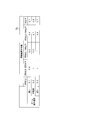
- FIG. It is an example of the table for determining the speed suppression coefficient (alpha) of focus adjustment.
- 3 is a flowchart illustrating an example of a process flow of the imaging apparatus according to the first exemplary embodiment.
- FIG. 16 is a schematic block diagram illustrating a configuration of an imaging apparatus according to Modification 9.
- FIG. 16 is a schematic block diagram illustrating a configuration of an imaging apparatus according to Modification Example 10.
- 16 is a flowchart illustrating an example of a processing flow of an imaging apparatus according to Modification Example 10.
- FIG. 16 is a schematic block diagram illustrating a configuration of an imaging apparatus according to Modification 11.
- 16 is a flowchart illustrating an example of a process flow of an imaging apparatus according to Modification 11.
- 10 is a diagram for explaining an example of a shooting scene in Embodiment 2.
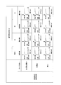
- FIG. 6 is a schematic block diagram illustrating a configuration of an imaging apparatus according to a second embodiment. It is an example of a table in which a speed adjustment coefficient ⁇ for focus adjustment is associated with each set of brightness adjustment speed and subject comparison result.
- 6 is a flowchart illustrating an example of a processing flow of an imaging apparatus according to a second exemplary embodiment.
- FIG. 10 is a diagram for describing an example of a shooting scene in a fifth modification of the second embodiment. 10 is a diagram for explaining an example of a shooting scene in Embodiment 3.
- FIG. FIG. 6 is a schematic block diagram illustrating a configuration of an imaging apparatus in Embodiment 3.
- FIG. 10 is a schematic block diagram illustrating a configuration of an imaging apparatus according to Modification 5 of Example 3.
- 16 is a flowchart illustrating an example of a process flow of an imaging apparatus according to Modification 5 of Example 3.
- FIG. 10 is a schematic block diagram illustrating a configuration of an imaging apparatus according to Modification 6 of Example 3.
- 16 is a flowchart illustrating an example of a process flow of an imaging apparatus according to Modification 6 of Example 3.
- FIG. 10 is a diagram for explaining an example of a shooting scene in the fourth embodiment.
- FIG. 10 is a schematic block diagram illustrating a configuration of an imaging device according to a fourth embodiment. It is a figure which shows the focus adjustment prohibition area
- 10 is a flowchart illustrating an example of a processing flow of an imaging apparatus in Embodiment 4. It is a conceptual diagram of the table which linked
- FIG. 16 is a schematic block diagram illustrating a configuration of an imaging apparatus according to Modification 11 of Example 4.
- 27 is a flowchart illustrating an example of a process flow of an imaging apparatus according to Modification 11 of Example 4. It is an example of a change of a prohibited area.
- FIG. 10 is a schematic block diagram illustrating a configuration of an imaging device according to a fourth embodiment. It is a figure which shows the focus adjustment prohibition area
- 10 is a flowchart illustrating an example of a processing flow
- 16 is a schematic block diagram illustrating a configuration of an imaging apparatus according to Modification 12 of Example 4.
- 16 is a flowchart illustrating an example of a process flow of an imaging apparatus according to Modification 12 of Example 4.
- FIG. 16 is a schematic block diagram illustrating a configuration of an imaging apparatus according to Modification Example 13 of Example 4.
- 28 is a flowchart illustrating an example of a process flow of an imaging apparatus according to Modification Example 13 of Example 4.
- FIG. 10 is a diagram for explaining an example of a shooting scene in the fifth embodiment.
- FIG. 10 is a schematic block diagram illustrating a configuration of an imaging apparatus in Embodiment 5. It is an example of the time characteristic from a focus adjustment start to an in-focus state.
- FIG. 10 is a flowchart illustrating an example of a processing flow of an imaging apparatus in Embodiment 5. It is an example of a person's physical focus adjustment characteristic according to the size of the subject and the moving speed of the subject.
- FIG. 10 is a schematic block diagram illustrating a configuration of an imaging apparatus according to Modification 6 of Example 2.
- FIG. 10 is a diagram for describing an example of a shooting scene in a sixth modification of the second embodiment.
- FIG. 10 is a diagram for explaining an example of an operation (setting for determining a coefficient ⁇ ) of an imaging apparatus according to Modification 6 of Example 2.
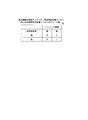
- FIG. 20 is an example of a table in which a focus adjustment start timing is associated with each set of subject saturation and panning speed in Modification 2 of Example 4.
- FIG. 16 is a schematic block diagram illustrating a configuration of an imaging device according to Modification 14 of Example 4.
- FIG. 10 is an example of temporal characteristics from a focus adjustment start to a focused state in Embodiment 5.
- FIG. It is a figure which shows the subjective evaluation result of a moving image. It is an example of the time characteristic from the focus adjustment start in a modification 5 of Example 4 to an in-focus state. It is an example of the time characteristic from the focus adjustment start in a modification 5 of Example 4 to an in-focus state. It is a figure which shows the subjective evaluation result of the moving image in the modification 5 of Example 4.
- FIG. 1 is a schematic block diagram illustrating a configuration of an imaging device according to a first embodiment of the present invention.
- FIG. 1 is a schematic block diagram illustrating a configuration of an imaging apparatus in Embodiment 1.
- FIG. 2 It is an example of the table for determining the brightness adjustment speed suppression coefficient (alpha).
- 3 is a flowchart illustrating an example of a process flow of the imaging apparatus according to the first exemplary embodiment.
- 10 is a schematic block diagram illustrating a configuration of an imaging apparatus according to Modification 9 of Example 1.
- FIG. It is an example of a table in which a shutter speed and a brightness adjustment suppression coefficient ⁇ are associated with each other.
- FIG. 16 is a flowchart illustrating an example of a process flow of the imaging apparatus according to Modification Example 9 of Example 1.
- 10 is a diagram for explaining an example of a shooting scene in Embodiment 2.
- FIG. FIG. 6 is a schematic block diagram illustrating a configuration of an imaging apparatus according to a second embodiment. It is an example of a table in which a speed suppression coefficient ⁇ is associated with each set of a focus adjustment speed and a subject comparison result.
- 6 is a flowchart illustrating an example of a processing flow of an imaging apparatus according to a second exemplary embodiment.
- 10 is a diagram for explaining an example of a shooting scene in Embodiment 3.
- FIG. FIG. 6 is a schematic block diagram illustrating a configuration of an imaging apparatus in Embodiment 3.
- FIG. 12 is a flowchart illustrating an example of a process flow of the imaging apparatus according to the third exemplary embodiment.
- FIG. 10 is a schematic block diagram illustrating a configuration of an imaging device according to Modification 4 of Example 3.
- 16 is a flowchart illustrating an example of a process flow of an imaging apparatus according to Modification 4 of Example 3.
- FIG. 10 is a diagram for explaining an example of a shooting scene in the fourth embodiment.
- FIG. 10 is a schematic block diagram illustrating a configuration of an imaging device according to a fourth embodiment. It is an example of a prohibited area.
- FIG. 16 is a schematic block diagram illustrating a configuration of an imaging apparatus according to Modification 9 of Example 4. It is an example of a change of a prohibited area. 16 is a flowchart illustrating an example of a process flow of an imaging apparatus according to Modification Example 9 of Example 4.
- FIG. 16 is a schematic block diagram illustrating a configuration of an imaging device according to Modification Example 10 of Example 4. 16 is a flowchart illustrating an example of a process flow of an imaging apparatus according to Modification Example 10 of Example 4.
- FIG. 16 is a schematic block diagram illustrating a configuration of an imaging apparatus according to Modification 11 of Example 4.
- 27 is a flowchart illustrating an example of a process flow of an imaging apparatus according to Modification 11 of Example 4.
- FIG. 10 is a diagram for explaining an example of a shooting scene in the fifth embodiment.
- FIG. 10 is a schematic block diagram illustrating a configuration of an imaging apparatus in Embodiment 5. It is an example of a table in which a brightness adjustment control coefficient ⁇ is associated with each set of zoom operation speed and luminance pixel average value.
- 10 is a flowchart illustrating an example of a processing flow of an imaging apparatus in Embodiment 5. It is an example of the table for determining the time which brightness adjustment in the modification 6 of Example 2 requires.
- FIG. 10 is a schematic block diagram illustrating a configuration of an imaging apparatus according to Modification Example 7 of Example 2. It is an example of the table for determining the correction parameter (beta) in the modification 7 of Example 2.
- FIG. FIG. 16 is a schematic block diagram illustrating a configuration of an imaging apparatus according to Modification 12 of Example 4. 16 is a flowchart illustrating an example of a process flow of an imaging apparatus according to Modification 12 of Example 4. It is an example of the time characteristic from the brightness adjustment start to the optimal brightness state.
- FIG. 16 is an example of a table in which subject saturation and brightness adjustment start timing are associated in Modification 12 of Example 4.
- FIG. It is an example of the time characteristic from the brightness adjustment start to the optimal brightness state.
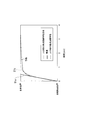
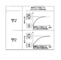
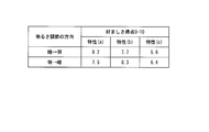
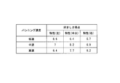
- FIG. 51 is an example of temporal characteristics from the start of focus adjustment to the focused state.
- the vertical axis represents the focal position and the horizontal axis represents time.
- the focus adjustment characteristic 51a is a focus adjustment characteristic when focus adjustment is performed at a constant speed.
- the focus adjustment characteristic 51b is a physical focus adjustment characteristic of the human eyeball.
- the focus adjustment characteristic 51c is a focus adjustment characteristic that approximates the physical focus adjustment characteristic of a human eyeball.
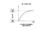
- FIG. 52 shows the result of the subjective evaluation of the viewer in 11 stages of preferred: 10 points, neither: 5 points, unfavorable: 0 points.
- the result shown in FIG. 52 is an evaluation result of a moving image in which focus adjustment is performed with behavior based on the three focus adjustment characteristics shown in FIG. 51 as an example.
- the focus adjustment to which the physical focus adjustment characteristic of the human eyeball shown in FIG. 51 is applied or the focus adjustment characteristic to which the physical focus adjustment characteristic approximating the physical focus adjustment characteristic of the human eyeball shown in FIG. 51 is applied. It was found that adjustment is preferred when watching movies, and the latter is more preferred. This is thought to be because the subjective focus adjustment that humans perceive with their instinct is not the physical focus adjustment characteristic of the eyeball but is close to the focus adjustment characteristic that approximates it. Also, in the human subjective focus adjustment, the person does not try to see all subjects in an appropriate focus state, but considers both the state of viewing and the information of the object to be viewed in his head.
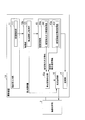
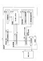
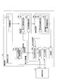
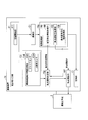
- FIG. 1 is a schematic block diagram showing the configuration of the imaging apparatus 1 according to the first embodiment of the present invention.
- the imaging apparatus 1 includes an imaging unit 12, a human subjective focus adjustment related information acquisition unit 13, and a focus adjustment determination unit 15.
- the imaging optical system 2 guides light from the subject to the imaging unit 12 and forms an image of the subject with the imaging element of the imaging unit 12.
- the imaging optical system 2 can be detached from the imaging device 1 as an example. Note that the imaging optical system 2 may be fixed to the imaging device 1.
- the imaging unit 12 captures an image of the subject formed by the imaging optical system 2 to generate a moving image signal, and outputs the generated moving image signal to the human subjective focus adjustment related information acquisition unit 13.
- the human subjective focus adjustment related information acquisition unit 13 acquires at least information related to human subjective focus adjustment from the moving image signal.
- information related to human subjective focus adjustment is determined, for example, from inter-frame change information regarding changes occurring between two or more frames, and intra-frame information that is information within one frame included in a moving image signal.
- Information relating to the situation for example, the state and movement of the imaging device
- the situation of the subject being viewed for example, the movement and color of the subject.
- the degree of attention to the subject of focus adjustment varies depending on the situation of shooting and the situation of the subject being viewed. Therefore, it can be said that these pieces of information are information related to human subjective focus adjustment.
- FIG. 57 is a schematic block diagram showing the configuration of the imaging apparatus 1 in this case.
- the human subjective focus adjustment related information acquisition unit 13 includes an interframe change information acquisition unit 13a that acquires the interframe change information and an intraframe information acquisition unit 14a that acquires information about the intraframe information. Prepare.
- the information related to the human subjective focus adjustment is not limited to the above, but is shown in the physical focus adjustment characteristics (the movement of the crystalline lens) of the human eye as shown in FIG. It may be an approximation of the physical focus adjustment characteristics of the human eyeball.
- information may be stored in advance in a memory (not shown) of the imaging apparatus 1 and information may be acquired by referring to the memory when necessary.
- the focus adjustment determination unit 15 determines the behavior of the focus adjustment using information related to human subjective focus adjustment. Thereby, it is possible to adjust the focus according to the ease of attention of the viewer and the movement of the eyeball. For this reason, the imaging apparatus 1 can provide a moving image that the photographer (or the viewer) looks more favorably, so that the satisfaction of the moving image of the photographer or the viewer can be improved.
- the focus adjustment determination unit 15 determines the behavior of the focus adjustment as follows in accordance with information related to human subjective focus adjustment. (1) The behavior of the focus adjustment is determined by determining the acceleration and the speed in the focus adjustment for bringing the subject into focus according to the information related to the subjective focus adjustment of the person.
- the behavior of the focus adjustment is determined by determining the timing for starting deceleration in the focus adjustment for bringing the subject into focus according to the information related to the subjective focus adjustment of the person.
- the behavior of the focus adjustment is determined by determining the timing for starting the focus adjustment in the focus adjustment for bringing the subject into focus in accordance with the information related to the human subjective focus adjustment.
- the behavior of the focus adjustment is determined by determining whether or not the focus adjustment can be driven according to information related to the subjective focus adjustment of the person.
- the terms “suppress focus adjustment” and “promote focus adjustment” are used, which are defined as follows. Suppress focus adjustment: Prohibit focus adjustment, or make it easy to be prohibited or slow (decrease focus adjustment speed / acceleration). Accelerate focus adjustment: perform or facilitate focus adjustment, or make it faster than when suppressing focus adjustment (to increase the speed / acceleration of focus adjustment).
- FIG. 2 is a diagram illustrating scenes assumed as shooting conditions in each embodiment.
- the subject that the photographer wants to focus on changes.
- the imaging apparatus does not vary (only subject variation).
- there is no subject change only the change of the imaging device.
- the scenes assumed in the respective embodiments are assumed.
- a scene in which a subject that was not initially imaged moves and appears in the angle of view is assumed.
- the second embodiment assumes a scene in which there are a plurality of subjects in the screen in advance, and the subject to be noticed (the subject to be focused) changes as the brightness of the subject changes.
- the third embodiment assumes a scene in which a subject moves and disappears from the screen, and another subject that has been hidden appears.
- a scene is assumed in which a subject to be imaged within an angle of view changes as the imaging apparatus physically moves.
- Example 1 Next, Example 1 will be described.
- inter-frame change information relating to changes occurring between two or more frames and intra-frame information which is information contained in one frame included in a moving image signal, are acquired as information related to human subjective focus adjustment.
- FIG. 3 is a diagram for explaining an example of a shooting scene in the first embodiment. In the figure, a scene in which a certain subject appears from the right side of the screen and moves to the center of the screen.
- the image area of the subject does not exist in the image G11 (N is a positive integer) of N + 1 frames.
- N is a positive integer
- the image area R12 of the subject is shown on the right side toward the image G12.
- the image region R13 of the subject is shown in the center of the image G13.
- FIG. 4 is a schematic block diagram illustrating the configuration of the imaging device 1a according to the first embodiment.
- the imaging apparatus 1a includes an imaging optical system 2, a photographer input unit 11, an imaging unit 12a, an image processing unit 10, a focus adjustment determination unit 15a, a focus adjustment unit 16, and a recording unit 17.
- the imaging optical system 2 guides light from the subject to the imaging unit 12a, and forms an image of the subject with an imaging element included in the imaging unit 12a.
- the image sensor generates a moving image signal of the subject.
- the imaging optical system 2 can be removed from the imaging device 1a as an example. Note that the imaging optical system 2 may be fixed to the imaging device 1a.
- the configuration of the imaging optical system 2 is the same in the following embodiments.
- the photographer input unit 11 receives a photographer's input.
- the photographer input unit 11 includes a recording start button 111 that receives a photographing start instruction from the photographer.
- the imaging unit 12a generates a moving image signal by converting light incident from the subject via the imaging optical system 2 into an electrical signal at a predetermined shutter speed.
- the imaging unit 12 a includes a focus adjustment amount acquisition unit 121.
- the image processing unit 10 generates image data from the moving image signal supplied from the imaging unit 12a, and causes the recording unit 17 to record the generated image data.
- the image processing unit 10 includes an inter-frame change information acquisition unit 13a and an in-frame information acquisition unit 14a.
- the inter-frame change information acquisition unit 13a includes a subject motion information acquisition unit 131
- the intra-frame information acquisition unit 14a includes a subject size information acquisition unit 141.
- the imaging apparatus 1a sets an area for focus adjustment in advance.
- the imaging device 1a performs face detection to extract a detected face that is an image area of the face, and the extracted detected face is set as an area for focus adjustment.
- the imaging apparatus 1a holds a facial feature database in which images of characteristic parts (for example, eyes and mouth) in the face are stored.
- the image processing unit 10 extracts an image region in an image obtained by imaging, and compares the extracted image region with an image stored in the facial feature database, thereby obtaining the face of the subject. Detect the image area.
- the focus adjustment unit 16 can perform focus adjustment on the detected face by using the detected image area of the face of the subject as the detected face.
- the recording start button 111 receives a moving image recording start instruction from the photographer, and outputs start instruction information indicating the received start instruction to the imaging unit 12a.
- the imaging unit 12a receives the start instruction information from the photographer input unit 11, the imaging unit 12a converts the light incident from the subject via the imaging optical system 2 into an electrical signal at a predetermined shutter speed, thereby converting the moving image signal. Generate. Thereby, the imaging unit 12a can start moving image recording in accordance with a photographer's instruction.
- the imaging unit 12a outputs the generated moving image signal to the image processing unit 10.
- the imaging unit 12a includes, for example, an imaging element that is used as a phase difference element in which a part of a plurality of light receiving elements arranged on the image plane detects a phase difference.
- the imaging unit 12a splits the light incident from the subject into a plurality of light beams, and causes the split light beams to enter different phase difference elements. Thereby, the phase difference element converts the incident light into an electric signal.
- the focus adjustment amount acquisition unit 121 acquires a focus adjustment amount for bringing the focus adjustment target area into a focused state based on the information on the set focus adjustment area, and uses the acquired focus adjustment amount as the focus adjustment unit. 16 is output.
- the focus adjustment amount is acquired from a phase difference element arranged on the image plane of the imaging element of the imaging unit.
- the focus adjustment amount acquisition unit 121 acquires the focus adjustment amount by observing the phase difference between the electrical signals obtained by conversion by different phase difference elements.
- the focus adjustment amount acquisition unit 121 outputs the acquired focus adjustment amount to the focus adjustment unit 16.
- the moving speed is, for example, the face center speed (pixel / Frame).
- the subject motion information acquisition unit 131 may detect the center position of the detected face in one frame and the center position of the detected face in the next frame, and calculate the number of moving pixels of the center position of the detected face as the center speed of the face. Good.
- the subject motion information acquisition unit 131 is not limited to this, the distance from the imaging device to the subject (this distance is detected from the phase difference element as an example), the angle of view, and the lateral direction of the imaging element.
- the horizontal width of the imaging range in real space may be calculated from the length.
- the subject motion information acquisition unit 131 sets the moving pixel count (pixel) at the center position of the detected face to the horizontal width of the imaging range in the calculated real space by the horizontal pixel count (eg, 1024) of the captured image. By multiplying by the divided number, the number of moving pixels at the center position of the detected face may be converted into the center speed (m / Frame) of the face in real space.
- the subject movement speed as well as the subject size is compared with an arbitrary threshold value stored in advance in a memory (not shown) in the image pickup apparatus 1a, so that it is "substantially faster” Although it is determined as one of “fast”, “medium”, and “slow”, the acquired movement speed (for example, pixel / frame) of the subject may be used as it is.
- the subject motion information acquisition unit 131 outputs subject motion speed information indicating the motion speed of the subject to the focus adjustment determination unit 15a.
- the subject size information acquisition unit 141 acquires subject size information indicating the size of the subject as in-frame information, and outputs the acquired subject size information to the focus adjustment determination unit 15a.
- An example of the specific processing will be described.
- a first threshold value for separating “extra large (extra extent from the screen)” and “large”, “large” and “large” A second threshold value for separating “medium” and a third threshold value for separating “medium” and “small” are stored in advance.
- “extra large”, “large”, “medium”, and “small” are classifications of the size of the subject.
- the subject size information acquisition unit 141 acquires, for example, the size of the detected face as the size of the subject, and the acquired subject size and the first threshold value and the second threshold value stored in a memory (not shown). , And the third threshold value, the subject size is determined to be “extra large”, “large”, “medium”, or “small”.
- the present invention is not limited to this, and for example, information on the number of pixels of the detected face may be used as it is.
- the size of the subject is not limited to the size of the detected face, and the subject size information acquisition unit 141 determines the background region and the non-subject subject region by a known technique such as figure-ground determination, and performs focus adjustment.
- the size of the subject area in the vicinity may be the size of the subject.
- the vicinity of the area where the focus adjustment is performed includes, for example, an area where the focus adjustment is performed, and also includes pixels which are separated from the area by a predetermined number of pixels.
- the subject size information acquisition unit 141 uses the color of each image area or the distance of the image area from the imaging device (this distance is detected from the phase difference element as an example), Of the image areas determined and determined as “figure”, the size of the image area closest to the above-described focus adjustment area (here, as an example, the detected face) may be the size of the subject.
- the subject can be arbitrarily selected.
- the photographer input unit 11 accepts an input of the subject selection by the photographer, and the subject size information acquisition unit 141 receives the input accepted by the photographer input unit 11.
- Subject size information may be acquired for the subject shown.
- the subject size information acquisition unit 141 acquires the subject size in the frame as subject size information as an example.
- the subject size information is obtained by the following processing. May be acquired and used as subject size information.
- (1) Object physical size information acquisition process 1 As an example, the subject size information acquisition unit 141 may perform triangulation using the previous frame information to obtain the physical subject size.
- (2) Acquisition process 2 of physical size information of the subject The imaging apparatus 1a stores an average size of a general subject in a memory (not shown) in advance.
- the imaging device 1a may perform object recognition processing of a subject to be imaged using a known technique and specify what the subject to be imaged is. Then, as an example, the subject size information acquisition unit 141 may obtain the average size information of the subject stored in advance as the physical size of the subject.
- the focus adjustment determination unit 15 a determines the behavior of brightness adjustment from the subject size information acquired by the subject size information acquisition unit 141 and the subject movement speed information acquired by the subject motion information acquisition unit 131.
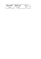
- a memory (not shown) in the imaging apparatus 1a stores a table as shown in FIG. 5 in which one brightness adjustment speed suppression coefficient ⁇ is associated with a set of a subject size and a subject movement speed. Has been.
- the focus adjustment determination unit 15a reads the focus adjustment speed suppression coefficient ⁇ corresponding to the set of the acquired subject size information and the acquired subject movement speed information with reference to the table of FIG.
- a reference focus adjustment speed V base at the time of moving image shooting is stored in advance in a memory (not shown).
- the focus adjustment determination unit 15a reads the reference focus adjustment speed V base from the memory, and determines the actual focus adjustment speed V control according to the following equation (1).
- V control V base ⁇ ⁇ (1)
- the focus adjustment determination unit 15a changes the speed of focus adjustment. For example, the focus adjustment is performed by selecting either “to operate” or “forbid” the focus adjustment. It may be suppressed.
- the focus adjustment determination unit 15 a outputs the determined focus adjustment behavior to the focus adjustment unit 16.
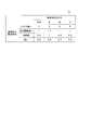
- FIG. 5 is an example of a table for determining the focus adjustment speed suppression coefficient ⁇ .
- the focus adjustment speed suppression coefficient ⁇ is associated with each set of the movement speed of the subject and the size of the subject.
- the focus adjustment speed suppression coefficient ⁇ tends to be small, and is slower than that (“somewhat fast”, “medium”, “slow” in FIG. 5). In the case), the slower the movement speed of the subject, the smaller the focus adjustment speed suppression coefficient ⁇ .
- the moving speed of the subject is higher than a certain level, the focus adjustment is suppressed, and when the speed is lower than a certain level, the slower the speed, the more the focus adjustment is suppressed.
- a video can be provided.
- the focus adjustment speed suppression coefficient ⁇ tends to increase when the subject size is “large” and “medium”, and tends to decrease in the order of “small” and “extra large”. Is done.
- the imaging apparatus 1a can be controlled by the photographer (or the viewer) by suppressing the focus adjustment. It is possible to provide a video that looks more like.
- the focus adjustment unit 16 controls the focus adjustment optical system of the imaging optical system 2 based on the focus adjustment behavior (focus adjustment speed) determined by the focus adjustment determination unit 15a to adjust the focus.
- the focus adjustment optical system of the imaging optical system 2 is controlled to perform focus adjustment.
- the present invention is not limited to this process.
- the reference “Light Field Photography with a Hand-Held Plenoptic Camera” Ren Ng et al. Stanford Tech Report CTSR 2005-02 ” is used to shoot using an imaging optical system, etc., and after image processing, an image focused on the area to be focused is generated by image processing. good.
- the imaging optical system having the structure shown in the above-mentioned reference is an imaging optical system having the structure of a light field camera.
- a microlens array is attached between the main lens of the imaging apparatus and the imaging element, and the imaging optical system can be viewed from many directions. It is an optical system that simultaneously records the light beams. As a result, the focal point can be freely changed from the background to the front after shooting.
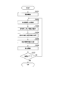
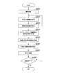
- FIG. 6 is a flowchart illustrating an example of a processing flow of the imaging apparatus 1a according to the first embodiment.
- Step S101 First, when the recording start button 111 is pressed, the imaging unit 12a starts shooting.
- Step S102 Next, the focus adjustment amount acquisition unit 121 acquires a focus adjustment amount.
- Step S103 Next, the subject size information acquisition unit 141 acquires subject size information.
- Step S104 Next, the subject motion information acquisition unit 131 acquires subject motion speed information as an example of subject motion information.
- Step S105 the focus adjustment determination unit 15a determines the behavior of the focus adjustment using the subject movement speed information and the subject size information.
- Step S106 the focus adjusting unit 16 adjusts the focus according to the determined behavior of the focus adjustment.
- the imaging unit 12 a determines whether or not the shooting has ended based on information received by the photographer input unit 11. If the shooting has not ended (NO), the process returns to step S102. In the case of the end of shooting (YES), the imaging device 1a ends the process. Above, the process of this flowchart is complete
- the focus adjustment determination unit 15a determines the behavior of the focus adjustment using, for example, the subject movement speed information and the subject size information. For example, in a scene where a subject (a person in the example of FIG. 3) appears from the right side of the image capturing apparatus 1a without movement and change, and the moving speed of the moving subject is too fast in a scene where focus adjustment is performed, Since the viewer (viewer) does not tend to determine that the subject is in focus, the focus adjustment determination unit 15a determines the focus adjustment behavior so as to suppress the focus adjustment. However, once it is determined that focus adjustment is to be performed (when the movement speed of the subject is below a certain level), the slower the movement speed of the subject, the more gradual focus adjustment tends to be preferred.
- the determination unit 15a determines the focus adjustment behavior so as to suppress the focus adjustment as the moving speed is slower.
- the sixth threshold value in which the size of the moving subject is determined in advance. If it is smaller or larger than the seventh threshold value, the focus adjustment determination unit 15a determines the focus adjustment behavior to suppress the focus adjustment.
- the seventh threshold is larger than the sixth threshold.
- the subject motion information acquisition unit 131 acquires subject motion speed information as subject motion information.
- the subject motion amount and the like are also included. May be obtained, and the behavior of the focus adjustment may be determined ⁇ Modification 1: Subject movement amount>
- the subject motion information acquisition unit 131 in FIG. 4 may acquire “subject motion amount” instead of “subject motion speed”.
- the subject motion information acquisition unit 131 may acquire the amount of motion of the subject by image processing as well as the motion speed of the subject.
- the amount of movement referred to here may be the amount of movement after an arbitrary subject starts moving, or may be the amount of movement between an arbitrary number of frames.
- the subject movement information acquisition unit 131 acquires the amount of movement from a frame that appears at the angle of view as an example.
- the larger the amount of movement from when the subject appears at the angle of view the more the subject moves after a certain distance within the angle of view
- the photographer (or viewer) focuses on the moving subject. It is easy to judge that you want to be in a state. Accordingly, the focus adjustment determination unit 15a may determine the behavior of the focus adjustment so as to suppress the focus adjustment operation as the subject movement amount is smaller.
- the subject movement information acquisition unit 131 in FIG. 4 may acquire “differences in movement states of a plurality of subjects” instead of “subject movement speed”.
- the subject movement information acquisition unit 131 acquires the difference information (for example, the difference in the moving direction) of the movement states of a plurality of subjects, for example, by image processing using the following processing method, as with the speed of the subject.
- the subject motion information acquisition unit 131 detects the face of the subject, and acquires motion information for all detected faces when a plurality of faces are detected.
- the subject movement information acquisition unit 131 acquires the difference information (here, the difference in the movement direction) of the plurality of subjects, and the focus adjustment determination unit 15a includes the difference in the movement state of the plurality of subjects (here, the movement direction). It is preferable to determine the behavior of the focus adjustment so as to suppress the focus adjustment operation so that there is no difference.
- the difference information of the movement direction is acquired as the difference information of the movement states of the plurality of subjects, but the subject movement information acquisition unit 131 may acquire the difference information of the movement speed, the difference of the movement amount, and the like.
- the focus adjustment determination unit 15a may determine the behavior of the focus adjustment using the difference information of the movement speed or the difference of the movement amount. For example, the focus adjustment determination unit 15a may promote focus adjustment when a difference in moving speed of a certain subject exceeds a predetermined reference as compared to other subjects. As a result, when there is a large difference in moving speed between one subject and another, the viewer will pay attention to the subject and want to see the subject quickly and clearly. Satisfaction can be improved.
- the focus adjustment determination unit 15a may suppress focus adjustment.
- the imaging apparatus 1a Can provide a moving image that looks better for the photographer (or viewer).
- the subject motion information acquisition unit 131 in FIG. 4 may acquire “subject motion type information” instead of “subject motion speed”.
- the movement type information of the subject is, for example, information regarding the movement when “walking” or information regarding the movement when “running” when the subject is a human being.
- the subject motion information acquisition unit 131 acquires subject motion type information, similar to the subject speed, by image processing using, for example, the following processing method.
- Step 1 Information about a motion pattern on a face area image when a human is walking and information about a motion pattern on a face area image when a human is running are captured as reference information. Stored in advance in the memory of the device 1a.
- Procedure 2 When the photographer starts photographing, the imaging unit 12a generates a moving image signal of the subject as described above.
- Procedure 3 The subject motion information acquisition unit 131 detects a face area by performing face recognition processing on the moving image signal generated by the imaging unit 12a.
- Procedure 4 The subject motion information acquisition unit 131 tracks the detected face area to acquire information on the motion of the face area on the image.
- Procedure 5 Humans in a plurality of movement patterns (movement patterns when walking, movement patterns while running, etc.) that the subject movement information acquisition unit 131 stores as reference information in the memory in the above-described procedure 1
- the information on the movement of the face area on the image is collated with the information on the movement of the face area detected in the above-described procedure 4, so that the plurality of motion patterns stored in the procedure 1 are acquired in the procedure 4.
- the movement of the pattern that most closely approximates the movement is identified as information relating to the current movement of the subject (movement of the human face). For example, if the movement acquired in step 4 is the closest to the movement pattern of the face area when a person is running among the movement patterns stored in step 1, the subject movement information acquisition unit 131 may It is determined that the movement is a movement when a human is running.
- the procedure for determining the movement when the subject is “walking” and the movement when the subject is “running” by image processing is not limited to the above steps 1 to 5. . Since people tend to want to focus faster when the subject is running than when they are walking, it is better to determine the focus adjustment behavior to facilitate focus adjustment.
- the subject movement information acquisition unit 131 in FIG. 4 may acquire “subject movement direction” instead of “subject movement speed”.
- the subject motion information acquisition unit 131 acquires subject motion type information as well as the subject speed by image processing. As a human sense, there is a tendency to focus faster when the subject moves in a horizontal and vertical direction than a subject that moves in an oblique direction, so focus adjustment is promoted when the subject moves in a horizontal direction. It is better to determine the behavior of the focus adjustment.
- subject movement information is acquired as subject change information, but the following information may be acquired to determine the focus adjustment behavior.
- the subject movement information acquisition unit 131 in FIG. 4 may be replaced with a subject deformation information acquisition unit, and the subject deformation information acquisition unit may acquire “subject color change information” instead of “subject movement speed”.
- the subject color change information is information indicating the subject color change. For example, when the subject changes color (such as changing the background on the stage or changing the subject), the ease of drawing attention to the subject changes depending on the amount or speed of change in color.
- the processing method and effect for determining the behavior of the focus adjustment are the same as in the case of acquiring subject movement information. Accordingly, the subject deformation information acquisition unit may acquire the subject color change information, and the focus adjustment determination unit 15a may determine the behavior of the focus adjustment.
- the focus adjustment determining unit 15a decreases as the color change amount or the color change speed of a certain subject decreases. Focus adjustment may be suppressed. Further, when the color change amount or the color change speed of a certain subject is equal to or less than a predetermined reference, the viewer does not pay attention to the subject, so the focus adjustment determination unit 15a may suppress the focus adjustment.
- the subject movement information acquisition unit 131 in FIG. 4 may replace the “subject deformation information acquisition unit”, and the subject deformation information acquisition unit may acquire “subject deformation information” instead of “subject movement speed”.
- the ease of drawing attention to the subject varies depending on the deformation speed or amount of deformation of the subject when the subject is deformed (such as a balloon is inflated).
- the process and effect for determining the behavior of the focus adjustment are the same as in the case of acquiring subject movement information. Therefore, the subject deformation information acquisition unit may acquire the subject deformation information, and the focus adjustment determination unit 15a may determine the behavior of the focus adjustment.
- the focus adjustment determination unit 15a may suppress the focus adjustment.
- Inter-frame signal value change amount of moving image signal to be captured The subject motion information acquisition unit 131 in FIG. 4 is changed to an inter-frame signal change amount acquisition unit of a moving image signal to be captured, and the inter-frame signal change amount acquisition unit of the captured video signal is not a motion speed of the subject.
- the inter-frame signal value change amount of the moving image signal to be captured may be acquired.
- the focus adjustment determination unit 15a may calculate the difference between the corresponding pixel values for all the pixels, and acquire the sum of the absolute values of the calculated differences as the inter-frame signal value change amount.
- An inter-frame signal value change amount (a change rate or the like can be obtained therefrom) in the captured moving image signal may be acquired.
- the process and effect for determining the behavior of the focus adjustment are the same as in the case of acquiring subject movement information.
- the case where the inter-frame signal value change amount is large is a case where panning or a large amount of change occurs in the screen. If the focus adjustment is further performed in this state, the appearance of the moving image is deteriorated. Therefore, the viewer does not like that the focus adjustment is performed in this state. Therefore, for example, the focus adjustment determination unit 15a may suppress the focus adjustment as the inter-frame signal value change amount is larger. Further, the focus adjustment determination unit 15a may suppress focus adjustment when the amount of change in the inter-frame signal value exceeds a predetermined reference.
- ⁇ Modification 8 Tracking information of an arbitrary point or area of a frame image>
- the subject movement information acquisition unit 131 in FIG. 4 may be replaced with a tracking information acquisition unit, and the tracking information acquisition unit may acquire tracking information of an arbitrary point or region of the frame image instead of “subject movement speed”.
- the frame image is an image obtained for each frame from the moving image signal.
- the tracking information acquisition unit may acquire tracking information of an arbitrary characteristic point (corner, edge, etc.) or an arbitrary area in an image that is not limited to a face obtained by a known technique.
- the process and effect for determining the behavior of the focus adjustment are the same as in the case of acquiring subject movement information.
- the tracking information is, for example, a change amount in the feature amount space by a known tracking technique.
- the focus adjustment determination unit 15a suppresses the focus adjustment. Also good. As a result of tracking, if the tracking target moves too fast or does not move very much, the viewer does not pay attention to the tracking target. Therefore, for example, when the movement speed of the tracking target exceeds a predetermined first threshold or when the movement amount (or movement speed) of the tracking target is equal to or less than a predetermined second threshold, the focus adjustment determination unit 15a Adjustment may be suppressed.
- the second threshold value is smaller than the first threshold value.
- the focus adjustment determination unit 15a may suppress the focus adjustment as the movement amount of the tracking target or the tracking target is smaller.
- the focus adjustment behavior is determined using information related to inter-frame change and information within one frame as information related to human subjective focus adjustment.
- the behavior of the focus adjustment may be corrected using “information relating to setting for photographing” or “information relating to which phase difference element is used” (specific examples are shown below). These pieces of information cannot be said to be information related to human subjective focus adjustment, but are factors that affect preferred focus adjustment when watching moving images. It is possible to determine a more preferable focus adjustment behavior by additionally acquiring these pieces of information and correcting the determined focus adjustment behavior using the acquired information.
- the information regarding which phase difference element is used is obtained by using which phase difference element to perform the focus adjustment using the phase difference signal as in this embodiment. It can be acquired when it is possible to vary the operation.
- the focus adjustment determination unit 15a temporarily determines the behavior of the focus adjustment using the subject movement information acquired as information related to the change between frames and the subject size information acquired as information within one frame.
- the behavior of the focus adjustment may be determined by correcting the temporarily determined behavior of the focus adjustment using the third information.
- FIG. 7 is a schematic block diagram illustrating a configuration of the imaging device 1b according to Modification 9.
- symbol is attached
- the imaging setting information acquisition unit 18 is added to the configuration of the imaging apparatus 1a in the first embodiment in FIG. 4, and the focus adjustment determination unit 15a is changed to the focus adjustment determination unit 15b. It has been done.
- the shooting setting information acquisition unit 18 acquires shooting setting information, which is information related to shooting settings, and outputs the acquired information related to shooting settings to the focus adjustment determination unit 15b.
- the shooting setting information acquisition unit 18 acquires ISO sensitivity setting information of the imaging apparatus 1b as shooting setting information.
- the ISO sensitivity of the imaging device 1b is high, noise in the screen increases and the appearance of the moving image becomes troublesome. In such a state, since further changes in the moving image are easily disliked, it is better to suppress the focus adjustment when the sensitivity is high.
- a table in which the ISO sensitivity and the focus adjustment suppression coefficient ⁇ are associated with each other is stored in advance in a memory (not shown).
- the higher the ISO sensitivity the smaller the focus adjustment suppression coefficient ⁇ .
- the focus adjustment determination unit 15b refers to a memory table (not shown) and reads the focus adjustment suppression coefficient ⁇ corresponding to the ISO sensitivity of the imaging device 1a to obtain the focus adjustment suppression coefficient ⁇ . decide. Then, the focus adjustment determination unit 15b determines the final focus adjustment behavior, for example, according to the following equation (2).
- V control V base ⁇ ⁇ ⁇ ⁇ (2)
- Equation (2) is an equation that corrects the behavior of the focus adjustment determined by Equation (1) described above.
- the focus adjustment determination unit 15b corrects the behavior of the focus adjustment so that the focus adjustment is suppressed as the focus adjustment suppression coefficient ⁇ is smaller. That is, as the ISO sensitivity is higher, the focus adjustment determination unit 15b decreases the focus adjustment suppression coefficient ⁇ in Expression (2) and corrects the behavior of the focus adjustment so that the focus adjustment is suppressed.
- the shooting setting information acquisition unit 18 acquires shutter speed setting information of the imaging device 1b as shooting setting information. If the shutter speed setting of the imaging device 1b is faster than the frame rate at the time of moving image capturing, the motion of the moving image is not smooth (the moving image looks like a flip book). Therefore, for example, the focus adjustment determination unit 15b corrects the behavior of the focus adjustment so as to suppress the focus adjustment as the shutter speed setting of the imaging device 1b is faster than the frame rate at the time of moving image capturing.
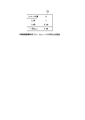
- FIG. 8 is an example of a table T2 in which the shutter speed and the focus adjustment suppression coefficient ⁇ stored in a memory (not shown) are associated with each other.
- the focus adjustment suppression coefficient ⁇ decreases as the shutter speed increases.
- the focus adjustment determination unit 15b refers to a table T2 (see FIG. 8) stored in a memory (not shown), and reads the focus adjustment suppression coefficient ⁇ corresponding to the shutter speed setting.
- the focus adjustment suppression coefficient ⁇ is determined.
- the focus adjustment determination unit 15b corrects the behavior of the focus adjustment according to Expression (2), as in Example 1. Thereby, the focus adjustment determination unit 15b corrects the behavior of the focus adjustment so as to suppress the focus adjustment because the focus adjustment suppression coefficient ⁇ in the equation (2) becomes smaller as the shutter speed setting is faster.
- the shooting setting information acquisition unit 18 acquires F value setting information of the imaging optical system 2 attached to the imaging device 1b as shooting setting information. If the F-number setting of the imaging optical system 2 attached to the imaging device 1b is small, the depth of field becomes shallow. When the depth of field is shallow, it is easy to focus on one subject. Therefore, for example, the focus adjustment determination unit 15b corrects the behavior of the focus adjustment so as to suppress the focus adjustment as the F value setting of the imaging device 1b is larger.
- a table in which the F value and the focus adjustment suppression coefficient ⁇ are associated with each other is stored in advance in a memory (not shown).
- the focus adjustment suppression coefficient ⁇ decreases as the F value increases.
- the focus adjustment determination unit 15b refers to a memory table (not shown) and reads the focus adjustment suppression coefficient ⁇ corresponding to the F value to determine the focus adjustment suppression coefficient ⁇ .
- the focus adjustment determination unit 15b corrects the behavior of the focus adjustment according to Expression (2), as in Example 1. Thereby, the focus adjustment determination unit 15b corrects the behavior of the focus adjustment so as to suppress the focus adjustment because the focus adjustment suppression coefficient ⁇ in the equation (2) decreases as the F value increases.
- the shooting setting information acquisition unit 18 acquires the focal length setting information of the imaging optical system 2 attached to the imaging device 1b as shooting setting information.
- the focus adjustment determination unit 15b determines the behavior of the focus adjustment so that the focus adjustment is suppressed as the focal length setting of the imaging optical system 2 attached to the imaging device 1b is shorter.
- a table in which a focal length and a focus adjustment suppression coefficient ⁇ are associated with each other is stored in advance in a memory (not shown).
- the focus adjustment determination unit 15b refers to a memory table (not shown) and reads the focus adjustment suppression coefficient ⁇ corresponding to the focal length to determine the focus adjustment suppression coefficient ⁇ .
- the focus adjustment determination unit 15b corrects the behavior of the focus adjustment according to Expression (2), as in Example 1. Thereby, the focus adjustment determination unit 15b corrects the behavior of the focus adjustment so as to suppress the focus adjustment because the focus adjustment suppression coefficient ⁇ in the equation (2) becomes smaller as the focal length is shorter.
- the shooting setting information acquisition unit 18 acquires setting information of image processing of the imaging device 1b as shooting setting information.
- NR noise reduction
- a table in which the NR intensity and the focus adjustment suppression coefficient ⁇ are associated with each other is stored in advance in a memory (not shown).
- the focus adjustment suppression coefficient ⁇ decreases as the NR intensity decreases.
- the focus adjustment determination unit 15b refers to a memory table (not shown) and reads the focus adjustment suppression coefficient ⁇ corresponding to the NR intensity to determine the focus adjustment suppression coefficient ⁇ .
- the focus adjustment determination unit 15b corrects the behavior of the focus adjustment according to Expression (2), as in Example 1. Thereby, the focus adjustment determination unit 15b decreases the focus adjustment suppression coefficient ⁇ in the equation (2) as the NR intensity is lower, and thus corrects the behavior of the focus adjustment so as to suppress the focus adjustment.
- the shooting setting information acquisition unit 18 acquires the presence / absence or intensity of an expression enhancement process as setting information for image processing of the imaging apparatus 1b, which is an example of shooting setting information.
- the expression enhancement processing is, for example, processing for enhancing the saturation of the entire image and enhancing the captured image colorfully and impressively. The more the expression enhancement processing is applied, the stronger the irritation to the eyes in the screen, so it is better to suppress the focus adjustment. Accordingly, the focus adjustment determination unit 15b determines the behavior of the focus adjustment so as to suppress the focus adjustment, for example, as the degree to which the expression enhancement process is applied is larger.
- the focus adjustment determination unit 15b determines the behavior of the focus adjustment so as to suppress the focus adjustment, for example, as the intensity of the expression enhancement process is higher. For example, the focus adjustment determination unit 15b determines the behavior of the focus adjustment so as to further suppress the focus adjustment in which the expression emphasis process is not performed.
- a table in which the strength of the expression enhancement process and the focus adjustment suppression coefficient ⁇ are associated with each other is stored in advance in a memory (not illustrated).
- the focus adjustment suppression coefficient ⁇ decreases as the strength of the expression enhancement process increases.
- the intensity of the expression enhancement process is 0.
- the focus adjustment determination unit 15b refers to a memory table (not shown) and reads the focus adjustment suppression coefficient ⁇ corresponding to the intensity of the expression emphasis process to thereby adjust the focus adjustment suppression coefficient ⁇ . To decide.
- the focus adjustment determination unit 15b corrects the behavior of the focus adjustment according to Expression (2), as in Example 1. Accordingly, the focus adjustment determination unit 15b corrects the behavior of the focus adjustment so as to suppress the focus adjustment because the focus adjustment suppression coefficient ⁇ in the expression (2) becomes smaller as the strength of the expression enhancement process is higher.
- FIG. 9 is a flowchart illustrating an example of a processing flow of the imaging apparatus according to Modification 9.
- Step S201 First, when the recording start button 111 is pressed, the imaging unit 12a starts shooting.
- Step S202 Next, the focus adjustment amount acquisition unit 121 acquires a focus adjustment amount.
- Step S203 Next, the subject size information acquisition unit 141 acquires subject size information.
- Step S204 Next, the subject motion information acquisition unit 131 acquires subject motion speed information as an example of subject motion information.
- the shooting setting information acquisition unit 18 acquires shooting setting information.
- the focus adjustment determination unit 15b determines the behavior of the focus adjustment using the subject movement speed information, the subject size information, and the shooting setting information.
- Step S207 Next, the focus adjustment unit 16 adjusts the focus according to the determined focus adjustment behavior.
- Step S208 Next, the imaging unit 12a determines whether or not the photographing is finished. If the shooting has not ended (NO), the process returns to step S202. In the case of shooting end (YES), the imaging device 1b ends the process. Above, the process of this flowchart is complete
- the focus adjustment determination unit 15b determines the focus adjustment behavior using, for example, the shooting setting information in addition to the subject movement information and the subject size information. At that time, for example, the imaging apparatus 1b determines the behavior of the focus adjustment so as to suppress the focus adjustment as the phase difference elements are used at sparse intervals. Thereby, since the imaging device 1b can correct the focus adjustment behavior with the shooting setting information, it is possible to perform the focus adjustment according to the ease of the viewer's attention. Therefore, the imaging device 1b can provide a moving image that looks better for the photographer (or the viewer).
- FIG. 10 is a schematic block diagram illustrating a configuration of the imaging device 1c according to Modification Example 10.
- symbol is attached
- the configuration of the imaging apparatus 1c in the modification 10 is the same as that of the imaging apparatus 1a in the first embodiment shown in FIG. 4 except that a phase difference use state acquisition unit 19 is added and the photographer input unit 11 is added to the photographer input unit 11b. It has been changed.
- the photographer input unit 11b has a use phase difference pixel input unit 112 added to the photographer input unit 11 of the first embodiment shown in FIG.
- Modification 10 it is assumed that when the focus adjustment amount is acquired using the phase difference signal, it is possible to vary which phase difference element is used to acquire the focus adjustment amount.
- the user inputs a used phase difference pixel that is a pixel of the phase difference element to be used.
- the used phase difference pixel input unit 112 receives an input of the used phase difference pixel by the user, and outputs the received input information to the phase difference use state acquisition unit 19 and the focus adjustment amount acquisition unit 121.
- the phase difference usage status acquisition unit 19 acquires phase difference element usage status information regarding which phase difference element is used from the input information input from the usage phase difference pixel input unit 112.
- the phase difference element usage status information indicates, for example, whether the phase difference element is used at a sparse interval (reading speed priority) or at a dense interval (followability priority).
- the focus adjustment amount acquisition unit 121 determines a phase difference element used to calculate the focus adjustment amount from the input information input from the used phase difference pixel input unit 112, and uses the phase difference element to adjust the focus adjustment amount. To get.
- the focus adjustment determination unit 15c acquires, for example, phase difference element usage status information, and determines the behavior of focus adjustment so that the focus adjustment is suppressed as the phase difference elements with sparse intervals are used. To do.
- a table in which a phase difference element usage state and a focus adjustment suppression coefficient ⁇ are associated with each other is stored in advance in a memory (not illustrated).
- the focus adjustment suppression coefficient ⁇ becomes smaller as the phase difference elements with sparse intervals are used.
- the focus adjustment determination unit 15c refers to a memory table (not shown) and reads the focus adjustment suppression coefficient ⁇ corresponding to the use state of the phase difference element. To decide.
- the focus adjustment determination unit 15c corrects the behavior of the focus adjustment according to Expression (2), as in Example 1.
- the focus adjustment determination unit 15c suppresses the focus adjustment because the focus adjustment suppression coefficient ⁇ in the equation (2) becomes smaller as the phase difference elements with sparse intervals are used. Correct the focusing behavior.
- FIG. 11 is a flowchart illustrating an example of a processing flow of the imaging device 1c according to the tenth modification.
- Step S301 First, when the recording start button 111 is pressed, the imaging unit 12a starts shooting.
- Step S302 Next, the used phase difference pixel input unit 112 receives an input of the used phase difference pixel by the user.
- Step S303 Next, the focus adjustment amount acquisition unit 121 acquires a focus adjustment amount.
- the subject size information acquisition unit 141 acquires subject size information.
- the subject motion information acquisition unit 131 acquires subject motion speed information as an example of subject motion information.
- Step S306 the phase difference usage status acquisition unit 19 acquires the phase difference element usage status based on the input received by the usage phase difference pixel input unit 112.
- Step S307 the focus adjustment determination unit 15c determines the focus adjustment behavior using the subject movement information, the subject size information, and the phase difference element usage state.
- Step S308 the focus adjustment unit 16 adjusts the focus according to the determined focus adjustment behavior.
- Step S309 the imaging unit 12a determines whether or not the photographing is finished. If the shooting has not ended (NO), the process returns to step S303. In the case of the end of shooting (YES), the imaging device 1c ends the process. Above, the process of this flowchart is complete
- the focus adjustment determination unit 15c determines the focus adjustment behavior using the phase difference element usage state in addition to the subject movement information and the subject size information. At this time, for example, the imaging apparatus 1c determines the behavior of the focus adjustment so as to suppress the focus adjustment as the phase difference elements at sparse intervals are used. Thereby, even if it is difficult to follow the smooth focus adjustment when the phase difference element is sparse, the imaging device 1c can suppress the change in the amount of blur more than necessary by suppressing the focus adjustment operation. . Therefore, the imaging device 1c can provide a moving image that looks better for the photographer (or the viewer).
- FIG. 12 is a schematic block diagram illustrating the configuration of the imaging device 1d according to the eleventh modification.
- symbol is attached
- the use phase difference pixel determination unit 20 is added to the configuration of the imaging device 1c in the modification 10 in FIG.
- the acquisition unit 19d is changed.
- the used phase difference pixel determination unit 20 includes a gyro sensor 201.
- the processing of the focus adjustment determination unit 15c is the same as that of the focus adjustment determination unit 15c of the example 10 in FIG.
- the gyro sensor 201 is a triaxial gyro sensor, for example, and detects an angular velocity around each axis.
- the used phase difference pixel determination unit 20 determines how the imaging device 1d is moving based on the angular velocity around each axis detected by the gyro sensor 201, and based on the determined result, the focus adjustment amount The used phase difference pixel to be used when calculating the is determined.
- the use phase difference pixel determination unit 20 outputs the determined use phase difference pixel to the phase difference use state acquisition unit 19d and the focus adjustment amount acquisition unit 121.
- the use phase difference pixel determination unit 20 determines that the imaging device 1d is panning, the phase difference elements in the vertical direction do not have to be so dense. It is better to set so that readout of pixels in which elements are arranged is thinned out in the vertical direction. Therefore, for example, when the use phase difference pixel determination unit 20 determines that the imaging apparatus 1d is panning, the use phase difference pixel is set to a pixel in which the phase difference elements in a certain row (for example, the center row) are arranged. decide.
- the use phase difference pixel determination unit 20 determines that the imaging device 1d is moving fast, it is better to increase the speed of focus adjustment (focus adjustment). Since it is better to place importance on responsiveness), it may be set to thin out the readout of the pixels where the phase difference elements are arranged to a predetermined extent. Thus, by adjusting the focus quickly according to the fast movement of the imaging apparatus, even if the subject changes one after another, the changed subject can be focused immediately.
- the phase difference usage status acquisition unit 19d acquires phase difference element usage status information regarding which phase difference element is used based on the usage phase difference pixels input from the usage phase difference pixel determination unit 20.
- the phase difference element usage status information indicates, for example, whether the phase difference elements are used at sparse intervals (priority in reading speed) or are used at close intervals (follow-up priority).
- the focus adjustment amount acquisition unit 121 acquires the focus adjustment amount using the phase difference element of the used phase difference pixel input from the used phase difference pixel determination unit 20.
- FIG. 13 is a flowchart illustrating an example of a process flow of the imaging device 1d according to the eleventh modification. Since the process of step S401 is the same as step S301 of FIG. 11, the description thereof is omitted. (Step S402) Next, the used phase difference pixel determination unit 20 determines how the imaging device 1d is moving based on the angular velocity around each axis detected by the gyro sensor 201, and the determination result. Based on the above, the use phase difference pixel used when calculating the focus adjustment amount is determined. The processing in steps S403 to S405 is the same as that in steps S303 to S305 in FIG.
- Step S406 the phase difference usage status acquisition unit 19d uses the phase difference element usage status regarding which phase difference element to use based on the usage phase difference pixel input from the usage phase difference pixel determination unit 20. Get information. Since the processing in steps S407 to S409 is the same as that in steps S407 to S409 in FIG. 11, the description thereof is omitted.
- the focus adjustment determination unit 15c determines the focus adjustment behavior using the phase difference element usage state in addition to the subject movement information and the subject size information. At this time, for example, the imaging device 1d determines the behavior of the focus adjustment so as to suppress the focus adjustment as the phase difference elements are used at sparse intervals. Thereby, even if it is difficult to follow the smooth focus adjustment when the phase difference element is sparse, the imaging device 1d can suppress a change in the amount of blur more than necessary by suppressing the focus adjustment operation. . Therefore, the imaging device 1d can provide a moving image that looks better for the photographer (or the viewer).
- ⁇ Modification 12 The behavior of the focus adjustment is determined using the result of measuring the physical focus adjustment characteristics of the person as information related to the subjective focus adjustment of the person>
- focus adjustment is performed using information related to inter-frame change (here, the movement speed of the subject) and information within one frame (here, information about the size of the subject) as information related to human subjective focus adjustment.
- the present invention is not limited to this.
- the behavior of the focus adjustment may be determined using the result of measuring the physical focus adjustment characteristics of the person as information related to the subjective focus adjustment of the person. .
- FIG. 44 shows an example of a person's physical focus adjustment characteristic according to the size of the subject and the moving speed of the subject.
- the result of measuring a person's physical focus adjustment characteristic is associated with each set of subject size and subject movement speed.
- focus adjustment is not performed.
- the movement speed of the subject is slower (in the case of “somewhat fast”, “medium”, and “slow” in FIG. 44), the slower the movement speed of the subject, the slower the focus adjustment speed.
- the imaging apparatus 1a previously measured a person's physical focus adjustment characteristic when a person sees a state in which subjects of different sizes are moving at various moving speeds as shown in FIG. Is stored in a memory (not shown) in the imaging apparatus 1a.
- the physical focus adjustment characteristic of a person is obtained by a known method.
- the physical focus adjustment characteristic of the person may be an individual measurement result, or may be an average of the measurement results of a plurality of persons.
- the image pickup apparatus 1a acquires subject movement speed and subject size information in the same manner as in the present embodiment, and refers to the table of FIG. 44 to adjust the physical focus of a person in a similar situation.
- the behavior of the focus adjustment is determined so as to perform the same focus adjustment as the characteristic.
- a person's physical focus adjustment characteristics are also related to a person's subjective focus adjustment characteristics, and even when the focus adjustment characteristics of an imaging device are controlled in accordance with a person's physical focus adjustment characteristics, movies are generally preferred. Become.
- the focus adjustment determination unit 15a has measured the physical focus adjustment characteristics of a person when the person sees a state in which subjects having different sizes are moving at various moving speeds. To determine the focus adjustment behavior. Thereby, the imaging device 1a can perform focus adjustment according to the state of the subject and the state of subjective focus adjustment of the person watching it. Therefore, the imaging device 1a can provide a moving image that looks better for the photographer (or the viewer).
- Example 2 the focus adjustment behavior is determined by using information related to the change between frames as information related to the subjective focus adjustment of the person and information on the shooting situation / subject status determined from the information in one frame. To do.
- the imaging apparatus itself does not move or change, and when there are a plurality of subjects in advance, the subject to be watched (the subject to be focused) changes when the brightness state of the subject changes. A description will be given using.
- FIG. 14 is a diagram for explaining an example of a shooting scene in the second embodiment.
- the figure shows a scene where the position of the spotlight changes and the subject that the viewer gazes at changes.
- N frames N is a positive integer
- the photographer's daughter registered in the imaging device
- white flowers not registered in the imaging device
- the photographer's pet registered in the imaging device
- the spotlight is not hit. Therefore, in the image G21, the image area R21 of the photographer's daughter is white, but the image area R22 of the white flower and the image area R23 of the photographer's pet are black.
- the spotlight is applied to the white flower, and the spotlight is not applied to the photographer's daughter and the photographer's pet. Therefore, in the image G22 of the N + 1 frame, the white flower image area R25 is white, but the photographer's daughter image area R24 and the photographer's pet image area R26 are black. In the N + 2 frame, the photographer's pet is spotlighted and the photographer's daughter and white flowers are not spotlighted. Therefore, in the image G23 of the N + 2 frame, the image area R29 of the photographer's pet is white, but the image area R27 of the photographer's daughter and the image area R28 of the white flower are black.
- FIG. 15 is a schematic block diagram illustrating the configuration of the imaging device 1e according to the second embodiment.
- symbol is attached
- a brightness adjustment unit 21 is added to the configuration of the imaging device 1a in the first embodiment in FIG. 4, and the image processing unit 10 is added to the image processing unit 10e and the imaging unit 12a.
- the inter-frame change information acquisition unit 13a is changed to the inter-frame change information acquisition unit 13e
- the image processing unit 10e includes an intra-frame information acquisition unit 14e, and the intra-frame information acquisition unit 14e includes a matching result information acquisition unit 142.
- the imaging unit 12e includes a brightness adjustment amount acquisition unit 122 in addition to the focus adjustment amount acquisition unit 121 with respect to the imaging unit 12a of the first embodiment illustrated in FIG.
- the inter-frame change information acquisition unit 13e includes a brightness adjustment operation information acquisition unit 132.
- the imaging device 1e sets an area for focus adjustment in advance.
- the imaging unit 12e of the imaging device 1e sets the brightest region as a focus adjustment target region in an image obtained by imaging.
- the recording start button 111 receives a shooting start instruction from the photographer and outputs the received shooting start instruction to the imaging unit 12e.
- the imaging unit 12e converts light incident from the subject via the imaging optical system 2 into an electrical signal at a predetermined shutter speed, thereby moving the moving image. Generate a signal.
- moving image recording is started in accordance with the photographer's instruction.
- the focus adjustment amount acquisition unit 121 acquires a focus adjustment amount for bringing the focus adjustment target area into focus based on the information on the focus adjustment target area set by the imaging unit 12e, and the acquired focus adjustment amount. Output to the focus adjustment unit 16.
- the focus adjustment amount is acquired from a phase difference element arranged on the image plane of the imaging element of the imaging unit 12e.
- Image data for example, face image data
- a registered subject a “subject (e.g., family member) that the photographer is likely to focus on” (hereinafter referred to as a registered subject) captured by the imaging device 1e in advance
- the matching result information acquisition unit 142 extracts the feature amount of the registered subject from the image information, and stores the extracted feature amount of the registered subject in a memory (not shown) in advance.
- the collation result information acquisition unit 142 extracts the feature amount of the subject in the focus adjustment target region (in the brightest region as an example) as the information in one frame, and the extracted feature amount and the registration stored in the memory (not illustrated).
- the feature amount of the subject is collated, and the collation result is acquired.
- the matching result information acquisition unit 142 displays a matching result that the current subject is a registered subject. obtain.
- the collation result information acquisition unit 142 outputs collation result information indicating the obtained collation result to the focus adjustment determination unit 15e.
- the brightness adjustment operation information acquisition unit 132 as information related to the change between frames, brightness adjustment operation information related to the brightness adjustment operation (in this example, brightness adjustment operation speed information indicating the operation speed of the brightness adjustment). To get. For example, the brightness adjustment operation information acquisition unit 132 compares “speed”, “medium”, and “slow” by comparing the operation speed of the brightness adjustment with an arbitrary threshold value stored in advance in a memory (not shown). It judges to either. However, the present invention is not limited to this, and the brightness adjustment operation information acquisition unit 132 may use the brightness adjustment operation speed as it is, for example.
- the brightness adjustment operation information acquisition unit 132 outputs the acquired brightness adjustment operation information (here, as an example, brightness adjustment operation speed information) to the focus adjustment determination unit 15e.
- the focus adjustment determination unit 15e includes collation result information between the subject to be photographed acquired by the collation result information acquisition unit 142 and a subject registered in advance by the photographer, and brightness adjustment operation information acquired by the brightness adjustment operation information acquisition unit 132.
- the behavior of the focus adjustment is determined based on (as an example, brightness adjustment operation speed information). For example, a reference focus adjustment speed V base at the time of moving image shooting is stored in advance in a memory (not shown) of the image pickup apparatus 1e, and a focus adjustment speed suppression coefficient ⁇ is associated with each set of brightness adjustment speed and subject comparison result.
- the table is stored.
- the focus adjustment determination unit 15e reads a reference focus adjustment speed V base at the time of moving image shooting from a memory (not illustrated).
- the focus adjustment determination unit 15e refers to the table T3 in FIG. 16, and reads the focus adjustment speed suppression coefficient ⁇ corresponding to the set of the acquired brightness adjustment operation speed information and the acquired collation result information, thereby adjusting the focus adjustment speed.
- the suppression coefficient ⁇ is determined.
- the focus adjustment determination unit 15e determines the actual focus adjustment speed V control by substituting the reference focus adjustment speed V base and the focus adjustment speed suppression coefficient ⁇ into the expression (1) of the first embodiment.
- the focus adjustment determination unit 15 e outputs the determined focus adjustment speed V control to the focus adjustment unit 16.
- the focus adjustment behavior is determined according to the situation (the situation of the imaging device to be photographed, the situation of the subject, etc.) by changing the speed of the focus adjustment.
- the determination of the focus adjustment behavior according to the situation may be realized as follows. (1) The acceleration in the focus adjustment is determined according to the subject situation / shooting situation. (2) The timing for starting deceleration in focus adjustment is determined in accordance with the subject situation / shooting situation. (3) The required time from the point adjustment start to the in-focus state is determined according to the subject situation / shooting situation. (4) The timing for starting the focus adjustment is determined according to the situation of the subject and the situation of shooting.
- FIG. 16 is an example of a table in which a speed adjustment coefficient ⁇ for focus adjustment is associated with each set of brightness adjustment speed and subject comparison result.
- the faster the brightness adjustment speed the larger the focus adjustment speed suppression coefficient ⁇ tends to be, and the focus adjustment is further promoted.
- the focus adjustment is further promoted.
- the brightness adjustment is fast (for example, when the light hits the spotlight from a dark state and becomes brighter)
- the focus adjustment is further promoted.
- the brightness of the subject in the screen changes, and when the focus adjustment (and brightness adjustment) is performed, the brightness adjustment is fast. This is because the viewer's consciousness is easily directed to the subject when it is performed.
- the speed adjustment coefficient ⁇ of the focus adjustment tends to be smaller, and the focus adjustment is further suppressed. Accordingly, the focus adjustment is further promoted for the registered subject, and the focus adjustment is further suppressed for the unregistered subject.
- Viewers can see registered subjects that viewers tend to focus on in a more focused state, and viewers see unregistered subjects that viewers tend to focus less on Therefore, the appearance of the moving image becomes more preferable for the viewer. This is because, for example, in a scene where there is no movement or change in the imaging apparatus as shown in FIG. 14, the subject to be photographed is shot when the brightness of the subject in the screen changes and focus adjustment (and brightness adjustment) is performed. This is because the more familiar the viewer is, the more the viewer tends to decide that he wants to be in focus.
- the focus adjustment unit 16 controls the focus adjustment optical system of the imaging optical system 2 based on the focus adjustment behavior (in this example, the focus adjustment speed) determined by the focus adjustment determination unit 15 e. Adjust the focus.
- the imaging apparatus 1e repeats the processes 3 to 7 described above.
- FIG. 17 is a flowchart illustrating an example of a process flow of the imaging apparatus 1e according to the second embodiment.
- the processing in steps S501 to S502 is the same as the processing in steps S101 to S102 in FIG.
- the collation result information acquisition unit 142 collates the subject in the focus adjustment target area (in the brightest area as an example) with the registered subject stored in the memory (not shown) as intra-frame information.
- the verification result information is acquired.
- the brightness adjustment operation information acquisition unit 132 acquires brightness adjustment operation speed information as an example of the brightness adjustment operation information as information related to the change between frames.
- Step S505 the focus adjustment determination unit 15e determines the behavior of the focus adjustment using the collation result information and the brightness adjustment operation speed information.
- the processing in steps S506 to S507 is the same as the processing in steps S106 to S107 in FIG.
- the focus adjustment determination unit 15e promotes focus adjustment more than the case of mismatch when the collation result between the subject to be photographed and the registered subject indicates that the subject to be photographed matches the registered subject.
- the focus adjustment determination unit 15e further promotes focus adjustment as the brightness adjustment operation speed information is faster.
- the viewer can see a registered subject that the viewer tends to focus on in a more focused state, and can view a subject whose brightness is adjusted quickly in a more focused state. Therefore, the imaging device 1e can provide a moving image that looks better for the photographer (or the viewer).
- the in-frame information acquisition unit 14e acquires the collation result information between the subject to be photographed and the registered subject as information in one frame. However, the following information is also acquired. The behavior of the focus adjustment may be determined.
- the verification result information acquisition unit 142 in FIG. 15 may be replaced with a subject recognition result information acquisition unit, and the subject recognition result information acquisition unit may acquire the recognition result of the subject instead of the verification result information.
- the imaging device 1e holds a feature amount for each registered subject in a memory (not shown).
- the feature amount is, for example, a combination of color, texture, frequency state of the image area of the registered subject, and the shape of the image area extracted by the figure-ground determination.
- the focus adjustment determination unit 15e acquires the recognition result information of the subject, and promotes the focus adjustment when the subject to be focused is a person, an animal, or a flower, and suppresses the focus adjustment when the subject is a stone or a weed. It may be. Thereby, it is possible to adjust the focus according to the ease of directing the human consciousness. Therefore, the imaging device 1e can provide a moving image that looks better for the photographer (or the viewer).
- the collation result information acquisition unit 142 in FIG. 15 may acquire a collation result between a subject photographed in the past and a subject to be focused, instead of the collation result information.
- past moving image data is stored in the recording unit 17 of the imaging device 1e.
- a memory (not shown) of the imaging device 1e may hold information of a subject that is first photographed (for example, a feature amount of the subject). Then, at the time of subsequent shooting, the collation result information acquisition unit 142 compares the information of the currently photographed subject with the information of the held subject, and retakes the subject photographed in the past. It may be determined whether or not.
- a memory (not shown) of the imaging device 1e may hold information obtained by counting the number of shooting times and the shooting time for each subject shot in the past.
- the focus adjustment determination unit 15e may determine the behavior of the focus adjustment based on the collation result information between the subject photographed in the past and the subject of the focus adjustment target and the brightness adjustment operation information.
- the recording unit 17 of the imaging device 1e accumulates past moving image data, and the matching result information acquisition unit 142 uses a feature amount of a subject captured in the past moving image from the past moving image data (hereinafter also referred to as a past subject feature amount). ) And the past subject feature quantity is recorded in a memory (not shown). Then, the matching result information acquisition unit 142 extracts the feature amount of the subject to be focused, compares the extracted feature amount with the past subject feature amount, and sets the matching result as matching result information.
- a past subject feature amount a feature amount of a subject captured in the past moving image from the past moving image data
- the past subject feature quantity is recorded in a memory (not shown).
- the matching result information acquisition unit 142 extracts the feature amount of the subject to be focused, compares the extracted feature amount with the past subject feature amount, and sets the matching result as matching result information.
- the focus adjustment determination unit 15e May determine focus behavior to facilitate focus adjustment.
- the focus adjustment determination unit 15e may determine the behavior of the focus adjustment so as to suppress the focus adjustment. Good.
- the operation speed information of the brightness adjustment operation is acquired as information relating to the change between frames, but the following information may be acquired to determine the focus adjustment behavior. good.
- the brightness adjustment operation information acquisition unit 132 in FIG. 15 may acquire “brightness adjustment operation amount” instead of “brightness adjustment operation speed”.
- the start timing of focus adjustment is a certain amount of brightness adjustment compared to the beginning of brightness adjustment. Better after being done.
- the photographer tends to determine that the next subject is to be brought into focus after the brightness adjustment is performed by a certain amount.
- the focus adjustment determination unit 15e determines the behavior of the focus adjustment so that the focus adjustment is started after the brightness adjustment is performed by a predetermined amount. Accordingly, since the focus adjustment is started when the viewer determines that the viewer wants to be in focus, the imaging apparatus 1e can perform focus adjustment more favorable for the viewer.
- the brightness adjustment operation information acquisition unit 132 in FIG. 15 may acquire “continuity of brightness adjustment” instead of “operation speed of brightness adjustment”. For example, the brightness adjustment operation information acquisition unit 132 may determine the continuity of the brightness adjustment operation from the change acceleration of the brightness fluctuation value in the past several frames. Specifically, for example, the brightness adjustment operation information acquisition unit 132 determines that there is no continuity when the positive and negative change accelerations are mixed (does not move constantly), and on the other hand, when the change accelerations are constant, Judged to be sexual. As the brightness adjustment operation is more continuous, the photographer or viewer tends to determine that the next subject should be brought into focus.
- the focus adjustment determination unit 15e may determine the behavior in the focus adjustment so that the focus adjustment becomes faster as the brightness adjustment operation is continuous. As a result, the more the brightness adjustment operation is continuous, the faster the next subject can be brought into focus. Therefore, the imaging apparatus 1e can perform more favorable focus adjustment for the photographer or viewer.
- the brightness adjustment operation information acquisition unit 132 in FIG. 15 may acquire “brightness adjustment direction information” instead of “brightness adjustment operation speed”. For example, as shown in FIG. 18, in the case of transitioning to a different brightness state while panning, the brightness adjustment is changed from the bright state to the dark state as compared to the case where the brightness adjustment is changed from the dark state to the bright state. However, the photographer or the viewer tends to determine that the next subject is to be brought into focus. This is because the photographer or the viewer tends to hate a dark state where a long state cannot be seen.
- FIG. 18 is a diagram for explaining an example of a shooting scene in the fifth modification of the second embodiment.
- the figure shows a scene in which the screen changes to a state with different brightness while panning to the right in the imaging direction.
- an image G31 of N frames, an image G32 of N + 1 frames, and an image G33 of N + 2 frames are shown.
- the image G32 of N + 1 frame the area on the right side is darker than the area on the left side.
- the image G33 of N + 2 frames the area on the right side is darker than the area on the left side.
- the focus adjustment determination unit 15e performs focus adjustment so that the focus adjustment start timing is advanced when the brightness adjustment is changed from the dark state to the bright state when compared with the case where the brightness adjustment is changed from the bright state to the dark state. Behavior may be determined. As a result, the photographer or the viewer can see a dark state in an earlier focused state, so that the imaging apparatus 1e can perform more favorable focus adjustment for the photographer or the viewer. Even in this case, the focus adjustment start timing is better after a certain amount of brightness adjustment is performed than in the beginning of the brightness adjustment.
- FIG. 45 is a schematic block diagram illustrating a configuration of an imaging apparatus 1o according to Modification 6.
- symbol is attached
- the configuration of the imaging device 1o in the modification 6 is such that the image processing unit 10e is changed to the image processing unit 10o with respect to the configuration of the imaging device 1e in FIG.
- the image processing unit 10o has an exposure correction / white balance correction information acquisition unit 105 added to the image processing unit 10e of FIG.
- FIG. 46 is a diagram showing an example of a shooting scene in this modification, and shows an example of a frame image obtained by shooting with the imaging device 1o.
- the n (n: natural number) frame image, n + 1 frame image, and n + 2 frame image shown in the same figure are temporally continuous.
- trees and the shaded portion thereof are projected.
- n + 1 frame image a part of the person is projected on the right hand of the screen by panning
- the trees and shaded parts are moved to the left hand of the screen by panning.
- a different tree from the person is projected in Hinata.
- this modification an example in which exposure correction is changed by changing the brightness of the subject in the process of changing the shooting direction of the imaging apparatus by panning will be described.
- the photographer inputs which area (subject) of the screen he / she wants to perform the focus adjustment to the imaging apparatus by the focus adjustment target area input unit before starting the shooting. That is, the photographer sets the focus adjustment target area in the imaging apparatus.
- a region on the right hand side from the center of the screen is set as a focus adjustment target region. If there is no input regarding the focus adjustment target area from the photographer, for example, the approximate center of the screen may be automatically set as the focus adjustment target area (subject).
- the imaging apparatus starts shooting when the photographer operates the recording start button 111 of the photographer input unit 11 shown in FIG. That is, when the photographer instructs the imaging device to start photographing, the imaging unit 12e, which is the image sensor of the imaging device, receives this instruction, starts moving image recording, and photoelectrically captures the subject image obtained by the imaging optical system 2. Convert. Further, the imaging unit 12e generates moving image signals corresponding to the nth frame image, the (n + 1) th frame image, and the (n + 2) th frame image shown in FIG. 46, and outputs this moving image signal to the image processing unit 10o.
- the exposure correction / white balance correction information acquisition unit 105 of the image processing unit 10o acquires correction change information as state information of the imaging device 1o. Specifically, the exposure correction / white balance correction information acquisition unit 105 acquires information regarding changes in exposure correction amount, white balance correction, and the like as correction change information.
- the exposure correction / white balance correction information acquisition unit 105 acquires the amount of change in exposure correction, the direction (decrease / increase) of this exposure correction change, and the speed of this exposure correction change as correction change information. To do.
- the focus adjustment amount acquisition unit 121 obtains the focus adjustment amount necessary for bringing the imaging optical system 2 into a focused state with respect to the subject in the focus adjustment target area designated by the photographer before shooting. get.
- the focus adjustment determination unit 15e uses the focus adjustment amount acquired in the above step and the correction change information obtained in the above step to adjust the focus adjustment time of the imaging optical system 2 to the in-focus state. The specific characteristics. In this modification, the focus adjustment determination unit 15e adjusts the focus adjustment so that the acceleration and the speed in the focus adjustment of the imaging optical system 2 until the in-focus state is obtained according to the correction change information described above. Determine temporal characteristics.
- the focus adjustment determination unit 15e calculates the time of focus adjustment of the imaging optical system 2 from the focus adjustment amount acquired above and the correction change information acquired above to the in-focus state as follows.
- the characteristic f AF (t) is determined.
- the temporal characteristic f AF (t) described above is obtained by correcting the basic expression f base (t) shown in the following expression (3) with a coefficient ⁇ and a coefficient ⁇ described later.
- the coefficient alpha focus is a coefficient for scaling the horizontal axis (time axis) direction of the temporal characteristics f AF (t), the coefficient ⁇ , the vertical axis of the temporal characteristics f AF (t) ( This is a coefficient for scaling in the (focal position) direction.
- the basic formula may be recorded in the recording unit 17, or a basic formula recording unit may be provided in the focus adjustment determining unit 15e, and the basic formula may be stored therein.
- f base (t) At 4 + Bt 3 + Ct 2 + Dt + E (3)
- the curve represented by this basic equation is as shown in FIGS. 48A to 48C, for example, and the approximate shape approximates the human subjective focus adjustment characteristics shown in FIG. By using such a characteristic of the curve, it is possible to realize focus adjustment according to human subjective focus adjustment.
- the coefficient ⁇ focus is determined by the following two steps. First, the coefficient ⁇ is determined according to a conditional branch as illustrated in FIG. 47 described later.
- FIG. 47 is a diagram for explaining an example (conditional branch) of the coefficient ⁇ determination method. As described above, the coefficient ⁇ is determined according to the conditional branch shown in FIG. 47
- the direction of exposure correction (direction of change from light to dark / direction of change from dark to light)
- the speed of exposure correction (high speed) / Medium speed / Low speed)
- White balance direction (Low color temperature ⁇ High color temperature / High color temperature ⁇ Low color temperature)
- White balance correction speed (High speed / Medium speed / Low speed)
- the coefficient ⁇ is determined according to.
- the exposure correction is “Yes”
- the direction of exposure correction is “Bright ⁇ Dark”
- the speed of exposure correction is “Fast”
- the white balance correction is When “Yes”, the direction of white balance correction is “low color temperature ⁇ high color temperature”, and the speed of white balance correction is “high speed”, the coefficient ⁇ is set to “1”.
- the present invention is not limited to such an example, and the coefficient ⁇ may be determined so that desired temporal characteristics can be obtained according to changes in optical information of the imaging apparatus or imaging optical system.
- the focus adjustment correction parameter ⁇ is determined as follows based on the subject collation result information obtained from the collation result information acquisition unit 142.
- ⁇ focus for determining final focus adjustment is determined using the following equation (4).
- ⁇ focus ⁇ ⁇ ⁇ (4)
- a function f AF ′ (t) representing temporal characteristics in consideration of the time required for focus adjustment of the imaging optical system 2 until the in-focus state is obtained by the following formula (5).
- f AF '(t) f base ( ⁇ focus t) (5)
- the focus adjustment determination unit 15e sets the value of the coefficient ⁇ focus , so that the speed of the focus adjustment of the imaging optical system 2 up to the in-focus state, that is, the required time until the in-focus state is reached. Adjust the time.
- the focus adjustment determination unit 15e focuses the focus position of the imaging optical system 2 from the initial focus position at the start of focus adjustment according to the correction change information acquired by the exposure correction / white balance correction information acquisition unit 105.
- the temporal characteristic of the focus adjustment is determined so that the time required to reach the focus position in the state changes.
- the coefficient ⁇ focus is set to a larger value, the temporal characteristic curve becomes steeper, and the focus adjustment behavior of the imaging optical system 2 becomes faster.
- the behavior of the image with respect to the change in the optical characteristics of the imaging optical system 2 is close to the human's subjective focus adjustment characteristics, and the uncomfortable feeling given to the viewer is reduced.
- the more familiar the subject is the faster the person wants to perform the focus adjustment. Therefore, the focus adjustment in the moving image is preferred by setting ⁇ focus to be larger.
- Example 3 the focus adjustment behavior is determined by using information related to the change between frames as information related to the subjective focus adjustment of the person and information on the shooting situation / subject status determined from the information in one frame. To do.
- the imaging apparatus of this embodiment is in a fixed state.
- FIG. 19 is a diagram for explaining an example of a shooting scene in the third embodiment. This figure shows a scene where the curtain on the stage rises from a dark state and the lighting state changes.
- the curtain on the stage is closed.
- the curtain on the stage rises more than the N frame image G41, and a part of the subject is displayed as indicated by the subject image region R42.
- the curtain on the stage is raised further than the image G42 of N + 1 frame, and the entire subject is displayed as indicated by the subject image region R43.
- the curtain on the stage is raised further than the image G43 of N + 2 frame, and the entire subject is displayed as indicated by the subject image region R44.
- the change in image brightness due to white balance adjustment and brightness adjustment is not shown.
- FIG. 20 is a schematic block diagram illustrating the configuration of the imaging device 1f according to the third embodiment.
- symbol is attached
- a focus adjustment amount acquisition process switching unit 22 is added to the configuration of the imaging device 1a in the first embodiment in FIG. 4, and the image processing unit 10 is added to the image processing unit 10f.
- the imaging unit 12a is changed to an imaging unit 12f
- the focus adjustment determination unit 15a is changed to a focus adjustment determination unit 15f
- the focus adjustment unit 16 is changed to a focus adjustment unit 16f.
- the image processing unit 10 f includes an inter-frame change information acquisition unit 13 a as an inter-frame change information acquisition unit 13 f and an intra-frame information acquisition unit 14 a as an intra-frame information acquisition unit. 14f, and a second focus adjustment amount acquisition unit 101 and a white balance adjustment unit 102 are added.
- the imaging unit 12f includes a focus adjustment amount acquisition unit 121f.
- the photographer sets an adjustment target area for performing focus adjustment and white balance adjustment.
- the photographer makes an input to the imaging device 1f for designating an adjustment target area for a subject near the center of the screen.
- the photographer input unit 11 receives the input by the photographer, and stores input information indicating the received input in a memory (not illustrated). As a result, information indicating an area for focus adjustment and white balance adjustment is stored in the memory.
- the recording start button 111 accepts a photographer's photographing start instruction and outputs the accepted photographing start instruction to the imaging unit 12f.
- the imaging unit 12f receives the imaging start instruction input from the recording start button 111, the imaging unit 12f converts the light incident from the subject via the imaging optical system 2 into an electrical signal at a predetermined shutter speed, thereby moving the moving image. Generate a signal.
- the imaging unit 12f starts moving image recording in accordance with the photographer's instruction.
- the white balance adjustment unit 102 acquires a white balance adjustment amount for setting the white balance adjustment target area to the optimum white balance state based on the information of the adjustment target area received by the photographer input unit 11. Specifically, for example, the white balance adjustment unit 102 extracts a white area or a gray area without a color in each frame in the captured moving image signal, and performs color conversion in which the extracted area becomes pure white. The amount is acquired as the white balance adjustment amount. The white balance adjustment unit 102 extracts a specularly reflected area from each frame in the captured moving image signal, estimates the color of the reflected area as the color of the light source, and adjusts the white balance adjustment amount. You may get
- the focus adjustment amount acquisition process switching unit 22 selects a process for acquiring the focus adjustment amount and switches to the selected process.
- the imaging device 1f includes a focus adjustment amount acquisition unit 121f and a second focus adjustment amount acquisition unit 101.
- the focus adjustment amount acquisition processing switching unit 22 can switch the focus adjustment amount acquisition processing of the above two members, and which focus adjustment amount is acquired from the motion information of the imaging device output from the gyro sensor 221. Decide whether to use processing.
- the focus adjustment amount acquisition unit 121f acquires the focus adjustment amount from the phase difference element arranged in the imaging element of the imaging unit 12f as the first focus adjustment amount acquisition process.
- the second focus adjustment amount acquisition unit 101 detects the contrast value from the moving image signal output from the imaging unit 12f, and acquires the focus adjustment amount.
- the phase difference elements are sparsely arranged on the image pickup element, and the phase difference AF is weaker in physical movement than in the case of contrast AF. Therefore, when the image pickup apparatus 1f is not physically moving, The first focus adjustment amount acquisition process is used, and when the imaging device 1f is physically moving, the second focus adjustment amount acquisition process is used.
- the focus adjustment amount acquisition process switching unit 22 selects the first focus adjustment amount acquisition process. In this case, for example, the focus adjustment amount acquisition processing switching unit 22 causes the focus adjustment amount acquisition unit 121f to acquire the focus adjustment amount and does not cause the second focus adjustment amount acquisition unit 101 to acquire the focus adjustment amount.
- the part selected by the focus adjustment amount acquisition process switching unit 22 acquires the focus adjustment amount.
- the focus adjustment amount acquisition unit 121f acquires a focus adjustment amount for bringing the adjustment target area into a focused state. To do.
- the in-frame information acquisition unit 14f includes a subject number information acquisition unit 143.
- the subject number information acquisition unit 143 acquires subject number information indicating the number of subjects as an example of subject information.
- the number-of-subjects information acquisition unit 143 acquires the number of subjects by performing figure-ground determination and subject region extraction from the image by image processing using a known method.
- the photographer input unit 11 receives in advance an input of the number of subjects by the photographer, and outputs input information indicating the accepted input to the subject number information acquisition unit 143, so that the subject number information acquisition unit 143 has the subject information. A number may be obtained.
- the white balance adjustment unit 102 performs white balance adjustment. Specifically, for example, the white balance adjustment unit 102 performs white balance adjustment by performing color conversion on the color of the pixels of the entire image with the acquired white balance adjustment amount.
- the white balance adjustment operation continuity information acquisition unit 133 includes white balance adjustment operation information (here, as an example, white balance adjustment indicating continuity of the white balance adjustment operation) as information related to the change between frames. (Operation continuity information) is acquired. At this time, the white balance adjustment operation continuity information acquisition unit 133 determines, for example, the continuity of the white balance operation from the change acceleration of the white balance fluctuation value (color temperature fluctuation value) in the past several frames. For example, when the change acceleration is positive / negative mixed (not moving constantly), the white balance adjustment operation continuity information acquisition unit 133 determines that there is no continuity, and when the change acceleration is constant, the continuity is present. judge.
- the focus adjustment determination unit 15f performs the focus adjustment behavior based on the subject number information acquired by the subject number information acquisition unit 143 and the white balance adjustment operation continuity information acquired by the white balance adjustment operation continuity information acquisition unit 133.
- the focus adjustment driving speed is determined as an example.
- a memory (not shown) stores a table (see FIG. 21) in which the focus adjustment drive speed is associated with each number of subjects and whether there is continuity.
- the focus adjustment unit 16f determines the focus adjustment drive speed by reading the focus adjustment drive speed corresponding to the set of the acquired number-of-subjects information and the acquired white balance adjustment operation continuity information.
- FIG. 21 is an example of a table in which the driving speed of the focus adjustment is associated with each set of the number of subjects and the presence / absence of continuity.
- the focus adjustment drive speed is expressed in units of ⁇ m / sec.
- the focus adjustment drive speed decreases as the number of subjects increases.
- the drive speed of the focus adjustment is faster when there is continuity than when there is no continuity.
- the continuity of the white balance adjustment operation is as follows. This is because there is a tendency to determine that the subject is in focus. Also, the smaller the number of subjects, the easier the photographer (or viewer) tends to focus on one subject.
- the focus adjustment determination unit 15f increases the focus adjustment drive speed as the white balance adjustment operation is continuous, and decreases the focus adjustment drive speed as the number of subjects decreases. Speed up. This makes it possible to adjust the focus according to the ease of orientation of the photographer (or viewer), so that the change in the appearance of the video due to the focus adjustment is more preferable for the photographer (or viewer). Can do.
- the focus adjustment unit 16f controls the focus adjustment optical system of the imaging optical system 2 based on the focus adjustment behavior (focus adjustment drive speed) determined by the focus adjustment determination unit 15f. To adjust.
- FIG. 22 is a flowchart illustrating an example of a process flow of the imaging device 1f according to the third embodiment.
- the processing in step S601 is the same as the processing in step S101 in FIG.
- Step S602 the focus adjustment amount acquisition processing switching unit 22 selects a process for acquiring the focus adjustment amount.
- Step S603 Next, of the focus adjustment amount acquisition unit 121f and the second focus adjustment amount acquisition unit 101, the part selected by the focus adjustment amount acquisition process switching unit 22 acquires the focus adjustment amount.
- Step S604 the subject number information acquisition unit 143 acquires subject number information indicating the number of subjects as an example of subject information.
- the white balance adjustment operation continuity information acquisition unit 133 acquires white balance adjustment operation continuity information as an example of white balance adjustment operation information as information related to inter-frame change.
- the focus adjustment determination unit 15f uses the subject number information acquired by the subject number information acquisition unit 143 and the white balance adjustment operation continuity information acquired by the white balance adjustment operation continuity information acquisition unit 133. Based on this, the behavior of the focus adjustment (here, as an example, the driving speed of the focus adjustment) is determined.
- the processing in steps S607 to S608 is the same as the processing in steps S106 to S107 in FIG. Above, the process of this flowchart is complete
- the focus adjustment determination unit 15f obtains the subject number information acquired by the subject number information acquisition unit 143 and the white balance adjustment operation continuity information acquired by the white balance adjustment operation continuity information acquisition unit 133. Based on this, the behavior of the focus adjustment (here, as an example, the driving speed of the focus adjustment) is determined. At this time, for example, the focus adjustment determination unit 15f increases the focus adjustment drive speed as the white balance adjustment operation is continuous, and increases the focus adjustment drive speed as the number of subjects decreases. This makes it possible to adjust the focus according to the ease of orientation of the photographer (or viewer), so that the change in the appearance of the video due to the focus adjustment is more preferable for the photographer (or viewer). Can do.
- the white balance adjustment operation continuity information acquisition unit 133 acquires the white balance adjustment operation continuity information indicating the continuity of the white balance adjustment operation as the white balance adjustment operation information.
- the operation speed or operation amount of white balance adjustment may be acquired. Specific examples are shown below.
- the white balance adjustment operation continuity information acquisition unit 133 in FIG. 20 is changed to a white balance adjustment operation speed acquisition unit. You may get it. The faster the white balance adjustment speed, the more difficult it is for the viewer to focus on another subject during white balance adjustment. Therefore, for example, the focus adjustment determination unit 15f may determine the behavior of the focus adjustment so as to suppress the focus adjustment as the white balance adjustment speed increases.
- ⁇ Modification 2 Operation amount of white balance adjustment>
- the white balance adjustment operation continuity information acquisition unit 133 in FIG. 20 is changed to a white balance adjustment operation amount acquisition unit, and the white balance adjustment operation amount acquisition unit is not white balance adjustment operation continuity information, but white balance adjustment operation. An amount may be obtained.
- the focus adjustment determination unit 15f may determine the behavior of the focus adjustment so that the focus adjustment is suppressed as the operation amount of the white balance adjustment is smaller.
- the subject number information acquisition unit 143 acquires the subject number information as information in one frame.
- the present invention is not limited to this, and the focus adjustment determination unit 15f acquires the subject arrangement information.
- the behavior of the focus adjustment may be determined as follows.
- the subject number information acquisition unit 143 may acquire subject physical position information indicating the physical position of the subject as an example of subject arrangement information instead of the subject number information.
- the subject number information acquisition unit 143 acquires the physical position of the subject by image processing using a known technique.
- the photographer input unit 11 may receive an input of the physical position of the subject by the photographer, and the subject number information acquisition unit 143 may acquire the subject physical position information from the photographer input unit 11.
- the focus adjustment determination unit 15f may determine the behavior of the focus adjustment so as to suppress the focus adjustment as the physical position of the subject is farther from the imaging device 1f. Thereby, since the behavior of the focus adjustment suitable for the direction of the consciousness of the photographer (or the viewer) is shown, it is possible to provide a moving image that looks better for the photographer (or the viewer).
- the number-of-subjects information acquisition unit 143 may acquire subject distribution state information indicating the distribution state of the subject as an example of subject arrangement information instead of the subject number information.
- the focus adjustment determination unit 15f may determine the behavior of the focus adjustment so as to promote the focus adjustment as the subject positions are not dispersed. Thereby, since the behavior of the focus adjustment suitable for the direction of the consciousness of the photographer (or the viewer) is shown, it is possible to provide a moving image that looks better for the photographer (or the viewer).
- the focus adjustment determination unit 15f uses the white balance adjustment operation continuity information acquired as information related to the change between frames and the subject number information acquired as information in one frame to perform focus adjustment.
- the behavior of the focus adjustment may be corrected using imaging optical system unique information that is unique information of the imaging optical system 2 attached to the imaging device 1f.
- FIG. 23 The configuration of the imaging apparatus 1g in this case is shown in FIG. 23, and the flowchart is shown in FIG.
- FIG. 23 is a schematic block diagram illustrating the configuration of the imaging device 1g according to the fifth modification of the third embodiment.
- symbol is attached
- an imaging optical system specific information acquisition unit 23 is added to the configuration of the imaging apparatus 1f in the third embodiment in FIG. 20, and the focus adjustment determination unit 15f is a focal point.
- the adjustment determining unit 15g is changed.
- the imaging optical system unique information acquisition unit 23 acquires imaging optical system unique information from the imaging optical system 2.
- the imaging optical system specific information acquisition unit 23 outputs the acquired imaging optical system specific information to the focus adjustment determination unit 15g.
- Resolution information As a first example, the imaging optical system unique information acquisition unit 23 acquires resolution information as imaging optical system unique information.
- the imaging unit 12f captures a resolution chart defined by ISO12233, and the imaging optical system specific information acquisition unit 23 changes the number of wedge lines of the visual resolution evaluation pattern included in the resolution chart from the image obtained by imaging.
- the obtained spatial frequency may be acquired as the resolution.
- the higher the resolving power of the imaging optical system attached to the imaging device the more minute changes can be imaged.
- the focus adjustment determination unit 15g may determine the behavior of the focus adjustment so as to suppress the focus adjustment as the resolution of the attached imaging optical system 2 is higher. .
- the focus adjustment determination unit 15g uses the white balance adjustment operation continuity information acquired as information related to the change between frames and the number-of-subjects information acquired as information in one frame to calculate a temporary focus adjustment speed V control . It is decided temporarily. Then, the focus adjustment determination unit 15g determines the focus adjustment suppression coefficient ⁇ so that the focus adjustment suppression coefficient ⁇ decreases as the resolution of the imaging optical system 2 increases. Then, the focus adjustment determination unit 15g corrects the temporary focus adjustment speed V control using the determined focus adjustment suppression coefficient ⁇ , and determines the final focus adjustment speed V correction . Specifically, for example, the focus adjustment determination unit 15g calculates a final focus adjustment speed V correction according to the following equation (6).
- V correction V control ⁇ ⁇ (Equation 6)
- the focus adjustment determination unit 15g determines the focus adjustment suppression coefficient ⁇ so that the focus adjustment suppression coefficient ⁇ is decreased as the resolution of the imaging optical system 2 is higher.
- the focus adjustment speed is increased as the resolution of the imaging optical system 2 is higher. By slowing down, it is possible to avoid repeated minute changes in the video. Therefore, it is possible to provide a moving image that looks better for the photographer (or the viewer).
- Example 2 Presence or absence of camera shake correction optical system or drive width of camera shake correction optical system>
- the image pickup optical system specific information acquisition unit 23 determines whether there is a camera shake correction optical system or information on the camera shake correction optical system as the image pickup optical system specific information. Get the driving width.
- the camera shake correction optical system for example, the following phenomenon appears during camera shake correction. (1) Change in the appearance of peripheral dimming
- the center of the optical axis is shifted from the center of the image.
- peripheral light attenuation appears vertically and horizontally symmetrically from the image center, but when the optical axis center and the image center are shifted, peripheral light attenuation appears asymmetrically with respect to the image center.
- the appearance of peripheral dimming changes in time series.
- a sense of incongruity due to an unnatural change in peripheral dimming is easily noticeable.
- (2) Change in resolution state Normally, when there is no camera shake correction, the higher the image height from the center of the image, the higher the image height, the lower the resolution, but when the center of the optical axis deviates from the center of the image. Seems to degrade the resolution asymmetrically with respect to the image center. In addition, the deterioration method changes in time series. When focus adjustment is performed in such a situation, a sense of incongruity due to an unnatural change in resolution becomes noticeable.
- the focus adjustment determination unit 15g determines the behavior of the focus adjustment so as to suppress the focus adjustment when the camera shake correction is being driven. May be. Further, the behavior of the focus adjustment may be determined so as to suppress the focus adjustment as the drive width of the camera shake correction optical system is larger.
- the focus adjustment suppression coefficient ⁇ is determined from the imaging optical system specific information, and the behavior of the focus adjustment is corrected using the same expression as Expression (6).
- the focus adjustment determination unit 15g may set the focus adjustment suppression coefficient ⁇ as follows. For example, when camera shake correction is being driven, the focus adjustment determination unit 15g may set the focus adjustment suppression coefficient ⁇ to be small to suppress focus adjustment. For example, the focus adjustment determination unit 15g may suppress the focus adjustment by setting the focus adjustment suppression coefficient ⁇ to be smaller as the drive width of the camera shake correction is larger.
- FIG. 24 is a flowchart illustrating an example of a process flow of the imaging device 1g according to the fifth modification of the third embodiment.
- the processing in steps S701 to S705 is the same as the processing in steps S601 to S605 in FIG.
- Step S706 Next, the imaging optical system specific information acquisition unit 23 acquires imaging optical system specific information from the imaging optical system 2.
- Step S707 Next, the focus adjustment determination unit 15g determines the behavior of the focus adjustment based on the number-of-subjects information, the white balance adjustment operation continuity information, and the imaging optical system specific information.
- the processing in steps S708 to S709 is the same as the processing in steps S607 to S608 in FIG.
- the focus adjustment amount acquisition process switching unit 22h is any of the focus adjustment amount acquisition method acquisition units You may acquire the focus adjustment amount acquisition process information which shows whether the acquisition method of a focus adjustment amount is used. In this case, the focus adjustment behavior may be determined using the focus adjustment amount acquisition method information.
- the configuration of the imaging apparatus in this case is shown in FIG. 25, and the flowchart is shown in FIG. Here, as an example, it is assumed that the imaging device or the subject is physically moving.
- FIG. 25 is a schematic block diagram illustrating a configuration of the imaging device 1g according to the sixth modification of the third embodiment.
- symbol is attached
- the configuration of the imaging apparatus 1h in the sixth modification of the third embodiment is different from the configuration of the imaging apparatus 1f in the third embodiment in FIG. 20 in that the imaging optical system specific information acquisition unit 23 is deleted and the focus adjustment determination unit 15f is a focal point.
- the focus adjustment amount acquisition processing switching unit 22 is changed to a focus adjustment amount acquisition processing switching unit 22h.
- the focus adjustment amount acquisition process switching unit 22h has a function similar to that of the focus adjustment amount acquisition process switching unit 22, but the focus adjustment amount acquisition process switching unit 22h further selects any focus adjustment amount from the selected focus adjustment acquisition process.
- the focus adjustment amount acquisition method information indicating whether to use the acquisition method is generated, and the generated focus adjustment amount acquisition method information is output to the focus adjustment determination unit 15.
- the characteristics of the focus adjustment vary depending on the processing method for acquiring the focus adjustment amount.
- the focus adjustment amount is acquired by contrast detection, acquisition of the focus adjustment amount is relatively slow, but smooth tracking is possible.
- a focus adjustment amount is acquired using a phase difference element, a quick focus adjustment amount can be acquired, but it is difficult to perform smooth tracking because it easily reacts to a minute focus adjustment amount change.
- the focus adjustment determination unit 15h determines the behavior of the focus adjustment based on the focus adjustment amount acquisition process information acquired from the focus adjustment amount acquisition process switching unit 22h.
- the focus adjustment determination unit 15h determines, for example, a focus adjustment suppression coefficient ⁇ , and corrects the focus adjustment behavior using an equation similar to Equation (6).
- the focus adjustment determination unit 15h may set the focus adjustment suppression coefficient ⁇ as follows.
- the focus adjustment determination unit 15h may set the focus adjustment suppression coefficient ⁇ to a value larger than a predetermined reference and determine the focus adjustment speed, for example.
- the focus adjustment determination unit 15h may set the focus adjustment suppression coefficient ⁇ to a value equal to or less than a predetermined reference, for example, and determine the focus adjustment speed. Good. Accordingly, by reducing the focus adjustment suppression coefficient ⁇ and slowing down the focus adjustment speed, it is possible to reduce repeated small changes in the moving image. It is possible to provide videos that look good.
- FIG. 26 is a flowchart illustrating an example of a process flow of the imaging device 1h according to the sixth modification of the third embodiment.
- the processing in steps S801 to S805 is the same as the processing in steps S601 to S605 in FIG.
- Step S806 the focus adjustment amount acquisition process switching unit 22h acquires focus adjustment amount acquisition method information based on the selected focus adjustment acquisition process.
- Step S807 the focus adjustment determination unit 15h, based on the subject number information, white balance adjustment operation information (here, white balance adjustment operation continuity information as an example), and focus adjustment amount acquisition method information, Determine the focus adjustment behavior.
- the processing in steps S808 to S809 is the same as the processing in steps S607 to S608 in FIG.
- Example 4 a description will be given for a scene where panning is performed indoors as shown in FIG.
- FIG. 27 is a diagram for explaining an example of a shooting scene in the fourth embodiment.
- the subject imaged by panning changes from the state in which the stuffed bear is visible, and each frame image of the shooting scene that appears in the order of achromatic memo and bright red flowers is shown.
- the focus adjustment operation and the out-of-focus state are not shown.
- an N frame image G51, an N + 1 frame image G52, and an N + 2 frame image G53 are shown.
- An N-frame image G51 shows an image region R51 of a stuffed bear.
- the N + 1 frame image G52 shows a bear stuffed toy image region R52 and an achromatic image region R53.
- the N + 2 frame image G53 shows an achromatic image region R54 and a red flower image region R55.
- FIG. 28 is a schematic block diagram illustrating a configuration of the imaging device 1i according to the fourth embodiment.
- the configuration of the imaging apparatus 1i in the fourth embodiment is different from the configuration of the imaging apparatus 1a in the first embodiment of FIG. 4 in that the image processing unit 10 is the image processing unit 10i, the imaging unit 12a is the imaging unit 12i, and the interframe change
- the information acquisition unit 13a is changed to the inter-frame change information acquisition unit 13i
- the focus adjustment determination unit 15a is changed to the focus adjustment determination unit 15i
- the focus adjustment unit 16 is changed to the focus adjustment unit 16i.
- the image processing unit 10 i includes an in-frame information acquisition unit 14 i and a focus adjustment amount acquisition unit 103.
- the in-frame information acquisition unit 14 i includes a subject color information acquisition unit 144.
- the inter-frame change information acquisition unit 13 i includes an imaging device motion information acquisition unit 134.
- the imaging apparatus motion information acquisition unit 134 includes a gyro sensor 1341 and an acceleration sensor 1342.
- the photographer sets an area for focus adjustment.
- the photographer designates the area on the right side of the screen in order to perform focus adjustment on a subject near the right side of the screen.
- the photographer input unit 11 receives an input of an area for performing focus adjustment by the photographer, and stores information on an area for performing focus adjustment by the photographer indicated by the received input in a memory (not illustrated).
- the photographer specifies an area for focus adjustment.
- the imaging apparatus motion information acquisition unit 134 may automatically select an area for focus adjustment by the following processing. .
- the imaging device motion information acquisition unit 134 acquires the sensor output of the gyro sensor 1341 as an example of motion information indicating the motion of the imaging device 1i.
- the imaging device motion information acquisition unit 134 analyzes the motion of the imaging device 1 i from the sensor output of the gyro sensor 1341.
- the imaging device motion information acquisition unit 134 analyzes that panning is performed toward the right side of the screen. When panning is performed, the next subject can be expected to appear from the panning direction, and thus the imaging device motion information acquisition unit 134 may select the right side of the screen as an area for focus adjustment.
- the recording start button 111 accepts a photographer's photographing start instruction and outputs the accepted photographing start instruction to the imaging unit 12i.
- the imaging unit 12i receives the imaging start instruction input from the recording start button 111
- the imaging unit 12i converts light incident from the subject via the imaging optical system 2 into an electrical signal at a predetermined shutter speed, thereby moving the moving image. Generate a signal.
- the imaging unit 12i starts moving image recording in accordance with the photographer's instruction.
- the imaging unit 12i outputs the generated moving image signal to the image processing unit 10i.
- the photographer starts panning to the right side in the imaging direction.
- the photographer input unit 11 may accept a photographer's instruction by operating the touch panel.
- the photographer input unit 11 may apply voice recognition to a voice signal input from the microphone and accept a photographer's instruction.
- the focus adjustment amount acquisition unit 103 reads information on the area for focus adjustment received by the photographer input unit 11 from a memory (not shown).
- the focus adjustment amount acquisition unit 103 acquires a contrast value from the moving image signal obtained from the imaging unit 12i, and uses the acquired contrast value to focus the read focus adjustment target area into a focused state. To get. Then, the focus adjustment amount acquisition unit 103 outputs the acquired focus adjustment amount to the focus adjustment unit 16i.
- the imaging unit 12i may acquire the focus adjustment amount using a phase difference element arranged on the image plane of the image pickup element of the image pickup unit 12i.
- the imaging device 1i further includes a transparent mirror that outputs approximately half of the light passing through the imaging optical system 2 to the imaging element and approximately half to the dedicated phase difference element, and the signal detected by the phase difference element The focus adjustment amount may be obtained from
- the subject color information acquisition unit 144 acquires subject color information (in this example, subject saturation information indicating the saturation of the subject) as information in one frame. Specifically, for example, the subject color information acquisition unit 144 acquires, as subject saturation information, an average value of saturation within an area where focus adjustment is performed. Not limited to this, the subject color information acquisition unit 144 extracts a subject region from a frame image by, for example, figure-ground determination, and acquires an average value of saturation in a subject region near the area to be focused. You may do it.
- the vicinity of the area where the focus adjustment is performed includes, for example, an area where the focus adjustment is performed, and also includes pixels which are separated from the area by a predetermined number of pixels.
- the subject color information acquisition unit 144 outputs the acquired subject saturation information to the focus adjustment determination unit 15i.
- the subject color information acquisition unit 144 acquires the color information of the subject from an arbitrary area.
- the subject color information acquisition unit 144 may acquire color information of the entire screen being imaged.
- the imaging device motion information acquisition unit 134 acquires imaging device motion information indicating the motion of the imaging device 1i (here, as an example, the amount of motion of the imaging device 1i) as information related to the change between frames, and the acquired motion information is obtained. It outputs to the focus adjustment determination part 15i.
- the gyro sensor 1341 is a sensor that detects an angular velocity in the rotational direction, and rotates in the pitch direction (also referred to as the tilt direction) about the horizontal axis (x-axis) toward the subject, and in the horizontal direction toward the subject.
- the imaging device motion information acquisition unit 134 integrates the angular velocities of the rotation directions of pitch, yaw, and roll detected by the gyro sensor 1341, respectively, thereby calculating the movement amounts of the pitch, yaw, and roll in the rotational direction. Calculate as one.
- the acceleration sensor 1342 is a triaxial acceleration sensor, for example, and detects acceleration in the x-axis direction, the y-axis direction, and the z-axis direction.
- the imaging device motion information acquisition unit 134 for example, double-integrates each of the accelerations in the x-axis direction, the y-axis direction, and the z-axis direction detected by the acceleration sensor 1342 so that the x-axis direction, the y-axis direction, and the z-axis respectively.
- the movement amount in the direction is calculated as one of the movement amounts.
- the imaging device motion information acquisition unit 134 outputs information indicating the calculated motion amount to the focus adjustment determination unit 15 i as imaging device motion amount information.
- the imaging device motion information acquisition unit 134 may obtain motion information not only by using a gyro sensor or an acceleration sensor but also by image processing from a captured moving image.
- the imaging device motion information acquisition unit 134 treats the motion amount as the motion amount from the start of panning, but may also be the amount of movement that goes back an arbitrary frame from the current time.
- the focus adjustment determination unit 15i determines the behavior of the focus adjustment based on the saturation information of the subject acquired by the subject color information acquisition unit 144 and the imaging device motion amount information acquired by the imaging device motion information acquisition unit 134. Specifically, for example, here, information indicating a quadratic function having the subject saturation as an objective variable and the amount of movement of the imaging apparatus as an independent variable is stored in a memory (not shown) in advance. In this case, for example, the focus adjustment determination unit 15i reads a quadratic function from the memory, and determines whether to perform focus adjustment using the read quadratic function.
- FIG. 29 is a diagram showing a focus adjustment prohibition region in which focus adjustment is prohibited.
- the vertical axis (y-axis) is the saturation of the subject
- the horizontal axis (x-axis) is the amount of movement of the imaging apparatus.
- the focus adjustment prohibition region R291 is a region surrounded by the curve W291 represented by the read quadratic function and the x axis.
- the focus adjustment determination unit 15 i uses the xy coordinate as the focus adjustment prohibition region R291. If it is included, the focus adjustment is prohibited.
- the focus adjustment determination unit 15i determines a condition (region) for determining “prohibition of focus adjustment” or “execution of focus adjustment” using a quadratic function.
- the present invention is not limited to this. You may decide using.
- the focus adjustment unit 16i controls the focus adjustment optical system of the imaging optical system 2 based on the focus adjustment behavior (whether to operate or prohibit) determined by the focus adjustment determination unit 15i to adjust the focus.
- the imaging apparatus 1i repeats the processes 3 to 7 until the photographer input unit 11 receives an input of a photographing end instruction from the photographer.
- the focus adjustment determination unit 15i determines the behavior of the focus adjustment as follows, for example.
- the focus adjustment determination unit 15i determines the behavior of the focus adjustment so that the focus adjustment is performed on the “stuffed bear” captured in the panning start state.
- the focus adjustment determination unit 15i determines the saturation in advance. The behavior of the focus adjustment is determined so that the focus adjustment is not performed on an object lower than the threshold value.
- the focus adjustment determination unit 15i has a predetermined threshold. The focus adjustment behavior is determined so that the focus adjustment is performed on a higher subject.
- FIG. 30 is a flowchart illustrating an example of a process flow of the imaging apparatus according to the fourth embodiment.
- Step S901 First, when the recording start button 111 is pressed, the imaging unit 12i starts shooting.
- Step S902 Next, the focus adjustment amount acquisition unit 103 acquires a focus adjustment amount.
- the subject color information acquisition unit 144 acquires subject saturation information as an example of subject color information as information in one frame.
- Step S904 Next, the imaging device motion information acquisition unit 134 acquires imaging device motion amount information as an example of imaging device motion information as information related to the change between frames.
- Step S905 Next, the focus adjustment determination unit 15i determines the behavior of the focus adjustment using the imaging device movement amount information and the subject saturation information.
- Step S906 the focus adjustment unit 16 adjusts the focus according to the determined behavior of the focus adjustment.
- Step S907 the imaging unit 12i determines whether or not the photographing is finished. If the shooting is not finished (NO), the process returns to step S902. In the case of shooting end (YES), the imaging device 1i ends the process. Above, the process of this flowchart is complete
- the imaging device motion information acquisition unit 134 acquires the motion amount as the imaging device motion information. However, even if the motion speed, the motion continuity information, or the camera shake information is acquired instead of the motion amount. Good. Then, the focus adjustment determination unit 15i may determine the behavior of the focus adjustment using the acquired motion speed, motion continuity information, or camera shake information.
- the focus adjustment determination unit 15i may determine the behavior of the focus adjustment using the acquired motion speed, motion continuity information, or camera shake information.
- the imaging device motion information acquisition unit 134 may acquire the motion speed of the imaging device 1i as the imaging device motion information. At this time, the imaging device motion information acquisition unit 134 may acquire the speed of motion of the imaging device 1i using a dedicated sensor (gyro sensor 1341 or acceleration sensor 1342) or image processing, as with the amount of motion described above. Good.
- the focus adjustment determination unit 15i may determine the behavior of the focus adjustment so that the focus adjustment is more likely to be prohibited as the moving speed of the imaging device 1i increases.
- the focus adjustment determination unit 15i performs the focus adjustment from the initial state to the in-focus state by the following processing, for example. Temporal characteristics may be determined.
- the motion speed of the imaging device 1i is acquired from the imaging device motion information acquired by the imaging device motion information acquisition unit 134.
- the imaging device motion information acquisition unit 134 uses a threshold value stored in advance in a memory (not shown) in the imaging device 1i to set the motion speed of the imaging device to “high speed”, “medium speed”, “low speed”. ”.
- the imaging device motion information acquisition unit 134 may use the motion speed of the imaging device (for example, the output [degree / sec] obtained from the gyro sensor 1341) as it is as the imaging device motion information.
- a memory (not shown) in the imaging apparatus 1i stores a table in which information indicating the movement speed of the imaging apparatus is associated with temporal characteristics of the focus adjustment behavior from the initial state to the in-focus state.
- the focus adjustment determination unit 15i refers to the table stored in a memory (not illustrated) and reads the temporal characteristic corresponding to the acquired movement speed of the imaging device 1i, so that the focus state is changed from the initial state. Determine the temporal characteristics of the focus adjustment up to.
- FIG. 31 is a conceptual diagram of a table in which information indicating the movement speed of the imaging apparatus is associated with temporal characteristics of the focus adjustment behavior from the initial state to the in-focus state.
- the movement speed of the imaging device is divided into high speed, medium speed, and low speed, and the temporal characteristics of the focus adjustment behavior from the initial state to the in-focus state are associated with each. Yes.
- the temporal characteristic of the focus adjustment behavior shown in the curve W311 is related, and in the case of medium speed, the temporal characteristic of the focus adjustment behavior shown in the curve W312 is related, and in the case of the low speed , The temporal characteristics of the focusing behavior shown in curve W313 are associated.
- the focus adjustment determination unit 15i refers to a table as illustrated in the conceptual diagram of FIG. 31 to determine the behavior of the focus adjustment so that the faster the movement of the imaging device 1i, the faster the focus adjustment is performed.
- the focus adjustment behavior is determined such that the higher the movement speed of the imaging apparatus, the more the focus adjustment is prohibited.
- the focus adjustment is performed based on the movement speed information of the imaging apparatus and the color information of the subject. (Start timing of focus adjustment) may be determined.
- the slower the moving speed of the imaging device for example, the panning speed
- the time for recognizing the subject is shortened, and accordingly the start timing of focus adjustment is preferably advanced.
- the movement speed (for example, panning speed) of the imaging device is fast, it is difficult to recognize the subject that appears while panning as the next subject.
- the time for recognizing the subject is delayed, and accordingly the start timing of focus adjustment is preferably delayed.
- the subject is highly saturated, it is easy to recognize the subject that appears while panning as the next subject, so it is better to make the focus adjustment start timing earlier.
- the saturation of the subject is low, it is difficult to recognize the subject that appears while panning as the next subject, so the focus adjustment start timing may be delayed. Considering this, it is preferable to determine the focus adjustment start timing using a table as shown in FIG.
- FIG. 49 is an example of a table in which the focus adjustment start timing is associated with each set of subject saturation and panning speed.
- the focus adjustment start timing tends to be delayed as the panning speed increases. Also, the higher the subject saturation, the earlier the focus adjustment start timing tends to be.
- the focus adjustment determination unit 15i refers to a table as shown in FIG. 49, and determines the behavior of the focus adjustment so that the focus adjustment starts at an earlier timing as the panning speed is slower or the subject saturation is higher. To do.
- the imaging device motion information acquisition unit 134 may acquire information related to the continuity of motion of the imaging device 1i as the imaging device motion information. At that time, the imaging device motion information acquisition unit 134 uses the dedicated sensor (gyro sensor 1341 or acceleration sensor 1342) or image processing, for example, the following information about the continuity of the motion of the imaging device 1i as in the above-described motion amount. You may acquire by the process of.
- the imaging device motion information acquisition unit 134 may determine continuity from variations in acceleration of the imaging device 1i in an arbitrary number of past frames, for example. Specifically, the imaging device motion information acquisition unit 134 may determine that there is no continuity, for example, when both positive and negative accelerations are detected during the arbitrary number of past frames. On the other hand, the imaging device motion information acquisition unit 134 may determine that there is continuity, for example, when only one of positive and negative accelerations is detected between the arbitrary number of past frames.
- the focus adjustment determination unit 15i may determine the behavior of the focus adjustment so as to suppress the focus adjustment when it is determined that the movement of the imaging device 1i is not continuous.
- the imaging device motion information acquisition unit 134 may acquire camera shake information as the imaging device motion information.
- the imaging device motion information acquisition unit 134 may acquire camera shake information using a dedicated sensor (gyro sensor 1341 or acceleration sensor 1342) or image processing, in the same manner as the amount of motion described above.
- the imaging apparatus motion information acquisition unit 134 may use the high-frequency component of angular velocity detected by the gyro sensor 1341 or the high-frequency component of acceleration detected by the acceleration sensor 1342 as camera shake information.
- the focus adjustment determination unit 15i may determine the behavior of the focus adjustment so as to suppress the focus adjustment as the hand shake occurs more strongly. Specifically, for example, the focus adjustment determination unit 15i may determine the behavior of the focus adjustment so as to suppress the focus adjustment as the detected high frequency component of angular velocity or high frequency component of acceleration is larger.
- the imaging device motion information acquisition unit 134 may acquire the presence / absence information of the motion of the imaging device as the imaging device motion information. At this time, the imaging device motion information acquisition unit 134 acquires presence / absence information of the motion (camera work) of the imaging device using a dedicated sensor (gyro sensor 1341 or acceleration sensor 1342) or image processing, as with the above-described amount of motion. May be.
- FIGS. 55A and 55B are examples of temporal characteristics from the start of focus adjustment to the focused state.
- the vertical axis represents the focal position and the horizontal axis represents time.
- FIG. 55A is a time characteristic of a relatively fast focusing behavior
- FIG. 55B is a time characteristic of a relatively slow focusing behavior.
- FIG. 56 shows the result of subjective evaluation (not preferred: 0 points, neither: 5 points, preferred: 10 points).
- the imaging apparatus stores in advance a behavior of fast focus adjustment and slow focus adjustment as shown in FIGS. 55A and 55B in a memory (not shown) in the imaging apparatus.
- the focus adjustment determination unit 15i may determine the focus adjustment behavior so as to execute a fast focus adjustment behavior when there is a movement of the imaging apparatus and a slow focus adjustment behavior when there is no movement of the imaging apparatus. .
- the subject color information (subject saturation information) is acquired as one frame information.
- the present invention is not limited to this, and other color information shown below is used instead of the subject color information. You may get it.
- the imaging apparatus 1i may arbitrarily extract a main subject as an arbitrary subject by a known main subject detection process as in the technique described in Patent Document 4.
- the subject color information acquisition unit 144 may acquire information regarding the saturation difference between an arbitrary subject in the frame and other subjects (including the background).
- An arbitrary subject in the frame is, for example, a subject in an area where focus adjustment is performed.
- the photographer (or viewer) tends to be more aware of the high-saturation subject, but the background is also the subject. If all of them are high in saturation, it tends to be difficult to be aware of a specific subject. Therefore, for example, the focus adjustment determination unit 15i may suppress the focus adjustment when the saturation difference between an arbitrary subject in the frame and other subjects (including the background) is smaller than a predetermined threshold.
- the subject color information acquisition unit 144 may acquire hue information of an arbitrary subject in the frame.
- the arbitrary subject in the frame is a subject in an area where focus adjustment is performed as an example.
- the human eye sensitivity the sensitivity to green (medium wavelength) is high, followed by red (long wavelength) and blue (short wavelength) in that order.
- Photographers (or viewers) tend to be more aware of subjects that are easily perceived by the eyes. Therefore, for example, the focus adjustment determination unit 15i may suppress the focus adjustment as the color of the arbitrary subject in the frame is blue (the shorter the wavelength is).
- ⁇ Modification 8 Information on the difference in hue between an arbitrary subject in a frame and other subjects (including the background)>
- the subject color information acquisition unit 144 may acquire information related to a hue difference between an arbitrary subject in the frame and other subjects (including the background).
- the arbitrary subject in the frame is a subject in an area where focus adjustment is performed as an example.
- the focus adjustment determination unit 15i acquires information on a hue difference between an arbitrary subject in the frame and other subjects (including the background), and performs focus adjustment when the hue difference is smaller than a predetermined threshold. You may make it suppress.
- the subject color information acquisition unit 144 may acquire subject brightness information indicating the brightness of an arbitrary subject in the frame.
- the arbitrary subject in the frame is a subject in an area where focus adjustment is performed as an example. Photographers (or viewers) tend to be more aware of bright (but not saturated) subjects. Therefore, for example, the focus adjustment determination unit 15i may acquire subject brightness information and determine the behavior of the focus adjustment so that the focus adjustment is easier to operate when the brightness is not too low or too high.
- ⁇ Modification 10 Information on brightness difference between arbitrary subject in frame and other subjects (including background)>
- the subject color information acquisition unit 144 may acquire information related to the difference in brightness between an arbitrary subject in the frame and other subjects (including the background).
- the arbitrary subject in the frame is a subject in an area where focus adjustment is performed as an example.
- the focus adjustment determination unit 15i acquires information on the difference in brightness between an arbitrary subject in the frame and other subjects (including the background), and performs focus adjustment when the difference in brightness is smaller than a predetermined threshold. The behavior of the focus adjustment may be determined so as to suppress it.
- the focus adjustment determination unit 15i determines the focus adjustment behavior based on the imaging apparatus motion information acquired as inter-frame change information and the subject color information acquired as information in one frame.
- information related to the moving image recording image of the image pickup apparatus 1i information specific to the image pickup element that outputs an image formed by the image pickup optical system 2 in the image pickup unit 12i as a moving image signal, and setting of a target for detecting a contrast signal
- the focus adjustment behavior may be determined (corrected) by acquiring information regarding the focus adjustment, information on the direction of focus adjustment, and information on the presence or absence of an instruction to be focused by the photographer (a specific example is shown below).
- the above-described contrast signal is a signal indicating the contrast obtained when the focus adjustment amount is acquired from the contrast value as in the present embodiment.
- FIG. 32 is a schematic block diagram illustrating the configuration of the imaging device 1j according to the eleventh modification of the fourth embodiment.
- symbol is attached
- a moving image recording information acquisition unit 25 is added to the configuration of the imaging apparatus 1i in the fourth embodiment in FIG. 28, and the focus adjustment determination unit 15i determines the focus adjustment. The part is changed to the part 15j.
- a function for example, a quadratic function
- ⁇ Modification 11-1 Acquire moving image recording size information as information relating to moving image recording of the imaging apparatus>
- the moving image recording information acquisition unit 25 acquires moving image recording size information indicating the recording size of a moving image as an example of information related to moving image recording of the imaging apparatus. Larger video recording size makes viewers more sensitive to changes in the video screen (especially noticeable when the video recording size exceeds 5 million pixels). Tend to hate fluctuation. Accordingly, the focus adjustment determination unit 15j corrects the behavior of the focus adjustment so as to suppress the focus adjustment operation as the moving image recording size increases, for example.
- FIG. 33 is a flowchart illustrating an example of a process flow of the imaging device 1j according to the eleventh modification of the fourth embodiment.
- the processing in steps S1001 to S1004 is the same as the processing in steps S901 to S904 in FIG.
- the moving image recording information acquisition unit 25 acquires moving image recording size information as an example of information related to moving image recording of the imaging apparatus.
- the focus adjustment determination unit 15j uses the imaging device motion information acquired as the interframe change information, the subject color information acquired as information within one frame, and the moving image recording size information to adjust the focus. Determine the behavior.
- the processing in steps S1007 to S1008 is the same as the processing in steps S906 to S907 in FIG. Above, the process of this flowchart is complete
- the focus adjustment determination unit 15j corrects the behavior of the focus adjustment so as to suppress the focus adjustment operation, for example, as the moving image recording size increases.
- the imaging device 1j can prohibit the focus adjustment when the recording size of the moving image is large. Therefore, the imaging device 1j can provide a moving image that is preferable for a viewer who tends to hate fluctuation due to unnecessary focus adjustment when the moving image recording size is large.
- the focus adjustment determination unit 15j may acquire recording codec information as information related to moving image recording of the imaging apparatus, for example.
- recording codec information As information related to moving image recording of the imaging apparatus, for example.
- how compression noise is generated changes the amount of change in the moving image screen (for example, block noise is likely to occur when compression such as H.264 is performed).
- the focus adjustment determination unit 15j may determine the behavior of the focus adjustment so that the focus adjustment is easy to operate in the following order, for example, depending on what the moving image recording codec is.
- the ease of operation of the focus adjustment is as follows. H.264.
- the focus adjustment determination unit 15j may acquire recording frame rate information as information related to moving image recording of the imaging apparatus, for example.
- the smoothness of the moving image changes depending on the recording frame rate of the moving image. To the extent that it is not smooth, it seems natural to the viewer to suppress unnecessary focusing operations. Therefore, for example, the focus adjustment determination unit 15j may determine the behavior of the focus adjustment so as to suppress the focus adjustment as the moving image recording frame rate is lower.
- the focus adjustment determination unit 15j may correct the focus adjustment behavior by correcting a quadratic function for determining the focus adjustment behavior in addition to the acquired information.
- FIG. 34 is an example of changing the prohibited area.
- the vertical axis represents the subject's saturation
- the horizontal axis represents the amount of movement of the imaging apparatus.
- the left prohibited area R341 is before correction
- the right prohibited area R342 is after correction.
- the prohibited area R341 is expanded to the prohibited area R342.
- the focus adjustment determination unit 15j corrects a predetermined quadratic function to expand the prohibited area R341 to the prohibited area R342. Then, the focus adjustment determination unit 15j determines whether or not the xy coordinates obtained using the acquired subject saturation as the y-coordinate value and the movement amount of the imaging device 1j as the x-coordinate value enter the prohibited region R342. .
- the focus adjustment determination unit 15j determines the behavior of the focus adjustment so as to prohibit the focus adjustment. On the other hand, when the xy coordinates do not enter the prohibited region R342, the focus adjustment determination unit 15j determines the behavior of the focus adjustment so as not to prohibit the focus adjustment.
- FIG. 35 is a schematic block diagram illustrating a configuration of an imaging apparatus 1k according to the modification 12 of the fourth embodiment.
- symbol is attached
- the configuration of the imaging device 1k in the modification 12 of the fourth embodiment is different from the configuration of the imaging device 1i in the fourth embodiment in FIG. 28 in that the imaging unit 12i is the imaging unit 12k, and the focus adjustment determination unit 15i is the focus adjustment determination unit. It has been changed to 15k.
- the imaging unit 12k includes an imaging element specific information acquisition unit 123.
- the image sensor unique information acquisition unit 123 acquires image sensor unique information, which is information unique to the image sensor, and outputs the acquired image sensor unique information to the focus adjustment determination unit 15k.
- the image sensor specific information acquisition unit 123 acquires image sensor size information indicating the size of the image sensor as an example of the image sensor specific information.
- the focus adjustment determination unit 15k may determine the behavior of the focus adjustment so that the focus adjustment becomes easier to operate as the image sensor becomes larger.
- the larger the image sensor the longer the focal length and the shallower the depth of field. It can be changed to a certain state.
- FIG. 36 is a flowchart illustrating an example of a process flow of the imaging apparatus according to the twelfth modification of the fourth embodiment.
- the processing in steps S1101 to S1104 is the same as the processing in steps S901 to S904 in FIG.
- Step S1105 the image sensor specific information acquisition unit 123 acquires image sensor size information as an example of the image sensor specific information.
- the focus adjustment determination unit 15k uses the imaging device motion amount information acquired as inter-frame change information, the subject saturation information acquired as information within one frame, and the imaging element size information. To determine the focus adjustment behavior.
- the processing in steps S1107 to S1108 is the same as the processing in steps S906 to S907 in FIG. Thus, the process of this flowchart is completed.
- ⁇ Modification 12-2 Color filter array of image sensor>
- the image sensor specific information acquisition unit 123 may acquire the color filter array of the image sensor as an example of information specific to the image sensor.
- the focus adjustment determination unit 15k may determine the behavior of the focus adjustment so as to suppress the focus adjustment operation when the color filter of the image sensor is a Bayer array.
- the focus adjustment determination unit 15k is likely to be prohibited from focus adjustment when the color filter array of the image sensor is, for example, Bayer. In this way, the quadratic function may be corrected.
- FIG. 37 is a schematic block diagram illustrating a configuration of the imaging device 1m according to the modification 13 of the fourth embodiment.
- symbol is attached
- the configuration of the imaging device 1m according to the modified example 13 of the fourth embodiment is different from the configuration of the imaging device 1i according to the fourth embodiment in FIG.
- the decision unit 15m is changed.
- the configuration of the image processing unit 10m in Modification 13 is such that a focus adjustment target setting information acquisition unit 104 is added to the configuration of the image processing unit 10i in FIG.
- the focus adjustment target setting information acquisition unit 104 acquires focus adjustment target setting information regarding the setting of the focus adjustment target. Specifically, for example, the focus adjustment target setting information acquisition unit 104 acquires, as an example of focus adjustment target setting information, contrast signal setting information related to setting of a target for detecting a contrast signal.
- the focus adjustment determination unit 15m determines the behavior of the focus adjustment so as to suppress the focus adjustment operation, for example, as the contrast signal detection target is smaller.
- the focus adjustment determination unit 15m is, for example, such that the smaller the target for detecting the contrast signal, the easier the focus adjustment is prohibited. Correct the quadratic function.
- FIG. 38 is a flowchart illustrating an example of a process flow of the imaging device 1m according to the modification 13 of the fourth embodiment.
- the processing in steps S1201 to S1204 is the same as the processing in steps S901 to S904 in FIG.
- the focus adjustment target setting information acquisition unit 104 acquires contrast signal setting information as an example of focus adjustment target setting information.
- the focus adjustment determination unit 15k uses the imaging apparatus motion amount information acquired as the interframe change information, the subject saturation information acquired as information within one frame, and the contrast signal setting information. Determine the focus adjustment behavior.
- the processing in steps S1207 to S1208 is the same as the processing in steps S906 to S907 in FIG. Thus, the process of this flowchart is completed.
- FIG. 50 is a schematic block diagram illustrating a configuration of the imaging device 1p according to the modification 14 of the fourth embodiment.
- symbol is attached
- the configuration of the imaging device 1p in the modification 13 of the fourth embodiment is different from the configuration of the imaging device 1i in the fourth embodiment in FIG. 28 in that the image processing unit 10i is the image processing unit 10p and the focus adjustment determination unit 15i is the focus adjustment.
- the decision unit 15p is changed.
- the configuration of the image processing unit 10p in the modification 14 is such that a focus adjustment direction information acquisition unit 106 is added to the configuration of the image processing unit 10i in FIG.
- ⁇ Modification 15 Acquisition of information on presence / absence of focus adjustment target by photographer>
- the photographer instructs the focus adjustment target.
- the degree of attention of the photographer with respect to the focus adjustment target is higher than when the imaging apparatus automatically determines the focus adjustment target. Therefore, when the photographer instructs the focus adjustment target, it is preferable to promote the focus adjustment.
- Example 5 information relating to inter-frame change as information relating to human subjective focus adjustment, shooting situation / subject situation information determined from information within one frame, and human physical focus adjustment Focusing behavior is determined using information approximating the characteristics.
- FIG. 39 is a diagram for explaining an example of a shooting scene in the fifth embodiment. In the figure, first, each frame image of a shooting scene that is zoomed out from a state in which a relatively bright dog picture is visible and appears in the order of dark flowers and bright people is shown.
- an N-frame image G61 shows an image region R61 of a picture of a bright-colored dog image that is largely captured by capturing at a telephoto position.
- the image G62 of the N + 1 frame is an image captured after zooming out to the wide-angle side from the N frame, and shows an image area R62 of a light dog picture and an image area R63 of a dark flower.
- the image G63 of N + 2 frame is an image captured after zooming out further to the wide angle side than the frame of N + 1, and is an image region R64 of a bright dog picture, an image region R65 of a dark flower, and a person of bright color
- the image region R66 is shown.
- FIG. 40 is a schematic block diagram illustrating the configuration of the imaging device 1n according to the fifth embodiment.
- symbol is attached
- a zoom control unit 26 is added to the configuration of the imaging apparatus 1a in the first embodiment in FIG. 4, and the image processing unit 10 is added to the image processing unit 10n.
- 11 is the photographer input unit 11n
- the imaging unit 12a is the imaging unit 12i
- the inter-frame change information acquisition unit 13a is the inter-frame change information acquisition unit 13n
- the focus adjustment determination unit 15a is the focus adjustment determination unit 15n.
- the part 16 is changed to a focus adjusting part 16n.
- the image processing unit 10n includes an intra-frame information acquisition unit 14n and a focus adjustment amount acquisition unit 103, and the intra-frame information acquisition unit 14n includes a subject brightness information acquisition unit 145.
- the inter-frame change information acquisition unit 13n includes a focal length adjustment information acquisition unit 135.
- the photographer sets an area for focus adjustment.
- the lower right area of the screen is designated.
- the photographer input unit 11 receives an input of an area for performing focus adjustment by the photographer, and stores information on an area for performing focus adjustment by the photographer indicated by the received input in a memory (not illustrated).
- the recording start button 111 accepts a photographer's photographing start instruction and outputs the accepted photographing start instruction to the imaging unit 12i.
- the imaging unit 12i receives the imaging start instruction input from the recording start button 111
- the imaging unit 12i converts light incident from the subject via the imaging optical system 2 into an electrical signal at a predetermined shutter speed, thereby moving the moving image. Generate a signal.
- the imaging unit 12i starts moving image recording in accordance with the photographer's instruction.
- the photographer input unit 11 includes a touch panel
- the photographer input unit 11 may accept a photographer's instruction by operating the touch panel.
- the photographer input unit 11 includes a microphone
- the photographer input unit 11 may receive an instruction from the photographer using voice recognition.
- the photographer operates the zoom operation instruction unit 113 to start zooming.
- the zoom operation instruction unit 113 outputs operation information indicating the accepted operation to the zoom control unit 26.
- the zoom control unit 26 controls the imaging optical system 2 based on the operation information input from the zoom operation instruction unit 113 to execute zoom-in or zoom-out.
- the zoom control unit 26 holds focal length adjustment information (for example, zoom operation speed information indicating the zoom operation speed).
- the focus adjustment amount acquisition unit 103 acquires the focus adjustment amount to bring the focus adjustment target area into focus based on the information on the area for focus adjustment received by the photographer input unit 11, and the acquired focus adjustment amount. Is output to the focus adjustment unit 16f.
- the focus adjustment amount acquisition unit 103 acquires a contrast value from a moving image signal obtained from the imaging unit 12i, and obtains a focus adjustment amount.
- the subject brightness information acquisition unit 145 acquires subject brightness information as information in one frame, and outputs the acquired subject brightness information to the focus adjustment determination unit 15n. At that time, the subject brightness information acquisition unit 145 acquires, as an example, an average value of luminance pixel values in an area where focus adjustment is performed as subject brightness information. Not limited to this, the subject brightness information acquisition unit 145 extracts the subject region from the frame image, and uses the average value of the luminance pixel values in the subject region near the area where the focus adjustment is performed as the subject brightness information. You may get it.
- the vicinity of the area where the focus adjustment is performed includes, for example, an area where the focus adjustment is performed, and also includes pixels which are separated from the area by a predetermined number of pixels.
- the focal length adjustment information acquisition unit 135 acquires focal length adjustment information (for example, zoom operation speed information indicating the zoom operation speed) as information related to the change between frames from the zoom control unit 26, and acquires the acquired focal length adjustment.
- the information is output to the focus adjustment determination unit 15n.
- the focal length adjustment information acquisition unit 135 compares “zoom speed” with a predetermined threshold value registered in the imaging apparatus 1n, thereby “fast”, “medium”, and “slow”.
- the obtained zoom speed may be used as it is, although the classified result is used as focal length adjustment information hereinafter.
- the focus adjustment determination unit 15n performs the following processing from the subject brightness information acquired by the subject brightness information acquisition unit 145 and the focal length adjustment information (for example, zoom operation speed information) acquired by the focal length adjustment information acquisition unit 135.
- a memory (not shown) in the imaging device 1n stores in advance an expression f base (t) of a temporal characteristic from the focus adjustment start to the focused state, which is a reference focus adjustment method.
- the expression f base (t) of the temporal characteristic from the focus adjustment start to the in-focus state is expressed by, for example, a polynomial of the following expression (7).
- f base (t) C 1 t 4 + C 2 t 3 + C 3 t 2 + C 4 t + C 5 (7)
- t is the number of frames
- C 1 , C 2 , C 3 , C 4 , and C 5 are predetermined constants.
- the polynomial of Formula (7) is a 4th-order polynomial, it is not limited to this and may be a polynomial of another order.
- the first condition is that deceleration of the focus adjustment to the in-focus state is started in the interval of 10% to 80% from the focus position at the start of the focus adjustment to the focus position in the in-focus state. is there.
- the second condition is that the deceleration for stopping the focus adjustment behavior is gentler than the acceleration for starting the focus adjustment behavior.
- the third condition is that an accelerating motion for starting the focus adjustment behavior is performed during the period from the focus position at the start of focus adjustment to approximately 10% until the focus position in the focused state is reached.
- the fourth condition is that the final focus adjustment takes 0.7 seconds or more.
- FIG. 41 is an example of temporal characteristics from the start of focus adjustment to the focused state.
- the vertical axis is the focal position and the horizontal axis is time, and a curve W411 indicating the temporal characteristics from the focus adjustment start to the focused state is shown.
- the acceleration position where the focal position is accelerated is shown from the initial position to the position of 10%.
- the focal position changes at a constant speed. It is shown that the range from the 80% position to the in-focus position is a deceleration zone where the focal position changes by deceleration.
- deceleration of the focus adjustment is started from 10% of the process from when the focus position of the imaging optical system 2 reaches the focus position (focus position) in the focused state from the focus position (initial position) at the start of focus adjustment. It is also conceivable that the accuracy of the focus adjustment is lowered by determining the temporal characteristic so that the monotonous acceleration / deceleration movement is performed in the interval up to. However, there may be a case where the photographer does not feel uncomfortable that the direction of the focus adjustment does not seem to change, rather than increasing the strict accuracy of the focus adjustment.
- the focus adjustment determination unit 15n refers to, for example, the table T5 in FIG. 42 from the subject brightness information acquired by the subject brightness information acquisition unit 145 and the zoom operation speed information acquired by the focal length adjustment information acquisition unit 135. Then, the focus adjustment control coefficient ⁇ is determined.
- a table T5 in which a focus adjustment control coefficient ⁇ is associated with each set of the zoom operation speed and the luminance pixel average value is stored in a memory (not illustrated).
- the focus adjustment determination unit 15n reads the focus adjustment control coefficient ⁇ corresponding to the set of the acquired subject brightness information and the acquired focal length adjustment information from the table T5 of the memory, thereby determining the focus adjustment control coefficient ⁇ . .
- FIG. 42 is an example of a table T5 in which a focus adjustment control coefficient ⁇ is associated with each set of zoom operation speed and luminance pixel average value (a numerical value in the table corresponds to ⁇ ).
- a focus adjustment control coefficient ⁇ is associated with each set of zoom operation speed and luminance pixel average value (a numerical value in the table corresponds to ⁇ ).
- the viewer does not want to pay attention to the details of the subject that is too bright, which is too bright and looks out of focus, so when the brightness is 240 or more, the brightness is 200 or more and 239 or less.
- the focus adjustment control coefficient ⁇ is smaller than in the case of. Therefore, the focus adjustment determination unit 15n makes the focus adjustment control coefficient ⁇ smaller when the luminance is greater than or equal to 200 and less than 239 when the luminance is 240 or more by referring to the table T5 in FIG.
- the focus adjustment determination unit 15n refers to the table T5 in the figure, and increases the focus adjustment control coefficient ⁇ as the luminance increases at luminance 239 or less.
- the focus adjustment determination unit 15n determines, for example, the temporal characteristic f AF (t) of the focus adjustment up to the final in-focus state according to the following equation (8).
- t is the number of frames
- f base ( ⁇ t) is up to the in-focus position.
- the focus adjustment unit 16f controls the focus adjustment optical system of the imaging optical system 2 based on the focus adjustment behavior (for example, f AF (t)) determined by the focus adjustment determination unit 15n to adjust the focus.
- the processes 3 to 7 are repeated until the photographer input unit 11n receives an instruction to end photographing by the photographer.
- the focus adjustment determination unit 15n may determine the behavior of the focus adjustment so that, for example, the brighter the subject is, the larger the focus adjustment control coefficient ⁇ is, and the time taken to reach the in-focus state is shortened.
- the imaging apparatus 1n can quickly satisfy the photographer's (or appreciator's) desire to achieve the in-focus state because the brighter the subject, the shorter the time until the in-focus state is reached. It is possible to provide better videos for viewers.
- the focus adjustment determination unit 15n may determine the behavior of the focus adjustment so as to increase the focus adjustment control coefficient ⁇ as the zoom speed is slower and to shorten the time required to reach the in-focus state. .
- the imaging apparatus 1n has a shorter time until the in-focus state is achieved as the zoom speed is slower, so that the demand for the in-focus state of the photographer (or the viewer) can be quickly satisfied. (Or viewers) can be provided with better videos.
- FIG. 43 is a flowchart illustrating an example of a process flow of the imaging device 1n according to the fifth embodiment.
- the processing in steps S1301 to S1302 is the same as the processing in steps S901 to S902 in FIG.
- the subject brightness information acquisition unit 145 acquires subject brightness information as information in one frame.
- the focal length adjustment information acquisition unit 135 acquires zoom operation speed information, which is an example of focal length adjustment information, as information related to the change between frames from the zoom control unit 26.
- the focus adjustment determination unit 15n determines the focus adjustment behavior using the zoom operation speed information acquired as the inter-frame change information and the subject brightness information acquired as the information within one frame.
- the processing in steps S1306 to S1307 is the same as the processing in steps S906 to S907 in FIG. Thus, the process of this flowchart is completed.
- the focus adjustment determination unit 15n determines the behavior of the focus adjustment using the focal length adjustment information acquired as the interframe change information and the subject brightness information acquired as the information within one frame. . Specifically, for example, the focus adjustment determination unit 15n increases the focus adjustment control coefficient ⁇ as the subject is brighter, and determines the behavior of the focus adjustment so as to shorten the time taken to reach the in-focus state. Also good. As a result, the imaging apparatus 1n can quickly satisfy the photographer's (or appreciator's) desire to achieve the in-focus state because the brighter the subject, the shorter the time until the in-focus state is reached. It is possible to provide better videos for viewers.
- the focus adjustment determination unit 15n increases the focus adjustment control coefficient ⁇ as the zoom speed is slower, and determines the focus adjustment behavior so as to shorten the time required to reach the in-focus state.
- the imaging apparatus 1n has a shorter time until the in-focus state is achieved as the zoom speed is slower, so that the demand for the in-focus state of the photographer (or the viewer) can be quickly satisfied. (Or viewers) can be provided with better videos.
- the focal length adjustment information acquisition unit 135 acquires the focal length adjustment speed (zoom speed) as the focal length adjustment information.
- the focal length adjustment information may be acquired.
- the focus adjustment determination unit 15n may determine the behavior of the focus adjustment using, for example, the adjustment direction information of the focal length adjustment and the subject brightness information. For example, the photographer (or the viewer) tends to focus on the next subject more easily when zooming in than when zooming out. Accordingly, the focus adjustment determination unit 15n may determine the behavior of the focus adjustment so as to suppress the focus adjustment when zooming out, for example.
- the focus adjustment behavior in the moving image is realized by performing the focus adjustment of the image pickup device according to the subjective focus adjustment characteristics of the person.
- another function of the image pickup device specifically, A brightness adjustment function and a white balance adjustment function in a moving image can be achieved by adjusting and correcting the brightness adjustment function and the white balance correction function in accordance with the subjective characteristics of the person.
- FIG. 58 is a schematic block diagram illustrating a configuration of the imaging device 3 according to the second embodiment of the present invention.
- the imaging device 3 includes an imaging unit 32, a human subjective brightness adjustment information acquisition unit 33, and a brightness adjustment determination unit 35.
- the imaging optical system 2 guides light from the subject to the imaging unit 32 and forms an image of the subject with the imaging element of the imaging unit 32.
- the imaging optical system 2 can be detached from the imaging device 3 as an example. Note that the imaging optical system 2 may be fixed to the imaging device 3.
- the imaging unit 32 captures an image of the subject formed by the imaging optical system 2 to generate a moving image signal, and outputs the generated moving image signal to the human subjective brightness adjustment information acquisition unit 33.
- the human subjective brightness adjustment information acquisition unit 33 acquires at least information related to the human subjective brightness adjustment from the moving image signal.
- information related to human subjective brightness adjustment is determined, for example, from inter-frame change information regarding changes that occur between two or more frames and intra-frame information that is information contained in one frame included in a video signal.
- Information regarding the situation of shooting for example, the state and movement of the imaging device
- the situation of the subject being viewed for example, movement and color of the subject.
- the degree of attention to the subject whose brightness is to be adjusted varies depending on the situation of shooting and the situation of the subject being viewed. Therefore, it can be said that these pieces of information are one of information related to human subjective brightness adjustment.
- FIG. 103 is a schematic block diagram showing the configuration of the imaging device 3 in this case.
- the human subjective brightness adjustment related information acquisition unit 33 includes an interframe change information acquisition unit 33a that acquires the interframe change information, and an intraframe information acquisition unit 14a that acquires information about the intraframe information. Is provided.
- the information related to human subjective brightness adjustment is not limited to the above-described information, and generally known physical brightness adjustment characteristics of human eyeballs (lightness by cones and rods of human eyes). It may be a thing that approximates the physical brightness adjustment characteristics of the human eyeball and the movement of brightness adjustment called adaptation / dark adaptation.
- information may be stored in advance in a memory (not shown) of the imaging apparatus 3 and information may be acquired by referring to the memory when necessary.
- the brightness adjustment determination unit 35 determines the behavior of the brightness adjustment using information related to the subjective brightness adjustment of the person. As a result, it is possible to adjust the brightness according to the ease of the viewer's attention and the physical brightness adjustment of the human eyeball. For this reason, the imaging device 3 can provide a moving image that the photographer (or the viewer) looks more favorably, and therefore the satisfaction of the photographer or the viewer regarding the viewing of the moving image can be improved.
- the brightness adjustment determination unit 35 determines the behavior of the brightness adjustment as follows according to information related to human subjective brightness adjustment. (1) The behavior of the brightness adjustment is determined by determining the acceleration and speed in the brightness adjustment for bringing the subject into the optimum brightness state according to the information related to the human subjective brightness adjustment.
- the behavior of the brightness adjustment is determined by determining the timing for starting deceleration in the brightness adjustment for bringing the subject into the optimum brightness state according to the information related to the human subjective brightness adjustment.
- the behavior of the brightness adjustment is determined by determining the timing for starting the brightness adjustment in the brightness adjustment for bringing the subject to be photographed to the optimum brightness state according to the information related to the subjective brightness adjustment of the person. decide.
- the behavior of the brightness adjustment is determined by determining whether or not the brightness adjustment can be driven according to information related to the subjective brightness adjustment of the person.
- the terms “suppress brightness adjustment” and “promote brightness adjustment” are used, which are defined as follows.
- Suppress brightness adjustment Prohibit brightness adjustment, or make it easier to prohibit or slow down (decrease the speed / acceleration of brightness adjustment).
- Brightness adjustment is promoted: Brightness adjustment is executed or facilitated, or faster than when brightness adjustment is suppressed (brightness adjustment speed / acceleration is increased).
- FIG. 59 is a diagram illustrating scenes assumed as shooting conditions in each embodiment.
- the subject that the photographer wants to obtain the optimum brightness state changes.
- the imaging apparatus does not vary (only subject variation).
- the fourth to fifth embodiments it is assumed that there is no change in the subject (only the change in the imaging device).
- the scenes assumed in the respective embodiments are assumed.
- a scene in which the subject moves and the brightness of the subject changes is assumed.
- the second embodiment assumes a scene in which there are a plurality of subjects in the screen in advance, and the subject to be noticed (the subject to be brought to the optimum brightness state) changes as the subject brightness changes.
- the third embodiment assumes a scene in which a subject moves and disappears from the screen, and another subject that has been hidden appears.
- a scene is assumed in which the subject to be imaged within the angle of view changes as the imaging apparatus moves.
- a scene is assumed in which the subject to be imaged within the angle of view changes as the zoom moves.
- Example 1 Next, Example 1 will be described.
- inter-frame change information regarding changes that occur between two or more frames as information related to human subjective brightness adjustment
- intra-frame information that is information within one frame included in a video signal.
- FIG. 60 is a diagram for explaining an example of a shooting scene in the first embodiment. In the drawing, the subject moves from the shade on the screen to the sun.
- the image G11 (N is a positive integer) of N + 1 frames indicates that the image area R11 of the subject of interest falls within the shaded image area.
- the N + 2 frame image G12 indicates that the image area R12 of the subject of interest exists at the boundary between the shaded image area and the sunny image area.
- the image G13 of N + 3 frames indicates that the image area R13 of the subject of interest is in the sunny image area.
- FIG. 61 is a schematic block diagram illustrating the configuration of the imaging device 3a according to the first embodiment.
- the imaging device 3a includes an imaging optical system 2, a photographer input unit 31, an imaging unit 32a, an image processing unit 30, a brightness adjustment determination unit 35a, a brightness adjustment unit 36, and a recording unit 37.
- the imaging optical system 2 guides light from the subject to the imaging unit 32a, and forms an image of the subject with an imaging element provided in the imaging unit 32a.
- the image sensor generates a moving image signal of the subject.
- the imaging optical system 2 can be removed from the imaging device 3a as an example. Note that the imaging optical system 2 may be fixed to the imaging device 3a.
- the configuration of the imaging optical system 2 is the same in the following embodiments.
- the photographer input unit 31 receives a photographer's input.
- the photographer input unit 31 includes a recording start button 311 that receives a photographing start instruction from the photographer.
- the imaging unit 32a generates a moving image signal by converting light incident from the subject via the imaging optical system 2 into an electrical signal at a predetermined shutter speed.
- the imaging unit 32 a includes a brightness adjustment amount acquisition unit 321.
- the image processing unit 30 generates image data from the moving image signal supplied from the imaging unit 32a, and causes the recording unit 37 to record the generated image data.
- the image processing unit 30 includes an inter-frame change information acquisition unit 33a and an in-frame information acquisition unit 34a.
- the inter-frame change information acquisition unit 33a includes a subject motion information acquisition unit 331
- the intra-frame information acquisition unit 34a includes a subject size information acquisition unit 341.
- the imaging device 3a sets a brightness adjustment target area to be subjected to brightness adjustment.
- the imaging device 3a performs face detection to extract a detected face that is an image area of the face, and sets the extracted detected face as an area for focus adjustment.
- the imaging device 3a holds a facial feature database in which images of characteristic parts (for example, eyes and mouth) in the face are stored.
- the image processing unit 30 extracts, for example, an image region in the image obtained by imaging, and compares the extracted image region with an image stored in the facial feature database, so that the face of the subject is detected. Detect the image area.
- the brightness adjustment unit 36 can perform brightness adjustment on the detected face using the detected image area of the face of the subject as the detected face.
- the recording start button 311 receives a moving image recording start instruction from the photographer, and outputs start instruction information indicating the received start instruction to the imaging unit 32a.
- the photographer input unit 31 may accept a photographer's instruction by operating the touch panel.
- the imaging device 3a may accept a photographer's instruction by applying voice recognition to a voice signal input from the microphone.
- the imaging unit 32a When the imaging unit 32a receives the start instruction information from the photographer input unit 31, the imaging unit 32a converts the light incident from the subject via the imaging optical system 2 into an electrical signal at a predetermined shutter speed, thereby converting the moving image signal. Generate. Thereby, the imaging unit 32a can start moving image recording in accordance with an instruction from the photographer.
- the imaging unit 32 a outputs the generated moving image signal to the image processing unit 30.
- the number of pixels of the imaging element of the imaging unit 32a exceeds the number of pixels of the high-definition image, and the same applies to the number of pixels of the imaging element in the following embodiments.
- the brightness adjustment amount acquisition unit 321 acquires the brightness adjustment amount for setting the brightness adjustment target area to the optimum brightness state based on the set information of the brightness adjustment target area, and the acquired brightness.
- the adjustment amount is output to the brightness adjustment unit 36.
- the brightness adjustment amount acquisition unit 321 acquires the brightness adjustment amount so that the pixel value of the detected face area that is the brightness adjustment target area falls within a predetermined range. Thereby, it is possible to prevent the detected face from becoming too dark and white.
- the subject size information acquisition unit 341 acquires subject size information indicating the size of the subject as in-frame information, and outputs the subject size information to the brightness adjustment determination unit 35a.
- An example of the specific processing will be described.
- a first threshold value for separating “extra large (amount of protrusion from the screen)” and “large”, “large” and “large” A second threshold value for separating “medium” and a third threshold value for separating “medium” and “small” are stored in advance.
- “extra large”, “large”, “medium”, and “small” are classifications of the size of the subject.
- the subject size information acquisition unit 341 acquires, for example, the size of the detected face as the subject size, and the acquired subject size and the first threshold value and the second threshold value stored in a memory (not shown). , And the third threshold value, the subject size is determined to be “extra large”, “large”, “medium”, or “small”.
- the subject size information acquisition unit 341 is not limited to this, and may use information such as the number of pixels of the detected face as it is.
- the size of the subject is not limited to the size of the detected face, and the subject size information acquisition unit 341 determines the background region and the non-subject subject region by a known technique such as figure-ground determination, for example, and adjusts the brightness adjustment target region.
- the size of the subject area in the vicinity may be the size of the subject.
- the vicinity of the brightness adjustment target region includes, for example, the brightness adjustment target region, and is separated from the extension pixels of the brightness adjustment target region by a predetermined number of pixels in a direction away from the brightness adjustment target region. Includes pixels.
- the size of the subject in the frame is acquired as the size information of the subject.
- the subject size information acquisition unit 341 obtains the physical size information of the subject by, for example, the following process. It may be acquired and used as subject size information.
- the subject size information acquisition unit 341 may perform triangulation using the previous frame information to obtain the physical size of the subject.
- subject average size information indicating the average of the subject type and the physical size of the subject is included. Are stored in association with each other.
- the subject size information acquisition unit 341 performs object recognition processing of a subject to be imaged using a known technique, identifies the type of subject to be imaged, and obtains subject average size information corresponding to the identified subject type. You may acquire by reading as physical size information.
- the subject motion information acquisition unit 331 acquires subject change information (here, as an example, subject motion speed information indicating the motion speed of the subject) by image processing as inter-frame change information. Specifically, for example, the subject motion information acquisition unit 331 acquires the motion speed of the detected face on the moving image plane as the motion speed of the subject.
- the subject motion information acquisition unit 331 is not limited to this, and may acquire the motion speed of the subject in the real space using the motion information of the imaging device 3a and the information of the imaging optical system 2.
- 5 threshold values and a sixth threshold value for dividing “medium” and “slow” are stored in advance.
- the subject motion information acquisition unit 331 compares the acquired subject motion speed with the fourth threshold value to the sixth threshold value stored in a memory (not shown) as well as the size of the subject. It is determined to be “very fast”, “somewhat fast”, “medium”, or “slow”, and the determination result is used as subject motion speed information.
- the subject motion information acquisition unit 331 is not limited to this, and the acquired subject motion speed (for example, pixel / frame) may be used as it is as the subject motion speed information.
- the subject motion information acquisition unit 331 outputs the acquired subject motion speed information to the brightness adjustment determination unit 35a.
- the brightness adjustment determination unit 35a determines the behavior of the brightness adjustment based on the subject size information acquired by the subject size information acquisition unit 341 and the subject motion speed information acquired by the subject motion information acquisition unit 131. To do. An example of the specific processing will be described. For example, as shown in FIG. 62, a memory (not shown) stores a table in which one brightness adjustment speed suppression coefficient ⁇ is associated with a set of a subject size and a subject movement speed. In that case, for example, the brightness adjustment determination unit 35a reads the brightness adjustment speed suppression coefficient ⁇ corresponding to the set of the acquired subject size information and the acquired subject motion speed information with reference to the table of FIG.
- a reference focus adjustment speed V base at the time of moving image shooting is stored in advance in a memory (not shown).
- the brightness adjustment determination unit 35a reads the reference brightness adjustment speed V base from the memory and determines the actual brightness adjustment speed V control according to the following equation (9).
- V control V base ⁇ ⁇ (9)
- the brightness adjustment determination unit 35a changes the speed of brightness adjustment. For example, it is selected to select whether to operate the brightness adjustment or to prohibit it. Also good.
- FIG. 62 is an example of a table for determining the brightness adjustment speed suppression coefficient ⁇ .
- the brightness adjustment speed suppression coefficient ⁇ is associated with each set of the movement speed of the subject and the size of the subject.
- the speed adjustment coefficient ⁇ for brightness adjustment tends to be small, and is slower than that (“somewhat fast”, “medium”, “slow” in FIG. 62).
- the slower the moving speed of the subject the smaller the speed control coefficient ⁇ for adjusting the brightness.
- the brightness adjustment speed suppression coefficient ⁇ tends to be larger when the subject is “large” and “medium” than “small” and “extra large”, followed by “small” and “extra large”. It tends to be smaller. If the size of the subject is too small or too large, the viewer's consciousness tends not to be directed toward the moving subject. Therefore, by suppressing the brightness adjustment, the imaging device 3a can be used by the photographer (or the viewer). ) Can be provided in a video that looks better.
- the moving speed of the moving subject If it is too fast, the photographer (or the viewer) tends to have difficulty in determining that the subject is in an optimal brightness state.
- the faster the subject moving speed the faster the brightness adjustment is desired (we want to know exactly what the subject is faster). Therefore, it is possible to realize brightness adjustment without a sense of incongruity by determining the behavior of brightness adjustment according to such a sense.
- the brightness adjustment determination unit 35a decreases the brightness adjustment speed suppression coefficient ⁇ .
- the behavior of the brightness adjustment is determined so as to suppress the brightness adjustment.
- the seventh threshold is larger than the sixth threshold.
- the brightness adjustment unit 36 receives the brightness input from the brightness adjustment amount acquisition unit 321 according to the brightness adjustment behavior determined by the brightness adjustment determination unit 35a (here, as an example, the actual brightness adjustment speed V control ).
- the aperture of the imaging optical system 2 is controlled so that the brightness changes by the amount of adjustment, and the brightness of the frame image included in the moving image signal is adjusted.
- brightness adjustment is performed by opening and closing the diaphragm of the imaging optical system 2 as an example.
- the present invention is not limited to this process, and brightness adjustment is performed using any of the following processes. Also good.
- a moving image for example, 32 bits
- a moving image that is normally recorded for example, 8 bits
- the process using moving image shooting in the RAW format is, for example, a process of saving the output of the image sensor provided in the imaging unit 32 as it is without performing the conversion process to the normal moving image recording format (8 bits). In this case, the dynamic range increases depending on the output of the image sensor.
- FIG. 63 is a flowchart illustrating an example of a processing flow of the imaging device 3a according to the first embodiment.
- Step Sp101 First, when the recording start button 311 is pressed, the imaging unit 32a starts shooting.
- Step Sp102 Next, the brightness adjustment amount acquisition unit 321 acquires the brightness adjustment amount.
- Step Sp103 Next, the subject size information acquisition unit 341 acquires subject size information.
- Step Sp104 Next, the subject motion information acquisition unit 331 acquires subject motion speed information as an example of subject motion information.
- the brightness adjustment determination unit 35a determines the behavior of the brightness adjustment using the subject movement speed information and the subject size information.
- Step Sp106 the brightness adjustment unit 36 moves the video signal so that the brightness is changed by the brightness adjustment amount input from the brightness adjustment amount acquisition unit 321 according to the determined behavior of the focus adjustment. Adjust the brightness of the frame image included in the.
- Step Sp107 the imaging unit 32a determines whether or not the photographing is finished based on the information received by the photographer input unit 31. If the photographing is not finished (NO), the process returns to Step Sp102. In the case of shooting end (YES), the imaging device 3a ends the process. Above, the process of this flowchart is complete
- the brightness adjustment determination unit 35a determines the behavior of brightness adjustment using, for example, the subject movement speed information and the subject size information. For example, as the moving speed of the subject increases, the brightness adjustment determination unit 35a has a difficulty in determining that the photographer (or the viewer) wants the subject to be in an optimal brightness state. Determine the adjustment behavior. The photographer (or appreciator) tends to be less conscious of the moving subject when the size of the moving subject is too small or too large. Therefore, the size of the moving subject is determined in advance. When it is smaller than the threshold value or larger than the predetermined seventh threshold value, the brightness adjustment determination unit 35a determines the behavior of the brightness adjustment so as to suppress the brightness adjustment.
- the seventh threshold is larger than the sixth threshold.
- the subject motion information acquisition unit 331 acquires subject motion speed information as an example of subject motion information, but instead of the subject motion speed information, the subject motion amount, subject motion continuity, or multiple subjects
- the brightness adjustment determination unit 35a may determine the behavior of the brightness adjustment using the amount of movement of the subject.
- the subject motion information acquisition unit 331 may acquire the amount of motion of the subject instead of the subject motion speed information.
- the subject movement information acquisition unit 331 may acquire the amount of movement of the subject by image processing as well as the movement speed of the subject.
- the movement amount of the subject may be a movement amount after a certain subject starts to move, or may be a movement amount between an arbitrary number of frames.
- the subject movement information acquisition unit 331 acquires the amount of movement after the subject starts moving as an example.
- the photographer or the viewer sets the moving subject to the optimum brightness state as the amount of movement from the start of movement increases, that is, after the subject has moved a certain distance within the angle of view. It tends to be easy to judge.
- the brightness adjustment determination unit 35a may determine the behavior of brightness adjustment so that the brightness adjustment is suppressed as the amount of movement of the subject is smaller.
- the subject motion information acquisition unit 331 may acquire subject motion continuity information indicating continuity of subject motion instead of the subject motion speed information.
- the subject motion information acquisition unit 331 may acquire subject motion continuity information by image processing as well as the subject moving speed.
- the subject motion information acquisition unit 331 determines that there is no continuity if the variance of the motion speed for each frame is equal to or greater than a certain value, and determines that there is continuity if it is equal to or less than a certain value.
- the brightness adjustment determination unit 35a may determine the behavior of the brightness adjustment so as to suppress the brightness adjustment when the movement of the subject is not continuous.
- the subject movement information acquisition unit 331 may acquire multiple subject movement state difference information indicating a difference in movement states of a plurality of subjects instead of the subject movement speed information. At that time, the subject movement information acquisition unit 331 may acquire the multiple subject movement state difference information (for example, the difference in movement direction) by image processing, for example, in the following process, as with the subject speed.
- the subject motion information acquisition unit 331 detects the face of the subject, acquires motion information for all the faces when a plurality of faces are detected, and information on the difference in movement states of the plurality of subjects from the acquired motion information ( Here, the difference in movement direction) may be acquired.
- the brightness adjustment determination unit 35a may determine the behavior of the brightness adjustment so that the brightness adjustment operation is suppressed as there is no difference in the moving direction of the plurality of subjects.
- the subject motion information acquisition unit 331 acquires the difference in the movement direction as an example of the multiple subject movement state difference information.
- the subject movement information acquisition unit 331 may acquire a difference in movement speed or a movement amount difference in movement speed.
- the brightness adjustment determination unit 35a may determine the behavior of brightness adjustment using the difference in movement speed or the movement amount difference in movement speed as the subject movement information.
- the subject motion information acquisition unit 331 in FIG. 61 may acquire “subject motion type information” instead of “subject motion speed”.
- the movement type information of the subject is, for example, information regarding the movement when “walking” or information regarding the movement when “running” when the subject is a human being.
- the subject motion information acquisition unit 331 acquires subject motion type information as well as the subject speed, for example, by image processing using the following processing method.
- Step 1 Information about a motion pattern on a face area image when a human is walking and information about a motion pattern on a face area image when a human is running are captured as reference information. Stored in advance in the memory of the device 3a.
- Procedure 2 When the photographer starts photographing, the imaging unit 32a generates a moving image signal of the subject as described above.
- Procedure 3 The subject motion information acquisition unit 331 detects a face area by performing face recognition processing on the moving image signal generated by the imaging unit 32a.
- Procedure 4 The subject motion information acquisition unit 331 acquires information related to the motion of the face area on the image by tracking the detected face area.
- Step 5 Humans in a plurality of movement patterns (movement patterns when walking, movement patterns while running, etc.) that the subject movement information acquisition unit 331 stores as reference information in the memory in the above-described procedure 1
- the information on the movement of the face area on the image is collated with the information on the movement of the face area detected in the above-described procedure 4, so that the plurality of motion patterns stored in the procedure 1 are acquired in the procedure 4.
- the movement of the pattern that most closely approximates the detected movement is specified as information relating to the current movement of the subject (movement of the human face). For example, if the movement acquired in step 4 is the closest to the movement pattern of the face area when a person is running among the movement patterns stored in step 1, the subject movement information acquisition unit 331 may It is determined that the movement is a movement when a human is running.
- the procedure for determining the movement when the subject is “walking” and the movement when the subject is “running” by image processing is not limited to the above steps 1 to 5. . Since people tend to want to adjust the brightness faster when the subject is running than when they are walking, it is better to determine the brightness adjustment behavior so as to promote the brightness adjustment.
- the inter-frame change information acquisition unit 13a acquires subject motion information as information related to the subject change.
- the subject motion information instead of the subject motion information, the subject color change information and the subject deformation are obtained.
- Information, an inter-frame signal value change amount of the captured moving image signal, or tracking information of an arbitrary point or region of the captured moving image signal may be acquired.
- the brightness adjustment determination unit 35a may determine the behavior of brightness adjustment based on the information acquired by the inter-frame change information acquisition unit 33a.
- the inter-frame change information acquisition unit 33a includes a subject color change information acquisition unit instead of the subject motion information acquisition unit 331.
- the subject color change information acquisition unit may acquire subject color change information (for example, a color change speed or a color change amount) related to the color change of the subject. For example, when the subject changes color (for example, when the background on the stage is changed or the subject is changed), the ease of attention to the subject changes depending on the speed or amount of color change.
- the brightness adjustment determination unit 35a may determine the behavior of the brightness adjustment so as to suppress the brightness adjustment as the color change speed of the subject increases. As a result, when the color change speed is fast, the brightness can be adjusted after the color change is finished or when the color change becomes gradual. Can be provided.
- the photographer (or appreciator) is more suitable for the subject whose color is changing because the greater the amount of color change from the start of the subject's color change, the more the photographer (or appreciator) is aware. It tends to be easy to judge that the brightness is to be high. Therefore, for example, the brightness adjustment determination unit 35a may determine the behavior of the brightness adjustment so as to promote the brightness adjustment as the amount of change in the color of the subject increases. Accordingly, the subject can be quickly brought into the optimum brightness state, and thus a moving image more preferable for the photographer (or the viewer) can be provided.
- the inter-frame change information acquisition unit 33a includes a subject deformation information acquisition unit instead of the subject motion information acquisition unit 331.
- the subject deformation information acquisition unit may acquire subject deformation information (for example, a deformation speed or a deformation amount of the subject) regarding the deformation of the subject. For example, when the subject is deformed (for example, a balloon is inflated), the ease of focusing on the subject changes depending on the deformation speed or the deformation amount of the subject.
- the brightness adjustment determination unit 35a may determine the behavior of the brightness adjustment so that the brightness adjustment is suppressed as the deformation speed of the subject increases.
- the brightness can be adjusted after the deformation of the subject is finished or when the deformation of the subject becomes gentle, so that the moving image is more preferable for the photographer (or the viewer). Can be provided.
- the photographer or the viewer is more aware of the photographer (or the viewer) as the amount of deformation from the start of deformation of the subject increases. It tends to be easy to judge. Therefore, for example, the brightness adjustment determination unit 35a may determine the behavior of the brightness adjustment so as to promote the brightness adjustment as the amount of deformation of the subject increases. Accordingly, the subject can be quickly brought into the optimum brightness state, and thus a moving image more preferable for the photographer (or the viewer) can be provided.
- Inter-frame signal value change amount of moving image signal to be captured the inter-frame change information acquisition unit 33a includes an inter-frame signal change amount acquisition unit instead of the subject motion information acquisition unit 331.
- the inter-frame signal change amount acquisition unit may acquire the change amount of the inter-frame signal value of the captured moving image signal.
- the amount of change in the inter-frame signal value is, for example, the sum of the absolute values of the differences when the difference between the pixel values of the pixels at the corresponding positions between the two frames is calculated for all the pixels.
- the brightness adjustment determination unit 35a may determine the behavior of the brightness adjustment so as to promote the brightness adjustment as the inter-frame signal change amount increases. Accordingly, the subject can be quickly brought into the optimum brightness state, and thus a moving image more preferable for the photographer (or the viewer) can be provided.
- the inter-frame signal change amount acquisition unit may obtain the change rate of the inter-frame signal value from the change amount of the inter-frame signal value.
- the brightness adjustment determination unit 35a may determine the behavior of the brightness adjustment so that the brightness adjustment is suppressed as the change rate of the inter-frame signal value is faster.
- the change rate of the inter-frame signal value is fast, the brightness can be adjusted after the change of the inter-frame signal value disappears or when the change of the inter-frame signal value becomes gentle. It is possible to provide a video that is more favorable for (or the viewer).
- the inter-frame change information acquisition unit 33a may include a tracking information acquisition unit instead of the subject motion information acquisition unit.
- the tracking information acquisition unit may acquire tracking information of an arbitrary point or region of the captured moving image signal.
- the tracking information acquisition unit extracts an arbitrary characteristic point (for example, a corner or an edge) or an area in an image that is obtained by a known technique and is not limited to a face, Tracking information (for example, tracking amount, tracking speed, or tracking smoothness (continuity)) of the movement amount of the area may be acquired.
- Tracking information for example, tracking amount, tracking speed, or tracking smoothness (continuity)
- the tracking amount is the amount of movement of the extracted point or area
- the tracking speed is the movement speed of the extracted point or region.
- ⁇ Tracking amount> The photographer (or appreciator) tends to be more aware of the photographer (or appreciator) 's consciousness as the tracking amount is larger. Therefore, the photographer (or appreciator) tends to easily determine that the point or area should be in an optimal brightness state. Therefore, for example, the brightness adjustment determination unit 35a may determine the behavior of the brightness adjustment so as to promote the brightness adjustment as the tracking amount increases. Thereby, since the point and the area can be quickly brought into the optimum brightness state, a moving image more preferable for the photographer (or the viewer) can be provided.
- the brightness adjustment determination unit 35a may determine the behavior of the brightness adjustment so that the faster the tracking speed is, the more difficult the brightness adjustment is to operate.
- the brightness can be adjusted after the movement of the point or area stops or when the movement of the point or area slows down.
- the tracking information acquisition unit determines that the tracking (continuity) of a point or region is smooth if the tracking is successful for a certain period of time, and the tracking is successful (there is continuity). Otherwise, it may be determined that tracking is not smooth (no continuity).
- the photographer (viewer) is likely to pay attention to the subject whose tracking is smooth. Therefore, for example, the brightness adjustment determination unit 35a may determine the behavior of the brightness adjustment so as to promote the brightness adjustment as the tracking is smoother (there is continuity). Thereby, since the point and the area can be quickly brought into the optimum brightness state, a moving image more preferable for the photographer (or the viewer) can be provided.
- FIG. 64 is a schematic block diagram illustrating a configuration of the imaging device 3b according to the ninth modification of the first embodiment.
- symbol is attached
- the shooting setting information acquisition unit 18 is added to the configuration of the imaging device 3a in the first embodiment in FIG. It has been changed to.
- the shooting setting information acquisition unit 18 acquires shooting setting information related to settings for shooting, and outputs the acquired shooting setting information to the brightness adjustment determination unit 35b.
- the brightness adjustment determination unit 35b uses the shooting setting information in addition to the subject motion information acquired as the inter-frame change information and the subject size information acquired as the intra-frame information. Correct the behavior. Specific examples will be described below.
- the shooting setting information is hardly information related to human subjective brightness adjustment, but is an element that affects preferred brightness adjustment when watching moving images. It is possible to determine a more preferable focus adjustment behavior by additionally acquiring the information and correcting the brightness adjustment behavior determined using the acquired information.
- the shooting setting information acquisition unit 18 acquires ISO sensitivity setting information indicating the ISO sensitivity set by the imaging apparatus 3b as an example of shooting setting information, and adjusts the acquired ISO sensitivity setting information for brightness. It outputs to the determination part 35b. Then, for example, the brightness adjustment determination unit 35b uses the subject movement information acquired as inter-frame change information, the subject size information acquired as intra-frame information, and ISO sensitivity setting information to determine the brightness adjustment behavior. decide.
- the brightness adjustment determination unit 35a adjusts the brightness so as to suppress the brightness adjustment when the sensitivity is higher than a predetermined reference. May be determined.
- a table in which the ISO sensitivity and the brightness adjustment suppression coefficient ⁇ are associated is stored in a memory (not shown).
- the brightness adjustment determination unit 35b reads the brightness adjustment suppression coefficient ⁇ corresponding to the ISO sensitivity of the imaging device 3b from the memory. Then, the brightness adjustment determination unit 35b determines the final brightness adjustment behavior, for example, according to the following equation (10).
- V control V base ⁇ ⁇ ⁇ ⁇ (10)
- Equation (10) is an equation that corrects the brightness adjustment behavior determined by Equation (9) described above. As can be seen from Equation (10), the behavior of brightness adjustment is corrected so that the brightness adjustment is suppressed as the brightness adjustment suppression coefficient ⁇ is smaller.
- the shooting setting information acquisition unit 18 may acquire shutter speed setting information indicating the shutter speed set by the imaging device 3b as an example of shooting setting information. Then, for example, the brightness adjustment determination unit 35b uses the subject movement information acquired as the inter-frame change information, the subject size information acquired as the intra-frame information, and the shutter speed setting information to determine the brightness adjustment behavior. You may decide. When the shutter speed setting of the imaging device 3b is faster than the frame rate at the time of moving image shooting, the moving motion is not smooth and the moving image looks like a flip book.
- the brightness adjustment determination unit 35a determines the behavior of the brightness adjustment so as to suppress the brightness adjustment, for example, as the shutter speed setting is faster. May be. Specifically, for example, the brightness adjustment suppression coefficient ⁇ in Expression (10) may be decreased as the set shutter speed is faster.
- the brightness adjustment determination unit 35b reads the brightness adjustment suppression coefficient ⁇ corresponding to the shutter speed of the imaging device 3b from the memory. Then, the brightness adjustment determination unit 35b determines the final brightness adjustment behavior, for example, according to the above-described equation (10).
- FIG. 65 is an example of a table in which the shutter speed and the brightness adjustment suppression coefficient ⁇ are associated with each other.
- the brightness adjustment suppression coefficient ⁇ decreases as the shutter speed increases.
- the brightness adjustment determination unit 35b reads the brightness adjustment suppression coefficient ⁇ corresponding to the shutter speed of the imaging device 3b, so that the brightness adjustment suppression coefficient ⁇ can be reduced as the shutter speed increases. .
- the shooting setting information acquisition unit 18 may acquire F value setting information indicating an F value set by the imaging optical system 2 attached to the imaging device 3b as an example of shooting setting information. good. Then, for example, the brightness adjustment determination unit 35b uses the subject movement information acquired as the inter-frame change information, the subject size information acquired as the intra-frame information, and the F value setting information to determine the brightness adjustment behavior. You may decide.
- the brightness adjustment determination unit 35b may correct the behavior of the brightness adjustment, for example, according to the equation (10). At this time, for example, the brightness adjustment determination unit 35b may decrease the brightness adjustment suppression coefficient ⁇ in the equation (10) as the F value setting increases.
- the shooting setting information acquisition unit 18 may acquire focal length setting information indicating the focal length set by the imaging optical system 2 attached to the imaging device 3b as an example of shooting setting information. good. Then, for example, the brightness adjustment determination unit 35b uses the subject movement information acquired as the interframe change information, the subject size information acquired as the intraframe information, and the focal length setting information to determine the brightness adjustment behavior. You may decide.
- the brightness adjustment determination unit 35b may determine the behavior of the brightness adjustment so as to suppress the brightness adjustment as the focal length setting of the imaging optical system 2 is shorter.
- the brightness adjustment determination unit 35b may correct the behavior of the brightness adjustment, for example, according to Expression (10).
- the brightness adjustment determination unit 35b may decrease the brightness adjustment suppression coefficient ⁇ in Expression (10) as the focal length is shorter.
- the shooting setting information acquisition unit 18 may acquire image processing setting information related to image processing settings of the imaging device 3b as an example of shooting setting information. Then, for example, the brightness adjustment determination unit 35b uses the subject motion information acquired as inter-frame change information, the subject size information acquired as intra-frame information, and the image processing setting information to determine the brightness adjustment behavior. You may decide.
- the imaging setting information acquisition unit 18 acquires, for example, NR (noise reduction) intensity as image processing setting information.
- NR noise reduction
- the weaker the NR the more troublesome the moving image screen becomes. Therefore, for example, the brightness adjustment determination unit 35b may determine the behavior of the brightness adjustment so as to suppress the brightness adjustment as the NR intensity is lower.
- the brightness adjustment determination unit 35b may correct the behavior of the brightness adjustment, for example, according to the equation (10).
- the brightness adjustment determination unit 35b may decrease the brightness adjustment suppression coefficient ⁇ in Expression (10) as the NR intensity is weaker.
- the imaging setting information acquisition unit 18 may acquire, for example, expression enhancement processing information indicating the presence / absence or strength of the expression enhancement processing as the image processing setting information.
- the expression enhancement processing is, for example, processing for enhancing the saturation of the entire image and enhancing the captured image colorfully and impressively. The more the expression enhancement processing is applied, the stronger the eye irritation in the screen. Therefore, for example, the brightness adjustment determination unit 35b may determine the behavior of the brightness adjustment so as to suppress the brightness adjustment as the intensity of the expression enhancement process is larger. As another example, the brightness adjustment determination unit 35b may determine the behavior of the brightness adjustment so as to suppress the brightness adjustment, for example, when the intensity of the expression enhancement process is high.
- the brightness adjustment determination unit 35b may correct the behavior of the brightness adjustment, for example, according to the equation (10). At this time, for example, the brightness adjustment determination unit 35b may decrease the brightness adjustment suppression coefficient ⁇ in the expression (10) as the intensity of the expression enhancement process increases. As another example, for example, when there is an expression enhancement process, the brightness adjustment determination unit 35b may reduce the brightness adjustment suppression coefficient ⁇ in Expression (10).
- FIG. 66 is a flowchart illustrating an example of a process flow of the imaging device 3b according to the ninth modification of the first embodiment.
- Steps Sp201 to Sp204 are the same processing as Steps Sp101 to Sp104 of FIG.
- Step Sp206 the shooting setting information acquisition unit 18 acquires shooting setting information.
- the brightness adjustment determination unit 35b uses the shooting setting information in addition to the subject motion information acquired as the interframe change information and the subject size information acquired as the intraframe information. Determine the adjustment behavior.
- Steps Sp207 to Sp208 are the same processing as Steps Sp106 to Sp107 of FIG.
- the brightness adjustment determination unit 35b determines the behavior of the brightness adjustment using the shooting setting information in addition to the subject movement information and the subject size information, for example. Since the behavior of the brightness adjustment is determined by further using the shooting setting information, it is possible to provide a moving image in which the behavior of the brightness adjustment is more favorable for the photographer (or the viewer).
- Example 2 brightness adjustment behavior using information relating to inter-frame change as information relating to human subjective brightness adjustment and information on the situation of shooting and the situation of the subject determined from information within one frame. To decide.
- An explanation will be given using a scene in which changes.
- FIG. 67 is a diagram for explaining an example of a shooting scene in the second embodiment.
- the figure shows a scene where the position of the spotlight changes and the subject that the viewer gazes at changes.
- N frames N is a positive integer
- the photographer's daughter registered in the imaging device
- white flowers not registered in the imaging device
- the photographer's pet registered in the imaging device
- the spotlight is not hit. Therefore, in the image G21, the image area R21 of the photographer's daughter is white, but the image area R22 of the white flower and the image area R23 of the photographer's pet are black.
- the spotlight is applied to the white flower, and the spotlight is not applied to the photographer's daughter and the photographer's pet. Therefore, in the image G22 of the N + 1 frame, the white flower image area R25 is white, but the photographer's daughter image area R24 and the photographer's pet image area R26 are black. In the N + 2 frame, the photographer's pet is spotlighted and the photographer's daughter and white flowers are not spotlighted. Therefore, in the image G23 of the N + 2 frame, the image area R29 of the photographer's pet is white, but the image area R27 of the photographer's daughter and the image area R28 of the white flower are black.
- FIG. 68 is a schematic block diagram illustrating the configuration of the imaging device 3c according to the second embodiment.
- symbol is attached
- the configuration of the imaging device 3c in the second embodiment is the same as the configuration of the imaging device 3a in the first embodiment of FIG. 61, in which the image processing unit 30 is the image processing unit 30c and the imaging unit 32a is the imaging unit 32c.
- the determination unit 35a is changed to the brightness adjustment determination unit 35c, and the inter-frame change information acquisition unit 33a is changed to the inter-frame change information acquisition unit 33c and goes out of the image processing unit 30c.
- the image processing unit 30c includes an intra-frame information acquisition unit 34c, and the intra-frame information acquisition unit 34c includes a matching result information acquisition unit 342.
- the imaging unit 32c is obtained by adding a focus adjustment amount acquisition unit 322 to the imaging unit 32a of Example 1 in FIG.
- the inter-frame change information acquisition unit 33 c includes a focus adjustment unit 332.
- the imaging device 3c sets a brightness adjustment target area.
- the brightness adjustment amount acquisition unit 321 of the imaging device 3c sets the brightest area in one frame image included in the moving image signal obtained by imaging as the brightness adjustment target area, and Holds the brightness adjustment target area.
- focus adjustment is also performed on the brightness adjustment target area.
- the recording start button 311 receives a moving image recording start instruction from the photographer, and outputs start instruction information indicating the received start instruction to the imaging unit 32a.
- the imaging unit 32a receives the start instruction information from the photographer input unit 31, the imaging unit 32a converts the light incident from the subject via the imaging optical system 2 into an electrical signal at a predetermined shutter speed, thereby converting the moving image signal. Generate. Thereby, the imaging unit 32a can start moving image recording in accordance with an instruction from the photographer.
- the imaging unit 32a outputs the generated moving image signal to the image processing unit 30c.
- the brightness adjustment quantity acquisition unit 321 Based on the information on the brightness adjustment target area set by the brightness adjustment quantity acquisition unit 321, the brightness adjustment quantity acquisition unit 321 sets the brightness adjustment amount for setting the brightness adjustment target area to the optimum brightness state.
- the acquired brightness adjustment amount is output to the brightness adjustment unit 36.
- the brightness adjustment amount acquisition unit 321 acquires the brightness adjustment amount so that the pixel value of the brightness adjustment target region falls within a predetermined range. Thereby, it is possible to prevent the brightness adjustment target area from becoming too dark and white.
- Image data for example, face image data
- a registered subject a “subject (e.g., family member) that the photographer is likely to focus on”
- the collation result information acquisition unit 342 extracts the feature amount of the registered subject from the image information, and stores the extracted feature amount of the registered subject in advance in a memory (not shown).
- the collation result information acquisition unit 342 extracts the feature amount of the subject in the brightness adjustment target region (in the brightest region as an example) as in-frame information, and the extracted feature amount and a registration stored in a memory (not shown).
- the feature amount of the subject is collated, and the collation result is acquired.
- the matching result information acquisition unit 342 displays a matching result that the current subject is a registered subject if the extracted feature value matches the feature value of the registered subject at a matching rate equal to or higher than a predetermined reference. obtain.
- the verification result information acquisition unit 342 outputs verification result information indicating the acquired verification result to the brightness adjustment determination unit 35c.
- the focus adjustment unit 332 acquires focus adjustment operation information (here, as an example, focus adjustment operation speed information indicating the operation speed of focus adjustment) as inter-frame change information, and outputs the acquired information to the brightness adjustment determination unit 35c. .
- the focus adjustment unit 332 sets the operation speed of the focus adjustment to a first threshold value and a second threshold value stored in advance in a memory (not shown) in the imaging device 3c (however, the second threshold value is the first threshold value). If it is faster than the first threshold, it is determined to be “fast”, and if it is less than the first threshold and faster than the second threshold, it is determined to be “medium” and less than the second threshold. In this case, it is determined as “slow”. Note that the focus adjustment unit 332 is not limited to this, and the focus adjustment operation speed may be used as it is, for example.
- the focus adjustment optical system of the imaging optical system 2 is controlled to perform the focus adjustment.
- the present invention is not limited to this process.
- the references “Light Field Photo Field with Hand Hand Held Plenoptic Camera, Ren Ren Nget al., “Stanford Tech Report, CTSR 2005-02” may be used for imaging, and the focus adjusting unit 332 may perform focus adjustment by image processing after imaging.
- the brightness adjustment determination unit 35c is based on the collation result information acquired by the collation result information acquisition unit 342 and the focus adjustment operation information acquired by the focus adjustment unit 332 (here, focus adjustment operation speed information as an example). Determine the brightness adjustment behavior. Specifically, for example, as shown in FIG. 69, a table in which a speed suppression coefficient ⁇ is associated with each set of focus adjustment speed information and collation result information is stored in advance in a memory (not shown). In addition, a reference brightness adjustment speed V base at the time of moving image shooting is stored in advance in a memory (not shown).
- the brightness adjustment determination unit 35c reads the speed suppression coefficient ⁇ corresponding to the set of the acquired collation result information and the focus adjustment operation speed information from a memory (not shown). Then, the brightness adjustment determination unit 35c reads the reference brightness adjustment speed V base at the time of moving image shooting from the memory, and determines the actual brightness adjustment speed V control according to the equation (9) of the first embodiment. The brightness adjustment determination unit 35 c outputs the determined brightness adjustment behavior (here, as an example, the actual brightness adjustment speed V control ) to the brightness adjustment unit 36.
- FIG. 69 is an example of a table in which a speed suppression coefficient ⁇ is associated with each set of a focus adjustment speed and a subject comparison result.
- the speed suppression coefficient ⁇ increases as the focus adjustment speed increases.
- the brightness adjusting determining unit 35c for example, as the focusing speed faster, it is possible to speed up the actual brightness adjusting velocity V Control.
- the speed suppression coefficient ⁇ is greater than in the case of no registration indicating that the subject to be imaged is not registered in advance. It is getting bigger.
- the brightness adjustment determination unit 35c can increase the actual brightness adjustment speed Vcontrol when the collation result of the subject is registered and when the registration result is not registered.
- the brightness adjustment determination unit 35c increases the actual brightness adjustment speed Vcontrol compared to when the subject is not registered.
- the photographer (or the viewer) tends to be more conscious of the subject when the focus adjustment is performed quickly. Therefore, the brightness adjusting determining unit 35c is, for example, as fast focus adjustment, increasing the actual brightness adjusting velocity V Control.
- the brightness adjustment unit 36 is the brightness input from the brightness adjustment amount acquisition unit 321 in accordance with the behavior of brightness adjustment determined by the brightness adjustment determination unit 35c (here, as an example, the actual brightness adjustment speed V control ).
- the aperture of the imaging optical system 2 is changed so that the brightness changes by the amount of adjustment, and the brightness of the frame image included in the moving image signal is adjusted.
- the imaging device 3c repeats the processes 3 to 7 described above.
- FIG. 70 is a flowchart illustrating an example of a process flow of the imaging device 3c according to the second embodiment.
- Steps Sp301 to Sp302 are the same processing as Steps Sp101 to Sp102 in FIG.
- the matching result information acquisition unit 342 acquires matching result information indicating a matching result between the subject to be imaged and the registered subject.
- the focus adjustment unit 332 acquires focus adjustment operation speed information as an example of focus adjustment operation information, for example.
- the brightness adjustment determination unit 35c performs the brightness adjustment behavior based on the collation result information acquired by the collation result information acquisition unit 342 and the focus adjustment operation speed information acquired by the focus adjustment unit 332. To decide.
- Steps Sp306 to Sp307 are the same processing as steps Sp106 to Sp107 in FIG. Above, the process of this flowchart is complete
- the brightness adjustment determination unit 35c performs the brightness adjustment behavior based on the collation result information acquired by the collation result information acquisition unit 342 and the focus adjustment operation speed information acquired by the focus adjustment unit 332. Decide. At this time, for example, when the subject to be imaged is registered in advance, the brightness adjustment determination unit 35c increases the actual brightness adjustment speed V control compared to the case where the subject is not registered. Further Brightness determining section 35c is, for example, as fast focus adjustment, increasing the actual brightness adjusting velocity V Control. Thus, the easier the photographer (or appreciator) is conscious, the faster the subject becomes brighter, so that it is possible to provide a moving image that looks better for the photographer (or appreciator).
- the brightness adjustment behavior is determined according to the situation by changing the speed of the brightness adjustment (the situation of the imaging device to be photographed, the situation of the subject, etc.).
- the determination of the brightness adjustment behavior according to the situation may be realized by the following, without limitation: (1) The acceleration in the brightness adjustment is determined according to the situation of the subject and the shooting situation. (2) The timing for starting deceleration in the brightness adjustment is determined in accordance with the subject situation / shooting situation. (3) The required time from the start of brightness adjustment to the optimal brightness state is determined according to the subject situation / shooting situation. (4) The timing for starting the brightness adjustment is determined according to the situation of the subject and the situation of shooting.
- the matching result information acquisition unit 342 acquires the matching result information indicating the matching result between the subject to be imaged and the registered subject as in-frame information. Instead, other information shown below is used. You may get it. In that case, the brightness adjustment determination unit 35c may determine the behavior of brightness adjustment using the information and inter-frame change information (for example, focus adjustment operation speed information).
- the in-frame information acquisition unit 34c may include a subject recognition result information acquisition unit instead of the matching result information acquisition unit 342, and the subject recognition result information acquisition unit may acquire subject recognition result information.
- the subject recognition result information is information indicating the result of recognizing what the subject is.
- the ease of taking the consciousness of the photographer (or viewer) varies. For example, a photographer (or a viewer) tends to focus on people, animals, or flowers, but it is difficult to focus on stones or weeds. Therefore, for example, when the recognition result information of the subject is stone or weed, the brightness adjustment determination unit 35c may determine the behavior of the brightness adjustment so as to suppress the brightness adjustment.
- the brightness adjustment behavior may be determined so as to promote the brightness adjustment.
- the brightness adjustment determination unit 35c can perform brightness adjustment according to the ease of orientation of the photographer (or appreciator), and thus the imaging device 3c is more preferable for the photographer (or appreciator). Can provide video.
- the matching result information acquisition unit 342 may acquire information related to a matching result between a subject photographed in the past and a subject whose brightness is to be adjusted. Then, for example, the brightness adjustment determination unit 35c determines the behavior of the brightness adjustment using the information related to the comparison result (for example, the frequency at which the subject to be imaged was captured in the past) and the focus adjustment operation speed information. May be.
- the information related to the comparison result for example, the frequency at which the subject to be imaged was captured in the past
- the focus adjustment operation speed information May be.
- the brightness adjustment determination unit 35c determines the behavior of the brightness adjustment so as to promote the brightness adjustment, for example, when the frequency at which the subject to be imaged is captured in the past certain period is higher than a predetermined threshold. You may do it. Thereby, the brightness adjustment determination unit 35c can perform brightness adjustment according to the ease of orientation of the photographer (or appreciator), and thus the imaging device 3c is more preferable for the photographer (or appreciator). Can provide video.
- the focus adjustment unit 332 acquires the focus adjustment operation speed information as an example of the focus adjustment operation information as the inter-frame change information, but the focus adjustment unit 332 includes the focus adjustment operation speed information. Instead, the following focus adjustment amount information, focus adjustment operation continuity information, or focus adjustment direction information may be acquired. In that case, the brightness adjustment determination unit 35c uses, for example, any one of the focus adjustment amount information, the focus adjustment operation continuity information, or the focus adjustment direction information and information related to the intra-frame change (for example, matching result information), The behavior of brightness adjustment may be determined.
- the focus adjustment unit 332 may acquire focus adjustment amount information indicating the focus adjustment amount as an example of focus adjustment operation information as inter-frame change information. After a certain amount of focus adjustment has been performed, the photographer (or the viewer) tends to easily determine that the next subject should be in the optimum brightness state. Therefore, for example, when the focus adjustment amount is equal to or less than a predetermined threshold, the brightness adjustment determination unit 35c determines the behavior of the brightness adjustment so as to suppress the brightness adjustment, and sets the threshold for which the focus adjustment amount is determined in advance. If it exceeds, the behavior of the brightness adjustment may be determined so as to promote the brightness adjustment.
- the focus adjustment can be suppressed until the focus adjustment amount is performed to a certain amount, and the focus adjustment can be promoted after the focus adjustment is performed to a certain amount. Therefore, the imaging device 3c can provide a moving image that is more preferable for the photographer (or the viewer).
- the focus adjustment unit 332 may acquire focus adjustment operation continuity information indicating continuity of the focus adjustment operation as an example of focus adjustment operation information as inter-frame change information. For example, the focus adjustment unit 332 determines the continuity of the focus adjustment operation based on the change acceleration of the focus position variation value in the past several frames. Specifically, for example, the focus adjustment unit 332 determines that there is no continuity when positive and negative change accelerations are mixed (not moving constantly) in the past several frames, and the change acceleration is between the past several frames. When positive or negative and constant, it is determined that there is continuity. When the focus adjustment operation is continuous, the photographer (or the viewer) tends to easily determine that the next subject is in the optimum brightness state.
- the brightness adjustment determination unit 35c may determine the behavior of the brightness adjustment so as to promote the brightness adjustment, for example.
- the brightness adjustment determination unit 35c can quickly set the brightness of the subject that the photographer (or the viewer) wants to achieve the optimal brightness state to the optimal brightness state, so The device 3c can provide a moving image that is more preferable for a photographer (or a viewer).
- the focus adjustment unit 332 may acquire focus adjustment direction information indicating a focus adjustment direction as an example of focus adjustment operation information as inter-frame change information. For example, when the focus adjustment is performed from the front side to the back side, the photographer (or viewer) determines that the next subject should be in the optimal brightness state when the focus adjustment is performed from the back side to the front. It tends to be easy. Therefore, for example, the brightness adjustment determination unit 35c performs the behavior of brightness adjustment so as to promote the brightness adjustment when the focus adjustment is performed from the back to the front rather than when focus adjustment is performed from the front to the back. You may decide.
- the brightness adjustment determination unit 35c can quickly bring the brightness of the subject that the photographer (or the viewer) wants to determine to have a more optimal brightness state into the optimal brightness state.
- the imaging device 3c can provide a moving image that is more preferable for the photographer (or the viewer).
- ⁇ Modification 6 Changing the time required for brightness adjustment>
- the brightness adjustment behavior is changed according to the shooting situation / subject situation by changing the adjustment speed of the brightness adjustment using the focus adjustment speed and the subject comparison result.
- the time required for the brightness adjustment behavior may be determined with reference to a table as shown in FIG.
- a memory (not shown) stores a table T16 in which one brightness adjustment speed suppression coefficient ⁇ is associated with a set of a subject comparison result and a focus adjustment speed.
- the brightness adjustment determination unit 35a reads the brightness adjustment speed suppression coefficient ⁇ corresponding to the set of the acquired subject comparison result and the acquired focus adjustment speed with reference to the table T16 in FIG.
- FIG. 94 is a schematic block diagram illustrating the configuration of the imaging device 3k according to the seventh modification of the second embodiment. Elements common to those in FIG. 68 are denoted by the same reference numerals, and detailed description thereof is omitted.
- a position information acquisition unit 43 is added to the configuration of the imaging device 3c in the second embodiment in FIG. It has been changed.
- the spatial position information of the imaging device 3k is acquired by using a position information acquisition unit 43 (GPS) attached to the imaging device 3k.
- GPS position information acquisition unit 43
- the spatial position information of the imaging device is acquired using the GPS in the imaging device, but the present invention is not limited to this, and GPS information of a mobile terminal owned by the photographer may be used. The photographer may directly input the position information.
- the spatial position information of the imaging device can determine what the subject is and what the climate / lighting conditions are, and this information changes the desire for brightness adjustment. For example, it is expected that a building with a fine structure will be photographed in a place with a World Heritage temple. Therefore, in this case, it is better to adjust the brightness a little earlier. Also, when shooting at the seaside of a tourist spot, landscapes are often taken. In this case, it is expected that there are not many subjects with fine structures, so it is better to adjust the brightness slowly.
- the correction parameter ⁇ is acquired using a table as shown in FIG. 95, and the brightness adjustment speed is corrected using Expression (10).
- Example 3 the focus adjustment behavior is determined by using information related to change between frames as information related to human subjective brightness adjustment, and information on shooting conditions and subject conditions determined from information within one frame. decide.
- the scene on the stage where the curtain on the stage rises from a dark state and the lighting state changes will be described for a scene in which white balance adjustment and brightness adjustment are performed. Note that the imaging apparatus of this embodiment is in a fixed state.
- FIG. 71 is a diagram for explaining an example of a shooting scene in the third embodiment. This figure shows a scene where the curtain on the stage rises from a dark state and the lighting state changes.
- the curtain on the stage is closed.
- the curtain on the stage is raised more than the image G31 of N frame, and a part of the subject is displayed as indicated by the subject image region R32.
- the curtain on the stage is raised further than the image G32 of N + 1 frame, and the entire subject is displayed as indicated by the subject image region R33.
- the curtain on the stage is raised further than the image G33 of N + 2 frame, and the entire subject is displayed as indicated by the subject image region R34.
- the change in image brightness due to white balance adjustment and brightness adjustment is not shown.
- FIG. 72 is a schematic block diagram illustrating the configuration of the imaging device 3d according to the third embodiment.
- symbol is attached
- the configuration of the imaging device 3d in the third embodiment is different from the configuration of the imaging device 3a in the first embodiment in FIG. 61 in that the image processing unit 30 is the image processing unit 30d and the brightness adjustment determination unit 35a is the brightness adjustment determination unit. It has been changed to 35d.
- the image processing unit 30d includes an inter-frame change information acquisition unit 33d, an in-frame information acquisition unit 34d, and a white balance adjustment unit 301.
- the inter-frame change information acquisition unit 33d includes a white balance adjustment operation continuity information acquisition unit 333.
- the in-frame information acquisition unit 34d includes a subject number information acquisition unit 343.
- the photographer sets the area for brightness adjustment and white balance adjustment.
- the photographer specifies to perform brightness adjustment and white balance adjustment on a subject around the approximate center of the screen.
- the photographer input unit 31 accepts designation by the photographer and captures brightness adjustment target area information indicating the brightness adjustment target area and white balance adjustment target area information indicating the white balance adjustment target area.
- the data is stored in a memory (not shown) in the device 3d.
- the brightness adjustment target area and the white balance adjustment target are the same area.
- the recording start button 311 receives a moving image recording start instruction from the photographer, and outputs start instruction information indicating the received start instruction to the imaging unit 32a.
- the imaging unit 32a receives the start instruction information from the photographer input unit 31, the imaging unit 32a converts the light incident from the subject via the imaging optical system 2 into an electrical signal at a predetermined shutter speed, thereby converting the moving image signal. Generate. Thereby, the imaging unit 32a can start moving image recording in accordance with an instruction from the photographer.
- the imaging unit 32a outputs the generated moving image signal to the image processing unit 30d.
- the white balance adjustment unit 301 is a white balance adjustment amount for setting the white balance adjustment target region to the optimum white balance state based on the white balance adjustment target region information obtained by the photographer input unit 31 receiving the designation by the photographer. To get. Specifically, for example, the white balance adjustment unit 301 extracts a white area or a gray area without a color in each frame in the captured moving image signal, and performs color conversion in which the extracted area becomes pure white. The amount is acquired as the white balance adjustment amount. The white balance adjustment unit 301 extracts a specularly reflected area from each frame in the captured moving image signal, estimates the color of the reflected area as the color of the light source, and adjusts the white balance adjustment amount. You may get
- the brightness adjustment amount acquisition unit 321 is a brightness for setting the brightness adjustment target region to an optimum brightness state based on the brightness adjustment target region information obtained by the photographer input unit 31 receiving the designation by the photographer.
- the brightness adjustment amount is acquired, and the acquired brightness adjustment amount is output to the brightness adjustment unit 36.
- the brightness adjustment amount acquisition unit 321 acquires the brightness adjustment amount so that the pixel value of the brightness adjustment target region falls within a predetermined range. Thereby, it is possible to prevent the brightness adjustment target area from becoming too dark and white.
- the subject number information acquisition unit 343 acquires subject number information indicating the number of subjects as an example of subject information. At that time, the number-of-subjects information acquisition unit 343 acquires the number-of-subjects information by, for example, performing figure determination and subject region extraction from the image by image processing using a known method. However, the present invention is not limited to this, the photographer inputs the number of subjects in advance, and the photographer input unit 31 accepts the number of subjects input by the photographer, and obtains subject number information indicating the number of subjects received. You may output to the part 343.
- the white balance adjustment unit 301 performs white balance adjustment with the acquired white balance adjustment amount.
- the white balance adjustment operation continuity information acquisition unit 333 acquires white balance adjustment operation information (here, as an example, white balance adjustment operation continuity information indicating continuity of the white balance adjustment operation) as inter-frame change information. . At this time, for example, the white balance adjustment operation continuity information acquisition unit 333 determines the continuity of the white balance adjustment operation from the change acceleration of the white balance fluctuation value (color temperature fluctuation value) in the past several frames.
- the white balance adjustment operation continuity information acquisition unit 333 determines that there is no continuity, and the change accelerations of the past few frames are positive or If negative and constant, the white balance adjustment operation continuity information acquisition unit 333 determines that there is continuity.
- the brightness adjustment determination unit 35d performs brightness adjustment based on the subject number information acquired by the subject number information acquisition unit 343 and the white balance adjustment operation continuity information acquired by the white balance adjustment operation continuity information acquisition unit 333.
- the behavior (in this example, the operation speed of brightness adjustment) is determined.
- FIG. 73 there is a table in which brightness adjustment operation speed information indicating the operation speed of brightness adjustment is associated with each set of subject number information and white balance adjustment operation continuity information. It is stored in advance in a memory (not shown). In that case, the brightness adjustment determination unit 35d reads the brightness adjustment operation speed information corresponding to the acquired number-of-subjects information and white balance adjustment operation continuity information from the memory, thereby determining the operation speed of the brightness adjustment. .
- FIG. 73 is an example of a table in which the operation speed of the brightness adjustment is associated with each set of the number of subjects and the presence / absence of continuity of the white balance adjustment operation.
- the operation speed of the brightness adjustment is expressed in EV / sec.
- the brightness adjustment determination unit 35d can increase the operation speed of the brightness adjustment as the number of subjects is smaller.
- the operation speed of the brightness adjustment is faster when the white balance adjustment operation is continuous than when there is no subject.
- the brightness adjustment determination unit 35d can increase the operation speed of the brightness adjustment when the number of subjects is the same when the white balance adjustment operation is continuous than when there is no subject.
- the photographer determines the next subject as the white balance adjustment operation is more continuous. There is a tendency that it is easy to determine that an optimum brightness state is desired. In addition, the smaller the number of subjects, the easier the photographer (or viewer) tends to focus on one subject. Therefore, for example, the brightness adjustment determination unit 35d increases the operation speed of the brightness adjustment as the white balance adjustment operation is continuous and the number of subjects is small.
- the brightness adjustment unit 36 performs the brightness adjustment input from the brightness adjustment amount acquisition unit 321 according to the behavior of the brightness adjustment determined by the brightness adjustment determination unit 35d (here, as an example, the operation speed of the brightness adjustment). Change the shutter speed so that the brightness changes by the amount.
- the imaging device 3d repeats the processes 3 to 9 described above.
- FIG. 74 is a flowchart illustrating an example of a process flow of the imaging device 3d according to the third embodiment.
- Steps Sp401 to Sp402 are the same processing as steps Sp101 to Sp102 in FIG.
- Step Sp403 the subject number information acquisition unit 343 acquires subject number information as an example of subject information.
- Step Sp404 the white balance adjustment operation continuity information acquisition unit 333 acquires white balance adjustment operation continuity information as an example of white balance adjustment operation information.
- the brightness adjustment determination unit 35d uses the subject number information acquired by the subject number information acquisition unit 343 and the white balance adjustment operation continuity information acquired by the white balance adjustment operation continuity information acquisition unit 333. Based on this, the brightness adjustment behavior is determined.
- Steps Sp406 to Sp407 are the same processing as steps Sp106 to Sp107 in FIG. Above, the process of this flowchart is complete
- the brightness adjustment determination unit 35d determines the behavior of the brightness adjustment based on the subject number information and the white balance adjustment operation continuity information. At this time, for example, the brightness adjustment determination unit 35d increases the operation speed of the brightness adjustment as the white balance adjustment operation is continuous and the number of subjects is small. As a result, the brightness adjustment unit 36 sets the brightness of the subject that is easy for the photographer (or viewer) to be aware of and who is likely to determine the optimum brightness state to the optimum brightness state. Can be fast. Therefore, the imaging device 3d can provide a moving image that is more preferable for the photographer (or the viewer).
- the inter-frame change information acquisition unit 33d acquires the white balance adjustment operation continuity information as the white balance adjustment operation information, but instead of the white balance adjustment operation speed information or the operation amount. Information may be acquired.
- the brightness adjustment determination unit 35d may determine the behavior of the brightness adjustment based on the acquired information and information on the subject (for example, information on the number of subjects). Specific examples will be described below.
- the inter-frame change information acquisition unit 33d may include a white balance adjustment operation speed acquisition unit instead of the white balance adjustment operation continuity information acquisition unit 333.
- the white balance adjustment operation speed acquisition unit may acquire the operation speed of white balance adjustment. The faster the white balance adjustment operation speed, the more difficult the photographer (or appreciator) is to focus on another subject during white balance adjustment. Therefore, for example, the brightness adjustment determination unit 35d may determine the behavior of the brightness adjustment so as to suppress the brightness adjustment as the operation speed of the white balance adjustment increases.
- the inter-frame change information acquisition unit 33d may include a white balance adjustment execution amount acquisition unit instead of the white balance adjustment operation continuity information acquisition unit 333. Then, the white balance adjustment execution amount acquisition unit may acquire the execution amount of white balance adjustment.
- the brightness adjustment determination unit 35d may determine the behavior of the brightness adjustment so as to suppress the brightness adjustment as the operation amount for executing the white balance adjustment is smaller. Thereby, when the execution amount of the white balance adjustment is a certain level or more, the brightness adjustment unit 36 can adjust the brightness.
- the in-frame information acquisition unit 34d includes the subject number information acquisition unit 343, and the subject number information acquisition unit 343 acquires the subject number information as the in-frame information.
- the in-frame information acquisition unit 34d may include a subject arrangement information acquisition unit instead of the subject number information acquisition unit 343, and the subject arrangement information acquisition unit may acquire subject arrangement information.
- the brightness adjustment determination unit 35d may determine the behavior of the brightness adjustment based on the subject arrangement information and the white balance adjustment operation information (for example, white balance adjustment operation continuity information). Specific examples will be described below.
- the subject arrangement information acquisition unit of the in-frame information acquisition unit 34d may acquire the physical position of the subject as an example of the subject arrangement information.
- the subject arrangement information acquisition unit acquires the physical position of the subject by image processing using a known technique.
- the subject arrangement information acquisition unit may acquire the physical position of the subject input by the photographer to the imaging device 3d. The closer the physical position of the subject is to the imaging device, the easier the photographer (or appreciator) tends to be aware of. Therefore, for example, the brightness adjustment determination unit 35d may determine the behavior of the brightness adjustment so as to promote the brightness adjustment as the physical position of the subject is closer to the imaging device 3d. As a result, the brightness adjustment unit 36 can quickly bring a nearby subject that is easy for the photographer (or appreciator) to be aware of into an optimal brightness state. ) Can be provided.
- the subject arrangement information acquisition unit of the in-frame information acquisition unit 34d may acquire a subject dispersion state as an example of subject arrangement information.
- the brightness adjustment determination unit 35d may determine the behavior of the brightness adjustment so as to promote the brightness adjustment, for example, when the dispersion state of the subject falls within a predetermined range.
- the brightness adjustment unit 36 can quickly bring the subject that the photographer (or the viewer) is easily aware of into an optimal brightness state, so that the imaging device 3d is suitable for the photographer (or the viewer). A more preferable moving image can be provided.
- the brightness adjustment determination unit 35d determines the behavior of brightness adjustment using the white balance adjustment operation information acquired as inter-frame change information and the subject information acquired as intra-frame information.
- the behavior of brightness adjustment may be determined using information unique to the imaging optical system 2 attached to the imaging device 3d.
- the unique information of the imaging optical system 2 is not the information itself related to human subjective brightness adjustment, but is an element that affects the preferred brightness adjustment at the time of moving image viewing. It is possible to determine a more preferable focus adjustment behavior by additionally acquiring the information and correcting the brightness adjustment behavior determined using the acquired information.
- FIG. 75 is a schematic block diagram illustrating a configuration of an imaging device 3e according to the fourth modification of the third embodiment. Elements common to those in FIG. 72 are denoted by the same reference numerals, and detailed description thereof is omitted.
- an imaging optical system specific information acquisition unit 39 is added to the configuration of the imaging device 3d in the third embodiment in FIG.
- the brightness adjustment determination unit 35e is changed.
- the imaging optical system unique information acquisition unit 39 acquires unique information of the imaging optical system 2 attached to the imaging device 3e.
- the imaging optical system unique information acquisition unit 39 acquires resolution information indicating the resolution of the imaging optical system 2 as an example of imaging optical system unique information that is unique information of the imaging optical system 2.
- the imaging optical system specific information acquisition unit 39 acquires the resolving power of the imaging optical system 2 by, for example, imaging a resolving power chart as defined by ISO12233, or in a memory (not shown) in the imaging device 3e. Acquired by referring to the stored resolution information.
- the brightness adjustment determination unit 35e may determine the behavior of the brightness adjustment so as to suppress the brightness adjustment as the resolution of the imaging optical system 2 is higher.
- a white balance adjustment operation continuity information and brightness adjusting speed V control which is determined by obtaining a subject number information, the brightness adjusting suppression coefficient gamma, the corrected final brightness adjusting velocity and V correction Then, the brightness adjustment determination unit 35e determines the final brightness adjustment speed V correction according to the following equation (11).
- V correction V control ⁇ ⁇ ... Formula (11)
- the brightness adjustment determination unit 35e determines the behavior of the brightness adjustment so as to suppress the brightness adjustment by decreasing the brightness adjustment suppression coefficient ⁇ as the resolution of the imaging optical system 2 is higher. To do. As a result, the imaging device 3e can adjust the brightness according to the direction of the consciousness of the photographer (or appreciator), and therefore provides a moving image that is viewed by the photographer (or appreciator). Can do.
- FIG. 76 is a flowchart illustrating an example of a process flow of the imaging device 3e according to the fourth modification of the third embodiment.
- Steps Sp501 to Sp502 are the same processing as steps Sp101 to Sp104 in FIG.
- the subject number information acquisition unit 343 acquires subject number information as an example of subject information.
- the white balance adjustment operation continuity information acquisition unit 333 acquires white balance adjustment operation continuity information as an example of white balance adjustment operation information.
- the imaging optical system unique information acquisition unit 39 acquires imaging optical system unique information (for example, resolving power information).
- Step Sp506 the brightness adjustment determination unit 35e, the subject number information acquired by the subject number information acquisition unit 343, the white balance adjustment operation continuity information acquired by the white balance adjustment operation continuity information acquisition unit 333, and imaging. Based on the imaging optical system specific information acquired by the optical system specific information acquisition unit 39, the behavior of brightness adjustment is determined. Steps Sp507 to Sp508 are the same processing as Steps Sp106 to Sp107 in FIG.
- the brightness adjustment determination unit 35e determines the behavior of the brightness adjustment based on the subject number information, the white balance adjustment operation continuity information, and the imaging optical system specific information. For example, the brightness adjustment determination unit 35e determines the behavior of the brightness adjustment so as to suppress the brightness adjustment by decreasing the brightness adjustment suppression coefficient ⁇ as the resolution of the imaging optical system 2 is higher. As a result, the imaging device 3e can adjust the brightness according to the direction of the consciousness of the photographer (or appreciator), and therefore provides a moving image that is viewed by the photographer (or appreciator). Can do.
- ⁇ Modification 4-2 Presence / absence or drive width of camera shake correction optical system as unique information of imaging optical system>
- the imaging optical system specific information acquisition unit 39 may acquire the presence or absence of the camera shake correction optical system or the driving width as an example of the imaging optical system specific information.
- the following phenomenon appears during camera shake correction. First, changes in the appearance of peripheral dimming appear.
- the center of the optical axis deviates from the center of the image.
- peripheral dimming When there is no camera shake correction, peripheral dimming appears vertically and horizontally symmetrically from the image center, but when the optical axis center deviates from the image center, peripheral dimming appears asymmetrically with respect to the image center.
- the appearance of peripheral dimming changes in time series. If the brightness adjustment is performed in such a situation, a sense of incongruity due to an unnatural change in the peripheral dimming is easily noticeable. Second, changes in the resolution state appear. In the absence of camera shake correction, the higher the image height from the center of the image, the higher the image height, the more the resolution will be degraded. Looks like to do. In addition, the manner of deterioration changes in time series. If the brightness adjustment is performed in such a situation, a sense of incongruity due to an unnatural change in resolution is easily noticeable.
- the brightness adjustment determination unit 35e adjusts the brightness so as to suppress the brightness adjustment, for example, when camera shake correction is being driven. May be determined.
- the brightness adjustment determination unit 35e may determine the behavior of the brightness adjustment so as to suppress the brightness adjustment as the camera shake correction drive width is larger.
- the brightness adjustment determination unit 35e determines the brightness adjustment suppression coefficient ⁇ from the unique information of the imaging optical system 2, and performs brightness adjustment according to the same expression as Expression (11). Correct the behavior.
- the brightness adjustment determination unit 35e may set the brightness adjustment suppression coefficient ⁇ to be small, or the brightness adjustment is increased as the drive width of the camera shake correction is increased.
- the suppression coefficient ⁇ may be set small.
- the image pickup apparatus 3e is unnatural in the peripheral dimming by not adjusting the brightness when the camera shake correction optical system is being driven for camera shake correction or when the drive width is large. It is possible to make the sense of incongruity caused by the change less noticeable and to make the sense of incongruity caused by an unnatural change in resolution less noticeable. Therefore, the imaging device 3e can provide a moving image that looks like a photographer (or a viewer).
- Example 4 the focus adjustment behavior is determined by using information related to change between frames as information related to human subjective brightness adjustment, and information on shooting conditions and subject conditions determined from information within one frame. decide.
- FIG. 77 is a diagram for explaining an example of a shooting scene in the fourth embodiment. The figure shows a scene in which the subject imaged by panning changes from the state where the stuffed bear is visible, and appears in the order of an achromatic note and a bright red flower. In addition, the subject imaged by panning is gradually darkened. In the N-frame image G41, an image region R41 of a stuffed bear is shown.
- the N + 1 frame image G42 shows an image region R41 of a stuffed bear and an image region R42 of an achromatic memo. Further, in the image G42 of the N + 1 frame, it gradually becomes darker from the left area toward the right area. In the image G43 of N + 2 frames, an image area R44 of an achromatic memo and an image area R45 of a bright red flower are shown. In the image G43 of N + 2 frames, it gradually becomes darker from the left area toward the right area.
- FIG. 78 is a schematic block diagram illustrating a configuration of the imaging device 3f according to the fourth embodiment.
- symbol is attached
- the configuration of the imaging device 3f in the fourth embodiment is the same as the configuration of the imaging device 3a in the first embodiment in FIG. 61, with the image processing unit 30 being an image processing unit 30f and the imaging unit 32a being an imaging unit 32f.
- the determination unit 35a is changed to a brightness adjustment determination unit 35f, the brightness adjustment unit 36 is changed to a brightness adjustment unit 36f, and the inter-frame change information acquisition unit 33a is changed to an inter-frame change information acquisition unit 33f. It is something that went out of the.
- the image processing unit 30f includes an intra-frame information acquisition unit 34f, and the intra-frame information acquisition unit 34f includes a subject color information acquisition unit 344.
- the imaging unit 32f has the same function as the imaging unit 32a of the first embodiment, but differs in the following points.
- the imaging unit 32f adjusts the brightness of the frame image included in the moving image signal by changing the ISO sensitivity of the imaging device under the control of the brightness adjustment unit 36f.
- the inter-frame change information acquisition unit 33f includes an imaging device motion information acquisition unit 334, and the imaging device motion information acquisition unit 334 includes a gyro sensor 3341 and an acceleration sensor 3342.
- the photographer sets the brightness adjustment target area for the brightness adjustment.
- the photographer designates the left area of the screen as the brightness adjustment target area.
- the photographer input unit 31 accepts designation by the photographer and outputs brightness adjustment target area information indicating the designated brightness adjustment target area to the brightness adjustment amount acquisition unit 321 of the imaging unit 32f. .
- the imaging device motion information acquisition unit 334 may acquire motion information (here, sensor output as an example) indicating the motion of the imaging device 3f using, for example, a gyro sensor 3341.
- the imaging device motion information acquisition unit 334 may analyze the motion information of the imaging device 3f from the sensor output of the gyro sensor 1341. In the scene shown in FIG. 77, it is analyzed that panning is performed toward the right side of the screen. When panning is performed, the next subject can be expected to appear from the panning direction. Therefore, the imaging device motion information acquisition unit 334 may select the right side of the screen as the brightness adjustment target region.
- the recording start button 311 receives a moving image recording start instruction from the photographer, and outputs start instruction information indicating the received start instruction to the imaging unit 32f.
- the imaging unit 32f receives the start instruction information from the photographer input unit 31, the imaging unit 32f converts the light incident from the subject via the imaging optical system 2 into an electrical signal at a predetermined shutter speed, thereby converting the moving image signal. Generate. Thereby, the imaging unit 32f can start moving image recording in accordance with an instruction from the photographer.
- the imaging unit 32f outputs the generated moving image signal to the image processing unit 30f.
- the brightness adjustment amount acquisition unit 321 is based on the brightness adjustment target region information obtained by the designation received by the photographer input unit 31, and adjusts the brightness for making the brightness adjustment target region an optimal brightness state. The amount is acquired, and the acquired brightness adjustment amount is output to the brightness adjustment unit 36f.
- the subject color information acquisition unit 344 acquires subject color information (in this example, subject saturation information indicating the saturation of the subject) as in-frame information, and outputs it to the brightness adjustment determination unit 35f. At that time, the subject color information acquisition unit 344 acquires, as an example, an average value of saturation in the brightness adjustment target region as subject saturation information.
- the subject color information acquisition unit 344 may extract the subject region from the frame image and acquire the average value of the saturation in the subject region near the brightness adjustment target region.
- the vicinity of the brightness adjustment target region includes, for example, the brightness adjustment target region, and is separated from the extension pixels of the brightness adjustment target region by a predetermined number of pixels in a direction away from the brightness adjustment target region. Includes pixels.
- the color information of the subject is acquired from within the brightness adjustment target area, but may be acquired from an arbitrary area or may be acquired from the entire imaged screen.
- the imaging device motion information acquisition unit 334 acquires imaging device motion information indicating the motion of the imaging device 3f (here, as an example, imaging device motion amount information indicating the motion amount of the imaging device 3f) as inter-frame change information,
- the acquired imaging device movement information is output to the brightness adjustment determination unit 35f.
- the imaging device motion information acquisition unit 334 acquires, for example, the amount of motion of the imaging device 3f from the start of panning as the amount of motion.
- the present invention is not limited to this, and the imaging device motion information acquisition unit 334 may acquire the amount of motion that is between an arbitrary frame from the current time as the amount of motion.
- the gyro sensor 3341 is a sensor that detects an angular velocity in the rotation direction, and rotates in a pitch direction (also referred to as a tilt direction) about a horizontal axis (x axis) toward the subject, and a horizontal axis toward the subject. It is possible to detect rotation in the yaw direction (also referred to as pan direction) around (y axis) and angular velocity in the roll direction around z axis. If you can acquire one direction for one gyro sensor and want to detect the rotational angular velocities of all three axes, you can prepare three gyro sensors.
- the imaging device motion information acquisition unit 334 integrates the angular velocities of the rotation directions of pitch, yaw, and roll detected by the gyro sensor 3341, thereby calculating the movement amounts of the pitch, yaw, and roll in the rotational direction, respectively. Calculate as one.
- the acceleration sensor 3342 is a triaxial acceleration sensor, for example, and detects acceleration in the x-axis direction, the y-axis direction, and the z-axis direction.
- the imaging apparatus motion information acquisition unit 334 double-integrates each of the accelerations in the x-axis direction, the y-axis direction, and the z-axis direction detected by the acceleration sensor 3342, so that the x-axis direction, the y-axis direction, and the z-axis respectively.
- the movement amount in the direction is calculated as one of the movement amounts.
- the imaging device motion information acquisition unit 334 outputs information indicating the calculated motion amount to the brightness adjustment determination unit 35f as imaging device motion amount information.
- the imaging device motion information acquisition unit 334 may obtain the motion information by image processing from a captured moving image without being limited to the use of a gyro sensor or an acceleration sensor, for example.
- the brightness adjustment determination unit 35f determines the behavior of brightness adjustment from the subject saturation information acquired by the subject color information acquisition unit 344 and the imaging device motion amount information acquired by the imaging device motion information acquisition unit 334. Specifically, for example, information indicating a quadratic function having the subject saturation as an objective variable and the amount of movement of the imaging apparatus as an independent variable is stored in a memory (not shown) in advance. Information indicating a quadratic function is stored in advance in a memory (not shown). In that case, for example, the brightness adjustment determination unit 35f reads a quadratic function from the memory, and determines whether to operate or prohibit the brightness adjustment using the read quadratic function.
- FIG. 79 shows an example of a prohibited area.
- the vertical axis (y-axis) is the saturation of the subject
- the horizontal axis (x-axis) is the amount of motion of the imaging apparatus.
- the brightness adjustment prohibition region R231 is a region surrounded by the curve W231 represented by the read quadratic function and the x axis.
- the brightness adjustment determination unit 35f uses the brightness adjustment prohibition area as the x coordinate. If it is included in R231, brightness adjustment is prohibited.
- the photographer (or the viewer) tends to easily determine that he wants to change the subject to be in the optimum brightness state.
- the amount of movement of the imaging device 3f from the start of panning is larger and larger than a certain value, it is determined that the subject to be sufficiently panned and focused is changed. Tends to easily determine that the subject to be brought to the optimum brightness state is to be changed. Further, since the higher the saturation of the subject, the more the subject is determined to be noticeable, the photographer (or the viewer) tends to easily determine that the subject to be changed to the optimum brightness state is desired.
- the brightness adjustment determination unit 35f can perform natural brightness adjustment by controlling the brightness adjustment unit 36f as follows. For example, when the imaging device 3f is not moving by a predetermined amount, the brightness adjustment determination unit 35f is close to the panning start state, and thus controls the brightness adjustment unit 36f to perform the brightness adjustment. In the case of the N frame example in FIG. 77, the brightness adjustment determination unit 35f controls the brightness adjustment unit 36f so as to adjust the brightness for the “stuffed bear” imaged in the panning start state, for example.
- the brightness adjustment determination unit 35f performs brightness adjustment when the imaging device 3f is moved by a predetermined amount and the saturation of the subject is equal to or greater than a predetermined saturation threshold.
- the adjusting unit 36f is controlled.
- the brightness adjustment determination unit 35f is panned, for example, and the imaging device 3f is moving from a predetermined amount, but the memo indicated by the image region R43 has saturation. Since it is lower than the threshold value, the brightness adjustment unit 36f is controlled to prohibit the brightness adjustment.
- panning and the imaging device 3f are moving more than a predetermined amount, and the saturation of the red flower indicated by the image region R45 is greater than or equal to the saturation threshold value.
- the brightness adjustment unit 36f is controlled to perform.
- the brightness adjustment determination unit 35f uses a quadratic function to determine conditions (or regions) for determining “inhibition of brightness adjustment” and “execution of brightness adjustment”.
- the present invention is not limited to this, and other polynomials and functional expressions may be used.
- the brightness adjustment unit 36f has a brightness of the brightness adjustment amount input from the brightness adjustment amount acquisition unit 321 according to the behavior of brightness adjustment determined by the brightness adjustment determination unit 35f (whether to operate or prohibit).
- the ISO sensitivity of the image sensor included in the imaging unit 32f is controlled so as to change, and the brightness of the frame image included in the moving image signal is adjusted.
- the imaging device 3f repeats the processes 3 to 7 described above.
- FIG. 81 is a flowchart illustrating an example of a process flow of the imaging device 3f according to the fourth embodiment.
- Steps Sp601 to Sp602 are the same processing as Steps Sp101 to Sp102 in FIG.
- Step Sp603 the subject color information acquisition unit 344 acquires subject saturation information as an example of subject color information.
- Step Sp604 the imaging device motion information acquisition unit 334 acquires imaging device motion amount information as an example of the imaging device motion information.
- the brightness adjustment determination unit 35f determines the brightness based on the subject saturation information acquired by the subject color information acquisition unit 344 and the imaging device motion amount information acquired by the imaging device motion information acquisition unit 334. Determine the adjustment behavior.
- Steps Sp606 to Sp607 are the same processing as Steps Sp106 to Sp107 in FIG. Above, the process of this flowchart is complete
- the brightness adjustment determination unit 35f determines the brightness based on the subject saturation information acquired by the subject color information acquisition unit 344 and the imaging device motion amount information acquired by the imaging device motion information acquisition unit 334. Determine the adjustment behavior. At this time, for example, the brightness adjustment determination unit 35f performs brightness adjustment so that the brightness adjustment is performed when the imaging device 3f is moved by a predetermined amount and the saturation of the subject is equal to or greater than a predetermined saturation threshold. The height adjusting unit 36f is controlled. Further, for example, the brightness adjustment determination unit 35f performs brightness adjustment when the imaging device 3f is moved by a predetermined amount and the saturation of the subject is equal to or greater than a predetermined saturation threshold. The adjusting unit 36f is controlled.
- the imaging device 3f can provide a moving image that looks better for the photographer (or the viewer).
- the imaging device motion information acquisition unit 334 acquires the imaging device motion amount information as an example of the imaging device motion information.
- the motion speed and the continuity of the motion are obtained.
- Information or camera shake information may be acquired.
- the brightness adjustment determination unit 35f determines the behavior of the brightness adjustment based on any one of the motion speed, the motion continuity information, or the camera shake information and the subject saturation information. Also good.
- specific examples will be described.
- the imaging device motion information acquisition unit 334 may acquire the motion speed of the imaging device 3f as an example of the imaging device motion information. At that time, for example, the imaging device motion information acquisition unit 334 may acquire the speed of motion of the imaging device 3f using a dedicated sensor (gyro sensor 3341 or acceleration sensor 3342) or image processing, as with the amount of motion. .
- a dedicated sensor gyro sensor 3341 or acceleration sensor 3342
- image processing as with the amount of motion.
- the imaging device 3f is moving at a low speed, a photographer (or a viewer) can easily change the subject to be determined to be in an optimal brightness state, but when the imaging device 3f is moving at a high speed, It is difficult to change the subject for which it is desired to obtain the optimum brightness state. Therefore, for example, the brightness adjustment determination unit 35f may determine the behavior of the brightness adjustment so that the brightness adjustment is more easily prohibited as the moving speed of the imaging device 3f increases.
- the brightness adjustment determination unit 35f determines that it is better to adjust the brightness once, the faster the movement speed of the imaging device 3f is, the faster the brightness of the imaging device 3f is compared to when the imaging device 3f moves slowly.
- the brightness adjustment is less likely to be uncomfortable for the photographer (or the viewer). This is clear from the results of subjective evaluation shown below.
- FIG. 102 shows the result of subjective evaluation by the viewer in 11 stages of preferred: 10 points, neither: 5 points, unfavorable: 0 points.
- the result shown in FIG. 102 is an evaluation result of a moving image in which brightness adjustment is performed with behavior based on the three brightness adjustment characteristics shown in FIG. 80 as an example. Accordingly, the brightness adjustment determination unit 35f, for example, determines whether the brightness adjustment should be “operated” or “prohibited” based on the movement speed of the imaging device 3f.
- the temporal characteristics of brightness adjustment up to a certain state may be determined.
- the imaging device motion information acquisition unit 334 acquires motion speed information related to the motion speed of the imaging device 3f.
- the imaging apparatus motion information acquisition unit 334 uses the first speed threshold stored in advance in a memory (not illustrated) in the imaging apparatus 3f and the second speed threshold smaller than the first speed threshold, to use the imaging apparatus 3f.
- the imaging apparatus motion information acquisition unit 334 are classified into “high speed”, “medium speed”, and “low speed”, and the classification result is used as the motion speed information.
- the imaging device motion information acquisition unit 334 classifies the image capturing device 3f as “high speed” and the motion speed of the imaging device 3f is less than the first speed threshold. If it is equal to or higher than the second speed threshold, it is classified as “medium speed”, and if the movement speed of the imaging device 3f is less than the second speed threshold, it is classified as “low speed”.
- the imaging device motion information acquisition unit 334 may directly use the motion speed of the imaging device (for example, the sensor output [degree / sec] obtained from the gyro sensor 3341) as the motion speed information. .
- a memory (not shown) in the imaging device 3f stores a table in which information indicating the movement speed of the imaging device is associated with temporal characteristics of brightness adjustment up to an optimal brightness state.
- the brightness adjustment determination unit 35f refers to the table stored in a memory (not shown), and reads out the temporal characteristic corresponding to the acquired movement speed of the imaging device 3f, so that the optimum brightness state is obtained. Determine the temporal characteristics of brightness adjustment up to.
- FIG. 80 is a conceptual diagram of a table in which information indicating the movement speed of the imaging apparatus is associated with temporal characteristics of brightness adjustment up to an optimal brightness state.
- the movement speed of the imaging device is divided into three, high speed, medium speed, and low speed, and the temporal characteristics of the brightness adjustment up to the optimum brightness state are associated with each.
- the temporal characteristic of the brightness adjustment indicated by the curve W241 is associated
- the temporal characteristic of the brightness adjustment indicated by the curve W242 is associated
- the curve is obtained.
- the temporal characteristics of the brightness adjustment shown in W243 are associated with each other.
- the brightness adjustment determination unit 35f refers to a table as illustrated in the conceptual diagram of FIG. 80, for example, so that the faster the movement of the imaging device 3f is, the faster the brightness adjustment is performed. Determine the behavior. Note that the shape of the temporal characteristic of the brightness adjustment up to the optimum brightness state shown in FIG.
- the imaging device motion information acquisition unit 334 may acquire information related to the continuity of motion of the imaging device 3f as an example of the imaging device motion information. At this time, like the amount of motion, the imaging device motion information acquisition unit 334 may acquire the image using a dedicated sensor (gyro sensor 3341 or acceleration sensor 3342) or image processing, for example. Specifically, for example, the imaging device motion information acquisition unit 334 uses the sensor output of the acceleration sensor 3342 to determine continuity from variations in the acceleration of the imaging device 3f in frames of a predetermined number of frames in the past. Also good. When both positive and negative accelerations are detected during the past predetermined number of frames, the imaging device motion information acquisition unit 334 may determine that there is no continuity. The imaging device motion information acquisition unit 334 may determine that there is continuity when acceleration in a certain direction is detected during a predetermined number of frames in the past.
- the brightness adjustment determination unit 35f may determine the behavior of the brightness adjustment so as to suppress the brightness adjustment.
- the imaging device motion information acquisition unit 334 may acquire camera shake information indicating the amount of camera shake as an example of the imaging device motion information.
- the imaging device motion information acquisition unit 334 may acquire the image using a dedicated sensor (gyro sensor 3341 or acceleration sensor 3342) or image processing, for example, in the same manner as the amount of motion described above.
- the imaging device motion information acquisition unit 334 may extract a high frequency component as camera shake information from the speed of motion obtained from the sensor output of the gyro sensor 3341.
- the imaging device motion information acquisition unit 334 may extract a high frequency component as camera shake information from the acceleration obtained from the sensor output of the acceleration sensor 3342.
- the brightness adjustment determination unit 35f changes the behavior of the brightness adjustment so as to suppress the brightness adjustment as the information on camera shake increases (for example, as the high-frequency component of motion speed or the high-frequency component of acceleration increases). You may decide.
- the subject color information acquisition unit 344 acquires subject color information (subject saturation information as an example) as in-frame information, but acquires the following other color information instead. You may do it.
- ⁇ Modification 4 Information on the difference in saturation between an arbitrary subject in a frame and other subjects (including the background)>
- the subject color information acquisition unit 344 may acquire information on the difference in saturation between an arbitrary subject in the frame and other subjects (including the background), and output the acquired information to the brightness adjustment determination unit 35f. If one of the low-saturation subjects has only one high-saturation subject, the photographer (or appreciator) is likely to face the high-saturation subject, but both the background and the subject are all colored.
- the brightness adjustment determination unit 35f for example, if the saturation difference obtained from the information regarding the saturation difference between an arbitrary subject in the frame and other subjects (including the background) is smaller than a predetermined threshold value, The brightness adjustment behavior may be determined so as to suppress the brightness adjustment.
- the subject color information acquisition unit 344 may acquire information indicating the hue of an arbitrary subject in the frame and output the acquired information to the brightness adjustment determination unit 35f.
- the brightness adjustment determination unit 35f uses the information indicating the hue of the arbitrary subject in the frame to adjust the brightness as the color of the arbitrary subject in the frame is blue (the shorter the wavelength is). The behavior of brightness adjustment may be determined so as to suppress it.
- the subject color information acquisition unit 344 may acquire information regarding a hue difference between an arbitrary subject in a frame and other subjects (including the background), and output the acquired information to the brightness adjustment determination unit 35f. If there is only one subject with a different hue among similar subjects, the photographer (or viewer) tends to focus on the subject with a different hue. Accordingly, the brightness adjustment determination unit 35f, for example, adjusts the brightness when the hue difference obtained from the information regarding the hue difference between the arbitrary subject in the frame and the other subject (including the background) is smaller than a predetermined threshold. The behavior of brightness adjustment may be determined so as to suppress this.
- the subject color information acquisition unit 344 may acquire information indicating the brightness of an arbitrary subject in the frame and output the acquired information to the brightness adjustment determination unit 35f.
- Photographers or viewers
- the brightness adjustment determination unit 35f may determine the behavior of the brightness adjustment so as to promote the brightness adjustment.
- the brightness adjusting unit 36f can perform brightness adjustment when the brightness is neither too low nor too high.
- ⁇ Modification 8 Information on brightness difference between an arbitrary subject in a frame and other subjects (including background)>
- the subject color information acquisition unit 144 may acquire information regarding the difference in brightness between an arbitrary subject in the frame and other subjects (including the background), and may output the acquired information to the brightness adjustment determination unit 35f.
- the brightness adjustment determination unit 35f adjusts the brightness when the brightness difference obtained from the information on the brightness difference between an arbitrary subject in the frame and other subjects (including the background) is smaller than a predetermined threshold. The behavior of brightness adjustment may be determined so as to suppress this.
- the behavior of brightness adjustment is determined using the imaging device motion information acquired as the interframe change information and the subject color information acquired as the intraframe change information. Additional information may be acquired, and the behavior of brightness adjustment may be determined using the additionally acquired information.
- FIG. 82 is a schematic block diagram illustrating the configuration of the imaging device 3g according to the ninth modification of the fourth embodiment.
- symbol is attached
- a moving image recording information acquisition unit 40 is added to the configuration of the imaging device 3f in the fourth embodiment of FIG. 78, and the brightness adjustment determination unit 35f is brightness.
- the adjustment determining unit 35g is changed.
- the moving image recording information acquisition unit 40 acquires a moving image recording size as an example of information related to moving image recording of the imaging device 3g, and outputs the acquired moving image recording size to the brightness adjustment determination unit 35g.
- the larger the video recording size the more the photographer (or viewer) is more sensitive to changes in the video screen (especially when the video recording size exceeds 5 million pixels). There is a tendency to dislike fluctuations due to necessary brightness adjustment. Therefore, for example, the brightness adjustment determination unit 35g may determine the behavior of the brightness adjustment so as to suppress the brightness adjustment as the moving image recording size increases.
- the forbidden area R261 is expanded to the forbidden area R262 so that the focus adjustment is not prohibited in the forbidden area R261, but the focus adjustment is forbidden in the forbidden area R262.
- the brightness adjustment determination unit 35g changes the behavior of brightness adjustment by correcting a quadratic function for determining the behavior of brightness adjustment in addition to the imaging apparatus motion information and the subject color information. Also good.
- FIG. 83 shows an example of changing the prohibited area.
- the vertical axis represents the subject's saturation
- the horizontal axis represents the amount of movement of the imaging apparatus.
- the left prohibited area R261 is before correction
- the right prohibited area R262 is after correction.
- the prohibited area R261 is expanded to the prohibited area R262.
- the brightness adjustment determination unit 35g corrects a predetermined quadratic function to expand the prohibited area R261 to the prohibited area R262. Then, the brightness adjustment determination unit 35g determines whether or not the xy coordinates obtained using the acquired subject saturation as the y-coordinate value and the movement amount of the imaging device 3g as the x-coordinate value enter the prohibited region R262. To do.
- the brightness adjustment determination unit 35g determines the behavior of the brightness adjustment so as to prohibit the brightness adjustment. On the other hand, when the xy coordinates do not enter the prohibited region R262, the brightness adjustment determination unit 35g determines the behavior of the brightness adjustment so as not to prohibit the brightness adjustment.
- FIG. 84 is a flowchart illustrating an example of a process flow of the imaging device 3g according to the ninth modification of the fourth embodiment. Since steps Sp701 to Sp704 are the same as steps Sp601 to Sp604 in FIG. 81, the description thereof will be omitted.
- the moving image recording information acquisition unit 40 acquires the recording size of the moving image as an example of information related to moving image recording of the imaging device 3g.
- the brightness adjustment determination unit 35g includes the subject saturation information acquired by the subject color information acquisition unit 344, the imaging device motion amount information acquired by the imaging device motion information acquisition unit 334, and the moving image recording information acquisition unit. The behavior of brightness adjustment is determined based on the recording size of the moving image acquired by 40. Since steps Sp707 to Sp708 are the same processing as steps Sp606 to Sp607 in FIG. 81, the description thereof will be omitted. Above, the process of this flowchart is complete
- the brightness adjustment determination unit 35g corrects the behavior of the brightness adjustment so as to suppress the brightness adjustment, for example, as the moving image recording size increases. Thereby, the imaging device 3g can prohibit the brightness adjustment when the recording size of the moving image is large. Therefore, the imaging device 3g can provide a preferable moving image for a photographer (or a viewer) who tends to hate fluctuation due to unnecessary brightness adjustment when the recording size of the moving image is large.
- ⁇ Modification 9-2 Recording codec for moving image>
- the moving image recording information acquisition unit 40 acquires recording codec information indicating the recording codec of the moving image as an example of information related to moving image recording of the imaging device 3g, and outputs the acquired recording codec information to the brightness adjustment determination unit 35g. You may do it.
- the appearance of compression noise changes and the amount of change in the video screen changes. For example, H.M.
- compression such as H.264 is performed, block noise is likely to occur.
- the amount of change in the moving image screen is large, the photographer (or the viewer) tends to dislike the change in the moving image screen caused by the brightness adjustment.
- the brightness adjustment determination unit 35g may determine the amount of change of the quadratic function according to the moving image recording codec, for example. At that time, the brightness adjustment determination unit 35g is, for example, H.264.
- the behavior of brightness adjustment may be determined so that Mpeg2 promotes brightness adjustment more than H264, and RAW promotes brightness adjustment more than Mpeg2.
- the moving image recording information acquisition unit 40 may acquire information indicating a recording frame rate as an example of information related to moving image recording of the imaging device 3g, and output the acquired information to the brightness adjustment determination unit 35g.
- the smoothness of the moving image changes depending on the recording frame rate of the moving image. It is natural for the photographer (or appreciator) to suppress unnecessary brightness adjustment as it is not smooth. Therefore, for example, the brightness adjustment determination unit 35g may determine the behavior of the brightness adjustment so as to suppress the brightness adjustment as the moving image recording frame rate is lower.
- FIG. 85 is a schematic block diagram illustrating a configuration of an imaging device 3h according to Modification 10 of Embodiment 4.
- symbol is attached
- the imaging unit 32f is changed to the imaging unit 32h and the brightness adjustment determining unit 35f is brighter than the configuration of the imaging device 3f in the fourth embodiment in FIG. It is changed to the thickness adjustment determination unit 35h.
- the configuration of the imaging unit 32h is obtained by adding an imaging element specific information acquisition unit 323 to the configuration of the imaging unit 32f of FIG.
- the imaging element specific information acquisition unit 323 acquires imaging element size information indicating the size of the imaging element as an example of imaging element specific information that is specific to the imaging element included in the imaging unit 32h, and acquires the acquired imaging element size.
- the information is output to the brightness adjustment determination unit 35h.
- the depth of field of the image to be captured varies depending on the size of the image sensor. The shallower the depth of field, the higher the degree of attention to one subject. Therefore, for example, the brightness adjustment determination unit 35h determines the behavior of the brightness adjustment so as to suppress the brightness adjustment as the image sensor becomes larger.
- the brightness adjustment determination unit 35h is more likely to be prohibited from adjusting the brightness, for example, as the size of the image sensor increases. In this way, the quadratic function may be corrected so that the prohibited area is enlarged.
- FIG. 86 is a flowchart illustrating an example of a process flow of the imaging device 31h according to the tenth modification of the fourth embodiment.
- Steps Sp801 to Sp804 are the same processing as Steps Sp601 to Sp604 in FIG. 81, and a description thereof will be omitted.
- the image sensor specific information acquisition unit 323 acquires image sensor size information as an example of the image sensor specific information included in the image pickup unit 32h.
- the brightness adjustment determination unit 35h acquires subject saturation information acquired by the subject color information acquisition unit 344, imaging device motion amount information acquired by the imaging device motion information acquisition unit 334, and imaging element specific information.
- steps Sp807 to Sp808 are the same processing as steps Sp606 to Sp607 in FIG. 81, the description thereof will be omitted. Above, the process of this flowchart is complete
- the brightness adjustment determination unit 35h corrects the quadratic function and expands the prohibited region as the size of the image sensor increases. Thereby, brightness adjustment becomes easy to be prohibited, so that the size of an image sensor is large. Thereby, even when the size of the image sensor increases and the degree of attention to a single subject increases, unnecessary brightness adjustment can be prohibited. Therefore, the imaging device 3h can provide a moving image that is more preferable for the photographer (or the viewer).
- the image sensor specific information acquisition unit 323 may acquire information indicating the color filter array of the image sensor as an example of the image sensor specific information and output the acquired information to the brightness adjustment determination unit 35h.
- the color filter of the image sensor is Bayer array and Bayer interpolation is performed, jaggy is likely to occur in the moving image.
- the color filter is a line array and no interpolation is performed, jaggies are unlikely to occur. Therefore, for example, when the color filter of the image sensor is a Bayer array, the brightness adjustment determination unit 35h may determine the behavior of the brightness adjustment so as to suppress the brightness adjustment.
- the brightness adjustment determination unit 35h prohibits brightness adjustment, for example, when the color filter array of the image sensor is a Bayer array.
- the quadratic function may be corrected so that the prohibited area is enlarged so that it can be easily performed.
- ⁇ Modification 11 Brightness adjustment target setting information>
- spot photometry for determining the brightness adjustment amount is performed around the brightness adjustment target area received by the photographer input unit 31.
- the imaging apparatus according to the modified example 11 is not limited to the center of the screen. Modes such as center-weighted metering for determining the brightness adjustment amount from the area or evaluation metering for determining the brightness adjustment amount from the entire screen may be used.
- FIG. 87 is a schematic block diagram illustrating the configuration of the imaging device 3i according to the eleventh modification of the fourth embodiment.
- symbol is attached
- the imaging unit 32f is changed to the imaging unit 32i and the brightness adjustment determination unit 35f is brighter than the configuration of the imaging device 3f in the fourth embodiment in FIG. It is changed to the thickness adjustment determination unit 35i.
- the imaging unit 32 i includes a brightness adjustment target setting information acquisition unit 324.
- the brightness adjustment target setting information acquisition unit 324 acquires target area setting information indicating how the brightness adjustment target area is set as an example of the brightness adjustment target setting information related to the setting of the brightness adjustment target.
- the acquired target area setting information may be output to the brightness adjustment determination unit 35i.
- the brightness adjustment determination unit 35 i may correct the behavior of the brightness adjustment based on the target area setting information input from the brightness adjustment target setting information acquisition unit 324.
- the brightness adjustment determination unit 35i acquires the brightness adjustment amount using the local area in the screen like spot metering or center-weighted metering, the brightness adjustment determination unit 35i suppresses the brightness adjustment by a predetermined amount.
- the brightness adjustment behavior may be corrected. Thereby, the brightness adjustment part 36f can suppress brightness adjustment a little.
- the brightness adjustment determination unit 35i determines the brightness adjustment amount in a spot or center-weighted manner, as in the case of acquiring information related to moving image recording of the imaging device.
- the quadratic function may be corrected so that the prohibited area is enlarged so that the brightness adjustment is easily prohibited.
- FIG. 88 is a flowchart illustrating an example of a process flow of the imaging device 3i according to the eleventh modification of the fourth embodiment.
- Steps Sp901 to Sp904 are the same processing as Steps Sp601 to Sp604 in FIG.
- the brightness adjustment target setting information acquisition unit 324 indicates how the brightness adjustment target area is set as an example of the brightness adjustment target setting information related to the setting of the brightness adjustment target. Get target area setting information.
- the brightness adjustment determination unit 35h sets the subject saturation information acquired by the subject color information acquisition unit 344, the imaging device motion amount information acquired by the imaging device motion information acquisition unit 334, and the brightness adjustment target setting.
- steps Sp907 to Sp908 are the same processing as steps Sp606 to Sp607 in FIG. 81, the description thereof will be omitted. Above, the process of this flowchart is complete
- the brightness adjustment determination unit 35h corrects the quadratic function so that the prohibited area is enlarged, for example, when the brightness adjustment amount is determined by the spot or center emphasis method.
- the imaging device 3i can provide a moving image that looks better for the photographer (or the viewer).
- ⁇ Modification 12 Obtaining brightness adjustment direction information as inter-frame change information>
- the movement of the imaging device is acquired as inter-frame change information and the behavior of brightness adjustment is determined.
- the direction information of brightness adjustment is acquired and brightness adjustment is performed.
- the behavior may be determined.
- the configuration of the imaging device 3m in this case is shown in FIG. 96, and the flowchart is shown in FIG.
- FIG. 96 is a schematic block diagram illustrating a configuration of the imaging device 3m according to the modification 12 of the fourth embodiment.
- symbol is attached
- the imaging unit 32f is changed to the imaging unit 32m and the brightness adjustment determination unit 35f is brighter than the configuration of the imaging device 3f in the fourth embodiment of FIG. It is changed to the thickness adjustment determination unit 35m.
- the brightness adjustment amount acquisition unit 321 of the imaging unit 32m includes a brightness adjustment direction information acquisition unit 325.
- the photographer sets the brightness adjustment target area for the brightness adjustment.
- the photographer designates the left area of the screen as the brightness adjustment target area.
- the photographer input unit 31 accepts designation by the photographer and outputs brightness adjustment target area information indicating the designated brightness adjustment target area to the brightness adjustment amount acquisition unit 321 of the imaging unit 32m. .
- the recording start button 311 receives a moving image recording start instruction from the photographer, and outputs start instruction information indicating the received start instruction to the imaging unit 32m.
- the imaging unit 32m Upon receiving the start instruction information from the photographer input unit 31, the imaging unit 32m generates a moving image signal by converting light incident from the subject via the imaging optical system into an electrical signal at a predetermined shutter speed. To do. Thereby, the imaging unit 32m can start moving image recording in accordance with an instruction from the photographer.
- the imaging unit 32m outputs the generated moving image signal to the image processing unit 30f.
- the brightness adjustment amount acquisition unit 321 is based on the brightness adjustment target region information obtained by the designation received by the photographer input unit 31, and adjusts the brightness for making the brightness adjustment target region an optimal brightness state. The amount is acquired, and the acquired brightness adjustment amount is output to the brightness adjustment unit 36f. At this time, brightness adjustment direction information (information on whether the transition is from a bright state to a dark state or from a dark state to a bright state) is acquired at the same time. In this modification, brightness adjustment direction information indicating a transition from a bright state to a dark state is acquired.
- the subject color information acquisition unit 344 acquires subject color information (in this example, subject saturation information indicating the saturation of the subject) as in-frame information, and outputs it to the brightness adjustment determination unit 35m. At that time, the subject color information acquisition unit 344 acquires, as an example, an average value of saturation in the brightness adjustment target region as subject saturation information.
- the information obtained by comparing the saturation of the acquired subject with an arbitrary threshold value recorded in advance in the imaging device 3m is 3 of “high saturation”, “medium saturation”, and “saturation low”. Classify.
- the brightness adjustment determination unit 35m uses the table as shown in FIG. 98 based on the brightness adjustment direction information acquired in the process 3, to reach the final state after starting the brightness adjustment. How to move).
- FIG. 98 is a conceptual diagram of a table in which brightness adjustment direction information is associated with temporal characteristics of brightness adjustment up to an optimal brightness state.
- the brightness adjustment direction is divided into “bright” to “dark” and “dark” to “bright”. Associated with temporal characteristics.
- the brightness adjustment determination unit 35m determines the behavior of the brightness adjustment by referring to a table as shown in the conceptual diagram of FIG. 98, for example.
- the brightness adjustment start timing (after the subject in the brightness adjustment target area appears in the brightness adjustment target area, using a table as shown in FIG. Determine the number of seconds until the brightness adjustment starts.
- FIG. 99 is an example of a table in which subject saturation and brightness adjustment start timing are associated with each other. In the table T17 in the figure, the higher the subject saturation, the earlier the brightness adjustment start timing.
- the brightness adjustment determination unit 35m refers to a table as shown in FIG. 99 to determine the behavior of the brightness adjustment so that the brightness adjustment is started at an earlier timing as the subject saturation is higher.
- FIGS. 100A to 100C in each of the scene shown in FIG. 77 and the opposite scene (the scene start position and the camera transition direction are reversed.
- the panning speed and required time are all the same).
- a group of multiple subjects watched a video shot by applying multiple temporal characteristics of brightness adjustment, and rated it as an image in 11 levels (not preferred: 0 points, neither: 5 points Preferred: 10 points)
- the results of subjective evaluation are shown in FIG.
- a human sense a person does not feel much fear when the brightness of a bright place is not adjusted (too bright). However, people tend to feel fear when the dew in dark places is not regulated (too dark) (when nothing is visible, it is dangerous).
- this result is due to the change in the strength of the desire to “see the next state quickly and accurately” according to the direction of change in brightness. Therefore, the brightness adjustment with less discomfort is made by making the time required for the brightness adjustment longer when adjusting from the dark state to the bright state than when adjusting from the bright state to the dark state. Can do.
- the timing of starting the brightness adjustment is good when the viewer recognizes the subject, and this is faster as the subject's saturation is higher. Therefore, it is possible to perform brightness adjustment with little discomfort by determining the start timing of brightness adjustment from the saturation information of the subject.
- FIG. 97 is a flowchart illustrating an example of a process flow of the imaging device 3m according to the modification 12 of the fourth embodiment.
- Step Sp1101 First, when the recording start button 311 is pressed, the imaging unit 32a starts imaging.
- Step Sp1102 Next, the brightness adjustment amount acquisition unit 321 acquires the brightness adjustment amount and the brightness adjustment direction information.
- Step Sp1103 Next, the subject color information acquisition unit 344 acquires subject saturation information as an example of subject color information.
- the brightness adjustment determination unit 35m includes the brightness adjustment amount and brightness adjustment direction information acquired by the brightness adjustment amount acquisition unit 321 and the subject saturation information acquired by the subject color information acquisition unit 344.
- Step Sp1105 the brightness adjustment determination unit 35m determines the start timing of the brightness adjustment based on the subject saturation information acquired by the subject color information acquisition unit 344. Since the processing in steps Sp1106 to Sp1107 is the same as the processing in steps Sp106 to Sp107 in FIG. 63, the description thereof will be omitted.
- ⁇ Modification 13 Acquisition of information on presence / absence of instruction of brightness adjustment target by photographer>
- the photographer instructs the brightness adjustment target.
- the degree of attention of the photographer with respect to the brightness adjustment target is higher than when the imaging apparatus automatically determines the brightness adjustment target. Therefore, when there is an instruction for brightness adjustment by the photographer, it is preferable to promote brightness adjustment.
- FIG. 89 is a diagram for explaining an example of a shooting scene in the fifth embodiment.
- the figure shows a scene that zooms out from a state where a relatively bright dog picture is visible, and appears in the order of dark flowers and brightly colored people.
- the N-frame image G51 includes an image region R51 of a picture of a dog.
- the N + 1 frame image G52 is an image that is zoomed out from the N frame image G51 and includes an image region R52 of a dog picture and an image region R53 of a dark flower.
- the N + 2 frame image G53 is an image that is further zoomed out than the N + 1 frame image G52 and includes a dog picture region R54, a dark flower image region R55, and a human image region R56.
- FIG. 90 is a schematic block diagram illustrating a configuration of the imaging device 3j according to the fifth embodiment.
- the configuration of the imaging device 3j in the fifth embodiment is different from the configuration of the imaging device 3a in the first embodiment in FIG. 61 in that the image processing unit 30 is the image processing unit 30j and the photographer input unit 31 is the photographer input unit 31j.
- the brightness adjustment determination unit 35a is changed to the brightness adjustment determination unit 35j
- the brightness adjustment unit 36 is changed to the brightness adjustment unit 36j
- the inter-frame change information acquisition unit 33a is changed to an inter-frame change information acquisition unit 33j, which is different from the configuration of the imaging device 3a in the first embodiment and is configured outside the image processing unit 30j.
- the image processing unit 30j includes an in-frame information acquisition unit 34j, and the in-frame information acquisition unit 34j includes a subject brightness information acquisition unit 345.
- the configuration of the photographer input unit 31j is obtained by adding a zoom operation instruction unit 312 to the configuration of the photographer input unit 31 in the first embodiment of FIG.
- the zoom operation instruction unit 312 receives a zoom operation instruction from the photographer and outputs information indicating the received zoom operation instruction to the zoom control unit 41.
- the zoom control unit 41 controls the imaging optical system 2 according to the information input from the zoom operation instruction unit 312 and changes the zoom.
- the ND filter 42 is a gradual ND filter as an example, receives light from the imaging optical system 2 in a stepwise manner under the control of the brightness adjustment unit 36j, and reduces the light after the dimming to the imaging unit 32a. Lead to.
- the photographer sets the brightness adjustment target area for brightness adjustment.
- the photographer designates the lower right area of the screen as the brightness adjustment target area.
- the photographer input unit 31j accepts designation by the photographer and outputs brightness adjustment target area information indicating the brightness adjustment target area to the brightness adjustment amount acquisition unit 321.
- the recording start button 311 receives a moving image recording start instruction from the photographer, and outputs start instruction information indicating the received start instruction to the imaging unit 32a.
- the imaging unit 32a Upon receiving the start instruction information from the photographer input unit 31j, the imaging unit 32a converts light incident from the subject through the imaging optical system 2 and the ND filter 42 into an electrical signal at a predetermined shutter speed, A moving image signal is generated. Thereby, the imaging unit 32a can start moving image recording in accordance with an instruction from the photographer.
- the imaging unit 32a outputs the generated moving image signal to the image processing unit 30j.
- the brightness adjustment amount acquisition unit 321 acquires the brightness adjustment amount for setting the brightness adjustment target region to the optimum brightness state based on the brightness adjustment target region information input from the photographer input unit 31j.
- the acquired brightness adjustment amount is output to the brightness adjustment unit 36j.
- the brightness adjustment amount acquisition unit 321 acquires the brightness adjustment amount so that the pixel value of the brightness adjustment target region falls within a predetermined range. Thereby, it is possible to prevent the brightness adjustment target area from becoming too dark and white.
- the subject brightness information acquisition unit 345 acquires subject brightness information indicating the brightness of the subject as in-frame information, and outputs the acquired subject brightness information to the brightness adjustment determination unit 35j. Specifically, for example, the subject brightness information acquisition unit 345 acquires an average value of luminance pixel values in the brightness adjustment target region as subject brightness information. Not limited to this, the subject brightness information acquisition unit 345 may extract the subject region from the frame image and acquire the average value of the luminance pixel values in the subject region near the brightness adjustment target region. good.
- the vicinity of the brightness adjustment target region includes, for example, the brightness adjustment target region, and is separated from the extension pixels of the brightness adjustment target region by a predetermined number of pixels in a direction away from the brightness adjustment target region. Includes pixels.
- the focal length adjustment information acquisition unit 335 acquires focal length adjustment information related to focal length adjustment (here, as an example, zoom operating speed information related to the zoom operating speed) as inter-frame change information, and the acquired zoom operating speed information is obtained. It outputs to the brightness adjustment determination part 35j. Specifically, for example, the focal length adjustment information acquisition unit 335 compares “zoom speed” with a threshold value stored in a memory (not shown) in the imaging device 3j, thereby “fast”, “medium”, and “slow”. ”And the classification result is used as zoom operation speed information. The focal length adjustment information acquisition unit 335 may use the acquired zoom speed as it is as zoom operation speed information. The focal length adjustment information acquisition unit 335 outputs the acquired zoom operation speed information to the brightness adjustment determination unit 35j.
- focal length adjustment information related to focal length adjustment here, as an example, zoom operating speed information related to the zoom operating speed
- the brightness adjustment determination unit 35j is based on the subject brightness information acquired by the subject brightness information acquisition unit 345 and the focal length adjustment information acquired by the focal length adjustment information acquisition unit 335 (here, zoom operation speed information as an example). To determine the brightness adjustment behavior. Specifically, for example, the brightness adjustment determination unit 35j determines the behavior of brightness adjustment by the following processing. In a memory (not shown) in the imaging device 3j, an expression f base (t) indicating a temporal characteristic serving as a reference from the start of brightness adjustment to the end (optimum brightness state) is stored in advance. Here, t is the number of frames from the start of brightness adjustment. This f base (t) is expressed by, for example, a polynomial shown in the following equation (12).
- this f base (t) is a fourth-order polynomial, but the order may be another order.
- a table T15 in which a focus adjustment control coefficient ⁇ is associated with each set of zoom operation speed and luminance pixel average value as shown in FIG. 91 is stored in advance.
- the brightness adjustment determination unit 35j uses, for example, the table of FIG. 91 from the subject brightness information acquired by the subject brightness information acquisition unit 345 and the zoom operation speed information acquired by the focal length adjustment information acquisition unit 335. With reference to T15, the brightness adjustment control coefficient ⁇ is determined.
- the brightness adjustment determination unit 35j stores the brightness adjustment control coefficient ⁇ corresponding to the set of the luminance pixel average value as an example of the acquired subject brightness information and the acquired focal length adjustment information in the table of the memory. By reading from T15, the brightness adjustment control coefficient ⁇ is determined.
- FIG. 91 is an example of a table T15 in which the brightness adjustment control coefficient ⁇ is associated with each set of the zoom operation speed and the luminance pixel average value.
- the viewer does not want to pay attention to the details of the subject that is too bright, such as the brightness is too high, so that the brightness is 200 or more and 239 or less when the brightness is 240 or more.
- the brightness adjustment control coefficient ⁇ is smaller than in the case of. Therefore, the brightness adjustment determination unit 35j refers to, for example, the table T15 in the figure, and when the brightness is 240 or more, the brightness adjustment control coefficient ⁇ is made smaller than when the brightness is 200 or more and 239 or less.
- the brightness adjustment control coefficient ⁇ is larger as the luminance is higher. Therefore, for example, the brightness adjustment determination unit 35j refers to the table T15 in the figure, and increases the brightness adjustment control coefficient ⁇ as the luminance increases when the luminance is 239 or less.
- the brightness adjustment determination unit 35j determines the temporal characteristic f AE (t) of brightness adjustment up to the final optimum brightness state according to the following equation (13).
- t is the number of frames from the start of brightness adjustment. However, the number of frames t is until f base ( ⁇ t) reaches an optimal brightness state.
- the brightness adjustment determination unit 35j determines the brightness adjustment control coefficient ⁇ with reference to the table of FIG. 91, for example.
- the brightness adjustment can be suppressed when it is too bright and too dark, and the brightness adjustment is promoted when the brightness is relatively bright (for example, when the average value of the luminance pixels is 200 or more and 239 or less). can do. Therefore, the imaging device 3j can adjust the brightness according to the direction of the consciousness of the photographer (or the viewer), and therefore can provide a moving image that looks preferable to the photographer (or the viewer). it can.
- the brightness adjustment determination unit 35j determines the behavior of the brightness adjustment so as to suppress the brightness adjustment as the zoom operation speed increases.
- the imaging device 3j can adjust the brightness according to the direction of the consciousness of the photographer (or appreciator), and thus provides a moving image that looks preferable to the photographer (or appreciator). Can do.
- the brightness adjustment unit 36j has a brightness of the brightness adjustment amount input from the brightness adjustment amount acquisition unit 321 according to the temporal characteristic f AE (t) of the brightness adjustment determined by the brightness adjustment determination unit 35j.
- the ND filter 42 attached in the imaging device 3j is controlled so as to change, and the brightness of the frame image included in the moving image signal is adjusted.
- the imaging device 3j repeats the processes 3 to 7 described above.
- FIG. 92 is a flowchart illustrating an example of a process flow of the imaging device 3j according to the fifth embodiment.
- Steps Sp1001 to Sp1002 are the same processing as Steps Sp101 to Sp102 in FIG.
- Step Sp1003 the focal length adjustment information acquisition unit 335 acquires zoom operation speed information as an example of the focal length adjustment information.
- the subject brightness information acquisition unit 345 acquires subject brightness information as an example of in-frame information.
- the brightness adjustment determination unit 35j determines the brightness based on the zoom operation speed information acquired by the focal length adjustment information acquisition unit 335 and the subject brightness information acquired by the subject brightness information acquisition unit 345. Determine the adjustment behavior.
- Steps Sp1006 to Sp1007 are the same processing as Steps Sp106 to Sp107 in FIG. Above, the process of this flowchart is complete
- the brightness adjustment determination unit 35j determines the brightness adjustment control coefficient ⁇ with reference to, for example, the table of FIG. Thereby, brightness adjustment can be promoted when the brightness is relatively bright (for example, when the average luminance pixel value is 200 or more and 239 or less). Thereby, when a relatively bright subject appears during zoom-out, the imaging device 3j can bring the subject into an optimal brightness state. Therefore, a subject that is easy to determine that the photographer (or the viewer) wants to achieve the optimum brightness state can quickly bring the subject to the optimum brightness state, and a movie that looks preferable to the photographer (or the viewer). Can be provided.
- the imaging device 3j since the brightness adjustment can be suppressed when the state is too bright or too dark, the imaging device 3j should not brighten the subject when a subject that is too bright appears during zoom-out. Can do. For this reason, the imaging device 3j can prevent the subject that the photographer (or appreciator) does not want to gaze at the optimum brightness state, so that the photographer (or the appreciator) can view the subject. Can provide video.
- the imaging device 3j can prevent the subject appearing one after another from being brightened. Therefore, the imaging device 3j can prevent the photographer (or appreciator) from bringing the subject that is not easily conscious into an optimal brightness state, and makes the photographer (or the appreciator) look good. Can provide video.
- the focal length adjustment information acquisition unit 335 acquires the zoom operation speed information as an example of the focal length adjustment information.
- the focal length adjustment direction is not limited to this, and the focal length adjustment direction indicates the adjustment direction of the focal length adjustment. Information may be acquired.
- the brightness adjustment determination unit 35j may determine the behavior of the brightness adjustment based on the focal length adjustment direction information and the subject brightness information. In the case of zooming in, the photographer (or viewer) tends to focus on the next subject more easily than zooming out. Therefore, for example, when zooming out, the brightness adjustment determination unit 35j may determine the behavior of the brightness adjustment so that the brightness adjustment is suppressed.
- a program for executing each process of each imaging device described above is recorded on a computer-readable recording medium, and the program recorded on the recording medium is read into a computer system and executed, whereby each imaging is performed. You may perform the various process which concerns on the apparatus mentioned above.
- the “computer system” referred to here may include an OS and hardware such as peripheral devices. Further, the “computer system” includes a homepage providing environment (or display environment) if a WWW system is used.
- the “computer-readable recording medium” means a flexible disk, a magneto-optical disk, a ROM, a writable nonvolatile memory such as a flash memory, a portable medium such as a CD-ROM, a hard disk built in a computer system, etc. This is a storage device.
- the “computer-readable recording medium” refers to a volatile memory (for example, DRAM (Dynamic) in a computer system serving as a server or a client when a program is transmitted via a network such as the Internet or a communication line such as a telephone line. Random Access Memory)), etc. that hold a program for a certain period of time.
- the program may be transmitted from a computer system storing the program in a storage device or the like to another computer system via a transmission medium or by a transmission wave in the transmission medium.
- the “transmission medium” for transmitting the program refers to a medium having a function of transmitting information, such as a network (communication network) such as the Internet or a communication line (communication line) such as a telephone line.
- the program may be for realizing a part of the functions described above. Furthermore, what can implement
- the imaging apparatus and program to which the present invention is applied it is possible to improve the satisfaction of the photographer or the viewer with respect to the appearance of the moving image.
Abstract
An imaging device according to a first aspect of the present invention is provided with: an imaging unit that captures an image of a subject, the image having been formed by an imaging optical system, and generates a moving-image signal; a subjective-focusing-related-information acquisition unit that acquires information related to subjective focusing by humans; and a focus determination unit that determines focusing behavior using the information related to subjective focusing by humans, as obtained by the subjective-focusing-related-information acquisition unit.
Description
本発明は、撮像装置及びプログラムに関する。
本願は、2012年7月12日に日本に出願された特願2012-156584号、特願2012-156585号、特願2012-156586号、2012年10月24日に日本に出願された特願2012-234953号、特願2012-234954号、2013年4月25日に日本に出願された特願2013-093023号、特願2013-093024号に基づき優先権を主張し、その内容をここに援用する。 The present invention relates to an imaging apparatus and a program.
This application is filed in Japanese Patent Application Nos. 2012-156854, 2012-156585, 2012-156586, filed in Japan on July 12, 2012, and Japanese Patent Application filed in Japan on October 24, 2012. We claim priority based on 2012-235493, Japanese Patent Application No. 2012-234954, Japanese Patent Application No. 2013-093023 and Japanese Patent Application No. 2013-093024 filed in Japan on April 25, 2013. Incorporate.
例えば静止画を撮影する際、素早く狙った被写体を撮影するために、焦点調節は速く正確であることが望まれる。しかし動画撮影においては焦点調節の挙動そのものが動画中に記録されて鑑賞の対象となるため、挙動がどのようなものであるかによって動画の良し悪しが変わる。例えば主観的に速すぎる・遅すぎる焦点調節が行われている場合、主観的に動き方が好ましくないと感じられる焦点調節が行われている場合(全体的な速度は適切だが、動き出しが遅すぎる、終わり方が唐突過ぎる等)、不必要な焦点調節が行われている場合(焦点調節が変動し易くなる状況)に観賞の対象として好ましくない焦点調節が認識される。焦点調節が変動し易くなる状況(撮像される内容が時々刻々と変化する場合。パンニング、チルティング、手ブレ中のような撮像装置が動く場合、被写体が動く場合、明るさ調節やWB調節等の撮像装置内の処理が変わる場合)において、全ての状況に対して適切になるように素早く焦点調節を行うと、撮像された動画はボケたりピントがあったりする状態を繰り返しているように見え、見苦しいものになってしまうことがある。
For example, when shooting a still image, it is desired that the focus adjustment be fast and accurate in order to quickly shoot a target object. However, in moving image shooting, the behavior of the focus adjustment itself is recorded in the moving image and is subject to appreciation, so the quality of the moving image changes depending on what the behavior is. For example, if the focus adjustment is subjectively too fast or too slow, or if focus adjustment seems to be subjectively undesirable (the overall speed is appropriate, but the movement is too slow) When the focus adjustment is unnecessary (a situation in which the focus adjustment is likely to fluctuate), an unfavorable focus adjustment is recognized as an object of viewing. Situations where the focus adjustment is likely to fluctuate (when the content to be imaged changes from moment to moment. When the imaging device moves during panning, tilting, camera shake, etc., when the subject moves, brightness adjustment, WB adjustment, etc. If the focus adjustment is performed quickly so that it is appropriate for all situations, the captured video will appear to be repeatedly blurred or in focus. , Sometimes it becomes unsightly.
この問題を解決するために以下のような技術が提案されている。特許文献1では、パンニングの有無に応じて、オートフォーカス(以下、AFという)の動作を制限することが開示されている。特許文献2では、被写体像の変化量が大きい場合にはAFの停止時間を長くすることが開示されている。特許文献3では、明るさ調節中ではAFを行わないことが開示されている。特許文献4では、検出した顔の重要度判定結果を基にAFを行うことが開示されている。
The following technologies have been proposed to solve this problem. Patent Document 1 discloses that the operation of autofocus (hereinafter referred to as AF) is limited depending on the presence or absence of panning. Japanese Patent Application Laid-Open No. H10-228561 discloses that when the amount of change in the subject image is large, the AF stop time is lengthened. Patent Document 3 discloses that AF is not performed during brightness adjustment. Patent Document 4 discloses that AF is performed based on a detected face importance level determination result.
特許文献1~3では全て動画のフレーム間変化に関わる情報(撮像装置の動き、被写体の動き、撮像装置の処理の状態)のみに応じて焦点調節の制御を禁止または固定するかどうかを判定している。従って、一度制御の禁止または固定が判断されると、撮像されている被写体に変化があっても焦点調節が行われないということがあった。一方、特許文献4では、検出した顔の重要度判定の結果を基に焦点調節を行うかどうかを判定するため、動画のフレーム間変化がどのような状態であっても焦点調節が行われてしまうということがあった。これらのことから、従来の撮像装置は、適切に焦点調節が行われないことで撮影者または鑑賞者に好まれない見え方をする動画を提供してしまい、動画の見え方に対する撮影者または鑑賞者の満足度が低い場合があるという問題があった。特許文献5では、静止画/動画のどちらを撮影するかに従って、焦点調節のための駆動部材を駆動させるアクチュエータの速度上限及び加減速特性(これら2つを含め、合焦状態までの焦点調節の時間的特性と記述する)を変更している(具体的には、動画撮影時は静止画撮影時と比較して緩やかな焦点調節が行われるようになる)。しかし、被写体の状態、撮影する状態に関わらず一定の速度上限及び加減速特性が決定されるため、被写体の状態、撮影する状態によっては動画中の焦点調節の見えの好ましさが低下する場合があるという問題があった。
In Patent Documents 1 to 3, it is determined whether or not the focus adjustment control is prohibited or fixed only in accordance with information related to the change between frames of the moving image (the movement of the imaging apparatus, the movement of the subject, the processing state of the imaging apparatus). ing. Therefore, once it is determined that control is prohibited or fixed, focus adjustment may not be performed even if there is a change in the subject being imaged. On the other hand, in Patent Document 4, in order to determine whether or not to perform focus adjustment based on the result of determination of the importance level of the detected face, focus adjustment is performed regardless of the state of change between frames of the moving image. There was a case. For these reasons, conventional imaging devices provide videos that look unfavorable to the photographer or viewer due to improper focus adjustment, so that the photographer or viewer can see how the video looks. There was a problem that there were cases where the satisfaction level of the person was low. In Patent Document 5, the upper limit of the speed and acceleration / deceleration characteristics of an actuator that drives a drive member for focus adjustment (including these two, the focus adjustment up to the in-focus state, depending on whether a still image or a moving image is to be taken. (Specifically, it is described as a temporal characteristic) (specifically, a gentle focus adjustment is performed during moving image shooting compared to during still image shooting). However, since the constant upper speed limit and acceleration / deceleration characteristics are determined regardless of the subject and shooting conditions, the appearance of focus adjustment in movies may be reduced depending on the subject and shooting conditions. There was a problem that there was.
そこで本発明の一態様は、上記問題に鑑みてなされたものであり、動画の見え方に対する撮影者または鑑賞者の満足度を向上させることを可能とする撮像装置及びプログラムを提供することを課題とする。
Accordingly, an aspect of the present invention has been made in view of the above problems, and it is an object to provide an imaging device and a program that can improve the satisfaction of a photographer or a viewer with respect to how a movie is viewed. And
本発明の第1態様によれば、撮像装置は、撮像光学系により結像された被写体の像を撮像して動画像信号を生成する撮像部と、人の主観的な焦点調節に関わる情報を取得する人の主観的な焦点調節関連情報取得部と、前記人の主観的な焦点調節関連情報取得部で得られた前記人の主観的な焦点調節に関わる情報を用いて焦点調節の挙動を決定する焦点調節決定部と、を備える。
According to the first aspect of the present invention, an imaging device captures an image of a subject imaged by an imaging optical system and generates a moving image signal, and information related to human subjective focus adjustment. The subject's subjective focus adjustment-related information acquisition unit and the person's subjective focus adjustment-related information acquisition unit obtain information on the person's subjective focus adjustment, and the focus adjustment behavior is obtained. A focus adjustment determination unit for determining.
本発明の第2態様によれば、第1態様に係る撮像装置において、前記人の主観的な焦点調節に関わる情報が人の眼球の物理的な焦点調節特性である、又は人の眼球の物理的な焦点調節特性を近似した情報であってもよい。
According to the second aspect of the present invention, in the imaging device according to the first aspect, the information related to the human subjective focus adjustment is a physical focus adjustment characteristic of the human eyeball, or the physical nature of the human eyeball. It may be information approximating a typical focus adjustment characteristic.
本発明の第3態様によれば、第1態様に係る撮像装置は、前記動画像信号の少なくとも2フレーム以上のフレーム間で生じる変化に関するフレーム間変化情報を取得するフレーム間変化情報取得部と、前記動画像信号に含まれる1フレーム内の情報であるフレーム内情報を取得するフレーム内情報取得部とを有し、前記人の主観的な焦点調節に関わる情報が、前記フレーム間変化情報取得部で取得される前記フレーム間変化情報と、前記フレーム内情報取得部で取得される前記フレーム内情報との両方を用いた情報であってもよい。
According to the third aspect of the present invention, the imaging apparatus according to the first aspect includes an inter-frame change information acquisition unit that acquires inter-frame change information related to a change that occurs between at least two frames of the moving image signal. An intra-frame information acquisition unit that acquires intra-frame information that is information in one frame included in the moving image signal, and information related to the subjective focus adjustment of the person is the inter-frame change information acquisition unit The information using both the inter-frame change information acquired in step 1 and the intra-frame information acquired by the intra-frame information acquisition unit may be used.
本発明の第4態様によれば、第1態様に係る撮像装置において、前記焦点調節決定部は、前記人の主観的な焦点調節関連情報取得部で得られた前記人の主観的な焦点調節に関わる情報に従って、前記被写体を合焦状態にするための焦点調節における加速度及び速度が変化するように焦点調節の挙動を決定してもよい。
According to a fourth aspect of the present invention, in the imaging device according to the first aspect, the focus adjustment determination unit is the person's subjective focus adjustment obtained by the person's subjective focus adjustment related information acquisition unit. The behavior of the focus adjustment may be determined so that the acceleration and the speed in the focus adjustment for bringing the subject into focus are changed in accordance with the information related to.
本発明の第5態様によれば、第1態様に係る撮像装置において、前記焦点調節決定部は、前記人の主観的な焦点調節関連情報取得部で得られた前記人の主観的な焦点調節に関わる情報に従って、前記被写体を合焦状態にするための焦点調節における減速を開始するタイミングが変化するように焦点調節の挙動を決定してもよい。
According to a fifth aspect of the present invention, in the imaging device according to the first aspect, the focus adjustment determination unit is the person's subjective focus adjustment obtained by the person's subjective focus adjustment related information acquisition unit. The behavior of the focus adjustment may be determined so that the timing for starting deceleration in the focus adjustment for bringing the subject into focus is changed in accordance with the information related to.
本発明の第6態様によれば、第1態様に係る撮像装置において、前記焦点調節決定部は、前記人の主観的な焦点調節関連情報取得部で得られた前記人の主観的な焦点調節に関わる情報に従って、前記被写体を合焦状態にするための焦点調節における焦点調節を開始するタイミングが変化するように焦点調節の挙動を決定してもよい。
According to a sixth aspect of the present invention, in the imaging device according to the first aspect, the focus adjustment determination unit is the person's subjective focus adjustment obtained by the person's subjective focus adjustment related information acquisition unit. The behavior of the focus adjustment may be determined so that the timing for starting the focus adjustment in the focus adjustment for bringing the subject into focus is changed in accordance with the information related to.
本発明の第7態様によれば、第1態様に係る撮像装置において、前記焦点調節決定部は、前記人の主観的な焦点調節関連情報で得られた前記人の主観的な焦点調節に関わる情報に従って、焦点調節の駆動の可否を決定してもよい。
According to a seventh aspect of the present invention, in the imaging device according to the first aspect, the focus adjustment determination unit relates to the subjective focus adjustment of the person obtained from the subjective focus adjustment related information of the person. Whether or not the focus adjustment drive is possible may be determined according to the information.
本発明の第8態様によれば、第1態様に係る撮像装置において、前記焦点調節決定部は、 前記人の主観的な焦点調節関連情報取得部で得られた前記人の主観的な焦点調節に関わる情報に従って、前記被写体を合焦状態にするための焦点調節における焦点調節開始から合焦状態に到るまでの所要時間が変化するように焦点調節の挙動を決定してもよい。
According to an eighth aspect of the present invention, in the imaging device according to the first aspect, the focus adjustment determination unit includes the person's subjective focus adjustment obtained by the person's subjective focus adjustment related information acquisition unit. The focus adjustment behavior may be determined so that the time required from the start of the focus adjustment in the focus adjustment for bringing the subject into the in-focus state to the in-focus state is changed according to the information related to.
本発明の第9態様によれば、第2態様に係る撮像装置において、前記人の眼球の物理的な焦点調節特性を近似した情報が、前記人の眼球の物理的な焦点調節特性に従って、焦点調節を停止させるための減速度が焦点調節を開始するための加速度よりも小さくなるように近似した情報であってもよい。
According to the ninth aspect of the present invention, in the imaging device according to the second aspect, the information approximating the physical focus adjustment characteristic of the human eyeball is focused according to the physical focus adjustment characteristic of the human eyeball. Information approximated so that the deceleration for stopping the adjustment is smaller than the acceleration for starting the focus adjustment may be used.
本発明の第10態様によれば、第2態様に係る撮像装置において、前記人の眼球の物理的な焦点調節特性を近似した情報が、前記人の眼球の物理的な焦点調節特性に従い、焦点調節を停止させるための減速度が焦点調節を開始するための加速度よりも小さくなるように近似した情報であってもよい。
According to the tenth aspect of the present invention, in the imaging device according to the second aspect, the information approximating the physical focus adjustment characteristic of the human eyeball is focused according to the physical focus adjustment characteristic of the human eyeball. Information approximated so that the deceleration for stopping the adjustment is smaller than the acceleration for starting the focus adjustment may be used.
本発明の第11態様によれば、第2態様に係る撮像装置において、前記人の眼球の物理的な焦点調節特性を近似した情報が、前記人の眼球の物理的な焦点調節特性に従って、焦点調節開始時から合焦状態に到るまでの工程の1割から8割の区間で焦点調節の減速を開始するように近似した情報であってもよい。
According to the eleventh aspect of the present invention, in the imaging device according to the second aspect, the information approximating the physical focus adjustment characteristic of the human eyeball is focused according to the physical focus adjustment characteristic of the human eyeball. The information may be approximated so as to start decelerating the focus adjustment in the interval from 10% to 80% of the process from the start of the adjustment to the in-focus state.
本発明の第12態様によれば、第2態様に係る撮像装置において、前記人の眼球の物理的な焦点調節特性を近似した情報が、前記人の眼球の物理的な焦点調節特性に従い、焦点調節開始時から合焦状態に到るまでの工程の1割から焦点調節の減速を開始するまでの区間で単調な加減速運動を行うように近似した情報であってもよい。
According to a twelfth aspect of the present invention, in the imaging device according to the second aspect, the information approximating the physical focus adjustment characteristic of the human eyeball is focused according to the physical focus adjustment characteristic of the human eyeball. The information may be approximated so that monotonous acceleration / deceleration motion is performed in a section from the start of the adjustment to the in-focus state until 10% of the steps from the start of the adjustment to the start of the focus adjustment deceleration.
本発明の第13態様によれば、第2態様に係る撮像装置において、前記人の眼球の物理的な焦点調節特性を近似した情報が、前記人の眼球の物理的な焦点調節特性に従って、焦点調節開始時から合焦状態に到るまでの時間が少なくとも0.7秒以上となるように近似した情報であってもよい。
According to a thirteenth aspect of the present invention, in the imaging device according to the second aspect, the information approximating the physical focus adjustment characteristic of the human eyeball is focused according to the physical focus adjustment characteristic of the human eyeball. The information may be approximated so that the time from the start of adjustment to the focused state is at least 0.7 seconds.
本発明の第14態様によれば、第3態様に係る撮像装置において、前記フレーム間変化情報は、フレーム間で生じる自装置の変化、自装置が行う動き、又は自装置が行う処理に関わる情報であってもよい。
According to a fourteenth aspect of the present invention, in the imaging device according to the third aspect, the inter-frame change information is information related to a change in the own device that occurs between frames, a motion that the own device performs, or a process that the own device performs. It may be.
本発明の第15態様によれば、第3態様に係る撮像装置において、前記フレーム間変化情報は、前記動画像信号からフレーム毎に得られるフレーム画像の信号変化であってもよい。
According to the fifteenth aspect of the present invention, in the imaging device according to the third aspect, the inter-frame change information may be a signal change of a frame image obtained for each frame from the moving image signal.
本発明の第16態様によれば、第3態様に係る撮像装置において、前記フレーム内の被写体に関わる情報は、前記被写体の大きさ、色、明るさ、数、又は位置に関する情報であってもよい。
According to the sixteenth aspect of the present invention, in the imaging device according to the third aspect, the information related to the subject in the frame may be information related to the size, color, brightness, number, or position of the subject. Good.
本発明の第17態様によれば、第3態様に係る撮像装置において、前記フレーム内の被写体に関わる情報は、被写体が何であるかの認識結果、又は過去に撮影した被写体と撮影対象の被写体との照合結果に関する情報、又は撮影対象の被写体が予め自装置に登録された被写体であるか否かの情報であってもよい。
According to the seventeenth aspect of the present invention, in the imaging device according to the third aspect, the information related to the subject in the frame includes a recognition result of what the subject is, or a subject photographed in the past and a subject to be photographed. Or information regarding whether or not the subject to be photographed is a subject registered in advance in the own apparatus.
本発明の第18態様によれば、第3態様に係る撮像装置において、前記フレーム内情報は、フレーム内の動画像信号に関わる情報であってもよい。
According to the eighteenth aspect of the present invention, in the imaging device according to the third aspect, the in-frame information may be information related to a moving image signal in the frame.
本発明の第19態様によれば、第1態様に係る撮像装置は、該撮像装置に対し固定又は取り外し可能な撮像光学系の、前記被写体に対する合焦状態を得るために必要な焦点調節量を取得する焦点調節量取得部と、前記焦点調節決定部で決定された焦点調節の挙動に基づいて焦点調節を行う焦点調節部と、を有してもよい。
According to the nineteenth aspect of the present invention, the imaging apparatus according to the first aspect has a focus adjustment amount necessary to obtain a focused state with respect to the subject of the imaging optical system that is fixed or removable with respect to the imaging apparatus. You may have a focus adjustment amount acquisition part to acquire, and a focus adjustment part which performs focus adjustment based on the behavior of the focus adjustment determined by the focus adjustment determination part.
本発明の第20態様によれば、プログラムは、撮像光学系により結像された被写体の像を撮像して動画像信号を生成する撮像部を備える撮像装置に、人の主観的な焦点調節に関わる情報を取得する人の主観的な焦点調節関連情報取得ステップと、前記人の主観的な焦点調節関連情報取得部で得られた前記人の主観的な焦点調節に関わる情報を用いて焦点調節の挙動を決定する焦点調節決定ステップと、を実行させる。
According to the twentieth aspect of the present invention, the program can be used for subject's subjective focus adjustment in an imaging apparatus including an imaging unit that captures an image of a subject formed by the imaging optical system and generates a moving image signal. Focusing adjustment using information related to the subjective focus adjustment of the person obtained by the subjective focus adjustment related information acquisition unit of the person and the focus adjustment related information acquisition step of the person who acquires the related information And a focus adjustment determining step for determining the behavior of the lens.
本発明の一態様によれば、動画の見え方に対する撮影者または鑑賞者の満足度を向上させることができる。
According to one aspect of the present invention, the satisfaction of the photographer or the viewer with respect to the appearance of the moving image can be improved.
本発明の実施形態についての説明を行う前に、どのような焦点調節の挙動が好まれるのかを調査した結果について説明する。
Before explaining the embodiment of the present invention, the result of investigating what kind of focus adjustment behavior is preferred will be described.
図51は、焦点調節開始から合焦状態までの時間的特性の一例である。同図において、縦軸が焦点位置で横軸が時間である。焦点調節特性51aは、等速で焦点調節を行った場合の焦点調節特性である。焦点調節特性51bは、人の眼球の物理的な焦点調節特性である。焦点調節特性51cは、人の眼球の物理的な焦点調節特性を近似した焦点調節特性である。
FIG. 51 is an example of temporal characteristics from the start of focus adjustment to the focused state. In the figure, the vertical axis represents the focal position and the horizontal axis represents time. The focus adjustment characteristic 51a is a focus adjustment characteristic when focus adjustment is performed at a constant speed. The focus adjustment characteristic 51b is a physical focus adjustment characteristic of the human eyeball. The focus adjustment characteristic 51c is a focus adjustment characteristic that approximates the physical focus adjustment characteristic of a human eyeball.
どのような焦点調節の挙動が動画中で好まれるかについて調査するために、様々な挙動で焦点調節を行う動画を複数人に視聴してもらった。好ましい:10点、どちらでもない:5点、好ましくない:0点の11段階で視聴者が主観評価した結果を図52に示す。図52に示す結果は、例として図51に示す3つの焦点調節特性に基づく挙動で焦点調節を行った動画の評価結果である。
-In order to investigate what kind of focus adjustment behavior is preferred in the video, we asked multiple people to watch the video with focus adjustment in various behaviors. FIG. 52 shows the result of the subjective evaluation of the viewer in 11 stages of preferred: 10 points, neither: 5 points, unfavorable: 0 points. The result shown in FIG. 52 is an evaluation result of a moving image in which focus adjustment is performed with behavior based on the three focus adjustment characteristics shown in FIG. 51 as an example.
この結果、図51に示す人の眼球の物理的な焦点調節特性を適用させた焦点調節、又は同図に示す人の眼球の物理的な焦点調節特性を近似した焦点調節特性を適用させた焦点調節が動画観賞時に好まれ、後者の方がより好まれることが分かった。これは、人が目で見て本能で感じる主観的な焦点調節は、眼球の物理的な焦点調節特性そのままではなく、それを近似した焦点調節特性に近いためだと考えられる。また、人の主観的な焦点調節において、人は全ての被写体を適切な合焦状態で見ようとしている訳ではなく、見ている状態と見る対象の情報との双方を考慮して頭の中で「注目し易い被写体」「注目したい被写体」を選択し、その注目度に応じて焦点調節を行っていることが経験的に知られている(そのため、不必要な焦点調節は嫌われる。また、特許文献1~4で焦点調節により画像が見苦しくなってしまうのも、見ている状態や見る対象の情報の片方しか考慮できていないため、場合によっては主観的な焦点調節との乖離が発生してしまうためだと考えられる)。従って、人の主観的な焦点調節に準じた焦点調節となるように撮像装置の焦点調節を行うことで動画観賞時の焦点調節動作を好ましくすることが可能であると考えられる。
As a result, the focus adjustment to which the physical focus adjustment characteristic of the human eyeball shown in FIG. 51 is applied, or the focus adjustment characteristic to which the physical focus adjustment characteristic approximating the physical focus adjustment characteristic of the human eyeball shown in FIG. 51 is applied. It was found that adjustment is preferred when watching movies, and the latter is more preferred. This is thought to be because the subjective focus adjustment that humans perceive with their instinct is not the physical focus adjustment characteristic of the eyeball but is close to the focus adjustment characteristic that approximates it. Also, in the human subjective focus adjustment, the person does not try to see all subjects in an appropriate focus state, but considers both the state of viewing and the information of the object to be viewed in his head. It is empirically known that “a subject that is easy to focus on” and “a subject that you want to focus on” are selected, and focus adjustment is performed according to the degree of attention (for this reason, unnecessary focus adjustment is disliked. In Patent Documents 1 to 4, the image becomes unsightly due to the focus adjustment. However, since only one of the viewing state and the information of the object to be viewed can be considered, in some cases, a deviation from the subjective focus adjustment occurs. This is thought to be because of Therefore, it is considered that the focus adjustment operation at the time of moving image viewing can be preferably performed by performing the focus adjustment of the imaging apparatus so that the focus adjustment conforms to the subjective focus adjustment of the person.
<第1の実施形態>
以下、本発明の第1の実施形態について、図面を参照して詳細に説明する。図1は、本発明の第1の実施形態における撮像装置1の構成を示す概略ブロック図である。撮像装置1は、撮像部12、人の主観的な焦点調節関連情報取得部13、焦点調節決定部15を備える。撮像光学系2は、被写体からの光を撮像部12へ導き、撮像部12の撮像素子で被写体の像を結像させる。撮像光学系2は、一例として撮像装置1から取り外し可能である。なお、撮像光学系2は撮像装置1に固定されていてもよい。 <First Embodiment>
Hereinafter, a first embodiment of the present invention will be described in detail with reference to the drawings. FIG. 1 is a schematic block diagram showing the configuration of theimaging apparatus 1 according to the first embodiment of the present invention. The imaging apparatus 1 includes an imaging unit 12, a human subjective focus adjustment related information acquisition unit 13, and a focus adjustment determination unit 15. The imaging optical system 2 guides light from the subject to the imaging unit 12 and forms an image of the subject with the imaging element of the imaging unit 12. The imaging optical system 2 can be detached from the imaging device 1 as an example. Note that the imaging optical system 2 may be fixed to the imaging device 1.
以下、本発明の第1の実施形態について、図面を参照して詳細に説明する。図1は、本発明の第1の実施形態における撮像装置1の構成を示す概略ブロック図である。撮像装置1は、撮像部12、人の主観的な焦点調節関連情報取得部13、焦点調節決定部15を備える。撮像光学系2は、被写体からの光を撮像部12へ導き、撮像部12の撮像素子で被写体の像を結像させる。撮像光学系2は、一例として撮像装置1から取り外し可能である。なお、撮像光学系2は撮像装置1に固定されていてもよい。 <First Embodiment>
Hereinafter, a first embodiment of the present invention will be described in detail with reference to the drawings. FIG. 1 is a schematic block diagram showing the configuration of the
撮像部12は、撮像光学系2により結像された被写体の像を撮像して動画像信号を生成し、生成した動画像信号を人の主観的な焦点調節関連情報取得部13へ出力する。
The imaging unit 12 captures an image of the subject formed by the imaging optical system 2 to generate a moving image signal, and outputs the generated moving image signal to the human subjective focus adjustment related information acquisition unit 13.
人の主観的な焦点調節関連情報取得部13は上記動画像信号から少なくとも人の主観的な焦点調節に関連する情報を取得する。ここで人の主観的な焦点調節に関連する情報は例えば2フレーム以上のフレーム間で生じる変化に関するフレーム間変化情報と、動画像信号に含まれる1フレーム内の情報であるフレーム内情報から決定される撮影する状況(例えば撮像装置の状態、動き等)・見ている被写体の状況(例えば被写体の動き・色等)に関する情報とである。人の感覚として、撮影する状況・見ている被写体の状況によって、焦点調節対象の被写体に対する注目度が変わる。従ってこれらの情報は、人の主観的な焦点調節に関連する情報の一つであると言える。
The human subjective focus adjustment related information acquisition unit 13 acquires at least information related to human subjective focus adjustment from the moving image signal. Here, information related to human subjective focus adjustment is determined, for example, from inter-frame change information regarding changes occurring between two or more frames, and intra-frame information that is information within one frame included in a moving image signal. Information relating to the situation (for example, the state and movement of the imaging device) and the situation of the subject being viewed (for example, the movement and color of the subject). As a human sense, the degree of attention to the subject of focus adjustment varies depending on the situation of shooting and the situation of the subject being viewed. Therefore, it can be said that these pieces of information are information related to human subjective focus adjustment.
図57は、この場合の撮像装置1の構成を示す概略ブロック図である。人の主観的な焦点調節関連情報取得部13は、上記のフレーム間変化情報を取得するフレーム間変化情報取得部13aと、上記のフレーム内情報に関する情報を取得するフレーム内情報取得部14aとを備える。
FIG. 57 is a schematic block diagram showing the configuration of the imaging apparatus 1 in this case. The human subjective focus adjustment related information acquisition unit 13 includes an interframe change information acquisition unit 13a that acquires the interframe change information and an intraframe information acquisition unit 14a that acquires information about the intraframe information. Prepare.
また、人の主観的な焦点調節に関連する情報は上述のものに限らず、図51に示されるような人の眼球の物理的な焦点調節特性(水晶体の動き)や同図に示されている人の眼球の物理的な焦点調節特性を近似したものでも良い。この場合は、予め撮像装置1の不図示のメモリ内に情報を格納しておき、必要な際にメモリを参照する形で情報を取得しても良い。
In addition, the information related to the human subjective focus adjustment is not limited to the above, but is shown in the physical focus adjustment characteristics (the movement of the crystalline lens) of the human eye as shown in FIG. It may be an approximation of the physical focus adjustment characteristics of the human eyeball. In this case, information may be stored in advance in a memory (not shown) of the imaging apparatus 1 and information may be acquired by referring to the memory when necessary.
本実施形態における撮像装置1において、焦点調節決定部15は、人の主観的な焦点調節に関連する情報を用いて焦点調節の挙動を決定する。これにより、鑑賞者の注意の向き易さや眼球の動きに応じた焦点調節を行うことができる。そのため、撮像装置1は、撮影者(または鑑賞者)がより好む見え方をする動画を提供することができるので、撮影者または鑑賞者の動画の見え方に対する満足度を向上させることができる。尚、本実施形態において焦点調節決定部15は、人の主観的な焦点調節に関わる情報に従って、以下のように焦点調節の挙動を決定する。
(1)人の主観的な焦点調節に関わる情報に従って、被写体を合焦状態にするための焦点調節における加速度及び速度を決定することで焦点調節の挙動を決定する。
(2)人の主観的な焦点調節に関わる情報に従って、被写体を合焦状態にするための焦点調節における減速を開始するタイミングを決定することで焦点調節の挙動を決定する。
(3)人の主観的な焦点調節に関わる情報に従って、被写体を合焦状態にするための焦点調節における焦点調節を開始するタイミングを決定することで焦点調節の挙動を決定する。
(4)人の主観的な焦点調節に関わる情報に従って、焦点調節を駆動の可否を決定することで焦点調節の挙動を決定する。
尚、以降の実施例中において、「焦点調節を抑制する」「焦点調節を促進」するという用語を用いるが、これは以下のように定義される。
焦点調節を抑制する:焦点調節を禁止する、又は禁止され易くする、又は遅くする(焦点調節の速度・加速度を遅くする)。
焦点調節を促進する:焦点調節を実行する、又は実行され易くする、又は焦点調節を抑制する場合と比較して速くする(焦点調節の速度・加速度を速くする)。 In theimaging apparatus 1 according to the present embodiment, the focus adjustment determination unit 15 determines the behavior of the focus adjustment using information related to human subjective focus adjustment. Thereby, it is possible to adjust the focus according to the ease of attention of the viewer and the movement of the eyeball. For this reason, the imaging apparatus 1 can provide a moving image that the photographer (or the viewer) looks more favorably, so that the satisfaction of the moving image of the photographer or the viewer can be improved. In the present embodiment, the focus adjustment determination unit 15 determines the behavior of the focus adjustment as follows in accordance with information related to human subjective focus adjustment.
(1) The behavior of the focus adjustment is determined by determining the acceleration and the speed in the focus adjustment for bringing the subject into focus according to the information related to the subjective focus adjustment of the person.
(2) The behavior of the focus adjustment is determined by determining the timing for starting deceleration in the focus adjustment for bringing the subject into focus according to the information related to the subjective focus adjustment of the person.
(3) The behavior of the focus adjustment is determined by determining the timing for starting the focus adjustment in the focus adjustment for bringing the subject into focus in accordance with the information related to the human subjective focus adjustment.
(4) The behavior of the focus adjustment is determined by determining whether or not the focus adjustment can be driven according to information related to the subjective focus adjustment of the person.
In the following examples, the terms “suppress focus adjustment” and “promote focus adjustment” are used, which are defined as follows.
Suppress focus adjustment: Prohibit focus adjustment, or make it easy to be prohibited or slow (decrease focus adjustment speed / acceleration).
Accelerate focus adjustment: perform or facilitate focus adjustment, or make it faster than when suppressing focus adjustment (to increase the speed / acceleration of focus adjustment).
(1)人の主観的な焦点調節に関わる情報に従って、被写体を合焦状態にするための焦点調節における加速度及び速度を決定することで焦点調節の挙動を決定する。
(2)人の主観的な焦点調節に関わる情報に従って、被写体を合焦状態にするための焦点調節における減速を開始するタイミングを決定することで焦点調節の挙動を決定する。
(3)人の主観的な焦点調節に関わる情報に従って、被写体を合焦状態にするための焦点調節における焦点調節を開始するタイミングを決定することで焦点調節の挙動を決定する。
(4)人の主観的な焦点調節に関わる情報に従って、焦点調節を駆動の可否を決定することで焦点調節の挙動を決定する。
尚、以降の実施例中において、「焦点調節を抑制する」「焦点調節を促進」するという用語を用いるが、これは以下のように定義される。
焦点調節を抑制する:焦点調節を禁止する、又は禁止され易くする、又は遅くする(焦点調節の速度・加速度を遅くする)。
焦点調節を促進する:焦点調節を実行する、又は実行され易くする、又は焦点調節を抑制する場合と比較して速くする(焦点調節の速度・加速度を速くする)。 In the
(1) The behavior of the focus adjustment is determined by determining the acceleration and the speed in the focus adjustment for bringing the subject into focus according to the information related to the subjective focus adjustment of the person.
(2) The behavior of the focus adjustment is determined by determining the timing for starting deceleration in the focus adjustment for bringing the subject into focus according to the information related to the subjective focus adjustment of the person.
(3) The behavior of the focus adjustment is determined by determining the timing for starting the focus adjustment in the focus adjustment for bringing the subject into focus in accordance with the information related to the human subjective focus adjustment.
(4) The behavior of the focus adjustment is determined by determining whether or not the focus adjustment can be driven according to information related to the subjective focus adjustment of the person.
In the following examples, the terms “suppress focus adjustment” and “promote focus adjustment” are used, which are defined as follows.
Suppress focus adjustment: Prohibit focus adjustment, or make it easy to be prohibited or slow (decrease focus adjustment speed / acceleration).
Accelerate focus adjustment: perform or facilitate focus adjustment, or make it faster than when suppressing focus adjustment (to increase the speed / acceleration of focus adjustment).
続いて、図2を用いて、各実施例の撮影条件と想定するシーンについて説明する。図2は、各実施例の撮影条件と想定するシーンについて説明する図である。全ての実施例で撮影者が合焦させたい被写体が変わることを想定している。実施例1~3では、撮像装置の変動なしの場合(被写体の変動のみ)を想定している。それに対して、実施例4~5では、被写体変動無しの場合(撮像装置の変動のみ)を想定している。
Subsequently, the shooting conditions of each embodiment and assumed scenes will be described with reference to FIG. FIG. 2 is a diagram illustrating scenes assumed as shooting conditions in each embodiment. In all embodiments, it is assumed that the subject that the photographer wants to focus on changes. In the first to third embodiments, it is assumed that the imaging apparatus does not vary (only subject variation). On the other hand, in Examples 4 to 5, it is assumed that there is no subject change (only the change of the imaging device).
続いて、各実施例が想定するシーンであるが、実施例1では、当初は撮像されていなかった被写体が移動してきて、画角内に登場するシーンを想定している。実施例2では、予め画面内に複数被写体があり、被写体の明るさが変わることで注目する被写体(合焦させたい被写体)が変わるシーンを想定している。実施例3では、被写体が移動して画面内から消え、隠れていた別の被写体が現れるシーンを想定している。実施例4では、撮像装置が物理的に動くことで画角内に撮像される被写体が変わるシーンを想定している。実施例5では、撮像装置が物理的に動くことで画角内に撮像される被写体が変わることを想定している。
Subsequently, the scenes assumed in the respective embodiments are assumed. In the first embodiment, a scene in which a subject that was not initially imaged moves and appears in the angle of view is assumed. The second embodiment assumes a scene in which there are a plurality of subjects in the screen in advance, and the subject to be noticed (the subject to be focused) changes as the brightness of the subject changes. The third embodiment assumes a scene in which a subject moves and disappears from the screen, and another subject that has been hidden appears. In the fourth embodiment, a scene is assumed in which a subject to be imaged within an angle of view changes as the imaging apparatus physically moves. In the fifth embodiment, it is assumed that the subject imaged within the angle of view changes due to the physical movement of the imaging apparatus.
<実施例1>
続いて、実施例1について説明する。本実施例では人の主観的な焦点調節に関わる情報として2フレーム以上のフレーム間で生じる変化に関するフレーム間変化情報と、動画像信号に含まれる1フレーム内の情報であるフレーム内情報とを取得する場合を想定する。本実施例では、図3のように撮像装置自体に動き及び変化が無い状態で、被写体が画面右から登場するシーンを対象に説明を行う。図3は、実施例1における撮影シーンの一例を説明するための図である。同図において、ある被写体が画面右から登場して、画面中央に移動しているシーンである。N+1フレームの画像G11(Nは正の整数)には、その被写体の画像領域が存在しない。N+2フレームの画像G12で、その被写体の画像領域R12が画像G12に向かって右側に示されている。N+3フレームの画像G13で、その被写体の画像領域R13が画像G13の中央に示されている。 <Example 1>
Next, Example 1 will be described. In this embodiment, inter-frame change information relating to changes occurring between two or more frames and intra-frame information, which is information contained in one frame included in a moving image signal, are acquired as information related to human subjective focus adjustment. Assume that In this embodiment, a description will be given for a scene in which a subject appears from the right side of the screen in a state where there is no movement or change in the imaging apparatus itself as shown in FIG. FIG. 3 is a diagram for explaining an example of a shooting scene in the first embodiment. In the figure, a scene in which a certain subject appears from the right side of the screen and moves to the center of the screen. The image area of the subject does not exist in the image G11 (N is a positive integer) of N + 1 frames. In the image G12 of N + 2 frames, the image area R12 of the subject is shown on the right side toward the image G12. In the image G13 of N + 3 frames, the image region R13 of the subject is shown in the center of the image G13.
図4は、実施例1における撮像装置1aの構成を示す概略ブロック図である。撮像装置1aは、撮像光学系2、撮影者入力部11、撮像部12a、画像処理部10、焦点調節決定部15a、焦点調節部16及び記録部17を備える。
撮像光学系2は、被写体からの光を撮像部12aへ導き、撮像部12aが備える撮像素子で被写体の像を結像させる。その撮像素子は被写体の動画像信号を生成する。撮像光学系2は、一例として撮像装置1aから取り外し可能である。なお、撮像光学系2は撮像装置1aに固定されていてもよい。撮像光学系2の構成は、以降の実施例も同様である。 FIG. 4 is a schematic block diagram illustrating the configuration of the imaging device 1a according to the first embodiment. The imaging apparatus 1a includes an imagingoptical system 2, a photographer input unit 11, an imaging unit 12a, an image processing unit 10, a focus adjustment determination unit 15a, a focus adjustment unit 16, and a recording unit 17.
The imagingoptical system 2 guides light from the subject to the imaging unit 12a, and forms an image of the subject with an imaging element included in the imaging unit 12a. The image sensor generates a moving image signal of the subject. The imaging optical system 2 can be removed from the imaging device 1a as an example. Note that the imaging optical system 2 may be fixed to the imaging device 1a. The configuration of the imaging optical system 2 is the same in the following embodiments.
撮像光学系2は、被写体からの光を撮像部12aへ導き、撮像部12aが備える撮像素子で被写体の像を結像させる。その撮像素子は被写体の動画像信号を生成する。撮像光学系2は、一例として撮像装置1aから取り外し可能である。なお、撮像光学系2は撮像装置1aに固定されていてもよい。撮像光学系2の構成は、以降の実施例も同様である。 FIG. 4 is a schematic block diagram illustrating the configuration of the imaging device 1a according to the first embodiment. The imaging apparatus 1a includes an imaging
The imaging
撮影者入力部11は、撮影者の入力を受け付ける。ここで、撮影者入力部11は、撮影者による撮影開始指示を受け付ける記録開始釦111を備える。
撮像部12aは、被写体から撮像光学系2を介して入射した光を電気信号に予め決められたシャッター速度で変換することで、動画像信号を生成する。ここで撮像部12aは、焦点調節量取得部121を備える。 Thephotographer input unit 11 receives a photographer's input. Here, the photographer input unit 11 includes a recording start button 111 that receives a photographing start instruction from the photographer.
Theimaging unit 12a generates a moving image signal by converting light incident from the subject via the imaging optical system 2 into an electrical signal at a predetermined shutter speed. Here, the imaging unit 12 a includes a focus adjustment amount acquisition unit 121.
撮像部12aは、被写体から撮像光学系2を介して入射した光を電気信号に予め決められたシャッター速度で変換することで、動画像信号を生成する。ここで撮像部12aは、焦点調節量取得部121を備える。 The
The
画像処理部10は、撮像部12aから供給された動画像信号から画像データを生成し、生成した画像データを記録部17に記録させる。ここで画像処理部10は、フレーム間変化情報取得部13a及びフレーム内情報取得部14aを備える。またフレーム間変化情報取得部13aは被写体動き情報取得部131を備え、フレーム内情報取得部14aは被写体大きさ情報取得部141を備える。
The image processing unit 10 generates image data from the moving image signal supplied from the imaging unit 12a, and causes the recording unit 17 to record the generated image data. Here, the image processing unit 10 includes an inter-frame change information acquisition unit 13a and an in-frame information acquisition unit 14a. The inter-frame change information acquisition unit 13a includes a subject motion information acquisition unit 131, and the intra-frame information acquisition unit 14a includes a subject size information acquisition unit 141.
続いて、動画記録時の処理の順序に従って、撮像装置1aの各部の処理を説明する。
<処理1>
まず、撮像装置1aは、予め焦点調節を行うエリアの設定を行う。本実施例ではその一例として、撮像装置1aが顔検出を行って顔の画像領域である検出顔を抽出し、抽出した検出顔を、焦点調節を行うエリアとして設定する。例えば、撮像装置1aは、顔の中で特徴的な部分(例えば、目、口)の画像が格納された顔の特徴データベースを保持する。そして、画像処理部10は、例えば、撮像により得られた画像中の画像領域を抽出し、抽出した画像領域と、顔の特徴データベースに記憶された画像とを照合することによって、被写体の顔の画像領域を検出する。これにより、焦点調節部16は例えば、検出した被写体の顔の画像領域を検出顔として、その検出顔に対して焦点調節を行うことができる。 Next, processing of each unit of the imaging device 1a will be described according to the order of processing during moving image recording.
<Process 1>
First, the imaging apparatus 1a sets an area for focus adjustment in advance. In this embodiment, as an example, the imaging device 1a performs face detection to extract a detected face that is an image area of the face, and the extracted detected face is set as an area for focus adjustment. For example, the imaging apparatus 1a holds a facial feature database in which images of characteristic parts (for example, eyes and mouth) in the face are stored. Then, for example, theimage processing unit 10 extracts an image region in an image obtained by imaging, and compares the extracted image region with an image stored in the facial feature database, thereby obtaining the face of the subject. Detect the image area. Thereby, for example, the focus adjustment unit 16 can perform focus adjustment on the detected face by using the detected image area of the face of the subject as the detected face.
<処理1>
まず、撮像装置1aは、予め焦点調節を行うエリアの設定を行う。本実施例ではその一例として、撮像装置1aが顔検出を行って顔の画像領域である検出顔を抽出し、抽出した検出顔を、焦点調節を行うエリアとして設定する。例えば、撮像装置1aは、顔の中で特徴的な部分(例えば、目、口)の画像が格納された顔の特徴データベースを保持する。そして、画像処理部10は、例えば、撮像により得られた画像中の画像領域を抽出し、抽出した画像領域と、顔の特徴データベースに記憶された画像とを照合することによって、被写体の顔の画像領域を検出する。これにより、焦点調節部16は例えば、検出した被写体の顔の画像領域を検出顔として、その検出顔に対して焦点調節を行うことができる。 Next, processing of each unit of the imaging device 1a will be described according to the order of processing during moving image recording.
<
First, the imaging apparatus 1a sets an area for focus adjustment in advance. In this embodiment, as an example, the imaging device 1a performs face detection to extract a detected face that is an image area of the face, and the extracted detected face is set as an area for focus adjustment. For example, the imaging apparatus 1a holds a facial feature database in which images of characteristic parts (for example, eyes and mouth) in the face are stored. Then, for example, the
<処理2>
記録開始釦111は、撮影者からの動画記録の開始指示を受け付け、受け付けた開始指示を示す開始指示情報を撮像部12aに出力する。
撮像部12aは、撮影者入力部11から開始指示情報を受け取ると、被写体から撮像光学系2を介して入射した光を電気信号に予め決められたシャッター速度で変換することで、動画像信号を生成する。これにより、撮像部12aは撮影者の指示に従い、動画記録を開始することができる。撮像部12aは、生成した動画像信号を画像処理部10へ出力する。ここで撮像部12aの撮像素子における被写体の動画像信号を生成するための撮像素子の画素数は一例として、少なくともハイビジョン画像の画素数を越えるものであり、以降の実施例についての撮像素子の画素数も同様とする。
撮像部12aは例えば、像面に配置した複数の受光素子の一部が位相差を検出する位相差素子として用いられる撮像素子を備える。撮像部12aは、被写体から入射された光を複数の光束に分光し、分光された光束をそれぞれ異なる位相差素子に入射させる。これにより、位相差素子は、入射された光を電気信号に変換する。 <Process 2>
Therecording start button 111 receives a moving image recording start instruction from the photographer, and outputs start instruction information indicating the received start instruction to the imaging unit 12a.
When theimaging unit 12a receives the start instruction information from the photographer input unit 11, the imaging unit 12a converts the light incident from the subject via the imaging optical system 2 into an electrical signal at a predetermined shutter speed, thereby converting the moving image signal. Generate. Thereby, the imaging unit 12a can start moving image recording in accordance with a photographer's instruction. The imaging unit 12a outputs the generated moving image signal to the image processing unit 10. Here, as an example, the number of pixels of the image sensor for generating the moving image signal of the subject in the image sensor of the imaging unit 12a exceeds the number of pixels of the high-definition image, and the pixels of the image sensor in the following embodiments The number is the same.
Theimaging unit 12a includes, for example, an imaging element that is used as a phase difference element in which a part of a plurality of light receiving elements arranged on the image plane detects a phase difference. The imaging unit 12a splits the light incident from the subject into a plurality of light beams, and causes the split light beams to enter different phase difference elements. Thereby, the phase difference element converts the incident light into an electric signal.
記録開始釦111は、撮影者からの動画記録の開始指示を受け付け、受け付けた開始指示を示す開始指示情報を撮像部12aに出力する。
撮像部12aは、撮影者入力部11から開始指示情報を受け取ると、被写体から撮像光学系2を介して入射した光を電気信号に予め決められたシャッター速度で変換することで、動画像信号を生成する。これにより、撮像部12aは撮影者の指示に従い、動画記録を開始することができる。撮像部12aは、生成した動画像信号を画像処理部10へ出力する。ここで撮像部12aの撮像素子における被写体の動画像信号を生成するための撮像素子の画素数は一例として、少なくともハイビジョン画像の画素数を越えるものであり、以降の実施例についての撮像素子の画素数も同様とする。
撮像部12aは例えば、像面に配置した複数の受光素子の一部が位相差を検出する位相差素子として用いられる撮像素子を備える。撮像部12aは、被写体から入射された光を複数の光束に分光し、分光された光束をそれぞれ異なる位相差素子に入射させる。これにより、位相差素子は、入射された光を電気信号に変換する。 <
The
When the
The
<処理3>
焦点調節量取得部121は、設定された焦点調節を行うエリアの情報を基に、焦点調節対象エリアを合焦状態とするための焦点調節量を取得し、取得した焦点調節量を焦点調節部16へ出力する。ここでは一例として、焦点調節量は撮像部の撮像素子の像面に配置した位相差素子から取得する。例えば焦点調節量取得部121は、異なる位相差素子が変換して得た電気信号の位相差を観測することにより、焦点調節量を取得する。焦点調節量取得部121は取得した焦点調節量を焦点調節部16へ出力する。 <Process 3>
The focus adjustmentamount acquisition unit 121 acquires a focus adjustment amount for bringing the focus adjustment target area into a focused state based on the information on the set focus adjustment area, and uses the acquired focus adjustment amount as the focus adjustment unit. 16 is output. Here, as an example, the focus adjustment amount is acquired from a phase difference element arranged on the image plane of the imaging element of the imaging unit. For example, the focus adjustment amount acquisition unit 121 acquires the focus adjustment amount by observing the phase difference between the electrical signals obtained by conversion by different phase difference elements. The focus adjustment amount acquisition unit 121 outputs the acquired focus adjustment amount to the focus adjustment unit 16.
焦点調節量取得部121は、設定された焦点調節を行うエリアの情報を基に、焦点調節対象エリアを合焦状態とするための焦点調節量を取得し、取得した焦点調節量を焦点調節部16へ出力する。ここでは一例として、焦点調節量は撮像部の撮像素子の像面に配置した位相差素子から取得する。例えば焦点調節量取得部121は、異なる位相差素子が変換して得た電気信号の位相差を観測することにより、焦点調節量を取得する。焦点調節量取得部121は取得した焦点調節量を焦点調節部16へ出力する。 <
The focus adjustment
<処理4>
被写体動き情報取得部131は、フレーム間変化に関わる情報として、被写体の変化情報(ここではその一例として動き速度)を画像処理によって取得する(検出顔の動画像面での動き速度=被写体の動き速度として取得する)。動き速度は例えば、顔の中心速度(pixel/Frame)である。被写体動き情報取得部131は例えば、あるフレームにおける検出顔の中心位置と次のフレームにおける検出顔の中心位置を検出し、検出顔の中心位置の移動画素数を顔の中心速度として算出してもよい。 <Process 4>
The subject motioninformation acquisition unit 131 acquires subject change information (moving speed as an example here) by image processing as information related to the change between frames (moving speed on the moving image plane of the detected face = subject motion). Get as speed). The moving speed is, for example, the face center speed (pixel / Frame). For example, the subject motion information acquisition unit 131 may detect the center position of the detected face in one frame and the center position of the detected face in the next frame, and calculate the number of moving pixels of the center position of the detected face as the center speed of the face. Good.
被写体動き情報取得部131は、フレーム間変化に関わる情報として、被写体の変化情報(ここではその一例として動き速度)を画像処理によって取得する(検出顔の動画像面での動き速度=被写体の動き速度として取得する)。動き速度は例えば、顔の中心速度(pixel/Frame)である。被写体動き情報取得部131は例えば、あるフレームにおける検出顔の中心位置と次のフレームにおける検出顔の中心位置を検出し、検出顔の中心位置の移動画素数を顔の中心速度として算出してもよい。 <
The subject motion
なお、これに限らず、被写体動き情報取得部131は、撮像装置から被写体までの距離(この距離は一例として、位相差素子から検出されたものとする)、画角及び撮像素子の横方向の長さから、実空間上での撮像範囲の横幅を算出してもよい。そして、被写体動き情報取得部131は、算出した実空間上での撮像範囲の横幅に、検出顔の中心位置の移動画素数(pixel)を撮像画像の水平方向の画素数(例えば、1024)で割った数を乗じることで、検出顔の中心位置の移動画素数を、実空間上での顔の中心速度(m/Frame)に換算してもよい。
In addition, the subject motion information acquisition unit 131 is not limited to this, the distance from the imaging device to the subject (this distance is detected from the phase difference element as an example), the angle of view, and the lateral direction of the imaging element. The horizontal width of the imaging range in real space may be calculated from the length. Then, the subject motion information acquisition unit 131 sets the moving pixel count (pixel) at the center position of the detected face to the horizontal width of the imaging range in the calculated real space by the horizontal pixel count (eg, 1024) of the captured image. By multiplying by the divided number, the number of moving pixels at the center position of the detected face may be converted into the center speed (m / Frame) of the face in real space.
本実施例では、被写体の大きさ同様、取得した被写体の動き速度を、撮像装置1a内の予め不図示のメモリに保存されていた任意の閾値と比較することによって、「かなり速い」、「ある程度速い」、「中程度」、「遅い」の何れかに判定するが、取得した被写体の動き速度(例えば画素/フレーム)をそのままを用いても良い。
被写体動き情報取得部131は、被写体の動き速度を示す被写体動き速度情報を焦点調節決定部15aへ出力する。 In this embodiment, the subject movement speed as well as the subject size is compared with an arbitrary threshold value stored in advance in a memory (not shown) in the image pickup apparatus 1a, so that it is "substantially faster" Although it is determined as one of “fast”, “medium”, and “slow”, the acquired movement speed (for example, pixel / frame) of the subject may be used as it is.
The subject motioninformation acquisition unit 131 outputs subject motion speed information indicating the motion speed of the subject to the focus adjustment determination unit 15a.
被写体動き情報取得部131は、被写体の動き速度を示す被写体動き速度情報を焦点調節決定部15aへ出力する。 In this embodiment, the subject movement speed as well as the subject size is compared with an arbitrary threshold value stored in advance in a memory (not shown) in the image pickup apparatus 1a, so that it is "substantially faster" Although it is determined as one of “fast”, “medium”, and “slow”, the acquired movement speed (for example, pixel / frame) of the subject may be used as it is.
The subject motion
<処理5>
被写体大きさ情報取得部141は、1フレーム内情報として被写体の大きさを示す被写体大きさ情報を取得し、取得した被写体大きさ情報を焦点調節決定部15aへ出力する。その具体的な処理の一例を説明する。撮像装置1aの不図示のメモリには例えば、被写体の大きさを分類するための閾値として、「特大(画面内からはみ出る程度)」と「大」とを分ける第1閾値、「大」と「中」とを分ける第2閾値、及び「中」と「小」とを分ける第3閾値が予め記憶されている。ここで「特大」、「大」、「中」、「小」は、それぞれ被写体の大きさの分類である。
その場合に、被写体大きさ情報取得部141は例えば、検出顔の大きさを被写体の大きさとして取得し、取得した被写体の大きさと不図示のメモリに記憶されている第1閾値、第2閾値、及び第3閾値とを比較することによって被写体の大きさを「特大」、「大」、「中」、「小」の何れかに判定する。なお、これに限らず、例えば検出顔の画素数の情報をそのまま利用しても良い。被写体の大きさは検出顔の大きさに限らず、被写体大きさ情報取得部141は、例えば公知の図地判定等の技術により、背景領域とそうでない被写体領域を判定し、焦点調節を行うエリア近傍の被写体領域の大きさを被写体の大きさとしても良い。ここで、焦点調節を行うエリア近傍は例えば、焦点調節を行うエリアを含み、そのエリアから予め決められた画素数だけ離れた画素も含む。 <Process 5>
The subject sizeinformation acquisition unit 141 acquires subject size information indicating the size of the subject as in-frame information, and outputs the acquired subject size information to the focus adjustment determination unit 15a. An example of the specific processing will be described. In the memory (not shown) of the imaging apparatus 1a, for example, as threshold values for classifying the size of the subject, a first threshold value for separating “extra large (extra extent from the screen)” and “large”, “large” and “large” A second threshold value for separating “medium” and a third threshold value for separating “medium” and “small” are stored in advance. Here, “extra large”, “large”, “medium”, and “small” are classifications of the size of the subject.
In this case, the subject sizeinformation acquisition unit 141 acquires, for example, the size of the detected face as the size of the subject, and the acquired subject size and the first threshold value and the second threshold value stored in a memory (not shown). , And the third threshold value, the subject size is determined to be “extra large”, “large”, “medium”, or “small”. However, the present invention is not limited to this, and for example, information on the number of pixels of the detected face may be used as it is. The size of the subject is not limited to the size of the detected face, and the subject size information acquisition unit 141 determines the background region and the non-subject subject region by a known technique such as figure-ground determination, and performs focus adjustment. The size of the subject area in the vicinity may be the size of the subject. Here, the vicinity of the area where the focus adjustment is performed includes, for example, an area where the focus adjustment is performed, and also includes pixels which are separated from the area by a predetermined number of pixels.
被写体大きさ情報取得部141は、1フレーム内情報として被写体の大きさを示す被写体大きさ情報を取得し、取得した被写体大きさ情報を焦点調節決定部15aへ出力する。その具体的な処理の一例を説明する。撮像装置1aの不図示のメモリには例えば、被写体の大きさを分類するための閾値として、「特大(画面内からはみ出る程度)」と「大」とを分ける第1閾値、「大」と「中」とを分ける第2閾値、及び「中」と「小」とを分ける第3閾値が予め記憶されている。ここで「特大」、「大」、「中」、「小」は、それぞれ被写体の大きさの分類である。
その場合に、被写体大きさ情報取得部141は例えば、検出顔の大きさを被写体の大きさとして取得し、取得した被写体の大きさと不図示のメモリに記憶されている第1閾値、第2閾値、及び第3閾値とを比較することによって被写体の大きさを「特大」、「大」、「中」、「小」の何れかに判定する。なお、これに限らず、例えば検出顔の画素数の情報をそのまま利用しても良い。被写体の大きさは検出顔の大きさに限らず、被写体大きさ情報取得部141は、例えば公知の図地判定等の技術により、背景領域とそうでない被写体領域を判定し、焦点調節を行うエリア近傍の被写体領域の大きさを被写体の大きさとしても良い。ここで、焦点調節を行うエリア近傍は例えば、焦点調節を行うエリアを含み、そのエリアから予め決められた画素数だけ離れた画素も含む。 <
The subject size
In this case, the subject size
続いて被写体大きさ情報取得部141の具体的な処理例を説明する。例えば、被写体大きさ情報取得部141は、各画像領域の色または各画像領域の撮像装置からの距離(この距離は一例として、位相差素子から検出されたものとする)を用いて、図地判定し、「図」と判定された画像領域のうち、上述した焦点調節を行うエリア(ここでは一例として、検出顔)に最も近い画像領域の大きさを被写体の大きさとしても良い。
なお、被写体は任意に選択可能であり、例えば、撮影者入力部11が、撮影者による被写体の選択の入力を受け付け、被写体大きさ情報取得部141は、撮影者入力部11が受け付けた入力が示す被写体について、被写体大きさ情報を取得してもよい。 Next, a specific processing example of the subject sizeinformation acquisition unit 141 will be described. For example, the subject size information acquisition unit 141 uses the color of each image area or the distance of the image area from the imaging device (this distance is detected from the phase difference element as an example), Of the image areas determined and determined as “figure”, the size of the image area closest to the above-described focus adjustment area (here, as an example, the detected face) may be the size of the subject.
The subject can be arbitrarily selected. For example, thephotographer input unit 11 accepts an input of the subject selection by the photographer, and the subject size information acquisition unit 141 receives the input accepted by the photographer input unit 11. Subject size information may be acquired for the subject shown.
なお、被写体は任意に選択可能であり、例えば、撮影者入力部11が、撮影者による被写体の選択の入力を受け付け、被写体大きさ情報取得部141は、撮影者入力部11が受け付けた入力が示す被写体について、被写体大きさ情報を取得してもよい。 Next, a specific processing example of the subject size
The subject can be arbitrarily selected. For example, the
また、本実施例では、被写体大きさ情報取得部141は一例として、フレーム内での被写体の大きさを被写体大きさ情報として取得しているが、例えば下記の処理で被写体の物理的大きさ情報を取得し、被写体大きさ情報として利用しても良い。
(1)被写体の物理的大きさ情報の取得処理1
被写体大きさ情報取得部141は一例として、前フレーム情報を用いて三角測量を行い、物理的な被写体の大きさを求めてもよい。
(2)被写体の物理的大きさ情報の取得処理2
撮像装置1aは予め一般的な被写体の平均的大きさをメモリ(不図示)に記憶しておく。撮像装置1aは、公知の技術を用いて撮像する被写体の物体認識処理を行い、撮像する被写体が何であるかを特定してもよい。そして、被写体大きさ情報取得部141は一例として、予め記憶しておいたその被写体の平均的大きさ情報を被写体の物理的大きさとして求めてもよい。 In this embodiment, the subject sizeinformation acquisition unit 141 acquires the subject size in the frame as subject size information as an example. For example, the subject size information is obtained by the following processing. May be acquired and used as subject size information.
(1) Object physical sizeinformation acquisition process 1
As an example, the subject sizeinformation acquisition unit 141 may perform triangulation using the previous frame information to obtain the physical subject size.
(2)Acquisition process 2 of physical size information of the subject
The imaging apparatus 1a stores an average size of a general subject in a memory (not shown) in advance. The imaging device 1a may perform object recognition processing of a subject to be imaged using a known technique and specify what the subject to be imaged is. Then, as an example, the subject sizeinformation acquisition unit 141 may obtain the average size information of the subject stored in advance as the physical size of the subject.
(1)被写体の物理的大きさ情報の取得処理1
被写体大きさ情報取得部141は一例として、前フレーム情報を用いて三角測量を行い、物理的な被写体の大きさを求めてもよい。
(2)被写体の物理的大きさ情報の取得処理2
撮像装置1aは予め一般的な被写体の平均的大きさをメモリ(不図示)に記憶しておく。撮像装置1aは、公知の技術を用いて撮像する被写体の物体認識処理を行い、撮像する被写体が何であるかを特定してもよい。そして、被写体大きさ情報取得部141は一例として、予め記憶しておいたその被写体の平均的大きさ情報を被写体の物理的大きさとして求めてもよい。 In this embodiment, the subject size
(1) Object physical size
As an example, the subject size
(2)
The imaging apparatus 1a stores an average size of a general subject in a memory (not shown) in advance. The imaging device 1a may perform object recognition processing of a subject to be imaged using a known technique and specify what the subject to be imaged is. Then, as an example, the subject size
<処理6>
焦点調節決定部15aは例えば、被写体大きさ情報取得部141が取得した被写体大きさ情報と、被写体動き情報取得部131が取得した被写体動き速度情報とから、明るさ調節の挙動を決定する。その具体的な処理の一例について説明する。例えば、撮像装置1a内の不図示のメモリには、被写体の大きさと被写体の動き速度との組に対して、一つの明るさ調節速度抑制係数αが関連付けられた図5のようなテーブルが記憶されている。その場合、焦点調節決定部15aは例えば、図5のテーブルを参照して、取得した被写体大きさ情報と取得した被写体動き速度情報の組に対応する焦点調節の速度抑制係数αを読み出す。 <Process 6>
For example, the focusadjustment determination unit 15 a determines the behavior of brightness adjustment from the subject size information acquired by the subject size information acquisition unit 141 and the subject movement speed information acquired by the subject motion information acquisition unit 131. An example of the specific processing will be described. For example, a memory (not shown) in the imaging apparatus 1a stores a table as shown in FIG. 5 in which one brightness adjustment speed suppression coefficient α is associated with a set of a subject size and a subject movement speed. Has been. In this case, for example, the focus adjustment determination unit 15a reads the focus adjustment speed suppression coefficient α corresponding to the set of the acquired subject size information and the acquired subject movement speed information with reference to the table of FIG.
焦点調節決定部15aは例えば、被写体大きさ情報取得部141が取得した被写体大きさ情報と、被写体動き情報取得部131が取得した被写体動き速度情報とから、明るさ調節の挙動を決定する。その具体的な処理の一例について説明する。例えば、撮像装置1a内の不図示のメモリには、被写体の大きさと被写体の動き速度との組に対して、一つの明るさ調節速度抑制係数αが関連付けられた図5のようなテーブルが記憶されている。その場合、焦点調節決定部15aは例えば、図5のテーブルを参照して、取得した被写体大きさ情報と取得した被写体動き速度情報の組に対応する焦点調節の速度抑制係数αを読み出す。 <
For example, the focus
また例えば、予め不図示のメモリに動画撮影時の基準焦点調節速度Vbaseが記憶されている。焦点調節決定部15aは例えば、メモリから基準焦点調節速度Vbaseを読み出し、次の式(1)に従って実際の焦点調節速度Vcontrolを決定する。
Further, for example, a reference focus adjustment speed V base at the time of moving image shooting is stored in advance in a memory (not shown). For example, the focus adjustment determination unit 15a reads the reference focus adjustment speed V base from the memory, and determines the actual focus adjustment speed V control according to the following equation (1).
Vcontrol=Vbase×α …式(1)
V control = V base × α (1)
式(1)から分かるように、抑制係数が低い程、焦点調節速度が遅くなるため、結果として焦点調節が抑制される。本実施例では焦点調節決定部15aにおいて焦点調節の速度を変更するようにしているが、例えば焦点調節を「動作させるか」、「禁止するか」のいずれかを選択するようにして焦点調節を抑制しても良い。
焦点調節決定部15aは、決定した焦点調節の挙動を焦点調節部16へ出力する。 As can be seen from Equation (1), the lower the suppression coefficient, the slower the focus adjustment speed. As a result, the focus adjustment is suppressed. In this embodiment, the focusadjustment determination unit 15a changes the speed of focus adjustment. For example, the focus adjustment is performed by selecting either “to operate” or “forbid” the focus adjustment. It may be suppressed.
The focusadjustment determination unit 15 a outputs the determined focus adjustment behavior to the focus adjustment unit 16.
焦点調節決定部15aは、決定した焦点調節の挙動を焦点調節部16へ出力する。 As can be seen from Equation (1), the lower the suppression coefficient, the slower the focus adjustment speed. As a result, the focus adjustment is suppressed. In this embodiment, the focus
The focus
図5は、焦点調節の速度抑制係数αを決定するためのテーブルの一例である。同図のテーブルT1において、被写体の動き速度と被写体の大きさの組毎に、焦点調節の速度抑制係数αが関連付けられている。被写体の動き速度が「かなり速い」と判定された場合には焦点調節の速度抑制係数αが小さい傾向にあり、それよりも遅い(図5内「ある程度速い」「中程度」「遅い」である場合)は被写体の動き速度が遅い程、焦点調節の速度抑制係数αが小さくなる傾向にある。これは、移動する被写体の動きが速すぎる場合には鑑賞者は焦点調節を行いたいと判断し難いが、一旦焦点調節を行いたいと判断された場合には被写体の移動速度が遅い程、緩やかな焦点調節が好まれる傾向にあるからである。従ってある程度以上被写体の移動速度が速い場合には焦点調節を抑制し、ある程度以下の速度である場合には速度が遅い程焦点調節を抑制することによって撮影者(または鑑賞者)がより好む見え方をする動画を提供することができる。また、焦点調節の速度抑制係数αは、被写体の大きさが「大」及び「中」の場合に大きい傾向にあり、「小」、「特大」の順に小さくなる傾向にあり、焦点調節が抑制される。被写体の大きさが小さすぎる又は大きすぎる場合には、移動する被写体に鑑賞者の意識が向き難い傾向にあるので、焦点調節を抑制することで、撮像装置1aは、撮影者(または鑑賞者)がより好む見え方をする動画を提供することができる。
FIG. 5 is an example of a table for determining the focus adjustment speed suppression coefficient α. In the table T1 in the figure, the focus adjustment speed suppression coefficient α is associated with each set of the movement speed of the subject and the size of the subject. When it is determined that the movement speed of the subject is “substantially fast”, the focus adjustment speed suppression coefficient α tends to be small, and is slower than that (“somewhat fast”, “medium”, “slow” in FIG. 5). In the case), the slower the movement speed of the subject, the smaller the focus adjustment speed suppression coefficient α. This is because if the moving subject moves too fast, it is difficult for the viewer to determine that the focus adjustment is desired, but if it is determined that the focus adjustment is desired once, the slower the subject movement speed, the slower This is because it tends to be preferred to adjust the focus. Therefore, when the moving speed of the subject is higher than a certain level, the focus adjustment is suppressed, and when the speed is lower than a certain level, the slower the speed, the more the focus adjustment is suppressed. A video can be provided. In addition, the focus adjustment speed suppression coefficient α tends to increase when the subject size is “large” and “medium”, and tends to decrease in the order of “small” and “extra large”. Is done. If the size of the subject is too small or too large, the viewer's consciousness tends not to be directed to the moving subject. Therefore, the imaging apparatus 1a can be controlled by the photographer (or the viewer) by suppressing the focus adjustment. It is possible to provide a video that looks more like.
<処理7>
焦点調節部16は、焦点調節決定部15aが決定した焦点調節の挙動(焦点調節の速度)に基づいて撮像光学系2の焦点調節用光学系を制御し、焦点を調節する。なお本実施例では撮像光学系2の焦点調節用光学系を制御し、焦点調節を行うが、この処理に限らず、例えば参考文献「“Light Field Photography with a Hand-Held Plenoptic Camera” Ren Ng et al. Stanford Tech Report CTSR 2005-02」に示されるような構造の撮像光学系等を用いて撮影を行い、撮影後に画像処理によって、焦点調節を行うエリアに焦点が合った画像を生成しても良い。ここで、上記参考文献に示される構造の撮像光学系とは、ライトフィールドカメラの構造の撮像光学系で、撮像装置の主レンズと撮像素子の間にマイクロレンズアレイを付けて、多くの方向からの光線を同時に記録させる光学系である。これにより、撮影後に背景から手前まで焦点を自在に変えられる。 <Process 7>
Thefocus adjustment unit 16 controls the focus adjustment optical system of the imaging optical system 2 based on the focus adjustment behavior (focus adjustment speed) determined by the focus adjustment determination unit 15a to adjust the focus. In this embodiment, the focus adjustment optical system of the imaging optical system 2 is controlled to perform focus adjustment. However, the present invention is not limited to this process. For example, the reference “Light Field Photography with a Hand-Held Plenoptic Camera” Ren Ng et al. Stanford Tech Report CTSR 2005-02 ”is used to shoot using an imaging optical system, etc., and after image processing, an image focused on the area to be focused is generated by image processing. good. Here, the imaging optical system having the structure shown in the above-mentioned reference is an imaging optical system having the structure of a light field camera. A microlens array is attached between the main lens of the imaging apparatus and the imaging element, and the imaging optical system can be viewed from many directions. It is an optical system that simultaneously records the light beams. As a result, the focal point can be freely changed from the background to the front after shooting.
焦点調節部16は、焦点調節決定部15aが決定した焦点調節の挙動(焦点調節の速度)に基づいて撮像光学系2の焦点調節用光学系を制御し、焦点を調節する。なお本実施例では撮像光学系2の焦点調節用光学系を制御し、焦点調節を行うが、この処理に限らず、例えば参考文献「“Light Field Photography with a Hand-Held Plenoptic Camera” Ren Ng et al. Stanford Tech Report CTSR 2005-02」に示されるような構造の撮像光学系等を用いて撮影を行い、撮影後に画像処理によって、焦点調節を行うエリアに焦点が合った画像を生成しても良い。ここで、上記参考文献に示される構造の撮像光学系とは、ライトフィールドカメラの構造の撮像光学系で、撮像装置の主レンズと撮像素子の間にマイクロレンズアレイを付けて、多くの方向からの光線を同時に記録させる光学系である。これにより、撮影後に背景から手前まで焦点を自在に変えられる。 <
The
撮影者入力部11が、撮影者から撮影の終了の指示を受け付けるまで、撮影装置1aは上述した処理3~7の処理を繰り返す。
続いて、図6は、実施例1における撮像装置1aの処理の流れの一例を示すフローチャートである。
(ステップS101)まず、記録開始釦111が押された場合、撮像部12aは、撮影を開始する。
(ステップS102)次に、焦点調節量取得部121は、焦点調節量を取得する。
(ステップS103)次に、被写体大きさ情報取得部141は、被写体大きさ情報を取得する。
(ステップS104)次に、被写体動き情報取得部131は、被写体動き情報の一例として、被写体動き速度情報を取得する。
(ステップS105)次に、焦点調節決定部15aは、被写体動き速度情報と被写体大きさ情報とを用いて、焦点調節の挙動を決定する。
(ステップS106)次に、焦点調節部16は、決定された焦点調節の挙動に従って焦点調節する。
(ステップS107)次に、撮像部12aは、撮影者入力部11が受け付ける情報に基づいて、撮影終了か否か判定する。撮影終了で無い場合(NO)、ステップS102に戻る。撮影終了の場合(YES)、撮像装置1aはその処理を終了する。以上で、本フローチャートの処理を終了する。 Until thephotographer input unit 11 receives an instruction to end photographing from the photographer, the photographing apparatus 1a repeats the processes 3 to 7 described above.
Next, FIG. 6 is a flowchart illustrating an example of a processing flow of the imaging apparatus 1a according to the first embodiment.
(Step S101) First, when therecording start button 111 is pressed, the imaging unit 12a starts shooting.
(Step S102) Next, the focus adjustmentamount acquisition unit 121 acquires a focus adjustment amount.
(Step S103) Next, the subject sizeinformation acquisition unit 141 acquires subject size information.
(Step S104) Next, the subject motioninformation acquisition unit 131 acquires subject motion speed information as an example of subject motion information.
(Step S105) Next, the focusadjustment determination unit 15a determines the behavior of the focus adjustment using the subject movement speed information and the subject size information.
(Step S106) Next, thefocus adjusting unit 16 adjusts the focus according to the determined behavior of the focus adjustment.
(Step S <b> 107) Next, theimaging unit 12 a determines whether or not the shooting has ended based on information received by the photographer input unit 11. If the shooting has not ended (NO), the process returns to step S102. In the case of the end of shooting (YES), the imaging device 1a ends the process. Above, the process of this flowchart is complete | finished.
続いて、図6は、実施例1における撮像装置1aの処理の流れの一例を示すフローチャートである。
(ステップS101)まず、記録開始釦111が押された場合、撮像部12aは、撮影を開始する。
(ステップS102)次に、焦点調節量取得部121は、焦点調節量を取得する。
(ステップS103)次に、被写体大きさ情報取得部141は、被写体大きさ情報を取得する。
(ステップS104)次に、被写体動き情報取得部131は、被写体動き情報の一例として、被写体動き速度情報を取得する。
(ステップS105)次に、焦点調節決定部15aは、被写体動き速度情報と被写体大きさ情報とを用いて、焦点調節の挙動を決定する。
(ステップS106)次に、焦点調節部16は、決定された焦点調節の挙動に従って焦点調節する。
(ステップS107)次に、撮像部12aは、撮影者入力部11が受け付ける情報に基づいて、撮影終了か否か判定する。撮影終了で無い場合(NO)、ステップS102に戻る。撮影終了の場合(YES)、撮像装置1aはその処理を終了する。以上で、本フローチャートの処理を終了する。 Until the
Next, FIG. 6 is a flowchart illustrating an example of a processing flow of the imaging apparatus 1a according to the first embodiment.
(Step S101) First, when the
(Step S102) Next, the focus adjustment
(Step S103) Next, the subject size
(Step S104) Next, the subject motion
(Step S105) Next, the focus
(Step S106) Next, the
(Step S <b> 107) Next, the
以上、実施例1において、焦点調節決定部15aは例えば、被写体動き速度情報と被写体大きさ情報とを用いて焦点調節の挙動を決定する。例えば、撮像装置1aに動き及び変化が無い状態で被写体(図3の例では人)が画面右から登場し、焦点調節を行うようなシーンでは、移動する被写体の移動速度が速すぎる場合、撮影者(視聴者)はその被写体を合焦状態にしたいと判断しない傾向にあるので、焦点調節決定部15aは焦点調節を抑制するよう焦点調節挙動を決定する。しかし、一旦焦点調節を行いたいと判断された場合には(被写体の移動速度がある程度以下の場合には)被写体の移動速度が遅い程、緩やかな焦点調節が好まれる傾向にあるので、焦点調節決定部15aは、移動速度が遅い程焦点調節を抑制するように焦点調節挙動を決定する。また撮影者(視聴者)は移動する被写体の大きさが小さすぎる又は大きすぎる場合には移動する被写体に意識が向き難い傾向にあるので、移動する被写体の大きさが予め決められた第6閾値より小さいか、または第7閾値より大きい場合、焦点調節決定部15aは焦点調節を抑制するよう焦点調節挙動を決定する。ここで第7閾値は第6閾値より大きい。このように、人の注意の向け易さに応じた焦点調節を行うことができるので、撮像装置1aは、撮影者(または鑑賞者)がより好む見え方をする動画を提供することができる。
As described above, in the first embodiment, the focus adjustment determination unit 15a determines the behavior of the focus adjustment using, for example, the subject movement speed information and the subject size information. For example, in a scene where a subject (a person in the example of FIG. 3) appears from the right side of the image capturing apparatus 1a without movement and change, and the moving speed of the moving subject is too fast in a scene where focus adjustment is performed, Since the viewer (viewer) does not tend to determine that the subject is in focus, the focus adjustment determination unit 15a determines the focus adjustment behavior so as to suppress the focus adjustment. However, once it is determined that focus adjustment is to be performed (when the movement speed of the subject is below a certain level), the slower the movement speed of the subject, the more gradual focus adjustment tends to be preferred. The determination unit 15a determines the focus adjustment behavior so as to suppress the focus adjustment as the moving speed is slower. In addition, since the photographer (viewer) tends to be less conscious of the moving subject when the size of the moving subject is too small or too large, the sixth threshold value in which the size of the moving subject is determined in advance. If it is smaller or larger than the seventh threshold value, the focus adjustment determination unit 15a determines the focus adjustment behavior to suppress the focus adjustment. Here, the seventh threshold is larger than the sixth threshold. As described above, since the focus adjustment can be performed according to the ease of attention of the person, the imaging apparatus 1a can provide a moving image that the photographer (or the viewer) prefers.
なお、本実施例では、被写体動き情報取得部131は被写体の動き情報として被写体の動き速度情報を取得したが、実施例1と同様に、これ以外に被写体の動き量等(以下に列挙する)を取得し、焦点調節の挙動を決定しても良い
<変形例1:被写体の動き量>
図4内の被写体動き情報取得部131は、「被写体の動き速度」ではなく、「被写体の動き量」を取得しても良い。
被写体動き情報取得部131は、被写体の動き量を被写体の動き速度同様、画像処理によって取得してもよい。ここで言う動き量とは、任意の被写体が動き始めてからの動き量でも良いし、任意の数のフレーム間における動き量でも良い。本実施例では予め動き中の被写体が画角に登場するため、被写体動き情報取得部131は一例として画角に登場したフレームからの動き量を取得する。この場合、被写体が画角に登場した時からの動き量が大きい程(被写体が画角内である程度の距離動いた後の方が)撮影者(または鑑賞者)は動いている被写体を合焦状態にしたいと判断し易い。従って、焦点調節決定部15aは、被写体の動き量が少ない程、焦点調節の動作を抑制するように焦点調節の挙動を決定しても良い。 In the present embodiment, the subject motioninformation acquisition unit 131 acquires subject motion speed information as subject motion information. However, as in the first embodiment, the subject motion amount and the like (listed below) are also included. May be obtained, and the behavior of the focus adjustment may be determined <Modification 1: Subject movement amount>
The subject motioninformation acquisition unit 131 in FIG. 4 may acquire “subject motion amount” instead of “subject motion speed”.
The subject motioninformation acquisition unit 131 may acquire the amount of motion of the subject by image processing as well as the motion speed of the subject. The amount of movement referred to here may be the amount of movement after an arbitrary subject starts moving, or may be the amount of movement between an arbitrary number of frames. In this embodiment, since a moving subject appears in advance at the angle of view, the subject movement information acquisition unit 131 acquires the amount of movement from a frame that appears at the angle of view as an example. In this case, the larger the amount of movement from when the subject appears at the angle of view (the more the subject moves after a certain distance within the angle of view), the photographer (or viewer) focuses on the moving subject. It is easy to judge that you want to be in a state. Accordingly, the focus adjustment determination unit 15a may determine the behavior of the focus adjustment so as to suppress the focus adjustment operation as the subject movement amount is smaller.
<変形例1:被写体の動き量>
図4内の被写体動き情報取得部131は、「被写体の動き速度」ではなく、「被写体の動き量」を取得しても良い。
被写体動き情報取得部131は、被写体の動き量を被写体の動き速度同様、画像処理によって取得してもよい。ここで言う動き量とは、任意の被写体が動き始めてからの動き量でも良いし、任意の数のフレーム間における動き量でも良い。本実施例では予め動き中の被写体が画角に登場するため、被写体動き情報取得部131は一例として画角に登場したフレームからの動き量を取得する。この場合、被写体が画角に登場した時からの動き量が大きい程(被写体が画角内である程度の距離動いた後の方が)撮影者(または鑑賞者)は動いている被写体を合焦状態にしたいと判断し易い。従って、焦点調節決定部15aは、被写体の動き量が少ない程、焦点調節の動作を抑制するように焦点調節の挙動を決定しても良い。 In the present embodiment, the subject motion
The subject motion
The subject motion
<変形例2:複数被写体の移動状態の差情報>
図4内の被写体動き情報取得部131が、「被写体の動き速度」ではなく、「複数被写体の移動状態の差」を取得しても良い。
被写体動き情報取得部131は、複数被写体の移動状態の差情報(例えば移動方向の差)を被写体の速度同様、例えば次の処理方式で画像処理によって取得する。被写体動き情報取得部131は例えば、被写体の顔検出を行い、複数顔が検出された場合に、全ての検出顔に対して動き情報を取得する。この際、焦点調節対象の検出顔の動き方向が他の検出顔の動き方向と異なる場合には、その被写体に対して意識を向け易いが同様の場合には意識を向け難い。従って、被写体動き情報取得部131は、複数被写体の移動状態の差情報(ここでは移動方向の差)を取得し、焦点調節決定部15aは、複数被写体の移動状態の差(ここでは移動方向の差)が無い程、焦点調節の動作を抑制するように焦点調節の挙動を決定すると良い。 <Variation 2: Difference information of movement states of a plurality of subjects>
The subject movementinformation acquisition unit 131 in FIG. 4 may acquire “differences in movement states of a plurality of subjects” instead of “subject movement speed”.
The subject movementinformation acquisition unit 131 acquires the difference information (for example, the difference in the moving direction) of the movement states of a plurality of subjects, for example, by image processing using the following processing method, as with the speed of the subject. For example, the subject motion information acquisition unit 131 detects the face of the subject, and acquires motion information for all detected faces when a plurality of faces are detected. At this time, when the movement direction of the detection face to be focused is different from the movement direction of the other detection faces, it is easy to direct the consciousness to the subject, but it is difficult to direct the consciousness in the same case. Accordingly, the subject movement information acquisition unit 131 acquires the difference information (here, the difference in the movement direction) of the plurality of subjects, and the focus adjustment determination unit 15a includes the difference in the movement state of the plurality of subjects (here, the movement direction). It is preferable to determine the behavior of the focus adjustment so as to suppress the focus adjustment operation so that there is no difference.
図4内の被写体動き情報取得部131が、「被写体の動き速度」ではなく、「複数被写体の移動状態の差」を取得しても良い。
被写体動き情報取得部131は、複数被写体の移動状態の差情報(例えば移動方向の差)を被写体の速度同様、例えば次の処理方式で画像処理によって取得する。被写体動き情報取得部131は例えば、被写体の顔検出を行い、複数顔が検出された場合に、全ての検出顔に対して動き情報を取得する。この際、焦点調節対象の検出顔の動き方向が他の検出顔の動き方向と異なる場合には、その被写体に対して意識を向け易いが同様の場合には意識を向け難い。従って、被写体動き情報取得部131は、複数被写体の移動状態の差情報(ここでは移動方向の差)を取得し、焦点調節決定部15aは、複数被写体の移動状態の差(ここでは移動方向の差)が無い程、焦点調節の動作を抑制するように焦点調節の挙動を決定すると良い。 <Variation 2: Difference information of movement states of a plurality of subjects>
The subject movement
The subject movement
また、ここでは複数被写体の移動状態の差情報として移動方向の差情報を取得しているが、被写体動き情報取得部131は、移動速度の差情報や移動量の差等を取得してもよい。その場合、焦点調節決定部15aは、移動速度の差情報または移動量の差等を用いて、焦点調節の挙動を決定しても良い。例えば、焦点調節決定部15aは、ある被写体が他のものに比べて移動速度の差が予め決められた基準を超える場合、焦点調節を促進しても良い。これにより、ある被写体と他のものとの移動速度の差が大きい場合に、鑑賞者がその被写体に注意が向き、その被写体を早くはっきりみたいと思うので、焦点調節を促進することで、鑑賞者の満足度を向上させることができる。逆に、ある被写体と他のものとの移動速度の差が予め決められた基準以下の場合、焦点調節決定部15aは焦点調節を抑制しても良い。ある被写体が他のものに比べて移動速度がほとんど変わらない場合に、鑑賞者はその被写体に注意が向かずその被写体を早くはっきりみたいと思わないので、焦点調節を抑制することで、撮像装置1aは、撮影者(または鑑賞者)がより好む見え方をする動画を提供することができる。
Further, here, the difference information of the movement direction is acquired as the difference information of the movement states of the plurality of subjects, but the subject movement information acquisition unit 131 may acquire the difference information of the movement speed, the difference of the movement amount, and the like. . In that case, the focus adjustment determination unit 15a may determine the behavior of the focus adjustment using the difference information of the movement speed or the difference of the movement amount. For example, the focus adjustment determination unit 15a may promote focus adjustment when a difference in moving speed of a certain subject exceeds a predetermined reference as compared to other subjects. As a result, when there is a large difference in moving speed between one subject and another, the viewer will pay attention to the subject and want to see the subject quickly and clearly. Satisfaction can be improved. Conversely, when the difference in moving speed between a certain subject and another is equal to or less than a predetermined reference, the focus adjustment determination unit 15a may suppress focus adjustment. When the moving speed of a certain subject is almost the same as that of another subject, the viewer does not pay attention to the subject and does not want to clearly see the subject quickly. Therefore, by suppressing the focus adjustment, the imaging apparatus 1a Can provide a moving image that looks better for the photographer (or viewer).
<変形例3:被写体の動き種類情報>
図4内の被写体動き情報取得部131が、「被写体の動き速度」ではなく、「被写体の動き種類情報」を取得しても良い。ここで被写体の動き種類情報とは例えば被写体が人間である場合には「歩いている」ときの動きに関する情報や「走っている」ときの動きに関する情報等である。 <Modification 3: Subject movement type information>
The subject motioninformation acquisition unit 131 in FIG. 4 may acquire “subject motion type information” instead of “subject motion speed”. Here, the movement type information of the subject is, for example, information regarding the movement when “walking” or information regarding the movement when “running” when the subject is a human being.
図4内の被写体動き情報取得部131が、「被写体の動き速度」ではなく、「被写体の動き種類情報」を取得しても良い。ここで被写体の動き種類情報とは例えば被写体が人間である場合には「歩いている」ときの動きに関する情報や「走っている」ときの動きに関する情報等である。 <Modification 3: Subject movement type information>
The subject motion
被写体動き情報取得部131は、被写体の動き種類情報を被写体の速度同様、例えば次の処理方式で画像処理によって取得する。
手順1:人間が歩いているときの顔領域の画像上での動きのパターンに関する情報と、人間が走っているときの顔領域の画像上での動きのパターンに関する情報とを、参照情報として撮像装置1aのメモリ内に予め格納しておく。
手順2:撮影者が撮影を開始すると、撮像部12aが上述のように被写体の動画像信号を生成する。
手順3:被写体動き情報取得部131が、撮像部12aにより生成された動画像信号に対して顔認識処理を行うことにより顔領域を検出する。
手順4:被写体動き情報取得部131が、上記検出した顔領域をトラッキングすることにより、その顔領域の画像上での動きに関する情報を取得する。
手順5:被写体動き情報取得部131が、上述の手順1でメモリに参照情報として格納した複数の動きのパターン(歩いているときの動きのパターン、走っているときの動きのパターン等)における人間の顔領域の画像上での動きに関する情報と、上述の手順4で検出した顔領域の動きに関する情報とを照合することにより、手順1で格納した複数の動きのパターンのうち、手順4で取得した動きに最も近似するパターンの動きを現在の被写体の動き(人の顔の動き)に関する情報として特定する。例えば、手順4で取得した動きが、手順1で格納した動きのパターンのうち、人間が走っているときの顔領域の動きのパターンと最も近似すれば、被写体動き情報取得部131は、被写体の動きは人間が走っているときの動きであると判定する。 The subject motioninformation acquisition unit 131 acquires subject motion type information, similar to the subject speed, by image processing using, for example, the following processing method.
Step 1: Information about a motion pattern on a face area image when a human is walking and information about a motion pattern on a face area image when a human is running are captured as reference information. Stored in advance in the memory of the device 1a.
Procedure 2: When the photographer starts photographing, theimaging unit 12a generates a moving image signal of the subject as described above.
Procedure 3: The subject motioninformation acquisition unit 131 detects a face area by performing face recognition processing on the moving image signal generated by the imaging unit 12a.
Procedure 4: The subject motioninformation acquisition unit 131 tracks the detected face area to acquire information on the motion of the face area on the image.
Procedure 5: Humans in a plurality of movement patterns (movement patterns when walking, movement patterns while running, etc.) that the subject movementinformation acquisition unit 131 stores as reference information in the memory in the above-described procedure 1 The information on the movement of the face area on the image is collated with the information on the movement of the face area detected in the above-described procedure 4, so that the plurality of motion patterns stored in the procedure 1 are acquired in the procedure 4. The movement of the pattern that most closely approximates the movement is identified as information relating to the current movement of the subject (movement of the human face). For example, if the movement acquired in step 4 is the closest to the movement pattern of the face area when a person is running among the movement patterns stored in step 1, the subject movement information acquisition unit 131 may It is determined that the movement is a movement when a human is running.
手順1:人間が歩いているときの顔領域の画像上での動きのパターンに関する情報と、人間が走っているときの顔領域の画像上での動きのパターンに関する情報とを、参照情報として撮像装置1aのメモリ内に予め格納しておく。
手順2:撮影者が撮影を開始すると、撮像部12aが上述のように被写体の動画像信号を生成する。
手順3:被写体動き情報取得部131が、撮像部12aにより生成された動画像信号に対して顔認識処理を行うことにより顔領域を検出する。
手順4:被写体動き情報取得部131が、上記検出した顔領域をトラッキングすることにより、その顔領域の画像上での動きに関する情報を取得する。
手順5:被写体動き情報取得部131が、上述の手順1でメモリに参照情報として格納した複数の動きのパターン(歩いているときの動きのパターン、走っているときの動きのパターン等)における人間の顔領域の画像上での動きに関する情報と、上述の手順4で検出した顔領域の動きに関する情報とを照合することにより、手順1で格納した複数の動きのパターンのうち、手順4で取得した動きに最も近似するパターンの動きを現在の被写体の動き(人の顔の動き)に関する情報として特定する。例えば、手順4で取得した動きが、手順1で格納した動きのパターンのうち、人間が走っているときの顔領域の動きのパターンと最も近似すれば、被写体動き情報取得部131は、被写体の動きは人間が走っているときの動きであると判定する。 The subject motion
Step 1: Information about a motion pattern on a face area image when a human is walking and information about a motion pattern on a face area image when a human is running are captured as reference information. Stored in advance in the memory of the device 1a.
Procedure 2: When the photographer starts photographing, the
Procedure 3: The subject motion
Procedure 4: The subject motion
Procedure 5: Humans in a plurality of movement patterns (movement patterns when walking, movement patterns while running, etc.) that the subject movement
なお、被写体が人間である場合に、被写体が「歩いている」ときの動きと、「走っている」ときの動きとを画像処理により判定する手順は、上記手順1から5には、限定されない。
人は被写体が歩いている場合よりも走っている場合により速く焦点調節を行いたいと思う傾向があるため、焦点調節を促進するように焦点調節挙動を決定すると良い。 Note that when the subject is a human being, the procedure for determining the movement when the subject is “walking” and the movement when the subject is “running” by image processing is not limited to theabove steps 1 to 5. .
Since people tend to want to focus faster when the subject is running than when they are walking, it is better to determine the focus adjustment behavior to facilitate focus adjustment.
人は被写体が歩いている場合よりも走っている場合により速く焦点調節を行いたいと思う傾向があるため、焦点調節を促進するように焦点調節挙動を決定すると良い。 Note that when the subject is a human being, the procedure for determining the movement when the subject is “walking” and the movement when the subject is “running” by image processing is not limited to the
Since people tend to want to focus faster when the subject is running than when they are walking, it is better to determine the focus adjustment behavior to facilitate focus adjustment.
<変形例4:被写体の動き方向>
図4内の被写体動き情報取得部131が、「被写体の動き速度」ではなく、「被写体の動き方向」を取得しても良い。被写体動き情報取得部131は、被写体の動き種類情報を被写体の速度同様、画像処理によって取得する。人の感覚として、斜め方向に動く被写体よりも、水平垂直方向に被写体が動く場合の方が速く焦点調節を行いたいと思う傾向があるため、被写体が水平方向に動く場合には焦点調節が促進されるように焦点調節の挙動を決定すると良い。 <Modification 4: Direction of movement of subject>
The subject movementinformation acquisition unit 131 in FIG. 4 may acquire “subject movement direction” instead of “subject movement speed”. The subject motion information acquisition unit 131 acquires subject motion type information as well as the subject speed by image processing. As a human sense, there is a tendency to focus faster when the subject moves in a horizontal and vertical direction than a subject that moves in an oblique direction, so focus adjustment is promoted when the subject moves in a horizontal direction. It is better to determine the behavior of the focus adjustment.
図4内の被写体動き情報取得部131が、「被写体の動き速度」ではなく、「被写体の動き方向」を取得しても良い。被写体動き情報取得部131は、被写体の動き種類情報を被写体の速度同様、画像処理によって取得する。人の感覚として、斜め方向に動く被写体よりも、水平垂直方向に被写体が動く場合の方が速く焦点調節を行いたいと思う傾向があるため、被写体が水平方向に動く場合には焦点調節が促進されるように焦点調節の挙動を決定すると良い。 <Modification 4: Direction of movement of subject>
The subject movement
また、本実施例では被写体の変化情報として被写体の動き情報を取得しているが他にも以下の情報を取得して焦点調節の挙動を決定しても良い。
In this embodiment, subject movement information is acquired as subject change information, but the following information may be acquired to determine the focus adjustment behavior.
<変形例5:被写体の色変化情報>
図4内の被写体動き情報取得部131が被写体の変形情報取得部に変わり、被写体の変形情報取得部が「被写体の動き速度」ではなく、「被写体の色変化情報」を取得しても良い。ここで被写体の色変化情報は、被写体の色変化を示す情報である。
例えば被写体が色変化するような時(舞台上の背景変更や被写体の着替え等)、色の変化量または変化速度等によって被写体への注目のし易さが変化する。焦点調節の挙動決定の処理方式、効果は被写体の動き情報を取得する場合と同様である。従って被写体の変形情報取得部が被写体の色変化情報を取得し、焦点調節決定部15aが焦点調節の挙動を決定しても良い。具体的には例えば、色変化量または色変化速度が小さい場合には、鑑賞者は被写体に注意が向かないので、ある被写体の色変化量または色変化速度が小さいほど、焦点調節決定部15aは焦点調節を抑制しても良い。また、ある被写体の色変化量または色変化速度が予め決められた基準以下の場合、鑑賞者は被写体に注意が向かないので、焦点調節決定部15aは焦点調節を抑制しても良い。 <Modification 5: Color change information of subject>
The subject movementinformation acquisition unit 131 in FIG. 4 may be replaced with a subject deformation information acquisition unit, and the subject deformation information acquisition unit may acquire “subject color change information” instead of “subject movement speed”. Here, the subject color change information is information indicating the subject color change.
For example, when the subject changes color (such as changing the background on the stage or changing the subject), the ease of drawing attention to the subject changes depending on the amount or speed of change in color. The processing method and effect for determining the behavior of the focus adjustment are the same as in the case of acquiring subject movement information. Accordingly, the subject deformation information acquisition unit may acquire the subject color change information, and the focusadjustment determination unit 15a may determine the behavior of the focus adjustment. Specifically, for example, when the color change amount or the color change speed is small, the viewer does not pay attention to the subject. Therefore, the focus adjustment determining unit 15a decreases as the color change amount or the color change speed of a certain subject decreases. Focus adjustment may be suppressed. Further, when the color change amount or the color change speed of a certain subject is equal to or less than a predetermined reference, the viewer does not pay attention to the subject, so the focus adjustment determination unit 15a may suppress the focus adjustment.
図4内の被写体動き情報取得部131が被写体の変形情報取得部に変わり、被写体の変形情報取得部が「被写体の動き速度」ではなく、「被写体の色変化情報」を取得しても良い。ここで被写体の色変化情報は、被写体の色変化を示す情報である。
例えば被写体が色変化するような時(舞台上の背景変更や被写体の着替え等)、色の変化量または変化速度等によって被写体への注目のし易さが変化する。焦点調節の挙動決定の処理方式、効果は被写体の動き情報を取得する場合と同様である。従って被写体の変形情報取得部が被写体の色変化情報を取得し、焦点調節決定部15aが焦点調節の挙動を決定しても良い。具体的には例えば、色変化量または色変化速度が小さい場合には、鑑賞者は被写体に注意が向かないので、ある被写体の色変化量または色変化速度が小さいほど、焦点調節決定部15aは焦点調節を抑制しても良い。また、ある被写体の色変化量または色変化速度が予め決められた基準以下の場合、鑑賞者は被写体に注意が向かないので、焦点調節決定部15aは焦点調節を抑制しても良い。 <Modification 5: Color change information of subject>
The subject movement
For example, when the subject changes color (such as changing the background on the stage or changing the subject), the ease of drawing attention to the subject changes depending on the amount or speed of change in color. The processing method and effect for determining the behavior of the focus adjustment are the same as in the case of acquiring subject movement information. Accordingly, the subject deformation information acquisition unit may acquire the subject color change information, and the focus
<変形例6:被写体の変形情報>
図4内の被写体動き情報取得部131が被写体の変形情報取得部にかわり、被写体の変形情報取得部は「被写体の動き速度」ではなく、「被写体の変形情報」を取得しても良い。
例えば被写体が変形する(風船が膨らむ等)ときの被写体の変形速度または変形量によって被写体への注目のし易さが変化する。焦点調節の挙動決定の処理、効果は被写体の動き情報を取得する場合と同様である。従って被写体の変形情報取得部が被写体の変形情報を取得し、焦点調節決定部15aが焦点調節の挙動を決定しても良い。具体的には例えば、被写体の変形速度または変形量が小さい場合には、鑑賞者は被写体に注意が向かないので、ある被写体の変形速度または変形量が小さいほど、焦点調節決定部15aは焦点調節を抑制しても良い。また、ある被写体の色変化量または色変化速度が予め決められた基準以下の場合、焦点調節決定部15aは焦点調節を抑制しても良い。 <Modification 6: Subject deformation information>
The subject movementinformation acquisition unit 131 in FIG. 4 may replace the “subject deformation information acquisition unit”, and the subject deformation information acquisition unit may acquire “subject deformation information” instead of “subject movement speed”.
For example, the ease of drawing attention to the subject varies depending on the deformation speed or amount of deformation of the subject when the subject is deformed (such as a balloon is inflated). The process and effect for determining the behavior of the focus adjustment are the same as in the case of acquiring subject movement information. Therefore, the subject deformation information acquisition unit may acquire the subject deformation information, and the focusadjustment determination unit 15a may determine the behavior of the focus adjustment. Specifically, for example, when the deformation speed or deformation amount of the subject is small, the viewer does not pay attention to the subject. May be suppressed. Further, when the color change amount or the color change speed of a certain subject is equal to or less than a predetermined reference, the focus adjustment determination unit 15a may suppress the focus adjustment.
図4内の被写体動き情報取得部131が被写体の変形情報取得部にかわり、被写体の変形情報取得部は「被写体の動き速度」ではなく、「被写体の変形情報」を取得しても良い。
例えば被写体が変形する(風船が膨らむ等)ときの被写体の変形速度または変形量によって被写体への注目のし易さが変化する。焦点調節の挙動決定の処理、効果は被写体の動き情報を取得する場合と同様である。従って被写体の変形情報取得部が被写体の変形情報を取得し、焦点調節決定部15aが焦点調節の挙動を決定しても良い。具体的には例えば、被写体の変形速度または変形量が小さい場合には、鑑賞者は被写体に注意が向かないので、ある被写体の変形速度または変形量が小さいほど、焦点調節決定部15aは焦点調節を抑制しても良い。また、ある被写体の色変化量または色変化速度が予め決められた基準以下の場合、焦点調節決定部15aは焦点調節を抑制しても良い。 <Modification 6: Subject deformation information>
The subject movement
For example, the ease of drawing attention to the subject varies depending on the deformation speed or amount of deformation of the subject when the subject is deformed (such as a balloon is inflated). The process and effect for determining the behavior of the focus adjustment are the same as in the case of acquiring subject movement information. Therefore, the subject deformation information acquisition unit may acquire the subject deformation information, and the focus
<変形例7:撮像される動画像信号のフレーム間信号値変化量>
図4内の被写体動き情報取得部131が撮像される動画像信号のフレーム間信号変化量取得部に変わり、撮像される動画像信号のフレーム間信号変化量取得部は、被写体の動き速度ではなく、撮像される動画像信号のフレーム間信号値変化量を取得しても良い。
ここで、焦点調節決定部15aは例えば、全ての画素について対応する画素値の差分を算出し、算出した差分の絶対値の総和をフレーム間信号値変化量として取得してもよい。
撮像される動画像信号内のフレーム間信号値変化量(ここから変化速度等も求めることが可能)を取得してもよい。焦点調節の挙動決定の処理、効果は被写体の動き情報を取得する場合と同様である。
例えば、フレーム間信号値変化量が大きい場合とは、パンニングしている場合、または画面内でたくさん変化が起こっている場合などである。その状態で更に焦点調節を行うと動画の見た目が悪くなるので、その状態で焦点調節が行われることを鑑賞者は好まない。よって、例えば、焦点調節決定部15aはフレーム間信号値変化量が大きいほど、焦点調節を抑制しても良い。また、焦点調節決定部15aはフレーム間信号値変化量が予め決められた基準を超える場合、焦点調節を抑制しても良い。 <Modification 7: Inter-frame signal value change amount of moving image signal to be captured>
The subject motioninformation acquisition unit 131 in FIG. 4 is changed to an inter-frame signal change amount acquisition unit of a moving image signal to be captured, and the inter-frame signal change amount acquisition unit of the captured video signal is not a motion speed of the subject. The inter-frame signal value change amount of the moving image signal to be captured may be acquired.
Here, for example, the focusadjustment determination unit 15a may calculate the difference between the corresponding pixel values for all the pixels, and acquire the sum of the absolute values of the calculated differences as the inter-frame signal value change amount.
An inter-frame signal value change amount (a change rate or the like can be obtained therefrom) in the captured moving image signal may be acquired. The process and effect for determining the behavior of the focus adjustment are the same as in the case of acquiring subject movement information.
For example, the case where the inter-frame signal value change amount is large is a case where panning or a large amount of change occurs in the screen. If the focus adjustment is further performed in this state, the appearance of the moving image is deteriorated. Therefore, the viewer does not like that the focus adjustment is performed in this state. Therefore, for example, the focusadjustment determination unit 15a may suppress the focus adjustment as the inter-frame signal value change amount is larger. Further, the focus adjustment determination unit 15a may suppress focus adjustment when the amount of change in the inter-frame signal value exceeds a predetermined reference.
図4内の被写体動き情報取得部131が撮像される動画像信号のフレーム間信号変化量取得部に変わり、撮像される動画像信号のフレーム間信号変化量取得部は、被写体の動き速度ではなく、撮像される動画像信号のフレーム間信号値変化量を取得しても良い。
ここで、焦点調節決定部15aは例えば、全ての画素について対応する画素値の差分を算出し、算出した差分の絶対値の総和をフレーム間信号値変化量として取得してもよい。
撮像される動画像信号内のフレーム間信号値変化量(ここから変化速度等も求めることが可能)を取得してもよい。焦点調節の挙動決定の処理、効果は被写体の動き情報を取得する場合と同様である。
例えば、フレーム間信号値変化量が大きい場合とは、パンニングしている場合、または画面内でたくさん変化が起こっている場合などである。その状態で更に焦点調節を行うと動画の見た目が悪くなるので、その状態で焦点調節が行われることを鑑賞者は好まない。よって、例えば、焦点調節決定部15aはフレーム間信号値変化量が大きいほど、焦点調節を抑制しても良い。また、焦点調節決定部15aはフレーム間信号値変化量が予め決められた基準を超える場合、焦点調節を抑制しても良い。 <Modification 7: Inter-frame signal value change amount of moving image signal to be captured>
The subject motion
Here, for example, the focus
An inter-frame signal value change amount (a change rate or the like can be obtained therefrom) in the captured moving image signal may be acquired. The process and effect for determining the behavior of the focus adjustment are the same as in the case of acquiring subject movement information.
For example, the case where the inter-frame signal value change amount is large is a case where panning or a large amount of change occurs in the screen. If the focus adjustment is further performed in this state, the appearance of the moving image is deteriorated. Therefore, the viewer does not like that the focus adjustment is performed in this state. Therefore, for example, the focus
<変形例8:フレーム画像の任意の点又は領域の追尾情報>
図4内の被写体動き情報取得部131が追尾情報取得部に変わり、追尾情報取得部は、「被写体の動き速度」ではなく、フレーム画像の任意の点又は領域の追尾情報を取得しても良い。ここで、フレーム画像は、動画像信号からフレーム毎に得られる画像である。
追尾情報取得部は、公知の技術により得られる顔に限らない画像内の任意の特徴的な点(コーナーやエッジ等)や任意の領域の追尾情報を取得してもよい。焦点調節の挙動決定の処理、効果は被写体の動き情報を取得する場合と同様である。追尾情報は例えば、公知のトラッキング技術による、特徴量空間での変化量である。 <Modification 8: Tracking information of an arbitrary point or area of a frame image>
The subject movementinformation acquisition unit 131 in FIG. 4 may be replaced with a tracking information acquisition unit, and the tracking information acquisition unit may acquire tracking information of an arbitrary point or region of the frame image instead of “subject movement speed”. . Here, the frame image is an image obtained for each frame from the moving image signal.
The tracking information acquisition unit may acquire tracking information of an arbitrary characteristic point (corner, edge, etc.) or an arbitrary area in an image that is not limited to a face obtained by a known technique. The process and effect for determining the behavior of the focus adjustment are the same as in the case of acquiring subject movement information. The tracking information is, for example, a change amount in the feature amount space by a known tracking technique.
図4内の被写体動き情報取得部131が追尾情報取得部に変わり、追尾情報取得部は、「被写体の動き速度」ではなく、フレーム画像の任意の点又は領域の追尾情報を取得しても良い。ここで、フレーム画像は、動画像信号からフレーム毎に得られる画像である。
追尾情報取得部は、公知の技術により得られる顔に限らない画像内の任意の特徴的な点(コーナーやエッジ等)や任意の領域の追尾情報を取得してもよい。焦点調節の挙動決定の処理、効果は被写体の動き情報を取得する場合と同様である。追尾情報は例えば、公知のトラッキング技術による、特徴量空間での変化量である。 <Modification 8: Tracking information of an arbitrary point or area of a frame image>
The subject movement
The tracking information acquisition unit may acquire tracking information of an arbitrary characteristic point (corner, edge, etc.) or an arbitrary area in an image that is not limited to a face obtained by a known technique. The process and effect for determining the behavior of the focus adjustment are the same as in the case of acquiring subject movement information. The tracking information is, for example, a change amount in the feature amount space by a known tracking technique.
追尾が予め決められた基準よりも滑らかにできていない場合、被写体の動きが不規則で、ピントを合わせても更にピントを合わせることが生じるので、焦点調節決定部15aは焦点調節を抑制しても良い。また、追尾した結果、追尾対象が速く動きすぎていた場合またはあまり動いていなかった場合、鑑賞者は追尾対象に注意が向かない。よって、例えば、追尾対象の移動速度が予め決められた第1閾値を超える場合または追尾対象の移動量(あるいは移動速度)が予め決められた第2閾値以下の場合、焦点調節決定部15aは焦点調節を抑制しても良い。ここで第2閾値は、第1閾値よりも小さい。
また、追尾対象の移動量または追尾対象の移動速度が小さい場合には、鑑賞者は追尾対象に注意が向かない。よって、焦点調節決定部15aは追尾対象の移動量または追尾対象が小さいほど、焦点調節を抑制しても良い。 If the tracking is not smoother than a predetermined reference, the movement of the subject is irregular, and further focusing will occur even if the focus is adjusted. Therefore, the focusadjustment determination unit 15a suppresses the focus adjustment. Also good. As a result of tracking, if the tracking target moves too fast or does not move very much, the viewer does not pay attention to the tracking target. Therefore, for example, when the movement speed of the tracking target exceeds a predetermined first threshold or when the movement amount (or movement speed) of the tracking target is equal to or less than a predetermined second threshold, the focus adjustment determination unit 15a Adjustment may be suppressed. Here, the second threshold value is smaller than the first threshold value.
In addition, when the amount of movement of the tracking target or the speed of movement of the tracking target is small, the viewer does not pay attention to the tracking target. Therefore, the focusadjustment determination unit 15a may suppress the focus adjustment as the movement amount of the tracking target or the tracking target is smaller.
また、追尾対象の移動量または追尾対象の移動速度が小さい場合には、鑑賞者は追尾対象に注意が向かない。よって、焦点調節決定部15aは追尾対象の移動量または追尾対象が小さいほど、焦点調節を抑制しても良い。 If the tracking is not smoother than a predetermined reference, the movement of the subject is irregular, and further focusing will occur even if the focus is adjusted. Therefore, the focus
In addition, when the amount of movement of the tracking target or the speed of movement of the tracking target is small, the viewer does not pay attention to the tracking target. Therefore, the focus
本実施例では人の主観的な焦点調節に関わる情報としてフレーム間変化に関わる情報と1フレーム内の情報とを用いて焦点調節の挙動を決定しているが、焦点調節決定部15aはこの他に、「撮影のための設定に関わる情報」または「何れの位相差素子を使用するかに関わる情報」も用いて、焦点調節の挙動を補正しても良い(具体例を以下に示す)。
これらの情報は人の主観的な焦点調節に関わる情報そのものとは言い難いが、動画観賞時の好ましい焦点調節に影響を与える要素である。これらの情報を追加で取得し、取得した情報を用いて、決定した焦点調節の挙動を補正することによってより好ましい焦点調節の挙動を決定することができる。 In the present embodiment, the focus adjustment behavior is determined using information related to inter-frame change and information within one frame as information related to human subjective focus adjustment. In addition, the behavior of the focus adjustment may be corrected using “information relating to setting for photographing” or “information relating to which phase difference element is used” (specific examples are shown below).
These pieces of information cannot be said to be information related to human subjective focus adjustment, but are factors that affect preferred focus adjustment when watching moving images. It is possible to determine a more preferable focus adjustment behavior by additionally acquiring these pieces of information and correcting the determined focus adjustment behavior using the acquired information.
ここで、何れの位相差素子を使用するかに関わる情報は、本実施例のように位相差信号を用いて焦点調節を行う際に何れの位相差素子を使用して該焦点調節量を取得するかを可変することが可能な場合に取得可能である。
例えば、焦点調節決定部15aは、フレーム間変化に関わる情報として取得した被写体の動き情報と1フレーム内の情報として取得した被写体大きさ情報を用いて焦点調節の挙動を仮に決定し、更に以下の第3の情報も用いて、仮に決定した焦点調節の挙動を補正することで、焦点調節の挙動を決定してもよい。 Here, the information regarding which phase difference element is used is obtained by using which phase difference element to perform the focus adjustment using the phase difference signal as in this embodiment. It can be acquired when it is possible to vary the operation.
For example, the focusadjustment determination unit 15a temporarily determines the behavior of the focus adjustment using the subject movement information acquired as information related to the change between frames and the subject size information acquired as information within one frame. The behavior of the focus adjustment may be determined by correcting the temporarily determined behavior of the focus adjustment using the third information.
例えば、焦点調節決定部15aは、フレーム間変化に関わる情報として取得した被写体の動き情報と1フレーム内の情報として取得した被写体大きさ情報を用いて焦点調節の挙動を仮に決定し、更に以下の第3の情報も用いて、仮に決定した焦点調節の挙動を補正することで、焦点調節の挙動を決定してもよい。 Here, the information regarding which phase difference element is used is obtained by using which phase difference element to perform the focus adjustment using the phase difference signal as in this embodiment. It can be acquired when it is possible to vary the operation.
For example, the focus
<変形例9:撮影のための設定に関わる情報>
図7は、変形例9における撮像装置1bの構成を示す概略ブロック図である。なお、図4と共通する要素には同一の符号を付し、その具体的な説明を省略する。変形例9における撮像装置1bの構成は、図4の実施例1の撮像装置1aの構成に対して、撮影設定情報取得部18が追加され、焦点調節決定部15aが焦点調節決定部15bに変更されたものになっている。 <Modification 9: Information related to settings for shooting>
FIG. 7 is a schematic block diagram illustrating a configuration of theimaging device 1b according to Modification 9. In addition, the same code | symbol is attached | subjected to the element which is common in FIG. 4, and the specific description is abbreviate | omitted. In the configuration of the imaging apparatus 1b in the modification 9, the imaging setting information acquisition unit 18 is added to the configuration of the imaging apparatus 1a in the first embodiment in FIG. 4, and the focus adjustment determination unit 15a is changed to the focus adjustment determination unit 15b. It has been done.
図7は、変形例9における撮像装置1bの構成を示す概略ブロック図である。なお、図4と共通する要素には同一の符号を付し、その具体的な説明を省略する。変形例9における撮像装置1bの構成は、図4の実施例1の撮像装置1aの構成に対して、撮影設定情報取得部18が追加され、焦点調節決定部15aが焦点調節決定部15bに変更されたものになっている。 <Modification 9: Information related to settings for shooting>
FIG. 7 is a schematic block diagram illustrating a configuration of the
撮影設定情報取得部18は、撮影のための設定に関わる情報である撮影設定情報を取得し、取得した撮影のための設定に関わる情報を焦点調節決定部15bへ出力する。
<変形例9の例1>
第1の例として撮影設定情報取得部18は、撮影設定情報として撮像装置1bのISO感度設定情報を取得する。撮像装置1bのISO感度が高いと画面内のノイズが増え、動画の見えが煩わしくなる。このような状態では更なる動画像内の変化は嫌われ易いため、感度が高い場合には焦点調節を抑制するようにした方が良い。 The shooting settinginformation acquisition unit 18 acquires shooting setting information, which is information related to shooting settings, and outputs the acquired information related to shooting settings to the focus adjustment determination unit 15b.
<Example 1 of Modification 9>
As a first example, the shooting settinginformation acquisition unit 18 acquires ISO sensitivity setting information of the imaging apparatus 1b as shooting setting information. When the ISO sensitivity of the imaging device 1b is high, noise in the screen increases and the appearance of the moving image becomes troublesome. In such a state, since further changes in the moving image are easily disliked, it is better to suppress the focus adjustment when the sensitivity is high.
<変形例9の例1>
第1の例として撮影設定情報取得部18は、撮影設定情報として撮像装置1bのISO感度設定情報を取得する。撮像装置1bのISO感度が高いと画面内のノイズが増え、動画の見えが煩わしくなる。このような状態では更なる動画像内の変化は嫌われ易いため、感度が高い場合には焦点調節を抑制するようにした方が良い。 The shooting setting
<Example 1 of Modification 9>
As a first example, the shooting setting
例えば、不図示のメモリにISO感度と焦点調節抑制係数βとが関連付けられたテーブルが予め記憶されている。そのテーブルでは一例としてISO感度が高いほど、焦点調節抑制係数βが小さくなる。具体的な補正例としては、例えば焦点調節決定部15bは不図示のメモリのテーブルを参照して、撮像装置1aのISO感度に対応する焦点調節抑制係数βを読み出すことで焦点調節抑制係数βを決定する。そして、焦点調節決定部15bは例えば、次の式(2)に従って、最終的な焦点調節の挙動を決定する。
For example, a table in which the ISO sensitivity and the focus adjustment suppression coefficient β are associated with each other is stored in advance in a memory (not shown). In the table, as an example, the higher the ISO sensitivity, the smaller the focus adjustment suppression coefficient β. As a specific correction example, for example, the focus adjustment determination unit 15b refers to a memory table (not shown) and reads the focus adjustment suppression coefficient β corresponding to the ISO sensitivity of the imaging device 1a to obtain the focus adjustment suppression coefficient β. decide. Then, the focus adjustment determination unit 15b determines the final focus adjustment behavior, for example, according to the following equation (2).
Vcontrol=Vbase×α×β …式(2)
V control = V base × α × β (2)
式(2)は前述した式(1)によって決定された焦点調節の挙動を補正するような式になっている。式(2)から分かるように、焦点調節決定部15bは焦点調節抑制係数βが小さい程、焦点調節が抑制されるように焦点調節の挙動を補正する。すなわち焦点調節決定部15bはISO感度が高いほど、式(2)内の焦点調節抑制係数βを小さくして、焦点調節が抑制されるように焦点調節の挙動を補正する。
Equation (2) is an equation that corrects the behavior of the focus adjustment determined by Equation (1) described above. As can be seen from Equation (2), the focus adjustment determination unit 15b corrects the behavior of the focus adjustment so that the focus adjustment is suppressed as the focus adjustment suppression coefficient β is smaller. That is, as the ISO sensitivity is higher, the focus adjustment determination unit 15b decreases the focus adjustment suppression coefficient β in Expression (2) and corrects the behavior of the focus adjustment so that the focus adjustment is suppressed.
<変形例9の例2>
第2の例として撮影設定情報取得部18は、撮影設定情報として撮像装置1bのシャッター速度設定情報を取得する。撮像装置1bのシャッター速度設定が動画撮像時のフレームレートに対して速いと、動画の動きの滑らかさが無くなる(動画がパラパラマンガのように見える)。よって、焦点調節決定部15bは例えば、撮像装置1bのシャッター速度設定が動画撮像時のフレームレートに対して速いほど、焦点調節を抑制するよう焦点調節の挙動を補正する。 <Example 2 of Modification 9>
As a second example, the shooting settinginformation acquisition unit 18 acquires shutter speed setting information of the imaging device 1b as shooting setting information. If the shutter speed setting of the imaging device 1b is faster than the frame rate at the time of moving image capturing, the motion of the moving image is not smooth (the moving image looks like a flip book). Therefore, for example, the focus adjustment determination unit 15b corrects the behavior of the focus adjustment so as to suppress the focus adjustment as the shutter speed setting of the imaging device 1b is faster than the frame rate at the time of moving image capturing.
第2の例として撮影設定情報取得部18は、撮影設定情報として撮像装置1bのシャッター速度設定情報を取得する。撮像装置1bのシャッター速度設定が動画撮像時のフレームレートに対して速いと、動画の動きの滑らかさが無くなる(動画がパラパラマンガのように見える)。よって、焦点調節決定部15bは例えば、撮像装置1bのシャッター速度設定が動画撮像時のフレームレートに対して速いほど、焦点調節を抑制するよう焦点調節の挙動を補正する。 <Example 2 of Modification 9>
As a second example, the shooting setting
例えば、不図示のメモリにシャッター速度と焦点調節抑制係数βとが関連付けられて予め記憶されている。図8は、不図示のメモリに記憶されているシャッター速度と焦点調節抑制係数βとが関連付けられたテーブルT2の一例である。同図において、シャッター速度が速くなるほど、焦点調節抑制係数βが小さくなっている。
具体的な補正例として、例えば焦点調節決定部15bは不図示のメモリに記憶されたテーブルT2(図8参照)を参照して、シャッター速度設定に対応する焦点調節抑制係数βを読み出すことで、焦点調節抑制係数βを決定する。焦点調節決定部15bは例えば、例1と同様に、式(2)に従って焦点調節の挙動を補正する。これにより、焦点調節決定部15bは、シャッター速度設定が速い程、式(2)内の焦点調節抑制係数βが小さくなるので、焦点調節を抑制するように焦点調節の挙動を補正する。 For example, a shutter speed and a focus adjustment suppression coefficient β are associated with each other and stored in advance in a memory (not shown). FIG. 8 is an example of a table T2 in which the shutter speed and the focus adjustment suppression coefficient β stored in a memory (not shown) are associated with each other. In the figure, the focus adjustment suppression coefficient β decreases as the shutter speed increases.
As a specific correction example, for example, the focusadjustment determination unit 15b refers to a table T2 (see FIG. 8) stored in a memory (not shown), and reads the focus adjustment suppression coefficient β corresponding to the shutter speed setting. The focus adjustment suppression coefficient β is determined. For example, the focus adjustment determination unit 15b corrects the behavior of the focus adjustment according to Expression (2), as in Example 1. Thereby, the focus adjustment determination unit 15b corrects the behavior of the focus adjustment so as to suppress the focus adjustment because the focus adjustment suppression coefficient β in the equation (2) becomes smaller as the shutter speed setting is faster.
具体的な補正例として、例えば焦点調節決定部15bは不図示のメモリに記憶されたテーブルT2(図8参照)を参照して、シャッター速度設定に対応する焦点調節抑制係数βを読み出すことで、焦点調節抑制係数βを決定する。焦点調節決定部15bは例えば、例1と同様に、式(2)に従って焦点調節の挙動を補正する。これにより、焦点調節決定部15bは、シャッター速度設定が速い程、式(2)内の焦点調節抑制係数βが小さくなるので、焦点調節を抑制するように焦点調節の挙動を補正する。 For example, a shutter speed and a focus adjustment suppression coefficient β are associated with each other and stored in advance in a memory (not shown). FIG. 8 is an example of a table T2 in which the shutter speed and the focus adjustment suppression coefficient β stored in a memory (not shown) are associated with each other. In the figure, the focus adjustment suppression coefficient β decreases as the shutter speed increases.
As a specific correction example, for example, the focus
<変形例9の例3>
第3の例として撮影設定情報取得部18は、撮影設定情報として、撮像装置1bに取り付けた撮像光学系2のF値設定情報を取得する。撮像装置1bに取り付けた撮像光学系2のF値設定が小さいと被写界深度が浅くなる。被写界深度が浅い場合には一つの被写体に対して意識を向け易い。従って、焦点調節決定部15bは例えば、撮像装置1bのF値設定が大きい程、焦点調節を抑制するように焦点調節の挙動を補正する。 <Example 3 of Modification 9>
As a third example, the shooting settinginformation acquisition unit 18 acquires F value setting information of the imaging optical system 2 attached to the imaging device 1b as shooting setting information. If the F-number setting of the imaging optical system 2 attached to the imaging device 1b is small, the depth of field becomes shallow. When the depth of field is shallow, it is easy to focus on one subject. Therefore, for example, the focus adjustment determination unit 15b corrects the behavior of the focus adjustment so as to suppress the focus adjustment as the F value setting of the imaging device 1b is larger.
第3の例として撮影設定情報取得部18は、撮影設定情報として、撮像装置1bに取り付けた撮像光学系2のF値設定情報を取得する。撮像装置1bに取り付けた撮像光学系2のF値設定が小さいと被写界深度が浅くなる。被写界深度が浅い場合には一つの被写体に対して意識を向け易い。従って、焦点調節決定部15bは例えば、撮像装置1bのF値設定が大きい程、焦点調節を抑制するように焦点調節の挙動を補正する。 <Example 3 of Modification 9>
As a third example, the shooting setting
例えば、不図示のメモリにF値と焦点調節抑制係数βとが関連付けられたテーブルが予め記憶されている。そのテーブルでは例えば、F値が大きい程、焦点調節抑制係数βが小さくなる。具体的な補正の処理としては、例えば焦点調節決定部15bは不図示のメモリのテーブルを参照して、F値に対応する焦点調節抑制係数βを読み出すことで、焦点調節抑制係数βを決定する。焦点調節決定部15bは例えば、例1と同様に、式(2)に従って焦点調節の挙動を補正する。これにより、焦点調節決定部15bは、F値が大きい程、式(2)内の焦点調節抑制係数βが小さくなるので、焦点調節を抑制するように焦点調節の挙動を補正する。
For example, a table in which the F value and the focus adjustment suppression coefficient β are associated with each other is stored in advance in a memory (not shown). In the table, for example, the focus adjustment suppression coefficient β decreases as the F value increases. As a specific correction process, for example, the focus adjustment determination unit 15b refers to a memory table (not shown) and reads the focus adjustment suppression coefficient β corresponding to the F value to determine the focus adjustment suppression coefficient β. . For example, the focus adjustment determination unit 15b corrects the behavior of the focus adjustment according to Expression (2), as in Example 1. Thereby, the focus adjustment determination unit 15b corrects the behavior of the focus adjustment so as to suppress the focus adjustment because the focus adjustment suppression coefficient β in the equation (2) decreases as the F value increases.
<変形例9の例4>
第4の例として撮影設定情報取得部18は、撮影設定情報として、撮像装置1bに取り付けた撮像光学系2の焦点距離設定情報を取得する。撮像装置1bの焦点距離が短いほど、鑑賞者は広く周囲を見渡すため一つの被写体に対して意識を向け難い。従って、焦点調節決定部15bは例えば、撮像装置1bに取り付けた撮像光学系2の焦点距離設定が短い程、焦点調節を抑制するように焦点調節の挙動を決定する。 <Example 4 of Modification 9>
As a fourth example, the shooting settinginformation acquisition unit 18 acquires the focal length setting information of the imaging optical system 2 attached to the imaging device 1b as shooting setting information. The shorter the focal length of the imaging device 1b, the wider the viewer looks around, so it is difficult to focus on one subject. Therefore, for example, the focus adjustment determination unit 15b determines the behavior of the focus adjustment so that the focus adjustment is suppressed as the focal length setting of the imaging optical system 2 attached to the imaging device 1b is shorter.
第4の例として撮影設定情報取得部18は、撮影設定情報として、撮像装置1bに取り付けた撮像光学系2の焦点距離設定情報を取得する。撮像装置1bの焦点距離が短いほど、鑑賞者は広く周囲を見渡すため一つの被写体に対して意識を向け難い。従って、焦点調節決定部15bは例えば、撮像装置1bに取り付けた撮像光学系2の焦点距離設定が短い程、焦点調節を抑制するように焦点調節の挙動を決定する。 <Example 4 of Modification 9>
As a fourth example, the shooting setting
例えば、不図示のメモリに焦点距離と焦点調節抑制係数βとが関連付けられたテーブルが予め記憶されている。そのテーブルでは例えば、焦点距離が短い程、焦点調節抑制係数βが小さくなる。具体的な補正の処理としては、例えば焦点調節決定部15bは不図示のメモリのテーブルを参照して、焦点距離に対応する焦点調節抑制係数βを読み出すことで、焦点調節抑制係数βを決定する。焦点調節決定部15bは例えば、例1と同様に、式(2)に従って焦点調節の挙動を補正する。これにより、焦点調節決定部15bは焦点距離が短い程、式(2)内の焦点調節抑制係数βが小さくなるので、焦点調節を抑制するように焦点調節の挙動を補正する。
For example, a table in which a focal length and a focus adjustment suppression coefficient β are associated with each other is stored in advance in a memory (not shown). In the table, for example, the shorter the focal length, the smaller the focus adjustment suppression coefficient β. As a specific correction process, for example, the focus adjustment determination unit 15b refers to a memory table (not shown) and reads the focus adjustment suppression coefficient β corresponding to the focal length to determine the focus adjustment suppression coefficient β. . For example, the focus adjustment determination unit 15b corrects the behavior of the focus adjustment according to Expression (2), as in Example 1. Thereby, the focus adjustment determination unit 15b corrects the behavior of the focus adjustment so as to suppress the focus adjustment because the focus adjustment suppression coefficient β in the equation (2) becomes smaller as the focal length is shorter.
<変形例9の例5>
第5の例として撮影設定情報取得部18は、撮影設定情報として撮像装置1bの画像処理の設定情報を取得する。撮像装置1bの画像処理の設定情報としてNR(ノイズリダクション)強度を取得する。NRが弱くかけられている程、動画の画面内が煩わしい状態になり易い。従って、焦点調節決定部15bは例えば、NR強度が低い程、焦点調節を抑制するように焦点調節の挙動を決定する。 <Example 5 of Modification 9>
As a fifth example, the shooting settinginformation acquisition unit 18 acquires setting information of image processing of the imaging device 1b as shooting setting information. NR (noise reduction) intensity is acquired as setting information for image processing of the imaging apparatus 1b. The weaker the NR, the more troublesome the moving image screen becomes. Therefore, for example, the focus adjustment determination unit 15b determines the behavior of the focus adjustment so as to suppress the focus adjustment as the NR intensity is lower.
第5の例として撮影設定情報取得部18は、撮影設定情報として撮像装置1bの画像処理の設定情報を取得する。撮像装置1bの画像処理の設定情報としてNR(ノイズリダクション)強度を取得する。NRが弱くかけられている程、動画の画面内が煩わしい状態になり易い。従って、焦点調節決定部15bは例えば、NR強度が低い程、焦点調節を抑制するように焦点調節の挙動を決定する。 <Example 5 of Modification 9>
As a fifth example, the shooting setting
例えば、不図示のメモリにNR強度と焦点調節抑制係数βとが関連付けられたテーブルが予め記憶されている。そのテーブルでは例えば、NR強度が低い程、焦点調節抑制係数βが小さくなる。
具体的な補正の処理としては、例えば焦点調節決定部15bは不図示のメモリのテーブルを参照して、NR強度に対応する焦点調節抑制係数βを読み出すことで、焦点調節抑制係数βを決定する。焦点調節決定部15bは例えば、例1と同様に、式(2)に従って焦点調節の挙動を補正する。これにより、焦点調節決定部15bはNR強度が低い程、式(2)内の焦点調節抑制係数βが小さくなるので、焦点調節を抑制するように焦点調節の挙動を補正する。 For example, a table in which the NR intensity and the focus adjustment suppression coefficient β are associated with each other is stored in advance in a memory (not shown). In the table, for example, the focus adjustment suppression coefficient β decreases as the NR intensity decreases.
As a specific correction process, for example, the focusadjustment determination unit 15b refers to a memory table (not shown) and reads the focus adjustment suppression coefficient β corresponding to the NR intensity to determine the focus adjustment suppression coefficient β. . For example, the focus adjustment determination unit 15b corrects the behavior of the focus adjustment according to Expression (2), as in Example 1. Thereby, the focus adjustment determination unit 15b decreases the focus adjustment suppression coefficient β in the equation (2) as the NR intensity is lower, and thus corrects the behavior of the focus adjustment so as to suppress the focus adjustment.
具体的な補正の処理としては、例えば焦点調節決定部15bは不図示のメモリのテーブルを参照して、NR強度に対応する焦点調節抑制係数βを読み出すことで、焦点調節抑制係数βを決定する。焦点調節決定部15bは例えば、例1と同様に、式(2)に従って焦点調節の挙動を補正する。これにより、焦点調節決定部15bはNR強度が低い程、式(2)内の焦点調節抑制係数βが小さくなるので、焦点調節を抑制するように焦点調節の挙動を補正する。 For example, a table in which the NR intensity and the focus adjustment suppression coefficient β are associated with each other is stored in advance in a memory (not shown). In the table, for example, the focus adjustment suppression coefficient β decreases as the NR intensity decreases.
As a specific correction process, for example, the focus
<変形例9の例6>
第6の例として撮影設定情報取得部18は、撮影設定情報の一例である撮像装置1bの画像処理の設定情報として表現強調処理の有無または強度を取得する。ここで表現強調処理とは例えば画像全体の彩度を強調し、撮像した画像をカラフルで印象的に強調するような処理等である。表現強調処理がかけられている程、画面内の眼への刺激が強くなるため、焦点調節を抑制した方がよい。従って、焦点調節決定部15bは例えば、表現強調処理がかけられている程度が大きいほど、焦点調節を抑制するように焦点調節の挙動を決定する。具体的には、焦点調節決定部15bは例えば、表現強調処理の強度が高い程、焦点調節を抑制するように焦点調節の挙動を決定する。また焦点調節決定部15bは例えば、表現強調処理がかけられていないよりもかけられている方の焦点調節をより抑制するように焦点調節の挙動を決定する。 <Example 6 of Modification 9>
As a sixth example, the shooting settinginformation acquisition unit 18 acquires the presence / absence or intensity of an expression enhancement process as setting information for image processing of the imaging apparatus 1b, which is an example of shooting setting information. Here, the expression enhancement processing is, for example, processing for enhancing the saturation of the entire image and enhancing the captured image colorfully and impressively. The more the expression enhancement processing is applied, the stronger the irritation to the eyes in the screen, so it is better to suppress the focus adjustment. Accordingly, the focus adjustment determination unit 15b determines the behavior of the focus adjustment so as to suppress the focus adjustment, for example, as the degree to which the expression enhancement process is applied is larger. Specifically, the focus adjustment determination unit 15b determines the behavior of the focus adjustment so as to suppress the focus adjustment, for example, as the intensity of the expression enhancement process is higher. For example, the focus adjustment determination unit 15b determines the behavior of the focus adjustment so as to further suppress the focus adjustment in which the expression emphasis process is not performed.
第6の例として撮影設定情報取得部18は、撮影設定情報の一例である撮像装置1bの画像処理の設定情報として表現強調処理の有無または強度を取得する。ここで表現強調処理とは例えば画像全体の彩度を強調し、撮像した画像をカラフルで印象的に強調するような処理等である。表現強調処理がかけられている程、画面内の眼への刺激が強くなるため、焦点調節を抑制した方がよい。従って、焦点調節決定部15bは例えば、表現強調処理がかけられている程度が大きいほど、焦点調節を抑制するように焦点調節の挙動を決定する。具体的には、焦点調節決定部15bは例えば、表現強調処理の強度が高い程、焦点調節を抑制するように焦点調節の挙動を決定する。また焦点調節決定部15bは例えば、表現強調処理がかけられていないよりもかけられている方の焦点調節をより抑制するように焦点調節の挙動を決定する。 <Example 6 of Modification 9>
As a sixth example, the shooting setting
例えば、不図示のメモリに表現強調処理の強度と焦点調節抑制係数βとが関連付けられたテーブルが予め記憶されている。そのテーブルでは例えば、表現強調処理の強度が高い程、焦点調節抑制係数βが小さくなる。また、表現強調処理がかけられていない場合、表現強調処理の強度は0である。
具体的な補正の処理としては、例えば焦点調節決定部15bは不図示のメモリのテーブルを参照して、表現強調処理の強度に対応する焦点調節抑制係数βを読み出すことで、焦点調節抑制係数βを決定する。焦点調節決定部15bは例えば、例1と同様に、式(2)に従って焦点調節の挙動を補正する。これにより、焦点調節決定部15bは、表現強調処理の強度が高い程、式(2)内の焦点調節抑制係数βが小さくなるので、焦点調節を抑制するように焦点調節の挙動を補正する。 For example, a table in which the strength of the expression enhancement process and the focus adjustment suppression coefficient β are associated with each other is stored in advance in a memory (not illustrated). In the table, for example, the focus adjustment suppression coefficient β decreases as the strength of the expression enhancement process increases. When the expression enhancement process is not applied, the intensity of the expression enhancement process is 0.
As a specific correction process, for example, the focusadjustment determination unit 15b refers to a memory table (not shown) and reads the focus adjustment suppression coefficient β corresponding to the intensity of the expression emphasis process to thereby adjust the focus adjustment suppression coefficient β. To decide. For example, the focus adjustment determination unit 15b corrects the behavior of the focus adjustment according to Expression (2), as in Example 1. Accordingly, the focus adjustment determination unit 15b corrects the behavior of the focus adjustment so as to suppress the focus adjustment because the focus adjustment suppression coefficient β in the expression (2) becomes smaller as the strength of the expression enhancement process is higher.
具体的な補正の処理としては、例えば焦点調節決定部15bは不図示のメモリのテーブルを参照して、表現強調処理の強度に対応する焦点調節抑制係数βを読み出すことで、焦点調節抑制係数βを決定する。焦点調節決定部15bは例えば、例1と同様に、式(2)に従って焦点調節の挙動を補正する。これにより、焦点調節決定部15bは、表現強調処理の強度が高い程、式(2)内の焦点調節抑制係数βが小さくなるので、焦点調節を抑制するように焦点調節の挙動を補正する。 For example, a table in which the strength of the expression enhancement process and the focus adjustment suppression coefficient β are associated with each other is stored in advance in a memory (not illustrated). In the table, for example, the focus adjustment suppression coefficient β decreases as the strength of the expression enhancement process increases. When the expression enhancement process is not applied, the intensity of the expression enhancement process is 0.
As a specific correction process, for example, the focus
図9は、変形例9における撮像装置の処理の流れの一例を示すフローチャートである。
(ステップS201)まず、記録開始釦111が押された場合、撮像部12aは、撮影を開始する。
(ステップS202)次に、焦点調節量取得部121は、焦点調節量を取得する。
(ステップS203)次に、被写体大きさ情報取得部141は、被写体大きさ情報を取得する。
(ステップS204)次に、被写体動き情報取得部131は、被写体動き情報の一例として被写体動き速度情報を取得する。
(ステップS205)次に、撮影設定情報取得部18は、撮影設定情報を取得する。
(ステップS206)次に、焦点調節決定部15bは、被写体動き速度情報と被写体大きさ情報と撮影設定情報とを用いて、焦点調節の挙動を決定する。
(ステップS207)次に、焦点調節部16は、決定された焦点調節挙動に従って焦点調節する。
(ステップS208)次に、撮像部12aは、撮影終了か否か判定する。撮影終了で無い場合(NO)、ステップS202に戻る。撮影終了の場合(YES)、撮像装置1bはその処理を終了する。以上で、本フローチャートの処理を終了する。 FIG. 9 is a flowchart illustrating an example of a processing flow of the imaging apparatus according to Modification 9.
(Step S201) First, when therecording start button 111 is pressed, the imaging unit 12a starts shooting.
(Step S202) Next, the focus adjustmentamount acquisition unit 121 acquires a focus adjustment amount.
(Step S203) Next, the subject sizeinformation acquisition unit 141 acquires subject size information.
(Step S204) Next, the subject motioninformation acquisition unit 131 acquires subject motion speed information as an example of subject motion information.
(Step S205) Next, the shooting settinginformation acquisition unit 18 acquires shooting setting information.
(Step S206) Next, the focusadjustment determination unit 15b determines the behavior of the focus adjustment using the subject movement speed information, the subject size information, and the shooting setting information.
(Step S207) Next, thefocus adjustment unit 16 adjusts the focus according to the determined focus adjustment behavior.
(Step S208) Next, theimaging unit 12a determines whether or not the photographing is finished. If the shooting has not ended (NO), the process returns to step S202. In the case of shooting end (YES), the imaging device 1b ends the process. Above, the process of this flowchart is complete | finished.
(ステップS201)まず、記録開始釦111が押された場合、撮像部12aは、撮影を開始する。
(ステップS202)次に、焦点調節量取得部121は、焦点調節量を取得する。
(ステップS203)次に、被写体大きさ情報取得部141は、被写体大きさ情報を取得する。
(ステップS204)次に、被写体動き情報取得部131は、被写体動き情報の一例として被写体動き速度情報を取得する。
(ステップS205)次に、撮影設定情報取得部18は、撮影設定情報を取得する。
(ステップS206)次に、焦点調節決定部15bは、被写体動き速度情報と被写体大きさ情報と撮影設定情報とを用いて、焦点調節の挙動を決定する。
(ステップS207)次に、焦点調節部16は、決定された焦点調節挙動に従って焦点調節する。
(ステップS208)次に、撮像部12aは、撮影終了か否か判定する。撮影終了で無い場合(NO)、ステップS202に戻る。撮影終了の場合(YES)、撮像装置1bはその処理を終了する。以上で、本フローチャートの処理を終了する。 FIG. 9 is a flowchart illustrating an example of a processing flow of the imaging apparatus according to Modification 9.
(Step S201) First, when the
(Step S202) Next, the focus adjustment
(Step S203) Next, the subject size
(Step S204) Next, the subject motion
(Step S205) Next, the shooting setting
(Step S206) Next, the focus
(Step S207) Next, the
(Step S208) Next, the
以上、変形例9において、焦点調節決定部15bは例えば、被写体動き情報と被写体大きさ情報に加えて撮影設定情報も用いて、焦点調節挙動を決定する。その際、撮像装置1bは例えば、疎な間隔での位相差素子が使われている状態である程、焦点調節を抑制するように焦点調節の挙動を決定する。これにより、撮像装置1bは、撮影設定情報で焦点調節挙動を補正できるので、より観賞者の注意の向け易さに応じた焦点調節をすることができる。そのため、撮像装置1bは、撮影者(または鑑賞者)がより好む見え方をする動画を提供することができる。
As described above, in Modification 9, the focus adjustment determination unit 15b determines the focus adjustment behavior using, for example, the shooting setting information in addition to the subject movement information and the subject size information. At that time, for example, the imaging apparatus 1b determines the behavior of the focus adjustment so as to suppress the focus adjustment as the phase difference elements are used at sparse intervals. Thereby, since the imaging device 1b can correct the focus adjustment behavior with the shooting setting information, it is possible to perform the focus adjustment according to the ease of the viewer's attention. Therefore, the imaging device 1b can provide a moving image that looks better for the photographer (or the viewer).
<変形例10:ユーザによる手動入力に基づく位相差素子使用状況>
図10は、変形例10における撮像装置1cの構成を示す概略ブロック図である。なお、図4と共通する要素には同一の符号を付し、その具体的な説明を省略する。変形例10における撮像装置1cの構成は、図4の実施例1の撮像装置1aの構成に対して、位相差使用状況取得部19が追加され、撮影者入力部11が撮影者入力部11bに変更されたものになっている。撮影者入力部11bは、図4の実施例1の撮影者入力部11に比べて、使用位相差画素入力部112が追加されたものになっている。 <Modification 10: Status of use of phase difference element based on manual input by user>
FIG. 10 is a schematic block diagram illustrating a configuration of the imaging device 1c according to Modification Example 10. In addition, the same code | symbol is attached | subjected to the element which is common in FIG. 4, and the specific description is abbreviate | omitted. The configuration of the imaging apparatus 1c in themodification 10 is the same as that of the imaging apparatus 1a in the first embodiment shown in FIG. 4 except that a phase difference use state acquisition unit 19 is added and the photographer input unit 11 is added to the photographer input unit 11b. It has been changed. The photographer input unit 11b has a use phase difference pixel input unit 112 added to the photographer input unit 11 of the first embodiment shown in FIG.
図10は、変形例10における撮像装置1cの構成を示す概略ブロック図である。なお、図4と共通する要素には同一の符号を付し、その具体的な説明を省略する。変形例10における撮像装置1cの構成は、図4の実施例1の撮像装置1aの構成に対して、位相差使用状況取得部19が追加され、撮影者入力部11が撮影者入力部11bに変更されたものになっている。撮影者入力部11bは、図4の実施例1の撮影者入力部11に比べて、使用位相差画素入力部112が追加されたものになっている。 <Modification 10: Status of use of phase difference element based on manual input by user>
FIG. 10 is a schematic block diagram illustrating a configuration of the imaging device 1c according to Modification Example 10. In addition, the same code | symbol is attached | subjected to the element which is common in FIG. 4, and the specific description is abbreviate | omitted. The configuration of the imaging apparatus 1c in the
変形例10では、位相差信号を用いて焦点調節量の取得を行う際に、何れの位相差素子を使用して焦点調節量を取得するかを可変することが可能な場合を想定する。例えば、ユーザは、使用する位相差素子の画素である使用位相差画素を入力する。
使用位相差画素入力部112は、そのユーザによる使用位相差画素の入力を受け付け、受け付けた入力情報を位相差使用状況取得部19と焦点調節量取得部121へ出力する。 InModification 10, it is assumed that when the focus adjustment amount is acquired using the phase difference signal, it is possible to vary which phase difference element is used to acquire the focus adjustment amount. For example, the user inputs a used phase difference pixel that is a pixel of the phase difference element to be used.
The used phase differencepixel input unit 112 receives an input of the used phase difference pixel by the user, and outputs the received input information to the phase difference use state acquisition unit 19 and the focus adjustment amount acquisition unit 121.
使用位相差画素入力部112は、そのユーザによる使用位相差画素の入力を受け付け、受け付けた入力情報を位相差使用状況取得部19と焦点調節量取得部121へ出力する。 In
The used phase difference
位相差使用状況取得部19は、使用位相差画素入力部112から入力された入力情報から、何れの位相差素子を使用するかに関する位相差素子使用状況情報を取得する。ここで位相差素子使用状況情報は例えば、位相差素子を疎な間隔で使用する(読み出し速度優先)か、密な間隔で使用する(追従性優先)かを示す。
焦点調節量取得部121は、使用位相差画素入力部112から入力された入力情報から、焦点調節量を算出するのに使用する位相差素子を決定し、その位相差素子を用いて焦点調節量を取得する。 The phase difference usagestatus acquisition unit 19 acquires phase difference element usage status information regarding which phase difference element is used from the input information input from the usage phase difference pixel input unit 112. Here, the phase difference element usage status information indicates, for example, whether the phase difference element is used at a sparse interval (reading speed priority) or at a dense interval (followability priority).
The focus adjustmentamount acquisition unit 121 determines a phase difference element used to calculate the focus adjustment amount from the input information input from the used phase difference pixel input unit 112, and uses the phase difference element to adjust the focus adjustment amount. To get.
焦点調節量取得部121は、使用位相差画素入力部112から入力された入力情報から、焦点調節量を算出するのに使用する位相差素子を決定し、その位相差素子を用いて焦点調節量を取得する。 The phase difference usage
The focus adjustment
この場合、比較的密な間隔の位相差素子を使用するか、疎な間隔の位相差素子を使用するかによって、被写体の動きに対する追従のし易さが変わる。間隔が密な場合には滑らかに追従し易いが、疎な場合には滑らかな追従を行い難いため、必要以上の焦点調節動作(ボケ量の変化)を発生し易い。従って、焦点調節決定部15cは例えば、位相差素子使用状況情報を取得し、疎な間隔の位相差素子が使われている状態である程、焦点調節を抑制するように焦点調節の挙動を決定する。
In this case, the ease of following the movement of the subject varies depending on whether the phase difference elements having relatively close intervals or the phase difference elements having sparse intervals are used. When the interval is close, it is easy to follow smoothly, but when it is sparse, it is difficult to follow smoothly, so that it is easy to generate a focus adjustment operation (a change in blur amount) more than necessary. Accordingly, the focus adjustment determination unit 15c acquires, for example, phase difference element usage status information, and determines the behavior of focus adjustment so that the focus adjustment is suppressed as the phase difference elements with sparse intervals are used. To do.
例えば、不図示のメモリに位相差素子使用状況と焦点調節抑制係数βとが関連付けられたテーブルが予め記憶されている。そのテーブルでは例えば、疎な間隔の位相差素子が使われている状態である程、焦点調節抑制係数βが小さくなる。
具体的な補正の処理としては、例えば焦点調節決定部15cは不図示のメモリのテーブルを参照して、位相差素子使用状況に対応する焦点調節抑制係数βを読み出すことで、焦点調節抑制係数βを決定する。焦点調節決定部15cは例えば、例1と同様に、式(2)に従って焦点調節の挙動を補正する。これにより、焦点調節決定部15cは、疎な間隔の位相差素子が使われている状態である程、式(2)内の焦点調節抑制係数βが小さくなるので、焦点調節を抑制するように焦点調節の挙動を補正する。 For example, a table in which a phase difference element usage state and a focus adjustment suppression coefficient β are associated with each other is stored in advance in a memory (not illustrated). In the table, for example, the focus adjustment suppression coefficient β becomes smaller as the phase difference elements with sparse intervals are used.
As a specific correction process, for example, the focusadjustment determination unit 15c refers to a memory table (not shown) and reads the focus adjustment suppression coefficient β corresponding to the use state of the phase difference element. To decide. For example, the focus adjustment determination unit 15c corrects the behavior of the focus adjustment according to Expression (2), as in Example 1. As a result, the focus adjustment determination unit 15c suppresses the focus adjustment because the focus adjustment suppression coefficient β in the equation (2) becomes smaller as the phase difference elements with sparse intervals are used. Correct the focusing behavior.
具体的な補正の処理としては、例えば焦点調節決定部15cは不図示のメモリのテーブルを参照して、位相差素子使用状況に対応する焦点調節抑制係数βを読み出すことで、焦点調節抑制係数βを決定する。焦点調節決定部15cは例えば、例1と同様に、式(2)に従って焦点調節の挙動を補正する。これにより、焦点調節決定部15cは、疎な間隔の位相差素子が使われている状態である程、式(2)内の焦点調節抑制係数βが小さくなるので、焦点調節を抑制するように焦点調節の挙動を補正する。 For example, a table in which a phase difference element usage state and a focus adjustment suppression coefficient β are associated with each other is stored in advance in a memory (not illustrated). In the table, for example, the focus adjustment suppression coefficient β becomes smaller as the phase difference elements with sparse intervals are used.
As a specific correction process, for example, the focus
図11は、変形例10における撮像装置1cの処理の流れの一例を示すフローチャートである。
(ステップS301)まず、記録開始釦111が押された場合、撮像部12aは、撮影を開始する。
(ステップS302)次に、使用位相差画素入力部112は、そのユーザによる使用位相差画素の入力を受け付ける。
(ステップS303)次に、焦点調節量取得部121は、焦点調節量を取得する。
(ステップS304)次に、被写体大きさ情報取得部141は、被写体大きさ情報を取得する。
(ステップS305)次に、被写体動き情報取得部131は、被写体動き情報の一例として被写体動き速度情報を取得する。
(ステップS306)次に、位相差使用状況取得部19は、使用位相差画素入力部112が受け付けた入力に基づいて、位相差素子使用状況を取得する。
(ステップS307)次に、焦点調節決定部15cは、被写体動き情報と被写体大きさ情報と位相差素子使用状況とを用いて、焦点調節挙動を決定する。
(ステップS308)次に、焦点調節部16は、決定された焦点調節挙動に従って焦点調節する。
(ステップS309)次に、撮像部12aは、撮影終了か否か判定する。撮影終了で無い場合(NO)、ステップS303に戻る。撮影終了の場合(YES)、撮像装置1cはその処理を終了する。以上で、本フローチャートの処理を終了する。 FIG. 11 is a flowchart illustrating an example of a processing flow of the imaging device 1c according to the tenth modification.
(Step S301) First, when therecording start button 111 is pressed, the imaging unit 12a starts shooting.
(Step S302) Next, the used phase differencepixel input unit 112 receives an input of the used phase difference pixel by the user.
(Step S303) Next, the focus adjustmentamount acquisition unit 121 acquires a focus adjustment amount.
(Step S304) Next, the subject sizeinformation acquisition unit 141 acquires subject size information.
(Step S305) Next, the subject motioninformation acquisition unit 131 acquires subject motion speed information as an example of subject motion information.
(Step S306) Next, the phase difference usagestatus acquisition unit 19 acquires the phase difference element usage status based on the input received by the usage phase difference pixel input unit 112.
(Step S307) Next, the focusadjustment determination unit 15c determines the focus adjustment behavior using the subject movement information, the subject size information, and the phase difference element usage state.
(Step S308) Next, thefocus adjustment unit 16 adjusts the focus according to the determined focus adjustment behavior.
(Step S309) Next, theimaging unit 12a determines whether or not the photographing is finished. If the shooting has not ended (NO), the process returns to step S303. In the case of the end of shooting (YES), the imaging device 1c ends the process. Above, the process of this flowchart is complete | finished.
(ステップS301)まず、記録開始釦111が押された場合、撮像部12aは、撮影を開始する。
(ステップS302)次に、使用位相差画素入力部112は、そのユーザによる使用位相差画素の入力を受け付ける。
(ステップS303)次に、焦点調節量取得部121は、焦点調節量を取得する。
(ステップS304)次に、被写体大きさ情報取得部141は、被写体大きさ情報を取得する。
(ステップS305)次に、被写体動き情報取得部131は、被写体動き情報の一例として被写体動き速度情報を取得する。
(ステップS306)次に、位相差使用状況取得部19は、使用位相差画素入力部112が受け付けた入力に基づいて、位相差素子使用状況を取得する。
(ステップS307)次に、焦点調節決定部15cは、被写体動き情報と被写体大きさ情報と位相差素子使用状況とを用いて、焦点調節挙動を決定する。
(ステップS308)次に、焦点調節部16は、決定された焦点調節挙動に従って焦点調節する。
(ステップS309)次に、撮像部12aは、撮影終了か否か判定する。撮影終了で無い場合(NO)、ステップS303に戻る。撮影終了の場合(YES)、撮像装置1cはその処理を終了する。以上で、本フローチャートの処理を終了する。 FIG. 11 is a flowchart illustrating an example of a processing flow of the imaging device 1c according to the tenth modification.
(Step S301) First, when the
(Step S302) Next, the used phase difference
(Step S303) Next, the focus adjustment
(Step S304) Next, the subject size
(Step S305) Next, the subject motion
(Step S306) Next, the phase difference usage
(Step S307) Next, the focus
(Step S308) Next, the
(Step S309) Next, the
以上、変形例10における撮像装置1cにおいて、焦点調節決定部15cは、被写体動き情報と被写体大きさ情報に加えて、位相差素子使用状況も用いて、焦点調節挙動を決定する。その際、撮像装置1cは例えば、疎な間隔での位相差素子が使われている状態である程、焦点調節を抑制するように焦点調節の挙動を決定する。これにより、撮像装置1cは、位相差素子が疎な場合に滑らかな焦点調節の追従を行い難くても、焦点調節動作を抑制することで、必要以上のボケ量の変化を抑制することができる。そのため、撮像装置1cは、撮影者(または鑑賞者)がより好む見え方をする動画を提供することができる。
As described above, in the imaging device 1c according to the modified example 10, the focus adjustment determination unit 15c determines the focus adjustment behavior using the phase difference element usage state in addition to the subject movement information and the subject size information. At this time, for example, the imaging apparatus 1c determines the behavior of the focus adjustment so as to suppress the focus adjustment as the phase difference elements at sparse intervals are used. Thereby, even if it is difficult to follow the smooth focus adjustment when the phase difference element is sparse, the imaging device 1c can suppress the change in the amount of blur more than necessary by suppressing the focus adjustment operation. . Therefore, the imaging device 1c can provide a moving image that looks better for the photographer (or the viewer).
<変形例11:撮像装置の動き情報に基づく位相差素子使用状況>
図12は、変形例11における撮像装置1dの構成を示す概略ブロック図である。なお、図10と共通する要素には同一の符号を付し、その具体的な説明を省略する。変形例11における撮像装置1dの構成は、図10の変形例10の撮像装置1cの構成に対して、使用位相差画素決定部20が追加され、位相差使用状況取得部19が位相差使用状況取得部19dに変更されたものになっている。使用位相差画素決定部20は、ジャイロセンサ201を備える。焦点調節決定部15cの処理は、図10の変家例10の焦点調節決定部15cと同じであるので、その説明を省略する。 <Modification 11: Use of phase difference element based on motion information of imaging device>
FIG. 12 is a schematic block diagram illustrating the configuration of the imaging device 1d according to the eleventh modification. In addition, the same code | symbol is attached | subjected to the element which is common in FIG. 10, and the specific description is abbreviate | omitted. In the configuration of the imaging device 1d in themodification 11, the use phase difference pixel determination unit 20 is added to the configuration of the imaging device 1c in the modification 10 in FIG. The acquisition unit 19d is changed. The used phase difference pixel determination unit 20 includes a gyro sensor 201. The processing of the focus adjustment determination unit 15c is the same as that of the focus adjustment determination unit 15c of the example 10 in FIG.
図12は、変形例11における撮像装置1dの構成を示す概略ブロック図である。なお、図10と共通する要素には同一の符号を付し、その具体的な説明を省略する。変形例11における撮像装置1dの構成は、図10の変形例10の撮像装置1cの構成に対して、使用位相差画素決定部20が追加され、位相差使用状況取得部19が位相差使用状況取得部19dに変更されたものになっている。使用位相差画素決定部20は、ジャイロセンサ201を備える。焦点調節決定部15cの処理は、図10の変家例10の焦点調節決定部15cと同じであるので、その説明を省略する。 <Modification 11: Use of phase difference element based on motion information of imaging device>
FIG. 12 is a schematic block diagram illustrating the configuration of the imaging device 1d according to the eleventh modification. In addition, the same code | symbol is attached | subjected to the element which is common in FIG. 10, and the specific description is abbreviate | omitted. In the configuration of the imaging device 1d in the
ジャイロセンサ201は、例えば3軸のジャイロセンサで、各軸まわりの角速度を検出する。
使用位相差画素決定部20は、ジャイロセンサ201が検出した、各軸まわりの角速度に基づいて、撮像装置1dがどのような動きをしているか判定し、判定した結果に基づいて、焦点調節量を算出する際に使用する使用位相差画素を決定する。使用位相差画素決定部20は、決定した使用位相差画素を位相差使用状況取得部19dと焦点調節量取得部121へ出力する。 Thegyro sensor 201 is a triaxial gyro sensor, for example, and detects an angular velocity around each axis.
The used phase differencepixel determination unit 20 determines how the imaging device 1d is moving based on the angular velocity around each axis detected by the gyro sensor 201, and based on the determined result, the focus adjustment amount The used phase difference pixel to be used when calculating the is determined. The use phase difference pixel determination unit 20 outputs the determined use phase difference pixel to the phase difference use state acquisition unit 19d and the focus adjustment amount acquisition unit 121.
使用位相差画素決定部20は、ジャイロセンサ201が検出した、各軸まわりの角速度に基づいて、撮像装置1dがどのような動きをしているか判定し、判定した結果に基づいて、焦点調節量を算出する際に使用する使用位相差画素を決定する。使用位相差画素決定部20は、決定した使用位相差画素を位相差使用状況取得部19dと焦点調節量取得部121へ出力する。 The
The used phase difference
使用位相差画素決定部20によって、撮像装置1dがパンニングを行っていると判定した場合、縦方向の位相差素子はそれ程密である必要は無いため、使用位相差画素決定部20は、位相差素子の配置された画素の読み出しを縦方向に間引くように設定する方がよい。そのため、使用位相差画素決定部20は例えば、撮像装置1dがパンニングを行っていると判定した場合、使用位相差画素をある行(例えば、中央の行)の位相差素子が配置された画素に決定する。
When the use phase difference pixel determination unit 20 determines that the imaging device 1d is panning, the phase difference elements in the vertical direction do not have to be so dense. It is better to set so that readout of pixels in which elements are arranged is thinned out in the vertical direction. Therefore, for example, when the use phase difference pixel determination unit 20 determines that the imaging apparatus 1d is panning, the use phase difference pixel is set to a pixel in which the phase difference elements in a certain row (for example, the center row) are arranged. decide.
また例えば、撮像装置1dが速く動いており、使用位相差画素決定部20は、撮像装置1dが速く動いていると判定した場合、焦点調節の速さを上げた方が良いため(焦点調節の応答性を重視したほうが良いため)、予め決められた程度、位相差素子の配置された画素の読み出しを間引くように設定してもよい。これにより、撮像装置の速い動きに応じて、焦点調節が素早く動くようにすることで、次々に被写体が変わってもその変わった被写体に対してすぐに焦点を合わせることができる。
Further, for example, when the imaging device 1d is moving fast and the use phase difference pixel determination unit 20 determines that the imaging device 1d is moving fast, it is better to increase the speed of focus adjustment (focus adjustment). Since it is better to place importance on responsiveness), it may be set to thin out the readout of the pixels where the phase difference elements are arranged to a predetermined extent. Thus, by adjusting the focus quickly according to the fast movement of the imaging apparatus, even if the subject changes one after another, the changed subject can be focused immediately.
位相差使用状況取得部19dは、使用位相差画素決定部20から入力された使用位相差画素に基づいて、何れの位相差素子を使用するかに関する位相差素子使用状況情報を取得する。ここで、位相差素子使用状況情報は例えば、位相差素子を疎な間隔で使用する(読み出し速度優先)か、密な間隔で使用する(追従性優先)かを示す。
焦点調節量取得部121は、使用位相差画素決定部20から入力された使用位相差画素の位相差素子を用いて焦点調節量を取得する。 The phase difference usagestatus acquisition unit 19d acquires phase difference element usage status information regarding which phase difference element is used based on the usage phase difference pixels input from the usage phase difference pixel determination unit 20. Here, the phase difference element usage status information indicates, for example, whether the phase difference elements are used at sparse intervals (priority in reading speed) or are used at close intervals (follow-up priority).
The focus adjustmentamount acquisition unit 121 acquires the focus adjustment amount using the phase difference element of the used phase difference pixel input from the used phase difference pixel determination unit 20.
焦点調節量取得部121は、使用位相差画素決定部20から入力された使用位相差画素の位相差素子を用いて焦点調節量を取得する。 The phase difference usage
The focus adjustment
図13は、変形例11における撮像装置1dの処理の流れの一例を示すフローチャートである。
ステップS401の処理は、図11のステップS301と同一であるので、その説明を省略する。
(ステップS402)次に、使用位相差画素決定部20は、ジャイロセンサ201が検出した、各軸まわりの角速度に基づいて、撮像装置1dがどのような動きをしているか判定し、判定した結果に基づいて、焦点調節量を算出する際に使用する使用位相差画素を決定する。
ステップS403~S405の処理は、図11のステップS303~S305と同一であるので、その説明を省略する。 FIG. 13 is a flowchart illustrating an example of a process flow of the imaging device 1d according to the eleventh modification.
Since the process of step S401 is the same as step S301 of FIG. 11, the description thereof is omitted.
(Step S402) Next, the used phase differencepixel determination unit 20 determines how the imaging device 1d is moving based on the angular velocity around each axis detected by the gyro sensor 201, and the determination result. Based on the above, the use phase difference pixel used when calculating the focus adjustment amount is determined.
The processing in steps S403 to S405 is the same as that in steps S303 to S305 in FIG.
ステップS401の処理は、図11のステップS301と同一であるので、その説明を省略する。
(ステップS402)次に、使用位相差画素決定部20は、ジャイロセンサ201が検出した、各軸まわりの角速度に基づいて、撮像装置1dがどのような動きをしているか判定し、判定した結果に基づいて、焦点調節量を算出する際に使用する使用位相差画素を決定する。
ステップS403~S405の処理は、図11のステップS303~S305と同一であるので、その説明を省略する。 FIG. 13 is a flowchart illustrating an example of a process flow of the imaging device 1d according to the eleventh modification.
Since the process of step S401 is the same as step S301 of FIG. 11, the description thereof is omitted.
(Step S402) Next, the used phase difference
The processing in steps S403 to S405 is the same as that in steps S303 to S305 in FIG.
(ステップS406)次に、位相差使用状況取得部19dは、使用位相差画素決定部20から入力された使用位相差画素に基づいて、何れの位相差素子を使用するかに関する位相差素子使用状況情報を取得する。
ステップS407~S409の処理は、図11のステップS407~S409と同一であるので、その説明を省略する。 (Step S406) Next, the phase difference usagestatus acquisition unit 19d uses the phase difference element usage status regarding which phase difference element to use based on the usage phase difference pixel input from the usage phase difference pixel determination unit 20. Get information.
Since the processing in steps S407 to S409 is the same as that in steps S407 to S409 in FIG. 11, the description thereof is omitted.
ステップS407~S409の処理は、図11のステップS407~S409と同一であるので、その説明を省略する。 (Step S406) Next, the phase difference usage
Since the processing in steps S407 to S409 is the same as that in steps S407 to S409 in FIG. 11, the description thereof is omitted.
以上、変形例11における撮像装置1dにおいて、焦点調節決定部15cは、被写体動き情報と被写体大きさ情報に加えて、位相差素子使用状況も用いて、焦点調節挙動を決定する。その際、撮像装置1dは例えば、疎な間隔での位相差素子が使われている状態である程、焦点調節を抑制するように焦点調節の挙動を決定する。これにより、撮像装置1dは、位相差素子が疎な場合に滑らかな焦点調節の追従を行い難くても、焦点調節動作を抑制することで、必要以上のボケ量の変化を抑制することができる。そのため、撮像装置1dは、撮影者(または鑑賞者)がより好む見え方をする動画を提供することができる。
As described above, in the imaging device 1d according to the modified example 11, the focus adjustment determination unit 15c determines the focus adjustment behavior using the phase difference element usage state in addition to the subject movement information and the subject size information. At this time, for example, the imaging device 1d determines the behavior of the focus adjustment so as to suppress the focus adjustment as the phase difference elements are used at sparse intervals. Thereby, even if it is difficult to follow the smooth focus adjustment when the phase difference element is sparse, the imaging device 1d can suppress a change in the amount of blur more than necessary by suppressing the focus adjustment operation. . Therefore, the imaging device 1d can provide a moving image that looks better for the photographer (or the viewer).
<変形例12:人の主観的な焦点調節に関わる情報として人の物理的な焦点調節特性を計測した結果を用いて焦点調節の挙動を決定する>
本実施例では人の主観的な焦点調節に関わる情報としてフレーム間変化に関わる情報(ここでは被写体の動き速度)と1フレーム内の情報(ここでは被写体の大きさ情報)とを用いて焦点調節の挙動を決定しているが、これに限らず例えば人の主観的な焦点調節に関わる情報として人の物理的な焦点調節特性を計測した結果を用いて焦点調節の挙動を決定しても良い。 <Modification 12: The behavior of the focus adjustment is determined using the result of measuring the physical focus adjustment characteristics of the person as information related to the subjective focus adjustment of the person>
In this embodiment, focus adjustment is performed using information related to inter-frame change (here, the movement speed of the subject) and information within one frame (here, information about the size of the subject) as information related to human subjective focus adjustment. However, the present invention is not limited to this. For example, the behavior of the focus adjustment may be determined using the result of measuring the physical focus adjustment characteristics of the person as information related to the subjective focus adjustment of the person. .
図44は、被写体の大きさと被写体の動き速度に応じた人の物理的な焦点調節特性の一例である。同図において、被写体の大きさと被写体の動き速度の組毎に、人の物理的な焦点調節特性を計測した結果が関連付けられている。被写体の動き速度が「かなり速い」場合には焦点調節は行われない。被写体の動き速度がそれよりも遅い(図44内「ある程度速い」「中程度」「遅い」である場合)は被写体の動き速度が遅い程、焦点調節の速度が遅くなる傾向にある。
FIG. 44 shows an example of a person's physical focus adjustment characteristic according to the size of the subject and the moving speed of the subject. In the figure, the result of measuring a person's physical focus adjustment characteristic is associated with each set of subject size and subject movement speed. When the movement speed of the subject is “substantially fast”, focus adjustment is not performed. When the movement speed of the subject is slower (in the case of “somewhat fast”, “medium”, and “slow” in FIG. 44), the slower the movement speed of the subject, the slower the focus adjustment speed.
以下では、図4に示される撮像装置1aを用いて変形例12について説明する。撮像装置1aは予め図44に示すような異なる大きさの被写体が様々な移動速度で移動している状態を人が見る際の人の物理的な焦点調節特性を計測した結果(これが人の主観的な焦点調節に関わる情報に相当する)を撮像装置1a内のメモリ(不図示)に保存しておく。人の物理的な焦点調節特性については公知の方法で取得する。尚、この人の物理的な焦点調節特性は個人の測定結果であっても良いし、複数人の特性を測定した結果の平均であっても良い。
撮影時、撮像装置1aは本実施例と同様の方法で被写体の動き速度と被写体の大きさ情報を取得し、図44のテーブルを参照して似たような状況における人の物理的な焦点調節特性と同じ焦点調節を行うように焦点調節の挙動を決定する。人の物理的な焦点調節特性も人の主観的な焦点調節特性に関わり、人の物理的な焦点調節特性の通りに撮像装置の焦点調節特性を制御した場合も、動画は概ね好まれるものになる。 Below, themodification 12 is demonstrated using the imaging device 1a shown by FIG. The imaging apparatus 1a previously measured a person's physical focus adjustment characteristic when a person sees a state in which subjects of different sizes are moving at various moving speeds as shown in FIG. Is stored in a memory (not shown) in the imaging apparatus 1a. The physical focus adjustment characteristic of a person is obtained by a known method. The physical focus adjustment characteristic of the person may be an individual measurement result, or may be an average of the measurement results of a plurality of persons.
At the time of shooting, the image pickup apparatus 1a acquires subject movement speed and subject size information in the same manner as in the present embodiment, and refers to the table of FIG. 44 to adjust the physical focus of a person in a similar situation. The behavior of the focus adjustment is determined so as to perform the same focus adjustment as the characteristic. A person's physical focus adjustment characteristics are also related to a person's subjective focus adjustment characteristics, and even when the focus adjustment characteristics of an imaging device are controlled in accordance with a person's physical focus adjustment characteristics, movies are generally preferred. Become.
撮影時、撮像装置1aは本実施例と同様の方法で被写体の動き速度と被写体の大きさ情報を取得し、図44のテーブルを参照して似たような状況における人の物理的な焦点調節特性と同じ焦点調節を行うように焦点調節の挙動を決定する。人の物理的な焦点調節特性も人の主観的な焦点調節特性に関わり、人の物理的な焦点調節特性の通りに撮像装置の焦点調節特性を制御した場合も、動画は概ね好まれるものになる。 Below, the
At the time of shooting, the image pickup apparatus 1a acquires subject movement speed and subject size information in the same manner as in the present embodiment, and refers to the table of FIG. 44 to adjust the physical focus of a person in a similar situation. The behavior of the focus adjustment is determined so as to perform the same focus adjustment as the characteristic. A person's physical focus adjustment characteristics are also related to a person's subjective focus adjustment characteristics, and even when the focus adjustment characteristics of an imaging device are controlled in accordance with a person's physical focus adjustment characteristics, movies are generally preferred. Become.
以上、変形例12における撮像装置1aにおいて焦点調節決定部15aは異なる大きさの被写体が様々な移動速度で移動している状態を人が見る際の人の物理的な焦点調節特性を計測した結果を用いて焦点調節の挙動を決定する。これにより、撮像装置1aは被写体の状況とそれを見ている人の主観的な焦点調節の状態に準じた焦点調節を行うことができる。そのため、撮像装置1aは、撮影者(または鑑賞者)がより好む見え方をする動画を提供することができる。
As described above, in the imaging device 1a according to the modified example 12, the focus adjustment determination unit 15a has measured the physical focus adjustment characteristics of a person when the person sees a state in which subjects having different sizes are moving at various moving speeds. To determine the focus adjustment behavior. Thereby, the imaging device 1a can perform focus adjustment according to the state of the subject and the state of subjective focus adjustment of the person watching it. Therefore, the imaging device 1a can provide a moving image that looks better for the photographer (or the viewer).
<実施例2>
続いて、実施例2について説明する。本実施例では人の主観的な焦点調節に関わる情報としてフレーム間変化に関わる情報と1フレーム内の情報から決定される撮影する状況・被写体の状況の情報とを用いて焦点調節の挙動を決定する。本実施例では、図14のように撮像装置自体に動きまたは変化が無く、予め複数被写体がある状態で、被写体の明るさ状態が変わることによって注視する被写体(合焦させたい被写体)が変わるシーンを用いて説明を行う。 <Example 2>
Next, Example 2 will be described. In this embodiment, the focus adjustment behavior is determined by using information related to the change between frames as information related to the subjective focus adjustment of the person and information on the shooting situation / subject status determined from the information in one frame. To do. In this embodiment, as shown in FIG. 14, the imaging apparatus itself does not move or change, and when there are a plurality of subjects in advance, the subject to be watched (the subject to be focused) changes when the brightness state of the subject changes. A description will be given using.
図14は、実施例2における撮影シーンの一例を説明するための図である。同図は、スポットライトの位置が変わって、鑑賞者が注視する被写体が変わるシーンを表す。Nフレーム(Nは正の整数)では、撮影者の娘(撮像装置に登録済)にスポットが当たっており、白い花(撮像装置に未登録)及び撮影者のペット(撮像装置に登録済)にスポットライトが当たっていない。そのため、画像G21では、撮影者の娘の画像領域R21が白くなっているが、白い花の画像領域R22及び撮影者のペットの画像領域R23が黒くなっている。
FIG. 14 is a diagram for explaining an example of a shooting scene in the second embodiment. The figure shows a scene where the position of the spotlight changes and the subject that the viewer gazes at changes. In N frames (N is a positive integer), the photographer's daughter (registered in the imaging device) is spotted, and white flowers (not registered in the imaging device) and the photographer's pet (registered in the imaging device) The spotlight is not hit. Therefore, in the image G21, the image area R21 of the photographer's daughter is white, but the image area R22 of the white flower and the image area R23 of the photographer's pet are black.
N+1フレームでは、白い花にスポットライトが当たっており、撮影者の娘及び撮影者のペットにスポットライトが当たっていない。そのため、N+1フレームの画像G22では、白い花の画像領域R25が白くなっているが、撮影者の娘の画像領域R24及び撮影者のペットの画像領域R26が黒くなっている。
N+2フレームでは、撮影者のペットにスポットライトが当たっており、撮影者の娘及び白い花にスポットライトが当たっていない。そのため、N+2フレームの画像G23では、撮影者のペットの画像領域R29が白くなっているが、撮影者の娘の画像領域R27及び白い花の画像領域R28が黒くなっている。 In the (N + 1) th frame, the spotlight is applied to the white flower, and the spotlight is not applied to the photographer's daughter and the photographer's pet. Therefore, in the image G22 of the N + 1 frame, the white flower image area R25 is white, but the photographer's daughter image area R24 and the photographer's pet image area R26 are black.
In the N + 2 frame, the photographer's pet is spotlighted and the photographer's daughter and white flowers are not spotlighted. Therefore, in the image G23 of the N + 2 frame, the image area R29 of the photographer's pet is white, but the image area R27 of the photographer's daughter and the image area R28 of the white flower are black.
図15は、実施例2における撮像装置1eの構成を示す概略ブロック図である。なお、図4と共通する要素には同一の符号を付し、その具体的な説明を省略する。実施例2における撮像装置1eの構成は、図4の実施例1の撮像装置1aの構成に対して、明るさ調節部21が追加され、画像処理部10が画像処理部10eに、撮像部12aが撮像部12eに、フレーム間変化情報取得部13aがフレーム間変化情報取得部13eに、焦点調節決定部15aが焦点調節決定部15eに変更されたものになっている。画像処理部10eは、フレーム内情報取得部14eを備え、フレーム内情報取得部14eは、照合結果情報取得部142を備える。撮像部12eは、図4の実施例1の撮像部12aに対して、焦点調節量取得部121に加えて、明るさ調節量取得部122を備える。フレーム間変化情報取得部13eは、明るさ調節動作情報取得部132を備える。
FIG. 15 is a schematic block diagram illustrating the configuration of the imaging device 1e according to the second embodiment. In addition, the same code | symbol is attached | subjected to the element which is common in FIG. 4, and the specific description is abbreviate | omitted. In the configuration of the imaging device 1e in the second embodiment, a brightness adjustment unit 21 is added to the configuration of the imaging device 1a in the first embodiment in FIG. 4, and the image processing unit 10 is added to the image processing unit 10e and the imaging unit 12a. Is changed to the imaging unit 12e, the inter-frame change information acquisition unit 13a is changed to the inter-frame change information acquisition unit 13e, and the focus adjustment determination unit 15a is changed to the focus adjustment determination unit 15e. The image processing unit 10e includes an intra-frame information acquisition unit 14e, and the intra-frame information acquisition unit 14e includes a matching result information acquisition unit 142. The imaging unit 12e includes a brightness adjustment amount acquisition unit 122 in addition to the focus adjustment amount acquisition unit 121 with respect to the imaging unit 12a of the first embodiment illustrated in FIG. The inter-frame change information acquisition unit 13e includes a brightness adjustment operation information acquisition unit 132.
続いて、動画記録時の処理の順序に従って、撮像装置1eの各部の処理を説明する。
<処理1>
撮像装置1eは、予め焦点調節を行うエリアの設定を行う。ここでは一例として、撮像装置1eの撮像部12eは、撮像により得られた画像において、最も明るい領域を焦点調節対象領域と設定する。
<処理2>
記録開始釦111は、撮影者の撮影開始指示を受け付け、受け付けた撮影開始指示を撮像部12eに出力する。
撮像部12eは、記録開始釦111から入力された撮影開始指示を受け取ると、被写体から撮像光学系2を介して入射した光を電気信号に予め決められたシャッター速度で変換することで、動画像信号を生成する。これにより、撮影者の指示に従い、動画記録を開始する。 Next, processing of each unit of the imaging device 1e will be described according to the order of processing during moving image recording.
<Process 1>
The imaging device 1e sets an area for focus adjustment in advance. Here, as an example, theimaging unit 12e of the imaging device 1e sets the brightest region as a focus adjustment target region in an image obtained by imaging.
<Process 2>
Therecording start button 111 receives a shooting start instruction from the photographer and outputs the received shooting start instruction to the imaging unit 12e.
When theimaging unit 12e receives an imaging start instruction input from the recording start button 111, the imaging unit 12e converts light incident from the subject via the imaging optical system 2 into an electrical signal at a predetermined shutter speed, thereby moving the moving image. Generate a signal. Thus, moving image recording is started in accordance with the photographer's instruction.
<処理1>
撮像装置1eは、予め焦点調節を行うエリアの設定を行う。ここでは一例として、撮像装置1eの撮像部12eは、撮像により得られた画像において、最も明るい領域を焦点調節対象領域と設定する。
<処理2>
記録開始釦111は、撮影者の撮影開始指示を受け付け、受け付けた撮影開始指示を撮像部12eに出力する。
撮像部12eは、記録開始釦111から入力された撮影開始指示を受け取ると、被写体から撮像光学系2を介して入射した光を電気信号に予め決められたシャッター速度で変換することで、動画像信号を生成する。これにより、撮影者の指示に従い、動画記録を開始する。 Next, processing of each unit of the imaging device 1e will be described according to the order of processing during moving image recording.
<
The imaging device 1e sets an area for focus adjustment in advance. Here, as an example, the
<
The
When the
<処理3>
焦点調節量取得部121は、撮像部12eで設定した焦点調節対象のエリアの情報を基に、焦点調節対象エリアを合焦状態とするための焦点調節量を取得し、取得した焦点調節量を焦点調節部16へ出力する。ここでは一例として、焦点調節量は撮像部12eの撮像素子の像面に配置した位相差素子から取得する。 <Process 3>
The focus adjustmentamount acquisition unit 121 acquires a focus adjustment amount for bringing the focus adjustment target area into focus based on the information on the focus adjustment target area set by the imaging unit 12e, and the acquired focus adjustment amount. Output to the focus adjustment unit 16. Here, as an example, the focus adjustment amount is acquired from a phase difference element arranged on the image plane of the imaging element of the imaging unit 12e.
焦点調節量取得部121は、撮像部12eで設定した焦点調節対象のエリアの情報を基に、焦点調節対象エリアを合焦状態とするための焦点調節量を取得し、取得した焦点調節量を焦点調節部16へ出力する。ここでは一例として、焦点調節量は撮像部12eの撮像素子の像面に配置した位相差素子から取得する。 <
The focus adjustment
<処理4>
予め撮像装置1eが撮像した「撮影者が注目し易い被写体(例えば、家族等)」(以下、登録被写体という)の画像データ(例えば、顔の画像データ)が、例えば予め記録部17に記憶されている。照合結果情報取得部142は例えば、その画像情報から登録被写体の特徴量を抽出し、抽出した登録被写体の特徴量を不図示のメモリに予め記憶させておく。照合結果情報取得部142は例えば、1フレーム内情報として焦点調節対象領域内(一例として最も明るい領域内)の被写体の特徴量を抽出し、抽出した特徴量と不図示のメモリに記憶された登録被写体の特徴量とを照合し、照合結果を取得する。その際、照合結果情報取得部142は例えば、抽出した特徴量と登録被写体の特徴量とが予め決められた基準以上の照合率で合致すれば、現在の被写体が登録被写体であるという照合結果を得る。
照合結果情報取得部142は、得た照合結果を示す照合結果情報を焦点調節決定部15eへ出力する。 <Process 4>
Image data (for example, face image data) of a “subject (e.g., family member) that the photographer is likely to focus on” (hereinafter referred to as a registered subject) captured by the imaging device 1e in advance is stored in therecording unit 17 in advance, for example. ing. For example, the matching result information acquisition unit 142 extracts the feature amount of the registered subject from the image information, and stores the extracted feature amount of the registered subject in a memory (not shown) in advance. For example, the collation result information acquisition unit 142 extracts the feature amount of the subject in the focus adjustment target region (in the brightest region as an example) as the information in one frame, and the extracted feature amount and the registration stored in the memory (not illustrated). The feature amount of the subject is collated, and the collation result is acquired. At this time, for example, if the extracted feature value matches the feature value of the registered subject with a matching rate equal to or higher than a predetermined reference, the matching result information acquisition unit 142 displays a matching result that the current subject is a registered subject. obtain.
The collation resultinformation acquisition unit 142 outputs collation result information indicating the obtained collation result to the focus adjustment determination unit 15e.
予め撮像装置1eが撮像した「撮影者が注目し易い被写体(例えば、家族等)」(以下、登録被写体という)の画像データ(例えば、顔の画像データ)が、例えば予め記録部17に記憶されている。照合結果情報取得部142は例えば、その画像情報から登録被写体の特徴量を抽出し、抽出した登録被写体の特徴量を不図示のメモリに予め記憶させておく。照合結果情報取得部142は例えば、1フレーム内情報として焦点調節対象領域内(一例として最も明るい領域内)の被写体の特徴量を抽出し、抽出した特徴量と不図示のメモリに記憶された登録被写体の特徴量とを照合し、照合結果を取得する。その際、照合結果情報取得部142は例えば、抽出した特徴量と登録被写体の特徴量とが予め決められた基準以上の照合率で合致すれば、現在の被写体が登録被写体であるという照合結果を得る。
照合結果情報取得部142は、得た照合結果を示す照合結果情報を焦点調節決定部15eへ出力する。 <
Image data (for example, face image data) of a “subject (e.g., family member) that the photographer is likely to focus on” (hereinafter referred to as a registered subject) captured by the imaging device 1e in advance is stored in the
The collation result
<処理5>
明るさ調節動作情報取得部132は、フレーム間変化に関わる情報として、明るさ調節の動作に関する明るさ調節動作情報(ここでは一例として、明るさ調節の動作速度を示す明るさ調節動作速度情報)を取得する。例えば明るさ調節動作情報取得部132は、明るさ調節の動作速度を、予め不図示のメモリに保存されていた任意の閾値と比較することによって、「速い」、「中程度」、「遅い」の何れかに判定する。なお、これに限らず、明るさ調節動作情報取得部132は例えば、明るさ調節の動作速度をそのまま利用しても良い。
明るさ調節動作情報取得部132は、取得した明るさ調節動作情報(ここでは一例として、明るさ調節動作速度情報)を焦点調節決定部15eへ出力する。 <Process 5>
The brightness adjustment operationinformation acquisition unit 132, as information related to the change between frames, brightness adjustment operation information related to the brightness adjustment operation (in this example, brightness adjustment operation speed information indicating the operation speed of the brightness adjustment). To get. For example, the brightness adjustment operation information acquisition unit 132 compares “speed”, “medium”, and “slow” by comparing the operation speed of the brightness adjustment with an arbitrary threshold value stored in advance in a memory (not shown). It judges to either. However, the present invention is not limited to this, and the brightness adjustment operation information acquisition unit 132 may use the brightness adjustment operation speed as it is, for example.
The brightness adjustment operationinformation acquisition unit 132 outputs the acquired brightness adjustment operation information (here, as an example, brightness adjustment operation speed information) to the focus adjustment determination unit 15e.
明るさ調節動作情報取得部132は、フレーム間変化に関わる情報として、明るさ調節の動作に関する明るさ調節動作情報(ここでは一例として、明るさ調節の動作速度を示す明るさ調節動作速度情報)を取得する。例えば明るさ調節動作情報取得部132は、明るさ調節の動作速度を、予め不図示のメモリに保存されていた任意の閾値と比較することによって、「速い」、「中程度」、「遅い」の何れかに判定する。なお、これに限らず、明るさ調節動作情報取得部132は例えば、明るさ調節の動作速度をそのまま利用しても良い。
明るさ調節動作情報取得部132は、取得した明るさ調節動作情報(ここでは一例として、明るさ調節動作速度情報)を焦点調節決定部15eへ出力する。 <
The brightness adjustment operation
The brightness adjustment operation
<処理6>
焦点調節決定部15eは、照合結果情報取得部142で取得した撮影する被写体と予め撮影者が登録した被写体との照合結果情報と、明るさ調節動作情報取得部132で取得した明るさ調節動作情報(一例として、明るさ調節動作速度情報)とを基に、焦点調節の挙動を決定する。
例えば、予め撮像装置1eの不図示のメモリに動画撮影時の基準焦点調節速度Vbaseが記憶され、明るさ調節速度と被写体の照合結果の組毎に焦点調節の速度抑制係数αが関連付けられたテーブルが記憶されている。焦点調節決定部15eの具体的な処理としては、例えば、焦点調節決定部15eは、不図示のメモリから動画撮影時の基準焦点調節速度Vbaseを読み出す。焦点調節決定部15eは、図16のテーブルT3を参照し、取得した明るさ調節動作速度情報と取得した照合結果情報の組に対応する焦点調節の速度抑制係数αを読み出すことで焦点調節の速度抑制係数αを決定する。例えば、焦点調節決定部15eは、基準焦点調節速度Vbaseと焦点調節の速度抑制係数αとを実施例1の式(1)に代入して実際の焦点調節速度Vcontrolを決定する。焦点調節決定部15eは、決定した焦点調節速度Vcontrolを焦点調節部16へ出力する。 <Process 6>
The focusadjustment determination unit 15e includes collation result information between the subject to be photographed acquired by the collation result information acquisition unit 142 and a subject registered in advance by the photographer, and brightness adjustment operation information acquired by the brightness adjustment operation information acquisition unit 132. The behavior of the focus adjustment is determined based on (as an example, brightness adjustment operation speed information).
For example, a reference focus adjustment speed V base at the time of moving image shooting is stored in advance in a memory (not shown) of the image pickup apparatus 1e, and a focus adjustment speed suppression coefficient α is associated with each set of brightness adjustment speed and subject comparison result. The table is stored. As a specific process of the focusadjustment determination unit 15e, for example, the focus adjustment determination unit 15e reads a reference focus adjustment speed V base at the time of moving image shooting from a memory (not illustrated). The focus adjustment determination unit 15e refers to the table T3 in FIG. 16, and reads the focus adjustment speed suppression coefficient α corresponding to the set of the acquired brightness adjustment operation speed information and the acquired collation result information, thereby adjusting the focus adjustment speed. The suppression coefficient α is determined. For example, the focus adjustment determination unit 15e determines the actual focus adjustment speed V control by substituting the reference focus adjustment speed V base and the focus adjustment speed suppression coefficient α into the expression (1) of the first embodiment. The focus adjustment determination unit 15 e outputs the determined focus adjustment speed V control to the focus adjustment unit 16.
焦点調節決定部15eは、照合結果情報取得部142で取得した撮影する被写体と予め撮影者が登録した被写体との照合結果情報と、明るさ調節動作情報取得部132で取得した明るさ調節動作情報(一例として、明るさ調節動作速度情報)とを基に、焦点調節の挙動を決定する。
例えば、予め撮像装置1eの不図示のメモリに動画撮影時の基準焦点調節速度Vbaseが記憶され、明るさ調節速度と被写体の照合結果の組毎に焦点調節の速度抑制係数αが関連付けられたテーブルが記憶されている。焦点調節決定部15eの具体的な処理としては、例えば、焦点調節決定部15eは、不図示のメモリから動画撮影時の基準焦点調節速度Vbaseを読み出す。焦点調節決定部15eは、図16のテーブルT3を参照し、取得した明るさ調節動作速度情報と取得した照合結果情報の組に対応する焦点調節の速度抑制係数αを読み出すことで焦点調節の速度抑制係数αを決定する。例えば、焦点調節決定部15eは、基準焦点調節速度Vbaseと焦点調節の速度抑制係数αとを実施例1の式(1)に代入して実際の焦点調節速度Vcontrolを決定する。焦点調節決定部15eは、決定した焦点調節速度Vcontrolを焦点調節部16へ出力する。 <
The focus
For example, a reference focus adjustment speed V base at the time of moving image shooting is stored in advance in a memory (not shown) of the image pickup apparatus 1e, and a focus adjustment speed suppression coefficient α is associated with each set of brightness adjustment speed and subject comparison result. The table is stored. As a specific process of the focus
尚、本実施例は、焦点調節の速度を変更することで状況(撮影する撮像装置の状況・被写体の状況等)に応じた焦点調節の挙動の決定を実現しているが、これに限らず以下のようにすることで状況に応じた焦点調節の挙動の決定を実現しても良い
(1)被写体の状況・撮影の状況に応じて焦点調節における加速度を決定する。
(2)被写体の状況・撮影の状況に応じて焦点調節における減速を開始するタイミングを決定する。
(3)被写体の状況・撮影の状況に応じて点調節開始から合焦点状態に到るまでの所要時間を決定する。
(4)被写体の状況・撮影の状況に応じて焦点調節を開始するタイミングを決定する。 In this embodiment, the focus adjustment behavior is determined according to the situation (the situation of the imaging device to be photographed, the situation of the subject, etc.) by changing the speed of the focus adjustment. However, the present invention is not limited to this. The determination of the focus adjustment behavior according to the situation may be realized as follows. (1) The acceleration in the focus adjustment is determined according to the subject situation / shooting situation.
(2) The timing for starting deceleration in focus adjustment is determined in accordance with the subject situation / shooting situation.
(3) The required time from the point adjustment start to the in-focus state is determined according to the subject situation / shooting situation.
(4) The timing for starting the focus adjustment is determined according to the situation of the subject and the situation of shooting.
図16は、明るさ調節速度と被写体の照合結果の組毎に焦点調節の速度抑制係数αが関連付けられたテーブルの一例である。同図のテーブルT3において、明るさ調節速度が速いほど、焦点調節の速度抑制係数αが大きい傾向にあり、焦点調節がより促進される。これにより、明るさ調節が速い場合(例えば、暗い状態からスポットライトによって光が当たって明るくなった場合)焦点調節をより促進する。これにより、鑑賞者の意識が向き易い、明るさ調節が速く行われる被写体をより合焦状態で見ることができ、動画の見え方がより鑑賞者にとって好ましいものとなる。これは、例えば図14のように撮像装置に動きまたは変化が無いシーンでは、画面内の被写体の明るさが変化し、焦点調節(及び明るさ調節)を行うような場合、明るさ調節が速く行われるときにはその被写体に鑑賞者の意識が向き易いからである。
FIG. 16 is an example of a table in which a speed adjustment coefficient α for focus adjustment is associated with each set of brightness adjustment speed and subject comparison result. In the table T3 in the figure, the faster the brightness adjustment speed, the larger the focus adjustment speed suppression coefficient α tends to be, and the focus adjustment is further promoted. Thereby, when the brightness adjustment is fast (for example, when the light hits the spotlight from a dark state and becomes brighter), the focus adjustment is further promoted. As a result, it is possible to see a subject in which the viewer is easily conscious and the brightness is adjusted quickly, in a more focused state, and the appearance of the moving image is more preferable for the viewer. For example, in a scene where there is no movement or change in the imaging apparatus as shown in FIG. 14, the brightness of the subject in the screen changes, and when the focus adjustment (and brightness adjustment) is performed, the brightness adjustment is fast. This is because the viewer's consciousness is easily directed to the subject when it is performed.
また、被写体の照合結果の登録が有る場合よりも無い場合の方が、焦点調節の速度抑制係数αが小さい傾向にあり、焦点調節がより抑制される。これにより、登録済みの被写体に対して焦点調節をより促進し、未登録の被写体に対して焦点調節をより抑制する。鑑賞者は、鑑賞者が注目する傾向にある登録済みの被写体をより合焦状態で見ることができ、鑑賞者があまり注目しない傾向にある未登録の被写体をより非合焦状態で見るようになるので、動画の見え方がより鑑賞者にとって好ましいものとなる。これは、例えば図14のように撮像装置に動きまたは変化が無いシーンでは、画面内の被写体の明るさが変化し、焦点調節(及び明るさ調節)を行うような場合、撮影する被写体が撮影者にとってよく見知っているもの程、鑑賞者が合焦状態にしたいと判断する傾向にあるからである。
Further, when there is no registration of the subject comparison result, the speed adjustment coefficient α of the focus adjustment tends to be smaller, and the focus adjustment is further suppressed. Accordingly, the focus adjustment is further promoted for the registered subject, and the focus adjustment is further suppressed for the unregistered subject. Viewers can see registered subjects that viewers tend to focus on in a more focused state, and viewers see unregistered subjects that viewers tend to focus less on Therefore, the appearance of the moving image becomes more preferable for the viewer. This is because, for example, in a scene where there is no movement or change in the imaging apparatus as shown in FIG. 14, the subject to be photographed is shot when the brightness of the subject in the screen changes and focus adjustment (and brightness adjustment) is performed. This is because the more familiar the viewer is, the more the viewer tends to decide that he wants to be in focus.
<処理7>
図15に戻って、焦点調節部16は、焦点調節決定部15eで決定した焦点調節の挙動(ここでは一例として焦点調節速度)に基づいて撮像光学系2の焦点調節用光学系を制御し、焦点を調節する。
<処理8>
撮影者入力部11が、撮影者から撮影の終了の指示を受け付けるまで、撮像装置1eは上記の処理3~7の処理を繰り返す。 <Process 7>
Returning to FIG. 15, thefocus adjustment unit 16 controls the focus adjustment optical system of the imaging optical system 2 based on the focus adjustment behavior (in this example, the focus adjustment speed) determined by the focus adjustment determination unit 15 e. Adjust the focus.
<Process 8>
Until thephotographer input unit 11 receives an instruction to end photographing from the photographer, the imaging apparatus 1e repeats the processes 3 to 7 described above.
図15に戻って、焦点調節部16は、焦点調節決定部15eで決定した焦点調節の挙動(ここでは一例として焦点調節速度)に基づいて撮像光学系2の焦点調節用光学系を制御し、焦点を調節する。
<処理8>
撮影者入力部11が、撮影者から撮影の終了の指示を受け付けるまで、撮像装置1eは上記の処理3~7の処理を繰り返す。 <
Returning to FIG. 15, the
<
Until the
図17は、実施例2における撮像装置1eの処理の流れの一例を示すフローチャートである。ステップS501~S502の処理は、図6のステップS101~S102の処理と同一であるのでその説明を省略する。
(ステップS503)次に、照合結果情報取得部142は、1フレーム内情報として焦点調節対象領域内(一例として最も明るい領域内)の被写体と不図示のメモリに記憶された登録被写体とを照合し、照合結果情報を取得する。
(ステップS504)次に、明るさ調節動作情報取得部132は、フレーム間変化に関わる情報としての明るさ調節動作情報の一例として、明るさ調節動作速度情報を取得する。
(ステップS505)次に、焦点調節決定部15eは、照合結果情報と明るさ調節動作速度情報を用いて、焦点調節の挙動を決定する。
ステップS506~S507の処理は、図6のステップS106~S107の処理と同一であるのでその説明を省略する。 FIG. 17 is a flowchart illustrating an example of a process flow of the imaging apparatus 1e according to the second embodiment. The processing in steps S501 to S502 is the same as the processing in steps S101 to S102 in FIG.
(Step S503) Next, the collation resultinformation acquisition unit 142 collates the subject in the focus adjustment target area (in the brightest area as an example) with the registered subject stored in the memory (not shown) as intra-frame information. The verification result information is acquired.
(Step S504) Next, the brightness adjustment operationinformation acquisition unit 132 acquires brightness adjustment operation speed information as an example of the brightness adjustment operation information as information related to the change between frames.
(Step S505) Next, the focusadjustment determination unit 15e determines the behavior of the focus adjustment using the collation result information and the brightness adjustment operation speed information.
The processing in steps S506 to S507 is the same as the processing in steps S106 to S107 in FIG.
(ステップS503)次に、照合結果情報取得部142は、1フレーム内情報として焦点調節対象領域内(一例として最も明るい領域内)の被写体と不図示のメモリに記憶された登録被写体とを照合し、照合結果情報を取得する。
(ステップS504)次に、明るさ調節動作情報取得部132は、フレーム間変化に関わる情報としての明るさ調節動作情報の一例として、明るさ調節動作速度情報を取得する。
(ステップS505)次に、焦点調節決定部15eは、照合結果情報と明るさ調節動作速度情報を用いて、焦点調節の挙動を決定する。
ステップS506~S507の処理は、図6のステップS106~S107の処理と同一であるのでその説明を省略する。 FIG. 17 is a flowchart illustrating an example of a process flow of the imaging apparatus 1e according to the second embodiment. The processing in steps S501 to S502 is the same as the processing in steps S101 to S102 in FIG.
(Step S503) Next, the collation result
(Step S504) Next, the brightness adjustment operation
(Step S505) Next, the focus
The processing in steps S506 to S507 is the same as the processing in steps S106 to S107 in FIG.
以上、実施例2において、焦点調節決定部15eは例えば、撮影する被写体と登録被写体との照合結果が撮影する被写体と登録被写体との一致を示す場合、不一致の場合よりも焦点調節を促進する。それに加えて、焦点調節決定部15eは、明るさ調節動作速度情報が速いほど、焦点調節をより促進する。これにより、鑑賞者は、鑑賞者が注目する傾向にある登録済みの被写体をより合焦状態で見ることができ、かつ明るさ調節が速く行われる被写体をより合焦状態で見ることができる。そのため、撮像装置1eは、撮影者(または鑑賞者)がより好む見え方をする動画を提供することができる。
As described above, in the second embodiment, the focus adjustment determination unit 15e, for example, promotes focus adjustment more than the case of mismatch when the collation result between the subject to be photographed and the registered subject indicates that the subject to be photographed matches the registered subject. In addition, the focus adjustment determination unit 15e further promotes focus adjustment as the brightness adjustment operation speed information is faster. Thus, the viewer can see a registered subject that the viewer tends to focus on in a more focused state, and can view a subject whose brightness is adjusted quickly in a more focused state. Therefore, the imaging device 1e can provide a moving image that looks better for the photographer (or the viewer).
なお、本実施例では、フレーム内情報取得部14eは1フレーム内の情報として撮影する被写体と登録被写体との照合結果情報を取得しているが、他にも以下のような情報を取得して焦点調節の挙動を決定しても良い。
<変形例1:被写体の認識結果情報>
図15内の照合結果情報取得部142が、被写体の認識結果情報取得部に変わり、被写体の認識結果情報取得部は、照合結果情報ではなく、被写体の認識結果を取得してもよい。例えば撮像装置1eは、登録被写体毎に特徴量を不図示のメモリに保持する。特徴量は、例えば、色、テクスチャ、登録被写体の画像領域の周波数状態、図地判定で抽出された画像領域の形の組み合わせである。焦点調節対象の被写体が何であるかによって、撮影者(視聴者)の意識の向け易さが変わる。例えば、人や動物、花等には意識を向け易いが石や雑草等には意識を向け難い。
よって、焦点調節決定部15eは、被写体の認識結果情報を取得し、焦点調節対象の被写体が人、動物または花の場合、焦点調節を促進し、石または雑草の場合、焦点調節を抑制するようにしてもよい。これにより、人の意識の向け易さに応じた焦点調節を行うことができる。そのため、撮像装置1eは、撮影者(または鑑賞者)がより好む見え方をする動画を提供することができる。 In this embodiment, the in-frameinformation acquisition unit 14e acquires the collation result information between the subject to be photographed and the registered subject as information in one frame. However, the following information is also acquired. The behavior of the focus adjustment may be determined.
<Modification 1: Object recognition result information>
The verification resultinformation acquisition unit 142 in FIG. 15 may be replaced with a subject recognition result information acquisition unit, and the subject recognition result information acquisition unit may acquire the recognition result of the subject instead of the verification result information. For example, the imaging device 1e holds a feature amount for each registered subject in a memory (not shown). The feature amount is, for example, a combination of color, texture, frequency state of the image area of the registered subject, and the shape of the image area extracted by the figure-ground determination. Depending on what the subject of focus adjustment is, the ease of directing the consciousness of the photographer (viewer) changes. For example, it is easy to pay attention to people, animals, flowers and the like, but it is difficult to pay attention to stones and weeds.
Therefore, the focusadjustment determination unit 15e acquires the recognition result information of the subject, and promotes the focus adjustment when the subject to be focused is a person, an animal, or a flower, and suppresses the focus adjustment when the subject is a stone or a weed. It may be. Thereby, it is possible to adjust the focus according to the ease of directing the human consciousness. Therefore, the imaging device 1e can provide a moving image that looks better for the photographer (or the viewer).
<変形例1:被写体の認識結果情報>
図15内の照合結果情報取得部142が、被写体の認識結果情報取得部に変わり、被写体の認識結果情報取得部は、照合結果情報ではなく、被写体の認識結果を取得してもよい。例えば撮像装置1eは、登録被写体毎に特徴量を不図示のメモリに保持する。特徴量は、例えば、色、テクスチャ、登録被写体の画像領域の周波数状態、図地判定で抽出された画像領域の形の組み合わせである。焦点調節対象の被写体が何であるかによって、撮影者(視聴者)の意識の向け易さが変わる。例えば、人や動物、花等には意識を向け易いが石や雑草等には意識を向け難い。
よって、焦点調節決定部15eは、被写体の認識結果情報を取得し、焦点調節対象の被写体が人、動物または花の場合、焦点調節を促進し、石または雑草の場合、焦点調節を抑制するようにしてもよい。これにより、人の意識の向け易さに応じた焦点調節を行うことができる。そのため、撮像装置1eは、撮影者(または鑑賞者)がより好む見え方をする動画を提供することができる。 In this embodiment, the in-frame
<Modification 1: Object recognition result information>
The verification result
Therefore, the focus
<変形例2:過去に撮影した被写体と焦点調節対象の被写体との照合結果情報>
図15内の照合結果情報取得部142が、照合結果情報ではなく、過去撮影した被写体と焦点調節対象の被写体との照合結果を取得してもよい。
撮像装置1eの記録部17には例えば、過去の動画データが記憶されている。撮像装置1eの不図示のメモリは例えば、最初に撮影した被写体の情報(例えば、被写体の特徴量)を保持してもよい。そして、それ以降の撮影時には、照合結果情報取得部142は、現在撮影している被写体の情報と、保持している被写体の情報とを比較して、過去に撮影した被写体を再度撮影しているか否か判定してもよい。
撮像装置1eの不図示のメモリは、過去に撮影した被写体毎に、撮影回数、撮影時間をカウントした情報を保持していてもよい。 <Modification 2: Matching result information between a subject photographed in the past and a subject to be focused>
The collation resultinformation acquisition unit 142 in FIG. 15 may acquire a collation result between a subject photographed in the past and a subject to be focused, instead of the collation result information.
For example, past moving image data is stored in therecording unit 17 of the imaging device 1e. For example, a memory (not shown) of the imaging device 1e may hold information of a subject that is first photographed (for example, a feature amount of the subject). Then, at the time of subsequent shooting, the collation result information acquisition unit 142 compares the information of the currently photographed subject with the information of the held subject, and retakes the subject photographed in the past. It may be determined whether or not.
A memory (not shown) of the imaging device 1e may hold information obtained by counting the number of shooting times and the shooting time for each subject shot in the past.
図15内の照合結果情報取得部142が、照合結果情報ではなく、過去撮影した被写体と焦点調節対象の被写体との照合結果を取得してもよい。
撮像装置1eの記録部17には例えば、過去の動画データが記憶されている。撮像装置1eの不図示のメモリは例えば、最初に撮影した被写体の情報(例えば、被写体の特徴量)を保持してもよい。そして、それ以降の撮影時には、照合結果情報取得部142は、現在撮影している被写体の情報と、保持している被写体の情報とを比較して、過去に撮影した被写体を再度撮影しているか否か判定してもよい。
撮像装置1eの不図示のメモリは、過去に撮影した被写体毎に、撮影回数、撮影時間をカウントした情報を保持していてもよい。 <Modification 2: Matching result information between a subject photographed in the past and a subject to be focused>
The collation result
For example, past moving image data is stored in the
A memory (not shown) of the imaging device 1e may hold information obtained by counting the number of shooting times and the shooting time for each subject shot in the past.
同じ種類の被写体であっても、それが以前に頻繁に撮影された被写体であるかによって撮影者(視聴者)の意識の向け易さが変化する。ここで、頻繁にとは、過去にある一定回数以上撮影しているか、過去に撮像した動画にある一定時間以上登場しているかを満たした状態である。
撮影者(視聴者)は、過去に頻繁に撮影された被写体の方がそれ以外の被写体よりも意識を向け易い傾向にある。従って、焦点調節決定部15eは、過去に撮影した被写体と焦点調節対象の被写体との照合結果情報と、明るさ調節動作情報とに基づいて、焦点調節の挙動を決定してもよい。 Even if the subject is the same type, the ease of taking the consciousness of the photographer (viewer) varies depending on whether the subject has been frequently photographed before. Here, the term “frequently” refers to a state that satisfies whether a certain number of times of shooting has been taken in the past or whether a movie that has been taken in the past has appeared for a certain period of time.
Photographers (viewers) tend to be more aware of subjects that have been frequently photographed in the past than other subjects. Therefore, the focusadjustment determination unit 15e may determine the behavior of the focus adjustment based on the collation result information between the subject photographed in the past and the subject of the focus adjustment target and the brightness adjustment operation information.
撮影者(視聴者)は、過去に頻繁に撮影された被写体の方がそれ以外の被写体よりも意識を向け易い傾向にある。従って、焦点調節決定部15eは、過去に撮影した被写体と焦点調節対象の被写体との照合結果情報と、明るさ調節動作情報とに基づいて、焦点調節の挙動を決定してもよい。 Even if the subject is the same type, the ease of taking the consciousness of the photographer (viewer) varies depending on whether the subject has been frequently photographed before. Here, the term “frequently” refers to a state that satisfies whether a certain number of times of shooting has been taken in the past or whether a movie that has been taken in the past has appeared for a certain period of time.
Photographers (viewers) tend to be more aware of subjects that have been frequently photographed in the past than other subjects. Therefore, the focus
例えば、撮像装置1eの記録部17は、過去の動画データを蓄積し、照合結果情報取得部142は過去の動画データから過去の動画に写った被写体の特徴量(以下、過去被写体特徴量ともいう)を抽出し、不図示のメモリに過去被写体特徴量を記録させる。そして、照合結果情報取得部142は、焦点調節対象の被写体の特徴量を抽出し、抽出した特徴量を過去被写体特徴量と比較して照合し、照合結果を照合結果情報とする。
For example, the recording unit 17 of the imaging device 1e accumulates past moving image data, and the matching result information acquisition unit 142 uses a feature amount of a subject captured in the past moving image from the past moving image data (hereinafter also referred to as a past subject feature amount). ) And the past subject feature quantity is recorded in a memory (not shown). Then, the matching result information acquisition unit 142 extracts the feature amount of the subject to be focused, compares the extracted feature amount with the past subject feature amount, and sets the matching result as matching result information.
例えば、被写体を過去にある一定回数以上撮影しているか、ある一定時間以上撮影している場合、鑑賞者はその被写体に対しての方が意識を向け易い傾向にあるので、焦点調節決定部15eは、焦点調節を促進するように焦点調節の挙動を決定してもよい。一方、例えば、過去の撮影回数が一定回数未満か、過去の撮影時間がある一定時間未満である場合、焦点調節決定部15eは、焦点調節を抑制するように焦点調節の挙動を決定してもよい。
For example, if the subject has been photographed more than a certain number of times in the past or has been photographed for a certain period of time, the viewer tends to be more aware of the subject, so the focus adjustment determination unit 15e May determine focus behavior to facilitate focus adjustment. On the other hand, for example, when the past number of photographing is less than a certain number of times or the past photographing time is less than a certain time, the focus adjustment determination unit 15e may determine the behavior of the focus adjustment so as to suppress the focus adjustment. Good.
また、本実施例ではフレーム間変化に関わる情報として、明るさ調節動作の動作速度情報を取得しているが、他にも以下のような情報を取得して焦点調節の挙動を決定しても良い。
<変形例3:明るさ調節動作量情報>
図15の明るさ調節動作情報取得部132は、「明るさ調節の動作速度」ではなく、「明るさ調節動作量」を取得してもよい。ここでは、明るさ調節が行われていることが前提で、明るさ調節が行われているのであれば、焦点調節の開始タイミングは、明るさ調節の初めよりも、明るさ調節がある程度の量行われた後の方がよい。
明るさ調節が行われている場合、明るさ調節がある程度の量行われた後の方が、次の被写体を撮影者(視聴者)は合焦状態にしたいと判断する傾向がある。例えば、焦点調節決定部15eは、明るさ調節が予め決められた量行われた後に、焦点調節を開始するよう焦点調節の挙動を決定する。これにより、鑑賞者が合焦状態にしたいと判断する時に焦点調節を開始するので、撮像装置1eは鑑賞者にとって、より好ましい焦点調節を行うことができる。 Further, in this embodiment, the operation speed information of the brightness adjustment operation is acquired as information relating to the change between frames, but the following information may be acquired to determine the focus adjustment behavior. good.
<Modification 3: Brightness adjustment operation amount information>
The brightness adjustment operationinformation acquisition unit 132 in FIG. 15 may acquire “brightness adjustment operation amount” instead of “brightness adjustment operation speed”. Here, assuming that brightness adjustment is performed, if brightness adjustment is performed, the start timing of focus adjustment is a certain amount of brightness adjustment compared to the beginning of brightness adjustment. Better after being done.
When the brightness adjustment is performed, the photographer (viewer) tends to determine that the next subject is to be brought into focus after the brightness adjustment is performed by a certain amount. For example, the focusadjustment determination unit 15e determines the behavior of the focus adjustment so that the focus adjustment is started after the brightness adjustment is performed by a predetermined amount. Accordingly, since the focus adjustment is started when the viewer determines that the viewer wants to be in focus, the imaging apparatus 1e can perform focus adjustment more favorable for the viewer.
<変形例3:明るさ調節動作量情報>
図15の明るさ調節動作情報取得部132は、「明るさ調節の動作速度」ではなく、「明るさ調節動作量」を取得してもよい。ここでは、明るさ調節が行われていることが前提で、明るさ調節が行われているのであれば、焦点調節の開始タイミングは、明るさ調節の初めよりも、明るさ調節がある程度の量行われた後の方がよい。
明るさ調節が行われている場合、明るさ調節がある程度の量行われた後の方が、次の被写体を撮影者(視聴者)は合焦状態にしたいと判断する傾向がある。例えば、焦点調節決定部15eは、明るさ調節が予め決められた量行われた後に、焦点調節を開始するよう焦点調節の挙動を決定する。これにより、鑑賞者が合焦状態にしたいと判断する時に焦点調節を開始するので、撮像装置1eは鑑賞者にとって、より好ましい焦点調節を行うことができる。 Further, in this embodiment, the operation speed information of the brightness adjustment operation is acquired as information relating to the change between frames, but the following information may be acquired to determine the focus adjustment behavior. good.
<Modification 3: Brightness adjustment operation amount information>
The brightness adjustment operation
When the brightness adjustment is performed, the photographer (viewer) tends to determine that the next subject is to be brought into focus after the brightness adjustment is performed by a certain amount. For example, the focus
<変形例4:明るさ調節の連続性情報>
図15の明るさ調節動作情報取得部132は、「明るさ調節の動作速度」ではなく、「明るさ調節の連続性」を取得してもよい。明るさ調節動作情報取得部132は例えば、過去数フレームにおける明るさ変動値の変化加速度から明るさ調節動作の連続性を判定してもよい。具体的には例えば明るさ調節動作情報取得部132は、正負の変化加速度が混合している(一定に動いていない)場合、連続性無しと判定し、一方、変化加速度が一定の場合、連続性有りと判定する。明るさ調節動作に連続性がある程、次の被写体を撮影者または鑑賞者は合焦状態にしたいと判断する傾向にある。従って、焦点調節決定部15eは、明るさ調節動作に連続性がある程、焦点調節を速くするように焦点調節に挙動を決定してもよい。これにより、明るさ調節動作に連続性がある程、次の被写体を速く合焦状態にすることができるので、撮像装置1eは撮影者または鑑賞者にとって、より好ましい焦点調節を行うことができる。 <Modification 4: Continuity information of brightness adjustment>
The brightness adjustment operationinformation acquisition unit 132 in FIG. 15 may acquire “continuity of brightness adjustment” instead of “operation speed of brightness adjustment”. For example, the brightness adjustment operation information acquisition unit 132 may determine the continuity of the brightness adjustment operation from the change acceleration of the brightness fluctuation value in the past several frames. Specifically, for example, the brightness adjustment operation information acquisition unit 132 determines that there is no continuity when the positive and negative change accelerations are mixed (does not move constantly), and on the other hand, when the change accelerations are constant, Judged to be sexual. As the brightness adjustment operation is more continuous, the photographer or viewer tends to determine that the next subject should be brought into focus. Therefore, the focus adjustment determination unit 15e may determine the behavior in the focus adjustment so that the focus adjustment becomes faster as the brightness adjustment operation is continuous. As a result, the more the brightness adjustment operation is continuous, the faster the next subject can be brought into focus. Therefore, the imaging apparatus 1e can perform more favorable focus adjustment for the photographer or viewer.
図15の明るさ調節動作情報取得部132は、「明るさ調節の動作速度」ではなく、「明るさ調節の連続性」を取得してもよい。明るさ調節動作情報取得部132は例えば、過去数フレームにおける明るさ変動値の変化加速度から明るさ調節動作の連続性を判定してもよい。具体的には例えば明るさ調節動作情報取得部132は、正負の変化加速度が混合している(一定に動いていない)場合、連続性無しと判定し、一方、変化加速度が一定の場合、連続性有りと判定する。明るさ調節動作に連続性がある程、次の被写体を撮影者または鑑賞者は合焦状態にしたいと判断する傾向にある。従って、焦点調節決定部15eは、明るさ調節動作に連続性がある程、焦点調節を速くするように焦点調節に挙動を決定してもよい。これにより、明るさ調節動作に連続性がある程、次の被写体を速く合焦状態にすることができるので、撮像装置1eは撮影者または鑑賞者にとって、より好ましい焦点調節を行うことができる。 <Modification 4: Continuity information of brightness adjustment>
The brightness adjustment operation
<変形例5:明るさ調節の方向情報>
図15の明るさ調節動作情報取得部132は、「明るさ調節の動作速度」ではなく、「明るさ調節の方向情報」を取得してもよい。
例えば図18に示すようにパンニングをしながら明るさの異なる状態に遷移するような場合、明るさ調節が暗い状態から明るい状態に変化する場合と比較し、明るい状態から暗い状態に変化させる場合の方が、撮影者または鑑賞者は次の被写体を合焦状態にしたいと判断する傾向にある。これは、撮影者または鑑賞者は、暗い状態のものが長く見えない状態を嫌う傾向があるからである。 <Modification 5: Direction information for brightness adjustment>
The brightness adjustment operationinformation acquisition unit 132 in FIG. 15 may acquire “brightness adjustment direction information” instead of “brightness adjustment operation speed”.
For example, as shown in FIG. 18, in the case of transitioning to a different brightness state while panning, the brightness adjustment is changed from the bright state to the dark state as compared to the case where the brightness adjustment is changed from the dark state to the bright state. However, the photographer or the viewer tends to determine that the next subject is to be brought into focus. This is because the photographer or the viewer tends to hate a dark state where a long state cannot be seen.
図15の明るさ調節動作情報取得部132は、「明るさ調節の動作速度」ではなく、「明るさ調節の方向情報」を取得してもよい。
例えば図18に示すようにパンニングをしながら明るさの異なる状態に遷移するような場合、明るさ調節が暗い状態から明るい状態に変化する場合と比較し、明るい状態から暗い状態に変化させる場合の方が、撮影者または鑑賞者は次の被写体を合焦状態にしたいと判断する傾向にある。これは、撮影者または鑑賞者は、暗い状態のものが長く見えない状態を嫌う傾向があるからである。 <Modification 5: Direction information for brightness adjustment>
The brightness adjustment operation
For example, as shown in FIG. 18, in the case of transitioning to a different brightness state while panning, the brightness adjustment is changed from the bright state to the dark state as compared to the case where the brightness adjustment is changed from the dark state to the bright state. However, the photographer or the viewer tends to determine that the next subject is to be brought into focus. This is because the photographer or the viewer tends to hate a dark state where a long state cannot be seen.
図18は、実施例2の変形例5における撮影シーンの一例を説明するための図である。同図は、撮像方向に向かって右側にパンニングをしながら明るさの異なる状態に遷移するシーンである。同図において、Nフレームの画像G31、N+1フレームの画像G32、及びN+2フレームの画像G33が示されている。N+1フレームの画像G32では、向かって右側の領域が、向かって左側の領域より暗くなっている。N+2フレームの画像G33では、向かって右側の領域が、向かって左側の領域より更に暗くなっている。
FIG. 18 is a diagram for explaining an example of a shooting scene in the fifth modification of the second embodiment. The figure shows a scene in which the screen changes to a state with different brightness while panning to the right in the imaging direction. In the figure, an image G31 of N frames, an image G32 of N + 1 frames, and an image G33 of N + 2 frames are shown. In the image G32 of N + 1 frame, the area on the right side is darker than the area on the left side. In the image G33 of N + 2 frames, the area on the right side is darker than the area on the left side.
例えば、焦点調節決定部15eは、明るさ調節が暗い状態から明るい状態に変化する場合と比較し、明るい状態から暗い状態に変化させる場合の方が、焦点調節の開始タイミングを早めるよう焦点調節の挙動を決定してもよい。これにより、撮影者または鑑賞者は、暗い状態のものをより早く合焦状態にして見ることができるので、撮像装置1eは撮影者または鑑賞者にとって、より好ましい焦点調節を行うことができる。
なお、この場合であっても、焦点調節の開始タイミングは、明るさ調節の初めよりも、明るさ調節がある程度の量行われた後の方がよい。 For example, the focusadjustment determination unit 15e performs focus adjustment so that the focus adjustment start timing is advanced when the brightness adjustment is changed from the dark state to the bright state when compared with the case where the brightness adjustment is changed from the bright state to the dark state. Behavior may be determined. As a result, the photographer or the viewer can see a dark state in an earlier focused state, so that the imaging apparatus 1e can perform more favorable focus adjustment for the photographer or the viewer.
Even in this case, the focus adjustment start timing is better after a certain amount of brightness adjustment is performed than in the beginning of the brightness adjustment.
なお、この場合であっても、焦点調節の開始タイミングは、明るさ調節の初めよりも、明るさ調節がある程度の量行われた後の方がよい。 For example, the focus
Even in this case, the focus adjustment start timing is better after a certain amount of brightness adjustment is performed than in the beginning of the brightness adjustment.
<変形例6:明るさ調節動作情報、ホワイトバランス動作情報、被写体の登録情報を用いて焦点調節の挙動を決定する>
本実施例では明るさ調節の動作情報と撮影する被写体と登録被写体との照合結果情報を用いて焦点調節の挙動を決定しているがこれに限らず例えば以下のような方法で焦点調節の挙動を決定しても良い。
図45は、変形例6における撮像装置1oの構成を示す概略ブロック図である。なお、図15と共通する要素には同一の符号を付し、その具体的な説明を省略する。変形例6における撮像装置1oの構成は、図15の撮像装置1eの構成に対して、画像処理部10eが画像処理部10oに変更されたものになっている。画像処理部10oは、図15の画像処理部10eに比べて、露出補正・ホワイトバランス補正情報取得部105が追加されたものになっている。 <Modification 6: Determine the behavior of focus adjustment using brightness adjustment operation information, white balance operation information, and subject registration information>
In this embodiment, the focus adjustment behavior is determined by using the brightness adjustment operation information and the comparison result information between the subject to be photographed and the registered subject. However, the present invention is not limited to this. For example, the focus adjustment behavior is as follows. May be determined.
FIG. 45 is a schematic block diagram illustrating a configuration of an imaging apparatus 1o according toModification 6. In addition, the same code | symbol is attached | subjected to the element which is common in FIG. 15, and the specific description is abbreviate | omitted. The configuration of the imaging device 1o in the modification 6 is such that the image processing unit 10e is changed to the image processing unit 10o with respect to the configuration of the imaging device 1e in FIG. The image processing unit 10o has an exposure correction / white balance correction information acquisition unit 105 added to the image processing unit 10e of FIG.
本実施例では明るさ調節の動作情報と撮影する被写体と登録被写体との照合結果情報を用いて焦点調節の挙動を決定しているがこれに限らず例えば以下のような方法で焦点調節の挙動を決定しても良い。
図45は、変形例6における撮像装置1oの構成を示す概略ブロック図である。なお、図15と共通する要素には同一の符号を付し、その具体的な説明を省略する。変形例6における撮像装置1oの構成は、図15の撮像装置1eの構成に対して、画像処理部10eが画像処理部10oに変更されたものになっている。画像処理部10oは、図15の画像処理部10eに比べて、露出補正・ホワイトバランス補正情報取得部105が追加されたものになっている。 <Modification 6: Determine the behavior of focus adjustment using brightness adjustment operation information, white balance operation information, and subject registration information>
In this embodiment, the focus adjustment behavior is determined by using the brightness adjustment operation information and the comparison result information between the subject to be photographed and the registered subject. However, the present invention is not limited to this. For example, the focus adjustment behavior is as follows. May be determined.
FIG. 45 is a schematic block diagram illustrating a configuration of an imaging apparatus 1o according to
図46は、本変形例における撮影シーンの一例を示す図であり、撮像装置1oにより撮影して得られるフレーム画像の一例を示している。同図に示すn(n:自然数)フレーム画像、n+1フレーム画像、n+2フレーム画像は時間的に連続したものであり、初期のnフレーム画像には、樹木等と、その日陰の部分とが映し出されている。その次のn+1フレーム画像には、パンニングにより画面右手に人物の一部が映し出されており、その次のn+2フレーム画像には、パンニングにより樹木等と日陰の部分が画面左手に移動し、それに代わって、日向に人物と別の樹木が映し出されている。このように、本変形例では、撮像装置の撮影方向をパンニングにより変化させる過程で被写体の明るさが変化することにより、露出補正が変化する場合を例に説明する。
FIG. 46 is a diagram showing an example of a shooting scene in this modification, and shows an example of a frame image obtained by shooting with the imaging device 1o. The n (n: natural number) frame image, n + 1 frame image, and n + 2 frame image shown in the same figure are temporally continuous. In the initial n frame image, trees and the shaded portion thereof are projected. ing. In the next n + 1 frame image, a part of the person is projected on the right hand of the screen by panning, and in the next n + 2 frame image, the trees and shaded parts are moved to the left hand of the screen by panning. A different tree from the person is projected in Hinata. As described above, in this modification, an example in which exposure correction is changed by changing the brightness of the subject in the process of changing the shooting direction of the imaging apparatus by panning will be described.
先ず、撮影者は撮影開始前に、画面のどの領域(被写体)に対して焦点調節を行いたいかを、焦点調節対象領域入力部によって撮像装置に入力する。即ち、撮影者は、焦点調節対象領域を撮像装置に設定する。本変形例では、図46に例示する画面において、画面中央から右手側の領域を焦点調節対象の領域として設定する。なお、撮影者から上記の焦点調節対象領域に関する入力がない場合、例えば画面の略中央を焦点調節対象領域(被写体)として自動的に設定しても良い。
First, the photographer inputs which area (subject) of the screen he / she wants to perform the focus adjustment to the imaging apparatus by the focus adjustment target area input unit before starting the shooting. That is, the photographer sets the focus adjustment target area in the imaging apparatus. In the present modification, on the screen illustrated in FIG. 46, a region on the right hand side from the center of the screen is set as a focus adjustment target region. If there is no input regarding the focus adjustment target area from the photographer, for example, the approximate center of the screen may be automatically set as the focus adjustment target area (subject).
続いて、撮像装置は、撮影者が図45に示す撮影者入力部11の記録開始釦111を操作することにより撮影を開始する。即ち、撮影者が撮影の開始を撮像装置に指示すると、この指示を受けて、撮像装置のイメージセンサである撮像部12eは動画記録を開始し、撮像光学系2により得られる被写体の像を光電変換する。また、撮像部12eは、図46に示す第nフレーム画像、第n+1フレーム画像、第n+2フレーム画像に対応する動画像信号を生成し、この動画像信号を画像処理部10oに出力する。
Subsequently, the imaging apparatus starts shooting when the photographer operates the recording start button 111 of the photographer input unit 11 shown in FIG. That is, when the photographer instructs the imaging device to start photographing, the imaging unit 12e, which is the image sensor of the imaging device, receives this instruction, starts moving image recording, and photoelectrically captures the subject image obtained by the imaging optical system 2. Convert. Further, the imaging unit 12e generates moving image signals corresponding to the nth frame image, the (n + 1) th frame image, and the (n + 2) th frame image shown in FIG. 46, and outputs this moving image signal to the image processing unit 10o.
続いて、画像処理部10oの露出補正・ホワイトバランス補正情報取得部105は、撮像装置1oの状態情報として補正変化情報を取得する。具体的には、露出補正・ホワイトバランス補正情報取得部105は、補正変化情報として、露出の補正量やホワイトバランス補正等の変化に関する情報を取得する。本変形例では、上述の図46に示すように、パンニングの過程で画面が日陰から日向に移ると、例えば、光量の増加に応じて露出量を減少させるための補正が実施される。このとき、露出補正・ホワイトバランス補正情報取得部105は、露出補正の変化量と、この露出補正の変化の方向(減少/増加)と、この露出補正の変化の速さとを補正変化情報として取得する。
Subsequently, the exposure correction / white balance correction information acquisition unit 105 of the image processing unit 10o acquires correction change information as state information of the imaging device 1o. Specifically, the exposure correction / white balance correction information acquisition unit 105 acquires information regarding changes in exposure correction amount, white balance correction, and the like as correction change information. In the present modification, as shown in FIG. 46 described above, when the screen moves from the shade to the sun during the panning process, for example, correction for reducing the exposure amount according to the increase in the amount of light is performed. At this time, the exposure correction / white balance correction information acquisition unit 105 acquires the amount of change in exposure correction, the direction (decrease / increase) of this exposure correction change, and the speed of this exposure correction change as correction change information. To do.
続いて、焦点調節量取得部121は、前述したように撮影前に撮影者が指示した焦点調節対象領域の被写体に対して撮像光学系2を合焦状態とするために必要な焦点調節量を取得する。続いて、焦点調節決定部15eは、上述のステップにおいて取得された焦点調節量と、前述の段階で得られた補正変化情報とを用いて合焦状態までの撮像光学系2の焦点調節の時間的特性を決定する。本変形例では、焦点調節決定部15eは、上述の補正変化情報に従って、被写体に対する合焦状態が得られるまでの撮像光学系2の焦点調節における加速度及び速度が変化するように、その焦点調節の時間的特性を決定する。
Subsequently, as described above, the focus adjustment amount acquisition unit 121 obtains the focus adjustment amount necessary for bringing the imaging optical system 2 into a focused state with respect to the subject in the focus adjustment target area designated by the photographer before shooting. get. Subsequently, the focus adjustment determination unit 15e uses the focus adjustment amount acquired in the above step and the correction change information obtained in the above step to adjust the focus adjustment time of the imaging optical system 2 to the in-focus state. The specific characteristics. In this modification, the focus adjustment determination unit 15e adjusts the focus adjustment so that the acceleration and the speed in the focus adjustment of the imaging optical system 2 until the in-focus state is obtained according to the correction change information described above. Determine temporal characteristics.
ここで、上述の焦点調節の時間的特性を決定する処理の流れについて説明する。
まず、焦点調節決定部15eは、上述で取得された焦点調節量と、上述で取得された補正変化情報とから、次のように、合焦状態までの撮像光学系2の焦点調節の時間的特性fAF(t)を決定する。
上述の時間的特性fAF(t)は、次の式(3)に示される基本式fbase(t)を後述の係数αおよび係数βで修正することにより得られる。ここで、係数αfocusは、時間的特性fAF(t)の横軸(時間軸)方向のスケーリングを行うための係数であり、係数βは、時間的特性fAF(t)の縦軸(焦点位置)方向のスケーリングを行うための係数である。なお、基本式は、記録部17に記録されていてもよいし、または、焦点調節決定部15e内に基本式記録部を設け、これに基本式を格納してもよい。
fbase(t) = At4+Bt3+Ct2+Dt+E …(3) Here, the flow of processing for determining the temporal characteristic of the focus adjustment described above will be described.
First, the focusadjustment determination unit 15e calculates the time of focus adjustment of the imaging optical system 2 from the focus adjustment amount acquired above and the correction change information acquired above to the in-focus state as follows. The characteristic f AF (t) is determined.
The temporal characteristic f AF (t) described above is obtained by correcting the basic expression f base (t) shown in the following expression (3) with a coefficient α and a coefficient β described later. Here, the coefficient alpha focus is a coefficient for scaling the horizontal axis (time axis) direction of the temporal characteristics f AF (t), the coefficient β, the vertical axis of the temporal characteristics f AF (t) ( This is a coefficient for scaling in the (focal position) direction. The basic formula may be recorded in therecording unit 17, or a basic formula recording unit may be provided in the focus adjustment determining unit 15e, and the basic formula may be stored therein.
f base (t) = At 4 + Bt 3 + Ct 2 + Dt + E (3)
まず、焦点調節決定部15eは、上述で取得された焦点調節量と、上述で取得された補正変化情報とから、次のように、合焦状態までの撮像光学系2の焦点調節の時間的特性fAF(t)を決定する。
上述の時間的特性fAF(t)は、次の式(3)に示される基本式fbase(t)を後述の係数αおよび係数βで修正することにより得られる。ここで、係数αfocusは、時間的特性fAF(t)の横軸(時間軸)方向のスケーリングを行うための係数であり、係数βは、時間的特性fAF(t)の縦軸(焦点位置)方向のスケーリングを行うための係数である。なお、基本式は、記録部17に記録されていてもよいし、または、焦点調節決定部15e内に基本式記録部を設け、これに基本式を格納してもよい。
fbase(t) = At4+Bt3+Ct2+Dt+E …(3) Here, the flow of processing for determining the temporal characteristic of the focus adjustment described above will be described.
First, the focus
The temporal characteristic f AF (t) described above is obtained by correcting the basic expression f base (t) shown in the following expression (3) with a coefficient α and a coefficient β described later. Here, the coefficient alpha focus is a coefficient for scaling the horizontal axis (time axis) direction of the temporal characteristics f AF (t), the coefficient β, the vertical axis of the temporal characteristics f AF (t) ( This is a coefficient for scaling in the (focal position) direction. The basic formula may be recorded in the
f base (t) = At 4 + Bt 3 + Ct 2 + Dt + E (3)
本基本式で表される曲線は例えば図48A~Cに示すもののようになり、概ねの形は図51に示される人の主観的な焦点調節特性を近似したものになっている。このような曲線の特性を用いることでより人の主観的な焦点調節に準じた焦点調節を実現することができる。
The curve represented by this basic equation is as shown in FIGS. 48A to 48C, for example, and the approximate shape approximates the human subjective focus adjustment characteristics shown in FIG. By using such a characteristic of the curve, it is possible to realize focus adjustment according to human subjective focus adjustment.
本変形例では、係数αfocusは、次の2段階のステップによって決定する。
まず、後述の図47に例示するような条件分岐に従って係数αを決定する。図47は、係数αの決定手法の一例(条件分岐)を説明するための図である。
前述のように、係数αは、図47に示す条件分岐に従って決定される。この条件分岐によれば、基本的には、露出補正の有/無、露出補正の方向(明から暗への変化の方向/暗から明への変化の方向)、露出補正の速さ(高速/中速/低速)、ホワイトバランスの有/無、ホワイトバランスの方向(色温度低→色温度高/色温度高→色温度低)、ホワイトバランス補正の速さ(高速/中速/低速)に応じて係数αが決定される。この例では、条件分岐の上流から、例えば、露出補正が「有」であり、露出補正の方向が「明→暗」であり、露出補正の速さが「高速」であり、ホワイトバランス補正が「有」であり、ホワイトバランス補正の方向が「色温度低→色温度高」であり、ホワイトバランス補正の速さが「高速」である場合、係数αは「1」に設定される。ただし、このような例に限定されず、撮像装置または撮像光学系光学的情報の変化に応じて所望の時間的特性が得られるように、係数αを決定すればよい。 In this modification, the coefficient α focus is determined by the following two steps.
First, the coefficient α is determined according to a conditional branch as illustrated in FIG. 47 described later. FIG. 47 is a diagram for explaining an example (conditional branch) of the coefficient α determination method.
As described above, the coefficient α is determined according to the conditional branch shown in FIG. According to this conditional branch, basically, whether or not exposure correction is performed, the direction of exposure correction (direction of change from light to dark / direction of change from dark to light), the speed of exposure correction (high speed) / Medium speed / Low speed), With / without white balance, White balance direction (Low color temperature → High color temperature / High color temperature → Low color temperature), White balance correction speed (High speed / Medium speed / Low speed) The coefficient α is determined according to. In this example, from the upstream of the conditional branch, for example, the exposure correction is “Yes”, the direction of exposure correction is “Bright → Dark”, the speed of exposure correction is “Fast”, and the white balance correction is When “Yes”, the direction of white balance correction is “low color temperature → high color temperature”, and the speed of white balance correction is “high speed”, the coefficient α is set to “1”. However, the present invention is not limited to such an example, and the coefficient α may be determined so that desired temporal characteristics can be obtained according to changes in optical information of the imaging apparatus or imaging optical system.
次に、照合結果情報取得部142から得られた被写体の照合結果情報を元に、以下のように焦点調節補正パラメータγを決定する。
被写体の照合結果:登録有 → 補正パラメータγ:1.2
被写体の照合結果:登録無 → 補正パラメータγ:1
上述で得られたα及びγを元に下記式(4)を用いて最終的な焦点調節を決定するαfocusを決定する。
αfocus = α×γ …(4)
さらに基本式fbase(t)を用いて、次の式(5)により、合焦状態までの撮像光学系2の焦点調節の所要時間を考慮した時間的特性を表す関数fAF’(t)を決定する。
fAF’(t) = fbase(αfocust) …(5)
図48A~Cに示すように係数αfocusが小さい程、fAF’(t)により表される特性曲線は、横軸(t)に関して拡張され、緩やかな曲線を描く。一方、係数αが大きい程、fAF’(t)により表される特性曲線は、後述の図48Bに例示するように横軸(t)に関して縮小され、急峻な曲線を描く。このように、焦点調節決定部15eは、係数αfocusの値を設定することにより、合焦状態に至るまでの撮像光学系2の焦点調節の速さ、即ち合焦状態に到達するまでの所要時間を調節する。 Next, the focus adjustment correction parameter γ is determined as follows based on the subject collation result information obtained from the collation resultinformation acquisition unit 142.
Subject verification result: Registered → Correction parameter γ: 1.2
Subject verification result: No registration → Correction parameter γ: 1
Based on α and γ obtained as described above, α focus for determining final focus adjustment is determined using the following equation (4).
α focus = α × γ (4)
Further, using the basic formula f base (t), a function f AF ′ (t) representing temporal characteristics in consideration of the time required for focus adjustment of the imagingoptical system 2 until the in-focus state is obtained by the following formula (5). To decide.
f AF '(t) = f base (α focus t) (5)
As shown in FIGS. 48A to 48C, as the coefficient α focus is smaller, the characteristic curve represented by f AF ′ (t) is expanded with respect to the horizontal axis (t) to draw a gentle curve. On the other hand, as the coefficient α is larger, the characteristic curve represented by f AF ′ (t) is reduced with respect to the horizontal axis (t) as illustrated in FIG. As described above, the focusadjustment determination unit 15e sets the value of the coefficient α focus , so that the speed of the focus adjustment of the imaging optical system 2 up to the in-focus state, that is, the required time until the in-focus state is reached. Adjust the time.
被写体の照合結果:登録有 → 補正パラメータγ:1.2
被写体の照合結果:登録無 → 補正パラメータγ:1
上述で得られたα及びγを元に下記式(4)を用いて最終的な焦点調節を決定するαfocusを決定する。
αfocus = α×γ …(4)
さらに基本式fbase(t)を用いて、次の式(5)により、合焦状態までの撮像光学系2の焦点調節の所要時間を考慮した時間的特性を表す関数fAF’(t)を決定する。
fAF’(t) = fbase(αfocust) …(5)
図48A~Cに示すように係数αfocusが小さい程、fAF’(t)により表される特性曲線は、横軸(t)に関して拡張され、緩やかな曲線を描く。一方、係数αが大きい程、fAF’(t)により表される特性曲線は、後述の図48Bに例示するように横軸(t)に関して縮小され、急峻な曲線を描く。このように、焦点調節決定部15eは、係数αfocusの値を設定することにより、合焦状態に至るまでの撮像光学系2の焦点調節の速さ、即ち合焦状態に到達するまでの所要時間を調節する。 Next, the focus adjustment correction parameter γ is determined as follows based on the subject collation result information obtained from the collation result
Subject verification result: Registered → Correction parameter γ: 1.2
Subject verification result: No registration → Correction parameter γ: 1
Based on α and γ obtained as described above, α focus for determining final focus adjustment is determined using the following equation (4).
α focus = α × γ (4)
Further, using the basic formula f base (t), a function f AF ′ (t) representing temporal characteristics in consideration of the time required for focus adjustment of the imaging
f AF '(t) = f base (α focus t) (5)
As shown in FIGS. 48A to 48C, as the coefficient α focus is smaller, the characteristic curve represented by f AF ′ (t) is expanded with respect to the horizontal axis (t) to draw a gentle curve. On the other hand, as the coefficient α is larger, the characteristic curve represented by f AF ′ (t) is reduced with respect to the horizontal axis (t) as illustrated in FIG. As described above, the focus
このように、焦点調節決定部15eは、露出補正・ホワイトバランス補正情報取得部105により取得された補正変化情報に従って、撮像光学系2の焦点位置が焦点調節開始時の初期の焦点位置から合焦状態における焦点位置に到達するまでの所要時間が変化するように、その焦点調節の時間的特性を決定する。本変形例では、露出補正等の変化の速度が速い程、係数αfocusが大きな値に設定され、時間的特性の曲線が急峻になり、撮像光学系2の焦点調節の挙動が速くなる。これにより、撮像光学系2の光学的特性の変化に対する画像の挙動が人の主観的な焦点調節特性に近くなり、鑑賞者に与える違和感が低減する。
また、被写体が良く見知ったものであるほど人は速く焦点調節を行いたいと思うため、αfocusが大きくなるように設定することで動画中の焦点調節が好まれるものとなる。 In this way, the focusadjustment determination unit 15e focuses the focus position of the imaging optical system 2 from the initial focus position at the start of focus adjustment according to the correction change information acquired by the exposure correction / white balance correction information acquisition unit 105. The temporal characteristic of the focus adjustment is determined so that the time required to reach the focus position in the state changes. In this modification, as the speed of change such as exposure correction is faster, the coefficient α focus is set to a larger value, the temporal characteristic curve becomes steeper, and the focus adjustment behavior of the imaging optical system 2 becomes faster. As a result, the behavior of the image with respect to the change in the optical characteristics of the imaging optical system 2 is close to the human's subjective focus adjustment characteristics, and the uncomfortable feeling given to the viewer is reduced.
Also, the more familiar the subject is, the faster the person wants to perform the focus adjustment. Therefore, the focus adjustment in the moving image is preferred by setting α focus to be larger.
また、被写体が良く見知ったものであるほど人は速く焦点調節を行いたいと思うため、αfocusが大きくなるように設定することで動画中の焦点調節が好まれるものとなる。 In this way, the focus
Also, the more familiar the subject is, the faster the person wants to perform the focus adjustment. Therefore, the focus adjustment in the moving image is preferred by setting α focus to be larger.
<実施例3>
続いて、実施例3について説明する。本実施例では人の主観的な焦点調節に関わる情報としてフレーム間変化に関わる情報と1フレーム内の情報から決定される撮影する状況・被写体の状況の情報とを用いて焦点調節の挙動を決定する。本実施例では、図19のように暗い状態から舞台上の幕が上がり、照明状態が変化する場合にホワイトバランス調節を行い、且つ焦点調節を行うようなシーンを対象に説明を行う。なお、本実施例の撮像装置は固定の状態である。 <Example 3>
Next, Example 3 will be described. In this embodiment, the focus adjustment behavior is determined by using information related to the change between frames as information related to the subjective focus adjustment of the person and information on the shooting situation / subject status determined from the information in one frame. To do. In this embodiment, as shown in FIG. 19, a scene where the curtain on the stage rises from a dark state and the lighting state changes and the white balance is adjusted and the focus is adjusted will be described. Note that the imaging apparatus of this embodiment is in a fixed state.
図19は、実施例3における撮影シーンの一例を説明するための図である。同図は、暗い状態から舞台上の幕が上がり、照明状態が変化するシーンを表す。Nフレームの画像G41では舞台上の幕が閉じている。N+1フレームの画像G42では、Nフレームの画像G41よりも舞台上の幕が上がって、被写体の画像領域R42が示すように被写体の一部が表示されている。N+2フレームの画像G43では、N+1フレームの画像G42よりも更に舞台上の幕が上がって、被写体の画像領域R43が示すように被写体の全体が表示されている。N+3フレームの画像G44では、N+2フレームの画像G43よりも更に舞台上の幕が上がっており、被写体の画像領域R44が示すように被写体の全体が表示されている。なお、同図において、ホワイトバランス調節と明るさ調節による画像の明るさの変化は図示されていない。
FIG. 19 is a diagram for explaining an example of a shooting scene in the third embodiment. This figure shows a scene where the curtain on the stage rises from a dark state and the lighting state changes. In the N-frame image G41, the curtain on the stage is closed. In the N + 1 frame image G42, the curtain on the stage rises more than the N frame image G41, and a part of the subject is displayed as indicated by the subject image region R42. In the image G43 of N + 2 frame, the curtain on the stage is raised further than the image G42 of N + 1 frame, and the entire subject is displayed as indicated by the subject image region R43. In the image G44 of N + 3 frame, the curtain on the stage is raised further than the image G43 of N + 2 frame, and the entire subject is displayed as indicated by the subject image region R44. In the figure, the change in image brightness due to white balance adjustment and brightness adjustment is not shown.
図20は、実施例3における撮像装置1fの構成を示す概略ブロック図である。なお、図4と共通する要素には同一の符号を付し、その具体的な説明を省略する。実施例3における撮像装置1fの構成は、図4の実施例1の撮像装置1aの構成に対して、焦点調節量取得処理切替部22が追加され、画像処理部10が画像処理部10fに、撮像部12aが撮像部12fに、焦点調節決定部15aが焦点調節決定部15fに、焦点調節部16が焦点調節部16fに変更されたものになっている。
画像処理部10fは、図4の実施例1の画像処理部10に比べて、フレーム間変化情報取得部13aがフレーム間変化情報取得部13fに、フレーム内情報取得部14aがフレーム内情報取得部14fに変更され、第2焦点調節量取得部101とホワイトバランス調節部102とが追加されたものになっている。撮像部12fは、焦点調節量取得部121fを備える。 FIG. 20 is a schematic block diagram illustrating the configuration of theimaging device 1f according to the third embodiment. In addition, the same code | symbol is attached | subjected to the element which is common in FIG. 4, and the specific description is abbreviate | omitted. In the configuration of the imaging device 1f in the third embodiment, a focus adjustment amount acquisition process switching unit 22 is added to the configuration of the imaging device 1a in the first embodiment in FIG. 4, and the image processing unit 10 is added to the image processing unit 10f. The imaging unit 12a is changed to an imaging unit 12f, the focus adjustment determination unit 15a is changed to a focus adjustment determination unit 15f, and the focus adjustment unit 16 is changed to a focus adjustment unit 16f.
Compared with theimage processing unit 10 of the first embodiment in FIG. 4, the image processing unit 10 f includes an inter-frame change information acquisition unit 13 a as an inter-frame change information acquisition unit 13 f and an intra-frame information acquisition unit 14 a as an intra-frame information acquisition unit. 14f, and a second focus adjustment amount acquisition unit 101 and a white balance adjustment unit 102 are added. The imaging unit 12f includes a focus adjustment amount acquisition unit 121f.
画像処理部10fは、図4の実施例1の画像処理部10に比べて、フレーム間変化情報取得部13aがフレーム間変化情報取得部13fに、フレーム内情報取得部14aがフレーム内情報取得部14fに変更され、第2焦点調節量取得部101とホワイトバランス調節部102とが追加されたものになっている。撮像部12fは、焦点調節量取得部121fを備える。 FIG. 20 is a schematic block diagram illustrating the configuration of the
Compared with the
続いて、動画記録時の処理の順序に従って、撮像装置1fの各部の処理を説明する。
<処理1>
撮影者は、焦点調節とホワイトバランス調節を行う調節対象エリアの設定を行う。ここでは一例として、撮影者は、画面の略中央辺りの被写体に対して、調節対象エリアを指定する入力を撮像装置1fに対して行う。撮影者入力部11は例えば、撮影者によるその入力を受け付け、受け付けた入力を示す入力情報を不図示のメモリに記憶させる。これにより、焦点調節とホワイトバランス調節を行うエリアを示す情報がメモリに記憶される。 Next, processing of each unit of theimaging device 1f will be described according to the order of processing during moving image recording.
<Process 1>
The photographer sets an adjustment target area for performing focus adjustment and white balance adjustment. Here, as an example, the photographer makes an input to theimaging device 1f for designating an adjustment target area for a subject near the center of the screen. For example, the photographer input unit 11 receives the input by the photographer, and stores input information indicating the received input in a memory (not illustrated). As a result, information indicating an area for focus adjustment and white balance adjustment is stored in the memory.
<処理1>
撮影者は、焦点調節とホワイトバランス調節を行う調節対象エリアの設定を行う。ここでは一例として、撮影者は、画面の略中央辺りの被写体に対して、調節対象エリアを指定する入力を撮像装置1fに対して行う。撮影者入力部11は例えば、撮影者によるその入力を受け付け、受け付けた入力を示す入力情報を不図示のメモリに記憶させる。これにより、焦点調節とホワイトバランス調節を行うエリアを示す情報がメモリに記憶される。 Next, processing of each unit of the
<
The photographer sets an adjustment target area for performing focus adjustment and white balance adjustment. Here, as an example, the photographer makes an input to the
<処理2>
記録開始釦111は、撮影者の撮影開始指示を受け付け、受け付けた撮影開始指示を撮像部12fに出力する。
撮像部12fは、記録開始釦111から入力された撮影開始指示を受け取ると、被写体から撮像光学系2を介して入射した光を電気信号に予め決められたシャッター速度で変換することで、動画像信号を生成する。これにより、撮像部12fは撮影者の指示に従い、動画記録を開始する。 <Process 2>
Therecording start button 111 accepts a photographer's photographing start instruction and outputs the accepted photographing start instruction to the imaging unit 12f.
When theimaging unit 12f receives the imaging start instruction input from the recording start button 111, the imaging unit 12f converts the light incident from the subject via the imaging optical system 2 into an electrical signal at a predetermined shutter speed, thereby moving the moving image. Generate a signal. Thus, the imaging unit 12f starts moving image recording in accordance with the photographer's instruction.
記録開始釦111は、撮影者の撮影開始指示を受け付け、受け付けた撮影開始指示を撮像部12fに出力する。
撮像部12fは、記録開始釦111から入力された撮影開始指示を受け取ると、被写体から撮像光学系2を介して入射した光を電気信号に予め決められたシャッター速度で変換することで、動画像信号を生成する。これにより、撮像部12fは撮影者の指示に従い、動画記録を開始する。 <
The
When the
<処理3>
ホワイトバランス調節部102は、撮影者入力部11が受け付けた調節対象エリアの情報を基に、ホワイトバランス調節対象エリアを最適ホワイトバランス状態とするためのホワイトバランス調節量を取得する。具体的には例えば、ホワイトバランス調節部102は、撮像した動画像信号中の各フレーム内の色が付いていない白の領域またはグレーの領域を抽出し、その抽出した領域が真っ白になる色変換量をホワイトバランス調節量として取得する。なお、ホワイトバランス調節部102は撮像した動画像信号中の各フレーム内から鏡面反射している領域を抽出し、その反射している領域の色を光源の色と推定して、ホワイトバランス調節量を取得しても良い。 <Process 3>
The whitebalance adjustment unit 102 acquires a white balance adjustment amount for setting the white balance adjustment target area to the optimum white balance state based on the information of the adjustment target area received by the photographer input unit 11. Specifically, for example, the white balance adjustment unit 102 extracts a white area or a gray area without a color in each frame in the captured moving image signal, and performs color conversion in which the extracted area becomes pure white. The amount is acquired as the white balance adjustment amount. The white balance adjustment unit 102 extracts a specularly reflected area from each frame in the captured moving image signal, estimates the color of the reflected area as the color of the light source, and adjusts the white balance adjustment amount. You may get
ホワイトバランス調節部102は、撮影者入力部11が受け付けた調節対象エリアの情報を基に、ホワイトバランス調節対象エリアを最適ホワイトバランス状態とするためのホワイトバランス調節量を取得する。具体的には例えば、ホワイトバランス調節部102は、撮像した動画像信号中の各フレーム内の色が付いていない白の領域またはグレーの領域を抽出し、その抽出した領域が真っ白になる色変換量をホワイトバランス調節量として取得する。なお、ホワイトバランス調節部102は撮像した動画像信号中の各フレーム内から鏡面反射している領域を抽出し、その反射している領域の色を光源の色と推定して、ホワイトバランス調節量を取得しても良い。 <
The white
<処理4>
焦点調節量取得処理切替部22は、焦点調節量を取得する処理を選択し、選択した処理に切り替える。本実施例では撮像装置1fは、焦点調節量取得部121fと第2焦点調節量取得部101を備えている。そして、焦点調節量取得処理切替部22は、上記の二つの部材における焦点調節量取得処理を切り替え可能であって、ジャイロセンサ221から出力される撮像装置の動き情報から、どちらの焦点調節量取得処理を使用するかを決定する。焦点調節量取得部121fは、第1の焦点調節量取得処理として、撮像部12fの撮像素子に配置された位相差素子から焦点調節量を取得する。第2焦点調節量取得部101は、第2の焦点調節量取得処理として、撮像部12fから出力された動画像信号からコントラスト値を検出し、焦点調節量を取得する。 <Process 4>
The focus adjustment amount acquisitionprocess switching unit 22 selects a process for acquiring the focus adjustment amount and switches to the selected process. In this embodiment, the imaging device 1f includes a focus adjustment amount acquisition unit 121f and a second focus adjustment amount acquisition unit 101. The focus adjustment amount acquisition processing switching unit 22 can switch the focus adjustment amount acquisition processing of the above two members, and which focus adjustment amount is acquired from the motion information of the imaging device output from the gyro sensor 221. Decide whether to use processing. The focus adjustment amount acquisition unit 121f acquires the focus adjustment amount from the phase difference element arranged in the imaging element of the imaging unit 12f as the first focus adjustment amount acquisition process. As the second focus adjustment amount acquisition process, the second focus adjustment amount acquisition unit 101 detects the contrast value from the moving image signal output from the imaging unit 12f, and acquires the focus adjustment amount.
焦点調節量取得処理切替部22は、焦点調節量を取得する処理を選択し、選択した処理に切り替える。本実施例では撮像装置1fは、焦点調節量取得部121fと第2焦点調節量取得部101を備えている。そして、焦点調節量取得処理切替部22は、上記の二つの部材における焦点調節量取得処理を切り替え可能であって、ジャイロセンサ221から出力される撮像装置の動き情報から、どちらの焦点調節量取得処理を使用するかを決定する。焦点調節量取得部121fは、第1の焦点調節量取得処理として、撮像部12fの撮像素子に配置された位相差素子から焦点調節量を取得する。第2焦点調節量取得部101は、第2の焦点調節量取得処理として、撮像部12fから出力された動画像信号からコントラスト値を検出し、焦点調節量を取得する。 <
The focus adjustment amount acquisition
本実施例では、位相差素子が撮像素子にまばらに配置されており、コントラストAFの場合よりも位相差AFは物理的な動きに弱いので、撮像装置1fが物理的に動いていない場合、第1の焦点調節量取得処理を使用し、撮像装置1fが物理的に動いている場合は第2の焦点調節量取得処理を使用する。ここでは一例として、撮像装置1fが動いていない場合を想定するので、焦点調節量取得処理切替部22は、第1の焦点調節量取得処理を選択する。その場合、焦点調節量取得処理切替部22は例えば、焦点調節量取得部121fに焦点調節量を取得させ、第2焦点調節量取得部101に焦点調節量を取得させない。
In this embodiment, the phase difference elements are sparsely arranged on the image pickup element, and the phase difference AF is weaker in physical movement than in the case of contrast AF. Therefore, when the image pickup apparatus 1f is not physically moving, The first focus adjustment amount acquisition process is used, and when the imaging device 1f is physically moving, the second focus adjustment amount acquisition process is used. Here, as an example, since it is assumed that the imaging device 1f is not moving, the focus adjustment amount acquisition process switching unit 22 selects the first focus adjustment amount acquisition process. In this case, for example, the focus adjustment amount acquisition processing switching unit 22 causes the focus adjustment amount acquisition unit 121f to acquire the focus adjustment amount and does not cause the second focus adjustment amount acquisition unit 101 to acquire the focus adjustment amount.
<処理5>
焦点調節量取得部121fと第2焦点調節量取得部101のうち、焦点調節量取得処理切替部22で選択された部が、焦点調節量を取得する。ここでは一例として、焦点調節量取得処理切替部22で焦点調節量取得部121fが選択されたので、焦点調節量取得部121fは、調節対象エリアを合焦状態とするための焦点調節量を取得する。 <Process 5>
Of the focus adjustment amount acquisition unit 121f and the second focus adjustmentamount acquisition unit 101, the part selected by the focus adjustment amount acquisition process switching unit 22 acquires the focus adjustment amount. Here, as an example, since the focus adjustment amount acquisition unit 121f is selected by the focus adjustment amount acquisition processing switching unit 22, the focus adjustment amount acquisition unit 121f acquires a focus adjustment amount for bringing the adjustment target area into a focused state. To do.
焦点調節量取得部121fと第2焦点調節量取得部101のうち、焦点調節量取得処理切替部22で選択された部が、焦点調節量を取得する。ここでは一例として、焦点調節量取得処理切替部22で焦点調節量取得部121fが選択されたので、焦点調節量取得部121fは、調節対象エリアを合焦状態とするための焦点調節量を取得する。 <
Of the focus adjustment amount acquisition unit 121f and the second focus adjustment
<処理6>
フレーム内情報取得部14fは、被写体数情報取得部143を備える。
被写体数情報取得部143は、被写体の情報の一例として、被写体の数を示す被写体数情報を取得する。被写体数情報取得部143は例えば、被写体の数を、画像処理によって画像内から公知の手法で図地判定及び被写体領域の抽出を行うことで取得する。なお、撮影者入力部11が、撮影者による被写体の数の入力を予め受け付け、受け付けた入力を示す入力情報を被写体数情報取得部143へ出力することで、被写体数情報取得部143が被写体の数を取得してもよい。 <Process 6>
The in-frameinformation acquisition unit 14f includes a subject number information acquisition unit 143.
The subject numberinformation acquisition unit 143 acquires subject number information indicating the number of subjects as an example of subject information. For example, the number-of-subjects information acquisition unit 143 acquires the number of subjects by performing figure-ground determination and subject region extraction from the image by image processing using a known method. The photographer input unit 11 receives in advance an input of the number of subjects by the photographer, and outputs input information indicating the accepted input to the subject number information acquisition unit 143, so that the subject number information acquisition unit 143 has the subject information. A number may be obtained.
フレーム内情報取得部14fは、被写体数情報取得部143を備える。
被写体数情報取得部143は、被写体の情報の一例として、被写体の数を示す被写体数情報を取得する。被写体数情報取得部143は例えば、被写体の数を、画像処理によって画像内から公知の手法で図地判定及び被写体領域の抽出を行うことで取得する。なお、撮影者入力部11が、撮影者による被写体の数の入力を予め受け付け、受け付けた入力を示す入力情報を被写体数情報取得部143へ出力することで、被写体数情報取得部143が被写体の数を取得してもよい。 <
The in-frame
The subject number
<処理7>
ホワイトバランス調節部102は、ホワイトバランス調節を実行する。具体的には例えば、ホワイトバランス調節部102は取得したホワイトバランス調節量で、画像全体の画素の色を色変換することで、ホワイトバランス調節を実行する。 <Process 7>
The whitebalance adjustment unit 102 performs white balance adjustment. Specifically, for example, the white balance adjustment unit 102 performs white balance adjustment by performing color conversion on the color of the pixels of the entire image with the acquired white balance adjustment amount.
ホワイトバランス調節部102は、ホワイトバランス調節を実行する。具体的には例えば、ホワイトバランス調節部102は取得したホワイトバランス調節量で、画像全体の画素の色を色変換することで、ホワイトバランス調節を実行する。 <
The white
<処理8>
ホワイトバランス調節動作連続性情報取得部133は、フレーム間変化に関わる情報として、ホワイトバランス調節の動作に関するホワイトバランス調節の動作情報(ここでは一例として、ホワイトバランス調節動作の連続性を示すホワイトバランス調節動作連続性情報)を取得する。その際、ホワイトバランス調節動作連続性情報取得部133は例えば、過去数フレームにおけるホワイトバランスの変動値(色温度の変動値)の変化加速度からホワイトバランス動作の連続性を判定する。例えば、その変化加速度が正負混合(一定に動いていない)している場合、ホワイトバランス調節動作連続性情報取得部133は、連続性無しと判定し、変化加速度が一定の場合、連続性有りと判定する。 <Process 8>
The white balance adjustment operation continuityinformation acquisition unit 133 includes white balance adjustment operation information (here, as an example, white balance adjustment indicating continuity of the white balance adjustment operation) as information related to the change between frames. (Operation continuity information) is acquired. At this time, the white balance adjustment operation continuity information acquisition unit 133 determines, for example, the continuity of the white balance operation from the change acceleration of the white balance fluctuation value (color temperature fluctuation value) in the past several frames. For example, when the change acceleration is positive / negative mixed (not moving constantly), the white balance adjustment operation continuity information acquisition unit 133 determines that there is no continuity, and when the change acceleration is constant, the continuity is present. judge.
ホワイトバランス調節動作連続性情報取得部133は、フレーム間変化に関わる情報として、ホワイトバランス調節の動作に関するホワイトバランス調節の動作情報(ここでは一例として、ホワイトバランス調節動作の連続性を示すホワイトバランス調節動作連続性情報)を取得する。その際、ホワイトバランス調節動作連続性情報取得部133は例えば、過去数フレームにおけるホワイトバランスの変動値(色温度の変動値)の変化加速度からホワイトバランス動作の連続性を判定する。例えば、その変化加速度が正負混合(一定に動いていない)している場合、ホワイトバランス調節動作連続性情報取得部133は、連続性無しと判定し、変化加速度が一定の場合、連続性有りと判定する。 <
The white balance adjustment operation continuity
<処理9>
焦点調節決定部15fは、被写体数情報取得部143で取得した被写体数情報と、ホワイトバランス調節動作連続性情報取得部133で取得したホワイトバランス調節動作連続性情報とを基に、焦点調節の挙動(ここでは一例として焦点調節の駆動速度)を決定する。例えば、不図示のメモリに被写体の数と連続性の有無の組毎に焦点調節の駆動速度が関連付けられたテーブル(図21参照)が記憶されている。その場合、例えば焦点調節部16fは、取得した被写体数情報と取得したホワイトバランス調節動作連続性情報の組に対応する焦点調節の駆動速度を読み出すことで、焦点調節の駆動速度を決定する。 <Process 9>
The focusadjustment determination unit 15f performs the focus adjustment behavior based on the subject number information acquired by the subject number information acquisition unit 143 and the white balance adjustment operation continuity information acquired by the white balance adjustment operation continuity information acquisition unit 133. Here, the focus adjustment driving speed is determined as an example. For example, a memory (not shown) stores a table (see FIG. 21) in which the focus adjustment drive speed is associated with each number of subjects and whether there is continuity. In this case, for example, the focus adjustment unit 16f determines the focus adjustment drive speed by reading the focus adjustment drive speed corresponding to the set of the acquired number-of-subjects information and the acquired white balance adjustment operation continuity information.
焦点調節決定部15fは、被写体数情報取得部143で取得した被写体数情報と、ホワイトバランス調節動作連続性情報取得部133で取得したホワイトバランス調節動作連続性情報とを基に、焦点調節の挙動(ここでは一例として焦点調節の駆動速度)を決定する。例えば、不図示のメモリに被写体の数と連続性の有無の組毎に焦点調節の駆動速度が関連付けられたテーブル(図21参照)が記憶されている。その場合、例えば焦点調節部16fは、取得した被写体数情報と取得したホワイトバランス調節動作連続性情報の組に対応する焦点調節の駆動速度を読み出すことで、焦点調節の駆動速度を決定する。 <Process 9>
The focus
図21は、被写体の数と連続性の有無の組毎に焦点調節の駆動速度が関連付けられたテーブルの一例である。図21のテーブルT4において、焦点調節の駆動速度がμm/sec単位で表記されている。同図のテーブルにおいて、被写体の数が多いほど、焦点調節の駆動速度が遅くなっている。また、同じ被写体の数の場合、連続性が有る方が連続性が無いよりも、焦点調節の駆動速度が速くなっている。これは、例えば図19のように撮像されている内容が変化し、焦点調節とホワイトバランス調節を同時に行う場合、ホワイトバランス調節動作に連続性がある程、撮影者(または鑑賞者)は次の被写体を合焦状態にしたいと判断する傾向にあるからである。また、被写体の数が少ない程、撮影者(または鑑賞者)が一つの被写体に意識を向け易い傾向にあるからである。
FIG. 21 is an example of a table in which the driving speed of the focus adjustment is associated with each set of the number of subjects and the presence / absence of continuity. In the table T4 in FIG. 21, the focus adjustment drive speed is expressed in units of μm / sec. In the table of FIG. 6, the focus adjustment drive speed decreases as the number of subjects increases. In the case of the same number of subjects, the drive speed of the focus adjustment is faster when there is continuity than when there is no continuity. For example, as shown in FIG. 19, when the captured image changes and the focus adjustment and the white balance adjustment are performed at the same time, the continuity of the white balance adjustment operation is as follows. This is because there is a tendency to determine that the subject is in focus. Also, the smaller the number of subjects, the easier the photographer (or viewer) tends to focus on one subject.
図21のテーブルを参照することで、焦点調節決定部15fは例えば、ホワイトバランス調節動作に連続性がある程、焦点調節の駆動速度を速め、被写体の数が少ない程、焦点調節の駆動速度を速める。これにより、撮影者(または鑑賞者)の意識の向け易さに合った焦点調節ができるため、焦点調節による動画の見え方の変化が撮影者(または鑑賞者)にとって、より好ましいものとすることができる。
By referring to the table of FIG. 21, the focus adjustment determination unit 15f increases the focus adjustment drive speed as the white balance adjustment operation is continuous, and decreases the focus adjustment drive speed as the number of subjects decreases. Speed up. This makes it possible to adjust the focus according to the ease of orientation of the photographer (or viewer), so that the change in the appearance of the video due to the focus adjustment is more preferable for the photographer (or viewer). Can do.
<処理10>
図20に戻って、焦点調節部16fは、焦点調節決定部15fで決定した焦点調節の挙動(焦点調節の駆動速度)に基づいて、撮像光学系2の焦点調節用光学系を制御し、焦点を調節する。 <Process 10>
Referring back to FIG. 20, thefocus adjustment unit 16f controls the focus adjustment optical system of the imaging optical system 2 based on the focus adjustment behavior (focus adjustment drive speed) determined by the focus adjustment determination unit 15f. To adjust.
図20に戻って、焦点調節部16fは、焦点調節決定部15fで決定した焦点調節の挙動(焦点調節の駆動速度)に基づいて、撮像光学系2の焦点調節用光学系を制御し、焦点を調節する。 <
Referring back to FIG. 20, the
図22は、実施例3における撮像装置1fの処理の流れの一例を示すフローチャートである。
ステップS601の処理は、図6のステップS101の処理と同一であるのでその説明を省略する。
(ステップS602)次に、焦点調節量取得処理切替部22は、焦点調節量を取得する処理を選択する。
(ステップS603)次に、焦点調節量取得部121fと第2焦点調節量取得部101のうち、焦点調節量取得処理切替部22で選択された部が、焦点調節量を取得する。 FIG. 22 is a flowchart illustrating an example of a process flow of theimaging device 1f according to the third embodiment.
The processing in step S601 is the same as the processing in step S101 in FIG.
(Step S602) Next, the focus adjustment amount acquisitionprocessing switching unit 22 selects a process for acquiring the focus adjustment amount.
(Step S603) Next, of the focus adjustment amount acquisition unit 121f and the second focus adjustmentamount acquisition unit 101, the part selected by the focus adjustment amount acquisition process switching unit 22 acquires the focus adjustment amount.
ステップS601の処理は、図6のステップS101の処理と同一であるのでその説明を省略する。
(ステップS602)次に、焦点調節量取得処理切替部22は、焦点調節量を取得する処理を選択する。
(ステップS603)次に、焦点調節量取得部121fと第2焦点調節量取得部101のうち、焦点調節量取得処理切替部22で選択された部が、焦点調節量を取得する。 FIG. 22 is a flowchart illustrating an example of a process flow of the
The processing in step S601 is the same as the processing in step S101 in FIG.
(Step S602) Next, the focus adjustment amount acquisition
(Step S603) Next, of the focus adjustment amount acquisition unit 121f and the second focus adjustment
(ステップS604)次に、被写体数情報取得部143は、被写体の情報の一例として、被写体の数を示す被写体数情報を取得する。
(ステップS605)次に、ホワイトバランス調節動作連続性情報取得部133は、フレーム間変化に関わる情報としてのホワイトバランス調節動作情報の一例として、ホワイトバランス調節動作連続性情報を取得する。
(ステップS606)次に、焦点調節決定部15fは、被写体数情報取得部143で取得した被写体数情報と、ホワイトバランス調節動作連続性情報取得部133で取得したホワイトバランス調節動作連続性情報とを基に、焦点調節の挙動(ここでは一例として焦点調節の駆動速度)を決定する。
ステップS607~S608の処理は、図6のステップS106~S107の処理と同一であるのでその説明を省略する。以上で、本フローチャートの処理を終了する。 (Step S604) Next, the subject numberinformation acquisition unit 143 acquires subject number information indicating the number of subjects as an example of subject information.
(Step S605) Next, the white balance adjustment operation continuityinformation acquisition unit 133 acquires white balance adjustment operation continuity information as an example of white balance adjustment operation information as information related to inter-frame change.
(Step S606) Next, the focusadjustment determination unit 15f uses the subject number information acquired by the subject number information acquisition unit 143 and the white balance adjustment operation continuity information acquired by the white balance adjustment operation continuity information acquisition unit 133. Based on this, the behavior of the focus adjustment (here, as an example, the driving speed of the focus adjustment) is determined.
The processing in steps S607 to S608 is the same as the processing in steps S106 to S107 in FIG. Above, the process of this flowchart is complete | finished.
(ステップS605)次に、ホワイトバランス調節動作連続性情報取得部133は、フレーム間変化に関わる情報としてのホワイトバランス調節動作情報の一例として、ホワイトバランス調節動作連続性情報を取得する。
(ステップS606)次に、焦点調節決定部15fは、被写体数情報取得部143で取得した被写体数情報と、ホワイトバランス調節動作連続性情報取得部133で取得したホワイトバランス調節動作連続性情報とを基に、焦点調節の挙動(ここでは一例として焦点調節の駆動速度)を決定する。
ステップS607~S608の処理は、図6のステップS106~S107の処理と同一であるのでその説明を省略する。以上で、本フローチャートの処理を終了する。 (Step S604) Next, the subject number
(Step S605) Next, the white balance adjustment operation continuity
(Step S606) Next, the focus
The processing in steps S607 to S608 is the same as the processing in steps S106 to S107 in FIG. Above, the process of this flowchart is complete | finished.
以上、実施例3において、焦点調節決定部15fは、被写体数情報取得部143で取得した被写体数情報と、ホワイトバランス調節動作連続性情報取得部133で取得したホワイトバランス調節動作連続性情報とを基に、焦点調節の挙動(ここでは一例として焦点調節の駆動速度)を決定する。その際、焦点調節決定部15fは例えば、ホワイトバランス調節動作に連続性がある程、焦点調節の駆動速度を速め、被写体の数が少ない程、焦点調節の駆動速度を速める。これにより、撮影者(または鑑賞者)の意識の向け易さに合った焦点調節ができるため、焦点調節による動画の見え方の変化が撮影者(または鑑賞者)にとって、より好ましいものとすることができる。
As described above, in Example 3, the focus adjustment determination unit 15f obtains the subject number information acquired by the subject number information acquisition unit 143 and the white balance adjustment operation continuity information acquired by the white balance adjustment operation continuity information acquisition unit 133. Based on this, the behavior of the focus adjustment (here, as an example, the driving speed of the focus adjustment) is determined. At this time, for example, the focus adjustment determination unit 15f increases the focus adjustment drive speed as the white balance adjustment operation is continuous, and increases the focus adjustment drive speed as the number of subjects decreases. This makes it possible to adjust the focus according to the ease of orientation of the photographer (or viewer), so that the change in the appearance of the video due to the focus adjustment is more preferable for the photographer (or viewer). Can do.
なお、本実施例では、ホワイトバランス調節動作連続性情報取得部133が、ホワイトバランス調節の動作情報として、ホワイトバランス調節動作の連続性を示すホワイトバランス調節動作連続性情報を取得したが、上述した実施例2と同様、ホワイトバランス調節の動作速度または動作量を取得しても良い。具体例を下記に示す。
<変形例1:ホワイトバランス調節の動作速度>
図20のホワイトバランス調節動作連続性情報取得部133が、ホワイトバランス調節動作速度取得部に変更され、ホワイトバランス調節動作速度取得部が、ホワイトバランス調節動作情報ではなく、ホワイトバランス調節の動作速度を取得してもよい。
ホワイトバランス調節の動作速度が速い程、鑑賞者はホワイトバランス調節中に別の被写体に意識を向け難い傾向にある。従って焦点調節決定部15fは例えば、ホワイトバランス調節速度が速い程、焦点調節を抑制するように焦点調節の挙動を決定しても良い。 In this embodiment, the white balance adjustment operation continuityinformation acquisition unit 133 acquires the white balance adjustment operation continuity information indicating the continuity of the white balance adjustment operation as the white balance adjustment operation information. Similarly to the second embodiment, the operation speed or operation amount of white balance adjustment may be acquired. Specific examples are shown below.
<Modification 1: Operating speed of white balance adjustment>
The white balance adjustment operation continuityinformation acquisition unit 133 in FIG. 20 is changed to a white balance adjustment operation speed acquisition unit. You may get it.
The faster the white balance adjustment speed, the more difficult it is for the viewer to focus on another subject during white balance adjustment. Therefore, for example, the focusadjustment determination unit 15f may determine the behavior of the focus adjustment so as to suppress the focus adjustment as the white balance adjustment speed increases.
<変形例1:ホワイトバランス調節の動作速度>
図20のホワイトバランス調節動作連続性情報取得部133が、ホワイトバランス調節動作速度取得部に変更され、ホワイトバランス調節動作速度取得部が、ホワイトバランス調節動作情報ではなく、ホワイトバランス調節の動作速度を取得してもよい。
ホワイトバランス調節の動作速度が速い程、鑑賞者はホワイトバランス調節中に別の被写体に意識を向け難い傾向にある。従って焦点調節決定部15fは例えば、ホワイトバランス調節速度が速い程、焦点調節を抑制するように焦点調節の挙動を決定しても良い。 In this embodiment, the white balance adjustment operation continuity
<Modification 1: Operating speed of white balance adjustment>
The white balance adjustment operation continuity
The faster the white balance adjustment speed, the more difficult it is for the viewer to focus on another subject during white balance adjustment. Therefore, for example, the focus
<変形例2:ホワイトバランス調節の動作量>
図20のホワイトバランス調節動作連続性情報取得部133が、ホワイトバランス調節動作量取得部に変更され、ホワイトバランス調節動作量取得部が、ホワイトバランス調節動作連続性情報ではなく、ホワイトバランス調節の動作量を取得してもよい。ホワイトバランス調節が行われている場合、撮影者(または鑑賞者)はホワイトバランス調節開始初期よりもホワイトバランスがある程度変化した状態の方が次の被写体に意識を向け易い。従って焦点調節決定部15fは例えば、ホワイトバランス調節の動作量が少ない程、焦点調節を抑制するように焦点調節の挙動を決定しても良い。 <Modification 2: Operation amount of white balance adjustment>
The white balance adjustment operation continuityinformation acquisition unit 133 in FIG. 20 is changed to a white balance adjustment operation amount acquisition unit, and the white balance adjustment operation amount acquisition unit is not white balance adjustment operation continuity information, but white balance adjustment operation. An amount may be obtained. When white balance adjustment is performed, a photographer (or a viewer) is more likely to focus on the next subject when the white balance changes to some extent than at the beginning of white balance adjustment start. Therefore, for example, the focus adjustment determination unit 15f may determine the behavior of the focus adjustment so that the focus adjustment is suppressed as the operation amount of the white balance adjustment is smaller.
図20のホワイトバランス調節動作連続性情報取得部133が、ホワイトバランス調節動作量取得部に変更され、ホワイトバランス調節動作量取得部が、ホワイトバランス調節動作連続性情報ではなく、ホワイトバランス調節の動作量を取得してもよい。ホワイトバランス調節が行われている場合、撮影者(または鑑賞者)はホワイトバランス調節開始初期よりもホワイトバランスがある程度変化した状態の方が次の被写体に意識を向け易い。従って焦点調節決定部15fは例えば、ホワイトバランス調節の動作量が少ない程、焦点調節を抑制するように焦点調節の挙動を決定しても良い。 <Modification 2: Operation amount of white balance adjustment>
The white balance adjustment operation continuity
また、本実施例では、被写体数情報取得部143が、1フレーム内の情報として被写体数情報を取得したが、これに限らず、被写体の配置情報を取得して、焦点調節決定部15fが以下のように焦点調節の挙動を決定しても良い。
<変形例3:被写体の配置情報の一例としての被写体の物理的位置>
被写体数情報取得部143は、被写体数情報ではなく、被写体の配置情報の一例として、被写体の物理的位置を示す被写体物理的位置情報を取得してもよい。
被写体数情報取得部143は例えば、被写体の物理的位置を公知の技術による画像処理によって取得する。なお、撮影者入力部11が撮影者による被写体の物理的位置の入力を受け付け、被写体数情報取得部143が、撮影者入力部11から被写体物理的位置情報を取得してもよい。被写体の物理的位置が撮像装置に近い程、撮影者(または鑑賞者)は意識を向け易い傾向にある。従って、焦点調節決定部15fは例えば、被写体の物理的位置が撮像装置1fから遠い程、焦点調節を抑制するように焦点調節の挙動を決定しても良い。これにより、撮影者(または鑑賞者)の意識の向け易さにあった焦点調節の挙動を示すので、撮影者(または鑑賞者)がより好む見え方をする動画を提供することができる。 In this embodiment, the subject numberinformation acquisition unit 143 acquires the subject number information as information in one frame. However, the present invention is not limited to this, and the focus adjustment determination unit 15f acquires the subject arrangement information. The behavior of the focus adjustment may be determined as follows.
<Modification 3: Subject physical position as an example of subject placement information>
The subject numberinformation acquisition unit 143 may acquire subject physical position information indicating the physical position of the subject as an example of subject arrangement information instead of the subject number information.
For example, the subject numberinformation acquisition unit 143 acquires the physical position of the subject by image processing using a known technique. The photographer input unit 11 may receive an input of the physical position of the subject by the photographer, and the subject number information acquisition unit 143 may acquire the subject physical position information from the photographer input unit 11. The closer the physical position of the subject is to the imaging device, the easier the photographer (or appreciator) tends to be aware of. Therefore, for example, the focus adjustment determination unit 15f may determine the behavior of the focus adjustment so as to suppress the focus adjustment as the physical position of the subject is farther from the imaging device 1f. Thereby, since the behavior of the focus adjustment suitable for the direction of the consciousness of the photographer (or the viewer) is shown, it is possible to provide a moving image that looks better for the photographer (or the viewer).
<変形例3:被写体の配置情報の一例としての被写体の物理的位置>
被写体数情報取得部143は、被写体数情報ではなく、被写体の配置情報の一例として、被写体の物理的位置を示す被写体物理的位置情報を取得してもよい。
被写体数情報取得部143は例えば、被写体の物理的位置を公知の技術による画像処理によって取得する。なお、撮影者入力部11が撮影者による被写体の物理的位置の入力を受け付け、被写体数情報取得部143が、撮影者入力部11から被写体物理的位置情報を取得してもよい。被写体の物理的位置が撮像装置に近い程、撮影者(または鑑賞者)は意識を向け易い傾向にある。従って、焦点調節決定部15fは例えば、被写体の物理的位置が撮像装置1fから遠い程、焦点調節を抑制するように焦点調節の挙動を決定しても良い。これにより、撮影者(または鑑賞者)の意識の向け易さにあった焦点調節の挙動を示すので、撮影者(または鑑賞者)がより好む見え方をする動画を提供することができる。 In this embodiment, the subject number
<Modification 3: Subject physical position as an example of subject placement information>
The subject number
For example, the subject number
<変形例4:被写体の配置情報の一例としての被写体の分散状態情報>
被写体数情報取得部143は、被写体数情報ではなく、被写体の配置情報の一例として、被写体の分散状態を示す被写体分散状態情報を取得してもよい。
画面内の被写体が複数ある場合、一つの場所に固まっている程、すなわち被写体の位置が分散していない程、撮影者(または鑑賞者)は意識を向け易い傾向にある。従って、焦点調節決定部15fは例えば、被写体の位置が分散していない程、焦点調節を促進するように焦点調節の挙動を決定しても良い。これにより、撮影者(または鑑賞者)の意識の向け易さにあった焦点調節の挙動を示すので、撮影者(または鑑賞者)がより好む見え方をする動画を提供することができる。 <Modification 4: Subject dispersion state information as an example of subject placement information>
The number-of-subjectsinformation acquisition unit 143 may acquire subject distribution state information indicating the distribution state of the subject as an example of subject arrangement information instead of the subject number information.
When there are a plurality of subjects on the screen, the photographer (or the viewer) tends to be more aware as the object is fixed in one place, that is, the positions of the subjects are not dispersed. Therefore, the focusadjustment determination unit 15f may determine the behavior of the focus adjustment so as to promote the focus adjustment as the subject positions are not dispersed. Thereby, since the behavior of the focus adjustment suitable for the direction of the consciousness of the photographer (or the viewer) is shown, it is possible to provide a moving image that looks better for the photographer (or the viewer).
被写体数情報取得部143は、被写体数情報ではなく、被写体の配置情報の一例として、被写体の分散状態を示す被写体分散状態情報を取得してもよい。
画面内の被写体が複数ある場合、一つの場所に固まっている程、すなわち被写体の位置が分散していない程、撮影者(または鑑賞者)は意識を向け易い傾向にある。従って、焦点調節決定部15fは例えば、被写体の位置が分散していない程、焦点調節を促進するように焦点調節の挙動を決定しても良い。これにより、撮影者(または鑑賞者)の意識の向け易さにあった焦点調節の挙動を示すので、撮影者(または鑑賞者)がより好む見え方をする動画を提供することができる。 <Modification 4: Subject dispersion state information as an example of subject placement information>
The number-of-subjects
When there are a plurality of subjects on the screen, the photographer (or the viewer) tends to be more aware as the object is fixed in one place, that is, the positions of the subjects are not dispersed. Therefore, the focus
<変形例5>
また、本実施例では、焦点調節決定部15fはフレーム間変化に関わる情報として取得したホワイトバランス調節動作連続性情報と、1フレーム内の情報として取得した被写体数情報とを用いて、焦点調節の挙動を決定しているが、この他に、更に撮像装置1fに取り付けた撮像光学系2の固有の情報である撮像光学系固有情報を用いて焦点調節の挙動を補正しても良い。この場合の撮像装置1gの構成を図23に、フローチャートを図24に示す。 <Modification 5>
In the present embodiment, the focusadjustment determination unit 15f uses the white balance adjustment operation continuity information acquired as information related to the change between frames and the subject number information acquired as information in one frame to perform focus adjustment. In addition to this, the behavior of the focus adjustment may be corrected using imaging optical system unique information that is unique information of the imaging optical system 2 attached to the imaging device 1f. The configuration of the imaging apparatus 1g in this case is shown in FIG. 23, and the flowchart is shown in FIG.
また、本実施例では、焦点調節決定部15fはフレーム間変化に関わる情報として取得したホワイトバランス調節動作連続性情報と、1フレーム内の情報として取得した被写体数情報とを用いて、焦点調節の挙動を決定しているが、この他に、更に撮像装置1fに取り付けた撮像光学系2の固有の情報である撮像光学系固有情報を用いて焦点調節の挙動を補正しても良い。この場合の撮像装置1gの構成を図23に、フローチャートを図24に示す。 <
In the present embodiment, the focus
図23は、実施例3の変形例5における撮像装置1gの構成を示す概略ブロック図である。なお、図20と共通する要素には同一の符号を付し、その具体的な説明を省略する。実施例3の変形例5における撮像装置1gの構成は、図20の実施例3の撮像装置1fの構成に対して、撮像光学系固有情報取得部23が追加され、焦点調節決定部15fが焦点調節決定部15gに変更されたものになっている。
FIG. 23 is a schematic block diagram illustrating the configuration of the imaging device 1g according to the fifth modification of the third embodiment. In addition, the same code | symbol is attached | subjected to the element which is common in FIG. 20, and the specific description is abbreviate | omitted. In the configuration of the imaging apparatus 1g in the fifth modification of the third embodiment, an imaging optical system specific information acquisition unit 23 is added to the configuration of the imaging apparatus 1f in the third embodiment in FIG. 20, and the focus adjustment determination unit 15f is a focal point. The adjustment determining unit 15g is changed.
撮像光学系固有情報取得部23は、撮像光学系2から撮像光学系固有情報を取得する。撮像光学系固有情報取得部23は、取得した撮像光学系固有情報を焦点調節決定部15gへ出力する。
<例1:解像力情報>
第1の例として、撮像光学系固有情報取得部23は、撮像光学系固有情報として解像力情報を取得する。例えば、撮像部12fがISO12233で規定される解像力チャートを撮像し、撮像光学系固有情報取得部23は、撮像により得られた画像から、解像力チャートに含まれる視覚解像度評価パターンのくさび線数が変化した空間周波数を解像度として取得してもよい。撮像装置に取り付けた撮像光学系の解像力が高い程、微小な変化を撮像することが可能になる。動画中で微小な変化が繰り返し起こることを避けるため、焦点調節決定部15gは、取り付けた撮像光学系2の解像力が高い程、焦点調節を抑制するように焦点調節の挙動を決定してもよい。 The imaging optical system unique information acquisition unit 23 acquires imaging optical system unique information from the imagingoptical system 2. The imaging optical system specific information acquisition unit 23 outputs the acquired imaging optical system specific information to the focus adjustment determination unit 15g.
<Example 1: Resolution information>
As a first example, the imaging optical system unique information acquisition unit 23 acquires resolution information as imaging optical system unique information. For example, theimaging unit 12f captures a resolution chart defined by ISO12233, and the imaging optical system specific information acquisition unit 23 changes the number of wedge lines of the visual resolution evaluation pattern included in the resolution chart from the image obtained by imaging. The obtained spatial frequency may be acquired as the resolution. The higher the resolving power of the imaging optical system attached to the imaging device, the more minute changes can be imaged. In order to avoid repetitive minute changes in the moving image, the focus adjustment determination unit 15g may determine the behavior of the focus adjustment so as to suppress the focus adjustment as the resolution of the attached imaging optical system 2 is higher. .
<例1:解像力情報>
第1の例として、撮像光学系固有情報取得部23は、撮像光学系固有情報として解像力情報を取得する。例えば、撮像部12fがISO12233で規定される解像力チャートを撮像し、撮像光学系固有情報取得部23は、撮像により得られた画像から、解像力チャートに含まれる視覚解像度評価パターンのくさび線数が変化した空間周波数を解像度として取得してもよい。撮像装置に取り付けた撮像光学系の解像力が高い程、微小な変化を撮像することが可能になる。動画中で微小な変化が繰り返し起こることを避けるため、焦点調節決定部15gは、取り付けた撮像光学系2の解像力が高い程、焦点調節を抑制するように焦点調節の挙動を決定してもよい。 The imaging optical system unique information acquisition unit 23 acquires imaging optical system unique information from the imaging
<Example 1: Resolution information>
As a first example, the imaging optical system unique information acquisition unit 23 acquires resolution information as imaging optical system unique information. For example, the
具体的な焦点調節決定部15gの処理の一例を説明する。
まず、焦点調節決定部15gはフレーム間変化に関わる情報として取得したホワイトバランス調節動作連続性情報と、1フレーム内の情報として取得した被写体数情報とを用いて、仮の焦点調節速度Vcontrolを仮に決定する。
そして、焦点調節決定部15gは、撮像光学系2の解像力が高い程、焦点調節抑制係数γを小さくするように焦点調節抑制係数γを決定する。そして、焦点調節決定部15gは、決定した焦点調節抑制係数γを用いて仮の焦点調節速度Vcontrolを補正して、最終的な焦点調節速度Vcorrectionを決定する。具体的には例えば焦点調節決定部15gは、以下の式(6)に従って最終的な焦点調節速度Vcorrectionを算出する。 A specific example of processing of the focus adjustment determination unit 15g will be described.
First, the focus adjustment determination unit 15g uses the white balance adjustment operation continuity information acquired as information related to the change between frames and the number-of-subjects information acquired as information in one frame to calculate a temporary focus adjustment speed V control . It is decided temporarily.
Then, the focus adjustment determination unit 15g determines the focus adjustment suppression coefficient γ so that the focus adjustment suppression coefficient γ decreases as the resolution of the imagingoptical system 2 increases. Then, the focus adjustment determination unit 15g corrects the temporary focus adjustment speed V control using the determined focus adjustment suppression coefficient γ, and determines the final focus adjustment speed V correction . Specifically, for example, the focus adjustment determination unit 15g calculates a final focus adjustment speed V correction according to the following equation (6).
まず、焦点調節決定部15gはフレーム間変化に関わる情報として取得したホワイトバランス調節動作連続性情報と、1フレーム内の情報として取得した被写体数情報とを用いて、仮の焦点調節速度Vcontrolを仮に決定する。
そして、焦点調節決定部15gは、撮像光学系2の解像力が高い程、焦点調節抑制係数γを小さくするように焦点調節抑制係数γを決定する。そして、焦点調節決定部15gは、決定した焦点調節抑制係数γを用いて仮の焦点調節速度Vcontrolを補正して、最終的な焦点調節速度Vcorrectionを決定する。具体的には例えば焦点調節決定部15gは、以下の式(6)に従って最終的な焦点調節速度Vcorrectionを算出する。 A specific example of processing of the focus adjustment determination unit 15g will be described.
First, the focus adjustment determination unit 15g uses the white balance adjustment operation continuity information acquired as information related to the change between frames and the number-of-subjects information acquired as information in one frame to calculate a temporary focus adjustment speed V control . It is decided temporarily.
Then, the focus adjustment determination unit 15g determines the focus adjustment suppression coefficient γ so that the focus adjustment suppression coefficient γ decreases as the resolution of the imaging
Vcorrection=Vcontrol×γ …式(6)
V correction = V control × γ (Equation 6)
焦点調節決定部15gは、撮像光学系2の解像力が高い程、焦点調節抑制係数γを小さくするように焦点調節抑制係数γを決定し、撮像光学系2の解像力が高い程、焦点調節速度を遅くすることで、動画中で微小な変化が繰り返し起こることを避けることができる。このため、撮影者(または鑑賞者)がより好む見え方をする動画を提供することができる。
The focus adjustment determination unit 15g determines the focus adjustment suppression coefficient γ so that the focus adjustment suppression coefficient γ is decreased as the resolution of the imaging optical system 2 is higher. The focus adjustment speed is increased as the resolution of the imaging optical system 2 is higher. By slowing down, it is possible to avoid repeated minute changes in the video. Therefore, it is possible to provide a moving image that looks better for the photographer (or the viewer).
<例2:手ブレ補正光学系の有無または手ブレ補正光学系の駆動幅>
第2の例として、撮像光学系2に手ブレ補正光学系がある場合、撮像光学系固有情報取得部23は、撮像光学系固有情報として手ブレ補正光学系の有無または手ブレ補正光学系の駆動幅を取得する。手ブレ補正光学系がある場合、手ブレ補正時に例えば以下のような現象が現れる。
(1)周辺減光の出方の変化
手ブレ補正光学系が手ブレ補正のために駆動すると、光軸中心と画像中心がずれる。通常、手ブレ補正が無い場合には画像中心から上下左右対称に周辺減光が現れるが、光軸中心と画像中心がずれた場合には画像中心に対して非対称に周辺減光が現れる。またそれに加えて、周辺減光の出方が時系列に変化する。このような状況で焦点調節を行うと周辺減光の不自然な変化による違和感を目立ち易くしてしまう。
(2)解像状態の変化
通常、手ブレ補正が無い場合には画像中心から上下左右対称に像高が高い程、解像力が劣化していくが、光軸中心と画像中心がずれた場合には画像中心に対して非対称に解像力が劣化するように見える。それに加えて、劣化の仕方が時系列に変化する。このような状況で焦点調節を行うと解像感の不自然な変化による違和感を目立ち易くしてしまう。 <Example 2: Presence or absence of camera shake correction optical system or drive width of camera shake correction optical system>
As a second example, when the image pickupoptical system 2 includes a camera shake correction optical system, the image pickup optical system specific information acquisition unit 23 determines whether there is a camera shake correction optical system or information on the camera shake correction optical system as the image pickup optical system specific information. Get the driving width. When there is a camera shake correction optical system, for example, the following phenomenon appears during camera shake correction.
(1) Change in the appearance of peripheral dimming When the camera shake correction optical system is driven for camera shake correction, the center of the optical axis is shifted from the center of the image. Normally, when there is no camera shake correction, peripheral light attenuation appears vertically and horizontally symmetrically from the image center, but when the optical axis center and the image center are shifted, peripheral light attenuation appears asymmetrically with respect to the image center. In addition to that, the appearance of peripheral dimming changes in time series. When focus adjustment is performed in such a situation, a sense of incongruity due to an unnatural change in peripheral dimming is easily noticeable.
(2) Change in resolution state Normally, when there is no camera shake correction, the higher the image height from the center of the image, the higher the image height, the lower the resolution, but when the center of the optical axis deviates from the center of the image. Seems to degrade the resolution asymmetrically with respect to the image center. In addition, the deterioration method changes in time series. When focus adjustment is performed in such a situation, a sense of incongruity due to an unnatural change in resolution becomes noticeable.
第2の例として、撮像光学系2に手ブレ補正光学系がある場合、撮像光学系固有情報取得部23は、撮像光学系固有情報として手ブレ補正光学系の有無または手ブレ補正光学系の駆動幅を取得する。手ブレ補正光学系がある場合、手ブレ補正時に例えば以下のような現象が現れる。
(1)周辺減光の出方の変化
手ブレ補正光学系が手ブレ補正のために駆動すると、光軸中心と画像中心がずれる。通常、手ブレ補正が無い場合には画像中心から上下左右対称に周辺減光が現れるが、光軸中心と画像中心がずれた場合には画像中心に対して非対称に周辺減光が現れる。またそれに加えて、周辺減光の出方が時系列に変化する。このような状況で焦点調節を行うと周辺減光の不自然な変化による違和感を目立ち易くしてしまう。
(2)解像状態の変化
通常、手ブレ補正が無い場合には画像中心から上下左右対称に像高が高い程、解像力が劣化していくが、光軸中心と画像中心がずれた場合には画像中心に対して非対称に解像力が劣化するように見える。それに加えて、劣化の仕方が時系列に変化する。このような状況で焦点調節を行うと解像感の不自然な変化による違和感を目立ち易くしてしまう。 <Example 2: Presence or absence of camera shake correction optical system or drive width of camera shake correction optical system>
As a second example, when the image pickup
(1) Change in the appearance of peripheral dimming When the camera shake correction optical system is driven for camera shake correction, the center of the optical axis is shifted from the center of the image. Normally, when there is no camera shake correction, peripheral light attenuation appears vertically and horizontally symmetrically from the image center, but when the optical axis center and the image center are shifted, peripheral light attenuation appears asymmetrically with respect to the image center. In addition to that, the appearance of peripheral dimming changes in time series. When focus adjustment is performed in such a situation, a sense of incongruity due to an unnatural change in peripheral dimming is easily noticeable.
(2) Change in resolution state Normally, when there is no camera shake correction, the higher the image height from the center of the image, the higher the image height, the lower the resolution, but when the center of the optical axis deviates from the center of the image. Seems to degrade the resolution asymmetrically with respect to the image center. In addition, the deterioration method changes in time series. When focus adjustment is performed in such a situation, a sense of incongruity due to an unnatural change in resolution becomes noticeable.
従って、取り付けた撮像光学系2に手ブレ補正光学系がある場合、焦点調節決定部15gは、手ブレ補正が駆動中である場合には焦点調節を抑制するように焦点調節の挙動を決定してもよい。また、手ブレ補正光学系の駆動幅が大きい程、焦点調節を抑制するように焦点調節の挙動を決定しても良い。
この具体的な補正処理としては、撮像光学系固有情報から焦点調節抑制係数γを決定し、式(6)と同様の式を用いて焦点調節の挙動を補正する。この際、焦点調節決定部15gは、焦点調節抑制係数γを以下のように設定しても良い。焦点調節決定部15gは例えば、手ブレ補正が駆動中である場合には、焦点調節抑制係数γを小さく設定して焦点調節を抑制すると良い。焦点調節決定部15gは例えば、手ブレ補正の駆動幅が大きい程、焦点調節抑制係数γを小さく設定して焦点調節を抑制しても良い。 Accordingly, when the attached imagingoptical system 2 includes a camera shake correction optical system, the focus adjustment determination unit 15g determines the behavior of the focus adjustment so as to suppress the focus adjustment when the camera shake correction is being driven. May be. Further, the behavior of the focus adjustment may be determined so as to suppress the focus adjustment as the drive width of the camera shake correction optical system is larger.
As a specific correction process, the focus adjustment suppression coefficient γ is determined from the imaging optical system specific information, and the behavior of the focus adjustment is corrected using the same expression as Expression (6). At this time, the focus adjustment determination unit 15g may set the focus adjustment suppression coefficient γ as follows. For example, when camera shake correction is being driven, the focus adjustment determination unit 15g may set the focus adjustment suppression coefficient γ to be small to suppress focus adjustment. For example, the focus adjustment determination unit 15g may suppress the focus adjustment by setting the focus adjustment suppression coefficient γ to be smaller as the drive width of the camera shake correction is larger.
この具体的な補正処理としては、撮像光学系固有情報から焦点調節抑制係数γを決定し、式(6)と同様の式を用いて焦点調節の挙動を補正する。この際、焦点調節決定部15gは、焦点調節抑制係数γを以下のように設定しても良い。焦点調節決定部15gは例えば、手ブレ補正が駆動中である場合には、焦点調節抑制係数γを小さく設定して焦点調節を抑制すると良い。焦点調節決定部15gは例えば、手ブレ補正の駆動幅が大きい程、焦点調節抑制係数γを小さく設定して焦点調節を抑制しても良い。 Accordingly, when the attached imaging
As a specific correction process, the focus adjustment suppression coefficient γ is determined from the imaging optical system specific information, and the behavior of the focus adjustment is corrected using the same expression as Expression (6). At this time, the focus adjustment determination unit 15g may set the focus adjustment suppression coefficient γ as follows. For example, when camera shake correction is being driven, the focus adjustment determination unit 15g may set the focus adjustment suppression coefficient γ to be small to suppress focus adjustment. For example, the focus adjustment determination unit 15g may suppress the focus adjustment by setting the focus adjustment suppression coefficient γ to be smaller as the drive width of the camera shake correction is larger.
図24は、実施例3の変形例5における撮像装置1gの処理の流れの一例を示すフローチャートである。
ステップS701~S705の処理は、図22のステップS601~S605の処理と同一であるのでその説明を省略する。
(ステップS706)次に、撮像光学系固有情報取得部23は、撮像光学系2から撮像光学系固有情報を取得する。
(ステップS707)次に、焦点調節決定部15gは、被写体数情報、ホワイトバランス調節動作連続性情報及び撮像光学系固有情報に基づいて、焦点調節の挙動を決定する。
ステップS708~S709の処理は、図22のステップS607~S608の処理と同一であるのでその説明を省略する。 FIG. 24 is a flowchart illustrating an example of a process flow of the imaging device 1g according to the fifth modification of the third embodiment.
The processing in steps S701 to S705 is the same as the processing in steps S601 to S605 in FIG.
(Step S706) Next, the imaging optical system specific information acquisition unit 23 acquires imaging optical system specific information from the imagingoptical system 2.
(Step S707) Next, the focus adjustment determination unit 15g determines the behavior of the focus adjustment based on the number-of-subjects information, the white balance adjustment operation continuity information, and the imaging optical system specific information.
The processing in steps S708 to S709 is the same as the processing in steps S607 to S608 in FIG.
ステップS701~S705の処理は、図22のステップS601~S605の処理と同一であるのでその説明を省略する。
(ステップS706)次に、撮像光学系固有情報取得部23は、撮像光学系2から撮像光学系固有情報を取得する。
(ステップS707)次に、焦点調節決定部15gは、被写体数情報、ホワイトバランス調節動作連続性情報及び撮像光学系固有情報に基づいて、焦点調節の挙動を決定する。
ステップS708~S709の処理は、図22のステップS607~S608の処理と同一であるのでその説明を省略する。 FIG. 24 is a flowchart illustrating an example of a process flow of the imaging device 1g according to the fifth modification of the third embodiment.
The processing in steps S701 to S705 is the same as the processing in steps S601 to S605 in FIG.
(Step S706) Next, the imaging optical system specific information acquisition unit 23 acquires imaging optical system specific information from the imaging
(Step S707) Next, the focus adjustment determination unit 15g determines the behavior of the focus adjustment based on the number-of-subjects information, the white balance adjustment operation continuity information, and the imaging optical system specific information.
The processing in steps S708 to S709 is the same as the processing in steps S607 to S608 in FIG.
<変形例6>
またこの他に、本実施例のように、撮像装置1fが複数の焦点調節量を取得できる部材を有する場合に、焦点調節量取得処理切替部22hは、焦点調節量取得方法取得部として何れの焦点調節量の取得方法を使用するかを示す焦点調節量取得処理情報を取得してもよい。その場合、焦点調節量取得方法情報も用いて焦点調節の挙動を決定しても良い。この場合の、撮像装置の構成を図25に、フローチャートを図26に示す。ここでは一例として、撮像装置または被写体が物理的に動いていることを前提とする。 <Modification 6>
In addition to this, when theimaging apparatus 1f includes a member that can acquire a plurality of focus adjustment amounts as in the present embodiment, the focus adjustment amount acquisition process switching unit 22h is any of the focus adjustment amount acquisition method acquisition units You may acquire the focus adjustment amount acquisition process information which shows whether the acquisition method of a focus adjustment amount is used. In this case, the focus adjustment behavior may be determined using the focus adjustment amount acquisition method information. The configuration of the imaging apparatus in this case is shown in FIG. 25, and the flowchart is shown in FIG. Here, as an example, it is assumed that the imaging device or the subject is physically moving.
またこの他に、本実施例のように、撮像装置1fが複数の焦点調節量を取得できる部材を有する場合に、焦点調節量取得処理切替部22hは、焦点調節量取得方法取得部として何れの焦点調節量の取得方法を使用するかを示す焦点調節量取得処理情報を取得してもよい。その場合、焦点調節量取得方法情報も用いて焦点調節の挙動を決定しても良い。この場合の、撮像装置の構成を図25に、フローチャートを図26に示す。ここでは一例として、撮像装置または被写体が物理的に動いていることを前提とする。 <
In addition to this, when the
図25は、実施例3の変形例6における撮像装置1gの構成を示す概略ブロック図である。なお、図20と共通する要素には同一の符号を付し、その具体的な説明を省略する。実施例3の変形例6における撮像装置1hの構成は、図20の実施例3の撮像装置1fの構成に対して、撮像光学系固有情報取得部23が削除され、焦点調節決定部15fが焦点調節決定部15hに、焦点調節量取得処理切替部22が焦点調節量取得処理切替部22hに変更されたものになっている。
FIG. 25 is a schematic block diagram illustrating a configuration of the imaging device 1g according to the sixth modification of the third embodiment. In addition, the same code | symbol is attached | subjected to the element which is common in FIG. 20, and the specific description is abbreviate | omitted. The configuration of the imaging apparatus 1h in the sixth modification of the third embodiment is different from the configuration of the imaging apparatus 1f in the third embodiment in FIG. 20 in that the imaging optical system specific information acquisition unit 23 is deleted and the focus adjustment determination unit 15f is a focal point. In the adjustment determination unit 15h, the focus adjustment amount acquisition processing switching unit 22 is changed to a focus adjustment amount acquisition processing switching unit 22h.
焦点調節量取得処理切替部22hは、焦点調節量取得処理切替部22と同様の機能を有するが、更に、焦点調節量取得処理切替部22hは選択した焦点調節取得処理から、何れの焦点調節量の取得方法を使用するかを示す焦点調節量取得方法情報を生成し、生成した焦点調節量取得方法情報を焦点調節決定部15へ出力する。
The focus adjustment amount acquisition process switching unit 22h has a function similar to that of the focus adjustment amount acquisition process switching unit 22, but the focus adjustment amount acquisition process switching unit 22h further selects any focus adjustment amount from the selected focus adjustment acquisition process. The focus adjustment amount acquisition method information indicating whether to use the acquisition method is generated, and the generated focus adjustment amount acquisition method information is output to the focus adjustment determination unit 15.
焦点調節量取得の処理方式によって、焦点調節の特徴が変わる。コントラスト検出によって焦点調節量を取得した場合、焦点調節量の取得が比較的遅いが、滑らかな追尾が可能である。一方、位相差素子を用いて焦点調節量を取得した場合、素早い焦点調節量の取得が可能だが、微小な焦点調節量変化にも反応し易いため滑らかな追尾がし難い。
従って、焦点調節決定部15hは、焦点調節量取得処理切替部22hから取得した焦点調節量取得処理情報にも基づいて、焦点調節の挙動を決定する。 The characteristics of the focus adjustment vary depending on the processing method for acquiring the focus adjustment amount. When the focus adjustment amount is acquired by contrast detection, acquisition of the focus adjustment amount is relatively slow, but smooth tracking is possible. On the other hand, when a focus adjustment amount is acquired using a phase difference element, a quick focus adjustment amount can be acquired, but it is difficult to perform smooth tracking because it easily reacts to a minute focus adjustment amount change.
Accordingly, the focusadjustment determination unit 15h determines the behavior of the focus adjustment based on the focus adjustment amount acquisition process information acquired from the focus adjustment amount acquisition process switching unit 22h.
従って、焦点調節決定部15hは、焦点調節量取得処理切替部22hから取得した焦点調節量取得処理情報にも基づいて、焦点調節の挙動を決定する。 The characteristics of the focus adjustment vary depending on the processing method for acquiring the focus adjustment amount. When the focus adjustment amount is acquired by contrast detection, acquisition of the focus adjustment amount is relatively slow, but smooth tracking is possible. On the other hand, when a focus adjustment amount is acquired using a phase difference element, a quick focus adjustment amount can be acquired, but it is difficult to perform smooth tracking because it easily reacts to a minute focus adjustment amount change.
Accordingly, the focus
具体的な補正処理としては、焦点調節決定部15hは例えば、焦点調節抑制係数γを決定し、式(6)と同様の式を用いて焦点調節の挙動を補正する。この際、焦点調節決定部15hは、焦点調節抑制係数γを以下のように設定してもよい。コントラスト検出による焦点調節量取得を行う場合、焦点調節決定部15hは例えば、焦点調節抑制係数γを予め決められた基準より大きい値に設定し、焦点調節の速度を決定してもよい。これにより、焦点調節抑制係数γを大きくして焦点調節の速度が速くなっても、滑らかに焦点調節を行うので、撮影者(または鑑賞者)がより好む動画を提供することができる。
As a specific correction process, the focus adjustment determination unit 15h determines, for example, a focus adjustment suppression coefficient γ, and corrects the focus adjustment behavior using an equation similar to Equation (6). At this time, the focus adjustment determination unit 15h may set the focus adjustment suppression coefficient γ as follows. When acquiring the focus adjustment amount by contrast detection, the focus adjustment determination unit 15h may set the focus adjustment suppression coefficient γ to a value larger than a predetermined reference and determine the focus adjustment speed, for example. As a result, even if the focus adjustment suppression coefficient γ is increased and the focus adjustment speed increases, the focus adjustment is performed smoothly, so that a moving image that the photographer (or the viewer) prefers can be provided.
一方、位相差素子を用いた焦点調節量取得を行う場合、焦点調節決定部15hは例えば焦点調節抑制係数γを予め決められた基準以下の値に設定し、焦点調節の速度を決定してもよい。これにより、焦点調節抑制係数γを小さくして焦点調節の速度を遅くすることで、動画中で微小な変化が繰り返しおこることを軽減するので、撮像装置1hは撮影者(または鑑賞者)がより好む見え方をする動画を提供することができる。
On the other hand, when acquiring the focus adjustment amount using the phase difference element, the focus adjustment determination unit 15h may set the focus adjustment suppression coefficient γ to a value equal to or less than a predetermined reference, for example, and determine the focus adjustment speed. Good. Accordingly, by reducing the focus adjustment suppression coefficient γ and slowing down the focus adjustment speed, it is possible to reduce repeated small changes in the moving image. It is possible to provide videos that look good.
図26は、実施例3の変形例6における撮像装置1hの処理の流れの一例を示すフローチャートである。
ステップS801~S805の処理は、図22のステップS601~S605の処理と同一であるのでその説明を省略する。
(ステップS806)次に、焦点調節量取得処理切替部22hは、選択した焦点調節取得処理に基づいて、焦点調節量取得方法情報を取得する。
(ステップS807)次に、焦点調節決定部15hは、被写体数情報、ホワイトバランス調節の動作情報(ここでは、一例としてホワイトバランス調節動作連続性情報)、及び焦点調節量取得方法情報に基づいて、焦点調節の挙動を決定する。
ステップS808~S809の処理は、図22のステップS607~S608の処理と同一であるのでその説明を省略する。 FIG. 26 is a flowchart illustrating an example of a process flow of the imaging device 1h according to the sixth modification of the third embodiment.
The processing in steps S801 to S805 is the same as the processing in steps S601 to S605 in FIG.
(Step S806) Next, the focus adjustment amount acquisitionprocess switching unit 22h acquires focus adjustment amount acquisition method information based on the selected focus adjustment acquisition process.
(Step S807) Next, the focusadjustment determination unit 15h, based on the subject number information, white balance adjustment operation information (here, white balance adjustment operation continuity information as an example), and focus adjustment amount acquisition method information, Determine the focus adjustment behavior.
The processing in steps S808 to S809 is the same as the processing in steps S607 to S608 in FIG.
ステップS801~S805の処理は、図22のステップS601~S605の処理と同一であるのでその説明を省略する。
(ステップS806)次に、焦点調節量取得処理切替部22hは、選択した焦点調節取得処理に基づいて、焦点調節量取得方法情報を取得する。
(ステップS807)次に、焦点調節決定部15hは、被写体数情報、ホワイトバランス調節の動作情報(ここでは、一例としてホワイトバランス調節動作連続性情報)、及び焦点調節量取得方法情報に基づいて、焦点調節の挙動を決定する。
ステップS808~S809の処理は、図22のステップS607~S608の処理と同一であるのでその説明を省略する。 FIG. 26 is a flowchart illustrating an example of a process flow of the imaging device 1h according to the sixth modification of the third embodiment.
The processing in steps S801 to S805 is the same as the processing in steps S601 to S605 in FIG.
(Step S806) Next, the focus adjustment amount acquisition
(Step S807) Next, the focus
The processing in steps S808 to S809 is the same as the processing in steps S607 to S608 in FIG.
<実施例4>
続いて、実施例4について説明する。本実施例では、図27のように室内でパンニングを行うようなシーンを対象に説明を行う。
図27は、実施例4における撮影シーンの一例を説明するための図である。同図において、くまのぬいぐるみが見える状態から、パンニングによって撮像される被写体が変化し、無彩色のメモ、鮮やかな赤い花の順に現れる撮影シーンの各フレーム画像が示されている。なお、図27内では焦点調節動作及びピントがずれている状態に関して図示していない。 <Example 4>
Next, Example 4 will be described. In this embodiment, a description will be given for a scene where panning is performed indoors as shown in FIG.
FIG. 27 is a diagram for explaining an example of a shooting scene in the fourth embodiment. In the same figure, the subject imaged by panning changes from the state in which the stuffed bear is visible, and each frame image of the shooting scene that appears in the order of achromatic memo and bright red flowers is shown. In FIG. 27, the focus adjustment operation and the out-of-focus state are not shown.
同図において、Nフレームの画像G51、N+1フレームの画像G52、及びN+2フレームの画像G53が示されている。Nフレームの画像G51には、くまのぬいぐるみの画像領域R51が示されている。N+1フレームの画像G52には、くまのぬいぐるみの画像領域R52と無彩色の画像領域R53が示されている。N+2フレームの画像G53には、無彩色の画像領域R54と赤い花の画像領域R55が示されている。
In the same figure, an N frame image G51, an N + 1 frame image G52, and an N + 2 frame image G53 are shown. An N-frame image G51 shows an image region R51 of a stuffed bear. The N + 1 frame image G52 shows a bear stuffed toy image region R52 and an achromatic image region R53. The N + 2 frame image G53 shows an achromatic image region R54 and a red flower image region R55.
図28は、実施例4における撮像装置1iの構成を示す概略ブロック図である。実施例4における撮像装置1iの構成は、図4の実施例1の撮像装置1aの構成に対して、画像処理部10が画像処理部10iに、撮像部12aが撮像部12iに、フレーム間変化情報取得部13aがフレーム間変化情報取得部13iに、焦点調節決定部15aが焦点調節決定部15iに、焦点調節部16が焦点調節部16iに変更されたものになっている。画像処理部10iは、フレーム内情報取得部14iと焦点調節量取得部103とを備える。ここでフレーム内情報取得部14iは被写体色情報取得部144を備える。フレーム間変化情報取得部13iは、撮像装置動き情報取得部134を備える。ここで撮像装置動き情報取得部134は、ジャイロセンサ1341及び加速度センサ1342を備える。
FIG. 28 is a schematic block diagram illustrating a configuration of the imaging device 1i according to the fourth embodiment. The configuration of the imaging apparatus 1i in the fourth embodiment is different from the configuration of the imaging apparatus 1a in the first embodiment of FIG. 4 in that the image processing unit 10 is the image processing unit 10i, the imaging unit 12a is the imaging unit 12i, and the interframe change The information acquisition unit 13a is changed to the inter-frame change information acquisition unit 13i, the focus adjustment determination unit 15a is changed to the focus adjustment determination unit 15i, and the focus adjustment unit 16 is changed to the focus adjustment unit 16i. The image processing unit 10 i includes an in-frame information acquisition unit 14 i and a focus adjustment amount acquisition unit 103. Here, the in-frame information acquisition unit 14 i includes a subject color information acquisition unit 144. The inter-frame change information acquisition unit 13 i includes an imaging device motion information acquisition unit 134. Here, the imaging apparatus motion information acquisition unit 134 includes a gyro sensor 1341 and an acceleration sensor 1342.
続いて、動画記録時の処理の順序に従って、撮像装置1iの各部の処理を説明する。
<処理1>
撮影者は焦点調節を行うエリアの設定を行う。一例として、パンニング後、画面略右側の辺りの被写体に対して焦点調節を行うため、撮影者は画面右側エリアを指定する。その際、撮影者入力部11は、撮影者による焦点調節を行うエリアの入力を受け取り、受け取った入力が示す撮影者による焦点調節を行うエリアの情報を不図示のメモリに記憶させる。 Next, processing of each unit of theimaging device 1i will be described according to the order of processing at the time of moving image recording.
<Process 1>
The photographer sets an area for focus adjustment. As an example, after panning, the photographer designates the area on the right side of the screen in order to perform focus adjustment on a subject near the right side of the screen. At this time, thephotographer input unit 11 receives an input of an area for performing focus adjustment by the photographer, and stores information on an area for performing focus adjustment by the photographer indicated by the received input in a memory (not illustrated).
<処理1>
撮影者は焦点調節を行うエリアの設定を行う。一例として、パンニング後、画面略右側の辺りの被写体に対して焦点調節を行うため、撮影者は画面右側エリアを指定する。その際、撮影者入力部11は、撮影者による焦点調節を行うエリアの入力を受け取り、受け取った入力が示す撮影者による焦点調節を行うエリアの情報を不図示のメモリに記憶させる。 Next, processing of each unit of the
<
The photographer sets an area for focus adjustment. As an example, after panning, the photographer designates the area on the right side of the screen in order to perform focus adjustment on a subject near the right side of the screen. At this time, the
なお、本実施例では一例として、焦点調節を行うエリアを撮影者が指定しているが、以下の処理によって撮像装置動き情報取得部134は焦点調節を行うエリアを自動的に選択しても良い。
撮像装置動き情報取得部134は例えば、撮像装置1iの動きを示す動き情報の一例として、ジャイロセンサ1341のセンサ出力を取得する。撮像装置動き情報取得部134は例えば、ジャイロセンサ1341のセンサ出力から、撮像装置1iの動きを解析する。図27の撮影シーンでは、撮像装置動き情報取得部134は一例として、画面右側に向かってパンニングが行われていると解析する。パンニングを行っている場合、次の被写体はパンニングを行う方向から出現すると予想できるため、撮像装置動き情報取得部134は、画面右側を焦点調節を行うエリアとして選択してもよい。 In this embodiment, as an example, the photographer specifies an area for focus adjustment. However, the imaging apparatus motioninformation acquisition unit 134 may automatically select an area for focus adjustment by the following processing. .
For example, the imaging device motioninformation acquisition unit 134 acquires the sensor output of the gyro sensor 1341 as an example of motion information indicating the motion of the imaging device 1i. For example, the imaging device motion information acquisition unit 134 analyzes the motion of the imaging device 1 i from the sensor output of the gyro sensor 1341. In the shooting scene of FIG. 27, for example, the imaging device motion information acquisition unit 134 analyzes that panning is performed toward the right side of the screen. When panning is performed, the next subject can be expected to appear from the panning direction, and thus the imaging device motion information acquisition unit 134 may select the right side of the screen as an area for focus adjustment.
撮像装置動き情報取得部134は例えば、撮像装置1iの動きを示す動き情報の一例として、ジャイロセンサ1341のセンサ出力を取得する。撮像装置動き情報取得部134は例えば、ジャイロセンサ1341のセンサ出力から、撮像装置1iの動きを解析する。図27の撮影シーンでは、撮像装置動き情報取得部134は一例として、画面右側に向かってパンニングが行われていると解析する。パンニングを行っている場合、次の被写体はパンニングを行う方向から出現すると予想できるため、撮像装置動き情報取得部134は、画面右側を焦点調節を行うエリアとして選択してもよい。 In this embodiment, as an example, the photographer specifies an area for focus adjustment. However, the imaging apparatus motion
For example, the imaging device motion
<処理2>
記録開始釦111は、撮影者の撮影開始指示を受け付け、受け付けた撮影開始指示を撮像部12iに出力する。
撮像部12iは、記録開始釦111から入力された撮影開始指示を受け取ると、被写体から撮像光学系2を介して入射した光を電気信号に予め決められたシャッター速度で変換することで、動画像信号を生成する。これにより、撮像部12iは撮影者の指示に従い、動画記録を開始する。撮像部12iは、生成した動画像信号を画像処理部10iへ出力する。また、撮影者は、撮像方向に向かって右側にパンニングを開始する。 <Process 2>
Therecording start button 111 accepts a photographer's photographing start instruction and outputs the accepted photographing start instruction to the imaging unit 12i.
When theimaging unit 12i receives the imaging start instruction input from the recording start button 111, the imaging unit 12i converts light incident from the subject via the imaging optical system 2 into an electrical signal at a predetermined shutter speed, thereby moving the moving image. Generate a signal. Accordingly, the imaging unit 12i starts moving image recording in accordance with the photographer's instruction. The imaging unit 12i outputs the generated moving image signal to the image processing unit 10i. The photographer starts panning to the right side in the imaging direction.
記録開始釦111は、撮影者の撮影開始指示を受け付け、受け付けた撮影開始指示を撮像部12iに出力する。
撮像部12iは、記録開始釦111から入力された撮影開始指示を受け取ると、被写体から撮像光学系2を介して入射した光を電気信号に予め決められたシャッター速度で変換することで、動画像信号を生成する。これにより、撮像部12iは撮影者の指示に従い、動画記録を開始する。撮像部12iは、生成した動画像信号を画像処理部10iへ出力する。また、撮影者は、撮像方向に向かって右側にパンニングを開始する。 <
The
When the
なお、撮影者入力部11がタッチパネルを備える場合、撮影者入力部11は撮影者の指示をタッチパネルの操作によって受け付けてもよい。また、撮影者入力部11がマイクロフォンを備える場合、撮影者入力部11は、マイクロフォンから入力された音声信号に対して音声認識を適用して撮影者の指示を受け付けてもよい。
When the photographer input unit 11 includes a touch panel, the photographer input unit 11 may accept a photographer's instruction by operating the touch panel. When the photographer input unit 11 includes a microphone, the photographer input unit 11 may apply voice recognition to a voice signal input from the microphone and accept a photographer's instruction.
<処理3>
焦点調節量取得部103は、撮影者入力部11で受け付けた焦点調節を行うエリアの情報を不図示のメモリから読み出す。焦点調節量取得部103は、撮像部12iから得られた動画像信号からコントラスト値を取得し、取得したコントラスト値を用いて、読み出した焦点調節対象エリアを合焦状態とするための焦点調節量を取得する。そして、焦点調節量取得部103は、取得した焦点調節量を焦点調節部16iへ出力する。 <Process 3>
The focus adjustmentamount acquisition unit 103 reads information on the area for focus adjustment received by the photographer input unit 11 from a memory (not shown). The focus adjustment amount acquisition unit 103 acquires a contrast value from the moving image signal obtained from the imaging unit 12i, and uses the acquired contrast value to focus the read focus adjustment target area into a focused state. To get. Then, the focus adjustment amount acquisition unit 103 outputs the acquired focus adjustment amount to the focus adjustment unit 16i.
焦点調節量取得部103は、撮影者入力部11で受け付けた焦点調節を行うエリアの情報を不図示のメモリから読み出す。焦点調節量取得部103は、撮像部12iから得られた動画像信号からコントラスト値を取得し、取得したコントラスト値を用いて、読み出した焦点調節対象エリアを合焦状態とするための焦点調節量を取得する。そして、焦点調節量取得部103は、取得した焦点調節量を焦点調節部16iへ出力する。 <
The focus adjustment
なお、焦点調節量の取得処理は、これに限らず、撮像部12iは、撮像部12iの撮像素子の像面に配置した位相差素子を用いて焦点調節量を取得してもよい。また、撮像装置1iは、撮像光学系2を通った光の略半分を撮像素子に、略半分を専用の位相差素子に出力するような透明なミラーを更に備え、位相差素子が検出した信号から焦点調節量を取得してもよい。
Note that the focus adjustment amount acquisition process is not limited to this, and the imaging unit 12i may acquire the focus adjustment amount using a phase difference element arranged on the image plane of the image pickup element of the image pickup unit 12i. The imaging device 1i further includes a transparent mirror that outputs approximately half of the light passing through the imaging optical system 2 to the imaging element and approximately half to the dedicated phase difference element, and the signal detected by the phase difference element The focus adjustment amount may be obtained from
<処理4>
被写体色情報取得部144は、1フレーム内の情報として被写体の色情報(ここでは一例として被写体の彩度を示す被写体彩度情報)を取得する。具体的には例えば、被写体色情報取得部144は、焦点調節を行うエリア内の彩度の平均値を被写体彩度情報として取得する。なお、これに限らず、被写体色情報取得部144は、フレーム画像中から被写体領域の抽出を例えば図地判定で行い、焦点調節を行うエリア近傍の被写体領域内での彩度の平均値を取得しても良い。ここで、焦点調節を行うエリア近傍は例えば、焦点調節を行うエリアを含み、そのエリアから予め決められた画素数だけ離れた画素も含む。被写体色情報取得部144は、取得した被写体彩度情報を焦点調節決定部15iへ出力する。
なお、本実施例では、被写体色情報取得部144は、被写体の色情報を任意のエリアから取得するが、撮像されている画面全体の色情報を取得しても良い。 <Process 4>
The subject colorinformation acquisition unit 144 acquires subject color information (in this example, subject saturation information indicating the saturation of the subject) as information in one frame. Specifically, for example, the subject color information acquisition unit 144 acquires, as subject saturation information, an average value of saturation within an area where focus adjustment is performed. Not limited to this, the subject color information acquisition unit 144 extracts a subject region from a frame image by, for example, figure-ground determination, and acquires an average value of saturation in a subject region near the area to be focused. You may do it. Here, the vicinity of the area where the focus adjustment is performed includes, for example, an area where the focus adjustment is performed, and also includes pixels which are separated from the area by a predetermined number of pixels. The subject color information acquisition unit 144 outputs the acquired subject saturation information to the focus adjustment determination unit 15i.
In this embodiment, the subject colorinformation acquisition unit 144 acquires the color information of the subject from an arbitrary area. However, the subject color information acquisition unit 144 may acquire color information of the entire screen being imaged.
被写体色情報取得部144は、1フレーム内の情報として被写体の色情報(ここでは一例として被写体の彩度を示す被写体彩度情報)を取得する。具体的には例えば、被写体色情報取得部144は、焦点調節を行うエリア内の彩度の平均値を被写体彩度情報として取得する。なお、これに限らず、被写体色情報取得部144は、フレーム画像中から被写体領域の抽出を例えば図地判定で行い、焦点調節を行うエリア近傍の被写体領域内での彩度の平均値を取得しても良い。ここで、焦点調節を行うエリア近傍は例えば、焦点調節を行うエリアを含み、そのエリアから予め決められた画素数だけ離れた画素も含む。被写体色情報取得部144は、取得した被写体彩度情報を焦点調節決定部15iへ出力する。
なお、本実施例では、被写体色情報取得部144は、被写体の色情報を任意のエリアから取得するが、撮像されている画面全体の色情報を取得しても良い。 <
The subject color
In this embodiment, the subject color
<処理5>
撮像装置動き情報取得部134は、フレーム間変化に関わる情報として、撮像装置1iの動きを示す撮像装置動き情報(ここでは一例として、撮像装置1iの動き量)を取得し、取得した動き情報を焦点調節決定部15iへ出力する。
ジャイロセンサ1341は回転方向の角速度を検出するセンサであり、被写体に向かって水平方向の軸(x軸)を中心としたpitch方向(チルト方向とも呼ばれる)の回転、被写体に向かって水平方向の軸(y軸)を中心としたyaw方向(パン方向とも呼ばれる)の回転、z軸を中心としたroll方向の角速度を検出することができる。1つのジャイロセンサに対して1方向取得でき、3軸全ての回転角速度を検出したい場合にはジャイロセンサを3つ用意すればよい。
撮像装置動き情報取得部134は例えば、ジャイロセンサ1341で検出されたpitch、yaw、rollの回転方向の角速度それぞれを積分することで、それぞれpitch、yaw、rollの回転方向の移動量を動き量の一つとして算出する。 <Process 5>
The imaging device motioninformation acquisition unit 134 acquires imaging device motion information indicating the motion of the imaging device 1i (here, as an example, the amount of motion of the imaging device 1i) as information related to the change between frames, and the acquired motion information is obtained. It outputs to the focus adjustment determination part 15i.
Thegyro sensor 1341 is a sensor that detects an angular velocity in the rotational direction, and rotates in the pitch direction (also referred to as the tilt direction) about the horizontal axis (x-axis) toward the subject, and in the horizontal direction toward the subject. It is possible to detect rotation in the yaw direction (also referred to as pan direction) around (y axis) and angular velocity in the roll direction around z axis. If you can acquire one direction for one gyro sensor and want to detect the rotational angular velocities of all three axes, you can prepare three gyro sensors.
For example, the imaging device motioninformation acquisition unit 134 integrates the angular velocities of the rotation directions of pitch, yaw, and roll detected by the gyro sensor 1341, respectively, thereby calculating the movement amounts of the pitch, yaw, and roll in the rotational direction. Calculate as one.
撮像装置動き情報取得部134は、フレーム間変化に関わる情報として、撮像装置1iの動きを示す撮像装置動き情報(ここでは一例として、撮像装置1iの動き量)を取得し、取得した動き情報を焦点調節決定部15iへ出力する。
ジャイロセンサ1341は回転方向の角速度を検出するセンサであり、被写体に向かって水平方向の軸(x軸)を中心としたpitch方向(チルト方向とも呼ばれる)の回転、被写体に向かって水平方向の軸(y軸)を中心としたyaw方向(パン方向とも呼ばれる)の回転、z軸を中心としたroll方向の角速度を検出することができる。1つのジャイロセンサに対して1方向取得でき、3軸全ての回転角速度を検出したい場合にはジャイロセンサを3つ用意すればよい。
撮像装置動き情報取得部134は例えば、ジャイロセンサ1341で検出されたpitch、yaw、rollの回転方向の角速度それぞれを積分することで、それぞれpitch、yaw、rollの回転方向の移動量を動き量の一つとして算出する。 <
The imaging device motion
The
For example, the imaging device motion
加速度センサ1342は例えば3軸の加速度センサで、x軸方向、y軸方向、z軸方向の加速度を検出する。
撮像装置動き情報取得部134は例えば、加速度センサ1342で検出されたx軸方向、y軸方向、z軸方向の加速度それぞれを二重積分することで、それぞれx軸方向、y軸方向、z軸方向の移動量を動き量の一つとして算出する。撮像装置動き情報取得部134は、算出した動き量を示す情報を撮像装置動き量情報として焦点調節決定部15iへ出力する。 Theacceleration sensor 1342 is a triaxial acceleration sensor, for example, and detects acceleration in the x-axis direction, the y-axis direction, and the z-axis direction.
The imaging device motioninformation acquisition unit 134, for example, double-integrates each of the accelerations in the x-axis direction, the y-axis direction, and the z-axis direction detected by the acceleration sensor 1342 so that the x-axis direction, the y-axis direction, and the z-axis respectively. The movement amount in the direction is calculated as one of the movement amounts. The imaging device motion information acquisition unit 134 outputs information indicating the calculated motion amount to the focus adjustment determination unit 15 i as imaging device motion amount information.
撮像装置動き情報取得部134は例えば、加速度センサ1342で検出されたx軸方向、y軸方向、z軸方向の加速度それぞれを二重積分することで、それぞれx軸方向、y軸方向、z軸方向の移動量を動き量の一つとして算出する。撮像装置動き情報取得部134は、算出した動き量を示す情報を撮像装置動き量情報として焦点調節決定部15iへ出力する。 The
The imaging device motion
なお、撮像装置動き情報取得部134は例えば、動き情報を、ジャイロセンサや加速度センサの使用に限らず、撮像した動画から画像処理によって求めても良い。
なお、本実施例では、撮像装置動き情報取得部134は、動き量をパンニング開始時点からの動き量として扱うが、現時点から任意のフレーム遡った間の移動量でも良い。 Note that, for example, the imaging device motioninformation acquisition unit 134 may obtain motion information not only by using a gyro sensor or an acceleration sensor but also by image processing from a captured moving image.
In the present embodiment, the imaging device motioninformation acquisition unit 134 treats the motion amount as the motion amount from the start of panning, but may also be the amount of movement that goes back an arbitrary frame from the current time.
なお、本実施例では、撮像装置動き情報取得部134は、動き量をパンニング開始時点からの動き量として扱うが、現時点から任意のフレーム遡った間の移動量でも良い。 Note that, for example, the imaging device motion
In the present embodiment, the imaging device motion
<処理6>
焦点調節決定部15iは、被写体色情報取得部144で取得した被写体の彩度情報と、撮像装置動き情報取得部134で取得した撮像装置動き量情報とに基づいて、焦点調節の挙動を決定する。具体的には例えば、ここで、被写体の彩度を目的変数とし撮像装置の動き量を独立変数とする二次関数を示す情報が予め不図示のメモリに記憶されている。その場合、焦点調節決定部15iは例えば、メモリから二次関数を読み出し、読み出した二次関数を用いて焦点調節を動作させるか禁止するかを決定する。 <Process 6>
The focusadjustment determination unit 15i determines the behavior of the focus adjustment based on the saturation information of the subject acquired by the subject color information acquisition unit 144 and the imaging device motion amount information acquired by the imaging device motion information acquisition unit 134. . Specifically, for example, here, information indicating a quadratic function having the subject saturation as an objective variable and the amount of movement of the imaging apparatus as an independent variable is stored in a memory (not shown) in advance. In this case, for example, the focus adjustment determination unit 15i reads a quadratic function from the memory, and determines whether to perform focus adjustment using the read quadratic function.
焦点調節決定部15iは、被写体色情報取得部144で取得した被写体の彩度情報と、撮像装置動き情報取得部134で取得した撮像装置動き量情報とに基づいて、焦点調節の挙動を決定する。具体的には例えば、ここで、被写体の彩度を目的変数とし撮像装置の動き量を独立変数とする二次関数を示す情報が予め不図示のメモリに記憶されている。その場合、焦点調節決定部15iは例えば、メモリから二次関数を読み出し、読み出した二次関数を用いて焦点調節を動作させるか禁止するかを決定する。 <
The focus
図29は、焦点調節を禁止する焦点調節禁止領域を示す図である。同図において、縦軸(y軸)が被写体の彩度で横軸(x軸)が撮像装置の動き量である。焦点調節禁止領域R291は、読み出した二次関数が表す曲線W291とx軸とで囲まれた領域である。図29の例において、焦点調節決定部15iは例えば、取得した被写体の彩度をy座標とし、取得した撮像装置1iの動き量をx座標とした場合に、そのxy座標が焦点調節禁止領域R291に含まれていれば、焦点調節を禁止する。
FIG. 29 is a diagram showing a focus adjustment prohibition region in which focus adjustment is prohibited. In the figure, the vertical axis (y-axis) is the saturation of the subject, and the horizontal axis (x-axis) is the amount of movement of the imaging apparatus. The focus adjustment prohibition region R291 is a region surrounded by the curve W291 represented by the read quadratic function and the x axis. In the example of FIG. 29, for example, when the saturation of the acquired subject is the y coordinate and the acquired amount of movement of the imaging device 1 i is the x coordinate, the focus adjustment determination unit 15 i uses the xy coordinate as the focus adjustment prohibition region R291. If it is included, the focus adjustment is prohibited.
なお、焦点調節決定部15iは、二次関数を用いて「焦点調節の禁止」または「焦点調節の実行」を決定する条件(領域)を決定したが、これに限らず他の多項式や関数式を用いて決定しても良い。
The focus adjustment determination unit 15i determines a condition (region) for determining “prohibition of focus adjustment” or “execution of focus adjustment” using a quadratic function. However, the present invention is not limited to this. You may decide using.
<処理7>
焦点調節部16iは、焦点調節決定部15iで決定した焦点調節の挙動(動作させるか禁止するか)に基づいて、撮像光学系2の焦点調節用光学系を制御し、焦点を調節する。
<処理8>
撮像装置1iは、撮影者入力部11が撮影者から撮影の終了指示の入力を受け付けるまで、処理3~7の処理を繰り返す。 <Process 7>
Thefocus adjustment unit 16i controls the focus adjustment optical system of the imaging optical system 2 based on the focus adjustment behavior (whether to operate or prohibit) determined by the focus adjustment determination unit 15i to adjust the focus.
<Process 8>
Theimaging apparatus 1i repeats the processes 3 to 7 until the photographer input unit 11 receives an input of a photographing end instruction from the photographer.
焦点調節部16iは、焦点調節決定部15iで決定した焦点調節の挙動(動作させるか禁止するか)に基づいて、撮像光学系2の焦点調節用光学系を制御し、焦点を調節する。
<処理8>
撮像装置1iは、撮影者入力部11が撮影者から撮影の終了指示の入力を受け付けるまで、処理3~7の処理を繰り返す。 <
The
<
The
例えば図27のように、パンニングによって時々刻々と撮像される被写体の内容が変わるシーンの場合、パンニング開始状態に近い程、未だパンニング状態と判断されず静止状態と判断される状態であるので、撮影者(または鑑賞者)は合焦させたい被写体を変えたい(または焦点調節を動作させたい)と判断し易い傾向がある。また、パンニング開始時からの撮像装置1iの動き量が一定以上よりも大きく且つ大きい程、十分にパンニングし合焦させたい被写体が変化したと判断される状態であるので、撮影者(または鑑賞者)は合焦させたい被写体を変えたい(または焦点調節を動作させたい)と判断し易い傾向がある。また、被写体の彩度が高い程、注目に値する被写体と判断される状態であるので、撮影者(または鑑賞者)は合焦させたい被写体を変えたい(焦点調節を動作させたい)と判断し易い傾向がある。
For example, as shown in FIG. 27, in the case of a scene in which the content of a subject to be captured is changed every moment due to panning, the closer to the panning start state, the more still the state is determined to be a still state without being determined to be panning. A person (or a viewer) tends to easily determine that he or she wants to change the subject to be focused (or wants to operate the focus adjustment). In addition, since the movement amount of the imaging apparatus 1i from the start of panning is larger and larger than a certain value, it is determined that the subject to be sufficiently panned and focused is changed, so the photographer (or the viewer) ) Tends to easily determine that the subject to be focused is changed (or the focus adjustment is to be operated). Further, since the higher the saturation of the subject, the more the subject is determined to be noticeable, the photographer (or the viewer) determines that he wants to change the subject to be focused on (want to operate the focus adjustment). It tends to be easy.
そのため、焦点調節決定部15iは例えば、以下のように焦点調節の挙動を決定する。
Nフレームでは、焦点調節決定部15iはパンニング開始状態で撮像されている「くまのぬいぐるみ」に対して、焦点調節を行うように焦点調節の挙動を決定する。N+1フレームでは、ある程度パンニングはしているが、図27の領域R53に示す無彩色のメモのように彩度が予め決められた閾値より低い場合、焦点調節決定部15iはその彩度が予め決められた閾値より低い被写体に対して、焦点調節が行われないように焦点調節の挙動を決定する。N+2フレームでは、前フレームよりもパンニングし且つ図27の領域R55に示す赤い花のように彩度が予め決められた閾値より高い場合、焦点調節決定部15iはその彩度が予め決められた閾値より高い被写体に対して、焦点調節を行うように焦点調節の挙動を決定する。 Therefore, the focusadjustment determination unit 15i determines the behavior of the focus adjustment as follows, for example.
In the N frame, the focusadjustment determination unit 15i determines the behavior of the focus adjustment so that the focus adjustment is performed on the “stuffed bear” captured in the panning start state. In the (N + 1) th frame, panning is performed to some extent, but when the saturation is lower than a predetermined threshold as in the achromatic note shown in the region R53 of FIG. 27, the focus adjustment determination unit 15i determines the saturation in advance. The behavior of the focus adjustment is determined so that the focus adjustment is not performed on an object lower than the threshold value. In the N + 2 frame, when panning is performed more than in the previous frame and the saturation is higher than a predetermined threshold like a red flower shown in the region R55 of FIG. 27, the focus adjustment determination unit 15i has a predetermined threshold. The focus adjustment behavior is determined so that the focus adjustment is performed on a higher subject.
Nフレームでは、焦点調節決定部15iはパンニング開始状態で撮像されている「くまのぬいぐるみ」に対して、焦点調節を行うように焦点調節の挙動を決定する。N+1フレームでは、ある程度パンニングはしているが、図27の領域R53に示す無彩色のメモのように彩度が予め決められた閾値より低い場合、焦点調節決定部15iはその彩度が予め決められた閾値より低い被写体に対して、焦点調節が行われないように焦点調節の挙動を決定する。N+2フレームでは、前フレームよりもパンニングし且つ図27の領域R55に示す赤い花のように彩度が予め決められた閾値より高い場合、焦点調節決定部15iはその彩度が予め決められた閾値より高い被写体に対して、焦点調節を行うように焦点調節の挙動を決定する。 Therefore, the focus
In the N frame, the focus
図30は、実施例4における撮像装置の処理の流れの一例を示すフローチャートである。
(ステップS901)まず、記録開始釦111が押された場合、撮像部12iは、撮影を開始する。
(ステップS902)次に、焦点調節量取得部103は、焦点調節量を取得する。
(ステップS903)次に、被写体色情報取得部144は、1フレーム内の情報としての被写体の色情報の一例として被写体彩度情報を取得する。
(ステップS904)次に、撮像装置動き情報取得部134は、フレーム間変化に関わる情報としての撮像装置動き情報の一例として、撮像装置動き量情報を取得する。
(ステップS905)次に、焦点調節決定部15iは、撮像装置動き量情報と被写体彩度情報とを用いて、焦点調節の挙動を決定する。
(ステップS906)次に、焦点調節部16は、決定された焦点調節の挙動に従って焦点調節する。
(ステップS907)次に、撮像部12iは、撮影終了か否か判定する。撮影終了で無い場合(NO)、ステップS902に戻る。撮影終了の場合(YES)、撮像装置1iはその処理を終了する。以上で、本フローチャートの処理を終了する。 FIG. 30 is a flowchart illustrating an example of a process flow of the imaging apparatus according to the fourth embodiment.
(Step S901) First, when therecording start button 111 is pressed, the imaging unit 12i starts shooting.
(Step S902) Next, the focus adjustmentamount acquisition unit 103 acquires a focus adjustment amount.
(Step S903) Next, the subject colorinformation acquisition unit 144 acquires subject saturation information as an example of subject color information as information in one frame.
(Step S904) Next, the imaging device motioninformation acquisition unit 134 acquires imaging device motion amount information as an example of imaging device motion information as information related to the change between frames.
(Step S905) Next, the focusadjustment determination unit 15i determines the behavior of the focus adjustment using the imaging device movement amount information and the subject saturation information.
(Step S906) Next, thefocus adjustment unit 16 adjusts the focus according to the determined behavior of the focus adjustment.
(Step S907) Next, theimaging unit 12i determines whether or not the photographing is finished. If the shooting is not finished (NO), the process returns to step S902. In the case of shooting end (YES), the imaging device 1i ends the process. Above, the process of this flowchart is complete | finished.
(ステップS901)まず、記録開始釦111が押された場合、撮像部12iは、撮影を開始する。
(ステップS902)次に、焦点調節量取得部103は、焦点調節量を取得する。
(ステップS903)次に、被写体色情報取得部144は、1フレーム内の情報としての被写体の色情報の一例として被写体彩度情報を取得する。
(ステップS904)次に、撮像装置動き情報取得部134は、フレーム間変化に関わる情報としての撮像装置動き情報の一例として、撮像装置動き量情報を取得する。
(ステップS905)次に、焦点調節決定部15iは、撮像装置動き量情報と被写体彩度情報とを用いて、焦点調節の挙動を決定する。
(ステップS906)次に、焦点調節部16は、決定された焦点調節の挙動に従って焦点調節する。
(ステップS907)次に、撮像部12iは、撮影終了か否か判定する。撮影終了で無い場合(NO)、ステップS902に戻る。撮影終了の場合(YES)、撮像装置1iはその処理を終了する。以上で、本フローチャートの処理を終了する。 FIG. 30 is a flowchart illustrating an example of a process flow of the imaging apparatus according to the fourth embodiment.
(Step S901) First, when the
(Step S902) Next, the focus adjustment
(Step S903) Next, the subject color
(Step S904) Next, the imaging device motion
(Step S905) Next, the focus
(Step S906) Next, the
(Step S907) Next, the
本実施例では、撮像装置動き情報取得部134が撮像装置動き情報として動き量を取得したが、動き量の代わりに、動き速度、動きの連続性の情報または手ブレの情報を取得してもよい。そして、焦点調節決定部15iは、取得された動き速度、動きの連続性の情報または手ブレの情報を用いて、焦点調節の挙動を決定しても良い。以下、具体例について説明する。
In this embodiment, the imaging device motion information acquisition unit 134 acquires the motion amount as the imaging device motion information. However, even if the motion speed, the motion continuity information, or the camera shake information is acquired instead of the motion amount. Good. Then, the focus adjustment determination unit 15i may determine the behavior of the focus adjustment using the acquired motion speed, motion continuity information, or camera shake information. Hereinafter, specific examples will be described.
<変形例1:撮像装置動き情報として撮像装置1iの動き速度を取得する場合>
撮像装置動き情報取得部134は、撮像装置動き情報として、撮像装置1iの動き速度を取得してもよい。その際、撮像装置動き情報取得部134は、撮像装置1iの動きの速度を、上述した動き量と同様、専用のセンサ(ジャイロセンサ1341または加速度センサ1342)または画像処理を用いて取得してもよい。撮像装置1iが低速に動いている場合には撮影者(または鑑賞者)は合焦させたいと判断する被写体を変化させ易い傾向にあるが、撮像装置1iが高速に動いている場合には、合焦させたいと判断する被写体を変化させ難い傾向にある。従って、焦点調節決定部15iは、撮像装置1iの動き速度が速い程、焦点調節が禁止され易くなるように焦点調節の挙動を決定しても良い。 <Variation 1: When the motion speed of theimaging device 1i is acquired as the imaging device motion information>
The imaging device motioninformation acquisition unit 134 may acquire the motion speed of the imaging device 1i as the imaging device motion information. At this time, the imaging device motion information acquisition unit 134 may acquire the speed of motion of the imaging device 1i using a dedicated sensor (gyro sensor 1341 or acceleration sensor 1342) or image processing, as with the amount of motion described above. Good. When the imaging device 1i is moving at a low speed, the photographer (or viewer) tends to change the subject to be determined to be focused, but when the imaging device 1i is moving at a high speed, There is a tendency that it is difficult to change the subject to be determined to be in focus. Therefore, the focus adjustment determination unit 15i may determine the behavior of the focus adjustment so that the focus adjustment is more likely to be prohibited as the moving speed of the imaging device 1i increases.
撮像装置動き情報取得部134は、撮像装置動き情報として、撮像装置1iの動き速度を取得してもよい。その際、撮像装置動き情報取得部134は、撮像装置1iの動きの速度を、上述した動き量と同様、専用のセンサ(ジャイロセンサ1341または加速度センサ1342)または画像処理を用いて取得してもよい。撮像装置1iが低速に動いている場合には撮影者(または鑑賞者)は合焦させたいと判断する被写体を変化させ易い傾向にあるが、撮像装置1iが高速に動いている場合には、合焦させたいと判断する被写体を変化させ難い傾向にある。従って、焦点調節決定部15iは、撮像装置1iの動き速度が速い程、焦点調節が禁止され易くなるように焦点調節の挙動を決定しても良い。 <Variation 1: When the motion speed of the
The imaging device motion
また、一度焦点調節を行ったほうが良いと判断された場合、撮像装置1iの動きが遅い場合と比較し、撮像装置1iの動き速度が速いほど、速い動作で焦点調節を行った方が自然な見えの焦点調節となる。従って、撮像装置1iの動き速度によって焦点調節を「動作」するか「禁止」するかを判断した後に、焦点調節決定部15iは、例えば以下の処理で初期状態から合焦状態までの焦点調節の時間的特性を決定しても良い。
In addition, when it is determined that it is better to perform the focus adjustment once, it is more natural to perform the focus adjustment with a faster operation as the movement speed of the image pickup apparatus 1i is faster than when the movement of the image pickup apparatus 1i is slower. It becomes the focus adjustment of appearance. Therefore, after determining whether the focus adjustment is “operated” or “prohibited” based on the moving speed of the imaging device 1i, the focus adjustment determination unit 15i performs the focus adjustment from the initial state to the in-focus state by the following processing, for example. Temporal characteristics may be determined.
初期状態から合焦状態までの焦点調節の時間的特性の決定処理の一例として、撮像装置動き情報取得部134で取得した撮像装置動き情報から、撮像装置1iの動き速度を取得する。ここでは一例として、撮像装置動き情報取得部134は、撮像装置1i内の不図示のメモリに予め記憶された閾値を用いて、撮像装置の動き速度を「高速」、「中速」、「低速」の三つに分類する。なお、撮像装置動き情報取得部134は、撮像装置の動き速度(例えばジャイロセンサ1341から得られた出力[degree/sec])をそのまま撮像装置動き情報として利用しても良い。
As an example of the determination process of the temporal characteristic of the focus adjustment from the initial state to the in-focus state, the motion speed of the imaging device 1i is acquired from the imaging device motion information acquired by the imaging device motion information acquisition unit 134. Here, as an example, the imaging device motion information acquisition unit 134 uses a threshold value stored in advance in a memory (not shown) in the imaging device 1i to set the motion speed of the imaging device to “high speed”, “medium speed”, “low speed”. ”. Note that the imaging device motion information acquisition unit 134 may use the motion speed of the imaging device (for example, the output [degree / sec] obtained from the gyro sensor 1341) as it is as the imaging device motion information.
例えば、撮像装置1i内の不図示のメモリには、撮像装置の動き速度を示す情報と、初期状態から合焦状態までの焦点調節の挙動の時間的特性とが関連付けられたテーブルが記憶されている。例えば、焦点調節決定部15iは、不図示のメモリに記憶されている上記テーブルを参照して、取得した撮像装置1iの動き速度に対応する時間的特性を読み出すことで、初期状態から合焦状態までの焦点調節の時間的特性を決定する。
For example, a memory (not shown) in the imaging apparatus 1i stores a table in which information indicating the movement speed of the imaging apparatus is associated with temporal characteristics of the focus adjustment behavior from the initial state to the in-focus state. Yes. For example, the focus adjustment determination unit 15i refers to the table stored in a memory (not illustrated) and reads the temporal characteristic corresponding to the acquired movement speed of the imaging device 1i, so that the focus state is changed from the initial state. Determine the temporal characteristics of the focus adjustment up to.
続いて、撮像装置の動き速度を示す情報と、初期状態から合焦状態までの焦点調節の挙動の時間的特性とが関連付けられたテーブルについて図31を用いて説明する。図31は、撮像装置の動き速度を示す情報と、初期状態から合焦状態までの焦点調節の挙動の時間的特性とが関連付けられたテーブルの概念図である。同図において、撮像装置の動き速度が高速、中速、低速の三つに分けられており、それぞれに対して、初期状態から合焦状態までの焦点調節の挙動の時間的特性が関連付けられている。具体的には高速の場合、曲線W311に示される焦点調節の挙動の時間的特性が関連付けられ、中速の場合、曲線W312に示される焦点調節の挙動の時間的特性が関連付けられ、低速の場合、曲線W313に示される焦点調節の挙動の時間的特性が関連付けられている。図31から分かるように、撮像装置1iの動きが速い方が、速い動作での焦点調節が行われる。よって、焦点調節決定部15iは、図31の概念図で示すようなテーブルを参照することで、撮像装置1iの動きが速いほど、速い動作で焦点調節をするよう焦点調節の挙動を決定する。
Subsequently, a table in which information indicating the movement speed of the imaging apparatus and temporal characteristics of the focus adjustment behavior from the initial state to the in-focus state are associated will be described with reference to FIG. FIG. 31 is a conceptual diagram of a table in which information indicating the movement speed of the imaging apparatus is associated with temporal characteristics of the focus adjustment behavior from the initial state to the in-focus state. In the figure, the movement speed of the imaging device is divided into high speed, medium speed, and low speed, and the temporal characteristics of the focus adjustment behavior from the initial state to the in-focus state are associated with each. Yes. Specifically, in the case of high speed, the temporal characteristic of the focus adjustment behavior shown in the curve W311 is related, and in the case of medium speed, the temporal characteristic of the focus adjustment behavior shown in the curve W312 is related, and in the case of the low speed , The temporal characteristics of the focusing behavior shown in curve W313 are associated. As can be seen from FIG. 31, the faster the movement of the imaging device 1 i, the faster the focus adjustment is performed. Therefore, the focus adjustment determination unit 15i refers to a table as illustrated in the conceptual diagram of FIG. 31 to determine the behavior of the focus adjustment so that the faster the movement of the imaging device 1i, the faster the focus adjustment is performed.
<変形例2>
変形例1では撮像装置の動き速度が速い程、焦点調節が禁止され易くなるように焦点調節の挙動を決定しているが、例えば撮像装置の動き速度情報と被写体の色情報から、いつ焦点調節を開始するか(焦点調節の開始のタイミング)を決定してもよい。
人の感覚として、撮像装置の動き速度(例えばパンニングの速度)が遅い程、パンニングをしながら現れた被写体を次の被写体と認識し易い。従って、被写体を認識する時間が早くなり、それに伴って焦点調節の開始タイミングを早くすると良い。一方で撮像装置の動き速度(例えばパンニング速度)が速い場合、パンニングをしながら現れた被写体を次の被写体と認識し難い。従って、被写体を認識する時間が遅くなり、それに伴って焦点調節の開始タイミングを遅くすると良い。また、被写体の彩度が高いと、パンニングをしながら現れた被写体を次の被写体と認識し易いため、焦点調節の開始タイミングを早くした方が良い。一方で被写体の彩度が低いと、パンニングをしながら現れた被写体を次の被写体と認識し難いため、焦点調節の開始タイミングを遅くすると良い。これを考慮し、焦点調節の開始タイミングを図49のようなテーブルを用いて決定すると良い。 <Modification 2>
In the first modification, the focus adjustment behavior is determined such that the higher the movement speed of the imaging apparatus, the more the focus adjustment is prohibited. For example, when the focus adjustment is performed based on the movement speed information of the imaging apparatus and the color information of the subject. (Start timing of focus adjustment) may be determined.
As a human sense, the slower the moving speed of the imaging device (for example, the panning speed), the easier it is to recognize a subject that appears while panning as the next subject. Accordingly, the time for recognizing the subject is shortened, and accordingly the start timing of focus adjustment is preferably advanced. On the other hand, when the movement speed (for example, panning speed) of the imaging device is fast, it is difficult to recognize the subject that appears while panning as the next subject. Accordingly, the time for recognizing the subject is delayed, and accordingly the start timing of focus adjustment is preferably delayed. Also, if the subject is highly saturated, it is easy to recognize the subject that appears while panning as the next subject, so it is better to make the focus adjustment start timing earlier. On the other hand, if the saturation of the subject is low, it is difficult to recognize the subject that appears while panning as the next subject, so the focus adjustment start timing may be delayed. Considering this, it is preferable to determine the focus adjustment start timing using a table as shown in FIG.
変形例1では撮像装置の動き速度が速い程、焦点調節が禁止され易くなるように焦点調節の挙動を決定しているが、例えば撮像装置の動き速度情報と被写体の色情報から、いつ焦点調節を開始するか(焦点調節の開始のタイミング)を決定してもよい。
人の感覚として、撮像装置の動き速度(例えばパンニングの速度)が遅い程、パンニングをしながら現れた被写体を次の被写体と認識し易い。従って、被写体を認識する時間が早くなり、それに伴って焦点調節の開始タイミングを早くすると良い。一方で撮像装置の動き速度(例えばパンニング速度)が速い場合、パンニングをしながら現れた被写体を次の被写体と認識し難い。従って、被写体を認識する時間が遅くなり、それに伴って焦点調節の開始タイミングを遅くすると良い。また、被写体の彩度が高いと、パンニングをしながら現れた被写体を次の被写体と認識し易いため、焦点調節の開始タイミングを早くした方が良い。一方で被写体の彩度が低いと、パンニングをしながら現れた被写体を次の被写体と認識し難いため、焦点調節の開始タイミングを遅くすると良い。これを考慮し、焦点調節の開始タイミングを図49のようなテーブルを用いて決定すると良い。 <
In the first modification, the focus adjustment behavior is determined such that the higher the movement speed of the imaging apparatus, the more the focus adjustment is prohibited. For example, when the focus adjustment is performed based on the movement speed information of the imaging apparatus and the color information of the subject. (Start timing of focus adjustment) may be determined.
As a human sense, the slower the moving speed of the imaging device (for example, the panning speed), the easier it is to recognize a subject that appears while panning as the next subject. Accordingly, the time for recognizing the subject is shortened, and accordingly the start timing of focus adjustment is preferably advanced. On the other hand, when the movement speed (for example, panning speed) of the imaging device is fast, it is difficult to recognize the subject that appears while panning as the next subject. Accordingly, the time for recognizing the subject is delayed, and accordingly the start timing of focus adjustment is preferably delayed. Also, if the subject is highly saturated, it is easy to recognize the subject that appears while panning as the next subject, so it is better to make the focus adjustment start timing earlier. On the other hand, if the saturation of the subject is low, it is difficult to recognize the subject that appears while panning as the next subject, so the focus adjustment start timing may be delayed. Considering this, it is preferable to determine the focus adjustment start timing using a table as shown in FIG.
図49は、被写体彩度とパンニング速度の組毎に焦点調節の開始タイミングが関連付けられたテーブルの一例である。同図のテーブルT6において、パンニング速度が速い程、焦点調節の開始タイミングが遅くなる傾向にある。また、被写体彩度が高い程、焦点調節の開始タイミングが早くなる傾向にある。焦点調節決定部15iは、図49に示すようなテーブルを参照することで、パンニング速度が遅い程、または、被写体彩度が高い程、早いタイミングで焦点調節を開始するよう焦点調節の挙動を決定する。
FIG. 49 is an example of a table in which the focus adjustment start timing is associated with each set of subject saturation and panning speed. In the table T6 in the figure, the focus adjustment start timing tends to be delayed as the panning speed increases. Also, the higher the subject saturation, the earlier the focus adjustment start timing tends to be. The focus adjustment determination unit 15i refers to a table as shown in FIG. 49, and determines the behavior of the focus adjustment so that the focus adjustment starts at an earlier timing as the panning speed is slower or the subject saturation is higher. To do.
<変形例3:撮像装置動き情報として撮像装置1iの動きの連続性に関する情報を取得する場合>
また、撮像装置動き情報取得部134は、撮像装置動き情報として、撮像装置1iの動きの連続性に関する情報を取得してもよい。その際、撮像装置動き情報取得部134は、撮像装置1iの動きの連続性に関する情報を上述した動き量と同様、専用のセンサ(ジャイロセンサ1341または加速度センサ1342)または画像処理を用いて例えば以下の処理で取得してもよい。 <Modification 3: When acquiring information related to continuity of movement of theimaging apparatus 1i as imaging apparatus movement information>
Further, the imaging device motioninformation acquisition unit 134 may acquire information related to the continuity of motion of the imaging device 1i as the imaging device motion information. At that time, the imaging device motion information acquisition unit 134 uses the dedicated sensor (gyro sensor 1341 or acceleration sensor 1342) or image processing, for example, the following information about the continuity of the motion of the imaging device 1i as in the above-described motion amount. You may acquire by the process of.
また、撮像装置動き情報取得部134は、撮像装置動き情報として、撮像装置1iの動きの連続性に関する情報を取得してもよい。その際、撮像装置動き情報取得部134は、撮像装置1iの動きの連続性に関する情報を上述した動き量と同様、専用のセンサ(ジャイロセンサ1341または加速度センサ1342)または画像処理を用いて例えば以下の処理で取得してもよい。 <Modification 3: When acquiring information related to continuity of movement of the
Further, the imaging device motion
撮像装置動き情報取得部134は、例えば任意の数の過去フレームにおける撮像装置1iの加速度のばらつきから連続性を判定してもよい。具体的には、撮像装置動き情報取得部134は例えば、上記任意の数の過去フレームの間に正負どちらの加速度も検出されている場合、連続性が無いと判定してもよい。一方、撮像装置動き情報取得部134は例えば、上記任意の数の過去フレームの間に、正負いずれか一方の加速度のみが検出されている場合、連続性が有ると判定してもよい。
The imaging device motion information acquisition unit 134 may determine continuity from variations in acceleration of the imaging device 1i in an arbitrary number of past frames, for example. Specifically, the imaging device motion information acquisition unit 134 may determine that there is no continuity, for example, when both positive and negative accelerations are detected during the arbitrary number of past frames. On the other hand, the imaging device motion information acquisition unit 134 may determine that there is continuity, for example, when only one of positive and negative accelerations is detected between the arbitrary number of past frames.
撮像装置1iの動きに連続性がある場合には撮影者(または鑑賞者)は合焦させたいと判断する被写体を変化させ易いが、撮像装置1iの動きに連続性が無い場合には合焦させたいと判断する被写体を変化させ難い。従って、焦点調節決定部15iは、撮像装置1iの動きに連続性が無いと判断される場合には、焦点調節を抑制するように焦点調節の挙動を決定しても良い。
When the movement of the imaging device 1i has continuity, the photographer (or the viewer) can easily change the subject to be focused, but when the movement of the imaging device 1i has no continuity, the photographing device 1i is in focus. It is difficult to change the subject to be determined. Accordingly, the focus adjustment determination unit 15i may determine the behavior of the focus adjustment so as to suppress the focus adjustment when it is determined that the movement of the imaging device 1i is not continuous.
<変形例4:撮像装置動き情報として手ブレの情報を取得する場合>
また、撮像装置動き情報取得部134は、撮像装置動き情報として、手ブレの情報を取得してもよい。その際、撮像装置動き情報取得部134は、上記した動き量と同様、専用のセンサ(ジャイロセンサ1341または加速度センサ1342)または画像処理を用いて手ブレの情報を取得してもよい。具体的には例えば、撮像装置動き情報取得部134は、ジャイロセンサ1341で検出した角速度の高周波成分、または加速度センサ1342で検出した加速度の高周波成分を手ブレの情報としてもよい。 <Variation 4: When camera shake information is acquired as imaging apparatus motion information>
The imaging device motioninformation acquisition unit 134 may acquire camera shake information as the imaging device motion information. At this time, the imaging device motion information acquisition unit 134 may acquire camera shake information using a dedicated sensor (gyro sensor 1341 or acceleration sensor 1342) or image processing, in the same manner as the amount of motion described above. Specifically, for example, the imaging apparatus motion information acquisition unit 134 may use the high-frequency component of angular velocity detected by the gyro sensor 1341 or the high-frequency component of acceleration detected by the acceleration sensor 1342 as camera shake information.
また、撮像装置動き情報取得部134は、撮像装置動き情報として、手ブレの情報を取得してもよい。その際、撮像装置動き情報取得部134は、上記した動き量と同様、専用のセンサ(ジャイロセンサ1341または加速度センサ1342)または画像処理を用いて手ブレの情報を取得してもよい。具体的には例えば、撮像装置動き情報取得部134は、ジャイロセンサ1341で検出した角速度の高周波成分、または加速度センサ1342で検出した加速度の高周波成分を手ブレの情報としてもよい。 <Variation 4: When camera shake information is acquired as imaging apparatus motion information>
The imaging device motion
例えば手ブレ量が予め決められた閾値よりも大きいと判断される場合すなわち手ブレによる画面内の変化が激しい場合、加えての焦点変化(ボケや合焦状態の変化)はあまり起こらない方が撮影者(または鑑賞者)にとって自然な見えになる。従って、焦点調節決定部15iは、手ブレが強く発生している場合程、焦点調節を抑制するように焦点調節の挙動を決定しても良い。具体的には例えば、焦点調節決定部15iは、検出した角速度の高周波成分または加速度の高周波成分が大きい程、焦点調節を抑制するように焦点調節の挙動を決定しても良い。
For example, when it is determined that the amount of camera shake is larger than a predetermined threshold, that is, when the change in the screen due to camera shake is severe, additional focus change (blurring or change in focus state) should not occur much. It looks natural to the photographer (or viewer). Therefore, the focus adjustment determination unit 15i may determine the behavior of the focus adjustment so as to suppress the focus adjustment as the hand shake occurs more strongly. Specifically, for example, the focus adjustment determination unit 15i may determine the behavior of the focus adjustment so as to suppress the focus adjustment as the detected high frequency component of angular velocity or high frequency component of acceleration is larger.
<変形例5:撮像装置の動き情報として撮像装置の動き(カメラワーク)の有無情報を取得する場合>
撮像装置動き情報取得部134は、撮像装置動き情報として、撮像装置の動きの有無情報を取得しても良い。その際、撮像装置動き情報取得部134は、上記した動き量と同様、専用のセンサ(ジャイロセンサ1341または加速度センサ1342)または画像処理を用いて撮像装置の動き(カメラワーク)の有無情報を取得してもよい。 <Variation 5: When acquiring presence / absence information of movement (camera work) of the imaging apparatus as movement information of the imaging apparatus>
The imaging device motioninformation acquisition unit 134 may acquire the presence / absence information of the motion of the imaging device as the imaging device motion information. At this time, the imaging device motion information acquisition unit 134 acquires presence / absence information of the motion (camera work) of the imaging device using a dedicated sensor (gyro sensor 1341 or acceleration sensor 1342) or image processing, as with the above-described amount of motion. May be.
撮像装置動き情報取得部134は、撮像装置動き情報として、撮像装置の動きの有無情報を取得しても良い。その際、撮像装置動き情報取得部134は、上記した動き量と同様、専用のセンサ(ジャイロセンサ1341または加速度センサ1342)または画像処理を用いて撮像装置の動き(カメラワーク)の有無情報を取得してもよい。 <Variation 5: When acquiring presence / absence information of movement (camera work) of the imaging apparatus as movement information of the imaging apparatus>
The imaging device motion
例えばパンニングのような撮像装置の動き(カメラワーク)がある場合、焦点調節対象である被写体はパンニングと共に新しく登場する。しかしパンニングが無い場合では、焦点調節前の合焦状態に無い状態だとしても、画角内には予め被写体が存在し「そこに次の被写体が」あることを撮影者(鑑賞者)は予め認識している。これにより、焦点調節への要望が変わり、撮影者(鑑賞者)が予め被写体を認識していない場合にはゆっくりと焦点調節を行う方が良い。これは、以下に示す主観評価の結果から明らかである。
For example, when there is a movement of the imaging device (camera work) such as panning, a subject that is a focus adjustment target newly appears with panning. However, when there is no panning, the photographer (viewer) preliminarily indicates that there is a subject in the angle of view and “the next subject is there” even if it is not in focus before focus adjustment. It has recognized. This changes the demand for focus adjustment, and when the photographer (viewer) does not recognize the subject in advance, it is better to perform the focus adjustment slowly. This is clear from the results of subjective evaluation shown below.
図55A~Bは、焦点調節開始から合焦状態までの時間的特性の一例である。同図において、縦軸が焦点位置で横軸が時間である。図55Aは、相対的に速い焦点調節の挙動の時間特性であり、図55Bは、相対的に遅い焦点調節の挙動の時間特性である。パンニングがある場合の撮影とパンニングが無い場合の撮影において図55A~Bに示すような焦点調節の挙動をそれぞれ適用した動画を複数名の被験者集団が視聴し、映像としての好ましさを11段階で(好ましくない:0点、どちらでもない:5点、好ましい:10点)主観評価した結果を図56に示す。
FIGS. 55A and 55B are examples of temporal characteristics from the start of focus adjustment to the focused state. In the figure, the vertical axis represents the focal position and the horizontal axis represents time. FIG. 55A is a time characteristic of a relatively fast focusing behavior, and FIG. 55B is a time characteristic of a relatively slow focusing behavior. In the shooting with panning and the shooting without panning, a group of several subjects watched a video to which the behavior of focus adjustment as shown in FIGS. FIG. 56 shows the result of subjective evaluation (not preferred: 0 points, neither: 5 points, preferred: 10 points).
具体的な焦点調節の挙動の決定方法としては、予め撮像装置は図55A~Bに示すような速い焦点調節と遅い焦点調節のそれぞれの挙動を撮像装置内の不図示のメモリに保存しておく。焦点調節決定部15iは、撮像装置の動きがある場合には速い焦点調節の挙動を、撮像装置の動きが無い場合には遅い焦点調節の挙動を実行するように焦点調節の挙動を決定すると良い。
As a specific method of determining the focus adjustment behavior, the imaging apparatus stores in advance a behavior of fast focus adjustment and slow focus adjustment as shown in FIGS. 55A and 55B in a memory (not shown) in the imaging apparatus. . The focus adjustment determination unit 15i may determine the focus adjustment behavior so as to execute a fast focus adjustment behavior when there is a movement of the imaging apparatus and a slow focus adjustment behavior when there is no movement of the imaging apparatus. .
また、本実施例では、1フレーム内情報として被写体の色情報(一例として被写体の彩度情報)を取得したが、これに限らず、被写体の色情報の代わりに下記に示すその他の色情報を取得しても良い。その際、例えば、撮像装置1iは、特許文献4に記載された技術のように、公知の主要被写体検出処理によって、任意に主要な被写体を任意被写体として抽出してもよい。
In this embodiment, the subject color information (subject saturation information) is acquired as one frame information. However, the present invention is not limited to this, and other color information shown below is used instead of the subject color information. You may get it. At that time, for example, the imaging apparatus 1i may arbitrarily extract a main subject as an arbitrary subject by a known main subject detection process as in the technique described in Patent Document 4.
<変形例6:フレーム内の任意被写体とその他の被写体(背景含む)との彩度の差に関する情報>
被写体色情報取得部144は、フレーム内の任意被写体とその他の被写体(背景含む)との彩度の差に関する情報を取得してもよい。フレーム内の任意被写体は、一例として焦点調節を行うエリアの被写体である。彩度が低い被写体の中に一つだけ彩度が高いものがあるような場合には、彩度の高い被写体に撮影者(または鑑賞者)の意識が向かい易い傾向にあるが、背景も被写体も全て彩度が高い場合には、特定の被写体へ意識が向かい難くなる傾向にある。従って、焦点調節決定部15iは例えば、フレーム内の任意被写体とその他の被写体(背景含む)との彩度の差が予め決められた閾値より小さい場合、焦点調節を抑制するようにしても良い。 <Modification 6: Information on Saturation Difference between Arbitrary Subject in Frame and Other Subjects (Including Background)>
The subject colorinformation acquisition unit 144 may acquire information regarding the saturation difference between an arbitrary subject in the frame and other subjects (including the background). An arbitrary subject in the frame is, for example, a subject in an area where focus adjustment is performed. When there is only one high-saturation subject among the low-saturation subjects, the photographer (or viewer) tends to be more aware of the high-saturation subject, but the background is also the subject. If all of them are high in saturation, it tends to be difficult to be aware of a specific subject. Therefore, for example, the focus adjustment determination unit 15i may suppress the focus adjustment when the saturation difference between an arbitrary subject in the frame and other subjects (including the background) is smaller than a predetermined threshold.
被写体色情報取得部144は、フレーム内の任意被写体とその他の被写体(背景含む)との彩度の差に関する情報を取得してもよい。フレーム内の任意被写体は、一例として焦点調節を行うエリアの被写体である。彩度が低い被写体の中に一つだけ彩度が高いものがあるような場合には、彩度の高い被写体に撮影者(または鑑賞者)の意識が向かい易い傾向にあるが、背景も被写体も全て彩度が高い場合には、特定の被写体へ意識が向かい難くなる傾向にある。従って、焦点調節決定部15iは例えば、フレーム内の任意被写体とその他の被写体(背景含む)との彩度の差が予め決められた閾値より小さい場合、焦点調節を抑制するようにしても良い。 <Modification 6: Information on Saturation Difference between Arbitrary Subject in Frame and Other Subjects (Including Background)>
The subject color
<変形例7:フレーム内の任意被写体の色相情報>
また被写体色情報取得部144は、フレーム内の任意被写体の色相情報を取得してもよい。ここでフレーム内の任意被写体は、一例として焦点調節を行うエリアの被写体である。人の眼の感度として、緑色のもの(中波長のもの)に対する感度が高く、次いで赤(長波長のもの)、青(短波長のもの)の順に低くなる。眼で知覚し易い被写体に対しての方が撮影者(または鑑賞者)は意識を向け易い傾向にある。従って、焦点調節決定部15iは例えば、フレーム内の任意被写体の色が青である程(短波長側である程)、焦点調節を抑制するようにしても良い。 <Modification 7: Hue information of an arbitrary subject in a frame>
The subject colorinformation acquisition unit 144 may acquire hue information of an arbitrary subject in the frame. Here, the arbitrary subject in the frame is a subject in an area where focus adjustment is performed as an example. As the human eye sensitivity, the sensitivity to green (medium wavelength) is high, followed by red (long wavelength) and blue (short wavelength) in that order. Photographers (or viewers) tend to be more aware of subjects that are easily perceived by the eyes. Therefore, for example, the focus adjustment determination unit 15i may suppress the focus adjustment as the color of the arbitrary subject in the frame is blue (the shorter the wavelength is).
また被写体色情報取得部144は、フレーム内の任意被写体の色相情報を取得してもよい。ここでフレーム内の任意被写体は、一例として焦点調節を行うエリアの被写体である。人の眼の感度として、緑色のもの(中波長のもの)に対する感度が高く、次いで赤(長波長のもの)、青(短波長のもの)の順に低くなる。眼で知覚し易い被写体に対しての方が撮影者(または鑑賞者)は意識を向け易い傾向にある。従って、焦点調節決定部15iは例えば、フレーム内の任意被写体の色が青である程(短波長側である程)、焦点調節を抑制するようにしても良い。 <Modification 7: Hue information of an arbitrary subject in a frame>
The subject color
<変形例8:フレーム内の任意被写体とその他の被写体(背景含む)との色相の差に関する情報>
また被写体色情報取得部144は、フレーム内の任意被写体とその他の被写体(背景含む)との色相の差に関する情報を取得してもよい。ここでフレーム内の任意被写体は、一例として焦点調節を行うエリアの被写体である。似たような色相の被写体の中に一つだけ色相の異なる被写体がある場合には、撮影者(または鑑賞者)は色相の異なる被写体に意識を向け易い傾向にある。従って、焦点調節決定部15iは例えば、フレーム内の任意被写体とその他の被写体(背景含む)との色相の差に関する情報を取得し、色相の差が予め決められた閾値より小さい場合、焦点調節を抑制するようにしても良い。 <Modification 8: Information on the difference in hue between an arbitrary subject in a frame and other subjects (including the background)>
In addition, the subject colorinformation acquisition unit 144 may acquire information related to a hue difference between an arbitrary subject in the frame and other subjects (including the background). Here, the arbitrary subject in the frame is a subject in an area where focus adjustment is performed as an example. When there is only one subject with a different hue among similar subjects, the photographer (or viewer) tends to focus on the subject with a different hue. Therefore, for example, the focus adjustment determination unit 15i acquires information on a hue difference between an arbitrary subject in the frame and other subjects (including the background), and performs focus adjustment when the hue difference is smaller than a predetermined threshold. You may make it suppress.
また被写体色情報取得部144は、フレーム内の任意被写体とその他の被写体(背景含む)との色相の差に関する情報を取得してもよい。ここでフレーム内の任意被写体は、一例として焦点調節を行うエリアの被写体である。似たような色相の被写体の中に一つだけ色相の異なる被写体がある場合には、撮影者(または鑑賞者)は色相の異なる被写体に意識を向け易い傾向にある。従って、焦点調節決定部15iは例えば、フレーム内の任意被写体とその他の被写体(背景含む)との色相の差に関する情報を取得し、色相の差が予め決められた閾値より小さい場合、焦点調節を抑制するようにしても良い。 <Modification 8: Information on the difference in hue between an arbitrary subject in a frame and other subjects (including the background)>
In addition, the subject color
<変形例9:フレーム内の任意被写体の明度情報>
また被写体色情報取得部144は、フレーム内の任意被写体の明度を示す被写体明度情報を取得してもよい。ここでフレーム内の任意被写体は、一例として焦点調節を行うエリアの被写体である。明るい(但し、飽和はしていない)被写体に対して、撮影者(または鑑賞者)は意識を向け易い傾向がある。従って、焦点調節決定部15iは例えば、被写体明度情報を取得し、明度が低すぎず高すぎない程、焦点調節を動作させ易くするように焦点調節の挙動を決定しても良い。 <Modification 9: Lightness information of an arbitrary subject in a frame>
The subject colorinformation acquisition unit 144 may acquire subject brightness information indicating the brightness of an arbitrary subject in the frame. Here, the arbitrary subject in the frame is a subject in an area where focus adjustment is performed as an example. Photographers (or viewers) tend to be more aware of bright (but not saturated) subjects. Therefore, for example, the focus adjustment determination unit 15i may acquire subject brightness information and determine the behavior of the focus adjustment so that the focus adjustment is easier to operate when the brightness is not too low or too high.
また被写体色情報取得部144は、フレーム内の任意被写体の明度を示す被写体明度情報を取得してもよい。ここでフレーム内の任意被写体は、一例として焦点調節を行うエリアの被写体である。明るい(但し、飽和はしていない)被写体に対して、撮影者(または鑑賞者)は意識を向け易い傾向がある。従って、焦点調節決定部15iは例えば、被写体明度情報を取得し、明度が低すぎず高すぎない程、焦点調節を動作させ易くするように焦点調節の挙動を決定しても良い。 <Modification 9: Lightness information of an arbitrary subject in a frame>
The subject color
<変形例10:フレーム内の任意被写体とその他の被写体(背景含む)との明度の差に関する情報>
また被写体色情報取得部144は、フレーム内の任意被写体とその他の被写体(背景含む)との明度の差に関する情報を取得してもよい。ここでフレーム内の任意被写体は、一例として焦点調節を行うエリアの被写体である。似たような明度の被写体の中に一つだけ明度の異なる被写体がある場合には、特に明度の異なる被写体に撮影者(または鑑賞者)は意識を向け易い傾向がある。従って、焦点調節決定部15iは例えば、フレーム内の任意被写体とその他の被写体(背景含む)との明度の差に関する情報を取得し、明度の差が予め決められた閾値より小さい場合、焦点調節を抑制するように焦点調節の挙動を決定しても良い。 <Modification 10: Information on brightness difference between arbitrary subject in frame and other subjects (including background)>
In addition, the subject colorinformation acquisition unit 144 may acquire information related to the difference in brightness between an arbitrary subject in the frame and other subjects (including the background). Here, the arbitrary subject in the frame is a subject in an area where focus adjustment is performed as an example. When there is only one subject with different brightness among similar subjects, the photographer (or appreciator) tends to easily focus on subjects with different brightness. Therefore, for example, the focus adjustment determination unit 15i acquires information on the difference in brightness between an arbitrary subject in the frame and other subjects (including the background), and performs focus adjustment when the difference in brightness is smaller than a predetermined threshold. The behavior of the focus adjustment may be determined so as to suppress it.
また被写体色情報取得部144は、フレーム内の任意被写体とその他の被写体(背景含む)との明度の差に関する情報を取得してもよい。ここでフレーム内の任意被写体は、一例として焦点調節を行うエリアの被写体である。似たような明度の被写体の中に一つだけ明度の異なる被写体がある場合には、特に明度の異なる被写体に撮影者(または鑑賞者)は意識を向け易い傾向がある。従って、焦点調節決定部15iは例えば、フレーム内の任意被写体とその他の被写体(背景含む)との明度の差に関する情報を取得し、明度の差が予め決められた閾値より小さい場合、焦点調節を抑制するように焦点調節の挙動を決定しても良い。 <Modification 10: Information on brightness difference between arbitrary subject in frame and other subjects (including background)>
In addition, the subject color
尚、本実施例では焦点調節決定部15iは、フレーム間変化情報として取得した撮像装置動き情報と1フレーム内の情報として取得した被写体色情報を元に焦点調節の挙動を決定したが、更に他に、撮像装置1iの動画記録画像に関わる情報、撮像部12i内で撮像光学系2によって結像された像を動画像信号として出力する撮像素子の固有の情報、コントラスト信号を検出する対象の設定に関わる情報、焦点調節の方向情報、撮影者による焦点調節対象の指示の有無情報を取得して焦点調節の挙動を決定(補正)しても良い(具体例を以下に示す)。
尚、上述のコントラスト信号は、本実施例のようにコントラスト値から焦点調節量を取得する場合に得られるコントラストを示す信号である。 In the present embodiment, the focusadjustment determination unit 15i determines the focus adjustment behavior based on the imaging apparatus motion information acquired as inter-frame change information and the subject color information acquired as information in one frame. In addition, information related to the moving image recording image of the image pickup apparatus 1i, information specific to the image pickup element that outputs an image formed by the image pickup optical system 2 in the image pickup unit 12i as a moving image signal, and setting of a target for detecting a contrast signal The focus adjustment behavior may be determined (corrected) by acquiring information regarding the focus adjustment, information on the direction of focus adjustment, and information on the presence or absence of an instruction to be focused by the photographer (a specific example is shown below).
The above-described contrast signal is a signal indicating the contrast obtained when the focus adjustment amount is acquired from the contrast value as in the present embodiment.
尚、上述のコントラスト信号は、本実施例のようにコントラスト値から焦点調節量を取得する場合に得られるコントラストを示す信号である。 In the present embodiment, the focus
The above-described contrast signal is a signal indicating the contrast obtained when the focus adjustment amount is acquired from the contrast value as in the present embodiment.
<変形例11:動画記録画像に関わる情報を取得する>
図32は、実施例4の変形例11における撮像装置1jの構成を示す概略ブロック図である。なお、図28と共通する要素には同一の符号を付し、その具体的な説明を省略する。実施例4の変形例11における撮像装置1jの構成は、図28の実施例4の撮像装置1iの構成に対して、動画記録情報取得部25が追加され、焦点調節決定部15iが焦点調節決定部15jに変更されたものになっている。 <Modification 11: Obtaining information related to moving image recording image>
FIG. 32 is a schematic block diagram illustrating the configuration of the imaging device 1j according to the eleventh modification of the fourth embodiment. In addition, the same code | symbol is attached | subjected to the element which is common in FIG. 28, and the specific description is abbreviate | omitted. In the configuration of the imaging apparatus 1j in themodification 11 of the fourth embodiment, a moving image recording information acquisition unit 25 is added to the configuration of the imaging apparatus 1i in the fourth embodiment in FIG. 28, and the focus adjustment determination unit 15i determines the focus adjustment. The part is changed to the part 15j.
図32は、実施例4の変形例11における撮像装置1jの構成を示す概略ブロック図である。なお、図28と共通する要素には同一の符号を付し、その具体的な説明を省略する。実施例4の変形例11における撮像装置1jの構成は、図28の実施例4の撮像装置1iの構成に対して、動画記録情報取得部25が追加され、焦点調節決定部15iが焦点調節決定部15jに変更されたものになっている。 <Modification 11: Obtaining information related to moving image recording image>
FIG. 32 is a schematic block diagram illustrating the configuration of the imaging device 1j according to the eleventh modification of the fourth embodiment. In addition, the same code | symbol is attached | subjected to the element which is common in FIG. 28, and the specific description is abbreviate | omitted. In the configuration of the imaging apparatus 1j in the
具体的には例えば、焦点調節決定部15jは図29に示された禁止領域の範囲を補正してもよい。具体的には、禁止領域の上に凸な外縁が、関数(例えば2次関数)で表され、禁止領域がその関数とy=0の直線とで挟まれた領域である場合、焦点調節決定部15jは例えば、その2次関数を補正することで禁止領域の範囲を補正してもよい。
Specifically, for example, the focus adjustment determination unit 15j may correct the range of the prohibited area shown in FIG. Specifically, when the outer edge that protrudes above the prohibited area is expressed by a function (for example, a quadratic function) and the prohibited area is an area sandwiched between the function and a straight line y = 0, the focus adjustment is determined. For example, the unit 15j may correct the range of the prohibited area by correcting the quadratic function.
<変形例11-1:撮像装置の動画記録に関わる情報として動画の記録サイズ情報を取得する>
動画記録情報取得部25は例えば、撮像装置の動画記録に関わる情報の一例として、動画の記録サイズを示す動画記録サイズ情報を取得する。動画の記録サイズが大きい方が鑑賞者は動画画面内の変化に敏感になり易いため(特に、500万画素を越える場合は顕著)、動画の記録サイズが小さい場合よりも不必要な焦点調節による変動を嫌う傾向にある。従って、焦点調節決定部15jは例えば、動画の記録サイズが大きくなる程、焦点調節動作を抑制するよう焦点調節の挙動を補正する。 <Modification 11-1: Acquire moving image recording size information as information relating to moving image recording of the imaging apparatus>
For example, the moving image recordinginformation acquisition unit 25 acquires moving image recording size information indicating the recording size of a moving image as an example of information related to moving image recording of the imaging apparatus. Larger video recording size makes viewers more sensitive to changes in the video screen (especially noticeable when the video recording size exceeds 5 million pixels). Tend to hate fluctuation. Accordingly, the focus adjustment determination unit 15j corrects the behavior of the focus adjustment so as to suppress the focus adjustment operation as the moving image recording size increases, for example.
動画記録情報取得部25は例えば、撮像装置の動画記録に関わる情報の一例として、動画の記録サイズを示す動画記録サイズ情報を取得する。動画の記録サイズが大きい方が鑑賞者は動画画面内の変化に敏感になり易いため(特に、500万画素を越える場合は顕著)、動画の記録サイズが小さい場合よりも不必要な焦点調節による変動を嫌う傾向にある。従って、焦点調節決定部15jは例えば、動画の記録サイズが大きくなる程、焦点調節動作を抑制するよう焦点調節の挙動を補正する。 <Modification 11-1: Acquire moving image recording size information as information relating to moving image recording of the imaging apparatus>
For example, the moving image recording
図33は、実施例4の変形例11における撮像装置1jの処理の流れの一例を示すフローチャートである。
ステップS1001~S1004の処理は、図30のステップS901~S904の処理と同一であるのでその説明を省略する。
(ステップS1005)次に、動画記録情報取得部25は、撮像装置の動画記録に関わる情報の一例として動画記録サイズ情報を取得する。
(ステップS1006)次に、焦点調節決定部15jは、フレーム間変化情報として取得した撮像装置動き情報と、1フレーム内の情報として取得した被写体色情報と、動画記録サイズ情報とを用いて焦点調節の挙動を決定する。
ステップS1007~S1008の処理は、図30のステップS906~S907の処理と同一であるのでその説明を省略する。以上で、本フローチャートの処理を終了する。 FIG. 33 is a flowchart illustrating an example of a process flow of the imaging device 1j according to the eleventh modification of the fourth embodiment.
The processing in steps S1001 to S1004 is the same as the processing in steps S901 to S904 in FIG.
(Step S1005) Next, the moving image recordinginformation acquisition unit 25 acquires moving image recording size information as an example of information related to moving image recording of the imaging apparatus.
(Step S1006) Next, the focusadjustment determination unit 15j uses the imaging device motion information acquired as the interframe change information, the subject color information acquired as information within one frame, and the moving image recording size information to adjust the focus. Determine the behavior.
The processing in steps S1007 to S1008 is the same as the processing in steps S906 to S907 in FIG. Above, the process of this flowchart is complete | finished.
ステップS1001~S1004の処理は、図30のステップS901~S904の処理と同一であるのでその説明を省略する。
(ステップS1005)次に、動画記録情報取得部25は、撮像装置の動画記録に関わる情報の一例として動画記録サイズ情報を取得する。
(ステップS1006)次に、焦点調節決定部15jは、フレーム間変化情報として取得した撮像装置動き情報と、1フレーム内の情報として取得した被写体色情報と、動画記録サイズ情報とを用いて焦点調節の挙動を決定する。
ステップS1007~S1008の処理は、図30のステップS906~S907の処理と同一であるのでその説明を省略する。以上で、本フローチャートの処理を終了する。 FIG. 33 is a flowchart illustrating an example of a process flow of the imaging device 1j according to the eleventh modification of the fourth embodiment.
The processing in steps S1001 to S1004 is the same as the processing in steps S901 to S904 in FIG.
(Step S1005) Next, the moving image recording
(Step S1006) Next, the focus
The processing in steps S1007 to S1008 is the same as the processing in steps S906 to S907 in FIG. Above, the process of this flowchart is complete | finished.
以上により、焦点調節決定部15jは例えば、動画の記録サイズが大きくなる程、焦点調節動作を抑制するよう焦点調節の挙動を補正する。これにより、撮像装置1jは、動画の記録サイズが大きい場合に、焦点調節を禁止するようにすることができる。そのため、撮像装置1jは、動画の記録サイズが大きい場合に不必要な焦点調節による変動を嫌う傾向にある鑑賞者にとって好ましい動画を提供することができる。
As described above, the focus adjustment determination unit 15j corrects the behavior of the focus adjustment so as to suppress the focus adjustment operation, for example, as the moving image recording size increases. Thereby, the imaging device 1j can prohibit the focus adjustment when the recording size of the moving image is large. Therefore, the imaging device 1j can provide a moving image that is preferable for a viewer who tends to hate fluctuation due to unnecessary focus adjustment when the moving image recording size is large.
<変形例11-2 撮像装置の動画記録に関わる情報として記録コーデック情報を取得する>
また、焦点調節決定部15jは例えば、撮像装置の動画記録に関わる情報として記録コーデックの情報を取得してもよい。動画の記録コーデックが何であるかによって圧縮ノイズの出方が変わり、動画画面内の変化量が変わる(例えば、H.264のような圧縮を行う場合はブロックノイズが出やすい)。動画画面内の変化量が大きい場合には、鑑賞者は更に焦点調節によって動画画面内の変動が起こることを嫌い易い傾向にあるため、焦点調節動作を抑制する方が良い。従って、焦点調節決定部15jは例えば、動画の記録コーデックが何であるかによって、以下のような順で焦点調節が動作し易くなるように焦点調節の挙動を決定しても良い。焦点調節の動作のし易さは一例として、RAW、Mpeg2、H.264の順である。 <Modification 11-2 Recording Codec Information is Acquired as Information Related to Moving Image Recording of Imaging Device>
Further, the focusadjustment determination unit 15j may acquire recording codec information as information related to moving image recording of the imaging apparatus, for example. Depending on what the moving image recording codec is, how compression noise is generated changes the amount of change in the moving image screen (for example, block noise is likely to occur when compression such as H.264 is performed). When the amount of change in the moving image screen is large, the viewer tends to dislike the change in the moving image screen due to the focus adjustment, so it is better to suppress the focus adjustment operation. Therefore, the focus adjustment determination unit 15j may determine the behavior of the focus adjustment so that the focus adjustment is easy to operate in the following order, for example, depending on what the moving image recording codec is. As an example, the ease of operation of the focus adjustment is as follows. H.264.
また、焦点調節決定部15jは例えば、撮像装置の動画記録に関わる情報として記録コーデックの情報を取得してもよい。動画の記録コーデックが何であるかによって圧縮ノイズの出方が変わり、動画画面内の変化量が変わる(例えば、H.264のような圧縮を行う場合はブロックノイズが出やすい)。動画画面内の変化量が大きい場合には、鑑賞者は更に焦点調節によって動画画面内の変動が起こることを嫌い易い傾向にあるため、焦点調節動作を抑制する方が良い。従って、焦点調節決定部15jは例えば、動画の記録コーデックが何であるかによって、以下のような順で焦点調節が動作し易くなるように焦点調節の挙動を決定しても良い。焦点調節の動作のし易さは一例として、RAW、Mpeg2、H.264の順である。 <Modification 11-2 Recording Codec Information is Acquired as Information Related to Moving Image Recording of Imaging Device>
Further, the focus
<変形例11-3 撮像装置の動画記録に関わる情報として記録フレームレート情報を取得する>
また、焦点調節決定部15jは例えば、撮像装置の動画記録に関わる情報として記録フレームレートの情報を取得してもよい。動画の記録フレームレートが何であるかによって動画の見た目の滑らかさが変わる。滑らかでない程、不必要な焦点調節の動作を抑制する方が鑑賞者からは自然に見える。従って、焦点調節決定部15jは例えば、動画記録フレームレートが低い程、焦点調節を抑制するように焦点調節の挙動を決定しても良い。 <Modified Example 11-3 Recording Frame Rate Information is Acquired as Information Related to Moving Image Recording of Imaging Device>
In addition, the focusadjustment determination unit 15j may acquire recording frame rate information as information related to moving image recording of the imaging apparatus, for example. The smoothness of the moving image changes depending on the recording frame rate of the moving image. To the extent that it is not smooth, it seems natural to the viewer to suppress unnecessary focusing operations. Therefore, for example, the focus adjustment determination unit 15j may determine the behavior of the focus adjustment so as to suppress the focus adjustment as the moving image recording frame rate is lower.
また、焦点調節決定部15jは例えば、撮像装置の動画記録に関わる情報として記録フレームレートの情報を取得してもよい。動画の記録フレームレートが何であるかによって動画の見た目の滑らかさが変わる。滑らかでない程、不必要な焦点調節の動作を抑制する方が鑑賞者からは自然に見える。従って、焦点調節決定部15jは例えば、動画記録フレームレートが低い程、焦点調節を抑制するように焦点調節の挙動を決定しても良い。 <Modified Example 11-3 Recording Frame Rate Information is Acquired as Information Related to Moving Image Recording of Imaging Device>
In addition, the focus
本実施例では、焦点調節を禁止するか実行するかを図29に示すような二次関数を用いて決定した。本変形例11-3では、図34に示すように禁止領域R341を禁止領域R342に拡大することで、禁止領域R341のときには焦点調節が禁止されなかったが、禁止領域R342のときには焦点調節を禁止することができる場合がある。従って、焦点調節決定部15jは、上記取得した情報に加えて、焦点調節の挙動を決定するための二次関数を補正することで焦点調節の挙動を補正しても良い。
In this example, whether to adjust the focus or not is determined using a quadratic function as shown in FIG. In the present modification 11-3, as shown in FIG. 34, the forbidden area R341 is expanded to the forbidden area R342, so that focus adjustment is not prohibited in the forbidden area R341, but focus adjustment is forbidden in the forbidden area R342. You may be able to. Therefore, the focus adjustment determination unit 15j may correct the focus adjustment behavior by correcting a quadratic function for determining the focus adjustment behavior in addition to the acquired information.
図34は、禁止領域の変更の一例である。同図において、縦軸が被写体の彩度で、横軸が撮像装置の動き量である。同図において、向かって左側の禁止領域R341が補正前で、向かって右側の禁止領域R342が補正後である。補正により、禁止領域R341が禁止領域R342に拡大している。この例では、焦点調節決定部15jは、予め決められた二次関数を補正して禁止領域R341を禁止領域R342に拡大する。そして、焦点調節決定部15jは、取得した被写体の彩度をy座標の値とし、撮像装置1jの動き量をx座標の値として得られたxy座標が禁止領域R342に入るか否か判定する。そして、xy座標が禁止領域R342に入る場合、焦点調節決定部15jは焦点調節を禁止するよう焦点調節の挙動を決定する。一方、xy座標が禁止領域R342に入らない場合、焦点調節決定部15jは焦点調節を禁止しないよう焦点調節の挙動を決定する。
FIG. 34 is an example of changing the prohibited area. In the figure, the vertical axis represents the subject's saturation, and the horizontal axis represents the amount of movement of the imaging apparatus. In the drawing, the left prohibited area R341 is before correction, and the right prohibited area R342 is after correction. By the correction, the prohibited area R341 is expanded to the prohibited area R342. In this example, the focus adjustment determination unit 15j corrects a predetermined quadratic function to expand the prohibited area R341 to the prohibited area R342. Then, the focus adjustment determination unit 15j determines whether or not the xy coordinates obtained using the acquired subject saturation as the y-coordinate value and the movement amount of the imaging device 1j as the x-coordinate value enter the prohibited region R342. . When the xy coordinates enter the prohibited region R342, the focus adjustment determination unit 15j determines the behavior of the focus adjustment so as to prohibit the focus adjustment. On the other hand, when the xy coordinates do not enter the prohibited region R342, the focus adjustment determination unit 15j determines the behavior of the focus adjustment so as not to prohibit the focus adjustment.
<変形例12:撮像素子の固有の情報>
続いて、変形例12について説明する。図35は、実施例4の変形例12における撮像装置1kの構成を示す概略ブロック図である。なお、図28と共通する要素には同一の符号を付し、その具体的な説明を省略する。実施例4の変形例12における撮像装置1kの構成は、図28の実施例4の撮像装置1iの構成に対して、撮像部12iが撮像部12kに、焦点調節決定部15iが焦点調節決定部15kに変更されたものになっている。撮像部12kは、撮像素子固有情報取得部123を備える。 <Modification 12: Information Specific to Image Sensor>
Subsequently,Modification 12 will be described. FIG. 35 is a schematic block diagram illustrating a configuration of an imaging apparatus 1k according to the modification 12 of the fourth embodiment. In addition, the same code | symbol is attached | subjected to the element which is common in FIG. 28, and the specific description is abbreviate | omitted. The configuration of the imaging device 1k in the modification 12 of the fourth embodiment is different from the configuration of the imaging device 1i in the fourth embodiment in FIG. 28 in that the imaging unit 12i is the imaging unit 12k, and the focus adjustment determination unit 15i is the focus adjustment determination unit. It has been changed to 15k. The imaging unit 12k includes an imaging element specific information acquisition unit 123.
続いて、変形例12について説明する。図35は、実施例4の変形例12における撮像装置1kの構成を示す概略ブロック図である。なお、図28と共通する要素には同一の符号を付し、その具体的な説明を省略する。実施例4の変形例12における撮像装置1kの構成は、図28の実施例4の撮像装置1iの構成に対して、撮像部12iが撮像部12kに、焦点調節決定部15iが焦点調節決定部15kに変更されたものになっている。撮像部12kは、撮像素子固有情報取得部123を備える。 <Modification 12: Information Specific to Image Sensor>
Subsequently,
撮像素子固有情報取得部123は、撮像素子の固有の情報である撮像素子固有情報を取得し、取得した撮像素子固有情報を焦点調節決定部15kへ出力する。
<変形例12-1:撮像素子の大きさ情報>
例えば、撮像素子固有情報取得部123は、撮像素子固有情報の一例として撮像素子の大きさを示す撮像素子大きさ情報を取得する。同じ画角で撮像しようとすると、撮像素子の大きさによって、撮像される像の被写界深度が変化する。被写界深度が浅い程、一つの被写体への注目度が高くなるが、注目する被写体がボケたままの状態であることは望ましく無い。従って、焦点調節決定部15kは撮像素子が大きくなる程、焦点調節が動作し易くなるように焦点調節の挙動を決定しても良い。同じ画角で撮像しようとすると、撮像素子が大きくなる程、焦点距離が長くなり、被写界深度が浅くなるが、焦点調節を促進することで、被写体がボケたままの状態から早く焦点があった状態に変化させることができる。 The image sensor uniqueinformation acquisition unit 123 acquires image sensor unique information, which is information unique to the image sensor, and outputs the acquired image sensor unique information to the focus adjustment determination unit 15k.
<Modification 12-1: Information on Size of Imaging Device>
For example, the image sensor specificinformation acquisition unit 123 acquires image sensor size information indicating the size of the image sensor as an example of the image sensor specific information. When attempting to capture an image with the same angle of view, the depth of field of the captured image changes depending on the size of the image sensor. The shallower the depth of field, the higher the degree of attention to one subject, but it is not desirable that the subject to be noticed remains out of focus. Accordingly, the focus adjustment determination unit 15k may determine the behavior of the focus adjustment so that the focus adjustment becomes easier to operate as the image sensor becomes larger. When attempting to capture an image with the same angle of view, the larger the image sensor, the longer the focal length and the shallower the depth of field. It can be changed to a certain state.
<変形例12-1:撮像素子の大きさ情報>
例えば、撮像素子固有情報取得部123は、撮像素子固有情報の一例として撮像素子の大きさを示す撮像素子大きさ情報を取得する。同じ画角で撮像しようとすると、撮像素子の大きさによって、撮像される像の被写界深度が変化する。被写界深度が浅い程、一つの被写体への注目度が高くなるが、注目する被写体がボケたままの状態であることは望ましく無い。従って、焦点調節決定部15kは撮像素子が大きくなる程、焦点調節が動作し易くなるように焦点調節の挙動を決定しても良い。同じ画角で撮像しようとすると、撮像素子が大きくなる程、焦点距離が長くなり、被写界深度が浅くなるが、焦点調節を促進することで、被写体がボケたままの状態から早く焦点があった状態に変化させることができる。 The image sensor unique
<Modification 12-1: Information on Size of Imaging Device>
For example, the image sensor specific
図36は、実施例4の変形例12における撮像装置の処理の流れの一例を示すフローチャートである。
ステップS1101~S1104の処理は、図30のステップS901~S904の処理と同一であるのでその説明を省略する。
(ステップS1105)次に、撮像素子固有情報取得部123は、撮像素子固有情報の一例として撮像素子大きさ情報を取得する。
(ステップS1106)次に、焦点調節決定部15kは、フレーム間変化情報として取得した撮像装置動き量情報と、1フレーム内の情報として取得した被写体彩度情報と、撮像素子大きさ情報とを用いて焦点調節の挙動を決定する。
ステップS1107~S1108の処理は、図30のステップS906~S907の処理と同一であるのでその説明を省略する。以上で、本フローチャートの処理を終了する。 FIG. 36 is a flowchart illustrating an example of a process flow of the imaging apparatus according to the twelfth modification of the fourth embodiment.
The processing in steps S1101 to S1104 is the same as the processing in steps S901 to S904 in FIG.
(Step S1105) Next, the image sensor specificinformation acquisition unit 123 acquires image sensor size information as an example of the image sensor specific information.
(Step S1106) Next, the focusadjustment determination unit 15k uses the imaging device motion amount information acquired as inter-frame change information, the subject saturation information acquired as information within one frame, and the imaging element size information. To determine the focus adjustment behavior.
The processing in steps S1107 to S1108 is the same as the processing in steps S906 to S907 in FIG. Thus, the process of this flowchart is completed.
ステップS1101~S1104の処理は、図30のステップS901~S904の処理と同一であるのでその説明を省略する。
(ステップS1105)次に、撮像素子固有情報取得部123は、撮像素子固有情報の一例として撮像素子大きさ情報を取得する。
(ステップS1106)次に、焦点調節決定部15kは、フレーム間変化情報として取得した撮像装置動き量情報と、1フレーム内の情報として取得した被写体彩度情報と、撮像素子大きさ情報とを用いて焦点調節の挙動を決定する。
ステップS1107~S1108の処理は、図30のステップS906~S907の処理と同一であるのでその説明を省略する。以上で、本フローチャートの処理を終了する。 FIG. 36 is a flowchart illustrating an example of a process flow of the imaging apparatus according to the twelfth modification of the fourth embodiment.
The processing in steps S1101 to S1104 is the same as the processing in steps S901 to S904 in FIG.
(Step S1105) Next, the image sensor specific
(Step S1106) Next, the focus
The processing in steps S1107 to S1108 is the same as the processing in steps S906 to S907 in FIG. Thus, the process of this flowchart is completed.
<変形例12-2:撮像素子のカラーフィルタ配列>
なお、撮像素子固有情報取得部123は、撮像素子の固有の情報の一例として撮像素子のカラーフィルタ配列を取得してもよい。撮像素子のカラーフィルタがベイヤ配列且つベイヤ補間が行われる場合、動画内にジャギーが発生し易い。カラーフィルタがライン配列且つ補間無しの場合、ジャギーは発生し難い。従って、焦点調節決定部15kは、撮像素子のカラーフィルタがベイヤ配列である場合には焦点調節動作を抑制するように焦点調節の挙動を決定しても良い。
具体的な補正処理としては「撮像装置の動画記録に関わる情報を取得する場合」と同様、焦点調節決定部15kは例えば、撮像素子のカラーフィルタ配列がベイヤである場合は焦点調節が禁止され易いように二次関数を補正しても良い。 <Modification 12-2: Color filter array of image sensor>
Note that the image sensor specificinformation acquisition unit 123 may acquire the color filter array of the image sensor as an example of information specific to the image sensor. When the color filter of the image sensor is Bayer array and Bayer interpolation is performed, jaggy is likely to occur in the moving image. If the color filter is a line array and no interpolation, jaggies are unlikely to occur. Therefore, the focus adjustment determination unit 15k may determine the behavior of the focus adjustment so as to suppress the focus adjustment operation when the color filter of the image sensor is a Bayer array.
As a specific correction process, as in “when acquiring information related to moving image recording of the imaging apparatus”, the focusadjustment determination unit 15k is likely to be prohibited from focus adjustment when the color filter array of the image sensor is, for example, Bayer. In this way, the quadratic function may be corrected.
なお、撮像素子固有情報取得部123は、撮像素子の固有の情報の一例として撮像素子のカラーフィルタ配列を取得してもよい。撮像素子のカラーフィルタがベイヤ配列且つベイヤ補間が行われる場合、動画内にジャギーが発生し易い。カラーフィルタがライン配列且つ補間無しの場合、ジャギーは発生し難い。従って、焦点調節決定部15kは、撮像素子のカラーフィルタがベイヤ配列である場合には焦点調節動作を抑制するように焦点調節の挙動を決定しても良い。
具体的な補正処理としては「撮像装置の動画記録に関わる情報を取得する場合」と同様、焦点調節決定部15kは例えば、撮像素子のカラーフィルタ配列がベイヤである場合は焦点調節が禁止され易いように二次関数を補正しても良い。 <Modification 12-2: Color filter array of image sensor>
Note that the image sensor specific
As a specific correction process, as in “when acquiring information related to moving image recording of the imaging apparatus”, the focus
<変形例13:コントラスト信号を検出する対象の設定に関わる情報>
続いて、変形例13について説明する。図37は、実施例4の変形例13における撮像装置1mの構成を示す概略ブロック図である。なお、図28と共通する要素には同一の符号を付し、その具体的な説明を省略する。実施例4の変形例13における撮像装置1mの構成は、図28の実施例4の撮像装置1iの構成に対して、画像処理部10iが画像処理部10mに、焦点調節決定部15iが焦点調節決定部15mに変更されたものになっている。変形例13における画像処理部10mの構成は、図28の画像処理部10iの構成に対して、焦点調節対象設定情報取得部104が追加されたものになっている。 <Modification 13: Information related to setting of target for detecting contrast signal>
Subsequently,Modification 13 will be described. FIG. 37 is a schematic block diagram illustrating a configuration of the imaging device 1m according to the modification 13 of the fourth embodiment. In addition, the same code | symbol is attached | subjected to the element which is common in FIG. 28, and the specific description is abbreviate | omitted. The configuration of the imaging device 1m according to the modified example 13 of the fourth embodiment is different from the configuration of the imaging device 1i according to the fourth embodiment in FIG. The decision unit 15m is changed. The configuration of the image processing unit 10m in Modification 13 is such that a focus adjustment target setting information acquisition unit 104 is added to the configuration of the image processing unit 10i in FIG.
続いて、変形例13について説明する。図37は、実施例4の変形例13における撮像装置1mの構成を示す概略ブロック図である。なお、図28と共通する要素には同一の符号を付し、その具体的な説明を省略する。実施例4の変形例13における撮像装置1mの構成は、図28の実施例4の撮像装置1iの構成に対して、画像処理部10iが画像処理部10mに、焦点調節決定部15iが焦点調節決定部15mに変更されたものになっている。変形例13における画像処理部10mの構成は、図28の画像処理部10iの構成に対して、焦点調節対象設定情報取得部104が追加されたものになっている。 <Modification 13: Information related to setting of target for detecting contrast signal>
Subsequently,
焦点調節対象設定情報取得部104は、焦点調節対象の設定に関する焦点調節対象設定情報を取得する。具体的には例えば、焦点調節対象設定情報取得部104は、焦点調節対象設定情報の一例として、コントラスト信号を検出する対象の設定に関わるコントラスト信号設定情報を取得する。
The focus adjustment target setting information acquisition unit 104 acquires focus adjustment target setting information regarding the setting of the focus adjustment target. Specifically, for example, the focus adjustment target setting information acquisition unit 104 acquires, as an example of focus adjustment target setting information, contrast signal setting information related to setting of a target for detecting a contrast signal.
本実施例のようにコントラスト値から焦点調節量を取得する場合、コントラスト信号を検出する対象の設定(例えば、大きさ等)によって、検出されるコントラスト値が変化し易いかどうかが変化する。例えばコントラスト信号を検出する対象が小さい程、検出されるコントラスト値が変化し易く、必要以上の焦点調節動作が発生し易い。従って、焦点調節決定部15mは例えば、コントラスト信号を検出する対象が小さいほど、焦点調節動作を抑制するよう焦点調節の挙動を決定する。具体的な補正処理としては「撮像装置の動画記録に関わる情報を取得する場合」と同様、焦点調節決定部15mは例えば、コントラスト信号を検出する対象が小さいほど、焦点調節が禁止され易いように二次関数を補正する。
When the focus adjustment amount is acquired from the contrast value as in the present embodiment, whether or not the detected contrast value is likely to change depends on the setting (for example, the size) of the target for detecting the contrast signal. For example, the smaller the target for detecting the contrast signal, the easier it is for the detected contrast value to change and the more than necessary focus adjustment operation is likely to occur. Accordingly, the focus adjustment determination unit 15m determines the behavior of the focus adjustment so as to suppress the focus adjustment operation, for example, as the contrast signal detection target is smaller. As a specific correction process, as in “when acquiring information related to moving image recording of the imaging apparatus”, the focus adjustment determination unit 15m is, for example, such that the smaller the target for detecting the contrast signal, the easier the focus adjustment is prohibited. Correct the quadratic function.
図38は、実施例4の変形例13における撮像装置1mの処理の流れの一例を示すフローチャートである。
ステップS1201~S1204の処理は、図30のステップS901~S904の処理と同一であるのでその説明を省略する。
(ステップS1205)次に、焦点調節対象設定情報取得部104は、焦点調節対象設定情報の一例としてコントラスト信号設定情報を取得する。
(ステップS1206)次に、焦点調節決定部15kは、フレーム間変化情報として取得した撮像装置動き量情報と、1フレーム内の情報として取得した被写体彩度情報と、コントラスト信号設定情報とを用いて焦点調節の挙動を決定する。
ステップS1207~S1208の処理は、図30のステップS906~S907の処理と同一であるのでその説明を省略する。以上で、本フローチャートの処理を終了する。 FIG. 38 is a flowchart illustrating an example of a process flow of theimaging device 1m according to the modification 13 of the fourth embodiment.
The processing in steps S1201 to S1204 is the same as the processing in steps S901 to S904 in FIG.
(Step S1205) Next, the focus adjustment target settinginformation acquisition unit 104 acquires contrast signal setting information as an example of focus adjustment target setting information.
(Step S1206) Next, the focusadjustment determination unit 15k uses the imaging apparatus motion amount information acquired as the interframe change information, the subject saturation information acquired as information within one frame, and the contrast signal setting information. Determine the focus adjustment behavior.
The processing in steps S1207 to S1208 is the same as the processing in steps S906 to S907 in FIG. Thus, the process of this flowchart is completed.
ステップS1201~S1204の処理は、図30のステップS901~S904の処理と同一であるのでその説明を省略する。
(ステップS1205)次に、焦点調節対象設定情報取得部104は、焦点調節対象設定情報の一例としてコントラスト信号設定情報を取得する。
(ステップS1206)次に、焦点調節決定部15kは、フレーム間変化情報として取得した撮像装置動き量情報と、1フレーム内の情報として取得した被写体彩度情報と、コントラスト信号設定情報とを用いて焦点調節の挙動を決定する。
ステップS1207~S1208の処理は、図30のステップS906~S907の処理と同一であるのでその説明を省略する。以上で、本フローチャートの処理を終了する。 FIG. 38 is a flowchart illustrating an example of a process flow of the
The processing in steps S1201 to S1204 is the same as the processing in steps S901 to S904 in FIG.
(Step S1205) Next, the focus adjustment target setting
(Step S1206) Next, the focus
The processing in steps S1207 to S1208 is the same as the processing in steps S906 to S907 in FIG. Thus, the process of this flowchart is completed.
<変形例14:焦点調節の方向情報を取得する>
図50は、実施例4の変形例14における撮像装置1pの構成を示す概略ブロック図である。なお、図28と共通する要素には同一の符号を付し、その具体的な説明を省略する。実施例4の変形例13における撮像装置1pの構成は、図28の実施例4の撮像装置1iの構成に対して、画像処理部10iが画像処理部10pに、焦点調節決定部15iが焦点調節決定部15pに変更されたものになっている。変形例14における画像処理部10pの構成は、図28の画像処理部10iの構成に対して、焦点調節方向情報取得部106が追加されたものになっている。 <Modification 14: Obtaining direction information for focus adjustment>
FIG. 50 is a schematic block diagram illustrating a configuration of theimaging device 1p according to the modification 14 of the fourth embodiment. In addition, the same code | symbol is attached | subjected to the element which is common in FIG. 28, and the specific description is abbreviate | omitted. The configuration of the imaging device 1p in the modification 13 of the fourth embodiment is different from the configuration of the imaging device 1i in the fourth embodiment in FIG. 28 in that the image processing unit 10i is the image processing unit 10p and the focus adjustment determination unit 15i is the focus adjustment. The decision unit 15p is changed. The configuration of the image processing unit 10p in the modification 14 is such that a focus adjustment direction information acquisition unit 106 is added to the configuration of the image processing unit 10i in FIG.
図50は、実施例4の変形例14における撮像装置1pの構成を示す概略ブロック図である。なお、図28と共通する要素には同一の符号を付し、その具体的な説明を省略する。実施例4の変形例13における撮像装置1pの構成は、図28の実施例4の撮像装置1iの構成に対して、画像処理部10iが画像処理部10pに、焦点調節決定部15iが焦点調節決定部15pに変更されたものになっている。変形例14における画像処理部10pの構成は、図28の画像処理部10iの構成に対して、焦点調節方向情報取得部106が追加されたものになっている。 <Modification 14: Obtaining direction information for focus adjustment>
FIG. 50 is a schematic block diagram illustrating a configuration of the
人の感覚として、手前にある物ほど注目し易い傾向がある。従って、焦点調節が奥から手前に移動する場合、人は手前のものを速く見たいと思うので焦点調節を速く行う方が良い。一方で焦点調節が手前から奥に移動する場合、人は手前のものからなかなか視線を外したいと思わないため、焦点調節を遅めに行う方が良い。この傾向に従って焦点調節の挙動を決定することで違和感のない焦点調節が可能になる。具体的には変形例11~13同様、本実施例で決定された焦点調節の挙動を補正するように行うと良い。
As a human sensation, the things in front tend to be easier to focus on. Therefore, when the focus adjustment moves from the back to the front, it is better to perform the focus adjustment faster because a person wants to see the front object faster. On the other hand, when the focus adjustment moves from the front side to the back side, it is better to perform the focus adjustment later because a person does not want to easily remove his line of sight from the front side. By determining the behavior of the focus adjustment according to this tendency, it is possible to perform the focus adjustment without a sense of incongruity. Specifically, it is preferable to correct the behavior of the focus adjustment determined in the present embodiment as in Modifications 11 to 13.
<変形例15:撮影者による焦点調節対象の指示の有無情報を取得する>
本実施例では焦点調節対象を撮影者が指示している。この場合、撮像装置が自動で焦点調節対象を決定した場合と比較して撮影者の焦点調節対象に対しての注目度が高い。従って、撮影者による焦点調節対象の指示があった場合には、焦点調節を促進するようにすると良い。 <Modification 15: Acquisition of information on presence / absence of focus adjustment target by photographer>
In this embodiment, the photographer instructs the focus adjustment target. In this case, the degree of attention of the photographer with respect to the focus adjustment target is higher than when the imaging apparatus automatically determines the focus adjustment target. Therefore, when the photographer instructs the focus adjustment target, it is preferable to promote the focus adjustment.
<実施例5>
続いて、実施例5について説明する。本実施例では人の主観的な焦点調節に関わる情報としてフレーム間変化に関わる情報と、1フレーム内の情報から決定される撮影する状況・被写体の状況の情報と、人の物理的な焦点調節特性を近似した情報とを用いて焦点調節の挙動を決定する。本実施例では、図39のように室内で望遠側から広角側へズームアウトを行うようなシーンを用いて説明を行う。
図39は、実施例5における撮影シーンの一例を説明するための図である。同図において、まず、比較的明るい色の犬の絵が見えている状態からズームアウトし、暗い色の花、明るい色の人の順に現れる撮影シーンの各フレーム画像が示されている。同図において、Nフレームの画像G61には、望遠で撮像することで大きく撮像された明るい色の犬の絵の画像領域R61が示されている。N+1フレームの画像G62は、Nフレームよりも広角側へズームアウトした後に撮像された画像で、明るい色の犬の絵の画像領域R62と暗い色の花の画像領域R63が示されている。N+2フレームの画像G63は、N+1フレームよりも更に広角側へズームアウトした後に撮像された画像で、明るい色の犬の絵の画像領域R64、暗い色の花の画像領域R65、及び明るい色の人の画像領域R66が示されている。 <Example 5>
Next, Example 5 will be described. In this embodiment, information relating to inter-frame change as information relating to human subjective focus adjustment, shooting situation / subject situation information determined from information within one frame, and human physical focus adjustment Focusing behavior is determined using information approximating the characteristics. In the present embodiment, a description will be given using a scene in which zooming out from the telephoto side to the wide-angle side is performed indoors as shown in FIG.
FIG. 39 is a diagram for explaining an example of a shooting scene in the fifth embodiment. In the figure, first, each frame image of a shooting scene that is zoomed out from a state in which a relatively bright dog picture is visible and appears in the order of dark flowers and bright people is shown. In the same figure, an N-frame image G61 shows an image region R61 of a picture of a bright-colored dog image that is largely captured by capturing at a telephoto position. The image G62 of the N + 1 frame is an image captured after zooming out to the wide-angle side from the N frame, and shows an image area R62 of a light dog picture and an image area R63 of a dark flower. The image G63 of N + 2 frame is an image captured after zooming out further to the wide angle side than the frame of N + 1, and is an image region R64 of a bright dog picture, an image region R65 of a dark flower, and a person of bright color The image region R66 is shown.
図40は、実施例5における撮像装置1nの構成を示す概略ブロック図である。なお、図4と共通する要素には同一の符号を付し、その具体的な説明を省略する。実施例5における撮像装置1nの構成は、図4の実施例1の撮像装置1aの構成に対して、ズーム制御部26が追加され、画像処理部10が画像処理部10nに、撮影者入力部11が撮影者入力部11nに、撮像部12aが撮像部12iに、フレーム間変化情報取得部13aがフレーム間変化情報取得部13nに、焦点調節決定部15aが焦点調節決定部15nに、焦点調節部16が焦点調節部16nに変更されたものになっている。画像処理部10nは、フレーム内情報取得部14nと焦点調節量取得部103を備え、フレーム内情報取得部14nは、被写体明るさ情報取得部145を備える。フレーム間変化情報取得部13nは、焦点距離調節情報取得部135を備える。
FIG. 40 is a schematic block diagram illustrating the configuration of the imaging device 1n according to the fifth embodiment. In addition, the same code | symbol is attached | subjected to the element which is common in FIG. 4, and the specific description is abbreviate | omitted. In the configuration of the imaging apparatus 1n in the fifth embodiment, a zoom control unit 26 is added to the configuration of the imaging apparatus 1a in the first embodiment in FIG. 4, and the image processing unit 10 is added to the image processing unit 10n. 11 is the photographer input unit 11n, the imaging unit 12a is the imaging unit 12i, the inter-frame change information acquisition unit 13a is the inter-frame change information acquisition unit 13n, and the focus adjustment determination unit 15a is the focus adjustment determination unit 15n. The part 16 is changed to a focus adjusting part 16n. The image processing unit 10n includes an intra-frame information acquisition unit 14n and a focus adjustment amount acquisition unit 103, and the intra-frame information acquisition unit 14n includes a subject brightness information acquisition unit 145. The inter-frame change information acquisition unit 13n includes a focal length adjustment information acquisition unit 135.
続いて、動画記録時の処理の順序に従って、撮像装置1nの各部の処理を説明する。
<処理1>
撮影者は焦点調節を行うエリアの設定を行う。ここではズームアウト後に画面略右下の被写体に対して焦点調節を行うため、画面略右下エリアを指定する。その際、撮影者入力部11は、撮影者による焦点調節を行うエリアの入力を受け取り、受け取った入力が示す撮影者による焦点調節を行うエリアの情報を不図示のメモリに記憶させる。 Next, processing of each unit of the imaging device 1n will be described according to the order of processing at the time of moving image recording.
<Process 1>
The photographer sets an area for focus adjustment. Here, in order to perform focus adjustment on the subject at the lower right of the screen after zooming out, the lower right area of the screen is designated. At this time, thephotographer input unit 11 receives an input of an area for performing focus adjustment by the photographer, and stores information on an area for performing focus adjustment by the photographer indicated by the received input in a memory (not illustrated).
<処理1>
撮影者は焦点調節を行うエリアの設定を行う。ここではズームアウト後に画面略右下の被写体に対して焦点調節を行うため、画面略右下エリアを指定する。その際、撮影者入力部11は、撮影者による焦点調節を行うエリアの入力を受け取り、受け取った入力が示す撮影者による焦点調節を行うエリアの情報を不図示のメモリに記憶させる。 Next, processing of each unit of the imaging device 1n will be described according to the order of processing at the time of moving image recording.
<
The photographer sets an area for focus adjustment. Here, in order to perform focus adjustment on the subject at the lower right of the screen after zooming out, the lower right area of the screen is designated. At this time, the
<処理2>
記録開始釦111は、撮影者の撮影開始指示を受け付け、受け付けた撮影開始指示を撮像部12iに出力する。撮像部12iは、記録開始釦111から入力された撮影開始指示を受け取ると、被写体から撮像光学系2を介して入射した光を電気信号に予め決められたシャッター速度で変換することで、動画像信号を生成する。これにより、撮像部12iは撮影者の指示に従い、動画記録を開始する。
なお、撮影者入力部11がタッチパネルを備える場合、撮影者入力部11は撮影者の指示をタッチパネルの操作によって受け付けてもよい。また、撮影者入力部11がマイクロフォンを備える場合、撮影者入力部11は、音声認識を用いて撮影者の指示を受け付けてもよい。 <Process 2>
Therecording start button 111 accepts a photographer's photographing start instruction and outputs the accepted photographing start instruction to the imaging unit 12i. When the imaging unit 12i receives the imaging start instruction input from the recording start button 111, the imaging unit 12i converts light incident from the subject via the imaging optical system 2 into an electrical signal at a predetermined shutter speed, thereby moving the moving image. Generate a signal. Accordingly, the imaging unit 12i starts moving image recording in accordance with the photographer's instruction.
When thephotographer input unit 11 includes a touch panel, the photographer input unit 11 may accept a photographer's instruction by operating the touch panel. When the photographer input unit 11 includes a microphone, the photographer input unit 11 may receive an instruction from the photographer using voice recognition.
記録開始釦111は、撮影者の撮影開始指示を受け付け、受け付けた撮影開始指示を撮像部12iに出力する。撮像部12iは、記録開始釦111から入力された撮影開始指示を受け取ると、被写体から撮像光学系2を介して入射した光を電気信号に予め決められたシャッター速度で変換することで、動画像信号を生成する。これにより、撮像部12iは撮影者の指示に従い、動画記録を開始する。
なお、撮影者入力部11がタッチパネルを備える場合、撮影者入力部11は撮影者の指示をタッチパネルの操作によって受け付けてもよい。また、撮影者入力部11がマイクロフォンを備える場合、撮影者入力部11は、音声認識を用いて撮影者の指示を受け付けてもよい。 <
The
When the
また、撮影者はズームを開始するようズーム動作指示部113を操作する。ズーム動作指示部113は、受け付けた操作を示す操作情報をズーム制御部26へ出力する。
ズーム制御部26は、ズーム動作指示部113から入力された操作情報に基づいて、撮像光学系2を制御して、ズームインまたはズームアウトを実行する。ここで、ズーム制御部26は、焦点距離調節情報(例えば、ズームの動作速度を示すズーム動作速度情報)を保持する。 The photographer operates the zoomoperation instruction unit 113 to start zooming. The zoom operation instruction unit 113 outputs operation information indicating the accepted operation to the zoom control unit 26.
Thezoom control unit 26 controls the imaging optical system 2 based on the operation information input from the zoom operation instruction unit 113 to execute zoom-in or zoom-out. Here, the zoom control unit 26 holds focal length adjustment information (for example, zoom operation speed information indicating the zoom operation speed).
ズーム制御部26は、ズーム動作指示部113から入力された操作情報に基づいて、撮像光学系2を制御して、ズームインまたはズームアウトを実行する。ここで、ズーム制御部26は、焦点距離調節情報(例えば、ズームの動作速度を示すズーム動作速度情報)を保持する。 The photographer operates the zoom
The
<処理3>
焦点調節量取得部103は、撮影者入力部11で受け付けた焦点調節を行うエリアの情報を基に、焦点調節対象エリアを合焦状態とするため焦点調節量を取得し、取得した焦点調節量を焦点調節部16fへ出力する。本実施例では一例として、焦点調節量取得部103は撮像部12iから得られた動画像信号からコントラスト値を取得し、焦点調節量を得る。 <Process 3>
The focus adjustmentamount acquisition unit 103 acquires the focus adjustment amount to bring the focus adjustment target area into focus based on the information on the area for focus adjustment received by the photographer input unit 11, and the acquired focus adjustment amount. Is output to the focus adjustment unit 16f. In the present embodiment, as an example, the focus adjustment amount acquisition unit 103 acquires a contrast value from a moving image signal obtained from the imaging unit 12i, and obtains a focus adjustment amount.
焦点調節量取得部103は、撮影者入力部11で受け付けた焦点調節を行うエリアの情報を基に、焦点調節対象エリアを合焦状態とするため焦点調節量を取得し、取得した焦点調節量を焦点調節部16fへ出力する。本実施例では一例として、焦点調節量取得部103は撮像部12iから得られた動画像信号からコントラスト値を取得し、焦点調節量を得る。 <
The focus adjustment
<処理4>
被写体明るさ情報取得部145は、1フレーム内の情報として被写体明るさ情報を取得し、取得した被写体明るさ情報を焦点調節決定部15nへ出力する。その際、被写体明るさ情報取得部145は一例として、焦点調節を行うエリア内の輝度画素値の平均値を被写体明るさ情報として取得する。なお、これに限らず、被写体明るさ情報取得部145はフレーム画像中から被写体領域の抽出を行い、焦点調節を行うエリア近傍の被写体領域内での輝度画素値の平均値を被写体明るさ情報として取得しても良い。ここで、焦点調節を行うエリア近傍は例えば、焦点調節を行うエリアを含み、そのエリアから予め決められた画素数だけ離れた画素も含む。 <Process 4>
The subject brightnessinformation acquisition unit 145 acquires subject brightness information as information in one frame, and outputs the acquired subject brightness information to the focus adjustment determination unit 15n. At that time, the subject brightness information acquisition unit 145 acquires, as an example, an average value of luminance pixel values in an area where focus adjustment is performed as subject brightness information. Not limited to this, the subject brightness information acquisition unit 145 extracts the subject region from the frame image, and uses the average value of the luminance pixel values in the subject region near the area where the focus adjustment is performed as the subject brightness information. You may get it. Here, the vicinity of the area where the focus adjustment is performed includes, for example, an area where the focus adjustment is performed, and also includes pixels which are separated from the area by a predetermined number of pixels.
被写体明るさ情報取得部145は、1フレーム内の情報として被写体明るさ情報を取得し、取得した被写体明るさ情報を焦点調節決定部15nへ出力する。その際、被写体明るさ情報取得部145は一例として、焦点調節を行うエリア内の輝度画素値の平均値を被写体明るさ情報として取得する。なお、これに限らず、被写体明るさ情報取得部145はフレーム画像中から被写体領域の抽出を行い、焦点調節を行うエリア近傍の被写体領域内での輝度画素値の平均値を被写体明るさ情報として取得しても良い。ここで、焦点調節を行うエリア近傍は例えば、焦点調節を行うエリアを含み、そのエリアから予め決められた画素数だけ離れた画素も含む。 <
The subject brightness
<処理5>
焦点距離調節情報取得部135は、ズーム制御部26から、フレーム間変化に関わる情報としての焦点距離調節情報(例えば、ズームの動作速度を示すズーム動作速度情報)を取得し、取得した焦点距離調節情報を焦点調節決定部15nへ出力する。なお、ここでは一例として、焦点距離調節情報取得部135は、ズームの速度を、撮像装置1nに登録した予め決められた閾値と比較することによって、「速い」、「中程度」、「遅い」の三種類に分類し、分類した結果を焦点距離調節情報として以降利用するが取得したズーム速度をそのまま利用しても良い。 <Process 5>
The focal length adjustmentinformation acquisition unit 135 acquires focal length adjustment information (for example, zoom operation speed information indicating the zoom operation speed) as information related to the change between frames from the zoom control unit 26, and acquires the acquired focal length adjustment. The information is output to the focus adjustment determination unit 15n. Here, as an example, the focal length adjustment information acquisition unit 135 compares “zoom speed” with a predetermined threshold value registered in the imaging apparatus 1n, thereby “fast”, “medium”, and “slow”. The obtained zoom speed may be used as it is, although the classified result is used as focal length adjustment information hereinafter.
焦点距離調節情報取得部135は、ズーム制御部26から、フレーム間変化に関わる情報としての焦点距離調節情報(例えば、ズームの動作速度を示すズーム動作速度情報)を取得し、取得した焦点距離調節情報を焦点調節決定部15nへ出力する。なお、ここでは一例として、焦点距離調節情報取得部135は、ズームの速度を、撮像装置1nに登録した予め決められた閾値と比較することによって、「速い」、「中程度」、「遅い」の三種類に分類し、分類した結果を焦点距離調節情報として以降利用するが取得したズーム速度をそのまま利用しても良い。 <
The focal length adjustment
<処理6>
焦点調節決定部15nは例えば、被写体明るさ情報取得部145で取得した被写体明るさ情報と焦点距離調節情報取得部135で取得した焦点距離調節情報(例えば、ズーム動作速度情報)から、以下の処理で焦点調節の挙動を決定する。
撮像装置1n内の不図示のメモリには、予め基準となる焦点調節の動かし方となる焦点調節開始から合焦状態までの時間的特性の式fbase(t)が記憶されている。この焦点調節開始から合焦状態までの時間的特性の式fbase(t)は例えば、次の式(7)の多項式で表される。 <Process 6>
For example, the focusadjustment determination unit 15n performs the following processing from the subject brightness information acquired by the subject brightness information acquisition unit 145 and the focal length adjustment information (for example, zoom operation speed information) acquired by the focal length adjustment information acquisition unit 135. To determine the focus adjustment behavior.
A memory (not shown) in the imaging device 1n stores in advance an expression f base (t) of a temporal characteristic from the focus adjustment start to the focused state, which is a reference focus adjustment method. The expression f base (t) of the temporal characteristic from the focus adjustment start to the in-focus state is expressed by, for example, a polynomial of the following expression (7).
焦点調節決定部15nは例えば、被写体明るさ情報取得部145で取得した被写体明るさ情報と焦点距離調節情報取得部135で取得した焦点距離調節情報(例えば、ズーム動作速度情報)から、以下の処理で焦点調節の挙動を決定する。
撮像装置1n内の不図示のメモリには、予め基準となる焦点調節の動かし方となる焦点調節開始から合焦状態までの時間的特性の式fbase(t)が記憶されている。この焦点調節開始から合焦状態までの時間的特性の式fbase(t)は例えば、次の式(7)の多項式で表される。 <
For example, the focus
A memory (not shown) in the imaging device 1n stores in advance an expression f base (t) of a temporal characteristic from the focus adjustment start to the focused state, which is a reference focus adjustment method. The expression f base (t) of the temporal characteristic from the focus adjustment start to the in-focus state is expressed by, for example, a polynomial of the following expression (7).
fbase(t)=C1t4+C2t3+C3t2+C4t+C5 …式(7)
f base (t) = C 1 t 4 + C 2 t 3 + C 3 t 2 + C 4 t + C 5 (7)
ここで、tはフレーム数で、C1、C2、C3、C4、C5は、予め決められた定数である。
なお、式(7)の多項式は4次の多項式であるが、これに限らず他の次数の多項式でもよい。また、この際fbase(t)のように予め用意しておく、焦点調節開始から合焦状態までの時間的特性は、図41に示すように、次の四つの条件を満たすことが望ましい。これは、図51に示した人の物理的な焦点調節特性を近似したもの(≒人の主観的な焦点調節特性)を満たすための条件である。 Here, t is the number of frames, and C 1 , C 2 , C 3 , C 4 , and C 5 are predetermined constants.
In addition, although the polynomial of Formula (7) is a 4th-order polynomial, it is not limited to this and may be a polynomial of another order. Further, at this time, it is desirable that the temporal characteristics from the start of focus adjustment to the in-focus state, which are prepared in advance as in f base (t), satisfy the following four conditions as shown in FIG. This is a condition for satisfying an approximation of the physical focus adjustment characteristic of a person shown in FIG. 51 (≈subjective focus adjustment characteristic of a person).
一つ目の条件は、焦点調節開始時の焦点位置から合焦状態の焦点位置に到達するまでの1割から8割の区間で該合焦状態までの焦点調節の減速を開始するというものである。
二つ目の条件は、焦点調節の挙動を開始するための加速度よりも焦点調節の挙動を停止させるための減速度の方が緩やかであるというものである。
三つ目の条件は、焦点調節開始時の焦点位置から合焦状態の焦点位置に到達するまでの略1割までの間に焦点調節の挙動を開始するための加速運動を行うというものである。
四つ目の条件は、最終的に行われる焦点調節は0.7秒以上要するというものである。 The first condition is that deceleration of the focus adjustment to the in-focus state is started in the interval of 10% to 80% from the focus position at the start of the focus adjustment to the focus position in the in-focus state. is there.
The second condition is that the deceleration for stopping the focus adjustment behavior is gentler than the acceleration for starting the focus adjustment behavior.
The third condition is that an accelerating motion for starting the focus adjustment behavior is performed during the period from the focus position at the start of focus adjustment to approximately 10% until the focus position in the focused state is reached. .
The fourth condition is that the final focus adjustment takes 0.7 seconds or more.
四つ目の条件については、図51に記載した人の眼の物理的な焦点調節特性を得るための測定を複数人に対して実施したところ、大半の被験者が焦点調節に0.7秒以上要していたことに由来する。実際に、図53に示される、合焦状態までの焦点調節の時間的特性A,Bを適用して焦点調節を行った映像を用いて、ある被験者集団において「映像としての好ましさ」に関する11段階評価(10点:好ましい、5点:どちらでもよい、0点:嫌い)の主観評価実験を行ったところ、図54のような結果を得られており、この有効性が裏付けられている。この好ましさは撮影状況等によってある程度変化するが、焦点調節開始時の焦点位置から合焦状態の焦点位置に到達するまでの所要時間が少なくとも0.7秒を越える動画は嫌われない傾向が強い。
Regarding the fourth condition, when the measurement for obtaining the physical focus adjustment characteristics of the human eye described in FIG. 51 was performed on a plurality of people, most subjects required 0.7 seconds or more for focus adjustment. Because it was. Actually, with respect to “preferability as an image” in a certain group of subjects using an image in which focus adjustment is performed by applying temporal characteristics A and B of the focus adjustment up to the in-focus state shown in FIG. A subjective evaluation experiment with an 11-level evaluation (10 points: preferred, 5 points: whichever is acceptable, 0 points: disliked) yielded the results shown in Fig. 54, confirming this effectiveness. . Although this preference varies to some extent depending on the shooting situation and the like, there is a strong tendency not to dislike moving images that take at least 0.7 seconds from the focal position at the start of focus adjustment to the focused focal position.
図41は、焦点調節開始から合焦状態までの時間的特性の一例である。同図において、縦軸が焦点位置で横軸が時間であり、焦点調節開始から合焦状態までの時間的特性を示す曲線W411が示されている。初期位置を0%、合焦位置を100%とすると、初期位置から10%の位置までが焦点位置が加速的に変化する加速する加速区間であることが示されている。10%の位置から80%の位置までが焦点位置が等速で変化する等速区間であることが示されている。80%の位置から合焦位置までが焦点位置が減速で変化する減速区間であることが示されている。
FIG. 41 is an example of temporal characteristics from the start of focus adjustment to the focused state. In the figure, the vertical axis is the focal position and the horizontal axis is time, and a curve W411 indicating the temporal characteristics from the focus adjustment start to the focused state is shown. Assuming that the initial position is 0% and the in-focus position is 100%, the acceleration position where the focal position is accelerated is shown from the initial position to the position of 10%. From the 10% position to the 80% position, it is indicated that the focal position changes at a constant speed. It is shown that the range from the 80% position to the in-focus position is a deceleration zone where the focal position changes by deceleration.
本実施形態のように山登りAF方式を用いて焦点調節を行う場合には、ウォブリング動作を行う必要がある。ここで、図51のように人の物理的・主観的な焦点調節において初期状態の焦点位置から合焦状態の焦点位置に到達するまでの工程の1割から焦点調節の挙動の減速を開始するまでの区間では単調な動きを行っており、撮像装置でもこのように焦点調節を行うことが望ましい。従ってウォブリング(焦点調節の方向の判定・及び焦点調節の完了を判定するための動作)はこの区間外で行うことが望ましい。また、撮像光学系2の焦点位置が焦点調節開始時の焦点位置(初期位置)から合焦状態における焦点位置(合焦位置)に到達するまでの工程の1割から焦点調節の減速を開始するまでの区間で単調な加減速運動を行うように、上記時間的特性を決定することによって焦点調節の精度が低下することも考えられる。しかし、焦点調節の厳密な精度を高めるよりも、焦点調節の方向が変化したように見えないことの方が、撮影者にとって違和感がない場合もある。
When performing focus adjustment using the hill-climbing AF method as in this embodiment, it is necessary to perform a wobbling operation. Here, as shown in FIG. 51, in the physical and subjective focus adjustment of the person, the deceleration of the focus adjustment behavior is started from 10% of the steps from the initial focus position to the focused focus position. The monotonous movement is performed in the interval up to this point, and it is desirable to perform the focus adjustment in this way even in the imaging apparatus. Accordingly, it is desirable to perform wobbling (operation for determining the direction of focus adjustment and determining completion of focus adjustment) outside this interval. Further, deceleration of the focus adjustment is started from 10% of the process from when the focus position of the imaging optical system 2 reaches the focus position (focus position) in the focused state from the focus position (initial position) at the start of focus adjustment. It is also conceivable that the accuracy of the focus adjustment is lowered by determining the temporal characteristic so that the monotonous acceleration / deceleration movement is performed in the interval up to. However, there may be a case where the photographer does not feel uncomfortable that the direction of the focus adjustment does not seem to change, rather than increasing the strict accuracy of the focus adjustment.
次の処理として、焦点調節決定部15nは、被写体明るさ情報取得部145で取得した被写体明るさ情報と焦点距離調節情報取得部135で取得したズーム動作速度情報から例えば図42のテーブルT5を参照して、焦点調節制御係数αを決定する。ここではαが小さいほど焦点調節の速度が遅くなり結果的に焦点調節が抑制される。ここで、不図示のメモリには例えば、ズーム動作速度と輝度画素平均値の組毎に、焦点調節制御係数αが関連づけられたテーブルT5が記憶されている。例えば、焦点調節決定部15nは、取得した被写体明るさ情報と取得した焦点距離調節情報の組に対応する焦点調節制御係数αをメモリのテーブルT5から読み出すことで、焦点調節制御係数αを決定する。
As the next processing, the focus adjustment determination unit 15n refers to, for example, the table T5 in FIG. 42 from the subject brightness information acquired by the subject brightness information acquisition unit 145 and the zoom operation speed information acquired by the focal length adjustment information acquisition unit 135. Then, the focus adjustment control coefficient α is determined. Here, the smaller α is, the slower the focus adjustment speed is, and as a result, the focus adjustment is suppressed. Here, for example, a table T5 in which a focus adjustment control coefficient α is associated with each set of the zoom operation speed and the luminance pixel average value is stored in a memory (not illustrated). For example, the focus adjustment determination unit 15n reads the focus adjustment control coefficient α corresponding to the set of the acquired subject brightness information and the acquired focal length adjustment information from the table T5 of the memory, thereby determining the focus adjustment control coefficient α. .
図42は、ズーム動作速度と輝度画素平均値の組毎に、焦点調節制御係数αが関連づけられたテーブルT5の一例である(テーブル内の数値がαに相当する)。同図の例において、あまりに輝度が高く白とびして見えてしまうような、まぶしすぎる被写体の詳細には鑑賞者は注目したがらないので、輝度240以上の場合には、輝度が200以上239以下の場合よりも焦点調節制御係数αが小さい。よって、焦点調節決定部15nは例えば、同図のテーブルT5を参照することで、輝度240以上の場合には、輝度が200以上239以下の場合よりも焦点調節制御係数αを小さくする。また、輝度239以下では、輝度が大きいほど焦点調節制御係数αが大きい。よって、焦点調節決定部15nは例えば、同図のテーブルT5を参照することで、輝度239以下では、輝度が高いほど焦点調節制御係数αを大きくする。
FIG. 42 is an example of a table T5 in which a focus adjustment control coefficient α is associated with each set of zoom operation speed and luminance pixel average value (a numerical value in the table corresponds to α). In the example shown in the figure, the viewer does not want to pay attention to the details of the subject that is too bright, which is too bright and looks out of focus, so when the brightness is 240 or more, the brightness is 200 or more and 239 or less. The focus adjustment control coefficient α is smaller than in the case of. Therefore, the focus adjustment determination unit 15n makes the focus adjustment control coefficient α smaller when the luminance is greater than or equal to 200 and less than 239 when the luminance is 240 or more by referring to the table T5 in FIG. In addition, when the luminance is 239 or less, the focus adjustment control coefficient α is larger as the luminance is higher. Therefore, the focus adjustment determination unit 15n, for example, refers to the table T5 in the figure, and increases the focus adjustment control coefficient α as the luminance increases at luminance 239 or less.
次の処理として、焦点調節決定部15nは例えば、最終的な合焦状態までの焦点調節の時間的特性fAF(t)を次の式(8)に従って決定する。
As the next process, the focus adjustment determination unit 15n determines, for example, the temporal characteristic f AF (t) of the focus adjustment up to the final in-focus state according to the following equation (8).
fAF(t)=fbase(αt) …式(8)
f AF (t) = f base (αt) (8)
ここで、tはフレーム数で、fbase(αt)は合焦位置以下までである。
<処理7>
焦点調節部16fは、焦点調節決定部15nで決定した焦点調節の挙動(例えば、fAF(t))に基づいて、撮像光学系2の焦点調節用光学系を制御し、焦点を調節する。
<処理8>
撮影者入力部11nが、撮影者による撮影の終了の指示を受け付けるまで、処理3~7を繰り返す。 Here, t is the number of frames, and f base (αt) is up to the in-focus position.
<Process 7>
Thefocus adjustment unit 16f controls the focus adjustment optical system of the imaging optical system 2 based on the focus adjustment behavior (for example, f AF (t)) determined by the focus adjustment determination unit 15n to adjust the focus.
<Process 8>
Theprocesses 3 to 7 are repeated until the photographer input unit 11n receives an instruction to end photographing by the photographer.
<処理7>
焦点調節部16fは、焦点調節決定部15nで決定した焦点調節の挙動(例えば、fAF(t))に基づいて、撮像光学系2の焦点調節用光学系を制御し、焦点を調節する。
<処理8>
撮影者入力部11nが、撮影者による撮影の終了の指示を受け付けるまで、処理3~7を繰り返す。 Here, t is the number of frames, and f base (αt) is up to the in-focus position.
<
The
<
The
図39のようにズームアウトしながら、合焦状態を得たい被写体が変化する場合、明るい被写体が現れるとき、撮影者(または鑑賞者)はその被写体を合焦状態にしたいと判断し易い傾向にある。よって、焦点調節決定部15nは例えば、被写体が明るいほど、焦点調節制御係数αを大きくして、合焦状態になるまでにかかる時間を短縮するように焦点調節の挙動を決定しても良い。これにより、撮像装置1nは、被写体が明るいほど合焦状態になるまでの時間が短いので、撮影者(または鑑賞者)の合焦状態にしたいという要望を早く満たすことができ、撮影者(または鑑賞者)にとってより良い動画を提供することができる。
As shown in FIG. 39, when the subject to be focused changes while zooming out, when a bright subject appears, the photographer (or viewer) tends to easily determine that the subject is in focus. is there. Therefore, the focus adjustment determination unit 15n may determine the behavior of the focus adjustment so that, for example, the brighter the subject is, the larger the focus adjustment control coefficient α is, and the time taken to reach the in-focus state is shortened. As a result, the imaging apparatus 1n can quickly satisfy the photographer's (or appreciator's) desire to achieve the in-focus state because the brighter the subject, the shorter the time until the in-focus state is reached. It is possible to provide better videos for viewers.
焦点距離調節速度(ズーム速度)が速いと、焦点が合う被写体が次々に変わっていくので、撮影者(または鑑賞者)は次の被写体に意識が向き難い傾向がある。反対に、ズーム速度が遅いと、撮影者(または鑑賞者)は次の被写体に意識が向き易い傾向がある。よって、焦点調節決定部15nは例えば、ズーム速度が遅い程、焦点調節制御係数αを大きくして、合焦状態になるまでにかかる時間を短縮するように焦点調節の挙動を決定しても良い。これにより、撮像装置1nは、ズーム速度が遅い程、合焦状態になるまでの時間が短いので、撮影者(または鑑賞者)の合焦状態にしたいという要望を早く満たすことができ、撮影者(または鑑賞者)にとってより良い動画を提供することができる。
¡When the focal length adjustment speed (zoom speed) is fast, the subject in focus changes one after another, so the photographer (or viewer) tends to be less conscious of the next subject. On the other hand, when the zoom speed is low, the photographer (or the viewer) tends to be more aware of the next subject. Therefore, for example, the focus adjustment determination unit 15n may determine the behavior of the focus adjustment so as to increase the focus adjustment control coefficient α as the zoom speed is slower and to shorten the time required to reach the in-focus state. . As a result, the imaging apparatus 1n has a shorter time until the in-focus state is achieved as the zoom speed is slower, so that the demand for the in-focus state of the photographer (or the viewer) can be quickly satisfied. (Or viewers) can be provided with better videos.
図43は、実施例5における撮像装置1nの処理の流れの一例を示すフローチャートである。
ステップS1301~S1302の処理は、図30のステップS901~S902の処理と同一であるのでその説明を省略する。
(ステップS1303)次に、被写体明るさ情報取得部145は、1フレーム内の情報として被写体明るさ情報を取得する。
(ステップS1304)次に、焦点距離調節情報取得部135は、ズーム制御部26から、フレーム間変化に関わる情報としての焦点距離調節情報の一例であるズーム動作速度情報を取得する。
(ステップS1305)次に、焦点調節決定部15nは、フレーム間変化情報として取得したズーム動作速度情報と、1フレーム内の情報として取得した被写体明るさ情報とを用いて焦点調節の挙動を決定する。
ステップS1306~S1307の処理は、図30のステップS906~S907の処理と同一であるのでその説明を省略する。以上で、本フローチャートの処理を終了する。 FIG. 43 is a flowchart illustrating an example of a process flow of the imaging device 1n according to the fifth embodiment.
The processing in steps S1301 to S1302 is the same as the processing in steps S901 to S902 in FIG.
(Step S1303) Next, the subject brightnessinformation acquisition unit 145 acquires subject brightness information as information in one frame.
(Step S1304) Next, the focal length adjustmentinformation acquisition unit 135 acquires zoom operation speed information, which is an example of focal length adjustment information, as information related to the change between frames from the zoom control unit 26.
(Step S1305) Next, the focusadjustment determination unit 15n determines the focus adjustment behavior using the zoom operation speed information acquired as the inter-frame change information and the subject brightness information acquired as the information within one frame. .
The processing in steps S1306 to S1307 is the same as the processing in steps S906 to S907 in FIG. Thus, the process of this flowchart is completed.
ステップS1301~S1302の処理は、図30のステップS901~S902の処理と同一であるのでその説明を省略する。
(ステップS1303)次に、被写体明るさ情報取得部145は、1フレーム内の情報として被写体明るさ情報を取得する。
(ステップS1304)次に、焦点距離調節情報取得部135は、ズーム制御部26から、フレーム間変化に関わる情報としての焦点距離調節情報の一例であるズーム動作速度情報を取得する。
(ステップS1305)次に、焦点調節決定部15nは、フレーム間変化情報として取得したズーム動作速度情報と、1フレーム内の情報として取得した被写体明るさ情報とを用いて焦点調節の挙動を決定する。
ステップS1306~S1307の処理は、図30のステップS906~S907の処理と同一であるのでその説明を省略する。以上で、本フローチャートの処理を終了する。 FIG. 43 is a flowchart illustrating an example of a process flow of the imaging device 1n according to the fifth embodiment.
The processing in steps S1301 to S1302 is the same as the processing in steps S901 to S902 in FIG.
(Step S1303) Next, the subject brightness
(Step S1304) Next, the focal length adjustment
(Step S1305) Next, the focus
The processing in steps S1306 to S1307 is the same as the processing in steps S906 to S907 in FIG. Thus, the process of this flowchart is completed.
以上、実施例5において、焦点調節決定部15nは、フレーム間変化情報として取得した焦点距離調節情報と、1フレーム内の情報として取得した被写体明るさ情報とを用いて焦点調節の挙動を決定する。具体的には例えば、焦点調節決定部15nは、被写体が明るいほど、焦点調節制御係数αを大きくして、合焦状態になるまでにかかる時間を短縮するように焦点調節の挙動を決定しても良い。これにより、撮像装置1nは、被写体が明るいほど合焦状態になるまでの時間が短いので、撮影者(または鑑賞者)の合焦状態にしたいという要望を早く満たすことができ、撮影者(または鑑賞者)にとってより良い動画を提供することができる。また例えば、焦点調節決定部15nはズーム速度が遅い程、焦点調節制御係数αを大きくして、合焦状態になるまでにかかる時間を短縮するように焦点調節の挙動を決定する。これにより、撮像装置1nは、ズーム速度が遅い程、合焦状態になるまでの時間が短いので、撮影者(または鑑賞者)の合焦状態にしたいという要望を早く満たすことができ、撮影者(または鑑賞者)にとってより良い動画を提供することができる。
As described above, in the fifth embodiment, the focus adjustment determination unit 15n determines the behavior of the focus adjustment using the focal length adjustment information acquired as the interframe change information and the subject brightness information acquired as the information within one frame. . Specifically, for example, the focus adjustment determination unit 15n increases the focus adjustment control coefficient α as the subject is brighter, and determines the behavior of the focus adjustment so as to shorten the time taken to reach the in-focus state. Also good. As a result, the imaging apparatus 1n can quickly satisfy the photographer's (or appreciator's) desire to achieve the in-focus state because the brighter the subject, the shorter the time until the in-focus state is reached. It is possible to provide better videos for viewers. Further, for example, the focus adjustment determination unit 15n increases the focus adjustment control coefficient α as the zoom speed is slower, and determines the focus adjustment behavior so as to shorten the time required to reach the in-focus state. As a result, the imaging apparatus 1n has a shorter time until the in-focus state is achieved as the zoom speed is slower, so that the demand for the in-focus state of the photographer (or the viewer) can be quickly satisfied. (Or viewers) can be provided with better videos.
なお、本実施例では、焦点距離調節情報取得部135は、焦点距離調節情報として焦点距離調節速度(ズーム速度)を取得したが、焦点距離調節の調節方向情報を取得してもよい。その場合、焦点調節決定部15nは例えば、焦点距離調節の調節方向情報と被写体明るさ情報とを用いて焦点調節の挙動を決定してもよい。例えば、ズームアウトする場合よりもズームインする場合の方が、撮影者(または鑑賞者)は次の被写体に意識を向け易い傾向がある。従って、焦点調節決定部15nは例えば、ズームアウトする場合は焦点調節を抑制するように焦点調節の挙動を決定してもよい。
In the present embodiment, the focal length adjustment information acquisition unit 135 acquires the focal length adjustment speed (zoom speed) as the focal length adjustment information. However, the focal length adjustment information may be acquired. In this case, the focus adjustment determination unit 15n may determine the behavior of the focus adjustment using, for example, the adjustment direction information of the focal length adjustment and the subject brightness information. For example, the photographer (or the viewer) tends to focus on the next subject more easily when zooming in than when zooming out. Accordingly, the focus adjustment determination unit 15n may determine the behavior of the focus adjustment so as to suppress the focus adjustment when zooming out, for example.
本実施形態では人の主観的な焦点調節特性に準じて撮像装置の焦点調節を行うことによって好ましい動画中の焦点調節挙動を実現しているが、例えば撮像装置の別の機能、具体的には明るさ調節機能やホワイトバランス補正機能についても人の主観的な特性に準ずるように調節・補正を行うことによって好ましい動画中の明るさ調節機能・ホワイトバランス調節機能を達成することができる。
In the present embodiment, the focus adjustment behavior in the moving image is realized by performing the focus adjustment of the image pickup device according to the subjective focus adjustment characteristics of the person. For example, another function of the image pickup device, specifically, A brightness adjustment function and a white balance adjustment function in a moving image can be achieved by adjusting and correcting the brightness adjustment function and the white balance correction function in accordance with the subjective characteristics of the person.
以下では人の主観的な明るさ調節に準じた明るさ調節機能を実現するための実施形態について述べる。
以下、本発明の第2の実施形態について、図面を参照して詳細に説明する。図58は、本発明の第2の実施形態における撮像装置3の構成を示す概略ブロック図である。撮像装置3は、撮像部32、人の主観的な明るさ調節情報取得部33、及び明るさ調節決定部35を備える。撮像光学系2は、被写体からの光を撮像部32へ導き、撮像部32の撮像素子で被写体の像を結像させる。撮像光学系2は、一例として撮像装置3から取り外し可能である。なお、撮像光学系2は撮像装置3に固定されていてもよい。 In the following, an embodiment for realizing a brightness adjustment function in accordance with human subjective brightness adjustment will be described.
Hereinafter, a second embodiment of the present invention will be described in detail with reference to the drawings. FIG. 58 is a schematic block diagram illustrating a configuration of theimaging device 3 according to the second embodiment of the present invention. The imaging device 3 includes an imaging unit 32, a human subjective brightness adjustment information acquisition unit 33, and a brightness adjustment determination unit 35. The imaging optical system 2 guides light from the subject to the imaging unit 32 and forms an image of the subject with the imaging element of the imaging unit 32. The imaging optical system 2 can be detached from the imaging device 3 as an example. Note that the imaging optical system 2 may be fixed to the imaging device 3.
以下、本発明の第2の実施形態について、図面を参照して詳細に説明する。図58は、本発明の第2の実施形態における撮像装置3の構成を示す概略ブロック図である。撮像装置3は、撮像部32、人の主観的な明るさ調節情報取得部33、及び明るさ調節決定部35を備える。撮像光学系2は、被写体からの光を撮像部32へ導き、撮像部32の撮像素子で被写体の像を結像させる。撮像光学系2は、一例として撮像装置3から取り外し可能である。なお、撮像光学系2は撮像装置3に固定されていてもよい。 In the following, an embodiment for realizing a brightness adjustment function in accordance with human subjective brightness adjustment will be described.
Hereinafter, a second embodiment of the present invention will be described in detail with reference to the drawings. FIG. 58 is a schematic block diagram illustrating a configuration of the
撮像部32は、撮像光学系2により結像された被写体の像を撮像して動画像信号を生成し、生成した動画像信号を人の主観的な明るさ調節情報取得部33へ出力する。
人の主観的な明るさ調節情報取得部33は上記動画像信号から少なくとも人の主観的な明るさ調節に関連する情報を取得する。ここで人の主観的な明るさ調節に関連する情報は例えば2フレーム以上のフレーム間で生じる変化に関するフレーム間変化情報と、動画像信号に含まれる1フレーム内の情報であるフレーム内情報から決定される撮影する状況(例えば撮像装置の状態、動き等)・見ている被写体の状況(例えば被写体の動き・色等)に関する情報とである。人の感覚として、撮影する状況・見ている被写体の状況によって、その明るさ調節対象の被写体に対する注目度が変わる。従ってこれらの情報は、人の主観的な明るさ調節に関連する情報の一つであると言える。 Theimaging unit 32 captures an image of the subject formed by the imaging optical system 2 to generate a moving image signal, and outputs the generated moving image signal to the human subjective brightness adjustment information acquisition unit 33.
The human subjective brightness adjustmentinformation acquisition unit 33 acquires at least information related to the human subjective brightness adjustment from the moving image signal. Here, information related to human subjective brightness adjustment is determined, for example, from inter-frame change information regarding changes that occur between two or more frames and intra-frame information that is information contained in one frame included in a video signal. Information regarding the situation of shooting (for example, the state and movement of the imaging device) and the situation of the subject being viewed (for example, movement and color of the subject). As a human sense, the degree of attention to the subject whose brightness is to be adjusted varies depending on the situation of shooting and the situation of the subject being viewed. Therefore, it can be said that these pieces of information are one of information related to human subjective brightness adjustment.
人の主観的な明るさ調節情報取得部33は上記動画像信号から少なくとも人の主観的な明るさ調節に関連する情報を取得する。ここで人の主観的な明るさ調節に関連する情報は例えば2フレーム以上のフレーム間で生じる変化に関するフレーム間変化情報と、動画像信号に含まれる1フレーム内の情報であるフレーム内情報から決定される撮影する状況(例えば撮像装置の状態、動き等)・見ている被写体の状況(例えば被写体の動き・色等)に関する情報とである。人の感覚として、撮影する状況・見ている被写体の状況によって、その明るさ調節対象の被写体に対する注目度が変わる。従ってこれらの情報は、人の主観的な明るさ調節に関連する情報の一つであると言える。 The
The human subjective brightness adjustment
図103は、この場合の撮像装置3の構成を示す概略ブロック図である。人の主観的な明るさ調節関連情報取得部33は、上記のフレーム間変化情報を取得するフレーム間変化情報取得部33aと、上記のフレーム内情報に関する情報を取得するフレーム内情報取得部14aとを備える。
FIG. 103 is a schematic block diagram showing the configuration of the imaging device 3 in this case. The human subjective brightness adjustment related information acquisition unit 33 includes an interframe change information acquisition unit 33a that acquires the interframe change information, and an intraframe information acquisition unit 14a that acquires information about the intraframe information. Is provided.
また、人の主観的な明るさ調節に関連する情報は上述のものに限らず、一般的に知られる人の眼球の物理的な明るさ調節特性(人の眼の錐体・桿体による明順応・暗順応と呼ばれる明るさ調節の動き)や人の眼球の物理的な明るさ調節特性を近似したものでも良い。この場合は、予め撮像装置3の不図示のメモリ内に情報を格納しておき、必要な際にメモリを参照する形で情報を取得しても良い。
In addition, the information related to human subjective brightness adjustment is not limited to the above-described information, and generally known physical brightness adjustment characteristics of human eyeballs (lightness by cones and rods of human eyes). It may be a thing that approximates the physical brightness adjustment characteristics of the human eyeball and the movement of brightness adjustment called adaptation / dark adaptation. In this case, information may be stored in advance in a memory (not shown) of the imaging apparatus 3 and information may be acquired by referring to the memory when necessary.
本実施形態における撮像装置3において、明るさ調節決定部35は、人の主観的な明るさ調節に関連する情報を用いて明るさ調節の挙動を決定する。これにより、鑑賞者の注意の向き易さや人の眼球の物理的な明るさ調節に準じた明るさ調節を行うことができる。そのため、撮像装置3は、撮影者(または鑑賞者)がより好む見え方をする動画を提供することができるので、撮影者または鑑賞者の動画の見え方に対する満足度を向上させることができる。尚、本実施形態において明るさ調節決定部35は、人の主観的な明るさ調節に関わる情報に従って、以下のように明るさ調節の挙動を決定する。
(1)人の主観的な明るさ調節に関わる情報に従って、被写体を最適明るさ状態にするための明るさ調節における加速度及び速度を決定することで明るさ調節の挙動を決定する。
(2)人の主観的な明るさ調節に関わる情報に従って前記被写体を最適明るさ状態にするための明るさ調節における減速を開始するタイミングを決定することで明るさ調節の挙動を決定する。
(3)人の主観的な明るさ調節に関わる情報に従って、撮影する被写体を最適明るさ状態にするための明るさ調節における明るさ調節を開始するタイミングを決定することで明るさ調節の挙動を決定する。
(4)人の主観的な明るさ調節に関わる情報に従って、明るさ調節を駆動の可否を決定することで明るさ調節の挙動を決定する。
尚、以降の実施例中において、「明るさ調節を抑制する」「明るさ調節を促進」するという用語を用いるが、これは以下のように定義される。
明るさ調節を抑制する:明るさ調節を禁止する、又は禁止され易くする、又は遅くする(明るさ調節の速度・加速度を遅くする)。
明るさ調節を促進する:明るさ調節を実行する、又は実行され易くする、又は明るさ調節を抑制する場合と比較して速くする(明るさ調節の速度・加速度を速くする)。 In theimaging apparatus 3 according to the present embodiment, the brightness adjustment determination unit 35 determines the behavior of the brightness adjustment using information related to the subjective brightness adjustment of the person. As a result, it is possible to adjust the brightness according to the ease of the viewer's attention and the physical brightness adjustment of the human eyeball. For this reason, the imaging device 3 can provide a moving image that the photographer (or the viewer) looks more favorably, and therefore the satisfaction of the photographer or the viewer regarding the viewing of the moving image can be improved. In the present embodiment, the brightness adjustment determination unit 35 determines the behavior of the brightness adjustment as follows according to information related to human subjective brightness adjustment.
(1) The behavior of the brightness adjustment is determined by determining the acceleration and speed in the brightness adjustment for bringing the subject into the optimum brightness state according to the information related to the human subjective brightness adjustment.
(2) The behavior of the brightness adjustment is determined by determining the timing for starting deceleration in the brightness adjustment for bringing the subject into the optimum brightness state according to the information related to the human subjective brightness adjustment.
(3) The behavior of the brightness adjustment is determined by determining the timing for starting the brightness adjustment in the brightness adjustment for bringing the subject to be photographed to the optimum brightness state according to the information related to the subjective brightness adjustment of the person. decide.
(4) The behavior of the brightness adjustment is determined by determining whether or not the brightness adjustment can be driven according to information related to the subjective brightness adjustment of the person.
In the following embodiments, the terms “suppress brightness adjustment” and “promote brightness adjustment” are used, which are defined as follows.
Suppress brightness adjustment: Prohibit brightness adjustment, or make it easier to prohibit or slow down (decrease the speed / acceleration of brightness adjustment).
Brightness adjustment is promoted: Brightness adjustment is executed or facilitated, or faster than when brightness adjustment is suppressed (brightness adjustment speed / acceleration is increased).
(1)人の主観的な明るさ調節に関わる情報に従って、被写体を最適明るさ状態にするための明るさ調節における加速度及び速度を決定することで明るさ調節の挙動を決定する。
(2)人の主観的な明るさ調節に関わる情報に従って前記被写体を最適明るさ状態にするための明るさ調節における減速を開始するタイミングを決定することで明るさ調節の挙動を決定する。
(3)人の主観的な明るさ調節に関わる情報に従って、撮影する被写体を最適明るさ状態にするための明るさ調節における明るさ調節を開始するタイミングを決定することで明るさ調節の挙動を決定する。
(4)人の主観的な明るさ調節に関わる情報に従って、明るさ調節を駆動の可否を決定することで明るさ調節の挙動を決定する。
尚、以降の実施例中において、「明るさ調節を抑制する」「明るさ調節を促進」するという用語を用いるが、これは以下のように定義される。
明るさ調節を抑制する:明るさ調節を禁止する、又は禁止され易くする、又は遅くする(明るさ調節の速度・加速度を遅くする)。
明るさ調節を促進する:明るさ調節を実行する、又は実行され易くする、又は明るさ調節を抑制する場合と比較して速くする(明るさ調節の速度・加速度を速くする)。 In the
(1) The behavior of the brightness adjustment is determined by determining the acceleration and speed in the brightness adjustment for bringing the subject into the optimum brightness state according to the information related to the human subjective brightness adjustment.
(2) The behavior of the brightness adjustment is determined by determining the timing for starting deceleration in the brightness adjustment for bringing the subject into the optimum brightness state according to the information related to the human subjective brightness adjustment.
(3) The behavior of the brightness adjustment is determined by determining the timing for starting the brightness adjustment in the brightness adjustment for bringing the subject to be photographed to the optimum brightness state according to the information related to the subjective brightness adjustment of the person. decide.
(4) The behavior of the brightness adjustment is determined by determining whether or not the brightness adjustment can be driven according to information related to the subjective brightness adjustment of the person.
In the following embodiments, the terms “suppress brightness adjustment” and “promote brightness adjustment” are used, which are defined as follows.
Suppress brightness adjustment: Prohibit brightness adjustment, or make it easier to prohibit or slow down (decrease the speed / acceleration of brightness adjustment).
Brightness adjustment is promoted: Brightness adjustment is executed or facilitated, or faster than when brightness adjustment is suppressed (brightness adjustment speed / acceleration is increased).
続いて、図59を用いて、各実施例の撮影条件と想定するシーンについて説明する。図59は、各実施例の撮影条件と想定するシーンについて説明する図である。全ての実施例で撮影者が最適な明るさ状態にしたい被写体が変わることを想定している。実施例1~3では、撮像装置の変動なしの場合(被写体の変動のみ)を想定している。それに対して、実施例4~5では、被写体の変動無しの場合(撮像装置の変動のみ)を想定している。
Subsequently, with reference to FIG. 59, the shooting conditions and scenes assumed in each embodiment will be described. FIG. 59 is a diagram illustrating scenes assumed as shooting conditions in each embodiment. In all the embodiments, it is assumed that the subject that the photographer wants to obtain the optimum brightness state changes. In the first to third embodiments, it is assumed that the imaging apparatus does not vary (only subject variation). On the other hand, in the fourth to fifth embodiments, it is assumed that there is no change in the subject (only the change in the imaging device).
続いて、各実施例が想定するシーンであるが、実施例1では、被写体が移動して被写体の明るさが変わるシーンを想定している。実施例2では、予め画面内に複数の被写体があり、被写体の明るさが変わることで注目する被写体(最適な明るさ状態にしたい被写体)が変わるシーンを想定している。実施例3では、被写体が移動して画面内から消え、隠れていた別の被写体が現れるシーンを想定している。実施例4では、撮像装置が動くことで画角内に撮像される被写体が変わるシーンを想定している。実施例5では、ズームが動くことで画角内に撮像される被写体が変わるシーンを想定している。
Subsequently, the scenes assumed in the respective embodiments are assumed. In the first embodiment, a scene in which the subject moves and the brightness of the subject changes is assumed. The second embodiment assumes a scene in which there are a plurality of subjects in the screen in advance, and the subject to be noticed (the subject to be brought to the optimum brightness state) changes as the subject brightness changes. The third embodiment assumes a scene in which a subject moves and disappears from the screen, and another subject that has been hidden appears. In the fourth embodiment, a scene is assumed in which the subject to be imaged within the angle of view changes as the imaging apparatus moves. In the fifth embodiment, a scene is assumed in which the subject to be imaged within the angle of view changes as the zoom moves.
<実施例1>
続いて、実施例1について説明する。本実施例では人の主観的な明るさ調節に関わる情報として2フレーム以上のフレーム間で生じる変化に関するフレーム間変化情報と、動画像信号に含まれる1フレーム内の情報であるフレーム内情報とを取得する場合を想定する。本実施例では、図60のように撮像装置自体に動き及び変化が無い状態で、被写体が画面内の日陰から日向に移動し、明るさ調節を行うようなシーンを対象に説明を行う。図60は、実施例1における撮影シーンの一例を説明するための図である。同図において、被写体が画面内の日陰から日向に移動するシーンである。N+1フレームの画像G11(Nは正の整数)では、注目する被写体の画像領域R11が日陰の画像領域内に入っていることが示されている。N+2フレームの画像G12には、注目する被写体の画像領域R12が日陰の画像領域と日向の画像領域に境界に存在することが示されている。N+3フレームの画像G13には、注目する被写体の画像領域R13が日向の画像領域に入っていることが示されている。 <Example 1>
Next, Example 1 will be described. In this embodiment, inter-frame change information regarding changes that occur between two or more frames as information related to human subjective brightness adjustment, and intra-frame information that is information within one frame included in a video signal. Assume the case of acquisition. In the present embodiment, a description will be given for a scene in which the subject moves in the sun from the shade in the screen and the brightness is adjusted in a state where the imaging apparatus itself does not move and change as shown in FIG. FIG. 60 is a diagram for explaining an example of a shooting scene in the first embodiment. In the drawing, the subject moves from the shade on the screen to the sun. The image G11 (N is a positive integer) of N + 1 frames indicates that the image area R11 of the subject of interest falls within the shaded image area. The N + 2 frame image G12 indicates that the image area R12 of the subject of interest exists at the boundary between the shaded image area and the sunny image area. The image G13 of N + 3 frames indicates that the image area R13 of the subject of interest is in the sunny image area.
図61は、実施例1における撮像装置3aの構成を示す概略ブロック図である。撮像装置3aは、撮像光学系2、撮影者入力部31、撮像部32a、画像処理部30、明るさ調節決定部35a、明るさ調節部36、及び記録部37を備える。
撮像光学系2は、被写体からの光を撮像部32aへ導き、撮像部32aが備える撮像素子で被写体の像を結像させる。その撮像素子は被写体の動画像信号を生成する。撮像光学系2は、一例として撮像装置3aから取り外し可能である。なお、撮像光学系2は撮像装置3aに固定されていてもよい。撮像光学系2の構成は、以降の実施例も同様である。 FIG. 61 is a schematic block diagram illustrating the configuration of the imaging device 3a according to the first embodiment. The imaging device 3a includes an imagingoptical system 2, a photographer input unit 31, an imaging unit 32a, an image processing unit 30, a brightness adjustment determination unit 35a, a brightness adjustment unit 36, and a recording unit 37.
The imagingoptical system 2 guides light from the subject to the imaging unit 32a, and forms an image of the subject with an imaging element provided in the imaging unit 32a. The image sensor generates a moving image signal of the subject. The imaging optical system 2 can be removed from the imaging device 3a as an example. Note that the imaging optical system 2 may be fixed to the imaging device 3a. The configuration of the imaging optical system 2 is the same in the following embodiments.
撮像光学系2は、被写体からの光を撮像部32aへ導き、撮像部32aが備える撮像素子で被写体の像を結像させる。その撮像素子は被写体の動画像信号を生成する。撮像光学系2は、一例として撮像装置3aから取り外し可能である。なお、撮像光学系2は撮像装置3aに固定されていてもよい。撮像光学系2の構成は、以降の実施例も同様である。 FIG. 61 is a schematic block diagram illustrating the configuration of the imaging device 3a according to the first embodiment. The imaging device 3a includes an imaging
The imaging
撮影者入力部31は、撮影者の入力を受け付ける。ここで、撮影者入力部31は、撮影者による撮影開始指示を受け付ける記録開始釦311を備える。
撮像部32aは、被写体から撮像光学系2を介して入射した光を電気信号に予め決められたシャッター速度で変換することで、動画像信号を生成する。ここで撮像部32aは、明るさ調節量取得部321を備える。 Thephotographer input unit 31 receives a photographer's input. Here, the photographer input unit 31 includes a recording start button 311 that receives a photographing start instruction from the photographer.
Theimaging unit 32a generates a moving image signal by converting light incident from the subject via the imaging optical system 2 into an electrical signal at a predetermined shutter speed. Here, the imaging unit 32 a includes a brightness adjustment amount acquisition unit 321.
撮像部32aは、被写体から撮像光学系2を介して入射した光を電気信号に予め決められたシャッター速度で変換することで、動画像信号を生成する。ここで撮像部32aは、明るさ調節量取得部321を備える。 The
The
画像処理部30は、撮像部32aから供給された動画像信号から画像データを生成し、生成した画像データを記録部37に記録させる。ここで画像処理部30は、フレーム間変化情報取得部33a及びフレーム内情報取得部34aを備える。またフレーム間変化情報取得部33aは被写体動き情報取得部331を備え、フレーム内情報取得部34aは被写体大きさ情報取得部341を備える。
The image processing unit 30 generates image data from the moving image signal supplied from the imaging unit 32a, and causes the recording unit 37 to record the generated image data. Here, the image processing unit 30 includes an inter-frame change information acquisition unit 33a and an in-frame information acquisition unit 34a. The inter-frame change information acquisition unit 33a includes a subject motion information acquisition unit 331, and the intra-frame information acquisition unit 34a includes a subject size information acquisition unit 341.
続いて、動画記録時の処理の順序に従って、撮像装置3aの各部の処理を説明する。
<処理1>
撮像装置3aは、明るさ調節を行う対象の明るさ調節対象領域の設定を行う。本実施例では一例として、撮像装置3aが顔検出を行って顔の画像領域である検出顔を抽出し、抽出した検出顔を、焦点調節を行うエリアとして設定する。例えば、撮像装置3aは、顔の中で特徴的な部分(例えば、目、口)の画像が格納された顔の特徴データベースを保持する。そして、画像処理部30は、例えば、撮像により得られた画像中の画像領域を抽出し、抽出した画像領域と、顔の特徴データベースに記憶された画像とを照合することによって、被写体の顔の画像領域を検出する。これにより、明るさ調節部36は例えば、検出した被写体の顔の画像領域を検出顔として、その検出顔に対して明るさ調節を行うことができる。 Next, processing of each unit of the imaging device 3a will be described according to the order of processing at the time of moving image recording.
<Process 1>
The imaging device 3a sets a brightness adjustment target area to be subjected to brightness adjustment. In this embodiment, as an example, the imaging device 3a performs face detection to extract a detected face that is an image area of the face, and sets the extracted detected face as an area for focus adjustment. For example, the imaging device 3a holds a facial feature database in which images of characteristic parts (for example, eyes and mouth) in the face are stored. Then, theimage processing unit 30 extracts, for example, an image region in the image obtained by imaging, and compares the extracted image region with an image stored in the facial feature database, so that the face of the subject is detected. Detect the image area. Thereby, for example, the brightness adjustment unit 36 can perform brightness adjustment on the detected face using the detected image area of the face of the subject as the detected face.
<処理1>
撮像装置3aは、明るさ調節を行う対象の明るさ調節対象領域の設定を行う。本実施例では一例として、撮像装置3aが顔検出を行って顔の画像領域である検出顔を抽出し、抽出した検出顔を、焦点調節を行うエリアとして設定する。例えば、撮像装置3aは、顔の中で特徴的な部分(例えば、目、口)の画像が格納された顔の特徴データベースを保持する。そして、画像処理部30は、例えば、撮像により得られた画像中の画像領域を抽出し、抽出した画像領域と、顔の特徴データベースに記憶された画像とを照合することによって、被写体の顔の画像領域を検出する。これにより、明るさ調節部36は例えば、検出した被写体の顔の画像領域を検出顔として、その検出顔に対して明るさ調節を行うことができる。 Next, processing of each unit of the imaging device 3a will be described according to the order of processing at the time of moving image recording.
<
The imaging device 3a sets a brightness adjustment target area to be subjected to brightness adjustment. In this embodiment, as an example, the imaging device 3a performs face detection to extract a detected face that is an image area of the face, and sets the extracted detected face as an area for focus adjustment. For example, the imaging device 3a holds a facial feature database in which images of characteristic parts (for example, eyes and mouth) in the face are stored. Then, the
<処理2>
記録開始釦311は、撮影者からの動画記録の開始指示を受け付け、受け付けた開始指示を示す開始指示情報を撮像部32aに出力する。なお、撮影者入力部31がタッチパネルを備える場合、撮影者入力部31は撮影者の指示をタッチパネルの操作によって受け付けてもよい。また、撮影者入力部31がマイクロフォンを備える場合、撮像装置3aは、マイクロフォンから入力された音声信号に対して音声認識を適用して撮影者の指示を受け付けてもよい。 <Process 2>
Therecording start button 311 receives a moving image recording start instruction from the photographer, and outputs start instruction information indicating the received start instruction to the imaging unit 32a. When the photographer input unit 31 includes a touch panel, the photographer input unit 31 may accept a photographer's instruction by operating the touch panel. When the photographer input unit 31 includes a microphone, the imaging device 3a may accept a photographer's instruction by applying voice recognition to a voice signal input from the microphone.
記録開始釦311は、撮影者からの動画記録の開始指示を受け付け、受け付けた開始指示を示す開始指示情報を撮像部32aに出力する。なお、撮影者入力部31がタッチパネルを備える場合、撮影者入力部31は撮影者の指示をタッチパネルの操作によって受け付けてもよい。また、撮影者入力部31がマイクロフォンを備える場合、撮像装置3aは、マイクロフォンから入力された音声信号に対して音声認識を適用して撮影者の指示を受け付けてもよい。 <
The
撮像部32aは、撮影者入力部31から開始指示情報を受け取ると、被写体から撮像光学系2を介して入射した光を電気信号に予め決められたシャッター速度で変換することで、動画像信号を生成する。これにより、撮像部32aは撮影者の指示に従い、動画記録を開始することができる。撮像部32aは、生成した動画像信号を画像処理部30へ出力する。ここで撮像部32aの撮像素子の画素数は一例として、少なくともハイビジョン画像の画素数を越えるものであり、以降の実施例についての撮像素子の画素数も同様とする。
When the imaging unit 32a receives the start instruction information from the photographer input unit 31, the imaging unit 32a converts the light incident from the subject via the imaging optical system 2 into an electrical signal at a predetermined shutter speed, thereby converting the moving image signal. Generate. Thereby, the imaging unit 32a can start moving image recording in accordance with an instruction from the photographer. The imaging unit 32 a outputs the generated moving image signal to the image processing unit 30. Here, as an example, the number of pixels of the imaging element of the imaging unit 32a exceeds the number of pixels of the high-definition image, and the same applies to the number of pixels of the imaging element in the following embodiments.
<処理3>
明るさ調節量取得部321は、設定された明るさ調節対象領域の情報を基に、明るさ調節対象エリアを最適な明るさ状態とするための明るさ調節量を取得し、取得した明るさ調節量を明るさ調節部36へ出力する。具体的には例えば、明るさ調節量取得部321は、明るさ調節対象領域である検出顔の領域の画素値が予め決められた範囲に収まるように、明るさ調節量を取得する。これにより、検出顔が暗くなりすぎず、真っ白にならないようにすることができる。 <Process 3>
The brightness adjustmentamount acquisition unit 321 acquires the brightness adjustment amount for setting the brightness adjustment target area to the optimum brightness state based on the set information of the brightness adjustment target area, and the acquired brightness. The adjustment amount is output to the brightness adjustment unit 36. Specifically, for example, the brightness adjustment amount acquisition unit 321 acquires the brightness adjustment amount so that the pixel value of the detected face area that is the brightness adjustment target area falls within a predetermined range. Thereby, it is possible to prevent the detected face from becoming too dark and white.
明るさ調節量取得部321は、設定された明るさ調節対象領域の情報を基に、明るさ調節対象エリアを最適な明るさ状態とするための明るさ調節量を取得し、取得した明るさ調節量を明るさ調節部36へ出力する。具体的には例えば、明るさ調節量取得部321は、明るさ調節対象領域である検出顔の領域の画素値が予め決められた範囲に収まるように、明るさ調節量を取得する。これにより、検出顔が暗くなりすぎず、真っ白にならないようにすることができる。 <
The brightness adjustment
<処理4>
被写体大きさ情報取得部341は、フレーム内情報として、被写体の大きさを示す被写体大きさ情報を取得し、明るさ調節決定部35aへ出力する。その具体的な処理の一例を説明する。撮像装置3aの不図示のメモリには例えば、被写体の大きさを分類するための閾値として、「特大(画面内からはみ出る程度)」と「大」とを分ける第1閾値、「大」と「中」とを分ける第2閾値、及び「中」と「小」とを分ける第3閾値が予め記憶されている。ここで「特大」、「大」、「中」、「小」は、それぞれ被写体の大きさの分類である。
その場合に、被写体大きさ情報取得部341は例えば、検出顔の大きさを被写体の大きさとして取得し、取得した被写体の大きさと不図示のメモリに記憶されている第1閾値、第2閾値、及び第3閾値とを比較することによって被写体の大きさを「特大」、「大」、「中」、「小」の何れかに判定する。なお、これに限らず、被写体大きさ情報取得部341は、例えば検出顔の画素数等の情報をそのまま利用しても良い。 <Process 4>
The subject sizeinformation acquisition unit 341 acquires subject size information indicating the size of the subject as in-frame information, and outputs the subject size information to the brightness adjustment determination unit 35a. An example of the specific processing will be described. In the memory (not shown) of the imaging device 3a, for example, as threshold values for classifying the size of the subject, a first threshold value for separating “extra large (amount of protrusion from the screen)” and “large”, “large” and “large” A second threshold value for separating “medium” and a third threshold value for separating “medium” and “small” are stored in advance. Here, “extra large”, “large”, “medium”, and “small” are classifications of the size of the subject.
In this case, the subject sizeinformation acquisition unit 341 acquires, for example, the size of the detected face as the subject size, and the acquired subject size and the first threshold value and the second threshold value stored in a memory (not shown). , And the third threshold value, the subject size is determined to be “extra large”, “large”, “medium”, or “small”. The subject size information acquisition unit 341 is not limited to this, and may use information such as the number of pixels of the detected face as it is.
被写体大きさ情報取得部341は、フレーム内情報として、被写体の大きさを示す被写体大きさ情報を取得し、明るさ調節決定部35aへ出力する。その具体的な処理の一例を説明する。撮像装置3aの不図示のメモリには例えば、被写体の大きさを分類するための閾値として、「特大(画面内からはみ出る程度)」と「大」とを分ける第1閾値、「大」と「中」とを分ける第2閾値、及び「中」と「小」とを分ける第3閾値が予め記憶されている。ここで「特大」、「大」、「中」、「小」は、それぞれ被写体の大きさの分類である。
その場合に、被写体大きさ情報取得部341は例えば、検出顔の大きさを被写体の大きさとして取得し、取得した被写体の大きさと不図示のメモリに記憶されている第1閾値、第2閾値、及び第3閾値とを比較することによって被写体の大きさを「特大」、「大」、「中」、「小」の何れかに判定する。なお、これに限らず、被写体大きさ情報取得部341は、例えば検出顔の画素数等の情報をそのまま利用しても良い。 <
The subject size
In this case, the subject size
被写体の大きさは検出顔の大きさに限らず、被写体大きさ情報取得部341は、例えば公知の図地判定等の技術により、背景領域とそうでない被写体領域を判定し、明るさ調節対象領域近傍の被写体領域の大きさを被写体の大きさとしても良い。ここで、明るさ調節対象領域近傍は、例えば、明るさ調節対象領域を含み、その明るさ調節対象領域から離れる方向へ明るさ調節対象領域の外延の画素から予め決められた画素数だけ離れた画素も含む。
The size of the subject is not limited to the size of the detected face, and the subject size information acquisition unit 341 determines the background region and the non-subject subject region by a known technique such as figure-ground determination, for example, and adjusts the brightness adjustment target region. The size of the subject area in the vicinity may be the size of the subject. Here, the vicinity of the brightness adjustment target region includes, for example, the brightness adjustment target region, and is separated from the extension pixels of the brightness adjustment target region by a predetermined number of pixels in a direction away from the brightness adjustment target region. Includes pixels.
なお、本実施例では、フレーム内での被写体の大きさを被写体の大きさ情報として取得しているが、被写体大きさ情報取得部341は、例えば下記の処理により被写体の物理的大きさ情報を取得し、被写体の大きさ情報として利用しても良い。
被写体の物理的大きさ情報の取得処理の第1の例として、被写体大きさ情報取得部341は、前フレーム情報を用いて三角測量を行い、被写体の物理的な大きさを求めても良い。
被写体の物理的大きさ情報の取得処理の第2の例として、撮像装置の不図示のメモリには例えば、予め被写体の種別と被写体の物理的な大きさの平均を示す被写体平均大きさ情報とが関連付けられて記憶されている。被写体大きさ情報取得部341は、公知の技術を用いて撮像する被写体の物体認識処理を行い、撮像する被写体の種別を特定し、特定した被写体の種別に対応する被写体平均大きさ情報を被写体の物理的大きさ情報として読み出すことで取得しても良い。 In this embodiment, the size of the subject in the frame is acquired as the size information of the subject. However, the subject sizeinformation acquisition unit 341 obtains the physical size information of the subject by, for example, the following process. It may be acquired and used as subject size information.
As a first example of the acquisition process of the physical size information of the subject, the subject sizeinformation acquisition unit 341 may perform triangulation using the previous frame information to obtain the physical size of the subject.
As a second example of the acquisition process of the physical size information of the subject, for example, in a memory (not shown) of the imaging apparatus, for example, subject average size information indicating the average of the subject type and the physical size of the subject is included. Are stored in association with each other. The subject sizeinformation acquisition unit 341 performs object recognition processing of a subject to be imaged using a known technique, identifies the type of subject to be imaged, and obtains subject average size information corresponding to the identified subject type. You may acquire by reading as physical size information.
被写体の物理的大きさ情報の取得処理の第1の例として、被写体大きさ情報取得部341は、前フレーム情報を用いて三角測量を行い、被写体の物理的な大きさを求めても良い。
被写体の物理的大きさ情報の取得処理の第2の例として、撮像装置の不図示のメモリには例えば、予め被写体の種別と被写体の物理的な大きさの平均を示す被写体平均大きさ情報とが関連付けられて記憶されている。被写体大きさ情報取得部341は、公知の技術を用いて撮像する被写体の物体認識処理を行い、撮像する被写体の種別を特定し、特定した被写体の種別に対応する被写体平均大きさ情報を被写体の物理的大きさ情報として読み出すことで取得しても良い。 In this embodiment, the size of the subject in the frame is acquired as the size information of the subject. However, the subject size
As a first example of the acquisition process of the physical size information of the subject, the subject size
As a second example of the acquisition process of the physical size information of the subject, for example, in a memory (not shown) of the imaging apparatus, for example, subject average size information indicating the average of the subject type and the physical size of the subject is included. Are stored in association with each other. The subject size
<処理5>
被写体動き情報取得部331は、フレーム間変化情報として、被写体の変化情報(ここでは一例として、被写体の動き速度を示す被写体動き速度情報)を画像処理によって取得する。具体的には例えば、被写体動き情報取得部331は、検出顔の動画像面での動き速度を被写体の動き速度として取得する。なお、これに限らず、被写体動き情報取得部331は、撮像装置3aの動き情報や撮像光学系2の情報を用いて実空間上での被写体の動き速度を取得しても良い。 <Process 5>
The subject motioninformation acquisition unit 331 acquires subject change information (here, as an example, subject motion speed information indicating the motion speed of the subject) by image processing as inter-frame change information. Specifically, for example, the subject motion information acquisition unit 331 acquires the motion speed of the detected face on the moving image plane as the motion speed of the subject. The subject motion information acquisition unit 331 is not limited to this, and may acquire the motion speed of the subject in the real space using the motion information of the imaging device 3a and the information of the imaging optical system 2.
被写体動き情報取得部331は、フレーム間変化情報として、被写体の変化情報(ここでは一例として、被写体の動き速度を示す被写体動き速度情報)を画像処理によって取得する。具体的には例えば、被写体動き情報取得部331は、検出顔の動画像面での動き速度を被写体の動き速度として取得する。なお、これに限らず、被写体動き情報取得部331は、撮像装置3aの動き情報や撮像光学系2の情報を用いて実空間上での被写体の動き速度を取得しても良い。 <
The subject motion
また、例えば、撮像装置3a内の不図示のメモリには、「かなり速い」と「ある程度速い」とを分けるための第4閾値と、「ある程度速い」と「中程度」とを分けるための第5閾値と、「中程度」と「遅い」とを分ける第6閾値とが予め記憶されている。
本実施例では一例として、被写体動き情報取得部331は、被写体の大きさ同様、取得した被写体の動き速度を、不図示のメモリに記憶された第4閾値から第6閾値と比較することによって「かなり速い」「ある程度速い」、「中程度」、「遅い」の何れかに判定し、判定結果を被写体動き速度情報とする。なお、これに限らず、被写体動き情報取得部331は、取得した被写体の動き速度(例えば画素/フレーム)をそのまま被写体動き速度情報として用いても良い。被写体動き情報取得部331は、取得した被写体動き速度情報を明るさ調節決定部35aへ出力する。 Further, for example, in a memory (not shown) in the imaging apparatus 3a, a fourth threshold value for separating “pretty fast” and “somewhat fast”, and a fourth threshold value for separating “somewhat fast” and “medium”. 5 threshold values and a sixth threshold value for dividing “medium” and “slow” are stored in advance.
In this embodiment, as an example, the subject motioninformation acquisition unit 331 compares the acquired subject motion speed with the fourth threshold value to the sixth threshold value stored in a memory (not shown) as well as the size of the subject. It is determined to be “very fast”, “somewhat fast”, “medium”, or “slow”, and the determination result is used as subject motion speed information. The subject motion information acquisition unit 331 is not limited to this, and the acquired subject motion speed (for example, pixel / frame) may be used as it is as the subject motion speed information. The subject motion information acquisition unit 331 outputs the acquired subject motion speed information to the brightness adjustment determination unit 35a.
本実施例では一例として、被写体動き情報取得部331は、被写体の大きさ同様、取得した被写体の動き速度を、不図示のメモリに記憶された第4閾値から第6閾値と比較することによって「かなり速い」「ある程度速い」、「中程度」、「遅い」の何れかに判定し、判定結果を被写体動き速度情報とする。なお、これに限らず、被写体動き情報取得部331は、取得した被写体の動き速度(例えば画素/フレーム)をそのまま被写体動き速度情報として用いても良い。被写体動き情報取得部331は、取得した被写体動き速度情報を明るさ調節決定部35aへ出力する。 Further, for example, in a memory (not shown) in the imaging apparatus 3a, a fourth threshold value for separating “pretty fast” and “somewhat fast”, and a fourth threshold value for separating “somewhat fast” and “medium”. 5 threshold values and a sixth threshold value for dividing “medium” and “slow” are stored in advance.
In this embodiment, as an example, the subject motion
<処理6>
明るさ調節決定部35aは例えば、被写体大きさ情報取得部341が取得した被写体大きさ情報と、被写体動き情報取得部131が取得した被写体動き速度情報とに基づいて、明るさ調節の挙動を決定する。その具体的な処理の一例について説明する。例えば、図62のように不図示のメモリには、被写体の大きさと被写体の動き速度との組に対して、一つの明るさ調節速度抑制係数αが関連付けられたテーブルが記憶されている。その場合、明るさ調節決定部35aは例えば、図62のテーブルを参照して、取得した被写体大きさ情報と取得した被写体動き速度情報の組に対応する明るさ調節速度抑制係数αを読み出す。 <Process 6>
For example, the brightnessadjustment determination unit 35a determines the behavior of the brightness adjustment based on the subject size information acquired by the subject size information acquisition unit 341 and the subject motion speed information acquired by the subject motion information acquisition unit 131. To do. An example of the specific processing will be described. For example, as shown in FIG. 62, a memory (not shown) stores a table in which one brightness adjustment speed suppression coefficient α is associated with a set of a subject size and a subject movement speed. In that case, for example, the brightness adjustment determination unit 35a reads the brightness adjustment speed suppression coefficient α corresponding to the set of the acquired subject size information and the acquired subject motion speed information with reference to the table of FIG.
明るさ調節決定部35aは例えば、被写体大きさ情報取得部341が取得した被写体大きさ情報と、被写体動き情報取得部131が取得した被写体動き速度情報とに基づいて、明るさ調節の挙動を決定する。その具体的な処理の一例について説明する。例えば、図62のように不図示のメモリには、被写体の大きさと被写体の動き速度との組に対して、一つの明るさ調節速度抑制係数αが関連付けられたテーブルが記憶されている。その場合、明るさ調節決定部35aは例えば、図62のテーブルを参照して、取得した被写体大きさ情報と取得した被写体動き速度情報の組に対応する明るさ調節速度抑制係数αを読み出す。 <
For example, the brightness
また例えば、予め不図示のメモリに動画撮影時の基準焦点調節速度Vbaseが記憶されている。明るさ調節決定部35aは例えば、メモリから基準明るさ調節速度Vbaseを読み出し、次の式(9)に従って実際の明るさ調節速度Vcontrolを決定する。
Further, for example, a reference focus adjustment speed V base at the time of moving image shooting is stored in advance in a memory (not shown). For example, the brightness adjustment determination unit 35a reads the reference brightness adjustment speed V base from the memory and determines the actual brightness adjustment speed V control according to the following equation (9).
Vcontrol=Vbase×α …式(9)
V control = V base × α (9)
式(9)から分かるように、抑制係数が低い程、明るさ調節速度が遅くなるため、結果として明るさ調節が抑制される。本実施例では明るさ調節決定部35aにおいて明るさ調節の速度を変更するようにしているが、例えば明るさ調節を「動作させるか」、「禁止するか」のいずれかを選択するようにしても良い。
As can be seen from equation (9), the lower the suppression coefficient, the slower the brightness adjustment speed. As a result, the brightness adjustment is suppressed. In this embodiment, the brightness adjustment determination unit 35a changes the speed of brightness adjustment. For example, it is selected to select whether to operate the brightness adjustment or to prohibit it. Also good.
図62は、明るさ調節速度抑制係数αを決定するためのテーブルの一例である。同図のテーブルT11において、被写体の動き速度と被写体の大きさの組毎に、明るさ調節速度抑制係数αが関連付けられている。被写体の動き速度が「かなり速い」と判定された場合には明るさ調節の速度抑制係数αが小さい傾向にあり、それよりも遅い(図62内「ある程度速い」「中程度」「遅い」である場合)は被写体の動き速度が遅い程、明るさ調節の速度抑制係数αが小さくなる傾向にある。これは、移動する被写体の動きが速すぎる場合には鑑賞者は明るさ調節を行いたいと判断し難いが、一旦明るさ調節を行いたいと判断された場合には被写体の移動速度が遅い程、緩やかな明るさ調節が好まれる傾向にあるからである。また、明るさ調節速度抑制係数αは、被写体の大きさが「大」及び「中」の場合に「小」、「特大」の場合より大きい傾向があり、「小」、「特大」の順に小さくなる傾向にある。被写体の大きさが小さすぎる又は大きすぎる場合には、移動する被写体に鑑賞者の意識が向き難い傾向にあるので、明るさ調節を抑制することで、撮像装置3aは、撮影者(または鑑賞者)がより好む見え方をする動画を提供することができる。
FIG. 62 is an example of a table for determining the brightness adjustment speed suppression coefficient α. In the table T11 in the figure, the brightness adjustment speed suppression coefficient α is associated with each set of the movement speed of the subject and the size of the subject. When it is determined that the moving speed of the subject is “substantially fast”, the speed adjustment coefficient α for brightness adjustment tends to be small, and is slower than that (“somewhat fast”, “medium”, “slow” in FIG. 62). In some cases, the slower the moving speed of the subject, the smaller the speed control coefficient α for adjusting the brightness. This is because if the moving subject moves too fast, it is difficult for the viewer to decide that he wants to adjust the brightness, but once the decision is made that he wants to adjust the brightness, the slower the subject moves. This is because moderate brightness adjustment tends to be preferred. The brightness adjustment speed suppression coefficient α tends to be larger when the subject is “large” and “medium” than “small” and “extra large”, followed by “small” and “extra large”. It tends to be smaller. If the size of the subject is too small or too large, the viewer's consciousness tends not to be directed toward the moving subject. Therefore, by suppressing the brightness adjustment, the imaging device 3a can be used by the photographer (or the viewer). ) Can be provided in a video that looks better.
例えば図60のように撮像装置3aに動き及び変化が無い状態で、被写体(図60では人)が日陰から日向に移動する際に明るさ調節を行うような場合に、移動する被写体の移動速度が速すぎると、撮影者(または鑑賞者)はその被写体を最適な明るさ状態にしたいと判断し難い傾向にある。しかし、一旦明るさ調節を行いたいと判断した場合には、被写体の移動速度が速い程、速く明るさ調節を行って欲しい(速く被写体が何であるのかを正確に知りたい)。したがってこのような感覚に従って明るさ調節の挙動を決定することで違和感の無い明るさ調節を実現することができる。
For example, as shown in FIG. 60, when the brightness of the subject (a person in FIG. 60) is adjusted when the subject (the person in FIG. 60) moves from the shade to the sun with no movement and change, the moving speed of the moving subject If it is too fast, the photographer (or the viewer) tends to have difficulty in determining that the subject is in an optimal brightness state. However, once it is determined that brightness adjustment is desired, the faster the subject moving speed, the faster the brightness adjustment is desired (we want to know exactly what the subject is faster). Therefore, it is possible to realize brightness adjustment without a sense of incongruity by determining the behavior of brightness adjustment according to such a sense.
また、移動する被写体の大きさが小さすぎる又は大きすぎる場合には、移動する被写体に意識が向き難い。明るさ調節決定部35aは例えば、移動する被写体の大きさが予め決められた第6閾値より小さいか、または予め決められた第7閾値より大きい場合、明るさ調節速度抑制係数αを小さくして、明るさ調節を抑制するように明るさ調節の挙動を決定する。ここで第7閾値は第6閾値より大きい。これにより、移動する被写体の大きさが小さすぎる又は大きすぎる場合、明るさ調節を抑制することで、撮影者(または鑑賞者)の意識の向かない被写体に対して、明るさ調節を抑制することができる。
Also, if the size of the moving subject is too small or too large, it is difficult to be aware of the moving subject. For example, if the size of the moving subject is smaller than the predetermined sixth threshold or larger than the predetermined seventh threshold, the brightness adjustment determination unit 35a decreases the brightness adjustment speed suppression coefficient α. The behavior of the brightness adjustment is determined so as to suppress the brightness adjustment. Here, the seventh threshold is larger than the sixth threshold. As a result, when the size of the moving subject is too small or too large, the brightness adjustment is suppressed by suppressing the brightness adjustment to a subject that is not suitable for the photographer (or the viewer). Can do.
<処理7>
明るさ調節部36は、明るさ調節決定部35aが決定した明るさ調節の挙動(ここでは一例として、実際の明るさ調節速度Vcontrol)に従って、明るさ調節量取得部321から入力された明るさ調節量だけ明るさが変化するように、例えば撮像光学系2の絞りを制御し、動画像信号に含まれるフレーム画像の明るさを調節する。なお、本実施例では一例として撮像光学系2の絞りを開閉することで明るさ調節を行うが、この処理に限らず、以下に挙げるような処理の何れかを用いて明るさ調節を行っても良い。
(1)シャッター速度を変化させる処理。
(2)イメージセンサのISO感度を変化させる処理。
(3)撮像装置にNDフィルタ(例えば、段階的に減光量が変わるもの)を制御し、イメージセンサに入射する光の強さを変更させる処理。
(4)動画をHDR形式またはRAW形式等の最終的に記録する動画のダイナミックレンジよりも広い状態で撮影及び記録を行い、画像処理部30による後工程処理で明るさ状態を調節する処理。ここでHDR形式での動画撮影は、例えば、フレーム間で異なる明るさ状態で撮影した画像を合成し、通常記録される動画(例えば、8bit)よりもダイナミックレンジの広い動画(例えば32bit)を記録する処理である。RAW形式での動画撮影を用いた処理は例えば、通常の動画記録形式(8bit)への変換処理を行わず、撮像部32が備える撮像素子の出力をそのまま保存する処理である。この場合、撮像素子の出力次第でダイナミックレンジが広がる。 <Process 7>
Thebrightness adjustment unit 36 receives the brightness input from the brightness adjustment amount acquisition unit 321 according to the brightness adjustment behavior determined by the brightness adjustment determination unit 35a (here, as an example, the actual brightness adjustment speed V control ). For example, the aperture of the imaging optical system 2 is controlled so that the brightness changes by the amount of adjustment, and the brightness of the frame image included in the moving image signal is adjusted. In this embodiment, brightness adjustment is performed by opening and closing the diaphragm of the imaging optical system 2 as an example. However, the present invention is not limited to this process, and brightness adjustment is performed using any of the following processes. Also good.
(1) Processing for changing the shutter speed.
(2) Processing for changing the ISO sensitivity of the image sensor.
(3) A process of controlling the ND filter (for example, the one whose intensity is gradually reduced) in the imaging device to change the intensity of light incident on the image sensor.
(4) Processing for shooting and recording a moving image in a state wider than the dynamic range of the moving image to be finally recorded such as HDR format or RAW format, and adjusting the brightness state in post-processing by theimage processing unit 30. Here, in the moving image shooting in the HDR format, for example, images shot at different brightness states between frames are synthesized, and a moving image (for example, 32 bits) having a wider dynamic range than a moving image that is normally recorded (for example, 8 bits) is recorded. It is processing to do. The process using moving image shooting in the RAW format is, for example, a process of saving the output of the image sensor provided in the imaging unit 32 as it is without performing the conversion process to the normal moving image recording format (8 bits). In this case, the dynamic range increases depending on the output of the image sensor.
明るさ調節部36は、明るさ調節決定部35aが決定した明るさ調節の挙動(ここでは一例として、実際の明るさ調節速度Vcontrol)に従って、明るさ調節量取得部321から入力された明るさ調節量だけ明るさが変化するように、例えば撮像光学系2の絞りを制御し、動画像信号に含まれるフレーム画像の明るさを調節する。なお、本実施例では一例として撮像光学系2の絞りを開閉することで明るさ調節を行うが、この処理に限らず、以下に挙げるような処理の何れかを用いて明るさ調節を行っても良い。
(1)シャッター速度を変化させる処理。
(2)イメージセンサのISO感度を変化させる処理。
(3)撮像装置にNDフィルタ(例えば、段階的に減光量が変わるもの)を制御し、イメージセンサに入射する光の強さを変更させる処理。
(4)動画をHDR形式またはRAW形式等の最終的に記録する動画のダイナミックレンジよりも広い状態で撮影及び記録を行い、画像処理部30による後工程処理で明るさ状態を調節する処理。ここでHDR形式での動画撮影は、例えば、フレーム間で異なる明るさ状態で撮影した画像を合成し、通常記録される動画(例えば、8bit)よりもダイナミックレンジの広い動画(例えば32bit)を記録する処理である。RAW形式での動画撮影を用いた処理は例えば、通常の動画記録形式(8bit)への変換処理を行わず、撮像部32が備える撮像素子の出力をそのまま保存する処理である。この場合、撮像素子の出力次第でダイナミックレンジが広がる。 <
The
(1) Processing for changing the shutter speed.
(2) Processing for changing the ISO sensitivity of the image sensor.
(3) A process of controlling the ND filter (for example, the one whose intensity is gradually reduced) in the imaging device to change the intensity of light incident on the image sensor.
(4) Processing for shooting and recording a moving image in a state wider than the dynamic range of the moving image to be finally recorded such as HDR format or RAW format, and adjusting the brightness state in post-processing by the
<処理8>
撮影者入力部31が、撮影者から撮影の終了の指示を受け付けるまで、撮像装置3aは上述した処理3~7の処理を繰り返す。 <Process 8>
Until thephotographer input unit 31 receives an instruction to end photographing from the photographer, the imaging device 3a repeats the processes 3 to 7 described above.
撮影者入力部31が、撮影者から撮影の終了の指示を受け付けるまで、撮像装置3aは上述した処理3~7の処理を繰り返す。 <
Until the
続いて、図63は、実施例1における撮像装置3aの処理の流れの一例を示すフローチャートである。
(ステップSp101)まず、記録開始釦311が押された場合、撮像部32aは、撮影を開始する。
(ステップSp102)次に、明るさ調節量取得部321は、明るさ調節量を取得する。
(ステップSp103)次に、被写体大きさ情報取得部341は、被写体大きさ情報を取得する。
(ステップSp104)次に、被写体動き情報取得部331は、被写体動き情報の一例として、被写体動き速度情報を取得する。
(ステップSp105)次に、明るさ調節決定部35aは、被写体動き速度情報と被写体大きさ情報とを用いて、明るさ調節の挙動を決定する。
(ステップSp106)次に、明るさ調節部36は、決定された焦点調節の挙動に従って、明るさ調節量取得部321から入力された明るさ調節量だけ明るさが変化するように、動画像信号に含まれるフレーム画像の明るさを調節する。
(ステップSp107)次に、撮像部32aは、撮影者入力部31が受け付ける情報に基づいて、撮影終了か否か判定する。撮影終了で無い場合(NO)、ステップSp102に戻る。撮影終了の場合(YES)、撮像装置3aはその処理を終了する。以上で、本フローチャートの処理を終了する。 Next, FIG. 63 is a flowchart illustrating an example of a processing flow of the imaging device 3a according to the first embodiment.
(Step Sp101) First, when therecording start button 311 is pressed, the imaging unit 32a starts shooting.
(Step Sp102) Next, the brightness adjustmentamount acquisition unit 321 acquires the brightness adjustment amount.
(Step Sp103) Next, the subject sizeinformation acquisition unit 341 acquires subject size information.
(Step Sp104) Next, the subject motioninformation acquisition unit 331 acquires subject motion speed information as an example of subject motion information.
(Step Sp105) Next, the brightnessadjustment determination unit 35a determines the behavior of the brightness adjustment using the subject movement speed information and the subject size information.
(Step Sp106) Next, thebrightness adjustment unit 36 moves the video signal so that the brightness is changed by the brightness adjustment amount input from the brightness adjustment amount acquisition unit 321 according to the determined behavior of the focus adjustment. Adjust the brightness of the frame image included in the.
(Step Sp107) Next, theimaging unit 32a determines whether or not the photographing is finished based on the information received by the photographer input unit 31. If the photographing is not finished (NO), the process returns to Step Sp102. In the case of shooting end (YES), the imaging device 3a ends the process. Above, the process of this flowchart is complete | finished.
(ステップSp101)まず、記録開始釦311が押された場合、撮像部32aは、撮影を開始する。
(ステップSp102)次に、明るさ調節量取得部321は、明るさ調節量を取得する。
(ステップSp103)次に、被写体大きさ情報取得部341は、被写体大きさ情報を取得する。
(ステップSp104)次に、被写体動き情報取得部331は、被写体動き情報の一例として、被写体動き速度情報を取得する。
(ステップSp105)次に、明るさ調節決定部35aは、被写体動き速度情報と被写体大きさ情報とを用いて、明るさ調節の挙動を決定する。
(ステップSp106)次に、明るさ調節部36は、決定された焦点調節の挙動に従って、明るさ調節量取得部321から入力された明るさ調節量だけ明るさが変化するように、動画像信号に含まれるフレーム画像の明るさを調節する。
(ステップSp107)次に、撮像部32aは、撮影者入力部31が受け付ける情報に基づいて、撮影終了か否か判定する。撮影終了で無い場合(NO)、ステップSp102に戻る。撮影終了の場合(YES)、撮像装置3aはその処理を終了する。以上で、本フローチャートの処理を終了する。 Next, FIG. 63 is a flowchart illustrating an example of a processing flow of the imaging device 3a according to the first embodiment.
(Step Sp101) First, when the
(Step Sp102) Next, the brightness adjustment
(Step Sp103) Next, the subject size
(Step Sp104) Next, the subject motion
(Step Sp105) Next, the brightness
(Step Sp106) Next, the
(Step Sp107) Next, the
以上、実施例1において、明るさ調節決定部35aは例えば、被写体動き速度情報と被写体大きさ情報とを用いて明るさ調節の挙動を決定する。例えば、明るさ調節決定部35aは被写体の移動速度が速いほど、撮影者(または鑑賞者)がその被写体を最適な明るさ状態にしたいと判断し難いので、明るさ調節を抑制するように明るさ調節の挙動を決定する。また撮影者(または鑑賞者)は移動する被写体の大きさが小さすぎる又は大きすぎる場合には移動する被写体に意識が向き難い傾向にあるので、移動する被写体の大きさが予め決められた第6閾値より小さいか、または予め決められた第7閾値より大きい場合、明るさ調節決定部35aは明るさ調節を抑制するよう明るさ調節の挙動を決定する。ここで第7閾値は第6閾値より大きい。このように、人の注意の向け易さに応じた明るさ調節を行うことができるので、撮像装置3aは、撮影者(または鑑賞者)がより好む見え方をする動画を提供することができる。
As described above, in the first embodiment, the brightness adjustment determination unit 35a determines the behavior of brightness adjustment using, for example, the subject movement speed information and the subject size information. For example, as the moving speed of the subject increases, the brightness adjustment determination unit 35a has a difficulty in determining that the photographer (or the viewer) wants the subject to be in an optimal brightness state. Determine the adjustment behavior. The photographer (or appreciator) tends to be less conscious of the moving subject when the size of the moving subject is too small or too large. Therefore, the size of the moving subject is determined in advance. When it is smaller than the threshold value or larger than the predetermined seventh threshold value, the brightness adjustment determination unit 35a determines the behavior of the brightness adjustment so as to suppress the brightness adjustment. Here, the seventh threshold is larger than the sixth threshold. As described above, since the brightness can be adjusted according to the ease of attention of the person, the imaging device 3a can provide a moving image that the photographer (or the viewer) prefers. .
本実施例では、被写体動き情報取得部331は、被写体動き情報の一例として被写体動き速度情報を取得したが、被写体動き速度情報の代わりに、被写体の動き量、被写体の動き連続性、または複数被写体の移動状態の差を取得し、明るさ調節決定部35aは被写体の動き量等を用いて、明るさ調節の挙動を決定しても良い。
<変形例1:被写体の動き量>
被写体動き情報取得部331は、被写体動き速度情報の代わりに、被写体の動き量を取得しても良い。その際、被写体動き情報取得部331は、被写体の動き量を被写体の移動速度同様、画像処理によって取得しても良い。ここで被写体の動き量とは、ある被写体が動き始めてからの動き量でも良いし、任意の数のフレーム間における動き量でも良い。本実施例では被写体が移動していない静止状態から移動を開始するため、一例として被写体動き情報取得部331は、被写体が動き始めてからの動き量を取得する。この場合、撮影者(または鑑賞者)は、移動開始からの動き量が大きい程、すなわち被写体が画角内である程度の距離動いた後の方が、動いている被写体を最適な明るさ状態にしたいと判断し易い傾向にある。従って、明るさ調節決定部35aは被写体の動き量が少ない程、明るさ調節を抑制するように明るさ調節の挙動を決定しても良い。 In this embodiment, the subject motioninformation acquisition unit 331 acquires subject motion speed information as an example of subject motion information, but instead of the subject motion speed information, the subject motion amount, subject motion continuity, or multiple subjects The brightness adjustment determination unit 35a may determine the behavior of the brightness adjustment using the amount of movement of the subject.
<Modification 1: Subject movement amount>
The subject motioninformation acquisition unit 331 may acquire the amount of motion of the subject instead of the subject motion speed information. At that time, the subject movement information acquisition unit 331 may acquire the amount of movement of the subject by image processing as well as the movement speed of the subject. Here, the movement amount of the subject may be a movement amount after a certain subject starts to move, or may be a movement amount between an arbitrary number of frames. In this embodiment, since the movement starts from a stationary state where the subject is not moving, the subject movement information acquisition unit 331 acquires the amount of movement after the subject starts moving as an example. In this case, the photographer (or the viewer) sets the moving subject to the optimum brightness state as the amount of movement from the start of movement increases, that is, after the subject has moved a certain distance within the angle of view. It tends to be easy to judge. Accordingly, the brightness adjustment determination unit 35a may determine the behavior of brightness adjustment so that the brightness adjustment is suppressed as the amount of movement of the subject is smaller.
<変形例1:被写体の動き量>
被写体動き情報取得部331は、被写体動き速度情報の代わりに、被写体の動き量を取得しても良い。その際、被写体動き情報取得部331は、被写体の動き量を被写体の移動速度同様、画像処理によって取得しても良い。ここで被写体の動き量とは、ある被写体が動き始めてからの動き量でも良いし、任意の数のフレーム間における動き量でも良い。本実施例では被写体が移動していない静止状態から移動を開始するため、一例として被写体動き情報取得部331は、被写体が動き始めてからの動き量を取得する。この場合、撮影者(または鑑賞者)は、移動開始からの動き量が大きい程、すなわち被写体が画角内である程度の距離動いた後の方が、動いている被写体を最適な明るさ状態にしたいと判断し易い傾向にある。従って、明るさ調節決定部35aは被写体の動き量が少ない程、明るさ調節を抑制するように明るさ調節の挙動を決定しても良い。 In this embodiment, the subject motion
<Modification 1: Subject movement amount>
The subject motion
<変形例2:被写体の動き連続性情報>
被写体動き情報取得部331は、被写体動き速度情報の代わりに、被写体の動きの連続性を示す被写体動き連続性情報を取得しても良い。被写体動き情報取得部331は例えば、被写体動き連続性情報を被写体の移動速度同様、画像処理によって取得しても良い。具体的な取得処理としては、例えば被写体動き情報取得部331は、フレーム毎の動き速度の分散が一定以上であれば連続性無しと判定し、一定以下であれば連続性有りと判定する。
被写体の動きに連続性がある場合の方が、撮影者(鑑賞者)はその被写体を最適な明るさ状態にしたいと判断し易い傾向にある。従って、明るさ調節決定部35aは被写体の動きに連続性が無い場合、明るさ調節を抑制するように明るさ調節の挙動を決定しても良い。 <Variation 2: Subject motion continuity information>
The subject motioninformation acquisition unit 331 may acquire subject motion continuity information indicating continuity of subject motion instead of the subject motion speed information. For example, the subject motion information acquisition unit 331 may acquire subject motion continuity information by image processing as well as the subject moving speed. As a specific acquisition process, for example, the subject motion information acquisition unit 331 determines that there is no continuity if the variance of the motion speed for each frame is equal to or greater than a certain value, and determines that there is continuity if it is equal to or less than a certain value.
When there is continuity in the movement of the subject, the photographer (viewer) tends to easily determine that he wants the subject to be in an optimal brightness state. Therefore, the brightnessadjustment determination unit 35a may determine the behavior of the brightness adjustment so as to suppress the brightness adjustment when the movement of the subject is not continuous.
被写体動き情報取得部331は、被写体動き速度情報の代わりに、被写体の動きの連続性を示す被写体動き連続性情報を取得しても良い。被写体動き情報取得部331は例えば、被写体動き連続性情報を被写体の移動速度同様、画像処理によって取得しても良い。具体的な取得処理としては、例えば被写体動き情報取得部331は、フレーム毎の動き速度の分散が一定以上であれば連続性無しと判定し、一定以下であれば連続性有りと判定する。
被写体の動きに連続性がある場合の方が、撮影者(鑑賞者)はその被写体を最適な明るさ状態にしたいと判断し易い傾向にある。従って、明るさ調節決定部35aは被写体の動きに連続性が無い場合、明るさ調節を抑制するように明るさ調節の挙動を決定しても良い。 <Variation 2: Subject motion continuity information>
The subject motion
When there is continuity in the movement of the subject, the photographer (viewer) tends to easily determine that he wants the subject to be in an optimal brightness state. Therefore, the brightness
<変形例3:複数被写体の移動状態の差>
被写体動き情報取得部331は、被写体動き速度情報の代わりに、複数被写体の移動状態の差を示す複数被写体移動状態差情報を取得しても良い。その際、被写体動き情報取得部331は、複数被写体移動状態差情報(例えば、移動方向の差)は被写体の速度同様、例えば次の処理で画像処理によって取得しても良い。被写体動き情報取得部331は、被写体の顔検出を行い、複数顔が検出された場合に、全ての顔に対して動き情報を取得し、取得した動き情報から複数被写体の移動状態の差情報(ここでは移動方向の差)を取得しても良い。 <Modification 3: Difference in moving state of multiple subjects>
The subject movementinformation acquisition unit 331 may acquire multiple subject movement state difference information indicating a difference in movement states of a plurality of subjects instead of the subject movement speed information. At that time, the subject movement information acquisition unit 331 may acquire the multiple subject movement state difference information (for example, the difference in movement direction) by image processing, for example, in the following process, as with the subject speed. The subject motion information acquisition unit 331 detects the face of the subject, acquires motion information for all the faces when a plurality of faces are detected, and information on the difference in movement states of the plurality of subjects from the acquired motion information ( Here, the difference in movement direction) may be acquired.
被写体動き情報取得部331は、被写体動き速度情報の代わりに、複数被写体の移動状態の差を示す複数被写体移動状態差情報を取得しても良い。その際、被写体動き情報取得部331は、複数被写体移動状態差情報(例えば、移動方向の差)は被写体の速度同様、例えば次の処理で画像処理によって取得しても良い。被写体動き情報取得部331は、被写体の顔検出を行い、複数顔が検出された場合に、全ての顔に対して動き情報を取得し、取得した動き情報から複数被写体の移動状態の差情報(ここでは移動方向の差)を取得しても良い。 <Modification 3: Difference in moving state of multiple subjects>
The subject movement
この際、明るさ調節対象の検出顔の動き方向が他の検出顔の動き方向と異なる場合には、その被写体に対して意識を向け易いが同様の場合には意識を向け難い。従って、明るさ調節決定部35aは、複数被写体の移動方向の差が無い程、明るさ調節の動作を抑制するように明るさ調節の挙動を決定しても良い。また、ここでは被写体動き情報取得部331は、複数被写体移動状態差情報の一例として移動方向の差を取得しているが、移動速度の差または移動速度の移動量差を取得しても良い。その場合、明るさ調節決定部35aは、被写体動き情報として移動速度の差または移動速度の移動量差を用いて、明るさ調節の挙動を決定しても良い。
At this time, if the movement direction of the detection face to be adjusted for brightness is different from the movement direction of the other detection faces, it is easy to direct the consciousness to the subject, but it is difficult to direct the consciousness in the same case. Accordingly, the brightness adjustment determination unit 35a may determine the behavior of the brightness adjustment so that the brightness adjustment operation is suppressed as there is no difference in the moving direction of the plurality of subjects. Here, the subject motion information acquisition unit 331 acquires the difference in the movement direction as an example of the multiple subject movement state difference information. However, the subject movement information acquisition unit 331 may acquire a difference in movement speed or a movement amount difference in movement speed. In this case, the brightness adjustment determination unit 35a may determine the behavior of brightness adjustment using the difference in movement speed or the movement amount difference in movement speed as the subject movement information.
<変形例4:被写体の動き種類情報を取得する>
図61内の被写体動き情報取得部331が、「被写体の動き速度」ではなく、「被写体の動き種類情報」を取得しても良い。ここで被写体の動き種類情報とは例えば被写体が人間である場合には「歩いている」ときの動きに関する情報や「走っている」ときの動きに関する情報等である。 <Modification 4: Acquire subject movement type information>
The subject motioninformation acquisition unit 331 in FIG. 61 may acquire “subject motion type information” instead of “subject motion speed”. Here, the movement type information of the subject is, for example, information regarding the movement when “walking” or information regarding the movement when “running” when the subject is a human being.
図61内の被写体動き情報取得部331が、「被写体の動き速度」ではなく、「被写体の動き種類情報」を取得しても良い。ここで被写体の動き種類情報とは例えば被写体が人間である場合には「歩いている」ときの動きに関する情報や「走っている」ときの動きに関する情報等である。 <Modification 4: Acquire subject movement type information>
The subject motion
被写体動き情報取得部331は、被写体の動き種類情報を被写体の速度同様、例えば次の処理方式で画像処理によって取得する。
手順1:人間が歩いているときの顔領域の画像上での動きのパターンに関する情報と、人間が走っているときの顔領域の画像上での動きのパターンに関する情報とを、参照情報として撮像装置3aのメモリ内に予め格納しておく。
手順2:撮影者が撮影を開始すると、撮像部32aが上述のように被写体の動画像信号を生成する。
手順3:被写体動き情報取得部331が、撮像部32aにより生成された動画像信号に対して顔認識処理を行うことにより顔領域を検出する。
手順4:被写体動き情報取得部331が、上記検出した顔領域をトラッキングすることにより、その顔領域の画像上での動きに関する情報を取得する。
手順5:被写体動き情報取得部331が、上述の手順1でメモリに参照情報として格納した複数の動きのパターン(歩いているときの動きのパターン、走っているときの動きのパターン等)における人間の顔領域の画像上での動きに関する情報と、上述の手順4で検出した顔領域の動きに関する情報とを照合することにより、手順1で格納した複数の動きのパターンのうち、手順4で取得した動きに最も近似するパターンの動きを現在の被写体の動き(人の顔の動き)に関する情報として特定する。例えば、手順4で取得した動きが、手順1で格納した動きのパターンのうち、人間が走っているときの顔領域の動きのパターンと最も近似すれば、被写体動き情報取得部331は、被写体の動きは人間が走っているときの動きであると判定する。 The subject motioninformation acquisition unit 331 acquires subject motion type information as well as the subject speed, for example, by image processing using the following processing method.
Step 1: Information about a motion pattern on a face area image when a human is walking and information about a motion pattern on a face area image when a human is running are captured as reference information. Stored in advance in the memory of the device 3a.
Procedure 2: When the photographer starts photographing, theimaging unit 32a generates a moving image signal of the subject as described above.
Procedure 3: The subject motioninformation acquisition unit 331 detects a face area by performing face recognition processing on the moving image signal generated by the imaging unit 32a.
Procedure 4: The subject motioninformation acquisition unit 331 acquires information related to the motion of the face area on the image by tracking the detected face area.
Step 5: Humans in a plurality of movement patterns (movement patterns when walking, movement patterns while running, etc.) that the subject movementinformation acquisition unit 331 stores as reference information in the memory in the above-described procedure 1 The information on the movement of the face area on the image is collated with the information on the movement of the face area detected in the above-described procedure 4, so that the plurality of motion patterns stored in the procedure 1 are acquired in the procedure 4. The movement of the pattern that most closely approximates the detected movement is specified as information relating to the current movement of the subject (movement of the human face). For example, if the movement acquired in step 4 is the closest to the movement pattern of the face area when a person is running among the movement patterns stored in step 1, the subject movement information acquisition unit 331 may It is determined that the movement is a movement when a human is running.
手順1:人間が歩いているときの顔領域の画像上での動きのパターンに関する情報と、人間が走っているときの顔領域の画像上での動きのパターンに関する情報とを、参照情報として撮像装置3aのメモリ内に予め格納しておく。
手順2:撮影者が撮影を開始すると、撮像部32aが上述のように被写体の動画像信号を生成する。
手順3:被写体動き情報取得部331が、撮像部32aにより生成された動画像信号に対して顔認識処理を行うことにより顔領域を検出する。
手順4:被写体動き情報取得部331が、上記検出した顔領域をトラッキングすることにより、その顔領域の画像上での動きに関する情報を取得する。
手順5:被写体動き情報取得部331が、上述の手順1でメモリに参照情報として格納した複数の動きのパターン(歩いているときの動きのパターン、走っているときの動きのパターン等)における人間の顔領域の画像上での動きに関する情報と、上述の手順4で検出した顔領域の動きに関する情報とを照合することにより、手順1で格納した複数の動きのパターンのうち、手順4で取得した動きに最も近似するパターンの動きを現在の被写体の動き(人の顔の動き)に関する情報として特定する。例えば、手順4で取得した動きが、手順1で格納した動きのパターンのうち、人間が走っているときの顔領域の動きのパターンと最も近似すれば、被写体動き情報取得部331は、被写体の動きは人間が走っているときの動きであると判定する。 The subject motion
Step 1: Information about a motion pattern on a face area image when a human is walking and information about a motion pattern on a face area image when a human is running are captured as reference information. Stored in advance in the memory of the device 3a.
Procedure 2: When the photographer starts photographing, the
Procedure 3: The subject motion
Procedure 4: The subject motion
Step 5: Humans in a plurality of movement patterns (movement patterns when walking, movement patterns while running, etc.) that the subject movement
なお、被写体が人間である場合に、被写体が「歩いている」ときの動きと、「走っている」ときの動きとを画像処理により判定する手順は、上記手順1から5には、限定されない。
人は被写体が歩いている場合よりも走っている場合により速く明るさ調節を行いたいと思う傾向があるため、明るさ調節を促進するように明るさ調節挙動を決定すると良い。 Note that when the subject is a human being, the procedure for determining the movement when the subject is “walking” and the movement when the subject is “running” by image processing is not limited to theabove steps 1 to 5. .
Since people tend to want to adjust the brightness faster when the subject is running than when they are walking, it is better to determine the brightness adjustment behavior so as to promote the brightness adjustment.
人は被写体が歩いている場合よりも走っている場合により速く明るさ調節を行いたいと思う傾向があるため、明るさ調節を促進するように明るさ調節挙動を決定すると良い。 Note that when the subject is a human being, the procedure for determining the movement when the subject is “walking” and the movement when the subject is “running” by image processing is not limited to the
Since people tend to want to adjust the brightness faster when the subject is running than when they are walking, it is better to determine the brightness adjustment behavior so as to promote the brightness adjustment.
また、本実施例では、フレーム間変化情報取得部13aは、被写体の変化に関わる情報として、被写体動き情報を取得しているが、被写体動き情報の代わりに、被写体の色変化情報、被写体の変形情報、撮像される動画像信号のフレーム間信号値変化量、または撮像される動画像信号の任意の点又は領域の追尾情報を取得しても良い。そして、明るさ調節決定部35aは、フレーム間変化情報取得部33aが取得したこれらの情報に基づいて、明るさ調節の挙動を決定しても良い。
In this embodiment, the inter-frame change information acquisition unit 13a acquires subject motion information as information related to the subject change. However, instead of the subject motion information, the subject color change information and the subject deformation are obtained. Information, an inter-frame signal value change amount of the captured moving image signal, or tracking information of an arbitrary point or region of the captured moving image signal may be acquired. Then, the brightness adjustment determination unit 35a may determine the behavior of brightness adjustment based on the information acquired by the inter-frame change information acquisition unit 33a.
<変形例5:被写体の色変化>
例えば、フレーム間変化情報取得部33aは、被写体動き情報取得部331ではなく、被写体色変化情報取得部を備える。被写体色変化情報取得部は、被写体の色変化に関する被写体色変化情報(例えば、色の変化速度または色の変化量)を取得しても良い。例えば被写体が色変化するとき(例えば、舞台上の背景変更や被写体の着替えのとき)、色の変化速度または変化量等によって被写体への注目のし易さが変化する。 <Modification 5: Color change of subject>
For example, the inter-frame changeinformation acquisition unit 33a includes a subject color change information acquisition unit instead of the subject motion information acquisition unit 331. The subject color change information acquisition unit may acquire subject color change information (for example, a color change speed or a color change amount) related to the color change of the subject. For example, when the subject changes color (for example, when the background on the stage is changed or the subject is changed), the ease of attention to the subject changes depending on the speed or amount of color change.
例えば、フレーム間変化情報取得部33aは、被写体動き情報取得部331ではなく、被写体色変化情報取得部を備える。被写体色変化情報取得部は、被写体の色変化に関する被写体色変化情報(例えば、色の変化速度または色の変化量)を取得しても良い。例えば被写体が色変化するとき(例えば、舞台上の背景変更や被写体の着替えのとき)、色の変化速度または変化量等によって被写体への注目のし易さが変化する。 <Modification 5: Color change of subject>
For example, the inter-frame change
例えば、撮影者(または鑑賞者)は、被写体の色の変化速度が速すぎる場合、その被写体を最適な明るさ状態にしたいと判断し難い傾向にある。よって、明るさ調節決定部35aは例えば、被写体の色の変化速度が速い程、明るさ調節を抑制するように明るさ調節の挙動を決定しても良い。これにより、色の変化速度が速い場合、色の変化が終わった後または色の変化が緩やかになったときに明るさ調節をすることができるので、撮影者(または鑑賞者)にとってより好ましい動画を提供することができる。
For example, if the photographer (or appreciator) changes the color of the subject too fast, it tends to be difficult for the photographer (or appreciator) to determine that the subject is in an optimal brightness state. Therefore, for example, the brightness adjustment determination unit 35a may determine the behavior of the brightness adjustment so as to suppress the brightness adjustment as the color change speed of the subject increases. As a result, when the color change speed is fast, the brightness can be adjusted after the color change is finished or when the color change becomes gradual. Can be provided.
また例えば、撮影者(または鑑賞者)は、被写体の色の変化開始からの色の変化量が大きい程、撮影者(または鑑賞者)の意識が向くので、色が変化している被写体を最適な明るさ状態にしたいと判断し易い傾向にある。よって、明るさ調節決定部35aは例えば、被写体の色の変化量が大きい程、明るさ調節を促進するように明るさ調節の挙動を決定しても良い。これにより、被写体を早く最適な明るさ状態にすることができるので、撮影者(または鑑賞者)にとってより好ましい動画を提供することができる。
Also, for example, the photographer (or appreciator) is more suitable for the subject whose color is changing because the greater the amount of color change from the start of the subject's color change, the more the photographer (or appreciator) is aware. It tends to be easy to judge that the brightness is to be high. Therefore, for example, the brightness adjustment determination unit 35a may determine the behavior of the brightness adjustment so as to promote the brightness adjustment as the amount of change in the color of the subject increases. Accordingly, the subject can be quickly brought into the optimum brightness state, and thus a moving image more preferable for the photographer (or the viewer) can be provided.
<変形例6:被写体の変形>
例えば、フレーム間変化情報取得部33aは、被写体動き情報取得部331ではなく、被写体変形情報取得部を備える。被写体変形情報取得部は、被写体の変形に関する被写体変形情報(例えば、被写体の変形速度または変形量)を取得しても良い。例えば被写体が変形する(例えば、風船が膨らむ)場合、被写体の変形速度または変形量によって被写体への注目のし易さが変化する。 <Modification 6: Deformation of subject>
For example, the inter-frame changeinformation acquisition unit 33a includes a subject deformation information acquisition unit instead of the subject motion information acquisition unit 331. The subject deformation information acquisition unit may acquire subject deformation information (for example, a deformation speed or a deformation amount of the subject) regarding the deformation of the subject. For example, when the subject is deformed (for example, a balloon is inflated), the ease of focusing on the subject changes depending on the deformation speed or the deformation amount of the subject.
例えば、フレーム間変化情報取得部33aは、被写体動き情報取得部331ではなく、被写体変形情報取得部を備える。被写体変形情報取得部は、被写体の変形に関する被写体変形情報(例えば、被写体の変形速度または変形量)を取得しても良い。例えば被写体が変形する(例えば、風船が膨らむ)場合、被写体の変形速度または変形量によって被写体への注目のし易さが変化する。 <Modification 6: Deformation of subject>
For example, the inter-frame change
例えば撮影者(または鑑賞者)は、被写体の変形速度が速すぎる場合、その被写体を最適な明るさ状態にしたいと判断し難い傾向にある。よって、明るさ調節決定部35aは例えば、被写体の変形速度が速い程、明るさ調節を抑制するように明るさ調節の挙動を決定しても良い。これにより、被写体の変形速度が速い場合、被写体の変形が終わった後または被写体の変形が緩やかになったときに明るさ調節をすることができるので、撮影者(または鑑賞者)にとってより好ましい動画を提供することができる。
For example, if a photographer (or a viewer) deforms a subject too fast, it tends to be difficult to determine that the subject is in an optimal brightness state. Therefore, for example, the brightness adjustment determination unit 35a may determine the behavior of the brightness adjustment so that the brightness adjustment is suppressed as the deformation speed of the subject increases. As a result, when the deformation speed of the subject is high, the brightness can be adjusted after the deformation of the subject is finished or when the deformation of the subject becomes gentle, so that the moving image is more preferable for the photographer (or the viewer). Can be provided.
また例えば、撮影者(または鑑賞者)は、被写体の変形開始からの変形量が大きい程、撮影者(または鑑賞者)の意識が向くので、変形している被写体を最適な明るさ状態にしたいと判断し易い傾向にある。よって、明るさ調節決定部35aは例えば、被写体の変形量が大きい程、明るさ調節を促進するように明るさ調節の挙動を決定しても良い。これにより、被写体を早く最適な明るさ状態にすることができるので、撮影者(または鑑賞者)にとってより好ましい動画を提供することができる。
In addition, for example, the photographer (or the viewer) is more aware of the photographer (or the viewer) as the amount of deformation from the start of deformation of the subject increases. It tends to be easy to judge. Therefore, for example, the brightness adjustment determination unit 35a may determine the behavior of the brightness adjustment so as to promote the brightness adjustment as the amount of deformation of the subject increases. Accordingly, the subject can be quickly brought into the optimum brightness state, and thus a moving image more preferable for the photographer (or the viewer) can be provided.
<変形例7:撮像される動画像信号のフレーム間信号値変化量>
例えば、フレーム間変化情報取得部33aは、被写体動き情報取得部331ではなく、フレーム間信号変化量取得部を備える。フレーム間信号変化量取得部は、撮像される動画像信号のフレーム間信号値の変化量を取得しても良い。ここで、フレーム間信号値の変化量は例えば、二つのフレーム間で対応する位置の画素の画素値の差分を全ての画素で算出した場合に、その差分の絶対値の総和である。 <Modification 7: Inter-frame signal value change amount of moving image signal to be captured>
For example, the inter-frame changeinformation acquisition unit 33a includes an inter-frame signal change amount acquisition unit instead of the subject motion information acquisition unit 331. The inter-frame signal change amount acquisition unit may acquire the change amount of the inter-frame signal value of the captured moving image signal. Here, the amount of change in the inter-frame signal value is, for example, the sum of the absolute values of the differences when the difference between the pixel values of the pixels at the corresponding positions between the two frames is calculated for all the pixels.
例えば、フレーム間変化情報取得部33aは、被写体動き情報取得部331ではなく、フレーム間信号変化量取得部を備える。フレーム間信号変化量取得部は、撮像される動画像信号のフレーム間信号値の変化量を取得しても良い。ここで、フレーム間信号値の変化量は例えば、二つのフレーム間で対応する位置の画素の画素値の差分を全ての画素で算出した場合に、その差分の絶対値の総和である。 <Modification 7: Inter-frame signal value change amount of moving image signal to be captured>
For example, the inter-frame change
撮影者(または鑑賞者)は、フレーム間信号変化量が大きい程、撮影者(または鑑賞者)の意識が動画に向くので、被写体を最適な明るさ状態にしたいと判断し易い傾向にある。よって、明るさ調節決定部35aは例えば、フレーム間信号変化量が大きい程、明るさ調節を促進するように明るさ調節の挙動を決定しても良い。これにより、被写体を早く最適な明るさ状態にすることができるので、撮影者(または鑑賞者)にとってより好ましい動画を提供することができる。
The photographer (or the viewer) tends to easily determine that the subject is in an optimal brightness state because the greater the amount of inter-frame signal change, the more the photographer (or the viewer) is more aware of the video. Therefore, for example, the brightness adjustment determination unit 35a may determine the behavior of the brightness adjustment so as to promote the brightness adjustment as the inter-frame signal change amount increases. Accordingly, the subject can be quickly brought into the optimum brightness state, and thus a moving image more preferable for the photographer (or the viewer) can be provided.
なお、フレーム間信号変化量取得部は、フレーム間信号値の変化量からフレーム間信号値の変化速度を求めてもよい。この場合、明るさ調節決定部35aは例えば、フレーム間信号値の変化速度が速い程、明るさ調節を抑制するように明るさ調節の挙動を決定しても良い。これにより、フレーム間信号値の変化速度が速い場合、フレーム間信号値の変化がなくなった後またはフレーム間信号値の変化が緩やかになったときに明るさ調節をすることができるので、撮影者(または鑑賞者)にとってより好ましい動画を提供することができる。
The inter-frame signal change amount acquisition unit may obtain the change rate of the inter-frame signal value from the change amount of the inter-frame signal value. In this case, for example, the brightness adjustment determination unit 35a may determine the behavior of the brightness adjustment so that the brightness adjustment is suppressed as the change rate of the inter-frame signal value is faster. As a result, when the change rate of the inter-frame signal value is fast, the brightness can be adjusted after the change of the inter-frame signal value disappears or when the change of the inter-frame signal value becomes gentle. It is possible to provide a video that is more favorable for (or the viewer).
<変形例8:撮像される動画像信号の任意の点又は領域の追尾情報>
なお、フレーム間変化情報取得部33aは、被写体動き情報取得部ではなく、追尾情報取得部を備えてもよい。その場合、追尾情報取得部は、撮像される動画像信号の任意の点又は領域の追尾情報を取得しても良い。具体的には例えば、追尾情報取得部は、公知の技術により得られる、顔に限らない画像内の任意の特徴的な点(例えば、コーナーやエッジ等)または領域を抽出し、抽出した点または領域の動き量の追尾情報(例えば、追尾量、追尾速度、または追尾の滑らかさ(連続性))を取得しても良い。ここで、追尾量は、抽出した点や領域の動き量で、追尾速度は、抽出した点や領域の動き速度である。 <Modification 8: Tracking information of arbitrary point or region of moving image signal to be captured>
The inter-frame changeinformation acquisition unit 33a may include a tracking information acquisition unit instead of the subject motion information acquisition unit. In that case, the tracking information acquisition unit may acquire tracking information of an arbitrary point or region of the captured moving image signal. Specifically, for example, the tracking information acquisition unit extracts an arbitrary characteristic point (for example, a corner or an edge) or an area in an image that is obtained by a known technique and is not limited to a face, Tracking information (for example, tracking amount, tracking speed, or tracking smoothness (continuity)) of the movement amount of the area may be acquired. Here, the tracking amount is the amount of movement of the extracted point or area, and the tracking speed is the movement speed of the extracted point or region.
なお、フレーム間変化情報取得部33aは、被写体動き情報取得部ではなく、追尾情報取得部を備えてもよい。その場合、追尾情報取得部は、撮像される動画像信号の任意の点又は領域の追尾情報を取得しても良い。具体的には例えば、追尾情報取得部は、公知の技術により得られる、顔に限らない画像内の任意の特徴的な点(例えば、コーナーやエッジ等)または領域を抽出し、抽出した点または領域の動き量の追尾情報(例えば、追尾量、追尾速度、または追尾の滑らかさ(連続性))を取得しても良い。ここで、追尾量は、抽出した点や領域の動き量で、追尾速度は、抽出した点や領域の動き速度である。 <Modification 8: Tracking information of arbitrary point or region of moving image signal to be captured>
The inter-frame change
<追尾量>
撮影者(または鑑賞者)は、追尾量が大きい程、撮影者(または鑑賞者)の意識が向くので、その点や領域を最適な明るさ状態にしたいと判断し易い傾向にある。よって、明るさ調節決定部35aは例えば、追尾量が多い程、明るさ調節を促進するように明るさ調節の挙動を決定しても良い。これにより、点や領域を早く最適な明るさ状態にすることができるので、撮影者(または鑑賞者)にとってより好ましい動画を提供することができる。 <Tracking amount>
The photographer (or appreciator) tends to be more aware of the photographer (or appreciator) 's consciousness as the tracking amount is larger. Therefore, the photographer (or appreciator) tends to easily determine that the point or area should be in an optimal brightness state. Therefore, for example, the brightnessadjustment determination unit 35a may determine the behavior of the brightness adjustment so as to promote the brightness adjustment as the tracking amount increases. Thereby, since the point and the area can be quickly brought into the optimum brightness state, a moving image more preferable for the photographer (or the viewer) can be provided.
撮影者(または鑑賞者)は、追尾量が大きい程、撮影者(または鑑賞者)の意識が向くので、その点や領域を最適な明るさ状態にしたいと判断し易い傾向にある。よって、明るさ調節決定部35aは例えば、追尾量が多い程、明るさ調節を促進するように明るさ調節の挙動を決定しても良い。これにより、点や領域を早く最適な明るさ状態にすることができるので、撮影者(または鑑賞者)にとってより好ましい動画を提供することができる。 <Tracking amount>
The photographer (or appreciator) tends to be more aware of the photographer (or appreciator) 's consciousness as the tracking amount is larger. Therefore, the photographer (or appreciator) tends to easily determine that the point or area should be in an optimal brightness state. Therefore, for example, the brightness
<追尾速度>
撮影者(または鑑賞者)は、点や領域の動き速度が速すぎる場合、その点や領域を最適な明るさ状態にしたいと判断し難い傾向にある。よって、明るさ調節決定部35aは例えば、追尾速度が速い程、明るさ調節が動作し難いように明るさ調節の挙動を決定すると良い。これにより、点や領域の動き速度が速い場合、点や領域の動きが止まった後または点や領域の動きが遅くなったときに明るさ調節をすることができるので、撮影者(または鑑賞者)にとってより好ましい動画を提供することができる。 <Tracking speed>
When a photographer (or a viewer) moves a point or region too fast, it tends to be difficult to determine that the point or region is in an optimal brightness state. Therefore, for example, the brightnessadjustment determination unit 35a may determine the behavior of the brightness adjustment so that the faster the tracking speed is, the more difficult the brightness adjustment is to operate. As a result, when the movement speed of a point or area is high, the brightness can be adjusted after the movement of the point or area stops or when the movement of the point or area slows down. ) Can be provided.
撮影者(または鑑賞者)は、点や領域の動き速度が速すぎる場合、その点や領域を最適な明るさ状態にしたいと判断し難い傾向にある。よって、明るさ調節決定部35aは例えば、追尾速度が速い程、明るさ調節が動作し難いように明るさ調節の挙動を決定すると良い。これにより、点や領域の動き速度が速い場合、点や領域の動きが止まった後または点や領域の動きが遅くなったときに明るさ調節をすることができるので、撮影者(または鑑賞者)にとってより好ましい動画を提供することができる。 <Tracking speed>
When a photographer (or a viewer) moves a point or region too fast, it tends to be difficult to determine that the point or region is in an optimal brightness state. Therefore, for example, the brightness
<追尾の滑らかさ(連続性)>
追尾情報取得部は例えば、点や領域の追尾の滑らかさ(連続性)を、一定時間追尾に成功していれば追尾が滑らかである(連続性がある)と判断し、追尾に成功していなければ追尾が滑らかでない(連続性が無い)と判断しても良い。追尾が滑らかな被写体には撮影者(鑑賞者)は注目し易い。従って、明るさ調節決定部35aは例えば、追尾が滑らかである(連続性がある)ほど、明るさ調節を促進するように明るさ調節の挙動を決定しても良い。これにより、点や領域を早く最適な明るさ状態にすることができるので、撮影者(または鑑賞者)にとってより好ましい動画を提供することができる。 <Smooth tracking (continuity)>
For example, the tracking information acquisition unit determines that the tracking (continuity) of a point or region is smooth if the tracking is successful for a certain period of time, and the tracking is successful (there is continuity). Otherwise, it may be determined that tracking is not smooth (no continuity). The photographer (viewer) is likely to pay attention to the subject whose tracking is smooth. Therefore, for example, the brightnessadjustment determination unit 35a may determine the behavior of the brightness adjustment so as to promote the brightness adjustment as the tracking is smoother (there is continuity). Thereby, since the point and the area can be quickly brought into the optimum brightness state, a moving image more preferable for the photographer (or the viewer) can be provided.
追尾情報取得部は例えば、点や領域の追尾の滑らかさ(連続性)を、一定時間追尾に成功していれば追尾が滑らかである(連続性がある)と判断し、追尾に成功していなければ追尾が滑らかでない(連続性が無い)と判断しても良い。追尾が滑らかな被写体には撮影者(鑑賞者)は注目し易い。従って、明るさ調節決定部35aは例えば、追尾が滑らかである(連続性がある)ほど、明るさ調節を促進するように明るさ調節の挙動を決定しても良い。これにより、点や領域を早く最適な明るさ状態にすることができるので、撮影者(または鑑賞者)にとってより好ましい動画を提供することができる。 <Smooth tracking (continuity)>
For example, the tracking information acquisition unit determines that the tracking (continuity) of a point or region is smooth if the tracking is successful for a certain period of time, and the tracking is successful (there is continuity). Otherwise, it may be determined that tracking is not smooth (no continuity). The photographer (viewer) is likely to pay attention to the subject whose tracking is smooth. Therefore, for example, the brightness
<変形例9:撮影のための設定に関わる情報を取得する場合>
図64は、実施例1の変形例9における撮像装置3bの構成を示す概略ブロック図である。なお、図61と共通する要素には同一の符号を付し、その具体的な説明を省略する。変形例9における撮像装置3bの構成は、図61の実施例1における撮像装置3aの構成に対して、撮影設定情報取得部18が追加され、明るさ調節決定部35aが明るさ調節決定部35bに変更されたものになっている。 <Variation 9: When acquiring information related to settings for shooting>
FIG. 64 is a schematic block diagram illustrating a configuration of theimaging device 3b according to the ninth modification of the first embodiment. In addition, the same code | symbol is attached | subjected to the element which is common in FIG. 61, and the specific description is abbreviate | omitted. In the configuration of the imaging device 3b in the modification 9, the shooting setting information acquisition unit 18 is added to the configuration of the imaging device 3a in the first embodiment in FIG. It has been changed to.
図64は、実施例1の変形例9における撮像装置3bの構成を示す概略ブロック図である。なお、図61と共通する要素には同一の符号を付し、その具体的な説明を省略する。変形例9における撮像装置3bの構成は、図61の実施例1における撮像装置3aの構成に対して、撮影設定情報取得部18が追加され、明るさ調節決定部35aが明るさ調節決定部35bに変更されたものになっている。 <Variation 9: When acquiring information related to settings for shooting>
FIG. 64 is a schematic block diagram illustrating a configuration of the
撮影設定情報取得部18は、撮影のための設定に関わる撮影設定情報を取得し、取得した撮影設定情報を明るさ調節決定部35bへ出力する。
本変形例では、明るさ調節決定部35bは、フレーム間変化情報として取得した被写体の動き情報とフレーム内情報として取得した被写体の大きさ情報に加えて、撮影設定情報も用いて明るさ調節の挙動を補正する。以下、その具体例を説明する。
撮影設定情報は人の主観的な明るさ調節に関わる情報そのものとは言い難いが、動画観賞時の好ましい明るさ調節に影響を与える要素である。これらの情報を追加で取得し、取得した情報を用いて決定した明るさ調節の挙動を補正することによってより好ましい焦点調節の挙動を決定することができる。 The shooting settinginformation acquisition unit 18 acquires shooting setting information related to settings for shooting, and outputs the acquired shooting setting information to the brightness adjustment determination unit 35b.
In this modification, the brightnessadjustment determination unit 35b uses the shooting setting information in addition to the subject motion information acquired as the inter-frame change information and the subject size information acquired as the intra-frame information. Correct the behavior. Specific examples will be described below.
The shooting setting information is hardly information related to human subjective brightness adjustment, but is an element that affects preferred brightness adjustment when watching moving images. It is possible to determine a more preferable focus adjustment behavior by additionally acquiring the information and correcting the brightness adjustment behavior determined using the acquired information.
本変形例では、明るさ調節決定部35bは、フレーム間変化情報として取得した被写体の動き情報とフレーム内情報として取得した被写体の大きさ情報に加えて、撮影設定情報も用いて明るさ調節の挙動を補正する。以下、その具体例を説明する。
撮影設定情報は人の主観的な明るさ調節に関わる情報そのものとは言い難いが、動画観賞時の好ましい明るさ調節に影響を与える要素である。これらの情報を追加で取得し、取得した情報を用いて決定した明るさ調節の挙動を補正することによってより好ましい焦点調節の挙動を決定することができる。 The shooting setting
In this modification, the brightness
The shooting setting information is hardly information related to human subjective brightness adjustment, but is an element that affects preferred brightness adjustment when watching moving images. It is possible to determine a more preferable focus adjustment behavior by additionally acquiring the information and correcting the brightness adjustment behavior determined using the acquired information.
<例1:ISO感度設定情報>
第1の例として、撮影設定情報取得部18は、撮影設定情報の一例として、撮像装置3bで設定されたISO感度を示すISO感度設定情報を取得し、取得したISO感度設定情報を明るさ調節決定部35bへ出力する。そして、明るさ調節決定部35bは例えば、フレーム間変化情報として取得した被写体の動き情報とフレーム内情報として取得した被写体の大きさ情報とISO感度設定情報とを用いて、明るさ調節の挙動を決定する。 <Example 1: ISO sensitivity setting information>
As a first example, the shooting settinginformation acquisition unit 18 acquires ISO sensitivity setting information indicating the ISO sensitivity set by the imaging apparatus 3b as an example of shooting setting information, and adjusts the acquired ISO sensitivity setting information for brightness. It outputs to the determination part 35b. Then, for example, the brightness adjustment determination unit 35b uses the subject movement information acquired as inter-frame change information, the subject size information acquired as intra-frame information, and ISO sensitivity setting information to determine the brightness adjustment behavior. decide.
第1の例として、撮影設定情報取得部18は、撮影設定情報の一例として、撮像装置3bで設定されたISO感度を示すISO感度設定情報を取得し、取得したISO感度設定情報を明るさ調節決定部35bへ出力する。そして、明るさ調節決定部35bは例えば、フレーム間変化情報として取得した被写体の動き情報とフレーム内情報として取得した被写体の大きさ情報とISO感度設定情報とを用いて、明るさ調節の挙動を決定する。 <Example 1: ISO sensitivity setting information>
As a first example, the shooting setting
撮像装置3bのISO感度が高いと画面内のノイズが増え、動画の見えが煩わしくなる。このような状態では更なる動画像内の変化は嫌われ易いため、明るさ調節決定部35aは例えば、感度が予め決められた基準よりも高い場合、明るさ調節を抑制するように明るさ調節の挙動を決定しても良い。
If the ISO sensitivity of the imaging device 3b is high, noise in the screen increases and the appearance of the moving image becomes troublesome. In such a state, since further changes in the moving image are easily disliked, the brightness adjustment determination unit 35a, for example, adjusts the brightness so as to suppress the brightness adjustment when the sensitivity is higher than a predetermined reference. May be determined.
本実施例における具体的な補正例としては、例えば不図示のメモリにISO感度と明るさ調節抑制係数βとが関連付けられたテーブルが記憶されている。その場合に、例えば、明るさ調節決定部35bは、撮像装置3bのISO感度に対応する明るさ調節抑制係数βをメモリから読み出す。そして、明るさ調節決定部35bは例えば次の式(10)に従って、最終的な明るさ調節の挙動を決定する。
As a specific correction example in the present embodiment, for example, a table in which the ISO sensitivity and the brightness adjustment suppression coefficient β are associated is stored in a memory (not shown). In that case, for example, the brightness adjustment determination unit 35b reads the brightness adjustment suppression coefficient β corresponding to the ISO sensitivity of the imaging device 3b from the memory. Then, the brightness adjustment determination unit 35b determines the final brightness adjustment behavior, for example, according to the following equation (10).
Vcontrol=Vbase×α×β …式(10)
V control = V base × α × β (10)
式(10)は前述した式(9)によって決定された明るさ調節の挙動を補正するような式になっている。式(10)から分かるように、明るさ調節抑制係数βが小さい程、明るさ調節が抑制されるように明るさ調節の挙動が補正される。
Equation (10) is an equation that corrects the brightness adjustment behavior determined by Equation (9) described above. As can be seen from Equation (10), the behavior of brightness adjustment is corrected so that the brightness adjustment is suppressed as the brightness adjustment suppression coefficient β is smaller.
<例2:撮像装置のシャッター速度設定情報>
第2の例として、撮影設定情報取得部18は例えば、撮影設定情報の一例として、撮像装置3bで設定されたシャッター速度を示すシャッター速度設定情報を取得しても良い。そして、明るさ調節決定部35bは例えば、フレーム間変化情報として取得した被写体の動き情報とフレーム内情報として取得した被写体の大きさ情報とシャッター速度設定情報とを用いて、明るさ調節の挙動を決定しても良い。
撮像装置3bのシャッター速度設定が動画撮像時のフレームレートに対して速いと、動画の動きの滑らかさが無くなり、動画がパラパラマンガのように見える。このような状態では更なる動画像内の変化は嫌われ易いため、明るさ調節決定部35aは例えば、シャッター速度設定が速いほど、明るさ調節を抑制するように明るさ調節の挙動を決定しても良い。具体的には例えば、設定されたシャッター速度が速い程、式(10)内の明るさ調節抑制係数βを小さくするようにしても良い。 <Example 2: Shutter speed setting information of imaging device>
As a second example, the shooting settinginformation acquisition unit 18 may acquire shutter speed setting information indicating the shutter speed set by the imaging device 3b as an example of shooting setting information. Then, for example, the brightness adjustment determination unit 35b uses the subject movement information acquired as the inter-frame change information, the subject size information acquired as the intra-frame information, and the shutter speed setting information to determine the brightness adjustment behavior. You may decide.
When the shutter speed setting of theimaging device 3b is faster than the frame rate at the time of moving image shooting, the moving motion is not smooth and the moving image looks like a flip book. In such a state, since further changes in the moving image are easily disliked, the brightness adjustment determination unit 35a determines the behavior of the brightness adjustment so as to suppress the brightness adjustment, for example, as the shutter speed setting is faster. May be. Specifically, for example, the brightness adjustment suppression coefficient β in Expression (10) may be decreased as the set shutter speed is faster.
第2の例として、撮影設定情報取得部18は例えば、撮影設定情報の一例として、撮像装置3bで設定されたシャッター速度を示すシャッター速度設定情報を取得しても良い。そして、明るさ調節決定部35bは例えば、フレーム間変化情報として取得した被写体の動き情報とフレーム内情報として取得した被写体の大きさ情報とシャッター速度設定情報とを用いて、明るさ調節の挙動を決定しても良い。
撮像装置3bのシャッター速度設定が動画撮像時のフレームレートに対して速いと、動画の動きの滑らかさが無くなり、動画がパラパラマンガのように見える。このような状態では更なる動画像内の変化は嫌われ易いため、明るさ調節決定部35aは例えば、シャッター速度設定が速いほど、明るさ調節を抑制するように明るさ調節の挙動を決定しても良い。具体的には例えば、設定されたシャッター速度が速い程、式(10)内の明るさ調節抑制係数βを小さくするようにしても良い。 <Example 2: Shutter speed setting information of imaging device>
As a second example, the shooting setting
When the shutter speed setting of the
具体的な明るさ調節抑制係数βの決定処理としては、図65に示すように、例えば不図示のメモリにシャッター速度と明るさ調節抑制係数βとが関連付けられたテーブルが記憶されている。その場合に、例えば、明るさ調節決定部35bは、撮像装置3bのシャッター速度に対応する明るさ調節抑制係数βをメモリから読み出す。そして、明るさ調節決定部35bは例えば、上述した式(10)に従って、最終的な明るさ調節の挙動を決定する。
As a specific process of determining the brightness adjustment suppression coefficient β, as shown in FIG. 65, for example, a table in which the shutter speed and the brightness adjustment suppression coefficient β are associated is stored in a memory (not shown). In that case, for example, the brightness adjustment determination unit 35b reads the brightness adjustment suppression coefficient β corresponding to the shutter speed of the imaging device 3b from the memory. Then, the brightness adjustment determination unit 35b determines the final brightness adjustment behavior, for example, according to the above-described equation (10).
図65は、シャッター速度と明るさ調節抑制係数βとが関連付けられたテーブルの一例である。同図のテーブルT12において、シャッター速度が速くなるほど、明るさ調節抑制係数βが小さくなっている。この例において、明るさ調節決定部35bは、撮像装置3bのシャッター速度に対応する明るさ調節抑制係数βを読み出すことで、シャッター速度が速い程、明るさ調節抑制係数βを小さくすることができる。
FIG. 65 is an example of a table in which the shutter speed and the brightness adjustment suppression coefficient β are associated with each other. In the table T12 in the figure, the brightness adjustment suppression coefficient β decreases as the shutter speed increases. In this example, the brightness adjustment determination unit 35b reads the brightness adjustment suppression coefficient β corresponding to the shutter speed of the imaging device 3b, so that the brightness adjustment suppression coefficient β can be reduced as the shutter speed increases. .
<例3:撮像光学系2のF値設定情報>
第3の例として、撮影設定情報取得部18は例えば、撮影設定情報の一例として、撮像装置3bに取り付けられた撮像光学系2で設定されたF値を示すF値設定情報を取得しても良い。そして、明るさ調節決定部35bは例えば、フレーム間変化情報として取得した被写体の動き情報とフレーム内情報として取得した被写体の大きさ情報とF値設定情報とを用いて、明るさ調節の挙動を決定しても良い。 <Example 3: F value setting information of the imagingoptical system 2>
As a third example, the shooting settinginformation acquisition unit 18 may acquire F value setting information indicating an F value set by the imaging optical system 2 attached to the imaging device 3b as an example of shooting setting information. good. Then, for example, the brightness adjustment determination unit 35b uses the subject movement information acquired as the inter-frame change information, the subject size information acquired as the intra-frame information, and the F value setting information to determine the brightness adjustment behavior. You may decide.
第3の例として、撮影設定情報取得部18は例えば、撮影設定情報の一例として、撮像装置3bに取り付けられた撮像光学系2で設定されたF値を示すF値設定情報を取得しても良い。そして、明るさ調節決定部35bは例えば、フレーム間変化情報として取得した被写体の動き情報とフレーム内情報として取得した被写体の大きさ情報とF値設定情報とを用いて、明るさ調節の挙動を決定しても良い。 <Example 3: F value setting information of the imaging
As a third example, the shooting setting
撮像光学系2のF値設定が小さいと、被写界深度が浅くなる。被写界深度が浅い場合には撮影者(または鑑賞者)は、焦点が合った一つの被写体に対して意識を向け易い。従って、明るさ調節決定部35bは例えば、撮像装置3bのF値設定が大きい程、明るさ調節を抑制するようにした方が良い。具体的な補正の処理としては、第1の例と同様に、明るさ調節決定部35bは例えば、式(10)に従って、明るさ調節の挙動を補正しても良い。この際、明るさ調節決定部35bは例えば、F値設定が大きい程、式(10)内の明るさ調節抑制係数βを小さくするようにしても良い。
When the F value setting of the imaging optical system 2 is small, the depth of field becomes shallow. When the depth of field is shallow, the photographer (or appreciator) can easily turn his consciousness toward a single subject in focus. Therefore, for example, it is better that the brightness adjustment determination unit 35b suppresses the brightness adjustment as the F value setting of the imaging device 3b is larger. As a specific correction process, as in the first example, the brightness adjustment determination unit 35b may correct the behavior of the brightness adjustment, for example, according to the equation (10). At this time, for example, the brightness adjustment determination unit 35b may decrease the brightness adjustment suppression coefficient β in the equation (10) as the F value setting increases.
<例4:撮像光学系2の焦点距離設定情報>
第4の例として、撮影設定情報取得部18は例えば、撮影設定情報の一例として、撮像装置3bに取り付けられた撮像光学系2で設定された焦点距離を示す焦点距離設定情報を取得しても良い。そして、明るさ調節決定部35bは例えば、フレーム間変化情報として取得した被写体の動き情報とフレーム内情報として取得した被写体の大きさ情報と焦点距離設定情報とを用いて、明るさ調節の挙動を決定しても良い。 <Example 4: Focal length setting information of the imagingoptical system 2>
As a fourth example, the shooting settinginformation acquisition unit 18 may acquire focal length setting information indicating the focal length set by the imaging optical system 2 attached to the imaging device 3b as an example of shooting setting information. good. Then, for example, the brightness adjustment determination unit 35b uses the subject movement information acquired as the interframe change information, the subject size information acquired as the intraframe information, and the focal length setting information to determine the brightness adjustment behavior. You may decide.
第4の例として、撮影設定情報取得部18は例えば、撮影設定情報の一例として、撮像装置3bに取り付けられた撮像光学系2で設定された焦点距離を示す焦点距離設定情報を取得しても良い。そして、明るさ調節決定部35bは例えば、フレーム間変化情報として取得した被写体の動き情報とフレーム内情報として取得した被写体の大きさ情報と焦点距離設定情報とを用いて、明るさ調節の挙動を決定しても良い。 <Example 4: Focal length setting information of the imaging
As a fourth example, the shooting setting
撮像装置3bの焦点距離が短いほど、撮影者(または鑑賞者)は広く周囲を見渡すため、一つの被写体に対して意識を向け難い。従って、明るさ調節決定部35bは例えば、撮像光学系2の焦点距離設定が短い程、明るさ調節を抑制するように明るさ調節の挙動を決定しても良い。具体的な補正の処理としては、例1と同様に、明るさ調節決定部35bは例えば、式(10)に従って、明るさ調節の挙動を補正しても良い。この際、明るさ調節決定部35bは例えば、焦点距離が短い程、式(10)内の明るさ調節抑制係数βを小さくするようにしても良い。
The shorter the focal length of the imaging device 3b, the more the photographer (or appreciator) looks around, so it is difficult to focus on one subject. Therefore, for example, the brightness adjustment determination unit 35b may determine the behavior of the brightness adjustment so as to suppress the brightness adjustment as the focal length setting of the imaging optical system 2 is shorter. As a specific correction process, as in Example 1, the brightness adjustment determination unit 35b may correct the behavior of the brightness adjustment, for example, according to Expression (10). At this time, for example, the brightness adjustment determination unit 35b may decrease the brightness adjustment suppression coefficient β in Expression (10) as the focal length is shorter.
<例5:撮像装置3bの画像処理の設定情報>
第5の例として、撮影設定情報取得部18は例えば、撮影設定情報の一例として、撮像装置3bの画像処理の設定に関する画像処理設定情報を取得しても良い。そして、明るさ調節決定部35bは例えば、フレーム間変化情報として取得した被写体の動き情報とフレーム内情報として取得した被写体の大きさ情報と画像処理設定情報とを用いて、明るさ調節の挙動を決定しても良い。 <Example 5: Image processing setting information of theimaging device 3b>
As a fifth example, the shooting settinginformation acquisition unit 18 may acquire image processing setting information related to image processing settings of the imaging device 3b as an example of shooting setting information. Then, for example, the brightness adjustment determination unit 35b uses the subject motion information acquired as inter-frame change information, the subject size information acquired as intra-frame information, and the image processing setting information to determine the brightness adjustment behavior. You may decide.
第5の例として、撮影設定情報取得部18は例えば、撮影設定情報の一例として、撮像装置3bの画像処理の設定に関する画像処理設定情報を取得しても良い。そして、明るさ調節決定部35bは例えば、フレーム間変化情報として取得した被写体の動き情報とフレーム内情報として取得した被写体の大きさ情報と画像処理設定情報とを用いて、明るさ調節の挙動を決定しても良い。 <Example 5: Image processing setting information of the
As a fifth example, the shooting setting
撮影設定情報取得部18は例えば、画像処理設定情報としてNR(ノイズリダクション)強度を取得する。NRが弱くかけられている程、動画の画面内が煩わしい状態になり易い。従って、明るさ調節決定部35bは例えば、NR強度が低い程、明るさ調節を抑制するように明るさ調節の挙動を決定しても良い。具体的な補正の処理としては、第1の例と同様に、明るさ調節決定部35bは例えば、式(10)に従って、明るさ調節の挙動を補正しても良い。この際、明るさ調節決定部35bは例えば、NR強度が弱い程、式(10)内の明るさ調節抑制係数βを小さくするようにしても良い。
The imaging setting information acquisition unit 18 acquires, for example, NR (noise reduction) intensity as image processing setting information. The weaker the NR, the more troublesome the moving image screen becomes. Therefore, for example, the brightness adjustment determination unit 35b may determine the behavior of the brightness adjustment so as to suppress the brightness adjustment as the NR intensity is lower. As a specific correction process, as in the first example, the brightness adjustment determination unit 35b may correct the behavior of the brightness adjustment, for example, according to the equation (10). At this time, for example, the brightness adjustment determination unit 35b may decrease the brightness adjustment suppression coefficient β in Expression (10) as the NR intensity is weaker.
なお、撮影設定情報取得部18は例えば、画像処理設定情報として表現強調処理の有無または強度を示す表現強調処理情報を取得しても良い。ここで表現強調処理とは例えば画像全体の彩度を強調し、撮像した画像をカラフルで印象的に強調するような処理等である。表現強調処理がかけられている程、画面内の眼への刺激が強くなる。従って、明るさ調節決定部35bは例えば、表現強調処理の強度が大きいほど、明るさ調節を抑制するように明るさ調節の挙動を決定しても良い。また他の例として、明るさ調節決定部35bは例えば、表現強調処理の強度が有る場合、明るさ調節を抑制するように明るさ調節の挙動を決定しても良い。具体的な補正の処理としては、第1の例と同様に、明るさ調節決定部35bは例えば、式(10)に従って、明るさ調節の挙動を補正しても良い。この際、明るさ調節決定部35bは例えば、表現強調処理の強度が大きい程、式(10)内の明るさ調節抑制係数βを小さくするようにしても良い。また他の例として、明るさ調節決定部35bは例えば、表現強調処理が有る場合、式(10)内の明るさ調節抑制係数βを小さくするようにしても良い。
Note that the imaging setting information acquisition unit 18 may acquire, for example, expression enhancement processing information indicating the presence / absence or strength of the expression enhancement processing as the image processing setting information. Here, the expression enhancement processing is, for example, processing for enhancing the saturation of the entire image and enhancing the captured image colorfully and impressively. The more the expression enhancement processing is applied, the stronger the eye irritation in the screen. Therefore, for example, the brightness adjustment determination unit 35b may determine the behavior of the brightness adjustment so as to suppress the brightness adjustment as the intensity of the expression enhancement process is larger. As another example, the brightness adjustment determination unit 35b may determine the behavior of the brightness adjustment so as to suppress the brightness adjustment, for example, when the intensity of the expression enhancement process is high. As a specific correction process, as in the first example, the brightness adjustment determination unit 35b may correct the behavior of the brightness adjustment, for example, according to the equation (10). At this time, for example, the brightness adjustment determination unit 35b may decrease the brightness adjustment suppression coefficient β in the expression (10) as the intensity of the expression enhancement process increases. As another example, for example, when there is an expression enhancement process, the brightness adjustment determination unit 35b may reduce the brightness adjustment suppression coefficient β in Expression (10).
図66は、実施例1の変形例9における撮像装置3bの処理の流れの一例を示すフローチャートである。
ステップSp201~Sp204は、図63のステップSp101~Sp104と同じ処理であるので、その説明を省略する。
(ステップSp205)次に、撮影設定情報取得部18は、撮影設定情報を取得する。
(ステップSp206)次に、明るさ調節決定部35bは例えば、フレーム間変化情報として取得した被写体の動き情報とフレーム内情報として取得した被写体の大きさ情報に加えて、撮影設定情報も用いて明るさ調節の挙動を決定する。
ステップSp207~Sp208は、図63のステップSp106~Sp107と同じ処理であるので、その説明を省略する。 FIG. 66 is a flowchart illustrating an example of a process flow of theimaging device 3b according to the ninth modification of the first embodiment.
Steps Sp201 to Sp204 are the same processing as Steps Sp101 to Sp104 of FIG.
(Step Sp205) Next, the shooting settinginformation acquisition unit 18 acquires shooting setting information.
(Step Sp206) Next, for example, the brightnessadjustment determination unit 35b uses the shooting setting information in addition to the subject motion information acquired as the interframe change information and the subject size information acquired as the intraframe information. Determine the adjustment behavior.
Steps Sp207 to Sp208 are the same processing as Steps Sp106 to Sp107 of FIG.
ステップSp201~Sp204は、図63のステップSp101~Sp104と同じ処理であるので、その説明を省略する。
(ステップSp205)次に、撮影設定情報取得部18は、撮影設定情報を取得する。
(ステップSp206)次に、明るさ調節決定部35bは例えば、フレーム間変化情報として取得した被写体の動き情報とフレーム内情報として取得した被写体の大きさ情報に加えて、撮影設定情報も用いて明るさ調節の挙動を決定する。
ステップSp207~Sp208は、図63のステップSp106~Sp107と同じ処理であるので、その説明を省略する。 FIG. 66 is a flowchart illustrating an example of a process flow of the
Steps Sp201 to Sp204 are the same processing as Steps Sp101 to Sp104 of FIG.
(Step Sp205) Next, the shooting setting
(Step Sp206) Next, for example, the brightness
Steps Sp207 to Sp208 are the same processing as Steps Sp106 to Sp107 of FIG.
以上、実施例1の変形例9において、明るさ調節決定部35bは例えば、被写体の動き情報と被写体の大きさ情報に加えて、撮影設定情報も用いて明るさ調節の挙動を決定する。撮影設定情報を更に用いて明るさ調節の挙動を決定するので、撮影者(または鑑賞者)にとって、明るさ調節の挙動がより好ましい動画を提供することができる。
As described above, in the ninth modification of the first embodiment, the brightness adjustment determination unit 35b determines the behavior of the brightness adjustment using the shooting setting information in addition to the subject movement information and the subject size information, for example. Since the behavior of the brightness adjustment is determined by further using the shooting setting information, it is possible to provide a moving image in which the behavior of the brightness adjustment is more favorable for the photographer (or the viewer).
<実施例2>
続いて、実施例2について説明する。本実施例では人の主観的な明るさ調節に関わる情報としてフレーム間変化に関わる情報と1フレーム内の情報から決定される撮影する状況・被写体の状況の情報とを用いて明るさ調節の挙動を決定する。本実施例では、図67のように撮像装置自体に動き及び変化は無く、予め複数の被写体がある状態で、被写体の明るさ状態が変わることによって注視する被写体すなわち最適な明るさ状態にしたい被写体が変わるシーンを用いて説明を行う。 <Example 2>
Next, Example 2 will be described. In this embodiment, brightness adjustment behavior using information relating to inter-frame change as information relating to human subjective brightness adjustment and information on the situation of shooting and the situation of the subject determined from information within one frame. To decide. In this embodiment, there is no movement or change in the imaging apparatus itself as shown in FIG. 67, and the subject to be watched by changing the brightness state of the subject when there are a plurality of subjects in advance, that is, the subject to be brought to the optimum brightness state. An explanation will be given using a scene in which changes.
図67は、実施例2における撮影シーンの一例を説明するための図である。同図は、スポットライトの位置が変わって、鑑賞者が注視する被写体が変わるシーンを表す。Nフレーム(Nは正の整数)では、撮影者の娘(撮像装置に登録済)にスポットが当たっており、白い花(撮像装置に未登録)及び撮影者のペット(撮像装置に登録済)にスポットライトが当たっていない。そのため、画像G21では、撮影者の娘の画像領域R21が白くなっているが、白い花の画像領域R22及び撮影者のペットの画像領域R23が黒くなっている。
FIG. 67 is a diagram for explaining an example of a shooting scene in the second embodiment. The figure shows a scene where the position of the spotlight changes and the subject that the viewer gazes at changes. In N frames (N is a positive integer), the photographer's daughter (registered in the imaging device) is spotted, and white flowers (not registered in the imaging device) and the photographer's pet (registered in the imaging device) The spotlight is not hit. Therefore, in the image G21, the image area R21 of the photographer's daughter is white, but the image area R22 of the white flower and the image area R23 of the photographer's pet are black.
N+1フレームでは、白い花にスポットライトが当たっており、撮影者の娘及び撮影者のペットにスポットライトが当たっていない。そのため、N+1フレームの画像G22では、白い花の画像領域R25が白くなっているが、撮影者の娘の画像領域R24及び撮影者のペットの画像領域R26が黒くなっている。
N+2フレームでは、撮影者のペットにスポットライトが当たっており、撮影者の娘及び白い花にスポットライトが当たっていない。そのため、N+2フレームの画像G23では、撮影者のペットの画像領域R29が白くなっているが、撮影者の娘の画像領域R27及び白い花の画像領域R28が黒くなっている。 In the (N + 1) th frame, the spotlight is applied to the white flower, and the spotlight is not applied to the photographer's daughter and the photographer's pet. Therefore, in the image G22 of the N + 1 frame, the white flower image area R25 is white, but the photographer's daughter image area R24 and the photographer's pet image area R26 are black.
In the N + 2 frame, the photographer's pet is spotlighted and the photographer's daughter and white flowers are not spotlighted. Therefore, in the image G23 of the N + 2 frame, the image area R29 of the photographer's pet is white, but the image area R27 of the photographer's daughter and the image area R28 of the white flower are black.
N+2フレームでは、撮影者のペットにスポットライトが当たっており、撮影者の娘及び白い花にスポットライトが当たっていない。そのため、N+2フレームの画像G23では、撮影者のペットの画像領域R29が白くなっているが、撮影者の娘の画像領域R27及び白い花の画像領域R28が黒くなっている。 In the (N + 1) th frame, the spotlight is applied to the white flower, and the spotlight is not applied to the photographer's daughter and the photographer's pet. Therefore, in the image G22 of the N + 1 frame, the white flower image area R25 is white, but the photographer's daughter image area R24 and the photographer's pet image area R26 are black.
In the N + 2 frame, the photographer's pet is spotlighted and the photographer's daughter and white flowers are not spotlighted. Therefore, in the image G23 of the N + 2 frame, the image area R29 of the photographer's pet is white, but the image area R27 of the photographer's daughter and the image area R28 of the white flower are black.
図68は、実施例2における撮像装置3cの構成を示す概略ブロック図である。なお、図61と共通する要素には同一の符号を付し、その具体的な説明を省略する。実施例2における撮像装置3cの構成は、図61の実施例1における撮像装置3aの構成に対して、画像処理部30が画像処理部30cに、撮像部32aが撮像部32cに、明るさ調節決定部35aが明るさ調節決定部35cに変更され、フレーム間変化情報取得部33aがフレーム間変化情報取得部33cに変更されて画像処理部30cの外に出たものになっている。画像処理部30cは、フレーム内情報取得部34cを備え、フレーム内情報取得部34cは、照合結果情報取得部342を備える。撮像部32cは、図61の実施例1の撮像部32aに対して、焦点調節量取得部322が追加されたものになっている。フレーム間変化情報取得部33cは、焦点調節部332を備える。
FIG. 68 is a schematic block diagram illustrating the configuration of the imaging device 3c according to the second embodiment. In addition, the same code | symbol is attached | subjected to the element which is common in FIG. 61, and the specific description is abbreviate | omitted. The configuration of the imaging device 3c in the second embodiment is the same as the configuration of the imaging device 3a in the first embodiment of FIG. 61, in which the image processing unit 30 is the image processing unit 30c and the imaging unit 32a is the imaging unit 32c. The determination unit 35a is changed to the brightness adjustment determination unit 35c, and the inter-frame change information acquisition unit 33a is changed to the inter-frame change information acquisition unit 33c and goes out of the image processing unit 30c. The image processing unit 30c includes an intra-frame information acquisition unit 34c, and the intra-frame information acquisition unit 34c includes a matching result information acquisition unit 342. The imaging unit 32c is obtained by adding a focus adjustment amount acquisition unit 322 to the imaging unit 32a of Example 1 in FIG. The inter-frame change information acquisition unit 33 c includes a focus adjustment unit 332.
続いて、動画記録時の処理の順序に従って、撮像装置3cの各部の処理を説明する。
<処理1>
撮像装置3cは明るさ調節対象領域の設定を行う。本実施例では一例として、撮像装置3cの明るさ調節量取得部321は、撮像して得た動画像信号に含まれる1フレーム画像中で最も明るい領域を明るさ調節対象領域と設定し、その明るさ調節対象領域を保持する。また、一例として、焦点調節もその明るさ調節対象領域を対象に行われる。 Next, processing of each unit of theimaging device 3c will be described according to the order of processing during moving image recording.
<Process 1>
Theimaging device 3c sets a brightness adjustment target area. In this embodiment, as an example, the brightness adjustment amount acquisition unit 321 of the imaging device 3c sets the brightest area in one frame image included in the moving image signal obtained by imaging as the brightness adjustment target area, and Holds the brightness adjustment target area. As an example, focus adjustment is also performed on the brightness adjustment target area.
<処理1>
撮像装置3cは明るさ調節対象領域の設定を行う。本実施例では一例として、撮像装置3cの明るさ調節量取得部321は、撮像して得た動画像信号に含まれる1フレーム画像中で最も明るい領域を明るさ調節対象領域と設定し、その明るさ調節対象領域を保持する。また、一例として、焦点調節もその明るさ調節対象領域を対象に行われる。 Next, processing of each unit of the
<
The
<処理2>
記録開始釦311は、撮影者からの動画記録の開始指示を受け付け、受け付けた開始指示を示す開始指示情報を撮像部32aに出力する。撮像部32aは、撮影者入力部31から開始指示情報を受け取ると、被写体から撮像光学系2を介して入射した光を電気信号に予め決められたシャッター速度で変換することで、動画像信号を生成する。これにより、撮像部32aは撮影者の指示に従い、動画記録を開始することができる。撮像部32aは、生成した動画像信号を画像処理部30cへ出力する。 <Process 2>
Therecording start button 311 receives a moving image recording start instruction from the photographer, and outputs start instruction information indicating the received start instruction to the imaging unit 32a. When the imaging unit 32a receives the start instruction information from the photographer input unit 31, the imaging unit 32a converts the light incident from the subject via the imaging optical system 2 into an electrical signal at a predetermined shutter speed, thereby converting the moving image signal. Generate. Thereby, the imaging unit 32a can start moving image recording in accordance with an instruction from the photographer. The imaging unit 32a outputs the generated moving image signal to the image processing unit 30c.
記録開始釦311は、撮影者からの動画記録の開始指示を受け付け、受け付けた開始指示を示す開始指示情報を撮像部32aに出力する。撮像部32aは、撮影者入力部31から開始指示情報を受け取ると、被写体から撮像光学系2を介して入射した光を電気信号に予め決められたシャッター速度で変換することで、動画像信号を生成する。これにより、撮像部32aは撮影者の指示に従い、動画記録を開始することができる。撮像部32aは、生成した動画像信号を画像処理部30cへ出力する。 <
The
<処理3>
明るさ調節量取得部321は、明るさ調節量取得部321が設定した明るさ調節対象領域の情報を基に、明るさ調節対象領域を最適な明るさ状態とするための明るさ調節量を取得し、取得した明るさ調節量を明るさ調節部36へ出力する。具体的には例えば、明るさ調節量取得部321は、明るさ調節対象領域の画素値が予め決められた範囲に収まるように、明るさ調節量を取得する。これにより、明るさ調節対象領域が暗くなりすぎず、真っ白にならないようにすることができる。 <Process 3>
Based on the information on the brightness adjustment target area set by the brightness adjustmentquantity acquisition unit 321, the brightness adjustment quantity acquisition unit 321 sets the brightness adjustment amount for setting the brightness adjustment target area to the optimum brightness state. The acquired brightness adjustment amount is output to the brightness adjustment unit 36. Specifically, for example, the brightness adjustment amount acquisition unit 321 acquires the brightness adjustment amount so that the pixel value of the brightness adjustment target region falls within a predetermined range. Thereby, it is possible to prevent the brightness adjustment target area from becoming too dark and white.
明るさ調節量取得部321は、明るさ調節量取得部321が設定した明るさ調節対象領域の情報を基に、明るさ調節対象領域を最適な明るさ状態とするための明るさ調節量を取得し、取得した明るさ調節量を明るさ調節部36へ出力する。具体的には例えば、明るさ調節量取得部321は、明るさ調節対象領域の画素値が予め決められた範囲に収まるように、明るさ調節量を取得する。これにより、明るさ調節対象領域が暗くなりすぎず、真っ白にならないようにすることができる。 <
Based on the information on the brightness adjustment target area set by the brightness adjustment
<処理4>
予め撮像装置3cが撮像した「撮影者が注目し易い被写体(例えば、家族等)」(以下、登録被写体という)の画像データ(例えば、顔の画像データ)が、例えば予め記録部37に記憶されている。照合結果情報取得部342は例えば、その画像情報から登録被写体の特徴量を抽出し、抽出した登録被写体の特徴量を不図示のメモリに予め記憶させておく。照合結果情報取得部342は例えば、フレーム内情報として明るさ調節対象領域内(一例として最も明るい領域内)の被写体の特徴量を抽出し、抽出した特徴量と不図示のメモリに記憶された登録被写体の特徴量とを照合し、照合結果を取得する。その際、照合結果情報取得部342は例えば、抽出した特徴量と登録被写体の特徴量とが予め決められた基準以上の照合率で合致すれば、現在の被写体が登録被写体であるという照合結果を得る。
照合結果情報取得部342は、取得した照合結果を示す照合結果情報を明るさ調節決定部35cへ出力する。 <Process 4>
Image data (for example, face image data) of a “subject (e.g., family member) that the photographer is likely to focus on” (hereinafter referred to as a registered subject) captured by theimaging device 3c in advance is stored in the recording unit 37 in advance, for example. ing. For example, the collation result information acquisition unit 342 extracts the feature amount of the registered subject from the image information, and stores the extracted feature amount of the registered subject in advance in a memory (not shown). For example, the collation result information acquisition unit 342 extracts the feature amount of the subject in the brightness adjustment target region (in the brightest region as an example) as in-frame information, and the extracted feature amount and a registration stored in a memory (not shown). The feature amount of the subject is collated, and the collation result is acquired. At this time, the matching result information acquisition unit 342, for example, displays a matching result that the current subject is a registered subject if the extracted feature value matches the feature value of the registered subject at a matching rate equal to or higher than a predetermined reference. obtain.
The verification resultinformation acquisition unit 342 outputs verification result information indicating the acquired verification result to the brightness adjustment determination unit 35c.
予め撮像装置3cが撮像した「撮影者が注目し易い被写体(例えば、家族等)」(以下、登録被写体という)の画像データ(例えば、顔の画像データ)が、例えば予め記録部37に記憶されている。照合結果情報取得部342は例えば、その画像情報から登録被写体の特徴量を抽出し、抽出した登録被写体の特徴量を不図示のメモリに予め記憶させておく。照合結果情報取得部342は例えば、フレーム内情報として明るさ調節対象領域内(一例として最も明るい領域内)の被写体の特徴量を抽出し、抽出した特徴量と不図示のメモリに記憶された登録被写体の特徴量とを照合し、照合結果を取得する。その際、照合結果情報取得部342は例えば、抽出した特徴量と登録被写体の特徴量とが予め決められた基準以上の照合率で合致すれば、現在の被写体が登録被写体であるという照合結果を得る。
照合結果情報取得部342は、取得した照合結果を示す照合結果情報を明るさ調節決定部35cへ出力する。 <
Image data (for example, face image data) of a “subject (e.g., family member) that the photographer is likely to focus on” (hereinafter referred to as a registered subject) captured by the
The verification result
<処理5>
焦点調節部332は例えば、フレーム間変化情報として、焦点調節の動作情報(ここでは一例として、焦点調節の動作速度を示す焦点調節動作速度情報)を取得し、明るさ調節決定部35cへ出力する。本実施例では一例として、焦点調節部332は焦点調節の動作速度を、撮像装置3c内の不図示のメモリに予め記憶されていた第1閾値及び第2閾値(但し、第2閾値は第1閾値より小さい)と比較することによって、第1閾値よりも速い場合、「速い」と判定し、第1閾値以下で第2閾値より速い場合、「中程度」と判定し、第2閾値以下の場合、「遅い」と判定する。なお、これに限ったものではなく、焦点調節部332は例えば、焦点調節の動作速度をそのまま利用しても良い。 <Process 5>
For example, thefocus adjustment unit 332 acquires focus adjustment operation information (here, as an example, focus adjustment operation speed information indicating the operation speed of focus adjustment) as inter-frame change information, and outputs the acquired information to the brightness adjustment determination unit 35c. . In the present embodiment, as an example, the focus adjustment unit 332 sets the operation speed of the focus adjustment to a first threshold value and a second threshold value stored in advance in a memory (not shown) in the imaging device 3c (however, the second threshold value is the first threshold value). If it is faster than the first threshold, it is determined to be “fast”, and if it is less than the first threshold and faster than the second threshold, it is determined to be “medium” and less than the second threshold. In this case, it is determined as “slow”. Note that the focus adjustment unit 332 is not limited to this, and the focus adjustment operation speed may be used as it is, for example.
焦点調節部332は例えば、フレーム間変化情報として、焦点調節の動作情報(ここでは一例として、焦点調節の動作速度を示す焦点調節動作速度情報)を取得し、明るさ調節決定部35cへ出力する。本実施例では一例として、焦点調節部332は焦点調節の動作速度を、撮像装置3c内の不図示のメモリに予め記憶されていた第1閾値及び第2閾値(但し、第2閾値は第1閾値より小さい)と比較することによって、第1閾値よりも速い場合、「速い」と判定し、第1閾値以下で第2閾値より速い場合、「中程度」と判定し、第2閾値以下の場合、「遅い」と判定する。なお、これに限ったものではなく、焦点調節部332は例えば、焦点調節の動作速度をそのまま利用しても良い。 <
For example, the
本実施例では撮像光学系2の焦点調節用光学系を制御し、焦点調節を行うが、この処理に限らず、例えば参考文献「“Light Field Photography with a Hand-Held Plenoptic Camera”, Ren Ng et al., Stanford Tech Report, CTSR 2005-02」に示されるような構造の撮像光学系2を用いて撮影を行い、撮影後に焦点調節部332が画像処理によって焦点調節を行っても良い。
In this embodiment, the focus adjustment optical system of the imaging optical system 2 is controlled to perform the focus adjustment. However, the present invention is not limited to this process. For example, the references “Light Field Photo Field with Hand Hand Held Plenoptic Camera, Ren Ren Nget al., “Stanford Tech Report, CTSR 2005-02” may be used for imaging, and the focus adjusting unit 332 may perform focus adjustment by image processing after imaging.
<処理6>
明るさ調節決定部35cは、照合結果情報取得部342が取得した照合結果情報と焦点調節部332が取得した焦点調節の動作情報(ここでは一例として、焦点調節動作速度情報)とを基に、明るさ調節の挙動を決定する。具体的には例えば、図69に示すように、焦点調節速度情報と照合結果情報との組毎に速度抑制係数αが関連づけられたテーブルが不図示のメモリに予め記憶されている。また、動画撮影時の基準明るさ調節速度Vbaseが不図示のメモリに予め記憶されている。その場合、明るさ調節決定部35cは、取得した照合結果情報と焦点調節動作速度情報の組に対応する速度抑制係数αを不図示のメモリから読み出す。そして、明るさ調節決定部35cは、メモリから動画撮影時の基準明るさ調節速度Vbaseを読み出し、実施例1の式(9)に従って、実際の明るさ調節速度Vcontrolを決定する。明るさ調節決定部35cは、決定した明るさ調節の挙動(ここでは一例として、実際の明るさ調節速度Vcontrol)を明るさ調節部36へ出力する。 <Process 6>
The brightnessadjustment determination unit 35c is based on the collation result information acquired by the collation result information acquisition unit 342 and the focus adjustment operation information acquired by the focus adjustment unit 332 (here, focus adjustment operation speed information as an example). Determine the brightness adjustment behavior. Specifically, for example, as shown in FIG. 69, a table in which a speed suppression coefficient α is associated with each set of focus adjustment speed information and collation result information is stored in advance in a memory (not shown). In addition, a reference brightness adjustment speed V base at the time of moving image shooting is stored in advance in a memory (not shown). In that case, the brightness adjustment determination unit 35c reads the speed suppression coefficient α corresponding to the set of the acquired collation result information and the focus adjustment operation speed information from a memory (not shown). Then, the brightness adjustment determination unit 35c reads the reference brightness adjustment speed V base at the time of moving image shooting from the memory, and determines the actual brightness adjustment speed V control according to the equation (9) of the first embodiment. The brightness adjustment determination unit 35 c outputs the determined brightness adjustment behavior (here, as an example, the actual brightness adjustment speed V control ) to the brightness adjustment unit 36.
明るさ調節決定部35cは、照合結果情報取得部342が取得した照合結果情報と焦点調節部332が取得した焦点調節の動作情報(ここでは一例として、焦点調節動作速度情報)とを基に、明るさ調節の挙動を決定する。具体的には例えば、図69に示すように、焦点調節速度情報と照合結果情報との組毎に速度抑制係数αが関連づけられたテーブルが不図示のメモリに予め記憶されている。また、動画撮影時の基準明るさ調節速度Vbaseが不図示のメモリに予め記憶されている。その場合、明るさ調節決定部35cは、取得した照合結果情報と焦点調節動作速度情報の組に対応する速度抑制係数αを不図示のメモリから読み出す。そして、明るさ調節決定部35cは、メモリから動画撮影時の基準明るさ調節速度Vbaseを読み出し、実施例1の式(9)に従って、実際の明るさ調節速度Vcontrolを決定する。明るさ調節決定部35cは、決定した明るさ調節の挙動(ここでは一例として、実際の明るさ調節速度Vcontrol)を明るさ調節部36へ出力する。 <
The brightness
図69は、焦点調節速度と被写体の照合結果との組毎に速度抑制係数αが関連づけられたテーブルの一例である。同図のテーブルT13において、焦点調節速度が速いほど、速度抑制係数αが大きくなっている。これにより、明るさ調節決定部35cは例えば、焦点調節速度が速いほど、実際の明るさ調節速度Vcontrolを速くすることができる。また、被写体の照合結果が、撮像対象の被写体が予め登録されていることを示す登録有りの場合、撮像対象の被写体が予め登録されていないことを示す登録無しの場合より、速度抑制係数αが大きくなっている。これにより、明るさ調節決定部35cは例えば、被写体の照合結果が登録有りの場合の方が、登録無しの場合より、実際の明るさ調節速度Vcontrolを速くすることができる。
FIG. 69 is an example of a table in which a speed suppression coefficient α is associated with each set of a focus adjustment speed and a subject comparison result. In the table T13 in the figure, the speed suppression coefficient α increases as the focus adjustment speed increases. Accordingly, the brightness adjusting determining unit 35c, for example, as the focusing speed faster, it is possible to speed up the actual brightness adjusting velocity V Control. Further, when the subject collation result is registered indicating that the subject to be imaged is registered in advance, the speed suppression coefficient α is greater than in the case of no registration indicating that the subject to be imaged is not registered in advance. It is getting bigger. Thereby, for example, the brightness adjustment determination unit 35c can increase the actual brightness adjustment speed Vcontrol when the collation result of the subject is registered and when the registration result is not registered.
例えば図67のように撮像装置に動き及び変化が無い状態で、画面内の被写体の明るさが変化し、明るさ調節(及び焦点調節)を行うような場合、撮影対象の被写体が撮影者にとってよく見知っているもの程、撮影者(または鑑賞者)は最適な明るさ状態にしたいと判断し易い傾向にある。よって、明るさ調節決定部35cは例えば、撮影対象の被写体が予め登録されている場合、登録されていない場合よりも、実際の明るさ調節速度Vcontrolを速くする。また撮影者(または鑑賞者)は、焦点調節が速く行われる場合にはその被写体に意識が向き易い傾向にある。よって、明るさ調節決定部35cは例えば、焦点調節が速い程、実際の明るさ調節速度Vcontrolを速くする。
For example, when the brightness of a subject in the screen changes and brightness adjustment (and focus adjustment) is performed in a state where there is no movement or change in the imaging apparatus as shown in FIG. The more familiar you are, the easier it is for the photographer (or viewer) to decide that he wants the optimal brightness. Therefore, for example, when the subject to be imaged is registered in advance, the brightness adjustment determination unit 35c increases the actual brightness adjustment speed Vcontrol compared to when the subject is not registered. The photographer (or the viewer) tends to be more conscious of the subject when the focus adjustment is performed quickly. Therefore, the brightness adjusting determining unit 35c is, for example, as fast focus adjustment, increasing the actual brightness adjusting velocity V Control.
<処理7>
明るさ調節部36は、明るさ調節決定部35cが決定した明るさ調節の挙動(ここでは一例として、実際の明るさ調節速度Vcontrol)に従って、明るさ調節量取得部321から入力された明るさ調節量だけ明るさが変化するように、撮像光学系2の絞りを変更し、動画像信号に含まれるフレーム画像の明るさ調節を行う。
<処理8>
撮影者入力部31が、撮影者から撮影の終了の指示を受け付けるまで、撮像装置3cは上述した処理3~7の処理を繰り返す。 <Process 7>
Thebrightness adjustment unit 36 is the brightness input from the brightness adjustment amount acquisition unit 321 in accordance with the behavior of brightness adjustment determined by the brightness adjustment determination unit 35c (here, as an example, the actual brightness adjustment speed V control ). The aperture of the imaging optical system 2 is changed so that the brightness changes by the amount of adjustment, and the brightness of the frame image included in the moving image signal is adjusted.
<Process 8>
Until thephotographer input unit 31 receives an instruction to end photographing from the photographer, the imaging device 3c repeats the processes 3 to 7 described above.
明るさ調節部36は、明るさ調節決定部35cが決定した明るさ調節の挙動(ここでは一例として、実際の明るさ調節速度Vcontrol)に従って、明るさ調節量取得部321から入力された明るさ調節量だけ明るさが変化するように、撮像光学系2の絞りを変更し、動画像信号に含まれるフレーム画像の明るさ調節を行う。
<処理8>
撮影者入力部31が、撮影者から撮影の終了の指示を受け付けるまで、撮像装置3cは上述した処理3~7の処理を繰り返す。 <
The
<
Until the
図70は、実施例2における撮像装置3cの処理の流れの一例を示すフローチャートである。ステップSp301~Sp302は、図63のステップSp101~Sp102と同じ処理であるので、その説明を省略する。
(ステップSp303)次に、照合結果情報取得部342は、撮像対象の被写体と登録被写体との照合結果を示す照合結果情報を取得する。
(ステップSp304)次に、焦点調節部332は例えば、焦点調節の動作情報の一例として焦点調節動作速度情報を取得する。
(ステップSp305)次に、明るさ調節決定部35cは、照合結果情報取得部342が取得した照合結果情報と焦点調節部332が取得した焦点調節動作速度情報とを基に、明るさ調節の挙動を決定する。
ステップSp306~Sp307は、図63のステップSp106~Sp107と同じ処理であるので、その説明を省略する。以上で、本フローチャートの処理を終了する。 FIG. 70 is a flowchart illustrating an example of a process flow of theimaging device 3c according to the second embodiment. Steps Sp301 to Sp302 are the same processing as Steps Sp101 to Sp102 in FIG.
(Step Sp303) Next, the matching resultinformation acquisition unit 342 acquires matching result information indicating a matching result between the subject to be imaged and the registered subject.
(Step Sp304) Next, thefocus adjustment unit 332 acquires focus adjustment operation speed information as an example of focus adjustment operation information, for example.
(Step Sp305) Next, the brightnessadjustment determination unit 35c performs the brightness adjustment behavior based on the collation result information acquired by the collation result information acquisition unit 342 and the focus adjustment operation speed information acquired by the focus adjustment unit 332. To decide.
Steps Sp306 to Sp307 are the same processing as steps Sp106 to Sp107 in FIG. Above, the process of this flowchart is complete | finished.
(ステップSp303)次に、照合結果情報取得部342は、撮像対象の被写体と登録被写体との照合結果を示す照合結果情報を取得する。
(ステップSp304)次に、焦点調節部332は例えば、焦点調節の動作情報の一例として焦点調節動作速度情報を取得する。
(ステップSp305)次に、明るさ調節決定部35cは、照合結果情報取得部342が取得した照合結果情報と焦点調節部332が取得した焦点調節動作速度情報とを基に、明るさ調節の挙動を決定する。
ステップSp306~Sp307は、図63のステップSp106~Sp107と同じ処理であるので、その説明を省略する。以上で、本フローチャートの処理を終了する。 FIG. 70 is a flowchart illustrating an example of a process flow of the
(Step Sp303) Next, the matching result
(Step Sp304) Next, the
(Step Sp305) Next, the brightness
Steps Sp306 to Sp307 are the same processing as steps Sp106 to Sp107 in FIG. Above, the process of this flowchart is complete | finished.
以上、実施例2において、明るさ調節決定部35cは、照合結果情報取得部342が取得した照合結果情報と焦点調節部332が取得した焦点調節動作速度情報とを基に、明るさ調節の挙動を決定する。その際、明るさ調節決定部35cは例えば、撮影対象の被写体が予め登録されている場合、登録されていない場合よりも、実際の明るさ調節速度Vcontrolを速くする。更に明るさ調節決定部35cは例えば、焦点調節が速い程、実際の明るさ調節速度Vcontrolを速くする。これにより、撮影者(または鑑賞者)の意識の向き易いほど、被写体の明るさが早く明るくなるので、撮影者(または鑑賞者)にとって、より好ましい見え方をする動画を提供することができる。
尚、本実施例は、明るさ調節の速度を変更することで状況に応じた(撮影する撮像装置の状況・被写体の状況等)明るさ調節の挙動の決定を実現しているが、これに限らず以下のようにすることで状況に応じた明るさ調節の挙動の決定を実現しても良い
(1)被写体の状況・撮影の状況に応じて明るさ調節における加速度を決定する。
(2)被写体の状況・撮影の状況に応じて明るさ調節における減速を開始するタイミングを決定する。
(3)被写体の状況・撮影の状況に応じて明るさ調節開始から最適明るさ状態に到るまでの所要時間を決定する。
(4)被写体の状況・撮影の状況に応じて明るさ調節を開始するタイミングを決定する。 As described above, in the second embodiment, the brightnessadjustment determination unit 35c performs the brightness adjustment behavior based on the collation result information acquired by the collation result information acquisition unit 342 and the focus adjustment operation speed information acquired by the focus adjustment unit 332. Decide. At this time, for example, when the subject to be imaged is registered in advance, the brightness adjustment determination unit 35c increases the actual brightness adjustment speed V control compared to the case where the subject is not registered. Further Brightness determining section 35c is, for example, as fast focus adjustment, increasing the actual brightness adjusting velocity V Control. Thus, the easier the photographer (or appreciator) is conscious, the faster the subject becomes brighter, so that it is possible to provide a moving image that looks better for the photographer (or appreciator).
In this embodiment, the brightness adjustment behavior is determined according to the situation by changing the speed of the brightness adjustment (the situation of the imaging device to be photographed, the situation of the subject, etc.). The determination of the brightness adjustment behavior according to the situation may be realized by the following, without limitation: (1) The acceleration in the brightness adjustment is determined according to the situation of the subject and the shooting situation.
(2) The timing for starting deceleration in the brightness adjustment is determined in accordance with the subject situation / shooting situation.
(3) The required time from the start of brightness adjustment to the optimal brightness state is determined according to the subject situation / shooting situation.
(4) The timing for starting the brightness adjustment is determined according to the situation of the subject and the situation of shooting.
尚、本実施例は、明るさ調節の速度を変更することで状況に応じた(撮影する撮像装置の状況・被写体の状況等)明るさ調節の挙動の決定を実現しているが、これに限らず以下のようにすることで状況に応じた明るさ調節の挙動の決定を実現しても良い
(1)被写体の状況・撮影の状況に応じて明るさ調節における加速度を決定する。
(2)被写体の状況・撮影の状況に応じて明るさ調節における減速を開始するタイミングを決定する。
(3)被写体の状況・撮影の状況に応じて明るさ調節開始から最適明るさ状態に到るまでの所要時間を決定する。
(4)被写体の状況・撮影の状況に応じて明るさ調節を開始するタイミングを決定する。 As described above, in the second embodiment, the brightness
In this embodiment, the brightness adjustment behavior is determined according to the situation by changing the speed of the brightness adjustment (the situation of the imaging device to be photographed, the situation of the subject, etc.). The determination of the brightness adjustment behavior according to the situation may be realized by the following, without limitation: (1) The acceleration in the brightness adjustment is determined according to the situation of the subject and the shooting situation.
(2) The timing for starting deceleration in the brightness adjustment is determined in accordance with the subject situation / shooting situation.
(3) The required time from the start of brightness adjustment to the optimal brightness state is determined according to the subject situation / shooting situation.
(4) The timing for starting the brightness adjustment is determined according to the situation of the subject and the situation of shooting.
なお、本実施例では、照合結果情報取得部342がフレーム内情報として撮影対象の被写体と登録被写体との照合結果を示す照合結果情報を取得したが、その代わりに、以下に示す他の情報を取得しても良い。その場合、明るさ調節決定部35cは、その情報とフレーム間変化情報(例えば、焦点調節動作速度情報)を用いて、明るさ調節の挙動を決定しても良い。
In this embodiment, the matching result information acquisition unit 342 acquires the matching result information indicating the matching result between the subject to be imaged and the registered subject as in-frame information. Instead, other information shown below is used. You may get it. In that case, the brightness adjustment determination unit 35c may determine the behavior of brightness adjustment using the information and inter-frame change information (for example, focus adjustment operation speed information).
<変形例1:被写体の認識結果情報>
フレーム内情報取得部34cが、照合結果情報取得部342ではなく、被写体認識結果情報取得部を備えており、被写体認識結果情報取得部が被写体の認識結果情報を取得しても良い。ここで、被写体の認識結果情報は、被写体が何であるか認識した結果を示す情報である。明るさ調節対象の被写体が何であるかによって、撮影者(または鑑賞者)の意識の向け易さが変わる。例えば、人、動物または花には撮影者(または鑑賞者)は意識を向け易いが、石または雑草には意識を向け難い。よって、明るさ調節決定部35cは例えば、被写体の認識結果情報が石または雑草の場合、明るさ調節を抑制するように明るさ調節の挙動を決定しても良い。また例えば、被写体の認識結果情報が人、動物または花の場合、明るさ調節を促進するように明るさ調節の挙動を決定しても良い。これにより、明るさ調節決定部35cは撮影者(または鑑賞者)の意識の向き易さに応じた明るさ調節を行うことができるので、撮像装置3cは撮影者(または鑑賞者)にとってより好ましい動画を提供することができる。 <Modification 1: Object recognition result information>
The in-frameinformation acquisition unit 34c may include a subject recognition result information acquisition unit instead of the matching result information acquisition unit 342, and the subject recognition result information acquisition unit may acquire subject recognition result information. Here, the subject recognition result information is information indicating the result of recognizing what the subject is. Depending on what the subject of brightness adjustment is, the ease of taking the consciousness of the photographer (or viewer) varies. For example, a photographer (or a viewer) tends to focus on people, animals, or flowers, but it is difficult to focus on stones or weeds. Therefore, for example, when the recognition result information of the subject is stone or weed, the brightness adjustment determination unit 35c may determine the behavior of the brightness adjustment so as to suppress the brightness adjustment. For example, when the subject recognition result information is a person, an animal, or a flower, the brightness adjustment behavior may be determined so as to promote the brightness adjustment. Thereby, the brightness adjustment determination unit 35c can perform brightness adjustment according to the ease of orientation of the photographer (or appreciator), and thus the imaging device 3c is more preferable for the photographer (or appreciator). Can provide video.
フレーム内情報取得部34cが、照合結果情報取得部342ではなく、被写体認識結果情報取得部を備えており、被写体認識結果情報取得部が被写体の認識結果情報を取得しても良い。ここで、被写体の認識結果情報は、被写体が何であるか認識した結果を示す情報である。明るさ調節対象の被写体が何であるかによって、撮影者(または鑑賞者)の意識の向け易さが変わる。例えば、人、動物または花には撮影者(または鑑賞者)は意識を向け易いが、石または雑草には意識を向け難い。よって、明るさ調節決定部35cは例えば、被写体の認識結果情報が石または雑草の場合、明るさ調節を抑制するように明るさ調節の挙動を決定しても良い。また例えば、被写体の認識結果情報が人、動物または花の場合、明るさ調節を促進するように明るさ調節の挙動を決定しても良い。これにより、明るさ調節決定部35cは撮影者(または鑑賞者)の意識の向き易さに応じた明るさ調節を行うことができるので、撮像装置3cは撮影者(または鑑賞者)にとってより好ましい動画を提供することができる。 <Modification 1: Object recognition result information>
The in-frame
<変形例2:過去に撮影した被写体と明るさ調節対象の被写体の照合結果に関する情報>
照合結果情報取得部342は、過去に撮影した被写体と明るさ調節対象の被写体との照合結果に関する情報を取得しても良い。そして、明るさ調節決定部35cは例えば、その照合結果に関する情報(例えば、撮影対象の被写体が過去に撮影された頻度)と、焦点調節動作速度情報を用いて、明るさ調節の挙動を決定しても良い。ここで同じ種類の被写体であっても、それが以前に頻繁に撮影された被写体であるかによって撮影者(または鑑賞者)の意識の向け易さが変化し、過去に頻繁に撮影された被写体に対しての方が意識を向け易い傾向にある。よって、明るさ調節決定部35cは例えば、撮影対象の被写体が過去一定期間に撮像された頻度が予め決められた閾値よりも高い場合、明るさ調節を促進するように明るさ調節の挙動を決定しても良い。これにより、明るさ調節決定部35cは撮影者(または鑑賞者)の意識の向き易さに応じた明るさ調節を行うことができるので、撮像装置3cは撮影者(または鑑賞者)にとってより好ましい動画を提供することができる。 <Modification 2: Information on the result of collation between the subject photographed in the past and the subject of brightness adjustment>
The matching resultinformation acquisition unit 342 may acquire information related to a matching result between a subject photographed in the past and a subject whose brightness is to be adjusted. Then, for example, the brightness adjustment determination unit 35c determines the behavior of the brightness adjustment using the information related to the comparison result (for example, the frequency at which the subject to be imaged was captured in the past) and the focus adjustment operation speed information. May be. Here, even if the subject is the same type of subject, the ease of directing the photographer (or viewer) changes depending on whether it was a subject that was frequently photographed before, and the subject that was frequently photographed in the past There is a tendency for people to be more conscious. Therefore, the brightness adjustment determination unit 35c determines the behavior of the brightness adjustment so as to promote the brightness adjustment, for example, when the frequency at which the subject to be imaged is captured in the past certain period is higher than a predetermined threshold. You may do it. Thereby, the brightness adjustment determination unit 35c can perform brightness adjustment according to the ease of orientation of the photographer (or appreciator), and thus the imaging device 3c is more preferable for the photographer (or appreciator). Can provide video.
照合結果情報取得部342は、過去に撮影した被写体と明るさ調節対象の被写体との照合結果に関する情報を取得しても良い。そして、明るさ調節決定部35cは例えば、その照合結果に関する情報(例えば、撮影対象の被写体が過去に撮影された頻度)と、焦点調節動作速度情報を用いて、明るさ調節の挙動を決定しても良い。ここで同じ種類の被写体であっても、それが以前に頻繁に撮影された被写体であるかによって撮影者(または鑑賞者)の意識の向け易さが変化し、過去に頻繁に撮影された被写体に対しての方が意識を向け易い傾向にある。よって、明るさ調節決定部35cは例えば、撮影対象の被写体が過去一定期間に撮像された頻度が予め決められた閾値よりも高い場合、明るさ調節を促進するように明るさ調節の挙動を決定しても良い。これにより、明るさ調節決定部35cは撮影者(または鑑賞者)の意識の向き易さに応じた明るさ調節を行うことができるので、撮像装置3cは撮影者(または鑑賞者)にとってより好ましい動画を提供することができる。 <Modification 2: Information on the result of collation between the subject photographed in the past and the subject of brightness adjustment>
The matching result
また、本実施例では、焦点調節部332は、フレーム間変化情報としての焦点調節の動作情報の一例として、焦点調節動作速度情報を取得したが、焦点調節部332は、焦点調節動作速度情報の代わりに以下に示す焦点調節量情報、焦点調節動作連続性情報、または焦点調節方向情報を取得しても良い。その場合、明るさ調節決定部35cは例えば、焦点調節量情報、焦点調節動作連続性情報、または焦点調節方向情報のいずれかとフレーム内変化に関わる情報(例えば、照合結果情報)とを用いて、明るさ調節の挙動を決定しても良い。
In the present embodiment, the focus adjustment unit 332 acquires the focus adjustment operation speed information as an example of the focus adjustment operation information as the inter-frame change information, but the focus adjustment unit 332 includes the focus adjustment operation speed information. Instead, the following focus adjustment amount information, focus adjustment operation continuity information, or focus adjustment direction information may be acquired. In that case, the brightness adjustment determination unit 35c uses, for example, any one of the focus adjustment amount information, the focus adjustment operation continuity information, or the focus adjustment direction information and information related to the intra-frame change (for example, matching result information), The behavior of brightness adjustment may be determined.
<変形例3:焦点調節量情報>
焦点調節部332は、フレーム間変化情報としての焦点調節の動作情報の一例として、焦点調節量を示す焦点調節量情報を取得しても良い。焦点調節がある程度の量行われた後の方が、撮影者(または鑑賞者)は次の被写体を最適な明るさ状態にしたいと判断し易い傾向にある。従って、明るさ調節決定部35cは例えば、焦点調節量が予め決められた閾値以下の場合、明るさ調節を抑制するよう明るさ調節の挙動を決定し、焦点調節量が予め決められた閾値を超える場合、明るさ調節を促進するよう明るさ調節の挙動を決定しても良い。これにより、焦点調節量がある程度の量行われるまでは焦点調節を抑制し、焦点調節がある程度の量行われてから焦点調節を促進することができる。そのため、撮像装置3cは撮影者(または鑑賞者)にとってより好ましい動画を提供することができる。 <Modification 3: Focus adjustment amount information>
Thefocus adjustment unit 332 may acquire focus adjustment amount information indicating the focus adjustment amount as an example of focus adjustment operation information as inter-frame change information. After a certain amount of focus adjustment has been performed, the photographer (or the viewer) tends to easily determine that the next subject should be in the optimum brightness state. Therefore, for example, when the focus adjustment amount is equal to or less than a predetermined threshold, the brightness adjustment determination unit 35c determines the behavior of the brightness adjustment so as to suppress the brightness adjustment, and sets the threshold for which the focus adjustment amount is determined in advance. If it exceeds, the behavior of the brightness adjustment may be determined so as to promote the brightness adjustment. Accordingly, the focus adjustment can be suppressed until the focus adjustment amount is performed to a certain amount, and the focus adjustment can be promoted after the focus adjustment is performed to a certain amount. Therefore, the imaging device 3c can provide a moving image that is more preferable for the photographer (or the viewer).
焦点調節部332は、フレーム間変化情報としての焦点調節の動作情報の一例として、焦点調節量を示す焦点調節量情報を取得しても良い。焦点調節がある程度の量行われた後の方が、撮影者(または鑑賞者)は次の被写体を最適な明るさ状態にしたいと判断し易い傾向にある。従って、明るさ調節決定部35cは例えば、焦点調節量が予め決められた閾値以下の場合、明るさ調節を抑制するよう明るさ調節の挙動を決定し、焦点調節量が予め決められた閾値を超える場合、明るさ調節を促進するよう明るさ調節の挙動を決定しても良い。これにより、焦点調節量がある程度の量行われるまでは焦点調節を抑制し、焦点調節がある程度の量行われてから焦点調節を促進することができる。そのため、撮像装置3cは撮影者(または鑑賞者)にとってより好ましい動画を提供することができる。 <Modification 3: Focus adjustment amount information>
The
<変形例4:焦点調節動作連続性情報>
焦点調節部332は、フレーム間変化情報としての焦点調節の動作情報の一例として、焦点調節動作の連続性を示す焦点調節動作連続性情報を取得しても良い。焦点調節部332は例えば、焦点調節動作の連続性を過去数フレームにおける焦点位置変動値の変化加速度に基づいて判定する。具体的には例えば、焦点調節部332は、過去数フレームで正負の変化加速度が混合している(一定に動いていない)場合、連続性無しと判定し、変化加速度が過去数フレームの間、正または負で一定の場合、連続性有りと判定する。焦点調節動作に連続性がある場合、撮影者(または鑑賞者)は次の被写体を最適な明るさ状態にしたいと判定し易い傾向にある。従って、焦点調節部332が焦点調節動作に連続性有りと判定した場合、明るさ調節決定部35cは例えば、明るさ調節を促進するよう明るさ調節の挙動を決定しても良い。これにより、明るさ調節決定部35cは、撮影者(または鑑賞者)が最適な明るさ状態にしたいと判定し易い被写体の明るさを、早く最適な明るさ状態にすることができるので、撮像装置3cは撮影者(または鑑賞者)にとってより好ましい動画を提供することができる。 <Modification 4: Focus adjustment operation continuity information>
Thefocus adjustment unit 332 may acquire focus adjustment operation continuity information indicating continuity of the focus adjustment operation as an example of focus adjustment operation information as inter-frame change information. For example, the focus adjustment unit 332 determines the continuity of the focus adjustment operation based on the change acceleration of the focus position variation value in the past several frames. Specifically, for example, the focus adjustment unit 332 determines that there is no continuity when positive and negative change accelerations are mixed (not moving constantly) in the past several frames, and the change acceleration is between the past several frames. When positive or negative and constant, it is determined that there is continuity. When the focus adjustment operation is continuous, the photographer (or the viewer) tends to easily determine that the next subject is in the optimum brightness state. Therefore, when the focus adjustment unit 332 determines that there is continuity in the focus adjustment operation, the brightness adjustment determination unit 35c may determine the behavior of the brightness adjustment so as to promote the brightness adjustment, for example. As a result, the brightness adjustment determination unit 35c can quickly set the brightness of the subject that the photographer (or the viewer) wants to achieve the optimal brightness state to the optimal brightness state, so The device 3c can provide a moving image that is more preferable for a photographer (or a viewer).
焦点調節部332は、フレーム間変化情報としての焦点調節の動作情報の一例として、焦点調節動作の連続性を示す焦点調節動作連続性情報を取得しても良い。焦点調節部332は例えば、焦点調節動作の連続性を過去数フレームにおける焦点位置変動値の変化加速度に基づいて判定する。具体的には例えば、焦点調節部332は、過去数フレームで正負の変化加速度が混合している(一定に動いていない)場合、連続性無しと判定し、変化加速度が過去数フレームの間、正または負で一定の場合、連続性有りと判定する。焦点調節動作に連続性がある場合、撮影者(または鑑賞者)は次の被写体を最適な明るさ状態にしたいと判定し易い傾向にある。従って、焦点調節部332が焦点調節動作に連続性有りと判定した場合、明るさ調節決定部35cは例えば、明るさ調節を促進するよう明るさ調節の挙動を決定しても良い。これにより、明るさ調節決定部35cは、撮影者(または鑑賞者)が最適な明るさ状態にしたいと判定し易い被写体の明るさを、早く最適な明るさ状態にすることができるので、撮像装置3cは撮影者(または鑑賞者)にとってより好ましい動画を提供することができる。 <Modification 4: Focus adjustment operation continuity information>
The
<変形例5:焦点調節方向情報>
焦点調節部332は、フレーム間変化情報としての焦点調節の動作情報の一例として、焦点調節の方向を示す焦点調節方向情報を取得しても良い。例えば焦点調節が手前から奥側に行われる場合と比較し、奥側から手前に行われる場合の方が、撮影者(または鑑賞者)は次の被写体を最適な明るさ状態にしたいと判断し易い傾向にある。従って、明るさ調節決定部35cは例えば、焦点調節が手前から奥側に行われる場合よりも、奥側から手前に行われる場合の方が、明るさ調節を促進するよう明るさ調節の挙動を決定しても良い。これにより、明るさ調節決定部35cは、撮影者(または鑑賞者)が、より最適な明るさ状態にしたいと判定し易い被写体の明るさを、早く最適な明るさ状態にすることができるので、撮像装置3cは撮影者(または鑑賞者)にとってより好ましい動画を提供することができる。 <Modification 5: Focus adjustment direction information>
Thefocus adjustment unit 332 may acquire focus adjustment direction information indicating a focus adjustment direction as an example of focus adjustment operation information as inter-frame change information. For example, when the focus adjustment is performed from the front side to the back side, the photographer (or viewer) determines that the next subject should be in the optimal brightness state when the focus adjustment is performed from the back side to the front. It tends to be easy. Therefore, for example, the brightness adjustment determination unit 35c performs the behavior of brightness adjustment so as to promote the brightness adjustment when the focus adjustment is performed from the back to the front rather than when focus adjustment is performed from the front to the back. You may decide. As a result, the brightness adjustment determination unit 35c can quickly bring the brightness of the subject that the photographer (or the viewer) wants to determine to have a more optimal brightness state into the optimal brightness state. The imaging device 3c can provide a moving image that is more preferable for the photographer (or the viewer).
焦点調節部332は、フレーム間変化情報としての焦点調節の動作情報の一例として、焦点調節の方向を示す焦点調節方向情報を取得しても良い。例えば焦点調節が手前から奥側に行われる場合と比較し、奥側から手前に行われる場合の方が、撮影者(または鑑賞者)は次の被写体を最適な明るさ状態にしたいと判断し易い傾向にある。従って、明るさ調節決定部35cは例えば、焦点調節が手前から奥側に行われる場合よりも、奥側から手前に行われる場合の方が、明るさ調節を促進するよう明るさ調節の挙動を決定しても良い。これにより、明るさ調節決定部35cは、撮影者(または鑑賞者)が、より最適な明るさ状態にしたいと判定し易い被写体の明るさを、早く最適な明るさ状態にすることができるので、撮像装置3cは撮影者(または鑑賞者)にとってより好ましい動画を提供することができる。 <Modification 5: Focus adjustment direction information>
The
<変形例6:明るさ調節に要する時間を変更する場合>
本実施例では焦点調節速度と被写体の照合結果を用いて明るさ調節の調節速度を変更することで撮影の状況・被写体の状況に応じた明るさ調節挙動の変更を実現しているが、他にも例えば図93のようなテーブルを参照し、明るさ調節挙動に要する所要時間を決定することで実現しても良い。
例えば、図93のように不図示のメモリには、被写体の照合結果と焦点調節速度との組に対して、一つの明るさ調節速度抑制係数αが関連付けられたテーブルT16が記憶されている。その場合、明るさ調節決定部35aは例えば、図93のテーブルT16を参照して、取得した被写体の照合結果と取得した焦点調節速度の組に対応する明るさ調節速度抑制係数αを読み出す。 <Modification 6: Changing the time required for brightness adjustment>
In this embodiment, the brightness adjustment behavior is changed according to the shooting situation / subject situation by changing the adjustment speed of the brightness adjustment using the focus adjustment speed and the subject comparison result. Alternatively, for example, the time required for the brightness adjustment behavior may be determined with reference to a table as shown in FIG.
For example, as shown in FIG. 93, a memory (not shown) stores a table T16 in which one brightness adjustment speed suppression coefficient α is associated with a set of a subject comparison result and a focus adjustment speed. In this case, for example, the brightnessadjustment determination unit 35a reads the brightness adjustment speed suppression coefficient α corresponding to the set of the acquired subject comparison result and the acquired focus adjustment speed with reference to the table T16 in FIG.
本実施例では焦点調節速度と被写体の照合結果を用いて明るさ調節の調節速度を変更することで撮影の状況・被写体の状況に応じた明るさ調節挙動の変更を実現しているが、他にも例えば図93のようなテーブルを参照し、明るさ調節挙動に要する所要時間を決定することで実現しても良い。
例えば、図93のように不図示のメモリには、被写体の照合結果と焦点調節速度との組に対して、一つの明るさ調節速度抑制係数αが関連付けられたテーブルT16が記憶されている。その場合、明るさ調節決定部35aは例えば、図93のテーブルT16を参照して、取得した被写体の照合結果と取得した焦点調節速度の組に対応する明るさ調節速度抑制係数αを読み出す。 <Modification 6: Changing the time required for brightness adjustment>
In this embodiment, the brightness adjustment behavior is changed according to the shooting situation / subject situation by changing the adjustment speed of the brightness adjustment using the focus adjustment speed and the subject comparison result. Alternatively, for example, the time required for the brightness adjustment behavior may be determined with reference to a table as shown in FIG.
For example, as shown in FIG. 93, a memory (not shown) stores a table T16 in which one brightness adjustment speed suppression coefficient α is associated with a set of a subject comparison result and a focus adjustment speed. In this case, for example, the brightness
<変形例7:撮像装置の空間的位置情報を取得する場合>
尚、本実施例では焦点調節速度と被写体の照合結果情報を用いて明るさ調節の挙動を決定しているが、これ以外に追加で撮像装置の空間的位置情報を取得し、明るさ調節の挙動を決定しても良い。この場合の撮像装置の構成を図94に示す。
図94は、実施例2の変形例7における撮像装置3kの構成を示す概略ブロック図である。なお、図68と共通する要素には同一の符号を付し、その具体的な説明を省略する。変形例7における撮像装置3kの構成は、図68の実施例2における撮像装置3cの構成に対して、位置情報取得部43が追加され、明るさ調節決定部35cが明るさ調節決定部35kに変更されたものになっている。 <Variation 7: When acquiring spatial position information of the imaging device>
In this embodiment, the behavior of the brightness adjustment is determined using the focus adjustment speed and the subject comparison result information. However, in addition to this, the spatial position information of the imaging device is additionally acquired, and the brightness adjustment is performed. The behavior may be determined. The configuration of the imaging apparatus in this case is shown in FIG.
FIG. 94 is a schematic block diagram illustrating the configuration of theimaging device 3k according to the seventh modification of the second embodiment. Elements common to those in FIG. 68 are denoted by the same reference numerals, and detailed description thereof is omitted. In the configuration of the imaging device 3k in the modified example 7, a position information acquisition unit 43 is added to the configuration of the imaging device 3c in the second embodiment in FIG. It has been changed.
尚、本実施例では焦点調節速度と被写体の照合結果情報を用いて明るさ調節の挙動を決定しているが、これ以外に追加で撮像装置の空間的位置情報を取得し、明るさ調節の挙動を決定しても良い。この場合の撮像装置の構成を図94に示す。
図94は、実施例2の変形例7における撮像装置3kの構成を示す概略ブロック図である。なお、図68と共通する要素には同一の符号を付し、その具体的な説明を省略する。変形例7における撮像装置3kの構成は、図68の実施例2における撮像装置3cの構成に対して、位置情報取得部43が追加され、明るさ調節決定部35cが明るさ調節決定部35kに変更されたものになっている。 <Variation 7: When acquiring spatial position information of the imaging device>
In this embodiment, the behavior of the brightness adjustment is determined using the focus adjustment speed and the subject comparison result information. However, in addition to this, the spatial position information of the imaging device is additionally acquired, and the brightness adjustment is performed. The behavior may be determined. The configuration of the imaging apparatus in this case is shown in FIG.
FIG. 94 is a schematic block diagram illustrating the configuration of the
撮像装置3kの空間的位置情報は、撮像装置3kに取り付けた位置情報取得部43(GPS)を用いて取得する。本変形例では撮像装置内のGPSを用いて撮像装置の空間的位置情報を取得しているが、これに限らず撮影者が所有している携帯端末のGPS情報等を利用しても良いし、撮影者が位置情報を直接入力しても良い。
The spatial position information of the imaging device 3k is acquired by using a position information acquisition unit 43 (GPS) attached to the imaging device 3k. In this modification, the spatial position information of the imaging device is acquired using the GPS in the imaging device, but the present invention is not limited to this, and GPS information of a mobile terminal owned by the photographer may be used. The photographer may directly input the position information.
撮像装置の空間的位置情報によって、被写体が何であるか、気候/照明条件がどのようなものであるかを判断でき、この情報によって明るさ調節への要望が変化する。例えば、世界遺産の寺社がある場所で撮影されるのは細やかな構造の建物等であると予想される。従ってこの場合には、やや早めに明るさ調節を行った方が良い。また観光地の海辺等で撮影される場合には、風景が撮られることが多く、この場合には細かい構造の被写体があまり無いと予想されるため、ゆっくりと明るさ調節を行った方が良い
具体的な補正方法としては例えば図95のようなテーブルを用いて補正パラメータβを取得し、式(10)を用いて明るさ調節速度を補正すると良い。 The spatial position information of the imaging device can determine what the subject is and what the climate / lighting conditions are, and this information changes the desire for brightness adjustment. For example, it is expected that a building with a fine structure will be photographed in a place with a World Heritage temple. Therefore, in this case, it is better to adjust the brightness a little earlier. Also, when shooting at the seaside of a tourist spot, landscapes are often taken. In this case, it is expected that there are not many subjects with fine structures, so it is better to adjust the brightness slowly. As a specific correction method, for example, the correction parameter β is acquired using a table as shown in FIG. 95, and the brightness adjustment speed is corrected using Expression (10).
具体的な補正方法としては例えば図95のようなテーブルを用いて補正パラメータβを取得し、式(10)を用いて明るさ調節速度を補正すると良い。 The spatial position information of the imaging device can determine what the subject is and what the climate / lighting conditions are, and this information changes the desire for brightness adjustment. For example, it is expected that a building with a fine structure will be photographed in a place with a World Heritage temple. Therefore, in this case, it is better to adjust the brightness a little earlier. Also, when shooting at the seaside of a tourist spot, landscapes are often taken. In this case, it is expected that there are not many subjects with fine structures, so it is better to adjust the brightness slowly. As a specific correction method, for example, the correction parameter β is acquired using a table as shown in FIG. 95, and the brightness adjustment speed is corrected using Expression (10).
<実施例3>
続いて、実施例3について説明する。本実施例では人の主観的な明るさ調節に関わる情報としてフレーム間変化に関わる情報と1フレーム内の情報から決定される撮影する状況・被写体の状況の情報とを用いて焦点調節の挙動を決定する。本実施例では、図71のように暗い状態から舞台上の幕が上がり、照明状態が変化する場合にホワイトバランス調節を行い、且つ明るさ調節を行うようなシーンを対象に説明を行う。なお、本実施例の撮像装置は固定の状態である。 <Example 3>
Next, Example 3 will be described. In this embodiment, the focus adjustment behavior is determined by using information related to change between frames as information related to human subjective brightness adjustment, and information on shooting conditions and subject conditions determined from information within one frame. decide. In the present embodiment, as shown in FIG. 71, the scene on the stage where the curtain on the stage rises from a dark state and the lighting state changes will be described for a scene in which white balance adjustment and brightness adjustment are performed. Note that the imaging apparatus of this embodiment is in a fixed state.
図71は、実施例3における撮影シーンの一例を説明するための図である。同図は、暗い状態から舞台上の幕が上がり、照明状態が変化するシーンを表す。Nフレームの画像G31では舞台上の幕が閉じている。N+1フレームの画像G32では、Nフレームの画像G31よりも舞台上の幕が上がって、被写体の画像領域R32が示すように被写体の一部が表示されている。N+2フレームの画像G33では、N+1フレームの画像G32よりも更に舞台上の幕が上がって、被写体の画像領域R33が示すように被写体の全体が表示されている。N+3フレームの画像G34では、N+2フレームの画像G33よりも更に舞台上の幕が上がっており、被写体の画像領域R34が示すように被写体の全体が表示されている。なお、同図において、ホワイトバランス調節と明るさ調節による画像の明るさの変化は図示されていない。
FIG. 71 is a diagram for explaining an example of a shooting scene in the third embodiment. This figure shows a scene where the curtain on the stage rises from a dark state and the lighting state changes. In the N-frame image G31, the curtain on the stage is closed. In the image G32 of N + 1 frame, the curtain on the stage is raised more than the image G31 of N frame, and a part of the subject is displayed as indicated by the subject image region R32. In the image G33 of N + 2 frame, the curtain on the stage is raised further than the image G32 of N + 1 frame, and the entire subject is displayed as indicated by the subject image region R33. In the image G34 of N + 3 frame, the curtain on the stage is raised further than the image G33 of N + 2 frame, and the entire subject is displayed as indicated by the subject image region R34. In the figure, the change in image brightness due to white balance adjustment and brightness adjustment is not shown.
図72は、実施例3における撮像装置3dの構成を示す概略ブロック図である。なお、図61と共通する要素には同一の符号を付し、その具体的な説明を省略する。実施例3における撮像装置3dの構成は、図61の実施例1の撮像装置3aの構成に対して、画像処理部30が画像処理部30dに、明るさ調節決定部35aが明るさ調節決定部35dに変更されたものになっている。画像処理部30dは、フレーム間変化情報取得部33d、フレーム内情報取得部34d、及びホワイトバランス調節部301を備える。フレーム間変化情報取得部33dは、ホワイトバランス調節動作連続性情報取得部333を備える。フレーム内情報取得部34dは、被写体数情報取得部343を備える。
FIG. 72 is a schematic block diagram illustrating the configuration of the imaging device 3d according to the third embodiment. In addition, the same code | symbol is attached | subjected to the element which is common in FIG. 61, and the specific description is abbreviate | omitted. The configuration of the imaging device 3d in the third embodiment is different from the configuration of the imaging device 3a in the first embodiment in FIG. 61 in that the image processing unit 30 is the image processing unit 30d and the brightness adjustment determination unit 35a is the brightness adjustment determination unit. It has been changed to 35d. The image processing unit 30d includes an inter-frame change information acquisition unit 33d, an in-frame information acquisition unit 34d, and a white balance adjustment unit 301. The inter-frame change information acquisition unit 33d includes a white balance adjustment operation continuity information acquisition unit 333. The in-frame information acquisition unit 34d includes a subject number information acquisition unit 343.
続いて、動画記録時の処理の順序に従って、撮像装置3dの各部の処理を説明する。
<処理1>
撮影者は明るさ調節とホワイトバランス調節を行うエリアの設定を行う。本実施例では一例として、撮影者は画面の略中央辺りの被写体に対して明るさ調節とホワイトバランス調節を行うように指定する。その場合、撮影者入力部31は例えば、その撮影者による指定を受け付け、明るさ調節対象領域を示す明るさ調節対象領域情報と、ホワイトバランス調節対象領域を示すホワイトバランス調節対象領域情報とを撮像装置3d内の不図示のメモリに記憶させる。ここでは一例として、明るさ調節対象領域とホワイトバランス調節対象とは同じ領域である。 Next, processing of each unit of theimaging device 3d will be described according to the order of processing at the time of moving image recording.
<Process 1>
The photographer sets the area for brightness adjustment and white balance adjustment. In this embodiment, as an example, the photographer specifies to perform brightness adjustment and white balance adjustment on a subject around the approximate center of the screen. In this case, for example, thephotographer input unit 31 accepts designation by the photographer and captures brightness adjustment target area information indicating the brightness adjustment target area and white balance adjustment target area information indicating the white balance adjustment target area. The data is stored in a memory (not shown) in the device 3d. Here, as an example, the brightness adjustment target area and the white balance adjustment target are the same area.
<処理1>
撮影者は明るさ調節とホワイトバランス調節を行うエリアの設定を行う。本実施例では一例として、撮影者は画面の略中央辺りの被写体に対して明るさ調節とホワイトバランス調節を行うように指定する。その場合、撮影者入力部31は例えば、その撮影者による指定を受け付け、明るさ調節対象領域を示す明るさ調節対象領域情報と、ホワイトバランス調節対象領域を示すホワイトバランス調節対象領域情報とを撮像装置3d内の不図示のメモリに記憶させる。ここでは一例として、明るさ調節対象領域とホワイトバランス調節対象とは同じ領域である。 Next, processing of each unit of the
<
The photographer sets the area for brightness adjustment and white balance adjustment. In this embodiment, as an example, the photographer specifies to perform brightness adjustment and white balance adjustment on a subject around the approximate center of the screen. In this case, for example, the
<処理2>
記録開始釦311は、撮影者からの動画記録の開始指示を受け付け、受け付けた開始指示を示す開始指示情報を撮像部32aへ出力する。撮像部32aは、撮影者入力部31から開始指示情報を受け取ると、被写体から撮像光学系2を介して入射した光を電気信号に予め決められたシャッター速度で変換することで、動画像信号を生成する。これにより、撮像部32aは撮影者の指示に従い、動画記録を開始することができる。撮像部32aは、生成した動画像信号を画像処理部30dへ出力する。 <Process 2>
Therecording start button 311 receives a moving image recording start instruction from the photographer, and outputs start instruction information indicating the received start instruction to the imaging unit 32a. When the imaging unit 32a receives the start instruction information from the photographer input unit 31, the imaging unit 32a converts the light incident from the subject via the imaging optical system 2 into an electrical signal at a predetermined shutter speed, thereby converting the moving image signal. Generate. Thereby, the imaging unit 32a can start moving image recording in accordance with an instruction from the photographer. The imaging unit 32a outputs the generated moving image signal to the image processing unit 30d.
記録開始釦311は、撮影者からの動画記録の開始指示を受け付け、受け付けた開始指示を示す開始指示情報を撮像部32aへ出力する。撮像部32aは、撮影者入力部31から開始指示情報を受け取ると、被写体から撮像光学系2を介して入射した光を電気信号に予め決められたシャッター速度で変換することで、動画像信号を生成する。これにより、撮像部32aは撮影者の指示に従い、動画記録を開始することができる。撮像部32aは、生成した動画像信号を画像処理部30dへ出力する。 <
The
<処理3>
ホワイトバランス調節部301は、撮影者入力部31が撮影者による指定を受け付けて得たホワイトバランス調節対象領域情報を基に、ホワイトバランス調節対象領域を最適ホワイトバランス状態とするためのホワイトバランス調節量を取得する。具体的には例えば、ホワイトバランス調節部301は、撮像した動画像信号中の各フレーム内の色が付いていない白の領域またはグレーの領域を抽出し、その抽出した領域が真っ白になる色変換量をホワイトバランス調節量として取得する。なお、ホワイトバランス調節部301は撮像した動画像信号中の各フレーム内から鏡面反射している領域を抽出し、その反射している領域の色を光源の色と推定して、ホワイトバランス調節量を取得しても良い。 <Process 3>
The whitebalance adjustment unit 301 is a white balance adjustment amount for setting the white balance adjustment target region to the optimum white balance state based on the white balance adjustment target region information obtained by the photographer input unit 31 receiving the designation by the photographer. To get. Specifically, for example, the white balance adjustment unit 301 extracts a white area or a gray area without a color in each frame in the captured moving image signal, and performs color conversion in which the extracted area becomes pure white. The amount is acquired as the white balance adjustment amount. The white balance adjustment unit 301 extracts a specularly reflected area from each frame in the captured moving image signal, estimates the color of the reflected area as the color of the light source, and adjusts the white balance adjustment amount. You may get
ホワイトバランス調節部301は、撮影者入力部31が撮影者による指定を受け付けて得たホワイトバランス調節対象領域情報を基に、ホワイトバランス調節対象領域を最適ホワイトバランス状態とするためのホワイトバランス調節量を取得する。具体的には例えば、ホワイトバランス調節部301は、撮像した動画像信号中の各フレーム内の色が付いていない白の領域またはグレーの領域を抽出し、その抽出した領域が真っ白になる色変換量をホワイトバランス調節量として取得する。なお、ホワイトバランス調節部301は撮像した動画像信号中の各フレーム内から鏡面反射している領域を抽出し、その反射している領域の色を光源の色と推定して、ホワイトバランス調節量を取得しても良い。 <
The white
<処理4>
明るさ調節量取得部321は、撮影者入力部31が撮影者による指定を受け付けて得た明るさ調節対象領域情報を基に、明るさ調節対象領域を最適な明るさ状態にするための明るさ調節量を取得し、取得した明るさ調節量を明るさ調節部36へ出力する。具体的には例えば、明るさ調節量取得部321は、明るさ調節対象領域の画素値が予め決められた範囲に収まるように、明るさ調節量を取得する。これにより、明るさ調節対象領域が暗くなりすぎず、真っ白にならないようにすることができる。 <Process 4>
The brightness adjustmentamount acquisition unit 321 is a brightness for setting the brightness adjustment target region to an optimum brightness state based on the brightness adjustment target region information obtained by the photographer input unit 31 receiving the designation by the photographer. The brightness adjustment amount is acquired, and the acquired brightness adjustment amount is output to the brightness adjustment unit 36. Specifically, for example, the brightness adjustment amount acquisition unit 321 acquires the brightness adjustment amount so that the pixel value of the brightness adjustment target region falls within a predetermined range. Thereby, it is possible to prevent the brightness adjustment target area from becoming too dark and white.
明るさ調節量取得部321は、撮影者入力部31が撮影者による指定を受け付けて得た明るさ調節対象領域情報を基に、明るさ調節対象領域を最適な明るさ状態にするための明るさ調節量を取得し、取得した明るさ調節量を明るさ調節部36へ出力する。具体的には例えば、明るさ調節量取得部321は、明るさ調節対象領域の画素値が予め決められた範囲に収まるように、明るさ調節量を取得する。これにより、明るさ調節対象領域が暗くなりすぎず、真っ白にならないようにすることができる。 <
The brightness adjustment
<処理5>
被写体数情報取得部343は、被写体の情報の一例として被写体の数を示す被写体数情報を取得する。その際、被写体数情報取得部343は例えば、被写体の数情報を画像処理によって画像内から公知の手法で図地判定及び被写体領域の抽出を行うことで取得する。なお、これに限らず、撮影者が予め被写体の数を入力し、撮影者入力部31は撮影者が入力した被写体の数を受け付け、受け付けた被写体の数を示す被写体数情報を被写体数情報取得部343へ出力しても良い。 <Process 5>
The subject numberinformation acquisition unit 343 acquires subject number information indicating the number of subjects as an example of subject information. At that time, the number-of-subjects information acquisition unit 343 acquires the number-of-subjects information by, for example, performing figure determination and subject region extraction from the image by image processing using a known method. However, the present invention is not limited to this, the photographer inputs the number of subjects in advance, and the photographer input unit 31 accepts the number of subjects input by the photographer, and obtains subject number information indicating the number of subjects received. You may output to the part 343.
被写体数情報取得部343は、被写体の情報の一例として被写体の数を示す被写体数情報を取得する。その際、被写体数情報取得部343は例えば、被写体の数情報を画像処理によって画像内から公知の手法で図地判定及び被写体領域の抽出を行うことで取得する。なお、これに限らず、撮影者が予め被写体の数を入力し、撮影者入力部31は撮影者が入力した被写体の数を受け付け、受け付けた被写体の数を示す被写体数情報を被写体数情報取得部343へ出力しても良い。 <
The subject number
<処理6>
ホワイトバランス調節部301は、取得したホワイトバランス調節量でホワイトバランス調節を実行する。
<処理7>
ホワイトバランス調節動作連続性情報取得部333は、フレーム間変化情報として、ホワイトバランス調節の動作情報(ここでは一例として、ホワイトバランス調節動作の連続性を示すホワイトバランス調節動作連続性情報)を取得する。その際、ホワイトバランス調節動作連続性情報取得部333は例えば、ホワイトバランス調節動作の連続性を、過去数フレームにおけるホワイトバランスの変動値(色温度の変動値)の変化加速度から判定する。例えば、過去数フレームの変化加速度が正負混合している(一定に動いていない)場合、ホワイトバランス調節動作連続性情報取得部333は連続性無しと判定し、過去数フレームの変化加速度が正または負で一定の場合、ホワイトバランス調節動作連続性情報取得部333は連続性有りと判定する。 <Process 6>
The whitebalance adjustment unit 301 performs white balance adjustment with the acquired white balance adjustment amount.
<Process 7>
The white balance adjustment operation continuityinformation acquisition unit 333 acquires white balance adjustment operation information (here, as an example, white balance adjustment operation continuity information indicating continuity of the white balance adjustment operation) as inter-frame change information. . At this time, for example, the white balance adjustment operation continuity information acquisition unit 333 determines the continuity of the white balance adjustment operation from the change acceleration of the white balance fluctuation value (color temperature fluctuation value) in the past several frames. For example, when the change accelerations of the past several frames are mixed in positive and negative (not moving constantly), the white balance adjustment operation continuity information acquisition unit 333 determines that there is no continuity, and the change accelerations of the past few frames are positive or If negative and constant, the white balance adjustment operation continuity information acquisition unit 333 determines that there is continuity.
ホワイトバランス調節部301は、取得したホワイトバランス調節量でホワイトバランス調節を実行する。
<処理7>
ホワイトバランス調節動作連続性情報取得部333は、フレーム間変化情報として、ホワイトバランス調節の動作情報(ここでは一例として、ホワイトバランス調節動作の連続性を示すホワイトバランス調節動作連続性情報)を取得する。その際、ホワイトバランス調節動作連続性情報取得部333は例えば、ホワイトバランス調節動作の連続性を、過去数フレームにおけるホワイトバランスの変動値(色温度の変動値)の変化加速度から判定する。例えば、過去数フレームの変化加速度が正負混合している(一定に動いていない)場合、ホワイトバランス調節動作連続性情報取得部333は連続性無しと判定し、過去数フレームの変化加速度が正または負で一定の場合、ホワイトバランス調節動作連続性情報取得部333は連続性有りと判定する。 <
The white
<
The white balance adjustment operation continuity
<処理8>
明るさ調節決定部35dは、被写体数情報取得部343が取得した被写体数情報とホワイトバランス調節動作連続性情報取得部333が取得したホワイトバランス調節動作連続性情報とを基に、明るさ調節の挙動(ここでは一例として、明るさ調節の動作速度)を決定する。具体的には例えば、図73に示すように、被写体数情報とホワイトバランス調節動作連続性情報との組毎に、明るさ調節の動作速度を示す明るさ調節動作速度情報が関連づけられたテーブルが不図示のメモリに予め記憶されている。その場合に、明るさ調節決定部35dは、取得した被写体数情報とホワイトバランス調節動作連続性情報に対応する明るさ調節動作速度情報をメモリから読み出すことで、明るさ調節の動作速度を決定する。 <Process 8>
The brightnessadjustment determination unit 35d performs brightness adjustment based on the subject number information acquired by the subject number information acquisition unit 343 and the white balance adjustment operation continuity information acquired by the white balance adjustment operation continuity information acquisition unit 333. The behavior (in this example, the operation speed of brightness adjustment) is determined. Specifically, for example, as shown in FIG. 73, there is a table in which brightness adjustment operation speed information indicating the operation speed of brightness adjustment is associated with each set of subject number information and white balance adjustment operation continuity information. It is stored in advance in a memory (not shown). In that case, the brightness adjustment determination unit 35d reads the brightness adjustment operation speed information corresponding to the acquired number-of-subjects information and white balance adjustment operation continuity information from the memory, thereby determining the operation speed of the brightness adjustment. .
明るさ調節決定部35dは、被写体数情報取得部343が取得した被写体数情報とホワイトバランス調節動作連続性情報取得部333が取得したホワイトバランス調節動作連続性情報とを基に、明るさ調節の挙動(ここでは一例として、明るさ調節の動作速度)を決定する。具体的には例えば、図73に示すように、被写体数情報とホワイトバランス調節動作連続性情報との組毎に、明るさ調節の動作速度を示す明るさ調節動作速度情報が関連づけられたテーブルが不図示のメモリに予め記憶されている。その場合に、明るさ調節決定部35dは、取得した被写体数情報とホワイトバランス調節動作連続性情報に対応する明るさ調節動作速度情報をメモリから読み出すことで、明るさ調節の動作速度を決定する。 <
The brightness
図73には、被写体の数とホワイトバランス調節動作の連続性の有無との組毎に、明るさ調節の動作速度が関連づけられたテーブルの一例である。同図のテーブルT14において、明るさ調節の動作速度は、EV/secで表記されている。同図のテーブルT14において、被写体の数が少ない程、明るさ調節の動作速度が速くなっていることが示されている。これにより、明るさ調節決定部35dは、被写体の数が少ない程、明るさ調節の動作速度を速めることができる。また、被写体の数が同じ場合、ホワイトバランス調節動作の連続性が有る場合の方が、無い場合よりも明るさ調節の動作速度が速くなっている。これにより、明るさ調節決定部35dは、被写体の数が同じ場合、ホワイトバランス調節動作の連続性が有る場合の方が、無い場合よりも明るさ調節の動作速度を速くすることができる。
FIG. 73 is an example of a table in which the operation speed of the brightness adjustment is associated with each set of the number of subjects and the presence / absence of continuity of the white balance adjustment operation. In the table T14 in the figure, the operation speed of the brightness adjustment is expressed in EV / sec. In the table T14 in the figure, it is shown that the operation speed of the brightness adjustment increases as the number of subjects decreases. Accordingly, the brightness adjustment determination unit 35d can increase the operation speed of the brightness adjustment as the number of subjects is smaller. In addition, when the number of subjects is the same, the operation speed of the brightness adjustment is faster when the white balance adjustment operation is continuous than when there is no subject. Thereby, the brightness adjustment determination unit 35d can increase the operation speed of the brightness adjustment when the number of subjects is the same when the white balance adjustment operation is continuous than when there is no subject.
例えば図71のように撮像されている内容が変化し、明るさ調節とホワイトバランス調節を同時に行う場合、ホワイトバランス調節動作に連続性がある程、撮影者(または鑑賞者)は次の被写体を最適な明るさ状態にしたいと判断し易い傾向にある。また、被写体の数が少ない程、撮影者(または鑑賞者)は一つの被写体に意識を向け易い傾向にある。よって、明るさ調節決定部35dは例えば、ホワイトバランス調節動作に連続性がある程、そして被写体の数が少ない程、明るさ調節の動作速度を速くする。
For example, as shown in FIG. 71, when the captured image changes and brightness adjustment and white balance adjustment are performed simultaneously, the photographer (or appreciator) determines the next subject as the white balance adjustment operation is more continuous. There is a tendency that it is easy to determine that an optimum brightness state is desired. In addition, the smaller the number of subjects, the easier the photographer (or viewer) tends to focus on one subject. Therefore, for example, the brightness adjustment determination unit 35d increases the operation speed of the brightness adjustment as the white balance adjustment operation is continuous and the number of subjects is small.
<処理9>
明るさ調節部36は、明るさ調節決定部35dが決定した明るさ調節の挙動(ここでは一例として、明るさ調節の動作速度)に従って、明るさ調節量取得部321から入力された明るさ調節量だけ明るさが変化するように、シャッター速度を変更する。
<処理10>
撮影者入力部31が、撮影者から撮影の終了の指示を受け付けるまで、撮像装置3dは上述した処理3~9の処理を繰り返す。 <Process 9>
Thebrightness adjustment unit 36 performs the brightness adjustment input from the brightness adjustment amount acquisition unit 321 according to the behavior of the brightness adjustment determined by the brightness adjustment determination unit 35d (here, as an example, the operation speed of the brightness adjustment). Change the shutter speed so that the brightness changes by the amount.
<Process 10>
Until thephotographer input unit 31 receives an instruction to end photographing from the photographer, the imaging device 3d repeats the processes 3 to 9 described above.
明るさ調節部36は、明るさ調節決定部35dが決定した明るさ調節の挙動(ここでは一例として、明るさ調節の動作速度)に従って、明るさ調節量取得部321から入力された明るさ調節量だけ明るさが変化するように、シャッター速度を変更する。
<処理10>
撮影者入力部31が、撮影者から撮影の終了の指示を受け付けるまで、撮像装置3dは上述した処理3~9の処理を繰り返す。 <Process 9>
The
<
Until the
図74は、実施例3における撮像装置3dの処理の流れの一例を示すフローチャートである。ステップSp401~Sp402は、図63のステップSp101~Sp102と同じ処理であるので、その説明を省略する。
(ステップSp403)次に、被写体数情報取得部343は、被写体の情報の一例として被写体数情報を取得する。
(ステップSp404)次に、ホワイトバランス調節動作連続性情報取得部333は、ホワイトバランス調節の動作情報の一例として、ホワイトバランス調節動作連続性情報を取得する。
(ステップSp405)次に、明るさ調節決定部35dは、被写体数情報取得部343が取得した被写体数情報とホワイトバランス調節動作連続性情報取得部333が取得したホワイトバランス調節動作連続性情報とを基に、明るさ調節の挙動を決定する。
ステップSp406~Sp407は、図63のステップSp106~Sp107と同じ処理であるので、その説明を省略する。以上で、本フローチャートの処理を終了する。 FIG. 74 is a flowchart illustrating an example of a process flow of theimaging device 3d according to the third embodiment. Steps Sp401 to Sp402 are the same processing as steps Sp101 to Sp102 in FIG.
(Step Sp403) Next, the subject numberinformation acquisition unit 343 acquires subject number information as an example of subject information.
(Step Sp404) Next, the white balance adjustment operation continuityinformation acquisition unit 333 acquires white balance adjustment operation continuity information as an example of white balance adjustment operation information.
(Step Sp405) Next, the brightnessadjustment determination unit 35d uses the subject number information acquired by the subject number information acquisition unit 343 and the white balance adjustment operation continuity information acquired by the white balance adjustment operation continuity information acquisition unit 333. Based on this, the brightness adjustment behavior is determined.
Steps Sp406 to Sp407 are the same processing as steps Sp106 to Sp107 in FIG. Above, the process of this flowchart is complete | finished.
(ステップSp403)次に、被写体数情報取得部343は、被写体の情報の一例として被写体数情報を取得する。
(ステップSp404)次に、ホワイトバランス調節動作連続性情報取得部333は、ホワイトバランス調節の動作情報の一例として、ホワイトバランス調節動作連続性情報を取得する。
(ステップSp405)次に、明るさ調節決定部35dは、被写体数情報取得部343が取得した被写体数情報とホワイトバランス調節動作連続性情報取得部333が取得したホワイトバランス調節動作連続性情報とを基に、明るさ調節の挙動を決定する。
ステップSp406~Sp407は、図63のステップSp106~Sp107と同じ処理であるので、その説明を省略する。以上で、本フローチャートの処理を終了する。 FIG. 74 is a flowchart illustrating an example of a process flow of the
(Step Sp403) Next, the subject number
(Step Sp404) Next, the white balance adjustment operation continuity
(Step Sp405) Next, the brightness
Steps Sp406 to Sp407 are the same processing as steps Sp106 to Sp107 in FIG. Above, the process of this flowchart is complete | finished.
以上、実施例3において、明るさ調節決定部35dは、被写体数情報とホワイトバランス調節動作連続性情報とを基に、明るさ調節の挙動を決定する。その際、明るさ調節決定部35dは例えば、ホワイトバランス調節動作に連続性がある程、そして被写体の数が少ない程、明るさ調節の動作速度を速くする。これにより、明るさ調節部36は、撮影者(または鑑賞者)が意識を向けやすい被写体であって最適な明るさ状態にしたいと判断し易い被写体について、その明るさを最適な明るさ状態に早くすることができる。そのため、撮像装置3dは、撮影者(または鑑賞者)にとってより好ましい動画を提供することができる。
As described above, in the third embodiment, the brightness adjustment determination unit 35d determines the behavior of the brightness adjustment based on the subject number information and the white balance adjustment operation continuity information. At this time, for example, the brightness adjustment determination unit 35d increases the operation speed of the brightness adjustment as the white balance adjustment operation is continuous and the number of subjects is small. As a result, the brightness adjustment unit 36 sets the brightness of the subject that is easy for the photographer (or viewer) to be aware of and who is likely to determine the optimum brightness state to the optimum brightness state. Can be fast. Therefore, the imaging device 3d can provide a moving image that is more preferable for the photographer (or the viewer).
なお、本実施例では、フレーム間変化情報取得部33dは、ホワイトバランス調節の動作情報として、ホワイトバランス調節動作連続性情報を取得したが、その代わりに、ホワイトバランス調節の動作速度情報または動作量情報を取得しても良い。その場合、明るさ調節決定部35dは、取得した情報と被写体の情報(例えば、被写体数情報)とに基づいて、明るさ調節の挙動を決定しても良い。以下、具体例を説明する。
In this embodiment, the inter-frame change information acquisition unit 33d acquires the white balance adjustment operation continuity information as the white balance adjustment operation information, but instead of the white balance adjustment operation speed information or the operation amount. Information may be acquired. In that case, the brightness adjustment determination unit 35d may determine the behavior of the brightness adjustment based on the acquired information and information on the subject (for example, information on the number of subjects). Specific examples will be described below.
<変形例1:ホワイトバランス調節の動作速度>
フレーム間変化情報取得部33dは、ホワイトバランス調節動作連続性情報取得部333ではなく、ホワイトバランス調節動作速度取得部を備えてもよい。そして、そのホワイトバランス調節動作速度取得部が、ホワイトバランス調節の動作速度を取得しても良い。ホワイトバランス調節の動作速度が速い程、撮影者(または鑑賞者)はホワイトバランス調節中に別の被写体に意識を向け難い傾向にある。従って、明るさ調節決定部35dは例えば、ホワイトバランス調節の動作速度が速い程、明るさ調節を抑制するように明るさ調節の挙動を決定しても良い。 <Modification 1: Operating speed of white balance adjustment>
The inter-frame changeinformation acquisition unit 33d may include a white balance adjustment operation speed acquisition unit instead of the white balance adjustment operation continuity information acquisition unit 333. The white balance adjustment operation speed acquisition unit may acquire the operation speed of white balance adjustment. The faster the white balance adjustment operation speed, the more difficult the photographer (or appreciator) is to focus on another subject during white balance adjustment. Therefore, for example, the brightness adjustment determination unit 35d may determine the behavior of the brightness adjustment so as to suppress the brightness adjustment as the operation speed of the white balance adjustment increases.
フレーム間変化情報取得部33dは、ホワイトバランス調節動作連続性情報取得部333ではなく、ホワイトバランス調節動作速度取得部を備えてもよい。そして、そのホワイトバランス調節動作速度取得部が、ホワイトバランス調節の動作速度を取得しても良い。ホワイトバランス調節の動作速度が速い程、撮影者(または鑑賞者)はホワイトバランス調節中に別の被写体に意識を向け難い傾向にある。従って、明るさ調節決定部35dは例えば、ホワイトバランス調節の動作速度が速い程、明るさ調節を抑制するように明るさ調節の挙動を決定しても良い。 <Modification 1: Operating speed of white balance adjustment>
The inter-frame change
<変形例2:ホワイトバランス調節の実行量>
フレーム間変化情報取得部33dは、ホワイトバランス調節動作連続性情報取得部333ではなく、ホワイトバランス調節実行量取得部を備えてもよい。そして、そのホワイトバランス調節実行量取得部が、ホワイトバランス調節の実行量を取得しても良い。ホワイトバランス調節が行われている場合、撮影者(または鑑賞者)はホワイトバランス調節開始初期よりもホワイトバランスがある程度変化した状態の方が次の被写体に意識を向け易い傾向にある。従って、明るさ調節決定部35dは例えば、ホワイトバランス調節実行の動作量が少ない程、明るさ調節を抑制するように明るさ調節の挙動を決定しても良い。これにより、ホワイトバランス調節の実行量がある程度以上の場合に、明るさ調節部36は明るさ調節をすることができる。 <Modification 2: Execution amount of white balance adjustment>
The inter-frame changeinformation acquisition unit 33d may include a white balance adjustment execution amount acquisition unit instead of the white balance adjustment operation continuity information acquisition unit 333. Then, the white balance adjustment execution amount acquisition unit may acquire the execution amount of white balance adjustment. When white balance adjustment is performed, a photographer (or an appreciator) tends to pay more attention to the next subject when the white balance changes to some extent than at the beginning of white balance adjustment start. Therefore, for example, the brightness adjustment determination unit 35d may determine the behavior of the brightness adjustment so as to suppress the brightness adjustment as the operation amount for executing the white balance adjustment is smaller. Thereby, when the execution amount of the white balance adjustment is a certain level or more, the brightness adjustment unit 36 can adjust the brightness.
フレーム間変化情報取得部33dは、ホワイトバランス調節動作連続性情報取得部333ではなく、ホワイトバランス調節実行量取得部を備えてもよい。そして、そのホワイトバランス調節実行量取得部が、ホワイトバランス調節の実行量を取得しても良い。ホワイトバランス調節が行われている場合、撮影者(または鑑賞者)はホワイトバランス調節開始初期よりもホワイトバランスがある程度変化した状態の方が次の被写体に意識を向け易い傾向にある。従って、明るさ調節決定部35dは例えば、ホワイトバランス調節実行の動作量が少ない程、明るさ調節を抑制するように明るさ調節の挙動を決定しても良い。これにより、ホワイトバランス調節の実行量がある程度以上の場合に、明るさ調節部36は明るさ調節をすることができる。 <Modification 2: Execution amount of white balance adjustment>
The inter-frame change
<変形例3:被写体の配置情報>
また、本実施例では、フレーム内情報取得部34dは、被写体数情報取得部343を備え、被写体数情報取得部343がフレーム内情報として被写体数情報を取得したが、これに限ったものではない。フレーム内情報取得部34dは、被写体数情報取得部343ではなく、被写体配置情報取得部を備え、その被写体配置情報取得部が被写体の配置情報を取得しても良い。その場合、明るさ調節決定部35dは、被写体の配置情報とホワイトバランス調節の動作情報(例えば、ホワイトバランス調節動作連続性情報)とに基づいて、明るさ調節の挙動を決定しても良い。以下、具体例を説明する。 <Modification 3: Subject arrangement information>
In this embodiment, the in-frameinformation acquisition unit 34d includes the subject number information acquisition unit 343, and the subject number information acquisition unit 343 acquires the subject number information as the in-frame information. However, the present invention is not limited to this. . The in-frame information acquisition unit 34d may include a subject arrangement information acquisition unit instead of the subject number information acquisition unit 343, and the subject arrangement information acquisition unit may acquire subject arrangement information. In this case, the brightness adjustment determination unit 35d may determine the behavior of the brightness adjustment based on the subject arrangement information and the white balance adjustment operation information (for example, white balance adjustment operation continuity information). Specific examples will be described below.
また、本実施例では、フレーム内情報取得部34dは、被写体数情報取得部343を備え、被写体数情報取得部343がフレーム内情報として被写体数情報を取得したが、これに限ったものではない。フレーム内情報取得部34dは、被写体数情報取得部343ではなく、被写体配置情報取得部を備え、その被写体配置情報取得部が被写体の配置情報を取得しても良い。その場合、明るさ調節決定部35dは、被写体の配置情報とホワイトバランス調節の動作情報(例えば、ホワイトバランス調節動作連続性情報)とに基づいて、明るさ調節の挙動を決定しても良い。以下、具体例を説明する。 <Modification 3: Subject arrangement information>
In this embodiment, the in-frame
<変形例3-1:被写体の配置情報としての被写体の物理的位置>
フレーム内情報取得部34dの被写体配置情報取得部は、被写体の配置情報の一例として被写体の物理的位置を取得しても良い。被写体配置情報取得部は例えば、被写体の物理的位置を公知の技術による画像処理によって取得する。なお、被写体配置情報取得部は、撮影者が撮像装置3dに入力した被写体の物理的位置を取得しても良い。被写体の物理的位置が撮像装置に近い程、撮影者(または鑑賞者)は意識を向け易い傾向にある。従って、明るさ調節決定部35dは例えば、被写体の物理的位置が撮像装置3dから近い程、明るさ調節を促進するように明るさ調節の挙動を決定しても良い。これにより、明るさ調節部36は、撮影者(または鑑賞者)は意識を向け易い近くの被写体を早く最適な明るさ状態にすることができるので、撮像装置3dは、撮影者(または鑑賞者)にとってより好ましい動画を提供することができる。 <Modification 3-1: Physical position of subject as subject arrangement information>
The subject arrangement information acquisition unit of the in-frameinformation acquisition unit 34d may acquire the physical position of the subject as an example of the subject arrangement information. For example, the subject arrangement information acquisition unit acquires the physical position of the subject by image processing using a known technique. The subject arrangement information acquisition unit may acquire the physical position of the subject input by the photographer to the imaging device 3d. The closer the physical position of the subject is to the imaging device, the easier the photographer (or appreciator) tends to be aware of. Therefore, for example, the brightness adjustment determination unit 35d may determine the behavior of the brightness adjustment so as to promote the brightness adjustment as the physical position of the subject is closer to the imaging device 3d. As a result, the brightness adjustment unit 36 can quickly bring a nearby subject that is easy for the photographer (or appreciator) to be aware of into an optimal brightness state. ) Can be provided.
フレーム内情報取得部34dの被写体配置情報取得部は、被写体の配置情報の一例として被写体の物理的位置を取得しても良い。被写体配置情報取得部は例えば、被写体の物理的位置を公知の技術による画像処理によって取得する。なお、被写体配置情報取得部は、撮影者が撮像装置3dに入力した被写体の物理的位置を取得しても良い。被写体の物理的位置が撮像装置に近い程、撮影者(または鑑賞者)は意識を向け易い傾向にある。従って、明るさ調節決定部35dは例えば、被写体の物理的位置が撮像装置3dから近い程、明るさ調節を促進するように明るさ調節の挙動を決定しても良い。これにより、明るさ調節部36は、撮影者(または鑑賞者)は意識を向け易い近くの被写体を早く最適な明るさ状態にすることができるので、撮像装置3dは、撮影者(または鑑賞者)にとってより好ましい動画を提供することができる。 <Modification 3-1: Physical position of subject as subject arrangement information>
The subject arrangement information acquisition unit of the in-frame
<変形例3-2:被写体の配置情報としての被写体の分散状態>
フレーム内情報取得部34dの被写体配置情報取得部は、被写体の配置情報の一例として、被写体の分散状態を取得しても良い。画面内の被写体が複数ある場合、似たような場所に固まっている程、撮影者(または鑑賞者)は意識を向け易い傾向にある。従って、明るさ調節決定部35dは例えば、被写体の分散状態が予め決められた範囲に収まる場合、明るさ調節を促進するように明るさ調節の挙動を決定しても良い。これにより、明るさ調節部36は、撮影者(または鑑賞者)が意識を向け易い被写体を早く最適な明るさ状態にすることができるので、撮像装置3dは、撮影者(または鑑賞者)にとってより好ましい動画を提供することができる。 <Modification 3-2: Subject dispersion state as subject placement information>
The subject arrangement information acquisition unit of the in-frameinformation acquisition unit 34d may acquire a subject dispersion state as an example of subject arrangement information. When there are a plurality of subjects in the screen, the photographer (or the viewer) tends to be more conscious as the object is fixed in a similar place. Therefore, the brightness adjustment determination unit 35d may determine the behavior of the brightness adjustment so as to promote the brightness adjustment, for example, when the dispersion state of the subject falls within a predetermined range. As a result, the brightness adjustment unit 36 can quickly bring the subject that the photographer (or the viewer) is easily aware of into an optimal brightness state, so that the imaging device 3d is suitable for the photographer (or the viewer). A more preferable moving image can be provided.
フレーム内情報取得部34dの被写体配置情報取得部は、被写体の配置情報の一例として、被写体の分散状態を取得しても良い。画面内の被写体が複数ある場合、似たような場所に固まっている程、撮影者(または鑑賞者)は意識を向け易い傾向にある。従って、明るさ調節決定部35dは例えば、被写体の分散状態が予め決められた範囲に収まる場合、明るさ調節を促進するように明るさ調節の挙動を決定しても良い。これにより、明るさ調節部36は、撮影者(または鑑賞者)が意識を向け易い被写体を早く最適な明るさ状態にすることができるので、撮像装置3dは、撮影者(または鑑賞者)にとってより好ましい動画を提供することができる。 <Modification 3-2: Subject dispersion state as subject placement information>
The subject arrangement information acquisition unit of the in-frame
<変形例4:撮像光学系2の固有の情報>
また、本実施例では、明るさ調節決定部35dはフレーム間変化情報として取得したホワイトバランス調節の動作情報と、フレーム内情報として取得した被写体の情報とを用いて、明るさ調節の挙動を決定したが、更に撮像装置3dに取り付けた撮像光学系2の固有の情報も用いて明るさ調節の挙動を決定しても良い。
撮像光学系2の固有の情報は人の主観的な明るさ調節に関わる情報そのものとは言い難いが、動画観賞時の好ましい明るさ調節に影響を与える要素である。これらの情報を追加で取得し、取得した情報を用いて決定した明るさ調節の挙動を補正することによってより好ましい焦点調節の挙動を決定することができる。 <Modification 4: Specific Information ofImaging Optical System 2>
In this embodiment, the brightnessadjustment determination unit 35d determines the behavior of brightness adjustment using the white balance adjustment operation information acquired as inter-frame change information and the subject information acquired as intra-frame information. However, the behavior of brightness adjustment may be determined using information unique to the imaging optical system 2 attached to the imaging device 3d.
The unique information of the imagingoptical system 2 is not the information itself related to human subjective brightness adjustment, but is an element that affects the preferred brightness adjustment at the time of moving image viewing. It is possible to determine a more preferable focus adjustment behavior by additionally acquiring the information and correcting the brightness adjustment behavior determined using the acquired information.
また、本実施例では、明るさ調節決定部35dはフレーム間変化情報として取得したホワイトバランス調節の動作情報と、フレーム内情報として取得した被写体の情報とを用いて、明るさ調節の挙動を決定したが、更に撮像装置3dに取り付けた撮像光学系2の固有の情報も用いて明るさ調節の挙動を決定しても良い。
撮像光学系2の固有の情報は人の主観的な明るさ調節に関わる情報そのものとは言い難いが、動画観賞時の好ましい明るさ調節に影響を与える要素である。これらの情報を追加で取得し、取得した情報を用いて決定した明るさ調節の挙動を補正することによってより好ましい焦点調節の挙動を決定することができる。 <Modification 4: Specific Information of
In this embodiment, the brightness
The unique information of the imaging
図75は、実施例3の変形例4における撮像装置3eの構成を示す概略ブロック図である。なお、図72と共通する要素には同一の符号を付し、その具体的な説明を省略する。実施例3の変形例4における撮像装置3eの構成は、図72の実施例3の撮像装置3dの構成に対して、撮像光学系固有情報取得部39が追加され、明るさ調節決定部35dが明るさ調節決定部35eに変更されたものになっている。
撮像光学系固有情報取得部39は、撮像装置3eに取り付けた撮像光学系2の固有の情報を取得する。 FIG. 75 is a schematic block diagram illustrating a configuration of animaging device 3e according to the fourth modification of the third embodiment. Elements common to those in FIG. 72 are denoted by the same reference numerals, and detailed description thereof is omitted. In the configuration of the imaging device 3e in the fourth modification of the third embodiment, an imaging optical system specific information acquisition unit 39 is added to the configuration of the imaging device 3d in the third embodiment in FIG. The brightness adjustment determination unit 35e is changed.
The imaging optical system uniqueinformation acquisition unit 39 acquires unique information of the imaging optical system 2 attached to the imaging device 3e.
撮像光学系固有情報取得部39は、撮像装置3eに取り付けた撮像光学系2の固有の情報を取得する。 FIG. 75 is a schematic block diagram illustrating a configuration of an
The imaging optical system unique
<変形例4-1:撮像光学系固有情報としての解像力情報>
第1の例として、撮像光学系固有情報取得部39は、撮像光学系2の固有の情報である撮像光学系固有情報の一例として、撮像光学系2の解像力を示す解像力情報を取得する。撮像光学系固有情報取得部39は例えば、撮像光学系2の解像力を例えば、ISO12233で規定されるような解像力チャートを撮像することで取得し、または、撮像装置3e内のメモリ(図示無し)に保存しておいた解像力情報を参照して取得する。撮像光学系2の解像力が高い程、微小な変化を撮像することが可能になる。そのため、明るさ調節決定部35eは例えば、撮像光学系2の解像力が高い程、明るさ調節を抑制するように明るさ調節の挙動を決定しても良い。 <Modification 4-1: Resolving power information as imaging optical system specific information>
As a first example, the imaging optical system uniqueinformation acquisition unit 39 acquires resolution information indicating the resolution of the imaging optical system 2 as an example of imaging optical system unique information that is unique information of the imaging optical system 2. For example, the imaging optical system specific information acquisition unit 39 acquires the resolving power of the imaging optical system 2 by, for example, imaging a resolving power chart as defined by ISO12233, or in a memory (not shown) in the imaging device 3e. Acquired by referring to the stored resolution information. As the resolving power of the imaging optical system 2 is higher, a minute change can be captured. Therefore, for example, the brightness adjustment determination unit 35e may determine the behavior of the brightness adjustment so as to suppress the brightness adjustment as the resolution of the imaging optical system 2 is higher.
第1の例として、撮像光学系固有情報取得部39は、撮像光学系2の固有の情報である撮像光学系固有情報の一例として、撮像光学系2の解像力を示す解像力情報を取得する。撮像光学系固有情報取得部39は例えば、撮像光学系2の解像力を例えば、ISO12233で規定されるような解像力チャートを撮像することで取得し、または、撮像装置3e内のメモリ(図示無し)に保存しておいた解像力情報を参照して取得する。撮像光学系2の解像力が高い程、微小な変化を撮像することが可能になる。そのため、明るさ調節決定部35eは例えば、撮像光学系2の解像力が高い程、明るさ調節を抑制するように明るさ調節の挙動を決定しても良い。 <Modification 4-1: Resolving power information as imaging optical system specific information>
As a first example, the imaging optical system unique
具体的な補正処理を以下に説明する。まず、ホワイトバランス調節動作連続性情報と被写体数情報を取得して決定された明るさ調節速度をVcontrol、明るさ調節抑制係数をγとし、補正した最終的な明るさ調節速度をVcorrectionとすると、明るさ調節決定部35eは次の式(11)に従って、最終的な明るさ調節速度Vcorrectionを決定する。
A specific correction process will be described below. First, a white balance adjustment operation continuity information and brightness adjusting speed V control which is determined by obtaining a subject number information, the brightness adjusting suppression coefficient gamma, the corrected final brightness adjusting velocity and V correction Then, the brightness adjustment determination unit 35e determines the final brightness adjustment speed V correction according to the following equation (11).
Vcorrection=Vcontrol×γ …式(11)
V correction = V control × γ ... Formula (11)
この際、明るさ調節決定部35eは、撮像光学系2の解像力が高い程、明るさ調節抑制係数γを小さくするようにすることで、明るさ調節を抑制するよう明るさ調節の挙動を決定する。これにより、撮像装置3eは、撮影者(または鑑賞者)の意識の向き易さに応じて明るさ調節ができるので、撮影者(または鑑賞者)により好まれる見え方をする動画を提供することができる。
At this time, the brightness adjustment determination unit 35e determines the behavior of the brightness adjustment so as to suppress the brightness adjustment by decreasing the brightness adjustment suppression coefficient γ as the resolution of the imaging optical system 2 is higher. To do. As a result, the imaging device 3e can adjust the brightness according to the direction of the consciousness of the photographer (or appreciator), and therefore provides a moving image that is viewed by the photographer (or appreciator). Can do.
図76は、実施例3の変形例4における撮像装置3eの処理の流れの一例を示すフローチャートである。ステップSp501~Sp502は、図63のステップSp101~Sp104と同じ処理であるので、その説明を省略する。
(ステップSp503)次に、被写体数情報取得部343は、被写体の情報の一例として被写体数情報を取得する。
(ステップSp504)次に、ホワイトバランス調節動作連続性情報取得部333は、ホワイトバランス調節の動作情報の一例として、ホワイトバランス調節動作連続性情報を取得する。
(ステップSp505)次に、撮像光学系固有情報取得部39は、撮像光学系固有情報(例えば、解像力情報)を取得する。
(ステップSp506)次に、明るさ調節決定部35eは、被写体数情報取得部343が取得した被写体数情報とホワイトバランス調節動作連続性情報取得部333が取得したホワイトバランス調節動作連続性情報と撮像光学系固有情報取得部39が取得した撮像光学系固有情報とを基に、明るさ調節の挙動を決定する。
ステップSp507~Sp508は、図63のステップSp106~Sp107と同じ処理であるので、その説明を省略する。 FIG. 76 is a flowchart illustrating an example of a process flow of theimaging device 3e according to the fourth modification of the third embodiment. Steps Sp501 to Sp502 are the same processing as steps Sp101 to Sp104 in FIG.
(Step Sp503) Next, the subject numberinformation acquisition unit 343 acquires subject number information as an example of subject information.
(Step Sp504) Next, the white balance adjustment operation continuityinformation acquisition unit 333 acquires white balance adjustment operation continuity information as an example of white balance adjustment operation information.
(Step Sp505) Next, the imaging optical system uniqueinformation acquisition unit 39 acquires imaging optical system unique information (for example, resolving power information).
(Step Sp506) Next, the brightness adjustment determination unit 35e, the subject number information acquired by the subject numberinformation acquisition unit 343, the white balance adjustment operation continuity information acquired by the white balance adjustment operation continuity information acquisition unit 333, and imaging. Based on the imaging optical system specific information acquired by the optical system specific information acquisition unit 39, the behavior of brightness adjustment is determined.
Steps Sp507 to Sp508 are the same processing as Steps Sp106 to Sp107 in FIG.
(ステップSp503)次に、被写体数情報取得部343は、被写体の情報の一例として被写体数情報を取得する。
(ステップSp504)次に、ホワイトバランス調節動作連続性情報取得部333は、ホワイトバランス調節の動作情報の一例として、ホワイトバランス調節動作連続性情報を取得する。
(ステップSp505)次に、撮像光学系固有情報取得部39は、撮像光学系固有情報(例えば、解像力情報)を取得する。
(ステップSp506)次に、明るさ調節決定部35eは、被写体数情報取得部343が取得した被写体数情報とホワイトバランス調節動作連続性情報取得部333が取得したホワイトバランス調節動作連続性情報と撮像光学系固有情報取得部39が取得した撮像光学系固有情報とを基に、明るさ調節の挙動を決定する。
ステップSp507~Sp508は、図63のステップSp106~Sp107と同じ処理であるので、その説明を省略する。 FIG. 76 is a flowchart illustrating an example of a process flow of the
(Step Sp503) Next, the subject number
(Step Sp504) Next, the white balance adjustment operation continuity
(Step Sp505) Next, the imaging optical system unique
(Step Sp506) Next, the brightness adjustment determination unit 35e, the subject number information acquired by the subject number
Steps Sp507 to Sp508 are the same processing as Steps Sp106 to Sp107 in FIG.
以上、変形例4において、明るさ調節決定部35eは、被写体数情報とホワイトバランス調節動作連続性情報と撮像光学系固有情報とを基に、明るさ調節の挙動を決定する。例えば明るさ調節決定部35eは、撮像光学系2の解像力が高い程、明るさ調節抑制係数γを小さくするようにすることで、明るさ調節を抑制するよう明るさ調節の挙動を決定する。これにより、撮像装置3eは、撮影者(または鑑賞者)の意識の向き易さに応じて明るさ調節ができるので、撮影者(または鑑賞者)により好まれる見え方をする動画を提供することができる。
As described above, in Modification 4, the brightness adjustment determination unit 35e determines the behavior of the brightness adjustment based on the subject number information, the white balance adjustment operation continuity information, and the imaging optical system specific information. For example, the brightness adjustment determination unit 35e determines the behavior of the brightness adjustment so as to suppress the brightness adjustment by decreasing the brightness adjustment suppression coefficient γ as the resolution of the imaging optical system 2 is higher. As a result, the imaging device 3e can adjust the brightness according to the direction of the consciousness of the photographer (or appreciator), and therefore provides a moving image that is viewed by the photographer (or appreciator). Can do.
<変形例4-2:撮像光学系固有情報としての手ブレ補正光学系の有無または駆動幅>
なお、第2の例として、撮像光学系固有情報取得部39は、撮像光学系固有情報の一例として、手ブレ補正光学系の有無または駆動幅を取得しても良い。ここで、手ブレ補正光学系がある場合、手ブレ補正時に例えば以下のような現象が現れる。
第一に、周辺減光の出方の変化が現れる。手ブレ補正光学系が手ブレ補正のために駆動すると、光軸中心と画像中心がずれる。手ブレ補正が無い場合には画像中心から上下左右対称に周辺減光が現れるが、光軸中心と画像中心がずれた場合には画像中心に対して非対称に周辺減光が現れる。加えて、周辺減光の出方が時系列に変化する。このような状況で明るさ調節を行うと周辺減光の不自然な変化による違和感を目立ち易くしてしまう。
第二に、解像状態の変化が現れる。手ブレ補正が無い場合には画像中心から上下左右対称に像高が高い程解像力が劣化していくが、光軸中心と画像中心がずれた場合には画像中心に対して非対称に解像力が劣化するように見える。加えて、劣化の仕方が時系列に変化する。このような状況で明るさ調節を行うと解像感の不自然な変化による違和感を目立ち易くしてしまう。 <Modification 4-2: Presence / absence or drive width of camera shake correction optical system as unique information of imaging optical system>
As a second example, the imaging optical system specificinformation acquisition unit 39 may acquire the presence or absence of the camera shake correction optical system or the driving width as an example of the imaging optical system specific information. Here, when there is a camera shake correction optical system, for example, the following phenomenon appears during camera shake correction.
First, changes in the appearance of peripheral dimming appear. When the camera shake correction optical system is driven for camera shake correction, the center of the optical axis deviates from the center of the image. When there is no camera shake correction, peripheral dimming appears vertically and horizontally symmetrically from the image center, but when the optical axis center deviates from the image center, peripheral dimming appears asymmetrically with respect to the image center. In addition, the appearance of peripheral dimming changes in time series. If the brightness adjustment is performed in such a situation, a sense of incongruity due to an unnatural change in the peripheral dimming is easily noticeable.
Second, changes in the resolution state appear. In the absence of camera shake correction, the higher the image height from the center of the image, the higher the image height, the more the resolution will be degraded. Looks like to do. In addition, the manner of deterioration changes in time series. If the brightness adjustment is performed in such a situation, a sense of incongruity due to an unnatural change in resolution is easily noticeable.
なお、第2の例として、撮像光学系固有情報取得部39は、撮像光学系固有情報の一例として、手ブレ補正光学系の有無または駆動幅を取得しても良い。ここで、手ブレ補正光学系がある場合、手ブレ補正時に例えば以下のような現象が現れる。
第一に、周辺減光の出方の変化が現れる。手ブレ補正光学系が手ブレ補正のために駆動すると、光軸中心と画像中心がずれる。手ブレ補正が無い場合には画像中心から上下左右対称に周辺減光が現れるが、光軸中心と画像中心がずれた場合には画像中心に対して非対称に周辺減光が現れる。加えて、周辺減光の出方が時系列に変化する。このような状況で明るさ調節を行うと周辺減光の不自然な変化による違和感を目立ち易くしてしまう。
第二に、解像状態の変化が現れる。手ブレ補正が無い場合には画像中心から上下左右対称に像高が高い程解像力が劣化していくが、光軸中心と画像中心がずれた場合には画像中心に対して非対称に解像力が劣化するように見える。加えて、劣化の仕方が時系列に変化する。このような状況で明るさ調節を行うと解像感の不自然な変化による違和感を目立ち易くしてしまう。 <Modification 4-2: Presence / absence or drive width of camera shake correction optical system as unique information of imaging optical system>
As a second example, the imaging optical system specific
First, changes in the appearance of peripheral dimming appear. When the camera shake correction optical system is driven for camera shake correction, the center of the optical axis deviates from the center of the image. When there is no camera shake correction, peripheral dimming appears vertically and horizontally symmetrically from the image center, but when the optical axis center deviates from the image center, peripheral dimming appears asymmetrically with respect to the image center. In addition, the appearance of peripheral dimming changes in time series. If the brightness adjustment is performed in such a situation, a sense of incongruity due to an unnatural change in the peripheral dimming is easily noticeable.
Second, changes in the resolution state appear. In the absence of camera shake correction, the higher the image height from the center of the image, the higher the image height, the more the resolution will be degraded. Looks like to do. In addition, the manner of deterioration changes in time series. If the brightness adjustment is performed in such a situation, a sense of incongruity due to an unnatural change in resolution is easily noticeable.
従って、取り付けた撮像光学系2に手ブレ補正光学系がある場合、明るさ調節決定部35eは例えば、手ブレ補正が駆動中である場合には、明るさ調節を抑制するように明るさ調節の挙動を決定しても良い。また、明るさ調節決定部35eは例えば、手ブレ補正の駆動幅が大きい程、明るさ調節を抑制するように明るさ調節の挙動を決定しても良い。具体的な補正処理としては、明るさ調節決定部35eは例えば、撮像光学系2の固有の情報から明るさ調節抑制係数γを決定し、式(11)と同様の式に従って、明るさ調節の挙動を補正する。この際、明るさ調節決定部35eは例えば、手ブレ補正が駆動中である場合、明るさ調節抑制係数γを小さく設定しても良いし、手ブレ補正の駆動幅が大きい程、明るさ調節抑制係数γを小さく設定しても良い。
Therefore, when the attached imaging optical system 2 includes a camera shake correction optical system, the brightness adjustment determination unit 35e adjusts the brightness so as to suppress the brightness adjustment, for example, when camera shake correction is being driven. May be determined. For example, the brightness adjustment determination unit 35e may determine the behavior of the brightness adjustment so as to suppress the brightness adjustment as the camera shake correction drive width is larger. As a specific correction process, for example, the brightness adjustment determination unit 35e determines the brightness adjustment suppression coefficient γ from the unique information of the imaging optical system 2, and performs brightness adjustment according to the same expression as Expression (11). Correct the behavior. At this time, for example, when the camera shake correction is being driven, the brightness adjustment determination unit 35e may set the brightness adjustment suppression coefficient γ to be small, or the brightness adjustment is increased as the drive width of the camera shake correction is increased. The suppression coefficient γ may be set small.
これにより、撮像装置3eは、手ブレ補正光学系が手ブレ補正のために駆動中またはその駆動幅が大きい場合に、明るさ調節を行わないようにすることで、周辺減光の不自然な変化による違和感を目立ちにくくし、解像感の不自然な変化による違和感を目立ちにくくすることができる。そのため、撮像装置3eは、撮影者(または鑑賞者)により好まれる見え方をする動画を提供することができる。
As a result, the image pickup apparatus 3e is unnatural in the peripheral dimming by not adjusting the brightness when the camera shake correction optical system is being driven for camera shake correction or when the drive width is large. It is possible to make the sense of incongruity caused by the change less noticeable and to make the sense of incongruity caused by an unnatural change in resolution less noticeable. Therefore, the imaging device 3e can provide a moving image that looks like a photographer (or a viewer).
<実施例4>
続いて、実施例4について説明する。本実施例では人の主観的な明るさ調節に関わる情報としてフレーム間変化に関わる情報と1フレーム内の情報から決定される撮影する状況・被写体の状況の情報とを用いて焦点調節の挙動を決定する。本実施例では、図77のように室内でパンニングを行うようなシーンを対象に説明を行う。
図77は、実施例4における撮影シーンの一例を説明するための図である。同図は、くまのぬいぐるみが見える状態から、パンニングによって撮像される被写体が変化し、無彩色のメモ、鮮やかな赤い花の順に現れるシーンを表す。また、パンニングによって撮像される被写体が徐々に暗くなっている。Nフレームの画像G41では、くまのぬいぐるみの画像領域R41が示されている。N+1フレームの画像G42では、くまのぬいぐるみの画像領域R41及び無彩色のメモの画像領域R42が示されている。また、N+1フレームの画像G42では、向かって左側の領域から右側の領域にかけて徐々に暗くなっている。N+2フレームの画像G43では、無彩色のメモの画像領域R44及び鮮やかな赤い花の画像領域R45が示されている。N+2フレームの画像G43では、向かって左側の領域から右側の領域にかけて徐々に暗くなっている。 <Example 4>
Next, Example 4 will be described. In this embodiment, the focus adjustment behavior is determined by using information related to change between frames as information related to human subjective brightness adjustment, and information on shooting conditions and subject conditions determined from information within one frame. decide. In this embodiment, a description will be given for a scene where panning is performed indoors as shown in FIG.
FIG. 77 is a diagram for explaining an example of a shooting scene in the fourth embodiment. The figure shows a scene in which the subject imaged by panning changes from the state where the stuffed bear is visible, and appears in the order of an achromatic note and a bright red flower. In addition, the subject imaged by panning is gradually darkened. In the N-frame image G41, an image region R41 of a stuffed bear is shown. The N + 1 frame image G42 shows an image region R41 of a stuffed bear and an image region R42 of an achromatic memo. Further, in the image G42 of the N + 1 frame, it gradually becomes darker from the left area toward the right area. In the image G43 of N + 2 frames, an image area R44 of an achromatic memo and an image area R45 of a bright red flower are shown. In the image G43 of N + 2 frames, it gradually becomes darker from the left area toward the right area.
図78は、実施例4における撮像装置3fの構成を示す概略ブロック図である。なお、図61と共通する要素には同一の符号を付し、その具体的な説明を省略する。実施例4における撮像装置3fの構成は、図61の実施例1における撮像装置3aの構成に対して、画像処理部30が画像処理部30fに、撮像部32aが撮像部32fに、明るさ調節決定部35aが明るさ調節決定部35fに、明るさ調節部36が明るさ調節部36fに変更され、フレーム間変化情報取得部33aがフレーム間変化情報取得部33fに変更されて画像処理部30fの外に出たものになっている。
FIG. 78 is a schematic block diagram illustrating a configuration of the imaging device 3f according to the fourth embodiment. In addition, the same code | symbol is attached | subjected to the element which is common in FIG. 61, and the specific description is abbreviate | omitted. The configuration of the imaging device 3f in the fourth embodiment is the same as the configuration of the imaging device 3a in the first embodiment in FIG. 61, with the image processing unit 30 being an image processing unit 30f and the imaging unit 32a being an imaging unit 32f. The determination unit 35a is changed to a brightness adjustment determination unit 35f, the brightness adjustment unit 36 is changed to a brightness adjustment unit 36f, and the inter-frame change information acquisition unit 33a is changed to an inter-frame change information acquisition unit 33f. It is something that went out of the.
画像処理部30fは、フレーム内情報取得部34fを備え、フレーム内情報取得部34fは被写体色情報取得部344を備える。
撮像部32fは、実施例1の撮像部32aと同様の機能を有するが、以下の点で異なる。撮像部32fは、明るさ調節部36fによる制御で、撮像素子のISO感度を変更して、動画像信号に含まれるフレーム画像の明るさを調節する。
フレーム間変化情報取得部33fは、撮像装置動き情報取得部334を備え、撮像装置動き情報取得部334はジャイロセンサ3341及び加速度センサ3342を備える。 Theimage processing unit 30f includes an intra-frame information acquisition unit 34f, and the intra-frame information acquisition unit 34f includes a subject color information acquisition unit 344.
Theimaging unit 32f has the same function as the imaging unit 32a of the first embodiment, but differs in the following points. The imaging unit 32f adjusts the brightness of the frame image included in the moving image signal by changing the ISO sensitivity of the imaging device under the control of the brightness adjustment unit 36f.
The inter-frame changeinformation acquisition unit 33f includes an imaging device motion information acquisition unit 334, and the imaging device motion information acquisition unit 334 includes a gyro sensor 3341 and an acceleration sensor 3342.
撮像部32fは、実施例1の撮像部32aと同様の機能を有するが、以下の点で異なる。撮像部32fは、明るさ調節部36fによる制御で、撮像素子のISO感度を変更して、動画像信号に含まれるフレーム画像の明るさを調節する。
フレーム間変化情報取得部33fは、撮像装置動き情報取得部334を備え、撮像装置動き情報取得部334はジャイロセンサ3341及び加速度センサ3342を備える。 The
The
The inter-frame change
続いて、動画記録時の処理の順序に従って、撮像装置3fの各部の処理を説明する。
<処理1>
撮影者は明るさ調節を行う対象の明るさ調節対象領域の設定を行う。本実施例では一例として、パンニング後、画面略左側の辺りの被写体に対して明るさ調節を行うため、撮影者は画面左側エリアを明るさ調節対象領域として指定する。その場合、撮影者入力部31は例えば、その撮影者による指定を受け付け、指定された明るさ調節対象領域を示す明るさ調節対象領域情報を撮像部32fの明るさ調節量取得部321へ出力する。 Next, processing of each unit of theimaging device 3f will be described according to the order of processing at the time of moving image recording.
<Process 1>
The photographer sets the brightness adjustment target area for the brightness adjustment. In the present embodiment, as an example, since the brightness adjustment is performed on a subject near the left side of the screen after panning, the photographer designates the left area of the screen as the brightness adjustment target area. In this case, for example, thephotographer input unit 31 accepts designation by the photographer and outputs brightness adjustment target area information indicating the designated brightness adjustment target area to the brightness adjustment amount acquisition unit 321 of the imaging unit 32f. .
<処理1>
撮影者は明るさ調節を行う対象の明るさ調節対象領域の設定を行う。本実施例では一例として、パンニング後、画面略左側の辺りの被写体に対して明るさ調節を行うため、撮影者は画面左側エリアを明るさ調節対象領域として指定する。その場合、撮影者入力部31は例えば、その撮影者による指定を受け付け、指定された明るさ調節対象領域を示す明るさ調節対象領域情報を撮像部32fの明るさ調節量取得部321へ出力する。 Next, processing of each unit of the
<
The photographer sets the brightness adjustment target area for the brightness adjustment. In the present embodiment, as an example, since the brightness adjustment is performed on a subject near the left side of the screen after panning, the photographer designates the left area of the screen as the brightness adjustment target area. In this case, for example, the
なお、本実施例では、明るさ調節対象領域をユーザが指定しているが、以下の処理によって、撮像装置3fが自動的に明るさ調節対象領域を選択しても良い。撮像装置動き情報取得部334は、例えばジャイロセンサ3341を用いて、撮像装置3fの動きを示す動き情報(ここでは、一例としてセンサ出力)を取得しても良い。撮像装置動き情報取得部334は、ジャイロセンサ1341のセンサ出力から、撮像装置3fの動き情報を解析しても良い。図77に示すシーンでは、画面右側に向かって、パンニングが行われていると解析される。パンニングを行っている場合、次の被写体はパンニングを行う方向から出現すると予想できるため、撮像装置動き情報取得部334は、画面右側を明るさ調節対象領域として選択しても良い。
In the present embodiment, the user designates the brightness adjustment target area, but the imaging apparatus 3f may automatically select the brightness adjustment target area by the following processing. The imaging device motion information acquisition unit 334 may acquire motion information (here, sensor output as an example) indicating the motion of the imaging device 3f using, for example, a gyro sensor 3341. The imaging device motion information acquisition unit 334 may analyze the motion information of the imaging device 3f from the sensor output of the gyro sensor 1341. In the scene shown in FIG. 77, it is analyzed that panning is performed toward the right side of the screen. When panning is performed, the next subject can be expected to appear from the panning direction. Therefore, the imaging device motion information acquisition unit 334 may select the right side of the screen as the brightness adjustment target region.
<処理2>
記録開始釦311は、撮影者からの動画記録の開始指示を受け付け、受け付けた開始指示を示す開始指示情報を撮像部32fへ出力する。撮像部32fは、撮影者入力部31から開始指示情報を受け取ると、被写体から撮像光学系2を介して入射した光を電気信号に予め決められたシャッター速度で変換することで、動画像信号を生成する。これにより、撮像部32fは撮影者の指示に従い、動画記録を開始することができる。撮像部32fは、生成した動画像信号を画像処理部30fへ出力する。 <Process 2>
Therecording start button 311 receives a moving image recording start instruction from the photographer, and outputs start instruction information indicating the received start instruction to the imaging unit 32f. When the imaging unit 32f receives the start instruction information from the photographer input unit 31, the imaging unit 32f converts the light incident from the subject via the imaging optical system 2 into an electrical signal at a predetermined shutter speed, thereby converting the moving image signal. Generate. Thereby, the imaging unit 32f can start moving image recording in accordance with an instruction from the photographer. The imaging unit 32f outputs the generated moving image signal to the image processing unit 30f.
記録開始釦311は、撮影者からの動画記録の開始指示を受け付け、受け付けた開始指示を示す開始指示情報を撮像部32fへ出力する。撮像部32fは、撮影者入力部31から開始指示情報を受け取ると、被写体から撮像光学系2を介して入射した光を電気信号に予め決められたシャッター速度で変換することで、動画像信号を生成する。これにより、撮像部32fは撮影者の指示に従い、動画記録を開始することができる。撮像部32fは、生成した動画像信号を画像処理部30fへ出力する。 <
The
<処理3>
明るさ調節量取得部321は、撮影者入力部31で受け付けた指定により得られた明るさ調節対象領域情報を基に、明るさ調節対象領域を最適な明るさ状態とするための明るさ調節量を取得し、取得した明るさ調節量を明るさ調節部36fへ出力する。
<処理4>
被写体色情報取得部344は、フレーム内情報として、被写体の色情報(ここでは一例として、被写体の彩度を示す被写体彩度情報)を取得し、明るさ調節決定部35fへ出力する。その際、被写体色情報取得部344は一例として、明るさ調節対象領域内の彩度の平均値を被写体彩度情報として取得する。なお、これに限らず、被写体色情報取得部344はフレーム画像中から被写体領域の抽出を行い、明るさ調節対象領域近傍の被写体領域内での彩度の平均値を取得しても良い。ここで、明るさ調節対象領域近傍は、例えば、明るさ調節対象領域を含み、その明るさ調節対象領域から離れる方向へ明るさ調節対象領域の外延の画素から予め決められた画素数だけ離れた画素も含む。また、本実施例では被写体の色情報を明るさ調節対象領域内から取得するが、任意の領域から取得しても良いし、撮像されている画面全体から取得しても良い。 <Process 3>
The brightness adjustmentamount acquisition unit 321 is based on the brightness adjustment target region information obtained by the designation received by the photographer input unit 31, and adjusts the brightness for making the brightness adjustment target region an optimal brightness state. The amount is acquired, and the acquired brightness adjustment amount is output to the brightness adjustment unit 36f.
<Process 4>
The subject colorinformation acquisition unit 344 acquires subject color information (in this example, subject saturation information indicating the saturation of the subject) as in-frame information, and outputs it to the brightness adjustment determination unit 35f. At that time, the subject color information acquisition unit 344 acquires, as an example, an average value of saturation in the brightness adjustment target region as subject saturation information. However, the present invention is not limited to this, and the subject color information acquisition unit 344 may extract the subject region from the frame image and acquire the average value of the saturation in the subject region near the brightness adjustment target region. Here, the vicinity of the brightness adjustment target region includes, for example, the brightness adjustment target region, and is separated from the extension pixels of the brightness adjustment target region by a predetermined number of pixels in a direction away from the brightness adjustment target region. Includes pixels. In this embodiment, the color information of the subject is acquired from within the brightness adjustment target area, but may be acquired from an arbitrary area or may be acquired from the entire imaged screen.
明るさ調節量取得部321は、撮影者入力部31で受け付けた指定により得られた明るさ調節対象領域情報を基に、明るさ調節対象領域を最適な明るさ状態とするための明るさ調節量を取得し、取得した明るさ調節量を明るさ調節部36fへ出力する。
<処理4>
被写体色情報取得部344は、フレーム内情報として、被写体の色情報(ここでは一例として、被写体の彩度を示す被写体彩度情報)を取得し、明るさ調節決定部35fへ出力する。その際、被写体色情報取得部344は一例として、明るさ調節対象領域内の彩度の平均値を被写体彩度情報として取得する。なお、これに限らず、被写体色情報取得部344はフレーム画像中から被写体領域の抽出を行い、明るさ調節対象領域近傍の被写体領域内での彩度の平均値を取得しても良い。ここで、明るさ調節対象領域近傍は、例えば、明るさ調節対象領域を含み、その明るさ調節対象領域から離れる方向へ明るさ調節対象領域の外延の画素から予め決められた画素数だけ離れた画素も含む。また、本実施例では被写体の色情報を明るさ調節対象領域内から取得するが、任意の領域から取得しても良いし、撮像されている画面全体から取得しても良い。 <
The brightness adjustment
<
The subject color
<処理5>
撮像装置動き情報取得部334は、フレーム間変化情報として、撮像装置3fの動きを示す撮像装置動き情報(ここでは一例として、撮像装置3fの動き量を示す撮像装置動き量情報)を取得し、取得した撮像装置動き情報を明るさ調節決定部35fへ出力する。その際、撮像装置動き情報取得部334は例えば、動き量としてパンニング開始時点からの撮像装置3fの動き量を取得する。なお、これに限らず、撮像装置動き情報取得部334は、現時点から任意のフレーム遡った間の動き量を動き量として取得しても良い。 <Process 5>
The imaging device motioninformation acquisition unit 334 acquires imaging device motion information indicating the motion of the imaging device 3f (here, as an example, imaging device motion amount information indicating the motion amount of the imaging device 3f) as inter-frame change information, The acquired imaging device movement information is output to the brightness adjustment determination unit 35f. At that time, the imaging device motion information acquisition unit 334 acquires, for example, the amount of motion of the imaging device 3f from the start of panning as the amount of motion. However, the present invention is not limited to this, and the imaging device motion information acquisition unit 334 may acquire the amount of motion that is between an arbitrary frame from the current time as the amount of motion.
撮像装置動き情報取得部334は、フレーム間変化情報として、撮像装置3fの動きを示す撮像装置動き情報(ここでは一例として、撮像装置3fの動き量を示す撮像装置動き量情報)を取得し、取得した撮像装置動き情報を明るさ調節決定部35fへ出力する。その際、撮像装置動き情報取得部334は例えば、動き量としてパンニング開始時点からの撮像装置3fの動き量を取得する。なお、これに限らず、撮像装置動き情報取得部334は、現時点から任意のフレーム遡った間の動き量を動き量として取得しても良い。 <
The imaging device motion
ここで撮像装置動き情報取得部334の具体的な処理の一例について説明する。ジャイロセンサ3341は回転方向の角速度を検出するセンサであり、被写体に向かって水平方向の軸(x軸)を中心としたpitch方向(チルト方向とも呼ばれる)の回転、被写体に向かって水平方向の軸(y軸)を中心としたyaw方向(パン方向とも呼ばれる)の回転、z軸を中心としたroll方向の角速度を検出することができる。1つのジャイロセンサに対して1方向取得でき、3軸全ての回転角速度を検出したい場合にはジャイロセンサを3つ用意すればよい。
撮像装置動き情報取得部334は例えば、ジャイロセンサ3341で検出されたpitch、yaw、rollの回転方向の角速度それぞれを積分することで、それぞれpitch、yaw、rollの回転方向の移動量を動き量の一つとして算出する。 Here, an example of specific processing of the imaging device motioninformation acquisition unit 334 will be described. The gyro sensor 3341 is a sensor that detects an angular velocity in the rotation direction, and rotates in a pitch direction (also referred to as a tilt direction) about a horizontal axis (x axis) toward the subject, and a horizontal axis toward the subject. It is possible to detect rotation in the yaw direction (also referred to as pan direction) around (y axis) and angular velocity in the roll direction around z axis. If you can acquire one direction for one gyro sensor and want to detect the rotational angular velocities of all three axes, you can prepare three gyro sensors.
For example, the imaging device motioninformation acquisition unit 334 integrates the angular velocities of the rotation directions of pitch, yaw, and roll detected by the gyro sensor 3341, thereby calculating the movement amounts of the pitch, yaw, and roll in the rotational direction, respectively. Calculate as one.
撮像装置動き情報取得部334は例えば、ジャイロセンサ3341で検出されたpitch、yaw、rollの回転方向の角速度それぞれを積分することで、それぞれpitch、yaw、rollの回転方向の移動量を動き量の一つとして算出する。 Here, an example of specific processing of the imaging device motion
For example, the imaging device motion
加速度センサ3342は例えば3軸の加速度センサで、x軸方向、y軸方向、z軸方向の加速度を検出する。
撮像装置動き情報取得部334は例えば、加速度センサ3342で検出されたx軸方向、y軸方向、z軸方向の加速度それぞれを二重積分することで、それぞれx軸方向、y軸方向、z軸方向の移動量を動き量の一つとして算出する。撮像装置動き情報取得部334は、算出した動き量を示す情報を撮像装置動き量情報として明るさ調節決定部35fへ出力する。
なお、撮像装置動き情報取得部334は例えば、動き情報を、ジャイロセンサや加速度センサの使用に限らず、撮像した動画から画像処理によって求めても良い。 Theacceleration sensor 3342 is a triaxial acceleration sensor, for example, and detects acceleration in the x-axis direction, the y-axis direction, and the z-axis direction.
The imaging apparatus motioninformation acquisition unit 334, for example, double-integrates each of the accelerations in the x-axis direction, the y-axis direction, and the z-axis direction detected by the acceleration sensor 3342, so that the x-axis direction, the y-axis direction, and the z-axis respectively. The movement amount in the direction is calculated as one of the movement amounts. The imaging device motion information acquisition unit 334 outputs information indicating the calculated motion amount to the brightness adjustment determination unit 35f as imaging device motion amount information.
Note that the imaging device motioninformation acquisition unit 334 may obtain the motion information by image processing from a captured moving image without being limited to the use of a gyro sensor or an acceleration sensor, for example.
撮像装置動き情報取得部334は例えば、加速度センサ3342で検出されたx軸方向、y軸方向、z軸方向の加速度それぞれを二重積分することで、それぞれx軸方向、y軸方向、z軸方向の移動量を動き量の一つとして算出する。撮像装置動き情報取得部334は、算出した動き量を示す情報を撮像装置動き量情報として明るさ調節決定部35fへ出力する。
なお、撮像装置動き情報取得部334は例えば、動き情報を、ジャイロセンサや加速度センサの使用に限らず、撮像した動画から画像処理によって求めても良い。 The
The imaging apparatus motion
Note that the imaging device motion
<処理6>
明るさ調節決定部35fは、被写体色情報取得部344が取得した被写体彩度情報と撮像装置動き情報取得部334が取得した撮像装置動き量情報から、明るさ調節の挙動を決定する。具体的には例えば、被写体の彩度を目的変数とし撮像装置の動き量を独立変数とする二次関数を示す情報が予め不図示のメモリに記憶されている。二次関数を示す情報が予め不図示のメモリに記憶されている。その場合、明るさ調節決定部35fは例えば、メモリから二次関数を読み出し、読み出した二次関数を用いて明るさ調節を動作させるか禁止するかを決定する。 <Process 6>
The brightnessadjustment determination unit 35f determines the behavior of brightness adjustment from the subject saturation information acquired by the subject color information acquisition unit 344 and the imaging device motion amount information acquired by the imaging device motion information acquisition unit 334. Specifically, for example, information indicating a quadratic function having the subject saturation as an objective variable and the amount of movement of the imaging apparatus as an independent variable is stored in a memory (not shown) in advance. Information indicating a quadratic function is stored in advance in a memory (not shown). In that case, for example, the brightness adjustment determination unit 35f reads a quadratic function from the memory, and determines whether to operate or prohibit the brightness adjustment using the read quadratic function.
明るさ調節決定部35fは、被写体色情報取得部344が取得した被写体彩度情報と撮像装置動き情報取得部334が取得した撮像装置動き量情報から、明るさ調節の挙動を決定する。具体的には例えば、被写体の彩度を目的変数とし撮像装置の動き量を独立変数とする二次関数を示す情報が予め不図示のメモリに記憶されている。二次関数を示す情報が予め不図示のメモリに記憶されている。その場合、明るさ調節決定部35fは例えば、メモリから二次関数を読み出し、読み出した二次関数を用いて明るさ調節を動作させるか禁止するかを決定する。 <
The brightness
図79は、禁止領域の一例である。同図において、縦軸(y軸)が被写体の彩度で、横軸(x軸)が撮像装置の動き量である。明るさ調節禁止領域R231は、読み出した二次関数が表す曲線W231とx軸とで囲まれた領域である。図79の例において、明るさ調節決定部35fは例えば、取得した被写体の彩度をy座標とし、取得した撮像装置の動き量をx座標とした場合に、そのxy座標が明るさ調節禁止領域R231に含まれていれば、明るさ調節を禁止する。
FIG. 79 shows an example of a prohibited area. In the figure, the vertical axis (y-axis) is the saturation of the subject, and the horizontal axis (x-axis) is the amount of motion of the imaging apparatus. The brightness adjustment prohibition region R231 is a region surrounded by the curve W231 represented by the read quadratic function and the x axis. In the example of FIG. 79, for example, when the saturation of the acquired subject is the y coordinate and the acquired amount of motion of the imaging device is the x coordinate, the brightness adjustment determination unit 35f uses the brightness adjustment prohibition area as the x coordinate. If it is included in R231, brightness adjustment is prohibited.
例えば、図77のようにパンニングによって時々刻々と撮像される被写体の内容が変わるシーンの場合、パンニング開始状態に近い程、未だパンニング状態と判断されず、静止状態と判断される状態であるので、撮影者(または鑑賞者)は最適な明るさ状態にしたい被写体を変えたいと判断し易い傾向にある。また、パンニング開始時からの撮像装置3fの動き量が一定以上よりも大きく且つ大きい程、十分にパンニングし、合焦させたい被写体が変化したと判断される状態であるので、撮影者(または鑑賞者)は最適な明るさ状態にしたい被写体を変えたいと判断し易い傾向にある。また、被写体の彩度が高い程、注目に値する被写体と判断される状態であるので、撮影者(または鑑賞者)は最適な明るさ状態にしたい被写体を変えたいと判断し易い傾向にある。
For example, as shown in FIG. 77, in the case of a scene in which the content of a subject that is captured every moment is changed by panning, the closer to the panning start state, the more the panning state is not determined yet, and the still state is determined. The photographer (or the viewer) tends to easily determine that he wants to change the subject to be in the optimum brightness state. In addition, as the amount of movement of the imaging device 3f from the start of panning is larger and larger than a certain value, it is determined that the subject to be sufficiently panned and focused is changed. Tends to easily determine that the subject to be brought to the optimum brightness state is to be changed. Further, since the higher the saturation of the subject, the more the subject is determined to be noticeable, the photographer (or the viewer) tends to easily determine that the subject to be changed to the optimum brightness state is desired.
そのため、明るさ調節決定部35fは例えば、以下のように明るさ調節部36fを制御することによって自然な明るさ調節が可能になる。明るさ調節決定部35fは例えば、予め決められた量より撮像装置3fが動いていない場合、パンニング開始状態に近いので、明るさ調節を行うよう明るさ調節部36fを制御する。図77のNフレームの例の場合、明るさ調節決定部35fは例えば、パンニング開始状態に撮像されている「くまのぬいぐるみ」には明るさ調節を行うよう明るさ調節部36fを制御する。
Therefore, for example, the brightness adjustment determination unit 35f can perform natural brightness adjustment by controlling the brightness adjustment unit 36f as follows. For example, when the imaging device 3f is not moving by a predetermined amount, the brightness adjustment determination unit 35f is close to the panning start state, and thus controls the brightness adjustment unit 36f to perform the brightness adjustment. In the case of the N frame example in FIG. 77, the brightness adjustment determination unit 35f controls the brightness adjustment unit 36f so as to adjust the brightness for the “stuffed bear” imaged in the panning start state, for example.
また、明るさ調節決定部35fは例えば、予め決められた量より撮像装置3fが動いていて、かつ被写体の彩度が予め決められた彩度閾値以上の場合、明るさ調節を行うよう明るさ調節部36fを制御する。図77のN+1フレームの例の場合、明るさ調節決定部35fは例えば、パンニングして撮像装置3fは予め決められた量より動いているが、画像領域R43で示されるメモは彩度が彩度閾値よりも低いので、明るさ調節を禁止するよう明るさ調節部36fを制御する。図77のN+2フレームの例の場合、パンニングして撮像装置3fは予め決められた量より動いていて、且つ画像領域R45で示される赤い花の彩度が彩度閾値以上なので、明るさ調節を行うよう明るさ調節部36fを制御する。
Further, for example, the brightness adjustment determination unit 35f performs brightness adjustment when the imaging device 3f is moved by a predetermined amount and the saturation of the subject is equal to or greater than a predetermined saturation threshold. The adjusting unit 36f is controlled. In the example of the N + 1 frame in FIG. 77, the brightness adjustment determination unit 35f is panned, for example, and the imaging device 3f is moving from a predetermined amount, but the memo indicated by the image region R43 has saturation. Since it is lower than the threshold value, the brightness adjustment unit 36f is controlled to prohibit the brightness adjustment. In the case of the example of the N + 2 frame in FIG. 77, panning and the imaging device 3f are moving more than a predetermined amount, and the saturation of the red flower indicated by the image region R45 is greater than or equal to the saturation threshold value. The brightness adjustment unit 36f is controlled to perform.
なお、本実施例では、明るさ調節決定部35fは一例として、二次関数を用いて「明るさ調節の禁止」及び「明るさ調節の実行」を決定する条件(あるいは領域)を決定しているが、これに限らず、他の多項式や関数式を用いても良い。
In this embodiment, as an example, the brightness adjustment determination unit 35f uses a quadratic function to determine conditions (or regions) for determining “inhibition of brightness adjustment” and “execution of brightness adjustment”. However, the present invention is not limited to this, and other polynomials and functional expressions may be used.
<処理7>
明るさ調節部36fは、明るさ調節決定部35fが決定した明るさ調節の挙動(動作させるか禁止するか)に従って、明るさ調節量取得部321から入力された明るさ調節量だけ明るさが変化するように、撮像部32fが備える撮像素子のISO感度を制御し、動画像信号に含まれるフレーム画像の明るさを調節する。
<処理8>
撮影者入力部31が、撮影者から撮影の終了の指示を受け付けるまで、撮像装置3fは上述した処理3~7の処理を繰り返す。 <Process 7>
Thebrightness adjustment unit 36f has a brightness of the brightness adjustment amount input from the brightness adjustment amount acquisition unit 321 according to the behavior of brightness adjustment determined by the brightness adjustment determination unit 35f (whether to operate or prohibit). The ISO sensitivity of the image sensor included in the imaging unit 32f is controlled so as to change, and the brightness of the frame image included in the moving image signal is adjusted.
<Process 8>
Until thephotographer input unit 31 receives an instruction to end photographing from the photographer, the imaging device 3f repeats the processes 3 to 7 described above.
明るさ調節部36fは、明るさ調節決定部35fが決定した明るさ調節の挙動(動作させるか禁止するか)に従って、明るさ調節量取得部321から入力された明るさ調節量だけ明るさが変化するように、撮像部32fが備える撮像素子のISO感度を制御し、動画像信号に含まれるフレーム画像の明るさを調節する。
<処理8>
撮影者入力部31が、撮影者から撮影の終了の指示を受け付けるまで、撮像装置3fは上述した処理3~7の処理を繰り返す。 <
The
<
Until the
図81は、実施例4における撮像装置3fの処理の流れの一例を示すフローチャートである。ステップSp601~Sp602は、図63のステップSp101~Sp102と同じ処理であるので、その説明を省略する。
(ステップSp603)次に、被写体色情報取得部344は、被写体の色情報の一例として、被写体彩度情報を取得する。
(ステップSp604)次に、撮像装置動き情報取得部334は、撮像装置動き情報の一例として、撮像装置動き量情報を取得する。
(ステップSp605)次に、明るさ調節決定部35fは、被写体色情報取得部344が取得した被写体彩度情報と撮像装置動き情報取得部334が取得した撮像装置動き量情報とを基に、明るさ調節の挙動を決定する。
ステップSp606~Sp607は、図63のステップSp106~Sp107と同じ処理であるので、その説明を省略する。以上で、本フローチャートの処理を終了する。 FIG. 81 is a flowchart illustrating an example of a process flow of theimaging device 3f according to the fourth embodiment. Steps Sp601 to Sp602 are the same processing as Steps Sp101 to Sp102 in FIG.
(Step Sp603) Next, the subject colorinformation acquisition unit 344 acquires subject saturation information as an example of subject color information.
(Step Sp604) Next, the imaging device motioninformation acquisition unit 334 acquires imaging device motion amount information as an example of the imaging device motion information.
(Step Sp605) Next, the brightnessadjustment determination unit 35f determines the brightness based on the subject saturation information acquired by the subject color information acquisition unit 344 and the imaging device motion amount information acquired by the imaging device motion information acquisition unit 334. Determine the adjustment behavior.
Steps Sp606 to Sp607 are the same processing as Steps Sp106 to Sp107 in FIG. Above, the process of this flowchart is complete | finished.
(ステップSp603)次に、被写体色情報取得部344は、被写体の色情報の一例として、被写体彩度情報を取得する。
(ステップSp604)次に、撮像装置動き情報取得部334は、撮像装置動き情報の一例として、撮像装置動き量情報を取得する。
(ステップSp605)次に、明るさ調節決定部35fは、被写体色情報取得部344が取得した被写体彩度情報と撮像装置動き情報取得部334が取得した撮像装置動き量情報とを基に、明るさ調節の挙動を決定する。
ステップSp606~Sp607は、図63のステップSp106~Sp107と同じ処理であるので、その説明を省略する。以上で、本フローチャートの処理を終了する。 FIG. 81 is a flowchart illustrating an example of a process flow of the
(Step Sp603) Next, the subject color
(Step Sp604) Next, the imaging device motion
(Step Sp605) Next, the brightness
Steps Sp606 to Sp607 are the same processing as Steps Sp106 to Sp107 in FIG. Above, the process of this flowchart is complete | finished.
以上、実施例4において、明るさ調節決定部35fは、被写体色情報取得部344が取得した被写体彩度情報と撮像装置動き情報取得部334が取得した撮像装置動き量情報とを基に、明るさ調節の挙動を決定する。その際、明るさ調節決定部35fは例えば、予め決められた量より撮像装置3fが動いていて、かつ被写体の彩度が予め決められた彩度閾値以上の場合、明るさ調節を行うよう明るさ調節部36fを制御する。また、明るさ調節決定部35fは例えば、予め決められた量より撮像装置3fが動いていて、かつ被写体の彩度が予め決められた彩度閾値以上の場合、明るさ調節を行うよう明るさ調節部36fを制御する。これにより、撮影者(または鑑賞者)が最適な明るさ状態にしたい被写体を変えたいと判断し易い傾向にあるときに、被写体の明るさを最適な状態に変えることができる。そのため、撮像装置3fは、撮影者(または鑑賞者)にとってより好ましい見え方をする動画を提供することができる。
As described above, in Example 4, the brightness adjustment determination unit 35f determines the brightness based on the subject saturation information acquired by the subject color information acquisition unit 344 and the imaging device motion amount information acquired by the imaging device motion information acquisition unit 334. Determine the adjustment behavior. At this time, for example, the brightness adjustment determination unit 35f performs brightness adjustment so that the brightness adjustment is performed when the imaging device 3f is moved by a predetermined amount and the saturation of the subject is equal to or greater than a predetermined saturation threshold. The height adjusting unit 36f is controlled. Further, for example, the brightness adjustment determination unit 35f performs brightness adjustment when the imaging device 3f is moved by a predetermined amount and the saturation of the subject is equal to or greater than a predetermined saturation threshold. The adjusting unit 36f is controlled. This makes it possible to change the brightness of the subject to the optimum state when the photographer (or the viewer) tends to easily determine that the subject to be brought to the optimum brightness state is desired to be changed. Therefore, the imaging device 3f can provide a moving image that looks better for the photographer (or the viewer).
なお、本実施例では、撮像装置動き情報取得部334は、撮像装置動き情報の一例として、撮像装置動き量情報を取得したが、撮像装置動き量情報の代わりに、動き速度、動きの連続性の情報、または手ブレの情報を取得しても良い。その場合、明るさ調節決定部35fは、動き速度、動きの連続性の情報、または手ブレの情報のいずれか一つと、被写体彩度情報とを基に、明るさ調節の挙動を決定しても良い。以下、具体例について説明する。
In this embodiment, the imaging device motion information acquisition unit 334 acquires the imaging device motion amount information as an example of the imaging device motion information. However, instead of the imaging device motion amount information, the motion speed and the continuity of the motion are obtained. Information or camera shake information may be acquired. In that case, the brightness adjustment determination unit 35f determines the behavior of the brightness adjustment based on any one of the motion speed, the motion continuity information, or the camera shake information and the subject saturation information. Also good. Hereinafter, specific examples will be described.
<変形例1:動き速度>
撮像装置動き情報取得部334は、撮像装置動き情報の一例として、撮像装置3fの動き速度を取得しても良い。その際、撮像装置動き情報取得部334は例えば、撮像装置3fの動きの速度を、動き量と同様、専用のセンサ(ジャイロセンサ3341又は加速度センサ3342)または画像処理を用いて取得しても良い。撮像装置3fが低速に動いている場合には撮影者(または鑑賞者)は最適な明るさ状態にしたいと判断する被写体を変化させ易いが、撮像装置3fが高速に動いている場合には、最適な明るさ状態にしたいと判断する被写体を変化させ難い。従って、明るさ調節決定部35fは例えば、撮像装置3fの動き速度が速い程、明るさ調節が禁止され易くなるように、明るさ調節の挙動を決定しても良い。 <Modification 1: Movement speed>
The imaging device motioninformation acquisition unit 334 may acquire the motion speed of the imaging device 3f as an example of the imaging device motion information. At that time, for example, the imaging device motion information acquisition unit 334 may acquire the speed of motion of the imaging device 3f using a dedicated sensor (gyro sensor 3341 or acceleration sensor 3342) or image processing, as with the amount of motion. . When the imaging device 3f is moving at a low speed, a photographer (or a viewer) can easily change the subject to be determined to be in an optimal brightness state, but when the imaging device 3f is moving at a high speed, It is difficult to change the subject for which it is desired to obtain the optimum brightness state. Therefore, for example, the brightness adjustment determination unit 35f may determine the behavior of the brightness adjustment so that the brightness adjustment is more easily prohibited as the moving speed of the imaging device 3f increases.
撮像装置動き情報取得部334は、撮像装置動き情報の一例として、撮像装置3fの動き速度を取得しても良い。その際、撮像装置動き情報取得部334は例えば、撮像装置3fの動きの速度を、動き量と同様、専用のセンサ(ジャイロセンサ3341又は加速度センサ3342)または画像処理を用いて取得しても良い。撮像装置3fが低速に動いている場合には撮影者(または鑑賞者)は最適な明るさ状態にしたいと判断する被写体を変化させ易いが、撮像装置3fが高速に動いている場合には、最適な明るさ状態にしたいと判断する被写体を変化させ難い。従って、明るさ調節決定部35fは例えば、撮像装置3fの動き速度が速い程、明るさ調節が禁止され易くなるように、明るさ調節の挙動を決定しても良い。 <Modification 1: Movement speed>
The imaging device motion
また、明るさ調節決定部35fが一度明るさ調節を行ったほうが良いと判断した場合、撮像装置3fの動きが遅い場合と比較し、撮像装置3fの動き速度が速いほど、速い動作で明るさ調節を行った方が、撮影者(または鑑賞者)にとって違和感の少ない明るさ調節となる。これは、以下に示す主観評価の結果から明らかである。
Also, when the brightness adjustment determination unit 35f determines that it is better to adjust the brightness once, the faster the movement speed of the imaging device 3f is, the faster the brightness of the imaging device 3f is compared to when the imaging device 3f moves slowly. When the adjustment is performed, the brightness adjustment is less likely to be uncomfortable for the photographer (or the viewer). This is clear from the results of subjective evaluation shown below.
図80に示すような3種類の最適明るさ状態までの明るさ調節の時間的特性を、撮像装置の動き速度が「高速」な場合、「中速」な場合、「低速」な場合それぞれに適用した動画を複数人に視聴してもらった。好ましい:10点、どちらでもない:5点、好ましくない:0点の11段階で視聴者が主観評価した結果を図102に示す。図102に示す結果は、例として図80に示す3つの明るさ調節特性に基づく挙動で明るさ調節を行った動画の評価結果である。従って、明るさ調節決定部35fは例えば、撮像装置3fの動き速度によって、明るさ調節を「動作」するか「禁止」するかを判断した後に、例えば以下の処理で、初期状態から最適な明るさ状態までの明るさ調節の時間的特性を決定しても良い。
The temporal characteristics of the brightness adjustment up to three types of optimum brightness states as shown in FIG. 80 are respectively shown when the movement speed of the imaging device is “high speed”, “medium speed”, and “low speed”. Several people watched the applied video. FIG. 102 shows the result of subjective evaluation by the viewer in 11 stages of preferred: 10 points, neither: 5 points, unfavorable: 0 points. The result shown in FIG. 102 is an evaluation result of a moving image in which brightness adjustment is performed with behavior based on the three brightness adjustment characteristics shown in FIG. 80 as an example. Accordingly, the brightness adjustment determination unit 35f, for example, determines whether the brightness adjustment should be “operated” or “prohibited” based on the movement speed of the imaging device 3f. The temporal characteristics of brightness adjustment up to a certain state may be determined.
初期状態から最適な明るさ状態までの明るさ調節の時間的特性の決定処理の具体例を説明する。撮像装置動き情報取得部334は、撮像装置3fの動き速度に関する動き速度情報を取得する。ここでは一例として、撮像装置動き情報取得部334は、撮像装置3f内の不図示のメモリに予め記憶された第1速度閾値及び第1速度閾値より小さい第2速度閾値を用いて、撮像装置3fの動き速度を「高速」、「中速」、「低速」の三つに分類し、分類結果を動き速度情報とする。
A specific example of the process of determining the temporal characteristics of brightness adjustment from the initial state to the optimum brightness state will be described. The imaging device motion information acquisition unit 334 acquires motion speed information related to the motion speed of the imaging device 3f. Here, as an example, the imaging apparatus motion information acquisition unit 334 uses the first speed threshold stored in advance in a memory (not illustrated) in the imaging apparatus 3f and the second speed threshold smaller than the first speed threshold, to use the imaging apparatus 3f. Are classified into “high speed”, “medium speed”, and “low speed”, and the classification result is used as the motion speed information.
具体的には例えば、撮像装置動き情報取得部334は、撮像装置3fの動き速度が第1速度閾値以上であれば、「高速」に分類し、撮像装置3fの動き速度が第1速度閾値未満かつ第2速度閾値以上であれば、「中速」に分類し、撮像装置3fの動き速度が第2速度閾値未満であれば、「低速」に分類する。なお、これに限らず、撮像装置動き情報取得部334は、撮像装置の動き速度(例えば、ジャイロセンサ3341から得られたセンサ出力[degree/sec])をそのまま動き速度情報として利用しても良い。
Specifically, for example, if the motion speed of the imaging device 3f is equal to or higher than the first speed threshold, the imaging device motion information acquisition unit 334 classifies the image capturing device 3f as “high speed” and the motion speed of the imaging device 3f is less than the first speed threshold. If it is equal to or higher than the second speed threshold, it is classified as “medium speed”, and if the movement speed of the imaging device 3f is less than the second speed threshold, it is classified as “low speed”. However, the present invention is not limited to this, and the imaging device motion information acquisition unit 334 may directly use the motion speed of the imaging device (for example, the sensor output [degree / sec] obtained from the gyro sensor 3341) as the motion speed information. .
例えば、撮像装置3f内の不図示のメモリには、撮像装置の動き速度を示す情報と最適な明るさ状態までの明るさ調節の時間的特性とが関連付けられたテーブルが記憶されている。例えば、明るさ調節決定部35fは、不図示のメモリに記憶されている上記テーブルを参照して、取得した撮像装置3fの動き速度に対応する時間的特性を読み出すことで、最適な明るさ状態までの明るさ調節の時間的特性を決定する。
For example, a memory (not shown) in the imaging device 3f stores a table in which information indicating the movement speed of the imaging device is associated with temporal characteristics of brightness adjustment up to an optimal brightness state. For example, the brightness adjustment determination unit 35f refers to the table stored in a memory (not shown), and reads out the temporal characteristic corresponding to the acquired movement speed of the imaging device 3f, so that the optimum brightness state is obtained. Determine the temporal characteristics of brightness adjustment up to.
続いて、撮像装置の動き速度を示す情報と最適な明るさ状態までの明るさ調節の時間的特性とが関連付けられたテーブルについて図80を用いて説明する。図80は、撮像装置の動き速度を示す情報と最適な明るさ状態までの明るさ調節の時間的特性とが関連付けられたテーブルの概念図である。同図において、撮像装置の動き速度が高速、中速、低速の三つに分けられており、それぞれに対して、最適な明るさ状態までの明るさ調節の時間的特性が関連付けられている。具体的には高速の場合、曲線W241に示される明るさ調節の時間的特性が関連付けられ、中速の場合、曲線W242に示される明るさ調節の時間的特性が関連付けられ、低速の場合、曲線W243に示される明るさ調節の時間的特性が関連付けられている。図80から分かるように、撮像装置3fの動きが速い方が、速い動作での明るさ調節が行われる。よって、明るさ調節決定部35fは例えば、図80の概念図で示すようなテーブルを参照することで、撮像装置3fの動きが速い方ほど、速い動作で明るさ調節をするよう明るさ調節の挙動を決定する。
尚、図80に示される最適な明るさ状態までの明るさ調節の時間的特性の形状が曲線(非線形)になっているのは、一般的に知られる人の物理的な眼球の明るさ調節(錐体・桿体による明順応・暗順応と呼ばれる動き)がこのような非線形の形をしていることに由来しており、このような形にすることでより好まれる明るさ調節を行うことが可能になる。 Next, a table in which information indicating the movement speed of the imaging apparatus and the temporal characteristics of brightness adjustment up to an optimal brightness state are associated will be described with reference to FIG. FIG. 80 is a conceptual diagram of a table in which information indicating the movement speed of the imaging apparatus is associated with temporal characteristics of brightness adjustment up to an optimal brightness state. In the figure, the movement speed of the imaging device is divided into three, high speed, medium speed, and low speed, and the temporal characteristics of the brightness adjustment up to the optimum brightness state are associated with each. Specifically, in the case of high speed, the temporal characteristic of the brightness adjustment indicated by the curve W241 is associated, in the case of medium speed, the temporal characteristic of the brightness adjustment indicated by the curve W242 is associated, and in the case of the low speed, the curve is obtained. The temporal characteristics of the brightness adjustment shown in W243 are associated with each other. As can be seen from FIG. 80, the faster the movement of theimaging device 3f, the faster the brightness adjustment is performed. Therefore, the brightness adjustment determination unit 35f refers to a table as illustrated in the conceptual diagram of FIG. 80, for example, so that the faster the movement of the imaging device 3f is, the faster the brightness adjustment is performed. Determine the behavior.
Note that the shape of the temporal characteristic of the brightness adjustment up to the optimum brightness state shown in FIG. 80 is a curve (non-linear) because the brightness adjustment of a generally known human eyeball is performed. (The movements called light adaptation and dark adaptation by cones and rods) are derived from such a non-linear shape, and by making such a shape, more favorable brightness adjustment is performed. It becomes possible.
尚、図80に示される最適な明るさ状態までの明るさ調節の時間的特性の形状が曲線(非線形)になっているのは、一般的に知られる人の物理的な眼球の明るさ調節(錐体・桿体による明順応・暗順応と呼ばれる動き)がこのような非線形の形をしていることに由来しており、このような形にすることでより好まれる明るさ調節を行うことが可能になる。 Next, a table in which information indicating the movement speed of the imaging apparatus and the temporal characteristics of brightness adjustment up to an optimal brightness state are associated will be described with reference to FIG. FIG. 80 is a conceptual diagram of a table in which information indicating the movement speed of the imaging apparatus is associated with temporal characteristics of brightness adjustment up to an optimal brightness state. In the figure, the movement speed of the imaging device is divided into three, high speed, medium speed, and low speed, and the temporal characteristics of the brightness adjustment up to the optimum brightness state are associated with each. Specifically, in the case of high speed, the temporal characteristic of the brightness adjustment indicated by the curve W241 is associated, in the case of medium speed, the temporal characteristic of the brightness adjustment indicated by the curve W242 is associated, and in the case of the low speed, the curve is obtained. The temporal characteristics of the brightness adjustment shown in W243 are associated with each other. As can be seen from FIG. 80, the faster the movement of the
Note that the shape of the temporal characteristic of the brightness adjustment up to the optimum brightness state shown in FIG. 80 is a curve (non-linear) because the brightness adjustment of a generally known human eyeball is performed. (The movements called light adaptation and dark adaptation by cones and rods) are derived from such a non-linear shape, and by making such a shape, more favorable brightness adjustment is performed. It becomes possible.
<変形例2:動きの連続性に関する情報>
撮像装置動き情報取得部334は、撮像装置動き情報の一例として、撮像装置3fの動きの連続性に関する情報を取得しても良い。その際、動き量と同様、撮像装置動き情報取得部334は例えば、専用のセンサ(ジャイロセンサ3341又は加速度センサ3342)または画像処理を用いて取得しても良い。具体的には例えば、撮像装置動き情報取得部334は、加速度センサ3342のセンサ出力を用いて、過去の予め決められたフレーム数のフレームにおける撮像装置3fの加速度のばらつきから連続性を判定しても良い。正負どちらの加速度も、過去の予め決められたフレーム数の間に検出されている場合、撮像装置動き情報取得部334は、連続性無しと判定しても良い。撮像装置動き情報取得部334は、一定方向の加速度が過去の予め決められたフレーム数の間に検出されている場合、連続性有りと判定しても良い。 <Modification 2: Information on motion continuity>
The imaging device motioninformation acquisition unit 334 may acquire information related to the continuity of motion of the imaging device 3f as an example of the imaging device motion information. At this time, like the amount of motion, the imaging device motion information acquisition unit 334 may acquire the image using a dedicated sensor (gyro sensor 3341 or acceleration sensor 3342) or image processing, for example. Specifically, for example, the imaging device motion information acquisition unit 334 uses the sensor output of the acceleration sensor 3342 to determine continuity from variations in the acceleration of the imaging device 3f in frames of a predetermined number of frames in the past. Also good. When both positive and negative accelerations are detected during the past predetermined number of frames, the imaging device motion information acquisition unit 334 may determine that there is no continuity. The imaging device motion information acquisition unit 334 may determine that there is continuity when acceleration in a certain direction is detected during a predetermined number of frames in the past.
撮像装置動き情報取得部334は、撮像装置動き情報の一例として、撮像装置3fの動きの連続性に関する情報を取得しても良い。その際、動き量と同様、撮像装置動き情報取得部334は例えば、専用のセンサ(ジャイロセンサ3341又は加速度センサ3342)または画像処理を用いて取得しても良い。具体的には例えば、撮像装置動き情報取得部334は、加速度センサ3342のセンサ出力を用いて、過去の予め決められたフレーム数のフレームにおける撮像装置3fの加速度のばらつきから連続性を判定しても良い。正負どちらの加速度も、過去の予め決められたフレーム数の間に検出されている場合、撮像装置動き情報取得部334は、連続性無しと判定しても良い。撮像装置動き情報取得部334は、一定方向の加速度が過去の予め決められたフレーム数の間に検出されている場合、連続性有りと判定しても良い。 <Modification 2: Information on motion continuity>
The imaging device motion
撮像装置3fの動きに連続性がある場合には、撮影者(鑑賞者)は最適な明るさ状態にしたいと判断する被写体を変化させ易いが、撮像装置3fの動きに連続性が無い場合には変化させ難い傾向にある。従って、明るさ調節決定部35fは例えば、撮像装置3fの動きに連続性が無いと判断される場合には、明るさ調節を抑制するように明るさ調節の挙動を決定しても良い。
When there is continuity in the movement of the imaging device 3f, the photographer (viewer) can easily change the subject to be determined to be in the optimum brightness state, but there is no continuity in the movement of the imaging device 3f. Tend to be difficult to change. Therefore, for example, when it is determined that the movement of the imaging device 3f is not continuous, the brightness adjustment determination unit 35f may determine the behavior of the brightness adjustment so as to suppress the brightness adjustment.
<変形例3:手ブレ情報>
撮像装置動き情報取得部334は、撮像装置動き情報の一例として、手ブレ量を示す手ブレ情報を取得しても良い。その際、撮像装置動き情報取得部334は、上述した動き量と同様、例えば専用のセンサ(ジャイロセンサ3341又は加速度センサ3342)または画像処理を用いて取得しても良い。具体的には、例えば、撮像装置動き情報取得部334は、ジャイロセンサ3341のセンサ出力から得られる動きの速度から高周波成分を手ブレ情報として抽出しても良い。また、例えば、撮像装置動き情報取得部334は加速度センサ3342のセンサ出力から得られる加速度から高周波成分を手ブレ情報として抽出しても良い。 <Modification 3: Camera shake information>
The imaging device motioninformation acquisition unit 334 may acquire camera shake information indicating the amount of camera shake as an example of the imaging device motion information. At this time, the imaging device motion information acquisition unit 334 may acquire the image using a dedicated sensor (gyro sensor 3341 or acceleration sensor 3342) or image processing, for example, in the same manner as the amount of motion described above. Specifically, for example, the imaging device motion information acquisition unit 334 may extract a high frequency component as camera shake information from the speed of motion obtained from the sensor output of the gyro sensor 3341. Further, for example, the imaging device motion information acquisition unit 334 may extract a high frequency component as camera shake information from the acceleration obtained from the sensor output of the acceleration sensor 3342.
撮像装置動き情報取得部334は、撮像装置動き情報の一例として、手ブレ量を示す手ブレ情報を取得しても良い。その際、撮像装置動き情報取得部334は、上述した動き量と同様、例えば専用のセンサ(ジャイロセンサ3341又は加速度センサ3342)または画像処理を用いて取得しても良い。具体的には、例えば、撮像装置動き情報取得部334は、ジャイロセンサ3341のセンサ出力から得られる動きの速度から高周波成分を手ブレ情報として抽出しても良い。また、例えば、撮像装置動き情報取得部334は加速度センサ3342のセンサ出力から得られる加速度から高周波成分を手ブレ情報として抽出しても良い。 <Modification 3: Camera shake information>
The imaging device motion
例えば、手ブレ量が大きいと判断される場合または手ブレによる画面内の変化が激しい場合、それに加えて明るさ変化があまり起こらない方が撮影者(または鑑賞者)にとって自然な見え方になる。従って、明るさ調節決定部35fは例えば、手ブレの情報が大きいほど(例えば、動きの速度の高周波成分または加速度の高周波成分が大きいほど)明るさ調節を抑制するように明るさ調節の挙動を決定しても良い。
For example, when it is determined that the amount of camera shake is large, or when a change in the screen due to camera shake is severe, it is more natural for the photographer (or appreciator) that the brightness does not change much. . Therefore, for example, the brightness adjustment determination unit 35f changes the behavior of the brightness adjustment so as to suppress the brightness adjustment as the information on camera shake increases (for example, as the high-frequency component of motion speed or the high-frequency component of acceleration increases). You may decide.
また、本実施例では、被写体色情報取得部344は、フレーム内情報として被写体の色情報(その一例として、被写体彩度情報)を取得したが、その代わりに下記に示すその他の色情報を取得しても良い。
<変形例4:フレーム内の任意被写体とその他の被写体(背景含む)との彩度の差に関する情報>
被写体色情報取得部344は、フレーム内の任意被写体とその他の被写体(背景含む)との彩度の差に関する情報を取得し、取得した情報を明るさ調節決定部35fへ出力しても良い。彩度が低い被写体の中に一つだけ彩度が高いものがあるような場合には、彩度の高い被写体に撮影者(または鑑賞者)の意識が向かい易いが、背景も被写体も全て彩度が高い場合には、特定の被写体へ意識が向かい難くなる傾向にある。従って、明るさ調節決定部35fは例えば、フレーム内の任意被写体とその他の被写体(背景含む)との彩度の差に関する情報から得た彩度の差が予め決められた閾値より小さい場合、明るさ調節を抑制するように明るさ調節の挙動を決定しても良い。 In this embodiment, the subject colorinformation acquisition unit 344 acquires subject color information (subject saturation information as an example) as in-frame information, but acquires the following other color information instead. You may do it.
<Modification 4: Information on the difference in saturation between an arbitrary subject in a frame and other subjects (including the background)>
The subject colorinformation acquisition unit 344 may acquire information on the difference in saturation between an arbitrary subject in the frame and other subjects (including the background), and output the acquired information to the brightness adjustment determination unit 35f. If one of the low-saturation subjects has only one high-saturation subject, the photographer (or appreciator) is likely to face the high-saturation subject, but both the background and the subject are all colored. When the degree is high, the consciousness tends to be difficult for a specific subject. Therefore, the brightness adjustment determination unit 35f, for example, if the saturation difference obtained from the information regarding the saturation difference between an arbitrary subject in the frame and other subjects (including the background) is smaller than a predetermined threshold value, The brightness adjustment behavior may be determined so as to suppress the brightness adjustment.
<変形例4:フレーム内の任意被写体とその他の被写体(背景含む)との彩度の差に関する情報>
被写体色情報取得部344は、フレーム内の任意被写体とその他の被写体(背景含む)との彩度の差に関する情報を取得し、取得した情報を明るさ調節決定部35fへ出力しても良い。彩度が低い被写体の中に一つだけ彩度が高いものがあるような場合には、彩度の高い被写体に撮影者(または鑑賞者)の意識が向かい易いが、背景も被写体も全て彩度が高い場合には、特定の被写体へ意識が向かい難くなる傾向にある。従って、明るさ調節決定部35fは例えば、フレーム内の任意被写体とその他の被写体(背景含む)との彩度の差に関する情報から得た彩度の差が予め決められた閾値より小さい場合、明るさ調節を抑制するように明るさ調節の挙動を決定しても良い。 In this embodiment, the subject color
<Modification 4: Information on the difference in saturation between an arbitrary subject in a frame and other subjects (including the background)>
The subject color
<変形例5:フレーム内の任意被写体の色相情報>
被写体色情報取得部344は、フレーム内の任意被写体の色相を示す情報を取得し、取得した情報を明るさ調節決定部35fへ出力しても良い。人の眼の感度として、緑色のもの(中波長のもの)に対する感度が高く、次いで赤(長波長のもの)、青(短波長のもの)の順に低くなる。眼で知覚し易い被写体に対しての方が撮影者(または鑑賞者)は意識を向け易い傾向にある。従って、明るさ調節決定部35fは例えば、フレーム内の任意被写体の色相を示す情報を用いて、フレーム内の任意被写体の色が青である程(短波長側である程)、明るさ調節を抑制するように明るさ調節の挙動を決定しても良い。 <Modification 5: Hue information of an arbitrary subject in a frame>
The subject colorinformation acquisition unit 344 may acquire information indicating the hue of an arbitrary subject in the frame and output the acquired information to the brightness adjustment determination unit 35f. As the human eye sensitivity, the sensitivity to green (medium wavelength) is high, followed by red (long wavelength) and blue (short wavelength) in that order. Photographers (or viewers) tend to be more aware of subjects that are easily perceived by the eyes. Therefore, for example, the brightness adjustment determination unit 35f uses the information indicating the hue of the arbitrary subject in the frame to adjust the brightness as the color of the arbitrary subject in the frame is blue (the shorter the wavelength is). The behavior of brightness adjustment may be determined so as to suppress it.
被写体色情報取得部344は、フレーム内の任意被写体の色相を示す情報を取得し、取得した情報を明るさ調節決定部35fへ出力しても良い。人の眼の感度として、緑色のもの(中波長のもの)に対する感度が高く、次いで赤(長波長のもの)、青(短波長のもの)の順に低くなる。眼で知覚し易い被写体に対しての方が撮影者(または鑑賞者)は意識を向け易い傾向にある。従って、明るさ調節決定部35fは例えば、フレーム内の任意被写体の色相を示す情報を用いて、フレーム内の任意被写体の色が青である程(短波長側である程)、明るさ調節を抑制するように明るさ調節の挙動を決定しても良い。 <Modification 5: Hue information of an arbitrary subject in a frame>
The subject color
<変形例6:フレーム内の任意被写体とその他の被写体(背景含む)との色相の差に関する情報>
被写体色情報取得部344は、フレーム内の任意被写体とその他の被写体(背景含む)との色相の差に関する情報を取得し、取得した情報を明るさ調節決定部35fへ出力しても良い。似たような色相の被写体の中に一つだけ色相の異なる被写体がある場合、撮影者(または鑑賞者)は色相の異なる被写体に意識を向け易い傾向にある。従って、明るさ調節決定部35fは例えば、フレーム内の任意被写体とその他の被写体(背景含む)との色相の差に関する情報から得た色相の差が予め決められた閾値より小さい場合、明るさ調節を抑制するように明るさ調節の挙動を決定しても良い。 <Modification 6: Information on the difference in hue between an arbitrary subject in a frame and other subjects (including the background)>
The subject colorinformation acquisition unit 344 may acquire information regarding a hue difference between an arbitrary subject in a frame and other subjects (including the background), and output the acquired information to the brightness adjustment determination unit 35f. If there is only one subject with a different hue among similar subjects, the photographer (or viewer) tends to focus on the subject with a different hue. Accordingly, the brightness adjustment determination unit 35f, for example, adjusts the brightness when the hue difference obtained from the information regarding the hue difference between the arbitrary subject in the frame and the other subject (including the background) is smaller than a predetermined threshold. The behavior of brightness adjustment may be determined so as to suppress this.
被写体色情報取得部344は、フレーム内の任意被写体とその他の被写体(背景含む)との色相の差に関する情報を取得し、取得した情報を明るさ調節決定部35fへ出力しても良い。似たような色相の被写体の中に一つだけ色相の異なる被写体がある場合、撮影者(または鑑賞者)は色相の異なる被写体に意識を向け易い傾向にある。従って、明るさ調節決定部35fは例えば、フレーム内の任意被写体とその他の被写体(背景含む)との色相の差に関する情報から得た色相の差が予め決められた閾値より小さい場合、明るさ調節を抑制するように明るさ調節の挙動を決定しても良い。 <Modification 6: Information on the difference in hue between an arbitrary subject in a frame and other subjects (including the background)>
The subject color
<変形例7:フレーム内の任意被写体の明度情報>
被写体色情報取得部344は、フレーム内の任意被写体の明度を示す情報を取得し、取得した情報を明るさ調節決定部35fへ出力しても良い。明るい(但し飽和はしていない)被写体に対して、撮影者(または鑑賞者)は意識を向け易い傾向にある。従って、明るさ調節決定部35fは例えば、被写体の明度情報から得た明度が予め決められた範囲にある場合、明るさ調節を促進するように明るさ調節の挙動を決定しても良い。これにより、明るさ調節部36fは、明度が低すぎず高すぎない場合に、明るさ調節を行うことができる。 <Modification 7: Lightness information of an arbitrary subject in a frame>
The subject colorinformation acquisition unit 344 may acquire information indicating the brightness of an arbitrary subject in the frame and output the acquired information to the brightness adjustment determination unit 35f. Photographers (or viewers) tend to be more aware of bright (but not saturated) subjects. Therefore, for example, when the brightness obtained from the brightness information of the subject is within a predetermined range, the brightness adjustment determination unit 35f may determine the behavior of the brightness adjustment so as to promote the brightness adjustment. Thereby, the brightness adjusting unit 36f can perform brightness adjustment when the brightness is neither too low nor too high.
被写体色情報取得部344は、フレーム内の任意被写体の明度を示す情報を取得し、取得した情報を明るさ調節決定部35fへ出力しても良い。明るい(但し飽和はしていない)被写体に対して、撮影者(または鑑賞者)は意識を向け易い傾向にある。従って、明るさ調節決定部35fは例えば、被写体の明度情報から得た明度が予め決められた範囲にある場合、明るさ調節を促進するように明るさ調節の挙動を決定しても良い。これにより、明るさ調節部36fは、明度が低すぎず高すぎない場合に、明るさ調節を行うことができる。 <Modification 7: Lightness information of an arbitrary subject in a frame>
The subject color
<変形例8:フレーム内の任意被写体とその他の被写体(背景含む)との明度の差に関する情報>
被写体色情報取得部144は、フレーム内の任意被写体とその他の被写体(背景含む)との明度の差に関する情報を取得し、取得した情報を明るさ調節決定部35fへ出力しても良い。似たような明度の被写体の中に一つだけ明度の異なる被写体がある場合、特に明度の異なる被写体に撮影者(または鑑賞者)は意識を向け易い傾向にある。従って、明るさ調節決定部35fは例えば、フレーム内の任意被写体とその他の被写体(背景含む)との明度の差に関する情報から得た明度の差が予め決められた閾値より小さい場合、明るさ調節を抑制するように明るさ調節の挙動を決定しても良い。 <Modification 8: Information on brightness difference between an arbitrary subject in a frame and other subjects (including background)>
The subject colorinformation acquisition unit 144 may acquire information regarding the difference in brightness between an arbitrary subject in the frame and other subjects (including the background), and may output the acquired information to the brightness adjustment determination unit 35f. When there is only one subject with different brightness among similar subjects, the photographer (or appreciator) tends to easily focus on subjects with different brightness. Accordingly, the brightness adjustment determination unit 35f, for example, adjusts the brightness when the brightness difference obtained from the information on the brightness difference between an arbitrary subject in the frame and other subjects (including the background) is smaller than a predetermined threshold. The behavior of brightness adjustment may be determined so as to suppress this.
被写体色情報取得部144は、フレーム内の任意被写体とその他の被写体(背景含む)との明度の差に関する情報を取得し、取得した情報を明るさ調節決定部35fへ出力しても良い。似たような明度の被写体の中に一つだけ明度の異なる被写体がある場合、特に明度の異なる被写体に撮影者(または鑑賞者)は意識を向け易い傾向にある。従って、明るさ調節決定部35fは例えば、フレーム内の任意被写体とその他の被写体(背景含む)との明度の差に関する情報から得た明度の差が予め決められた閾値より小さい場合、明るさ調節を抑制するように明るさ調節の挙動を決定しても良い。 <Modification 8: Information on brightness difference between an arbitrary subject in a frame and other subjects (including background)>
The subject color
また、本実施例では、フレーム間変化情報として取得した撮像装置動き情報とフレーム内変化情報として取得した被写体色情報とを用いて、明るさ調節の挙動を決定しているが、更に以下のような情報を追加で取得し、追加で取得した情報も用いて明るさ調節の挙動を決定しても良い。
In this embodiment, the behavior of brightness adjustment is determined using the imaging device motion information acquired as the interframe change information and the subject color information acquired as the intraframe change information. Additional information may be acquired, and the behavior of brightness adjustment may be determined using the additionally acquired information.
<変形例9:撮像装置の動画記録に関わる情報>
図82は、実施例4の変形例9における撮像装置3gの構成を示す概略ブロック図である。なお、図78と共通する要素には同一の符号を付し、その具体的な説明を省略する。実施例4の変形例9における撮像装置3gの構成は、図78の実施例4における撮像装置3fの構成に対して、動画記録情報取得部40が追加され、明るさ調節決定部35fが明るさ調節決定部35gに変更されたものになっている。 <Modification 9: Information related to moving image recording of imaging device>
FIG. 82 is a schematic block diagram illustrating the configuration of theimaging device 3g according to the ninth modification of the fourth embodiment. In addition, the same code | symbol is attached | subjected to the element which is common in FIG. 78, and the specific description is abbreviate | omitted. In the configuration of the imaging device 3g in the modification 9 of the fourth embodiment, a moving image recording information acquisition unit 40 is added to the configuration of the imaging device 3f in the fourth embodiment of FIG. 78, and the brightness adjustment determination unit 35f is brightness. The adjustment determining unit 35g is changed.
図82は、実施例4の変形例9における撮像装置3gの構成を示す概略ブロック図である。なお、図78と共通する要素には同一の符号を付し、その具体的な説明を省略する。実施例4の変形例9における撮像装置3gの構成は、図78の実施例4における撮像装置3fの構成に対して、動画記録情報取得部40が追加され、明るさ調節決定部35fが明るさ調節決定部35gに変更されたものになっている。 <Modification 9: Information related to moving image recording of imaging device>
FIG. 82 is a schematic block diagram illustrating the configuration of the
<変形例9-1:動画の記録サイズ>
動画記録情報取得部40は、撮像装置3gの動画記録に関わる情報の一例として、動画の記録サイズを取得し、取得した動画の記録サイズを明るさ調節決定部35gへ出力する。動画の記録サイズが大きい方が撮影者(または鑑賞者)は動画画面内の変化に敏感になり易いため(特に、500万画素を越える場合は顕著)、動画の記録サイズが小さい場合よりも不必要な明るさ調節による変動を嫌う傾向がある。従って、明るさ調節決定部35gは例えば、動画の記録サイズが大きくなる程、明るさ調節を抑制するように明るさ調節の挙動を決定しても良い。 <Modification 9-1: Recording size of moving image>
The moving image recordinginformation acquisition unit 40 acquires a moving image recording size as an example of information related to moving image recording of the imaging device 3g, and outputs the acquired moving image recording size to the brightness adjustment determination unit 35g. The larger the video recording size, the more the photographer (or viewer) is more sensitive to changes in the video screen (especially when the video recording size exceeds 5 million pixels). There is a tendency to dislike fluctuations due to necessary brightness adjustment. Therefore, for example, the brightness adjustment determination unit 35g may determine the behavior of the brightness adjustment so as to suppress the brightness adjustment as the moving image recording size increases.
動画記録情報取得部40は、撮像装置3gの動画記録に関わる情報の一例として、動画の記録サイズを取得し、取得した動画の記録サイズを明るさ調節決定部35gへ出力する。動画の記録サイズが大きい方が撮影者(または鑑賞者)は動画画面内の変化に敏感になり易いため(特に、500万画素を越える場合は顕著)、動画の記録サイズが小さい場合よりも不必要な明るさ調節による変動を嫌う傾向がある。従って、明るさ調節決定部35gは例えば、動画の記録サイズが大きくなる程、明るさ調節を抑制するように明るさ調節の挙動を決定しても良い。 <Modification 9-1: Recording size of moving image>
The moving image recording
本変形例では、図83に示すように禁止領域R261を禁止領域R262に拡大することで、禁止領域R261のときには焦点調節が禁止されなかったが、禁止領域R262のときには焦点調節を禁止することができる場合がある。従って、明るさ調節決定部35gは例えば、撮像装置動き情報と被写体色情報に加えて、明るさ調節の挙動を決定するための二次関数を補正することで明るさ調節の挙動を変更しても良い。
In this modified example, as shown in FIG. 83, the forbidden area R261 is expanded to the forbidden area R262 so that the focus adjustment is not prohibited in the forbidden area R261, but the focus adjustment is forbidden in the forbidden area R262. There are cases where it is possible. Therefore, for example, the brightness adjustment determination unit 35g changes the behavior of brightness adjustment by correcting a quadratic function for determining the behavior of brightness adjustment in addition to the imaging apparatus motion information and the subject color information. Also good.
図83は、禁止領域の変更の一例である。同図において、縦軸が被写体の彩度で、横軸が撮像装置の動き量である。同図において、向かって左側の禁止領域R261が補正前で、向かって右側の禁止領域R262が補正後である。補正により、禁止領域R261が禁止領域R262に拡大している。この例では、明るさ調節決定部35gは、予め決められた二次関数を補正して禁止領域R261が禁止領域R262に拡大する。そして、明るさ調節決定部35gは、取得した被写体の彩度をy座標の値とし、撮像装置3gの動き量をx座標の値として得られたxy座標が禁止領域R262に入るか否か判定する。そして、xy座標が禁止領域R262に入る場合、明るさ調節決定部35gは明るさ調節を禁止するよう明るさ調節の挙動を決定する。一方、xy座標が禁止領域R262に入らない場合、明るさ調節決定部35gは明るさ調節を禁止しないよう明るさ調節の挙動を決定する。
FIG. 83 shows an example of changing the prohibited area. In the figure, the vertical axis represents the subject's saturation, and the horizontal axis represents the amount of movement of the imaging apparatus. In the figure, the left prohibited area R261 is before correction, and the right prohibited area R262 is after correction. By the correction, the prohibited area R261 is expanded to the prohibited area R262. In this example, the brightness adjustment determination unit 35g corrects a predetermined quadratic function to expand the prohibited area R261 to the prohibited area R262. Then, the brightness adjustment determination unit 35g determines whether or not the xy coordinates obtained using the acquired subject saturation as the y-coordinate value and the movement amount of the imaging device 3g as the x-coordinate value enter the prohibited region R262. To do. When the xy coordinates enter the prohibited region R262, the brightness adjustment determination unit 35g determines the behavior of the brightness adjustment so as to prohibit the brightness adjustment. On the other hand, when the xy coordinates do not enter the prohibited region R262, the brightness adjustment determination unit 35g determines the behavior of the brightness adjustment so as not to prohibit the brightness adjustment.
図84は、実施例4の変形例9における撮像装置3gの処理の流れの一例を示すフローチャートである。ステップSp701~Sp704は、図81のステップSp601~Sp604と同じ処理であるので、その説明を省略する。
(ステップSp705)次に、動画記録情報取得部40は、撮像装置3gの動画記録に関わる情報の一例として、動画の記録サイズを取得する。
(ステップSp706)次に、明るさ調節決定部35gは、被写体色情報取得部344が取得した被写体彩度情報と撮像装置動き情報取得部334が取得した撮像装置動き量情報と動画記録情報取得部40が取得した動画の記録サイズとを基に、明るさ調節の挙動を決定する。
ステップSp707~Sp708は、図81のステップSp606~Sp607と同じ処理であるので、その説明を省略する。以上で、本フローチャートの処理を終了する。 FIG. 84 is a flowchart illustrating an example of a process flow of theimaging device 3g according to the ninth modification of the fourth embodiment. Since steps Sp701 to Sp704 are the same as steps Sp601 to Sp604 in FIG. 81, the description thereof will be omitted.
(Step Sp705) Next, the moving image recordinginformation acquisition unit 40 acquires the recording size of the moving image as an example of information related to moving image recording of the imaging device 3g.
(Step Sp706) Next, the brightnessadjustment determination unit 35g includes the subject saturation information acquired by the subject color information acquisition unit 344, the imaging device motion amount information acquired by the imaging device motion information acquisition unit 334, and the moving image recording information acquisition unit. The behavior of brightness adjustment is determined based on the recording size of the moving image acquired by 40.
Since steps Sp707 to Sp708 are the same processing as steps Sp606 to Sp607 in FIG. 81, the description thereof will be omitted. Above, the process of this flowchart is complete | finished.
(ステップSp705)次に、動画記録情報取得部40は、撮像装置3gの動画記録に関わる情報の一例として、動画の記録サイズを取得する。
(ステップSp706)次に、明るさ調節決定部35gは、被写体色情報取得部344が取得した被写体彩度情報と撮像装置動き情報取得部334が取得した撮像装置動き量情報と動画記録情報取得部40が取得した動画の記録サイズとを基に、明るさ調節の挙動を決定する。
ステップSp707~Sp708は、図81のステップSp606~Sp607と同じ処理であるので、その説明を省略する。以上で、本フローチャートの処理を終了する。 FIG. 84 is a flowchart illustrating an example of a process flow of the
(Step Sp705) Next, the moving image recording
(Step Sp706) Next, the brightness
Since steps Sp707 to Sp708 are the same processing as steps Sp606 to Sp607 in FIG. 81, the description thereof will be omitted. Above, the process of this flowchart is complete | finished.
以上により、明るさ調節決定部35gは例えば、動画の記録サイズが大きくなる程、明るさ調節を抑制するよう明るさ調節の挙動を補正する。これにより、撮像装置3gは動画の記録サイズが大きい場合に、明るさ調節を禁止するようにすることができる。そのため、撮像装置3gは、動画の記録サイズが大きい場合に不必要な明るさ調節による変動を嫌う傾向にある撮影者(または鑑賞者)にとって、好ましい動画を提供することができる。
As described above, the brightness adjustment determination unit 35g corrects the behavior of the brightness adjustment so as to suppress the brightness adjustment, for example, as the moving image recording size increases. Thereby, the imaging device 3g can prohibit the brightness adjustment when the recording size of the moving image is large. Therefore, the imaging device 3g can provide a preferable moving image for a photographer (or a viewer) who tends to hate fluctuation due to unnecessary brightness adjustment when the recording size of the moving image is large.
<変形例9-2:動画の記録コーデック>
なお、動画記録情報取得部40は、撮像装置3gの動画記録に関わる情報の一例として、動画の記録コーデックを示す記録コーデック情報を取得し、取得した記録コーデック情報を明るさ調節決定部35gへ出力しても良い。動画の記録コーデックが何であるかによって圧縮ノイズの出方が変わり、動画画面内の変化量が変わる。例えば、H.264のような圧縮を行う場合、ブロックノイズが出やすい。動画画面内の変化量が大きい場合には、撮影者(または鑑賞者)は更に明るさ調節によって動画画面内の変動が起こることを嫌い易い。従って、明るさ調節決定部35gは例えば、動画の記録コーデックに応じて、二次関数の変更量を決定しても良い。その際、明るさ調節決定部35gは例えば、H.264よりMpeg2の方が明るさ調節を促進し、Mpeg2よりもRAWの方が明るさ調節を促進するように明るさ調節の挙動を決定しても良い。 <Modification 9-2: Recording codec for moving image>
Note that the moving image recordinginformation acquisition unit 40 acquires recording codec information indicating the recording codec of the moving image as an example of information related to moving image recording of the imaging device 3g, and outputs the acquired recording codec information to the brightness adjustment determination unit 35g. You may do it. Depending on what the video recording codec is, the appearance of compression noise changes and the amount of change in the video screen changes. For example, H.M. When compression such as H.264 is performed, block noise is likely to occur. When the amount of change in the moving image screen is large, the photographer (or the viewer) tends to dislike the change in the moving image screen caused by the brightness adjustment. Therefore, the brightness adjustment determination unit 35g may determine the amount of change of the quadratic function according to the moving image recording codec, for example. At that time, the brightness adjustment determination unit 35g is, for example, H.264. The behavior of brightness adjustment may be determined so that Mpeg2 promotes brightness adjustment more than H264, and RAW promotes brightness adjustment more than Mpeg2.
なお、動画記録情報取得部40は、撮像装置3gの動画記録に関わる情報の一例として、動画の記録コーデックを示す記録コーデック情報を取得し、取得した記録コーデック情報を明るさ調節決定部35gへ出力しても良い。動画の記録コーデックが何であるかによって圧縮ノイズの出方が変わり、動画画面内の変化量が変わる。例えば、H.264のような圧縮を行う場合、ブロックノイズが出やすい。動画画面内の変化量が大きい場合には、撮影者(または鑑賞者)は更に明るさ調節によって動画画面内の変動が起こることを嫌い易い。従って、明るさ調節決定部35gは例えば、動画の記録コーデックに応じて、二次関数の変更量を決定しても良い。その際、明るさ調節決定部35gは例えば、H.264よりMpeg2の方が明るさ調節を促進し、Mpeg2よりもRAWの方が明るさ調節を促進するように明るさ調節の挙動を決定しても良い。 <Modification 9-2: Recording codec for moving image>
Note that the moving image recording
<変形例9-3:記録フレームレート>
なお、動画記録情報取得部40は、撮像装置3gの動画記録に関わる情報の一例として、記録フレームレートを示す情報を取得し、取得した情報を明るさ調節決定部35gへ出力しても良い。動画の記録フレームレートが何であるかによって動画の見た目の滑らかさが変わる。滑らかでない程、不必要な明るさ調節を抑制する方が撮影者(または鑑賞者)には自然に見える。従って、明るさ調節決定部35gは例えば、動画記録フレームレートが低い程、明るさ調節を抑制するように明るさ調節の挙動を決定しても良い。 <Modification 9-3: Recording frame rate>
Note that the moving image recordinginformation acquisition unit 40 may acquire information indicating a recording frame rate as an example of information related to moving image recording of the imaging device 3g, and output the acquired information to the brightness adjustment determination unit 35g. The smoothness of the moving image changes depending on the recording frame rate of the moving image. It is natural for the photographer (or appreciator) to suppress unnecessary brightness adjustment as it is not smooth. Therefore, for example, the brightness adjustment determination unit 35g may determine the behavior of the brightness adjustment so as to suppress the brightness adjustment as the moving image recording frame rate is lower.
なお、動画記録情報取得部40は、撮像装置3gの動画記録に関わる情報の一例として、記録フレームレートを示す情報を取得し、取得した情報を明るさ調節決定部35gへ出力しても良い。動画の記録フレームレートが何であるかによって動画の見た目の滑らかさが変わる。滑らかでない程、不必要な明るさ調節を抑制する方が撮影者(または鑑賞者)には自然に見える。従って、明るさ調節決定部35gは例えば、動画記録フレームレートが低い程、明るさ調節を抑制するように明るさ調節の挙動を決定しても良い。 <Modification 9-3: Recording frame rate>
Note that the moving image recording
<変形例10:撮像素子固有情報>
図85は、実施例4の変形例10における撮像装置3hの構成を示す概略ブロック図である。なお、図78と共通する要素には同一の符号を付し、その具体的な説明を省略する。実施例4の変形例10における撮像装置3hの構成は、図78の実施例4における撮像装置3fの構成に対して、撮像部32fが撮像部32hに変更され、明るさ調節決定部35fが明るさ調節決定部35hに変更されたものになっている。撮像部32hの構成は、図78の撮像部32fの構成に対して、撮像素子固有情報取得部323が追加されたものになっている。 <Modification 10: Image sensor specific information>
FIG. 85 is a schematic block diagram illustrating a configuration of animaging device 3h according to Modification 10 of Embodiment 4. In addition, the same code | symbol is attached | subjected to the element which is common in FIG. 78, and the specific description is abbreviate | omitted. In the configuration of the imaging device 3h in the tenth modification of the fourth embodiment, the imaging unit 32f is changed to the imaging unit 32h and the brightness adjustment determining unit 35f is brighter than the configuration of the imaging device 3f in the fourth embodiment in FIG. It is changed to the thickness adjustment determination unit 35h. The configuration of the imaging unit 32h is obtained by adding an imaging element specific information acquisition unit 323 to the configuration of the imaging unit 32f of FIG.
図85は、実施例4の変形例10における撮像装置3hの構成を示す概略ブロック図である。なお、図78と共通する要素には同一の符号を付し、その具体的な説明を省略する。実施例4の変形例10における撮像装置3hの構成は、図78の実施例4における撮像装置3fの構成に対して、撮像部32fが撮像部32hに変更され、明るさ調節決定部35fが明るさ調節決定部35hに変更されたものになっている。撮像部32hの構成は、図78の撮像部32fの構成に対して、撮像素子固有情報取得部323が追加されたものになっている。 <Modification 10: Image sensor specific information>
FIG. 85 is a schematic block diagram illustrating a configuration of an
撮像素子固有情報取得部323は、撮像部32hが備える撮像素子の固有である撮像素子固有情報の一例として、撮像素子の大きさを示す撮像素子大きさ情報を取得し、取得した撮像素子大きさ情報を明るさ調節決定部35hへ出力する。撮像素子の大きさによって撮像される像の被写界深度が変化する。被写界深度が浅い程、一つの被写体への注目度が高くなる。従って、明るさ調節決定部35hは例えば、撮像素子が大きくなる程、明るさ調節を抑制するように明るさ調節の挙動を決定する。具体的な補正処理としては、「撮像装置の動画記録に関わる情報を取得する場合」と同様、明るさ調節決定部35hは例えば、撮像素子の大きさが大きい程、明るさ調節が禁止され易いように二次関数を禁止領域が拡大するように補正しても良い。
The imaging element specific information acquisition unit 323 acquires imaging element size information indicating the size of the imaging element as an example of imaging element specific information that is specific to the imaging element included in the imaging unit 32h, and acquires the acquired imaging element size. The information is output to the brightness adjustment determination unit 35h. The depth of field of the image to be captured varies depending on the size of the image sensor. The shallower the depth of field, the higher the degree of attention to one subject. Therefore, for example, the brightness adjustment determination unit 35h determines the behavior of the brightness adjustment so as to suppress the brightness adjustment as the image sensor becomes larger. As a specific correction process, as in “when acquiring information related to moving image recording of the imaging apparatus”, the brightness adjustment determination unit 35h is more likely to be prohibited from adjusting the brightness, for example, as the size of the image sensor increases. In this way, the quadratic function may be corrected so that the prohibited area is enlarged.
図86は、実施例4の変形例10における撮像装置31hの処理の流れの一例を示すフローチャートである。ステップSp801~Sp804は、図81のステップSp601~Sp604と同じ処理であるので、その説明を省略する。
(ステップSp805)次に、撮像素子固有情報取得部323は、撮像部32hが備える撮像素子固有情報の一例として、撮像素子大きさ情報を取得する。
(ステップSp806)次に、明るさ調節決定部35hは、被写体色情報取得部344が取得した被写体彩度情報と撮像装置動き情報取得部334が取得した撮像装置動き量情報と撮像素子固有情報取得部323が取得した撮像素子大きさ情報とを基に、明るさ調節の挙動を決定する。
ステップSp807~Sp808は、図81のステップSp606~Sp607と同じ処理であるので、その説明を省略する。以上で、本フローチャートの処理を終了する。 FIG. 86 is a flowchart illustrating an example of a process flow of the imaging device 31h according to the tenth modification of the fourth embodiment. Steps Sp801 to Sp804 are the same processing as Steps Sp601 to Sp604 in FIG. 81, and a description thereof will be omitted.
(Step Sp805) Next, the image sensor specificinformation acquisition unit 323 acquires image sensor size information as an example of the image sensor specific information included in the image pickup unit 32h.
(Step Sp806) Next, the brightnessadjustment determination unit 35h acquires subject saturation information acquired by the subject color information acquisition unit 344, imaging device motion amount information acquired by the imaging device motion information acquisition unit 334, and imaging element specific information. The behavior of brightness adjustment is determined based on the image sensor size information acquired by the unit 323.
Since steps Sp807 to Sp808 are the same processing as steps Sp606 to Sp607 in FIG. 81, the description thereof will be omitted. Above, the process of this flowchart is complete | finished.
(ステップSp805)次に、撮像素子固有情報取得部323は、撮像部32hが備える撮像素子固有情報の一例として、撮像素子大きさ情報を取得する。
(ステップSp806)次に、明るさ調節決定部35hは、被写体色情報取得部344が取得した被写体彩度情報と撮像装置動き情報取得部334が取得した撮像装置動き量情報と撮像素子固有情報取得部323が取得した撮像素子大きさ情報とを基に、明るさ調節の挙動を決定する。
ステップSp807~Sp808は、図81のステップSp606~Sp607と同じ処理であるので、その説明を省略する。以上で、本フローチャートの処理を終了する。 FIG. 86 is a flowchart illustrating an example of a process flow of the imaging device 31h according to the tenth modification of the fourth embodiment. Steps Sp801 to Sp804 are the same processing as Steps Sp601 to Sp604 in FIG. 81, and a description thereof will be omitted.
(Step Sp805) Next, the image sensor specific
(Step Sp806) Next, the brightness
Since steps Sp807 to Sp808 are the same processing as steps Sp606 to Sp607 in FIG. 81, the description thereof will be omitted. Above, the process of this flowchart is complete | finished.
以上、実施例4の変形例10において、明るさ調節決定部35hは例えば、撮像素子の大きさが大きい程、二次関数を補正して禁止領域を拡大する。これにより、撮像素子の大きさが大きい程、明るさ調節が禁止され易くなる。これにより、撮像素子の大きさが大きくなって、一つの被写体への注目度が高くなっても、不必要な明るさ調節を禁止することができる。そのため、撮像装置3hは、撮影者(または鑑賞者)にとってより好ましい動画を提供することができる。
As described above, in the tenth modification of the fourth embodiment, the brightness adjustment determination unit 35h, for example, corrects the quadratic function and expands the prohibited region as the size of the image sensor increases. Thereby, brightness adjustment becomes easy to be prohibited, so that the size of an image sensor is large. Thereby, even when the size of the image sensor increases and the degree of attention to a single subject increases, unnecessary brightness adjustment can be prohibited. Therefore, the imaging device 3h can provide a moving image that is more preferable for the photographer (or the viewer).
なお、撮像素子固有情報取得部323は、撮像素子固有情報の一例として、撮像素子のカラーフィルタ配列を示す情報を取得し、取得した情報を明るさ調節決定部35hへ出力しても良い。撮像素子のカラーフィルタがベイヤ配列且つベイヤ補間が行われる場合、動画内にジャギーが発生し易い。一方、カラーフィルタがライン配列且つ補間無しの場合、ジャギーは発生し難い。従って、明るさ調節決定部35hは例えば、撮像素子のカラーフィルタがベイヤ配列である場合、明るさ調節を抑制するように明るさ調節の挙動を決定しても良い。具体的な補正処理としては、撮像装置の動画記録に関わる情報を取得する場合と同様、明るさ調節決定部35hは例えば、撮像素子のカラーフィルタ配列がベイヤ配列である場合、明るさ調節が禁止され易いように二次関数を禁止領域が拡大するように補正しても良い。
The image sensor specific information acquisition unit 323 may acquire information indicating the color filter array of the image sensor as an example of the image sensor specific information and output the acquired information to the brightness adjustment determination unit 35h. When the color filter of the image sensor is Bayer array and Bayer interpolation is performed, jaggy is likely to occur in the moving image. On the other hand, when the color filter is a line array and no interpolation is performed, jaggies are unlikely to occur. Therefore, for example, when the color filter of the image sensor is a Bayer array, the brightness adjustment determination unit 35h may determine the behavior of the brightness adjustment so as to suppress the brightness adjustment. As a specific correction process, as in the case of acquiring information related to moving image recording of the imaging apparatus, the brightness adjustment determination unit 35h prohibits brightness adjustment, for example, when the color filter array of the image sensor is a Bayer array. The quadratic function may be corrected so that the prohibited area is enlarged so that it can be easily performed.
<変形例11:明るさ調節対象設定情報>
本実施例では、撮影者入力部31が受け付けた明るさ調節対象領域を中心として明るさ調節量を決定するスポット測光を行ったが、これに限らず、変形例11における撮像装置は、画面中央エリアから明るさ調節量を決定する中央重点測光または画面全体から明るさ調節量を決定する評価測光等のモードを用いても良い。 <Modification 11: Brightness adjustment target setting information>
In the present embodiment, spot photometry for determining the brightness adjustment amount is performed around the brightness adjustment target area received by thephotographer input unit 31. However, the present invention is not limited to this, and the imaging apparatus according to the modified example 11 is not limited to the center of the screen. Modes such as center-weighted metering for determining the brightness adjustment amount from the area or evaluation metering for determining the brightness adjustment amount from the entire screen may be used.
本実施例では、撮影者入力部31が受け付けた明るさ調節対象領域を中心として明るさ調節量を決定するスポット測光を行ったが、これに限らず、変形例11における撮像装置は、画面中央エリアから明るさ調節量を決定する中央重点測光または画面全体から明るさ調節量を決定する評価測光等のモードを用いても良い。 <Modification 11: Brightness adjustment target setting information>
In the present embodiment, spot photometry for determining the brightness adjustment amount is performed around the brightness adjustment target area received by the
図87は、実施例4の変形例11における撮像装置3iの構成を示す概略ブロック図である。なお、図78と共通する要素には同一の符号を付し、その具体的な説明を省略する。実施例4の変形例11における撮像装置3iの構成は、図78の実施例4における撮像装置3fの構成に対して、撮像部32fが撮像部32iに変更され、明るさ調節決定部35fが明るさ調節決定部35iに変更されたものになっている。撮像部32iは、明るさ調節対象設定情報取得部324を備える。
FIG. 87 is a schematic block diagram illustrating the configuration of the imaging device 3i according to the eleventh modification of the fourth embodiment. In addition, the same code | symbol is attached | subjected to the element which is common in FIG. 78, and the specific description is abbreviate | omitted. In the configuration of the imaging device 3i in the modification 11 of the fourth embodiment, the imaging unit 32f is changed to the imaging unit 32i and the brightness adjustment determination unit 35f is brighter than the configuration of the imaging device 3f in the fourth embodiment in FIG. It is changed to the thickness adjustment determination unit 35i. The imaging unit 32 i includes a brightness adjustment target setting information acquisition unit 324.
明るさ調節対象設定情報取得部324は、明るさ調節対象の設定に関わる明るさ調節対象設定情報の一例として、明るさ調節対象領域をどのように設定したかを示す対象領域設定情報を取得し、取得した対象領域設定情報を明るさ調節決定部35iへ出力しても良い。そして、明るさ調節決定部35iは、明るさ調節対象設定情報取得部324から入力された対象領域設定情報を基に、明るさ調節の挙動を補正しても良い。
The brightness adjustment target setting information acquisition unit 324 acquires target area setting information indicating how the brightness adjustment target area is set as an example of the brightness adjustment target setting information related to the setting of the brightness adjustment target. The acquired target area setting information may be output to the brightness adjustment determination unit 35i. Then, the brightness adjustment determination unit 35 i may correct the behavior of the brightness adjustment based on the target area setting information input from the brightness adjustment target setting information acquisition unit 324.
例えば、スポット測光や中央重点測光のように画面内の局所領域を用いて明るさ調節量を取得する場合、評価測光のように全画面の情報を用いて明るさ調節量を取得する場合と比較して、明るさ調節量が変動し易い傾向にある。従って、明るさ調節決定部35iは例えば、スポット測光または中央重点測光のように画面内の局所領域を用いて明るさ調節量を取得する場合、予め決められた量だけ明るさ調節を抑制するように明るさ調節の挙動を補正しても良い。これにより、明るさ調節部36fは、少し明るさ調節を抑制することができる。
For example, when using a local area in the screen to obtain brightness adjustment amount, such as spot metering or center-weighted metering, compared to obtaining brightness adjustment amount using information on the entire screen, such as evaluation metering. Therefore, the brightness adjustment amount tends to fluctuate. Therefore, for example, when the brightness adjustment determination unit 35i acquires the brightness adjustment amount using the local area in the screen like spot metering or center-weighted metering, the brightness adjustment determination unit 35i suppresses the brightness adjustment by a predetermined amount. The brightness adjustment behavior may be corrected. Thereby, the brightness adjustment part 36f can suppress brightness adjustment a little.
本実施例における具体的な補正処理としては、撮像装置の動画記録に関わる情報を取得する場合と同様、明るさ調節決定部35iは例えば、明るさ調節量をスポットまたは中央重点方式で決定する場合、明るさ調節が禁止され易いように二次関数を禁止領域が拡大するように補正しても良い。
As a specific correction process in the present embodiment, the brightness adjustment determination unit 35i, for example, determines the brightness adjustment amount in a spot or center-weighted manner, as in the case of acquiring information related to moving image recording of the imaging device. The quadratic function may be corrected so that the prohibited area is enlarged so that the brightness adjustment is easily prohibited.
図88は、実施例4の変形例11における撮像装置3iの処理の流れの一例を示すフローチャートである。ステップSp901~Sp904は、図81のステップSp601~Sp604と同じ処理であるので、その説明を省略する。
(ステップSp905)次に、明るさ調節対象設定情報取得部324は、明るさ調節対象の設定に関わる明るさ調節対象設定情報の一例として、明るさ調節対象領域をどのように設定したかを示す対象領域設定情報を取得する。
(ステップSp906)次に、明るさ調節決定部35hは、被写体色情報取得部344が取得した被写体彩度情報と撮像装置動き情報取得部334が取得した撮像装置動き量情報と明るさ調節対象設定情報取得部324が取得した対象領域設定情報とを基に、明るさ調節の挙動を決定する。
ステップSp907~Sp908は、図81のステップSp606~Sp607と同じ処理であるので、その説明を省略する。以上で、本フローチャートの処理を終了する。 FIG. 88 is a flowchart illustrating an example of a process flow of theimaging device 3i according to the eleventh modification of the fourth embodiment. Steps Sp901 to Sp904 are the same processing as Steps Sp601 to Sp604 in FIG.
(Step Sp905) Next, the brightness adjustment target settinginformation acquisition unit 324 indicates how the brightness adjustment target area is set as an example of the brightness adjustment target setting information related to the setting of the brightness adjustment target. Get target area setting information.
(Step Sp906) Next, the brightnessadjustment determination unit 35h sets the subject saturation information acquired by the subject color information acquisition unit 344, the imaging device motion amount information acquired by the imaging device motion information acquisition unit 334, and the brightness adjustment target setting. Based on the target area setting information acquired by the information acquisition unit 324, the behavior of brightness adjustment is determined.
Since steps Sp907 to Sp908 are the same processing as steps Sp606 to Sp607 in FIG. 81, the description thereof will be omitted. Above, the process of this flowchart is complete | finished.
(ステップSp905)次に、明るさ調節対象設定情報取得部324は、明るさ調節対象の設定に関わる明るさ調節対象設定情報の一例として、明るさ調節対象領域をどのように設定したかを示す対象領域設定情報を取得する。
(ステップSp906)次に、明るさ調節決定部35hは、被写体色情報取得部344が取得した被写体彩度情報と撮像装置動き情報取得部334が取得した撮像装置動き量情報と明るさ調節対象設定情報取得部324が取得した対象領域設定情報とを基に、明るさ調節の挙動を決定する。
ステップSp907~Sp908は、図81のステップSp606~Sp607と同じ処理であるので、その説明を省略する。以上で、本フローチャートの処理を終了する。 FIG. 88 is a flowchart illustrating an example of a process flow of the
(Step Sp905) Next, the brightness adjustment target setting
(Step Sp906) Next, the brightness
Since steps Sp907 to Sp908 are the same processing as steps Sp606 to Sp607 in FIG. 81, the description thereof will be omitted. Above, the process of this flowchart is complete | finished.
以上、実施例4の変形例11において、明るさ調節決定部35hは例えば、明るさ調節量をスポットまたは中央重点方式で決定する場合、二次関数を禁止領域が拡大するように補正する。これにより、明るさ調節量をスポットまたは中央重点方式で決定することにより、明るさ調節量が変動し易くても、明るさ調節が禁止され易くなるので、不必要な明るさ調節が行われなくなる。これにより、撮像装置3iは撮影者(または鑑賞者)にとってより好ましい見え方をする動画を提供することができる。
As described above, in the eleventh modification of the fourth embodiment, the brightness adjustment determination unit 35h corrects the quadratic function so that the prohibited area is enlarged, for example, when the brightness adjustment amount is determined by the spot or center emphasis method. Thus, by determining the brightness adjustment amount by the spot or center weight method, even if the brightness adjustment amount is likely to fluctuate, the brightness adjustment is easily prohibited, and unnecessary brightness adjustment is not performed. . Thereby, the imaging device 3i can provide a moving image that looks better for the photographer (or the viewer).
<変形例12:フレーム間変化情報として明るさ調節方向情報を取得する>
尚、本実施例ではフレーム間変化情報として撮像装置の動き情報を取得して明るさ調節の挙動を決定しているが、例えばこれ以外に明るさ調節の方向情報を取得して明るさ調節の挙動を決定しても良い。この場合の撮像装置3mの構成を図96に、フローチャートを図97に示す。 <Modification 12: Obtaining brightness adjustment direction information as inter-frame change information>
In this embodiment, the movement of the imaging device is acquired as inter-frame change information and the behavior of brightness adjustment is determined. For example, in addition to this, the direction information of brightness adjustment is acquired and brightness adjustment is performed. The behavior may be determined. The configuration of theimaging device 3m in this case is shown in FIG. 96, and the flowchart is shown in FIG.
尚、本実施例ではフレーム間変化情報として撮像装置の動き情報を取得して明るさ調節の挙動を決定しているが、例えばこれ以外に明るさ調節の方向情報を取得して明るさ調節の挙動を決定しても良い。この場合の撮像装置3mの構成を図96に、フローチャートを図97に示す。 <Modification 12: Obtaining brightness adjustment direction information as inter-frame change information>
In this embodiment, the movement of the imaging device is acquired as inter-frame change information and the behavior of brightness adjustment is determined. For example, in addition to this, the direction information of brightness adjustment is acquired and brightness adjustment is performed. The behavior may be determined. The configuration of the
図96は、実施例4の変形例12における撮像装置3mの構成を示す概略ブロック図である。なお、図78と共通する要素には同一の符号を付し、その具体的な説明を省略する。実施例4の変形例12における撮像装置3mの構成は、図78の実施例4における撮像装置3fの構成に対して、撮像部32fが撮像部32mに変更され、明るさ調節決定部35fが明るさ調節決定部35mに変更されたものになっている。撮像部32mの明るさ調節量取得部321は明るさ調節方向情報取得部325を備える。
FIG. 96 is a schematic block diagram illustrating a configuration of the imaging device 3m according to the modification 12 of the fourth embodiment. In addition, the same code | symbol is attached | subjected to the element which is common in FIG. 78, and the specific description is abbreviate | omitted. In the configuration of the imaging device 3m in the modification 12 of the fourth embodiment, the imaging unit 32f is changed to the imaging unit 32m and the brightness adjustment determination unit 35f is brighter than the configuration of the imaging device 3f in the fourth embodiment of FIG. It is changed to the thickness adjustment determination unit 35m. The brightness adjustment amount acquisition unit 321 of the imaging unit 32m includes a brightness adjustment direction information acquisition unit 325.
本変形例の場合の処理の流れを以下に示す。
<処理1>
撮影者は明るさ調節を行う対象の明るさ調節対象領域の設定を行う。本実施例では一例として、パンニング後、画面略左側の辺りの被写体に対して明るさ調節を行うため、撮影者は画面左側エリアを明るさ調節対象領域として指定する。その場合、撮影者入力部31は例えば、その撮影者による指定を受け付け、指定された明るさ調節対象領域を示す明るさ調節対象領域情報を撮像部32mの明るさ調節量取得部321へ出力する。 The flow of processing in the case of this modification is shown below.
<Process 1>
The photographer sets the brightness adjustment target area for the brightness adjustment. In the present embodiment, as an example, since the brightness adjustment is performed on a subject near the left side of the screen after panning, the photographer designates the left area of the screen as the brightness adjustment target area. In this case, for example, thephotographer input unit 31 accepts designation by the photographer and outputs brightness adjustment target area information indicating the designated brightness adjustment target area to the brightness adjustment amount acquisition unit 321 of the imaging unit 32m. .
<処理1>
撮影者は明るさ調節を行う対象の明るさ調節対象領域の設定を行う。本実施例では一例として、パンニング後、画面略左側の辺りの被写体に対して明るさ調節を行うため、撮影者は画面左側エリアを明るさ調節対象領域として指定する。その場合、撮影者入力部31は例えば、その撮影者による指定を受け付け、指定された明るさ調節対象領域を示す明るさ調節対象領域情報を撮像部32mの明るさ調節量取得部321へ出力する。 The flow of processing in the case of this modification is shown below.
<
The photographer sets the brightness adjustment target area for the brightness adjustment. In the present embodiment, as an example, since the brightness adjustment is performed on a subject near the left side of the screen after panning, the photographer designates the left area of the screen as the brightness adjustment target area. In this case, for example, the
<処理2>
記録開始釦311は、撮影者からの動画記録の開始指示を受け付け、受け付けた開始指示を示す開始指示情報を撮像部32mへ出力する。撮像部32mは、撮影者入力部31から開始指示情報を受け取ると、被写体から撮像光学系を介して入射した光を電気信号に予め決められたシャッター速度で変換することで、動画像信号を生成する。これにより、撮像部32mは撮影者の指示に従い、動画記録を開始することができる。撮像部32mは、生成した動画像信号を画像処理部30fへ出力する。 <Process 2>
Therecording start button 311 receives a moving image recording start instruction from the photographer, and outputs start instruction information indicating the received start instruction to the imaging unit 32m. Upon receiving the start instruction information from the photographer input unit 31, the imaging unit 32m generates a moving image signal by converting light incident from the subject via the imaging optical system into an electrical signal at a predetermined shutter speed. To do. Thereby, the imaging unit 32m can start moving image recording in accordance with an instruction from the photographer. The imaging unit 32m outputs the generated moving image signal to the image processing unit 30f.
記録開始釦311は、撮影者からの動画記録の開始指示を受け付け、受け付けた開始指示を示す開始指示情報を撮像部32mへ出力する。撮像部32mは、撮影者入力部31から開始指示情報を受け取ると、被写体から撮像光学系を介して入射した光を電気信号に予め決められたシャッター速度で変換することで、動画像信号を生成する。これにより、撮像部32mは撮影者の指示に従い、動画記録を開始することができる。撮像部32mは、生成した動画像信号を画像処理部30fへ出力する。 <
The
<処理3>
明るさ調節量取得部321は、撮影者入力部31で受け付けた指定により得られた明るさ調節対象領域情報を基に、明るさ調節対象領域を最適な明るさ状態とするための明るさ調節量を取得し、取得した明るさ調節量を明るさ調節部36fへ出力する。尚、この際、同時に明るさの調節方向情報(明るい状態から暗い状態へ遷移するのか、暗い状態から明るい状態へ遷移するのかの情報)を取得する。本変形例では明るい状態から暗い状態へ遷移することを示す明るさの調節方向情報が取得される。 <Process 3>
The brightness adjustmentamount acquisition unit 321 is based on the brightness adjustment target region information obtained by the designation received by the photographer input unit 31, and adjusts the brightness for making the brightness adjustment target region an optimal brightness state. The amount is acquired, and the acquired brightness adjustment amount is output to the brightness adjustment unit 36f. At this time, brightness adjustment direction information (information on whether the transition is from a bright state to a dark state or from a dark state to a bright state) is acquired at the same time. In this modification, brightness adjustment direction information indicating a transition from a bright state to a dark state is acquired.
明るさ調節量取得部321は、撮影者入力部31で受け付けた指定により得られた明るさ調節対象領域情報を基に、明るさ調節対象領域を最適な明るさ状態とするための明るさ調節量を取得し、取得した明るさ調節量を明るさ調節部36fへ出力する。尚、この際、同時に明るさの調節方向情報(明るい状態から暗い状態へ遷移するのか、暗い状態から明るい状態へ遷移するのかの情報)を取得する。本変形例では明るい状態から暗い状態へ遷移することを示す明るさの調節方向情報が取得される。 <
The brightness adjustment
<処理4>
被写体色情報取得部344は、フレーム内情報として、被写体の色情報(ここでは一例として、被写体の彩度を示す被写体彩度情報)を取得し、明るさ調節決定部35mへ出力する。その際、被写体色情報取得部344は一例として、明るさ調節対象領域内の彩度の平均値を被写体彩度情報として取得する。ここでは取得した被写体の彩度を、予め撮像装置3mに記録しておいた任意の閾値と比較することによって取得した情報を「彩度高」「彩度中程度」「彩度低」の3つに分類する。 <Process 4>
The subject colorinformation acquisition unit 344 acquires subject color information (in this example, subject saturation information indicating the saturation of the subject) as in-frame information, and outputs it to the brightness adjustment determination unit 35m. At that time, the subject color information acquisition unit 344 acquires, as an example, an average value of saturation in the brightness adjustment target region as subject saturation information. Here, the information obtained by comparing the saturation of the acquired subject with an arbitrary threshold value recorded in advance in the imaging device 3m is 3 of “high saturation”, “medium saturation”, and “saturation low”. Classify.
被写体色情報取得部344は、フレーム内情報として、被写体の色情報(ここでは一例として、被写体の彩度を示す被写体彩度情報)を取得し、明るさ調節決定部35mへ出力する。その際、被写体色情報取得部344は一例として、明るさ調節対象領域内の彩度の平均値を被写体彩度情報として取得する。ここでは取得した被写体の彩度を、予め撮像装置3mに記録しておいた任意の閾値と比較することによって取得した情報を「彩度高」「彩度中程度」「彩度低」の3つに分類する。 <
The subject color
<処理5>
明るさ調節決定部35mは、処理3で取得した明るさの調節方向情報から、図98のようなテーブルを用いて、明るさ調節の挙動(明るさ調節を開始してから最終状態へ到達するまでの動き方)を決定する。 <Process 5>
The brightnessadjustment determination unit 35m uses the table as shown in FIG. 98 based on the brightness adjustment direction information acquired in the process 3, to reach the final state after starting the brightness adjustment. How to move).
明るさ調節決定部35mは、処理3で取得した明るさの調節方向情報から、図98のようなテーブルを用いて、明るさ調節の挙動(明るさ調節を開始してから最終状態へ到達するまでの動き方)を決定する。 <
The brightness
図98は、明るさの調節方向情報と最適な明るさ状態までの明るさ調節の時間的特性とが関連付けられたテーブルの概念図である。同図において、明るさの調節方向が「明」から「暗」、「暗」から「明」の二つに分けられており、それぞれに対して、最適な明るさ状態までの明るさ調節の時間的特性が関連付けられている。図98から分かるように、明るさの調節方向が「明」から「暗」である場合の方が、速い動作での明るさ調節が行われる。よって、明るさ調節決定部35mは例えば、図98の概念図で示すようなテーブルを参照することで、明るさ調節の挙動を決定する。
FIG. 98 is a conceptual diagram of a table in which brightness adjustment direction information is associated with temporal characteristics of brightness adjustment up to an optimal brightness state. In the same figure, the brightness adjustment direction is divided into “bright” to “dark” and “dark” to “bright”. Associated with temporal characteristics. As can be seen from FIG. 98, when the brightness adjustment direction is “bright” to “dark”, the brightness adjustment is performed in a faster operation. Therefore, the brightness adjustment determination unit 35m determines the behavior of the brightness adjustment by referring to a table as shown in the conceptual diagram of FIG. 98, for example.
<処理6>
処理4で取得した被写体の彩度情報を元に、図99のようなテーブルを用いて明るさ調節の開始タイミング(明るさ調節対象エリアに、明るさ調節を行うべき状態の被写体が現れてから、明るさ調節を開始するまでの秒数)を決定する。
図99は、被写体彩度と明るさ調節の開始タイミングが関連付けられたテーブルの一例である。同図のテーブルT17において、被写体彩度が高い程、明るさ調節の開始タイミングが早くなる傾向にある。明るさ調節決定部35mは、図99に示すようなテーブルを参照することで、被写体彩度が高い程早いタイミングで明るさ調節を開始するよう明るさ調節の挙動を決定する。 <Process 6>
Based on the saturation information of the subject acquired in theprocess 4, the brightness adjustment start timing (after the subject in the brightness adjustment target area appears in the brightness adjustment target area, using a table as shown in FIG. Determine the number of seconds until the brightness adjustment starts.
FIG. 99 is an example of a table in which subject saturation and brightness adjustment start timing are associated with each other. In the table T17 in the figure, the higher the subject saturation, the earlier the brightness adjustment start timing. The brightnessadjustment determination unit 35m refers to a table as shown in FIG. 99 to determine the behavior of the brightness adjustment so that the brightness adjustment is started at an earlier timing as the subject saturation is higher.
処理4で取得した被写体の彩度情報を元に、図99のようなテーブルを用いて明るさ調節の開始タイミング(明るさ調節対象エリアに、明るさ調節を行うべき状態の被写体が現れてから、明るさ調節を開始するまでの秒数)を決定する。
図99は、被写体彩度と明るさ調節の開始タイミングが関連付けられたテーブルの一例である。同図のテーブルT17において、被写体彩度が高い程、明るさ調節の開始タイミングが早くなる傾向にある。明るさ調節決定部35mは、図99に示すようなテーブルを参照することで、被写体彩度が高い程早いタイミングで明るさ調節を開始するよう明るさ調節の挙動を決定する。 <
Based on the saturation information of the subject acquired in the
FIG. 99 is an example of a table in which subject saturation and brightness adjustment start timing are associated with each other. In the table T17 in the figure, the higher the subject saturation, the earlier the brightness adjustment start timing. The brightness
本変形例によれば、例えば図77のように室内でパンニングを行い、明るい状態から暗い状態へ遷移するような場合、逆の状態(暗い状態から明るい状態とへ遷移する場合。例えば図77のシーンの開始位置・カメラ遷移方向を逆にしたもの)と比較して遅い明るさ調節が行われる。これは、以下に示す主観評価の結果に由来している。
According to this modification, for example, when panning is performed indoors as shown in FIG. 77 and a transition is made from a bright state to a dark state, the opposite state (a transition from a dark state to a bright state. For example, FIG. 77). The brightness is adjusted slower than the scene start position / camera transition direction reversed. This is derived from the results of subjective evaluation shown below.
図77に示すシーンと、その逆のシーン(シーンの開始位置・カメラ遷移方向を逆にしたもの。パンニングの速度や所要時間は全て同じとする)とのそれぞれにおいて、図100A~Cに示すような複数の明るさ調節の時間的特性を適用して撮影した動画を複数名の被験者集団が視聴し、映像としての好ましさを11段階で(好ましくない:0点、どちらでもない:5点、好ましい:10点)主観評価した結果を図101に示す。人の感覚として、明るい場所の明るさが調節されていない状態(明るすぎる状態)に関して、人はあまり恐怖を感じない。しかし、逆に暗い場所の露が出調節されていない状態(暗すぎる状態)に関しては人は恐怖を感じ易い(何も見えていない状態は危険と感じる)。従ってこの結果は、明るさの変化方向に応じて「次の状態を速く正確な状態で見たい」という要望の強さが変化するためであると言える。そのため、明るい状態から暗い状態へ移動した場合の調整よりも暗い状態から明るい状態へ移動した場合の調整の方が明るさ調節に要する時間を長くすることによって、違和感の少ない明るさ調節を行うことができる。
As shown in FIGS. 100A to 100C in each of the scene shown in FIG. 77 and the opposite scene (the scene start position and the camera transition direction are reversed. The panning speed and required time are all the same). A group of multiple subjects watched a video shot by applying multiple temporal characteristics of brightness adjustment, and rated it as an image in 11 levels (not preferred: 0 points, neither: 5 points Preferred: 10 points) The results of subjective evaluation are shown in FIG. As a human sense, a person does not feel much fear when the brightness of a bright place is not adjusted (too bright). However, people tend to feel fear when the dew in dark places is not regulated (too dark) (when nothing is visible, it is dangerous). Therefore, it can be said that this result is due to the change in the strength of the desire to “see the next state quickly and accurately” according to the direction of change in brightness. Therefore, the brightness adjustment with less discomfort is made by making the time required for the brightness adjustment longer when adjusting from the dark state to the bright state than when adjusting from the bright state to the dark state. Can do.
また、明るさ調節を開始するタイミングは、鑑賞者が被写体を認識したタイミングが良く、これは被写体の彩度が高い程早くなる。従って、被写体の彩度情報から明るさ調節の開始タイミングを決定することで違和感の少ない明るさ調節を行うことができる。
Also, the timing of starting the brightness adjustment is good when the viewer recognizes the subject, and this is faster as the subject's saturation is higher. Therefore, it is possible to perform brightness adjustment with little discomfort by determining the start timing of brightness adjustment from the saturation information of the subject.
図97は、実施例4の変形例12における撮像装置3m処理の流れの一例を示すフローチャートである。
(ステップSp1101)まず、記録開始釦311が押された場合、撮像部32aは、撮影を開始する。
(ステップSp1102)次に、明るさ調節量取得部321は、明るさ調節量と明るさ調節方向情報を取得する。
(ステップSp1103)次に、被写体色情報取得部344は、被写体の色情報の一例として、被写体彩度情報を取得する。
(ステップSp1104)次に、明るさ調節決定部35mは、明るさ調節量取得部321が取得した明るさ調節量、明るさ調節方向情報と、被写体色情報取得部344が取得した被写体彩度情報とを基に、明るさ調節の挙動(明るさ調節を開始してから最終状態へ到達するまでの動き方)を決定する。
(ステップSp1105)次に、明るさ調節決定部35mは、被写体色情報取得部344が取得した被写体彩度情報を基に、明るさ調節の開始タイミングを決定する。
ステップSp1106~Sp1107の処理は、図63のステップSp106~Sp107の処理と同一であるのでその説明を省略する。 FIG. 97 is a flowchart illustrating an example of a process flow of theimaging device 3m according to the modification 12 of the fourth embodiment.
(Step Sp1101) First, when therecording start button 311 is pressed, the imaging unit 32a starts imaging.
(Step Sp1102) Next, the brightness adjustmentamount acquisition unit 321 acquires the brightness adjustment amount and the brightness adjustment direction information.
(Step Sp1103) Next, the subject colorinformation acquisition unit 344 acquires subject saturation information as an example of subject color information.
(Step Sp1104) Next, the brightnessadjustment determination unit 35m includes the brightness adjustment amount and brightness adjustment direction information acquired by the brightness adjustment amount acquisition unit 321 and the subject saturation information acquired by the subject color information acquisition unit 344. Based on the above, the behavior of brightness adjustment (how to move from the start of brightness adjustment to the final state) is determined.
(Step Sp1105) Next, the brightnessadjustment determination unit 35m determines the start timing of the brightness adjustment based on the subject saturation information acquired by the subject color information acquisition unit 344.
Since the processing in steps Sp1106 to Sp1107 is the same as the processing in steps Sp106 to Sp107 in FIG. 63, the description thereof will be omitted.
(ステップSp1101)まず、記録開始釦311が押された場合、撮像部32aは、撮影を開始する。
(ステップSp1102)次に、明るさ調節量取得部321は、明るさ調節量と明るさ調節方向情報を取得する。
(ステップSp1103)次に、被写体色情報取得部344は、被写体の色情報の一例として、被写体彩度情報を取得する。
(ステップSp1104)次に、明るさ調節決定部35mは、明るさ調節量取得部321が取得した明るさ調節量、明るさ調節方向情報と、被写体色情報取得部344が取得した被写体彩度情報とを基に、明るさ調節の挙動(明るさ調節を開始してから最終状態へ到達するまでの動き方)を決定する。
(ステップSp1105)次に、明るさ調節決定部35mは、被写体色情報取得部344が取得した被写体彩度情報を基に、明るさ調節の開始タイミングを決定する。
ステップSp1106~Sp1107の処理は、図63のステップSp106~Sp107の処理と同一であるのでその説明を省略する。 FIG. 97 is a flowchart illustrating an example of a process flow of the
(Step Sp1101) First, when the
(Step Sp1102) Next, the brightness adjustment
(Step Sp1103) Next, the subject color
(Step Sp1104) Next, the brightness
(Step Sp1105) Next, the brightness
Since the processing in steps Sp1106 to Sp1107 is the same as the processing in steps Sp106 to Sp107 in FIG. 63, the description thereof will be omitted.
<変形例13:撮影者による明るさ調節対象の指示の有無情報を取得する>
本実施例では明るさ調節対象を撮影者が指示している。この場合、撮像装置が自動で明るさ調節対象を決定した場合と比較して撮影者の明るさ調節対象に対しての注目度が高い。従って、撮影者による明るさ調節対象の指示があった場合には、明るさ調節を促進するようにすると良い。 <Modification 13: Acquisition of information on presence / absence of instruction of brightness adjustment target by photographer>
In this embodiment, the photographer instructs the brightness adjustment target. In this case, the degree of attention of the photographer with respect to the brightness adjustment target is higher than when the imaging apparatus automatically determines the brightness adjustment target. Therefore, when there is an instruction for brightness adjustment by the photographer, it is preferable to promote brightness adjustment.
<実施例5>
続いて、実施例5について説明する。本実施例では、図89のように室内で望遠側から広角側へズームアウトを行うようなシーンを用いて説明を行う。
図89は、実施例5における撮影シーンの一例を説明するための図である。同図は、比較的明るい犬の絵が見えている状態からズームアウトし、暗い花、明るい色の人の順に現れるシーンを表す。Nフレームの画像G51は、犬の絵の画像領域R51を含む。N+1フレームの画像G52は、Nフレームの画像G51よりもズームアウトされて撮像された画像であり、犬の絵の画像領域R52と暗い花の画像領域R53とを含む。N+2フレームの画像G53は、N+1フレームの画像G52よりも更にズームアウトされて撮像された画像であり、犬の絵の画像領域R54と暗い花の画像領域R55と人の画像領域R56とを含む。 <Example 5>
Next, Example 5 will be described. In the present embodiment, description will be made using a scene in which the zoom-out is performed from the telephoto side to the wide-angle side in the room as shown in FIG.
FIG. 89 is a diagram for explaining an example of a shooting scene in the fifth embodiment. The figure shows a scene that zooms out from a state where a relatively bright dog picture is visible, and appears in the order of dark flowers and brightly colored people. The N-frame image G51 includes an image region R51 of a picture of a dog. The N + 1 frame image G52 is an image that is zoomed out from the N frame image G51 and includes an image region R52 of a dog picture and an image region R53 of a dark flower. The N + 2 frame image G53 is an image that is further zoomed out than the N + 1 frame image G52 and includes a dog picture region R54, a dark flower image region R55, and a human image region R56.
図90は、実施例5における撮像装置3jの構成を示す概略ブロック図である。なお、図61と共通する要素には同一の符号を付し、その具体的な説明を省略する。実施例5における撮像装置3jの構成は、図61の実施例1における撮像装置3aの構成に対して、画像処理部30が画像処理部30jに、撮影者入力部31が撮影者入力部31jに、明るさ調節決定部35aが明るさ調節決定部35jに、明るさ調節部36が明るさ調節部36jに変更され、ズーム制御部41とND(Neutral Density)フィルタ42が追加されたものになっている。更に、フレーム間変化情報取得部33aがフレーム間変化情報取得部33jに変更され、実施例1における撮像装置3aの構成とは異なり、画像処理部30jの外に配置された構成になっている。
FIG. 90 is a schematic block diagram illustrating a configuration of the imaging device 3j according to the fifth embodiment. In addition, the same code | symbol is attached | subjected to the element which is common in FIG. 61, and the specific description is abbreviate | omitted. The configuration of the imaging device 3j in the fifth embodiment is different from the configuration of the imaging device 3a in the first embodiment in FIG. 61 in that the image processing unit 30 is the image processing unit 30j and the photographer input unit 31 is the photographer input unit 31j. The brightness adjustment determination unit 35a is changed to the brightness adjustment determination unit 35j, the brightness adjustment unit 36 is changed to the brightness adjustment unit 36j, and a zoom control unit 41 and an ND (Neutral Density) filter 42 are added. ing. Furthermore, the inter-frame change information acquisition unit 33a is changed to an inter-frame change information acquisition unit 33j, which is different from the configuration of the imaging device 3a in the first embodiment and is configured outside the image processing unit 30j.
画像処理部30jは、フレーム内情報取得部34jを備え、フレーム内情報取得部34jは、被写体明るさ情報取得部345を備える。
撮影者入力部31jの構成は、図61の実施例1における撮影者入力部31の構成に対して、ズーム動作指示部312が追加されたものになっている。ズーム動作指示部312は、撮影者からのズーム動作指示を受け付け、受け付けたズーム動作指示を示す情報をズーム制御部41へ出力する。
ズーム制御部41は、ズーム動作指示部312から入力された情報に応じて、撮像光学系2を制御し、ズームを変更する。
NDフィルタ42は、一例として段階的NDフィルタであり、明るさ調節部36jによる制御を受けて、撮像光学系2から入射した光を段階的に減光し、減光後の光を撮像部32aへ導く。 Theimage processing unit 30j includes an in-frame information acquisition unit 34j, and the in-frame information acquisition unit 34j includes a subject brightness information acquisition unit 345.
The configuration of thephotographer input unit 31j is obtained by adding a zoom operation instruction unit 312 to the configuration of the photographer input unit 31 in the first embodiment of FIG. The zoom operation instruction unit 312 receives a zoom operation instruction from the photographer and outputs information indicating the received zoom operation instruction to the zoom control unit 41.
Thezoom control unit 41 controls the imaging optical system 2 according to the information input from the zoom operation instruction unit 312 and changes the zoom.
TheND filter 42 is a gradual ND filter as an example, receives light from the imaging optical system 2 in a stepwise manner under the control of the brightness adjustment unit 36j, and reduces the light after the dimming to the imaging unit 32a. Lead to.
撮影者入力部31jの構成は、図61の実施例1における撮影者入力部31の構成に対して、ズーム動作指示部312が追加されたものになっている。ズーム動作指示部312は、撮影者からのズーム動作指示を受け付け、受け付けたズーム動作指示を示す情報をズーム制御部41へ出力する。
ズーム制御部41は、ズーム動作指示部312から入力された情報に応じて、撮像光学系2を制御し、ズームを変更する。
NDフィルタ42は、一例として段階的NDフィルタであり、明るさ調節部36jによる制御を受けて、撮像光学系2から入射した光を段階的に減光し、減光後の光を撮像部32aへ導く。 The
The configuration of the
The
The
続いて、動画記録時の処理の順序に従って、撮像装置3jの各部の処理を説明する。
<処理1>
撮影者は明るさ調節を行う明るさ調節対象領域の設定を行う。本実施例では一例として、ズームアウト後に画面略右下の被写体に対して明るさ調節を行うため、撮影者は画面略右下の領域を明るさ調節対象領域として指定する。その場合、撮影者入力部31jは例えば、その撮影者による指定を受け付け、明るさ調節対象領域を示す明るさ調節対象領域情報を明るさ調節量取得部321へ出力する。 Next, processing of each unit of the imaging device 3j will be described according to the order of processing at the time of moving image recording.
<Process 1>
The photographer sets the brightness adjustment target area for brightness adjustment. In this embodiment, as an example, since the brightness adjustment is performed on the subject at the lower right of the screen after zooming out, the photographer designates the lower right area of the screen as the brightness adjustment target area. In this case, for example, thephotographer input unit 31j accepts designation by the photographer and outputs brightness adjustment target area information indicating the brightness adjustment target area to the brightness adjustment amount acquisition unit 321.
<処理1>
撮影者は明るさ調節を行う明るさ調節対象領域の設定を行う。本実施例では一例として、ズームアウト後に画面略右下の被写体に対して明るさ調節を行うため、撮影者は画面略右下の領域を明るさ調節対象領域として指定する。その場合、撮影者入力部31jは例えば、その撮影者による指定を受け付け、明るさ調節対象領域を示す明るさ調節対象領域情報を明るさ調節量取得部321へ出力する。 Next, processing of each unit of the imaging device 3j will be described according to the order of processing at the time of moving image recording.
<
The photographer sets the brightness adjustment target area for brightness adjustment. In this embodiment, as an example, since the brightness adjustment is performed on the subject at the lower right of the screen after zooming out, the photographer designates the lower right area of the screen as the brightness adjustment target area. In this case, for example, the
<処理2>
記録開始釦311は、撮影者からの動画記録の開始指示を受け付け、受け付けた開始指示を示す開始指示情報を撮像部32aへ出力する。撮像部32aは、撮影者入力部31jから開始指示情報を受け取ると、被写体から撮像光学系2とNDフィルタ42を介して入射した光を電気信号に予め決められたシャッター速度で変換することで、動画像信号を生成する。これにより、撮像部32aは撮影者の指示に従い、動画記録を開始することができる。撮像部32aは、生成した動画像信号を画像処理部30jへ出力する。 <Process 2>
Therecording start button 311 receives a moving image recording start instruction from the photographer, and outputs start instruction information indicating the received start instruction to the imaging unit 32a. Upon receiving the start instruction information from the photographer input unit 31j, the imaging unit 32a converts light incident from the subject through the imaging optical system 2 and the ND filter 42 into an electrical signal at a predetermined shutter speed, A moving image signal is generated. Thereby, the imaging unit 32a can start moving image recording in accordance with an instruction from the photographer. The imaging unit 32a outputs the generated moving image signal to the image processing unit 30j.
記録開始釦311は、撮影者からの動画記録の開始指示を受け付け、受け付けた開始指示を示す開始指示情報を撮像部32aへ出力する。撮像部32aは、撮影者入力部31jから開始指示情報を受け取ると、被写体から撮像光学系2とNDフィルタ42を介して入射した光を電気信号に予め決められたシャッター速度で変換することで、動画像信号を生成する。これにより、撮像部32aは撮影者の指示に従い、動画記録を開始することができる。撮像部32aは、生成した動画像信号を画像処理部30jへ出力する。 <
The
<処理3>
明るさ調節量取得部321は、撮影者入力部31jから入力された明るさ調節対象領域情報を基に、明るさ調節対象領域を最適な明るさ状態とするための明るさ調節量を取得し、取得した明るさ調節量を明るさ調節部36jへ出力する。具体的には例えば、明るさ調節量取得部321は、明るさ調節対象領域の画素値が予め決められた範囲に収まるように、明るさ調節量を取得する。これにより、明るさ調節対象領域が暗くなりすぎず、真っ白にならないようにすることができる。 <Process 3>
The brightness adjustmentamount acquisition unit 321 acquires the brightness adjustment amount for setting the brightness adjustment target region to the optimum brightness state based on the brightness adjustment target region information input from the photographer input unit 31j. The acquired brightness adjustment amount is output to the brightness adjustment unit 36j. Specifically, for example, the brightness adjustment amount acquisition unit 321 acquires the brightness adjustment amount so that the pixel value of the brightness adjustment target region falls within a predetermined range. Thereby, it is possible to prevent the brightness adjustment target area from becoming too dark and white.
明るさ調節量取得部321は、撮影者入力部31jから入力された明るさ調節対象領域情報を基に、明るさ調節対象領域を最適な明るさ状態とするための明るさ調節量を取得し、取得した明るさ調節量を明るさ調節部36jへ出力する。具体的には例えば、明るさ調節量取得部321は、明るさ調節対象領域の画素値が予め決められた範囲に収まるように、明るさ調節量を取得する。これにより、明るさ調節対象領域が暗くなりすぎず、真っ白にならないようにすることができる。 <
The brightness adjustment
<処理4>
被写体明るさ情報取得部345は、フレーム内情報として被写体の明るさを示す被写体明るさ情報を取得し、取得した被写体明るさ情報を明るさ調節決定部35jへ出力する。具体的には例えば、被写体明るさ情報取得部345は、明るさ調節対象領域内の輝度画素値の平均値を被写体明るさ情報として取得する。なお、これに限らず、被写体明るさ情報取得部345は、フレーム画像中から被写体領域の抽出を行い、明るさ調節対象領域近傍の被写体領域内での輝度画素値の平均値を取得しても良い。ここで、明るさ調節対象領域近傍は、例えば、明るさ調節対象領域を含み、その明るさ調節対象領域から離れる方向へ明るさ調節対象領域の外延の画素から予め決められた画素数だけ離れた画素も含む。 <Process 4>
The subject brightnessinformation acquisition unit 345 acquires subject brightness information indicating the brightness of the subject as in-frame information, and outputs the acquired subject brightness information to the brightness adjustment determination unit 35j. Specifically, for example, the subject brightness information acquisition unit 345 acquires an average value of luminance pixel values in the brightness adjustment target region as subject brightness information. Not limited to this, the subject brightness information acquisition unit 345 may extract the subject region from the frame image and acquire the average value of the luminance pixel values in the subject region near the brightness adjustment target region. good. Here, the vicinity of the brightness adjustment target region includes, for example, the brightness adjustment target region, and is separated from the extension pixels of the brightness adjustment target region by a predetermined number of pixels in a direction away from the brightness adjustment target region. Includes pixels.
被写体明るさ情報取得部345は、フレーム内情報として被写体の明るさを示す被写体明るさ情報を取得し、取得した被写体明るさ情報を明るさ調節決定部35jへ出力する。具体的には例えば、被写体明るさ情報取得部345は、明るさ調節対象領域内の輝度画素値の平均値を被写体明るさ情報として取得する。なお、これに限らず、被写体明るさ情報取得部345は、フレーム画像中から被写体領域の抽出を行い、明るさ調節対象領域近傍の被写体領域内での輝度画素値の平均値を取得しても良い。ここで、明るさ調節対象領域近傍は、例えば、明るさ調節対象領域を含み、その明るさ調節対象領域から離れる方向へ明るさ調節対象領域の外延の画素から予め決められた画素数だけ離れた画素も含む。 <
The subject brightness
<処理5>
焦点距離調節情報取得部335は、フレーム間変化情報として、焦点距離調節に関する焦点距離調節情報(ここでは一例として、ズームの動作速度に関するズーム動作速度情報)を取得し、取得したズーム動作速度情報を明るさ調節決定部35jへ出力する。具体的には例えば、焦点距離調節情報取得部335は、ズームの速度を撮像装置3j内の不図示のメモリに記憶された閾値と比較することによって、「速い」、「中程度」、「遅い」の三種類に分類し、分類結果をズーム動作速度情報とする。なお、焦点距離調節情報取得部335は、取得したズーム速度をそのままズーム動作速度情報として利用しても良い。焦点距離調節情報取得部335は、取得したズーム動作速度情報を明るさ調節決定部35jへ出力する。 <Process 5>
The focal length adjustmentinformation acquisition unit 335 acquires focal length adjustment information related to focal length adjustment (here, as an example, zoom operating speed information related to the zoom operating speed) as inter-frame change information, and the acquired zoom operating speed information is obtained. It outputs to the brightness adjustment determination part 35j. Specifically, for example, the focal length adjustment information acquisition unit 335 compares “zoom speed” with a threshold value stored in a memory (not shown) in the imaging device 3j, thereby “fast”, “medium”, and “slow”. ”And the classification result is used as zoom operation speed information. The focal length adjustment information acquisition unit 335 may use the acquired zoom speed as it is as zoom operation speed information. The focal length adjustment information acquisition unit 335 outputs the acquired zoom operation speed information to the brightness adjustment determination unit 35j.
焦点距離調節情報取得部335は、フレーム間変化情報として、焦点距離調節に関する焦点距離調節情報(ここでは一例として、ズームの動作速度に関するズーム動作速度情報)を取得し、取得したズーム動作速度情報を明るさ調節決定部35jへ出力する。具体的には例えば、焦点距離調節情報取得部335は、ズームの速度を撮像装置3j内の不図示のメモリに記憶された閾値と比較することによって、「速い」、「中程度」、「遅い」の三種類に分類し、分類結果をズーム動作速度情報とする。なお、焦点距離調節情報取得部335は、取得したズーム速度をそのままズーム動作速度情報として利用しても良い。焦点距離調節情報取得部335は、取得したズーム動作速度情報を明るさ調節決定部35jへ出力する。 <
The focal length adjustment
<処理6>
明るさ調節決定部35jは、被写体明るさ情報取得部345が取得した被写体明るさ情報と焦点距離調節情報取得部335が取得した焦点距離調節情報(ここでは、一例としてズーム動作速度情報)に基づいて、明るさ調節の挙動を決定する。具体的には例えば、明るさ調節決定部35jは、以下の処理で明るさ調節の挙動を決定する。
撮像装置3j内の不図示のメモリには、明るさ調節開始から終了(最適な明るさ状態)までの基準となる時間的特性を示す式fbase(t)が予め記憶されている。ここで、tは明るさ調節開始からのフレーム数である。このfbase(t)は例えば次の式(12)に示す多項式で表される。 <Process 6>
The brightnessadjustment determination unit 35j is based on the subject brightness information acquired by the subject brightness information acquisition unit 345 and the focal length adjustment information acquired by the focal length adjustment information acquisition unit 335 (here, zoom operation speed information as an example). To determine the brightness adjustment behavior. Specifically, for example, the brightness adjustment determination unit 35j determines the behavior of brightness adjustment by the following processing.
In a memory (not shown) in the imaging device 3j, an expression f base (t) indicating a temporal characteristic serving as a reference from the start of brightness adjustment to the end (optimum brightness state) is stored in advance. Here, t is the number of frames from the start of brightness adjustment. This f base (t) is expressed by, for example, a polynomial shown in the following equation (12).
明るさ調節決定部35jは、被写体明るさ情報取得部345が取得した被写体明るさ情報と焦点距離調節情報取得部335が取得した焦点距離調節情報(ここでは、一例としてズーム動作速度情報)に基づいて、明るさ調節の挙動を決定する。具体的には例えば、明るさ調節決定部35jは、以下の処理で明るさ調節の挙動を決定する。
撮像装置3j内の不図示のメモリには、明るさ調節開始から終了(最適な明るさ状態)までの基準となる時間的特性を示す式fbase(t)が予め記憶されている。ここで、tは明るさ調節開始からのフレーム数である。このfbase(t)は例えば次の式(12)に示す多項式で表される。 <
The brightness
In a memory (not shown) in the imaging device 3j, an expression f base (t) indicating a temporal characteristic serving as a reference from the start of brightness adjustment to the end (optimum brightness state) is stored in advance. Here, t is the number of frames from the start of brightness adjustment. This f base (t) is expressed by, for example, a polynomial shown in the following equation (12).
fbase(t)=C1t4+C2t3+C3t2+C4t+C5 …式(12)
f base (t) = C 1 t 4 + C 2 t 3 + C 3 t 2 + C 4 t + C 5 Formula (12)
ここでは、このfbase(t)は一例として、4次の多項式であるが、次数は他の次数でも良い。
Here, as an example, this f base (t) is a fourth-order polynomial, but the order may be another order.
撮像装置3j内の不図示のメモリには例えば、図91に示すような、ズーム動作速度と輝度画素平均値の組毎に、焦点調節制御係数αが関連づけられたテーブルT15が予め記憶されている。
次の処理として、明るさ調節決定部35jは例えば、被写体明るさ情報取得部345が取得した被写体明るさ情報と焦点距離調節情報取得部335が取得したズーム動作速度情報から、例えば図91のテーブルT15を参照して、明るさ調節制御係数αを決定する。具体的には例えば、明るさ調節決定部35jは、取得した被写体明るさ情報の一例としての輝度画素平均値と取得した焦点距離調節情報の組に対応する明るさ調節制御係数αをメモリのテーブルT15から読み出すことで、明るさ調節制御係数αを決定する。 In a memory (not shown) in the imaging device 3j, for example, a table T15 in which a focus adjustment control coefficient α is associated with each set of zoom operation speed and luminance pixel average value as shown in FIG. 91 is stored in advance. .
As the next processing, for example, the brightnessadjustment determination unit 35j uses, for example, the table of FIG. 91 from the subject brightness information acquired by the subject brightness information acquisition unit 345 and the zoom operation speed information acquired by the focal length adjustment information acquisition unit 335. With reference to T15, the brightness adjustment control coefficient α is determined. Specifically, for example, the brightness adjustment determination unit 35j stores the brightness adjustment control coefficient α corresponding to the set of the luminance pixel average value as an example of the acquired subject brightness information and the acquired focal length adjustment information in the table of the memory. By reading from T15, the brightness adjustment control coefficient α is determined.
次の処理として、明るさ調節決定部35jは例えば、被写体明るさ情報取得部345が取得した被写体明るさ情報と焦点距離調節情報取得部335が取得したズーム動作速度情報から、例えば図91のテーブルT15を参照して、明るさ調節制御係数αを決定する。具体的には例えば、明るさ調節決定部35jは、取得した被写体明るさ情報の一例としての輝度画素平均値と取得した焦点距離調節情報の組に対応する明るさ調節制御係数αをメモリのテーブルT15から読み出すことで、明るさ調節制御係数αを決定する。 In a memory (not shown) in the imaging device 3j, for example, a table T15 in which a focus adjustment control coefficient α is associated with each set of zoom operation speed and luminance pixel average value as shown in FIG. 91 is stored in advance. .
As the next processing, for example, the brightness
図91は、ズーム動作速度と輝度画素平均値の組毎に、明るさ調節制御係数αが関連づけられたテーブルT15の一例である。同図の例において、あまりに輝度が高く白とびしてみえてしまうような、まぶしすぎる被写体の詳細には鑑賞者は注目したがらないので、輝度240以上の場合には、輝度が200以上239以下の場合よりも明るさ調節制御係数αが小さい。よって、明るさ調節決定部35jは例えば、同図のテーブルT15を参照することで、輝度240以上の場合には、輝度が200以上239以下の場合よりも明るさ調節制御係数αを小さくする。また、輝度が239以下では、輝度が大きいほど明るさ調節制御係数αが大きい。よって、明るさ調節決定部35jは例えば、同図のテーブルT15を参照することで、輝度が239以下では、輝度が高いほど明るさ調節制御係数αを大きくする。
FIG. 91 is an example of a table T15 in which the brightness adjustment control coefficient α is associated with each set of the zoom operation speed and the luminance pixel average value. In the example shown in the figure, the viewer does not want to pay attention to the details of the subject that is too bright, such as the brightness is too high, so that the brightness is 200 or more and 239 or less when the brightness is 240 or more. The brightness adjustment control coefficient α is smaller than in the case of. Therefore, the brightness adjustment determination unit 35j refers to, for example, the table T15 in the figure, and when the brightness is 240 or more, the brightness adjustment control coefficient α is made smaller than when the brightness is 200 or more and 239 or less. When the luminance is 239 or less, the brightness adjustment control coefficient α is larger as the luminance is higher. Therefore, for example, the brightness adjustment determination unit 35j refers to the table T15 in the figure, and increases the brightness adjustment control coefficient α as the luminance increases when the luminance is 239 or less.
次の処理として、明るさ調節決定部35jは例えば、最終的な最適な明るさ状態までの明るさ調節の時間的特性fAE(t)を次の式(13)に従って決定する。
As the next processing, for example, the brightness adjustment determination unit 35j determines the temporal characteristic f AE (t) of brightness adjustment up to the final optimum brightness state according to the following equation (13).
fAE(t)=fbase(αt) …式(13)
f AE (t) = f base (αt) (13)
tは明るさ調節開始からのフレーム数である。但し、フレーム数tはfbase(αt)が最適な明るさ状態に至るまでである。
t is the number of frames from the start of brightness adjustment. However, the number of frames t is until f base (αt) reaches an optimal brightness state.
図89のようなズームアウトしながら最適な明るさ状態を得たい被写体が変化する場合において、ズームアウト中に明るい被写体が現れる場合、撮影者(または鑑賞者)はその被写体を最適な明るさ状態にしたいと判断し易い傾向にある。但し、あまり明るすぎる被写体を、撮影者(または鑑賞者)を注視したいと思わない傾向がある。
よって、明るさ調節決定部35jは例えば、図91のテーブルを参照して、明るさ調節制御係数αを決定する。これにより、明るすぎる状態及び暗すぎる状態のときには、明るさ調節を抑制することができ、比較的明るい場合(例えば、輝度画素平均値が200以上、239以下の場合)に、明るさ調節を促進することができる。そのため、撮像装置3jは、撮影者(または鑑賞者)の意識の向き易さに応じて明るさ調節ができるので、撮影者(または鑑賞者)に好まれる見え方をする動画を提供することができる。 In the case where a subject to obtain an optimal brightness state changes while zooming out as shown in FIG. 89, when a bright subject appears during zoom-out, the photographer (or viewer) views the subject in an optimal brightness state. It tends to be easy to judge. However, there is a tendency that a subject who is too bright does not want to watch the photographer (or the viewer).
Therefore, the brightnessadjustment determination unit 35j determines the brightness adjustment control coefficient α with reference to the table of FIG. 91, for example. As a result, the brightness adjustment can be suppressed when it is too bright and too dark, and the brightness adjustment is promoted when the brightness is relatively bright (for example, when the average value of the luminance pixels is 200 or more and 239 or less). can do. Therefore, the imaging device 3j can adjust the brightness according to the direction of the consciousness of the photographer (or the viewer), and therefore can provide a moving image that looks preferable to the photographer (or the viewer). it can.
よって、明るさ調節決定部35jは例えば、図91のテーブルを参照して、明るさ調節制御係数αを決定する。これにより、明るすぎる状態及び暗すぎる状態のときには、明るさ調節を抑制することができ、比較的明るい場合(例えば、輝度画素平均値が200以上、239以下の場合)に、明るさ調節を促進することができる。そのため、撮像装置3jは、撮影者(または鑑賞者)の意識の向き易さに応じて明るさ調節ができるので、撮影者(または鑑賞者)に好まれる見え方をする動画を提供することができる。 In the case where a subject to obtain an optimal brightness state changes while zooming out as shown in FIG. 89, when a bright subject appears during zoom-out, the photographer (or viewer) views the subject in an optimal brightness state. It tends to be easy to judge. However, there is a tendency that a subject who is too bright does not want to watch the photographer (or the viewer).
Therefore, the brightness
ズーム動作速度(焦点距離調節速度)が速いと、次々に焦点が合っている被写体が変わっていくので、撮影者(または鑑賞者)は次の被写体に意識が向き難い傾向にある。よって、明るさ調節決定部35jは例えば、ズーム動作速度が速いほど、明るさ調節を抑制するように明るさ調節の挙動を決定する。これにより、撮像装置3jは、撮影者(または鑑賞者)の意識の向き易さに応じて明るさ調節ができるので、撮影者(または鑑賞者)に好まれる見え方をする動画を提供することができる。
When the zoom operation speed (focal length adjustment speed) is fast, the subject in focus changes one after another, so that the photographer (or the viewer) tends not to be aware of the next subject. Thus, for example, the brightness adjustment determination unit 35j determines the behavior of the brightness adjustment so as to suppress the brightness adjustment as the zoom operation speed increases. As a result, the imaging device 3j can adjust the brightness according to the direction of the consciousness of the photographer (or appreciator), and thus provides a moving image that looks preferable to the photographer (or appreciator). Can do.
<処理7>
明るさ調節部36jは例えば、明るさ調節決定部35jで決定した明るさ調節の時間的特性fAE(t)に従って、明るさ調節量取得部321から入力された明るさ調節量だけ明るさが変化するように、撮像装置3j内に取り付けたNDフィルタ42を制御し、動画像信号に含まれるフレーム画像の明るさを調節する。
<処理8>
撮影者入力部31が、撮影者から撮影の終了の指示を受け付けるまで、撮像装置3jは上述した処理3~7の処理を繰り返す。 <Process 7>
For example, thebrightness adjustment unit 36j has a brightness of the brightness adjustment amount input from the brightness adjustment amount acquisition unit 321 according to the temporal characteristic f AE (t) of the brightness adjustment determined by the brightness adjustment determination unit 35j. The ND filter 42 attached in the imaging device 3j is controlled so as to change, and the brightness of the frame image included in the moving image signal is adjusted.
<Process 8>
Until thephotographer input unit 31 receives an instruction to end photographing from the photographer, the imaging device 3j repeats the processes 3 to 7 described above.
明るさ調節部36jは例えば、明るさ調節決定部35jで決定した明るさ調節の時間的特性fAE(t)に従って、明るさ調節量取得部321から入力された明るさ調節量だけ明るさが変化するように、撮像装置3j内に取り付けたNDフィルタ42を制御し、動画像信号に含まれるフレーム画像の明るさを調節する。
<処理8>
撮影者入力部31が、撮影者から撮影の終了の指示を受け付けるまで、撮像装置3jは上述した処理3~7の処理を繰り返す。 <
For example, the
<
Until the
図92は、実施例5における撮像装置3jの処理の流れの一例を示すフローチャートである。ステップSp1001~Sp1002は、図63のステップSp101~Sp102と同じ処理であるので、その説明を省略する。
(ステップSp1003)次に、焦点距離調節情報取得部335は、焦点距離調節情報の一例として、ズーム動作速度情報を取得する。
(ステップSp1004)次に、被写体明るさ情報取得部345は、フレーム内情報の一例として、被写体明るさ情報を取得する。
(ステップSp1005)次に、明るさ調節決定部35jは、焦点距離調節情報取得部335が取得したズーム動作速度情報と被写体明るさ情報取得部345が取得した被写体明るさ情報とを基に、明るさ調節の挙動を決定する。
ステップSp1006~Sp1007は、図63のステップSp106~Sp107と同じ処理であるので、その説明を省略する。以上で、本フローチャートの処理を終了する。 FIG. 92 is a flowchart illustrating an example of a process flow of the imaging device 3j according to the fifth embodiment. Steps Sp1001 to Sp1002 are the same processing as Steps Sp101 to Sp102 in FIG.
(Step Sp1003) Next, the focal length adjustmentinformation acquisition unit 335 acquires zoom operation speed information as an example of the focal length adjustment information.
(Step Sp1004) Next, the subject brightnessinformation acquisition unit 345 acquires subject brightness information as an example of in-frame information.
(Step Sp1005) Next, the brightnessadjustment determination unit 35j determines the brightness based on the zoom operation speed information acquired by the focal length adjustment information acquisition unit 335 and the subject brightness information acquired by the subject brightness information acquisition unit 345. Determine the adjustment behavior.
Steps Sp1006 to Sp1007 are the same processing as Steps Sp106 to Sp107 in FIG. Above, the process of this flowchart is complete | finished.
(ステップSp1003)次に、焦点距離調節情報取得部335は、焦点距離調節情報の一例として、ズーム動作速度情報を取得する。
(ステップSp1004)次に、被写体明るさ情報取得部345は、フレーム内情報の一例として、被写体明るさ情報を取得する。
(ステップSp1005)次に、明るさ調節決定部35jは、焦点距離調節情報取得部335が取得したズーム動作速度情報と被写体明るさ情報取得部345が取得した被写体明るさ情報とを基に、明るさ調節の挙動を決定する。
ステップSp1006~Sp1007は、図63のステップSp106~Sp107と同じ処理であるので、その説明を省略する。以上で、本フローチャートの処理を終了する。 FIG. 92 is a flowchart illustrating an example of a process flow of the imaging device 3j according to the fifth embodiment. Steps Sp1001 to Sp1002 are the same processing as Steps Sp101 to Sp102 in FIG.
(Step Sp1003) Next, the focal length adjustment
(Step Sp1004) Next, the subject brightness
(Step Sp1005) Next, the brightness
Steps Sp1006 to Sp1007 are the same processing as Steps Sp106 to Sp107 in FIG. Above, the process of this flowchart is complete | finished.
以上、実施例5において、明るさ調節決定部35jは例えば、図91のテーブルを参照して、明るさ調節制御係数αを決定する。これにより、比較的明るい場合(例えば、輝度画素平均値が200以上、239以下の場合)に、明るさ調節を促進することができる。これにより、ズームアウト中に比較的明るい被写体が現れる場合に、撮像装置3jは、その被写体を最適な明るさ状態にすることができる。そのため、撮影者(または鑑賞者)が最適な明るさ状態にしたいと判断し易い被写体を早く最適な明るさ状態にすることができ、撮影者(または鑑賞者)に好まれる見え方をする動画を提供することができる。
As described above, in the fifth embodiment, the brightness adjustment determination unit 35j determines the brightness adjustment control coefficient α with reference to, for example, the table of FIG. Thereby, brightness adjustment can be promoted when the brightness is relatively bright (for example, when the average luminance pixel value is 200 or more and 239 or less). Thereby, when a relatively bright subject appears during zoom-out, the imaging device 3j can bring the subject into an optimal brightness state. Therefore, a subject that is easy to determine that the photographer (or the viewer) wants to achieve the optimum brightness state can quickly bring the subject to the optimum brightness state, and a movie that looks preferable to the photographer (or the viewer). Can be provided.
また、明るすぎる状態及び暗すぎる状態のときには、明るさ調節を抑制することができるので、ズームアウト中にあまり明るすぎる被写体が現れる場合に、撮像装置3jは、その被写体を明るくしないようにすることができる。そのため、撮像装置3jは、撮影者(または鑑賞者)が注視したいと思わない被写体を最適な明るさ状態にしないようにすることができ、撮影者(または鑑賞者)に好まれる見え方をする動画を提供することができる。
In addition, since the brightness adjustment can be suppressed when the state is too bright or too dark, the imaging device 3j should not brighten the subject when a subject that is too bright appears during zoom-out. Can do. For this reason, the imaging device 3j can prevent the subject that the photographer (or appreciator) does not want to gaze at the optimum brightness state, so that the photographer (or the appreciator) can view the subject. Can provide video.
また、ズーム動作速度が速いほど、明るさ調節を抑制することができる。これにより、ズームアウト中のズーム動作速度が速い場合に、撮像装置3jは、次々に現れる被写体を明るくしないようにすることができる。そのため、撮像装置3jは、撮影者(または鑑賞者)が、意識が向き難い被写体を最適な明るさ状態にしないようにすることができ、撮影者(または鑑賞者)に好まれる見え方をする動画を提供することができる。
Also, the higher the zoom operation speed, the more the brightness adjustment can be suppressed. Thereby, when the zoom operation speed during zoom-out is fast, the imaging device 3j can prevent the subject appearing one after another from being brightened. Therefore, the imaging device 3j can prevent the photographer (or appreciator) from bringing the subject that is not easily conscious into an optimal brightness state, and makes the photographer (or the appreciator) look good. Can provide video.
なお、本実施例では、焦点距離調節情報取得部335は、焦点距離調節情報の一例として、ズーム動作速度情報を取得したが、これに限らず、焦点距離調節の調節方向を示す焦点距離調節方向情報を取得しても良い。その場合、明るさ調節決定部35jは、焦点距離調節方向情報と被写体明るさ情報を基に、明るさ調節の挙動を決定しても良い。ズームアウトする場合よりもズームインする場合の方が、撮影者(または鑑賞者)は次の被写体に意識を向け易い傾向にある。従って、明るさ調節決定部35jは例えば、ズームアウトする場合、明るさ調節が抑制するように明るさ調節の挙動を決定しても良い。
In this embodiment, the focal length adjustment information acquisition unit 335 acquires the zoom operation speed information as an example of the focal length adjustment information. However, the focal length adjustment direction is not limited to this, and the focal length adjustment direction indicates the adjustment direction of the focal length adjustment. Information may be acquired. In that case, the brightness adjustment determination unit 35j may determine the behavior of the brightness adjustment based on the focal length adjustment direction information and the subject brightness information. In the case of zooming in, the photographer (or viewer) tends to focus on the next subject more easily than zooming out. Therefore, for example, when zooming out, the brightness adjustment determination unit 35j may determine the behavior of the brightness adjustment so that the brightness adjustment is suppressed.
なお、上述した各撮像装置の各処理を実行するためのプログラムをコンピュータ読み取り可能な記録媒体に記録して、当該記録媒体に記録されたプログラムをコンピュータシステムに読み込ませ、実行することにより、各撮像装置に係る上述した種々の処理を行ってもよい。
It should be noted that a program for executing each process of each imaging device described above is recorded on a computer-readable recording medium, and the program recorded on the recording medium is read into a computer system and executed, whereby each imaging is performed. You may perform the various process which concerns on the apparatus mentioned above.
なお、ここでいう「コンピュータシステム」とは、OSや周辺機器等のハードウェアを含んでもよい。また、「コンピュータシステム」は、WWWシステムを利用している場合であれば、ホームページ提供環境(あるいは表示環境)も含む。また、「コンピュータ読み取り可能な記録媒体」とは、フレキシブルディスク、光磁気ディスク、ROM、フラッシュメモリ等の書き込み可能な不揮発性メモリ、CD-ROM等の可搬媒体、コンピュータシステムに内蔵されるハードディスク等の記憶装置のことをいう。
Note that the “computer system” referred to here may include an OS and hardware such as peripheral devices. Further, the “computer system” includes a homepage providing environment (or display environment) if a WWW system is used. The “computer-readable recording medium” means a flexible disk, a magneto-optical disk, a ROM, a writable nonvolatile memory such as a flash memory, a portable medium such as a CD-ROM, a hard disk built in a computer system, etc. This is a storage device.
さらに「コンピュータ読み取り可能な記録媒体」とは、インターネット等のネットワークや電話回線等の通信回線を介してプログラムが送信された場合のサーバやクライアントとなるコンピュータシステム内部の揮発性メモリ(例えばDRAM(Dynamic Random Access Memory))のように、一定時間プログラムを保持しているものも含む。また、上記プログラムは、このプログラムを記憶装置等に格納したコンピュータシステムから、伝送媒体を介して、あるいは、伝送媒体中の伝送波により他のコンピュータシステムに伝送されてもよい。ここで、プログラムを伝送する「伝送媒体」は、インターネット等のネットワーク(通信網)や電話回線等の通信回線(通信線)のように情報を伝送する機能を有する媒体のことをいう。また、上記プログラムは、前述した機能の一部を実現するためのものであっても良い。さらに、前述した機能をコンピュータシステムにすでに記録されているプログラムとの組み合わせで実現できるもの、いわゆる差分ファイル(差分プログラム)であっても良い。
Further, the “computer-readable recording medium” refers to a volatile memory (for example, DRAM (Dynamic) in a computer system serving as a server or a client when a program is transmitted via a network such as the Internet or a communication line such as a telephone line. Random Access Memory)), etc. that hold a program for a certain period of time. The program may be transmitted from a computer system storing the program in a storage device or the like to another computer system via a transmission medium or by a transmission wave in the transmission medium. Here, the “transmission medium” for transmitting the program refers to a medium having a function of transmitting information, such as a network (communication network) such as the Internet or a communication line (communication line) such as a telephone line. The program may be for realizing a part of the functions described above. Furthermore, what can implement | achieve the function mentioned above in combination with the program already recorded on the computer system, and what is called a difference file (difference program) may be sufficient.
以上、本発明の実施形態について図面を参照して詳述したが、具体的な構成はこの実施形態に限られるものではない。各実施形態における各構成及びそれらの組み合わせ等は一例であり、本発明の趣旨から逸脱しない範囲内で、構成の付加、省略、置換、およびその他の変更が可能である。また、本発明は実施形態によって限定されることはなく、特許請求の範囲によってのみ限定される。
As mentioned above, although embodiment of this invention was explained in full detail with reference to drawings, a concrete structure is not restricted to this embodiment. Each configuration in each embodiment, a combination thereof, and the like are examples, and the addition, omission, replacement, and other changes of the configuration can be made without departing from the spirit of the present invention. Further, the present invention is not limited by the embodiments, and is limited only by the scope of the claims.
本発明を適用した撮像装置およびプログラムによれば、動画の見え方に対する撮影者または鑑賞者の満足度を向上させることができる。
According to the imaging apparatus and program to which the present invention is applied, it is possible to improve the satisfaction of the photographer or the viewer with respect to the appearance of the moving image.
1、1a、1b、1c、1d、1e、1f、1g、1h、1i、1j、1k、1m、1n、1o、1p 撮像装置
10、10e、10f、10i、10m、10n、10o、10p 画像処理部
101 第2焦点調節量取得部
102 ホワイトバランス調節部
103 焦点調節量取得部
104 焦点調節対象設定情報取得部
105 露出補正・ホワイトバランス補正情報取得部
106 焦点調節方向情報取得部
11、11b、11n 撮影者入力部
111 記録開始釦
112 使用位相差画素入力部
113 ズーム動作指示部
12、12a、12e、12k、12i 撮像部
121、121f 焦点調節量取得部
122 明るさ調節量取得部
123 撮像素子固有情報取得部
13 人の主観的な焦点調節関連情報取得部
13a、13e、13f、13i、13n フレーム間変化情報取得部
131 被写体動き情報取得部
132 明るさ調節動作情報取得部
133 ホワイトバランス調節動作連続性情報取得部
134 撮像装置動き情報取得部
1341 ジャイロセンサ
1342 加速度センサ
135 焦点距離調節情報取得部
14a、14e、14f、14i、14n フレーム内情報取得部
141 被写体大きさ情報取得部
142 照合結果情報取得部
143 被写体数情報取得部
144 被写体色情報取得部
145 被写体明るさ情報取得部
15、15a、15b、15c、15d、15e、15f、15g、15h、15i、15j、15m、15n、15p 焦点調節決定部
16、16f、16i 焦点調節部
17 記録部
18 撮影設定情報取得部
19、19d 位相差使用状況取得部
20 使用位相差画素決定部
201 ジャイロセンサ
21 明るさ調節部
22、22h 焦点調節量取得処理切替部(焦点調節量取得方法取得部)
221 ジャイロセンサ
23 撮像光学系固有情報取得部
25 動画記録情報取得部
26 ズーム制御部
3、3a、3b、3c、3d、3e、3f、3g、3h、3i、3j、3k 撮像装置
30、30c、30d、30f、30j 画像処理部
301 ホワイトバランス調節部
302 第2明るさ調節量取得部
31、31j 撮影者入力部
311 記録開始釦
312 ズーム動作指示部
32、32a、32c、32g、32h、32m 撮像部
321 明るさ調節量取得部
322 焦点調節量取得部
323 撮像素子固有情報取得部
324 明るさ調節対象設定情報取得部
325 明るさ調節方向情報取得部
33 人の主観的な明るさ調節関連情報取得部
33a、33c、33f、33j フレーム間変化情報取得部
331 被写体動き情報取得部
332 焦点調節部
333 ホワイトバランス調節動作連続性情報取得部
334 撮像装置動き情報取得部
3341 ジャイロセンサ
3342 加速度センサ
335 焦点距離調節情報取得部
34、34a、34c、34d、34f、34j フレーム内情報取得部
341 被写体大きさ情報取得部
342 照合結果情報取得部
343 被写体数情報取得部
344 被写体色情報取得部
345 被写体明るさ情報取得部
35、35a、35c、35d、35f、35g、35h、35j、35k、35m 明るさ調節決定部
36、36e、36f、36j 明るさ調節部
37 記録部
38 撮影設定情報取得部
39 撮像光学系固有情報取得部
40 動画記録情報取得部
41 ズーム制御部
42 NDフィルタ
43 位置情報取得部 1, 1a, 1b, 1c, 1d, 1e, 1f, 1g, 1h, 1i, 1j, 1k, 1m, 1n, 1o, 1p imaging device 10, 10e, 10f, 10i, 10m, 10n, 10o, 10p image processing Unit 101 Second focus adjustment amount acquisition unit 102 White balance adjustment unit 103 Focus adjustment amount acquisition unit 104 Focus adjustment target setting information acquisition unit 105 Exposure correction / white balance correction information acquisition unit 106 Focus adjustment direction information acquisition unit 11, 11b, 11n Photographer input unit 111 Recording start button 112 Used phase difference pixel input unit 113 Zoom operation instruction unit 12, 12a, 12e, 12k, 12i Imaging unit 121, 121f Focus adjustment amount acquisition unit 122 Brightness adjustment amount acquisition unit 123 Image sensor specific Information acquisition unit 13 Subjective focus adjustment related information acquisition unit 13a, 13e, 13f, 13i, 13n Inter-frame change information acquisition unit 131 Subject motion information acquisition unit 132 Brightness adjustment operation information acquisition unit 133 White balance adjustment operation continuity information acquisition unit 134 Imaging device motion information acquisition unit 1341 Gyro sensor 1342 Acceleration sensor 135 Acquisition of focal length adjustment information 14a, 14e, 14f, 14i, 14n Intra-frame information acquisition unit 141 Subject size information acquisition unit 142 Verification result information acquisition unit 143 Subject number information acquisition unit 144 Subject color information acquisition unit 145 Subject brightness information acquisition unit 15, 15a , 15b, 15c, 15d, 15e, 15f, 15g, 15h, 15i, 15j, 15m, 15n, 15p Focus adjustment determination unit 16, 16f, 16i Focus adjustment unit 17 Recording unit 18 Shooting setting information acquisition unit 19, 19d Phase difference Usage acquisition part 20 Phase difference pixel determining unit 201 gyro sensor 21 brightness adjusting unit 22,22h focus adjustment amount acquisition process change section (focus adjustment amount acquisition method acquisition unit)
221 Gyro sensor 23 Imaging optical system specific information acquisition unit 25 Movie recording information acquisition unit 26 Zoom control unit 3, 3a, 3b, 3c, 3d, 3e, 3f, 3g, 3h, 3i, 3j, 3k imaging devices 30, 30c, 30d, 30f, 30j Image processing unit 301 White balance adjustment unit 302 Second brightness adjustment amount acquisition unit 31, 31j Photographer input unit 311 Recording start button 312 Zoom operation instruction unit 32, 32a, 32c, 32g, 32h, 32m Unit 321 Brightness adjustment amount acquisition unit 322 Focus adjustment amount acquisition unit 323 Image sensor specific information acquisition unit 324 Brightness adjustment target setting information acquisition unit 325 Brightness adjustment direction information acquisition unit 33 Acquisition of subjective brightness adjustment related information of a person Units 33a, 33c, 33f, 33j Inter-frame change information acquisition unit 331 Subject motion information acquisition unit 332 Focus adjustment unit 333 White balance adjustment operation continuity information acquisition unit 334 Imaging device motion information acquisition unit 3341 Gyro sensor 3342 Acceleration sensor 335 Focal length adjustment information acquisition unit 34, 34 a, 34 c, 34 d, 34 f, 34 j Intraframe information acquisition unit 341 Subject size information acquisition unit 342 Verification result information acquisition unit 343 Subject number information acquisition unit 344 Subject color information acquisition unit 345 Subject brightness information acquisition unit 35, 35a, 35c, 35d, 35f, 35g, 35h, 35j, 35k, 35m Brightness adjustment determination unit 36, 36e, 36f, 36j Brightness adjustment unit 37 Recording unit 38 Shooting setting information acquisition unit 39 Imaging optical system specific information acquisition unit 40 Movie recording information acquisition unit 41 Zoom control unit 42 ND filter 43 Position information acquisition Part
10、10e、10f、10i、10m、10n、10o、10p 画像処理部
101 第2焦点調節量取得部
102 ホワイトバランス調節部
103 焦点調節量取得部
104 焦点調節対象設定情報取得部
105 露出補正・ホワイトバランス補正情報取得部
106 焦点調節方向情報取得部
11、11b、11n 撮影者入力部
111 記録開始釦
112 使用位相差画素入力部
113 ズーム動作指示部
12、12a、12e、12k、12i 撮像部
121、121f 焦点調節量取得部
122 明るさ調節量取得部
123 撮像素子固有情報取得部
13 人の主観的な焦点調節関連情報取得部
13a、13e、13f、13i、13n フレーム間変化情報取得部
131 被写体動き情報取得部
132 明るさ調節動作情報取得部
133 ホワイトバランス調節動作連続性情報取得部
134 撮像装置動き情報取得部
1341 ジャイロセンサ
1342 加速度センサ
135 焦点距離調節情報取得部
14a、14e、14f、14i、14n フレーム内情報取得部
141 被写体大きさ情報取得部
142 照合結果情報取得部
143 被写体数情報取得部
144 被写体色情報取得部
145 被写体明るさ情報取得部
15、15a、15b、15c、15d、15e、15f、15g、15h、15i、15j、15m、15n、15p 焦点調節決定部
16、16f、16i 焦点調節部
17 記録部
18 撮影設定情報取得部
19、19d 位相差使用状況取得部
20 使用位相差画素決定部
201 ジャイロセンサ
21 明るさ調節部
22、22h 焦点調節量取得処理切替部(焦点調節量取得方法取得部)
221 ジャイロセンサ
23 撮像光学系固有情報取得部
25 動画記録情報取得部
26 ズーム制御部
3、3a、3b、3c、3d、3e、3f、3g、3h、3i、3j、3k 撮像装置
30、30c、30d、30f、30j 画像処理部
301 ホワイトバランス調節部
302 第2明るさ調節量取得部
31、31j 撮影者入力部
311 記録開始釦
312 ズーム動作指示部
32、32a、32c、32g、32h、32m 撮像部
321 明るさ調節量取得部
322 焦点調節量取得部
323 撮像素子固有情報取得部
324 明るさ調節対象設定情報取得部
325 明るさ調節方向情報取得部
33 人の主観的な明るさ調節関連情報取得部
33a、33c、33f、33j フレーム間変化情報取得部
331 被写体動き情報取得部
332 焦点調節部
333 ホワイトバランス調節動作連続性情報取得部
334 撮像装置動き情報取得部
3341 ジャイロセンサ
3342 加速度センサ
335 焦点距離調節情報取得部
34、34a、34c、34d、34f、34j フレーム内情報取得部
341 被写体大きさ情報取得部
342 照合結果情報取得部
343 被写体数情報取得部
344 被写体色情報取得部
345 被写体明るさ情報取得部
35、35a、35c、35d、35f、35g、35h、35j、35k、35m 明るさ調節決定部
36、36e、36f、36j 明るさ調節部
37 記録部
38 撮影設定情報取得部
39 撮像光学系固有情報取得部
40 動画記録情報取得部
41 ズーム制御部
42 NDフィルタ
43 位置情報取得部 1, 1a, 1b, 1c, 1d, 1e, 1f, 1g, 1h, 1i, 1j, 1k, 1m, 1n, 1o, 1p imaging device 10, 10e, 10f, 10i, 10m, 10n, 10o, 10p image processing Unit 101 Second focus adjustment amount acquisition unit 102 White balance adjustment unit 103 Focus adjustment amount acquisition unit 104 Focus adjustment target setting information acquisition unit 105 Exposure correction / white balance correction information acquisition unit 106 Focus adjustment direction information acquisition unit 11, 11b, 11n Photographer input unit 111 Recording start button 112 Used phase difference pixel input unit 113 Zoom operation instruction unit 12, 12a, 12e, 12k, 12i Imaging unit 121, 121f Focus adjustment amount acquisition unit 122 Brightness adjustment amount acquisition unit 123 Image sensor specific Information acquisition unit 13 Subjective focus adjustment related information acquisition unit 13a, 13e, 13f, 13i, 13n Inter-frame change information acquisition unit 131 Subject motion information acquisition unit 132 Brightness adjustment operation information acquisition unit 133 White balance adjustment operation continuity information acquisition unit 134 Imaging device motion information acquisition unit 1341 Gyro sensor 1342 Acceleration sensor 135 Acquisition of focal length adjustment information 14a, 14e, 14f, 14i, 14n Intra-frame information acquisition unit 141 Subject size information acquisition unit 142 Verification result information acquisition unit 143 Subject number information acquisition unit 144 Subject color information acquisition unit 145 Subject brightness information acquisition unit 15, 15a , 15b, 15c, 15d, 15e, 15f, 15g, 15h, 15i, 15j, 15m, 15n, 15p Focus adjustment determination unit 16, 16f, 16i Focus adjustment unit 17 Recording unit 18 Shooting setting information acquisition unit 19, 19d Phase difference Usage acquisition part 20 Phase difference pixel determining unit 201 gyro sensor 21 brightness adjusting unit 22,22h focus adjustment amount acquisition process change section (focus adjustment amount acquisition method acquisition unit)
221 Gyro sensor 23 Imaging optical system specific information acquisition unit 25 Movie recording information acquisition unit 26 Zoom control unit 3, 3a, 3b, 3c, 3d, 3e, 3f, 3g, 3h, 3i, 3j, 3k imaging devices 30, 30c, 30d, 30f, 30j Image processing unit 301 White balance adjustment unit 302 Second brightness adjustment amount acquisition unit 31, 31j Photographer input unit 311 Recording start button 312 Zoom operation instruction unit 32, 32a, 32c, 32g, 32h, 32m Unit 321 Brightness adjustment amount acquisition unit 322 Focus adjustment amount acquisition unit 323 Image sensor specific information acquisition unit 324 Brightness adjustment target setting information acquisition unit 325 Brightness adjustment direction information acquisition unit 33 Acquisition of subjective brightness adjustment related information of a person Units 33a, 33c, 33f, 33j Inter-frame change information acquisition unit 331 Subject motion information acquisition unit 332 Focus adjustment unit 333 White balance adjustment operation continuity information acquisition unit 334 Imaging device motion information acquisition unit 3341 Gyro sensor 3342 Acceleration sensor 335 Focal length adjustment information acquisition unit 34, 34 a, 34 c, 34 d, 34 f, 34 j Intraframe information acquisition unit 341 Subject size information acquisition unit 342 Verification result information acquisition unit 343 Subject number information acquisition unit 344 Subject color information acquisition unit 345 Subject brightness information acquisition unit 35, 35a, 35c, 35d, 35f, 35g, 35h, 35j, 35k, 35m Brightness adjustment determination unit 36, 36e, 36f, 36j Brightness adjustment unit 37 Recording unit 38 Shooting setting information acquisition unit 39 Imaging optical system specific information acquisition unit 40 Movie recording information acquisition unit 41 Zoom contro
Claims (20)
- 撮像光学系により結像された被写体の像を撮像して動画像信号を生成する撮像部と、
人の主観的な焦点調節に関わる情報を取得する人の主観的な焦点調節関連情報取得部と、
前記人の主観的な焦点調節関連情報取得部で得られた前記人の主観的な焦点調節に関わる情報を用いて焦点調節の挙動を決定する焦点調節決定部と、
を備える撮像装置。 An imaging unit that captures an image of a subject imaged by the imaging optical system and generates a moving image signal;
A person's subjective focus adjustment related information acquisition unit for acquiring information related to the person's subjective focus adjustment;
A focus adjustment determination unit for determining a focus adjustment behavior using information related to the person's subjective focus adjustment obtained by the person's subjective focus adjustment information acquisition unit;
An imaging apparatus comprising: - 前記人の主観的な焦点調節に関わる情報が人の眼球の物理的な焦点調節特性である、又は人の眼球の物理的な焦点調節特性を近似した情報である請求項1に記載の撮像装置。 The imaging apparatus according to claim 1, wherein the information relating to the subjective focus adjustment of the person is a physical focus adjustment characteristic of the human eyeball, or information approximating a physical focus adjustment characteristic of the human eyeball. .
- 前記動画像信号の少なくとも2フレーム以上のフレーム間で生じる変化に関するフレーム間変化情報を取得するフレーム間変化情報取得部と、
前記動画像信号に含まれる1フレーム内の情報であるフレーム内情報を取得するフレーム内情報取得部とを有し、
前記人の主観的な焦点調節に関わる情報が、前記フレーム間変化情報取得部で取得される前記フレーム間変化情報と、前記フレーム内情報取得部で取得される前記フレーム内情報との両方を用いた情報である
請求項1に記載の撮像装置。 An inter-frame change information acquisition unit that acquires inter-frame change information related to a change that occurs between at least two frames of the moving image signal;
An in-frame information acquisition unit that acquires in-frame information that is information in one frame included in the moving image signal;
Information related to the subjective focus adjustment of the person uses both the inter-frame change information acquired by the inter-frame change information acquisition unit and the intra-frame information acquired by the intra-frame information acquisition unit. The imaging device according to claim 1. - 前記焦点調節決定部は、前記人の主観的な焦点調節関連情報取得部で得られた前記人の主観的な焦点調節に関わる情報に従って、前記被写体を合焦状態にするための焦点調節における加速度及び速度が変化するように焦点調節の挙動を決定する請求項1に記載の撮像装置。 The focus adjustment determination unit is configured to perform acceleration in focus adjustment for bringing the subject into focus according to information related to the person's subjective focus adjustment obtained by the person's subjective focus adjustment related information acquisition unit. The imaging apparatus according to claim 1, wherein the behavior of the focus adjustment is determined so that the speed changes.
- 前記焦点調節決定部は、前記人の主観的な焦点調節関連情報取得部で得られた前記人の主観的な焦点調節に関わる情報に従って、前記被写体を合焦状態にするための焦点調節における減速を開始するタイミングが変化するように焦点調節の挙動を決定する請求項1に記載の撮像装置。 The focus adjustment determination unit is a deceleration in focus adjustment for bringing the subject into focus according to information related to the person's subjective focus adjustment obtained by the person's subjective focus adjustment related information acquisition unit. The imaging apparatus according to claim 1, wherein the behavior of the focus adjustment is determined such that a timing at which the movement is started changes.
- 前記焦点調節決定部は、前記人の主観的な焦点調節関連情報取得部で得られた前記人の主観的な焦点調節に関わる情報に従って、前記被写体を合焦状態にするための焦点調節における焦点調節を開始するタイミングが変化するように焦点調節の挙動を決定する請求項1に記載の撮像装置。 The focus adjustment determination unit is configured to adjust the focus in focus adjustment for bringing the subject into focus according to the information related to the person's subjective focus adjustment obtained by the person's subjective focus adjustment related information acquisition unit. The imaging apparatus according to claim 1, wherein the behavior of the focus adjustment is determined so that a timing at which the adjustment is started is changed.
- 前記焦点調節決定部は、前記人の主観的な焦点調節関連情報で得られた前記人の主観的な焦点調節に関わる情報に従って、焦点調節の駆動の可否を決定する請求項1に記載の撮像装置。 The imaging according to claim 1, wherein the focus adjustment determination unit determines whether or not focus adjustment driving is possible according to information related to the person's subjective focus adjustment obtained from the person's subjective focus adjustment related information. apparatus.
- 前記焦点調節決定部は、 前記人の主観的な焦点調節関連情報取得部で得られた前記人の主観的な焦点調節に関わる情報に従って、前記被写体を合焦状態にするための焦点調節における焦点調節開始から合焦状態に到るまでの所要時間が変化するように焦点調節の挙動を決定する請求項1に記載の撮像装置。 The focus adjustment determination unit is configured to adjust a focus in focus adjustment for bringing the subject into focus according to information related to the person's subjective focus adjustment obtained by the person's subjective focus adjustment related information acquisition unit. The imaging apparatus according to claim 1, wherein the behavior of the focus adjustment is determined so that a required time from the start of adjustment to the in-focus state changes.
- 前記人の眼球の物理的な焦点調節特性を近似した情報が、前記人の眼球の物理的な焦点調節特性に従って、焦点調節を停止させるための減速度が焦点調節を開始するための加速度よりも小さくなるように近似した情報である請求項2に記載の撮像装置。 The information approximating the physical focus adjustment characteristic of the human eyeball is in accordance with the physical focus adjustment characteristic of the human eyeball, the deceleration for stopping the focus adjustment is more than the acceleration for starting the focus adjustment. The imaging apparatus according to claim 2, which is information approximated to be small.
- 前記人の眼球の物理的な焦点調節特性を近似した情報が、前記人の眼球の物理的な焦点調節特性に従い、焦点調節を停止させるための減速度が焦点調節を開始するための加速度よりも小さくなるように近似した情報である請求項2に記載の撮像装置。 The information approximating the physical focus adjustment characteristic of the human eyeball is in accordance with the physical focus adjustment characteristic of the human eyeball, and the deceleration for stopping the focus adjustment is more than the acceleration for starting the focus adjustment. The imaging apparatus according to claim 2, which is information approximated to be small.
- 前記人の眼球の物理的な焦点調節特性を近似した情報が、前記人の眼球の物理的な焦点調節特性に従って、焦点調節開始時から合焦状態に到るまでの工程の1割から8割の区間で焦点調節の減速を開始するように近似した情報である請求項2に記載の撮像装置。 The information that approximates the physical focus adjustment characteristic of the human eyeball is 10% to 80% of the process from the start of focus adjustment to the in-focus state according to the physical focus adjustment characteristic of the human eyeball. The imaging apparatus according to claim 2, wherein the information is approximated so as to start decelerating focus adjustment in the interval.
- 前記人の眼球の物理的な焦点調節特性を近似した情報が、前記人の眼球の物理的な焦点調節特性に従い、焦点調節開始時から合焦状態に到るまでの工程の1割から焦点調節の減速を開始するまでの区間で単調な加減速運動を行うように近似した情報である請求項2に記載の撮像装置。 Focus adjustment from 10% of the process from the start of focus adjustment to the in-focus state, according to the physical focus adjustment characteristic of the human eyeball, the information approximating the physical focus adjustment characteristic of the human eyeball The imaging apparatus according to claim 2, which is information approximated so as to perform a monotonous acceleration / deceleration motion in an interval until the start of deceleration.
- 前記人の眼球の物理的な焦点調節特性を近似した情報が、前記人の眼球の物理的な焦点調節特性に従って、焦点調節開始時から合焦状態に到るまでの時間が少なくとも0.7秒以上となるように近似した情報である請求項2に記載の撮像装置。 The time from the start of focus adjustment to the in-focus state is at least 0.7 seconds according to the physical focus adjustment characteristics of the human eyeball, the information approximating the physical focus adjustment characteristics of the human eyeball. The imaging apparatus according to claim 2, which is information approximated to be as described above.
- 前記フレーム間変化情報は、フレーム間で生じる自装置の変化、自装置が行う動き、又は自装置が行う処理に関わる情報である請求項3に記載の撮像装置。 4. The imaging apparatus according to claim 3, wherein the inter-frame change information is information related to a change in the own apparatus that occurs between frames, a motion that the own apparatus performs, or a process that the own apparatus performs.
- 前記フレーム間変化情報は、前記動画像信号からフレーム毎に得られるフレーム画像の信号変化である請求項3に記載の撮像装置。 The imaging apparatus according to claim 3, wherein the inter-frame change information is a signal change of a frame image obtained for each frame from the moving image signal.
- 前記フレーム内の被写体に関わる情報は、前記被写体の大きさ、色、明るさ、数、又は位置に関する情報である請求項3に記載の撮像装置。 4. The imaging apparatus according to claim 3, wherein the information related to the subject in the frame is information related to the size, color, brightness, number, or position of the subject.
- 前記フレーム内の被写体に関わる情報は、被写体が何であるかの認識結果、又は過去に撮影した被写体と撮影対象の被写体との照合結果に関する情報、又は撮影対象の被写体が予め自装置に登録された被写体であるか否かの情報である請求項3に記載の撮像装置。 The information related to the subject in the frame is the result of recognizing what the subject is, the information about the result of matching between the subject photographed in the past and the subject to be photographed, or the subject to be photographed is registered in the own device in advance. The imaging apparatus according to claim 3, wherein the imaging apparatus is information indicating whether the subject is a subject.
- 前記フレーム内情報は、フレーム内の動画像信号に関わる情報である請求項3に記載の撮像装置。 The imaging apparatus according to claim 3, wherein the in-frame information is information related to a moving image signal in the frame.
- 該撮像装置に対し固定又は取り外し可能な撮像光学系の、前記被写体に対する合焦状態を得るために必要な焦点調節量を取得する焦点調節量取得部と、
前記焦点調節決定部で決定された焦点調節の挙動に基づいて焦点調節を行う焦点調節部と、
を有する請求項1に記載の撮像装置。 A focus adjustment amount acquisition unit that acquires a focus adjustment amount necessary to obtain a focused state of the subject of the imaging optical system that is fixed or removable with respect to the imaging device;
A focus adjustment unit that performs focus adjustment based on the behavior of the focus adjustment determined by the focus adjustment determination unit;
The imaging device according to claim 1, comprising: - 撮像光学系により結像された被写体の像を撮像して動画像信号を生成する撮像部を備える撮像装置に、
人の主観的な焦点調節に関わる情報を取得する人の主観的な焦点調節関連情報取得ステップと、
前記人の主観的な焦点調節関連情報取得部で得られた前記人の主観的な焦点調節に関わる情報を用いて焦点調節の挙動を決定する焦点調節決定ステップと、
を実行させるためのプログラム。 In an imaging apparatus including an imaging unit that captures an image of a subject imaged by an imaging optical system and generates a moving image signal,
A person's subjective focus adjustment information acquisition step for acquiring information related to the person's subjective focus adjustment;
A focus adjustment determination step for determining a focus adjustment behavior using information related to the person's subjective focus adjustment obtained by the person's subjective focus adjustment information acquisition unit;
A program for running
Priority Applications (4)
| Application Number | Priority Date | Filing Date | Title |
|---|---|---|---|
| CN201380029454.5A CN104380166B (en) | 2012-07-12 | 2013-07-11 | Camera head |
| JP2014524868A JP5695277B2 (en) | 2012-07-12 | 2013-07-11 | Imaging apparatus and computer program |
| US14/509,306 US9313396B2 (en) | 2012-07-12 | 2014-10-08 | Imaging device for determining behavior of a focus adjustment of an imaging optical system and non-trasitory computer-readable storage medium |
| US15/055,808 US10084969B2 (en) | 2012-07-12 | 2016-02-29 | Imaging device for determining behavior of a brightness adjustment of an imaging optical system and non-transitory computer-readable storage medium |
Applications Claiming Priority (14)
| Application Number | Priority Date | Filing Date | Title |
|---|---|---|---|
| JP2012156584 | 2012-07-12 | ||
| JP2012156586 | 2012-07-12 | ||
| JP2012156585 | 2012-07-12 | ||
| JP2012-156586 | 2012-07-12 | ||
| JP2012-156584 | 2012-07-12 | ||
| JP2012-156585 | 2012-07-12 | ||
| JP2012-234954 | 2012-10-24 | ||
| JP2012234953 | 2012-10-24 | ||
| JP2012234954 | 2012-10-24 | ||
| JP2012-234953 | 2012-10-24 | ||
| JP2013093023 | 2013-04-25 | ||
| JP2013-093023 | 2013-04-25 | ||
| JP2013093024 | 2013-04-25 | ||
| JP2013-093024 | 2013-04-25 |
Related Child Applications (1)
| Application Number | Title | Priority Date | Filing Date |
|---|---|---|---|
| US14/509,306 Continuation US9313396B2 (en) | 2012-07-12 | 2014-10-08 | Imaging device for determining behavior of a focus adjustment of an imaging optical system and non-trasitory computer-readable storage medium |
Publications (1)
| Publication Number | Publication Date |
|---|---|
| WO2014010672A1 true WO2014010672A1 (en) | 2014-01-16 |
Family
ID=49916113
Family Applications (1)
| Application Number | Title | Priority Date | Filing Date |
|---|---|---|---|
| PCT/JP2013/068976 WO2014010672A1 (en) | 2012-07-12 | 2013-07-11 | Imaging device and program |
Country Status (4)
| Country | Link |
|---|---|
| US (2) | US9313396B2 (en) |
| JP (2) | JP5695277B2 (en) |
| CN (2) | CN105827983B (en) |
| WO (1) | WO2014010672A1 (en) |
Cited By (2)
| Publication number | Priority date | Publication date | Assignee | Title |
|---|---|---|---|---|
| JP2017135660A (en) * | 2016-01-29 | 2017-08-03 | キヤノン株式会社 | Image processor, imaging apparatus, image processing method, and program |
| JP2020052378A (en) * | 2018-09-28 | 2020-04-02 | エスゼット ディージェイアイ テクノロジー カンパニー リミテッドSz Dji Technology Co.,Ltd | Control device, output device, imaging device, control method and program |
Families Citing this family (23)
| Publication number | Priority date | Publication date | Assignee | Title |
|---|---|---|---|---|
| CN103988490B (en) * | 2011-12-13 | 2018-05-22 | 索尼公司 | Image processing apparatus, image processing method and recording medium |
| WO2014006785A1 (en) * | 2012-07-06 | 2014-01-09 | 富士フイルム株式会社 | Imaging device, and image processing method |
| JP5874753B2 (en) * | 2014-01-28 | 2016-03-02 | カシオ計算機株式会社 | Imaging apparatus, imaging method, and program |
| JP6415920B2 (en) * | 2014-10-06 | 2018-10-31 | キヤノンメディカルシステムズ株式会社 | Ultrasonic diagnostic equipment |
| EP3242487B1 (en) * | 2014-12-29 | 2021-10-13 | Sony Group Corporation | Transmitting device, transmitting method, receiving device and receiving method |
| WO2016140414A1 (en) * | 2015-03-02 | 2016-09-09 | 삼성전자 주식회사 | Method and device for compressing image on basis of photography information |
| JP6494333B2 (en) * | 2015-03-04 | 2019-04-03 | キヤノン株式会社 | Image processing apparatus, image processing method, and imaging apparatus |
| JP6539091B2 (en) * | 2015-04-09 | 2019-07-03 | キヤノン株式会社 | Image pickup apparatus and control method thereof |
| KR102460756B1 (en) * | 2015-08-11 | 2022-10-31 | 삼성전기주식회사 | Camera Module |
| CN105159462A (en) * | 2015-09-15 | 2015-12-16 | 重庆大学 | Product appearance collaborative design system based on eye movement recognition |
| US11187805B2 (en) | 2015-12-21 | 2021-11-30 | Koito Manufacturing Co., Ltd. | Image acquiring apparatus for vehicle, control device, vehicle having image acquiring apparatus for vehicle or control device, and image acquiring method for vehicle |
| EP3396413A4 (en) | 2015-12-21 | 2019-08-21 | Koito Manufacturing Co., Ltd. | Image acquisition device for vehicles, control device, vehicle provided with image acquisition device for vehicles and control device, and image acquisition method for vehicles |
| JP6766071B2 (en) | 2015-12-21 | 2020-10-07 | 株式会社小糸製作所 | Image acquisition device for vehicles and vehicles equipped with it |
| CN108431631A (en) * | 2015-12-21 | 2018-08-21 | 株式会社小糸制作所 | Vehicle image acquiring device, control device, include vehicle image acquiring device or control device vehicle and vehicle image acquiring method |
| JP6726032B2 (en) * | 2016-06-01 | 2020-07-22 | キヤノン株式会社 | Image blur correction device, control method thereof, program, and storage medium |
| KR20180027047A (en) * | 2016-09-05 | 2018-03-14 | 엘지전자 주식회사 | High dynamic range image photograping apparatus and method for controlling the same |
| KR20190129050A (en) * | 2017-03-30 | 2019-11-19 | 소니 주식회사 | Imaging Device, Focus Control Method, and Focus Determination Method |
| WO2019012660A1 (en) * | 2017-07-13 | 2019-01-17 | オリンパス株式会社 | Image processing device and light field imaging device |
| WO2019104569A1 (en) * | 2017-11-30 | 2019-06-06 | 深圳市大疆创新科技有限公司 | Focusing method and device, and readable storage medium |
| CN112866546B (en) * | 2019-11-12 | 2022-09-27 | Oppo广东移动通信有限公司 | Focusing method and device, electronic equipment and computer readable storage medium |
| CN110708473B (en) * | 2019-11-14 | 2022-04-15 | 深圳市道通智能航空技术股份有限公司 | High dynamic range image exposure control method, aerial camera and unmanned aerial vehicle |
| CN111866373B (en) * | 2020-06-19 | 2021-12-28 | 北京小米移动软件有限公司 | Method, device and medium for displaying shooting preview image |
| CN114666512B (en) * | 2022-03-25 | 2023-06-27 | 四川创安微电子有限公司 | Method and system for adjusting rapid automatic exposure |
Citations (7)
| Publication number | Priority date | Publication date | Assignee | Title |
|---|---|---|---|---|
| JPS54126026A (en) * | 1978-03-24 | 1979-09-29 | Bell & Howell Japan | Automatic focus control device for cine camera |
| JPH0397379A (en) * | 1989-09-10 | 1991-04-23 | Canon Inc | Automatic focus adjustor |
| JPH085896A (en) * | 1994-06-17 | 1996-01-12 | Canon Inc | Image pickup device |
| JPH09205574A (en) * | 1996-01-24 | 1997-08-05 | Fuji Photo Optical Co Ltd | Video camera equipment control method |
| JP2007147804A (en) * | 2005-11-25 | 2007-06-14 | Seiko Epson Corp | Moving picture taking device, control method and control program |
| JP2008205650A (en) * | 2007-02-16 | 2008-09-04 | Sony Corp | Image processor, image processing method, imaging apparatus, and computer program |
| JP2011221284A (en) * | 2010-04-09 | 2011-11-04 | Panasonic Corp | Image capturing device |
Family Cites Families (28)
| Publication number | Priority date | Publication date | Assignee | Title |
|---|---|---|---|---|
| JP2621157B2 (en) | 1987-02-12 | 1997-06-18 | キヤノン株式会社 | Automatic focusing device |
| JPS63207278A (en) | 1987-02-23 | 1988-08-26 | Sanyo Electric Co Ltd | Auto-focusing video camera |
| JP3113259B2 (en) * | 1989-07-18 | 2000-11-27 | 富士写真フイルム株式会社 | Exposure control method and apparatus for video camera |
| JPH04219080A (en) | 1990-10-18 | 1992-08-10 | Olympus Optical Co Ltd | Exposure controller of video camera |
| JPH05219431A (en) * | 1991-09-04 | 1993-08-27 | Fuji Photo Film Co Ltd | Exposure controller for video camera |
| JP3465271B2 (en) | 1992-07-16 | 2003-11-10 | ソニー株式会社 | Video camera |
| JP3521932B2 (en) | 1993-05-18 | 2004-04-26 | キヤノン電子株式会社 | Camera system |
| US6018630A (en) * | 1994-05-17 | 2000-01-25 | Canon Kabushiki Kaisha | Camera viewfinder having a viewpoint detecting apparatus |
| DE59601110D1 (en) * | 1995-03-14 | 1999-02-18 | Leica Mikroskopie Sys Ag | MICROSCOPE, IN PARTICULAR STEREOMICROSCOPE |
| JPH08271784A (en) * | 1995-03-30 | 1996-10-18 | Canon Inc | Optical instrument with function of detecting line of sight |
| US5913079A (en) * | 1995-07-31 | 1999-06-15 | Canon Kabushiki Kaisha | Optical apparatus having a line of sight detection device |
| JP4142340B2 (en) * | 2002-05-22 | 2008-09-03 | オリンパス株式会社 | Imaging device |
| US7657111B2 (en) * | 2003-02-14 | 2010-02-02 | Fujifilm Corporation | Apparatus and program for image processing for obtaining processed compressed moving image data |
| JP4756932B2 (en) | 2005-06-27 | 2011-08-24 | キヤノン株式会社 | Imaging device and interchangeable lens |
| JP4919637B2 (en) | 2005-09-14 | 2012-04-18 | 株式会社日立製作所 | Imaging apparatus and imaging method |
| US7944482B2 (en) * | 2006-07-28 | 2011-05-17 | Sanyo Electric Co., Ltd. | Pixel information readout method and image pickup apparatus |
| US8102436B2 (en) * | 2006-12-18 | 2012-01-24 | Sony Corporation | Image-capturing apparatus and method, recording apparatus and method, and reproducing apparatus and method |
| JP2009232275A (en) * | 2008-03-24 | 2009-10-08 | Olympus Imaging Corp | Image pickup device |
| CN101771824B (en) * | 2008-12-30 | 2012-01-04 | 财团法人金属工业研究发展中心 | Image capture method capable of automatically adjusting needed illuminating brightness |
| US8311112B2 (en) * | 2008-12-31 | 2012-11-13 | Entropic Communications, Inc. | System and method for video compression using predictive coding |
| JP5550304B2 (en) | 2009-10-19 | 2014-07-16 | キヤノン株式会社 | Imaging device |
| CN102598650A (en) * | 2009-11-04 | 2012-07-18 | 丰田自动车株式会社 | Image capturing device, adjusting device, and optical axis adjusting system for image capturing device |
| JP2011118021A (en) | 2009-12-01 | 2011-06-16 | Canon Inc | Imaging device and method for controlling the same |
| JP2011191386A (en) | 2010-03-12 | 2011-09-29 | Canon Inc | Optical apparatus and control method therefor |
| TW201134223A (en) * | 2010-03-29 | 2011-10-01 | Univ Nat Taiwan | Perceptual video encoding system and circuit thereof |
| JP2012027263A (en) * | 2010-07-23 | 2012-02-09 | Sony Corp | Imaging apparatus, control method and program thereof |
| CN103905709A (en) * | 2012-12-25 | 2014-07-02 | 联想(北京)有限公司 | Electronic device control method and electronic device |
| US20150187115A1 (en) * | 2013-12-27 | 2015-07-02 | Mark A. MacDonald | Dynamically adjustable 3d goggles |
-
2013
- 2013-07-11 CN CN201610319318.5A patent/CN105827983B/en active Active
- 2013-07-11 CN CN201380029454.5A patent/CN104380166B/en not_active Expired - Fee Related
- 2013-07-11 WO PCT/JP2013/068976 patent/WO2014010672A1/en active Application Filing
- 2013-07-11 JP JP2014524868A patent/JP5695277B2/en active Active
-
2014
- 2014-10-08 US US14/509,306 patent/US9313396B2/en active Active
-
2015
- 2015-02-05 JP JP2015021549A patent/JP6230554B2/en active Active
-
2016
- 2016-02-29 US US15/055,808 patent/US10084969B2/en active Active
Patent Citations (7)
| Publication number | Priority date | Publication date | Assignee | Title |
|---|---|---|---|---|
| JPS54126026A (en) * | 1978-03-24 | 1979-09-29 | Bell & Howell Japan | Automatic focus control device for cine camera |
| JPH0397379A (en) * | 1989-09-10 | 1991-04-23 | Canon Inc | Automatic focus adjustor |
| JPH085896A (en) * | 1994-06-17 | 1996-01-12 | Canon Inc | Image pickup device |
| JPH09205574A (en) * | 1996-01-24 | 1997-08-05 | Fuji Photo Optical Co Ltd | Video camera equipment control method |
| JP2007147804A (en) * | 2005-11-25 | 2007-06-14 | Seiko Epson Corp | Moving picture taking device, control method and control program |
| JP2008205650A (en) * | 2007-02-16 | 2008-09-04 | Sony Corp | Image processor, image processing method, imaging apparatus, and computer program |
| JP2011221284A (en) * | 2010-04-09 | 2011-11-04 | Panasonic Corp | Image capturing device |
Cited By (5)
| Publication number | Priority date | Publication date | Assignee | Title |
|---|---|---|---|---|
| JP2017135660A (en) * | 2016-01-29 | 2017-08-03 | キヤノン株式会社 | Image processor, imaging apparatus, image processing method, and program |
| WO2017130522A1 (en) * | 2016-01-29 | 2017-08-03 | キヤノン株式会社 | Image processing device, image capturing device, image processing method and program |
| US10694093B2 (en) | 2016-01-29 | 2020-06-23 | Canon Kabushiki Kaisha | Image processing apparatus, image capturing apparatus, image processing method, and storage medium |
| JP2020052378A (en) * | 2018-09-28 | 2020-04-02 | エスゼット ディージェイアイ テクノロジー カンパニー リミテッドSz Dji Technology Co.,Ltd | Control device, output device, imaging device, control method and program |
| US11256158B2 (en) | 2018-09-28 | 2022-02-22 | SZ DJI Technology Co., Ltd. | Control device, output device, imaging device, control method and program |
Also Published As
| Publication number | Publication date |
|---|---|
| JP2015122780A (en) | 2015-07-02 |
| US20150022712A1 (en) | 2015-01-22 |
| JPWO2014010672A1 (en) | 2016-06-23 |
| JP6230554B2 (en) | 2017-11-15 |
| US10084969B2 (en) | 2018-09-25 |
| CN104380166A (en) | 2015-02-25 |
| CN105827983B (en) | 2018-11-06 |
| CN104380166B (en) | 2016-06-08 |
| JP5695277B2 (en) | 2015-04-01 |
| US9313396B2 (en) | 2016-04-12 |
| US20160182832A1 (en) | 2016-06-23 |
| CN105827983A (en) | 2016-08-03 |
Similar Documents
| Publication | Publication Date | Title |
|---|---|---|
| JP6230554B2 (en) | Imaging device | |
| US9210318B2 (en) | Imaging device and imaging method | |
| US8830338B2 (en) | Imaging device | |
| US9148557B2 (en) | Focus adjustment apparatus and method, and image capturing apparatus and control method thereof | |
| JP4982997B2 (en) | Image processing device | |
| JP6214421B2 (en) | Imaging apparatus and imaging method | |
| CN107038362B (en) | Image processing apparatus, image processing method, and computer-readable recording medium | |
| JP4760302B2 (en) | Imaging device | |
| JP5400486B2 (en) | Imaging apparatus and imaging method | |
| JP5742336B2 (en) | IMAGING DEVICE AND IMAGING DEVICE CONTROL PROGRAM | |
| JP2007124278A (en) | Imaging apparatus | |
| WO2019065820A1 (en) | Photography device, method of controlling same, and control program | |
| US20140078325A1 (en) | Image capturing apparatus and control method therefor | |
| JP4977996B2 (en) | Imaging device | |
| JP2023090492A (en) | Image processing device, image processing method, and imaging apparatus | |
| JP2018195938A (en) | Imaging apparatus, control method of imaging apparatus, and program | |
| JP2013081136A (en) | Image processing apparatus, and control program | |
| JP5403087B2 (en) | Image processing device | |
| JP2015118274A (en) | Imaging device, imaging device control method, and program | |
| US20210258477A1 (en) | Electronic device | |
| JP6679333B2 (en) | Image processing apparatus, image processing method, and program | |
| JP5816733B2 (en) | Imaging apparatus and imaging method | |
| JP5637645B2 (en) | Imaging apparatus and imaging method | |
| JP3563894B2 (en) | Imaging device | |
| JP5142978B2 (en) | Imaging apparatus, control method therefor, program, and recording medium |
Legal Events
| Date | Code | Title | Description |
|---|---|---|---|
| 121 | Ep: the epo has been informed by wipo that ep was designated in this application |
Ref document number: 13816782 Country of ref document: EP Kind code of ref document: A1 |
|
| ENP | Entry into the national phase |
Ref document number: 2014524868 Country of ref document: JP Kind code of ref document: A |
|
| NENP | Non-entry into the national phase |
Ref country code: DE |
|
| 122 | Ep: pct application non-entry in european phase |
Ref document number: 13816782 Country of ref document: EP Kind code of ref document: A1 |