WO2014010447A1 - 車載通信装置、および通信方法 - Google Patents
車載通信装置、および通信方法 Download PDFInfo
- Publication number
- WO2014010447A1 WO2014010447A1 PCT/JP2013/067987 JP2013067987W WO2014010447A1 WO 2014010447 A1 WO2014010447 A1 WO 2014010447A1 JP 2013067987 W JP2013067987 W JP 2013067987W WO 2014010447 A1 WO2014010447 A1 WO 2014010447A1
- Authority
- WO
- WIPO (PCT)
- Prior art keywords
- power supply
- vehicle
- antenna
- communication device
- power
- Prior art date
Links
Images


Classifications
-
- B—PERFORMING OPERATIONS; TRANSPORTING
- B60—VEHICLES IN GENERAL
- B60L—PROPULSION OF ELECTRICALLY-PROPELLED VEHICLES; SUPPLYING ELECTRIC POWER FOR AUXILIARY EQUIPMENT OF ELECTRICALLY-PROPELLED VEHICLES; ELECTRODYNAMIC BRAKE SYSTEMS FOR VEHICLES IN GENERAL; MAGNETIC SUSPENSION OR LEVITATION FOR VEHICLES; MONITORING OPERATING VARIABLES OF ELECTRICALLY-PROPELLED VEHICLES; ELECTRIC SAFETY DEVICES FOR ELECTRICALLY-PROPELLED VEHICLES
- B60L53/00—Methods of charging batteries, specially adapted for electric vehicles; Charging stations or on-board charging equipment therefor; Exchange of energy storage elements in electric vehicles
- B60L53/10—Methods of charging batteries, specially adapted for electric vehicles; Charging stations or on-board charging equipment therefor; Exchange of energy storage elements in electric vehicles characterised by the energy transfer between the charging station and the vehicle
- B60L53/12—Inductive energy transfer
-
- B—PERFORMING OPERATIONS; TRANSPORTING
- B60—VEHICLES IN GENERAL
- B60L—PROPULSION OF ELECTRICALLY-PROPELLED VEHICLES; SUPPLYING ELECTRIC POWER FOR AUXILIARY EQUIPMENT OF ELECTRICALLY-PROPELLED VEHICLES; ELECTRODYNAMIC BRAKE SYSTEMS FOR VEHICLES IN GENERAL; MAGNETIC SUSPENSION OR LEVITATION FOR VEHICLES; MONITORING OPERATING VARIABLES OF ELECTRICALLY-PROPELLED VEHICLES; ELECTRIC SAFETY DEVICES FOR ELECTRICALLY-PROPELLED VEHICLES
- B60L50/00—Electric propulsion with power supplied within the vehicle
- B60L50/50—Electric propulsion with power supplied within the vehicle using propulsion power supplied by batteries or fuel cells
- B60L50/60—Electric propulsion with power supplied within the vehicle using propulsion power supplied by batteries or fuel cells using power supplied by batteries
-
- B—PERFORMING OPERATIONS; TRANSPORTING
- B60—VEHICLES IN GENERAL
- B60L—PROPULSION OF ELECTRICALLY-PROPELLED VEHICLES; SUPPLYING ELECTRIC POWER FOR AUXILIARY EQUIPMENT OF ELECTRICALLY-PROPELLED VEHICLES; ELECTRODYNAMIC BRAKE SYSTEMS FOR VEHICLES IN GENERAL; MAGNETIC SUSPENSION OR LEVITATION FOR VEHICLES; MONITORING OPERATING VARIABLES OF ELECTRICALLY-PROPELLED VEHICLES; ELECTRIC SAFETY DEVICES FOR ELECTRICALLY-PROPELLED VEHICLES
- B60L53/00—Methods of charging batteries, specially adapted for electric vehicles; Charging stations or on-board charging equipment therefor; Exchange of energy storage elements in electric vehicles
- B60L53/30—Constructional details of charging stations
- B60L53/305—Communication interfaces
-
- B—PERFORMING OPERATIONS; TRANSPORTING
- B60—VEHICLES IN GENERAL
- B60L—PROPULSION OF ELECTRICALLY-PROPELLED VEHICLES; SUPPLYING ELECTRIC POWER FOR AUXILIARY EQUIPMENT OF ELECTRICALLY-PROPELLED VEHICLES; ELECTRODYNAMIC BRAKE SYSTEMS FOR VEHICLES IN GENERAL; MAGNETIC SUSPENSION OR LEVITATION FOR VEHICLES; MONITORING OPERATING VARIABLES OF ELECTRICALLY-PROPELLED VEHICLES; ELECTRIC SAFETY DEVICES FOR ELECTRICALLY-PROPELLED VEHICLES
- B60L53/00—Methods of charging batteries, specially adapted for electric vehicles; Charging stations or on-board charging equipment therefor; Exchange of energy storage elements in electric vehicles
- B60L53/30—Constructional details of charging stations
- B60L53/35—Means for automatic or assisted adjustment of the relative position of charging devices and vehicles
- B60L53/36—Means for automatic or assisted adjustment of the relative position of charging devices and vehicles by positioning the vehicle
-
- B—PERFORMING OPERATIONS; TRANSPORTING
- B60—VEHICLES IN GENERAL
- B60L—PROPULSION OF ELECTRICALLY-PROPELLED VEHICLES; SUPPLYING ELECTRIC POWER FOR AUXILIARY EQUIPMENT OF ELECTRICALLY-PROPELLED VEHICLES; ELECTRODYNAMIC BRAKE SYSTEMS FOR VEHICLES IN GENERAL; MAGNETIC SUSPENSION OR LEVITATION FOR VEHICLES; MONITORING OPERATING VARIABLES OF ELECTRICALLY-PROPELLED VEHICLES; ELECTRIC SAFETY DEVICES FOR ELECTRICALLY-PROPELLED VEHICLES
- B60L53/00—Methods of charging batteries, specially adapted for electric vehicles; Charging stations or on-board charging equipment therefor; Exchange of energy storage elements in electric vehicles
- B60L53/30—Constructional details of charging stations
- B60L53/35—Means for automatic or assisted adjustment of the relative position of charging devices and vehicles
- B60L53/38—Means for automatic or assisted adjustment of the relative position of charging devices and vehicles specially adapted for charging by inductive energy transfer
-
- B—PERFORMING OPERATIONS; TRANSPORTING
- B60—VEHICLES IN GENERAL
- B60L—PROPULSION OF ELECTRICALLY-PROPELLED VEHICLES; SUPPLYING ELECTRIC POWER FOR AUXILIARY EQUIPMENT OF ELECTRICALLY-PROPELLED VEHICLES; ELECTRODYNAMIC BRAKE SYSTEMS FOR VEHICLES IN GENERAL; MAGNETIC SUSPENSION OR LEVITATION FOR VEHICLES; MONITORING OPERATING VARIABLES OF ELECTRICALLY-PROPELLED VEHICLES; ELECTRIC SAFETY DEVICES FOR ELECTRICALLY-PROPELLED VEHICLES
- B60L53/00—Methods of charging batteries, specially adapted for electric vehicles; Charging stations or on-board charging equipment therefor; Exchange of energy storage elements in electric vehicles
- B60L53/60—Monitoring or controlling charging stations
- B60L53/65—Monitoring or controlling charging stations involving identification of vehicles or their battery types
-
- H—ELECTRICITY
- H01—ELECTRIC ELEMENTS
- H01Q—ANTENNAS, i.e. RADIO AERIALS
- H01Q1/00—Details of, or arrangements associated with, antennas
- H01Q1/27—Adaptation for use in or on movable bodies
- H01Q1/32—Adaptation for use in or on road or rail vehicles
-
- H—ELECTRICITY
- H02—GENERATION; CONVERSION OR DISTRIBUTION OF ELECTRIC POWER
- H02J—CIRCUIT ARRANGEMENTS OR SYSTEMS FOR SUPPLYING OR DISTRIBUTING ELECTRIC POWER; SYSTEMS FOR STORING ELECTRIC ENERGY
- H02J50/00—Circuit arrangements or systems for wireless supply or distribution of electric power
- H02J50/80—Circuit arrangements or systems for wireless supply or distribution of electric power involving the exchange of data, concerning supply or distribution of electric power, between transmitting devices and receiving devices
-
- H—ELECTRICITY
- H02—GENERATION; CONVERSION OR DISTRIBUTION OF ELECTRIC POWER
- H02J—CIRCUIT ARRANGEMENTS OR SYSTEMS FOR SUPPLYING OR DISTRIBUTING ELECTRIC POWER; SYSTEMS FOR STORING ELECTRIC ENERGY
- H02J50/00—Circuit arrangements or systems for wireless supply or distribution of electric power
- H02J50/90—Circuit arrangements or systems for wireless supply or distribution of electric power involving detection or optimisation of position, e.g. alignment
-
- H—ELECTRICITY
- H04—ELECTRIC COMMUNICATION TECHNIQUE
- H04L—TRANSMISSION OF DIGITAL INFORMATION, e.g. TELEGRAPHIC COMMUNICATION
- H04L67/00—Network arrangements or protocols for supporting network services or applications
- H04L67/01—Protocols
- H04L67/12—Protocols specially adapted for proprietary or special-purpose networking environments, e.g. medical networks, sensor networks, networks in vehicles or remote metering networks
-
- B—PERFORMING OPERATIONS; TRANSPORTING
- B60—VEHICLES IN GENERAL
- B60L—PROPULSION OF ELECTRICALLY-PROPELLED VEHICLES; SUPPLYING ELECTRIC POWER FOR AUXILIARY EQUIPMENT OF ELECTRICALLY-PROPELLED VEHICLES; ELECTRODYNAMIC BRAKE SYSTEMS FOR VEHICLES IN GENERAL; MAGNETIC SUSPENSION OR LEVITATION FOR VEHICLES; MONITORING OPERATING VARIABLES OF ELECTRICALLY-PROPELLED VEHICLES; ELECTRIC SAFETY DEVICES FOR ELECTRICALLY-PROPELLED VEHICLES
- B60L2240/00—Control parameters of input or output; Target parameters
- B60L2240/70—Interactions with external data bases, e.g. traffic centres
-
- B—PERFORMING OPERATIONS; TRANSPORTING
- B60—VEHICLES IN GENERAL
- B60L—PROPULSION OF ELECTRICALLY-PROPELLED VEHICLES; SUPPLYING ELECTRIC POWER FOR AUXILIARY EQUIPMENT OF ELECTRICALLY-PROPELLED VEHICLES; ELECTRODYNAMIC BRAKE SYSTEMS FOR VEHICLES IN GENERAL; MAGNETIC SUSPENSION OR LEVITATION FOR VEHICLES; MONITORING OPERATING VARIABLES OF ELECTRICALLY-PROPELLED VEHICLES; ELECTRIC SAFETY DEVICES FOR ELECTRICALLY-PROPELLED VEHICLES
- B60L2250/00—Driver interactions
- B60L2250/16—Driver interactions by display
-
- H—ELECTRICITY
- H02—GENERATION; CONVERSION OR DISTRIBUTION OF ELECTRIC POWER
- H02J—CIRCUIT ARRANGEMENTS OR SYSTEMS FOR SUPPLYING OR DISTRIBUTING ELECTRIC POWER; SYSTEMS FOR STORING ELECTRIC ENERGY
- H02J2310/00—The network for supplying or distributing electric power characterised by its spatial reach or by the load
- H02J2310/40—The network being an on-board power network, i.e. within a vehicle
- H02J2310/48—The network being an on-board power network, i.e. within a vehicle for electric vehicles [EV] or hybrid vehicles [HEV]
-
- H—ELECTRICITY
- H04—ELECTRIC COMMUNICATION TECHNIQUE
- H04B—TRANSMISSION
- H04B7/00—Radio transmission systems, i.e. using radiation field
- H04B7/02—Diversity systems; Multi-antenna system, i.e. transmission or reception using multiple antennas
- H04B7/04—Diversity systems; Multi-antenna system, i.e. transmission or reception using multiple antennas using two or more spaced independent antennas
- H04B7/06—Diversity systems; Multi-antenna system, i.e. transmission or reception using multiple antennas using two or more spaced independent antennas at the transmitting station
- H04B7/0613—Diversity systems; Multi-antenna system, i.e. transmission or reception using multiple antennas using two or more spaced independent antennas at the transmitting station using simultaneous transmission
- H04B7/0615—Diversity systems; Multi-antenna system, i.e. transmission or reception using multiple antennas using two or more spaced independent antennas at the transmitting station using simultaneous transmission of weighted versions of same signal
- H04B7/0617—Diversity systems; Multi-antenna system, i.e. transmission or reception using multiple antennas using two or more spaced independent antennas at the transmitting station using simultaneous transmission of weighted versions of same signal for beam forming
-
- Y—GENERAL TAGGING OF NEW TECHNOLOGICAL DEVELOPMENTS; GENERAL TAGGING OF CROSS-SECTIONAL TECHNOLOGIES SPANNING OVER SEVERAL SECTIONS OF THE IPC; TECHNICAL SUBJECTS COVERED BY FORMER USPC CROSS-REFERENCE ART COLLECTIONS [XRACs] AND DIGESTS
- Y02—TECHNOLOGIES OR APPLICATIONS FOR MITIGATION OR ADAPTATION AGAINST CLIMATE CHANGE
- Y02T—CLIMATE CHANGE MITIGATION TECHNOLOGIES RELATED TO TRANSPORTATION
- Y02T10/00—Road transport of goods or passengers
- Y02T10/60—Other road transportation technologies with climate change mitigation effect
- Y02T10/70—Energy storage systems for electromobility, e.g. batteries
-
- Y—GENERAL TAGGING OF NEW TECHNOLOGICAL DEVELOPMENTS; GENERAL TAGGING OF CROSS-SECTIONAL TECHNOLOGIES SPANNING OVER SEVERAL SECTIONS OF THE IPC; TECHNICAL SUBJECTS COVERED BY FORMER USPC CROSS-REFERENCE ART COLLECTIONS [XRACs] AND DIGESTS
- Y02—TECHNOLOGIES OR APPLICATIONS FOR MITIGATION OR ADAPTATION AGAINST CLIMATE CHANGE
- Y02T—CLIMATE CHANGE MITIGATION TECHNOLOGIES RELATED TO TRANSPORTATION
- Y02T10/00—Road transport of goods or passengers
- Y02T10/60—Other road transportation technologies with climate change mitigation effect
- Y02T10/7072—Electromobility specific charging systems or methods for batteries, ultracapacitors, supercapacitors or double-layer capacitors
-
- Y—GENERAL TAGGING OF NEW TECHNOLOGICAL DEVELOPMENTS; GENERAL TAGGING OF CROSS-SECTIONAL TECHNOLOGIES SPANNING OVER SEVERAL SECTIONS OF THE IPC; TECHNICAL SUBJECTS COVERED BY FORMER USPC CROSS-REFERENCE ART COLLECTIONS [XRACs] AND DIGESTS
- Y02—TECHNOLOGIES OR APPLICATIONS FOR MITIGATION OR ADAPTATION AGAINST CLIMATE CHANGE
- Y02T—CLIMATE CHANGE MITIGATION TECHNOLOGIES RELATED TO TRANSPORTATION
- Y02T10/00—Road transport of goods or passengers
- Y02T10/60—Other road transportation technologies with climate change mitigation effect
- Y02T10/72—Electric energy management in electromobility
-
- Y—GENERAL TAGGING OF NEW TECHNOLOGICAL DEVELOPMENTS; GENERAL TAGGING OF CROSS-SECTIONAL TECHNOLOGIES SPANNING OVER SEVERAL SECTIONS OF THE IPC; TECHNICAL SUBJECTS COVERED BY FORMER USPC CROSS-REFERENCE ART COLLECTIONS [XRACs] AND DIGESTS
- Y02—TECHNOLOGIES OR APPLICATIONS FOR MITIGATION OR ADAPTATION AGAINST CLIMATE CHANGE
- Y02T—CLIMATE CHANGE MITIGATION TECHNOLOGIES RELATED TO TRANSPORTATION
- Y02T90/00—Enabling technologies or technologies with a potential or indirect contribution to GHG emissions mitigation
- Y02T90/10—Technologies relating to charging of electric vehicles
- Y02T90/12—Electric charging stations
-
- Y—GENERAL TAGGING OF NEW TECHNOLOGICAL DEVELOPMENTS; GENERAL TAGGING OF CROSS-SECTIONAL TECHNOLOGIES SPANNING OVER SEVERAL SECTIONS OF THE IPC; TECHNICAL SUBJECTS COVERED BY FORMER USPC CROSS-REFERENCE ART COLLECTIONS [XRACs] AND DIGESTS
- Y02—TECHNOLOGIES OR APPLICATIONS FOR MITIGATION OR ADAPTATION AGAINST CLIMATE CHANGE
- Y02T—CLIMATE CHANGE MITIGATION TECHNOLOGIES RELATED TO TRANSPORTATION
- Y02T90/00—Enabling technologies or technologies with a potential or indirect contribution to GHG emissions mitigation
- Y02T90/10—Technologies relating to charging of electric vehicles
- Y02T90/14—Plug-in electric vehicles
-
- Y—GENERAL TAGGING OF NEW TECHNOLOGICAL DEVELOPMENTS; GENERAL TAGGING OF CROSS-SECTIONAL TECHNOLOGIES SPANNING OVER SEVERAL SECTIONS OF THE IPC; TECHNICAL SUBJECTS COVERED BY FORMER USPC CROSS-REFERENCE ART COLLECTIONS [XRACs] AND DIGESTS
- Y02—TECHNOLOGIES OR APPLICATIONS FOR MITIGATION OR ADAPTATION AGAINST CLIMATE CHANGE
- Y02T—CLIMATE CHANGE MITIGATION TECHNOLOGIES RELATED TO TRANSPORTATION
- Y02T90/00—Enabling technologies or technologies with a potential or indirect contribution to GHG emissions mitigation
- Y02T90/10—Technologies relating to charging of electric vehicles
- Y02T90/16—Information or communication technologies improving the operation of electric vehicles
- Y02T90/167—Systems integrating technologies related to power network operation and communication or information technologies for supporting the interoperability of electric or hybrid vehicles, i.e. smartgrids as interface for battery charging of electric vehicles [EV] or hybrid vehicles [HEV]
-
- Y—GENERAL TAGGING OF NEW TECHNOLOGICAL DEVELOPMENTS; GENERAL TAGGING OF CROSS-SECTIONAL TECHNOLOGIES SPANNING OVER SEVERAL SECTIONS OF THE IPC; TECHNICAL SUBJECTS COVERED BY FORMER USPC CROSS-REFERENCE ART COLLECTIONS [XRACs] AND DIGESTS
- Y04—INFORMATION OR COMMUNICATION TECHNOLOGIES HAVING AN IMPACT ON OTHER TECHNOLOGY AREAS
- Y04S—SYSTEMS INTEGRATING TECHNOLOGIES RELATED TO POWER NETWORK OPERATION, COMMUNICATION OR INFORMATION TECHNOLOGIES FOR IMPROVING THE ELECTRICAL POWER GENERATION, TRANSMISSION, DISTRIBUTION, MANAGEMENT OR USAGE, i.e. SMART GRIDS
- Y04S30/00—Systems supporting specific end-user applications in the sector of transportation
- Y04S30/10—Systems supporting the interoperability of electric or hybrid vehicles
- Y04S30/14—Details associated with the interoperability, e.g. vehicle recognition, authentication, identification or billing
Definitions
- the present invention relates to wireless communication technology.
- contactless charging has been used to charge vehicles such as electric vehicles and plug-in hybrid cars.
- power is transmitted and received between the vehicle and the power feeding device via a coil by a charging method such as a magnetic field resonance method or an electromagnetic induction method.
- a charging method such as a magnetic field resonance method or an electromagnetic induction method.
- non-contact charging not only charging / receiving power for charging but also wireless communication between the vehicle and the power supply device eliminates the need to connect cables for charging and communication, and contact charging. Compared with the convenience.
- a DSRC in-vehicle device includes a wide-angle antenna having a wide directivity toward the upper side of the vehicle and a front antenna having a narrow directivity toward the front. And the technique which a driver
- in-vehicle wireless devices are equipped with antennas that can switch directivity.
- the in-vehicle wireless device fixes the directivity of the antenna to a low elevation directivity when communicating with a general roadside device installed outside the toll gate.
- wireless machine communicates with the roadside machine installed in the toll booth, the directivity of an antenna is switched to a medium elevation angle directivity.
- One of in-vehicle communication devices disclosed in this specification includes a transmission / reception unit, a power adjustment unit, and a control unit.
- the transmission / reception unit transmits and receives signals wirelessly.
- the power adjustment unit adjusts the magnitude of the transmission output of the signal transmitted from the transmission / reception unit.
- the control unit transmits an inquiry signal for confirming reception to an unspecified number of power supply devices from the transmission / reception unit, and receives response signals for the inquiry signal from a plurality of power supply devices, and controls the power adjustment unit to transmit an inquiry signal transmission output.
- the vehicle-mounted communication device and the communication method disclosed in the present specification have an effect of being able to specify a power supply device that performs mutual communication with a vehicle.
- FIG. 6 is an explanatory diagram illustrating an example of processing for specifying a communication destination according to the first exemplary embodiment. It is explanatory drawing which shows one Example of the display content of a display apparatus. 4 is a flowchart illustrating processing contents for specifying a communication destination according to the first embodiment. It is a functional block diagram of an example of the power supply system of the second embodiment. It is a data example of the power adjustment table used for the setting of the transmission power value of an inquiry signal.
- FIG. 6 is an explanatory diagram illustrating an example of processing for specifying a communication destination according to the first exemplary embodiment. It is explanatory drawing which shows one Example of the display content of a display apparatus. 4 is a flowchart illustrating processing contents for specifying a communication destination according to the first embodiment. It is a functional block diagram of an example of the power supply system of the second embodiment. It is a data example of the power adjustment table used for the setting of the transmission power value of an inquiry signal.
- FIG. 6 is an explanatory diagram illustrating an
- 10 is an explanatory diagram illustrating an example of processing for specifying a communication destination according to the second exemplary embodiment.
- 10 is a flowchart illustrating processing contents for specifying a communication destination according to the second exemplary embodiment. It is a functional block diagram of an example of the power supply system of the third embodiment.
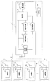
- FIG. 1 is a functional block diagram of an example of the power supply system according to the first embodiment.
- a vehicle 1 is, for example, an electric vehicle or a plug-in hybrid vehicle, a secondary battery 130 such as a lithium ion secondary battery or a nickel hydride secondary battery, and an in-vehicle communication device 2 for performing wireless communication.
- the in-vehicle communication device 2 includes a control unit 3, an antenna 4a (transmission / reception unit), a transmission processing unit 5, a power adjustment unit 6, a reception processing unit 7, and a power adjustment table 8A.
- the power supply apparatuses 91 to 9n include power supply side communication apparatuses 101 to 10n for performing wireless communication, respectively.
- the power supply side communication devices 101 to 10n include antennas 111 to 11n and communication units 121 to 12n, respectively.
- any one of the power feeding devices 91 to 9n when any one of the power feeding devices 91 to 9n is shown, it is referred to as a power feeding device 9. Further, when any one of the power supply side communication devices 101 to 10n is indicated, it is referred to as a power supply side communication device 10. In addition, when any one of the antennas 111 to 11n is shown, it is referred to as an antenna 11. Further, when any one of the communication units 121 to 12n is indicated, it is referred to as a communication unit 12.
- the function of the in-vehicle communication device 2 according to the first embodiment will be described.
- the in-vehicle communication device 2 is driven by power supplied from the secondary battery 130.
- the in-vehicle communication device 2 performs wireless communication with the power supply side communication devices 101 to 10n included in the power supply devices 91 to 9n.
- the control unit 3 controls the operations of the antenna 4a, the transmission processing unit 5, the power adjustment unit 6, and the reception processing unit 7.
- the control unit 3 searches for a power feeding device 9 that can communicate and accept power feeding from the power feeding devices 91 to 9n (whether the power feeding device 9 can receive a signal transmitted from the antenna 4a).
- An inquiry signal (for confirmation) is generated and output to the transmission processing unit 5.
- the inquiry signal is input to the antenna 4a via the transmission processing unit 5, and is transmitted from the antenna 4a to the power feeding apparatuses 91 to 9n by broadcast.
- control unit 3 controls the power adjustment unit 6 based on the value of the transmission output of the inquiry signal supplied to the antenna 4a stored in the power adjustment table 8A (hereinafter referred to as the transmission output value) to The adjustment unit 6 adjusts the transmission output of the inquiry signal.
- the control unit 3 controls the power adjusting unit 6 to repeatedly transmit the inquiry signal from the antenna 4a to the power feeding devices 91 to 9n while gradually reducing the transmission output of the inquiry signal.
- control unit 3 determines whether or not the response signal is received by the antenna 4a.
- the response signal is a signal transmitted from the power feeding device 9 to the vehicle 1 when the power feeding side communication device 10 receives the inquiry signal.
- the control unit 3 determines that the response signal is received from only one power supply device 9, the control unit 3 performs pairing (authentication processing) with the power supply device 9 that has transmitted the response signal.
- the determination of the number of power supply apparatuses 9 that have transmitted response signals includes, for example, an identifier in the response signal transmitted from the power supply apparatus 9.
- the vehicle-mounted communication apparatus 2 should just determine the number of the electric power feeders 9 which transmitted the response signal based on the kind of identifier which the received response signal contains.
- control unit 3 may perform control associated with transmission / reception of signals used for communication with the power supply device 9 and other devices.
- the antenna 4a transmits the input inquiry signal to the power supply apparatuses 91 to 9n by broadcast. Further, when receiving the response signal, the antenna 4 a outputs the received response signal to the reception processing unit 7.
- the antenna 4a may be used for transmission / reception of signals used for communication with the power supply device 9 and other devices in addition to the inquiry signal and the response signal.
- the transmission processing unit 5 converts the digital signal input from the control unit 3 into an analog signal for transmission from the antenna 4a, and outputs the analog signal to the antenna 4a.
- the transmission processing unit 5 converts an inquiry signal input as a digital signal from the control unit 3 into an analog signal and outputs the analog signal to the antenna 4a.
- the transmission processing unit 5 may encode the digital signal input from the control unit 3 and then convert it into an analog signal.
- the power adjustment unit 6 adjusts the transmission output of the signal transmitted from the antenna 4 a based on the control signal input from the control unit 3. For example, the power adjustment unit 6 adjusts the transmission output of the analog signal input from the transmission processing unit 5 according to the request for the control signal input from the control unit 3.
- the reception processing unit 7 converts the analog signal received by the antenna 4 a into a digital signal and outputs it to the control unit 3. For example, the reception processing unit 7 performs a process of converting a response signal input as an analog signal from the antenna 4 a into a digital signal and outputting the digital signal to the control unit 3.
- the reception processing unit 7 may convert the analog signal into a digital signal, decode the digital signal, and output the decoded digital signal to the control unit 3.
- the function of the power supply side communication device 10 will be described.
- the power supply side communication device 10 performs wireless communication with the in-vehicle communication device 2 included in the vehicle 1.
- the antenna 11 transmits a response signal input from the communication unit 12 to the vehicle 1. Further, when receiving the inquiry signal, the antenna 11 outputs the received inquiry signal to the communication unit 12.
- the antenna 11 may transmit and receive signals used for communication with the vehicle 1 and other devices in addition to the inquiry signal and the response signal.
- the communication unit 12 When the inquiry signal is input from the antenna 11, the communication unit 12 outputs a response signal to the antenna 11. However, the communication unit 12 does not output a response signal to the antenna 11 when the installed power feeding device 9 is in use.
- the communication unit 12 may perform control associated with transmission / reception of signals used for communication with the power supply device 9 and other devices in addition to the inquiry signal and the response signal.
- the communication unit 12 includes a control unit, a transmission processing unit, and a reception processing unit. And the control part of the communication part 12 produces
- the transmission processing unit of the communication unit 12 converts the response signal input as a digital signal into an analog signal and outputs the analog signal to the antenna 11.
- the reception processing unit of the communication unit 12 converts the inquiry signal input as an analog signal from the antenna 11 into a digital signal and outputs the digital signal to the control unit of the communication unit 12.
- FIG. 2 is a hardware configuration example of an embodiment of the communication apparatus.
- the communication device (the in-vehicle communication device 2 and the power supply side communication device 10) includes a control unit 201, a storage unit 202, a reading device 203, a recording medium 204, a display device 205, an input / output interface 206 (input / output I / O). F), a communication interface 207 (communication I / F), a power adjustment circuit 208, and an antenna 209. Each component is connected by a bus 200.
- the control unit 201, the storage unit 202, the reading device 203, the recording medium 204, the display device 205, the input / output interface 206 (input / output I / F), and the communication interface 207 (communication I / F) are collectively referred to as a computer.
- the control unit 201 controls the entire communication device.
- the control unit 201 of the in-vehicle communication device 2 functions as the control unit 3 in FIG.
- the control part 201 of the electric power feeding side communication apparatus 10 functions as a control part of the communication part 12 of FIG.
- the control unit 201 is, for example, a CPU, a multi-core CPU, an FPGA (Field Programmable Gate Array), a PLD (Programmable Logic Device), or the like.
- the storage unit 202 is, for example, a memory such as a ROM (Read Only Memory) and a RAM (Random Access Memory), or an HD (Hard Disk).
- the ROM stores a program such as a boot program.
- the RAM is used as a work area for the control unit 201.
- the HD stores an OS (Operating System), an application program, a program such as firmware, and various data.
- storage part 202 of the vehicle-mounted communication apparatus 2 has memorize
- the power adjustment table 8 ⁇ / b> A is not limited to the storage unit 202 of the in-vehicle communication device 2, and can be connected by another storage unit included in the vehicle 1 or the communication interface 207 as long as the control unit 201 of the in-vehicle communication device 2 can be accessed. May be stored in a server on the network 210.
- a communication control program may be stored in the storage unit 202 of the in-vehicle communication device 2. And when starting communication control, the control part 201 of the vehicle-mounted communication apparatus 2 reads a communication control program to RAM. Thereby, the control part 201 of the vehicle-mounted communication apparatus 2 functions as the control part 3 by using RAM as a work space.
- the communication control program is connected not only to the storage unit 202 of the in-vehicle communication device 2 but also to another storage unit included in the vehicle 1 or the communication interface 207 as long as the control unit 201 of the in-vehicle communication device 2 is accessible. May be stored in a server on the network 210.
- the communication control program may be stored in the storage unit 202 of the power supply side communication device 10. And when starting communication control, the control part 201 of the electric power feeding side communication apparatus 10 reads a communication control program to RAM. Thereby, the control part 201 of the electric power feeding side communication apparatus 10 functions as a control part of the communication part 12 by using RAM as a work space.
- the communication control program is not limited to the storage unit 202 of the power supply side communication device 10 but may be another storage unit included in the power supply device 9 or the communication interface 207 as long as the control unit 201 of the power supply side communication device 10 is accessible. It may be stored in a server on the network 210 connected by.
- HD Hard Disk Drive
- the reading device 203 is controlled by the control unit 201 and reads / writes data on the removable recording medium 204. Then, the reading device 203 of the in-vehicle communication device 2 may read the communication control program recorded in the recording medium 204 and store it in the storage unit 202 of the in-vehicle communication device 2. Further, the reading device 203 of the power supply side communication device 10 may read the communication control program recorded on the recording medium 204 and store it in the storage unit 202 of the power supply side communication device 10.
- the reading device 203 may be, for example, FDD (Floppy Disk Drive), CDD (Compact Disc Drive), DVDD (Digital Versatile Disk Drive), BDD (Blu-ray DiscUsU: registered trademark). It is.
- the recording medium 204 stores various data.
- the recording medium 204 is connected to the bus 200 via the reading device 203, and data is read / written by the control unit 201 controlling the reading device 203.
- the recording medium 204 may store a charge control program.
- the recording medium 204 is, for example, an FD (Floppy Disk), a CD (Compact Disc), a DVD (Digital Versatile Disk), a BD (Blu-ray Disk: registered trademark), and a flash memory.
- the display device 205 is connected to the bus 200 and is controlled by the control unit 201 to display various types of information.
- the display device 205 is, for example, a CRT (Cathode Ray Tube), an LCD (Liquid Crystal Display), a PDP (Plasma Display Panel), or an OELD (Organic Electroluminescence Display).
- the input / output interface 206 is connected to, for example, a keyboard, a mouse, a touch panel, a scanner, and a printer, receives information input by the connected device, and outputs the information to the control unit 201 via the bus 200. In addition, when the information output from the control unit 201 is input via the bus 200, the input / output interface 206 outputs the information to various connected devices.
- the communication interface 207 communicatively connects a communication device and another device via a network 210 such as power line communication, LAN (Local Area Network), wireless communication, or the Internet.
- the communication interface 207 of the in-vehicle communication device 2 functions as the transmission processing unit 5 and the reception processing unit 7 in FIG.
- the communication interface 207 of the power supply side communication device 10 functions as a transmission processing unit and a reception processing unit of the communication unit 12 in FIG.
- the communication interface 207 is, for example, a modem or a LAN adapter.
- the power adjustment circuit 208 adjusts the transmission output of the analog signal input from the control unit 201 via the communication interface 207, and outputs the analog signal to the antenna 209.
- the power adjustment circuit 208 functions as the power adjustment unit 6 in FIG.
- the power adjustment circuit 208 is, for example, an amplifier circuit that can switch the amplification factor.
- the antenna 209 transmits and receives radio signals.
- the antenna 209 of the vehicle-mounted communication apparatus 2 functions as the antenna 4a of FIG.
- the antenna 209 of the power supply side communication device 10 functions as the antenna 11 of FIG.
- the antenna 209 includes at least one of a non-directional antenna such as a whip antenna, a directional antenna such as a dipole antenna, and a directivity-switchable antenna such as an array antenna (registered trademark).
- FIG. 3 is a data example of a power adjustment table used for setting the transmission power value of the inquiry signal.
- the power adjustment table 8A according to the first embodiment will be described.
- the power adjustment table 8A shown in FIG. 3 for example, as shown in the power adjustment table 301, three output levels and transmission output values [W] corresponding to the respective output levels (hereinafter, [W] are omitted). .) Is stored.
- the output levels are not limited to three, and any number of two or more may be stored.
- the output level and the transmission output value corresponding to each output level are arbitrarily set by the user.
- the output level is an identifier for identifying the transmission output value stored in the power adjustment table 301.
- level 1, level 2, and level 3 are set as output levels.
- the transmission output value is a value that is output to the power adjustment unit 6 as the output of the inquiry signal when the control unit 3 selects the output level.
- the power adjustment unit 6 converts the power of the inquiry signal input from the transmission processing unit 5 into the input transmission output value and outputs it to the antenna 4a.
- the transmission output value is set such that A [W] ⁇ B [W] ⁇ C [W].
- an output set value and a power value [W] (hereinafter, [W] is omitted) are stored. good.
- the power value corresponding to each output setting value is arbitrarily set by the user.
- the output set value is an identifier for identifying the power value stored in the power adjustment table 302.
- the upper limit value is an identifier corresponding to the power value at the maximum output of the transmission output value.
- the differential power value indicates the difference between the original transmission output value when the output level of the transmission output value changes by one step and the transmission output value after the change.
- the lower limit value is an identifier corresponding to the power value at the minimum output of the transmission output value.
- the power value is a power value corresponding to each output setting value.
- D [W], E [W], and F [W] are set as the power values.
- FIG. 4 is an explanatory diagram illustrating an example of processing for specifying a communication destination according to the first embodiment.
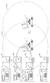
- FIG. 5 is an explanatory diagram showing an example of display contents of the display device.
- the antenna 4a is a non-directional antenna in FIG. 4 and that the values shown in the power adjustment table 301 in FIG. 3 are stored in the power adjustment table 8A.
- the antenna 4a is illustrated separately from the in-vehicle communication device 2, but is included in the in-vehicle communication device 2.
- the antennas 111 to 11n are illustrated separately from the power supply side communication devices 101 to 10n, but are included in the power supply side communication devices 101 to 10n, respectively.
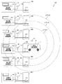
- a plurality of power supply apparatuses 9 are installed in the power supply facility 400.
- 4 are positions where the vehicle 1 is parked when the secondary battery 130 provided in the vehicle 1 is charged in a non-contact manner.
- Coils 411 to 41n in FIG. 4 are coils for transmitting and receiving power and transmitting and receiving communication signals in a non-contact manner with a coil (not shown) provided in the vehicle 1.
- the power supply area 40 is referred to.
- any one of the coils 411 to 41n it is called a coil 41.
- the inquiry signal of the transmission output C [W] corresponding to the transmission output value of level 3 is transmitted to the broadcast from the antenna 4a of the vehicle-mounted communication device 2.
- the antennas 112 to 115 within the range (hereinafter referred to as a communication area) included in the level 3 broken line shown in FIG. 4 receive the inquiry signal transmitted from the in-vehicle communication device 2.
- the power supply side communication devices 102 to 105 transmit response signals including the identifiers of the power supply devices 92 to 95 to which the power supply side communication devices 102 to 105 belong to the in-vehicle communication device 2.
- the in-vehicle communication device 2 receives response signals transmitted from the power supply devices 92 to 95. Then, the in-vehicle communication device 2 reads the identifier included in the response signal, and determines the power supply devices 92 to 95 that are the transmission source of the response signal. Then, as shown in the display screen 501 of FIG. 5, the in-vehicle communication device 2 uses power supply devices 92 to 95 that can be connected to the display device 205 of the in-vehicle communication device 2 (may be a display device mounted on the vehicle 1). indicate.
- the in-vehicle communication device 2 transmits a transmission output inquiry signal corresponding to the transmission output value of level 2 from the antenna 4a to the broadcast.
- the antennas 113 to 115 in the level 2 communication area shown in FIG. 4 receive the inquiry signal.
- the power supply side communication devices 103 to 105 transmit response signals including the identifiers of the power supply devices 93 to 95 to which the power supply side communication devices 103 to 105 belong to the in-vehicle communication device 2.
- the in-vehicle communication device 2 receives the response signals transmitted from the power feeding devices 93 to 95.
- the in-vehicle communication device 2 reads the identifier included in the response signal and determines the power supply devices 93 to 95 that are the transmission source of the response signal. Then, the in-vehicle communication device 2 displays the power feeding devices 93 to 95 that can be communicably connected to the display device 205 of the in-vehicle communication device 2.
- the in-vehicle communication device 2 transmits an inquiry signal of transmission output corresponding to the transmission output value of level 1 from the antenna 4a to the broadcast.
- the antenna 114 in the communication area of level 1 shown in FIG. 4 receives the inquiry signal.
- the power supply side communication device 104 transmits a response signal including the identifier of the power supply device 94 to which it belongs to the in-vehicle communication device 2.
- the in-vehicle communication device 2 receives only the response signal transmitted from the power supply device 94.
- the in-vehicle communication device 2 displays a power supply device 94 capable of communication connection on the display device 205 of the in-vehicle communication device 2 as shown in a display screen 502 in FIG.
- the in-vehicle communication device 2 identifies the power supply side communication device 104 as a communication destination and performs pairing.
- the power feeding device 94 that communicates with the vehicle 1 is displayed on the display screen of the display device 205 of the in-vehicle communication device 2 as a display screen 503.
- a display screen 504 indicating that communication with the vehicle 1 is performed may be displayed on the display screen of the display device 205 of the power supply side communication device 10 of the power supply device 94.
- the in-vehicle communication device 2 receives the inquiry signal to be transmitted stepwise (gradually) to each power supply side communication device 10 until the power supply side communication device 10 that transmits a response signal to the inquiry signal becomes one unit. Reduce the transmission output.
- the in-vehicle communication device 2 pairs with the power supply side communication device 10 when the power supply side communication device 10 having a response signal returned becomes one.
- the in-vehicle communication device 2 displays the identification number (read from the identifier included in the response signal) of the power supply device 9 to which the paired power supply side communication device 10 belongs to the display device 205 of the in-vehicle communication device 2.
- the in-vehicle communication device 2 guides the user to the power supply device 9 to which the paired power supply side communication device 10 belongs.
- the user moves the vehicle 1 to the position of the power supply device 9 displayed on the display device 205 of the in-vehicle communication device 2, thereby charging the secondary battery 130 included in the vehicle 1 with the power supply device 9 capable of communication connection. can do.
- the power supply side communication device 10 Even if the power supply side communication device 10 is within the range in which the inquiry signal from the in-vehicle communication device 2 can be received, and the power supply device 9 to which the power supply side communication device 10 belongs is in use, the power supply side communication device 10 It is not necessary to send back a response signal. Thereby, only the response signal from the power feeding device 9 that can be communicably connected to the vehicle 1 can be transmitted, and only the power feeding device 9 that can be communicably connected to the vehicle 1 can be notified.
- a plurality of power supply devices 9 to which the vehicle 1 can be connected for communication are displayed on the display device 205 of the in-vehicle communication device 2.
- the user may select the power supply side communication device 10 as the communication destination from the power supply devices 9 displayed on the display device 205 of the in-vehicle communication device 2.
- the vehicle-mounted communication apparatus 2 makes the vehicle-mounted communication apparatus 2 which the vehicle 1 has, and the electric power feeding side communication apparatus 10 which the selected electric power feeding apparatus 9 has paired.
- the in-vehicle communication device 2 may not display the display screen 501.
- the power feeding device 9 that does not include the vehicle 1 in the signal communication area is not recognized as the power feeding device 9 that can be communicably connected in the in-vehicle communication device 2.
- the transmission output of the inquiry signal is reduced stepwise using the following equation (1) to establish communication connection
- Possible power supply devices 9 may be specified.
- the response signal is accepted only within a predetermined time after the inquiry signal is transmitted.
- the in-vehicle communication device 2 performs pairing with the power supply device 9.
- the in-vehicle communication device 2 sends an inquiry signal whose transmission output is smaller than the inquiry signal transmitted last time to an unspecified number of power supplies. Transmit to device 9 (transmit to broadcast).
- the clock of the CPU of the control unit 201 of the in-vehicle communication device 2 may be counted, or a time counting unit such as a counter circuit may be provided separately.
- a time counting unit such as a counter circuit
- any method may be used as appropriate as long as mutual authentication is possible, such as a 3-way handshake.
- any method may be used as appropriate as long as mutual authentication is possible, such as a 3-way handshake.
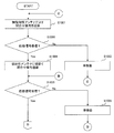
- FIG. 6 is a flowchart illustrating the processing contents for specifying the communication destination according to the first embodiment.
- the flowchart shown in FIG. 6 shows the process of specifying the communication destination described with reference to FIG. The following description will be given with reference to FIG. Further, in the following description, it is assumed that the antenna 4a is an omnidirectional antenna and that the values shown in the power adjustment table 301 in FIG. 3 are stored in the power adjustment table 8A.
- the in-vehicle communication device 2 of the vehicle 1 determines whether or not the vehicle 1 has entered the power supply facility 400 (S601). Then, the in-vehicle communication device 2 repeats the process of S601 until it is determined that the vehicle 1 has entered the power supply facility 400 (No in S601).
- the in-vehicle communication device 2 is, for example, that the vehicle 1 has entered the power supply facility 400 when an instruction to start a process for specifying a communication destination is input by the user via the input / output interface 206 of the in-vehicle communication device 2.
- a determination is made (Yes in S601), and an inquiry signal is transmitted to the broadcast (S602).
- the transmission output of the inquiry signal at this time is level 3, and the inquiry signal is transmitted over a wide range.
- an infrared transmitter is installed near the entrance of the power supply facility 400, and the vehicle 1 is provided with an infrared receiver.
- the in-vehicle communication device 2 may determine that the vehicle 1 has entered the power supply facility 400 when receiving a signal that the vehicle 1 has entered the power supply facility 400 from the infrared receiver. Note that the present invention is not limited to this, and if it can be determined that the vehicle 1 has entered the power supply facility 400, a method using various sensors may be selected as appropriate.
- the vehicle-mounted communication apparatus 2 determines whether the response signal transmitted from the electric power feeder 9 was received (S603). If the in-vehicle communication device 2 determines that the response signal transmitted from the power supply device 9 has not been received (No in S603), the user moves the vehicle 1 in the direction of each power supply device 9 (S604), and then S602. Perform the following process. Note that the movement of the vehicle 1 by the user is arbitrarily performed by the user during the process of specifying the communication destination shown in FIG.
- the vehicle-mounted communication device 2 determines whether the response signal is received from only one power supply device 9 or not. (S605). And if the vehicle-mounted communication apparatus 2 determines with having received the response signal from the several electric power feeder 9, (No in S605), it will determine whether the transmission output of an inquiry signal will be lowered
- the pairing process is executed manually (S608).
- the in-vehicle communication device 2 receives response signals from the plurality of power supply devices 9 when the transmission output is an inquiry signal whose level is 1, the display screen 501 is displayed on the display screen of the display device 205 of the in-vehicle communication device 2.
- a plurality of power supply apparatuses 9 that can be connected to each other are displayed.
- the user selects the power supply device 9 to be connected for communication from among the plurality of power supply devices 9 displayed on the display device 205 of the in-vehicle communication device 2.
- the in-vehicle communication device 2 performs a pairing process with an arbitrary power supply side communication device 10.
- the vehicle-mounted communication apparatus 2 determines whether pairing with the selected electric power feeding side communication apparatus 10 was completed (S609). If the in-vehicle communication device 2 determines that pairing with the selected power supply side communication device 10 has failed (S609), the in-vehicle communication device 2 executes the processing of S608 and selects a power supply device 9 different from the power supply device 9 selected last time by the user. Let In addition, when the in-vehicle communication device 2 cannot be paired with all the communication connectable power supply devices 9, the communication connection may be impossible and the processing may be terminated, or the processing of S604 may be executed again.
- the reason why pairing with the power feeding device 9 displayed on the display screen 501 is not possible is that the vehicle 1 requests pairing to the power feeding device 9 because the selected power feeding device 9 and another vehicle have paired first.
- the case where the signal etc. for doing so are exclusive is considered.
- the in-vehicle communication device 2 determines that the power supply side communication device 10 of the selected power supply device 9 has been paired (Yes in S609), the power supply device 9 having the power supply side communication device 10 paired with the display device 205. The identification number of the paired power supply device 9 is displayed. As a result, the user is guided to the paired power supply device 9. Thereafter, when the vehicle 1 is moved to the power supply area 40 of the power supply device 9 paired by the user, the vehicle 1 transmits a signal indicating that charging of the secondary battery 130 of the vehicle 1 is started to the paired power supply device 9. (S610). Thereby, charging of the secondary battery 130 of the vehicle 1 is started. During charging, a signal including information necessary for controlling charging is transmitted and received between the in-vehicle communication device 2 and the paired power supply side communication device 10.
- the in-vehicle communication device 2 when the inquiry signal is transmitted to the broadcast while the transmission output is gradually reduced, and the response signal is received from only one power supply device 9, the power supply device 9 Pairing is automatically performed with the power supply side communication device 10 having the power supply. Thereby, the in-vehicle communication device 2 can automatically identify the power supply device 9 closest to the vehicle 1 among the power supply devices 9 capable of communication connection as the power supply device 9 of the communication destination and perform pairing.
- the power supply device 9 closest to the vehicle 1 among the power supply devices 9 that can be connected to each other is automatically specified as the power supply device 9 that is the communication destination.
- the device 9 and the plurality of vehicles 1 can be in one-to-one correspondence.
- FIG. 7 is a functional block diagram of an example of the power supply system according to the second embodiment.
- the in-vehicle communication device 2 according to the second embodiment includes an omnidirectional antenna 4b and a directional antenna 4c instead of the antenna 4a of the in-vehicle communication device 2 according to the first embodiment. Furthermore, the in-vehicle communication device 2 according to the second embodiment includes an antenna switching unit 13 that switches an antenna used for signal transmission / reception between the antenna 4b and the antenna 4c.
- the antenna 4b is an omnidirectional antenna, and transmits an inquiry signal input from the power adjustment unit 6 to the power supply apparatuses 91 to 9n by broadcast. Further, when receiving the response signal, the antenna 4 b outputs the received response signal to the reception processing unit 7.
- the antenna 4b may be used for transmission / reception of signals used for communication with the power supply device 9 and other devices in addition to the inquiry signal and the response signal.
- the antenna 4 c is an antenna having directivity, and is installed so that the directivity faces the traveling direction of the vehicle 1.
- an antenna having a main lobe and a back lobe may be used as the antenna 4c.
- the antenna 4 c is preferably installed so that the main lobe faces the front of the vehicle 1. Thereby, when the vehicle 1 is moving forward, the directivity in the traveling direction of the antenna 4c is ensured by the main lobe. When the vehicle 1 is backing, the directivity in the traveling direction of the antenna 4c is ensured by the back lobe.
- the traveling direction when the vehicle 1 is backing may have the same directivity as the traveling direction when the vehicle 1 is moving forward. good.
- the directivity of the antenna 4c is not limited to the traveling direction of the vehicle 1, and may be set so as to face an arbitrary direction of the user.
- the traveling direction of the vehicle 1 is assumed to be a forward direction.
- the directivity of the antenna 4c shall be facing the front.
- the antenna 4c transmits the inquiry signal input from the power adjustment unit 6 to the power supply apparatuses 91 to 9n by broadcast. Further, when receiving the response signal, the antenna 4 c outputs the received response signal to the reception processing unit 7.
- the antenna 4c may be used for transmission / reception of signals used for communication with the power feeding device 9 and other devices in addition to the inquiry signal and the response signal.
- the antenna switching unit 13 switches the antenna used for signal transmission / reception between the antenna 4b and the antenna 4c.
- FIG. 2 is a hardware configuration example of an embodiment of the communication apparatus.
- the antenna 209 of the in-vehicle communication device 2 includes a directional antenna and an omnidirectional antenna, and a switching circuit that switches use of each. Thereby, the antenna 209 of the in-vehicle communication device 2 transmits and receives radio signals by switching between the non-directional antenna and the directional antenna. And the antenna 209 of the vehicle-mounted communication apparatus 2 of Embodiment 2 functions as the antenna 4b, the antenna 4c, and the antenna switching part 13 of FIG. Moreover, you may use the coil with which the vehicle 1 is provided instead of the antenna 4b of the vehicle-mounted communication apparatus 2 as the antenna 4b.
- FIG. 8 is a data example of a power adjustment table used for setting the transmission power value of the inquiry signal.
- the output level ⁇ of the omnidirectional antenna 4b and the transmission output value ⁇ [W] (hereinafter referred to as the output level ⁇ ). , [W] is omitted).
- the transmission output value ⁇ corresponding to the output level is arbitrarily set by the user.
- the output level ⁇ is an identifier for identifying the transmission output value ⁇ of the antenna 4b stored in the power adjustment table 801.
- level 3 is set as the output level ⁇ .
- the transmission output value ⁇ is a value that is output to the power adjustment unit 6 as the output of the inquiry signal when the control unit 3 sets the output level ⁇ to level 3.
- the power adjustment unit 6 sets the power of the inquiry signal input from the transmission processing unit 5 to the input transmission output value ⁇ and outputs it to the antenna 4b.
- C [W] is set as the transmission output value ⁇ .
- the power adjustment table 8B includes, for example, as shown in the power adjustment table 801, three output levels ⁇ of the directional antenna 4c and transmission output values ⁇ [W] (hereinafter referred to as the output levels ⁇ ). , [W] is omitted).
- the output level ⁇ is not limited to three but may be stored in an arbitrary number of two or more. Further, the output level ⁇ and the transmission output value ⁇ corresponding to each output level ⁇ are arbitrarily set by the user.
- the output level ⁇ is an identifier for identifying the transmission output value ⁇ stored in the power adjustment table 801.
- level 1, level 2, and level 3 are set as the output level ⁇ .
- the transmission output value ⁇ is a value that is output to the power adjustment unit 6 as the output of the inquiry signal when the control unit 3 selects the output level ⁇ .
- the power adjustment unit 6 outputs the power of the inquiry signal input from the transmission processing unit 5 to the antenna 4c as the input transmission output value ⁇ .
- the transmission output value ⁇ is set such that A [W] ⁇ B [W] ⁇ C [W].
- the output set value ⁇ and the power value ⁇ [W] may be set.
- the power value ⁇ corresponding to each output set value ⁇ is arbitrarily set by the user.
- the output set value ⁇ is an identifier for identifying the power value ⁇ stored in the power adjustment table 802.
- the upper limit value is an identifier corresponding to the power value at the maximum output of the transmission output value ⁇ .
- the differential power value indicates the power value of the difference between the original transmission output value ⁇ when the output level of the transmission output value ⁇ is changed by one step and the transmission output value ⁇ after the change.
- the lower limit value is an identifier corresponding to the power value at the minimum output of the transmission output value ⁇ .
- the power value ⁇ is a power value corresponding to each output set value ⁇ .
- D [W], E [W], and F [W] are set as the power value ⁇ .
- FIG. 9 is an explanatory diagram illustrating an example of processing for specifying a communication destination according to the second embodiment.
- the antenna 4b is an omnidirectional antenna
- the antenna 4c is a directional antenna
- the power adjustment table 8B has values shown in the power adjustment table 801 of FIG. It is assumed that it is stored.
- the same components as those of the first embodiment described with reference to FIG. Further, it is assumed that the vehicle 1 is located in the communication area of the antennas 111 to 11n.
- the inquiry signal of the transmission output value C [W] corresponding to the transmission output value ⁇ of level 3 is broadcast from the antenna 4b of the in-vehicle communication device 2.
- the antennas 112 and 113 in the communication area of level 3 shown in FIG. 9 receive the inquiry signal transmitted from the in-vehicle communication device 2.
- the power supply side communication devices 102 and 103 transmit a response signal to the in-vehicle communication device 2.
- the in-vehicle communication device 2 receives the response signal transmitted from the power feeding devices 92 and 93.
- the in-vehicle communication device 2 determines that the vehicle 1 has entered the power supply facility 400.
- the in-vehicle communication device 2 reads the identifier included in the response signal and determines the power supply devices 92 and 93 that are the transmission source of the response signal. Then, the in-vehicle communication device 2 determines that the power feeding devices 92 and 93 are communicable, and the power feeding device 92 that can be communicably connected to the display device 205 of the in-vehicle communication device 2 (or a display device mounted on the vehicle 1). , 93 are displayed.
- the in-vehicle communication device 2 switches the antenna to be used to the antenna 4c. Then, an inquiry signal of the transmission output C [W] corresponding to the transmission output value ⁇ of level 3 is transmitted from the antenna 4c to the broadcast.
- the antennas 112 and 113 in the L3 communication area shown in FIG. 9 receive the inquiry signal transmitted from the in-vehicle communication device 2. Then, the power supply side communication devices 102 and 103 transmit a response signal to the in-vehicle communication device 2. Thereby, the in-vehicle communication device 2 receives the response signal transmitted from the power feeding devices 92 and 93.
- the in-vehicle communication device 2 reads the identifier included in the response signal, and determines that the power supply devices 92 and 93 that are the transmission source of the response signal are power supply devices that can be communicably connected. Further, the in-vehicle communication device 2 displays power supply devices 92 and 93 that can be connected to the display device 205 of the in-vehicle communication device 2.
- the in-vehicle communication device 2 transmits an inquiry signal of the transmission output B [W] corresponding to the transmission output value ⁇ of level 2 from the antenna 4c to the broadcast.
- the antennas 112 and 113 in the L2 communication area shown in FIG. 9 receive the inquiry signal transmitted from the in-vehicle communication device 2.
- the power supply side communication devices 102 and 103 transmit a response signal to the in-vehicle communication device 2.
- the in-vehicle communication device 2 receives the response signal transmitted from the power feeding devices 92 and 93.
- the in-vehicle communication device 2 reads the identifier included in the response signal, and determines that the power supply devices 92 and 93 that are the transmission source of the response signal are power supply devices that can be communicably connected. Further, the in-vehicle communication device 2 displays power supply devices 92 and 93 that can be connected to the display device 205 of the in-vehicle communication device 2.
- the in-vehicle communication device 2 transmits an inquiry signal of the transmission output A [W] corresponding to the transmission output value ⁇ of level 1 from the antenna 4c to the broadcast.
- the antenna 113 in the communication area of L1 shown in FIG. 9 receives the inquiry signal transmitted from the in-vehicle communication device 2.
- the power supply side communication device 103 transmits a response signal to the in-vehicle communication device 2.
- the in-vehicle communication device 2 receives the response signal transmitted from the power feeding device 93.
- the vehicle-mounted communication apparatus 2 reads the identifier contained in a response signal, and determines with the power supply apparatus 93 of the transmission source of a response signal being a power supply apparatus with which communication connection is possible.
- the in-vehicle communication device 2 displays a power supply device 93 that can be connected to the display device 205 of the in-vehicle communication device 2.
- the in-vehicle communication device 2 specifies (selects) the power supply side communication device 104 as a communication destination and performs pairing. When the pairing is completed, the in-vehicle communication device 2 displays on the display device 205 of the in-vehicle communication device 2 a display indicating that the pairing is performed with the power feeding device 93 that communicates with the vehicle 1.
- the transmission output of the inquiry signal is stepwise using the equation (1) when the antenna 4c is used. It is also possible to specify a power supply device 9 that can be reduced in size for communication connection.
- FIG. 10 is a flowchart illustrating processing contents for specifying a communication destination according to the second embodiment.
- the flowchart shown in FIG. 10 shows the process of specifying the communication destination described with reference to FIG.
- the antenna 4b is an omnidirectional antenna
- the antenna 4c is a directional antenna
- the power adjustment table 8B stores values shown in the power adjustment table 801 of FIG. It will be explained as a thing.
- the in-vehicle communication device 2 of the vehicle 1 transmits an inquiry signal to the broadcast from the non-directional antenna 4b when an instruction to start a process for specifying a communication destination is input by the user (1001).
- the transmission output of the inquiry signal at this time is level 3, and the inquiry signal is transmitted over a wide range.
- vehicle-mounted communication apparatus 2 determines whether the response signal was received from the electric power feeder 9 (S1002).
- S1001 Perform the following process. Note that the movement of the vehicle 1 by the user is arbitrarily performed by the user during the process of specifying the communication destination shown in FIG. Further, when it is determined that the response signal transmitted from the power feeding device 9 has not been received (No in S1002), the in-vehicle communication device 2 may be configured to execute the process of S1001 after a certain time.
- the vehicle-mounted communication apparatus 2 if it determines with the vehicle-mounted communication apparatus 2 having received the response signal transmitted from the 1 or more power supply apparatus 9 (it is Yes in S1002), it will determine with the vehicle 1 being located in the power supply facility 400.
- the antenna to be used is switched to the antenna 4c and an inquiry signal is transmitted.
- the inquiry signal transmission output at this time is set to level 3, and the inquiry signal is transmitted over a wide range (S1004).
- vehicle-mounted communication apparatus 2 determines whether the response signal was received from the electric power feeder 9 (S1005).
- the in-vehicle communication device 2 determines that the response signal transmitted from the power supply device 9 has not been received (No in S1005), after the user moves the vehicle 1 in the direction of each power supply device 9 (S1006), S1001 Perform the following process. Note that the movement of the vehicle 1 by the user is arbitrarily performed by the user during the process of specifying the communication destination shown in FIG. Further, when it is determined that the response signal transmitted from the power feeding device 9 has not been received (No in S1002), the in-vehicle communication device 2 may be configured to execute the process of S1001 after a certain time.
- the in-vehicle communication apparatus 2 performs the processes of S605 to S611 shown in FIG.
- the inquiry signal is first transmitted by the omnidirectional antenna 4b. Accordingly, it is determined whether or not the power feeding device 9 is in the communication area of the vehicle 1. When the power feeding device 9 is in the communication area of the vehicle 1, communication using the antenna 4 c having directivity automatically is performed. The process can be shifted to the process of specifying the previous power supply device 9.
- one or more power supply devices 9 that can be connected to communication are specified. To do.
- the specified power feeding device 9 is in a direction different from the traveling direction of the vehicle 1, the direction of the power feeding device 9 is indicated on the display device 205 of the vehicle 1, and the traveling direction of the vehicle 1 is identified. Guide the user to change direction. Thereafter, when the traveling direction of the vehicle 1 is directed to the specified power supply device 9, the process may be shifted to a process of specifying the communication destination power supply device 9 using the antenna 4 c having directivity.
- the power feeding device 9 can be efficiently captured in the main lobe of the radio wave that transmits the inquiry signal of the antenna 4c having directivity.
- map information in the power supply facility 400 is obtained when the in-vehicle communication device 2 connects to a server in the power supply facility 400 when the vehicle 1 enters the power supply facility 400.
- the vehicle-mounted communication apparatus 2 discriminate
- the position of the power supply device 9 may be determined based on the reception intensity of the response signal received from the power supply device 9 and the direction in which the response signal is transmitted.
- the in-vehicle communication device 2 of the vehicle 1 and the power supply side communication device 10 of the power supply device 9 are paired using the antenna 4c having directivity.
- the antenna that transmits the inquiry signal has directivity
- the power feeding device 9 that searches whether communication connection is possible is narrowed down in advance by the directivity of the antenna. Therefore, in the second embodiment, it is possible to narrow down to the power feeding device 9 in the traveling direction of the vehicle 1 and to search whether the communication connection with the vehicle 1 is possible or not. Therefore, the communication device for specifying the power feeding device 9 of the communication destination The processing load can be reduced.
- the omnidirectional antenna 4b may be omitted.
- the process from S1004 may be started using the antenna 4c having directivity.
- FIG. 11 is a functional block diagram of an example of the power supply system according to the third embodiment.
- FIG. 11 the same functions as those of the in-vehicle communication device 2 according to the second embodiment described in FIG.
- the functions of the power supply side communication devices 101 to 10n according to the third embodiment are the same as the functions of the power supply side communication devices 101 to 10n according to the first embodiment described in FIG. The description is omitted.
- the in-vehicle communication device 2 according to the third embodiment instead of the antenna 4b, the antenna 4c, and the antenna switching unit 13 of the in-vehicle communication device 2 according to the second embodiment, the directivity of the antenna 4d and the directivity of the antenna 4d are switched. And a directivity switching unit for switching the characteristics.
- the antenna 4d is switchable in directivity, and transmits an inquiry signal input from the power adjustment unit 6 to the power supply apparatuses 91 to 9n in a broadcast manner.
- the directivity switching unit 14 sets the main lobe so as to face the traveling direction of the vehicle 1. Further, when receiving the response signal, the antenna 4 d outputs the received response signal to the reception processing unit 7.
- the antenna 4d may be used for transmission / reception of signals used for communication with the power supply device 9 and other devices in addition to the inquiry signal and the response signal.
- the directivity switching unit 14 performs control to switch the directivity of the antenna 4d.
- FIG. 2 is a hardware configuration example of an embodiment of the communication apparatus.
- the antenna 209 of the in-vehicle communication device 2 includes an antenna that can switch directivity and a directivity switching circuit that switches the directivity of the antenna. Thereby, the antenna 209 of the in-vehicle communication device 2 transmits and receives radio signals by switching the directivity of the antenna.
- the antenna 209 of the in-vehicle communication device 2 functions as the antenna 4d and the directivity switching unit 14 in FIG. Further, as the antenna 4d of the in-vehicle communication device 2, a power feeding coil provided in the vehicle 1 may be used.
- a reactance value adjustment circuit may be used as the directivity switching circuit.
- the configuration of the antenna 209 is not particularly limited as long as the antenna 209 is a combination of an antenna capable of switching directivity and a directivity switching circuit.
- the configuration of the third embodiment is a configuration in which the antenna 4b is replaced with the antenna 4d in a non-directional state and the antenna 4c is replaced with a state in which the antenna 4d has directivity in the second embodiment.
- the operation of the third embodiment is an operation in which the directivity of the antenna is switched instead of switching the antenna in the process of S1004 in FIG. 10 in the process of specifying the communication destination of the second embodiment.
- the same operation as that of the second embodiment is realized by changing the directivity of the antenna 4d instead of the configuration of switching the antenna 4b and the antenna 4c of the second embodiment. Thereby, the same effect as Embodiment 2 can be acquired with one antenna.
- the power supply device capable of communication connection is displayed on the display device 205 of the in-vehicle communication device 2.
- the user arbitrarily selects one of the displayed power supply apparatuses that can be connected to the communication, and enters one of the power supply areas 401 to 40n. Thereafter, the processing of S602 to S611 shown in FIG. 6 is performed. Since the power supply side communication device 10 corresponding to the power supply area 40 selected by the user is closest to the vehicle, the power supply side communication device 10 corresponding to the power supply area 40 selected by the user is communicated with by performing the processing of S602 to S611. Specified.
- the power supply device capable of communication connection is displayed on the display device 205 of the in-vehicle communication device 2.
- the user arbitrarily selects one of the displayed power supply apparatuses that can be connected to the communication, and enters one of the power supply areas 401 to 40n.
- the inquiry signal is transmitted by switching to the directional antenna (S1004). Since the power supply side communication device 10 corresponding to the power supply area 40 selected by the user is closest to the vehicle, the power supply side communication device 10 corresponding to the power supply area 40 selected by the user is set as the communication destination by performing the processing from S1004. Identified.
- the direction of the main lobe of the antenna having directivity is not limited to the traveling direction of the vehicle 1.
Landscapes
- Engineering & Computer Science (AREA)
- Power Engineering (AREA)
- Transportation (AREA)
- Mechanical Engineering (AREA)
- Computer Networks & Wireless Communication (AREA)
- Life Sciences & Earth Sciences (AREA)
- Sustainable Development (AREA)
- Sustainable Energy (AREA)
- Signal Processing (AREA)
- General Health & Medical Sciences (AREA)
- Computing Systems (AREA)
- Medical Informatics (AREA)
- Health & Medical Sciences (AREA)
- Charge And Discharge Circuits For Batteries Or The Like (AREA)
- Electric Propulsion And Braking For Vehicles (AREA)
- Variable-Direction Aerials And Aerial Arrays (AREA)
- Transceivers (AREA)
- Transmitters (AREA)
- Radio Transmission System (AREA)
- Traffic Control Systems (AREA)
- Mobile Radio Communication Systems (AREA)
Abstract
車載通信装置2は、送信出力を段階的に小さくしながら問合せ信号をブロードキャストに送信し、1台の給電装置9からのみ応答信号を受信したときに、その給電装置9が有する給電側通信装置10と自動的にペアリングする。
Description
本発明は無線通信の技術に関する。
近年、電気自動車(Electric Vehicle)やプラグインハイブリッド車(Plug-in Hybrid Car)などの車両の充電に非接触充電が用いられている。非接触充電では、磁界共鳴方式や電磁誘導方式などの充電方式により、コイルを介して車両と給電装置との間で送受電が行なわれる。さらに、非接触充電では、充電用の電力の送受電だけでなく、車両と給電装置との間の通信も無線にすることで、充電および通信のためのケーブルを接続する必要をなくし、接触充電と比較して利便性を向上している。
関連技術として、DSRC車載器が、車両の上方に向かう幅広の指向性を有する広角アンテナと、前方に向かう幅狭の指向性を有する前方アンテナとを備える。そして、運転者がDSRC車載器本体の有するアンテナ切替用スイッチを切替えることによって、広角アンテナまたは前方アンテナを設定し、運転者が必要な信号のみを受信する技術が提案されている(例えば、特許文献1)。
関連技術として、車載無線装置が、指向性を切替可能なアンテナを備える。車載無線機は、料金所以外に設置された一般の路側機と通信を行なっているとき、アンテナの指向性を低仰角指向性に固定する。そして、車載無線機は、料金所に設置された路側機と通信を行なうとき、アンテナの指向性を中仰角指向性に切替える。これにより、運転者が必要な信号を受信する技術が提案されている(例えば、特許文献2)。
本発明は、車両と相互通信を行なう給電装置を特定する車載通信装置、および通信方法を提供することを目的とする。
本明細書で開示する車載通信装置のひとつに、送受信部と、電力調整部と、制御部とを備えるものがある。ここで、送受信部は、無線で信号を送受信する。電力調整部は、送受信部から送信する信号の送信出力の大きさを調整する。制御部は、送受信部から不特定多数の給電装置に受信確認する問合せ信号を送信し、問合せ信号に対する応答信号を複数の給電装置から受信すると、電力調整部を制御して、問合せ信号の送信出力の大きさを段階的に小さくしながら問合せ信号を繰り返し送信し、応答信号を1台の給電装置からのみ受信したときに、1台の給電装置が有する通信装置と信号の送受信をするための認証処理をする。
本明細書で開示する車載通信装置、および通信方法は、車両と相互通信を行なう給電装置を特定することができるという効果を奏する。
[実施形態1]
図1について説明する。
図1は、実施形態1の電力供給システムの一実施例の機能ブロック図である。
図1について説明する。
図1は、実施形態1の電力供給システムの一実施例の機能ブロック図である。
図1において、車両1は、例えば、電気自動車やプラグインハイブリッド車などであり、リチウムイオン二次電池、ニッケル水素二次電池などの2次電池130、および無線通信を行なうための車載通信装置2を備える。車載通信装置2は、制御部3、アンテナ4a(送受信部)、送信処理部5、電力調整部6、受信処理部7、および電力調整テーブル8Aを備える。給電装置91~9nは、それぞれ無線通信を行なうための給電側通信装置101~10nを備える。給電側通信装置101~10nは、それぞれアンテナ111~11n、および通信部121~12nを備える。なお、以下の説明では、給電装置91~9nの中のいずれか一つを示す場合、給電装置9という。また、給電側通信装置101~10nの中のいずれか一つを示す場合、給電側通信装置10という。また、アンテナ111~11nの中のいずれか一つを示す場合、アンテナ11という。また、通信部121~12nの中のいずれか一つを示す場合、通信部12という。
実施形態1に係る車載通信装置2の機能を説明する。
車載通信装置2は、2次電池130から供給される電力で駆動する。そして、車載通信装置2は、給電装置91~9nが備える給電側通信装置101~10nとの間で無線通信を行なう。
車載通信装置2は、2次電池130から供給される電力で駆動する。そして、車載通信装置2は、給電装置91~9nが備える給電側通信装置101~10nとの間で無線通信を行なう。
制御部3は、アンテナ4a、送信処理部5、電力調整部6、および受信処理部7の動作を制御する。
そして、制御部3は、給電装置91~9nの中から通信可能であり、かつ給電を受付可能な給電装置9を検索するための(給電装置9がアンテナ4aから送信される信号を受信できるか確認するための)問合せ信号を生成し、送信処理部5に出力する。これにより、問合せ信号は、送信処理部5を介してアンテナ4aに入力され、アンテナ4aから給電装置91~9nに向けてブロードキャストに送信される。
また、制御部3は、電力調整テーブル8Aに格納されているアンテナ4aに供給する問合せ信号の送信出力の値(以下、送信出力値という。)に基づいて電力調整部6を制御して、電力調整部6に問合せ信号の送信出力を調整させる。実施形態1の場合、制御部3は、電力調整部6を制御して、問合せ信号の送信出力を段階的に小さくしながら、問合せ信号をアンテナ4aから給電装置91~9nに繰り返し送信させる。
また、制御部3は、応答信号をアンテナ4aで受信したか否かを判定する。応答信号とは、給電側通信装置10が問合せ信号を受信すると給電装置9から車両1に送信する信号である。
そして、制御部3は、応答信号を1台の給電装置9からのみ受信したと判定したときに、その応答信号を送信してきた給電装置9とペアリング(認証処理)をする。なお、応答信号を送信してきた給電装置9の台数判定は、例えば、給電装置9から送信する応答信号に識別子を含ませる。そして、車載通信装置2は、受信した応答信号が含む識別子の種類に基づいて、応答信号を送信してきた給電装置9の台数を判定すれば良い。
また、制御部3は、問合せ信号や応答信号以外にも、給電装置9やその他の装置との通信に用いられる信号の送受信にともなう制御を行なっても良い。
アンテナ4aは、入力された問合せ信号を給電装置91~9nに向かってブロードキャストに送信する。また、アンテナ4aは、応答信号を受信すると、受信した応答信号を受信処理部7に出力する。なお、アンテナ4aは、問合せ信号や応答信号以外にも、給電装置9やその他の装置との通信に用いられる信号の送受信に用いても良い。
送信処理部5は、制御部3から入力されるデジタル信号を、アンテナ4aから送信するためにアナログ信号に変換し、アンテナ4aに出力する。例えば、送信処理部5は、制御部3からデジタル信号として入力される問合せ信号をアナログ信号に変換し、アンテナ4aに出力する。
また、送信処理部5は、制御部3から入力されるデジタル信号を符号化してからアナログ信号に変換しても良い。
電力調整部6は、制御部3から入力される制御信号に基づいて、アンテナ4aから送信する信号の送信出力を調整する。例えば、電力調整部6は、送信処理部5から入力されるアナログ信号の送信出力を、制御部3から入力される制御信号の要求に応じて調整する。
受信処理部7は、アンテナ4aで受信したアナログ信号をデジタル信号に変換し、制御部3に出力する。例えば、受信処理部7は、アンテナ4aからアナログ信号として入力される応答信号を、デジタル信号に変換し、制御部3に出力する処理をする。
また、受信処理部7は、アンテナ4aから入力された信号が符号化されている場合、アナログ信号をデジタル信号に変換した後、デジタル信号を復号化して制御部3に出力しても良い。
給電側通信装置10の機能を説明する。
給電側通信装置10は、車両1が備える車載通信装置2との間で無線通信を行なう。
給電側通信装置10は、車両1が備える車載通信装置2との間で無線通信を行なう。
アンテナ11は、通信部12から入力される応答信号を車両1に送信する。また、アンテナ11は、問合せ信号を受信すると、受信した問合せ信号を通信部12に出力する。なお、アンテナ11は、問合せ信号や応答信号以外にも、車両1やその他の装置との通信に用いられる信号の送受信を行なっても良い。
通信部12は、アンテナ11から問合せ信号が入力されると、応答信号をアンテナ11に出力する。ただし、通信部12は、設置されている給電装置9が使用中である場合には、応答信号をアンテナ11に出力しない。
なお、通信部12は、問合せ信号や応答信号以外にも、給電装置9やその他の装置との通信に用いられる信号の送受信にともなう制御を行なっても良い。
具体的には、通信部12は、制御部、送信処理部、受信処理部を備える。そして、通信部12の制御部は、デジタル信号として応答信号を生成し、その応答信号を送信処理部に出力する。通信部12の送信処理部は、デジタル信号として入力された応答信号をアナログ信号に変換して、アンテナ11に出力する。また、通信部12の受信処理部は、アンテナ11からアナログ信号として入力される問合せ信号を、デジタル信号に変換して、通信部12の制御部に出力する。
次に、図2について説明する。
図2は、通信装置の一実施例のハードウェア構成例である。
図2は、通信装置の一実施例のハードウェア構成例である。
図2において、通信装置(車載通信装置2、および給電側通信装置10)は、制御部201、記憶部202、読取装置203、記録媒体204、表示装置205、入出力インターフェイス206(入出力I/F)、通信インターフェイス207(通信I/F)、電力調整回路208、およびアンテナ209を備えている。また、各構成要素は、バス200により接続されている。なお、制御部201、記憶部202、読取装置203、記録媒体204、表示装置205、入出力インターフェイス206(入出力I/F)、通信インターフェイス207(通信I/F)をまとめてコンピュータという。
制御部201は、通信装置全体の制御をする。車載通信装置2の制御部201は、図1の制御部3として機能する。また、給電側通信装置10の制御部201は、図1の通信部12の制御部として機能する。そして、制御部201は、例えば、CPU、マルチコアCPU、FPGA(Field Programmable Gate Array)およびPLD(Programmable Logic Device)などである。
記憶部202は、例えば、ROM(Read Only Memory)およびRAM(Random Access Memory)などのメモリや、HD(Hard Disk)などである。そして、ROMは、ブートプログラムなどのプログラムを記憶している。RAMは、制御部201のワークエリアとして使用される。HDは、OS(Operating System)、アプリケーションプログラム、ファームウェアなどのプログラム、および各種データを記憶している。また、車載通信装置2の記憶部202は、図1の電力調整テーブル8Aを記憶している。なお、電力調整テーブル8Aは、車載通信装置2の記憶部202に限らず、車載通信装置2の制御部201がアクセス可能であれば、車両1が備える他の記憶部、または通信インターフェイス207で接続されるネットワーク210上のサーバに記憶されていても良い。
さらに、車載通信装置2の記憶部202に通信制御プログラムを記憶しても良い。そして、通信制御を開始するときに、車載通信装置2の制御部201は、通信制御プログラムをRAMに読み出す。これにより、車載通信装置2の制御部201は、RAMをワークスペースとして使用することにより、制御部3として機能する。なお、通信制御プログラムは、車載通信装置2の記憶部202に限らず、車載通信装置2の制御部201がアクセス可能であれば、車両1が備える他の記憶部、または通信インターフェイス207で接続されるネットワーク210上のサーバに記憶されていても良い。
また、給電側通信装置10の記憶部202に通信制御プログラムを記憶しても良い。そして、通信制御を開始するときに、給電側通信装置10の制御部201は、通信制御プログラムをRAMに読み出す。これにより、給電側通信装置10の制御部201は、RAMをワークスペースとして使用することにより、通信部12の制御部として機能する。なお、通信制御プログラムは、給電側通信装置10の記憶部202に限らず、給電側通信装置10の制御部201がアクセス可能であれば、給電装置9が備える他の記憶部、または通信インターフェイス207で接続されるネットワーク210上のサーバに記憶されていても良い。
なお、記憶部202がHDである場合、HDD(Hard Disk Drive)を介してバス200に接続され、HDDが制御部201に制御されることにより、データのリード/ライトが行なわれる。
読取装置203は、制御部201に制御され、着脱可能な記録媒体204のデータのリード/ライトを行なう。そして、車載通信装置2の読取装置203は、記録媒体204に記録された通信制御プログラムを読み出し、車載通信装置2の記憶部202に記憶しても良い。また、給電側通信装置10の読取装置203は、記録媒体204に記録された通信制御プログラムを読み出し、給電側通信装置10の記憶部202に記憶しても良い。そして、読取装置203は、例えば、FDD(Floppy Disk Drive)、CDD(Compact Disc Drive)、DVDD(Digital Versatile Disk Drive)、BDD(Blu-ray Disk Drive:登録商標)およびUSB(Universal Serial Bus)などである。
記録媒体204は、各種データが記憶される。そして、記録媒体204は、読取装置203を介してバス200に接続され、制御部201が読取装置203を制御することにより、データのリード/ライトが行なわれる。また、記録媒体204は、充電制御プログラムを保存しても良い。そして、記録媒体204は、例えば、FD(Floppy Disk)、CD(Compact Disc)、DVD(Digital Versatile Disk)、BD(Blu-ray Disk:登録商標)、およびフラッシュメモリなどである。
表示装置205は、バス200に接続され、制御部201に制御されることにより、各種情報を表示する。そして、表示装置205は、例えば、CRT(Cathode Ray Tube)、LCD(Liquid Crystal Display)、PDP(Plasma Display Panel)およびOELD(Organic Electroluminescence Display)などである。
入出力インターフェイス206は、例えば、キーボード、マウス、タッチパネル、スキャナ、およびプリンタなどと接続され、接続された装置で入力された情報を受信し、バス200を介して制御部201に出力する。また、入出力インターフェイス206は、制御部201から出力された情報がバス200を介して入力されると、接続された各種装置にその情報を出力する。
通信インターフェイス207は、電力線通信、LAN(Local Area Network)、無線通信、またはインターネットなどのネットワーク210を介して、通信装置と他の装置とを通信可能に接続する。そして、車載通信装置2の通信インターフェイス207は、図1の送信処理部5、および受信処理部7として機能する。また、給電側通信装置10の通信インターフェイス207は、図1の通信部12の送信処理部、および受信処理部として機能する。なお、通信インターフェイス207は、例えば、モデムやLANアダプタなどである。
電力調整回路208は、制御部201から通信インターフェイス207を介して入力されるアナログ信号の送信出力を調整してアンテナ209に出力する。そして、電力調整回路208は、図1の電力調整部6として機能する。また、電力調整回路208は、例えば、増幅率を切替可能な増幅回路などである。
アンテナ209は、無線信号の送受信をする。そして、車載通信装置2のアンテナ209は、図1のアンテナ4aとして機能する。また、給電側通信装置10のアンテナ209は、図1のアンテナ11として機能する。そして、アンテナ209は、ホイップアンテナなどの無指向性のアンテナ、ダイポールアンテナなどの指向性を有するアンテナ、アレーアンテナ(登録商標)などの指向性切替可能なアンテナのいずれか1本以上を備える。また、車載通信装置2のアンテナ4aの代わりに、車両1が備えるコイルをアンテナ4aとして用いても良い。
図3について説明する。
図3は、問合せ信号の送信電力値の設定に用いられる電力調整テーブルのデータ例である。
図3は、問合せ信号の送信電力値の設定に用いられる電力調整テーブルのデータ例である。
実施形態1に係る電力調整テーブル8Aの説明をする。
図3に示す電力調整テーブル8Aには、例えば、電力調整テーブル301に示されるように、3つの出力レベルと、各出力レベルに対応する送信出力値[W](以下、[W]を省略する。)が格納されている。なお、出力レベルは、3つに限定されるものではなく、2つ以上の任意の数だけ格納しておけば良い。また、出力レベルと、各出力レベルに対応する送信出力値は、ユーザにより任意に設定される。
図3に示す電力調整テーブル8Aには、例えば、電力調整テーブル301に示されるように、3つの出力レベルと、各出力レベルに対応する送信出力値[W](以下、[W]を省略する。)が格納されている。なお、出力レベルは、3つに限定されるものではなく、2つ以上の任意の数だけ格納しておけば良い。また、出力レベルと、各出力レベルに対応する送信出力値は、ユーザにより任意に設定される。
出力レベルは、電力調整テーブル301に格納されている送信出力値を識別するための識別子である。電力調整テーブル301においては、出力レベルとして、レベル1、レベル2、レベル3が設定されている。
また、送信出力値は、制御部3が出力レベルを選択したときに、問合せ信号の出力として電力調整部6に出力する値である。なお、電力調整部6は、送信出力値が入力されると、送信処理部5から入力される問合せ信号の電力を、入力された送信出力値にしてアンテナ4aに出力する。また、以下の説明においては、送信出力値は、A[W]<B[W]<C[W]となるように値が設定されているものとする。
電力調整テーブル8Aの別の一例としては、例えば、電力調整テーブル302に示されるように、出力設定値と、電力値[W](以下、[W]を省略する。)とを格納しても良い。なお、各出力設定値に対応する電力値は、ユーザにより任意に設定される。
出力設定値は、電力調整テーブル302に格納されている電力値を識別するための識別子である。上限値とは、送信出力値の最大出力時の電力値に対応する識別子である。差分電力値とは、送信出力値の出力レベルが一段階変化した時の元の送信出力値と、変化後の送信出力値との差を示している。また、下限値は、送信出力値の最小出力時の電力値に対応する識別子である。
また、電力値は、各出力設定値に対応する電力値である。図3の電力調整テーブル302において、電力値には、D[W]、E[W]、F[W]が設定されている。
図4について説明する。
図4は、実施形態1の通信先を特定する処理の一実施例を示す説明図である。
図4は、実施形態1の通信先を特定する処理の一実施例を示す説明図である。
図5について説明する。
図5は、表示装置の表示内容の一実施例を示す説明図である。
図5は、表示装置の表示内容の一実施例を示す説明図である。
以下の説明では、図4において、アンテナ4aが無指向性のアンテナであり、電力調整テーブル8Aには、図3の電力調整テーブル301に示す値が格納されているものとして説明する。なお、アンテナ4aは、車載通信装置2と別に図示しているが、車載通信装置2に含まれる。また、アンテナ111~11nは、給電側通信装置101~10nと別に図示しているが、それぞれ給電側通信装置101~10nに含まれる。
給電施設400には、複数の給電装置9が設置されている。また、図4の給電エリア401~40nは、各給電装置9に設けられ、車両1の備える2次電池130を非接触で充電するときに車両1が駐車する位置である。図4のコイル411~41nは、車両1の備えるコイル(図示しない)と、非接触で電力の送受電、および通信信号の送受信をするためのコイルである。なお、以下の説明では、給電エリア401~40nの中のいずれか一つを示す場合、給電エリア40という。また、コイル411~41nの中のいずれか一つを示す場合、コイル41という。
車両1の車載通信装置2は、給電施設400に進入すると、車載通信装置2のアンテナ4aからレベル3の送信出力値に対応する送信出力C[W]の問合せ信号をブロードキャストに送信する。このとき、図4に示すレベル3の破線に含まれる範囲(以下、通信エリアという。)内にあるアンテナ112~115が、車載通信装置2から送信された問合せ信号を受信する。すると、給電側通信装置102~105は、それぞれが属する給電装置92~95の識別子を含む応答信号を車載通信装置2に送信する。これにより、車載通信装置2は、給電装置92~95から送信される応答信号を受信することになる。そして、車載通信装置2は、応答信号に含まれる識別子を読み取り、応答信号の送信元の給電装置92~95を判別する。すると、車載通信装置2は、図5の表示画面501に示すように、通信接続可能な給電装置92~95を車載通信装置2の表示装置205(車両1が搭載する表示装置でも良い。)に表示する。
次に、車載通信装置2は、アンテナ4aからレベル2の送信出力値に対応する送信出力の問合せ信号をブロードキャストに送信する。このとき、図4に示すレベル2の通信エリア内にあるアンテナ113~115が、問合せ信号を受信する。すると、給電側通信装置103~105は、それぞれが属する給電装置93~95の識別子を含む応答信号を車載通信装置2に送信する。これにより、車載通信装置2は、給電装置93~95から送信される応答信号を受信することになる。そして、車載通信装置2は、応答信号に含まれる識別子を読み取り、応答信号の送信元の給電装置93~95を判別する。すると、車載通信装置2は、車載通信装置2の表示装置205に通信接続可能な給電装置93~95を表示する。
さらに、車載通信装置2は、アンテナ4aからレベル1の送信出力値に対応する送信出力の問合せ信号をブロードキャストに送信する。このとき、図4に示すレベル1の通信エリア内にあるアンテナ114が、問合せ信号を受信する。すると、給電側通信装置104は、属する給電装置94の識別子を含む応答信号を車載通信装置2に送信する。これにより、車載通信装置2は、給電装置94から送信される応答信号のみを受信することになる。そして、車載通信装置2は、図5の表示画面502に示すように、通信接続可能な給電装置94を車載通信装置2の表示装置205に表示する。
そして、車載通信装置2は、給電側通信装置104を通信先に特定し、ペアリングする。このとき、車両1と相互通信する給電装置94は、車載通信装置2の表示装置205の表示画面に、表示画面503のように表示される。また、給電装置94の給電側通信装置10の表示装置205の表示画面に、車両1と相互通信することを示す表示画面504を表示しても良い。
以上のように、車載通信装置2は、問合せ信号に対する応答信号を送信する給電側通信装置10が1台になるまで、段階的に(徐々に)各給電側通信装置10に送信する問合せ信号の送信出力を小さくする。そして、車載通信装置2は、応答信号の返信がある給電側通信装置10が1台になったときに、その給電側通信装置10とペアリングする。
さらに、車載通信装置2は、車載通信装置2の表示装置205にペアリングした給電側通信装置10が属する給電装置9の識別番号(応答信号に含まれる識別子から読み出す。)を表示する。これにより、車載通信装置2は、ペアリングした給電側通信装置10が属する給電装置9に、ユーザを誘導する。そして、ユーザは、車載通信装置2の表示装置205に表示された給電装置9の位置に車両1を移動させることにより、通信接続可能な給電装置9で車両1の備える2次電池130の充電をすることができる。
また、給電側通信装置10は、車載通信装置2からの問合せ信号を受信できる範囲内にある給電側通信装置10であっても、属する給電装置9が使用中である場合、車載通信装置2に応答信号の返信をしなくても良い。これにより、車両1に通信接続可能な給電装置9からの応答信号のみを送信し、車両1に通信接続可能な給電装置9のみを通知することができる。
また、車載通信装置2による通信先の給電側通信装置10を特定する処理過程において、車両1が通信接続可能な複数の給電装置9を、車載通信装置2の表示装置205に表示させた。このときに、ユーザは、車載通信装置2の表示装置205に表示された給電装置9の中から通信先の給電側通信装置10を選択しても良い。そして、車載通信装置2は、車両1が有する車載通信装置2と、選択された給電装置9が有する給電側通信装置10とをペアリングさせる。これにより、車両1が通信接続可能な複数の給電装置9の中から、ユーザの判断で通信接続する給電装置9を選択することができる。なお、以下に説明する実施形態2、および実施形態3においても同様である。また、ユーザに通信先の給電装置9を選択させる構成を省略する場合、車載通信装置2は、表示画面501を表示しなくても良い。
また、各給電装置9の給電側通信装置10から送信される応答信号の到達する範囲(以下、通信エリアという。)内に車両1がないときには、車両1の車載通信装置2で応答信号を受信しない。したがって、信号の通信エリア内に車両1を含まない給電装置9は、車載通信装置2において通信接続可能な給電装置9として認識されない。
また、電力調整テーブル8Aに、図3の電力調整テーブル302に示す値が格納されている場合には、下記式(1)を用いて段階的に問合せ信号の送信出力を小さくして、通信接続可能な給電装置9を特定しても良い。
上限値-n(差分電力値)=送信出力 (n=1、2、3…) (1)
なお、送信出力の大きさを段階的に小さくしながら、問合せ信号を不特定多数の給電装置9に送信可能であれば、図3に示した電力調整テーブル8Aを用いる以外の方法により、問合せ信号の送信出力値を変化させても良い。
上限値-n(差分電力値)=送信出力 (n=1、2、3…) (1)
なお、送信出力の大きさを段階的に小さくしながら、問合せ信号を不特定多数の給電装置9に送信可能であれば、図3に示した電力調整テーブル8Aを用いる以外の方法により、問合せ信号の送信出力値を変化させても良い。
また、車両1の車載通信装置2における、応答信号を受信したか否かの判定では、例えば、問合せ信号を送信してから一定時間以内だけ応答信号を受付ける。そして、一定時間経過後までに応答信号の返信があった給電装置9が1台となったときに、車載通信装置2は、その給電装置9とペアリングを行なう。また、一定時間経過後までに応答信号の返信があった給電装置9が1台でなければ、車載通信装置2は、前回送信した問合せ信号よりも送信出力が小さい問合せ信号を不特定多数の給電装置9に送信(ブロードキャストに送信)する。なお、車両1の車載通信装置2における一定時間のカウント方法としては、車載通信装置2の制御部201のCPUのクロックをカウントしても良いし、別にカウンタ回路などの計時手段を備えても良い。なお、以下に説明する実施形態2、および実施形態3においても同様である。
なお、ペアリングには、例えば、3ウェイハンドシェイクなどのように、相互認証することができれば、適宜任意の方法を用いれば良い。以下に説明する実施形態2、および実施形態3においても同様である。
図6について説明する。
図6は、実施形態1の通信先を特定する処理内容を示すフローチャートである。
図6は、実施形態1の通信先を特定する処理内容を示すフローチャートである。
図6に示すフローチャートは、図4を用いて説明した通信先を特定する処理を示している。以下の説明では、図5を参照して説明する。また、下記の説明では、アンテナ4aが無指向性のアンテナであり、電力調整テーブル8Aには、図3の電力調整テーブル301に示す値が格納されているものとして説明する。
まず、車両1の車載通信装置2は、車両1が給電施設400に進入したか否かを判定する(S601)。そして、車載通信装置2は、車両1が給電施設400に進入したと判定するまで、S601の処理を繰り返す(S601にてNo)。
車載通信装置2は、例えば、車載通信装置2の入出力インターフェイス206を介して、ユーザにより通信先を特定する処理を開始する指示が入力されたときに、車両1が給電施設400に進入したと判定(S601にてYes)し、ブロードキャストに問合せ信号を送信する(S602)。このときの問合せ信号の送信出力は、レベル3とし、広範囲に問合せ信号を送信する。なお、S601の処理では、例えば、給電施設400の入り口付近に赤外線送信機を設置し、車両1に赤外線受信機を備える。そして、車載通信装置2は、車両1が赤外線受信機より給電施設400に進入したという信号を受信したときに、車両1が給電施設400に進入したと判定しても良い。なお、これに限らず、車両1が給電施設400に進入したと判定できれば、各種センサを用いる方法など、適宜選択しても良い。
そして、車載通信装置2は、給電装置9から送信される応答信号を受信したか否かを判定する(S603)。車載通信装置2は、給電装置9から送信される応答信号を受信しなかったと判定する(S603にてNo)と、ユーザが各給電装置9の方向に車両1を移動(S604)した後に、S602の処理を行なう。なお、ユーザによる車両1の移動は図6に示す通信先を特定する処理の間、ユーザにより任意に行なわれているものとする。
また、車載通信装置2は、給電装置9から送信される応答信号を受信したと判定する(S603にてYes)と、1台の給電装置9からのみ応答信号を受信したか否かを判定する(S605)。そして、車載通信装置2は、複数台の給電装置9から応答信号を受信したと判定する(S605にてNo)と、問合せ信号の送信出力が下げられるか否かを判定する(S606)。前回送信した問合せ信号の送信出力がレベル3、またはレベル2であり、送信出力を下げられる場合(S606にてYes)、送信出力を1レベル下げて(S607)、S602の処理を実行する。
また、前回送信した問合せ信号の送信出力がレベル1であり、送信出力を下げられない場合(S606にてNo)、手動でペアリング処理を実行する(S608)。例えば、送信出力がレベル1の問合せ信号を送信したときに、車載通信装置2で複数の給電装置9から応答信号を受信すると、車載通信装置2の表示装置205の表示画面に、表示画面501のように複数の通信接続可能な給電装置9が表示される。ユーザは、車載通信装置2の表示装置205に表示された複数の給電装置9の中から、通信接続する給電装置9を選択する。これにより、車載通信装置2は任意の給電側通信装置10とのペアリング処理をする。
そして、車載通信装置2は、選択した給電側通信装置10とペアリングが完了したか否かを判定する(S609)。車載通信装置2は、選択した給電側通信装置10とペアリングができなかったと判定(S609)すると、S608の処理を実行し、前回選択した給電装置9とは別の給電装置9をユーザに選択させる。なお、車載通信装置2は、全ての通信接続可能給電装置9とペアリングできなかった場合、通信接続不可能として処理を終了しても良いし、S604の処理を再び実行しても良い。また、表示画面501に表示された給電装置9とペアリングできない原因としては、選択した給電装置9と、別の車両が先にペアリングしたことにより、車両1から給電装置9にペアリングを要求するための信号などが排他された場合等が考えられる。
また、車載通信装置2は、選択した給電装置9の給電側通信装置10とペアリングしたと判定すると(S609にてYes)、表示装置205にペアリングした給電側通信装置10を有する給電装置9(以下、ペアリングした給電装置9という。)の識別番号を表示する。これにより、ペアリングした給電装置9にユーザを誘導する。その後、車両1は、ユーザによりペアリングした給電装置9の給電エリア40に移動されると、車両1の2次電池130の充電を開始することを示す信号をペアリングした給電装置9に送信する(S610)。これにより、車両1の2次電池130の充電が開始される。なお、充電中には、車載通信装置2と、ペアリングした給電側通信装置10との間で、充電の制御に必要な情報を含む信号を送受信する。
S605において、車載通信装置2は、1台の給電装置9からのみ応答信号を受信したと判定する(S605にてYes)と、その応答信号を送信してきた給電装置9の給電側通信装置10とペアリングすることを選択する(S611)。その後S609の処理に移行する。
実施形態1で説明した車載通信装置2では、送信出力を段階的に小さくしながら問合せ信号をブロードキャストに送信し、1台の給電装置9からのみ応答信号を受信したときに、その給電装置9が有する給電側通信装置10と自動的にペアリングするようにした。これにより、車載通信装置2は、通信接続可能な給電装置9の中で最も車両1に近い給電装置9を自動的に通信先の給電装置9として特定し、ペアリングすることができる。
また、実施形態1で説明した車載通信装置2では、通信接続可能な給電装置9の中で最も車両1に近い給電装置9を自動的に通信先の給電装置9として特定するため、複数の給電装置9と複数の車両1とをそれぞれ1対1対応させることができる。
[実施形態2]
図7について説明する。
図7は、実施形態2の電力供給システムの一実施例の機能ブロック図である。
図7について説明する。
図7は、実施形態2の電力供給システムの一実施例の機能ブロック図である。
図7において、図1で説明した実施形態1に係る車載通信装置2と同じ機能については、同じ符号を付し説明を省略する。また、図7において、実施形態2に係る給電側通信装置101~10nの機能は、図1で説明した実施形態1に係る給電側通信装置101~10nの機能と同じであるため、同じ符号を付し説明を省略する。
実施形態2に係る車載通信装置2の機能を説明する。
実施形態2に係る車載通信装置2では、実施形態1に係る車載通信装置2のアンテナ4aに代えて、無指向性のアンテナ4bと、指向性を有するアンテナ4cを有する。さらに、実施形態2に係る車載通信装置2では、信号の送受信に使用するアンテナを、アンテナ4bとアンテナ4cとの間で切替えるアンテナ切替部13とを有する。
実施形態2に係る車載通信装置2では、実施形態1に係る車載通信装置2のアンテナ4aに代えて、無指向性のアンテナ4bと、指向性を有するアンテナ4cを有する。さらに、実施形態2に係る車載通信装置2では、信号の送受信に使用するアンテナを、アンテナ4bとアンテナ4cとの間で切替えるアンテナ切替部13とを有する。
アンテナ4bは、無指向性のアンテナであり、電力調整部6から入力された問合せ信号を給電装置91~9nに向かってブロードキャストに送信する。また、アンテナ4bは、応答信号を受信すると、受信した応答信号を受信処理部7に出力する。なお、アンテナ4bは、問合せ信号や応答信号以外にも、給電装置9やその他の装置との通信に用いられる信号の送受信に用いても良い。
アンテナ4cは、指向性を有するアンテナであり、指向性が車両1の進行方向を向くように設置される。一例として、アンテナ4cには、メインローブとバックローブを有するアンテナを用いると良い。そして、アンテナ4cは、メインローブが車両1の前方に向くように設置されると良い。これにより、車両1が前進しているとき、アンテナ4cの進行方向の指向性は、メインローブにより確保される。そして、車両1がバックしているとき、アンテナ4cの進行方向の指向性は、バックローブにより確保される。
アンテナ4cに双指向性のアンテナを用いることにより、車両1がバックしているときの進行方向にも、車両1が前進しているときの進行方向と同等の指向性を持たせるようにしても良い。
また、アンテナ4cの指向性は、車両1の進行方向に限らず、ユーザの任意の方向を向くように設定されても良い。
以下の説明では、説明の簡単化のため、車両1の進行方向は前進する方向とする。そして、アンテナ4cの指向性は、前方を向いているものとする。
そして、アンテナ4cは、電力調整部6から入力された問合せ信号を給電装置91~9nに向かってブロードキャストに送信する。また、アンテナ4cは、応答信号を受信すると、受信した応答信号を受信処理部7に出力する。なお、アンテナ4cは、問合せ信号や応答信号以外にも、給電装置9やその他の装置との通信に用いられる信号の送受信に用いても良い。
また、アンテナ切替部13は、信号の送受信に利用するアンテナを、アンテナ4bとアンテナ4cとの間で切替える。
図2について説明する。
図2は、通信装置の一実施例のハードウェア構成例である。
図2は、通信装置の一実施例のハードウェア構成例である。
実施形態2の車載通信装置2の一実施例のハードウェア構成では、アンテナ209のみが実施形態1の通信装置のハードウェア構成と異なる。したがって、アンテナ209についてのみ説明し、その他の説明は省略する。
車載通信装置2のアンテナ209は、指向性のアンテナと、無指向性のアンテナと、それぞれの使用を切替える切替回路を備える。これにより、車載通信装置2のアンテナ209は、無指向性のアンテナと、指向性を有するアンテナとを切替えて無線信号を送受信する。そして、実施形態2の車載通信装置2のアンテナ209は、図7のアンテナ4b、アンテナ4c、およびアンテナ切替部13として機能する。また、車載通信装置2のアンテナ4bの代わりに、車両1が備えるコイルをアンテナ4bとして用いても良い。
図8について説明する。
図8は、問合せ信号の送信電力値の設定に用いられる電力調整テーブルのデータ例である。
図8は、問合せ信号の送信電力値の設定に用いられる電力調整テーブルのデータ例である。
図8に示す電力調整テーブル8Bには、例えば、電力調整テーブル801に示されるように、無指向性のアンテナ4bの出力レベルαと、出力レベルαに対応する送信出力値α[W](以下、[W]を省略する。)が格納されている。なお、出力レベルに対応する送信出力値αは、ユーザにより任意に設定される。
出力レベルαは、電力調整テーブル801に格納されているアンテナ4bの送信出力値αを識別するための識別子である。電力調整テーブル801においては、出力レベルαとして、レベル3が設定されている。
また、送信出力値αは、制御部3が出力レベルαをレベル3に設定したときに、問合せ信号の出力として電力調整部6に出力する値である。なお、電力調整部6は、送信出力値αが入力されると、送信処理部5から入力される問合せ信号の電力を入力された送信出力値αにしてアンテナ4bに出力する。電力調整テーブル801においては、送信出力値αとしてC[W]が設定されている。
さらに、電力調整テーブル8Bには、例えば、電力調整テーブル801に示されるように、指向性のアンテナ4cの3つの出力レベルβと、各出力レベルβに対応する送信出力値β[W](以下、[W]を省略する。)が格納されている。なお、出力レベルβは、3つに限定されるものではなく、2つ以上の任意の数だけ格納しておけば良い。また、出力レベルβと、各出力レベルβに対応する送信出力値βは、ユーザにより任意に設定される。
出力レベルβは、電力調整テーブル801に格納されている送信出力値βを識別するための識別子である。電力調整テーブル801においては、出力レベルβとして、レベル1、レベル2、レベル3が設定されている。
また、送信出力値βは、制御部3が出力レベルβを選択したときに、問合せ信号の出力として電力調整部6に出力する値である。なお、電力調整部6は、送信出力値βが入力されると、送信処理部5から入力される問合せ信号の電力を、入力された送信出力値βにしてアンテナ4cに出力する。また、以下の説明においては、送信出力値βは、A[W]<B[W]<C[W]となるように値が設定されているものとする。
また、電力調整テーブル8Bの別の例としては、例えば、電力調整テーブル801の出力レベルβ、および送信出力値βに代えて、電力調整テーブル802に示すように、出力設定値β、および電力値β[W](以下、[W]を省略する。)を設定しても良い。また、各出力設定値βに対応する電力値βは、ユーザにより任意に設定される。
出力設定値βは、電力調整テーブル802に格納されている電力値βを識別するための識別子である。上限値とは、送信出力値βの最大出力時の電力値に対応する識別子である。差分電力値とは、送信出力値βの出力レベルが一段階変化した時の元の送信出力値βと、変化後の送信出力値βとの差分の電力値を示している。また、下限値は、送信出力値βの最小出力時の電力値に対応する識別子である。
また、電力値βは、各出力設定値βに対応する電力値である。なお、図8の電力調整テーブル802において、電力値βには、D[W]、E[W]、F[W]が設定されている。
図9について説明する。
図9は、実施形態2の通信先を特定する処理の一実施例を示す説明図である。
図9は、実施形態2の通信先を特定する処理の一実施例を示す説明図である。
以下の説明では、図9において、アンテナ4bが無指向性のアンテナであり、アンテナ4cが指向性を有するアンテナであり、かつ電力調整テーブル8Bには、図8の電力調整テーブル801に示す値が格納されているものとして説明する。なお、図9において、図4で説明した実施形態1の構成と同じ構成に関しては、同じ符号を付し説明を省略する。また、車両1は、アンテナ111~11nの通信エリア内に位置しているものとする。
車両1の車載通信装置2は、通信先を特定する処理を開始すると、車載通信装置2のアンテナ4bからレベル3の送信出力値αに対応する送信出力値C[W]の問合せ信号をブロードキャストに送信する。このとき、図9に示すレベル3の通信エリア内にあるアンテナ112、113が、車載通信装置2から送信された問合せ信号を受信する。すると、給電側通信装置102、103は、車載通信装置2に応答信号を送信する。これにより、車載通信装置2は、給電装置92、93から送信される応答信号を受信することになる。すると、車載通信装置2は、車両1が給電施設400に進入したと判定する。
また、車載通信装置2は、応答信号に含まれる識別子を読み取り、応答信号の送信元の給電装置92、93を判別する。そして、車載通信装置2は、給電装置92、93が通信可能であると判定し、車載通信装置2の表示装置205(車両1が搭載する表示装置でも良い。)に通信接続可能な給電装置92、93を表示する。
車両1が給電施設400に進入したと判定すると、車載通信装置2は、使用するアンテナをアンテナ4cに切替える。そして、アンテナ4cからレベル3の送信出力値βに対応する送信出力C[W]の問合せ信号をブロードキャストに送信する。このとき、図9に示すL3の通信エリア内にあるアンテナ112、113が、車載通信装置2から送信された問合せ信号を受信する。すると、給電側通信装置102、103は、車載通信装置2に応答信号を送信する。これにより、車載通信装置2は、給電装置92、93から送信される応答信号を受信することになる。そして、車載通信装置2は、応答信号に含まれる識別子を読み取り、応答信号の送信元の給電装置92、93が通信接続可能な給電装置であると判定する。また、車載通信装置2は、車載通信装置2の表示装置205に通信接続可能な給電装置92、93を表示する。
つぎに、車載通信装置2は、アンテナ4cからレベル2の送信出力値βに対応する送信出力B[W]の問合せ信号をブロードキャストに送信する。このとき、図9に示すL2の通信エリア内にあるアンテナ112、113が、車載通信装置2から送信された問合せ信号を受信する。すると、給電側通信装置102、103は、車載通信装置2に応答信号を送信する。これにより、車載通信装置2は、給電装置92、93から送信される応答信号を受信することになる。そして、車載通信装置2は、応答信号に含まれる識別子を読み取り、応答信号の送信元の給電装置92、93が通信接続可能な給電装置であると判定する。また、車載通信装置2は、車載通信装置2の表示装置205に通信接続可能な給電装置92、93を表示する。
さらに、車載通信装置2は、アンテナ4cからレベル1の送信出力値βに対応する送信出力A[W]の問合せ信号をブロードキャストに送信する。このとき、図9に示すL1の通信エリア内にあるアンテナ113が、車載通信装置2から送信された問合せ信号を受信する。すると、給電側通信装置103は、車載通信装置2に応答信号を送信する。これにより、車載通信装置2は、給電装置93から送信される応答信号を受信することになる。そして、車載通信装置2は、応答信号に含まれる識別子を読み取り、応答信号の送信元の給電装置93が通信接続可能な給電装置であると判定する。また、車載通信装置2は、車載通信装置2の表示装置205に通信接続可能な給電装置93を表示する。
そして、車載通信装置2は、給電側通信装置104を通信先に特定(選択)し、ペアリングする。ペアリングが完了すると、車載通信装置2は、車両1と相互通信する給電装置93とペアリングしたことを示す表示を、車載通信装置2の表示装置205に表示する。
また、電力調整テーブル8Bに、図8の電力調整テーブル802に示す値が格納されている場合には、アンテナ4cを用いるときに、式(1)を用いて段階的に問合せ信号の送信出力を小さくして、通信接続可能な給電装置9を特定しても良い。
図10について説明する。
図10は、実施形態2の通信先を特定する処理内容を示すフローチャートである。
図10は、実施形態2の通信先を特定する処理内容を示すフローチャートである。
図10に示すフローチャートは、図9を用いて説明した通信先を特定する処理を示している。以下の説明では、アンテナ4bが無指向性のアンテナであり、アンテナ4cが指向性を有するアンテナであり、かつ電力調整テーブル8Bには、図8の電力調整テーブル801に示す値が格納されているものとして説明する。
まず、車両1の車載通信装置2は、ユーザにより通信先を特定する処理を開始する指示が入力されたときに、無指向性のアンテナ4bからブロードキャストに問合せ信号を送信する(1001)。このときの問合せ信号の送信出力は、レベル3とし、広範囲に問合せ信号を送信する。
そして、車載通信装置2は、給電装置9から応答信号を受信したか否かを判定する(S1002)。
車載通信装置2は、給電装置9から送信される応答信号を受信しなかったと判定する(S1002にてNo)と、ユーザが各給電装置9の方向に車両1を移動(S1003)した後に、S1001の処理を行なう。なお、ユーザによる車両1の移動は図10に示す通信先を特定する処理の間、ユーザにより任意に行なわれているものとする。また、車載通信装置2は、給電装置9から送信される応答信号を受信しなかったと判定する(S1002にてNo)と、一定時間後にS1001の処理を実行する構成でも良い。
また、車載通信装置2は、1台以上の給電装置9から送信される応答信号を受信したと判定する(S1002にてYes)と、給電施設400内に車両1が位置していると判定し、使用するアンテナをアンテナ4cに切替えて問合せ信号を送信する。このときの問合せ信号の送信出力は、レベル3とし、広範囲に問合せ信号を送信する(S1004)。
そして、車載通信装置2は、給電装置9から応答信号を受信したか否かを判定する(S1005)。
車載通信装置2は、給電装置9から送信される応答信号を受信しなかったと判定する(S1005にてNo)と、ユーザが各給電装置9の方向に車両1を移動(S1006)した後に、S1001の処理を行なう。なお、ユーザによる車両1の移動は図10に示す通信先を特定する処理の間、ユーザにより任意に行なわれているものとする。また、車載通信装置2は、給電装置9から送信される応答信号を受信しなかったと判定する(S1002にてNo)と、一定時間後にS1001の処理を実行する構成でも良い。
また、車載通信装置2は、1台以上の給電装置9から送信される応答信号を受信したと判定する(S1005にてYes)と、図6に示すS605~S611の処理を行なう。
なお、S1002、およびS1005の処理において、既に通信接続可能な給電装置9が1台であるときには、その時点で車両1の車載通信装置2と、通信接続可能な給電装置9の給電側通信装置10とをペアリングしても良い。
以上に説明した実施形態2では、まず無指向性のアンテナ4bで、問合せ信号を送信した。これにより、車両1の通信エリア内に給電装置9があるか否かを判定し、車両1の通信エリア内に給電装置9がある場合に、自動的に指向性を有するアンテナ4cを用いた通信先の給電装置9を特定する処理に移行することができる。
以上に説明した実施形態2では、無指向性のアンテナ4bで問合せ信号を送信し、給電装置9から送信される応答信号を受信したときに、通信接続可能な1台以上の給電装置9を特定する。そして、特定した給電装置9が車両1の進行方向とは違う方向にある場合、車両1の表示装置205に特定した給電装置9の方向を示し、車両1の進行方向を特定した給電装置9の方向に変更するようにユーザを誘導する。その後、車両1の進行方向が特定した給電装置9の方向に向いたときに、指向性を有するアンテナ4cを用いた通信先の給電装置9を特定する処理に移行しても良い。これにより、指向性を有するアンテナ4cの問合せ信号を送信する電波のメインローブ内に、効率よく給電装置9を捉えることができる。なお、給電装置9の位置の判定の一例としては、車両1が給電施設400に進入したときに、車載通信装置2が給電施設400内のサーバと接続することにより、給電施設400内の地図情報を取得する。そして、車載通信装置2は、応答信号に含まれる識別子により、通信接続可能な給電装置9を判別し、車両1が有する給電施設400内の地図情報と照らし合わせることにより、給電装置9の位置を特定しても良い。または、給電装置9の位置を給電装置9から受信した応答信号の受信強度と、応答信号の送信されてくる方向に基づいて判定しても良い。
また、以上に説明した実施形態2では、指向性を有するアンテナ4cを用いて車両1の車載通信装置2と、給電装置9の給電側通信装置10とをペアリングするようにした。すなわち、問合せ信号を送信するアンテナに指向性を持たせたため、通信接続可能か否かを検索する給電装置9を、アンテナの指向性により予め絞り込んでいる。したがって、実施形態2では、車両1の進行方向にある給電装置9に絞込み、車両1と通信接続可能か否かの検索することができるので、通信先の給電装置9を特定するための通信装置の処理負担を軽減することができる。
また、実施形態2において、無指向性のアンテナ4bを省略しても良い。この場合には、ユーザにより通信先を特定する処理を開始する指示が入力されたときに、指向性を有するアンテナ4cを用いて、S1004からの処理を開始すれば良い。
[実施形態3]
図11について説明する。
図11は、実施形態3の電力供給システムの一実施例の機能ブロック図である。
図11について説明する。
図11は、実施形態3の電力供給システムの一実施例の機能ブロック図である。
図11において、図1で説明した実施形態2に係る車載通信装置2と同じ機能については、同じ符号を付し説明を省略する。また、図11において、実施形態3に係る給電側通信装置101~10nの機能は、図1で説明した実施形態1に係る給電側通信装置101~10nの機能と同であるため、同じ符号を付し説明を省略する。
実施形態3に係る車載通信装置2の機能を説明する。
実施形態3に係る車載通信装置2では、実施形態2に係る車載通信装置2のアンテナ4b、アンテナ4c、およびアンテナ切替部13に代えて、指向性を切替可能なアンテナ4dと、アンテナ4dの指向性を切替える指向性切替部とを有する。
実施形態3に係る車載通信装置2では、実施形態2に係る車載通信装置2のアンテナ4b、アンテナ4c、およびアンテナ切替部13に代えて、指向性を切替可能なアンテナ4dと、アンテナ4dの指向性を切替える指向性切替部とを有する。
アンテナ4dは、指向性を切替可能であり、電力調整部6から入力された問合せ信号を給電装置91~9nに向かってブロードキャストに送信する。そして、アンテナ4dは、指向性を有するとき、指向性切替部14によりメインローブが車両1の進行方向を向くように設定される。また、アンテナ4dは、応答信号を受信すると、受信した応答信号を受信処理部7に出力する。なお、アンテナ4dは、問合せ信号や応答信号以外にも、給電装置9やその他の装置との通信に用いられる信号の送受信に用いても良い。
また、指向性切替部14は、アンテナ4dの指向性を切替える制御をする。
図2について説明する。
図2は、通信装置の一実施例のハードウェア構成例である。
図2は、通信装置の一実施例のハードウェア構成例である。
実施形態3の車載通信装置2の一実施例のハードウェア構成では、アンテナ209のみが実施形態2の通信装置のハードウェア構成と異なる。したがって、アンテナ209についてのみ説明し、その他の説明は省略する。
実施形態3の車載通信装置2のアンテナ209は、指向性を切替可能なアンテナと、アンテナの指向性を切替える指向性切替回路で構成される。これにより、車載通信装置2のアンテナ209は、アンテナの指向性を切替えて無線信号を送受信する。そして、車載通信装置2のアンテナ209は、図11のアンテナ4d、および指向性切替部14として機能する。また、車載通信装置2のアンテナ4dとして、車両1が備える給電用のコイルを用いても良い。なお、一実施例としては、例えば、指向性を切替可能なアンテナとしてリアクティブアレイアンテナを採用した場合、指向性切替回路には、リアクタンス値調整回路を用いれば良い。また、アンテナ209は、指向性を切替可能なアンテナと指向性切替回路の組み合わせであれば、特に構成を限定するものではない。
実施形態3の動作を説明する。
実施形態3の構成は、実施形態2において、アンテナ4bをアンテナ4dが無指向性の状態に置き換え、かつアンテナ4cをアンテナ4dが指向性を有する状態と置き換えた構成である。そして、実施形態3の動作は、実施形態2の通信先を特定する処理において、図10のS1004の処理でアンテナを切替える代わりに、アンテナの指向性を切替えるようにした動作である。
実施形態3の構成は、実施形態2において、アンテナ4bをアンテナ4dが無指向性の状態に置き換え、かつアンテナ4cをアンテナ4dが指向性を有する状態と置き換えた構成である。そして、実施形態3の動作は、実施形態2の通信先を特定する処理において、図10のS1004の処理でアンテナを切替える代わりに、アンテナの指向性を切替えるようにした動作である。
以上に説明した実施形態3では、実施形態2のアンテナ4bとアンテナ4cとを切替える構成に代えて、アンテナ4dの指向性を変更することで、実施形態2と同じ動作を実現している。これにより、1本のアンテナで実施形態2と同じ効果を得ることができる。
なお、ペアリング(通信先の特定)した後にユーザを誘導することに限らず、ユーザが給電エリア401~40nの中のいずれか一つに進入してから通信先を特定する処理をしてもよい。
例えば、実施形態1において、車載通信装置2は給電装置9から送信される応答信号を受信したと判定した後に(S603にてYes)、通信接続可能な給電装置を車載通信装置2の表示装置205に表示し、ユーザは表示された通信接続可能な給電装置の中から任意に選択して、給電エリア401~40nの中のいずれか一つに進入する。その後、図6に示すS602~S611の処理を行なう。ユーザが選択した給電エリア40に対応する給電側通信装置10が車両に最も近いので、S602~S611の処理を行うことにより、ユーザが選択した給電エリア40に対応する給電側通信装置10が通信先に特定される。
例えば、実施形態2において、車載通信装置2は給電装置9から送信される応答信号を受信したと判定した後に(S1002にてYes)、通信接続可能な給電装置を車載通信装置2の表示装置205に表示し、ユーザは表示された通信接続可能な給電装置の中から任意に選択して、給電エリア401~40nの中のいずれか一つに進入する。その後、指向性アンテナに切替て問合せ信号を送信する(S1004)。ユーザが選択した給電エリア40に対応する給電側通信装置10が車両に最も近いので、S1004~の処理を行うことにより、ユーザが選択した給電エリア40に対応する給電側通信装置10が通信先に特定される。
また、指向性を有するアンテナのメインローブの向きは車両1の進行方向に限らない。
Claims (6)
- 無線で信号を送受信する送受信部と、
前記送受信部から送信する信号の送信出力の大きさを調整する電力調整部と、
前記送受信部から不特定多数の給電装置に受信確認する問合せ信号を送信し、前記問合せ信号に対する応答信号を複数の給電装置から受信すると、前記電力調整部を制御して、該問合せ信号の送信出力の大きさを段階的に小さくしながら該問合せ信号を繰り返し送信し、前記応答信号を1台の給電装置からのみ受信したときに、該1台の給電装置が有する通信装置と信号の送受信をするための認証処理をする制御部と、
を備えることを特徴とする車載通信装置。 - 前記送受信部は、前記車両の進行方向に指向性を持つアンテナであることを特徴とする請求項1に記載の車載通信装置。
- 前記送受信部は、指向性を切替可能なアンテナであり、
前記制御部は、給電施設に入ったときに、指向性を前記車両の進行方向に向けるように前記アンテナを制御することを特徴とする請求項1に記載の車両側通信装置。 - 前記送受信部は、指向性を切替可能なアンテナであり、
前記制御部は、前記アンテナを無指向性にする制御をし、前記アンテナから前記問合せ信号を送信し、前記応答信号を1台以上の給電装置から受信したときに、指向性を前記車両の進行方向に向けるように前記アンテナを制御することを特徴とする請求項1に記載の車載通信装置。 - 前記送受信部は、無指向性のアンテナと、指向性を持つアンテナとを有し、
前記制御部は、前記無指向性のアンテナから前記問合せ信号を送信し、前記応答信号を1台以上の給電装置から受信したときに、前記指向性をもつアンテナから前記問合せ信号を送信することを特徴とする請求項1に記載の車載通信装置。 - 車載通信装置のコンピュータが、
給電装置に受信確認する問合せ信号を生成し、
信号を無線で送受信する送受信部を介して、不特定多数の給電装置に前記問合せ信号を送信し、
前記問合せ信号に対する応答信号を複数の給電装置から受信すると、前記送受信部から送信する信号の送信出力の大きさを調整する前記電力調整部を制御して、前記問合せ信号の送信出力の大きさを段階的に小さくしながら前記問合せ信号を繰り返し送信し、
前記応答信号を1台の給電装置からのみ受信したときに、該1台の給電装置が有する通信装置と信号の送受信をするための認証処理をすることを特徴とする通信方法。
Priority Applications (2)
| Application Number | Priority Date | Filing Date | Title |
|---|---|---|---|
| EP13816235.9A EP2874322A1 (en) | 2012-07-11 | 2013-07-01 | Vehicle-mounted communication device, and communication method |
| US14/412,587 US20150165923A1 (en) | 2012-07-11 | 2013-07-01 | In-vehicle communication device and communication method |
Applications Claiming Priority (2)
| Application Number | Priority Date | Filing Date | Title |
|---|---|---|---|
| JP2012-155189 | 2012-07-11 | ||
| JP2012155189A JP5849876B2 (ja) | 2012-07-11 | 2012-07-11 | 車載通信装置、および通信方法 |
Publications (1)
| Publication Number | Publication Date |
|---|---|
| WO2014010447A1 true WO2014010447A1 (ja) | 2014-01-16 |
Family
ID=49915911
Family Applications (1)
| Application Number | Title | Priority Date | Filing Date |
|---|---|---|---|
| PCT/JP2013/067987 WO2014010447A1 (ja) | 2012-07-11 | 2013-07-01 | 車載通信装置、および通信方法 |
Country Status (4)
| Country | Link |
|---|---|
| US (1) | US20150165923A1 (ja) |
| EP (1) | EP2874322A1 (ja) |
| JP (1) | JP5849876B2 (ja) |
| WO (1) | WO2014010447A1 (ja) |
Cited By (4)
| Publication number | Priority date | Publication date | Assignee | Title |
|---|---|---|---|---|
| JP2015177599A (ja) * | 2014-03-13 | 2015-10-05 | Ihi運搬機械株式会社 | 給電システム用プログラムと給電装置と駐車装置用プログラムと駐車装置 |
| WO2015185244A3 (de) * | 2014-06-05 | 2016-08-25 | Siemens Aktiengesellschaft | Verbindungseinheit und verfahren zur herstellung einer assoziationsverbindung zwischen elektrofahrzeug und ladestation |
| CN108988505A (zh) * | 2018-07-25 | 2018-12-11 | 天津工业大学 | 一种电动汽车大功率动态无线充电系统 |
| US20210241632A1 (en) * | 2017-02-24 | 2021-08-05 | At&T Mobility Ii Llc | Navigation systems and methods for drones |
Families Citing this family (18)
| Publication number | Priority date | Publication date | Assignee | Title |
|---|---|---|---|---|
| USD1009775S1 (en) | 2014-10-15 | 2024-01-02 | Maxeon Solar Pte. Ltd. | Solar panel |
| BR112015025032B1 (pt) * | 2013-03-29 | 2022-02-08 | Nissan Motor Co., Ltd | Sistema de fornecimento de energia sem contato |
| BR112016007088B1 (pt) | 2013-09-30 | 2021-08-17 | Nissan Motor Co., Ltd. | Dispositivo de fornecimento de energia sem fio e dispositivo assistente de estacionamento |
| JP6233780B2 (ja) * | 2014-01-31 | 2017-11-22 | アルプス電気株式会社 | 無線電力伝送システム |
| JP2015144529A (ja) * | 2014-01-31 | 2015-08-06 | トヨタ自動車株式会社 | 非接触電力伝送システム、および充電ステーション |
| MX353825B (es) | 2014-01-31 | 2018-01-31 | Nissan Motor | Sistema de suministro de energía inalámbrico y dispositivo de transmisión de energía. |
| GB2522851A (en) * | 2014-02-05 | 2015-08-12 | Bombardier Transp Gmbh | A method of communication between a vehicle and a wayside control unit for controlling an inductive energy transfer to the vehicle, a vehicle and an arrangeme |
| MX349020B (es) | 2014-02-25 | 2017-07-07 | Nissan Motor | Sistema de suministro de energia sin contacto y dispositivo de transmision de energia. |
| KR101747064B1 (ko) | 2014-02-25 | 2017-06-14 | 닛산 지도우샤 가부시키가이샤 | 비접촉 급전 시스템 및 송전 장치 |
| US9738170B2 (en) | 2014-02-25 | 2017-08-22 | Nissan Motor Co., Ltd. | Wireless power supply system and power transmission device |
| JP2015159693A (ja) * | 2014-02-25 | 2015-09-03 | 株式会社豊田自動織機 | 非接触電力伝送システム及び受電装置 |
| WO2016121044A1 (ja) | 2015-01-29 | 2016-08-04 | 日産自動車株式会社 | 駐車支援システム及び駐車支援方法 |
| JP6440197B2 (ja) * | 2015-03-31 | 2018-12-19 | トッパン・フォームズ株式会社 | 非接触給電システム及び送電器 |
| JP6738891B2 (ja) * | 2015-09-14 | 2020-08-12 | ボルボ トラック コーポレーション | バックミラーとアンテナを含む車両 |
| KR101730728B1 (ko) | 2015-10-01 | 2017-05-11 | 현대자동차주식회사 | 무선 충전 시스템의 그라운드 어셈블리 탐지 방법 및 장치 |
| JP7047684B2 (ja) * | 2018-09-14 | 2022-04-05 | トヨタ自動車株式会社 | 車両の通信装置 |
| JP7070270B2 (ja) * | 2018-09-18 | 2022-05-18 | トヨタ自動車株式会社 | 充電システム |
| DE102018216468B3 (de) * | 2018-09-26 | 2019-12-24 | Continental Automotive Gmbh | Verfahren zum Synchronisieren von Messpulssignalen zumindest zweier Teilnehmer eines Fahrzeugpositionierungssystems |
Citations (7)
| Publication number | Priority date | Publication date | Assignee | Title |
|---|---|---|---|---|
| JP2003506995A (ja) * | 1999-08-10 | 2003-02-18 | テレフオンアクチーボラゲット エル エム エリクソン(パブル) | 近接に基づく再充電通知のための方法、システム及び装置 |
| JP2004180037A (ja) * | 2002-11-28 | 2004-06-24 | Nec Infrontia Corp | 無線lanアクセスポイント、及びその動作方法 |
| JP2004304542A (ja) | 2003-03-31 | 2004-10-28 | Mitsubishi Electric Corp | Dsrc車載器 |
| JP2011503992A (ja) * | 2007-11-12 | 2011-01-27 | エルディーエル テクノロジー | タイヤに内蔵されているセンサーの識別方式と識別装置 |
| JP2011081784A (ja) | 2009-09-10 | 2011-04-21 | Denso Corp | 車載無線装置 |
| JP2011250654A (ja) * | 2010-05-31 | 2011-12-08 | Amano Corp | 車両給電装置および駐車管理システム |
| JP2012019636A (ja) * | 2010-07-08 | 2012-01-26 | Denso Corp | 車両用充電装置 |
Family Cites Families (3)
| Publication number | Priority date | Publication date | Assignee | Title |
|---|---|---|---|---|
| EP1843528A1 (en) * | 2006-04-03 | 2007-10-10 | BRITISH TELECOMMUNICATIONS public limited company | Method and wireless sensor device for allocating time slots in a wireless sensor network |
| US8547057B2 (en) * | 2009-11-17 | 2013-10-01 | Qualcomm Incorporated | Systems and methods for selective wireless power transfer |
| US20130029595A1 (en) * | 2011-07-29 | 2013-01-31 | Qualcomm Incorporated | Communications related to electric vehicle wired and wireless charging |
-
2012
- 2012-07-11 JP JP2012155189A patent/JP5849876B2/ja not_active Expired - Fee Related
-
2013
- 2013-07-01 US US14/412,587 patent/US20150165923A1/en not_active Abandoned
- 2013-07-01 EP EP13816235.9A patent/EP2874322A1/en not_active Withdrawn
- 2013-07-01 WO PCT/JP2013/067987 patent/WO2014010447A1/ja active Application Filing
Patent Citations (7)
| Publication number | Priority date | Publication date | Assignee | Title |
|---|---|---|---|---|
| JP2003506995A (ja) * | 1999-08-10 | 2003-02-18 | テレフオンアクチーボラゲット エル エム エリクソン(パブル) | 近接に基づく再充電通知のための方法、システム及び装置 |
| JP2004180037A (ja) * | 2002-11-28 | 2004-06-24 | Nec Infrontia Corp | 無線lanアクセスポイント、及びその動作方法 |
| JP2004304542A (ja) | 2003-03-31 | 2004-10-28 | Mitsubishi Electric Corp | Dsrc車載器 |
| JP2011503992A (ja) * | 2007-11-12 | 2011-01-27 | エルディーエル テクノロジー | タイヤに内蔵されているセンサーの識別方式と識別装置 |
| JP2011081784A (ja) | 2009-09-10 | 2011-04-21 | Denso Corp | 車載無線装置 |
| JP2011250654A (ja) * | 2010-05-31 | 2011-12-08 | Amano Corp | 車両給電装置および駐車管理システム |
| JP2012019636A (ja) * | 2010-07-08 | 2012-01-26 | Denso Corp | 車両用充電装置 |
Cited By (9)
| Publication number | Priority date | Publication date | Assignee | Title |
|---|---|---|---|---|
| JP2015177599A (ja) * | 2014-03-13 | 2015-10-05 | Ihi運搬機械株式会社 | 給電システム用プログラムと給電装置と駐車装置用プログラムと駐車装置 |
| US10232725B2 (en) | 2014-03-13 | 2019-03-19 | Ihi Corporation | Electric power supply system program, electric power supply device, parking device program, and parking device for supplying electric power using pairing information |
| EP3121925B1 (en) * | 2014-03-13 | 2020-01-29 | IHI Corporation | Electric power supply system program, electric power supply device and parking device |
| WO2015185244A3 (de) * | 2014-06-05 | 2016-08-25 | Siemens Aktiengesellschaft | Verbindungseinheit und verfahren zur herstellung einer assoziationsverbindung zwischen elektrofahrzeug und ladestation |
| CN106458052A (zh) * | 2014-06-05 | 2017-02-22 | 西门子公司 | 用于在电动车辆与充电站之间建立关联连接的连接单元和方法 |
| US10207593B2 (en) | 2014-06-05 | 2019-02-19 | Siemens Aktiengesellschaft | Means and methods for making an associative connection |
| US20210241632A1 (en) * | 2017-02-24 | 2021-08-05 | At&T Mobility Ii Llc | Navigation systems and methods for drones |
| US11721221B2 (en) * | 2017-02-24 | 2023-08-08 | Hyundai Motor Company | Navigation systems and methods for drones |
| CN108988505A (zh) * | 2018-07-25 | 2018-12-11 | 天津工业大学 | 一种电动汽车大功率动态无线充电系统 |
Also Published As
| Publication number | Publication date |
|---|---|
| EP2874322A1 (en) | 2015-05-20 |
| JP5849876B2 (ja) | 2016-02-03 |
| US20150165923A1 (en) | 2015-06-18 |
| JP2014017747A (ja) | 2014-01-30 |
Similar Documents
| Publication | Publication Date | Title |
|---|---|---|
| JP5849876B2 (ja) | 車載通信装置、および通信方法 | |
| EP2870022B1 (en) | Systems, methods, and apparatus related to electric vehicle parking and wireless charging | |
| CN102369648B (zh) | 确定设备,用于确定传输参数的方法,能量传输设备以及用于无线传输能量的方法 | |
| US9859719B2 (en) | Method and apparatus for wireless power transfer | |
| US9742216B2 (en) | Wireless charging system for variable charging mode | |
| US20130214735A1 (en) | Wireless charging apparatus and method | |
| US9843360B2 (en) | Method and system for use in configuring multiple near field antenna systems | |
| CN114867631B (zh) | 用于将设备配对的方法、车辆、无线充电站和网络管理器 | |
| US9553479B2 (en) | Method for controlling wireless charging depending on position of FOB key | |
| US20130285603A1 (en) | Universal wireless charging system for motor vehicles | |
| WO2014103191A1 (en) | Power supply apparatus, control method, program, and storage medium | |
| CN102684316A (zh) | 电力发送设备、电力发送方法和电力传送系统 | |
| CN105743151B (zh) | 充电车辆、充电系统和充电系统的驱动方法 | |
| CN102812618A (zh) | 电子设备的无线充电方法和装置 | |
| CN107534323A (zh) | 基于网络的无线电力控制方法及无线电力控制设备和系统 | |
| KR20120047027A (ko) | 무선전력전송방법 및 장치 | |
| CN104579433A (zh) | 近场通讯系统及其操作方法 | |
| CN103840532A (zh) | 汽车无线充电系统 | |
| KR20130128047A (ko) | 안테나 자세 제어 장치 및 이를 이용한 무선 전력 전송 장치, 무선 전력 전송 시스템 | |
| US11548401B1 (en) | Automatically identifying an intended electric vehicle supply equipment | |
| KR101648793B1 (ko) | 다중 표준 지원 무선 전력 전송 시스템 및 그 방법 | |
| EP3676936B1 (en) | Electronic apparatus and method for controlling thereof | |
| JP5072890B2 (ja) | 無線機器 | |
| KR20190137195A (ko) | 블럭체인 기술을 적용한 전기자동차 충전시스템 | |
| TW201351972A (zh) | 通用存取方法及行動裝置 |
Legal Events
| Date | Code | Title | Description |
|---|---|---|---|
| 121 | Ep: the epo has been informed by wipo that ep was designated in this application |
Ref document number: 13816235 Country of ref document: EP Kind code of ref document: A1 |
|
| WWE | Wipo information: entry into national phase |
Ref document number: 14412587 Country of ref document: US |
|
| WWE | Wipo information: entry into national phase |
Ref document number: 2013816235 Country of ref document: EP |
|
| NENP | Non-entry into the national phase |
Ref country code: DE |