WO2014010362A1 - 機器管理装置 - Google Patents
機器管理装置 Download PDFInfo
- Publication number
- WO2014010362A1 WO2014010362A1 PCT/JP2013/066139 JP2013066139W WO2014010362A1 WO 2014010362 A1 WO2014010362 A1 WO 2014010362A1 JP 2013066139 W JP2013066139 W JP 2013066139W WO 2014010362 A1 WO2014010362 A1 WO 2014010362A1
- Authority
- WO
- WIPO (PCT)
- Prior art keywords
- group
- display
- display unit
- displayed
- unit
- Prior art date
Links
Images


Classifications
-
- G—PHYSICS
- G06—COMPUTING; CALCULATING OR COUNTING
- G06F—ELECTRIC DIGITAL DATA PROCESSING
- G06F9/00—Arrangements for program control, e.g. control units
- G06F9/06—Arrangements for program control, e.g. control units using stored programs, i.e. using an internal store of processing equipment to receive or retain programs
- G06F9/44—Arrangements for executing specific programs
- G06F9/451—Execution arrangements for user interfaces
-
- G—PHYSICS
- G06—COMPUTING; CALCULATING OR COUNTING
- G06F—ELECTRIC DIGITAL DATA PROCESSING
- G06F3/00—Input arrangements for transferring data to be processed into a form capable of being handled by the computer; Output arrangements for transferring data from processing unit to output unit, e.g. interface arrangements
- G06F3/01—Input arrangements or combined input and output arrangements for interaction between user and computer
- G06F3/048—Interaction techniques based on graphical user interfaces [GUI]
- G06F3/0481—Interaction techniques based on graphical user interfaces [GUI] based on specific properties of the displayed interaction object or a metaphor-based environment, e.g. interaction with desktop elements like windows or icons, or assisted by a cursor's changing behaviour or appearance
- G06F3/0482—Interaction with lists of selectable items, e.g. menus
-
- G—PHYSICS
- G06—COMPUTING; CALCULATING OR COUNTING
- G06F—ELECTRIC DIGITAL DATA PROCESSING
- G06F2203/00—Indexing scheme relating to G06F3/00 - G06F3/048
- G06F2203/048—Indexing scheme relating to G06F3/048
- G06F2203/04803—Split screen, i.e. subdividing the display area or the window area into separate subareas
-
- G—PHYSICS
- G06—COMPUTING; CALCULATING OR COUNTING
- G06F—ELECTRIC DIGITAL DATA PROCESSING
- G06F3/00—Input arrangements for transferring data to be processed into a form capable of being handled by the computer; Output arrangements for transferring data from processing unit to output unit, e.g. interface arrangements
- G06F3/01—Input arrangements or combined input and output arrangements for interaction between user and computer
- G06F3/048—Interaction techniques based on graphical user interfaces [GUI]
- G06F3/0484—Interaction techniques based on graphical user interfaces [GUI] for the control of specific functions or operations, e.g. selecting or manipulating an object, an image or a displayed text element, setting a parameter value or selecting a range
- G06F3/0485—Scrolling or panning
Definitions
- the present invention relates to a device management apparatus that provides a management screen for managing a plurality of devices.
- Patent Document 1 there is Japanese Patent No. 4466776 (Patent Document 1) as background art in this technical field.
- Patent Document 1 “in order to provide a device management apparatus that provides a management screen that can reasonably manage a plurality of equipment devices, a first display control unit and a condition determination unit are provided.
- a management screen for managing a plurality of equipment scattered in the upper space is provided, and the first display control unit has a tree structure in which a higher object corresponding to the upper space and a lower object corresponding to the lower space are displayed on the management screen.
- the condition determination unit determines whether the equipment meets a predetermined condition, and the first display control unit displays the form of the lower object in the lower space corresponding to the lower object.
- the equipment is changed according to the result of determination by the condition determination unit whether or not the equipment meets the predetermined condition, and the form of the upper object is changed to the upper space corresponding to the upper object.
- the tree structure may reflect the actual physical space structure, depending on the result of the determination by the condition determining unit whether or not the equipment of the device meets a predetermined condition. , May reflect a logical spatial structure. "
- Patent Document 1 does not consider displaying all objects managed in a tree structure, that is, the states of all groups on one screen. Therefore, the user can grasp the existence of the lower group in the specific state from the form of the upper group, but needs to search because the user does not know where the lower group exists in the tree. In particular, when the scale of the tree is large, scroll operations and tree expansion operations increase, which impairs user convenience.
- the present invention provides a device management apparatus that provides a management screen for classifying and managing a plurality of devices in a group.
- a management screen for classifying and managing a plurality of devices in a group.
- the present application includes a plurality of means for solving the above-described problems.
- a device management apparatus that provides a management screen for classifying and managing a plurality of devices into groups, Among them, a group display unit that displays groups corresponding to a predetermined display area of the management screen, and information on the entire group is displayed in the order of the groups displayed on the group display unit, and on the management screen.
- a group whole display unit that displays so as to fit within a predetermined display area, and when the device is in a predetermined state, the form of the position of the group whole display unit corresponding to the group to which the device belongs is It changes according to a predetermined state, It is characterized by the above-mentioned.
- a device management apparatus that provides a management screen for classifying and managing a plurality of devices into groups, when a device is in a specific state, it is easy for the user to understand where the device is in the entire group. Convenience can be improved. Problems, configurations, and effects other than those described above will be clarified by the following description of embodiments.
- FIG. 10 is an example of a management screen of the device management apparatus according to the fourth embodiment. 10 is an example of a management screen of the device management apparatus according to the fourth embodiment.
- FIG. 10 is an example of a management screen of the device management apparatus of Embodiment 5.
- FIG. 10 is an example of a management screen of the device management apparatus of Embodiment 5.
- FIG. 10 is an example of a management screen of the device management apparatus of Embodiment 7.
- FIG. 10 is an example of a management screen of the device management apparatus of Embodiment 7.
- FIG. 10 is an example of a management screen of the device management apparatus of Embodiment 7.
- FIG. 10 is an example of a management screen of the device management apparatus of Embodiment 6.
- FIG. 10 is an example of a management screen of the device management apparatus of Embodiment 6.
- FIG. 20 is a management flowchart in the device management apparatus of FIG. 20 is an example of a management screen of the device management apparatus in FIG. 19.
- 10 is a configuration example of a device management apparatus according to an eighth embodiment.
- FIG. 20 is a management flowchart in the device management apparatus of Embodiment 8.
- FIG. 20 is an example of a management screen of the device management apparatus of Embodiment 8.
- FIG. It is an example of a display device selection screen in which a specific state is highlighted.
- FIG. 20 is an example of a management screen of the device management apparatus of Embodiment 8.
- FIG. It is the example of a display apparatus selection screen from which the specific state of Example 9 was selected.
- FIG. 1 is an example of a configuration diagram of the device management apparatus 100 of the present embodiment.
- the device management apparatus 100 includes a processing unit 101 that executes various processes for managing devices, a storage device 102 for storing device information 115, and communication for transmitting / receiving data to / from each device via a communication path 114.
- Examples of the storage device 102 include a memory and a hard disk.
- Examples of the input device 108 include a keyboard and a mouse.
- Examples of the output device 109 include a display and a speaker. A management screen described later corresponds to the output device 109.
- the input device 108 and the output device 109 may be separate components from the device management apparatus 100 or may be built in.
- Examples of the communication path 114 include Ethernet (registered trademark) and RS-232C.
- device information of the devices A106 to R107 is collected, the device information collecting unit 110 that stores the device information 115 in the storage unit 102, the device information monitoring unit 111 that monitors the state of the device from the stored device information 115, and stored.
- the management screen creation unit 112 that creates a management screen using the device information 115 that is being managed, and the device control unit 113 that controls the device in accordance with a user operation input from the input device 108 via the input unit 104.
- FIG. 1 is a configuration example of a device management apparatus, and does not limit the device configuration, the number of devices, and the connection form of devices.
- the apparatus of a present Example is an indoor unit, an outdoor unit, etc. which comprise an air conditioner, for example.
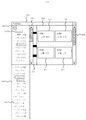
- FIG. 2 is a display example of a conventional management screen when a device is in a specific state in the device management apparatus 100.
- a conventional display example will be described with reference to FIG. 2 in the case where an error has occurred due to an abnormal state occurring in the device as the specific state.
- the management screen 200 includes a group display unit 201, a scroll display unit 204 of the group display unit 201, a device information display unit 205, and a scroll display unit 206 of the device information display unit.
- the group display unit 201 displays the groups from the upper level to the lower level in a tree structure.
- each group from the highest group to the lowest group is referred to as “overall” of the highest group, “block” of the intermediate group, and “group” of the lowest group. .
- the group display unit 201 displays “Group 1” which is a lower group of “Block 1”, “Block 2”, “Block 3” and “Block 1” which are lower groups of “Overall” and “Overall” of the highest level group. “Group B”, “Group C”, “Group D”, “Group E”, “Group F” and “Group G” which are lower groups of "Block 2" are displayed.
- “Group A” is a group that manages device A, device B, device C, and device D.
- Reference numeral 207 denotes device information of the devices A to D managed by the “group A”.
- the management screen creation unit 112 of the device management apparatus 100 changes the display format of “group A”, which is a group that manages the device D in which an error has occurred, and “group A”.
- the display format of “Block 1” and “Overall”, which are the upper groups of the device it is indicated that there is a device in which an error has occurred in the user.
- the group name is surrounded by a frame line.
- Reference numeral 3001 denotes an out-of-range display unit of the group display unit 201 displayed by the user.
- the out-of-range display unit 3001 of the group display unit 201 includes “block 4”, “block 5”, “block 6”, “block 7”, “block 8”, “block 9”, and “block 10” of the intermediate group.
- “Group J”, “Group K”, “Group L”, “Group M”, which is a lower group of “Block 5”, “Group M”, which is a lower group of “Block 7” N "exists.
- the management screen creation unit 112 of the device management apparatus 100 changes the display format of “group J” that manages the device in which an error has occurred in the group display unit 201, and the upper group of “group J”.
- the display format of “Block 5” and “Whole” By changing the display format of “Block 5” and “Whole”, the user is informed that there is a device in which an error has occurred, but “Group J” and “Block 5” are displayed on the group display unit 201. Since the user exists in the out-of-range display unit 3001, the user can only see that “whole” is surrounded by a frame line.
- the device management apparatus 100 may employ a small output device 109 to reduce costs.
- the user can perform a scrolling operation and a tree in order to find out which device has an error on the management screen of the device management apparatus. It is necessary to search for “groups” surrounded by a frame line by performing the unfolding operation, and this causes a problem that the convenience of the user is impaired.
- FIG. 4 is a diagram for explaining a display example of the output device 109 (management screen) of the present embodiment for this purpose.
- Reference numeral 4001 denotes an entire group display unit showing the group display unit 201 and the out-of-range display unit 3001.
- the width in the tree expansion direction of the entire group display portion 4001 and the width in the tree expansion direction of the area to which the scroll bar of the scroll display portion 204 can move are matched as Ht.
- a method for changing the display format of the entire group display unit 4001 will be described.
- the case of coloring will be described as an example of a change in display format.
- the width of the whole group display portion 4001 in the tree expansion direction is Ht, and the number of groups that the user has expanded in the tree (groups with *) is An.
- An is 23.
- the width in the tree expansion direction per group is obtained by Ht / An. That is, the width of the whole group display portion 4001 in the tree expansion direction is divided by the number of groups. Divided areas are assigned in order from the top, and groups of trees are assigned in order from the top. Thereafter, the divided area where the error has occurred in the assigned group is colored.
- the divided areas assigned to “whole”, “block 1”, “group A”, “block 5”, “group J”, and “block 8” in the whole group display portion 4001 are colored.
- the device management apparatus 100 provides a management screen 200 for classifying and managing a plurality of devices into groups, and the amount that fits in a predetermined display area of the management screen 200 in the group.
- Group display unit 201 for displaying the group of the group, and group entire display for displaying the entire group information in the order of the groups displayed on the group display unit 201 and within the predetermined display area of the management screen 200 Part 4001.
- the form of the position of the entire group display unit 4001 corresponding to the group A to which the device D belongs changes corresponding to the predetermined state such as an error.
- the predetermined state such as an error.
- it can mean a warning by coloring it red.
- the groups referred to here may include all of the lowest group from the highest group as described above, or only the “group A” that is the lowest group may be colored.
- the form of the position of the entire group display unit 4001 corresponding to the group A to which the device D belongs changes corresponding to the predetermined state such as an error
- the form of the position of the group display unit 201 corresponding to the group A to which the device D belongs changes.
- the group A is surrounded by a frame line.
- the group A may be colored, the characters become darker, or blinked.
- the display area of the entire group display unit 4001 is divided into more than the number of groups, and information on the entire group is displayed in the divided display area in the order of the groups displayed on the group display unit 201 and the management screen 200. Displayed within a predetermined display area.
- the group here may include all of the lowest group from the highest group as described above, or may include only “Group A” which is the lowest group.
- the group display unit 201 displays a group and a higher group within the predetermined display area of the management screen 200 among the group and the higher group. Then, the display area of the entire group display unit 4001 is divided into more than the total number of the group and the upper group, and the group and upper group information in the divided display area is displayed on the group display unit 201. They are displayed in order of the upper group and within a predetermined display area of the management screen 200.
- FIG. 5 is a display example of the management screen when the scroll display unit 204 and the group whole display unit 4001 of FIG. In this way, the entire group display unit 4001 may be displayed so as to overlap with other screen components. By displaying the entire group display unit 4001 overlaid with other screen components, particularly the scroll display unit 204, it is possible to reduce the user's line-of-sight movement.
- FIG. 6 is a display example of the management screen when the upper end of the third colored portion from the top of FIG. 4 is aligned with the upper end of the scroll bar.
- the scroll display unit 204 that can display all groups on the group display unit 201 by the user's operation of the scroll bar is provided, and the scroll display unit 201 is provided at a position corresponding to the entire group display unit 4001.
- the group display unit 201 displays the predetermined group in the display area when the scroll bar is at a position corresponding to the predetermined group of the entire group display unit 4001.
- 2 to 6 are display examples of the management screen, and do not limit the display format changing method, the tree structure, the number of devices, and the device status shown to the user.
- the user can grasp at a glance where in the tree a device in a specific state such as an error exists without scrolling and expanding the tree. Furthermore, the position of the scroll bar with respect to the entire group display portion 4001 can be associated with the position of the display group with respect to the entire tree, and the convenience of the device management apparatus can be improved.
- FIG. 7 shows a management screen in which all the trees in FIG. 4 are expanded. Further, in this embodiment, the width of the whole group display unit 4001 in FIG. 7 in the tree expansion direction is matched with the width of the group display unit 201 in the tree expansion direction.
- a method for changing the display format of the entire group display unit 4001 will be described.
- the case of coloring will be described as an example of a change in display format.
- the specific state will be described as an error.
- the width of the whole group display portion 4001 in the tree expansion direction is Hv
- the lowest group number (group with *) in the tree structure is Bn.
- the lowest group here corresponds to a “group” such as group A or group B in the first embodiment, and Bn is constant regardless of the expanded state of the tree.
- Bn is 18.
- the width in the tree expansion direction per group is obtained by Hv / Bn. That is, the width of the whole group display portion 4001 in the tree expansion direction is divided into 18 parts. The divided areas are assigned in order from the top, and the lowest group of the tree structure is assigned from the top. Thereafter, the divided area where the error has occurred in the assigned lowest group is colored. In the case of FIG. 7, the divided areas assigned to “Group D”, “Group J”, and “Group P” in the entire group display portion 4001 are colored.
- FIG. 8 shows a display delimiter 801 for each number of groups that can be displayed on the group display unit 201 from the top of the entire group display unit 4001 of FIG.
- the division method described in the present embodiment divides the entire group display unit 4001 by the number of the lowest groups regardless of the expanded state of the tree, and therefore the group position relative to the group display unit 201 and the group relative to the scroll bar. In some cases, the positions of the divided areas of the entire display unit 4001 do not match.
- the divided area can be enlarged by dividing the entire group display portion 4001 by the number of the lowest groups. Further, by enlarging the divided area and changing the display format of the entire group display unit 4001 using the display dividing line 801 and the display frame line 901, the entire group display unit 4001 can be viewed, and the device management apparatus 100 convenience can be improved.
- Example 3 of the present invention will be described.
- the division method of the entire group display unit 4001 has been described in the first and second embodiments.
- the number of divisions may be less than the minimum display unit of the output device.
- the output device 109 is a liquid crystal display, and Ht or Hv is 1000 pixels.
- Ht / An or Hv / Bn size of the divided area
- This problem can be solved by correcting An or Bn to a predetermined value when the size of the divided area is below a certain value.
- An or Bn is corrected to 50 when the size of the divided area is less than 10 pixels.
- the correction value is stored in the storage device 102.
- Ht or Hv is 1000 and An or Bn is 200
- Ht / An or Hv / Bn is 5 and less than 10. Therefore, An or Bn is corrected to 50, and Ht / An or Hv / Bn is recalculated.
- Ht / An or Hv / Bn is 20
- the entire tree display area 4001 is divided into 50 correction values, and the size of the divided area is 20 pixels. If Ht / An or Hv / Bn is not divisible, the remaining pixels are added to the divided area one pixel at a time to adjust the size of the divided area.
- the number of groups is divided by 50 which is a correction value. As a result of the division, it is understood that four groups may be assigned to one divided area. If the number of groups is not divisible by the correction value, the number of remaining groups is added to the divided areas one by one to adjust the number of groups assigned to one divided area.
- FIG. 14 is a display example of the management screen in a state where “block 8” of FIG. 7 is folded.
- the device information display unit 205 displays the device information 207 of the devices A to D managed by the “group A”.
- the processing unit 101 detects a user operation from the input device 108 via the input unit 104 and controls the management screen generation unit 112.
- a screen (screen shown in FIG. 10) in which the selected group of the tree is changed from “group A” to “group D” is created.
- the processing unit 101 outputs the created management screen to the output device 109 via the output unit 105.
- the device information display unit 205 displays the device information 1001 of the devices E to H managed by the “group D”.
- the processing unit 101 detects a user operation from the input device 108 via the input unit 104 and controls the management screen generation unit 112 to control the tree.
- a screen (screen shown in FIG. 11) in which the selected group is changed from “Group A” to “Group J” is created.
- the processing unit 101 outputs the created management screen to the output device 109 via the output unit 105.
- the device information display unit 205 displays the device information 1101 of the devices I to L managed by the “group J”.
- the processing unit 101 detects a user operation from the input device 108 via the input unit 104 and controls the management screen generation unit 112. Then, a screen (screen shown in FIG. 12) in which the selected group of the tree is changed from “Group A” to “Block 8” is created. The processing unit 101 outputs the created management screen to the output device 109 via the output unit 105. As a result, the device information display unit 205 displays the device information 1201 of the devices M to P managed by the “block 8”.
- the user can select a group that manages devices in a specific state in one operation without scrolling and expanding the tree while maintaining the expanded state of the tree. And the convenience of the device management apparatus can be improved.
- FIG. 14 is a display example of the management screen in a state where “block 8” of FIG. 7 is folded.
- the device information display unit 205 displays the device information 207 of the devices A to D managed by the “group A”.
- the processing unit 101 detects a user operation from the input device 108 via the input unit 104 and controls the management screen generation unit 112. Change the selected object in the tree.
- a screen (screen shown in FIG. 13) is created by expanding “Block 8” and “Overall”, which are upper objects of “Group P”, and changing from “Group A” to “Group P”.
- the processing unit 101 outputs the created management screen to the output device 109 via the output unit 105.
- the device information display unit 205 displays the device information 1401 of the devices O and P managed by the “group P”.
- 13 and 14 are display examples of the management screen, and do not limit the display format changing method, the tree structure, the number of devices, and the device status shown to the user.
- the user can select the lowest object that manages the device in a specific state in one operation without scrolling and expanding the tree.
- the convenience of the apparatus can be improved.
- FIG. 18 is a display example of a management screen in which the device managed by “Block 8” in FIG. 14 is not in a specific state.
- the specific state will be described as an error.
- the device information display unit 205 displays the device information 207 of the devices A to D managed by the “group A”.
- the processing unit 101 controls the management screen creation unit 112 to expand “block 8” and display a screen (screen shown in FIG. 7) in which the display formats of “block 8” and “group P” are changed. create.
- the processing unit 101 outputs the created management screen to the output device 109 via the output unit 105.
- “block 8” and “group P” are surrounded by a frame line as an example of a change in display format.
- FIG. 15 The operation that makes it easy to find a device in a specific state when scrolling will be described with reference to FIGS.
- “Group J” in which managed devices are in a specific state is displayed at the top of the tree.
- the specific state is described as an error. From this state, it is assumed that the scroll bar is lowered to a state shown in FIG. At this time, stop scrolling the tree. Further assume that it is lowered below the scroll bar and the state shown in FIG. Here, the scrolling of the tree is resumed.
- scrolling is temporarily stopped in a group that manages devices in a specific state, and it is possible to indicate to the user that a device in a specific state exists, thereby improving the convenience of the device management apparatus. To do.
- Patent Document 1 it is not considered to present to the user that a device in a specific state exists in a display method other than the tree structure. For this reason, when a user searches for a device in a specific state, it is necessary to search for a device having a specific state from the devices displayed in the tree structure and expand the tree structure one by one. In particular, in the case of a tree structure with a deep hierarchy, the operation for expanding the tree increases, which impairs the convenience for the user. In view of this, it is an object of the present embodiment to provide a device management apparatus that allows a user to easily recognize that there is a device in a specific state in a deep tree structure. First, an example of the operation of the device management apparatus 100 will be described with reference to FIGS.
- FIG. 19 shows an example of a configuration diagram of the device management apparatus 100.
- a processing unit 101 that executes various processes for managing devices, a storage device 102 for storing the latest device information 115 and previous device information 116, and a communication path 114.
- a communication unit 103 for transmitting / receiving data to / from each device, an input unit 104 for inputting user operations from the input device 108, and an output unit 105 for outputting video and sound to the output device 109.
- Examples of the storage device 102 include a memory and a hard disk.
- Examples of the input device 108 include a keyboard and a mouse.
- Examples of the output device 109 include a display and a speaker.
- the input device 108 and the output device 109 may be built in the device management apparatus 100.
- Examples of the communication path 114 include Ethernet (registered trademark) and RS-232C.
- the processing unit 101 collects device information of the device A 106 and the device B 107, stores the latest device information 115 in the storage unit 102, stores the latest device information 115 and the previous device information 116.
- FIG. 19 is an example of a configuration diagram of the device management apparatus, and does not limit the configuration of the device, the number of devices, and the connection form of the devices.
- FIG. 20 is a management flowchart of the device management apparatus 100 of FIG. Step 2001:
- the device information collection unit 110 collects the latest device information 115 of the devices A 106 and B 107 via the communication unit 103 and stores them in the storage device 102.
- Step 2002 The device information monitoring unit 111 compares the previous device information 116 with the latest device information 115 and monitors whether there is a change in the device information.
- Step 2003 If there is a change, proceed to Step 2004. If there is no change, the process proceeds to step 205.
- Step 2004 The device information monitoring unit 111 requests the management screen creation unit 112 to create and output a management screen.
- the management screen creation unit 112 creates a management screen using the latest device information 115 stored in the storage device 102 and outputs the management screen to the output device 109 via the output unit 105.
- Step 2005 The device control unit 113 receives user operation information from the input unit 104.
- Step 2006 If there is an operation to control the device, the process proceeds to Step 2007. If there is a screen operation, the process proceeds to step 2008. If there is no operation, the process returns to step 2001 to continue device management.
- Step 2008 The management screen creation unit 112 updates the management screen in accordance with a user operation input from the input device 108 via the input unit 104 and outputs the management screen to the output device 109 via the output unit 105.
- the process returns to step 2001 to continue device management.
- steps 2001 to 2004 in the flowchart may be processed after steps 2005 to 2008. Also, while making each process independent and always performing steps 2001 to 2004, when there is a user operation, the input unit 104 notifies the processing unit 101 of the user operation, and when the processing unit 101 receives the notification, The processing in steps 2001 to 2004 may be temporarily stopped, and steps 2005 to 2008 may be processed.
- FIG. 21 is an example of a management screen of the device management apparatus 100 of FIG.
- the management screen 300 includes a tree display unit 301 (first display unit), a scroll bar 304 of the tree display unit 301 (first display unit), a device information display unit 305 (second display unit), and a device information display unit 305 (first display unit). 2 display units) scroll bar 306.
- a tree display portion 301 (first display portion) 302 indicates a state where the tree is expanded, and 303 indicates a state where the tree is collapsed.
- “A group” is selected.
- Reference numeral 307 displays information on each device.
- the states of the devices A to D are displayed.
- the output device 109 may be external or may be built in the device management apparatus 100.
- the tree structure of hundreds to thousands of air conditioners cannot be displayed on the tree display unit 301 (first display unit) at a time, and the user can display the tree display unit 301 (first display unit).
- the tree structure of hundreds to thousands of air conditioners can be confirmed by operating the expansion and folding of the tree of one display unit) or by operating the scroll bar 304.
- the plurality of devices having the tree structure of this embodiment are classified into a plurality of groups. For example, as shown in FIG. 21, the devices A to G are classified into the A group. Although not shown, a plurality of other devices are classified into the B group or the C group. If the user selects the + B group and the + C group in FIG. 21, the classified devices are displayed in a tree structure. Can be expanded and confirmed. If the -A group is selected, the expanded tree structure can be closed.
- each of the A group, the B group, and the C group belongs to the entire higher group.
- the whole is the highest level group, but other groups may exist at the same upper level as this whole.
- the entire building is the top group
- each floor is the first subgroup
- information indicating the location of the room, east side, etc. on each floor is 2 subgroups
- each air conditioner may belong to the second subgroup which is the lowest group.
- the air conditioner belonging to the group B shown in FIG. 21 is in the specific state described above, for example, the display color of the B group in FIG. By highlighting, the user can know that any of the air conditioners belonging to the group B has entered a specific state.
- the group H is displayed in the tree display portion 301 (first display) even if the display of the group H is highlighted as described above. Since it is not displayed on the display unit), the user cannot grasp this immediately. Thus, by highlighting the entire higher-level group of the group H, the user can recognize that the air conditioner belonging to any of the groups is in a specific state.
- the tree display unit 301 (first Just checking which group of the display unit) the air conditioner in a specific state belongs to takes a great deal of labor. That is, in order to search for this, the user needs to manually display the device information on the device information display unit 305 (second display unit) by operating the scroll bar 304 or selecting the highlighted group. There is a need for further improvements in user convenience.
- FIG. 22 is an example of a configuration diagram of the device management apparatus 400 of the present embodiment.
- the device management apparatus 400 according to the present exemplary embodiment includes a display device selection screen creation unit 401 that creates a specific state device selection unit for selecting a device to be displayed on the management screen in the device management device 100 of FIG.
- a display device selection screen creation unit 401 that creates a specific state device selection unit for selecting a device to be displayed on the management screen in the device management device 100 of FIG.
- specific state information 402 accumulated in the storage device 102 is added.
- FIG. 22 is an example of a configuration diagram of the device management apparatus, and does not limit the configuration of the device, the number of devices, and the connection form of the devices.
- FIG. 23 is a management flowchart of the device management apparatus 400 of this embodiment. Since steps 2001 to 2003 and steps 2005 to 2008 have been described with reference to FIG. 20, description thereof is omitted here.
- step 2004, the operation is changed to step 505.
- Step 503 The device information monitoring unit 111 stores specific state information 402 in the storage device 102.
- Step 504 The device information monitoring unit 111 deletes the specific state information 402 stored in the storage device 102.
- Step 505 The device information monitoring unit 111 requests the management screen creation unit 112 to create and output a management screen.
- the management screen creation unit 112 creates a management screen using the latest device information 115 stored in the storage device 102 and the specific state information 402, and the specific state device selection unit 601 and the specific state Information is output to the output device 109 via the output unit 105.
- Step 506 The display device selection screen creation unit 401 creates a display device selection screen for selecting a device to be displayed, and outputs it to the output device 109 via the output unit 105. At this time, the state to be selected is highlighted using the specific state information 402 stored in the storage device 102.
- Step 507 A display device is set in accordance with a user operation input from the input device 108 via the input unit 104.
- FIG. 24 is an example of a management screen of the device management apparatus 400 of the present embodiment.
- the management screen 600 adds a specific state device selection unit (display device selection button 601) and a notification area 602 (specific state display unit) as a display unit for notifying a specific state to 301 to 307 in FIG. ing.
- a specific state device selection unit display device selection button 601
- a notification area 602 specific state display unit
- it is displayed in the notification area 602 (specific state display unit) that there is a device in which error 1 and error 2 have occurred as an example of a specific state.
- the device in the specific state is displayed by a selection operation.
- the specific state device selection section (display device selection button 601) to be enabled is displayed on the output device 109 (management screen 600).
- the specific state device selection unit (display device selection button 601) uses the scroll bar 304 even when a device in a specific state is not displayed on the tree display unit 301 (first display unit). It is displayed on the management screen 600 without scrolling.
- the specific state device selection unit is highlighted to display the specific state. Even in the case where the device that has become undisplayed is not displayed in the tree display unit 301 (first display unit), the user can immediately recognize that there is a device that has become abnormal such as an error or some specific state. it can.
- a notification area 602 (indicating that there is a device in a specific state) ( Is displayed on the specific state display section).
- This notification area 602 (specific state display unit) is displayed on the management screen 600 without scrolling by the scroll bar 304 even when a device in a specific state is not displayed on the first display unit. Since it is displayed, the user can immediately grasp what specific device is in the specific state immediately.
- FIG. 25 is an example of a display device selection screen that is displayed when the user selects the specific state device selection unit (display device selection button 601).
- the state selection unit includes menus 7001 to 7007 for selecting the state of a device to be displayed, an OK button 7008 for selecting a device to be displayed, and a cancel button 7009 for canceling. That is, on the management screen 600, when the specific state device selection unit (display device selection button 601) is selected, the device status to be displayed is selected from a plurality of states that can be determined by the device information monitoring unit 111.
- a state selection unit (display device selection screen 7000) to be displayed is displayed.
- errors 1 to 7 are shown as examples of a plurality of specific states that can be determined.
- a specific state error 1, error 2 among the plurality of types (error 1 to error 7) is highlighted.
- the search method of the device to be displayed may be AND search, OR search, or NOT search. Alternatively, the search methods may be combined. In this embodiment, it is assumed that error 1 and error 2 have occurred, and the selection menu for error 1 and error 2 is highlighted with a frame. For highlighting, a method of making the character bold, increasing the font size, changing the character color, or blinking the character may be used.
- FIG. 26 shows an example of a screen when error 1 and error 2 are selected by pressing menu selection buttons 7001 and 7002 and a device to be displayed by OR search is selected. Devices with normal status are hidden, and only devices with error 1 and error 2 are displayed. That is, by selecting a specific state (error 1, error 2) (selecting menus 7001 and 7002), the selected device in the specific state and its state are displayed on the management screen 600.
- a specific state error 1, error 2
- the device in a specific state (error 1, error 2) and its state are displayed as shown in FIG.
- the specific state device selection unit (display device selection button 601) in FIG. 24 performs a selection operation
- the specific state device selection unit (display device selection button 601) in FIG. 25 is not displayed, and FIG.
- a device in a specific state (error 1, error 2) and its state may be displayed immediately.
- the device in such a specific state (error 1, error 2) and the display of the state are displayed on the device information display unit 305 (second display unit).
- a state such as an energy saving operation or a maintenance may be selected as a specific state.
- the specific state is not displayed on the tree display unit 301 (first display unit) by highlighting the specific state device selection unit (display device selection button 601). Even if it exists, it can grasp
- the state selection unit by highlighting a specific state (error 1 and error 2 in FIG. 25), the user can see at a glance which state can be used to display useful information. It is possible to grasp the information immediately and to confirm the information immediately.
- step 506 is changed in the management flowchart of FIG. Step 506:
- the display device selection screen creation unit 401 creates a display device selection screen for selecting a device to be displayed, and outputs it to the output device 109 via the output unit 105.
- a specific state is selected and displayed using the specific state information 402 stored in the storage device 102.
- FIG. 27 is an example of a display device selection screen in which a specific state is selected.
- the user can grasp at a glance which state can be used to display useful information, thereby improving the convenience of the device management apparatus. it can.
- Device management device 101 processing unit 102 storage device 103 communication unit 104 input unit 105 output unit 106 device A 107 Equipment R 108 Input device 109 Output device 110 Device information collection unit 111 Device information monitoring unit 112 Management screen creation unit 113 Device control unit 114 Communication path 115 Device information 201 Group display unit 207 Device information 3001 of devices managed by “Group A” Out-of-range display section 4001 Whole group display section 801 Display separation line 901 Display frame line 1001 Device information 1101 managed by “Group D” Device information 1201 managed by “Group J” “Block 8” Device information 1301 of devices managed by the device Group device information 116 of devices managed by “Group P” Previous device information 300 Management screen 301 Tree display portion (first display portion) 302 Tree expanded state 303 Tree collapsed state 304 Scroll bar 305 of the tree display unit (first display unit) Device information display unit (second display unit) 306 Scroll bar 307 of device information display unit (second display unit) 307 Information of each device 400 Device management device 401 Display device selection screen creation unit 402 Specific state information 600
Landscapes
- Engineering & Computer Science (AREA)
- Theoretical Computer Science (AREA)
- General Engineering & Computer Science (AREA)
- Human Computer Interaction (AREA)
- Physics & Mathematics (AREA)
- General Physics & Mathematics (AREA)
- Software Systems (AREA)
- User Interface Of Digital Computer (AREA)
- Air Conditioning Control Device (AREA)
- Facsimiles In General (AREA)
- General Factory Administration (AREA)
Abstract
Description
本願は上記課題を解決する手段を複数含んでいるが、その一例を挙げるならば、複数の機器をグループに分類して管理するための管理画面を提供する機器管理装置であって、前記グループのうち、前記管理画面の所定の表示領域に収まる分のグループを表示するグループ表示部と、前記グループの全体の情報が、前記グループ表示部に表示されたグループの順番に、かつ、前記管理画面の所定の表示領域に納まるように表示するグループ全体表示部と、を備え、前記機器が所定の状態となった場合に、該機器が属するグループに対応する前記グループ全体表示部の位置の形態が前記所定の状態に対応して変化することを特徴とする。
上記した以外の課題、構成及び効果は、以下の実施形態の説明により明らかにされる。
図4はこのための本実施例の出力装置109(管理画面)の表示例を説明するための図である。4001は、グループ表示部201と範囲外表示部3001を示すグループ全体表示部である。本実施例では、グループ全体表示部4001のツリー展開方向の幅と、スクロール表示部204のスクロールバーが移動できる領域のツリー展開方向の幅をHtとして一致させている。
なお、図2~6は管理画面の表示例であり、表示形式の変化方法、ツリー構造、機器数、およびユーザに示す機器状態を限定するものではない。
図7は図4のツリーを全て展開した管理画面を示すものである。また、本実施例では、図7のグループ全体表示部4001のツリー展開方向の幅と、グループ表示部201のツリー展開方向の幅を一致させている。
図7、図10~12、14を用いて、グループ全体表示部4001の表示形式を変化させた部分を選択することで、ツリーの選択グループを、分割領域に割り当てたグループに変更する動作例について説明する。本実施例では、表示形式を変化の一例として、着色する場合について説明する。図14は、図7の「ブロック8」を折りたたんでいる状態の管理画面の表示例である。
図13、図14を用いて、図12とは別のツリーの選択グループを変更する動作例を説明する。図14は、図7の「ブロック8」を折りたたんでいる状態の管理画面の表示例である。
まず図19~21を用いて機器管理装置100の動作の一例を説明した後、本発明の機器管理装置400の動作を図22~26を用いて説明する。なお、本実施例における管理対象となる機器の詳細は省略しているが、たとえば、ビルや店舗、あるいは病院や学校等の施設に取付けられる複数の空気調和機を対象とする。このような空気調和機はある施設に対して、多い場合には数百台~数千台が取付けられることがあるため、そのON・OFFの運転制御や、あるいは異常発生の有無の監視等の機器管理を集中的に行うことが必要となる。本実施例の機器管理装置400は、このような場合に用いられ、設置された複数の空気調和機の管理を集中的に行うものである。
図19は、機器管理装置100の構成図の一例を示す。図19の機器管理装置100は、機器を管理するための様々な処理を実行する処理部101、最新の機器情報115と前回の機器情報116を蓄積するための記憶装置102、通信路114を介して各機器とデータを送受信するための通信部103、入力装置108からユーザの操作を入力する入力部104、出力装置109に映像や音を出力する出力部105で構成する。
ステップ2001:機器情報収集部110は、通信部103を介して機器A106と機器B107の最新の機器情報115を収集し、記憶装置102に蓄積する。
ステップ2002:機器情報監視部111は、前回の機器情報116と最新の機器情報115を比較し、機器情報に変化があるか否かを監視する。
ステップ2003:変化がある場合はステップ2004へ進む。変化がない場合はステップ205へ進む。
ステップ2004:機器情報監視部111は、管理画面作成部112へ管理画面の作成と出力を要求する。管理画面作成部112は、記憶装置102に蓄積している最新の機器情報115を用いて管理画面を作成し、出力部105を介して出力装置109へと出力する。
ステップ2005:機器制御部113は、入力部104からユーザの操作情報を受信する。
ステップ2006:機器を制御する操作がある場合はステップ2007へ進む。画面の操作がある場合はステップ2008へ進む。操作がない場合はステップ2001へ戻り、機器の管理を続行する。
ステップ2007:制御部113は、入力部104を介して入力装置108から入力されたユーザの操作に従って制御データを作成し、通信部103を介して機器A106と機器B107を制御する。制御が完了するとステップ2001へ戻り、機器の管理を続行する。
ステップ2008:管理画面作成部112は、入力部104を介して入力装置108から入力されたユーザの操作に従って管理画面を更新し、出力部105を介して出力装置109へと出力する。画面の更新が完了するとステップ2001へ戻り、機器の管理を続行する。
ステップ501:機器情報監視部111は、最新の機器情報115から、機器が特定の状態になっていないか、例えばエラーが発生している機器が存在するかを検索する。
ステップ502:特定の状態になっている機器が存在する場合はステップ503へ進む。存在しない場合はステップ504へ進む。
ステップ503:機器情報監視部111は、特定の状態情報402を記憶装置102に蓄積する。
ステップ504:機器情報監視部111は、記憶装置102に蓄積している特定の状態情報402を削除する。
ステップ505:機器情報監視部111は、管理画面作成部112へ管理画面の作成と出力を要求する。管理画面作成部112は、要求を受けると記憶装置102に蓄積している最新の機器情報115と、特定の状態情報402を用いて管理画面を作成し、特定状態機器選択部601及び特定の状態情報を出力部105を介して出力装置109へと出力する。
ステップ506:表示機器選択画面作成部401は、表示する機器を選択するための表示機器選択画面を作成し、出力部105を介して出力装置109へと出力する。この時、記憶装置102に蓄積している特定の状態情報402を用いて、選択する状態を強調表示する。
ステップ507:入力部104を介して入力装置108から入力されたユーザの操作に従って表示機器を設定する。
ステップ508:管理画面作成部112は、ステップ507の設定に従って管理画面を作成し、出力部105を介して出力装置109へ出力する。画面の更新が完了するとステップ2001へ戻り、機器の管理を続行する。
本実施例では図23の管理フローチャートにおいて、ステップ506の動作を変更する。
ステップ506:表示機器選択画面作成部401は、表示する機器を選択するための表示機器選択画面を作成し、出力部105を介して出力装置109へと出力する。この時、記憶装置102に蓄際している特定の状態情報402を用いて、特定の状態を選択して表示する。
101 処理部
102 記憶装置
103 通信部
104 入力部
105 出力部
106 機器A
107 機器R
108 入力装置
109 出力装置
110 機器情報収集部
111 機器情報監視部
112 管理画面作成部
113 機器制御部
114 通信路
115 機器情報
201 グループ表示部
207 「グループA」が管理している機器の機器情報
3001 範囲外表示部
4001 グループ全体表示部
801 表示区切り線
901 表示枠線
1001 「グループD」が管理している機器の機器情報
1101 「グループJ」が管理している機器の機器情報
1201 「ブロック8」が管理している機器の機器情報
1301 「グループP」が管理している機器の機器情報
116 前回の機器情報
300 管理画面
301 ツリー表示部(第1表示部)
302 ツリー展開状態
303 ツリー折りたたみ状態
304 ツリー表示部(第1表示部)のスクロールバー
305 機器情報表示部(第2表示部)
306 機器情報表示部(第2表示部)のスクロールバー
307 各機器の情報
400 機器管理装置
401 表示機器選択画面作成部
402 特定の状態情報
600 管理画面
601 表示機器選択ボタン(特定状態機器選択部)
602 通知領域
7000 表示機器選択画面(状態選択部)
7001 状態を選択するメニュー
7002 状態を選択するメニュー
7003 状態を選択するメニュー
7004 状態を選択するメニュー
7005 状態を選択するメニュー
7006 状態を選択するメニュー
7007 状態を選択するメニュー
7008 OKボタン
7009 キャンセルボタン
Claims (10)
- 複数の機器をグループに分類して管理するための管理画面を提供する機器管理装置であって、
前記グループのうち、前記管理画面の所定の表示領域に収まる分のグループを表示するグループ表示部と、
前記グループの全体の情報が、前記グループ表示部に表示されたグループの順番に、かつ、前記管理画面の所定の表示領域に納まるように表示するグループ全体表示部と、を備え、
前記機器が所定の状態となった場合に、該機器が属するグループに対応する前記グループ全体表示部の位置の形態が前記所定の状態に対応して変化することを特徴とする機器管理装置。 - 請求項1に記載の機器管理装置において、
前記複数の機器が所定の状態となった場合に、
該機器が属するグループに対応する前記グループ全体表示部の位置の形態が前記所定の状態に対応して変化するとともに、該機器が属するグループに対応する前記グループ表示部の位置の形態が変化することを特徴とする機器管理装置。 - 請求項1に記載の機器管理装置において、
前記グループ全体表示部の表示領域は前記グループの数以上に分割され、この分割された表示領域に前記グループの全体の情報が、前記グループ表示部に表示されたグループの順番に、かつ、前記管理画面の所定の表示領域に納まるように表示されることを特徴とする機器管理装置。 - 請求項1に記載の機器管理装置において、
前記グループはさらに上位グループに分類して管理され、
前記グループ表示部には、前記グループ及び前記上位グループのうち、前記管理画面の所定の表示領域に収まる分のグループ及び上位グループが表示され、
前記グループ全体表示部の表示領域は前記グループ及び前記上位グループを合わせた数以上に分割され、この分割した表示領域に前記グループ及び前記上位グループの全体の情報が、前記グループ表示部に表示されたグループ及び上位グループの順番に、かつ、前記管理画面の所定の表示領域に納まるように表示されることを特徴とする機器管理装置。 - 請求項1に記載の機器管理装置において、
ユーザによるスクロールバーの操作により、前記グループ表示部に全てのグループを表示可能とするスクロール表示部を備え、
該スクロール表示部は、前記グループ全体表示部と対応する位置に設けられるとともに、
前記グループ表示部は、前記スクロールバーが前記グループ全体表示部の所定のグループに対応する位置にあるとき、該所定のグループを表示領域に表示することを特徴とする機器管理装置。 - 複数の機器が複数のグループに分類され、前記複数のグループと前記複数の機器とをツリー構造で表示する第1表示部と、
該第1表示部に前記複数のグループ又は前記複数の機器の全てが表示できない場合に、スクロール動作によって、前記複数のグループ又は前記複数の機器の全てを前記第1表示部に表示可能とするスクロール部と、
前記第1表示部に表示された前記複数のグループが選択されることで、該選択されたグループに属する機器の情報を表示する、あるいは、前記第1表示部に表示された前記複数の機器のうち選択された機器の情報を表示する第2表示部と、を有する管理画面を提供する機器管理装置において、
前記複数の機器の状態を監視する機器情報監視部を備え、
前記管理画面には、
該機器情報監視部により、前記複数の機器の何れかが特定の状態となったと判断した場合に、前記特定の状態となった機器を選択動作により表示可能とする特定状態機器選択部が表示され、
該特定状態機器選択部は、前記特定の状態となった機器が前記第1表示部に表示されていない場合であっても、前記スクロール部によるスクロール動作をすることなく前記管理画面上に表示され、かつ、前記機器情報監視部により前記複数の機器の何れかが特定の状態となったと判断した場合に強調表示されることを特徴とする機器管理装置。 - 請求項1に記載の機器管理装置において、
前記管理画面には、
前記特定状態機器選択部に選択動作があった場合に、前記特定の状態の機器及びその状態が表示されることを特徴とする機器管理装置。 - 請求項1に記載の機器管理装置において、
前記管理画面には、
前記特定状態機器選択部に選択動作があった場合に、前記機器情報監視部によって判断可能な複数種の状態から表示する機器の状態を選択する状態選択部が表示され、
該状態選択部において前記複数種の状態のうち、前記特定の状態が強調表示され、該特定の状態を選択することで該選択された特定の状態の機器及びその状態が表示されることを特徴とする機器管理装置。 - 請求項7又は8に記載の機器管理装置において、
前記特定の状態の機器及びその状態の表示は、前記第2表示部にされることを特徴とする機器管理装置。 - 請求項6~8の何れかに記載の機器管理装置において、
前記管理画面には、
前記機器情報監視部により、前記複数の機器の何れかが特定の状態となったと判断した場合に、前記特定の状態となった機器があることを表示する特定状態表示部が表示され、 該特定状態表示部は、前記特定の状態となった機器が前記第1表示部に表示されていない場合であっても、前記スクロール部によるスクロール動作をすることなく前記管理画面上に表示されることを特徴とする機器管理装置。
Priority Applications (5)
| Application Number | Priority Date | Filing Date | Title |
|---|---|---|---|
| JP2014524698A JP6072794B2 (ja) | 2012-07-12 | 2013-06-12 | 機器管理装置 |
| EP13816956.0A EP2874052A4 (en) | 2012-07-12 | 2013-06-12 | DEVICE FOR MANAGING MACHINES |
| CN201380036418.1A CN104412215B (zh) | 2012-07-12 | 2013-06-12 | 设备管理装置 |
| IN11254DEN2014 IN2014DN11254A (ja) | 2012-07-12 | 2013-06-12 | |
| BR112015000299A BR112015000299A2 (pt) | 2012-07-12 | 2013-06-12 | dispositivo de gerenciamento de máquina |
Applications Claiming Priority (4)
| Application Number | Priority Date | Filing Date | Title |
|---|---|---|---|
| JP2012156081 | 2012-07-12 | ||
| JP2012-156081 | 2012-07-12 | ||
| JP2012-190809 | 2012-08-31 | ||
| JP2012190809 | 2012-08-31 |
Publications (1)
| Publication Number | Publication Date |
|---|---|
| WO2014010362A1 true WO2014010362A1 (ja) | 2014-01-16 |
Family
ID=49915830
Family Applications (1)
| Application Number | Title | Priority Date | Filing Date |
|---|---|---|---|
| PCT/JP2013/066139 WO2014010362A1 (ja) | 2012-07-12 | 2013-06-12 | 機器管理装置 |
Country Status (6)
| Country | Link |
|---|---|
| EP (1) | EP2874052A4 (ja) |
| JP (2) | JP6072794B2 (ja) |
| CN (1) | CN104412215B (ja) |
| BR (1) | BR112015000299A2 (ja) |
| IN (1) | IN2014DN11254A (ja) |
| WO (1) | WO2014010362A1 (ja) |
Cited By (2)
| Publication number | Priority date | Publication date | Assignee | Title |
|---|---|---|---|---|
| JP6147385B1 (ja) * | 2016-03-18 | 2017-06-14 | アンリツ株式会社 | パラメータ設定装置、パラメータ設定方法及び移動端末試験装置 |
| WO2022259677A1 (ja) * | 2021-06-07 | 2022-12-15 | パナソニックIpマネジメント株式会社 | 資産管理支援システム、資産管理システム、及び資産管理支援方法 |
Families Citing this family (3)
| Publication number | Priority date | Publication date | Assignee | Title |
|---|---|---|---|---|
| WO2018079031A1 (ja) | 2016-10-31 | 2018-05-03 | 日本電気株式会社 | 画像処理装置、画像処理方法、顔認証システム、プログラム及び記録媒体 |
| JP7334511B2 (ja) * | 2019-07-05 | 2023-08-29 | オムロン株式会社 | 監視装置、監視方法、監視プログラム、および、記録媒体 |
| CN113055235A (zh) * | 2021-03-30 | 2021-06-29 | 合安科技技术有限公司 | 一种基于树的设备选择方法、系统及相关设备 |
Citations (4)
| Publication number | Priority date | Publication date | Assignee | Title |
|---|---|---|---|---|
| JPH04337798A (ja) * | 1991-04-16 | 1992-11-25 | Internatl Business Mach Corp <Ibm> | ディスプレイ・ウィンドウを備えたデータ処理システム |
| JP2002222471A (ja) * | 2001-01-29 | 2002-08-09 | Nittan Co Ltd | 防災受信機 |
| JP2010009568A (ja) * | 2008-05-29 | 2010-01-14 | Daikin Ind Ltd | 機器管理装置 |
| JP2010186229A (ja) * | 2009-02-10 | 2010-08-26 | Daikin Ind Ltd | 機器管理装置、機器管理プログラムおよび画面提供装置 |
Family Cites Families (7)
| Publication number | Priority date | Publication date | Assignee | Title |
|---|---|---|---|---|
| JP3240162B2 (ja) * | 1991-08-23 | 2001-12-17 | 株式会社日立製作所 | プロセス制御システムにおける画面表示方法およびマンマシンインタフェース装置 |
| JP2000047778A (ja) * | 1998-07-30 | 2000-02-18 | Yamatake Corp | 情報視覚化方法 |
| US6430574B1 (en) * | 1999-07-22 | 2002-08-06 | At&T Corp. | Method and apparatus for displaying and header scrolling a hierarchical data structure |
| JP2009038624A (ja) * | 2007-08-02 | 2009-02-19 | Panasonic Corp | 情報収集システム |
| JP5527521B2 (ja) * | 2007-12-06 | 2014-06-18 | 日本電気株式会社 | 階層構造表示装置、階層構造表示方法および階層構造表示制御プログラム |
| BRPI0912318A2 (pt) * | 2008-05-22 | 2015-10-13 | Daikin Ind Ltd | aparelho de gerenciamento de equipamento |
| JP5140538B2 (ja) * | 2008-09-30 | 2013-02-06 | 任天堂株式会社 | 起動制御プログラム、起動制御装置、起動制御システム、及び、起動制御方法 |
-
2013
- 2013-06-12 BR BR112015000299A patent/BR112015000299A2/pt not_active Application Discontinuation
- 2013-06-12 IN IN11254DEN2014 patent/IN2014DN11254A/en unknown
- 2013-06-12 EP EP13816956.0A patent/EP2874052A4/en not_active Withdrawn
- 2013-06-12 CN CN201380036418.1A patent/CN104412215B/zh active Active
- 2013-06-12 WO PCT/JP2013/066139 patent/WO2014010362A1/ja active Application Filing
- 2013-06-12 JP JP2014524698A patent/JP6072794B2/ja active Active
-
2016
- 2016-09-09 JP JP2016176071A patent/JP6158410B2/ja active Active
Patent Citations (5)
| Publication number | Priority date | Publication date | Assignee | Title |
|---|---|---|---|---|
| JPH04337798A (ja) * | 1991-04-16 | 1992-11-25 | Internatl Business Mach Corp <Ibm> | ディスプレイ・ウィンドウを備えたデータ処理システム |
| JP2002222471A (ja) * | 2001-01-29 | 2002-08-09 | Nittan Co Ltd | 防災受信機 |
| JP2010009568A (ja) * | 2008-05-29 | 2010-01-14 | Daikin Ind Ltd | 機器管理装置 |
| JP4466776B2 (ja) | 2008-05-29 | 2010-05-26 | ダイキン工業株式会社 | 機器管理装置 |
| JP2010186229A (ja) * | 2009-02-10 | 2010-08-26 | Daikin Ind Ltd | 機器管理装置、機器管理プログラムおよび画面提供装置 |
Non-Patent Citations (1)
| Title |
|---|
| See also references of EP2874052A4 |
Cited By (3)
| Publication number | Priority date | Publication date | Assignee | Title |
|---|---|---|---|---|
| JP6147385B1 (ja) * | 2016-03-18 | 2017-06-14 | アンリツ株式会社 | パラメータ設定装置、パラメータ設定方法及び移動端末試験装置 |
| JP2017168019A (ja) * | 2016-03-18 | 2017-09-21 | アンリツ株式会社 | パラメータ設定装置、パラメータ設定方法及び移動端末試験装置 |
| WO2022259677A1 (ja) * | 2021-06-07 | 2022-12-15 | パナソニックIpマネジメント株式会社 | 資産管理支援システム、資産管理システム、及び資産管理支援方法 |
Also Published As
| Publication number | Publication date |
|---|---|
| JPWO2014010362A1 (ja) | 2016-06-20 |
| JP6158410B2 (ja) | 2017-07-05 |
| JP2016212921A (ja) | 2016-12-15 |
| EP2874052A4 (en) | 2016-08-10 |
| CN104412215A (zh) | 2015-03-11 |
| CN104412215B (zh) | 2018-01-09 |
| EP2874052A1 (en) | 2015-05-20 |
| IN2014DN11254A (ja) | 2015-10-09 |
| BR112015000299A2 (pt) | 2017-06-27 |
| JP6072794B2 (ja) | 2017-02-01 |
Similar Documents
| Publication | Publication Date | Title |
|---|---|---|
| JP6158410B2 (ja) | 機器管理装置 | |
| CN110034947B (zh) | 远程设备管理界面 | |
| JP4921338B2 (ja) | プラント監視制御システム | |
| US10268347B2 (en) | Display area wide control area | |
| US20160245542A1 (en) | Air conditioner managing console and air-conditioning system | |
| JP2008170047A (ja) | 空調機システム、空調機システムの制御方法および集中管理装置 | |
| JP4870034B2 (ja) | プラント監視制御装置 | |
| JP2015158550A (ja) | マルチディスプレイ用表示制御装置およびマルチディスプレイシステム | |
| JP2010231291A (ja) | プラント監視制御装置 | |
| US20200064992A1 (en) | Display screen generation apparatus, factory automation system, and display screen generation method | |
| JP4484808B2 (ja) | 監視制御画面表示装置 | |
| KR102076754B1 (ko) | 제어로직 진단 시스템 및 그의 진단 방법 | |
| JP7110878B2 (ja) | 空気調和機用コントローラ | |
| JP2011248624A (ja) | 監視制御システム及びその監視画面表示方法 | |
| JP2017151129A (ja) | マルチディスプレイシステム | |
| JP7205990B2 (ja) | 表示制御装置および表示制御方法 | |
| JP2009169225A (ja) | トレンドグラフ表示方法 | |
| JP4646633B2 (ja) | 大画面表示装置の協調作業システム及び表示領域の管理方法 | |
| JP5889166B2 (ja) | プラント監視制御システム | |
| JP5489781B2 (ja) | 監視制御システム | |
| JP6734985B1 (ja) | 業務管理システム及び業務管理方法 | |
| JP6218680B2 (ja) | ネットワーク解析支援装置、ネットワーク解析支援方法、および、プログラム | |
| JPH07122920B2 (ja) | 故障監視装置 | |
| JP6637733B2 (ja) | 空調機管理用画面生成装置、およびこれを利用する空調管理装置、空調機管理用画面生成方法 | |
| JPH0844424A (ja) | プラント監視装置 |
Legal Events
| Date | Code | Title | Description |
|---|---|---|---|
| 121 | Ep: the epo has been informed by wipo that ep was designated in this application |
Ref document number: 13816956 Country of ref document: EP Kind code of ref document: A1 |
|
| ENP | Entry into the national phase |
Ref document number: 2014524698 Country of ref document: JP Kind code of ref document: A |
|
| WWE | Wipo information: entry into national phase |
Ref document number: 2013816956 Country of ref document: EP |
|
| NENP | Non-entry into the national phase |
Ref country code: DE |
|
| REG | Reference to national code |
Ref country code: BR Ref legal event code: B01A Ref document number: 112015000299 Country of ref document: BR |
|
| ENP | Entry into the national phase |
Ref document number: 112015000299 Country of ref document: BR Kind code of ref document: A2 Effective date: 20150107 |