WO2014010339A1 - トンネル掘削方法 - Google Patents
トンネル掘削方法 Download PDFInfo
- Publication number
- WO2014010339A1 WO2014010339A1 PCT/JP2013/065553 JP2013065553W WO2014010339A1 WO 2014010339 A1 WO2014010339 A1 WO 2014010339A1 JP 2013065553 W JP2013065553 W JP 2013065553W WO 2014010339 A1 WO2014010339 A1 WO 2014010339A1
- Authority
- WO
- WIPO (PCT)
- Prior art keywords
- tunnel
- excavation
- excavator
- reaction force
- side wall
- Prior art date
- Legal status (The legal status is an assumption and is not a legal conclusion. Google has not performed a legal analysis and makes no representation as to the accuracy of the status listed.)
- Ceased
Links
Images








Classifications
-
- E—FIXED CONSTRUCTIONS
- E21—EARTH OR ROCK DRILLING; MINING
- E21D—SHAFTS; TUNNELS; GALLERIES; LARGE UNDERGROUND CHAMBERS
- E21D9/00—Tunnels or galleries, with or without linings; Methods or apparatus for making thereof; Layout of tunnels or galleries
- E21D9/10—Making by using boring or cutting machines
- E21D9/1006—Making by using boring or cutting machines with rotary cutting tools
-
- E—FIXED CONSTRUCTIONS
- E21—EARTH OR ROCK DRILLING; MINING
- E21D—SHAFTS; TUNNELS; GALLERIES; LARGE UNDERGROUND CHAMBERS
- E21D9/00—Tunnels or galleries, with or without linings; Methods or apparatus for making thereof; Layout of tunnels or galleries
- E21D9/008—Driving transverse tunnels starting from existing tunnels
-
- E—FIXED CONSTRUCTIONS
- E21—EARTH OR ROCK DRILLING; MINING
- E21D—SHAFTS; TUNNELS; GALLERIES; LARGE UNDERGROUND CHAMBERS
- E21D9/00—Tunnels or galleries, with or without linings; Methods or apparatus for making thereof; Layout of tunnels or galleries
- E21D9/01—Methods or apparatus for enlarging or restoring the cross-section of tunnels, e.g. by restoring the floor to its original level
-
- E—FIXED CONSTRUCTIONS
- E21—EARTH OR ROCK DRILLING; MINING
- E21D—SHAFTS; TUNNELS; GALLERIES; LARGE UNDERGROUND CHAMBERS
- E21D9/00—Tunnels or galleries, with or without linings; Methods or apparatus for making thereof; Layout of tunnels or galleries
- E21D9/10—Making by using boring or cutting machines
- E21D9/1093—Devices for supporting, advancing or orientating the machine or the tool-carrier
-
- E—FIXED CONSTRUCTIONS
- E21—EARTH OR ROCK DRILLING; MINING
- E21D—SHAFTS; TUNNELS; GALLERIES; LARGE UNDERGROUND CHAMBERS
- E21D9/00—Tunnels or galleries, with or without linings; Methods or apparatus for making thereof; Layout of tunnels or galleries
- E21D9/10—Making by using boring or cutting machines
- E21D9/11—Making by using boring or cutting machines with a rotary drilling-head cutting simultaneously the whole cross-section, i.e. full-face machines
- E21D9/112—Making by using boring or cutting machines with a rotary drilling-head cutting simultaneously the whole cross-section, i.e. full-face machines by means of one single rotary head or of concentric rotary heads
-
- E—FIXED CONSTRUCTIONS
- E21—EARTH OR ROCK DRILLING; MINING
- E21D—SHAFTS; TUNNELS; GALLERIES; LARGE UNDERGROUND CHAMBERS
- E21D9/00—Tunnels or galleries, with or without linings; Methods or apparatus for making thereof; Layout of tunnels or galleries
- E21D9/14—Layout of tunnels or galleries; Constructional features of tunnels or galleries, not otherwise provided for, e.g. portals, day-light attenuation at tunnel openings
-
- E—FIXED CONSTRUCTIONS
- E21—EARTH OR ROCK DRILLING; MINING
- E21F—SAFETY DEVICES, TRANSPORT, FILLING-UP, RESCUE, VENTILATION, OR DRAINING IN OR OF MINES OR TUNNELS
- E21F17/00—Methods or devices for use in mines or tunnels, not covered elsewhere
Definitions
- the present invention relates to a tunnel excavation method for excavating tunnels that intersect each other.
- Patent Document 1 discloses a method for constructing a shield tunnel branch / joint including a step of excavating a tunnel branch using such an excavator.
- the conventional method for constructing a branch / junction of a shield tunnel has the following problems. That is, in the tunnel excavation method disclosed in the above publication, when excavating the branch / joint section, the excavator is moved back and forth many times to excavate the branch / joint section, which is very troublesome. There is a problem that construction efficiency is low.
- the subject of this invention is providing the tunnel excavation method which can excavate the branch part of a tunnel efficiently.
- a tunnel excavation method is a tunnel excavation method for excavating a tunnel using an excavator that performs excavation by rotating a cutter head while pressing a gripper against a side wall.
- a process and a second excavation process In the first excavation process, three or more first tunnels that are substantially parallel to each other are excavated.
- the second excavation step the second tunnel that intersects the first tunnel is excavated, and an alternative surface that becomes a part of the side wall of the second tunnel is formed on the first tunnel side at the intersection of the first and second tunnels.
- a tunnel excavation auxiliary device equipped with a reaction force receiving part is arranged.
- the second tunnel intersecting the first tunnel is excavated.
- the second tunnel intersecting the first tunnel is excavated, so that only the substantially straight excavation can be performed.
- the second tunnel can be excavated as a branch. Therefore, compared with the conventional tunnel excavation method, since a linear excavation part becomes almost, the efficiency of excavation work can be improved.
- a tunnel excavation assisting device having a reaction force receiving portion that forms an alternative surface that becomes a part of the side wall of the second tunnel is installed on the existing first tunnel side.
- the place without the side wall as the 2nd tunnel which arises in the part which crosses with the existing 1st tunnel can be block
- the tunnel excavation method according to the second invention is the tunnel excavation method according to the first invention, and after excavating the intersection of the first and second tunnels in the second excavation step, A moving step of moving to the intersection of the first and second tunnels is further provided.
- the tunnel excavation auxiliary device is moved to each intersection.
- the tunnel excavation auxiliary device can be efficiently moved to the intersections, and the excavation of the intersections can be performed efficiently.
- a tunnel excavation method is the tunnel excavation method according to the first or second invention, and in the first excavation step, a part of the side wall outside the bent portion in the portion where the first tunnel is bent.
- a tunnel excavation assisting device having a corner reaction force receiving portion that forms an alternative surface is arranged.
- a tunnel excavation auxiliary device provided with a reaction force receiving portion that receives the reaction force of the excavator is installed at an outer position where the first tunnel is bent.
- a tunnel excavation method is a tunnel excavation method for excavating a tunnel using an excavator that performs excavation by rotating a cutter head in a state where a gripper is pressed against a side wall.
- the first excavation process the first tunnel is excavated. Drilling of the second tunnel that intersects the first tunnel is scheduled.
- the preparation step prepares an alternative surface that becomes a part of the side wall of the second tunnel at the intersection of the first tunnel and the second tunnel.
- the alternative surface is relocated to a portion where the first tunnel is expected to intersect, and is used as a part of the side wall of the second tunnel.
- the second excavation step is a step of excavating the second tunnel, and excavation is performed by pressing a gripper against an alternative surface at a planned intersection.
- a tunnel excavation method according to a fifth invention is the tunnel excavation method according to the fourth invention, wherein the first tunnel includes at least three substantially parallel portions.
- the first tunnel includes at least three substantially parallel portions.
- the construction efficiency can be improved as the excavation at the intersection increases as compared with the conventional excavation method.
- a tunnel excavation method is the tunnel excavation method according to the fifth invention, wherein substantially parallel portions of the first tunnel are connected by a curved portion, thereby forming a continuous tunnel.
- a tunnel excavation method according to a seventh invention is the tunnel excavation method according to the fourth invention, wherein the second tunnel includes at least three substantially parallel portions.
- the second tunnel includes at least three substantially parallel portions.
- the construction efficiency can be improved as the excavation at the intersection increases as compared with the conventional excavation method.
- a tunnel excavation method is the tunnel excavation method according to the seventh invention, wherein the substantially parallel portions of the second tunnel are connected by a curved portion, thereby forming a continuous tunnel.
- the second tunnel excavation can be performed only by the advancement of the excavator, and further, the excavation of the plurality of intersecting portions can reduce the movement of the alternative surface, so that the construction efficiency can be improved.
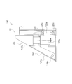
- the side view which shows the structure of the excavator used in the tunnel excavation method using the tunnel excavation auxiliary device which concerns on one Embodiment of this invention.
- Sectional drawing which shows the state which performs tunnel excavation using the excavator of FIG. 1 and the tunnel excavation auxiliary device of this embodiment.
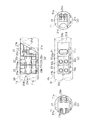
- (A) is a top view which shows the state installed in the tunnel of the tunnel excavation auxiliary apparatus of FIG.
- B) is sectional drawing of the rear end side.
- (C) is the side view.
- (D) is the front sectional view.
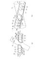
- (A) (b) is the top view and perspective view which show the state which installed the tunnel excavation auxiliary device of FIG. 2 in the tunnel.
- (A) is a top view which shows the state which can move within the tunnel of the tunnel excavation auxiliary device of FIG.
- (B) is sectional drawing of the rear end side.
- (C) is the side view.
- (D) is the front sectional view.
- (A), (b) is the top view and perspective view which show the state which enabled the tunnel excavation auxiliary
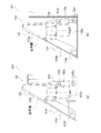
- (A), (b) is a figure which shows the procedure of the tunnel excavation by the tunnel excavation method which concerns on one Embodiment of this invention.
- (A), (b) is a figure which shows the procedure of the tunnel excavation by the tunnel excavation method which concerns on one Embodiment of this invention.
- (A), (b) is a figure which shows the procedure of the tunnel excavation by the tunnel excavation method which concerns on one Embodiment of this invention.
- (A), (b) is a figure which shows the procedure of the tunnel excavation by the tunnel excavation method which concerns on one Embodiment of this invention.
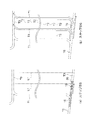
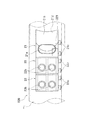
- Sectional drawing which shows the internal structure of the tunnel excavation auxiliary apparatus which concerns on other embodiment of this invention.
- (A), (b) is a figure explaining the mechanism which adjusts the angle of the reaction force receiving part of the tunnel excavation auxiliary device of FIG.
- the side view which shows the structure of the tunnel excavation auxiliary apparatus which concerns on other embodiment of this invention.
- Explanatory drawing which shows the tunnel excavation method which concerns on other embodiment of this invention.
- FIGS. 1 to 10B A tunnel excavation auxiliary apparatus and a tunnel excavation method using the same according to an embodiment of the present invention will be described with reference to FIGS. 1 to 10B.
- the excavator 10 (FIG. 1 etc.) which appears in this embodiment is what is called a gripper TBM and a hard rock TBM among TBM (tunnel boring machine).
- the tunnels excavated by the excavator 10 (first and second tunnels T1, T2) are both tunnels having a substantially circular cross section as shown in FIG. 4B.
- the cross-sectional shape of the tunnel according to the present invention is not limited to a circle, but may be an ellipse, a double circle, a horseshoe or the like.
- the first and second tunnels T1 and T2 are excavated using the excavator 10 shown in FIG.
- the excavator 10 described in the present embodiment is an excavator having a general configuration in which excavation is performed by rotating a cutter head in a state where the excavator 10 is supported rearward by a gripper.
- the excavator 10 is a device that performs excavation work of a tunnel while excavating a rock or the like, and includes a cutter head 11, a gripper 12a, and a thrust jack 13, as shown in FIG.
- the cutter head 11 is disposed on the distal end side of the excavator 10, and rotates around the central axis of the substantially circular tunnel as a rotation center, so that a plurality of disks provided on the distal end side surface.
- the rock 11 is excavated by the cutter 11a.
- the cutter head 11 takes in the bedrock, the rock, etc. which were finely crushed with the disk cutter 11a into the inside from the opening part (not shown) formed in the surface.
- the gripper mounting portion 12 is disposed on the rear side of the excavator 10 and constitutes a rear trunk portion of the excavator 10.
- a gripper 12 a is provided on both sides in the width direction of the gripper mounting portion 12. As shown in FIG. 2, the gripper 12a is pressed against the side wall T2a of the second tunnel T2 during excavation to support the excavator 10 in the second tunnel T2.
- the thrust jack 13 is disposed in the middle of the excavator 10, and constitutes a middle trunk portion of the excavator 10. Further, the thrust jack 13 extends and contracts between the cutter head 11 and the gripper 12a, thereby moving the excavator 10 forward little by little while excavating the second tunnel T2. As shown in FIG. 1, the support portion 14 is disposed between the cutter head 11 and the thrust jack 13 and constitutes a front trunk portion of the excavator 10 together with the cutter head 11. Further, the support portion 14 supports the front trunk portion of the excavator 10 in the second tunnel T2.
- the excavator 10 is configured so that the gripper 12a is pressed against the side wall T2a of the second tunnel T2 and is held so as not to move in the second tunnel T2 in the above-described configuration. While rotating 11, the thrust jack 13 is extended and the cutter head 11 is pressed against the face to excavate the bedrock and advance. At this time, the excavator 10 transports the finely crushed rock or the like backward using a belt conveyor or the like (not shown). In this way, the second tunnel T2 (see FIG. 2) can be dug.
- the tunnel excavation auxiliary device 20 performs first and second operations when excavating a second tunnel T2 that intersects the existing first tunnel T1. It is installed on the first tunnel T1 side at the intersection of the tunnels T1 and T2. Two tunnel excavation assisting devices 20 are installed in the first tunnel T1 so as to sandwich the second tunnel T2 from both sides at the intersection of the first and second tunnels T1 and T2.
- the tunnel excavation assisting device 20 when excavating the second tunnel T2, the tunnel excavation assisting device 20 replaces the side wall T2a in a portion without the side wall T2a formed at the intersection with the second tunnel T2 in the first tunnel T1.
- An alternative surface to be used is formed. More specifically, as shown in FIG. 2, the tunnel excavation auxiliary device 20 includes a reaction force receiving portion 21 and first and second divided portions 22 and 23.
- reaction force receiving portion 21 is provided on the existing first tunnel T1 side in order to form an alternative surface in a portion where the side wall of the second tunnel T2 generated at the intersection of the first and second tunnels T1 and T2 is not present. Yes. As shown in FIG. 2, the reaction force receiving portion 21 is disposed at the head of the tunnel excavation auxiliary device 20, and includes a jack 21a, a reaction force receiving surface (alternative surface) 21b, a traveling wheel (traveling portion) 21c, And a cut portion 21d.
- the jack 21a receives a reaction force as an alternative surface of the side wall T2a at a portion where the side wall T2a of the second tunnel T2 formed at the intersection of the first and second tunnels T1 and T2 is not provided.
- the surface 21b it is provided so as to be able to advance and retreat with respect to the side wall T1a of the first tunnel T1.
- the two jacks 21a are arrange
- the jack 21a is excavated as shown in FIGS. 3 (a) and 4 (a).
- the reaction force receiving surface 21b is moved to a predetermined advance position so as to become a part of the side wall T2a of the second tunnel T2 being excavated by the machine 10.
- the tunnel excavation auxiliary device 20 moves in the first tunnel T1 in order to arrange the tunnel excavation auxiliary device 20 at the intersection of the new first and second tunnels T1 and T2, FIG. )
- the jack 21a is moved to a predetermined retracted position, as shown in FIG.
- the reaction force receiving surface 21b is provided in the reaction force receiving portion 21 so as to be freely advanced and retracted by the jack 21a.
- a part of the side wall T2a of the second tunnel T2 being excavated is provided.
- to-be-cut parts are formed by spraying concrete etc. on the surface of the reaction force receiving surface 21b so that it may become desired thickness.
- the part to be cut 21d is easily excavated by the excavator 10 when excavating the second tunnel T2, thereby easily forming an alternative surface having substantially the same shape as the side wall T2a of the second tunnel T2. Can do. Thereby, it is not necessary to make the shape of the reaction force receiving surface 21b or the angle of the reaction force receiving surface 21b exactly coincide with the shape of the side wall T2a of the second tunnel T2.
- the first division portion 22 is provided to support the tunnel excavation auxiliary device 20 in the first tunnel T1, and is connected to the rear portion of the reaction force receiving portion 21 as shown in FIG. As shown in FIG. 3A, the first divided portion 22 includes a support jack (support portion) 22 a, a support jack (support portion) 22 b, and a traveling wheel 22 c.
- segmentation part 22 are connected, the reaction force reception part 21 and the 1st division
- the support jack 22a is provided in a state capable of moving forward and backward with respect to the side wall T1a of the first tunnel T1 in the first tunnel T1 in which the tunnel excavation auxiliary device 20 is installed.
- the support jack 22b is provided on the side surface on the opposite side of the support jack 22a, and is provided in a state in which the support jack 22b can advance and retreat with respect to the side wall T1a of the first tunnel T1.
- the support jacks 22a and 22b move from one of the side surfaces to the advanced position when fixing the tunnel excavation auxiliary device 20 in the first tunnel T1.
- the other surface of the 1st division part 22 can be pressed against side wall T1a of the 1st tunnel T1.
- segmentation part 22 is hold
- the second dividing unit 23 is provided to support the tunnel excavation auxiliary device 20 in the first tunnel T1, and as shown in FIG. Connected to the rear.
- the second divided portion 23 includes a support jack (support portion) 22a, a support jack (support portion) 22b, traveling wheels 22c, and a connecting portion 23d.
- the support jack 23a is provided in a state capable of moving forward and backward with respect to the side wall T1a of the first tunnel T1 in the first tunnel T1 in which the tunnel excavation auxiliary device 20 is installed. Moreover, as shown in FIG.3 (b), the two support jacks 23a are arrange
- the support jack 23b is provided on the side surface opposite to the support jack 23a, and is provided in a state in which the support jack 23b can advance and retreat with respect to the side wall T1a of the first tunnel T1.
- two support jacks 23b are provided vertically on the side surface of the second divided portion 23 opposite to the support jack 23a, as shown in FIGS. 3 (b) and 3 (c). They are arranged side by side.
- the support jacks 23a and 23b move from one of the side surfaces to the advanced position when fixing the tunnel excavation auxiliary device 20 in the first tunnel T1.
- the other surface of the second divided portion 23 can be pressed against the side wall T1a of the first tunnel T1.
- segmentation part 23 is hold
- traveling wheels 23c there are four traveling wheels 23c with respect to the bottom surface of the first tunnel T1 in order to allow the second divided portion 23 (tunnel excavation assisting device 20) to travel in the tunnel. Is provided.
- the connecting portion 23d is provided on the rear end surface of the second dividing portion 23, and connects the towing vehicle (not shown) and the tunnel excavation assisting device 20.
- the tunnel excavation auxiliary device 20 of the present embodiment provides an alternative surface of the side wall of the second tunnel T2 when excavating the second tunnel T2 that intersects the existing first tunnel T1.
- it is arranged on the first tunnel T1 side.
- the excavator 10a is excavated while pressing the gripper 12a against the side wall T2a of the second tunnel T2. Therefore, the side wall T2a installed by the tunnel excavation auxiliary device 20 is substituted. A large pressure is applied to the surface from the gripper 12a. Therefore, it is necessary for the tunnel excavation auxiliary device 20 to receive the pressure of the gripper 12a in the existing first tunnel T1.
- the support jacks 22b and 23b are protruded from one side surface of the first and second divided portions 22 and 23.
- the first and second divided portions 22 and 23 are fixed to the tunnel side wall by extending one of the support jacks in the width direction of the first and second divided portions 22 and 23 as described above.
- the support jacks in both the width directions may be extended and fixed.
- the first and second divided portions 22 and 23 are in a state where one side surface is pressed against the side wall T1a of the first tunnel T1. For this reason, even when pressure is applied to the reaction force receiving surface 21b of the reaction force receiving portion 21 from the gripper 12a of the excavator 10 that is excavating the second tunnel T2, the entire tunnel excavation assisting device 20 is connected to the first tunnel. It can hold
- the tunnel excavation auxiliary device 20 is provided with an alternative surface of the side wall T2a of the second tunnel T2 at each intersection when, for example, excavation work having a plurality of intersections of the first and second tunnels T1 and T2 is performed. In doing so, as shown in FIGS. 5 and 6, the support jacks 22 b and 23 b protruding from one side surface of the first and second divided portions 22 and 23 are moved to the retracted position.
- the tunnel excavation assisting device 20 has traveling wheels 21c, 22c, and 23c on the bottom surfaces of the reaction force receiving portion 21 and the first and second divided portions 22 and 23, respectively. is doing. Thereby, by connecting the towing vehicle (not shown) and the connecting portion 23d of the second dividing portion 23, the towing vehicle can be smoothly pulled and moved in the first and second tunnels T1 and T2.
- the apparatus is moved in the tunnel by rolling the running wheels 21c, 22c, and 23c on the bottom surface as described above.
- a sled may be provided on the bottom surface of the apparatus and moved by sliding.
- the reaction force receiving portion 21 and the first and second divided portions 22 and 23 can be divided and moved as shown in FIG. Further, since the tunnel excavation auxiliary device 20 is divided into a plurality of blocks (the reaction force receiving portion 21 and the first and second divided portions 22 and 23), the tunnel excavating auxiliary device 20 easily passes a bent curve portion or the like. You can also get the effect.
- the tunnel excavation auxiliary device 20 of the present embodiment uses the excavator 10 that excavates in a state where the gripper 12 a is pressed against the side wall T ⁇ b> 2 a, and intersects the existing first tunnel T ⁇ b> 1.
- the tunnel excavation auxiliary device 20 includes a reaction force receiving portion 21 including a reaction force receiving surface 21b serving as an alternative surface at the intersection of the first and second tunnels T1 and T2 where the side wall T2a of the second tunnel T2 does not exist.
- First and second divided portions 22 and 23 including support jacks 22a and 22b and support jacks 23a and 23b for holding the reaction force receiving portion 21 so as not to move in the first tunnel T1 are provided.
- a reaction force receiving surface 21b serving as an alternative surface of the side wall T2a of the second tunnel T2 can be installed at the intersection of the first and second tunnels T1 and T2. Therefore, excavation work using the excavator 10 at the intersection of the first and second tunnels T1 and T2 that intersect each other can be performed more smoothly than in the past. As a result, even when excavating the first and second tunnels T1 and T2 that are associated with each other, the time required for the tunnel excavation work can be shortened compared to the conventional case.
- the reaction force receiving portion 21 and the first and second divided portions 22 and 23 that constitute the tunnel excavation auxiliary device 20 are all provided with traveling wheels 21c, 22c, and 23c. Yes. For this reason, the tunnel excavation auxiliary device 20 can be freely moved in the first and second tunnels T1 and T2 by being pulled by a towing vehicle (not shown).
- the tunnel excavation auxiliary device 20 of the present embodiment is configured in a state of being divided into the reaction force receiving portion 21 and the first and second divided portions 22 and 23.
- the tunnel excavation assisting device 20 can be passed through the curved portion of the tunnel including the first and second tunnels T1 and T2.
- the apparatus can be lengthened while allowing the curve to move, the surface pressure of the support portion against the tunnel side wall can be reduced.
- tunnel construction with different crossing angles can be performed by changing only the reaction force receiving portion 21.
- the tunnel excavation auxiliary device 20 of the present embodiment includes a portion to be cut 21d formed by spraying concrete or the like on the reaction force receiving portion 21 facing the second tunnel T2 so as to have a predetermined thickness or more. Yes.
- a part of the part 21d to be cut by the cutter head 11 at the tip of the excavator 10 is substantially equal to the shape of the side wall T2a of the second tunnel T2. It is cut into a shape of. Therefore, when the excavator 10 moves forward thereafter, the gripper 12a can contact the gripper 12a on the reaction force receiving surface 21b in the same state as the side wall T2a of the second tunnel T2. Therefore, considerations such as forming the shape of the reaction force receiving surface 21b in accordance with the shape of the side wall T2a of the second tunnel T2 or accurately adjusting the angle of the reaction force receiving surface 21b are not required.
- step S1 the first excavation line L1 is set in order to excavate the three first tunnels T1 that are substantially parallel to each other from the existing two tunnels T0. Is done.
- step S2 the excavator 10 follows the back-up trailer 15 to the position where the excavator 10 branches to the existing tunnel T0 and the first tunnel T1. The excavator 10 is moved.
- a corner reaction force receiving portion 30 is installed in a portion branched from the existing tunnel T0 to the first tunnel T1.
- the excavator 10 can advance excavation of the 1st tunnel T1, making the gripper 12a contact
- the reaction force receiving surface of the corner reaction force receiving portion 30 preferably has the same shape as the side wall T1a of the first tunnel T1.
- a portion to be excavated 21d may be provided on the surface so that the gripper 12a can easily come into contact with the excavator 10 while excavating.
- step S3 the excavator 10 is moved along the first excavation line L1 while excavating the rock and the like by the excavator 10. Thereby, the 1st tunnel T1 can be formed in a desired position. At this time, the backup trailer 15 may be moved together with the excavator 10.
- step S4 when the excavation is completed up to the existing tunnel T0 formed at a separated position and the first tunnel T1 passes between the tunnels T0 and T0, the excavator 10 is returned to the initial position shown in FIG.
- a corner reaction force receiving portion 30 is installed at the portion where the first tunnel T1 reaches the tunnel T0, as in step S2.
- step S5 first excavation process
- the first tunnel is again used.
- the excavator 10 is moved along the excavation line L1.
- step S6 first excavation process
- step S6 first excavation process
- steps S3 to S5 to excavate three first tunnels T1 that are substantially parallel to each other
- a second excavation line L2 is set.
- a portion where the first tunnel T1 and the second excavation line L2 intersect, that is, a portion where the intersection of the first tunnel T1 and the second tunnel T2 is planned is defined as a planned intersection portion.
- step S7 second excavation process
- the excavator 10 is moved along the second excavation line L2 while excavating the bedrock or the like by the excavator 10. Go. Thereby, the 2nd tunnel T2 which cross
- the first tunnel T1 side in the portion where the existing first tunnel T1 and the second excavation line L2 intersect (planned intersection) is prepared in advance as described above.
- Two tunnel excavation auxiliary devices 20 are moved and moved in the first tunnel T1, and two tunnel excavation assisting devices 20 are installed so as to sandwich the intersecting portion.
- the above-described corner reaction force receiving portion 30 is installed in a portion where the first tunnel T1 branches to the second tunnel T2 and a portion where the second tunnel T2 joins.
- step S8 the excavator 10 moves forward along the second excavation line L2, thereby passing through the intersection of the first and second tunnels T1 and T2. Then, it is possible to excavate up to the junction with the existing first tunnel T1.
- the tunnel excavation auxiliary device 20 is pulled by a towing vehicle or the like, and the excavator 10 passes next. It moves to the intersection of tunnels T1 and T2 (movement process).
- the excavator that has moved to the first tunnel T1 is moved through a loop-shaped tunnel (not shown), and repeats the above steps to sequentially excavate a plurality of parallel second tunnels T2.
- the second tunnel T2 in the step of excavating the second tunnel T2 that intersects the existing first tunnel T1, the second tunnel T2 is formed at the portion where the first and second tunnels T1 and T2 intersect.
- a tunnel excavation auxiliary device 20 including a reaction force receiving portion 21 that forms an alternative surface of the side wall T2a is disposed.
- the reaction force receiving surface 21b serving as an alternative surface can be provided at a portion of the second tunnel T2 where the side wall T2a is formed at the intersection of the first and second tunnels T1 and T2. Therefore, in tunnel excavation work including intersections of a plurality of tunnels, the work efficiency can be improved and the construction period can be shortened as compared with the prior art.
- the corner reaction force receiving portion 30 is provided at the branching / merging portion from the tunnel T0 to the first tunnel T1 or at the branching / merging portion from the first tunnel T1 to the second tunnel T2. .
- the cut portion 21d made of concrete or the like is provided on the reaction force receiving surface 21b of the reaction force receiving portion 21 of the tunnel excavation auxiliary device 20, and the excavator 10 performs the second while excavating the cut portion 21d.
- An example of excavating tunnel T2 has been described.
- the present invention is not limited to this.
- the reaction force receiving portion 121 is provided with an angle adjusting mechanism 122 that adjusts the angle of the reaction force receiving surface formed in accordance with the shape of the side wall of the second tunnel T2 to be excavated.
- the tunnel excavation auxiliary device 120 may be used.
- the tunnel excavation auxiliary device 120 includes a reaction force receiving portion 121 having an angle adjusting mechanism 122, a first receiving portion 123, and a second receiving portion 124.
- the 1st, 2nd division parts 22 and 23 shall be connected with the opposite side to the excavation side of the reaction force receiving part 121 similarly to the said Embodiment 1.
- FIG. 1st, 2nd division parts 22 and 23 shall be connected with the opposite side to the excavation side of the reaction force receiving part 121 similarly to the said Embodiment 1.
- the angle adjusting mechanism 122 includes a jack 122a, a rotating shaft 122b, and a rotating shaft 122c.
- the jack 122a expands and contracts to adjust the angles of the reaction force receiving surfaces 123a and 124a serving as alternative surfaces of the side wall T2a of the second tunnel T2.
- the rotation shafts 122b and 122c are provided at both ends of the jack 122a.
- the first and second receiving portions 123 and 124 are rotated to turn the side wall T2a of the second tunnel T2.
- the angle of the reaction force receiving surfaces 123a and 124a serving as alternative surfaces is adjusted.
- the first receiving portion 123 includes a reaction force receiving surface (alternative surface) 123a and a jack 123b.
- the reaction force receiving surface 123a constitutes a part of an alternative surface of the side wall T2a of the second tunnel T2.
- the jack 123b receives a reaction force as an alternative surface of the side wall T2a at a portion where the side wall T2a of the second tunnel T2 formed at the intersection of the first and second tunnels T1 and T2 is not provided.
- the surface 123a is provided so as to be movable forward and backward with respect to the side wall T1a of the first tunnel T1.
- the reaction force receiving surface 123a can be moved to the retracted position by contracting the jack 123b.
- the second receiving portion 124 includes a reaction force receiving surface (alternative surface) 124a and a rotating shaft 124b.
- the reaction force receiving surface 124a together with the reaction force receiving surface 123a of the first receiving portion 123, constitutes an alternative surface of the side wall T2a of the second tunnel T2.
- the rotation shaft 124b serves as a rotation center for rotating the reaction force receiving surface 124a when the jack 122a of the angle adjustment mechanism 122 expands and contracts.
- the first and second reaction force receiving portions are configured by contracting the jack 122a of the angle adjusting mechanism 122 from the initial position as shown in FIG.
- the angles of the reaction force receiving surfaces 123a and 124a of the 123 and 124 can be adjusted to the positions retracted with respect to the reference surface.
- a tunnel excavation auxiliary device 220 capable of self-running by mounting an engine 221 on the reaction force receiving portion 21 and applying a rotational driving force to the traveling wheels 21 c may be used. Even in this case, since the tunnel excavation auxiliary device 220 can be moved smoothly, the construction period of excavation work when performing tunnel excavation work including a portion where a plurality of tunnels intersect can be reduced as compared with the conventional case.
- the position where the engine 221 is mounted is not limited to the reaction force receiving portion 21 and may be the first and second divided portions 22 and 23.
- the drive source for rotationally driving the traveling wheels is not limited to the engine, and a motor driven by a battery or the like may be used as the drive source.
- the tunnel excavation method for excavating the second tunnel T2 intersecting the three first tunnels T1 has been described as an example.
- the present invention is not limited to this.
- the number of existing first tunnels T1 excavated before excavation of the second tunnel T2 may be four or more.
- the first and second tunnels T1 and T2 including the portions intersecting each other can be excavated efficiently, so that the construction period can be shortened compared with the conventional one.
- the tunnel excavation auxiliary device 20 has been described by taking an example in which a structure divided into three, that is, the reaction force receiving portion 21 and the first and second divided portions 22 and 23 is adopted.
- the present invention is not limited to this.
- you may comprise as a single tunnel excavation assistance apparatus.
- a structure divided into two, or a structure divided into four or more may be adopted.
- the second tunnel T4 intersecting the first tunnel T3 is formed from a plurality of parallel portions T4a, T4b, T4c and curved portions T4d, T4e connecting them. Then, the second towel T4 may be excavated by continuously making the excavator 10 forward. When excavating adjacent parallel parts (for example, T4a, T4b), the traveling direction of the excavator 10 is reversed. The same configuration is possible for the first tunnel T3.
- the tunnel excavation method of the present invention has an effect of efficiently excavating a branch portion of a tunnel, in particular, an intersection portion. Therefore, the tunnel excavation method is widely applied to a tunnel excavation method including a branch portion, particularly an intersection portion. Is possible.
Landscapes
- Engineering & Computer Science (AREA)
- Mining & Mineral Resources (AREA)
- Life Sciences & Earth Sciences (AREA)
- General Life Sciences & Earth Sciences (AREA)
- Geochemistry & Mineralogy (AREA)
- Geology (AREA)
- Environmental & Geological Engineering (AREA)
- Excavating Of Shafts Or Tunnels (AREA)
Abstract
Description
この掘削機は、左右のグリッパをトンネル左右側壁に対して押し付けた状態で、カッタヘッドを回転させながら切羽に押し付けて、トンネルを掘削していく。
例えば、特許文献1には、このような掘削機を用いて、トンネルの分岐部分を掘削していく工程を含むシールドトンネルの分岐・接合部の施工方法について開示されている。
すなわち、上記公報に開示されたトンネル掘削方法では、分岐・接合区間を掘削する際に、掘削機を何度も前後に移動させながら分岐・接合区間を掘削していくため、非常に面倒であり、施工効率が低いという問題がある。
本発明の課題は、トンネルの分岐部分を効率よく掘削することが可能なトンネル掘削方法を提供することにある。
これにより、互いに略平行な3本以上の第1トンネルを掘削した後、第1トンネルに対して交差する第2トンネルを掘削していくことで、ほぼ直線状の掘削のみで、第1トンネルの分岐として第2トンネルを掘削することができる。よって、従来のトンネル掘削方法と比較して、直線状の掘削部分がほとんどになるため、掘削作業の効率を向上させることができる。
これにより、既設の第1トンネルと交際する部分に生じる第2トンネルとしての側壁のない場所を、反力受け部の代替面によって塞ぐことができる。このため、側壁からの反力を受けながら掘削していく従来の掘削機を用いて、第1・第2トンネルの交差部分を掘削していくことができる。
ここでは、複数の第1・第2トンネルの交差部分がある場合において、トンネル掘削補助装置を各交差部分へ移動させる。
ここでは、第1トンネルの屈曲部分を掘削する際に、屈曲する外側の位置に、掘削機の反力を受け止める反力受け部を備えたトンネル掘削補助装置を設置する。
これにより、第1トンネルの屈曲する部分を掘削していく際にも、掘削機を前進させながら掘削していくことができる。
第1掘削工程は、第1トンネルを掘削する。第1トンネルと交差する第2トンネルの掘削が予定される。準備工程は、第1トンネルと第2トンネルの交差予定部分における第2トンネルの側壁の一部となる代替面を準備する。移設工程は、代替面を第1トンネルの交差予定部分に移設させ、第2トンネルの側壁の一部とする。第2掘削工程は、第2トンネルを掘削する工程で、交差予定部分では代替面にグリッパを押し付けて掘削する。
これにより、代替面をトンネル内で施工する必要が無いので、1つのトンネルに対して交差するトンネルを、従来より容易に施工することができる。
ここでは、第1トンネルと第2トンネルの交差部分が複数存在する。本発明では、代替面が移動するので、交差部分の掘削が増えるほど、従来の掘削方法に比べて、施工効率を向上させることができる。
これにより、第1トンネル掘削が掘削機の前進のみによって可能となるため、施工効率を向上させることができる。
ここでは、第1トンネルと第2トンネルの交差部分が複数存在する。本発明では、代替面が移動するので、交差部分の掘削が増えるほど、従来の掘削方法に比べて、施工効率を向上させることができる。
これにより、第2トンネル掘削が掘削機の前進のみによって可能となり、更に、複数の交差部分の掘削において、代替面の移動が少ないので、施工効率を向上させることができる。
なお、本実施形態において登場する掘削機10(図1等)は、TBM(トンネルボーリングマシン)のうち、いわゆるグリッパTBM、ハードロックTBMと呼ばれるものである。また、本実施形態では、掘削機10によって掘削されるトンネル(第1・第2トンネルT1,T2)は、図4(b)に示すように、ともに断面が略円形のトンネルである。なお、本発明によるトンネルの断面形状は円形に限らず、楕円形、複円形、馬蹄形などであってもよい。
本実施形態では、図1に示す掘削機10を用いて、第1・第2トンネルT1,T2(図2等参照)の掘削を行う。なお、本実施形態で説明する掘削機10は、グリッパによって後方支持された状態でカッタヘッドを回転させて掘削を行う一般的な構成を備えた掘削機である。
カッタヘッド11は、図1に示すように、掘削機10の先端側に配置されており、略円形のトンネルの中心軸を回転中心として回転することで、先端側表面に設けられた複数のディスクカッタ11aによって岩盤等を掘削する。また、カッタヘッド11は、ディスクカッタ11aによって細かく砕かれた岩盤や岩石等を、表面に形成された開口部(図示せず)から内部に取り込む。
サポート部14は、図1に示すように、カッタヘッド11とスラストジャッキ13との間に配置されており、カッタヘッド11とともに掘削機10の前胴部を構成する。また、サポート部14は、第2トンネルT2内において掘削機10の前胴部を支持する。
(トンネル掘削補助装置20の構成)
本実施形態に係るトンネル掘削補助装置20は、図2に示すように、既設の第1トンネルT1に対して、これに交差する第2トンネルT2を掘削していく際に、第1・第2トンネルT1・T2の交差部分における第1トンネルT1側に設置されている。そして、トンネル掘削補助装置20は、第1・第2トンネルT1,T2の交差部分において、第2トンネルT2を両側面から挟み込むように、第1トンネルT1内に2つ設置されている。
より詳細には、トンネル掘削補助装置20は、図2に示すように、反力受け部21と、第1・第2分割部22,23と、を備えている。
反力受け部21は、第1・第2トンネルT1,T2の交差部分に生じる第2トンネルT2の側壁がない部分に代替面を形成するために、既設の第1トンネルT1側に設けられている。そして、反力受け部21は、図2に示すように、トンネル掘削補助装置20の先頭に配置されており、ジャッキ21a、反力受け面(代替面)21b、走行輪(走行部)21c、および被切削部21dを有している。
一方、新たな第1・第2トンネルT1,T2の交差部分にトンネル掘削補助装置20を配置するために、トンネル掘削補助装置20が第1トンネルT1内を移動する際には、図5(a)、図6(a)等に示すように、ジャッキ21aを所定の退避位置まで移動させる。
走行輪21cは、トンネル内において反力受け部21(トンネル掘削補助装置20)の走行を可能とするために、図3(a)に示すように、第1トンネルT1の底面に対して4つ設けられている。
これにより、反力受け面21bの形状、あるいは反力受け面21bの角度を、第2トンネルT2の側壁T2aの形状に正確に一致させる必要がない。
第1分割部22は、トンネル掘削補助装置20を第1トンネルT1内において支持するために設けられており、図2に示すように、反力受け部21の後部に連結されている。第1分割部22は、図3(a)に示すように、サポートジャッキ(支持部)22a、サポートジャッキ(支持部)22b、および走行輪22cを有している。なお、本実施形態では、反力受け部21と第1分割部22とは連結されているが、連結させずにトンネル施工時に反力受け部21と第1分割部22とを当接させてもよい。
サポートジャッキ22bは、サポートジャッキ22aの反対側の側面に設けられており、サポートジャッキ22aと同様に、第1トンネルT1の側壁T1aに対して進退可能な状態で設けられている。
走行輪22cは、トンネル内において第1分割部22(トンネル掘削補助装置20)の走行を可能とするために、図3(a)に示すように、第1トンネルT1の底面に対して4つ設けられている。
第2分割部23は、第1分割部22と同様に、トンネル掘削補助装置20を第1トンネルT1内において支持するために設けられており、図2に示すように、第1分割部22の後部に連結されている。第2分割部23は、図3(a)に示すように、サポートジャッキ(支持部)22a、サポートジャッキ(支持部)22b、走行輪22c、および連結部23dを有している。
サポートジャッキ23bは、サポートジャッキ23aの反対側の側面に設けられており、サポートジャッキ23aと同様に、第1トンネルT1の側壁T1aに対して進退可能な状態で設けられている。また、サポートジャッキ23bは、サポートジャッキ23aと同様に、図3(b)および図3(c)に示すように、第2分割部23におけるサポートジャッキ23aとは反対側の側面に縦に2つ並んで配置されている。
連結部23dは、第2分割部23における後端面に設けられており、図示しない牽引車とトンネル掘削補助装置20とを連結させる。
本実施形態のトンネル掘削補助装置20は、上述した通り、既設の第1トンネルT1に対して交差する第2トンネルT2を掘削していく際に、第2トンネルT2の側壁の代替面を設けるために、第1トンネルT1側に配置されている。
ここで、掘削機10によって第2トンネルT2を掘削する際には、グリッパ12aを第2トンネルT2の側壁T2aに押し付けながら掘削していくため、トンネル掘削補助装置20によって設置される側壁T2aの代替面には、グリッパ12aから大きな圧力が付与される。よって、トンネル掘削補助装置20は、既設の第1トンネルT1内においてグリッパ12aの圧力を受け止める必要がある。
なお、本実施形態では、このように第1・第2分割部22,23の幅方向の一方のサポートジャッキを伸ばすことにより、第1・第2分割部22,23はトンネル側壁に対し固定されるが、幅方向双方のサポートジャッキを伸ばして固定してもよい。
一方、トンネル掘削補助装置20は、例えば、第1・第2トンネルT1,T2の交差部分が複数ある掘削工事を行う場合等において、各交差部分に第2トンネルT2の側壁T2aの代替面を設置する際には、図5および図6に示すように、第1・第2分割部22,23の一方の側面から突出させていたサポートジャッキ22b,23bを退避位置まで移動させる。
これにより、図示しない牽引車と第2分割部23の連結部23dとを連結させることで、牽引車によってスムーズに牽引されて第1・第2トンネルT1,T2内を移動することができる。
さらに、新たな第1・第2トンネルT1,T2の交差部分まで、トンネル掘削補助装置20をスムーズに移動させるためには、屈曲したカーブの部分等を通過させる必要がある。
(1)
本実施形態のトンネル掘削補助装置20は、図2に示すように、側壁T2aに対してグリッパ12aを押し付けた状態で掘削を行う掘削機10を用いて既設の第1トンネルT1に交差する第2トンネルT2の掘削を行う際に、第1トンネルT1側に配置される。そして、トンネル掘削補助装置20は、第2トンネルT2の側壁T2aが存在しない第1・第2トンネルT1,T2の交差部分に代替面となる反力受け面21bを含む反力受け部21と、反力受け部21を第1トンネルT1内において移動しないように保持するサポートジャッキ22a,22b、サポートジャッキ23a,23bを含む第1・第2分割部22,23を備えている。
本実施形態のトンネル掘削補助装置20は、トンネル掘削補助装置20を構成する反力受け部21および第1・第2分割部22,23には、全て走行輪21c,22c,23cが設けられている。このため、トンネル掘削補助装置20は、図示しない牽引車によって牽引されることで、第1・第2トンネルT1,T2内を自由に移動させることができる。
本実施形態のトンネル掘削補助装置20は、上述したように、反力受け部21および第1・第2分割部22,23という3つに分割された状態で構成されている。
これにより、分割構造を採用していることで、第1・第2トンネルT1,T2を含むトンネルのカーブの部分においても、トンネル掘削補助装置20を通過させることができる。
また、カーブの移動を可能にしながら、装置を長くできるので、支持部のトンネル側壁に対する面圧を下げることができる。さらに、反力受け部21と第1・第2分割部22,23とが分離されているので、反力受け部21のみを変更することにより、交差角の異なるトンネル施工が可能となる。
本実施形態のトンネル掘削補助装置20は、反力受け部21における第2トンネルT2に面する部分に、所定の厚み以上になるようにコンクリート等を吹き付けて形成された被切削部21dを備えている。
本実施形態に係るトンネルの掘削方法について、図7(a)~図10(b)を用いて説明すれば以下の通りである。
すなわち、本実施形態では、上述した掘削機10およびトンネル掘削補助装置20を用いて、以下のような手順によってトンネルの掘削を行う。
次に、図7(b)に示すように、ステップS2では、掘削機10は後方にバックアップトレーラ15を従えて、既設のトンネルT0と第1トンネルT1へと分岐していく位置まで牽引車によって掘削機10を移動させていく。
ここで、コーナー用反力受け部30の反力受け面は、第1トンネルT1の側壁T1aと同様の形状を有していることが好ましい。あるいは、上述したトンネル掘削補助装置20の反力受け面21bのように、表面に被掘削部21dを設け、掘削機10によって掘削されながらグリッパ12aが当接しやすい形状としてもよい。
次に、図8(b)に示すように、ステップS4では、離間した位置に形成された既設のトンネルT0まで掘削が完了して第1トンネルT1がトンネルT0,T0間を貫通すると、掘削機10は、牽引車によって、図7(b)に示す初期位置まで戻される。
次に、図9(a)に示すように、ステップS5(第1掘削工程)では、掘削された第1トンネルT1に略平行な新たな第1トンネルT1を掘削するために、再度、第1掘削線L1に沿って掘削機10を移動させる。
このとき、図10(a)に示すように、既設の第1トンネルT1と第2掘削線L2とが交差する部分(交差予定部分)における第1トンネルT1側には、予め準備された上述のトンネル掘削補助装置20が、第1トンネルT1内を移動して移設され、上記交差部分を挟み込むように2つ設置される。また、第1トンネルT1から第2トンネルT2に分岐していく部分、合流する部分には、それぞれ上述したコーナー用反力受け部30が設置される。
なお、トンネル掘削補助装置20が配置された交差部分を掘削機10が通過した後、トンネル掘削補助装置20は、牽引車等に牽引されて、次に掘削機10が通過する第1・第2トンネルT1,T2の交差部分へと移動される(移動工程)。
第1トンネルT1に移った掘削機は、図示しないループ状のトンネルを経由して移動され、上述の工程を繰り返して、平行な複数の第2トンネルT2を順次、掘削する。
(1)
本実施形態のトンネル掘削方法では、図7(a)~図10(b)に示すように、グリッパ12aをトンネルの側壁に押し当てた状態で掘削を行う掘削機10を用いて、互いに略平行な3本の第1トンネルT1を掘削する工程(第1掘削工程)と、第1トンネルT1に対して交差する第2トンネルT2を掘削する工程(第2掘削工程)と、を備えている。
これにより、複数のトンネルが分岐、合流する部分を含むトンネル掘削工事を行う際に、掘削機10がほぼ直線状に移動するだけで済むため、トンネル掘削工事工期を従来よりも短縮することができる。
本実施形態のトンネル掘削方法では、既設の第1トンネルT1に交差する第2トンネルT2を掘削していく工程において、第1・第2トンネルT1,T2が交差する部分に、第2トンネルT2の側壁T2aの代替面を形成する反力受け部21を備えたトンネル掘削補助装置20を配置する。
これにより、第2トンネルT2における第1・第2トンネルT1,T2の交差部分に形成される側壁T2aのない部分に、代替面となる反力受け面21bを設けることができる。よって、複数のトンネルの交差部分を含むトンネル掘削工事において、従来よりも工事の効率を向上させて、工期を短縮することができる。
本実施形態のトンネル掘削方法では、第1・第2トンネルT1,T2の交差部分が複数形成されるトンネルの掘削工事において、トンネル掘削補助装置20が設置された交差部分を掘削機10が通過すると、次に掘削機10が通過する交差部分へトンネル掘削補助装置20を移動させる。
これにより、第1・第2トンネルT1,T2の交差部分が複数ある場合でも、掘削機10による掘削を実施することができる。よって、従来よりもトンネル掘削工事の工期を短縮することができる。
本実施形態のトンネル掘削方法では、トンネルT0から第1トンネルT1への分岐・合流部分、あるいは第1トンネルT1から第2トンネルT2への分岐・合流部分に、コーナー用反力受け部30を設ける。
これにより、トンネルの分岐・合流部分においても、掘削機10を用いて掘削を行うことができる。よって、従来よりもトンネル掘削工事の工期を短縮することができる。
以上、本発明の一実施形態について説明したが、本発明は上記実施形態に限定されるものではなく、発明の要旨を逸脱しない範囲で種々の変更が可能である。
上記実施形態では、トンネル掘削補助装置20の反力受け部21の反力受け面21bに、コンクリート等からなる被切削部21dを設け、掘削機10がこの被切削部21dを掘削しながら第2トンネルT2を掘削していく例を挙げて説明した。しかし、本発明はこれに限定されるものではない。
具体的には、トンネル掘削補助装置120は、図11に示すように、角度調整機構122と、第1受け部123と、第2受け部124と、を有する反力受け部121を備えている。なお、反力受け部121の掘削側とは反対側には、上記実施形態1と同様に、第1・第2分割部22,23が連結されているものとする。
ジャッキ122aは、伸縮することで、第2トンネルT2の側壁T2aの代替面となる反力受け面123a,124aの角度調整を行う。
回動軸122b,122cは、ジャッキ122aの両端に設けられており、ジャッキ122aが伸縮した際に、第1・第2受け部123,124を回動させることで、第2トンネルT2の側壁T2aの代替面となる反力受け面123a,124aの角度調整を行う。
反力受け面123aは、第2トンネルT2の側壁T2aの代替面の一部を構成する。
ジャッキ123bは、第2トンネルT2の掘削時において、第1・第2トンネルT1,T2の交差部分に形成される第2トンネルT2の側壁T2aのない部分に、側壁T2aの代替面として反力受け面123aを配置するために、第1トンネルT1の側壁T1aに対して進退自在に設けられている。
第2受け部124は、反力受け面(代替面)124a、回動軸124bを有している。
反力受け面124aは、第1受け部123の反力受け面123aとともに、第2トンネルT2の側壁T2aの代替面を構成する。
本実施形態のトンネル掘削補助装置120では、以上の構成により、図12(a)に示すように、角度調整機構122のジャッキ122aを初期位置から縮めることで、第1・第2反力受け部123,124の反力受け面123a,124aの角度を、基準面に対して退避した位置へと調整することができる。
これにより、上記実施形態のように、反力受け面123a,124aの表面にコンクリート等を吹き付けた被掘削部を設けていない場合でも、第2トンネルT2の側壁T2aの形状に応じた適切な角度になるように、反力受け面123a,124aの角度を調整することができる。
上記実施形態では、トンネル掘削補助装置20の第2分割部23に連結部23dを設け、連結部23dと牽引車とを連結して、トンネル掘削補助装置20のトンネル内における移動を可能とした例を挙げて説明した。しかし、本発明はこれに限定されるものではない。
この場合でも、トンネル掘削補助装置220をスムーズに移動させることができるため、複数のトンネルが交差する部分を含むトンネル掘削工事を行う際の掘削工事の工期を従来よりも短縮することができる。
また、走行輪を回転駆動させる駆動源としては、エンジンに限らず、バッテリ等によって駆動されるモータを駆動源としてもよい。
上記実施形態では、3本の第1トンネルT1に対して交差する第2トンネルT2を掘削していくトンネルの掘削方法を例として挙げて説明した。しかし、本発明はこれに限定されるものではない。
例えば、第2トンネルT2の掘削前に掘削されている既設の第1トンネルT1の本数は4本以上であってもよい。
この場合でも、上述したように、互いに交差する部分を含む第1・第2トンネルT1,T2を効率よく掘削していくことができるため、従来よりも工期を短縮することができる。
上記実施形態では、トンネル掘削補助装置20として、反力受け部21および第1・第2分割部22,23という3つに分割した構造を採用した例を挙げて説明した。しかし、本発明はこれに限定されるものではない。
例えば、単体のトンネル掘削補助装置として構成してもよい。
また、分割構造を採用する場合には、2つに分割された構造、4つ以上に分割された構造を採用してもよい。
上記実施形態では、1本の第1トンネルT1を掘削後は、掘削機10はその1本の第1トンネルT1内を後退して後、その1本の第1トンネルT1に平行な第1トンネルT1を掘削する。また、1本の第2トンネルT2掘削後は、掘削機10はそれに交差する第1トンネルT1に連なるループ状トンネルを移動して後、その1本の第2トンネルT2に平行な第2トンネルT2を掘削する。換言すると、第1トンネルT1、第2トンネルT2掘削時に、掘削機10が同じ方向を向いて掘削する例を挙げて説明した。しかし、本発明はこれに限定されるものではない。
11 カッタヘッド
11a ディスクカッタ
12 グリッパ搭載部
12a グリッパ
13 スラストジャッキ
14 サポート部
15 バックアップトレーラ
20 トンネル掘削補助装置
21 反力受け部
21a ジャッキ
21b 反力受け面(代替面)
21c 走行輪(走行部)
21d 被切削部
22 第1分割部
22a サポートジャッキ(支持部)
22b サポートジャッキ(支持部)
22c 走行輪
23 第2分割部
23a サポートジャッキ(支持部)
23b サポートジャッキ(支持部)
23c 走行輪
23d 連結部
30 コーナー用反力受け部
120 トンネル掘削補助装置
121 反力受け部
122 角度調整機構
122a ジャッキ
122b 回動軸
122c 回動軸
123 第1受け部
123a 反力受け面(代替面)
123b ジャッキ
124 第2受け部
124a 反力受け面(代替面)
124b 回動軸
220 トンネル掘削補助装置
221 エンジン
L1 第1掘削線
L2 第2掘削線
T0 トンネル
T1,T3 第1トンネル
T1a 側壁
T2,T4 第2トンネル
T2a 側壁
T4a,T4b,T4c 平行な部位
T4d,T4e 湾曲部位
Claims (8)
- 側壁に対してグリッパを押し付けた状態でカッタヘッドを回転させて掘削を行う掘削機を用いてトンネルの掘削を行うトンネル掘削方法であって、
互いに略平行な3本以上の第1トンネルを掘削する第1掘削工程と、
前記第1トンネルに交差する第2トンネルを掘削し、前記第1・第2トンネルの交差部分における前記第1トンネル側に、前記第2トンネルの側壁の一部となる代替面を形成する反力受け部を備えたトンネル掘削補助装置を配置する第2掘削工程と、
を備えているトンネル掘削方法。 - 前記第2掘削工程において前記第1・第2トンネルの交差部分を掘削後、前記トンネル掘削補助装置を、別の前記第1・第2トンネルの交差部分へ移動させる移動工程を、さらに備えている、
請求項1に記載のトンネル掘削方法。 - 前記第1掘削工程では、前記第1トンネルを屈曲させる部分における屈曲部分の外側の側壁の一部となる代替面を形成するコーナー反力受け部を備えたトンネル掘削補助装置を配置する、
請求項1または2に記載のトンネル掘削方法。 - 側壁に対してグリッパを押し付けた状態でカッタヘッドを回転させて掘削を行う掘削機を用いてトンネルの掘削を行うトンネル掘削方法であって、
第1トンネルを掘削する第1掘削工程と、
前記第1トンネルと第2トンネルの交差予定部分における前記第2トンネルの側壁の一部となる代替面を準備する準備工程と、
前記代替面を前記第1トンネルの前記交差予定部分に移設させ、前記代替面を前記第2トンネルの側壁の一部とする移設工程と、
前記第2トンネルを前記掘削機により掘削し、前記交差予定部分においては、前記代替面に前記グリッパを押し付けて掘削する第2掘削工程と、
を備えているトンネル掘削方法。 - 前記第1トンネルは、少なくとも3つの互いに略平行な部位を含む、
請求項4に記載のトンネル掘削方法。 - 前記略平行な部位は、湾曲部位により連結されており、前記第1トンネルが連続するトンネルとされる、
請求項5に記載のトンネル掘削方法。 - 前記第2トンネルは、少なくとも3つの互いに略平行な部位を含む、
請求項4に記載のトンネル掘削方法。 - 前記略平行な部位は、湾曲部位により連結されており、前記第2トンネルが連続するトンネルとされる、
請求項7に記載のトンネル掘削方法。
Priority Applications (6)
| Application Number | Priority Date | Filing Date | Title |
|---|---|---|---|
| DE112013002578.7T DE112013002578B4 (de) | 2012-07-09 | 2013-06-05 | Tunnelvortriebsverfahren |
| CA2871418A CA2871418C (en) | 2012-07-09 | 2013-06-05 | Tunnel excavation method |
| US14/394,586 US9388690B2 (en) | 2012-07-09 | 2013-06-05 | Tunnel excavation method |
| AU2013288046A AU2013288046B2 (en) | 2012-07-09 | 2013-06-05 | Tunnel excavation method |
| CN201380026346.2A CN104334832B (zh) | 2012-07-09 | 2013-06-05 | 隧道挖掘方法 |
| SE1451589A SE540456C2 (en) | 2012-07-09 | 2013-06-05 | Tunnel excavation method |
Applications Claiming Priority (2)
| Application Number | Priority Date | Filing Date | Title |
|---|---|---|---|
| JP2012153530A JP5513559B2 (ja) | 2012-07-09 | 2012-07-09 | トンネル掘削方法 |
| JP2012-153530 | 2012-07-09 |
Publications (1)
| Publication Number | Publication Date |
|---|---|
| WO2014010339A1 true WO2014010339A1 (ja) | 2014-01-16 |
Family
ID=49915812
Family Applications (1)
| Application Number | Title | Priority Date | Filing Date |
|---|---|---|---|
| PCT/JP2013/065553 Ceased WO2014010339A1 (ja) | 2012-07-09 | 2013-06-05 | トンネル掘削方法 |
Country Status (8)
| Country | Link |
|---|---|
| US (1) | US9388690B2 (ja) |
| JP (1) | JP5513559B2 (ja) |
| CN (1) | CN104334832B (ja) |
| AU (1) | AU2013288046B2 (ja) |
| CA (1) | CA2871418C (ja) |
| DE (1) | DE112013002578B4 (ja) |
| SE (1) | SE540456C2 (ja) |
| WO (1) | WO2014010339A1 (ja) |
Families Citing this family (5)
| Publication number | Priority date | Publication date | Assignee | Title |
|---|---|---|---|---|
| CN109698860B (zh) * | 2018-11-21 | 2021-08-06 | 中铁十二局集团有限公司 | 盾构掘进过程的主动管理方法及主动管理装置 |
| JP7402748B2 (ja) * | 2020-05-29 | 2023-12-21 | 株式会社小松製作所 | トンネル掘削装置の制御方法およびトンネル掘削装置 |
| CN112554943B (zh) * | 2020-12-04 | 2022-05-17 | 中国铁建重工集团股份有限公司 | 一种基于tbm掘进参数的地质风险预警方法、系统及装置 |
| CN114439482A (zh) * | 2021-12-14 | 2022-05-06 | 中铁六局集团有限公司交通工程分公司 | 一种联络通道小挖机施工工法 |
| KR102431794B1 (ko) * | 2022-02-16 | 2022-08-11 | 한국원자력환경공단 | 터널 굴착 장치 |
Citations (3)
| Publication number | Priority date | Publication date | Assignee | Title |
|---|---|---|---|---|
| JPH08226294A (ja) * | 1994-09-09 | 1996-09-03 | Taisei Corp | 親子トンネル掘削機及びその掘削工法 |
| JP2000303775A (ja) * | 1999-04-22 | 2000-10-31 | Okumura Corp | 斜坑掘削機の発進装置 |
| JP2002106289A (ja) * | 2000-09-29 | 2002-04-10 | Kajima Corp | 分岐坑道の施工方法および施工装置 |
Family Cites Families (10)
| Publication number | Priority date | Publication date | Assignee | Title |
|---|---|---|---|---|
| US3963080A (en) * | 1975-01-29 | 1976-06-15 | Dresser Industries, Inc. | Tunneling machine for boring a side drift |
| DE2806982C2 (de) | 1978-02-18 | 1986-08-14 | Gewerkschaft Eisenhütte Westfalia GmbH, 4670 Lünen | Schreitausbau für Blasversatzbetriebe in geneigter Lagerung |
| AT388971B (de) | 1986-01-22 | 1989-09-25 | Voest Alpine Ag | Auf raupen verfahrbarer abstuetzbock |
| JPH0765455B2 (ja) | 1989-05-31 | 1995-07-19 | 建設省土木研究所長 | シールドトンネルの分岐・接合部の施工方法及び分岐・接合部の仮設隔壁施工装置 |
| JP2001342794A (ja) * | 2000-06-01 | 2001-12-14 | Mitsubishi Heavy Ind Ltd | トンネル掘削機及び掘削方法 |
| JP4371603B2 (ja) | 2001-04-16 | 2009-11-25 | 株式会社小松製作所 | セミシールド掘削機 |
| JP2002364286A (ja) | 2001-06-05 | 2002-12-18 | Kajima Corp | トンネル分岐部の反力受け構造 |
| CN100510320C (zh) * | 2003-03-20 | 2009-07-08 | 黄恩总 | 隧道挖掘方法 |
| CL2008003752A1 (es) | 2007-12-17 | 2009-12-11 | Hilary Leith Lumb | Sistema y metodo para formar un tunel subterraneo, que comprende; un cabezal cortante; un elemento acoplado al cabezal cortante y que empuja dicho cabezal cortante contra un extremo del tunel; una estructura de soporte del tunel, la cual se mueve durante la formacion del tunel; una transportadora para acarrear el material removido. |
| SE540800C2 (en) * | 2012-07-09 | 2018-11-13 | Komatsu Mfg Co Ltd | Auxiliary tunneling apparatus for excavation of intersecting tunnels |
-
2012
- 2012-07-09 JP JP2012153530A patent/JP5513559B2/ja active Active
-
2013
- 2013-06-05 DE DE112013002578.7T patent/DE112013002578B4/de active Active
- 2013-06-05 CA CA2871418A patent/CA2871418C/en active Active
- 2013-06-05 AU AU2013288046A patent/AU2013288046B2/en active Active
- 2013-06-05 SE SE1451589A patent/SE540456C2/en unknown
- 2013-06-05 US US14/394,586 patent/US9388690B2/en active Active
- 2013-06-05 WO PCT/JP2013/065553 patent/WO2014010339A1/ja not_active Ceased
- 2013-06-05 CN CN201380026346.2A patent/CN104334832B/zh active Active
Patent Citations (3)
| Publication number | Priority date | Publication date | Assignee | Title |
|---|---|---|---|---|
| JPH08226294A (ja) * | 1994-09-09 | 1996-09-03 | Taisei Corp | 親子トンネル掘削機及びその掘削工法 |
| JP2000303775A (ja) * | 1999-04-22 | 2000-10-31 | Okumura Corp | 斜坑掘削機の発進装置 |
| JP2002106289A (ja) * | 2000-09-29 | 2002-04-10 | Kajima Corp | 分岐坑道の施工方法および施工装置 |
Also Published As
| Publication number | Publication date |
|---|---|
| US20150069815A1 (en) | 2015-03-12 |
| CA2871418A1 (en) | 2014-01-16 |
| DE112013002578B4 (de) | 2026-05-07 |
| SE1451589A1 (sv) | 2014-12-18 |
| DE112013002578T5 (de) | 2015-03-05 |
| US9388690B2 (en) | 2016-07-12 |
| CA2871418C (en) | 2017-03-21 |
| AU2013288046A1 (en) | 2014-11-13 |
| JP5513559B2 (ja) | 2014-06-04 |
| SE540456C2 (en) | 2018-09-18 |
| CN104334832B (zh) | 2016-03-16 |
| JP2014015758A (ja) | 2014-01-30 |
| CN104334832A (zh) | 2015-02-04 |
| AU2013288046B2 (en) | 2015-12-17 |
Similar Documents
| Publication | Publication Date | Title |
|---|---|---|
| JP6141844B2 (ja) | トンネル掘削補助装置 | |
| JP5513559B2 (ja) | トンネル掘削方法 | |
| JP7413119B2 (ja) | トンネル掘削装置 | |
| JP2004183303A (ja) | シールド掘削装置 | |
| JP6619710B2 (ja) | トンネルの拡幅方法、及び、トンネルの補強装置 | |
| JP2909013B2 (ja) | 矩形シールド掘進機 | |
| JP7402748B2 (ja) | トンネル掘削装置の制御方法およびトンネル掘削装置 | |
| JP2010222838A (ja) | 親子シールド掘進機及びトンネルの構築方法 | |
| JPH1077782A (ja) | トンネル掘削機及び掘削方法 | |
| JP3403696B2 (ja) | 多連分岐シールド掘進機 | |
| JP4141321B2 (ja) | シールドトンネルの合流部の構築方法 | |
| JP3950386B2 (ja) | トンネル掘削機並びにトンネル施工工法 | |
| JP3678711B2 (ja) | 多連シールド掘進機 | |
| JP4257263B2 (ja) | 連結拡幅シールドトンネルの構築方法 | |
| JP2009235719A (ja) | シールド掘進機及びトンネルの構築方法 | |
| JPH03197796A (ja) | シールド掘進方法及びシールド掘進機 | |
| JP3397717B2 (ja) | 地中掘削機及びトンネル構築方法 | |
| JP2006241840A (ja) | セグメント撤去装置 | |
| JP2004360226A (ja) | シールドトンネルの合流部の構築方法 | |
| JPH09189189A (ja) | トンネル掘削機及びその掘削方法 | |
| JPH0447094A (ja) | 並設トンネル掘削用シールド掘進機 | |
| JP2007205072A (ja) | トンネル掘削機 | |
| JP2006274803A (ja) | シールド掘進機の拡幅施工方法 |
Legal Events
| Date | Code | Title | Description |
|---|---|---|---|
| WWE | Wipo information: entry into national phase |
Ref document number: 201380026346.2 Country of ref document: CN |
|
| 121 | Ep: the epo has been informed by wipo that ep was designated in this application |
Ref document number: 13816539 Country of ref document: EP Kind code of ref document: A1 |
|
| WWE | Wipo information: entry into national phase |
Ref document number: 14394586 Country of ref document: US |
|
| ENP | Entry into the national phase |
Ref document number: 2871418 Country of ref document: CA |
|
| ENP | Entry into the national phase |
Ref document number: 2013288046 Country of ref document: AU Date of ref document: 20130605 Kind code of ref document: A |
|
| WWE | Wipo information: entry into national phase |
Ref document number: 112013002578 Country of ref document: DE Ref document number: 1120130025787 Country of ref document: DE |
|
| 122 | Ep: pct application non-entry in european phase |
Ref document number: 13816539 Country of ref document: EP Kind code of ref document: A1 |