WO2014007339A1 - 多結晶CaF2部材、プラズマ処理装置用部材、プラズマ処理装置およびフォーカスリングの製造方法 - Google Patents
多結晶CaF2部材、プラズマ処理装置用部材、プラズマ処理装置およびフォーカスリングの製造方法 Download PDFInfo
- Publication number
- WO2014007339A1 WO2014007339A1 PCT/JP2013/068395 JP2013068395W WO2014007339A1 WO 2014007339 A1 WO2014007339 A1 WO 2014007339A1 JP 2013068395 W JP2013068395 W JP 2013068395W WO 2014007339 A1 WO2014007339 A1 WO 2014007339A1
- Authority
- WO
- WIPO (PCT)
- Prior art keywords
- polycrystalline
- caf
- focus ring
- partial
- manufacturing
- Prior art date
- Legal status (The legal status is an assumption and is not a legal conclusion. Google has not performed a legal analysis and makes no representation as to the accuracy of the status listed.)
- Ceased
Links
Images
Classifications
-
- H—ELECTRICITY
- H10—SEMICONDUCTOR DEVICES; ELECTRIC SOLID-STATE DEVICES NOT OTHERWISE PROVIDED FOR
- H10P—GENERIC PROCESSES OR APPARATUS FOR THE MANUFACTURE OR TREATMENT OF DEVICES COVERED BY CLASS H10
- H10P50/00—Etching of wafers, substrates or parts of devices
- H10P50/20—Dry etching; Plasma etching; Reactive-ion etching
- H10P50/24—Dry etching; Plasma etching; Reactive-ion etching of semiconductor materials
- H10P50/242—Dry etching; Plasma etching; Reactive-ion etching of semiconductor materials of Group IV materials
-
- C—CHEMISTRY; METALLURGY
- C01—INORGANIC CHEMISTRY
- C01F—COMPOUNDS OF THE METALS BERYLLIUM, MAGNESIUM, ALUMINIUM, CALCIUM, STRONTIUM, BARIUM, RADIUM, THORIUM, OR OF THE RARE-EARTH METALS
- C01F11/00—Compounds of calcium, strontium, or barium
- C01F11/20—Halides
- C01F11/22—Fluorides
-
- C—CHEMISTRY; METALLURGY
- C04—CEMENTS; CONCRETE; ARTIFICIAL STONE; CERAMICS; REFRACTORIES
- C04B—LIME, MAGNESIA; SLAG; CEMENTS; COMPOSITIONS THEREOF, e.g. MORTARS, CONCRETE OR LIKE BUILDING MATERIALS; ARTIFICIAL STONE; CERAMICS; REFRACTORIES; TREATMENT OF NATURAL STONE
- C04B35/00—Shaped ceramic products characterised by their composition; Ceramics compositions; Processing powders of inorganic compounds preparatory to the manufacturing of ceramic products
- C04B35/515—Shaped ceramic products characterised by their composition; Ceramics compositions; Processing powders of inorganic compounds preparatory to the manufacturing of ceramic products based on non-oxide ceramics
- C04B35/553—Shaped ceramic products characterised by their composition; Ceramics compositions; Processing powders of inorganic compounds preparatory to the manufacturing of ceramic products based on non-oxide ceramics based on fluorides
-
- C—CHEMISTRY; METALLURGY
- C04—CEMENTS; CONCRETE; ARTIFICIAL STONE; CERAMICS; REFRACTORIES
- C04B—LIME, MAGNESIA; SLAG; CEMENTS; COMPOSITIONS THEREOF, e.g. MORTARS, CONCRETE OR LIKE BUILDING MATERIALS; ARTIFICIAL STONE; CERAMICS; REFRACTORIES; TREATMENT OF NATURAL STONE
- C04B37/00—Joining burned ceramic articles with other burned ceramic articles or other articles by heating
- C04B37/001—Joining burned ceramic articles with other burned ceramic articles or other articles by heating directly with other burned ceramic articles
-
- H—ELECTRICITY
- H01—ELECTRIC ELEMENTS
- H01J—ELECTRIC DISCHARGE TUBES OR DISCHARGE LAMPS
- H01J37/00—Discharge tubes with provision for introducing objects or material to be exposed to the discharge, e.g. for the purpose of examination or processing thereof
- H01J37/32—Gas-filled discharge tubes
- H01J37/32431—Constructional details of the reactor
- H01J37/32623—Mechanical discharge control means
- H01J37/32642—Focus rings
-
- C—CHEMISTRY; METALLURGY
- C04—CEMENTS; CONCRETE; ARTIFICIAL STONE; CERAMICS; REFRACTORIES
- C04B—LIME, MAGNESIA; SLAG; CEMENTS; COMPOSITIONS THEREOF, e.g. MORTARS, CONCRETE OR LIKE BUILDING MATERIALS; ARTIFICIAL STONE; CERAMICS; REFRACTORIES; TREATMENT OF NATURAL STONE
- C04B2235/00—Aspects relating to ceramic starting mixtures or sintered ceramic products
- C04B2235/02—Composition of constituents of the starting material or of secondary phases of the final product
- C04B2235/30—Constituents and secondary phases not being of a fibrous nature
- C04B2235/32—Metal oxides, mixed metal oxides, or oxide-forming salts thereof, e.g. carbonates, nitrates, (oxy)hydroxides, chlorides
- C04B2235/3205—Alkaline earth oxides or oxide forming salts thereof, e.g. beryllium oxide
- C04B2235/3208—Calcium oxide or oxide-forming salts thereof, e.g. lime
-
- C—CHEMISTRY; METALLURGY
- C04—CEMENTS; CONCRETE; ARTIFICIAL STONE; CERAMICS; REFRACTORIES
- C04B—LIME, MAGNESIA; SLAG; CEMENTS; COMPOSITIONS THEREOF, e.g. MORTARS, CONCRETE OR LIKE BUILDING MATERIALS; ARTIFICIAL STONE; CERAMICS; REFRACTORIES; TREATMENT OF NATURAL STONE
- C04B2235/00—Aspects relating to ceramic starting mixtures or sintered ceramic products
- C04B2235/02—Composition of constituents of the starting material or of secondary phases of the final product
- C04B2235/30—Constituents and secondary phases not being of a fibrous nature
- C04B2235/44—Metal salt constituents or additives chosen for the nature of the anions, e.g. hydrides or acetylacetonate
- C04B2235/444—Halide containing anions, e.g. bromide, iodate, chlorite
- C04B2235/445—Fluoride containing anions, e.g. fluosilicate
-
- C—CHEMISTRY; METALLURGY
- C04—CEMENTS; CONCRETE; ARTIFICIAL STONE; CERAMICS; REFRACTORIES
- C04B—LIME, MAGNESIA; SLAG; CEMENTS; COMPOSITIONS THEREOF, e.g. MORTARS, CONCRETE OR LIKE BUILDING MATERIALS; ARTIFICIAL STONE; CERAMICS; REFRACTORIES; TREATMENT OF NATURAL STONE
- C04B2235/00—Aspects relating to ceramic starting mixtures or sintered ceramic products
- C04B2235/02—Composition of constituents of the starting material or of secondary phases of the final product
- C04B2235/50—Constituents or additives of the starting mixture chosen for their shape or used because of their shape or their physical appearance
- C04B2235/54—Particle size related information
- C04B2235/5418—Particle size related information expressed by the size of the particles or aggregates thereof
- C04B2235/5436—Particle size related information expressed by the size of the particles or aggregates thereof micrometer sized, i.e. from 1 to 100 micron
-
- C—CHEMISTRY; METALLURGY
- C04—CEMENTS; CONCRETE; ARTIFICIAL STONE; CERAMICS; REFRACTORIES
- C04B—LIME, MAGNESIA; SLAG; CEMENTS; COMPOSITIONS THEREOF, e.g. MORTARS, CONCRETE OR LIKE BUILDING MATERIALS; ARTIFICIAL STONE; CERAMICS; REFRACTORIES; TREATMENT OF NATURAL STONE
- C04B2235/00—Aspects relating to ceramic starting mixtures or sintered ceramic products
- C04B2235/02—Composition of constituents of the starting material or of secondary phases of the final product
- C04B2235/50—Constituents or additives of the starting mixture chosen for their shape or used because of their shape or their physical appearance
- C04B2235/54—Particle size related information
- C04B2235/5418—Particle size related information expressed by the size of the particles or aggregates thereof
- C04B2235/5445—Particle size related information expressed by the size of the particles or aggregates thereof submicron sized, i.e. from 0,1 to 1 micron
-
- C—CHEMISTRY; METALLURGY
- C04—CEMENTS; CONCRETE; ARTIFICIAL STONE; CERAMICS; REFRACTORIES
- C04B—LIME, MAGNESIA; SLAG; CEMENTS; COMPOSITIONS THEREOF, e.g. MORTARS, CONCRETE OR LIKE BUILDING MATERIALS; ARTIFICIAL STONE; CERAMICS; REFRACTORIES; TREATMENT OF NATURAL STONE
- C04B2235/00—Aspects relating to ceramic starting mixtures or sintered ceramic products
- C04B2235/65—Aspects relating to heat treatments of ceramic bodies such as green ceramics or pre-sintered ceramics, e.g. burning, sintering or melting processes
- C04B2235/658—Atmosphere during thermal treatment
- C04B2235/6581—Total pressure below 1 atmosphere, e.g. vacuum
-
- C—CHEMISTRY; METALLURGY
- C04—CEMENTS; CONCRETE; ARTIFICIAL STONE; CERAMICS; REFRACTORIES
- C04B—LIME, MAGNESIA; SLAG; CEMENTS; COMPOSITIONS THEREOF, e.g. MORTARS, CONCRETE OR LIKE BUILDING MATERIALS; ARTIFICIAL STONE; CERAMICS; REFRACTORIES; TREATMENT OF NATURAL STONE
- C04B2235/00—Aspects relating to ceramic starting mixtures or sintered ceramic products
- C04B2235/70—Aspects relating to sintered or melt-casted ceramic products
- C04B2235/74—Physical characteristics
- C04B2235/77—Density
-
- C—CHEMISTRY; METALLURGY
- C04—CEMENTS; CONCRETE; ARTIFICIAL STONE; CERAMICS; REFRACTORIES
- C04B—LIME, MAGNESIA; SLAG; CEMENTS; COMPOSITIONS THEREOF, e.g. MORTARS, CONCRETE OR LIKE BUILDING MATERIALS; ARTIFICIAL STONE; CERAMICS; REFRACTORIES; TREATMENT OF NATURAL STONE
- C04B2235/00—Aspects relating to ceramic starting mixtures or sintered ceramic products
- C04B2235/70—Aspects relating to sintered or melt-casted ceramic products
- C04B2235/74—Physical characteristics
- C04B2235/78—Grain sizes and shapes, product microstructures, e.g. acicular grains, equiaxed grains, platelet-structures
- C04B2235/786—Micrometer sized grains, i.e. from 1 to 100 micron
-
- C—CHEMISTRY; METALLURGY
- C04—CEMENTS; CONCRETE; ARTIFICIAL STONE; CERAMICS; REFRACTORIES
- C04B—LIME, MAGNESIA; SLAG; CEMENTS; COMPOSITIONS THEREOF, e.g. MORTARS, CONCRETE OR LIKE BUILDING MATERIALS; ARTIFICIAL STONE; CERAMICS; REFRACTORIES; TREATMENT OF NATURAL STONE
- C04B2235/00—Aspects relating to ceramic starting mixtures or sintered ceramic products
- C04B2235/70—Aspects relating to sintered or melt-casted ceramic products
- C04B2235/94—Products characterised by their shape
-
- C—CHEMISTRY; METALLURGY
- C04—CEMENTS; CONCRETE; ARTIFICIAL STONE; CERAMICS; REFRACTORIES
- C04B—LIME, MAGNESIA; SLAG; CEMENTS; COMPOSITIONS THEREOF, e.g. MORTARS, CONCRETE OR LIKE BUILDING MATERIALS; ARTIFICIAL STONE; CERAMICS; REFRACTORIES; TREATMENT OF NATURAL STONE
- C04B2235/00—Aspects relating to ceramic starting mixtures or sintered ceramic products
- C04B2235/70—Aspects relating to sintered or melt-casted ceramic products
- C04B2235/96—Properties of ceramic products, e.g. mechanical properties such as strength, toughness, wear resistance
- C04B2235/963—Surface properties, e.g. surface roughness
-
- C—CHEMISTRY; METALLURGY
- C04—CEMENTS; CONCRETE; ARTIFICIAL STONE; CERAMICS; REFRACTORIES
- C04B—LIME, MAGNESIA; SLAG; CEMENTS; COMPOSITIONS THEREOF, e.g. MORTARS, CONCRETE OR LIKE BUILDING MATERIALS; ARTIFICIAL STONE; CERAMICS; REFRACTORIES; TREATMENT OF NATURAL STONE
- C04B2235/00—Aspects relating to ceramic starting mixtures or sintered ceramic products
- C04B2235/70—Aspects relating to sintered or melt-casted ceramic products
- C04B2235/96—Properties of ceramic products, e.g. mechanical properties such as strength, toughness, wear resistance
- C04B2235/9669—Resistance against chemicals, e.g. against molten glass or molten salts
-
- C—CHEMISTRY; METALLURGY
- C04—CEMENTS; CONCRETE; ARTIFICIAL STONE; CERAMICS; REFRACTORIES
- C04B—LIME, MAGNESIA; SLAG; CEMENTS; COMPOSITIONS THEREOF, e.g. MORTARS, CONCRETE OR LIKE BUILDING MATERIALS; ARTIFICIAL STONE; CERAMICS; REFRACTORIES; TREATMENT OF NATURAL STONE
- C04B2237/00—Aspects relating to ceramic laminates or to joining of ceramic articles with other articles by heating
- C04B2237/30—Composition of layers of ceramic laminates or of ceramic or metallic articles to be joined by heating, e.g. Si substrates
- C04B2237/32—Ceramic
- C04B2237/36—Non-oxidic
-
- C—CHEMISTRY; METALLURGY
- C04—CEMENTS; CONCRETE; ARTIFICIAL STONE; CERAMICS; REFRACTORIES
- C04B—LIME, MAGNESIA; SLAG; CEMENTS; COMPOSITIONS THEREOF, e.g. MORTARS, CONCRETE OR LIKE BUILDING MATERIALS; ARTIFICIAL STONE; CERAMICS; REFRACTORIES; TREATMENT OF NATURAL STONE
- C04B2237/00—Aspects relating to ceramic laminates or to joining of ceramic articles with other articles by heating
- C04B2237/50—Processing aspects relating to ceramic laminates or to the joining of ceramic articles with other articles by heating
- C04B2237/76—Forming laminates or joined articles comprising at least one member in the form other than a sheet or disc, e.g. two tubes or a tube and a sheet or disc
-
- C—CHEMISTRY; METALLURGY
- C04—CEMENTS; CONCRETE; ARTIFICIAL STONE; CERAMICS; REFRACTORIES
- C04B—LIME, MAGNESIA; SLAG; CEMENTS; COMPOSITIONS THEREOF, e.g. MORTARS, CONCRETE OR LIKE BUILDING MATERIALS; ARTIFICIAL STONE; CERAMICS; REFRACTORIES; TREATMENT OF NATURAL STONE
- C04B2237/00—Aspects relating to ceramic laminates or to joining of ceramic articles with other articles by heating
- C04B2237/50—Processing aspects relating to ceramic laminates or to the joining of ceramic articles with other articles by heating
- C04B2237/78—Side-way connecting, e.g. connecting two plates through their sides
-
- C—CHEMISTRY; METALLURGY
- C23—COATING METALLIC MATERIAL; COATING MATERIAL WITH METALLIC MATERIAL; CHEMICAL SURFACE TREATMENT; DIFFUSION TREATMENT OF METALLIC MATERIAL; COATING BY VACUUM EVAPORATION, BY SPUTTERING, BY ION IMPLANTATION OR BY CHEMICAL VAPOUR DEPOSITION, IN GENERAL; INHIBITING CORROSION OF METALLIC MATERIAL OR INCRUSTATION IN GENERAL
- C23C—COATING METALLIC MATERIAL; COATING MATERIAL WITH METALLIC MATERIAL; SURFACE TREATMENT OF METALLIC MATERIAL BY DIFFUSION INTO THE SURFACE, BY CHEMICAL CONVERSION OR SUBSTITUTION; COATING BY VACUUM EVAPORATION, BY SPUTTERING, BY ION IMPLANTATION OR BY CHEMICAL VAPOUR DEPOSITION, IN GENERAL
- C23C16/00—Chemical coating by decomposition of gaseous compounds, without leaving reaction products of surface material in the coating, i.e. chemical vapour deposition [CVD] processes
- C23C16/44—Chemical coating by decomposition of gaseous compounds, without leaving reaction products of surface material in the coating, i.e. chemical vapour deposition [CVD] processes characterised by the method of coating
- C23C16/458—Chemical coating by decomposition of gaseous compounds, without leaving reaction products of surface material in the coating, i.e. chemical vapour deposition [CVD] processes characterised by the method of coating characterised by the method used for supporting substrates in the reaction chamber
- C23C16/4582—Rigid and flat substrates, e.g. plates or discs
- C23C16/4583—Rigid and flat substrates, e.g. plates or discs the substrate being supported substantially horizontally
- C23C16/4585—Devices at or outside the perimeter of the substrate support, e.g. clamping rings, shrouds
-
- Y—GENERAL TAGGING OF NEW TECHNOLOGICAL DEVELOPMENTS; GENERAL TAGGING OF CROSS-SECTIONAL TECHNOLOGIES SPANNING OVER SEVERAL SECTIONS OF THE IPC; TECHNICAL SUBJECTS COVERED BY FORMER USPC CROSS-REFERENCE ART COLLECTIONS [XRACs] AND DIGESTS
- Y10—TECHNICAL SUBJECTS COVERED BY FORMER USPC
- Y10T—TECHNICAL SUBJECTS COVERED BY FORMER US CLASSIFICATION
- Y10T428/00—Stock material or miscellaneous articles
- Y10T428/25—Web or sheet containing structurally defined element or component and including a second component containing structurally defined particles
- Y10T428/256—Heavy metal or aluminum or compound thereof
Definitions
- the present invention relates to a polycrystalline CaF 2 member, a member for a plasma processing apparatus, a plasma processing apparatus, and a method for manufacturing a focus ring.
- a focus ring composed of a plurality of members is known as a plasma-resistant member for a semiconductor manufacturing apparatus (for example, Patent Documents 1 and 2).
- the polycrystalline CaF 2 member is composed of a combined body obtained by crimping a plurality of polycrystalline bodies made of CaF 2 .
- the average particle diameter of the crystal grains of the polycrystalline body is 200 ⁇ m or more.
- the relative density of the polycrystalline body is preferably 94.0% or more.
- the plasma processing apparatus member is composed of the polycrystalline CaF 2 member according to any one of the first to third aspects.
- the plasma processing apparatus member of the fourth aspect is a focus ring.
- a plasma processing apparatus includes the plasma processing apparatus member according to the fourth or fifth aspect.
- a manufacturing method of the focus ring includes providing a plurality of partial members of polycrystalline CaF 2, crimp the plurality of partial members to each other, one of polycrystalline CaF 2 member Forming.
- the holding temperature when the plurality of partial members are pressure-bonded is 1000 degrees or more and 1200 degrees or less.
- each of the plurality of partial members has a joint surface that joins to the other partial member during crimping.
- the surface roughness is preferably 1.0 ⁇ m or less.
- a focus ring free from contamination caused by an adhesive or a band member can be provided.
- a focus ring which is an example of a polycrystalline CaF 2 (calcium fluoride) member according to an embodiment of the present invention will be described with reference to the drawings.
- the focus ring of the present embodiment is a member used in the plasma processing apparatus, and is manufactured by joining a plurality of partial members manufactured from polycrystalline CaF 2 by pressure bonding. This embodiment is specifically described for better understanding of the gist of the invention, and does not limit the present invention unless otherwise specified.
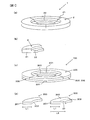
- FIG. 1 shows a configuration of the focus ring 1 according to the embodiment.
- the focus ring 1 is a combined body formed by joining three partial members 2, and is formed in an annular shape.
- One partial member 2 constituting the focus ring 1 has a shape shown in FIG.
- the partial member 2 has a joint surface 21 to be joined to the other partial member 2 and a stepped portion 22, and the focus ring 1 is formed by joining the three partial members 2 through the joint surface 21.
- the focus ring 1 is a member provided around the object to be processed in order to reduce non-uniformity in the etching rate of the object to be processed, which is caused by non-uniform plasma distribution when the object to be processed is plasma etched by the plasma processing apparatus. It is.
- the object to be processed can be supported by the stepped portion 22, it is also used as a support tool when the object to be processed is moved or handled.
- the focus ring 1 is similarly exposed to the plasma and etched. Therefore, the focus ring 1 is required to have high etching resistance.
- the number of the partial members 2 forming the focus ring 1 is not limited to the above three, but may be formed by an optimal number of partial members 2 according to the size of the focus ring 1 and the like. . Details of the manufacturing method of the focus ring 1 will be described later.
- the partial member 2 is manufactured from polycrystalline CaF 2 as described above, and has excellent workability and corrosion resistance.
- the relative density of the polycrystalline CaF 2 forming the partial member 2 is set to 94.0% or more.
- the relative density of polycrystalline CaF 2 can be 99.0% or more.
- the average particle diameter of the crystalline particles of polycrystalline CaF 2 forming the partial member 2 is 200 ⁇ m or more.
- the relative density of polycrystalline CaF 2 in the present application is the density of polycrystalline CaF 2 measured using the Archimedes method, and the ratio of the density of polycrystalline CaF 2 to the density of single crystal CaF 2 is expressed as a percentage.
- SEM scanning electron microscope
- CaF 2 is a stable fluoride having low deliquescence as compared with MgF 2 and BaF 2 which are fluorides. Further, CaF 2 is effective as a plasma-resistant member and a crucible member because it is excellent in fluorine plasma resistance, HF (hydrogen fluoride) resistance, chemical resistance, and heat resistance.
- Single crystal CaF 2 is used as a lens material because it has high transmittance characteristics from the high ultraviolet region to the infrared region. However, since the single crystal CaF 2 has a cleavage property, it has a property of being easily broken by vibration or impact. On the other hand, since the polycrystalline CaF 2 is configured by bonding fine crystals, it is less likely to break than the single crystal CaF 2 in that it does not have a cleavage property as a bulk.
- the etching resistance (etching resistance) will be described in particular as the corrosion resistance of the polycrystalline CaF 2 crystal particles.
- the average particle diameter of the crystalline particles of polycrystalline CaF 2 used for manufacturing the partial member 2 of the present embodiment is 200 ⁇ m or more. According to the inventor's research, it has been clarified that in polycrystalline CaF 2 , the corrosion resistance increases as the crystal particle diameter increases, and the corrosion resistance is saturated when the crystal particle diameter becomes 200 ⁇ m or more. Since the etching proceeds from the crystal interface, if the crystal interface is reduced by increasing the crystal particle diameter, the interface that is likely to be etched decreases.
- Polycrystalline CaF 2 used in the present embodiment has an average particle diameter of 200 ⁇ m or more, and its corrosion resistance is close to that of single crystal CaF 2 . Presumed. Therefore, the polycrystalline CaF 2 used in the embodiment has the advantage of the single crystal body having excellent corrosion resistance in addition to the advantage of the polycrystalline body having no cleavage property.
- Method for producing a partial member 2 made of polycrystalline CaF 2 having the above-described characteristics are as follows. First, polycrystalline CaF 2 having a relative density of 94.0% or more and an average particle diameter of crystal particles of 200 ⁇ m or more is obtained as follows.
- the particle size (median diameter) of the CaF 2 powder raw material is preferably 3 ⁇ m or less, more preferably 0.5 ⁇ m or less.
- the particle size of the CaF 2 powder raw material is large, it is preferably used after being pulverized in advance by a ball mill or the like.
- a CIP method cold isostatic pressing
- a casting method a CaF 2 powder raw material is temporarily formed by a die press, the temporary formed body is made into a vacuum pack, then set in a CIP apparatus, and held at a pressure of, for example, 100 MPa for 1 minute. Is a way to create.
- a slurry prepared by mixing a CaF 2 powder raw material and water is placed in a gypsum mold, for example, left at room temperature for 48 hours or more to obtain a molded body, and then the molded body is taken out from the gypsum mold. And drying in a drying oven at 80 ° C. for 48 hours.
- the molded body obtained as described above is introduced into a vacuum sintering furnace and sintered in a vacuum atmosphere.
- the degree of vacuum during the sintering step is desirably 10 Pa or less for the purpose of densification and prevention of CaF 2 oxidation.
- the compact is sintered at 1400 ° C. or lower for 6 hours or longer.
- 1400 ° C. are the following temperature CaF 2 mp.
- the molded body of polycrystalline CaF 2 is processed into a desired shape. And it grind
- the joining surface 21 of one partial member 2 manufactured as described above is brought into contact with the joining surface 21 of the other partial member 2 and heated to a predetermined temperature in a vacuum atmosphere or an inert gas atmosphere.
- Each partial member 2 is pressurized so that a load of 1 MPa or more is applied to the contact surface 21.
- the focus ring 1 shown in FIG. 1 is manufactured.
- the focus ring 1 is excellent in corrosion resistance and workability and can be easily increased in size by joining the partial members 2 manufactured using the polycrystalline CaF 2 of the present embodiment.
- FIG. 1C is a modification of the focus ring 1.
- the focus ring 100 shown in FIG. 1C is a combined body formed by joining a total of six partial members of three partial members 200 and three partial members 300.
- the partial member 200 and the partial member 300 have the shape shown in FIG.
- the width L1 of the partial member 200 and the width L2 of the partial member 300 in the radial direction of the focus ring 100 are set to different lengths, and the length of the width L2 is longer than the width L1.
- the partial members 200 are bonded to each other via the bonding surface 201, and the partial members 300 are bonded to each other via the bonding surface 301.
- the partial member 200 and the partial member 300 are bonded via the bonding surface 202 and the bonding surface 302.
- a surface 303 to which the partial member 200 is not bonded is provided on the same plane as the bonding surface 302 of the partial member 300. It can.
- the surface 303 to which the partial member 200 is not joined functions as a step portion of the focus ring 100.
- the six partial members may be assembled into a focus ring shape, and the six partial members may be crimped at the same time, or from the annular member made up of the partial members 200 and the partial members 300 together.
- An annular member may be formed, and the annular members may be combined and bonded together.
- the number of the partial members 200 and 300 forming the focus ring 100 is not limited to the above-described six members, and is determined by the optimal number of the partial members 200 and 300 according to the size of the focus ring 100 and the like. It may be formed.
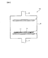
- FIG. 2 is a schematic view of a plasma processing apparatus provided with the focus ring 1 described above.
- an upper electrode 8 and a lower electrode 9 are provided in a chamber 5 having a gas supply port 6 and a gas discharge port 7.
- An electrostatic chuck 11 and a focus ring 1 for supporting the workpiece 3 are provided on the upper surface of the lower electrode 9.
- the electrostatic chuck 11 is disposed so as to be surrounded by the focus ring 1. By disposing the workpiece 3 on the electrostatic chuck 11, the periphery of the workpiece 3 is surrounded by the focus ring 1.
- an etching gas is supplied from the gas supply port 6 while the chamber 5 is evacuated. At this time, a high frequency voltage is applied to the upper electrode 8 and the lower electrode 9. The high frequency electric field formed between the upper electrode 8 and the lower electrode 9 turns the etching gas into plasma and generates plasma. The workpiece 3 is etched by this plasma.
- the focus ring 1 is also exposed to plasma in the same manner as the workpiece 3. Therefore, as the material of the focus ring 1, the polycrystalline CaF 2 according to the present embodiment having excellent corrosion resistance can be suitably used.
- Example preparation A CaF 2 powder raw material having a median diameter of 32.7 ⁇ m was prepared and pulverized by a ball mill to prepare a raw material having a median diameter of 3 ⁇ m or less. Using this raw material, molding was performed using the above-described casting method. That is, a slurry prepared by mixing CaF 2 raw material with water was put in a gypsum mold and allowed to stand at room temperature for 48 hours or more, then removed from the gypsum mold and dried at 80 ° C. for 48 hours in a drying furnace. A molded body was produced.
- the obtained molded body is sintered by heating at 1250 ° C. in vacuum for 6 hours.
- a sample having a sample size of 3 mm ⁇ 4 mm ⁇ 5 mm was cut out by cutting and grinding the molded body taken out after sintering. Thereafter, both surfaces of the sample were mirror-polished so that the surface roughness Ra of the joint surface was 0.16 to 1.64 ⁇ m.
- Examples 1 to 8, Comparative Examples 1 to 4 The sample was introduced into a vacuum furnace, and a load was applied in a state where the joint surfaces were in contact with each other, so that the atmosphere in the furnace was 10 MPa or less. Thereafter, the temperature was raised to a desired temperature over 6 hours, and the sample was pressed by holding at the target temperature. This target temperature is called the holding temperature. The holding at the holding temperature was performed for 6 hours, and then cooled and the sample was taken out. It was confirmed whether or not the sample was pressure-bonded under various conditions in which the holding temperature, the applied pressure, and the surface roughness Ra of the sample were varied.
- the lower limit of the holding temperature is 500 ° C.
- the holding temperature exceeds 800 ° C.
- the sample is easily crimped.
- the holding temperature is set to 1400 ° C. or lower.
- the holding temperature when the sample is pressed is set to 800 ° C. to 1200 ° C.
- the pressure applied when the sample is pressed is set to 0.9 to 1.8 MPa.
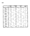
- FIG. 3 shows the crimping results of Examples 1 to 8 and Comparative Examples 1 to 4 in which the surface roughness Ra, the holding temperature, and the applied pressure are different.
- Examples 1 to 3 show the results of pressure bonding when the holding temperature is 1200 ° C., the applied pressure is 1.8 MPa, and the surface roughness Ra of the sample is varied.
- Examples 4 to 6 show the pressure bonding results when the holding temperature is 1200 ° C., the applied pressure is 0.9 MPa, and the surface roughness Ra of the sample is varied.
- Examples 7 and 8 and Comparative Example 1 show the results of pressure bonding when the holding temperature is 1000 ° C., the applied pressure is 0.9 MPa, and the surface roughness Ra of the sample is varied.
- Comparative Examples 2 to 4 show the crimping results when the holding temperature is 800 ° C., the applied pressure is 0.9 MPa, and the surface roughness Ra of the sample is varied.
- “ ⁇ ” indicates that the sample was pressed
- “X” indicates that the sample was not pressed. That is, the samples of Examples 1 to 8 are pressure-bonded, and Comparative Examples 1 to 4 are not pressure-bonded.
- the surface roughness Ra of each sample is 0.16 ⁇ m, 0.19 ⁇ m, and 0.17 ⁇ m, which can be regarded as substantially equal surface roughness Ra.
- the holding temperature is desirably 1000 ° C. or higher.
- the holding temperature is 1000 ° C. or higher and the surface of the joining surface 21 of the partial member 2
- the roughness Ra is preferably 1.0 ⁇ m or less.
- the focus ring 1 can be manufactured by joining the joining surfaces 21 of the partial members 2 by pressure bonding based on the result shown in FIG. 3. As a result, the focus ring 1 can be manufactured without using a material that becomes a source of contamination of the workpiece 3 such as an adhesive or a band member.
- Plasma resistant members typified by focus rings for plasma processing apparatuses tend to increase in size as the diameter of silicon wafers increases.
- a large focus ring from CaF 2
- by joining a plurality of partial members 2 it is possible to prevent a decrease in material yield and manufacturing yield, suppress an increase in cost, and increase the size of the focus ring 1.
- the partial member 2 is made of polycrystalline CaF 2 having a relative density of 94.0% or more and an average particle diameter of crystal grains of 200 ⁇ m or more. Therefore, the focus ring 1 excellent in workability and corrosion resistance can be provided by joining these partial members 2.
- the present invention is not limited to the above-described embodiments, and other forms conceivable within the scope of the technical idea of the present invention are also included in the scope of the present invention. .
Landscapes
- Chemical & Material Sciences (AREA)
- Engineering & Computer Science (AREA)
- Ceramic Engineering (AREA)
- Organic Chemistry (AREA)
- Materials Engineering (AREA)
- Structural Engineering (AREA)
- Physics & Mathematics (AREA)
- Analytical Chemistry (AREA)
- Plasma & Fusion (AREA)
- Inorganic Chemistry (AREA)
- Geology (AREA)
- Life Sciences & Earth Sciences (AREA)
- Manufacturing & Machinery (AREA)
- Drying Of Semiconductors (AREA)
- Ceramic Products (AREA)
- Compositions Of Oxide Ceramics (AREA)
- Chemical Vapour Deposition (AREA)
- Plasma Technology (AREA)
Abstract
Description
本発明の第2の態様によると、第1の態様の多結晶CaF2部材において、多結晶体の結晶粒子の平均粒子径が200μm以上であることが好ましい。
本発明の第3の態様によると、第1または2の態様の多結晶CaF2部材において、多結晶体の相対密度が94.0%以上であることが好ましい。
本発明の第4の態様によると、プラズマ処理装置用部材は、第1乃至3のいずれか一態様の多結晶CaF2部材からなる。
本発明の第5の態様によると、プラズマ処理装置用部材は、第4の態様のプラズマ処理装置用部材はフォーカスリングである。
本発明の第6の態様によると、プラズマ処理装置は、第4または5の態様のプラズマ処理装置用部材を備える。
本発明の第7の態様によると、フォーカスリングの製造方法は、多結晶CaF2からなる複数の部分部材を用意することと、複数の部分部材同士を圧着し、一つの多結晶CaF2部材を形成することとを有する。
本発明の第8の態様によると、第7の態様のフォーカスリングの製造方法において、複数の部分部材同士を圧着する際の保持温度は、1000度以上1200度以下であることが好ましい。
本発明の第9の態様によると、第8の態様のフォーカスリングの製造方法において、複数の部分部材同士を圧着する際の加圧力は、0.9Mpa以上1.8Mpa以下であることが好ましい。
本発明の第10の態様によると、第9の態様のフォーカスリングの製造方法において、複数の部分部材のそれぞれは、圧着の際に他の部分部材と接合する接合面を有し、接合面の面粗さは1.0μm以下であることが好ましい。
CaF2の粉末原料の粒径(メジアン径)は、好ましくは3μm以下であり、より好ましくは0.5μm以下である。CaF2の粉末原料の粒径が大きい場合には、ボールミル等により予め粉砕してから用いるのが好ましい。
[試料の作製]
メジアン径が32.7μmのCaF2粉末原料を準備し、ボールミルにて粉砕処理することにより、メジアン径が3μm以下の原料を調整した。この原料を用いて、上述した鋳込み法を用いて成形を行った。すなわち、CaF2原料を水と混合して作製したスラリーを石膏型に入れ、室温にて48時間以上静置させた後、石膏型から取り出して乾燥炉内で80℃にて48時間乾燥させて成形体を作製した。
試料は真空炉に導入されて、接合面を接触させた状態で荷重を加え、炉内雰囲気を10MPa以下とした。その後、6時間かけて所望の温度まで昇温を行い、目的温度で保持することにより試料の圧着を行った。この目的温度を保持温度と呼ぶ。保持温度での保持は6時間行い、その後、冷却して試料を取り出した。保持温度と、加圧力と、試料の面粗さRaとを異ならせた種々の条件下において、試料が圧着するか否かを確認した。
日本国特許出願2012年第151367号(2012年7月5日出願)
10…プラズマ処理装置
Claims (10)
- CaF2からなる複数の多結晶体を圧着した組み合わせ体からなる多結晶CaF2部材。
- 請求項1に記載の多結晶CaF2部材において、
前記多結晶体の結晶粒子の平均粒子径が200μm以上である多結晶CaF2部材。 - 請求項1または2に記載の多結晶CaF2部材において、
前記多結晶体の相対密度が94.0%以上である多結晶CaF2部材。 - 請求項1乃至3のいずれか一項に記載の多結晶CaF2部材からなるプラズマ処理装置用部材。
- 請求項4に記載のプラズマ処理装置用部材はフォーカスリングであるプラズマ処理装置用部材。
- 請求項4または5に記載のプラズマ処理装置用部材を備えるプラズマ処理装置。
- 多結晶CaF2からなる複数の部分部材を用意することと、
前記複数の部分部材同士を圧着し、一つの多結晶CaF2部材を形成することとを有するフォーカスリングの製造方法。 - 請求項7に記載のフォーカスリングの製造方法において、
前記複数の部分部材同士を圧着する際の保持温度は、1000度以上1200度以下であるフォーカスリングの製造方法。 - 請求項8に記載のフォーカスリングの製造方法において、
前記複数の部分部材同士を圧着する際の加圧力は、0.9Mpa以上1.8Mpa以下であるフォーカスリングの製造方法。 - 請求項9に記載のフォーカスリングの製造方法において、
前記複数の部分部材のそれぞれは、前記圧着の際に他の部分部材と接合する接合面を有し、前記接合面の面粗さは1.0μm以下であるフォーカスリングの製造方法。
Priority Applications (4)
| Application Number | Priority Date | Filing Date | Title |
|---|---|---|---|
| CN201380035575.0A CN104428271B (zh) | 2012-07-05 | 2013-07-04 | 多晶CaF2构件、用于等离子体处理装置的构件、等离子体处理装置及聚焦环的制造方法 |
| JP2014523791A JP6146413B2 (ja) | 2012-07-05 | 2013-07-04 | 組み合わせ体、プラズマ処理装置用部材、プラズマ処理装置およびフォーカスリングの製造方法 |
| KR1020147036577A KR102059221B1 (ko) | 2012-07-05 | 2013-07-04 | 다결정 CaF2 부재, 플라즈마 처리 장치용 부재, 플라즈마 처리 장치 및 포커스 링의 제조 방법 |
| US14/589,404 US10074523B2 (en) | 2012-07-05 | 2015-01-05 | Polycrystalline CaF2 member, member for plasma treatment device, plasma treatment device, and method for producing focusing ring |
Applications Claiming Priority (2)
| Application Number | Priority Date | Filing Date | Title |
|---|---|---|---|
| JP2012151367 | 2012-07-05 | ||
| JP2012-151367 | 2012-07-05 |
Related Child Applications (1)
| Application Number | Title | Priority Date | Filing Date |
|---|---|---|---|
| US14/589,404 Continuation US10074523B2 (en) | 2012-07-05 | 2015-01-05 | Polycrystalline CaF2 member, member for plasma treatment device, plasma treatment device, and method for producing focusing ring |
Publications (1)
| Publication Number | Publication Date |
|---|---|
| WO2014007339A1 true WO2014007339A1 (ja) | 2014-01-09 |
Family
ID=49882090
Family Applications (1)
| Application Number | Title | Priority Date | Filing Date |
|---|---|---|---|
| PCT/JP2013/068395 Ceased WO2014007339A1 (ja) | 2012-07-05 | 2013-07-04 | 多結晶CaF2部材、プラズマ処理装置用部材、プラズマ処理装置およびフォーカスリングの製造方法 |
Country Status (6)
| Country | Link |
|---|---|
| US (1) | US10074523B2 (ja) |
| JP (1) | JP6146413B2 (ja) |
| KR (1) | KR102059221B1 (ja) |
| CN (1) | CN104428271B (ja) |
| TW (1) | TWI612186B (ja) |
| WO (1) | WO2014007339A1 (ja) |
Cited By (3)
| Publication number | Priority date | Publication date | Assignee | Title |
|---|---|---|---|---|
| JP5615454B1 (ja) * | 2014-02-25 | 2014-10-29 | コバレントマテリアル株式会社 | フォーカスリング |
| KR101739795B1 (ko) | 2016-10-27 | 2017-06-08 | (주)코마테크놀로지 | 에지링 및 그의 제조방법 |
| JP2018022803A (ja) * | 2016-08-04 | 2018-02-08 | 日本新工芯技株式会社 | リング状電極 |
Families Citing this family (3)
| Publication number | Priority date | Publication date | Assignee | Title |
|---|---|---|---|---|
| KR200483130Y1 (ko) * | 2012-10-20 | 2017-04-18 | 어플라이드 머티어리얼스, 인코포레이티드 | 세그먼트화된 포커스 링 조립체 |
| JP2017030979A (ja) * | 2013-12-25 | 2017-02-09 | 株式会社ニコン | フッ化カルシウム部材、その製造方法、及びフッ化カルシウム結晶の圧着方法 |
| WO2022145019A1 (ja) * | 2020-12-28 | 2022-07-07 | 株式会社ニコン | フッ化カルシウム焼結体、フッ化カルシウム粒子の製造方法、フッ化カルシウム焼結体の製造方法、光学素子、光学系、交換レンズおよび光学装置 |
Citations (5)
| Publication number | Priority date | Publication date | Assignee | Title |
|---|---|---|---|---|
| JPH06298574A (ja) * | 1993-04-12 | 1994-10-25 | Toshiba Ceramics Co Ltd | セラミック接合体及びその接合方法 |
| JP2000072554A (ja) * | 1998-08-20 | 2000-03-07 | Taiheiyo Cement Corp | 弗化物セラミックス焼結体およびその製造方法 |
| JP2005317900A (ja) * | 2004-03-29 | 2005-11-10 | Tokyo Electron Ltd | 真空装置、そのパーティクルモニタ方法、及びプログラム、並びにパーティクルモニタ用窓部材 |
| JP2011003730A (ja) * | 2009-06-18 | 2011-01-06 | Mitsubishi Materials Corp | プラズマ処理装置用シリコンリング |
| WO2012165334A1 (ja) * | 2011-05-27 | 2012-12-06 | 株式会社ニコン | CaF2多結晶体、フォーカスリング、プラズマ処理装置及びCaF2多結晶体の製造方法 |
Family Cites Families (6)
| Publication number | Priority date | Publication date | Assignee | Title |
|---|---|---|---|---|
| US6529362B2 (en) * | 1997-03-06 | 2003-03-04 | Applied Materials Inc. | Monocrystalline ceramic electrostatic chuck |
| JP3618048B2 (ja) * | 1998-09-14 | 2005-02-09 | 京セラ株式会社 | 半導体製造装置用部材 |
| CN1460094A (zh) * | 2001-04-12 | 2003-12-03 | 揖斐电株式会社 | 陶瓷接合体、其制造方法以及半导体晶片用陶瓷结构体 |
| CN100418187C (zh) * | 2003-02-07 | 2008-09-10 | 东京毅力科创株式会社 | 等离子体处理装置、环形部件和等离子体处理方法 |
| US7464581B2 (en) * | 2004-03-29 | 2008-12-16 | Tokyo Electron Limited | Vacuum apparatus including a particle monitoring unit, particle monitoring method and program, and window member for use in the particle monitoring |
| JP2009290087A (ja) | 2008-05-30 | 2009-12-10 | Tokyo Electron Ltd | フォーカスリング及びプラズマ処理装置 |
-
2013
- 2013-07-04 CN CN201380035575.0A patent/CN104428271B/zh active Active
- 2013-07-04 JP JP2014523791A patent/JP6146413B2/ja active Active
- 2013-07-04 WO PCT/JP2013/068395 patent/WO2014007339A1/ja not_active Ceased
- 2013-07-04 KR KR1020147036577A patent/KR102059221B1/ko active Active
- 2013-07-05 TW TW102124104A patent/TWI612186B/zh active
-
2015
- 2015-01-05 US US14/589,404 patent/US10074523B2/en active Active
Patent Citations (5)
| Publication number | Priority date | Publication date | Assignee | Title |
|---|---|---|---|---|
| JPH06298574A (ja) * | 1993-04-12 | 1994-10-25 | Toshiba Ceramics Co Ltd | セラミック接合体及びその接合方法 |
| JP2000072554A (ja) * | 1998-08-20 | 2000-03-07 | Taiheiyo Cement Corp | 弗化物セラミックス焼結体およびその製造方法 |
| JP2005317900A (ja) * | 2004-03-29 | 2005-11-10 | Tokyo Electron Ltd | 真空装置、そのパーティクルモニタ方法、及びプログラム、並びにパーティクルモニタ用窓部材 |
| JP2011003730A (ja) * | 2009-06-18 | 2011-01-06 | Mitsubishi Materials Corp | プラズマ処理装置用シリコンリング |
| WO2012165334A1 (ja) * | 2011-05-27 | 2012-12-06 | 株式会社ニコン | CaF2多結晶体、フォーカスリング、プラズマ処理装置及びCaF2多結晶体の製造方法 |
Cited By (6)
| Publication number | Priority date | Publication date | Assignee | Title |
|---|---|---|---|---|
| JP5615454B1 (ja) * | 2014-02-25 | 2014-10-29 | コバレントマテリアル株式会社 | フォーカスリング |
| JP2018022803A (ja) * | 2016-08-04 | 2018-02-08 | 日本新工芯技株式会社 | リング状電極 |
| WO2018025782A1 (ja) * | 2016-08-04 | 2018-02-08 | 日本新工芯技株式会社 | リング状電極 |
| US10553405B2 (en) | 2016-08-04 | 2020-02-04 | Thinkon New Technology Japan Corporation | Ring-shaped electrode |
| TWI742127B (zh) * | 2016-08-04 | 2021-10-11 | 日商日本新工芯技股份有限公司 | 環狀電極 |
| KR101739795B1 (ko) | 2016-10-27 | 2017-06-08 | (주)코마테크놀로지 | 에지링 및 그의 제조방법 |
Also Published As
| Publication number | Publication date |
|---|---|
| KR20150035778A (ko) | 2015-04-07 |
| JPWO2014007339A1 (ja) | 2016-06-02 |
| CN104428271A (zh) | 2015-03-18 |
| US20150107768A1 (en) | 2015-04-23 |
| JP6146413B2 (ja) | 2017-06-14 |
| KR102059221B1 (ko) | 2019-12-24 |
| TW201420821A (zh) | 2014-06-01 |
| CN104428271B (zh) | 2017-03-08 |
| TWI612186B (zh) | 2018-01-21 |
| US10074523B2 (en) | 2018-09-11 |
Similar Documents
| Publication | Publication Date | Title |
|---|---|---|
| JP6146413B2 (ja) | 組み合わせ体、プラズマ処理装置用部材、プラズマ処理装置およびフォーカスリングの製造方法 | |
| US8622021B2 (en) | High lifetime consumable silicon nitride-silicon dioxide plasma processing components | |
| US8236428B2 (en) | Hybrid silicon wafer and method for manufacturing same | |
| TWI820786B (zh) | 用於耐電漿材料之氧化釔-氧化鋯燒結陶瓷及其製造方法 | |
| KR102818334B1 (ko) | 에칭 적용을 위한 제어된 다공성 산화이트륨 | |
| JP7595668B2 (ja) | セラミック部品及びセラミック部品の製造方法 | |
| CN117800716A (zh) | 包含铝酸镁尖晶石的陶瓷烧结体 | |
| JP5949760B2 (ja) | CaF2多結晶体、フォーカスリング、プラズマ処理装置及びCaF2多結晶体の製造方法 | |
| CN116134003A (zh) | 大尺寸的烧结氧化钇体 | |
| WO2022250097A1 (ja) | フォーカスリングおよびプラズマ処理装置 | |
| JP4762168B2 (ja) | アルミナ質焼結体及びこれを用いた処理装置用部材ならびに処理装置 | |
| JP4570195B2 (ja) | 炭化硼素接合体及びその製造方法及び耐プラズマ部材 | |
| JP2016124734A (ja) | 耐食性部材、静電チャック装置および耐食性部材の製造方法 | |
| JP5185213B2 (ja) | 耐プラズマ性フッ化物焼結体の製造方法 | |
| JP2009203113A (ja) | プラズマ処理装置用セラミックス | |
| JP2000247728A (ja) | 耐食性に優れたアルミナセラミックス焼結体 | |
| KR102352039B1 (ko) | 정전척의 에지링 제조방법 및 이로부터 제조된 에지링을 포함하는 정전척 | |
| JP2007214288A (ja) | 静電チャック | |
| JP2015015439A (ja) | プラズマ処理装置用部材、プラズマ処理装置およびプラズマ処理装置用部材の製造方法 | |
| JP2016154178A (ja) | 静電チャック用部材及びその製造方法 | |
| JP2005281054A (ja) | 酸化アルミニウム質焼結体及びその製造方法並びにこれを用いた半導体、液晶製造装置部材 | |
| JP2009004752A (ja) | 静電チャック | |
| JP2008195546A (ja) | プラズマ処理装置用セラミックスおよびその製造方法 |
Legal Events
| Date | Code | Title | Description |
|---|---|---|---|
| 121 | Ep: the epo has been informed by wipo that ep was designated in this application |
Ref document number: 13813189 Country of ref document: EP Kind code of ref document: A1 |
|
| ENP | Entry into the national phase |
Ref document number: 2014523791 Country of ref document: JP Kind code of ref document: A |
|
| ENP | Entry into the national phase |
Ref document number: 20147036577 Country of ref document: KR Kind code of ref document: A |
|
| NENP | Non-entry into the national phase |
Ref country code: DE |
|
| 122 | Ep: pct application non-entry in european phase |
Ref document number: 13813189 Country of ref document: EP Kind code of ref document: A1 |