WO2014007233A1 - 耐震補強構造 - Google Patents
耐震補強構造 Download PDFInfo
- Publication number
- WO2014007233A1 WO2014007233A1 PCT/JP2013/068109 JP2013068109W WO2014007233A1 WO 2014007233 A1 WO2014007233 A1 WO 2014007233A1 JP 2013068109 W JP2013068109 W JP 2013068109W WO 2014007233 A1 WO2014007233 A1 WO 2014007233A1
- Authority
- WO
- WIPO (PCT)
- Prior art keywords
- reinforcing
- existing
- column
- steel
- building
- Prior art date
- Legal status (The legal status is an assumption and is not a legal conclusion. Google has not performed a legal analysis and makes no representation as to the accuracy of the status listed.)
- Ceased
Links
Images





Classifications
-
- E—FIXED CONSTRUCTIONS
- E04—BUILDING
- E04G—SCAFFOLDING; FORMS; SHUTTERING; BUILDING IMPLEMENTS OR AIDS, OR THEIR USE; HANDLING BUILDING MATERIALS ON THE SITE; REPAIRING, BREAKING-UP OR OTHER WORK ON EXISTING BUILDINGS
- E04G23/00—Working measures on existing buildings
- E04G23/02—Repairing, e.g. filling cracks; Restoring; Altering; Enlarging
- E04G23/0218—Increasing or restoring the load-bearing capacity of building construction elements
-
- E—FIXED CONSTRUCTIONS
- E04—BUILDING
- E04B—GENERAL BUILDING CONSTRUCTIONS; WALLS, e.g. PARTITIONS; ROOFS; FLOORS; CEILINGS; INSULATION OR OTHER PROTECTION OF BUILDINGS
- E04B1/00—Constructions in general; Structures which are not restricted either to walls, e.g. partitions, or floors or ceilings or roofs
- E04B1/62—Insulation or other protection; Elements or use of specified material therefor
- E04B1/92—Protection against other undesired influences or dangers
- E04B1/98—Protection against other undesired influences or dangers against vibrations or shocks; against mechanical destruction, e.g. by air-raids
Definitions
- the present invention relates to a seismic reinforcement structure, and more particularly to a seismic reinforcement structure on the outer surface of an existing multistory building of RC or SRC.
- a reinforced concrete structure (hereinafter referred to as RC structure) and a steel-framed reinforced concrete structure (hereinafter referred to as SRC structure) are applied to a multi-story building as shown in FIG. 11, for example.
- RC structure a reinforced concrete structure
- SRC structure steel-framed reinforced concrete structure
- pillars and beams are indispensable for this, but the shaft 33 formed by the pillars 31 and the beams 32 located on the outer wall side includes a waist wall, a vertical wall, a door, and a window (not shown in the figure). Etc.) are provided.
- the pillar supports the load on the upper floor, and the beam is integrated with the floor slab 34 on each floor.
- the upper beam in the frame is displaced in the horizontal direction with respect to the lower beam, and the left and right columns are inclined in the same direction. Therefore, although the shaft set is a parallelogram, the beam is reversely displaced by swinging back and the column is also a parallelogram inclined in the reverse direction, and this is repeated for a certain time.
- bracing as described in Japanese Patent Application Laid-Open No. 2004-169504 is required when “construction while staying” and “avoidance of narrowing the field of view” are required when applying seismic reinforcement to the outer surface of an RC building or the like.
- the less method is applied. That is, a reinforcing column is integrated with an existing column (also referred to as an RC column), a reinforcing beam is also integrated with an existing beam (also referred to as an RC beam), and a new frame is formed by the reinforcing column and the reinforcing beam. I am doing so.
- Japanese Patent Application Laid-Open No. 2007-138472 proposes a seismic reinforcement method in which a reinforcing column is integrated with an RC column, but a reinforcing beam is not integrated with an RC beam.
- the reason why the reinforcing beam is not integrated with the existing beam is not clarified, but if the reinforcing column is integrated with the existing column, the column strengthened by the combination improves the earthquake resistance of the building.
- the reinforcing columns are made of steel when they are continuously joined to each other by anchor bolts or the like so as to integrate the reinforcing columns with the existing columns as in Patent Document 2, the deformation is generally larger than that of the existing RC columns.
- the RC column is overwhelmed by deformation of the steel column and cracks are induced in the concrete from anchor bolts or the like.
- this type of problem can be solved by the technique of Patent Document 1 which attempts to approximate bending rigidity.
- the existing beams are integrated with the floor slab.
- the earthquake resistance is higher than that of the pillar. This means that it is indispensable to increase the earthquake resistance of existing columns beyond the reinforcement of existing beams.
- the present invention has been made in view of the above problems.
- the purpose of the present invention is to reinforce the frame on the outer surface of a structure such as RC, and there is inherently a difference in the earthquake resistance between existing columns and existing beams.
- the present invention is applied to a seismic reinforcement structure on the outer surface of an RC or SRC multi-story existing building.
- the feature of the present invention is that an existing column located on the outer wall side of the existing building with reference to FIG.
- the reinforcing pillar 8 is erected so as to face without being fixed to the existing pillar.
- the lower part of the reinforcing column 8 is connected to the reinforcing beam 9L fixed to the existing beam 1L integrated with the floor slab 5L, and the upper part of the reinforcing column 8 is integrated with the upper floor slab 5U. It is connected to the reinforcing beam 9U fixed to 1U.
- the reinforcing beams 9 fixed to the same existing beam are discontinuous with the adjacent reinforcing beams on the left and right.
- Reinforcing columns and beams are made of shaped steel as shown in FIGS. 1 and 5, for example.
- the reinforcing column 8 may be provided with a vibration damping mechanism 23 that absorbs energy by deformation of the vibration control steel plate made of extremely low yield point steel.
- the concrete space 13 may be filled in the surrounding space of the reinforcing column 8.
- Reinforcing columns and reinforcing beams can be replaced with RC steel reinforcing columns 28 and RC reinforcing beams 29 as shown in FIG.
- the reinforcing columns are bridged over the reinforcing beams fixed to the upper and lower existing beams, but are not integrated with the existing columns. Even if there is a difference in the deformation of the existing column, the existing column is hardly affected by the deformation of the reinforcing column. In other words, if a small amount of space is left in the facing part between the existing column and the reinforcing column, the existing column is released from following the deformation of the reinforcing column, so cracking in the existing column is possible. Can be suppressed.
- the reinforcing column is supported by the existing beam having high earthquake resistance via the reinforcing beam, the reinforcing column is not dropped off, and the I-shaped reinforcing frame structure by the reinforcing column and the reinforcing beam is also maintained.
- Reinforcing beams fixed to the same existing beam are made discontinuous with the adjacent reinforcing beams on the left and right, so that the horizontal length of the reinforcing beams is kept long enough to support the reinforcing columns. Can do. The amount of work and the amount of input materials required to fix the reinforcing beam to the existing beam are reduced, which is convenient because it shortens the construction period.
- the reinforcing columns and beams are made of steel, it will be possible to save labor in on-site assembly work by introducing factory-processed products, compared to the reinforcement with pure concrete structure. If a space of the desired width is secured at the facing part of the existing column and the reinforcing column, it can be used for the installation work space to the reinforcing column such as the vibration control mechanism adopting the vibration control steel plate made of extremely low yield point steel It becomes possible to introduce a vibration control mechanism that greatly enhances the energy absorption effect during a large earthquake.
- the shape of the reinforced beam formation is used for buildings with an uneven surface such as the outer surface of the existing column is more outward than the outer surface of the existing beam. It also increases the degree of freedom.
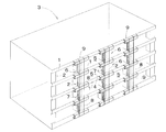
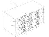
- FIG. 2 is an external view in which a seismic reinforcement of an I-shaped reinforcing shaft structure based on the configuration of FIG. 1 is applied to the outer surface of a multi-story existing RC structure.
- Sectional drawing and front view of the principal part at the time of making a reinforcement pillar and a reinforcement beam into RC structure The external view which applied the RC reinforcement pillar and the reinforcement beam to the building where a part of existing pillar has come out outside the existing beam.
- FIG. 2 shows a building 3 in which the existing beam 1 protrudes outward (frontward) from the existing column 2 (see the upper left portion toward the outer surface of the external view) as in FIG.
- a shaft group 4 is formed by two of the existing beams 1 facing up and down and the two of the existing columns 2 facing left and right, which form one part of the dwelling unit or the outer surface of one room.
- the existing beam 1 and the floor slab 5 are integrated, and the connecting portion is not visible, but the floor slab 5 extends in the dwelling unit.
- the existing pillar 2 supports the existing beam 1 integrated with the floor slab 5, and the load is transmitted to the existing pillar 2 below the floor to reach the foundation.
- the following composition is given as the seismic reinforcement of such a building.
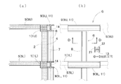
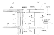
- the first example is shown in FIG. 1 and shows the main part when the I-shaped reinforcing shaft 6 made of welded flat groove steel is applied to the right side, the left side or both sides of the frame 4 of the existing building. It is sectional drawing and a front view.
- the reinforcing column 8 is arranged on the outer part of the existing column 2 located on the building outer wall side in the existing building so that the reinforcing column 8 faces the space 7 between the existing column.
- the reinforcing beam 9L is fixed to the existing beam 1L integrated with the floor slab 5L, and the existing beam 1U integrated with the floor slab 5U on the upper floor is reinforced.
- the beam 9U is fixed.
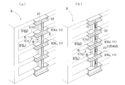
- the reinforcing columns 8 are integrated and connected in a standing state so as to be sandwiched between the reinforcing beam 9L and the reinforcing beam 9U, and the reinforcing shaft 6 is formed. As shown in FIG.
- the reinforcing beam 9 is much shorter than the existing beam 1, and the reinforcing beam 9L fixed to the existing beam 1L is discontinuous with the reinforcing beams adjacent on the left and right.
- the reinforcing beam 9U fixed to the existing beam 1U is also discontinuous with the reinforcing beams adjacent on the left and right.
- the cross-sectional shape is, for example, U-shaped as shown in FIG. This can be off-the-shelf channel steel, or a welded steel made by welding steel plates that have been cut to fit the desired size, such as when there are no ready-made dimensions or expensive ones. Good.
- the section steel 10 having a small cross-sectional area is depicted, but the size and shape of the groove shape are arbitrarily selected as necessary. In any case, since it is a cutting work and can-making in the factory, the manufacturing accuracy is high.
- the reinforcing columns and beams are welded shape steel such as welded flat groove steel and welded H-shape steel, or commercially available shape steel, it is possible to assemble on-site assembly work by adopting factory-processed products compared to the reinforcement by pure concrete structure. Significant labor saving is achieved.
- the shape steel whether it is a welded product (non-standard product) or a commercial standard product, depends on the space surrounded by the web or flange or the applied formwork (not shown), etc. Filling the enclosed space with concrete 13 is performed as necessary (see, for example, FIG. 1B). This makes it easy to increase the bending rigidity of the reinforcing column, and it is possible to increase the selection range of the bending rigidity to be achieved depending on the specifications of the shape steel and the amount of filled concrete.
- the concrete 14 is filled as shown in FIG. 1A and anchors (not shown) are embedded to the existing beam of the reinforcing beam. Strong integration is achieved.
- the reinforcing steel beam can be easily integrated with the existing beam by known means such as using an anchor or a PC steel bar.
- the reinforcing columns are assembled to the reinforcing beams in advance at the factory, and the above I-shaped or T-shaped reinforcing shafts are assembled, and the lower and upper floor shafts are welded or bolted together at the site construction. By doing so, a reinforcing body having a desired height can be formed. This facilitates the progress of the work by improving the handleability by shortening the reinforcing beam.
- the reinforcement pillar 8 faces the outer part of the existing pillar 2 with a space 7 between the existing pillar 2 and the existing pillar 2. Is done.
- the intention of “arranged with a space” is that they are not fixed to each other and try to cut off load transmission between the existing column and the reinforcing column. Therefore, if the existing column and the reinforcing column are as close as possible, and the space is not apparently recognizable, the effect of the present invention is exhibited.
- FIG. 4 is an example applied to a building in which the outer surface of the existing beam 1 and the outer surface of the existing column 2 are flush with each other, the reinforcing column 8 is made narrower than the reinforcing beam 9 to secure the space 7. It is possible.
- the reinforcing columns 8 are arranged as far as possible outward.
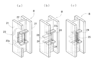
- a vibration control mechanism may be interposed in the web of the reinforcing column 8. This is designed so that energy can be absorbed by deformation of the damping steel plate made of extremely low yield point steel.
- the existence of the facing space with the existing column is nothing but the installation work space for the reinforcing column such as the vibration control mechanism and the plastic deformation allowable space. This measure greatly enhances the energy absorption effect in the event of a large earthquake.
- FIG. 6 The details of an example of the vibration control mechanism 23 are shown in FIG. 6 (drawn exaggeratedly), but as shown in FIG.
- the vibration-suppressing steel plate 23a made of ultra-low yield point steel is fitted at that position.
- FIG. 6 shows several abutting plates 24 from the front and back of the web, the vertical reinforcing plate 25 shown in (c), etc. support the damping steel plate 23a and prevent large deformation.
- FIG. 7 is a cross-sectional view and a front view of the main part of an example of a reinforcing column made of welded steel and a reinforcing beam applied to a building in which the outer surface of the existing column 2 protrudes outward from the existing beam 1.
- the reinforcing beam 9 made of welded H-shaped steel is provided with a notch 26 in which the center of the planar shape accommodates the front portion of the existing pillar 2 as shown in FIG.
- the RC reinforcing beam 29 may be used. Even if the toughness is inferior to that of welded steel, the outer surface of the existing column 2 is more outward than the outer surface of the existing beam 1 (see FIGS. 7 and 7). 9), the shape freedom in forming the reinforcing beam is improved.
- the reinforcing column is not integrated with the existing column when it is bridged between the reinforcing beams fixed to the upper and lower existing beams. Therefore, even if there is a difference between the deformation of the reinforcing column and the deformation of the existing column, the existing column is extremely less affected by the reinforcing column, that is, the facing space is freed from following the deformation of the reinforcing column in the existing column. Therefore, the occurrence of cracks in existing pillars can be suppressed as much as possible. Since the reinforcing column is supported by the existing beam having high earthquake resistance via the reinforcing beam, the reinforcing column is not dropped and the frame structure by the reinforcing column and the reinforcing beam is maintained.
- Reinforcement beams fixed to the same existing beam are made discontinuous with adjacent reinforcement beams on the left and right sides, so that the horizontal length of the reinforcement beams is long enough to support the reinforcement columns. You can keep it.
- the amount of work and the amount of input materials required to fix the reinforcing beam to the existing beam can be significantly reduced as compared with the case where the reinforcing beam is continuously fixed to the existing beam, which is advantageous for shortening the construction period.
- the reinforcing beams are made continuous, the beams will be strengthened, which in turn causes a decrease in the relative strength of the columns that should have been reinforced, but this should be avoided. it can.
- the reinforcement has been described to cover the entire surface of the building, but it should be applied to any part of the building, such as up to the middle floor, only the middle floor, or only the left half of the outer surface. Can do. If the construction in that case is handled as a repetition of each floor unit, the concept of partial reinforcement becomes possible and the construction can be distributed.
- the fact that the reinforcing beams are lined up discontinuously with the existing beams means that there will be virtually no load, but the length of the reinforcing beams lined up at the left and right is different, The side lengths of the reinforcing beams are different on the left and right at the border as needed.
- a light frame or a decorative frame, for example, may be provided between the reinforcing beams and used for another purpose.
Landscapes
- Engineering & Computer Science (AREA)
- Architecture (AREA)
- Civil Engineering (AREA)
- Structural Engineering (AREA)
- Chemical Kinetics & Catalysis (AREA)
- Mechanical Engineering (AREA)
- Electrochemistry (AREA)
- Chemical & Material Sciences (AREA)
- Environmental & Geological Engineering (AREA)
- Physics & Mathematics (AREA)
- Electromagnetism (AREA)
- Working Measures On Existing Buildindgs (AREA)
- Buildings Adapted To Withstand Abnormal External Influences (AREA)
Description
RC造補強梁29としてもよい。靱性は溶接形鋼製より劣るにしても、既存柱2の外面が既存梁1の外面よりも外方となっているなど外面凹凸の施されたデザインの建物にあっては(図7および図9を参照)、補強梁の形成における形状自由度は向上する。
Claims (5)
- RC造やSRC造多層階既存建物の外面における耐震補強構造において、
既存建物における建物外壁側に位置する既存柱の外方部位には、既存柱に固着されることなく補強柱が対面するように立設され、
該補強柱の下部は床スラブと一体化されている既存梁に固着させた補強梁に連ねられるとともに、補強柱の上部は上階床スラブと一体化されている既存梁に固着させた補強梁に連ねられ、
同一既存梁に固着の補強梁は、左右で隣りあう補強梁と相互に不連続になっていることを特徴とする耐震補強構造。 - 前記補強柱および補強梁は、形鋼製であることを特徴とする請求項1に記載された耐震補強構造。
- 前記補強柱には極低降伏点鋼製制震鋼板の変形によりエネルギ吸収する制振機構が介在されていることを特徴とする請求項2に記載された耐震補強構造。
- 前記補強柱または補強梁における囲繞空間にはコンクリートが充填されていることを特徴とする請求項2に記載された耐震補強構造。
- 前記補強梁および補強柱はRC造であることを特徴とする請求項1に記載された耐震補強構造。
Priority Applications (3)
| Application Number | Priority Date | Filing Date | Title |
|---|---|---|---|
| JP2014523746A JP5993948B2 (ja) | 2012-07-02 | 2013-07-02 | 耐震補強構造 |
| CN201380029077.5A CN104508219B (zh) | 2012-07-02 | 2013-07-02 | 抗震加强结构 |
| KR1020147036302A KR101652621B1 (ko) | 2012-07-02 | 2013-07-02 | 기존 건물의 내진 구조물 |
Applications Claiming Priority (2)
| Application Number | Priority Date | Filing Date | Title |
|---|---|---|---|
| JP2012-148503 | 2012-07-02 | ||
| JP2012148503 | 2012-07-02 |
Publications (1)
| Publication Number | Publication Date |
|---|---|
| WO2014007233A1 true WO2014007233A1 (ja) | 2014-01-09 |
Family
ID=49881989
Family Applications (1)
| Application Number | Title | Priority Date | Filing Date |
|---|---|---|---|
| PCT/JP2013/068109 Ceased WO2014007233A1 (ja) | 2012-07-02 | 2013-07-02 | 耐震補強構造 |
Country Status (5)
| Country | Link |
|---|---|
| JP (1) | JP5993948B2 (ja) |
| KR (1) | KR101652621B1 (ja) |
| CN (1) | CN104508219B (ja) |
| TW (1) | TWI527954B (ja) |
| WO (1) | WO2014007233A1 (ja) |
Cited By (3)
| Publication number | Priority date | Publication date | Assignee | Title |
|---|---|---|---|---|
| CN105888091A (zh) * | 2014-11-27 | 2016-08-24 | 王振牛 | 一种永乐宫壁画体系防地震及背面维护技术方案 |
| WO2017090052A1 (en) * | 2015-05-26 | 2017-06-01 | WADKAR, Omneel | A method of constructing earthquake resistant structure with reinforced foundation and wall structure |
| JP2017150225A (ja) * | 2016-02-24 | 2017-08-31 | 株式会社竹中工務店 | 耐震補強構造 |
Families Citing this family (1)
| Publication number | Priority date | Publication date | Assignee | Title |
|---|---|---|---|---|
| CN111828041B (zh) * | 2020-06-23 | 2022-06-24 | 中电建南方建设投资有限公司 | 地铁地下长纵结构混凝土温度应力锚定系统 |
Citations (3)
| Publication number | Priority date | Publication date | Assignee | Title |
|---|---|---|---|---|
| JP2001040881A (ja) * | 1999-08-02 | 2001-02-13 | Maeda Corp | 柱梁接合部の補強構造 |
| JP2002089053A (ja) * | 2000-09-21 | 2002-03-27 | Oriental Construction Co Ltd | PCaコンクリート部材による既存建築物の補強構造 |
| JP2004169504A (ja) * | 2002-11-22 | 2004-06-17 | Katsuhiko Imai | Rc造用ブレースレス耐震補強工法 |
Family Cites Families (4)
| Publication number | Priority date | Publication date | Assignee | Title |
|---|---|---|---|---|
| JP3254602B2 (ja) * | 1996-11-22 | 2002-02-12 | 日本鋼管株式会社 | 耐震部材、その製造方法及び耐震部材の取付構造 |
| JP4721273B2 (ja) | 2005-11-16 | 2011-07-13 | 株式会社フジタ | 鉄筋コンクリート造ラーメン構造の既存建物の耐震補強工法 |
| CN201809873U (zh) * | 2009-10-31 | 2011-04-27 | 白风山 | 房屋加固抗震梁 |
| CN101906882B (zh) * | 2010-07-06 | 2011-12-07 | 华南理工大学 | 一种对既有砌体结构采用钢部件进行抗震加固的方法 |
-
2013
- 2013-07-02 KR KR1020147036302A patent/KR101652621B1/ko active Active
- 2013-07-02 JP JP2014523746A patent/JP5993948B2/ja active Active
- 2013-07-02 WO PCT/JP2013/068109 patent/WO2014007233A1/ja not_active Ceased
- 2013-07-02 TW TW102123654A patent/TWI527954B/zh active
- 2013-07-02 CN CN201380029077.5A patent/CN104508219B/zh active Active
Patent Citations (3)
| Publication number | Priority date | Publication date | Assignee | Title |
|---|---|---|---|---|
| JP2001040881A (ja) * | 1999-08-02 | 2001-02-13 | Maeda Corp | 柱梁接合部の補強構造 |
| JP2002089053A (ja) * | 2000-09-21 | 2002-03-27 | Oriental Construction Co Ltd | PCaコンクリート部材による既存建築物の補強構造 |
| JP2004169504A (ja) * | 2002-11-22 | 2004-06-17 | Katsuhiko Imai | Rc造用ブレースレス耐震補強工法 |
Cited By (3)
| Publication number | Priority date | Publication date | Assignee | Title |
|---|---|---|---|---|
| CN105888091A (zh) * | 2014-11-27 | 2016-08-24 | 王振牛 | 一种永乐宫壁画体系防地震及背面维护技术方案 |
| WO2017090052A1 (en) * | 2015-05-26 | 2017-06-01 | WADKAR, Omneel | A method of constructing earthquake resistant structure with reinforced foundation and wall structure |
| JP2017150225A (ja) * | 2016-02-24 | 2017-08-31 | 株式会社竹中工務店 | 耐震補強構造 |
Also Published As
| Publication number | Publication date |
|---|---|
| CN104508219A (zh) | 2015-04-08 |
| KR101652621B1 (ko) | 2016-08-30 |
| KR20150032264A (ko) | 2015-03-25 |
| TW201407021A (zh) | 2014-02-16 |
| JP5993948B2 (ja) | 2016-09-21 |
| CN104508219B (zh) | 2017-07-18 |
| TWI527954B (zh) | 2016-04-01 |
| JPWO2014007233A1 (ja) | 2016-06-02 |
Similar Documents
| Publication | Publication Date | Title |
|---|---|---|
| JP2004169504A (ja) | Rc造用ブレースレス耐震補強工法 | |
| JP5993948B2 (ja) | 耐震補強構造 | |
| JP2020037775A (ja) | ノンブレース鉄骨造建物その構築方法および柱脚ユニット | |
| JP6053485B2 (ja) | 既存建物への間柱の設置構造 | |
| JP2011069148A (ja) | 建物の構造 | |
| JP7849691B2 (ja) | 増設補強フレーム架構の着装構造体およびその構築法 | |
| JP2025175189A (ja) | 制振建物 | |
| JP6265735B2 (ja) | 連結建物 | |
| JP6019710B2 (ja) | 既存建物の耐震補強構造及び方法 | |
| JP5957321B2 (ja) | 既存建物の外付け補強構造および既存建物の補強方法 | |
| JP2016056679A (ja) | 板状集合住宅の柱梁構造 | |
| JP6293207B2 (ja) | 既存建物への間柱の設置構造 | |
| JP7300355B2 (ja) | 開口部を有する建築物 | |
| JP2007277856A (ja) | 既存建物の耐震補強構造 | |
| JP6951851B2 (ja) | 高層耐震建物 | |
| JP2017044009A (ja) | 免震建物の基礎構造 | |
| JP6617608B2 (ja) | 板状建築物の柱梁構造 | |
| JP3804174B2 (ja) | ロ字型骨組架構による既存建築物の耐震改修方法 | |
| KR102819262B1 (ko) | 모듈화한 중공단열 구조체 | |
| KR102577800B1 (ko) | 층고 절감형 거더 및 이의 시공방법 | |
| JP7443643B2 (ja) | 壁構造 | |
| JPH09221829A (ja) | 鉄筋コンクリート構造物の制振装置 | |
| JP2022187181A (ja) | 多層建築物 | |
| JP2015203264A (ja) | 梁および柱・梁構造 | |
| JP2023085078A (ja) | 構造物 |
Legal Events
| Date | Code | Title | Description |
|---|---|---|---|
| 121 | Ep: the epo has been informed by wipo that ep was designated in this application |
Ref document number: 13812640 Country of ref document: EP Kind code of ref document: A1 |
|
| ENP | Entry into the national phase |
Ref document number: 2014523746 Country of ref document: JP Kind code of ref document: A |
|
| ENP | Entry into the national phase |
Ref document number: 20147036302 Country of ref document: KR Kind code of ref document: A |
|
| NENP | Non-entry into the national phase |
Ref country code: DE |
|
| 122 | Ep: pct application non-entry in european phase |
Ref document number: 13812640 Country of ref document: EP Kind code of ref document: A1 |