WO2014002700A1 - 試料冷却ホルダー及び冷却源容器 - Google Patents
試料冷却ホルダー及び冷却源容器 Download PDFInfo
- Publication number
- WO2014002700A1 WO2014002700A1 PCT/JP2013/065427 JP2013065427W WO2014002700A1 WO 2014002700 A1 WO2014002700 A1 WO 2014002700A1 JP 2013065427 W JP2013065427 W JP 2013065427W WO 2014002700 A1 WO2014002700 A1 WO 2014002700A1
- Authority
- WO
- WIPO (PCT)
- Prior art keywords
- cooling
- sample
- cooling source
- source container
- holder
- Prior art date
- Legal status (The legal status is an assumption and is not a legal conclusion. Google has not performed a legal analysis and makes no representation as to the accuracy of the status listed.)
- Ceased
Links
Images


Classifications
-
- H—ELECTRICITY
- H01—ELECTRIC ELEMENTS
- H01J—ELECTRIC DISCHARGE TUBES OR DISCHARGE LAMPS
- H01J37/00—Discharge tubes with provision for introducing objects or material to be exposed to the discharge, e.g. for the purpose of examination or processing thereof
- H01J37/02—Details
- H01J37/20—Means for supporting or positioning the object or the material; Means for adjusting diaphragms or lenses associated with the support
-
- H—ELECTRICITY
- H01—ELECTRIC ELEMENTS
- H01J—ELECTRIC DISCHARGE TUBES OR DISCHARGE LAMPS
- H01J37/00—Discharge tubes with provision for introducing objects or material to be exposed to the discharge, e.g. for the purpose of examination or processing thereof
- H01J37/26—Electron or ion microscopes; Electron or ion diffraction tubes
-
- H—ELECTRICITY
- H01—ELECTRIC ELEMENTS
- H01J—ELECTRIC DISCHARGE TUBES OR DISCHARGE LAMPS
- H01J2237/00—Discharge tubes exposing object to beam, e.g. for analysis treatment, etching, imaging
- H01J2237/18—Vacuum control means
- H01J2237/184—Vacuum locks
-
- H—ELECTRICITY
- H01—ELECTRIC ELEMENTS
- H01J—ELECTRIC DISCHARGE TUBES OR DISCHARGE LAMPS
- H01J2237/00—Discharge tubes exposing object to beam, e.g. for analysis treatment, etching, imaging
- H01J2237/20—Positioning, supporting, modifying or maintaining the physical state of objects being observed or treated
- H01J2237/2001—Maintaining constant desired temperature
-
- H—ELECTRICITY
- H01—ELECTRIC ELEMENTS
- H01J—ELECTRIC DISCHARGE TUBES OR DISCHARGE LAMPS
- H01J2237/00—Discharge tubes exposing object to beam, e.g. for analysis treatment, etching, imaging
- H01J2237/20—Positioning, supporting, modifying or maintaining the physical state of objects being observed or treated
- H01J2237/2002—Controlling environment of sample
-
- H—ELECTRICITY
- H01—ELECTRIC ELEMENTS
- H01J—ELECTRIC DISCHARGE TUBES OR DISCHARGE LAMPS
- H01J2237/00—Discharge tubes exposing object to beam, e.g. for analysis treatment, etching, imaging
- H01J2237/20—Positioning, supporting, modifying or maintaining the physical state of objects being observed or treated
- H01J2237/202—Movement
- H01J2237/20207—Tilt
Definitions
- the present invention relates to a sample cooling holder used in a charged particle apparatus (for example, a focused ion beam processing observation apparatus (FIB apparatus), a transmission electron microscope (TEM), or a scanning transmission electron microscope (STEM)).
- a charged particle apparatus for example, a focused ion beam processing observation apparatus (FIB apparatus), a transmission electron microscope (TEM), or a scanning transmission electron microscope (STEM)
- the present invention also relates to a cooling source container (Dewar) suitable for mounting on a sample cooling holder (Specimen CryoyHolder).
- the FIB apparatus is an apparatus that can process a sample into an arbitrary shape by irradiating the sample with focused charged particles.
- the FIB apparatus having a microprobe can extract a micro sample from an arbitrary location of the sample.
- This extraction method is called FIB microsampling method.
- the FIB microsampling method is a method suitable for preparation of a sample that is necessary when performing state analysis or structural analysis on the order of several nanometers, which is a nanotechnology research object, using an electron microscope or the like (Patent Document 1).
- Patent Document 2 a method of cooling a sample under observation has been proposed (Patent Document 2).
- the sample cooling holder proposed in Patent Document 2 cannot efficiently transfer the heat of the cooling source to the sample, and is capable of barely cooling the sample.
- this type of sample cooling holder requires a mechanism that can tilt the direction of the sample.
- a container hereinafter referred to as “cooling source container” containing a cooling source (for example, liquid nitrogen) is fixed to an inclination mechanism.
- a cooling source for example, liquid nitrogen
- the temperature of the sample may rise depending on the processing conditions even during processing by the FIB apparatus.
- a heat-sensitive resin, a low-melting-point metal, a low-temperature phase change product, or the like it is preferable to process the sample while cooling it.
- the present invention has been made in consideration of the above problems, and provides a sample cooling holder with a tilt function, which enables cooling of a sample during processing or observation, and a cooling source container therefor To do.
- the sample cooling holder according to the present invention has a mechanism that can cool the sample while maintaining the posture of the cooling source container in a certain direction even when the sample is inclined in a direction suitable for processing or observation.
- the cooling source container according to the present invention has a vacuum holding mechanism in the outer container that insulates the inner container holding the cooling source from outside air by vacuum insulation.
- the sample cooling holder according to the present invention makes it possible to tilt the sample in a direction suitable for processing or observation using charged particles while efficiently cooling the sample. Further, when the cooling source container according to the present invention is used, it is possible to improve the vacuum heat insulation performance during observation or processing, and it is possible to maintain the cooling of the sample by the cooling source for a long period of time. Problems, configurations, and effects other than those described above will become apparent from the following description of embodiments.
- FIG. 1A shows the positional relationship between the charged particles and the sample during processing
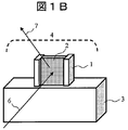
- FIG. 1B shows the positional relationship between the charged particles and the sample during observation.
- Sample 1 is a micro sample prepared by, for example, the FIB micro sampling method.
- the processing / observation region 2 provided in the sample 1 is 10 ⁇ m square or less in the case of normal processing / observation. Note that the sample 1 is directly bonded to the cooling sample stage 3 cooled by a cooling source.
- charged particles 5 for example, an ion beam
- charged particles 6 for example, electron beams
- processing and observation can be performed while the sample 1 is cooled.
- the processing / observation region 2 is close to the cooled sample stage 3 at a distance of several ⁇ m or less. For this reason, a high cooling effect can be expected.
- the signal 7 (for example, characteristic X-rays, secondary electrons (reflected electrons)) output from the sample 1 passes through the space 4 and is efficiently detected by the detector.
- the holder to which the cooling sample stage 3 is attached is provided with a mechanism capable of tilting the sample in the vertical direction of the paper, and can be processed and observed according to the purpose. .
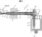
- FIG. 2 shows a state in which the sample cooling holder 13 equipped with the cooling source container is attached to the holder receiving portion 11 of the charged particle device.
- the sample cooling holder 13 is attached to the holder receiving portion 11 through the O-ring 12 so as to be slidable and / or rotatable.
- the sample cooling holder rotates the shutter 19 constituting the outer cylinder, the heat shield 18 constituting the inner cylinder, the L-shaped cooling rod 14 in which a part of the rod is accommodated in the inner cylinder, and the heat shield 18.
- a cooling source container mounting portion 15 that holds the cooling rod 14 while holding the cooling rod 14 is possible.
- the cooling source container mounting portion 15 holds the cooling rod 14 in a state where a part of the cooling rod 14 is inserted into an opening provided on the lower surface side thereof.
- a part of the cooling rod 14 protrudes from the lower surface of the cooling source container mounting part 15, and a part of the rod comes into contact with the cooling source 16 when the cooling source container is mounted on the lower surface of the cooling source container mounting part 15. .
- the cooling rod 14 is neither fixed to the inside of the heat shield 18 nor to the inside of the cooling source container mounting portion 15.
- a lock mechanism 26 is used. When the lock mechanism 26 in this embodiment is pushed in, the lock rod 14 is pressed against the inside of the heat shield 18 to be locked, and when pushed in again, the lock state is released.
- the cooling source container is fixedly attached to the cooling source container mounting portion 15 through screws or the like.
- the cooling source container mounting portion 15 and the heat shield 18 are rotatably attached by an O-ring 20.
- the shutter 19 is reciprocally attached along the surface of the heat shield 18 through an O-ring 20.
- the tip portion (sample mounting side) of the heat shield 18 is partially cut so that the two opposing arms protrude in the axial direction, and the cooled sample is interposed between the two arms. It is comprised so that the base support stand 10 can be hold
- the cooled sample stage support 10 and the cooling rod 14 are connected through a flexible cooling transmission member (for example, a cylindrical metal mesh) 17.
- the flexible cooling transmission member 17 is a deformable member. For this reason, the cooled sample stage support 10 is separated from the cooling rod 14, and only the cooled sample stage support 10 can be tilted independently of the cooling rod 14 (rotated in the axial direction of the heat shield 18).
- the cooling sample support 10 is equipped with a cooling support 3 to which the sample 1 is attached. Therefore, being able to incline the cooling sample stage support base 10 independently with respect to the cooling rod 14 means that the sample 1 can be inclined independently with respect to the cooling rod 14.
- Non-Patent Document 1 The process until the sample 1 is fixed to the cooled sample stage 3 is existing (Non-Patent Document 1). For this reason, description of the process is omitted.
- the cooled sample stage support 10 is fixed to the heat shield 18, when the heat shield 18 is rotated with respect to the cooling source container mounting portion 15, the cooled sample stage support 10 is also integrated with the heat shield 18. It rotates and the direction of the sample 1 rotates. As described above, the cooling sample stage support 10 and the heat shield 18 can be rotated because the cooling sample stage support 10 and the cooling rod 14 are connected through the flexible cooling transmission member 17.
- the cooled sample table 3 can be removed from the cooled sample table support table 10 after the completion of processing and observation.
- the cooling sample table 3 can be mounted on the cooling sample table support table 10 at the time of processing / observation again.
- the structure for detachably attaching the cooled sample stage 3 to the cooled sample stage support 10 will be described later.
- a holder tip shield 9 and a holder tip shield presser 8 are attached to the tip of the heat shield 18 in order.
- the holder front end shield 9 is a member that tightly contacts the end of the shutter 19 and seals the inside of the shutter 19 when the shutter 19 is slid in the front end direction along the axis of the heat shield 18.
- the holder tip shield presser 8 is a member that prevents the holder tip shield 9 from falling off.
- the cooling source container has a double container structure of an inner cooling source container 23 that holds a cooling source (for example, liquid nitrogen) 16 and an outer cooling source container 21 that accommodates the inner cooling source container 23 with a heat shield 22 interposed therebetween. ing.
- the heat shield 22 is kept in a vacuum state. For this reason, the inner cooling source container 23 is thermally isolated from the outside of the outer cooling source container 21 by the heat shield 22.
- Two openings are formed in the upper surface of the inner cooling source container 23, the cooling rod 14 is inserted into one opening, and the other opening is used for introducing the cooling source.
- a vacuum exhaust port 24 is formed on the lower surface of the outer cooling source container 21, and a vacuum holding cap 25 is attached to the vacuum exhaust port 24.
- the vacuum exhaust port 24 is used for vacuum exhaust of the heat shield 22.
- the vacuum holding cap 25 is used to hold a high vacuum state of the heat shield 22 after evacuation.
- the cooling source container can be attached to and detached from the sample cooling holder using screws or the like.
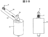
- FIG. 3A shows the positional relationship between the sample and charged particles and the positional relationship between the sample cooling holder and the cooling source container when the sample is processed.
- FIG. 3B shows the positional relationship between the sample and charged particles and the positional relationship between the sample cooling holder and the cooling source container when the sample is observed.
- the direction perpendicular to the paper surface is the longitudinal direction of the sample cooling holder 13.
- the sample 1 is arranged in parallel to a charged particle 5 (here, an ion beam) emitted from an objective lens (not shown), and is processed and observed.
- a thin film sample is produced in a cooled state.
- the heat from the cooling source 16 propagates to the sample 1 through the cooling rod 14, the flexible cooling transmission member 17, the cooling sample stage support 10 and the cooling sample stage 3.
- the cooling rod 14 is in an unlocked state. Since the lock is released, the cooling rod 14 does not rotate with the heat shield 18 even if the tilt angle of the sample 1 is changed (that is, the heat shield 18 is rotated around the central axis).
- the cooling source container does not rotate with the cooling source container mounting portion 15. That is, the cooling source 16 held in the cooling source container is held in a horizontal state. Even if bubbling occurs in the cooling source 16 due to an external factor or the like, the vibration is propagated exclusively through the flexible cooling transmission member 17 and is damped. Accordingly, it is possible to effectively prevent a decrease in processing accuracy and observation accuracy.
- the thin film sample is arranged substantially at right angles to the charged particles 6 (here, electron beams).
- the arrangement of the sample 1 in FIG. 3B is inclined by 90 degrees from the direction of the thin film sample preparation in FIG. 3A.
- the cooling rod 14 is in the unlocked state.
- the integral rotation of the shutter 19 and the heat shield 18 is absorbed by deformation of the flexible cooling transmission member 17 in the torsional direction. Therefore, the rotation (inclination) of the shutter 19 and the heat shield 18 does not affect the rotation (inclination) of the cooling rod 14.
- the locking mechanism 26 is also in the unlocked state during observation. Thereby, the horizontal state of the cooling source 16 held in the inner cooling source container 23 can be maintained without being constrained in the processing / observation direction of the thin film sample.
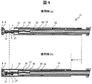
- the shutter 19 is provided to avoid sample breakage and contamination when the sample cooling holder 13 is transported between apparatuses.
- the usage example (a) shown in the upper part of FIG. 4 shows the position of the shutter 19 during sample processing / observation
- the usage example (b) shown in the lower part of FIG. 4 shows the position of the shutter 19 during conveyance.
- the shutter 19 that constitutes the outer cylinder slides in the distal direction along the surface of the heat shield 18 that constitutes the inner cylinder, and a sealed space is formed in a state where the end face is in contact with the holder distal shield 9.
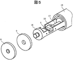
- FIG. 5 shows the structure of the tip of the sample cooling holder 13.
- the material of the holder tip shield 9 is arbitrary.
- a material for example, rubber
- the sample 1 is evacuated through the sample cooling holder 13 by evacuating through the vacuum exhaust port 28 formed in the housing of the heat shield 18. It is possible to move between devices while keeping Further, when a material made of resin and having heat resistance (for example, a fluororesin) is used as the holder tip shield 9, the sample 1 can be rapidly frozen by directly immersing the tip of the sample cooling holder 13 in a cooling medium.
- a material made of resin and having heat resistance for example, a fluororesin
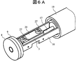
- FIG. 6A and FIG. 6B are used to show a structure for attaching the cooling sample stage 3 to the sample cooling holder 13.
- 6A shows a mounting structure on the back side with respect to the mounting surface of the cooling sample table 3
- FIG. 6B shows a configuration viewed from the mounting surface side of the cooling sample table 3.
- FIG. In the case of the present embodiment, a structure is adopted in which the cooled sample table 3 is sandwiched from both sides by the cooled sample table support table 10 and the cooled sample table holder 29 and fixed with fixing screws 27.
- the one-letter screw groove formed on the head of the fixing screw 27 does not penetrate to both ends of the head, and as shown in FIG. 6A, both ends of the screw groove remain inside the head, and both ends are rectangular or both ends.
- the part forms a semicircular elongated hole.
- the cooling sample stage support 10 is provided on the heat shield 18 in order to reliably transmit the heat transmitted from the cooling source 16 through the cooling rod 14 and the flexible cooling transmission member 17 to the sample 1. It is fixed with four pointed parts 30 protruding from both sides of the arm.
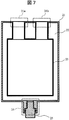
- FIG. 7 shows a cross-sectional structure of the cooling source container.
- the cooling source container that can be attached to and detached from the sample cooling holder 13 is a cylindrical inner cooling source container 23 that holds a cooling source (for example, liquid nitrogen) 16 and a cylindrical shape that houses the inner cooling source container 23 with the heat shield 22 interposed therebetween.
- the outer cooling source container 21 is configured.
- Two openings are formed in the upper surface of the inner cooling source container 23, and a cylindrical tube is attached above each of the two openings. One ends of these two pipes are connected to a hole having the same shape provided in the outer cooling source container 21. By this connection, the space surrounded by the inner cooling source container 23 and the outer cooling source container 21 forms a heat shield 22.
- One of the two openings is used as a cooling rod insertion port 31a for inserting the cooling rod 14, and the other is used as a cooling source introduction port 31b for introducing the cooling source 16.
- the names of the cooling rod insertion port 31a and the cooling source introduction port 31b are convenient, and either of them may be used for the insertion of the cooling rod 14 and the other may be used for the introduction of the cooling source 16.
- a vacuum exhaust port 24 is formed on the lower surface of the outer cooling source container 21, and a vacuum holding cap 25 is attached to the vacuum exhaust port 24.
- the vacuum exhaust port 24 is used for vacuum exhaust of the heat shield 22.
- the vacuum holding cap 25 is used to hold a high vacuum state of the heat shield 22 after evacuation.
- the temperature of the cooling source 16 is transmitted to the sample 1 through the cooling rod 14, the flexible cooling transmission member 17, the cooling sample stage support 10 and the cooling sample stage 3. Therefore, observation and processing can be performed while the sample 1 is cooled. Since the flexible cooling transmission member 17 is excellent in thermal conductivity, a sufficient amount of heat can be propagated to the sample 1.
- a cooled sample stage support 10 on which the sample 1 and the cooled sample stage 3 are mounted is connected through a cooling rod 14 that can be deformed at least in the torsional direction, and the sample 1 is rotated (tilted) independently from the cooling rod 14.
- the cooling rod 14 is not fixed to the heat shield 18 and the cooling source container mounting portion 15 constituting the inner cylinder.
- the cooling source container according to this embodiment is the sample cooling holder 13 (specifically It can be attached to and detached from the cooling source container mounting portion 15). For this reason, when there is no need to cool the sample 1, the cooling source container can be removed from the sample cooling holder 13.
- the vacuum holding cap 25 is provided in the outer cooling source container 21 constituting the outer cylinder, and the degree of vacuum is always high if evacuation is performed each time observation or processing is performed. Observation and processing can be performed in the state. For this reason, the temperature of the cooling source can be maintained for a long time, and it becomes possible to work continuously for a long time. Further, since continuous work is possible, the total work time required for processing and observation can be greatly shortened. Thereby, rapid development of material analysis and research can be realized. In particular, a wide range of applications can be expected in the field of orientational material analysis and research.
- Outer cooling source container 22 ... Heat shield, 23 ... Inner cooling source container, 24 ... Vacuum exhaust port, 25 ... Vacuum holding cap, 26 ... Lock mechanism, 27 ... Fixing screw, 28 ... Vacuum exhaust port, 29 ... Cooling sample table holder, 30 ... Pointed parts, 31a ... cold Rod insertion port, 31b ... cooling source inlet.
Landscapes
- Chemical & Material Sciences (AREA)
- Analytical Chemistry (AREA)
- Sampling And Sample Adjustment (AREA)
- Analysing Materials By The Use Of Radiation (AREA)
- Testing Or Measuring Of Semiconductors Or The Like (AREA)
Priority Applications (4)
| Application Number | Priority Date | Filing Date | Title |
|---|---|---|---|
| KR1020147032399A KR101665221B1 (ko) | 2012-06-28 | 2013-06-04 | 시료 냉각 홀더 및 냉각원 용기 |
| CN201380033422.2A CN104380426B (zh) | 2012-06-28 | 2013-06-04 | 试料冷却支架以及冷却源容器 |
| DE112013003012.8T DE112013003012B4 (de) | 2012-06-28 | 2013-06-04 | Kryo-Probenhalter und Dewargefäss |
| US14/410,235 US9543112B2 (en) | 2012-06-28 | 2013-06-04 | Specimen cryo holder and dewar |
Applications Claiming Priority (2)
| Application Number | Priority Date | Filing Date | Title |
|---|---|---|---|
| JP2012145599A JP5732006B2 (ja) | 2012-06-28 | 2012-06-28 | 試料冷却ホルダー及び冷却源容器 |
| JP2012-145599 | 2012-06-28 |
Publications (1)
| Publication Number | Publication Date |
|---|---|
| WO2014002700A1 true WO2014002700A1 (ja) | 2014-01-03 |
Family
ID=49782866
Family Applications (1)
| Application Number | Title | Priority Date | Filing Date |
|---|---|---|---|
| PCT/JP2013/065427 Ceased WO2014002700A1 (ja) | 2012-06-28 | 2013-06-04 | 試料冷却ホルダー及び冷却源容器 |
Country Status (6)
| Country | Link |
|---|---|
| US (1) | US9543112B2 (https=) |
| JP (1) | JP5732006B2 (https=) |
| KR (1) | KR101665221B1 (https=) |
| CN (1) | CN104380426B (https=) |
| DE (1) | DE112013003012B4 (https=) |
| WO (1) | WO2014002700A1 (https=) |
Cited By (5)
| Publication number | Priority date | Publication date | Assignee | Title |
|---|---|---|---|---|
| EP3032564A1 (en) * | 2014-12-11 | 2016-06-15 | FEI Company | Improved cryogenic specimen holder for a charged particle microscope |
| CN106104250A (zh) * | 2014-04-03 | 2016-11-09 | 株式会社日立高新技术 | 低温存储系统 |
| JP2018060614A (ja) * | 2016-10-03 | 2018-04-12 | 株式会社メルビル | 試料ホルダー |
| EP3247987B1 (de) | 2015-01-20 | 2020-09-02 | Leica Mikrosysteme GmbH | Probentransfereinrichtung |
| JP2023054894A (ja) * | 2021-10-05 | 2023-04-17 | 株式会社メルビル | ステージ |
Families Citing this family (13)
| Publication number | Priority date | Publication date | Assignee | Title |
|---|---|---|---|---|
| WO2016056096A1 (ja) | 2014-10-09 | 2016-04-14 | 株式会社日立ハイテクノロジーズ | 荷電粒子線装置、電子顕微鏡、試料の観察方法 |
| JP6515320B2 (ja) * | 2014-11-19 | 2019-05-22 | 日本製鉄株式会社 | 試料ホルダー及び透過型電子顕微鏡による観察方法 |
| WO2017098574A1 (ja) | 2015-12-08 | 2017-06-15 | 株式会社日立ハイテクノロジーズ | アンチコンタミネーショントラップおよびその制御方法、ならびに荷電粒子線装置 |
| EP4174903A1 (en) | 2017-10-30 | 2023-05-03 | Gatan, Inc. | Cryotransfer holder and workstation |
| EP3710765A4 (en) * | 2017-11-15 | 2021-08-11 | The Coca-Cola Company | SYSTEM AND METHOD FOR RAPID COOLING OF PACKAGED FOOD |
| NL2020235B1 (en) * | 2018-01-05 | 2019-07-12 | Hennyz B V | Vacuum transfer assembly |
| CN113345784B (zh) * | 2020-02-18 | 2023-06-02 | 中国科学院物理研究所 | 一种低温原位样品杆 |
| CN112885687B (zh) * | 2021-04-15 | 2025-04-18 | 厦门超新芯科技有限公司 | 一种透射电镜冷冻样品杆 |
| US12123816B2 (en) * | 2021-06-21 | 2024-10-22 | Fei Company | Vibration-free cryogenic cooling |
| JP2024017051A (ja) * | 2022-07-27 | 2024-02-08 | 日本電子株式会社 | 試料ホルダーおよび荷電粒子線装置 |
| US12548731B2 (en) * | 2022-09-30 | 2026-02-10 | Fei Company | Systems and methods for transferring a sample |
| JP7824658B2 (ja) * | 2023-06-23 | 2026-03-05 | 株式会社ドキュメンタリーチャンネル | 走査電子顕微鏡用の試料冷却装置 |
| WO2025141822A1 (ja) * | 2023-12-27 | 2025-07-03 | 株式会社日立ハイテク | 荷電粒子線装置、試料冷却機構、及び連続断面加工観察方法 |
Citations (4)
| Publication number | Priority date | Publication date | Assignee | Title |
|---|---|---|---|---|
| JPS52123862A (en) * | 1976-04-12 | 1977-10-18 | Hitachi Ltd | Sample cooler of electron beam observation equipment |
| JPH0739729U (ja) * | 1993-12-28 | 1995-07-18 | 幾代 渡辺 | 真空断熱装置 |
| JP2010257617A (ja) * | 2009-04-22 | 2010-11-11 | Hitachi High-Technologies Corp | 試料ホールダ,該試料ホールダの使用法、及び荷電粒子装置 |
| JP2012033335A (ja) * | 2010-07-29 | 2012-02-16 | Hitachi High-Technologies Corp | イオンミリング装置 |
Family Cites Families (13)
| Publication number | Priority date | Publication date | Assignee | Title |
|---|---|---|---|---|
| US4033003A (en) * | 1975-11-07 | 1977-07-05 | Briles Manufacturing | Head forming method |
| US4833330A (en) * | 1987-11-03 | 1989-05-23 | Gatan Inc. | Anticontaminator for transmission electron microscopes |
| JP2774884B2 (ja) | 1991-08-22 | 1998-07-09 | 株式会社日立製作所 | 試料の分離方法及びこの分離方法で得た分離試料の分析方法 |
| US5274237A (en) * | 1992-04-02 | 1993-12-28 | North American Philips Corporation | Deicing device for cryogenically cooled radiation detector |
| EP1102304B1 (en) | 1996-12-23 | 2010-02-24 | Fei Company | Particle-optical apparatus including a low-temperature specimen holder |
| US5753924A (en) * | 1997-03-12 | 1998-05-19 | Gatan, Inc. | Ultra-high tilt specimen cryotransfer holder for electron microscope |
| JPH10275582A (ja) | 1997-03-28 | 1998-10-13 | Jeol Ltd | 電子顕微鏡等の試料加熱・冷却装置 |
| JPH1196953A (ja) | 1997-09-18 | 1999-04-09 | Hitachi Ltd | 冷却試料観察装置 |
| US6414322B1 (en) * | 1999-01-25 | 2002-07-02 | Micron Technology, Inc. | Sample mount for a scanning electron microscope |
| US6410925B1 (en) | 2000-07-31 | 2002-06-25 | Gatan, Inc. | Single tilt rotation cryotransfer holder for electron microscopes |
| JP2007039106A (ja) * | 2005-08-04 | 2007-02-15 | Sii Nanotechnology Inc | 弾性材料を使用した薄板状小片ホルダ |
| CN201348980Y (zh) * | 2008-12-23 | 2009-11-18 | 南京师范大学 | 扫描电镜样品台专用复合型支架 |
| US8336405B2 (en) * | 2010-07-28 | 2012-12-25 | E.A. Fischione Instruments, Inc. | Cryogenic specimen holder |
-
2012
- 2012-06-28 JP JP2012145599A patent/JP5732006B2/ja active Active
-
2013
- 2013-06-04 US US14/410,235 patent/US9543112B2/en active Active
- 2013-06-04 WO PCT/JP2013/065427 patent/WO2014002700A1/ja not_active Ceased
- 2013-06-04 DE DE112013003012.8T patent/DE112013003012B4/de not_active Expired - Fee Related
- 2013-06-04 KR KR1020147032399A patent/KR101665221B1/ko active Active
- 2013-06-04 CN CN201380033422.2A patent/CN104380426B/zh active Active
Patent Citations (4)
| Publication number | Priority date | Publication date | Assignee | Title |
|---|---|---|---|---|
| JPS52123862A (en) * | 1976-04-12 | 1977-10-18 | Hitachi Ltd | Sample cooler of electron beam observation equipment |
| JPH0739729U (ja) * | 1993-12-28 | 1995-07-18 | 幾代 渡辺 | 真空断熱装置 |
| JP2010257617A (ja) * | 2009-04-22 | 2010-11-11 | Hitachi High-Technologies Corp | 試料ホールダ,該試料ホールダの使用法、及び荷電粒子装置 |
| JP2012033335A (ja) * | 2010-07-29 | 2012-02-16 | Hitachi High-Technologies Corp | イオンミリング装置 |
Cited By (9)
| Publication number | Priority date | Publication date | Assignee | Title |
|---|---|---|---|---|
| CN106104250A (zh) * | 2014-04-03 | 2016-11-09 | 株式会社日立高新技术 | 低温存储系统 |
| CN106104250B (zh) * | 2014-04-03 | 2019-12-13 | 株式会社日立高新技术 | 低温存储系统 |
| US10658150B2 (en) | 2014-04-03 | 2020-05-19 | Hitachi High-Technologies Corporation | Cryostation system |
| EP3032564A1 (en) * | 2014-12-11 | 2016-06-15 | FEI Company | Improved cryogenic specimen holder for a charged particle microscope |
| EP3247987B1 (de) | 2015-01-20 | 2020-09-02 | Leica Mikrosysteme GmbH | Probentransfereinrichtung |
| JP2018060614A (ja) * | 2016-10-03 | 2018-04-12 | 株式会社メルビル | 試料ホルダー |
| US10242841B2 (en) | 2016-10-03 | 2019-03-26 | Mel-Build Corporation | Specimen holder |
| JP2023054894A (ja) * | 2021-10-05 | 2023-04-17 | 株式会社メルビル | ステージ |
| JP7734404B2 (ja) | 2021-10-05 | 2025-09-05 | 株式会社メルビル | ステージ |
Also Published As
| Publication number | Publication date |
|---|---|
| US20150340199A1 (en) | 2015-11-26 |
| KR101665221B1 (ko) | 2016-10-11 |
| JP2014010965A (ja) | 2014-01-20 |
| DE112013003012T5 (de) | 2015-03-05 |
| JP5732006B2 (ja) | 2015-06-10 |
| DE112013003012B4 (de) | 2020-02-06 |
| US9543112B2 (en) | 2017-01-10 |
| CN104380426B (zh) | 2017-03-08 |
| KR20150001842A (ko) | 2015-01-06 |
| CN104380426A (zh) | 2015-02-25 |
Similar Documents
| Publication | Publication Date | Title |
|---|---|---|
| JP5732006B2 (ja) | 試料冷却ホルダー及び冷却源容器 | |
| JP6008965B2 (ja) | 改良型低温試料ホルダ | |
| JP5947296B2 (ja) | 低温試料ホルダー | |
| EP3652775B1 (en) | Cryotransfer system | |
| US8602648B1 (en) | X-ray microscope system with cryogenic handling system and method | |
| US20130037706A1 (en) | Devices and methods for cryo lift-out with in situ probe | |
| JPS59500688A (ja) | 微量分析のための低温ステ−ジ | |
| CN105474348B (zh) | 防污染阱以及真空应用装置 | |
| Van Der Linden et al. | A compact and versatile dynamic flow cryostat for photon science | |
| JP5914578B2 (ja) | 凍結含水試料をマイクロプローブへ結合する方法 | |
| JP4302722B2 (ja) | 試料冷却装置及びそれを備えた電子線照射型分析/観察装置 | |
| Fournier et al. | A test cassette for x-ray-exposure experiments at the National Ignition Facility | |
| US3171957A (en) | Specimen holder for an electron microscope with means to support a specimen across a thermocouple junction | |
| Pieper et al. | Versatile system for the temperature-controlled preparation of oxide crystal surfaces | |
| US3720829A (en) | Sample fracturing apparatus | |
| JP7847168B2 (ja) | 集束イオンビーム装置 | |
| Dennison et al. | Ultrahigh vacuum chamber for synchrotron x‐ray diffraction from films adsorbed on single‐crystal surfaces | |
| Ferrer et al. | A multipurpose ultra-high vacuum-compatible chamber for in situ X-ray surface scattering studies over a wide range of temperature and pressure environment conditions | |
| Wang | Ultrafast Electron Diffraction With Solid-State Samples | |
| JP2024017051A (ja) | 試料ホルダーおよび荷電粒子線装置 | |
| Nafisi et al. | Sample mounting and transfer for coupling an ultrahigh vacuum variable temperature beetle scanning tunneling microscope with conventional surface probes | |
| Oreshkin et al. | Crystal cleavage mechanism for UHV scanning tunneling microscopy | |
| Hopkins et al. | Journal of Applied Crystallography ISSN 1600-5767 |
Legal Events
| Date | Code | Title | Description |
|---|---|---|---|
| 121 | Ep: the epo has been informed by wipo that ep was designated in this application |
Ref document number: 13808756 Country of ref document: EP Kind code of ref document: A1 |
|
| ENP | Entry into the national phase |
Ref document number: 20147032399 Country of ref document: KR Kind code of ref document: A |
|
| WWE | Wipo information: entry into national phase |
Ref document number: 14410235 Country of ref document: US Ref document number: 112013003012 Country of ref document: DE Ref document number: 1120130030128 Country of ref document: DE |
|
| 122 | Ep: pct application non-entry in european phase |
Ref document number: 13808756 Country of ref document: EP Kind code of ref document: A1 |