WO2014002685A1 - ガラス基板の切断方法及びガラス基板の製造方法 - Google Patents
ガラス基板の切断方法及びガラス基板の製造方法 Download PDFInfo
- Publication number
- WO2014002685A1 WO2014002685A1 PCT/JP2013/065194 JP2013065194W WO2014002685A1 WO 2014002685 A1 WO2014002685 A1 WO 2014002685A1 JP 2013065194 W JP2013065194 W JP 2013065194W WO 2014002685 A1 WO2014002685 A1 WO 2014002685A1
- Authority
- WO
- WIPO (PCT)
- Prior art keywords
- glass substrate
- laser light
- glass
- cutting
- laser beam
- Prior art date
- Legal status (The legal status is an assumption and is not a legal conclusion. Google has not performed a legal analysis and makes no representation as to the accuracy of the status listed.)
- Ceased
Links
Images




Classifications
-
- B—PERFORMING OPERATIONS; TRANSPORTING
- B23—MACHINE TOOLS; METAL-WORKING NOT OTHERWISE PROVIDED FOR
- B23K—SOLDERING OR UNSOLDERING; WELDING; CLADDING OR PLATING BY SOLDERING OR WELDING; CUTTING BY APPLYING HEAT LOCALLY, e.g. FLAME CUTTING; WORKING BY LASER BEAM
- B23K26/00—Working by laser beam, e.g. welding, cutting or boring
- B23K26/36—Removing material
- B23K26/38—Removing material by boring or cutting
-
- C—CHEMISTRY; METALLURGY
- C03—GLASS; MINERAL OR SLAG WOOL
- C03B—MANUFACTURE, SHAPING, OR SUPPLEMENTARY PROCESSES
- C03B33/00—Severing cooled glass
- C03B33/09—Severing cooled glass by thermal shock
- C03B33/091—Severing cooled glass by thermal shock using at least one focussed radiation beam, e.g. laser beam
-
- B—PERFORMING OPERATIONS; TRANSPORTING
- B23—MACHINE TOOLS; METAL-WORKING NOT OTHERWISE PROVIDED FOR
- B23K—SOLDERING OR UNSOLDERING; WELDING; CLADDING OR PLATING BY SOLDERING OR WELDING; CUTTING BY APPLYING HEAT LOCALLY, e.g. FLAME CUTTING; WORKING BY LASER BEAM
- B23K26/00—Working by laser beam, e.g. welding, cutting or boring
- B23K26/36—Removing material
- B23K26/40—Removing material taking account of the properties of the material involved
-
- B—PERFORMING OPERATIONS; TRANSPORTING
- B23—MACHINE TOOLS; METAL-WORKING NOT OTHERWISE PROVIDED FOR
- B23K—SOLDERING OR UNSOLDERING; WELDING; CLADDING OR PLATING BY SOLDERING OR WELDING; CUTTING BY APPLYING HEAT LOCALLY, e.g. FLAME CUTTING; WORKING BY LASER BEAM
- B23K2103/00—Materials to be soldered, welded or cut
- B23K2103/50—Inorganic materials other than metals or composite materials
-
- B—PERFORMING OPERATIONS; TRANSPORTING
- B23—MACHINE TOOLS; METAL-WORKING NOT OTHERWISE PROVIDED FOR
- B23K—SOLDERING OR UNSOLDERING; WELDING; CLADDING OR PLATING BY SOLDERING OR WELDING; CUTTING BY APPLYING HEAT LOCALLY, e.g. FLAME CUTTING; WORKING BY LASER BEAM
- B23K2103/00—Materials to be soldered, welded or cut
- B23K2103/50—Inorganic materials other than metals or composite materials
- B23K2103/54—Glass
Definitions
- the present invention relates to a glass substrate cutting method and a glass substrate manufacturing method.
- a cutting method using a laser beam has been studied as a method for cutting a glass substrate.
- Patent Document 1 proposes a method of cutting a glass substrate that is forcibly cooled by compressed gas or the like immediately after forming a notch recess having a predetermined depth by irradiating laser light.
- Patent Document 2 proposes a method for cutting a glass substrate in which a glass substrate is irradiated while scanning with laser light, the glass is melted at a portion irradiated with the laser light, and the molten glass is blown off with an assist gas.
- the cut surface has a portion corresponding to a notch recess formed by irradiating a laser beam, and then when forced cooling is performed.
- a portion formed in the lower portion of the notch recess is included, and the surface characteristics of both are different.
- the present invention provides a glass substrate cutting method capable of accurately cutting a glass substrate as compared with a conventional glass substrate cutting method in which an assist gas is blown onto the glass substrate in view of the problems of the prior art. For the purpose.
- the present invention is a glass substrate cutting method for irradiating a laser beam to cut a glass substrate, wherein one surface of the glass substrate is irradiated with the laser beam.
- the laser light irradiation part from one surface of the glass substrate to the other surface is heated to a temperature higher than the vaporization temperature, and the laser light irradiation region is directed to the glass substrate along the planned cutting line of the glass substrate.
- a glass substrate cutting method characterized by relatively moving the glass substrate.
- the glass substrate can be cut with higher accuracy than the method for cutting a glass substrate using a conventional assist gas.
- the glass substrate cutting method of the present invention is a glass substrate cutting method in which a laser beam is irradiated to cut the glass substrate, and has the following configuration.
- heating is performed at a temperature higher than the temperature at which the laser light irradiation portion from one surface of the glass substrate to the other surface is vaporized.
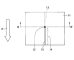
- FIG. 1 schematically shows a configuration in which a glass substrate is cut by the glass substrate cutting method of the present invention as seen from the upper surface of the glass substrate on the side irradiated with laser light (one surface side).
- the glass substrate 11 is conveyed in the direction indicated by the arrow A in FIG. 1, and a portion (laser light irradiation region) irradiated with a laser beam 12 oscillated from a laser oscillation device (not shown) is cut on the glass substrate. It can move along the planned line 13.
- the laser light irradiation portion from one surface to the other surface of the glass substrate is heated (heating step). Then, the region 14 that has already been irradiated with the laser light is separated from the region irradiated with the laser light when the glass substrate 11 is transported, and the laser light irradiated portion after the laser light irradiation (laser light is irradiated to vaporize the glass). The peripheral part of 15 is cooled (cooling step).
- the glass substrate 11 is transported to displace the portion (laser light irradiation region) irradiated with the laser light 12 on the glass substrate 11.
- it is not limited to such a form.
- a portion irradiated with the laser beam 12 (laser beam irradiation region) ) can also be displaced.
- the position of the part which conveys the glass substrate 11 and is irradiated with the laser beam 12 can also be configured to be displaced.
- the cutting line 13 of the glass substrate is shown in the drawing, but the line on the glass substrate is not necessarily provided.
- the planned cutting line is not limited to a straight line, and may be an arbitrary line such as a curve according to the required shape of the glass substrate after cutting.
- composition of the glass substrate to which the glass substrate cutting method of the present invention can be applied is not particularly limited and can be applied to various glass substrates.
- examples thereof include non-alkali borosilicate glass, borosilicate glass, soda lime glass, high silica glass, and other oxide-based glasses mainly composed of silicon oxide.
- the thickness of the glass substrate is not particularly limited.
- the thickness of the glass substrate is preferably 3.0 mm or less, more preferably 1.0 mm or less, further preferably 0.5 mm or less, and particularly preferably 0.2 mm or less.
- the thickness of the glass substrate is preferably 3.0 mm or less, more preferably 1.0 mm or less, further preferably 0.5 mm or less, and particularly preferably 0.2 mm or less.
- the shape of the glass substrate shown in FIG. 1 is rectangular, but the shape of the glass substrate is not particularly limited.
- a band-shaped glass substrate formed by a glass substrate forming apparatus such as a float method or a downdraw method may be used.
- FIG. 2 schematically shows a cross-sectional view taken along the line BB ′ including the laser light irradiation region in FIG.
- the heating step is performed in the laser light irradiation region by irradiating the glass substrate with the laser light 12 as described above.
- the laser light irradiation unit 21 from one surface of the glass substrate to the other surface of the glass substrate is heated to a temperature higher than the temperature at which the glass vaporizes.
- one surface of the glass substrate means a surface on which laser light is incident, and the other surface means an opposing surface.
- a glass is vaporized and a through-hole is formed along the irradiation direction (thickness direction of a glass substrate) of a laser beam in a short time.
- peripheral part 22 of the laser light irradiation part 21 is also heated by the heat transfer from the laser light irradiation part.
- the glass can be vaporized in the laser light irradiation portion in a short time. For this reason, the glass substrate can be processed with high accuracy without causing a positional shift and the like, and the occurrence of cracks in the glass substrate can be suppressed.
- the irradiation condition of the laser beam in the heating process is not limited. In the laser beam irradiation region of the glass substrate, from one surface (surface on which laser light is incident) side of the glass substrate to the other surface side. What is necessary is just to select so that a laser beam irradiation part can be heated more than the vaporization temperature of glass.
- the glass composition for example, from the thickness of the glass substrate that is the object to be cut, the glass composition, the conveyance speed of the glass substrate (the relative movement speed of the irradiation region of the laser light with respect to the glass substrate), etc.
- the energy density of the laser beam and the like may be selected so that heating can be performed. For example, it can be calculated by conducting a preliminary test in advance.
- the energy density of the laser light is E (W / mm 2 ), and the thickness of the glass substrate is t (mm).
- E ⁇ 50 ⁇ t ⁇ v It is preferable to adjust the energy density of the laser beam to be irradiated so as to satisfy the above relationship.
- the glass By cutting the glass substrate including the heating step in a state satisfying such regulations, the glass vaporizes the laser light irradiation part from one surface of the glass substrate to the other surface of the glass substrate in the laser light irradiation region. It can be surely heated above the temperature at which it is performed.
- the spot diameter of the laser beam irradiated onto the glass substrate (the beam diameter of the laser beam on one surface of the glass substrate) is not limited, and can be selected depending on the required processing accuracy.
- the type of laser to be used there is no particular limitation on the type of laser to be used, as long as the glass substrate can be heated at the irradiated portion by irradiating the glass substrate with oscillated laser light.
- a CO 2 laser an excimer laser, a copper vapor deposition laser, a YAG (Yttrium Aluminum Garnet) laser, or the like can be used.
- the glass is vaporized in the laser light irradiation portion by irradiating the glass substrate with the laser light as described above.
- the vaporized glass component gas
- the means for removing the vaporized glass component is not particularly limited, and a mechanism for sucking the vaporized glass component, a mechanism for blowing off the glass component vaporized by gas, or the like can be used.
- the arrangement may be selected according to the means used, and the heating process is not hindered and the vaporized glass component can be removed before adhering to the lens, mirror, etc. arranged on the optical path of the laser beam. That's fine. For example, as shown by 23 in FIG. 2, it may be arranged near the portion irradiated with the laser light.
- the kind of gas to be used is not particularly limited, but since it is used around the portion where the glass substrate is heated by laser light, it is a nonflammable gas. Is preferably used. Specifically, for example, an inert gas such as nitrogen or argon, air, or the like can be used. In this case, in order to prevent displacement of the position of the glass substrate, it is preferable to supply the glass substrate so that no gas is applied to it.
- the glass substrate and / or the laser light irradiation area moves, so that the laser light irradiation part (the part that has already been irradiated with the laser light) after the laser light irradiation is The laser light irradiation part is cooled away from the light irradiation region.
- the peripheral portion 22 of the laser light irradiation portion (the portion that has been vaporized by being irradiated with the laser light in the heating step) 21 is cooled.
- at least a part of the peripheral portion 22 may precipitate on the glass substrate surface (one surface of the glass substrate and / or the other surface) as a substantially thread-like precipitate 31 as shown in FIG. is there. This is because glass has a low thermal conductivity, and therefore a temperature gradient is generated in the peripheral portion 22 in the cooling step after the heating step. Therefore, at least the peripheral portion 22 is formed on the glass substrate by the stress generated in the peripheral portion 22. It is inferred that a part is excluded and precipitates.
- the precipitate 31 is deposited on the upper surface (one surface) of the glass substrate, but may be deposited on the lower surface (the other surface) side.
- the peripheral portion 22 of the laser light irradiation part is excluded from the cut surface irradiated with the laser light, it is possible to finally obtain a uniform cut surface.
- the peripheral portion of the laser light irradiation portion is cooled at an appropriate cooling rate.
- the cooling rate can be changed by the relative moving speed of the irradiation region of the laser beam with respect to the glass substrate. For this reason, it is preferable to select a relative moving speed of the irradiation region of the laser beam with respect to the glass substrate so that the precipitate is generated in the cooling process by performing a preliminary experiment or the like.
- the means for removing the precipitate is not particularly limited, and can be easily removed by a method such as blowing off with gas, removing by suction, or removing with a brush or baffle plate.
- a low-pressure gas so as to give vibration or the like to the glass substrate and not affect the cutting accuracy of the glass substrate.
- the cooling step cools the peripheral portion 22 of the laser light irradiation portion after the laser light irradiation as described above, and the cooling temperature is not limited.
- the peripheral part of the laser light irradiation part is cooled to a glass transition temperature or lower after the laser light irradiation part is heated.
- the ambient temperature is preferably at least the glass transition temperature or less, preferably 100 ° C. or less, and particularly preferably 40 ° C. or less.
- the ambient temperature referred to here is at least the temperature around the portion where the cooling process is performed, but is preferably the temperature around the entire glass substrate being cut.
- the glass substrate cutting method of the present invention has been described above, in the glass substrate cutting method, since the assist gas is not sprayed on the glass substrate, the displacement of the position of the glass substrate is suppressed. Cutting can be performed with high accuracy. In addition, the generation of cracks in the glass substrate during cutting can be suppressed, and a cut surface with uniform surface characteristics can be obtained.
- the glass substrate cutting method that has been described so far can be applied to the glass substrate manufacturing process to provide a glass substrate manufacturing method using the glass substrate cutting method.
- the glass substrate can be cut with high accuracy, generation of cracks in the glass substrate can be suppressed at the time of cutting, and a uniform cut surface can be obtained.
- the effect of shortening the polishing time of the cut surface in the polishing process or omitting the polishing process can be obtained.
- Example 1 In this experimental example, the glass substrate was cut by changing the energy density of the laser beam and the relative movement speed of the irradiation region of the laser beam with respect to the glass substrate, and the cut surface of the cut glass substrate was evaluated.
- a glass substrate (trade name: AN100, manufactured by Asahi Glass Co., Ltd.) made of non-alkali borosilicate glass having a length of 100 mm, a width of 100 mm, and a thickness of 0.1 mm according to the configuration shown in FIG.
- the laser beam using a CO 2 laser was irradiated along the planned cutting line so that the spot diameter was about 0.3 mm and a predetermined energy density was obtained.
- the ambient temperature (environmental temperature) of the glass substrate was room temperature (25 ° C.).
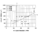
- FIG. 4 is a graph showing a part of the results shown in Table 1.
- the straight line Y indicates the minimum value of the relative movement speed (here, the conveyance speed of the glass substrate) of the laser light irradiation region where the precipitate is generated in the cooling process. In this case, 144 (m / hour) )Met.
- the A evaluation is distributed in a range surrounded by the straight line X and the straight line Y.
- the C evaluation is performed, and when the transport speed is slower than the straight line Y, the B evaluation is performed. It has become.
- the glass substrate in the laser light irradiation area This is considered to be because the laser beam irradiation part from one surface of the glass to the other surface can be reliably heated to a temperature higher than the temperature at which the glass vaporizes.
- the peripheral part of the laser light irradiation part after laser light irradiation can be sufficiently cooled and removed from the cut surface part as a precipitate, so that the cut surface with uniform surface characteristics. It is thought that it can be.
- the glass substrate that has been evaluated as C sufficient energy of the laser beam cannot be imparted with respect to the relative movement speed of the irradiation region of the laser beam with respect to the glass substrate (the conveyance speed of the glass substrate).
- the region it is considered that the other surface of the glass substrate could not be heated to a temperature higher than the temperature at which the glass vaporizes (the temperature could not be sufficiently raised in the entire range in the thickness direction of the glass substrate). For this reason, it is estimated that the glass substrate could not be cut.
- the relative movement speed of the laser light irradiation area with respect to the glass substrate is not sufficient, and the cooling speed of the peripheral part of the laser light irradiation part after laser light irradiation becomes slow, and the peripheral part is deposited. It is assumed that the cut surface did not become uniform because it was not excluded as a product. Or, when the temperature of the peripheral part of the laser light irradiation part after laser light irradiation is cooled by transporting the glass substrate, it is not the desired cooling rate, so that the cut surface and its periphery are cracked It is inferred.
- the energy density of the laser light can be appropriately selected for the A-evaluated glass substrate in accordance with the relative movement speed (glass substrate transport speed) of the laser light irradiation region with respect to the glass substrate. For this reason, it is considered that the laser beam irradiation region is heated from one surface of the glass substrate to the other surface at a temperature higher than the temperature at which the glass is vaporized. Furthermore, since the conveyance speed of the glass substrate is appropriate, the peripheral part of the laser light irradiation part after the laser light irradiation is cooled at an appropriate cooling rate, and the peripheral part of the laser light irradiation part after the laser light irradiation is a precipitate.
- FIG. 5 is a graph of the results in Table 2.
- the straight line Y indicates the minimum value of the relative movement speed (here, the conveyance speed of the glass substrate) of the irradiation region of the laser beam, in which the precipitate is generated in the cooling process, and in this case, 144 (m / hour) )Met.
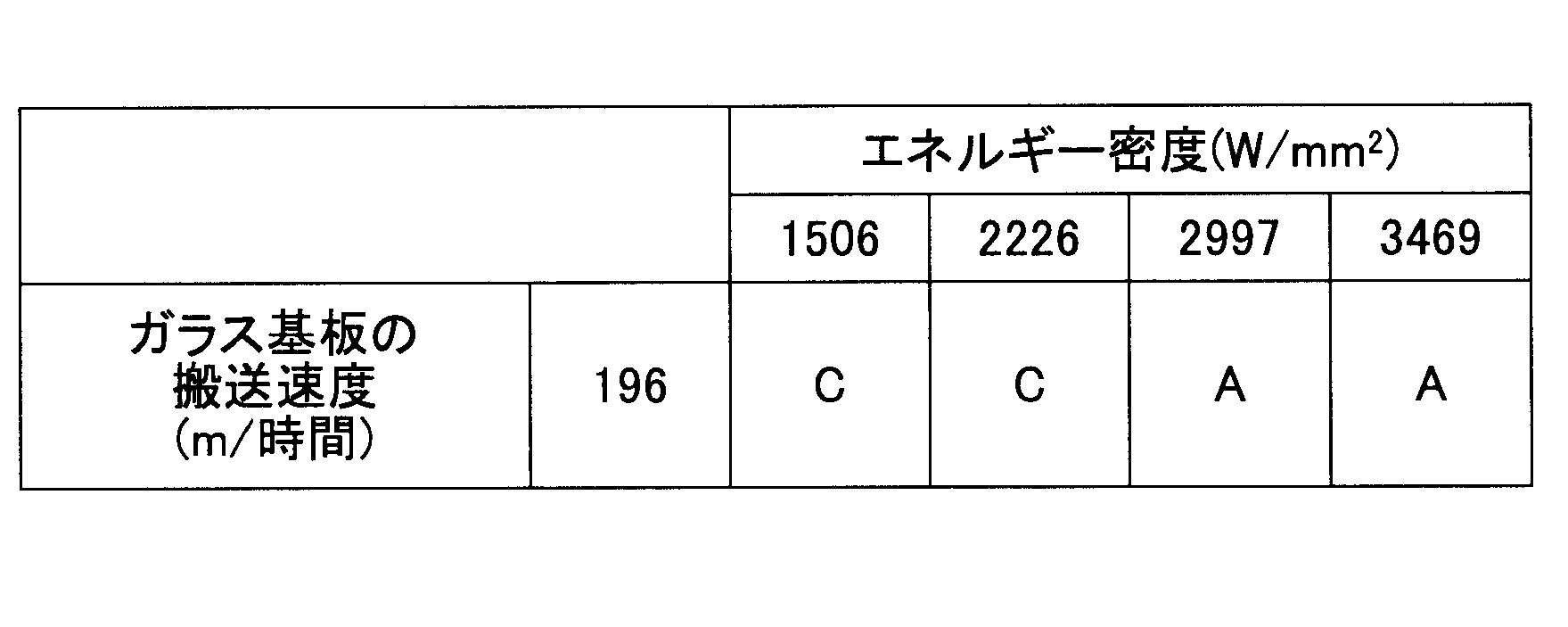
- FIG. 3 In this experimental example, the energy density of the laser beam and the relative movement speed of the irradiation region of the laser beam with respect to the glass substrate are changed in the same manner as in Experimental Example 1 except that the thickness of the glass substrate to be cut is 0.3 mm. Then, the glass substrate was cut, and the cut surface of the glass substrate after cutting was evaluated.
- FIG. 6 is a graph of the results in Table 3.
- the straight line Y indicates the minimum value of the relative movement speed (here, the conveyance speed of the glass substrate) of the irradiation region of the laser beam, in which the precipitate is generated in the cooling process, and in this case, 144 (m / hour) )Met.
- the glass substrate is cut by changing the energy density of the laser beam to be irradiated without changing the conveyance speed of the glass substrate.
- the energy density of the laser beam is increased to be higher than the straight line X
- the glass is vaporized in the laser beam irradiation area from one surface of the glass substrate to the other surface in the laser beam irradiation region. It was possible to heat to a temperature higher than the temperature to be evaluated, and it was confirmed that the evaluation was A.
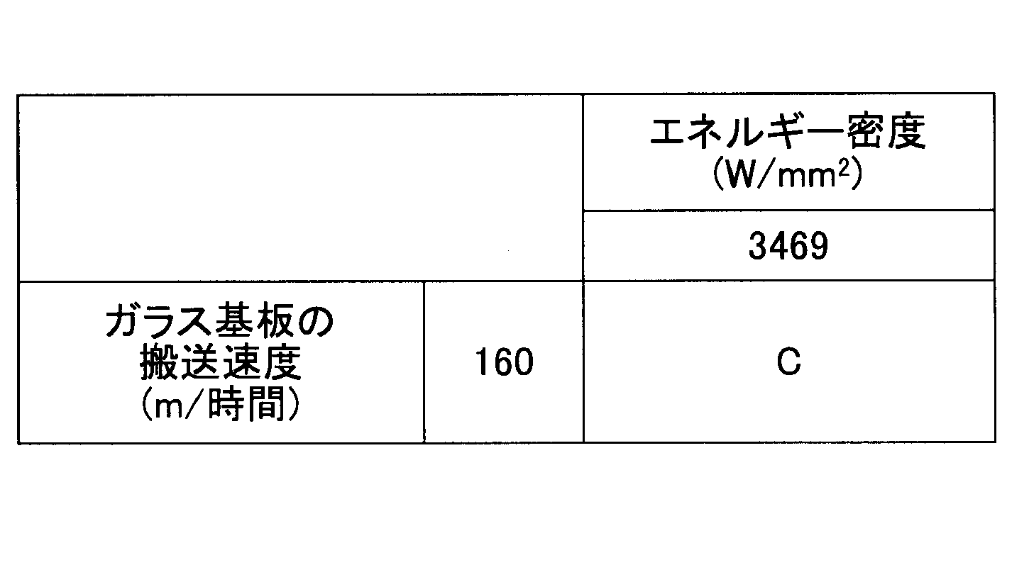
- Example 4 In this experimental example, the energy density of the laser beam and the relative movement speed of the irradiation region of the laser beam with respect to the glass substrate are changed in the same manner as in Experimental Example 1 except that the thickness of the glass substrate to be cut is 0.6 mm. Then, the glass substrate was cut, and the cut surface of the glass substrate after cutting was evaluated.
- FIG. 7 is a graph of the results in Table 4.
- the straight line Y indicates the minimum value of the relative movement speed (here, the conveyance speed of the glass substrate) of the irradiation region of the laser beam, in which the precipitate is generated in the cooling process, and in this case, 144 (m / hour) )Met.
- the energy density of the laser beam irradiated was lower than that of the straight line X. For this reason, sufficient energy of the laser beam cannot be applied to the relative movement speed of the laser beam irradiation area with respect to the glass substrate (the conveyance speed of the glass substrate), and the other surface of the glass substrate with respect to the laser light irradiation area It is considered that the glass substrate could not be heated to a temperature higher than the temperature at which it vaporizes. Therefore, it was considered that C evaluation was made because the glass substrate could not be cut.
- the present invention can be used in various glass substrate cutting methods, various glass substrate manufacturing methods, and the like.
Landscapes
- Engineering & Computer Science (AREA)
- Physics & Mathematics (AREA)
- Optics & Photonics (AREA)
- Plasma & Fusion (AREA)
- Mechanical Engineering (AREA)
- Chemical & Material Sciences (AREA)
- Laser Beam Processing (AREA)
- Re-Forming, After-Treatment, Cutting And Transporting Of Glass Products (AREA)
- Health & Medical Sciences (AREA)
- Toxicology (AREA)
- Thermal Sciences (AREA)
- Materials Engineering (AREA)
- Organic Chemistry (AREA)
Abstract
Description
E≧50×t×v
の関係を満たすように照射するレーザ光のエネルギー密度を調整することが好ましい。
[実験例1]
本実験例では、レーザ光のエネルギー密度、レーザ光の照射領域のガラス基板に対する相対移動速度を変化させてガラス基板を切断し、切断後のガラス基板の切断面について評価を行った。

[実験例2]
本実験例では、切断を行うガラス基板の板厚を0.2mmとした以外は、実験例1と同様にして、レーザ光のエネルギー密度、レーザ光の照射領域のガラス基板に対する相対移動速度を変化させてガラス基板を切断し、切断後のガラス基板の切断面について評価を行った。

[実験例3]
本実験例では、切断を行うガラス基板の板厚を0.3mmとした以外は、実験例1と同様にして、レーザ光のエネルギー密度、レーザ光の照射領域のガラス基板に対する相対移動速度を変化させてガラス基板を切断し、切断後のガラス基板の切断面について評価を行った。
[実験例4]
本実験例では、切断を行うガラス基板の板厚を0.6mmとした以外は、実験例1と同様にして、レーザ光のエネルギー密度、レーザ光の照射領域のガラス基板に対する相対移動速度を変化させてガラス基板を切断し、切断後のガラス基板の切断面について評価を行った。
12 レーザ光
21 レーザ光照射部
22 レーザ光照射部の周辺部
31 析出物
Claims (7)
- レーザ光を照射してガラス基板を切断するガラス基板の切断方法であって、
前記ガラス基板の一方の表面に前記レーザ光を照射したレーザ光の照射領域において、前記ガラス基板の一方の表面から他方の表面までのレーザ光照射部が気化する温度以上に加熱し、
前記レーザ光の照射領域を前記ガラス基板の切断予定線に沿って、前記ガラス基板に対して相対的に移動させることを特徴とするガラス基板の切断方法。 - 前記レーザ光照射部の周辺部は、前記レーザ光照射部の加熱後、ガラス転移温度以下までに冷却される請求項1に記載のガラス基板の切断方法。
- 前記レーザ光の照射領域のガラス基板に対する相対移動速度をv(m/時間)、前記レーザ光のエネルギー密度をE(W/mm2)、ガラス基板の板厚をt(mm)とした場合に、
E≧50×t×v
の関係を満たす請求項1または2記載のガラス基板の切断方法。 - 気化した前記レーザ光照射部のガラス成分を除去する請求項1乃至3いずれか一項に記載のガラス基板の切断方法。
- 前記レーザ光照射部の周辺部に発生した析出物を除去する請求項1乃至4いずれか一項に記載のガラス基板の切断方法。
- 前記ガラス基板の板厚は、3.0mm以下である請求項1乃至5いずれか一項に記載のガラス基板の切断方法
- 請求項1乃至6いずれか一項に記載のガラス基板の切断方法を用いたガラス基板の製造方法。
Priority Applications (3)
| Application Number | Priority Date | Filing Date | Title |
|---|---|---|---|
| JP2014522495A JP6206406B2 (ja) | 2012-06-28 | 2013-05-31 | ガラス基板の切断方法及びガラス基板の製造方法 |
| KR20147034251A KR20150035577A (ko) | 2012-06-28 | 2013-05-31 | 유리 기판의 절단 방법 및 유리 기판의 제조 방법 |
| CN201380030915.0A CN104364208B (zh) | 2012-06-28 | 2013-05-31 | 玻璃基板的切割方法及玻璃基板的制造方法 |
Applications Claiming Priority (4)
| Application Number | Priority Date | Filing Date | Title |
|---|---|---|---|
| JP2012-145991 | 2012-06-28 | ||
| JP2012145991 | 2012-06-28 | ||
| JP2013004667 | 2013-01-15 | ||
| JP2013-004667 | 2013-01-15 |
Publications (1)
| Publication Number | Publication Date |
|---|---|
| WO2014002685A1 true WO2014002685A1 (ja) | 2014-01-03 |
Family
ID=49782852
Family Applications (1)
| Application Number | Title | Priority Date | Filing Date |
|---|---|---|---|
| PCT/JP2013/065194 Ceased WO2014002685A1 (ja) | 2012-06-28 | 2013-05-31 | ガラス基板の切断方法及びガラス基板の製造方法 |
Country Status (5)
| Country | Link |
|---|---|
| JP (1) | JP6206406B2 (ja) |
| KR (1) | KR20150035577A (ja) |
| CN (1) | CN104364208B (ja) |
| TW (1) | TWI603801B (ja) |
| WO (1) | WO2014002685A1 (ja) |
Cited By (5)
| Publication number | Priority date | Publication date | Assignee | Title |
|---|---|---|---|---|
| WO2017208676A1 (ja) * | 2016-05-31 | 2017-12-07 | 日本電気硝子株式会社 | ガラスロールの製造方法 |
| WO2018030097A1 (ja) * | 2016-08-08 | 2018-02-15 | 日本電気硝子株式会社 | 帯状ガラスフィルムの切断方法 |
| WO2018147111A1 (ja) * | 2017-02-07 | 2018-08-16 | 日本電気硝子株式会社 | ガラスフィルムの製造方法 |
| KR20200035369A (ko) | 2017-07-31 | 2020-04-03 | 니폰 덴키 가라스 가부시키가이샤 | 유리 필름의 제조 방법 |
| WO2024042887A1 (ja) * | 2022-08-25 | 2024-02-29 | 日本電気硝子株式会社 | ガラス板の製造方法 |
Families Citing this family (1)
| Publication number | Priority date | Publication date | Assignee | Title |
|---|---|---|---|---|
| CN113953673B (zh) * | 2020-12-21 | 2025-02-21 | 宁夏小牛自动化设备股份有限公司 | 一种划裂太阳能电池片的方法及其划裂设备 |
Citations (3)
| Publication number | Priority date | Publication date | Assignee | Title |
|---|---|---|---|---|
| JPS57209838A (en) * | 1981-04-01 | 1982-12-23 | Kurieiteibu Gurasuwaakusu Inte | Laser glass cutting method and product made thereby |
| WO2006070825A1 (ja) * | 2004-12-28 | 2006-07-06 | Mitsuboshi Diamond Industrial Co., Ltd. | 脆性材料基板の分断方法および基板分断システム |
| JP2008247038A (ja) * | 2008-05-24 | 2008-10-16 | Lemi Ltd | 脆性材料のフルカット割断方法 |
Family Cites Families (1)
| Publication number | Priority date | Publication date | Assignee | Title |
|---|---|---|---|---|
| JP2000263277A (ja) * | 1999-03-16 | 2000-09-26 | Hitachi Cable Ltd | 非金属材料の加工方法及びその装置 |
-
2013
- 2013-05-31 CN CN201380030915.0A patent/CN104364208B/zh not_active Expired - Fee Related
- 2013-05-31 KR KR20147034251A patent/KR20150035577A/ko not_active Ceased
- 2013-05-31 WO PCT/JP2013/065194 patent/WO2014002685A1/ja not_active Ceased
- 2013-05-31 JP JP2014522495A patent/JP6206406B2/ja not_active Expired - Fee Related
- 2013-06-07 TW TW102120419A patent/TWI603801B/zh not_active IP Right Cessation
Patent Citations (3)
| Publication number | Priority date | Publication date | Assignee | Title |
|---|---|---|---|---|
| JPS57209838A (en) * | 1981-04-01 | 1982-12-23 | Kurieiteibu Gurasuwaakusu Inte | Laser glass cutting method and product made thereby |
| WO2006070825A1 (ja) * | 2004-12-28 | 2006-07-06 | Mitsuboshi Diamond Industrial Co., Ltd. | 脆性材料基板の分断方法および基板分断システム |
| JP2008247038A (ja) * | 2008-05-24 | 2008-10-16 | Lemi Ltd | 脆性材料のフルカット割断方法 |
Cited By (12)
| Publication number | Priority date | Publication date | Assignee | Title |
|---|---|---|---|---|
| WO2017208676A1 (ja) * | 2016-05-31 | 2017-12-07 | 日本電気硝子株式会社 | ガラスロールの製造方法 |
| JP2017214240A (ja) * | 2016-05-31 | 2017-12-07 | 日本電気硝子株式会社 | ガラスロールの製造方法 |
| TWI713736B (zh) * | 2016-05-31 | 2020-12-21 | 日商日本電氣硝子股份有限公司 | 玻璃捲筒的製造方法 |
| WO2018030097A1 (ja) * | 2016-08-08 | 2018-02-15 | 日本電気硝子株式会社 | 帯状ガラスフィルムの切断方法 |
| WO2018147111A1 (ja) * | 2017-02-07 | 2018-08-16 | 日本電気硝子株式会社 | ガラスフィルムの製造方法 |
| KR20190111896A (ko) | 2017-02-07 | 2019-10-02 | 니폰 덴키 가라스 가부시키가이샤 | 유리 필름의 제조 방법 |
| JPWO2018147111A1 (ja) * | 2017-02-07 | 2019-11-21 | 日本電気硝子株式会社 | ガラスフィルムの製造方法 |
| TWI729265B (zh) * | 2017-02-07 | 2021-06-01 | 日商日本電氣硝子股份有限公司 | 玻璃膜之製造方法 |
| KR102410719B1 (ko) | 2017-02-07 | 2022-06-20 | 니폰 덴키 가라스 가부시키가이샤 | 유리 필름의 제조 방법 |
| US11459264B2 (en) | 2017-02-07 | 2022-10-04 | Nippon Electric Glass Co., Ltd. | Method for producing glass film |
| KR20200035369A (ko) | 2017-07-31 | 2020-04-03 | 니폰 덴키 가라스 가부시키가이샤 | 유리 필름의 제조 방법 |
| WO2024042887A1 (ja) * | 2022-08-25 | 2024-02-29 | 日本電気硝子株式会社 | ガラス板の製造方法 |
Also Published As
| Publication number | Publication date |
|---|---|
| CN104364208B (zh) | 2017-12-12 |
| KR20150035577A (ko) | 2015-04-06 |
| TWI603801B (zh) | 2017-11-01 |
| JPWO2014002685A1 (ja) | 2016-05-30 |
| CN104364208A (zh) | 2015-02-18 |
| JP6206406B2 (ja) | 2017-10-04 |
| TW201404516A (zh) | 2014-02-01 |
Similar Documents
| Publication | Publication Date | Title |
|---|---|---|
| JP6379392B2 (ja) | ガラス基板の切断方法及びガラス基板の製造方法 | |
| JP6206406B2 (ja) | ガラス基板の切断方法及びガラス基板の製造方法 | |
| KR100849696B1 (ko) | 취성재료의 스크라이브 방법 및 스크라이브 장치 | |
| TW201350389A (zh) | 用於分離強化玻璃之方法及裝置及由該強化玻璃生產之物品 | |
| TWI637922B (zh) | 玻璃基板之倒角方法及雷射加工裝置 | |
| WO2007094160A1 (ja) | ガラス基板の面取り方法および装置 | |
| CN103608146B (zh) | 玻璃板切断方法 | |
| JP5987829B2 (ja) | 板ガラスの製造方法、および、その製造装置 | |
| CN103282317B (zh) | 脆性材料基板的割断方法 | |
| CN116568644B (zh) | 陶瓷切割方法及装置 | |
| JPWO2004002705A1 (ja) | 脆性材料基板のスクライブ装置及びスクライブ方法 | |
| TW201736123A (zh) | 強化溢流模內塗布玻璃板裝置及方法 | |
| JP2004035315A (ja) | 脆性材料基板の分断方法および脆性材料基板分断装置 | |
| JP5825551B2 (ja) | ガラス板切断方法およびガラス板切断装置 | |
| JP2014177369A (ja) | 強化ガラス部材の製造方法 | |
| WO2012014815A1 (ja) | 半導体チップ実装用のガラス基板へのアブレーション加工の方法 | |
| JP5884691B2 (ja) | ガラス板切断方法 | |
| JP5292420B2 (ja) | ガラス基板のスクライブ方法 | |
| WO2019138990A1 (ja) | ガラス物品の製造方法及び製造装置並びにガラス物品 | |
| CN110581049B (zh) | 处理基板边缘缺陷的等离子体系统及方法 | |
| CN106029317A (zh) | 脆性材料基板的切断方法及脆性材料基板的切断装置 | |
| KR20240081390A (ko) | 플라즈마 처리된 에지를 갖는 유리 물품, 플라즈마로 에지를 처리하는 방법 및 이 방법을 수행하는 시스템 | |
| TW201446451A (zh) | 用於切割非金屬基材之裝置及方法 | |
| JP2012236747A (ja) | 薄膜ガラスの端面処理方法、薄膜ガラス、及び薄膜ガラスの端面処理装置 | |
| CN121889352A (zh) | 玻璃物品的制造方法以及玻璃物品 |
Legal Events
| Date | Code | Title | Description |
|---|---|---|---|
| 121 | Ep: the epo has been informed by wipo that ep was designated in this application |
Ref document number: 13810649 Country of ref document: EP Kind code of ref document: A1 |
|
| ENP | Entry into the national phase |
Ref document number: 2014522495 Country of ref document: JP Kind code of ref document: A |
|
| ENP | Entry into the national phase |
Ref document number: 20147034251 Country of ref document: KR Kind code of ref document: A |
|
| NENP | Non-entry into the national phase |
Ref country code: DE |
|
| 122 | Ep: pct application non-entry in european phase |
Ref document number: 13810649 Country of ref document: EP Kind code of ref document: A1 |