WO2014002184A1 - 設備管理システム及びプログラム - Google Patents
設備管理システム及びプログラム Download PDFInfo
- Publication number
- WO2014002184A1 WO2014002184A1 PCT/JP2012/066248 JP2012066248W WO2014002184A1 WO 2014002184 A1 WO2014002184 A1 WO 2014002184A1 JP 2012066248 W JP2012066248 W JP 2012066248W WO 2014002184 A1 WO2014002184 A1 WO 2014002184A1
- Authority
- WO
- WIPO (PCT)
- Prior art keywords
- equipment
- facility
- data
- unit
- management
- Prior art date
Links
Images


Classifications
-
- G—PHYSICS
- G06—COMPUTING; CALCULATING OR COUNTING
- G06F—ELECTRIC DIGITAL DATA PROCESSING
- G06F13/00—Interconnection of, or transfer of information or other signals between, memories, input/output devices or central processing units
- G06F13/10—Program control for peripheral devices
- G06F13/102—Program control for peripheral devices where the programme performs an interfacing function, e.g. device driver
-
- H—ELECTRICITY
- H04—ELECTRIC COMMUNICATION TECHNIQUE
- H04L—TRANSMISSION OF DIGITAL INFORMATION, e.g. TELEGRAPHIC COMMUNICATION
- H04L43/00—Arrangements for monitoring or testing data switching networks
- H04L43/08—Monitoring or testing based on specific metrics, e.g. QoS, energy consumption or environmental parameters
-
- G—PHYSICS
- G06—COMPUTING; CALCULATING OR COUNTING
- G06Q—INFORMATION AND COMMUNICATION TECHNOLOGY [ICT] SPECIALLY ADAPTED FOR ADMINISTRATIVE, COMMERCIAL, FINANCIAL, MANAGERIAL OR SUPERVISORY PURPOSES; SYSTEMS OR METHODS SPECIALLY ADAPTED FOR ADMINISTRATIVE, COMMERCIAL, FINANCIAL, MANAGERIAL OR SUPERVISORY PURPOSES, NOT OTHERWISE PROVIDED FOR
- G06Q10/00—Administration; Management
- G06Q10/06—Resources, workflows, human or project management; Enterprise or organisation planning; Enterprise or organisation modelling
- G06Q10/063—Operations research, analysis or management
- G06Q10/0639—Performance analysis of employees; Performance analysis of enterprise or organisation operations
-
- G—PHYSICS
- G06—COMPUTING; CALCULATING OR COUNTING
- G06F—ELECTRIC DIGITAL DATA PROCESSING
- G06F11/00—Error detection; Error correction; Monitoring
- G06F11/30—Monitoring
- G06F11/3003—Monitoring arrangements specially adapted to the computing system or computing system component being monitored
- G06F11/3013—Monitoring arrangements specially adapted to the computing system or computing system component being monitored where the computing system is an embedded system, i.e. a combination of hardware and software dedicated to perform a certain function in mobile devices, printers, automotive or aircraft systems
-
- G—PHYSICS
- G06—COMPUTING; CALCULATING OR COUNTING
- G06F—ELECTRIC DIGITAL DATA PROCESSING
- G06F11/00—Error detection; Error correction; Monitoring
- G06F11/30—Monitoring
- G06F11/3055—Monitoring arrangements for monitoring the status of the computing system or of the computing system component, e.g. monitoring if the computing system is on, off, available, not available
-
- G—PHYSICS
- G06—COMPUTING; CALCULATING OR COUNTING
- G06F—ELECTRIC DIGITAL DATA PROCESSING
- G06F11/00—Error detection; Error correction; Monitoring
- G06F11/30—Monitoring
- G06F11/3065—Monitoring arrangements determined by the means or processing involved in reporting the monitored data
-
- H—ELECTRICITY
- H04—ELECTRIC COMMUNICATION TECHNIQUE
- H04L—TRANSMISSION OF DIGITAL INFORMATION, e.g. TELEGRAPHIC COMMUNICATION
- H04L43/00—Arrangements for monitoring or testing data switching networks
- H04L43/04—Processing captured monitoring data, e.g. for logfile generation
- H04L43/045—Processing captured monitoring data, e.g. for logfile generation for graphical visualisation of monitoring data
-
- H—ELECTRICITY
- H04—ELECTRIC COMMUNICATION TECHNIQUE
- H04L—TRANSMISSION OF DIGITAL INFORMATION, e.g. TELEGRAPHIC COMMUNICATION
- H04L61/00—Network arrangements, protocols or services for addressing or naming
-
- H—ELECTRICITY
- H04—ELECTRIC COMMUNICATION TECHNIQUE
- H04L—TRANSMISSION OF DIGITAL INFORMATION, e.g. TELEGRAPHIC COMMUNICATION
- H04L61/00—Network arrangements, protocols or services for addressing or naming
- H04L61/45—Network directories; Name-to-address mapping
-
- H—ELECTRICITY
- H04—ELECTRIC COMMUNICATION TECHNIQUE
- H04L—TRANSMISSION OF DIGITAL INFORMATION, e.g. TELEGRAPHIC COMMUNICATION
- H04L67/00—Network arrangements or protocols for supporting network services or applications
- H04L67/50—Network services
- H04L67/56—Provisioning of proxy services
Definitions
- This invention relates to an equipment management system and a program.
- This facility management apparatus includes a Web server.
- the Web server generates a Web page for browsing information related to the state of the equipment device.
- the generated web page is displayed on the screen of the personal computer by the web browser of the personal computer. By browsing this web page, the state of the equipment can be monitored.
- a display device for a home equipment monitoring system that can simultaneously display information of a plurality of Web servers on a Web browser is disclosed (for example, see Patent Document 1).
- the center-side Web content sent from the center device and the local-side Web content sent from the controller can be simultaneously displayed on one screen of the display unit. This facilitates comparison between the Web content sent from the center apparatus and the Web content sent from the controller.
- the screen of the Web browser is divided into a plurality of areas. And each area
- Patent Document 1 it is difficult to use the technology described in Patent Document 1 in an equipment management system in which the number of equipment management devices varies depending on the number of building equipment and the system configuration.
- the present invention has been made in view of the above circumstances, and even when an unspecified number of equipment management devices are installed, the status of equipment managed by a plurality of equipment management devices is monitored on the same Web browser screen.
- An object of the present invention is to provide an equipment management system and program that can be used.
- the facility management system of the present invention provides: An equipment management system for managing equipment using a plurality of equipment management devices, An equipment management unit provided in each equipment management device for managing connected equipment; A web server unit capable of providing web content including a monitoring program for monitoring the status of the equipment managed by the plurality of equipment management devices; An address holding unit that is provided in each of the equipment management devices and holds address information of the plurality of equipment management devices; The Web content sent from the Web server unit is acquired, the monitoring program is executed, the address information held in the address holding unit is acquired, and the plurality of facilities are acquired using the acquired address information.
- Connect to each management device to obtain information on the status of the equipment managed by each of the equipment management devices, and the status of the equipment managed by the plurality of equipment management devices on one screen of a Web browser A web browser section that displays information about Is provided.
- the monitoring program included in the Web content read by the Web browser is executed by the Web browser unit, thereby acquiring the address information of each of the plurality of facility management apparatuses, and using the address information, each facility is acquired. Acquire the status of the equipment managed by the management device. Since the monitoring program is executed by the Web browser, the acquired equipment data can be displayed on the same screen of the Web browser as that of the same Web page. As a result, even when an unspecified number of equipment management devices are installed, the status of the equipment managed by a plurality of equipment management devices can be monitored on the same Web browser screen.
- Embodiment 1 FIG. First, a first embodiment of the present invention will be described.
- FIG. 1 shows the configuration of an equipment management system 1 according to Embodiment 1 of the present invention.
- the facility management system 1 according to this embodiment includes a plurality of facility devices 2, a plurality of facility management devices 3, and a monitoring terminal 4.
- the equipment management system 1 is a system that manages equipment equipment 2 using a plurality of equipment management devices 3.
- Each facility device 2 and facility management device 3 are connected to each other via a dedicated communication line 5 so as to communicate with each other.
- the plurality of facility management apparatuses 3 and the monitoring terminal 4 are connected to each other via a communication line 6 so as to communicate with each other.
- the equipment 2 is assumed to be various equipment installed in the building, such as air conditioning equipment, lighting equipment, and hot water supply equipment.
- the plurality of facility devices 2 are respectively installed at designated locations in a house such as a building.
- Each facility device 2 operates under the management of the facility management device 3.
- the state of each facility device 2 (for example, the operation state) is notified to the facility management device 3 via the dedicated communication line 5.
- the group of the some installation apparatus 2 managed by the same installation management apparatus 3 is also called the installation apparatus group 7 below.
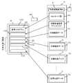
- FIG. 2 shows the configuration of the facility management apparatus 3.
- the facility management device 3 comprehensively manages (monitors and controls) a plurality of connected facility devices 2, that is, the facility device group 7. As shown in FIG. 2, the facility management apparatus 3 includes a display device 10, an input device 20, a control unit 30, a data management unit 40, a facility device communication management unit 50, and a monitoring terminal communication management unit 60.
- the display device 10 displays various screens for managing the equipment group 7 under the control of the control unit 30.
- the input device 20 is an input device such as a mouse, a keyboard, or a touch panel.
- the input device 20 is installed on the display device 10.
- the administrator operates the input device 20 such as a mouse, the screen can be switched and the connected equipment 2 can be operated according to the input content.
- the control unit 30 is a computer and includes a CPU (Central Processing Unit), a memory, and a storage device (all not shown). When the CPU executes the program stored in the memory, the following components of the control unit 30 and their functions are realized.
- CPU Central Processing Unit
- memory volatile and non-volatile memory
- storage device non-volatile memory
- the control unit 30 holds the state of the equipment 2 (for example, the operation state) in the data management unit 40 and transmits / receives data necessary for the monitoring screen displayed on the monitoring terminal 4 to / from the monitoring terminal 4.
- the control unit 30 includes an equipment device management unit 31 and a Web server unit 32.
- the facility equipment management unit 31 is provided in each equipment management device 3 and manages the connected equipment 2. More specifically, the facility device management unit 31 monitors and controls the state of the facility device 2. That is, the state of the facility device 2 includes, for example, an operation state such as an operation state / stop state or an abnormal state of the facility device 2.
- the web server unit 32 is provided in each facility management device 3.
- the web server unit 32 is a server that can provide web content 80 to be described later.
- the Web content 80 includes a monitoring program 82 for monitoring the state of the equipment 2 managed by the plurality of equipment management apparatuses 3.
- the Web server unit 32 transmits the Web content 80 managed by the data management unit 40 to the monitoring terminal 4 in response to a request from the monitoring terminal 4.
- the Web server unit 32 includes an equipment data communication unit 33 and a system configuration data communication unit 34.
- the equipment data communication unit 33 sets and monitors equipment data.
- the equipment data communication unit 33 notifies the monitoring terminal 4 of information related to a change in the state of the equipment device when the state of the equipment device 2 managed by the equipment management device 2 changes. Specifically, the updated equipment data 70 is transmitted.
- the system configuration data communication unit 34 sets and monitors the equipment management device address list 91 in which address information of all equipment management devices 3 in the equipment management system 1 is held.
- the facility management device address list 91 will be described later.
- the data management unit 40 is a computer and includes a CPU (Central Processing Unit), a memory, and a storage device (all not shown). When the CPU executes a program stored in the memory, the following components of the data management unit 40 and their functions are realized.
- CPU Central Processing Unit
- memory volatile and non-volatile memory
- storage device all not shown.
- the data management unit 40 manages various data necessary for monitoring the equipment group 7 and various data for displaying the monitoring screen of the equipment 2 on the monitoring terminal 4.
- the data managed by the data management unit 40 is roughly classified into equipment device data 70, Web content 80, and system configuration data 90.
- the equipment data 70 includes connection information 71 of each equipment 2, operation state data 72, and display position data 73 on the floor plan view of equipment icons.
- connection information 71 is data necessary for connection to the equipment group 7 such as the address number, operation group number, and model identification information of each equipment 2 managed by the equipment management apparatus 3.
- the operation state data 72 is information on the current operation state of each facility device 2 (for example, in the case of an air conditioner, the operation / stop state, the operation mode such as cooling or heating, the set temperature, the room temperature, the error occurrence state) Corresponding data.
- the operation state data 72 is updated to the latest state at any time by data transmission / reception with each facility device 2.
- the data management unit 40 that monitors the driving state data 72 corresponds to the driving state data holding unit.
- the display position data 73 is data indicating the floor number where each equipment device 2 is installed and the X and Y coordinates on the plan view of each installed device 2.
- the display position data 73 is used when the icon of the equipment device 2 is arranged on the floor plan view displayed on the equipment device monitoring screen of the monitoring terminal 4 described later. That is, the display position data 73 is data indicating the display positions of the plurality of facility devices 2 on the floor plan view.
- the data management unit 40 corresponds to a display position data holding unit.
- additional information such as a building number may be added to the display position data 73 in addition to the floor number.
- the X coordinate and the Y coordinate may be indicated by a ratio (0 to 100%) with respect to the vertical and horizontal sizes of the plan view.
- the position information for displaying the equipment icon may be changed following the display.
- the Web content 80 includes a screen configuration file 81, a monitoring program 82, and a floor plan file 83.
- the screen configuration file 81 describes the layout configuration of the screen (Web browser screen) displayed on the monitoring terminal 4.
- the monitoring program 82 is a program that is executed on a Web browser and performs various communication processes and screen display processes.
- the monitoring program 82 is a program for monitoring the state of the equipment 2 managed by the plurality of equipment management apparatuses 3.
- the floor plan file 83 is data of a plan view of the floor of the building that is the background of the monitoring screen.
- the screen configuration file 81 includes a file that defines the layout configuration of the screen displayed on the monitoring terminal 4 and various image files that are arranged on the screen according to the layout configuration.
- the screen configuration file 81 includes an HTML (HyperText Markup language) file describing the frame configuration, and various image files described in GIF (Graphics Interchange Format) format, JPEG (Joint Photographic Experts Group) format, BMP (Bitmap) format, etc. It is.
- the monitoring program 82 is a program that can be executed on a Web browser.
- the monitoring program 82 is described in a language such as a JAVA (registered trademark) script.
- the monitoring program 82 is a program for communicating with each facility management device 3 to collect necessary data and displaying a monitoring screen.
- the monitoring program 82 is embedded in the screen configuration file 81, and is executed when the Web browser executes the screen configuration file 81.
- the floor plan file 83 is an image for displaying the floor layout as the background of the monitoring screen so that the installation position of the equipment 2 in the building can be grasped.
- a floor plan image is stored in units of floors.
- the floor plan file 83 is plan view data showing an image of a plan view of an area where a plurality of facility devices 2 are installed.
- the data management unit 40 corresponds to a plan view data holding unit.
- the system configuration data 90 is data relating to the system configuration of the equipment management system 1.
- the system configuration data 90 includes an equipment management device address list 91.
- the facility management device address list 91 holds address information of connection destinations of the plurality of facility management devices 3.
- the data management unit 40 that manages the facility management device address list 91 corresponds to an address holding unit.
- the equipment communication management unit 50 is an interface of the dedicated communication line 5. Data is transmitted to and received from the equipment 2 via the equipment communication management unit 50.
- the dedicated communication line 5 does not necessarily have to be a dedicated communication line, and may be configured using a general-purpose communication line such as a LAN (Local Area Network) or an RS-485 interface.
- the monitoring terminal communication management unit 60 is an interface of the communication line 6. Data transmission / reception with the monitoring terminal 4 is performed via the monitoring terminal communication management unit 60.
- the communication line 6 is a communication line that can be connected to a personal computer, such as a LAN or a wireless LAN.
- FIG. 3 shows the configuration of the monitoring terminal 4.
- the monitoring terminal 4 is a terminal capable of executing a Web browser that runs on a general-purpose personal computer.
- the web browser of the monitoring terminal 4 receives the web content 80 from the control unit 30 (web server unit 32) of the facility management apparatus 3, and displays a monitoring screen according to the web content 80.
- the monitoring terminal 4 includes a display device 100, an input device 110, a web content display control unit 120, a database unit 130, and a monitoring terminal communication management unit 140.
- the display device 100 displays a web browser screen executed by the web content display control unit 120. More specifically, under the control of the Web content display control unit 120, the monitoring screen of the equipment device 2 is displayed on the screen on the Web browser according to the Web content 80 acquired from the equipment management apparatus 3.
- the input device 110 is an input device such as a mouse, a keyboard, or a touch panel.
- the input device 110 is installed on the display device 100.
- the administrator operates the input device 110 such as a mouse, the screen can be switched and the equipment 2 can be operated according to the input content.
- the web content display control unit 120 is a computer that can execute a web browser.
- the Web content display control unit 120 includes a CPU (Central Processing Unit), a memory, and a storage device (all not shown). When the CPU executes the program stored in the memory, the following components of the Web content display control unit 120 and their functions are realized.
- the web content display control unit 120 communicates with the connection destination facility management device 3 input from the input device 110 to acquire the web content 80 and displays the monitoring screen of the facility device group 7 on the display device 100. More specifically, the Web content display control unit 120 executes the monitoring program 82 to acquire information related to the state of the equipment 2 managed by each of the plurality of equipment management apparatuses 3 and to display a monitoring screen (Web browser). Screen).
- the Web content display control unit 120 includes a screen configuration file analysis unit 121 and a monitoring program execution unit 122.
- the screen configuration file analysis unit 121 analyzes the acquired screen configuration file 81.
- the monitoring program execution unit 122 acquires the Web content 80 downloaded from the facility management apparatus 3 and executes the monitoring program 82 to acquire information related to the state of the facility device 2 managed by each of the plurality of facility management apparatuses 3. To display.
- the monitoring program execution unit 122 executes the monitoring program 82 to acquire the facility management device address list 91 held by each facility management device 3, and uses the acquired facility management device address list 91. Then, by connecting to each of the plurality of facility management devices 3, the facility device data 70, which is information regarding the state of the plurality of facility devices 2 managed by the plurality of facility management devices 3, is acquired.
- the monitoring program execution unit 122 includes a data communication management unit 123 and an equipment data management unit 124.
- the data communication management unit 123 is connected to the facility management device 3, acquires various data from each facility management device 3, registers the acquired data in the database unit 130, and displays the data on the screen. For example, the data communication management unit 123 acquires the operation state data 72 from the plurality of facility management apparatuses 3 and displays the operation state data 72 on the screen of the Web browser. In addition, the data communication management unit 123 acquires the floor plan file 83 and the display position data 73 as the display position data 136, and a plurality of facility devices 2 at the positions indicated by the display position data 136 in the plan view image. Each icon is superimposed and displayed on the screen of the Web browser.
- the facility device data management unit 124 updates the facility device data 133 of the database unit 130 based on the data.
- the database unit 130 is a database that manages various data used by the monitoring program execution unit 122.
- the database unit 130 is a computer including a CPU (Central Processing Unit), a memory, and a storage device (all not shown). When the CPU executes a program stored in the memory, the following components of the database unit 130 and their functions are realized.
- the database unit 130 includes system configuration data 131 and facility equipment data 133.
- the system configuration data 131 is data relating to the system configuration of the facility management system 1.
- the system configuration data 131 includes an equipment management device address list 132.
- the equipment management device address list 132 is a list of equipment management device addresses, such as IP addresses and host names, which are specific information of a plurality of equipment management devices 3 as communication destinations.
- the facility equipment data 133 includes equipment equipment connection information 134, operating state data 135, and display position data 136.
- the equipment data 133 is always kept up-to-date by the equipment data management unit 124.
- the system configuration data 131 and the equipment data 133 in the database unit 130 correspond to the system configuration data 90 and the equipment data 70 in the data management unit 40 of the equipment management apparatus 3 shown in FIG.
- the monitoring terminal communication management unit 140 is an interface of the communication line 6. Data is transmitted to and received from the facility management apparatus 3 via the monitoring terminal communication management unit 140.
- FIG. 4 operations of the facility management device 3 and the monitoring terminal 4 will be described with reference to FIGS. 4, 5, 6 and 7.
- FIG. 4 processing when the URL of the facility management device 3 is input to the Web browser displayed on the display device 10 of the monitoring terminal 4 and the monitoring page of the facility device 2 is opened (monitoring screen display processing). The flow of is shown.
- the Web content display control unit 120 of the monitoring terminal 4 acquires the Web content 80 from the facility management apparatus 3 (step S101). More specifically, the Web content display control unit 120 starts connection to the equipment management apparatus 3 via the monitoring terminal communication management unit 140 using the HTTP protocol (Hypertext Transfer Protocol).
- the web server unit 32 of the facility management apparatus 3 permits connection via the monitoring terminal communication management unit 60 and transmits the requested web content 80 to the monitoring terminal 4.
- the monitoring terminal 4 displays a monitoring screen according to the acquired Web content 80 (step S102). More specifically, the Web content display control unit 120 analyzes the acquired Web content 80 by the screen configuration file analysis unit 121, and acquires an HTML file (screen configuration file 81) included in the Web content 80. . Subsequently, the Web content display control unit 120 displays a monitoring screen according to the acquired HTML file.
- the monitoring terminal 4 (Web content display control unit 120) executes the monitoring program 82 embedded in the HTML file (step S103).
- the monitoring program is described in JAVA (registered trademark) script.
- the data communication management unit 123 in the monitoring program execution unit 122 of the monitoring terminal 4 connects to the equipment management apparatus (representative equipment management apparatus) 3 that has acquired the web content 80 by the WebSocket method (step S104).
- the WebSocket method is a technical standard for bidirectional communication between a Web server and a Web client. Unlike the HTTP protocol, the WebSocket method can be always connected. For this reason, it becomes possible to start transmission from either the Web server or the Web client when communication is required. Thereby, it is possible to report to the other party in real time that there has been a change in the equipment 2 or the like due to an operation or a state change.
- the monitoring terminal 4 acquires the system configuration data 90 from the equipment management device 3 (step S105).
- the system configuration data 90 includes a facility management device address list 91 that is a list of address information such as the IP address and host name of the connected facility management device 3.
- the monitoring terminal 4 (data communication management unit 123) holds the acquired system configuration data 90 as the system configuration data 131 of the database unit 130 (step S106).
- the monitoring terminal 4 (data communication management unit 123) connects to any of the facility management apparatuses 3 by the WebSocket method (step S107).
- the monitoring terminal 4 data communication management unit 123 connects to any of the facility management apparatuses 3 by the WebSocket method (step S107).
- an IP address or host name included in the system configuration data 131 of the database unit 130 is used.
- the monitoring terminal 4 While connected by the WebSocket method, the monitoring terminal 4 (data communication management unit 123) acquires the connection information 71 of the equipment 2 and holds it as connection information 134 (step S108).
- the monitoring terminal 4 acquires the operation state data 72 of the equipment 2 and holds it as the operation state data 135 (step S109).
- the monitoring terminal 4 acquires the display position data 73 on the plan view and holds it as the display position data 136 (step S110).
- the equipment connection information 134, the equipment operating status data 135, and the display position data 136 on the plan view are stored as equipment data 133 in the database unit 130.
- the monitoring terminal 4 determines whether or not acquisition and retention of information of all devices is completed (step S111). If not completed (step S111; No), the monitoring terminal 4 (data communication management unit 123) returns to step S107.
- the monitoring terminal 4 (data communication management unit 123) repeats steps S107 ⁇ S108 ⁇ S109 ⁇ S110 ⁇ S111 until acquisition and retention of information of all devices is completed.
- the monitoring terminal 4 (data communication management unit 123) displays each equipment device 2 on the floor plan view displayed on the screen of the web browser.
- an equipment icon indicating an operation state is displayed (step S112).
- the monitoring screen display process is completed in the monitoring terminal 4, and the equipment device group 7 managed by the plurality of equipment management apparatuses 3 can be monitored on the same Web page of the same Web browser.
- the equipment management device 3 (facility equipment data communication unit 33) notifies the monitoring terminal 4 of the content of the change in the state.
- the monitoring terminal 4 holds the contents as the operation state data 135 or the display position data 136 of the equipment device data 133.
- the equipment data management unit 124 realized by the monitoring program execution unit 122 displays each equipment on the plan view on the Web screen.
- the display state of the equipment icon indicating the operation state is updated according to the display position data 136 of 2.
- FIG. 5 shows a communication procedure between the equipment management apparatus 3 and the monitoring terminal 4 in the monitoring screen display process shown in FIG.
- the monitoring terminal 4 acquires the Web content 80 from the representative facility management apparatus 3 (step S101), and acquires the system configuration data 90 from the representative facility management apparatus 3 (step S101).
- step S101 the representative facility management apparatus 3
- step S101 the representative facility management apparatus 3
- step S104, S105 the system configuration data 90 from the representative facility management apparatus 3
- the monitoring terminal 4 is connected to each facility management device 3 by the WebSocket method (step S107), and directly acquires the facility device data 70 from each facility management device 3 (steps S108 to S110). Thereby, decentralization of processing of the entire system is realized.
- FIG. 6 shows an example of the floor monitoring screen displayed on the monitoring terminal 4 by the monitoring screen display process.
- the facility management devices 3a, 3b, and 3c are installed on the same floor, and the facility device group 7 connected to each of them is a monitoring target.
- a floor plan view is displayed on one screen in the Web browser according to the display position data 136 acquired from each facility management device 3.
- an icon 200 is arranged according to the operation state data 135 of each equipment device 2 acquired from the plurality of equipment management devices 3a, 3b, 3c.
- the display state of each icon 200 represents the operation state of the corresponding equipment device 2.
- FIG. 7 shows an example of a screen that is displayed on the monitoring terminal 4 and displays a unit in which an abnormality has occurred.
- FIG. 7 in this example, according to the operation state data 135 of each equipment device 2 acquired from the equipment management devices 3a, 3b, and 3c, information about the equipment device 2 in which an abnormality has occurred They are displayed together on one screen of the browser.
- FIG. 8 shows a processing flow of the facility management apparatus 3 when the operation state of the facility device 2 changes.
- the equipment device management unit 31 of the equipment management device 3 receives a report from the equipment device 2. A change in the state of the equipment 2 is detected, and the operation state data 72 is updated (step S201).
- the control unit 30 of the facility management apparatus 3 determines whether or not there is a connection with the monitoring terminal 4 (whether or not there is a WebSocket connection) (step S202).
- the facility management apparatus 3 (facility device data communication unit 33) notifies a change in the operating state of the facility device 2 to the monitoring terminal 4 to which the WebSocket is connected (step).
- the facility management apparatus 3 (facility device data communication unit 33) transmits the operation state data 72 to the monitoring terminal 4. Thereafter, the facility management apparatus 3 ends the process.
- FIG. 9 shows a processing flow of the monitoring terminal 4 when a notification of a change in the operation state data 72 of the equipment device 2 is received from the equipment management device 3.
- the equipment data management unit 124 of the monitoring terminal 4 receives the received operation. Using the state data 72, the operation state data 135 in the equipment data 133 is updated (step S301).
- the equipment device data management unit 124 of the monitoring terminal 4 updates the currently displayed monitoring screen to the latest data (that is, the state in which the update of the operation state data 135 is reflected) (step S302).
- the monitoring terminal 4 terminates the process when the operating state of the equipment device 2 changes.
- the facility device group 7 managed by the plurality of facility management devices 3 can be constantly monitored, and the operation state data 135 can be always updated.
- the Web content 80 and the system configuration data 90 held by the facility management apparatus 3 can be set in the facility management apparatus 3 in advance.
- the settings of the Web content 80 and the system configuration data 90 may be set from the input device 20 of the facility management apparatus 3 or may be set from the Web browser of the monitoring terminal 4.
- the display position data 73 of each equipment device 2 may be set from the input device 20 of the equipment management device 3 in the same manner. In this case, the setting may be made while confirming the display position with the Web browser of the monitoring terminal 4.
- the facility management device 3 includes the display device 10 and the input device 20, but the display device 10 and the input device 20 are not necessarily required.
- the display device 10 and the input device 20 may be omitted, and settings, operations, and the like may be performed from the monitoring terminal 4 through communication via the communication line 7.
- the Web browser of the monitoring terminal 4 is used.
- the Web browser may be on the facility management apparatus 3.
- a web browser is activated on the representative facility management apparatus 3 to read the web content 80, and the processing procedure similar to that shown in FIG. 4 is executed, and the display apparatus 10 is connected to the other facility management apparatus 3.
- the equipment group 7 may be monitored together.
- a personal computer is used as the monitoring terminal 4, but it is not always necessary to use a personal computer.
- a dedicated terminal or a tablet terminal capable of operating the monitoring program 82 may be used.
- a text format using XML (eXtensible Markup Language) or the like can be adopted as a format of data communicated between the monitoring terminal 4 and the facility management apparatus 3.
- XML eXtensible Markup Language
- other formats such as a binary format may be used to reduce the communication size.
- you may encrypt communication so that communication information may be concealed.
- the WebSocket that can always be connected is used as the communication method.
- communication may be performed using an HTTP protocol or a unique protocol.
- the Web browser executes the monitoring program 82 included in the Web content 80 read by the Web browser (the Web content display control unit 102), whereby a plurality of monitoring programs 82 are executed.
- the state of the equipment 2 managed by each of the equipment management devices 3 is acquired. Since the monitoring program 82 is executed by the Web browser, the acquired equipment data can be displayed on the same screen of the Web browser as that of the same Web page.
- the monitoring program 82 included in the Web content 80 and executed by the Web browser is executed to connect to the plurality of equipment management apparatuses 3 and display the floor plan file 83 and the display.
- the position data 73 is acquired by the monitoring terminal 4. In this way, it is possible to simultaneously display the state of the equipment 2 managed by the plurality of equipment management apparatuses 3 on the plan view in the same Web page using the icon 200 or the like. As a result, conventionally, the states of the plurality of facility devices 2 on the same floor managed by different facility management apparatuses 3 can be simultaneously displayed on the same plan view.
- the equipment group 7 is managed by each equipment management device 3 in a distributed manner. Moreover, the monitoring terminal 4 acquires the state of the equipment group 7 managed by each of the equipment management apparatuses 3 other than the equipment management apparatus 3 that has read the web content by executing the monitoring program 82 using a web browser. . Thereby, since the load concerning the one equipment management apparatus 3 can be made small, the equipment management apparatus 3 can be manufactured with low-cost CPU with low performance.
- a TCP connection is connected from the client side (monitoring terminal 4 side) to the server side (facility management device 3), and the state of the facility device 2 is monitored. It was a mechanism to disconnect the connection. In such a mechanism, the client's address is not known to the server except during connection, so even if there is a change in the state of the equipment, it was not possible to report immediately.
- the facility management apparatus 3 is always connected using a WebSocket that can be used from a Web browser. Thereby, when the state of the equipment 2 is changed, the equipment management system 3 can notify the connected monitoring terminal 4. As a result, it is possible to always monitor the state of the latest equipment device 2 with a Web browser.
- the equipment management apparatus 3 often uses a built-in low-cost CPU. For this reason, depending on the performance of the CPU and the performance of memories such as ROM and RAM, the number of facility equipment groups 7 that can be managed by the facility management apparatus 3 is limited. For this reason, only the number managed by the facility management apparatus 3 could be monitored simultaneously on the same screen of the Web browser.
- the equipment management system 1 by using the equipment management system 1 according to this embodiment, the equipment device group 7 of the entire building managed by a large number of equipment management devices 3 using abundant CPUs and memories possessed by a personal computer can be converted into a Web browser. Can be monitored together on one screen.
- Embodiment 2 FIG. Next, a second embodiment of the present invention will be described.
- the equipment management system 1 and the equipment management apparatus 3 according to Embodiment 2 of the present invention have the same configuration as that used in Embodiment 1 shown in FIG. 1 and FIG.
- the Web content 80 and the system configuration data 90 that have been used only by the representative facility management apparatus 3 are also used by other representative facility management apparatuses 3.
- control unit 30 of each facility management device 3 transmits the changed data to another facility management device 3 when the data held therein changes.
- the control unit 30 corresponds to a data update unit.
- FIG. 10 shows setting data update processing when each data of the equipment management device address list 91 or the floor plan file 83 is updated for the representative equipment management device 3.
- the setting data update process is executed by the control unit 30.
- the equipment management device 3 (the control unit 30) performs data transfer according to the changed contents.
- the equipment management device address list 91 or the floor plan file 83 in the management unit 40 is updated (step S401).
- the equipment management device 3 (control unit 30) reads the equipment management device address list 91 (step S402), and performs the subsequent processing on all the equipment management devices 3 in the list.
- the facility management apparatus 3 (control unit 30) connects to another facility management apparatus 3 via the communication line 6 (step S403). Subsequently, the equipment management apparatus 3 (control unit 30) notifies the equipment management address list 91 only when the equipment management address list 91 has been updated (step S404: Yes) (step S405). In this case, the facility management address list 91 itself may be transmitted, or only the previous difference data may be transmitted.
- the facility management apparatus 3 (the control unit 30) notifies the floor plan file 83 only when the floor plan file 83 has been updated (step S406; Yes) (step S407).
- the equipment management device 3 determines whether or not all equipment management devices have been completed (step S408). Until all the facility management apparatuses 3 are completed (step S408; No), steps S403 to S408 are repeated. When completed (step S408; Yes), the facility management apparatus 3 (control unit 30) ends the process.
- the equipment management address list 91 or the floor plan file 83 of the equipment management device 3 is changed by the above processing, the equipment management address list 91 or the floor plan file 83 after the change is changed to the equipment management system 1. It can be shared by all the facility management apparatuses 3 in the system.
- a flag is inserted into the data so that it can be distinguished whether the equipment management address list 91 or the floor plan file 83 has been changed by the user using the input device 20 or has been changed by this setting data update processing.
- data may be stored in a different communication format.
- setting data update processing when the equipment management device address list 91 and the floor plan file 83 are changed is described, but the same applies when other data is changed.
- Setting data update processing may be performed.
- all the facility management devices 3 of the facility management system 1 store the latest facility management device address list 91 and the plan view data 83. keeping. For this reason, even if the representative equipment management device 3 fails, if it is connected to another equipment management device 3, the equipment device group 7 excluding the failed equipment management device 3 can be monitored. As a result, it is possible to avoid the risk that monitoring of all the equipment group 7 cannot be performed due to a failure of one equipment management apparatus 3.
- the facility device group 7 can be managed in the same manner regardless of which facility management device 3 is connected. Therefore, by dividing the equipment management apparatus 3 connected for each user, it is possible to distribute the processing load of the equipment management apparatus 3 for downloading the Web content 80.
- FIG. 11 shows a conceptual configuration of the facility management system 1 according to each of the above embodiments.
- the facility management system 1 is a facility management system that manages facility equipment using a plurality of facility management apparatuses.
- Each facility management device 2 is provided with a facility equipment management unit 31.
- the facility equipment management unit 31 manages the connected equipment 2.
- Each facility management device 2 is provided with a Web server unit 32.
- the Web server unit 32 acquires the Web content 80 sent from the Web server unit 32, executes the monitoring program 82, acquires the facility management device address list 91, and uses the acquired facility management device address list 91,
- Each of the plurality of facility management devices 3 is connected to acquire information on the state of the facility device 2 managed by each facility management device 3 and display it on the screen of the Web browser.
- Each facility management device 2 holds a facility management device address list 91.
- the facility management device address list 91 is a list of address information of a plurality of facility management devices 3.
- the monitoring terminal 4 is provided with a Web browser, that is, a Web content display control unit 120.
- the Web content display control unit 120 acquires the Web content 80 and executes the monitoring program 82 to acquire information related to the state of the equipment 2 managed by each of the plurality of equipment management apparatuses 3 and collectively display it on one screen. indicate.
- the Web content display control unit 120 executes the monitoring program 82 to acquire the facility management device address list 91, and uses the acquired facility management device address list 91 to generate a plurality of facility management devices 3. It connects with each, acquires the information regarding the state of the some equipment 2 managed by the some equipment management apparatus 3, and displays them on the display screen of a web browser collectively.
- the plurality of facility management apparatuses 3 are executed by executing the monitoring program 81 included in the Web content 80 read by the Web content display control unit 120 (Web browser) on the Web browser.
- the state of the equipment 2 managed by each is acquired.
- the monitoring program 82 Since the monitoring program 82 is executed by the Web browser, the acquired data of the equipment 2 can be displayed on the same screen of the Web browser as the same Web page. As a result, even when a large number of unspecified equipment management apparatuses 3 are installed, the state of the equipment 2 managed by the plurality of equipment management apparatuses 3 can be monitored on the same Web browser screen.
- the program to be executed is a computer-readable recording such as a flexible disk, a CD-ROM (Compact Disc-Read-Only Memory), a DVD (Digital Versatile Disc), and an MO (Magneto-Optical Disc).
- a system that executes the above-described program may be configured by storing and distributing the program in a medium and installing the program.
- the program may be stored in a disk device or the like included in a predetermined server device on a communication network such as the Internet, and may be downloaded, for example, superimposed on a carrier wave.
- the present invention is suitable for managing a plurality of equipment installed in a house such as a building with a plurality of equipment management devices.
Landscapes
- Engineering & Computer Science (AREA)
- Business, Economics & Management (AREA)
- Human Resources & Organizations (AREA)
- Development Economics (AREA)
- Educational Administration (AREA)
- Economics (AREA)
- Entrepreneurship & Innovation (AREA)
- Strategic Management (AREA)
- Theoretical Computer Science (AREA)
- General Physics & Mathematics (AREA)
- Physics & Mathematics (AREA)
- Tourism & Hospitality (AREA)
- Quality & Reliability (AREA)
- Operations Research (AREA)
- General Business, Economics & Management (AREA)
- Marketing (AREA)
- Game Theory and Decision Science (AREA)
- Computer Networks & Wireless Communication (AREA)
- Environmental & Geological Engineering (AREA)
- Signal Processing (AREA)
- General Engineering & Computer Science (AREA)
- Selective Calling Equipment (AREA)
- Testing And Monitoring For Control Systems (AREA)
- Management, Administration, Business Operations System, And Electronic Commerce (AREA)
- Alarm Systems (AREA)
- Information Transfer Between Computers (AREA)
Abstract
設備機器管理部(31)は、接続された設備機器(2)を管理する。Webサーバ部(32)は、複数の設備管理装置(3)で管理される設備機器(2)の状態を監視するための監視プログラム(82)を含むWebコンテンツ(80)を提供可能である。Webコンテンツ表示制御部(120)は、Webサーバ部(32)から送られるWebコンテンツ(80)を取得して監視プログラム(82)を実行して、設備管理装置アドレスリスト(91)を取得し、取得した設備管理装置アドレスリスト(91)を用いて、複数の設備管理装置(3)各々と接続して、各設備管理装置(3)で管理される設備機器データ(70)をそれぞれ取得してWebブラウザの1画面上に表示する。
Description
この発明は、設備管理システム及びプログラムに関する。
近年、ビル等の家屋に設置された空調機器、照明機器などの設備機器を総合的に管理する設備管理装置が登場している。設備管理装置の中には、ビルの管理者のパーソナルコンピュータ(パソコン)から設備機器の状態を監視できるものもある。この設備管理装置は、Webサーバを備えている。Webサーバは、設備機器の状態に関する情報を閲覧するためのWebページを生成する。生成されたWebページは、パソコンのWebブラウザによってパソコンの画面上に表示される。このWebページを閲覧すれば、設備機器の状態を監視することができる。
ビルの家屋内の各フロアの入り口毎に複数の設備管理装置が設置されている場合、または建屋ごとに複数の設備管理装置が設置されている場合には、設備管理装置毎にWebページが生成される。このため、Webブラウザを用いて設備機器を監視するには、設備管理装置ごとに複数のWebページを開いて監視する必要がある。
しかしながら、複数のWebページを開くと、どのWebページがどの建屋に対応しているのかが分からなくなることがある。また、あるWebページが他のWebページに隠れてしまい、異常が発生している設備機器を見逃してしまうなど、管理上の問題も発生する。
そこで、Webブラウザ上に複数のWebサーバの情報を同時に表示可能な住宅設備監視システム用の表示装置が開示されている(例えば、特許文献1参照)。この表示装置では、センタ装置から送られるセンタ側Webコンテンツと、コントローラから送られるローカル側Webコンテンツを表示部の一画面上に同時に表示することができる。これにより、センタ装置から送られるWebコンテンツとコントローラから送られるWebコンテンツの比較が容易になる。
上記特許文献1に記載された表示装置においては、Webブラウザの画面を複数の領域に分割する。そして、画面内の各領域が、各設備管理装置、すなわち1台のWebサーバのコンテンツの表示に割り当てられる。このため、画面の解像度や大きさの制約から、Webコンテンツを提供するWebサーバの数(すなわち同時表示可能な設備管理装置の数)に限界があった。また、画面上のレイアウトの関係から、Webコンテンツを表示する数(画面を分割する数)は、予め固定となっていることが多い。
このような理由から、ビル設備の数やシステム構成によって設備管理装置の数が変化する設備管理システムでは、上記特許文献1に記載された技術を利用するのは困難である。
この発明は、上記実情に鑑みてなされたものであり、不特定多数の設備管理装置を設置した場合でも、複数の設備管理装置によって管理される設備機器の状態を同一のWebブラウザの画面で監視することができる設備管理システム及びプログラムを提供することを目的とする。
上記目的を達成するために、この発明の設備管理システムは、
複数の設備管理装置を用いて設備機器を管理する設備管理システムであって、
前記各設備管理装置に設けられ、接続された設備機器を管理する設備機器管理部と、
前記複数の設備管理装置によって管理される設備機器の状態を監視するための監視プログラムを含むWebコンテンツを提供可能なWebサーバ部と、
前記各設備管理装置に設けられ、前記複数の設備管理装置のアドレス情報を保持するアドレス保持部と、
前記Webサーバ部から送られる前記Webコンテンツを取得して前記監視プログラムを実行して、前記アドレス保持部で保持される前記アドレス情報を取得し、取得した前記アドレス情報を用いて、前記複数の設備管理装置各々と接続して、前記各設備管理装置で管理される設備機器の状態に関する情報をそれぞれ取得して、Webブラウザの1画面上に前記複数の設備管理装置で管理される設備機器の状態に関する情報を表示させるWebブラウザ部と、
を備える。
この発明によれば、Webブラウザに読み込まれるWebコンテンツに含まれる監視プログラムを、Webブラウザ部で実行することにより、複数の設備管理装置各々のアドレス情報を取得し、そのアドレス情報を用いて各設備管理装置によって管理される設備機器の状態を取得する。監視プログラムは、Webブラウザによって実行されるので、取得された設備機器のデータを、同一のWebページのものとしてWebブラウザの同一の画面内に表示することができる。この結果、不特定多数の設備管理装置を設置した場合でも、複数の設備管理装置で管理される設備機器の状態を同一のWebブラウザの画面で監視することができる。
この発明の実施の形態について、図面を参照して詳細に説明する。
実施の形態1.
まず、この発明の実施の形態1について説明する。
まず、この発明の実施の形態1について説明する。
図1には、この発明の実施の形態1に係る設備管理システム1の構成が示されている。図1に示すように、この実施の形態に係る設備管理システム1は、複数の設備機器2、複数の設備管理装置3及び監視端末4を備えている。設備管理システム1は、複数の設備管理装置3を用いて設備機器2を管理するシステムである。
各設備機器2、設備管理装置3は、専用通信線5を介して互いに通信可能に接続されている。また、複数の設備管理装置3、監視端末4は、通信線6で互いに通信可能に接続されている。
図1では特に図示していないが、設備機器2としては、空調機器や照明機器、給湯機器など、ビル内に設置される様々な機器が想定される。複数の設備機器2は、ビル等の家屋の中の指定された場所にそれぞれ設置されている。各設備機器2は、設備管理装置3の管理の下で動作する。各設備機器2の状態(例えば運転状態)は専用通信線5を介して設備管理装置3に通知される。なお、同じ設備管理装置3によって管理される複数の設備機器2のグループを、以下では設備機器群7とも呼ぶ。
まず、設備管理装置3の構成について説明する。図2には、設備管理装置3の構成が示されている。
設備管理装置3は、接続された複数の設備機器2、すなわち設備機器群7を統括的に管理(監視、制御)する。図2に示すように、設備管理装置3は、表示装置10、入力装置20、制御部30、データ管理部40、設備機器通信管理部50及び監視端末通信管理部60を備えている。
表示装置10は、制御部30の制御の下、設備機器群7の管理を行うための各種画面を表示する。
入力装置20は、マウス、キーボード、タッチパネル等の入力用デバイスである。入力装置20がタッチパネルである場合には、入力装置20は、表示装置10上に設置される。管理者がマウス等の入力装置20を操作すると、入力した内容により、画面の切り換えや、接続された設備機器2の操作等を行うことができる。
制御部30は、コンピュータであり、CPU(Central Processing Unit)、メモリ及び記憶装置(いずれも不図示)を備える。CPUがメモリに格納されたプログラムを実行することにより、以下に示す制御部30の各構成要素及びそれらの機能が実現される。
制御部30は、設備機器2の状態(例えば運転状態)等をデータ管理部40に保持し、監視端末4に表示される監視画面に必要なデータを監視端末4との間で送受信する。制御部30は、設備機器管理部31と、Webサーバ部32とを備える。
設備機器管理部31は、各設備管理装置3に設けられており、接続された設備機器2を管理する。より具体的には、設備機器管理部31は、設備機器2の状態を監視、制御する。すなわち、設備機器2の状態には、例えば、設備機器2の運転状態/停止状態又は異常状態等の運転状態がある。
Webサーバ部32は、各設備管理装置3に設けられている。Webサーバ部32は、後述するWebコンテンツ80を提供可能なサーバである。Webコンテンツ80には、後述するように、複数の設備管理装置3でそれぞれ管理される設備機器2の状態を監視するための監視プログラム82が含まれている。
より具体的には、Webサーバ部32は、監視端末4からの要求に応じて監視端末4にデータ管理部40で管理されるWebコンテンツ80を送信する。Webサーバ部32は、設備機器データ通信部33と、システム構成データ通信部34とを備える。
設備機器データ通信部33は、設備機器データの設定、モニタを行う。設備機器データ通信部33は、設備管理装置2で管理される設備機器2の状態が変化した場合に、監視端末4に、設備機器の状態の変化に関する情報を通報する。具体的には、更新された設備機器データ70が送信される。
システム構成データ通信部34は、設備管理システム1内の全ての設備管理装置3のアドレス情報が保持されている設備管理装置アドレスリスト91の設定、モニタを行う。設備管理装置アドレスリスト91については後述する。
データ管理部40は、コンピュータであり、CPU(Central Processing Unit)、メモリ、記憶装置(いずれも不図示)を備える。CPUがメモリに格納されたプログラムを実行することにより、以下に示すデータ管理部40の各構成要素及びそれらの機能が実現される。
データ管理部40は、設備機器群7の監視を行うために必要となる各種データと、監視端末4で設備機器2の監視画面を表示するための各種データとを管理する。データ管理部40で管理されるデータには、大別して、設備機器データ70、Webコンテンツ80及びシステム構成データ90がある。
設備機器データ70には、各設備機器2の接続情報71と、運転状態データ72と、設備機器アイコンのフロア平面図上での表示位置データ73とが含まれる。
接続情報71は、設備管理装置3によって管理される各設備機器2のアドレス番号、操作グループ番号、機種の識別情報など、設備機器群7に接続するために必要なデータである。
運転状態データ72は、各設備機器2の現在の運転状態(例えば空調機器の場合は運転・停止状態や、冷房や暖房などの運転モード、設定温度、室内温度、エラー発生状態など)に関する情報に相当するデータである。運転状態データ72は、各設備機器2とのデータ送受信により、随時最新の状態に更新されている。この実施の形態では、運転状態データ72を監視するデータ管理部40が運転状態データ保持部に対応する。
表示位置データ73は、各設備機器2が設置されたフロア番号及び各設置機器2の平面図上のX座標、Y座標を示すデータである。表示位置データ73は、後述する監視端末4の設備機器監視画面に表示されるフロア平面図上に設備機器2のアイコンを配置する際に用いられる。すなわち、表示位置データ73は、フロア平面図上の複数の設備機器2の表示位置を示すデータである。この実施の形態では、データ管理部40が、表示位置データ保持部に対応する。
なお、複数の建物を管理することを考慮して、表示位置データ73に、フロア番号の他、建物番号などの付加情報をさらに追加するようにしてもよい。また、表示位置データ73では、X座標、Y座標を平面図の縦横サイズに対する割合(0~100%)で示すようにしてもよい。また、表示位置データ73では、平面図が拡大、縮小された場合に、設備機器アイコンを表示する位置情報を追随して変化させるようにしてもよい。
Webコンテンツ80には、画面構成ファイル81と、監視プログラム82と、フロア平面図ファイル83とが含まれている。
画面構成ファイル81には、監視端末4に表示される画面(Webブラウザの画面)のレイアウト構成が記述されている。監視プログラム82は、Webブラウザ上で実行され、各種通信処理、画面表示処理を行うプログラムである。この監視プログラム82が、複数の設備管理装置3で管理される設備機器2の状態を監視するためのプログラムである。フロア平面図ファイル83は、監視画面の背景となる建屋のフロアの平面図のデータである。
画面構成ファイル81について、より詳細に説明する。画面構成ファイル81には、監視端末4に表示する画面のレイアウト構成を定義するファイルと、そのレイアウト構成によって画面上に配置される各種画像ファイルとが含まれている。画面構成ファイル81は、フレーム構成を記述するHTML(HyperText Markup language)ファイル、及びGIF(Graphics Interchange Format)形式やJPEG(Joint Photographic Experts Group)形式、BMP(Bitmap)形式などで記述された各種画像ファイルである。
続いて、監視プログラム82の詳細について説明する。監視プログラム82は、Webブラウザ上で実行可能なプログラムである。監視プログラム82は、例えば、JAVA(登録商標)スクリプトなどの言語で記述されている。監視プログラム82は、各設備管理装置3と通信を行って必要なデータを収集し、監視画面を表示するためのプログラムである。監視プログラム82は、画面構成ファイル81に埋め込まれており、Webブラウザが、画面構成ファイル81を実行する際に、実行されるようになっている。
さらに、フロア平面図ファイル83の詳細について説明する。フロア平面図ファイル83には、ビル内の設備機器2の設置位置を把握することができるように、監視画面の背景としてフロアのレイアウトを表示するための画像である。フロア平面図ファイル83では、フロア単位で平面図画像が格納されている。
すなわち、フロア平面図ファイル83は、複数の設備機器2が設置される領域の平面図の画像を示す平面図データである。この実施の形態では、データ管理部40が、平面図データ保持部に対応する。
システム構成データ90は、設備管理システム1のシステム構成に関するデータである。システム構成データ90には、設備管理装置アドレスリスト91が含まれる。設備管理装置アドレスリスト91は、複数の設備管理装置3各々の接続先のアドレス情報を保持する。この実施の形態では、設備管理装置アドレスリスト91を管理するデータ管理部40が、アドレス保持部に対応する。
設備機器通信管理部50は、専用通信線5のインターフェイスである。この設備機器通信管理部50を介して設備機器2とのデータの送受信が行われる。なお、専用通信線5は必ずしも専用の通信線である必要はなく、汎用的な通信線であるLAN(Local Area Network)やRS-485インターフェイスなどを用いた構成としてもよい。
監視端末通信管理部60は、通信線6のインターフェイスである。この監視端末通信管理部60を介して監視端末4とのデータの送受信が行われる。通信線6はLANや無線LANなど、パソコンとの接続が可能な通信線である。
次に、監視端末4の構成について説明する。図3には、監視端末4の構成が示されている。
監視端末4は、汎用的なパソコン上で動作するWebブラウザを実行可能な端末である。監視端末4のWebブラウザは、設備管理装置3の制御部30(Webサーバ部32)からWebコンテンツ80を受信し、このwebコンテンツ80に従って監視画面を表示する。図3に示すように、監視端末4は、表示装置100、入力装置110、Webコンテンツ表示制御部120、データベース部130及び監視端末通信管理部140を備えている。
表示装置100は、Webコンテンツ表示制御部120によって実行されるWebブラウザの画面を表示する。より具体的には、Webコンテンツ表示制御部120の制御の下、設備管理装置3から取得したWebコンテンツ80に従ってWebブラウザ上の画面に設備機器2の監視画面を表示する。
入力装置110は、マウス、キーボード、タッチパネル等の入力用デバイスである。入力装置110がタッチパネルである場合には、入力装置110は、表示装置100上に設置される。管理者がマウス等の入力装置110を操作すると、入力した内容により、画面の切り換えや、設備機器2の操作等を行うことができる。
Webコンテンツ表示制御部120は、Webブラウザを実行可能なコンピュータである。Webコンテンツ表示制御部120は、CPU(Central Processing Unit)、メモリ及び記憶装置(いずれも不図示)を備える。CPUがメモリに格納されたプログラムを実行することにより、以下に示すWebコンテンツ表示制御部120の各構成要素及びそれらの機能が実現される。
Webコンテンツ表示制御部120は、入力装置110から入力された接続先の設備管理装置3と通信を行ってWebコンテンツ80を取得し、設備機器群7の監視画面を表示装置100に表示する。より具体的には、Webコンテンツ表示制御部120は、監視プログラム82を実行して、複数の設備管理装置3各々によって管理される設備機器2の状態に関する情報を取得して監視画面(Webブラウザの画面)に表示する。
Webコンテンツ表示制御部120は、画面構成ファイル解析部121と、監視プログラム実行部122とを備えている。
画面構成ファイル解析部121は、取得した画面構成ファイル81を解析する。監視プログラム実行部122は、設備管理装置3からダウンロードされたWebコンテンツ80を取得して監視プログラム82を実行し、複数の設備管理装置3各々によって管理される設備機器2の状態に関する情報を取得して表示する。
より具体的には、監視プログラム実行部122は、監視プログラム82を実行して、各設備管理装置3で保持される設備管理装置アドレスリスト91を取得し、取得した設備管理装置アドレスリスト91を用いて、複数の設備管理装置3各々と接続して、複数の設備管理装置3によって管理される複数の設備機器2の状態に関する情報である設備機器データ70を取得する。
監視プログラム実行部122は、データ通信管理部123と、設備機器データ管理部124とを備える。
データ通信管理部123は、設備管理装置3に接続し、各設備管理装置3から各種データを取得し、取得したデータを、データベース部130に登録するとともに画面に表示させる。データ通信管理部123は、例えば、運転状態データ72を複数の設備管理装置3から取得してWebブラウザの画面に表示させる。また、データ通信管理部123は、フロア平面図ファイル83を取得するとともに、表示位置データ73を表示位置データ136として取得し、平面図の画像に表示位置データ136が示す位置に複数の設備機器2各々のアイコンを重ね合わせてWebブラウザの画面上に表示させる。
また、設備機器データ管理部124は、設備管理装置3から新たに設備機器データ70を受信すると、そのデータに基づいて、データベース部130の設備機器データ133を更新する。
データベース部130は、監視プログラム実行部122が利用する各種データを管理するデータベースである。データベース部130は、CPU(Central Processing Unit)、メモリ及び記憶装置(いずれも不図示)を備えるコンピュータである。CPUがメモリに格納されたプログラムを実行することにより、以下に示すデータベース部130の各構成要素及びそれらの機能が実現される。データベース部130には、システム構成データ131と、設備機器データ133とが含まれる。
システム構成データ131は、設備管理システム1のシステム構成に関するデータである。システム構成データ131には、設備管理装置アドレスリスト132が含まれる。設備管理装置アドレスリスト132は、通信先の複数の設備管理装置3の特定情報となるIPアドレスやホスト名などの設備管理装置のアドレスのリストである。
設備機器データ133には、設備機器の接続情報134、運転状態データ135及び表示位置データ136が含まれる。設備機器データ133は、設備機器データ管理部124によって常に最新に保たれている。
データベース部130のシステム構成データ131及び設備機器データ133は、図2に示す設備管理装置3のデータ管理部40のシステム構成データ90及び設備機器データ70に対応する。
監視端末通信管理部140は、通信線6のインターフェイスである。この監視端末通信管理部140を介して設備管理装置3とのデータの送受信が行われる。
次に、設備管理装置3及び監視端末4の動作について、図4、図5、図6及び図7を参照して説明する。
図4には、監視端末4の表示装置10に表示されたWebブラウザに、設備管理装置3のURLを入力し、設備機器2の監視用のページを開いた場合の処理(監視画面表示処理)の流れが示されている。
監視端末4にWebブラウザにURLを入力すると、監視端末4のWebコンテンツ表示制御部120は、設備管理装置3からWebコンテンツ80を取得する(ステップS101)。より具体的には、Webコンテンツ表示制御部120は、監視端末通信管理部140を介して設備管理装置3に対してHTTPプロトコル(Hypertext Transfer Protocol)を用いて接続を開始する。設備管理装置3のWebサーバ部32は、監視端末通信管理部60を介して接続を許可し、要求されたWebコンテンツ80を監視端末4に送信する。
続いて、監視端末4(Webコンテンツ表示制御部120)は、取得したWebコンテンツ80に従って監視画面を表示する(ステップS102)。より具体的には、Webコンテンツ表示制御部120は、取得したWebコンテンツ80を、画面構成ファイル解析部121にて解析して、Webコンテンツ80に含まれるHTMLファイル(画面構成ファイル81)を取得する。続いて、Webコンテンツ表示制御部120は、取得したHTMLファイルに従って監視画面を表示する。
続いて、監視端末4(Webコンテンツ表示制御部120)は、HTMLファイルに埋め込まれている監視プログラム82を実行する(ステップS103)。ここでは、監視プログラムはJAVA(登録商標)スプリクトで記述されているものとする。
続いて、監視端末4の監視プログラム実行部122内のデータ通信管理部123は、Webコンテンツ80を取得した設備管理装置(代表設備管理装置)3にWebSocket方式で接続する(ステップS104)。
ここで、WebSocket方式とは、WebサーバとWebクライアントとの双方向通信用の技術規格である。WebSocket方式は、HTTPプロトコルとは異なり、常時接続しておくことが可能である。このため、通信が必要なときにWebサーバ、Webクライアントのどちらからでも送信を開始することが可能となる。これにより、操作や状態変化などで、設備機器2などに変化があったことをリアルタイムに相手方へ通報することができる。
接続完了後、監視端末4(データ通信管理部123)は、設備管理装置3からシステム構成データ90を取得する(ステップS105)。システム構成データ90には、接続されている設備管理装置3のIPアドレス、ホスト名などのアドレス情報のリストである設備管理装置アドレスリスト91が含まれている。
監視端末4(データ通信管理部123)は、取得したシステム構成データ90を、データベース部130のシステム構成データ131として保持する(ステップS106)。
続いて、監視端末4(データ通信管理部123)は、いずれかの設備管理装置3にWebSocket方式で接続する(ステップS107)。この接続には、データベース部130のシステム構成データ131に含まれるIPアドレスまたはホスト名が用いられる。
WebSocket方式で接続している間、監視端末4(データ通信管理部123)は、設備機器2の接続情報71を取得し、接続情報134として保持する(ステップS108)。
続いて、監視端末4(データ通信管理部123)は、設備機器2の運転状態データ72を取得し、運転状態データ135として保持する(ステップS109)。
続いて、監視端末4(データ通信管理部123)は、平面図上の表示位置データ73を取得し、表示位置データ136として保持する(ステップS110)。
設備機器の接続情報134、設備機器の運転状態データ135、平面図上の表示位置データ136は、データベース部130に設備機器データ133として保持される。
続いて、監視端末4(データ通信管理部123)は、全装置の情報の取得、保持が完了したか否かを判定する(ステップS111)。完了していなければ(ステップS111;No)、監視端末4(データ通信管理部123)は、ステップS107に戻る。
以降、監視端末4(データ通信管理部123)は、全装置の情報の取得、保持が完了するまで、ステップS107→S108→S109→S110→S111を繰り返す。全装置の情報の取得、保持が完了すると(ステップS111;Yes)、監視端末4(データ通信管理部123)は、Webブラウザの画面に表示されたフロア平面図上に、各設備機器2の表示位置データ136に従って、運転状態を示す設備機器アイコンを表示する(ステップS112)。
以上で、監視端末4において監視画面表示処理が終了し、複数の設備管理装置3が管理する設備機器群7を、同一のWebブラウザの同一のWebページ上で監視することが可能となる。
以降、設備機器2の状態が変化した場合、設備管理装置3(設備機器データ通信部33)は、その状態の変化の内容を監視端末4に通報する。通報を受けた監視端末4は、その内容を設備機器データ133の運転状態データ135または表示位置データ136として保持する。運転状態データ135または表示位置データ136などの設備機器データ133が更新されると、監視プログラム実行部122によって実現される設備機器データ管理部124は、Web画面上の平面図上に、各設備機器2の表示位置データ136に従って、運転状態を示す設備機器アイコンの表示状態を更新する。
図5には、図4で示す監視画面表示処理における設備管理装置3と監視端末4との間の通信手順が示されている。図5に示すように、監視端末4は、Webコンテンツ80を、代表となる設備管理装置3から取得し(ステップS101)、システム構成データ90を、代表となる設備管理装置3から取得する(ステップS104、S105)。
また、監視端末4は、各設備管理装置3とWebSocket方式で接続し(ステップS107)、設備機器データ70を、各設備管理装置3から直接取得する(ステップS108~S110)。これにより、システム全体の処理の分散化が実現されている。
図6には、監視画面表示処理により監視端末4で表示されるフロア監視画面の一例が示されている。図6に示すように、この例では、設備管理装置3a、3b、3cが、同一フロアに設置され、それぞれに接続された設備機器群7が監視対象となっている。
監視端末4の監視画面には、各設備管理装置3から取得した表示位置データ136に従って、Webブラウザ内の1つの画面にフロア平面図が表示されている。そのフロア平面図上には、複数の設備管理装置3a、3b、3cから取得された各設備機器2の運転状態データ135に従ったアイコン200が配置されている。各アイコン200の表示状態は、対応する設備機器2の運転状態を表している。
なお、ここでは、同一フロア内に複数の設備管理装置3a、3b、3cを設置した例について説明しているが、各フロア単位で設備管理装置3を設置した場合は、同様にして複数フロアの設備機器2の運転状態をWebブラウザの1つの画面内に表示することが可能である。
図7には、監視端末4で表示される、異常が発生したユニットを表示する画面の一例が示されている。図7に示すように、この例では、設備管理装置3a、3b、3cから取得した各設備機器2の運転状態データ135に従って、異常が発生した設備機器2についての情報が、発生日時順に、Webブラウザの1つの画面にまとめて表示されている。
次に、図8及び図9を参照して、設備機器2の運転状態が変化した場合に行われる処理について説明する。
図8には、設備機器2の運転状態が変化した際の設備管理装置3の処理の流れが示されている。
図8に示すように、設備機器2が接続されたリモコン(図示せず)または設備管理装置3によって操作された場合、設備管理装置3の設備機器管理部31は、設備機器2からの通報により設備機器2の状態の変化を検知し、運転状態データ72を更新する(ステップS201)。
続いて、設備管理装置3の制御部30は、監視端末4との接続が有るか否か(WebSocket接続があるか否か)を判定する(ステップS202)。接続が有る場合(ステップS202;Yes)、設備管理装置3(設備機器データ通信部33)は、WebSocketの接続先の監視端末4に対して、設備機器2の運転状態の変化を通報する(ステップS203)。具体的には、設備管理装置3(設備機器データ通信部33)は、運転状態データ72を、監視端末4に送信する。その後、設備管理装置3は処理を終了する。
図9には、設備管理装置3から設備機器2の運転状態データ72の変化の通報を受信した場合の監視端末4の処理の流れが示されている。
図9に示すように、設備管理装置3から設備機器2の運転状態の変化の通報を受信、すなわち、運転状態データ72を受信すると、監視端末4の設備機器データ管理部124は、受信した運転状態データ72を用いて、設備機器データ133内の運転状態データ135を更新する(ステップS301)。
続いて、監視端末4の設備機器データ管理部124は、現在表示されている監視画面を、最新のデータ(すなわち運転状態データ135の更新が反映された状態)に更新する(ステップS302)。
その後、監視端末4は、設備機器2の運転状態が変化した場合の処理を終了する。以上の動作により、複数の設備管理装置3が管理する設備機器群7を常に監視し、運転状態データ135を常に最新のものとすることが可能となる。
なお、設備管理装置3が保持しているWebコンテンツ80、システム構成データ90については、予め設備管理装置3に設定しておくことができる。この場合、Webコンテンツ80、システム構成データ90の設定は、設備管理装置3の入力装置20から設定できるようにしてもよいし、監視端末4のWebブラウザから設定できるようにしてもよい。
また、各設備機器2の表示位置データ73についても、同様に設備管理装置3の入力装置20から設定できるようにしてもよい。この場合、監視端末4のWebブラウザで表示位置を確認しながら設定できるようにしてもよい。
また、この実施の形態では、設備管理装置3が、表示装置10と入力装置20とを備えるものとしたが、必ずしも表示装置10や入力装置20が必要という訳ではない。表示装置10、入力装置20を備えずに、通信線7を介して通信により監視端末4から設定、操作等が行えるようにしてもよい。
また、この実施の形態では、監視端末4のWebブラウザが用いられるものとした。しかしながら、Webブラウザは、設備管理装置3上にあってもよい。代表となる設備管理装置3上でWebブラウザを起動してWebコンテンツ80を読み込み、図4と同様の処理手順を実行して、自身の表示装置10で、他の設備管理装置3に接続された設備機器群7も併せて監視できるようにしてもよい。
また、この実施の形態では、監視端末4としてパソコンを利用するようにしたが、必ずしもパソコンを利用する必要はない。例えば、監視プログラム82が動作可能な専用端末やタブレット端末などを利用してもよい。
また、監視端末4と設備管理装置3との間で通信されるデータのフォーマットとしては、XML(eXtensible Markup Language)等を用いたテキスト形式を採用することができる。なお、通信サイズを低減するためにバイナリ形式など他の形式を用いてもよい。また、通信情報を秘匿できるよう、通信の暗号化を行ってもよい。
また、この実施の形態では、通信方式に常時接続が可能なWebSocketを用いるものとしたが、必ずしもWebSocketを用いる必要はない。例えば、HTTPプロトコルや独自プロトコルなどを用いて通信を行うようにしてもよい。
以上詳細に説明したように、この実施の形態1によれば、Webブラウザ(Webコンテンツ表示制御部102)に読み込まれるWebコンテンツ80に含まれる監視プログラム82を、Webブラウザが実行することにより、複数の設備管理装置3各々によって管理される設備機器2の状態を取得する。監視プログラム82は、Webブラウザによって実行されるので、取得された設備機器のデータを、同一のWebページのものとしてWebブラウザの同一の画面内に表示することができる。
これにより、同一のWebページ内に複数の設備管理装置3が管理する設備機器2の状態を混在させて同時に表示することが可能となる。この結果、従来、運転状態や異常状態が設備管理装置3ごとにしか確認できなかったために発生していた、異常機器の見落とし、照明の消し忘れや、全設備管理装置分の接続先(URL)を切り替えなければ全ての設備機器2を管理できないといった管理の煩雑さを回避することができる。
また、この実施の形態1によれば、Webコンテンツ80に含まれWebブラウザにより実行される監視プログラム82が実行されることにより、複数の設備管理装置3と接続し、フロア平面図ファイル83や表示位置データ73が監視端末4によって取得される。このようにすれば、同一のWebページ内の平面図上に複数の設備管理装置3が管理する設備機器2の状態を、アイコン200などを用いて混在して同時に表示することが可能となる。この結果、従来、異なる設備管理装置3によってそれぞれ管理される同一フロアの複数の設備機器2の状態を、同一の平面図上に同時に表示することができる。
また、この実施の形態では、1つのURLを用いて、1つの設備管理装置のWebコンテンツ80を開くだけで、他の設備管理装置3に接続された設備機器群7も監視することが可能となる。このため、監視端末4において、全ての設備管理装置3のURLを記憶しておく必要がなくなる。
また、この実施の形態1では、設備機器群7は、各設備管理装置3によって分散して管理される。また、監視端末4は、Webブラウザで監視プログラム82を実行することにより、Webコンテンツを読み込んだ設備管理装置3以外の設備管理装置3からも、各々が管理する設備機器群7の状態を取得する。これにより、1台の設備管理装置3にかかる負荷を小さくすることができるので、低い性能の低コストCPUで設備管理装置3を製造することができる。
従来、1つのWebページやアプリケーションでビル全体の設備機器2の状態を表示するために高性能で高コストな集中管理装置を用いていた。しかしながら、この実施の形態に係るシステムを採用すれば、このような集中管理装置が不要となる。
また、一般的に用いられているHTTPプロトコルを用いた通信では、クライアント側(監視端末4側)からサーバ側(設備管理装置3)にTCPコネクションを接続し、設備機器2の状態をモニタした後、コネクションを切断する仕組みであった。このような仕組みでは、接続中以外はサーバにはクライアントのアドレスが分からないため、設備機器の状態変化があった場合でも即時通報することが出来なかった。
そこで、この実施の形態では、Webブラウザから利用可能なWebSocketを用いて設備管理装置3と常時接続する。これにより、設備機器2の状態が変化した場合に、接続中の監視端末4に対して設備管理システム3から通報することができる。この結果、常に最新の設備機器2の状態をWebブラウザで監視することが可能となる。
また、一般に、設備機器2の状態の変化を通報する場合は、設備管理装置3に監視端末4のアドレスを設定する必要があるが、WebSocketで常時接続することにより、設備管理装置3に監視端末4のアドレスを設定する必要がなくなる。このため、不特定多数の監視端末4から設備機器群7の運転状態を監視することができる。
また、設備管理装置3には、組込型の低コストCPUが用いられることが多い。このため、CPUの性能やROM、RAMなどのメモリの性能によっては、設備管理装置3が管理可能な設備機器群7の台数に限りが出る。このため、設備管理装置3が管理している台数しか、Webブラウザの同一画面内で同時に監視することができなかった。しかしながら、この実施の形態に係る設備管理システム1を用いることにより、パソコンが持つ潤沢なCPUやメモリを利用して、多数の設備管理装置3が管理するビル全体の設備機器群7を、Webブラウザの1つの画面でまとめて監視することができる。
実施の形態2.
次に、この発明の実施の形態2について説明する。
次に、この発明の実施の形態2について説明する。
この発明の実施の形態2に係る設備管理システム1及び設備管理装置3は、図1及び図2に示した実施の形態1で用いられたものと同一の構成であるが、実施の形態1では代表の設備管理装置3でしか利用されていなかったWebコンテンツ80、システム構成データ90を、その他の代表の設備管理装置3でも利用する。
この実施の形態では、各設備管理装置3の制御部30は、内部に保持するデータが変化した場合に、変化したデータを他の設備管理装置3に送信する。この実施の形態では、制御部30が、データ更新部に対応する。
図10には、代表となる設備管理装置3に対して、設備管理装置アドレスリスト91又はフロア平面図ファイル83の各データが更新される際の設定データ更新処理が示されている。設定データ更新処理は、制御部30によって実行される。
図10に示すように、まず、設備管理装置アドレスリスト91又はフロア平面図ファイル83をユーザが入力装置20を用いて変更すると、設備管理装置3(制御部30)は、その変更内容に従って、データ管理部40内の設備管理装置アドレスリスト91またはフロア平面図ファイル83を更新する(ステップS401)。
続いて、設備管理装置3(制御部30)は、設備管理装置アドレスリスト91を読出し(ステップS402)、リスト内の全ての設備管理装置3に対して以降の処理を実施する。
まず、設備管理装置3(制御部30)は、他の設備管理装置3に通信線6を介して接続する(ステップS403)。続いて、設備管理装置3(制御部30)は、設備管理アドレスリスト91が更新されている場合にのみ(ステップS404:Yes)、設備管理アドレスリスト91を通知する(ステップS405)。この場合、設備管理アドレスリスト91自体を送信するようにしてもよいし、前回の差分データのみ送信するようにしてもよい。
続いて、設備管理装置3(制御部30)は、フロア平面図ファイル83が更新されている場合にのみ(ステップS406;Yes)、フロア平面図ファイル83を通知する(ステップS407)。
続いて、設備管理装置3(制御部30)は、全設備管理装置分完了したか否かを判定する(ステップS408)。すべての設備管理装置3について完了するまで(ステップS408;No)、ステップS403~ステップS408が繰り返される。完了すると(ステップS408;Yes)、設備管理装置3(制御部30)は、処理を終了する。
以上の処理により、設備管理装置3の設備管理アドレスリスト91又はフロア平面図ファイル83が変更された場合に、変更された後の設備管理アドレスリスト91又はフロア平面図ファイル83を、設備管理システム1内の全ての設備管理装置3で共有することが可能となる。
なお、設備管理アドレスリスト91又はフロア平面図ファイル83が、ユーザが入力装置20を用いて変更したのか、この設定データ更新処理によって変更されたのかが区別がつくように、データにフラグを挿入したり、異なる通信フォーマットでデータを保存したりするようにしてもよい。
また、この実施の形態では、設備管理装置アドレスリスト91、フロア平面図ファイル83が変更された場合の設定データ更新処理について説明しているが、他のデータが変更された場合にも、同様の設定データ更新処理を行うようにしてもよい。
以上詳細に説明したように、この実施の形態2に係る設備管理装置3によれば、設備管理システム1の全ての設備管理装置3が、最新の設備管理装置アドレスリスト91及び平面図データ83を保持している。このため、代表の設備管理装置3が故障した場合でも、他の設備管理装置3に接続すれば、故障した設備管理装置3を除く設備機器群7の監視が可能となる。この結果、1台の設備管理装置3の故障によって全ての設備機器群7の監視が行えなくなるリスクを回避することができる。
この実施の形態2に係る設備管理装置3及び監視端末4によれば、どの設備管理装置3に接続しても同様に設備機器群7の管理が可能である。そこで、ユーザごとに接続する設備管理装置3を分けることにより、Webコンテンツ80のダウンロードに対する設備管理装置3の処理負荷を分散することが可能となる。
図11には、上記各実施の形態に係る設備管理システム1の概念的な構成が示されている。図11に示すように、設備管理システム1は、複数の設備管理装置を用いて設備機器を管理する設備管理システムである。
各設備管理装置2には、設備機器管理部31が設けられている。設備機器管理部31は、接続された設備機器2を管理する。
また、各設備管理装置2には、Webサーバ部32が設けられている。Webサーバ部32は、Webサーバ部32から送られるWebコンテンツ80を取得して監視プログラム82を実行して、設備管理装置アドレスリスト91を取得し、取得した設備管理装置アドレスリスト91を用いて、複数の設備管理装置3各々と接続して、各設備管理装置3で管理される設備機器2の状態に関する情報をそれぞれ取得してWebブラウザの画面に表示させる。
また、各設備管理装置2には、設備管理装置アドレスリスト91が保持されている。設備管理装置アドレスリスト91は、複数の設備管理装置3のアドレス情報のリストである。
一方、監視端末4には、Webブラウザ、すなわちWebコンテンツ表示制御部120が設けられている。Webコンテンツ表示制御部120は、Webコンテンツ80を取得して監視プログラム82を実行して、複数の設備管理装置3各々によって管理される設備機器2の状態に関する情報を取得してまとめて1画面に表示する。
より具体的には、Webコンテンツ表示制御部120は、監視プログラム82を実行して、設備管理装置アドレスリスト91を取得し、取得した設備管理装置アドレスリスト91を用いて、複数の設備管理装置3各々と接続して、複数の設備管理装置3によって管理される複数の設備機器2の状態に関する情報を取得して、それらをまとめてWebブラウザの表示画面に同時に表示する。
すなわち、上記各実施の形態によれば、Webコンテンツ表示制御部120(Webブラウザ)に読み込まれるWebコンテンツ80に含まれる監視プログラム81を、Webブラウザ上で実行することにより、複数の設備管理装置3各々によって管理される設備機器2の状態を取得する。
監視プログラム82は、Webブラウザによって実行されるので、取得された設備機器2のデータを、同一のWebページのものとしてWebブラウザの同一の画面内に表示することができる。この結果、不特定多数の設備管理装置3を設置した場合でも、複数の設備管理装置3によって管理される設備機器2の状態を同一のWebブラウザの画面で監視することができる。
なお、上記実施の形態において、実行されるプログラムは、フレキシブルディスク、CD-ROM(Compact Disc Read-Only Memory)、DVD(Digital Versatile Disc)、MO(Magneto-Optical Disc)等のコンピュータ読み取り可能な記録媒体に格納して配布し、そのプログラムをインストールすることにより、上述のプログラムを実行するシステムを構成することとしてもよい。
また、プログラムをインターネット等の通信ネットワーク上の所定のサーバ装置が有するディスク装置等に格納しておき、例えば、搬送波に重畳させて、ダウンロード等するようにしてもよい。
また、上述の機能を、OS(Operating System)が分担して実現する場合又はOSとアプリケーションとの協働により実現する場合等には、OS以外の部分のみを媒体に格納して配布してもよく、また、ダウンロード等してもよい。
この発明は、この発明の広義の精神と範囲を逸脱することなく、様々な実施の形態及び変形が可能とされるものである。また、上述した実施の形態は、この発明を説明するためのものであり、この発明の範囲を限定するものではない。すなわち、この発明の範囲は、実施の形態ではなく、特許請求の範囲によって示される。そして、特許請求の範囲内及びそれと同等の発明の意義の範囲内で施される様々な変形が、この発明の範囲内とみなされる。
この発明は、ビル等の家屋に設置された複数の設備機器を複数の設備管理装置で管理するのに好適である。
1 設備管理システム
2 設備機器
3 設備管理装置
4 監視端末
5 専用通信線
6 通信線
7 設備機器群
10 表示装置
20 入力装置
30 制御部
31 設備機器管理部
32 Webサーバ部
33 設備機器データ通信部
34 システム構成データ通信部
40 データ管理部
50 設備機器通信管理部
60 監視端末通信管理部
70 設備機器データ
71 接続情報
72 運転状態データ
73 表示位置データ
80 Webコンテンツ
81 画面構成ファイル
82 監視プログラム
83 フロア平面図ファイル
90 システム構成データ
91 設備管理装置アドレスリスト
100 表示装置
110 入力装置
120 Webコンテンツ表示制御部
121 画面構成ファイル解析部
122 監視プログラム実行部
123 データ通信管理部
124 設備機器データ管理部
130 データベース部
131 システム構成データ
132 設備管理装置アドレスリスト
133 設備機器データ
134 接続情報
135 運転状態データ
136 表示位置データ
140 監視端末通信管理部
200 アイコン
Claims (9)
- 複数の設備管理装置を用いて設備機器を管理する設備管理システムであって、
前記各設備管理装置に設けられ、接続された設備機器を管理する設備機器管理部と、
前記複数の設備管理装置によって管理される設備機器の状態を監視するための監視プログラムを含むWebコンテンツを提供可能なWebサーバ部と、
前記各設備管理装置に設けられ、前記複数の設備管理装置のアドレス情報を保持するアドレス保持部と、
前記Webサーバ部から送られる前記Webコンテンツを取得して前記監視プログラムを実行して、前記アドレス保持部で保持される前記アドレス情報を取得し、取得した前記アドレス情報を用いて、前記複数の設備管理装置各々と接続して、前記各設備管理装置で管理される設備機器の状態に関する情報をそれぞれ取得して、Webブラウザの1画面上に前記複数の設備管理装置で管理される設備機器の状態に関する情報を表示させるWebブラウザ部と、
を備える設備管理システム。 - 前記各設備管理装置に設けられ、前記設備機器管理部で管理される設備機器の運転状態に関する情報を保持する運転状態データ保持部をさらに備え、
前記Webブラウザ部は、
前記運転状態データ保持部に保持される前記設備機器各々の運転状態に関する情報を前記複数の設備管理装置から取得して前記Webブラウザの1画面上に表示させる、
請求項1に記載の設備管理システム。 - 前記各設備管理装置に設けられ、前記複数の設備機器が設置される領域の平面図の画像を示す平面図データを保持する平面図データ保持部と、
前記各設備管理装置に設けられ、前記平面図上の前記複数の設備機器の表示位置を示す表示位置データを保持する表示位置データ保持部と、をさらに備え、
前記Webブラウザ部は、
前記平面図データ保持部から前記平面図データを取得するとともに、前記表示位置データ保持部から前記表示位置データを取得し、前記平面図データが示す平面図に前記表示位置データが示す位置に前記複数の設備機器各々のアイコンを重ね合わせて前記Webブラウザの1画面上に表示させる、
請求項1又は2に記載の設備管理システム。 - 前記各設備管理装置に設けられ、前記設備機器管理部で管理される前記設備機器の状態が変化した場合に、前記Webブラウザ部に、設備機器の状態の変化に関する情報を通報する設備機器データ通信部をさらに備える、
請求項1乃至3のいずれか一項に記載の設備管理システム。 - 前記各設備管理装置に設けられ、内部に保持するデータが変化した場合に、変化したデータを他の設備管理装置に送信するデータ更新部をさらに備える、
請求項1に記載の設備管理システム。 - 前記監視プログラムが、JAVA(登録商標)スクリプト言語で記述されている、
請求項1乃至5のいずれか一項に記載の設備管理システム。 - 前記Webブラウザ部は、
前記複数の設備管理装置に、常時接続して、各種データを取得する、
請求項1乃至6のいずれか一項に記載の設備管理システム。 - 前記Webブラウザ部は、WebSocketを利用して前記複数の設備管理装置に、常時接続する、
請求項7に記載の設備管理システム。 - 複数の設備管理装置を用いて設備機器を管理するコンピュータを、
前記各設備管理装置に設けられ、接続された設備機器を管理する設備機器管理部、
前記複数の設備管理装置によって管理される設備機器の状態を監視するための監視プログラムを含むWebコンテンツを提供可能なWebサーバ部、
前記各設備管理装置に設けられ、前記複数の設備管理装置のアドレス情報を保持するアドレス保持部、
前記Webサーバ部から送られる前記Webコンテンツを取得して前記監視プログラムを実行して、前記アドレス保持部で保持される前記アドレス情報を取得し、取得した前記アドレス情報を用いて、前記複数の設備管理装置各々と接続して、前記各設備管理装置で管理される設備機器の状態に関する情報をそれぞれ取得して、Webブラウザの1画面上に前記複数の設備管理装置で管理される設備機器の状態に関する情報を表示させるWebブラウザ部、
として機能させるプログラム。
Priority Applications (5)
| Application Number | Priority Date | Filing Date | Title |
|---|---|---|---|
| EP12879821.2A EP2866149A4 (en) | 2012-06-26 | 2012-06-26 | EQUIPMENT MANAGEMENT SYSTEM AND PROGRAM |
| CN201280074306.0A CN104412243B (zh) | 2012-06-26 | 2012-06-26 | 设备管理系统、设备管理装置以及设备管理方法 |
| US14/405,168 US10348587B2 (en) | 2012-06-26 | 2012-06-26 | Equipment management system and program |
| JP2014522267A JP6012727B2 (ja) | 2012-06-26 | 2012-06-26 | 設備管理システム、設備管理装置、設備管理方法及びプログラム |
| PCT/JP2012/066248 WO2014002184A1 (ja) | 2012-06-26 | 2012-06-26 | 設備管理システム及びプログラム |
Applications Claiming Priority (1)
| Application Number | Priority Date | Filing Date | Title |
|---|---|---|---|
| PCT/JP2012/066248 WO2014002184A1 (ja) | 2012-06-26 | 2012-06-26 | 設備管理システム及びプログラム |
Publications (1)
| Publication Number | Publication Date |
|---|---|
| WO2014002184A1 true WO2014002184A1 (ja) | 2014-01-03 |
Family
ID=49782418
Family Applications (1)
| Application Number | Title | Priority Date | Filing Date |
|---|---|---|---|
| PCT/JP2012/066248 WO2014002184A1 (ja) | 2012-06-26 | 2012-06-26 | 設備管理システム及びプログラム |
Country Status (5)
| Country | Link |
|---|---|
| US (1) | US10348587B2 (ja) |
| EP (1) | EP2866149A4 (ja) |
| JP (1) | JP6012727B2 (ja) |
| CN (1) | CN104412243B (ja) |
| WO (1) | WO2014002184A1 (ja) |
Cited By (4)
| Publication number | Priority date | Publication date | Assignee | Title |
|---|---|---|---|---|
| JP2014174748A (ja) * | 2013-03-08 | 2014-09-22 | Mitsubishi Electric Corp | 設備管理システムおよび監視プログラム |
| JP2016099804A (ja) * | 2014-11-21 | 2016-05-30 | 三菱電機株式会社 | 通信端末、アプリケーション実行方法、プログラム、および、機器管理システム |
| WO2017122266A1 (ja) * | 2016-01-12 | 2017-07-20 | 三菱電機株式会社 | 設備管理システムおよび監視プログラム |
| WO2023209775A1 (ja) * | 2022-04-25 | 2023-11-02 | 三菱電機株式会社 | 管理装置および制御方法 |
Families Citing this family (10)
| Publication number | Priority date | Publication date | Assignee | Title |
|---|---|---|---|---|
| DE112013007104B4 (de) * | 2013-05-22 | 2022-01-13 | Mitsubishi Electric Corporation | Überwachungssystem, Gebäudemanagementgerät, Überwachungsverfahren und Programm |
| EP2871795A1 (en) * | 2013-11-06 | 2015-05-13 | MyOmega System Technologies GmbH | Method and controller for controlling at least one load |
| US10404829B2 (en) * | 2016-03-11 | 2019-09-03 | Wipro Limited | Method and system for achieving improved quality of service (QoS) for content delivery in a SDN controller based communication network |
| CN109073261A (zh) * | 2016-05-16 | 2018-12-21 | 三菱电机株式会社 | 空调管理装置以及程序 |
| DE112017005865T5 (de) * | 2017-01-27 | 2019-08-01 | Mitsubishi Electric Corporation | Verwaltungsvorrichtung und Verwaltungsverfahren |
| CN109167830B (zh) * | 2018-08-24 | 2021-08-10 | 北京国电智深控制技术有限公司 | 一种监控数据的获取方法和装置 |
| JP6978447B2 (ja) * | 2019-01-22 | 2021-12-08 | ファナック株式会社 | 表示データ提供装置 |
| JP7245742B2 (ja) * | 2019-07-25 | 2023-03-24 | 東芝三菱電機産業システム株式会社 | Scadaウェブhmiサーバ装置 |
| CN110887485A (zh) * | 2019-10-16 | 2020-03-17 | 武汉卓目科技有限公司 | 一种高层建筑中的设备定位方法及装置 |
| WO2021106082A1 (ja) * | 2019-11-26 | 2021-06-03 | 東芝三菱電機産業システム株式会社 | Scadaウェブhmiシステム |
Citations (5)
| Publication number | Priority date | Publication date | Assignee | Title |
|---|---|---|---|---|
| JP2001084210A (ja) * | 1999-07-06 | 2001-03-30 | Canon Inc | 情報処理装置、デバイス、ネットワークシステム、情報処理方法、デバイス制御方法、デバイス検索方法、記憶媒体 |
| JP2003324778A (ja) * | 2002-05-08 | 2003-11-14 | Yamatake Corp | 建物管理システム |
| JP2009237725A (ja) * | 2008-03-26 | 2009-10-15 | Panasonic Electric Works Co Ltd | 監視システム及び監視サーバ装置 |
| JP4862600B2 (ja) | 2006-10-12 | 2012-01-25 | パナソニック電工株式会社 | 住宅設備監視システム用表示装置 |
| JP2012118733A (ja) * | 2010-11-30 | 2012-06-21 | Canon Inc | 印刷システム、印刷方法、およびプログラム |
Family Cites Families (21)
| Publication number | Priority date | Publication date | Assignee | Title |
|---|---|---|---|---|
| US6456306B1 (en) * | 1995-06-08 | 2002-09-24 | Nortel Networks Limited | Method and apparatus for displaying health status of network devices |
| US6021429A (en) * | 1996-11-18 | 2000-02-01 | Canon Information Systems, Inc. | Network device which maintains a list of device addresses |
| JP4337150B2 (ja) | 1998-04-24 | 2009-09-30 | ソニー株式会社 | 受信装置および受信方法 |
| DE60028874T2 (de) | 1999-07-06 | 2006-11-09 | Canon K.K. | System zum Suchen eines Gerätes im Netzwerk |
| US6658586B1 (en) * | 1999-10-07 | 2003-12-02 | Andrew E. Levi | Method and system for device status tracking |
| US6973491B1 (en) * | 2000-08-09 | 2005-12-06 | Sun Microsystems, Inc. | System and method for monitoring and managing system assets and asset configurations |
| WO2007035803A2 (en) * | 2005-09-20 | 2007-03-29 | Zink Imaging, Llc | Thermal print head temperature estimation system |
| DE502006007633D1 (de) * | 2006-05-09 | 2010-09-23 | Continental Automotive Gmbh | Kraftstoffeinspritzsystem und ein Verfahren zum Herstellen dieses Einspritzsystems |
| JP4938372B2 (ja) * | 2006-07-05 | 2012-05-23 | ルネサスエレクトロニクス株式会社 | 設備管理システム |
| JP4582167B2 (ja) | 2007-04-27 | 2010-11-17 | ダイキン工業株式会社 | 群管理装置及び群管理プログラム |
| CN101669078A (zh) * | 2007-04-27 | 2010-03-10 | 大金工业株式会社 | 组群管理装置及组群管理程序 |
| US20090024724A1 (en) * | 2007-07-17 | 2009-01-22 | Tyan Computer Corporation | Computing System And System Management Architecture For Assigning IP Addresses To Multiple Management Modules In Different IP Configuration |
| US8473325B2 (en) * | 2007-10-12 | 2013-06-25 | Pie Digital, Inc. | System and method for automatic configuration and management of home network devices using a hierarchical index model |
| JP4281836B2 (ja) | 2007-11-21 | 2009-06-17 | ダイキン工業株式会社 | 設備機器用装置、管理装置、設備機器管理システム、設備機器及び管理装置間の通信制御方法及び通信制御プログラム |
| EP2264374B1 (en) * | 2008-03-28 | 2017-11-08 | Mitsubishi Electric Corporation | Air-conditioning management apparatus, air-conditioning management system |
| CN101477539B (zh) * | 2008-12-31 | 2011-09-28 | 杭州华三通信技术有限公司 | 一种信息采集方法及装置 |
| CN201428766Y (zh) * | 2009-04-30 | 2010-03-24 | 比亚迪股份有限公司 | 弹簧及组合弹簧 |
| US8819726B2 (en) * | 2010-10-14 | 2014-08-26 | Cyandia, Inc. | Methods, apparatus, and systems for presenting television programming and related information |
| JP5760716B2 (ja) * | 2011-03-30 | 2015-08-12 | 富士通株式会社 | アプリ提供システム、アプリ提供方法、情報処理装置及び情報処理プログラム |
| US20120265865A1 (en) * | 2011-04-14 | 2012-10-18 | Ricoh Company, Ltd. | Device management system |
| US8260842B1 (en) * | 2012-04-27 | 2012-09-04 | Wirespring Technologies, Inc. | Device-agnostic content management, playback and status monitoring system |
-
2012
- 2012-06-26 CN CN201280074306.0A patent/CN104412243B/zh active Active
- 2012-06-26 EP EP12879821.2A patent/EP2866149A4/en not_active Ceased
- 2012-06-26 WO PCT/JP2012/066248 patent/WO2014002184A1/ja active Application Filing
- 2012-06-26 JP JP2014522267A patent/JP6012727B2/ja active Active
- 2012-06-26 US US14/405,168 patent/US10348587B2/en active Active
Patent Citations (5)
| Publication number | Priority date | Publication date | Assignee | Title |
|---|---|---|---|---|
| JP2001084210A (ja) * | 1999-07-06 | 2001-03-30 | Canon Inc | 情報処理装置、デバイス、ネットワークシステム、情報処理方法、デバイス制御方法、デバイス検索方法、記憶媒体 |
| JP2003324778A (ja) * | 2002-05-08 | 2003-11-14 | Yamatake Corp | 建物管理システム |
| JP4862600B2 (ja) | 2006-10-12 | 2012-01-25 | パナソニック電工株式会社 | 住宅設備監視システム用表示装置 |
| JP2009237725A (ja) * | 2008-03-26 | 2009-10-15 | Panasonic Electric Works Co Ltd | 監視システム及び監視サーバ装置 |
| JP2012118733A (ja) * | 2010-11-30 | 2012-06-21 | Canon Inc | 印刷システム、印刷方法、およびプログラム |
Non-Patent Citations (1)
| Title |
|---|
| See also references of EP2866149A4 |
Cited By (4)
| Publication number | Priority date | Publication date | Assignee | Title |
|---|---|---|---|---|
| JP2014174748A (ja) * | 2013-03-08 | 2014-09-22 | Mitsubishi Electric Corp | 設備管理システムおよび監視プログラム |
| JP2016099804A (ja) * | 2014-11-21 | 2016-05-30 | 三菱電機株式会社 | 通信端末、アプリケーション実行方法、プログラム、および、機器管理システム |
| WO2017122266A1 (ja) * | 2016-01-12 | 2017-07-20 | 三菱電機株式会社 | 設備管理システムおよび監視プログラム |
| WO2023209775A1 (ja) * | 2022-04-25 | 2023-11-02 | 三菱電機株式会社 | 管理装置および制御方法 |
Also Published As
| Publication number | Publication date |
|---|---|
| CN104412243B (zh) | 2018-03-30 |
| JPWO2014002184A1 (ja) | 2016-05-26 |
| EP2866149A1 (en) | 2015-04-29 |
| US10348587B2 (en) | 2019-07-09 |
| CN104412243A (zh) | 2015-03-11 |
| JP6012727B2 (ja) | 2016-10-25 |
| US20150134814A1 (en) | 2015-05-14 |
| EP2866149A4 (en) | 2016-05-18 |
Similar Documents
| Publication | Publication Date | Title |
|---|---|---|
| JP6012727B2 (ja) | 設備管理システム、設備管理装置、設備管理方法及びプログラム | |
| US7917232B2 (en) | Building automation system data management | |
| JP4773510B2 (ja) | センサネットシステム、センサネットシステムデータ管理方法、センサネットシステムデータ管理プログラム | |
| US8055386B2 (en) | Building automation system data management | |
| US8055387B2 (en) | Building automation system data management | |
| JP6073287B2 (ja) | デバイス記述ファイルをホストに送信する方法および装置 | |
| JP5976210B2 (ja) | 監視システム、設備管理装置、監視方法及びプログラム | |
| CN105794152B (zh) | 与楼宇自动化进行基于web的交互的系统和方法及装置 | |
| JP2005267303A (ja) | 情報処理装置、ネットワークシステムおよびネットワークシステムの制御方法 | |
| JP5119953B2 (ja) | 表示装置 | |
| JP5422216B2 (ja) | 空調管理システム | |
| JP5066222B2 (ja) | ネットワーク解析支援装置、ネットワーク解析支援方法及びプログラム | |
| JP6570741B2 (ja) | 空調管理装置及びプログラム | |
| JP2005291610A (ja) | 空調制御監視装置およびビル管理システム | |
| CN110709644A (zh) | 空调系统以及通信方法 | |
| JP5721762B2 (ja) | 設備管理システム、監視装置および監視プログラム | |
| KR20130077734A (ko) | 다중 디바이스간 정보교환 프로토콜 기반의 정보제공 서비스 시스템 및 방법 | |
| US11463298B2 (en) | Mediating apparatus, device management system, communication control method, and non-transitory recording medium | |
| JP3641137B2 (ja) | 分散制御システム | |
| US11237534B2 (en) | Managing certificates in a building management system | |
| JP2009043135A (ja) | 機器管理用表示制御装置及び機器管理システム | |
| JP2017194823A (ja) | 施設管理装置、施設管理システム、および、施設管理方法 | |
| WO2017122266A1 (ja) | 設備管理システムおよび監視プログラム | |
| JP2006227779A (ja) | 情報システム制御方法、情報端末装置及びそのプログラム | |
| JP2010098451A (ja) | 監視システム及び方法 |
Legal Events
| Date | Code | Title | Description |
|---|---|---|---|
| 121 | Ep: the epo has been informed by wipo that ep was designated in this application |
Ref document number: 12879821 Country of ref document: EP Kind code of ref document: A1 |
|
| ENP | Entry into the national phase |
Ref document number: 2014522267 Country of ref document: JP Kind code of ref document: A |
|
| WWE | Wipo information: entry into national phase |
Ref document number: 14405168 Country of ref document: US |
|
| NENP | Non-entry into the national phase |
Ref country code: DE |