WO2014002130A1 - 偏光板 - Google Patents
偏光板 Download PDFInfo
- Publication number
- WO2014002130A1 WO2014002130A1 PCT/JP2012/004105 JP2012004105W WO2014002130A1 WO 2014002130 A1 WO2014002130 A1 WO 2014002130A1 JP 2012004105 W JP2012004105 W JP 2012004105W WO 2014002130 A1 WO2014002130 A1 WO 2014002130A1
- Authority
- WO
- WIPO (PCT)
- Prior art keywords
- film
- polarizing plate
- acid
- polarizer
- cellulose ester
- Prior art date
Links
Images
Classifications
-
- G—PHYSICS
- G02—OPTICS
- G02B—OPTICAL ELEMENTS, SYSTEMS OR APPARATUS
- G02B5/00—Optical elements other than lenses
- G02B5/30—Polarising elements
- G02B5/3025—Polarisers, i.e. arrangements capable of producing a definite output polarisation state from an unpolarised input state
- G02B5/3033—Polarisers, i.e. arrangements capable of producing a definite output polarisation state from an unpolarised input state in the form of a thin sheet or foil, e.g. Polaroid
-
- G—PHYSICS
- G02—OPTICS
- G02B—OPTICAL ELEMENTS, SYSTEMS OR APPARATUS
- G02B1/00—Optical elements characterised by the material of which they are made; Optical coatings for optical elements
- G02B1/10—Optical coatings produced by application to, or surface treatment of, optical elements
- G02B1/14—Protective coatings, e.g. hard coatings
-
- G—PHYSICS
- G02—OPTICS
- G02B—OPTICAL ELEMENTS, SYSTEMS OR APPARATUS
- G02B1/00—Optical elements characterised by the material of which they are made; Optical coatings for optical elements
- G02B1/10—Optical coatings produced by application to, or surface treatment of, optical elements
- G02B1/11—Anti-reflection coatings
-
- G—PHYSICS
- G02—OPTICS
- G02B—OPTICAL ELEMENTS, SYSTEMS OR APPARATUS
- G02B1/00—Optical elements characterised by the material of which they are made; Optical coatings for optical elements
- G02B1/10—Optical coatings produced by application to, or surface treatment of, optical elements
Definitions
- the present invention relates to a polarizing plate.
- Liquid crystal display devices are widely used as liquid crystal displays for televisions and personal computers.
- the liquid crystal display device includes a liquid crystal cell and a pair of polarizing plates that sandwich the liquid crystal cell; the polarizing plate includes a polarizer and a protective film that sandwiches the polarizer.
- a cellulose ester film or the like is used as the protective film.
- the cellulose ester film is produced by, for example, a solution film forming method (for example, Patent Documents 1 to 5) or a melt film forming method (for example, Patent Document 6).
- Patent Documents 1 to 5 disclose that in the solution casting method, a dope containing a cellulose ester is cast on a metal belt and then dried by applying air to the dope film.
- a cured resin layer such as a hard coat layer may be provided on the surface of the protective film F1 disposed on the most visible side in the liquid crystal display device in order to enhance scratch resistance. That is, a cured resin layer may be laminated on one surface of the protective film F1, and a polarizer may be laminated on the other surface.
- the inventors of the present invention have studied thinning a protective film and a polarizer. As a result, when the protective film is thinned, there is a problem that when the polarizing plate is cut, peeling between the layers due to the adhesion failure between the layers described above is likely to occur, thereby causing burrs on the cut surface. It was done. This problem is a new problem that is unlikely to occur when the protective film is a thick film as in the prior art, and is generated when the protective film is a thin film.
- the present invention has been made in view of the above circumstances, and an object of the present invention is to provide a polarizing plate capable of suppressing burrs when the polarizing plate is cut even when a thin protective film is used.
- the surface roughness Ra (A) of the one surface A of the film is 2.3 to 5.0 nm
- the surface roughness Ra (B) of the other surface B of the film is 1.0.
- the difference between the surface roughness Ra (A) and the surface roughness Ra (B) (Ra (A) ⁇ Ra (B)) is 0.3 to 2.5 nm.
- Polarizer is 0.3 to 2.5 nm.
- the cellulose ester contained in the film is a cellulose acetate having an acetyl group substitution degree of 2.5 to 3.0 and an acyl group substitution degree other than acetyl group of 0.5 or less.
- the polarizing plate as described in [1]. [3] The polarizing plate according to [1] or [2], wherein the film further includes a polyester compound. [4] The polarizing plate according to any one of [1] to [3], wherein the cured resin layer is a hard coat layer. [5] The polarizing plate according to any one of [1] to [4], wherein the polarizer has a thickness of 3 to 25 ⁇ m.
- the polarizing plate of the present invention includes a thin protective film, burrs on the cut surface when the polarizing plate is cut can be suppressed.
- the polarizing plate of the present invention includes a film containing cellulose ester, a cured resin layer disposed on one surface A (uneven surface), and a polarizer disposed on the other surface B (smooth surface). And including.
- the film containing a cellulose ester contains a cellulose ester and an additive as needed.
- Cellulose ester is a compound obtained by esterifying a hydroxyl group of cellulose with an aliphatic carboxylic acid or an aromatic carboxylic acid.
- the acyl group contained in the cellulose ester is an aliphatic acyl group or an aromatic acyl group, preferably an aliphatic acyl group.
- the aliphatic acyl group preferably has 2 to 6 carbon atoms, and more preferably 2 to 4 carbon atoms.
- Examples of the aliphatic acyl group having 2 to 4 carbon atoms include an acetyl group, a propionyl group, a butanoyl group, and the like, more preferably an acetyl group.
- the total substitution degree of the acyl group of the cellulose ester is 2.0 to 3.0, and preferably 2.5 to 3.0 in order to improve moisture resistance.
- substitution degree of the acyl group of the cellulose ester can be measured according to ASTM-D817-96.
- cellulose ester examples include cellulose acetate, cellulose propionate, cellulose butyrate, cellulose acetate propionate, cellulose acetate butyrate, and the like, preferably cellulose acetate.
- the degree of substitution of the acetyl group of cellulose acetate is preferably 2.5 to 3.0, more preferably 2.8 to 2 in order to increase moisture resistance or prevent excessive retardation. .95.
- the degree of substitution of acyl groups other than acetyl groups contained in cellulose acetate is preferably 0.5 or less, more preferably 0.
- the number average molecular weight of cellulose acetate is preferably 3.0 ⁇ 10 4 or more and less than 2.0 ⁇ 10 5 , and 4.5 ⁇ 10 4 or more and 1.5 More preferably, it is less than ⁇ 10 5 .
- the weight average molecular weight of the cellulose acetate is preferably less than 1.2 ⁇ 10 5 or more 2.5 ⁇ 10 5, more preferably less than 1.5 ⁇ 10 5 or more 2.0 ⁇ 10 5.
- the molecular weight distribution (weight average molecular weight Mw / number average molecular weight Mn) of cellulose acetate is preferably 1.0 to 4.5.
- the number average molecular weight Mn and the weight average molecular weight Mw of the cellulose ester can be measured by gel permeation chromatography (GPC).
- the measurement conditions are as follows. Solvent: Methylene chloride Column: Three Shodex K806, K805, K803G (manufactured by Showa Denko KK) are connected and used.
- Cellulose ester can be synthesized by a known method. For example, it can be obtained through a step of esterification of cellulose and an organic acid having 3 or more carbon atoms, including at least acetic acid or an anhydride thereof, or an anhydride thereof in the presence of a catalyst (such as sulfuric acid). (See the method described in Kaihei 10-45804).
- a catalyst such as sulfuric acid
- cellulose which is a raw material for cellulose acetate, include cotton linter, wood pulp (derived from coniferous trees, derived from broadleaf trees), kenaf and the like.
- the cellulose used as a raw material may be only one type or a mixture of two or more types.
- Additives Additives that can be included in a film containing cellulose ester can be plasticizers, ultraviolet absorbers, antioxidants, light stabilizers, retardation modifiers, antistatic agents, release agents, and the like.
- plasticizers include polyester compounds, polyhydric alcohol ester compounds, polyvalent carboxylic acid ester compounds (including phthalic acid ester compounds), glycolate compounds, and ester compounds (including fatty acid ester compounds and phosphate ester compounds). ) Is included. These may be used alone or in combination of two or more.
- Polyester compound A polyester compound is a compound containing a repeating unit obtained by reacting a dicarboxylic acid and a diol.
- the dicarboxylic acid constituting the polyester compound is an aromatic dicarboxylic acid, an aliphatic dicarboxylic acid or an alicyclic dicarboxylic acid, preferably an aromatic dicarboxylic acid.
- the dicarboxylic acid may be one kind or a mixture of two or more kinds.
- the diol constituting the polyester compound is an aromatic diol, an aliphatic diol or an alicyclic diol, preferably an aliphatic diol, more preferably a diol having 1 to 4 carbon atoms.
- the diol may be one type or a mixture of two or more types.
- Both ends of the molecule of the polyester compound may be sealed or not sealed, but are preferably sealed in order to increase the moisture resistance of the film.
- the polyester compound is preferably a compound represented by the general formula (1) or (2).
- n is an integer of 1 or more.
- General formula (1) B- (GA) nGB
- a in the general formulas (1) and (2) is a divalent group derived from an alkylenedicarboxylic acid having 3 to 20 (preferably 4 to 12) carbon atoms, and has 4 to 20 (preferably 4 to 12) carbon atoms. And a divalent group derived from an aryl dicarboxylic acid having 8 to 20 carbon atoms (preferably 8 to 12 carbon atoms).
- Examples of the divalent group derived from an alkylenedicarboxylic acid having 3 to 20 carbon atoms in A include 1,2-ethanedicarboxylic acid (succinic acid), 1,3-propanedicarboxylic acid (glutaric acid), 1, Divalent groups derived from 4-butanedicarboxylic acid (adipic acid), 1,5-pentanedicarboxylic acid (pimelic acid), 1,8-octanedicarboxylic acid (sebacic acid) and the like are included.
- Examples of the divalent group derived from an alkenylene dicarboxylic acid having 4 to 20 carbon atoms in A include a divalent group derived from maleic acid, fumaric acid and the like.
- Examples of the divalent group derived from aryl dicarboxylic acid having 8 to 20 carbon atoms in A include 1,2-benzenedicarboxylic acid (phthalic acid), 1,3-benzenedicarboxylic acid, and 1,4-benzenedicarboxylic acid.
- Divalent groups derived from acids, naphthalenedicarboxylic acids such as 1,5-naphthalenedicarboxylic acid and the like are included.
- A may be one type or two or more types may be combined. Among them, A is preferably a combination of an alkylene dicarboxylic acid having 4 to 12 carbon atoms and an aryl dicarboxylic acid having 8 to 12 carbon atoms.
- G in the general formulas (1) and (2) is a divalent group derived from an alkylene glycol having 2 to 20 (preferably 2 to 12) carbon atoms, and has 6 to 20 (preferably 6 to 12) carbon atoms. It represents a divalent group derived from an aryl glycol or a divalent group derived from an oxyalkylene glycol having 4 to 20 carbon atoms (preferably 4 to 12 carbon atoms).
- Examples of the divalent group derived from alkylene glycol having 2 to 20 carbon atoms in G include ethylene glycol, 1,2-propylene glycol, 1,3-propylene glycol, 1,2-butanediol, 1,3. -Butanediol, 1,2-propanediol, 2-methyl-1,3-propanediol, 1,4-butanediol, 1,5-pentanediol, 2,2-dimethyl-1,3-propanediol (neo Pentyl glycol), 2,2-diethyl-1,3-propanediol (3,3-dimethylolpentane), 2-n-butyl-2-ethyl-1,3-propanediol (3,3-dimethylolheptane) ) 3-methyl-1,5-pentanediol, 1,6-hexanediol, 2,2,4-trimethyl-1,3-pentaned
- Examples of a divalent group derived from an aryl glycol having 6 to 20 carbon atoms in G include 1,2-dihydroxybenzene (catechol), 1,3-dihydroxybenzene (resorcinol), 1,4-dihydroxybenzene ( Divalent groups derived from hydroquinone) and the like.
- Examples of the divalent group derived from oxyalkylene glycol having 4 to 12 carbon atoms in G include 2 derived from diethylene glycol, triethylene glycol, tetraethylene glycol, dipropylene glycol, tripropylene glycol and the like. Valent groups are included.
- G may be one type or two or more types may be combined. Among these, G is preferably an alkylene glycol having 2 to 12 carbon atoms.
- B in the general formula (1) is a monovalent group derived from an aromatic ring-containing monocarboxylic acid or an aliphatic monocarboxylic acid.
- the aromatic ring-containing monocarboxylic acid in the monovalent group derived from the aromatic ring-containing monocarboxylic acid is a carboxylic acid containing an aromatic ring in the molecule, and not only those in which the aromatic ring is directly bonded to the carboxyl group, Also included are those in which an aromatic ring is bonded to a carboxyl group via an alkylene group or the like.
- monovalent groups derived from aromatic ring-containing monocarboxylic acids include benzoic acid, para-tert-butyl benzoic acid, orthotoluic acid, metatoluic acid, p-toluic acid, dimethyl benzoic acid, ethyl benzoic acid, and normal propyl benzoic acid. , Monovalent groups derived from aminobenzoic acid, acetoxybenzoic acid, phenylacetic acid, 3-phenylpropionic acid and the like.
- Examples of monovalent groups derived from aliphatic monocarboxylic acids include monovalent groups derived from acetic acid, propionic acid, butanoic acid, caprylic acid, caproic acid, decanoic acid, dodecanoic acid, stearic acid, oleic acid and the like. Is included. Among these, a monovalent group derived from an alkyl monocarboxylic acid having 1 to 3 carbon atoms in the alkyl portion is preferable, and an acetyl group (a monovalent group derived from acetic acid) is more preferable.
- C in the general formula (2) is a monovalent group derived from an aromatic ring-containing monoalcohol or an aliphatic monoalcohol.
- An aromatic ring-containing monoalcohol is an alcohol containing an aromatic ring in the molecule, and includes not only those in which an aromatic ring is directly bonded to an OH group, but also those in which an aromatic ring is bonded to an OH group via an alkylene group or the like.
- Examples of the monovalent group derived from an aromatic ring-containing monoalcohol include a monovalent group derived from benzyl alcohol, 3-phenylpropanol and the like.
- Examples of monovalent groups derived from aliphatic monoalcohols include methanol, ethanol, propanol, isopropanol, butanol, isobutanol, pentanol, isopentanol, hexanol, isohexanol, cyclohexyl alcohol, octanol, isooctanol, Monovalent groups derived from 2-ethylhexyl alcohol, nonyl alcohol, isononyl alcohol, tert-nonyl alcohol, decanol, dodecanol, dodecahexanol, dodecaoctanol, allyl alcohol, oleyl alcohol and the like are included. Of these, monovalent groups derived from alcohols having 1 to 3 carbon atoms such as methanol, ethanol, propanol and isopropanol are preferred.
- the weight average molecular weight of the polyester compound is preferably 300 to 1500, and more preferably 400 to 1000.
- a polyester compound having a weight average molecular weight of less than 300 may easily exude from the film.
- the acid value of the polyester compound is preferably 0.5 mgKOH / g or less from the viewpoint of improving the adhesion between the cellulose ester film containing the polyester compound and other functional layers such as a hard coat layer, and the like. / G or less is more preferable.
- the acid value of the polyester compound is defined as the number of milligrams of potassium hydroxide required to neutralize the acid (carboxyl group present in the sample) contained in 1 g of the sample.
- the acid value of the polyester compound can be measured according to JIS K0070.
- polyester compound Specific examples of the polyester compound are shown below. First, a specific example of a polyester compound in which both ends are sealed with an “aromatic group” is shown.
- polyester compound in which both ends are sealed with an “aliphatic group” are shown below.
- P-1 acetyl esterified product of both ends of a condensate (weight average molecular weight 950) comprising adipic acid / phthalic acid / ethanediol (1/1/2 molar ratio)
- P-2 succinic acid / phthalic acid / ethane Diacetyl / (1/1/2 molar ratio) condensate (weight average molecular weight 2500) acetyl esterified product at both ends
- the content of the polyester compound is preferably 1 to 40% by mass, more preferably 2 to 20% by mass, and further preferably 3 to 10% by mass with respect to the cellulose ester. If the content of the polyester compound is less than 1% by mass, sufficient flexibility may not be imparted to the film to the extent that burr at the time of cutting the polarizing plate can be suppressed. On the other hand, if the content of the polyester compound is more than 40% by mass, bleeding out tends to occur.
- the polyhydric alcohol ester plasticizer is an ester compound (alcohol ester) of a dihydric or higher aliphatic polyhydric alcohol and a monocarboxylic acid, preferably a divalent to 20-valent aliphatic polyhydric alcohol ester.
- the polyhydric alcohol ester plasticizer preferably has an aromatic ring or a cycloalkyl ring in the molecule.
- Preferred examples of the aliphatic polyhydric alcohol in the polyhydric alcohol ester plasticizer include trimethylolpropane and pentaerythritol.
- Examples of monocarboxylic acids in the polyhydric alcohol ester plasticizer include aliphatic monocarboxylic acids, alicyclic monocarboxylic acids, aromatic monocarboxylic acids, and the like. From the viewpoint of suppressing moisture permeability and bleeding out, alicyclic monocarboxylic acids and aromatic monocarboxylic acids are preferred.
- Preferred examples of the aliphatic monocarboxylic acid include aliphatic monocarboxylic acids having 1 to 10 carbon atoms such as acetic acid.
- Preferred examples of the alicyclic monocarboxylic acid include cyclopentanecarboxylic acid, cyclohexanecarboxylic acid, cyclooctanecarboxylic acid and the like.
- Preferred examples of the aromatic monocarboxylic acid include benzoic acid.
- the molecular weight of the polyhydric alcohol ester plasticizer is not particularly limited, but is preferably 300 to 1500, and more preferably 350 to 750.
- the molecular weight of the polyhydric alcohol ester plasticizer is preferably larger from the viewpoint of suppressing bleed-out; it is preferably smaller from the viewpoint of moisture permeability and compatibility with the cellulose ester.
- divalent alcohol ester plasticizer examples include the following.
- trivalent or higher alcohol ester plasticizer examples include the following.
- the polyvalent carboxylic acid ester plasticizer is an ester compound of a divalent or higher, preferably 2 to 20 valent polycarboxylic acid and an alcohol compound.
- the polyvalent carboxylic acid is preferably a divalent to 20-valent aliphatic polyvalent carboxylic acid, a 3- to 20-valent aromatic polyvalent carboxylic acid, or a 3- to 20-valent alicyclic polyvalent carboxylic acid. .
- polyvalent carboxylic acid in the polyvalent carboxylic ester plasticizer examples include trivalent or higher aromatic polyvalent carboxylic acids such as trimellitic acid and pyromellitic acid; and aliphatic polyvalent carboxylic acids such as succinic acid and adipic acid. Acid; oxypolyvalent carboxylic acids such as tartaric acid, malic acid and citric acid are included. Of these, oxypolyvalent carboxylic acids are preferred from the viewpoint of suppressing bleed-out.
- alcohols in polycarboxylic acid ester plasticizers include saturated or unsaturated aliphatic alcohols having 1 to 10 carbon atoms; alicyclic alcohols such as cyclopentanol and cyclohexanol; benzyl alcohol, cinnamyl alcohol Aromatic alcohols such as are included.
- the molecular weight of the polyvalent carboxylic acid ester plasticizer is not particularly limited, but is preferably 300 to 1000, and more preferably 350 to 750.
- the molecular weight of the polyvalent carboxylic acid ester plasticizer is preferably larger from the viewpoint of suppressing bleed-out; it is preferably smaller from the viewpoint of moisture permeability and compatibility with the cellulose ester.
- polycarboxylic acid ester plasticizers examples include triethyl citrate, tributyl citrate, acetyl triethyl citrate (ATEC), acetyl tributyl citrate (ATBC), benzoyl tributyl citrate, acetyl triphenyl citrate, acetyl triphenyl citrate.
- Benzyl citrate, dibutyl tartrate, diacetyl dibutyl tartrate, tributyl trimellitic acid, tetrabutyl pyromellitic acid and the like are included.
- the polycarboxylic acid ester plasticizer may be a phthalate ester plasticizer.
- the phthalate ester plasticizer include diethyl phthalate, dimethoxyethyl phthalate, dimethyl phthalate, dioctyl phthalate, dibutyl phthalate, di-2-ethylhexyl phthalate, dioctyl phthalate, dicyclohexyl phthalate, dicyclohexyl terephthalate and the like.
- glycolate plasticizers include alkylphthalyl alkyl glycolates.
- alkyl phthalyl alkyl glycolates include methyl phthalyl methyl glycolate, ethyl phthalyl ethyl glycolate, propyl phthalyl propyl glycolate, butyl phthalyl butyl glycolate, octyl phthalyl octyl glycolate, methyl phthalyl Ethyl glycolate, ethyl phthalyl methyl glycolate, ethyl phthalyl propyl glycolate, methyl phthalyl butyl glycolate, ethyl phthalyl butyl glycolate, butyl phthalyl methyl glycolate, butyl phthalyl ethyl glycolate, propyl phthalyl butyl Glycolate, butyl phthalyl propyl glycolate, methyl phthalyl octyl glycolate, ethyl o
- the ester plasticizer includes a fatty acid ester plasticizer, a citrate ester plasticizer, a phosphate ester plasticizer, and the like.
- fatty acid ester plasticizers include butyl oleate, methylacetyl ricinoleate, and dibutyl sebacate.
- citrate plasticizer include acetyltrimethyl citrate, acetyltriethyl citrate, and acetyltributyl citrate.
- phosphate ester plasticizer include triphenyl phosphate, tricresyl phosphate, cresyl diphenyl phosphate, octyl diphenyl phosphate, diphenyl biphenyl phosphate, trioctyl phosphate, tributyl phosphate, and the like.
- polyester compounds glycolate compounds and phosphate ester compounds are preferred, and polyester compounds are more preferred because the plasticity and flexibility of the film can be effectively increased.
- the SP value of the plasticizer is preferably in the range close to that of the cellulose ester, and more specifically in the range of 9 to 11. .
- the SP value in the present invention can be obtained by calculation using the Fedors parameter.
- the parameters of Fedors are described in References: Basic Science of Coating, Yuji Harada, Tsuji Shoten (1977), p.
- the content of the plasticizer other than the polyester compound is preferably 1 to 40% by mass and more preferably 1 to 30% by mass with respect to the cellulose ester.
- Fine particles The film containing a cellulose ester may further contain fine particles (matting agent) in order to enhance the slipperiness of the surface.
- the fine particles may be inorganic fine particles or organic fine particles.
- inorganic fine particles include silicon dioxide (silica), titanium dioxide, aluminum oxide, zirconium oxide, calcium carbonate, calcium carbonate, talc, clay, calcined kaolin, calcined calcium silicate, hydrated calcium silicate, aluminum silicate, Examples include magnesium silicate and calcium phosphate. Of these, silicon dioxide and zirconium oxide are preferable, and silicon dioxide is more preferable in order to reduce the increase in haze of the film.
- Examples of fine particles of silicon dioxide include Aerosil R972, R972V, R974, R812, 200, 200V, 300, R202, OX50, TT600, NAX50 (manufactured by Nippon Aerosil Co., Ltd.), Sea Hoster KE-P10, KE-P30, KE-P50, KE-P100 (manufactured by Nippon Shokubai Co., Ltd.) are included, and the friction coefficient can be reduced while keeping the turbidity of the film low. Therefore, preferably with Aerosil R972V, NAX50, Seahoster KE-P30, etc. is there.
- the primary particle diameter of the fine particles is preferably 5 to 50 nm, more preferably 7 to 20 nm.
- a larger primary particle size has a greater effect of increasing the slipperiness of the resulting film, but transparency tends to decrease. Therefore, the fine particles may be contained as secondary aggregates having a particle diameter of 0.05 to 0.3 ⁇ m.
- the size of the primary particles or secondary aggregates of the fine particles was determined by observing the primary particles or secondary aggregates at a magnification of 500,000 to 2,000,000 times with a transmission electron microscope, and measuring 100 primary particles or secondary aggregates. It can be determined as an average value of the particle diameter.
- the content of the fine particles is preferably 0.001 to 0.1% by mass, more preferably 0.001 to 0.03% by mass with respect to the cellulose ester.
- the content of the fine particles is less than 0.001% by mass, sufficient slipperiness cannot be imparted to the film.
- the content of fine particles is more than 0.1% by mass, the surface roughness of the film tends to increase.
- the thickness of the film containing cellulose ester is preferably 10 to 200 ⁇ m, more preferably 10 to 100 ⁇ m, still more preferably 15 to 45 ⁇ m, and more preferably 15 to 35 ⁇ m. It is particularly preferred that If the thickness of the film is more than 200 ⁇ m, the fluctuation of the phase difference tends to increase due to heat and humidity. On the other hand, when the thickness of the film is less than 10 ⁇ m, it is difficult to obtain sufficient film strength.
- a cured resin layer such as a hard coat layer may be laminated on the surface of a film containing cellulose ester.
- a film containing cellulose ester and the cured resin layer are well bonded, and the film containing the cellulose ester and the polarizer are bonded well.
- the surface roughness of the surface A of the film containing the cellulose ester on the side where the cured resin layer is laminated is increased.
- the surface roughness of the surface B on the side where the polarizer is laminated is reduced.
- the cured resin layer is usually formed by applying a coating solution for a cured resin layer on the film.
- the coating resin for the cured resin layer is easy to follow the fine uneven shape of the film. Therefore, it is thought that by roughening the film surface A on which the cured resin layer is laminated, the contact area between the cured resin layer and the film is increased, and good adhesiveness is obtained.
- the polarities of the cured resin and the cellulose ester are greatly different, the affinity is relatively small. Therefore, it is effective to make the surface of the film rough and to cause a physical action (anchor effect) between the cured resin layer and the film so that the cured resin layer and the film are difficult to peel off.
- a polarizer is less likely to follow a minute uneven shape on the film surface, and a portion that does not come into contact tends to occur. Therefore, by smoothing the film surface B on the side where the polarizer is laminated, it is considered that the contact area between the polarizer and the film can be ensured and good adhesiveness can be obtained. As a result, even if the thickness of the film is reduced to about 15 to 45 ⁇ m, it is difficult to be caught in a cutting blade such as a cutter when the polarizing plate is cut, and burrs are hardly generated when the polarizing plate is cut.
- the surface roughness Ra of the surface A (uneven surface) of the film containing cellulose ester is larger than the surface roughness Ra of the surface B (smooth surface), and in order to obtain sufficient adhesion with the cured resin layer,
- the thickness is preferably 2.3 to 5.0 nm, and more preferably 2.7 to 5.0 nm.
- the surface roughness of the surface A (uneven surface) is less than 2.3 nm, the contact area with the cured resin layer cannot be increased, and sufficient adhesion is difficult to obtain.
- a film having a surface roughness of the surface A (concave / convex surface) of more than 5.0 nm is particularly easily obtained by increasing the wind speed of the drying air applied to the dope film. In such a film, fine bubbles are often mixed inside, and the internal haze tends to be high.
- the surface roughness Ra of the surface B (smooth surface) of the film containing the cellulose ester is preferably 1.0 to 3.5 nm in order to obtain sufficient adhesion to the polarizer. More preferably, it is ⁇ 3.0 nm, and further preferably 1.0 to 2.2 nm. When the surface roughness of the surface B (smooth surface) exceeds 3.5 nm, the film and the polarizer cannot be sufficiently adhered, and sufficient adhesiveness is difficult to obtain.
- the difference in surface roughness Ra between the surface A (uneven surface) and the surface B (smooth surface) of the film containing cellulose ester is preferably 0.3 to 2.5 nm, preferably 0.5 to 2.0 nm. It is more preferable that If the difference in surface roughness Ra is too small, either the adhesiveness with the cured resin layer or the adhesiveness with the polarizer tends to be low. On the other hand, if the difference in surface roughness Ra is too large, the haze of the film tends to increase.
- the surface roughness Ra is an arithmetic average roughness Ra, which is an average value of the surface roughness, and is not affected by variations in the size of the protrusions on the surface.
- the arithmetic average roughness Ra is defined by JIS B 0601: 2001.
- the surface roughness Ra of the film containing a cellulose ester can be measured using an optical interference type surface roughness measuring instrument NT3300 manufactured by WYKO. Specifically, it can be measured by the following procedure. 1) A film is cut into a size of 5 mm ⁇ 5 mm to obtain a sample. The obtained sample is set on a sample stage of NT3300 manufactured by WYKO, and the arithmetic average roughness Ra of the sample surface is measured under the conditions of an objective lens 50 ⁇ , an image zoom 1.0 ⁇ , and a measurement area 120 ⁇ m ⁇ 90 ⁇ m. 2) Similarly to 1), the surface roughness Ra of the other surface of the sample is also measured.
- the surface roughness of the film containing the cellulose ester can be adjusted by an arbitrary method.
- the speed can be adjusted by the wind speed, the metal support transport speed (or film transport speed), and the like.
- the surface roughness Ra of the film surface A (concave / convex surface) containing the cellulose ester can be preferably adjusted by, for example, the wind speed of the drying air applied to the dope film on the metal support or the transport speed of the metal support. .
- the wind speed of the drying air applied to the dope film is increased, the surface of the dope film is easily roughened, and a difference in surface roughness between both surfaces of the obtained film is likely to occur.
- the transport speed of the metal support is lowered, it is possible to lengthen the time for applying air to the dope film on the metal support, so that the surface of the dope film can be easily roughened, and the surface roughness of both surfaces of the obtained film can be increased. It is easy to make a difference.
- the surface roughness Ra of the surface B (smooth surface) of the film can be adjusted by, for example, the surface roughness of the metal support on which the dope is cast.
- the in-plane retardation Ro measured at a wavelength of 590 nm in an environment of 23 ° C. and 55% RH is 0 nm or more. It is preferably 30 nm or less, and more preferably 0 nm or more and 10 nm or less.
- the retardation Rth in the thickness direction is preferably 0 nm or more and 70 m or less, and more preferably 0 nm or more and 50 nm or less.
- Retardation Ro and Rth are defined by the following equations, respectively.
- Formula (I) Ro (nx ⁇ ny) ⁇ d
- Formula (II) Rth ⁇ (nx + ny) / 2 ⁇ nz ⁇ ⁇ d (Nx: refractive index in the slow axis direction x in the film plane, ny: refractive index in the direction y perpendicular to the slow axis direction x in the film plane, nz: refractive index in the thickness direction z of the film, d: Film thickness (nm))
- Retardation Ro and Rth can be measured, for example, by the following method. 1) The film is conditioned at 23 ° C. and 55% RH. The average refractive index of the film after humidity adjustment is measured with an Abbe refractometer. 2) Ro is measured by KOBRA21ADH, Oji Scientific Co., Ltd., when light having a measurement wavelength of 590 nm is incident on the film after humidity adjustment in parallel to the normal of the film surface. 3) With KOBRA21ADH, the slow axis in the plane of the film is set as the tilt axis (rotation axis), and light with a measurement wavelength of 590 nm is incident from the angle of ⁇ (incident angle ( ⁇ )) with respect to the normal of the film surface.
- the retardation value R ( ⁇ ) is measured.
- the retardation value R ( ⁇ ) can be measured at 6 points every 10 ° in the range of 0 ° to 50 °.
- the slow axis in the plane of the film can be confirmed by KOBRA21ADH.
- nx, ny, and nz are calculated by KOBRA21ADH from the measured Ro and R ( ⁇ ) and the above-described average refractive index and film thickness, and Rth at a measurement wavelength of 590 nm is calculated.
- the measurement of retardation can be performed under conditions of 23 ° C. and 55% RH.
- the film has less internal scattering.
- the internal haze of the film measured in accordance with JIS K-7136 is preferably less than 2.5, and more preferably less than 0.2.
- the internal haze of the film can be measured by a method according to JIS K-7136; specifically, the following method. Both internal haze measurements can be performed under conditions of 23 ° C. and 55% RH.
- 1) Measurement of blank haze One drop (0.05 ml) of glycerin is dropped on the slide glass. Next, a cover glass is placed on the dropped glycerin to obtain a blank sample. The obtained blank sample (cover glass / glycerin / slide glass) is set in a haze meter (model: NDH 2000, manufactured by Nippon Denshoku Co., Ltd.), and haze 1 (blank haze) is measured.
- the internal haze of the film can be adjusted by the wind speed of the dry wind applied to the dope in the film manufacturing process. That is, if the wind speed of the drying air applied to the dope is too high, fine bubbles are trapped from the surface of the dope film, and the fine bubbles are likely to be mixed in the vicinity of or inside the surface of the dope film. Thereby, the internal haze of the obtained film tends to be high.
- the visible light transmittance of the film is preferably 90% or more, and more preferably 93% or more.
- Method for Producing Film Containing Cellulose Ester Film containing cellulose ester can be produced by, for example, a solution casting method or a melt casting method. Preferably, it is manufactured by the method.
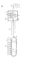
- FIG. 1 is a schematic diagram showing an example of a film production apparatus used in the solution casting method.
- the film manufacturing apparatus 10 includes an endless metal support 12, a die 14 for casting a dope on the metal support 12, and a dope film on the endless metal support 12.
- the drying device 24 transports the stretched film by a plurality of transport rollers 22 and dries, and the take-up roller 26 winds up the dried film.
- FIG. 1 an example in which the blower 16 is arranged so as to apply wind to a part of the transport direction of the dope film on the metal support 12 is shown, but the present invention is not limited to this. You may arrange
- the method of producing a film containing cellulose acetate by a solution casting method is as follows: 1) a step of preparing a dope by dissolving a cellulose ester and other components as required in a solvent, and 2) an endless dope.
- Dope preparation step In a dissolution vessel, a dope is prepared by dissolving cellulose acetate and other components as required in a solvent.
- the solvent contained in the dope may be one kind or a combination of two or more kinds.
- a good solvent refers to a solvent that dissolves cellulose acetate alone
- a poor solvent refers to a solvent that swells cellulose acetate or does not dissolve alone. Therefore, the good solvent and the poor solvent differ depending on the total substitution degree (acetyl group substitution degree) of the acyl group of cellulose acetate.
- the good solvent is more than the poor solvent in order to increase the solubility of cellulose acetate.
- the mixing ratio of the good solvent and the poor solvent is preferably 70 to 98% by mass for the good solvent and 2 to 30% by mass for the poor solvent.
- Examples of good solvents include organic halogen compounds such as dichloromethane, dioxolanes, acetone, methyl acetate, and methyl acetoacetate, and preferably dichloromethane.
- Examples of the poor solvent include methanol, ethanol, n-butanol, cyclohexane, cyclohexanone and the like, and preferably methanol.
- the concentration of cellulose acetate in the dope is preferably higher in order to reduce the drying load. However, if the concentration of cellulose acetate is too high, filtration is difficult. Therefore, the concentration of cellulose acetate in the dope is preferably 10 to 35% by mass, more preferably 15 to 25% by mass.
- Examples of the method of dissolving cellulose acetate in a solvent include a method of dissolving under heating and pressure, a method of adding a poor solvent to cellulose acetate to swell, a method of further adding a good solvent, and a cooling dissolution method. sell.
- dissolve under a heating and pressurization is preferable.
- stirring and dissolving while heating to a temperature that is equal to or higher than the boiling point of the solvent under normal pressure and does not boil under pressure the generation of massive undissolved material called gel or mako can be suppressed.
- the heating temperature is preferably higher from the viewpoint of increasing the solubility of cellulose acetate, but if it is too high, it is necessary to increase the pressure and the productivity is lowered. For this reason, the heating temperature is preferably 45 to 120 ° C., more preferably 60 to 110 ° C., and further preferably 70 to 105 ° C.
- the obtained dope may contain insoluble matters such as impurities contained in cellulose acetate as a raw material. Such an insoluble matter can become a bright spot foreign material in the obtained film. In order to remove such insoluble matter and the like, it is preferable to further filter the obtained dope.
- the die 14 is preferably a pressure die that can adjust the slit shape of the base portion and can easily adjust the film thickness.
- Examples of the pressure die include a coat hanger die and a T-die.
- the metal support 12 can be a metal belt such as a stainless steel belt or a metal drum.
- the conveyance distance of the metal support 12 can be about 5 m or more and 100 m or less.
- the surface of the dope film cast on the metal support 12 that is not in contact with the metal support 12 is the “surface A (uneven surface) of the film containing cellulose ester”;
- the surface can be a “surface B (smooth surface) of a film containing a cellulose ester”.
- the surface roughness of the surface B (smooth surface) of the film containing cellulose ester can be adjusted by the surface roughness of the metal support 12.
- the surface roughness of the metal support 12 is preferably 1.0 to 3.0 nm.
- the surface of the metal support is preferably mirror-finished.
- the surface temperature of the metal support 12 is preferably high in order to increase the drying rate of the dope film, but if it is too high, the dope film may foam. Therefore, the surface temperature of the metal support 12 is preferably set to ⁇ 50 ° C. or higher and lower than the boiling point of the solvent.
- the temperature of the dope film is preferably 0 to 55 ° C., more preferably 25 to 50 ° C.
- the cast dope film is heated on the metal support 12 and dried until the amount of residual solvent in the dope film becomes a certain level or less.
- the dope film is preferably dried by blowing air on the surface of the dope film (the surface not in contact with the metal support 12) by the blower 16.
- the surface roughness of the surface A (uneven surface) of the film containing cellulose ester can be adjusted by the wind speed applied to the dope film and the time of applying the wind. For example, in order to increase the surface roughness of the surface A (uneven surface) of the film, the wind speed applied to the dope film may be increased, or the time for applying the wind may be increased.
- the wind speed applied to the dope film is preferably 3 to 20 m / sec, and more preferably 5 to 15 m / sec.
- the wind speed is less than 3 m / sec, the surface of the dope film is not sufficiently roughened, so that it is difficult to make the surface roughness of the surface A (uneven surface) of the film obtained above a certain level (2.3 nm or more).
- the wind speed is more than 20 m / second, the surface of the dope film is too rough, and the surface roughness of the surface A (uneven surface) of the resulting film may be too large exceeding 5.0 nm.
- the temperature of the wind applied to the dope film may be about 25 to 100 ° C., and more preferably 40 to 100 ° C. in order to increase the drying speed.
- the time for applying the wind is preferably 5 seconds or more, more preferably 10 seconds or more, and further preferably 20 seconds or more.
- the upper limit of the time for applying the wind is preferably the time until casting (the web) is peeled from the metal support 12 after casting, preferably 150 seconds or less, and more preferably 60 seconds or less. preferable.
- the time for which the wind is applied can be adjusted by the length of the zone to which the wind is applied (by the blower 16) and the transport speed of the metal support 12.
- the size of the apparatus is adjusted by the transport speed of the metal support 12 in order to avoid an increase in size. It is preferable to do. In order to lengthen the time for which the wind is applied, the conveyance speed of the metal support 12 may be reduced.
- the length of the blowing zone by the blowing device 16 can be, for example, about 5 to 70% of the transport distance of the metal support 12.
- the conveying speed of the metal support 12 (film conveying speed) is preferably 1 to 30 m / min, and more preferably 3 to 25 m / min. If the conveying speed of the metal support 12 is less than 1 m / min, the productivity tends to decrease. On the other hand, when the conveying speed of the metal support 12 is more than 30 m / min, the time for applying air to the dope film on the metal support 12 is short, so the surface of the dope film is not sufficiently rough, The surface roughness of the surface A (uneven surface) tends to be small.
- the wind speed applied to the dope film and the surface roughness of the metal support 12 are respectively set to predetermined values. It is preferable to be in the range; and 2) it is more preferable that the conveying speed of the metal support 12 is set to a certain value or less.
- the web from which the solvent has been evaporated on the metal support 12 is peeled off by the peeling roller 18 or the like at the peeling position on the metal support 12.
- the temperature at the peeling position on the metal support 12 is preferably 10 to 40 ° C., more preferably 11 to 30 ° C.
- the residual solvent amount of the web when peeling at the peeling position on the metal support 12 is preferably 50 to 120% by mass, although it depends on the drying conditions and the length of the metal support.
- a web with a large amount of residual solvent tends to be too soft and rough, and wrinkles that extend in the vertical direction due to peeling tension tend to occur.
- the residual solvent amount of the web at the peeling position can be set so as to suppress such wrinkles extending in the vertical direction.
- the heat treatment for measuring the residual solvent amount means a heat treatment at 115 ° C. for 1 hour.
- the amount of residual solvent in the web can be adjusted by the drying temperature (wind temperature), the drying time (time during which the wind is applied), etc. in the solvent evaporation step described above.
- the peeling tension at the time of peeling the web from the metal support can usually be 300 N / m or less.
- Drying and stretching step The web obtained by peeling from the metal support 12 is dried as necessary, and then stretched by the stretching device 20.
- the web may be dried while being transported by a large number of rolls arranged vertically, or may be dried while being transported while fixing both ends of the web with clips.
- the method for drying the web may be a method of drying with hot air, infrared rays, a heating roll, microwaves, or the like, and a method of drying with hot air is preferable because it is simple.
- the drying temperature of the web can be about 40 to 250 ° C., preferably about 40 to 160 ° C.
- a retardation film having a desired retardation is obtained by stretching the web.
- the retardation of the retardation film can be controlled by adjusting the magnitude of the tension applied to the web.
- the web is stretched in the width direction (TD direction), the dope casting direction (MD direction), or in the oblique direction, and is preferably stretched at least in the width direction (TD direction).
- the web may be stretched uniaxially or biaxially.
- Biaxial stretching is preferably stretching in the dope casting direction (MD direction) and the width direction (TD direction).
- Biaxial stretching may be sequential biaxial stretching or simultaneous biaxial stretching.
- Sequential biaxial stretching includes a method in which stretching in different stretching directions is sequentially performed, a method in which stretching in the same direction is performed in multiple stages, and the like.
- Examples of sequential biaxial stretching include the following stretching steps. Stretch in the casting direction (MD direction)-Stretch in the width direction (TD direction)-Stretch in the casting direction (MD direction)-Stretch in the casting direction (MD direction) Stretch in the width direction (TD direction)-Stretch in the width direction Stretching (TD direction)-Stretching in the casting direction (MD direction)-Stretching in the casting direction (MD direction)-Stretching in the casting direction (MD direction)
- Simultaneous biaxial stretching includes a mode in which stretching is performed in one direction and the tension in the other direction is relaxed and contracted.
- the draw ratio depends on the film thickness of the protective film to be obtained and the required retardation value, but is finally 0.95 to 1.2 times in the casting direction, preferably 1.0 to 1.1.
- the width may be 1.05 to 2.0 times, preferably 1.1 to 1.5 times in the width direction.
- the stretching temperature of the web is preferably 120 ° C. to 200 ° C., more preferably 150 ° C. to 200 ° C., and even more preferably more than 150 ° C. and 190 ° C. or less.
- the residual solvent of the web at the start of stretching is preferably 20% by mass or less, more preferably 15% by mass or less.
- the stretching method of the web is not particularly limited, and a method (roll stretching method) in which a plurality of rolls are provided with a circumferential speed difference and stretched in the casting direction (MD direction) using the roll circumferential speed difference between them. Fix both ends with clips and pins, and widen the gap between the clips and pins in the casting direction (MD direction) and extend in the casting direction (MD direction), or widen in the width direction (TD direction) and the width direction (TD direction) or a method of extending in both the casting direction (MD direction) and the width direction (TD direction) by extending both in the casting direction (MD direction) and the width direction (TD direction) ( And a tenter stretching method). These stretching methods may be combined.
- the stretched film may be dried by a drying device 24 as necessary.
- the stretched film can be dried while being transported by a plurality of transport rollers 22. Thereafter, the obtained film is wound up by the winding roller 26.
- the cured resin layer is formed by applying a coating solution for a cured resin layer to the surface A (uneven surface) of the film containing cellulose ester as described above.
- the coating solution for the cured resin layer is applied to the surface A (uneven surface) of the film, and then dried and cured, thereby obtaining an anchor effect between the cured resin layer and the film containing the cellulose ester. it can. Therefore, even when the thickness of the film containing cellulose ester is thin, it is possible to make it difficult to generate burrs when the polarizing plate is cut.
- the cured resin layer contains a cured product of the active energy ray curable compound.
- the active energy ray-curable compound is a compound that is cured through a crosslinking reaction by irradiation with active energy rays such as ultraviolet rays and electron beams, and is preferably a compound having an ethylenically unsaturated double bond.
- Examples of the active energy ray curable compound include an ultraviolet curable compound and an electron beam curable compound, and the ultraviolet curable compound is preferable because the hardness of the cured product is high.
- the ultraviolet curable compound is preferably a polyfunctional acrylate.
- the polyfunctional acrylate is a compound having two or more acryloyloxy groups or methacryloyloxy groups in one molecule.
- Examples of the polyfunctional acrylate include pentaerythritol polyfunctional acrylate, dipentaerythritol polyfunctional acrylate, pentaerythritol polyfunctional methacrylate, dipentaerythritol polyfunctional methacrylate, and the like.
- the polyfunctional acrylate can be a monomer or an oligomer.
- the polyfunctional acrylate may be one kind or a mixture of two or more kinds.
- the cured resin layer may further contain a binder such as a hydrophilic resin, a thermoplastic resin, a thermosetting resin, and fine particles as necessary.
- a binder such as a hydrophilic resin, a thermoplastic resin, a thermosetting resin, and fine particles as necessary.
- Fine particles can be added for the purpose of imparting slipperiness and antiglare properties to the cured resin layer or adjusting the refractive index.
- the fine particles are inorganic compound or organic compound particles, preferably inorganic compound particles, and more preferably silica particles.
- silica particles include colloidal silica, and specific examples include MEK-ST-L, IPA-ST-L, and IPA-ST-ZL manufactured by Nissan Chemical Industries, Ltd.
- the average particle diameter of the fine particles is preferably 0.01 to 5 ⁇ m, more preferably 0.1 to 5.0 ⁇ m, and further preferably 0.1 to 4.0 ⁇ m.
- the content of fine particles in the cured resin layer is preferably 0.1 to 30 parts by mass with respect to 100 parts by mass of the curable resin.
- the cured resin layer can be a hard coat layer, an antiglare layer, an antireflection layer, or a combination thereof.
- the antireflection layer may be composed of only the low refractive index layer or may be composed of a plurality of refractive index layers having different refractive indexes.
- the cured resin layer is preferably a hard coat layer.
- the hard coat layer in the present invention is a transparent cured resin layer having no antiglare function or antireflection function.
- the hardness of the hard coat layer is preferably a pencil hardness of 3H or more, more preferably 4H or more.
- the pencil hardness is defined by JIS K-5400 using a test pencil specified by JIS S6006 after the film having a hard coat layer is conditioned at 23 ° C. and 55% RH for 2 hours or more. It can be measured according to the evaluation method.
- the thickness of the cured resin layer is preferably 3 to 30 ⁇ m, and more preferably 5 to 15 ⁇ m.
- Polarizer A polarizer is an element that allows only light of a plane of polarization in a certain direction to pass through.
- the polarizer is a polyvinyl alcohol polarizing film, preferably a polyvinyl alcohol uniaxially stretched film dyed with iodine or a dichroic dye.
- the dyed polyvinyl alcohol-based uniaxially stretched film may be a film obtained by uniaxially stretching a polyvinyl alcohol-based film and then dyed with iodine or a dichroic dye; or a polyvinyl alcohol-based film with iodine or a dichroic dye. After dyeing, it may be uniaxially stretched. Uniaxial stretching can be performed so that the final stretching ratio is about 5 times.
- the polyvinyl alcohol film may be a film formed from a polyvinyl alcohol aqueous solution.
- the polyvinyl alcohol film is preferably an ethylene-modified polyvinyl alcohol film because it is excellent in polarizing performance and durability performance and has few color spots.
- Examples of the ethylene-modified polyvinyl alcohol film include an ethylene unit content of 1 to 4 mol%, a degree of polymerization of 2000 to 4000, and a degree of saponification of 99 described in JP-A Nos. 2003-248123 and 2003-342322. 0.0-99.99 mol% film is included.
- dichroic dyes examples include azo dyes, stilbene dyes, pyrazolone dyes, triphenylmethane dyes, quinoline dyes, oxazine dyes, thiazine dyes and anthraquinone dyes.
- boron compound include boric acid.
- the thickness of the polarizer is not particularly limited, but is about 2 to 30 ⁇ m. In order to reduce the thickness of the polarizing plate, it is preferably 3 to 25 ⁇ m, and more preferably 10 ⁇ m or less.
- a polarizing plate may further contain another protective film in the surface on the opposite side to the surface by which the film containing the above-mentioned cellulose ester of a polarizer is arrange
- the other protective film may be a transparent resin film, and examples thereof include a cellulose ester film.
- the cellulose ester film include commercially available cellulose ester films (for example, Konica Minoltack KC8UX, KC5UX, KC8UCR3, KC8UCR4, KC8UCR5, KC8UY, KC6UY, KC4UY, KC4UE, KC8UE, KC8UY-HA-X8-U8-U8-HA-X8 -C, KC8UXW-RHA-NC, KC4UXW-RHA-NC, and the like manufactured by Konica Minolta Opto Co., Ltd.).
- the thickness of the other protective film is not particularly limited, but is about 10 to 200 ⁇ m, preferably 10 to 100 ⁇ m, and more preferably 10 to 70 ⁇ m.
- the polarizing plate of the present invention includes 1) a step of forming a cured resin layer on one side A (uneven surface) of a film containing cellulose ester, and 2) the other side of the film containing cellulose ester. And a step of attaching a polarizer to the surface B (smooth surface) via an adhesive.
- Step of forming a cured resin layer After applying the coating solution for the cured resin layer on one surface A (uneven surface) of the above-mentioned cellulose ester-containing film; irradiating the obtained coating layer with active energy rays Then, it is cured to form a cured resin layer.
- the coating resin for the cured resin layer contains a cured product of the above-described active energy ray-curable compound, and further contains a photopolymerization initiator, fine particles, a solvent and the like as necessary.
- Examples of the photopolymerization initiator include acetophenone, benzophenone, hydroxybenzophenone, ⁇ -hydroxyketone, Michler ketone, ⁇ -amyloxime ester, thioxanthone and derivatives thereof.
- Examples of commercially available products include dolcagua 184 (manufactured by Ciba Japan).
- the solvent examples include hydrocarbons, alcohols, ketones, esters, glycol ethers, etc., preferably glycol ethers.
- glycol ethers include propylene glycol mono (alkyl group having 1 to 4 carbon atoms) alkyl ether or propylene glycol mono (alkyl group having 1 to 4 carbon atoms) alkyl ether ester.
- the solvent may be one type or a mixture of two or more types. Among them, propylene glycol mono (alkyl group having 1 to 4 carbon atoms) alkyl ether or propylene glycol mono (alkyl group having 1 to 4 carbon atoms) alkyl ether ester is contained in an amount of 5% by mass or more, preferably 5 to 80% by mass. It is preferable.
- the content of the active energy ray-curable compound in the solid content of the coating resin for the cured resin layer may be 15% by mass or more and less than 70% by mass.
- the irradiation light source may be a light source that generates ultraviolet rays, and specifically, may be a low pressure mercury lamp, a medium pressure mercury lamp, a high pressure mercury lamp, an ultrahigh pressure mercury lamp, a carbon arc lamp, a metal halide lamp, a xenon lamp, or the like.
- the irradiation conditions vary depending on individual lamps, but the amount of light irradiated may if 20 ⁇ 10000mJ / cm 2 degrees, preferably 50 ⁇ 2000mJ / cm 2.
- the irradiation time is about 0.5 seconds to 5 minutes, and preferably 3 seconds to 2 minutes in order to improve the curing efficiency of the ultraviolet curable resin.
- Step of bonding the polarizer The other surface B (smooth surface) of the film containing the cellulose ester and the polarizer are bonded together with an adhesive.
- the adhesive used for bonding includes, for example, a polyvinyl alcohol-based adhesive.
- the polyvinyl alcohol-based adhesive includes a polyvinyl alcohol-based resin, and may further include a cross-linking agent as necessary.
- polyvinyl alcohol resins include saponified products of polyvinyl acetate or derivatives thereof; saponified products of copolymers of vinyl acetate and copolymer components; acetalized, urethanized, etherified, grafted or phosphorylated with polyvinyl alcohol. Examples include acid esterified modified polyvinyl alcohol.
- copolymer components include unsaturated carboxylic acids such as (anhydrous) maleic acid, fumaric acid, crotonic acid, itaconic acid, (meth) acrylic acid, and esters thereof; ⁇ -olefins such as ethylene and propylene; ) Allyl sulfonic acid (soda), sulfonic acid soda (monoalkylmalate), disulfonic acid soda alkylmalate, N-methylolacrylamide, acrylamide alkylsulfonic acid alkali salt, N-vinylpyrrolidone, N-vinylpyrrolidone derivatives, etc. It is.
- unsaturated carboxylic acids such as (anhydrous) maleic acid, fumaric acid, crotonic acid, itaconic acid, (meth) acrylic acid, and esters thereof; ⁇ -olefins such as ethylene and propylene; ) Allyl sulfonic acid (soda), sul
- the average degree of polymerization of the polyvinyl alcohol-based resin is preferably about 100 to 5000, and more preferably 1000 to 4000 from the viewpoint of adhesiveness.
- the average degree of saponification is preferably about 85 to 100 mol%, more preferably 90 to 100 mol% from the viewpoint of adhesiveness.
- the resin concentration of the polyvinyl alcohol-based adhesive is preferably 0.1 to 15% by weight, more preferably 0.5 to 10% by weight from the viewpoint of improving the coating property and storage stability.
- the application of the polyvinyl alcohol-based adhesive can be performed by, for example, a roll method, a spray method, a dipping method, or the like.
- the thickness of the adhesive layer obtained from the polyvinyl alcohol-based adhesive is about 10 to 300 nm, preferably 10 to 200 nm, more preferably 20 to 150 nm. If the thickness of the adhesive layer is within the above range, sufficient adhesiveness can be easily obtained.
- the other surface B (smooth surface) of the film containing the cellulose ester is preferably saponified by dipping or coating in a saponification solution (for example, an alkaline aqueous solution) in order to enhance the adhesion to the polarizer. .
- a saponification solution for example, an alkaline aqueous solution
- a cured resin layer is formed by applying a coating solution for a cured resin layer on one surface A (uneven surface) of a film containing cellulose ester. Since the coating liquid for cured resin layers follows the concavo-convex shape of the surface A of the film, the contact area between the cured resin layer and the film can be increased and the adhesion can be improved.
- a polarizer having a smooth surface is bonded to the other surface B (smooth surface) of the film containing cellulose ester. Thereby, a polarizer and a film can be made to adhere
- the polarizing plate is usually cut into a predetermined size and incorporated in the liquid crystal display device. Since the polarizing plate of the present invention has high adhesion between the film / cured resin layer and between the film / polarizer, the film is produced when the polarizing plate is cut into a predetermined size, which occurs when the film thickness is reduced. / Peeling between cured resin layers and between films / polarizers hardly occurs. Thereby, generation
- liquid crystal display device of the present invention has a liquid crystal cell and a pair of polarizing plates sandwiching the liquid crystal cell, and at least one of the pair of polarizing plates is the polarizing plate of the present invention.
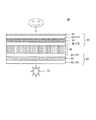
- FIG. 2 is a schematic diagram showing a basic configuration of an embodiment of a liquid crystal display device according to the present invention.
- the liquid crystal display device 30 includes a liquid crystal cell 40, a first polarizing plate 50 and a second polarizing plate 60 that sandwich the liquid crystal cell 40, and a backlight 70.
- the first polarizing plate 50 is preferably the polarizing plate of the present invention.
- the display method of the liquid crystal cell 40 is not particularly limited, and is a TN (Twisted Nematic) method, a STN (Super Twisted Nematic) method, an IPS (In-Plane Switching) method, an OCB (Optically CompensatedreBirrefrenceAbirefringenceVirentenceVirentenceVirentenceVirentenceVirentenceVirentenceVirentenceVirentenceVirentenceVirentyVirentenceVirentlenceAbireflenceAbirefringenceAbirefrence
- MVA Multi-domain Vertical Alignment and PVA; including Patterned Vertical Alignment
- HAN Hybrid Aligned Nematic
- a VA liquid crystal cell usually has two transparent substrates and a liquid crystal layer disposed between them and containing liquid crystal molecules.
- the pixel electrode is arranged on one of the two transparent substrates.
- the counter electrode may be disposed on one transparent substrate on which the pixel electrode is disposed, or may be disposed on the other transparent substrate.
- the liquid crystal layer includes liquid crystal molecules having negative or positive dielectric anisotropy.
- the liquid crystal molecules are preferably nematic liquid crystal molecules.
- the liquid crystal cell When no voltage is applied, the liquid crystal cell is aligned perpendicular to the surface of the transparent substrate.
- a voltage is applied, an electric field in a direction parallel to the surface of the transparent substrate is generated, and the liquid crystal molecules can be aligned so that the major axis thereof is parallel to the surface of the transparent substrate. In this way, the liquid crystal layer is driven, and the image display is performed by changing the transmittance and reflectance of each sub-pixel.
- the 1st polarizing plate 50 is arrange
- the second polarizing plate 60 is disposed on the backlight 70 side of the liquid crystal cell 40, and the second polarizer 62 and the protective film 64 disposed on the surface of the second polarizer 62 on the liquid crystal cell 40 side. (F3) and a protective film 66 (F4) disposed on the surface of the second polarizer 62 opposite to the liquid crystal cell 40.
- One of the protective films 56 (F2) and 64 (F3) may be omitted as necessary.
- the obtained fine particle dispersion 1 was slowly added to a dissolution tank charged with dichloromethane with sufficient stirring.
- the obtained solution was dispersed with an attritor so that the particle size of the secondary particles of the fine particles became a predetermined size, and then filtered with Finemet NF manufactured by Nippon Seisen Co., Ltd. 1 was obtained.
- Composition of fine particle additive liquid 1 Dichloromethane: 99 parts by mass Fine particle dispersion 1: 5 parts by mass
- composition of dope solution 1 Dichloromethane: 340 parts by mass Ethanol: 64 parts by mass Cellulose acetate A (acetyl group substitution degree 2.88, number average molecular weight 130000): 100 parts by mass Polyester compound 2-18: 5 parts by mass Polyester compound (6): 3 parts by mass Fine particles Additive liquid 1: 0.5 parts by mass
- the obtained dope solution 1 was adjusted to 33 ° C. and uniformly cast onto a stainless steel belt support with a width of 1500 mm using a belt casting apparatus.
- the surface roughness of the stainless steel belt support was 2.0 nm
- the conveyance speed of the stainless steel belt support was 20 m / min
- the surface temperature was 30 ° C.
- air was blown over the dope film on the stainless steel belt support for 2 seconds after 2 seconds to dry the residual solvent amount to 75% by mass.
- the wind speed applied to the dope film was 5 m / sec, and the temperature was 25 ° C. Thereafter, the dope film was peeled off from the stainless steel belt support with a peeling tension of 130 N / m to obtain a web.
- the obtained web was stretched by 10% in the web width direction (TD direction) at 160 ° C. with a tenter stretching machine.
- the residual solvent amount of the web when stretching was started was 15% by mass.
- the resulting film was dried at 130 ° C. while being conveyed by a number of rolls to obtain a film 101 having a thickness of 25 ⁇ m.
- the surface roughness, retardation, and internal haze of the obtained film were measured by the following methods. For the films of Production Examples 28 to 42, the retardation was not measured.
- the obtained film was cut out to obtain a sample having a size of 5 mm ⁇ 5 mm.
- the obtained sample is set on a sample stage of NT3300 manufactured by WYKO, and is defined by JIS B 0601: 2001 on the surface of the sample under the conditions of an objective lens 50 ⁇ , an image zoom 1.0 ⁇ , and a measurement area 120 ⁇ m ⁇ 90 ⁇ m.
- the arithmetic average roughness Ra was measured.
- the arithmetic average roughness Ra of the other surface of the sample was also measured.
- the retardation value R ( ⁇ ) was measured at 6 points every 10 °, with ⁇ ranging from 0 ° to 50 °. 4) From the measured Ro and R ( ⁇ ) and the above-mentioned average refractive index and film thickness, nx, ny and nz were calculated by KOBRA21ADH, and Rth at a measurement wavelength of 590 nm was calculated.
- the internal haze of the film was measured by a method according to JIS K-7136; specifically, the following method.
- a haze meter (model: NDH 2000, manufactured by Nippon Denshoku Co., Ltd.) was prepared.
- the light source was a halogen bulb of 5V9W, and the light receiving part was a silicon photocell (with a relative visibility filter).
- Internal haze is less than 0.2 ⁇ : Internal haze is 0.2 or more and less than 2.5 ⁇ : Internal haze is 2.5 or more
- compositions and evaluation results of the films obtained in Production Examples 1 to 18 are shown in Table 1; the compositions and evaluation results of the films obtained in Production Examples 19 to 27 are shown in Table 2, and obtained in Production Examples 28 to 42.
- Table 3 shows the composition and evaluation results of the film.
- Addition 1 / Addition 2 indicate the contents (parts by mass) of Additive 1 and Additive 2.
- Ra of the surface A (uneven surface) of the film can be increased by increasing the wind speed applied to the dope film. Further, as shown in Production Examples 1 and 14 to 18 in Table 1, it can be seen that Ra of the surface A (uneven surface) of the film can be increased by reducing the conveying speed of the support. Furthermore, as shown in Production Examples 19 to 20 in Table 2, it can be seen that Ra on the surface B (smooth surface) of the film can be reduced by reducing Ra on the surface of the support.
- the film of Production Example 1 in Table 1 having a surface A surface roughness of 5 nm or less is produced in Production Examples 6 to 7 in Table 1 and Surface Production Example 24 in Table 2 where the surface roughness Ra of surface A is more than 5 nm. It can be seen that the internal haze is lower than that of the film.
- Pentaerythritol triacrylate 20 parts by mass
- Pentaerythritol tetraacrylate 50 parts by mass Dipentaerythritol hexaacrylate: 30 parts by mass Dipentaerythritol pentaacrylate: 30 parts by mass
- Irgacure 184 5.0 parts by mass
- Poly Ether-modified silicone KF354L, manufactured by Shin-Etsu Chemical Co., Ltd.
- Propylene glycol monomethyl ether 10 parts by mass Methyl acetate: 45 parts by mass Methyl ethyl ketone: 65 parts by mass Cyclohexanone: 10 parts by mass
- the obtained coating liquid for hard coat layer was applied to the surface A (uneven surface) of the film 101 using a micro gravure coater, and then dried at 80 ° C. to obtain a coating layer.
- the obtained coating layer by using an ultraviolet lamp, irradiance 80 mW / cm 2, irradiating ultraviolet radiation under conditions of irradiation dose 80 mJ / cm 2, to cure the coating layers. Thereby, a film 101 having a hard coat layer having a dry thickness of 8 ⁇ m was obtained.
- the hard coat layer of the film 101 having the hard coat layer was irradiated with ultraviolet rays for 100 hours under the condition of an illuminance of 80 mW / cm 2 . Thereafter, the adhesion between the film and the hard coat layer was measured by a cross cut test according to JIS K5600-5-6 according to the following procedure. 1) Using a cutter knife, 1 ⁇ 1 mm square cuts were made on the surface of the hard coat layer to form 100 grids. 2) Next, after the cellotape (registered trademark) was strongly pressed on the surface of the hard coat layer, the end of the tape was peeled off at an angle of 45 °.
- the cellotape registered trademark
- polarizing plate 201 was produced according to the following steps 1 to 5.
- Step 1 The prepared film 101 having a hard coat layer was immersed in a 2 mol / L potassium hydroxide solution at 60 ° C. for 30 seconds, then washed with water and dried to saponify the surface.
- the surface of Konica Minolta Tac KC4UY (cellulose ester film manufactured by Konica Minolta Opto) was saponified.
- Step 2 The polarizer prepared above was immersed in a polyvinyl alcohol adhesive having a solid content of 2% by mass for 1 to 2 seconds.
- Step 3 After lightly wiping off excess adhesive adhering to the surface of the polarizer, the saponified film 101 is placed on one side of the polarizer, and the saponified Konica Minoltack KC4UY is placed on the other side To obtain a laminate.
- Step 4 The laminate obtained in Step 3 was bonded at a pressure of 20 to 30 N / cm 2 and a conveyance speed of about 2 m / min.
- Step 5 The laminated laminate was dried in a dryer at 80 ° C. for 2 minutes to obtain a polarizing plate 201.
- the obtained polarizing plate 201 was cut out to a size of 100 mm square. When the obtained polarizing plate was twisted by hand, the adhesive state of the film / polarizer was visually observed. The adhesiveness of the film / polarizer adhesion state was determined based on the following criteria. ⁇ : The polarizer / film is integrated on the entire surface of the polarizing plate, and peeling does not occur. ⁇ ⁇ : At the end of the polarizing plate, some peeling occurs between the film / polarizer. ⁇ : At the end of the polarizing plate. , Peeling occurs between the film / polarizer ⁇ : peeling occurs between the film / polarizer on the entire surface of the polarizing plate
- the obtained polarizing plate 201 was cut every 50 mm with a guillotine-shaped cutter to obtain 10 cut pieces. The cut surface of the obtained cut piece was visually observed, and the cutability of the polarizing plate was evaluated based on the following criteria. If ⁇ , ⁇ , and ⁇ ⁇ , the polarizing plate was judged to have a practically satisfactory level of cutting ability. ⁇ : No burrs are generated in all 10 cut pieces. ⁇ : Burr is generated in one of 10 cut pieces. ⁇ : Burr is generated in 2 out of 10 cut pieces. ⁇ : 10 pieces. Burr occurs on 3 of the cut pieces. ⁇ : Burr occurs on 4 or more of the 10 cut pieces.
- Examples 2 to 33 Comparative Examples 1 to 11 and Reference Example
- a film having a hard coat layer was prepared in the same manner as in Example 1 except that the film thickness of the film 101 and the polarizer was changed as shown in Tables 4 to 6, and the adhesion between the hard coat layer and the film was improved. evaluated.
- polarizing plates 202 to 229 and 231 to 246 were produced using the films having these hard coat layers in the same manner as in Example 1, and the adhesiveness to the polarizer and the cutting property of the polarizing plate were evaluated.
- Example 12 A film having a hard coat layer was prepared in the same manner as in Example 1 except that a hard coat layer was formed on the surface B (smooth surface) of the film 101, and the adhesion between the hard coat layer and the film was evaluated. Furthermore, a polarizing plate 230 was produced in the same manner as in Example 1 except that a polarizer was bonded onto the surface A (uneven surface) of the film 101, and the adhesiveness to the polarizer and the cutting property of the polarizing plate were evaluated. .
- Evaluation results of Examples 1 to 12 and Comparative Examples 1 to 6 are shown in Table 4; Evaluation results of Examples 13 to 18, Comparative Examples 7 to 12 and Reference Example are shown in Table 5; Evaluations of Examples 19 to 33 The results are shown in Table 6.
- the polarizing plates produced in Examples 1 to 33 have high adhesion between the film / polarizer and the film / hard coat layer, and when the polarizing plate is cut. It can be seen that burrs are less likely to occur.
- the polarizing plates produced in Comparative Examples 1 to 12 had low adhesion between the film / polarizer and the film / hard coat layer, and the polarizing plate was cut. It can be seen that burrs are likely to occur.
- the polarizing plate of Comparative Example 12 in which a polarizer is laminated on the surface A (uneven surface) of the film and a hard coat layer is laminated on the surface B (smooth surface), has a hard coat layer laminated on the surface A (uneven surface);
- the adhesiveness between the film / polarizer and the film / hard coat layer is lower than that of the polarizing plate of Example 1 in which a polarizer is laminated on the surface B (smooth surface), and burrs are likely to occur when the polarizing plate is cut. I understand.
- the polarizing plate obtained in the reference example of Table 5 has a film thickness of 50 ⁇ m, which indicates that no burrs are generated when the polarizing plate is cut.
- the polarizing plate of Example 1 of Table 4 using a film containing a polyester compound has fewer burrs at the time of cutting than the polarizing plate of Example 24 of Table 6 using a film containing a phosphate ester compound. It is shown. This is presumably because the film containing the polyester compound has higher flexibility than the film containing the phosphate compound.
- the polarizing plate of the present invention has high interlayer adhesion, and can suppress burrs when the polarizing plate is cut.
Landscapes
- Physics & Mathematics (AREA)
- General Physics & Mathematics (AREA)
- Optics & Photonics (AREA)
- Polarising Elements (AREA)
- Surface Treatment Of Optical Elements (AREA)
- Laminated Bodies (AREA)
Abstract
本発明の目的は、層間の接着性が高く、偏光板を切断するときのバリを抑制しうる偏光板を提供することである。本発明の偏光板は、厚み15~45μmであり、セルロースエステルを含むフィルムと、前記フィルムの一方の面A上に配置された硬化樹脂層と、前記フィルムの他方の面B上に配置された偏光子と、を含み、前記フィルムの前記一方の面Aの表面粗さRa(A)が2.3~5.0nmであり、前記フィルムの前記他方の面Bの表面粗さRa(B)が1.0~3.0nmであり、かつ前記表面粗さRa(A)と前記表面粗さRa(B)との差(Ra(A)-Ra(B))が0.3~2.5nmである。
Description
本発明は、偏光板に関する。
液晶表示装置は、テレビやパソコンなどの液晶ディスプレイとして広く用いられている。液晶表示装置は、液晶セルと、それを挟持する一対の偏光板とを有し;偏光板は、偏光子と、それを挟持する保護フィルムとを有する。保護フィルムとしては、セルロースエステルフィルムなどが用いられている。
セルロースエステルフィルムは、例えば溶液製膜法(例えば特許文献1~5)や、溶融製膜法(例えば特許文献6)により製造されることが知られている。特許文献1~5には、溶液製膜法では、セルロースエステルを含有するドープを、金属ベルト上に流延した後、ドープ膜に風を当てて乾燥させることが開示されている。
ところで、液晶表示装置において最も視認側に配置される保護フィルムF1の表面には、耐傷性を高めるためなどから、ハードコート層などの硬化樹脂層が設けられることがある。即ち、保護フィルムF1の一方の面には硬化樹脂層が積層され、他方の面には偏光子が積層されることがある。
しかしながら、硬化樹脂層と保護フィルムとの接着性と、保護フィルムと偏光子との接着性を両立することは難しかった。
また、液晶表示装置の薄型化が要望されている。本発明者らは、保護フィルムや偏光子の薄膜化を検討した。その結果、保護フィルムを薄膜化した場合には、偏光板の切断時に、前述の層間の接着不良に起因する層間で剥離が生じやすく、それにより切断面でのバリが生じやすいという課題が見出された。この課題は、保護フィルムが従来のように厚膜である場合には生じにくく、薄膜である場合に生じる新たな課題であった。
本発明は、上記事情に鑑みてなされたものであり、薄膜の保護フィルムを使用しても、偏光板を切断するときのバリを抑制しうる偏光板を提供することを目的とする。
[1] 厚み15~45μmであり、セルロースエステルを含むフィルムと、前記フィルムの一方の面A上に配置された硬化樹脂層と、前記フィルムの他方の面B上に配置された偏光子と、を含み、前記フィルムの前記一方の面Aの表面粗さRa(A)が2.3~5.0nmであり、前記フィルムの前記他方の面Bの表面粗さRa(B)が1.0~3.5nmであり、かつ前記表面粗さRa(A)と前記表面粗さRa(B)との差(Ra(A)-Ra(B))が0.3~2.5nmである、偏光板。
[2] 前記フィルムに含まれる前記セルロースエステルは、アセチル基置換度が2.5~3.0であり、かつアセチル基以外のアシル基の置換度が0.5以下であるセルロースアセテートである、[1]に記載の偏光板。
[3] 前記フィルムは、ポリエステル化合物をさらに含む、[1]または[2]に記載の偏光板。
[4] 前記硬化樹脂層は、ハードコート層である、[1]~[3]のいずれかに記載の偏光板。
[5] 前記偏光子の厚みが、3~25μmである、[1]~[4]のいずれかに記載の偏光板。
[6] 前記ハードコート層は、多官能アクリレートの硬化物を含む、[4]に記載の偏光板。
[7] 前記偏光子は、ポリビニルアルコール系偏光フィルムである、[1]~[6]のいずれかに記載の偏光板。
本発明の偏光板は、薄膜の保護フィルムを含むにも係わらず、偏光板を切断するときの切断面でのバリが抑制されうる。
1.偏光板
本発明の偏光板は、セルロースエステルを含むフィルムと、その一方の面A(凹凸面)上に配置された硬化樹脂層と、他方の面B(平滑面)上に配置された偏光子と、を含む。
本発明の偏光板は、セルロースエステルを含むフィルムと、その一方の面A(凹凸面)上に配置された硬化樹脂層と、他方の面B(平滑面)上に配置された偏光子と、を含む。
セルロースエステルを含むフィルム
セルロースエステルを含むフィルムは、セルロースエステルと、必要に応じて添加剤とを含む。
セルロースエステルを含むフィルムは、セルロースエステルと、必要に応じて添加剤とを含む。
セルロースエステル
セルロースエステルは、セルロースの水酸基を、脂肪族カルボン酸または芳香族カルボン酸でエステル化して得られる化合物である。
セルロースエステルは、セルロースの水酸基を、脂肪族カルボン酸または芳香族カルボン酸でエステル化して得られる化合物である。
セルロースエステルに含まれるアシル基は、脂肪族アシル基または芳香族アシル基であり、好ましくは脂肪族アシル基である。なかでも、脂肪族アシル基の炭素数は、2~6であることが好ましく、2~4であることがより好ましい。炭素数2~4の脂肪族アシル基の例には、アセチル基、プロピオニル基、ブタノイル基などが含まれ、より好ましくはアセチル基である。
セルロースエステルのアシル基の総置換度は、2.0~3.0であり、耐湿性を高めるためには、好ましくは2.5~3.0である。
セルロースエステルのアシル基の置換度は、ASTM-D817-96に準じて測定することができる。
セルロースエステルの例には、セルロースアセテート、セルロースプロピオネート、セルロースブチレート、セルロースアセテートプロピオネート、セルロースアセテートブチレートなどが含まれ、好ましくはセルロースアセテートである。
セルロースアセテートのアセチル基の置換度は、耐湿性を高めたり、位相差を発現させすぎないようにしたりするために、好ましくは2.5~3.0であり、より好ましくは2.8~2.95である。セルロースアセテートに含まれる、アセチル基以外のアシル基の置換度は0.5以下であることが好ましく、0であることがより好ましい。
セルロースアセテートの数平均分子量は、機械的強度が高いフィルムを得るためには、3.0×10⁴以上2.0×10⁵未満であることが好ましく、4.5×10⁴以上1.5×10⁵未満であることがより好ましい。セルロースアセテートの重量平均分子量は、1.2×10⁵以上2.5×10⁵未満であることが好ましく、1.5×10⁵以上2.0×10⁵未満であることがより好ましい。
セルロースアセテートの分子量分布(重量平均分子量Mw/数平均分子量Mn)は、1.0~4.5であることが好ましい。
セルロースエステルの数平均分子量Mnおよび重量平均分子量Mwは、ゲルパーミエーションクロマトグラフィー(GPC)により測定することができる。測定条件は以下の通りである。
溶媒:メチレンクロライド
カラム:Shodex K806、K805、K803G(昭和電工(株)製)を3本接続して使用する。
カラム温度:25℃
試料濃度:0.1質量%
検出器:RI Model 504(GLサイエンス社製)
ポンプ:L6000(日立製作所(株)製)
流量:1.0ml/min
校正曲線:標準ポリスチレンSTK standardポリスチレン(東ソー(株)製)Mw=1.0×10⁶~5.0×10²までの13サンプルによる校正曲線を使用する。13サンプルは、ほぼ等間隔に選択することが好ましい。
溶媒:メチレンクロライド
カラム:Shodex K806、K805、K803G(昭和電工(株)製)を3本接続して使用する。
カラム温度:25℃
試料濃度:0.1質量%
検出器:RI Model 504(GLサイエンス社製)
ポンプ:L6000(日立製作所(株)製)
流量:1.0ml/min
校正曲線:標準ポリスチレンSTK standardポリスチレン(東ソー(株)製)Mw=1.0×10⁶~5.0×10²までの13サンプルによる校正曲線を使用する。13サンプルは、ほぼ等間隔に選択することが好ましい。
セルロースエステルは、公知の方法で合成することができる。例えば、セルロースと、少なくとも酢酸またはその無水物を含む、炭素数3以上の有機酸またはその無水物とを、触媒(硫酸など)の存在下でエステル化反応させるステップを経て得ることができる(特開平10-45804号に記載の方法を参照)。
セルロースアセテートの原料であるセルロースの例には、綿花リンター、木材パルプ(針葉樹由来、広葉樹由来)およびケナフなどが含まれる。原料となるセルロースは、一種類だけであってもよいし、二種類以上の混合物であってもよい。
添加剤
セルロースエステルを含有するフィルムに含まれうる添加剤は、可塑剤、紫外線吸収剤、酸化防止剤、光安定剤、レターデーション調整剤、帯電防止剤、剥離剤などでありうる。
セルロースエステルを含有するフィルムに含まれうる添加剤は、可塑剤、紫外線吸収剤、酸化防止剤、光安定剤、レターデーション調整剤、帯電防止剤、剥離剤などでありうる。
可塑剤の例には、ポリエステル化合物、多価アルコールエステル化合物、多価カルボン酸エステル化合物(フタル酸エステル化合物を含む)、グリコレート化合物、およびエステル化合物(脂肪酸エステル化合物やリン酸エステル化合物などを含む)が含まれる。これらは、単独で用いても、二種類以上を組み合わせて用いてもよい。
ポリエステル化合物
ポリエステル化合物は、ジカルボン酸とジオールを反応させて得られる繰り返し単位を含む化合物である。
ポリエステル化合物は、ジカルボン酸とジオールを反応させて得られる繰り返し単位を含む化合物である。
ポリエステル化合物を構成するジカルボン酸は、芳香族ジカルボン酸、脂肪族ジカルボン酸または脂環式ジカルボン酸であり、好ましくは芳香族ジカルボン酸である。ジカルボン酸は、一種類であっても、二種類以上の混合物であってもよい。
ポリエステル化合物を構成するジオールは、芳香族ジオール、脂肪族ジオールまたは脂環式ジオールであり、好ましくは脂肪族ジオールであり、より好ましくは炭素数1~4のジオールである。ジオールは、一種類であっても、二種類以上の混合物であってもよい。
ポリエステル化合物の分子の両末端は、封止されていても、封止されていなくてもよいが、フィルムの耐湿性を高めるためには、封止されていることが好ましい。
ポリエステル化合物は、一般式(1)または(2)で表される化合物であることが好ましい。下記式において、nは1以上の整数である。
一般式(1)
B-(G-A)n-G-B
一般式(2)
C-(A-G)n-A-C
一般式(1)
B-(G-A)n-G-B
一般式(2)
C-(A-G)n-A-C
一般式(1)および(2)のAは、炭素数3~20(好ましくは4~12)のアルキレンジカルボン酸から誘導される2価の基、炭素数4~20(好ましくは4~12)のアルケニレンジカルボン酸から誘導される2価の基、または炭素数8~20(好ましくは8~12)のアリールジカルボン酸から誘導される2価の基を表す。
Aにおける炭素数3~20のアルキレンジカルボン酸から誘導される2価の基の例には、1,2-エタンジカルボン酸(コハク酸)、1,3-プロパンジカルボン酸(グルタル酸)、1,4-ブタンジカルボン酸(アジピン酸)、1,5-ペンタンジカルボン酸(ピメリン酸)、1,8-オクタンジカルボン酸(セバシン酸)などから誘導される2価の基が含まれる。Aにおける炭素数4~20のアルケニレンジカルボン酸から誘導される2価の基の例には、マレイン酸、フマル酸などから誘導される2価の基が含まれる。Aにおける炭素数8~20のアリールジカルボン酸から誘導される2価の基の例には、1,2-ベンゼンジカルボン酸(フタル酸)、1,3-ベンゼンジカルボン酸、1,4-ベンゼンジカルボン酸、1,5-ナフタレンジカルボン酸などのナフタレンジカルボン酸などから誘導される2価の基が含まれる。
Aは、一種類であっても、二種類以上が組み合わされてもよい。なかでも、Aは、炭素数4~12のアルキレンジカルボン酸と炭素数8~12のアリールジカルボン酸との組み合わせが好ましい。
一般式(1)および(2)のGは、炭素数2~20(好ましくは2~12)のアルキレングリコールから誘導される2価の基、炭素数6~20(好ましくは6~12)のアリールグリコールから誘導される2価の基、または炭素数4~20(好ましくは4~12)のオキシアルキレングリコールから誘導される2価の基を表す。
Gにおける炭素数2~20のアルキレングリコールから誘導される2価の基の例には、エチレングリコール、1,2-プロピレングリコール、1,3-プロピレングリコール、1,2-ブタンジオール、1,3-ブタンジオール、1,2-プロパンジオール、2-メチル-1,3-プロパンジオール、1,4-ブタンジオール、1,5-ペンタンジオール、2,2-ジメチル-1,3-プロパンジオール(ネオペンチルグリコール)、2,2-ジエチル-1,3-プロパンジオール(3,3-ジメチロールペンタン)、2-n-ブチル-2-エチル-1,3-プロパンジオール(3,3-ジメチロールヘプタン)、3-メチル-1,5-ペンタンジオール、1,6-ヘキサンジオール、2,2,4-トリメチル-1,3-ペンタンジオール、2-エチル-1,3-ヘキサンジオール、2-メチル-1,8-オクタンジオール、1,9-ノナンジオール、1,10-デカンジオール、および1,12-オクタデカンジオール等から誘導される2価の基が含まれる。
Gにおける炭素数6~20のアリールグリコールから誘導される2価の基の例には、1,2-ジヒドロキシベンゼン(カテコール)、1,3-ジヒドロキシベンゼン(レゾルシノール)、1,4-ジヒドロキシベンゼン(ヒドロキノン)などから誘導される2価の基が含まれる。Gにおける炭素数が4~12のオキシアルキレングリコールから誘導される2価の基の例には、ジエチレングルコール、トリエチレングリコール、テトラエチレングリコール、ジプロピレングリコール、トリプロピレングリコールなどから誘導される2価の基が含まれる。
Gは、一種類であっても、二種類以上が組み合わされてもよい。なかでも、Gは、炭素数2~12のアルキレングリコールであることが好ましい。
一般式(1)のBは、芳香環含有モノカルボン酸または脂肪族モノカルボン酸から誘導される1価の基である。
芳香環含有モノカルボン酸から誘導される1価の基における芳香環含有モノカルボン酸は、分子内に芳香環を含有するカルボン酸であり、芳香環がカルボキシル基と直接結合したものだけでなく、芳香環がアルキレン基などを介してカルボキシル基と結合したものも含む。芳香環含有モノカルボン酸から誘導される1価の基の例には、安息香酸、パラターシャリブチル安息香酸、オルソトルイル酸、メタトルイル酸、パラトルイル酸、ジメチル安息香酸、エチル安息香酸、ノルマルプロピル安息香酸、アミノ安息香酸、アセトキシ安息香酸、フェニル酢酸、3-フェニルプロピオン酸などから誘導される1価の基が含まれる。
脂肪族モノカルボン酸から誘導される1価の基の例には、酢酸、プロピオン酸、ブタン酸、カプリル酸、カプロン酸、デカン酸、ドデカン酸、ステアリン酸、オレイン酸などから誘導される1価の基が含まれる。なかでも、アルキル部分の炭素原子数が1~3であるアルキルモノカルボン酸から誘導される1価の基が好ましく、アセチル基(酢酸から誘導される1価の基)がより好ましい。
一般式(2)のCは、芳香環含有モノアルコールまたは脂肪族モノアルコールから誘導される1価の基である。
芳香環含有モノアルコールは、分子内に芳香環を含有するアルコールであり、芳香環がOH基と直接結合したものだけでなく、芳香環がアルキレン基などを介してOH基と結合したものも含む。芳香環含有モノアルコールから誘導される1価の基の例には、ベンジルアルコール、3-フェニルプロパノールなどから誘導される1価の基が含まれる。
脂肪族モノアルコールから誘導される1価の基の例には、メタノール、エタノール、プロパノール、イソプロパノール、ブタノール、イソブタノール、ペンタノール、イソペンタノール、ヘキサノール、イソヘキサノール、シクロヘキシルアルコール、オクタノール、イソオクタノール、2-エチルヘキシルアルコール、ノニルアルコール、イソノニルアルコール、tert-ノニルアルコール、デカノール、ドデカノール、ドデカヘキサノール、ドデカオクタノール、アリルアルコール、オレイルアルコールなどから誘導される1価の基が含まれる。なかでも、メタノール、エタノール、プロパノール、イソプロパノールなどの炭素数1~3のアルコールから誘導される1価の基が好ましい。
ポリエステル化合物の重量平均分子量は、300~1500であることが好ましく、400~1000であることがより好ましい。重量平均分子量が300未満であるポリエステル化合物は、フィルムから染み出しやすいことがある。
ポリエステル化合物の酸価は、それを含むセルロースエステルフィルムと、ハードコート層などの他の機能層との密着性を高めうる観点などから、0.5mgKOH/g以下であることが好ましく、0.3mgKOH/g以下であることがより好ましい。ポリエステル化合物の酸価とは、試料1g中に含まれる酸(試料中に存在するカルボキシル基)を中和するために必要な水酸化カリウムのミリグラム数として定義される。ポリエステル化合物の酸価は、JIS K0070に準拠して測定されうる。
ポリエステル化合物の具体例を、以下に示す。まず、「芳香族基」で両末端を封止したポリエステル化合物の具体例を示す。


次に、「脂肪族基」で両末端を封止したポリエステル化合物の具体例を、以下に示す。

P-1:アジピン酸/フタル酸/エタンジオール(1/1/2 モル比)からなる縮合物(重量平均分子量950)の両末端のアセチルエステル化体
P-2:コハク酸/フタル酸/エタンジオール/(1/1/2 モル比)からなる縮合物(重量平均分子量2500)の両末端のアセチルエステル化体
P-2:コハク酸/フタル酸/エタンジオール/(1/1/2 モル比)からなる縮合物(重量平均分子量2500)の両末端のアセチルエステル化体
ポリエステル化合物の含有量は、セルロースエステルに対して1~40質量%であることが好ましく、2~20質量%であることがより好ましく、3~10質量%であることがさらに好ましい。ポリエステル化合物の含有量が1質量%未満であると、偏光板切断時のバリを抑制できる程度の十分な柔軟性をフィルムに付与できないことがある。一方、ポリエステル化合物の含有量が40質量%超であると、ブリードアウトを生じやすい。
多価アルコールエステル系可塑剤は、2価以上の脂肪族多価アルコールと、モノカルボン酸とのエステル化合物(アルコールエステル)であり、好ましくは2~20価の脂肪族多価アルコールエステルである。多価アルコールエステル系可塑剤は、分子内に芳香環またはシクロアルキル環を有することが好ましい。
多価アルコールエステル系可塑剤における脂肪族多価アルコールの好ましい例には、トリメチロールプロパンおよびペンタエリスリトールなどが含まれる。
多価アルコールエステル系可塑剤におけるモノカルボン酸の例には、脂肪族モノカルボン酸、脂環族モノカルボン酸、芳香族モノカルボン酸などが含まれる。透湿性、ブリードアウトを抑制する観点などから、脂環式モノカルボン酸、芳香族モノカルボン酸が好ましい。脂肪族モノカルボン酸の好ましい例には、酢酸などの炭素原子数1~10の脂肪族モノカルボン酸が含まれる。脂環式モノカルボン酸の好ましい例には、シクロペンタンカルボン酸、シクロヘキサンカルボン酸、シクロオクタンカルボン酸などが含まれる。芳香族モノカルボン酸の好ましい例には、安息香酸が含まれる。
多価アルコールエステル系可塑剤の分子量は、特に制限はないが、300~1500であることが好ましく、350~750であることがより好ましい。多価アルコールエステル系可塑剤の分子量は、ブリードアウトを抑制する観点では、大きいほうが好ましく;透湿性やセルロースエステルとの相溶性の観点では、小さいほうが好ましい。
2価のアルコールエステル系可塑剤の例には、以下のものが含まれる。

3価以上のアルコールエステル系可塑剤の例には、以下のものが含まれる。


多価カルボン酸エステル系可塑剤は、2価以上、好ましくは2~20価の多価カルボン酸と、アルコール化合物とのエステル化合物である。多価カルボン酸は、2~20価の脂肪族多価カルボン酸であるか、3~20価の芳香族多価カルボン酸または3~20価の脂環式多価カルボン酸であることが好ましい。
多価カルボン酸エステル系可塑剤における多価カルボン酸の例には、トリメリット酸、ピロメリット酸などの3価以上の芳香族多価カルボン酸;コハク酸、アジピン酸などの脂肪族多価カルボン酸;酒石酸、リンゴ酸、クエン酸のようなオキシ多価カルボン酸などが含まれる。なかでも、ブリードアウトを抑制する観点から、オキシ多価カルボン酸が好ましい。
多価カルボン酸エステル系可塑剤におけるアルコールの例には、炭素原子数1~10の飽和または不飽和の脂肪族アルコール;シクロペンタノール、シクロヘキサノールなどの脂環式アルコール;ベンジルアルコール、シンナミルアルコールなどの芳香族アルコールなどが含まれる。
多価カルボン酸エステル系可塑剤の分子量は、特に制限はないが、300~1000であることが好ましく、350~750であることがより好ましい。多価カルボン酸エステル系可塑剤の分子量は、ブリードアウトを抑制する観点では、大きいほうが好ましく;透湿性やセルロースエステルとの相溶性の観点では、小さいほうが好ましい。
多価カルボン酸エステル系可塑剤の例には、トリエチルシトレート、トリブチルシトレート、アセチルトリエチルシトレート(ATEC)、アセチルトリブチルシトレート(ATBC)、ベンゾイルトリブチルシトレート、アセチルトリフェニルシトレート、アセチルトリベンジルシトレート、酒石酸ジブチル、酒石酸ジアセチルジブチル、トリメリット酸トリブチル、ピロメリット酸テトラブチル等が含まれる。
多価カルボン酸エステル系可塑剤は、フタル酸エステル系可塑剤であってもよい。フタル酸エステル系可塑剤の例には、ジエチルフタレート、ジメトキシエチルフタレート、ジメチルフタレート、ジオクチルフタレート、ジブチルフタレート、ジ-2-エチルヘキシルフタレート、ジオクチルフタレート、ジシクロヘキシルフタレート、ジシクロヘキシルテレフタレート等が含まれる。
グリコレート系可塑剤の例には、アルキルフタリルアルキルグリコレート類が含まれる。アルキルフタリルアルキルグリコレート類の例には、メチルフタリルメチルグリコレート、エチルフタリルエチルグリコレート、プロピルフタリルプロピルグリコレート、ブチルフタリルブチルグリコレート、オクチルフタリルオクチルグリコレート、メチルフタリルエチルグリコレート、エチルフタリルメチルグリコレート、エチルフタリルプロピルグリコレート、メチルフタリルブチルグリコレート、エチルフタリルブチルグリコレート、ブチルフタリルメチルグリコレート、ブチルフタリルエチルグリコレート、プロピルフタリルブチルグリコレート、ブチルフタリルプロピルグリコレート、メチルフタリルオクチルグリコレート、エチルフタリルオクチルグリコレート、オクチルフタリルメチルグリコレート、オクチルフタリルエチルグリコレート等が含まれる。
エステル系可塑剤には、脂肪酸エステル系可塑剤、クエン酸エステル系可塑剤やリン酸エステル系可塑剤などが含まれる。
脂肪酸エステル系可塑剤の例には、オレイン酸ブチル、リシノール酸メチルアセチル、およびセバシン酸ジブチル等が含まれる。クエン酸エステル系可塑剤の例には、クエン酸アセチルトリメチル、クエン酸アセチルトリエチル、およびクエン酸アセチルトリブチル等が含まれる。リン酸エステル系可塑剤の例には、トリフェニルホスフェート、トリクレジルホスフェート、クレジルジフェニルホスフェート、オクチルジフェニルホスフェート、ジフェニルビフェニルホスフェート、トリオクチルホスフェート、およびトリブチルホスフェート等が含まれる。
なかでも、フィルムの可塑性や柔軟性を効果的に高めうることから、ポリエステル化合物、グリコレート化合物、リン酸エステル化合物が好ましく、ポリエステル化合物がより好ましい。
可塑剤とセルロースエステルとの相溶性を高めるためには、可塑剤のSP値が、セルロースエステルのそれと近い範囲にあることが好ましく、具体的には、9~11の範囲にあることがより好ましい。
本発明におけるSP値は、Fedorsのパラメーターを用いて計算により求めることができる。Fedorsのパラメーターは、参考文献:コーティングの基礎科学 原田勇次著 槇書店(1977)のp54~57に記載されている。
ポリエステル化合物以外の可塑剤の含有量は、セルロースエステルに対して1~40質量%であることが好ましく、1~30質量%であることがより好ましい。
微粒子(マット剤)
セルロースエステルを含有するフィルムは、表面の滑り性を高めるためなどから、微粒子(マット剤)をさらに含有してもよい。
セルロースエステルを含有するフィルムは、表面の滑り性を高めるためなどから、微粒子(マット剤)をさらに含有してもよい。
微粒子は、無機微粒子であっても有機微粒子であってもよい。無機微粒子の例には、二酸化珪素(シリカ)、二酸化チタン、酸化アルミニウム、酸化ジルコニウム、炭酸カルシウム、炭酸カルシウム、タルク、クレイ、焼成カオリン、焼成ケイ酸カルシウム、水和ケイ酸カルシウム、ケイ酸アルミニウム、ケイ酸マグネシウムおよびリン酸カルシウムなどが含まれる。なかでも、二酸化珪素や酸化ジルコニウムが好ましく、フィルムのヘイズの増大を少なくするためには、二酸化珪素であることがより好ましい。
二酸化珪素の微粒子の例には、アエロジルR972、R972V、R974、R812、200、200V、300、R202、OX50、TT600、NAX50(以上日本アエロジル(株)製)、シーホスターKE-P10、KE-P30、KE-P50、KE-P100(以上日本触媒(株)製)などが含まれ、フィルムの濁度を低く保ちつつ、摩擦係数を低減できることから、好ましくはアエロジルR972V、NAX50、シーホスターKE-P30などである。
微粒子の一次粒子径は、5~50nmであることが好ましく、7~20nmであることがより好ましい。一次粒子径が大きいほうが、得られるフィルムの滑り性を高める効果は大きいが、透明性が低下しやすい。そのため、微粒子は、粒子径0.05~0.3μmの二次凝集体として含有されていてもよい。微粒子の一次粒子またはその二次凝集体の大きさは、透過型電子顕微鏡にて倍率50万~200万倍で一次粒子または二次凝集体を観察し、一次粒子または二次凝集体100個の粒子径の平均値として求めることができる。
微粒子の含有量は、セルロースエステルに対して0.001~0.1質量%であることが好ましく、0.001~0.03質量%であることがより好ましい。微粒子の含有量が0.001質量%未満であると、フィルムに十分な滑り性を付与できない。一方、微粒子の含有量が0.1質量%超であると、フィルムの表面粗さが大きくなりやすい。
セルロースエステルを含有するフィルムの物性
セルロースエステルを含有するフィルムの厚みは、10~200μmであることが好ましく、10~100μmであることがより好ましく、15~45μmであることがさらに好ましく、15~35μmであることが特に好ましい。フィルムの厚みが200μm超であると、熱や湿度により位相差の変動が大きくなりやすい。一方、フィルムの厚みが10μm未満であると、十分なフィルム強度が得られにくい。
セルロースエステルを含有するフィルムの厚みは、10~200μmであることが好ましく、10~100μmであることがより好ましく、15~45μmであることがさらに好ましく、15~35μmであることが特に好ましい。フィルムの厚みが200μm超であると、熱や湿度により位相差の変動が大きくなりやすい。一方、フィルムの厚みが10μm未満であると、十分なフィルム強度が得られにくい。
前述の通り、セルロースエステルを含有するフィルムの表面には、ハードコート層などの硬化樹脂層が積層されることがある。そのようなフィルムを含む偏光板では、セルロースエステルを含有するフィルムと硬化樹脂層とが良好に接着し、かつセルロースエステルを含有するフィルムと偏光子とが良好に接着していることが望まれる。
しかしながら、セルロースエステルを含有するフィルムと硬化樹脂層との接着性と、セルロースエステルを含有するフィルムと偏光子との接着性を両立することは難しかった。このように、層間の接着性が十分でない偏光板は、特にセルロースエステルを含有するフィルムの厚みが薄い場合に、切断時に層間で剥離が生じやすく、切断面でのバリが生じやすいという課題が見出された。セルロースエステルを含有するフィルムの厚みが薄い場合に切断面でのバリが生じる理由は、一部が剥がれたフィルムが、切断刃(カッターなど)に巻き込まれやすいからであると考えられる。
そこで本発明では、硬化樹脂層との接着性と偏光子との接着性を両立するために、セルロースエステルを含有するフィルムの、硬化樹脂層が積層される側の面Aの表面粗さを大きくし;かつ偏光子が積層される側の面Bの表面粗さを小さくすることを特徴とする。
セルロースエステルを含有するフィルムの両面の粗さを上記のようにすることで、硬化樹脂層との接着性と偏光子との接着性を両立できる理由は、必ずしも明らかではないが、以下のように推測される。
即ち、硬化樹脂層は、通常、硬化樹脂層用塗布液をフィルム上に塗布して形成される。硬化樹脂層用塗布液は、フィルムの微細な凹凸形状に追従しやすい。そのため、硬化樹脂層が積層されるフィルム面Aを粗くすることで、硬化樹脂層とフィルムの接触面積を増加させ、良好な接着性が得られると考えられる。特に、硬化樹脂とセルロースエステルとは極性が大きく異なるため、親和性が比較的に小さい。そのため、フィルムの表面を粗くして、硬化樹脂層とフィルムとの間に物理的作用(アンカー効果)を生じさせて、硬化樹脂層とフィルムとを剥離しにくくすることが効果的となる。一方、偏光子は、硬化樹脂層用塗布液とは異なり、フィルム表面の微小な凹凸形状に追従しにくく、接触しない部分が生じやすい。そのため、偏光子が積層される側のフィルム面Bを平滑にすることで、偏光子とフィルムとの接触面積を確保でき、良好な接着性が得られると考えられる。その結果、フィルムの厚さを15~45μm程度まで薄くしても、偏光板を切断する際にカッターなどの切断刃に巻き込まれにくく、偏光板の切断時のバリを生じにくくすることができる。
セルロースエステルを含有するフィルムの面A(凹凸面)の表面粗さRaは、面B(平滑面)の表面粗さRaよりも大きく、硬化樹脂層との十分な接着性を得るためには、2.3~5.0nmであることが好ましく、2.7~5.0nmであることがより好ましい。面A(凹凸面)の表面粗さが2.3nm未満であると、硬化樹脂層との接触面積を大きくすることができず、十分な接着性が得られにくい。一方、面A(凹凸面)の表面粗さが5.0nm超であるフィルムは、特にドープ膜に当てる乾燥風の風速を大きくしすぎることによって得られやすい。そのようなフィルムは、微細な気泡が内部に混入していることが多く、内部ヘイズが高くなりやすい。
セルロースエステルを含有するフィルムの面B(平滑面)の表面粗さRaは、偏光子との十分な接着性を得るためには、1.0~3.5nmであることが好ましく、1.0~3.0nmであることがより好ましく、1.0~2.2nmであることがさらに好ましい。面B(平滑面)の表面粗さが3.5nm超であると、フィルムと偏光子と十分に密着させることができず、十分な接着性が得られにくい。
セルロースエステルを含有するフィルムの、面A(凹凸面)と面B(平滑面)の表面粗さRaの差は、0.3~2.5nmであることが好ましく、0.5~2.0nmであることがより好ましい。表面粗さRaの差が小さすぎると、硬化樹脂層との接着性と、偏光子との接着性のうちいずれか一方が低くなりやすい。一方、表面粗さRaの差が大きすぎると、フィルムのヘイズが高くなりやすい。
表面粗さRaは、算術平均粗さRaは表面粗さの平均値であり、表面の突起の大きさのバラツキには影響されないものである。算術平均粗さRaは、JIS B 0601:2001により定義される。
セルロースエステルを含有するフィルムの表面粗さRaは、光干渉式の表面粗さ測定器WYKO社製NT3300を用いて測定することができる。具体的には、以下の手順で測定することができる。
1)フィルムを5mm×5mmの大きさに切り出して、サンプルとする。得られたサンプルを、WYKO社製NT3300の試料台にセットし、対物レンズ50倍、イメージズーム1.0倍、測定領域120μm×90μmの条件で、サンプル表面の算術平均粗さRaを測定する。
2)前記1)と同様にして、サンプルの他方の面の表面粗さRaも測定する。
1)フィルムを5mm×5mmの大きさに切り出して、サンプルとする。得られたサンプルを、WYKO社製NT3300の試料台にセットし、対物レンズ50倍、イメージズーム1.0倍、測定領域120μm×90μmの条件で、サンプル表面の算術平均粗さRaを測定する。
2)前記1)と同様にして、サンプルの他方の面の表面粗さRaも測定する。
セルロースエステルを含有するフィルムの表面粗さは、任意の方法で調整でき、例えば溶液製膜法において、ドープを流延する金属支持体の表面粗さ、金属支持体上のドープ膜に当てる風の風速、金属支持体の搬送速度(またはフィルムの搬送速度)などによって調整できる。
具体的には、セルロースエステルを含有するフィルム面A(凹凸面)の表面粗さRaは、例えば金属支持体上のドープ膜に当てる乾燥風の風速や金属支持体の搬送速度などによって好ましく調整できる。例えば、ドープ膜に当てる乾燥風の風速を大きくすると、ドープ膜の表面を粗くしやすく、得られるフィルム両面の表面粗さの差を生じさせやすい。また、金属支持体の搬送速度を下げると、金属支持体上のドープ膜に風を当てる時間を長くすることができるため、ドープ膜の表面を粗くしやすく、得られるフィルム両面の表面粗さの差を生じさせやすい。フィルムの面B(平滑面)の表面粗さRaは、例えばドープが流延される金属支持体の表面粗さによって調整できる。
セルロースエステルを含有するフィルムが、位相差調整機能を有しない保護フィルムとして用いられる場合、23℃、55%RHの環境下で、波長590nmにて測定される面内方向のレターデーションRoは0nm以上30nm以下であることが好ましく、0nm以上10nm以下であることがより好ましい。厚み方向のレターデーションRthは、0nm以上70m以下であることが好ましく、0nm以上50nm以下であることがより好ましい。
レターデーションRoおよびRthは、それぞれ以下の式で定義される。
式(I) Ro=(nx-ny)×d
式(II) Rth={(nx+ny)/2-nz}×d
(nx:フィルム面内の遅相軸方向xの屈折率、ny:フィルム面内において、遅相軸方向xに対して直交する方向yの屈折率、nz:フィルムの厚み方向zの屈折率、d:フィルムの厚み(nm))
式(I) Ro=(nx-ny)×d
式(II) Rth={(nx+ny)/2-nz}×d
(nx:フィルム面内の遅相軸方向xの屈折率、ny:フィルム面内において、遅相軸方向xに対して直交する方向yの屈折率、nz:フィルムの厚み方向zの屈折率、d:フィルムの厚み(nm))
レターデーションRoおよびRthは、例えば以下の方法によって測定することができる。
1)フィルムを、23℃55%RHで調湿する。調湿後のフィルムの平均屈折率をアッベ屈折計などで測定する。
2)調湿後のフィルムに、当該フィルム表面の法線に平行に測定波長590nmの光を入射させたときのRoを、KOBRA21ADH、王子計測(株)にて測定する。
3)KOBRA21ADHにより、フィルムの面内の遅相軸を傾斜軸(回転軸)として、フィルムの表面の法線に対してθの角度(入射角(θ))から測定波長590nmの光を入射させたときのレターデーション値R(θ)を測定する。レターデーション値R(θ)の測定は、θが0°~50°の範囲で、10°毎に6点行うことができる。フィルムの面内の遅相軸は、KOBRA21ADHにより確認できる。
4)測定されたRoおよびR(θ)と、前述の平均屈折率と膜厚とから、KOBRA21ADHにより、nx、nyおよびnzを算出して、測定波長590nmでのRthを算出する。レターデーションの測定は、23℃55%RH条件下で行うことができる。
また、ディスプレイの画像を鮮明にするためには、フィルムの内部散乱が少ないことが好ましい。フィルムの、JIS K-7136に準拠して測定される内部ヘイズは、2.5未満であることが好ましく、0.2未満であることがより好ましい。
フィルムの内部ヘイズは、JIS K-7136に準拠した方法;具体的には、以下の方法で測定することができる。内部ヘイズの測定は、いずれも23℃55%RHの条件下にて行うことができる。
1)ブランクヘイズの測定
スライドガラスの上に、グリセリンを一滴(0.05ml)滴下する。次いで、滴下したグリセリンの上にカバーガラスを載せて、ブランク用サンプルを得る。得られたブランク用サンプル(カバーガラス/グリセリン/スライドガラス)を、ヘイズメーター(型式:NDH 2000、日本電色(株)製)にセットして、ヘイズ1(ブランクヘイズ)を測定する。
2)測定用サンプルのヘイズの測定
前記1)と同様にして、スライドガラスの上にグリセリンを滴下する。一方で、測定するフィルムを、23℃55%RH下で5時間以上調湿する。次いで、滴下したグリセリンの上に、調湿したフィルムを気泡が入らないように載せ、さらにフィルム上に0.05mlのグリセリンを滴下した後、カバーガラスをさらに載せて、測定用サンプルを得る。得られた測定用サンプル(カバーガラス/グリセリン/試料フィルム/グリセリン/スライドガラス)を、前述のヘイズメーターにセットして、ヘイズ2を測定する。
3)前記1)で得られたヘイズ1と、前記2)で得られたヘイズ2を、下記式に当てはめて、フィルムの内部ヘイズを算出する。
フィルムの内部ヘイズ(%)=ヘイズ2(%)-ヘイズ1(%)
フィルムの内部ヘイズは、フィルム製造工程において、ドープに当てる乾燥風の風速などによって調整されうる。即ち、ドープに当てる乾燥風の風速が大きくすぎると、ドープ膜の表面から微細な気泡が巻き込まれて、当該微細な気泡がドープ膜の表層付近や内部に混入しやすい。それにより、得られるフィルムの内部ヘイズが高くなりやすい。
フィルムの可視光透過率は、90%以上であることが好ましく、93%以上であることがより好ましい。
セルロースエステルを含有するフィルムの製造方法
セルロースエステルを含有するフィルムは、例えば溶液流延法や溶融流延法などにより製造されうるが、薄膜で平面性の高いフィルムを得るためなどから、溶液流延法で製造されることが好ましい。
セルロースエステルを含有するフィルムは、例えば溶液流延法や溶融流延法などにより製造されうるが、薄膜で平面性の高いフィルムを得るためなどから、溶液流延法で製造されることが好ましい。
図1は、溶液流延法に用いられるフィルムの製造装置の一例を示す模式図である。図1に示されるように、フィルムの製造装置10は、無端状の金属支持体12と、金属支持体12上にドープを流延するダイ14と、無端状の金属支持体12上のドープ膜に風を当てて乾燥させる送風装置16と、ドープ膜を乾燥させて得られたウェブを金属支持体12から剥離させる剥離ローラ18と、ウェブを乾燥させながら延伸する延伸装置20と、換気下で、延伸後のフィルムを複数の搬送ローラ22で搬送して乾燥させる乾燥装置24と、乾燥後のフィルムを巻き取る巻き取りローラ26とを有する。
図1では、送風装置16が、金属支持体12上のドープ膜の搬送方向の一部に風を当てるように配置された例が示されるが、これに制限されるものではなく、例えば金属支持体12上のドープ膜の搬送方向の全部に風を当てるように配置されてもよい。
セルロースアセテートを含有するフィルムを溶液流延法で製造する方法は、1)セルロースエステルと、必要に応じて他の成分とを溶媒に溶解させてドープを調製する工程、2)ドープを無端状の金属支持体12上に流延する工程、3)流延したドープから溶媒を蒸発させてウェブを得る工程、4)得られたウェブを金属支持体12から剥離する工程、5)ウェブを乾燥後、延伸してフィルムを得る工程、6)得られるフィルムを巻き取る工程、を含む。
1)ドープ調製工程
溶解釜において、セルロースアセテートと、必要に応じて他の成分とを溶媒に溶解させてドープを調製する。
溶解釜において、セルロースアセテートと、必要に応じて他の成分とを溶媒に溶解させてドープを調製する。
ドープに含まれる溶媒は、1種類でも2種以上を組み合わせたものでもよい。生産効率を高めるためには、セルロースアセテートの良溶媒と貧溶媒を組み合わせることが好ましい。良溶媒とは、セルロースアセテートを単独で溶解する溶媒をいい、貧溶媒とは、セルロースアセテートを膨潤させるか、または単独では溶解しないものをいう。そのため、良溶媒および貧溶媒は、セルロースアセテートのアシル基の総置換度(アセチル基置換度)によって異なる。
良溶媒と貧溶媒を組み合わせて用いる場合、セルロースアセテートの溶解性を高めるためには、良溶媒が貧溶媒よりも多いことが好ましい。良溶媒と貧溶媒の混合比率は、良溶媒が70~98質量%であり、貧溶媒が2~30質量%であることが好ましい。
良溶媒の例には、ジクロロメタン等の有機ハロゲン化合物、ジオキソラン類、アセトン、酢酸メチル、およびアセト酢酸メチルなどが含まれ、好ましくはジクロロメタンである。貧溶媒の例には、メタノール、エタノール、n-ブタノール、シクロヘキサン、およびシクロヘキサノン等が含まれ、好ましくはメタノールである。
ドープにおけるセルロースアセテートの濃度は、乾燥負荷を低減するためには高いほうが好ましいが、セルロースアセテートの濃度が高すぎるとろ過しにくい。そのため、ドープにおけるセルロースアセテートの濃度は、好ましくは10~35質量%であり、より好ましくは15~25質量%である。
セルロースアセテートを溶媒に溶解させる方法は、例えば加熱および加圧下で溶解させる方法、セルロースアセテートに貧溶媒を加えて膨潤させた後、良溶媒をさらに加えて溶解させる方法、および冷却溶解法などでありうる。
なかでも、常圧における沸点以上に加熱できることから、加熱および加圧下で溶解させる方法が好ましい。具体的には、常圧下で溶媒の沸点以上であり、かつ加圧下で溶媒が沸騰しない範囲の温度に加熱しながら攪拌溶解すると、ゲルやママコと呼ばれる塊状未溶解物の発生を抑制できる。
加熱温度は、セルロースアセテートの溶解性を高める観点では、高いほうが好ましいが、高過ぎると、圧力を高める必要があり、生産性が低下する。このため、加熱温度は、45~120℃であることが好ましく、60~110℃がより好ましく、70℃~105℃であることがさらに好ましい。
得られるドープには、例えば原料であるセルロースアセテートに含まれる不純物などの不溶物が含まれることがある。このような不溶物は、得られるフィルムにおいて輝点異物となりうる。このような不溶物等を除去するために、得られたドープをさらに濾過することが好ましい。
2)流延工程
得られたドープを、ダイ14のスリットから無端状の金属支持体12上に流延させる。
得られたドープを、ダイ14のスリットから無端状の金属支持体12上に流延させる。
ダイ14は、口金部分のスリット形状を調整でき、膜厚を調整しやすい加圧ダイであることが好ましい。加圧ダイの例には、コートハンガーダイ、T-ダイなどが含まれる。
金属支持体12は、ステンレススチールベルトなどの金属ベルトや、金属ドラムなどでありうる。金属支持体12の搬送距離は、5m以上100m以下程度としうる。
金属支持体12上に流延されたドープ膜の、金属支持体12と接しない側の面は「セルロースエステルを含有するフィルムの面A(凹凸面)」となり;金属支持体12と接する側の面は「セルロースエステルを含有するフィルムの面B(平滑面)」となりうる。
そのため、セルロースエステルを含有するフィルムの面B(平滑面)の表面粗さは、金属支持体12の表面粗さによって調整できる。セルロースエステルを含有するフィルムの面B(平滑面)の表面粗さを前述の範囲とするためには、金属支持体12の表面粗さは、1.0~3.0nmであることが好ましい。そのためには、例えば金属支持体の表面が鏡面加工されていることが好ましい。
金属支持体12の表面温度は、ドープ膜の乾燥速度を高めるためには高いことが好ましいが、高すぎるとドープ膜が発泡することがある。そのため、金属支持体12の表面温度は、-50℃以上溶剤の沸点未満に設定されることが好ましい。ドープ膜の温度は、0~55℃であることが好ましく、25~50℃であることがより好ましい。
3)溶媒蒸発工程
流延されたドープ膜を金属支持体12上で加熱して、ドープ膜中の残留溶媒量が一定以下となるまで乾燥させる。ドープ膜の乾燥は、送風装置16により、ドープ膜の表面(金属支持体12と接しない側の面)に風を当てることによって行うことが好ましい。
流延されたドープ膜を金属支持体12上で加熱して、ドープ膜中の残留溶媒量が一定以下となるまで乾燥させる。ドープ膜の乾燥は、送風装置16により、ドープ膜の表面(金属支持体12と接しない側の面)に風を当てることによって行うことが好ましい。
セルロースエステルを含有するフィルムの面A(凹凸面)の表面粗さは、ドープ膜に当てる風速や風を当てる時間によって調整できる。例えば、フィルムの面A(凹凸面)の表面粗さを大きくするためには、ドープ膜に当てる風速を大きくしたり、風を当てる時間を長くしたりすればよい。
ドープ膜に当てる風速は、3~20m/秒であることが好ましく、5~15m/秒であることがより好ましい。風速が3m/秒未満であると、ドープ膜の表面が十分に荒れないため、得られるフィルムの面A(凹凸面)の表面粗さを一定以上(2.3nm以上)にしにくい。一方、風速が20m/秒超であると、ドープ膜の表面が荒れすぎるため、得られるフィルムの面A(凹凸面)の表面粗さが5.0nmを超えて大きくなりすぎることがある。
ドープ膜に当てる風の温度は、25~100℃程度であってよく、乾燥速度を高めるためには、40~100℃であることがより好ましい。
ドープ膜の表面粗さを十分に調整するためには、流延後10秒以内に風を当て始めることが好ましい。風を当てる時間は、ドープ膜の表面粗さを十分に調整するためには、5秒間以上であることが好ましく、10秒間以上であることがより好ましく、20秒間以上であることがさらに好ましい。風を当てる時間の上限は、流延後、(ウェブが)金属支持体12から剥離されるまでの時間であることが好ましく、150秒以下であることが好ましく、60秒以下であることがより好ましい。
風を当てる時間は、(送風装置16によって)風を当てるゾーンの長さや、金属支持体12の搬送速度によって調整でき、装置の大型化を避けるためには、金属支持体12の搬送速度によって調整することが好ましい。風を当てる時間を長くするためには、金属支持体12の搬送速度を小さくすればよい。
送風装置16による送風ゾーンの長さは、例えば金属支持体12の搬送距離の5~70%程度としうる。
金属支持体12の搬送速度(フィルムの搬送速度)は、1~30m/分であることが好ましく、3~25m/分であることがより好ましい。金属支持体12の搬送速度が1m/分未満であると、生産性が低下しやすい。一方、金属支持体12の搬送速度が30m/分超であると、金属支持体12上のドープ膜に風を当てる時間が短いため、ドープ膜の表面が十分に粗くならず、得られるフィルムの面A(凹凸面)の表面粗さが小さくなりやすい。
即ち、一方の面Aが凹凸面であり、他方の面Bが平滑面であるフィルムを得るためには、少なくとも1)ドープ膜に当てる風速と、金属支持体12の表面粗さをそれぞれ所定の範囲にすることが好ましく;さらに2)金属支持体12の搬送速度を一定以下にすることがより好ましい。
4)剥離工程
金属支持体12上で溶媒を蒸発させたウェブを、金属支持体12上の剥離位置で、剥離ローラ18などにより剥離する。金属支持体12上の剥離位置における温度は、好ましくは10~40℃であり、さらに好ましくは11~30℃である。
金属支持体12上で溶媒を蒸発させたウェブを、金属支持体12上の剥離位置で、剥離ローラ18などにより剥離する。金属支持体12上の剥離位置における温度は、好ましくは10~40℃であり、さらに好ましくは11~30℃である。
金属支持体12上の剥離位置で剥離する際のウェブの残留溶媒量は、乾燥条件や金属支持体の長さなどにもよるが、50~120質量%とすることが好ましい。残留溶媒量が多いウェブは、柔らか過ぎて表面を粗くしやすくまた、剥離張力による縦方向にのびるシワが発生し易い。そのような縦方向にのびるシワを抑制できるように、剥離位置でのウェブの残留溶媒量が設定されうる。
ウェブの残留溶媒量は、下記式で定義される。
残留溶媒量(%)=(ウェブの加熱処理前質量-ウェブの加熱処理後質量)/(ウェブの加熱処理後質量)×100
なお、残留溶媒量を測定する際の加熱処理とは、115℃で1時間の加熱処理を意味する。
ウェブの残留溶媒量は、下記式で定義される。
残留溶媒量(%)=(ウェブの加熱処理前質量-ウェブの加熱処理後質量)/(ウェブの加熱処理後質量)×100
なお、残留溶媒量を測定する際の加熱処理とは、115℃で1時間の加熱処理を意味する。
ウェブの残留溶媒量は、前述の溶媒蒸発工程における乾燥温度(風の温度)や乾燥時間(風を当てる時間)などによって調整されうる。金属支持体からウェブを剥離する際の剥離張力は、通常、300N/m以下としうる。
5)乾燥および延伸工程
金属支持体12から剥離して得られたウェブを、必要に応じて乾燥させた後、延伸装置20により延伸する。ウェブの乾燥は、ウェブを、上下に配置した多数のロールにより搬送しながら乾燥させてもよいし、ウェブの両端部をクリップで固定して搬送しながら乾燥させてもよい。
金属支持体12から剥離して得られたウェブを、必要に応じて乾燥させた後、延伸装置20により延伸する。ウェブの乾燥は、ウェブを、上下に配置した多数のロールにより搬送しながら乾燥させてもよいし、ウェブの両端部をクリップで固定して搬送しながら乾燥させてもよい。
ウェブの乾燥方法は、熱風、赤外線、加熱ロールおよびマイクロ波等で乾燥する方法であってよく、簡便であることから熱風で乾燥する方法が好ましい。ウェブの乾燥温度は、40~250℃程度、好ましくは40~160℃程度としうる。
ウェブの延伸により、所望のレターデーションを有する位相差フィルムを得る。位相差フィルムのレターデーションは、ウェブに掛かる張力の大きさを調整することで制御することができる。
ウェブの延伸は、幅方向(TD方向)、ドープの流延方向(MD方向)、または斜め方向の延伸であり、少なくとも幅方向(TD方向)に延伸することが好ましい。ウェブの延伸は、一軸延伸であっても、二軸延伸であってもよい。二軸延伸は、好ましくはドープの流延方向(MD方向)と幅方向(TD方向)への延伸である。二軸延伸は、逐次二軸延伸であっても同時二軸延伸であってもよい。
逐次二軸延伸には、延伸方向の異なる延伸を順次行う方法や、同一方向の延伸を多段階に分けて行う方法などが含まれる。逐次二軸延伸の例には、以下のような延伸ステップが含まれる。
流延方向(MD方向)に延伸-幅方向(TD方向)に延伸-流延方向(MD方向)に延伸-流延方向(MD方向)に延伸
幅方向(TD方向)に延伸-幅方向に延伸(TD方向)-流延方向(MD方向)に延伸-流延方向(MD方向)に延伸
流延方向(MD方向)に延伸-幅方向(TD方向)に延伸-流延方向(MD方向)に延伸-流延方向(MD方向)に延伸
幅方向(TD方向)に延伸-幅方向に延伸(TD方向)-流延方向(MD方向)に延伸-流延方向(MD方向)に延伸
同時二軸延伸には、一方向に延伸し、もう一方の方向の張力を緩和して収縮させる態様も含まれる。
延伸倍率は、得られる保護フィルムの膜厚や、求められるレターデーション値にもよるが、最終的には、流延方向に0.95~1.2倍、好ましくは1.0~1.1倍とし;幅方向に1.05~2.0倍、好ましくは1.1~1.5倍としうる。
ウェブの延伸温度は、好ましくは120℃~200℃とし、より好ましくは150℃~200℃とし、さらに好ましくは150℃超190℃以下としうる。
延伸開始時のウェブの残留溶媒は、好ましくは20質量%以下とし、より好ましくは15質量%以下としうる。
ウェブの延伸方法は、特に制限されず、複数のロールに周速差をつけ、その間でロール周速差を利用して流延方向(MD方向)に延伸する方法(ロール延伸法)、ウェブの両端をクリップやピンで固定し、クリップやピンの間隔を流延方向(MD方向)に向かって広げて流延方向(MD方向)に延伸したり、幅方向(TD方向)に広げて幅方向(TD方向)に延伸したり、流延方向(MD方向)と幅方向(TD方向)の両方に広げて流延方向(MD方向)と幅方向(TD方向)の両方に延伸する方法など(テンター延伸法)などが挙げられる。これらの延伸方法は、組み合わせてもよい。
6)巻き取り工程
延伸後のフィルムは、必要に応じて乾燥装置24で乾燥されてもよい。乾燥装置24では、延伸後のフィルムを、複数の搬送ローラ22で搬送しながら乾燥させうる。その後、得られるフィルムを、巻き取りローラ26で巻き取る。
延伸後のフィルムは、必要に応じて乾燥装置24で乾燥されてもよい。乾燥装置24では、延伸後のフィルムを、複数の搬送ローラ22で搬送しながら乾燥させうる。その後、得られるフィルムを、巻き取りローラ26で巻き取る。
硬化樹脂層
硬化樹脂層は、前述の通り、セルロースエステルを含有するフィルムの面A(凹凸面)に硬化樹脂層用塗布液を塗布することにより形成される。硬化樹脂層用塗布液が、フィルムの面A(凹凸面)に塗布された後、乾燥および硬化されることで、硬化樹脂層とセルロースエステルを含有するフィルムとの間にアンカー効果を得ることができる。そのため、セルロースエステルを含有するフィルムの厚みが薄くても、偏光板切断時のバリを生じにくくすることができる。
硬化樹脂層は、前述の通り、セルロースエステルを含有するフィルムの面A(凹凸面)に硬化樹脂層用塗布液を塗布することにより形成される。硬化樹脂層用塗布液が、フィルムの面A(凹凸面)に塗布された後、乾燥および硬化されることで、硬化樹脂層とセルロースエステルを含有するフィルムとの間にアンカー効果を得ることができる。そのため、セルロースエステルを含有するフィルムの厚みが薄くても、偏光板切断時のバリを生じにくくすることができる。
硬化樹脂層は、活性エネルギー線硬化性化合物の硬化物を含む。活性エネルギー線硬化性化合物は、紫外線や電子線などの活性エネルギー線の照射により架橋反応を経て硬化する化合物であり、好ましくはエチレン性不飽和二重結合を有する化合物である。
活性エネルギー線硬化性化合物の例には、紫外線硬化性化合物や電子線硬化性化合物などが含まれ、硬化物の硬度などが高いことから、紫外線硬化性化合物が好ましい。
紫外線硬化性化合物は、多官能アクリレートであることが好ましい。多官能アクリレートとは、1分子中に2個以上のアクリロイルオキシ基またはメタクロイルオキシ基を有する化合物である。多官能アクリレートの例には、ペンタエリスリトール多官能アクリレート、ジペンタエリスリトール多官能アクリレート、ペンタエリスリトール多官能メタクリレート、ジペンタエリスリトール多官能メタクリレートなどが含まれる。多官能アクリレートは、モノマーまたはオリゴマーでありうる。多官能アクリレートは、一種類であっても、二種類以上の混合物であってもよい。
硬化樹脂層は、必要に応じて親水性樹脂などのバインダ、熱可塑性樹脂、熱硬化性樹脂、微粒子などをさらに含有していてもよい。
微粒子は、硬化樹脂層に滑り性や防眩性を付与したり、屈折率を調整したりする目的で添加されうる。微粒子は、無機化合物または有機化合物の粒子であり、好ましくは無機化合物の粒子であり、より好ましくはシリカ粒子である。
シリカ粒子の例には、コロイダルシリカが含まれ、具体的には日産化学工業(株)製MEK-ST-L、IPA-ST-L、IPA-ST-ZL等を挙げることができる。
微粒子の平均粒径は、好ましくは0.01~5μmであり、より好ましくは0.1~5.0μmであり、さらに好ましくは0.1~4.0μmである。硬化樹脂層における微粒子の含有量は、硬化性樹脂100質量部に対して0.1~30質量部であることが好ましい。
硬化樹脂層は、ハードコート層、防眩層、反射防止層、あるいはこれらを組み合わせでありうる。反射防止層は、低屈折率層のみで構成されても、屈折率の異なる複数の屈折率層で構成されてもよい。なかでも、硬化樹脂層は、ハードコート層であることが好ましい。本発明におけるハードコート層とは、防眩機能や反射防止機能を有しない透明な硬化樹脂層である。
ハードコート層の硬度は、鉛筆硬度が3H以上であることが好ましく、4H以上であることがより好ましい。鉛筆硬度は、ハードコート層を有するフィルムを、23℃55%RHの条件下で2時間以上調湿した後、JIS S 6006が規定する試験用鉛筆を用いて、JIS K 5400が規定する鉛筆硬度評価方法に従って測定されうる。
硬化樹脂層の厚みは、3~30μmであることが好ましく、5~15μmであることがより好ましい。
偏光子
偏光子は、一定方向の偏波面の光のみを通過させる素子である。偏光子は、ポリビニルアルコール系偏光フィルムであり、好ましくはヨウ素または二色性染料で染色されたポリビニルアルコール系一軸延伸フィルムなどである。
偏光子は、一定方向の偏波面の光のみを通過させる素子である。偏光子は、ポリビニルアルコール系偏光フィルムであり、好ましくはヨウ素または二色性染料で染色されたポリビニルアルコール系一軸延伸フィルムなどである。
染色されたポリビニルアルコール系一軸延伸フィルムは、ポリビニルアルコール系フィルムを一軸延伸した後、ヨウ素または二色性染料で染色したものであってもよいし;ポリビニルアルコール系フィルムをヨウ素または二色性染料で染色した後、一軸延伸したものであってもよい。一軸延伸は、最終的な延伸倍率が5倍程度となるように行うことができる。
ポリビニルアルコール系フィルムは、ポリビニルアルコール水溶液を製膜したものであってもよい。ポリビニルアルコール系フィルムは、偏光性能および耐久性能に優れ、色斑が少ないなどことから、エチレン変性ポリビニルアルコールフィルムが好ましい。エチレン変性ポリビニルアルコールフィルムの例には、特開2003-248123号公報、特開2003-342322号公報等に記載されたエチレン単位の含有量1~4モル%、重合度2000~4000、けん化度99.0~99.99モル%のフィルムが含まれる。
二色性色素の例には、アゾ系色素、スチルベン系色素、ピラゾロン系色素、トリフェニルメタン系色素、キノリン系色素、オキサジン系色素、チアジン系色素およびアントラキノン系色素などが含まれる。
ポリビニルアルコール系フィルムまたはその一軸延伸フィルムをヨウ素または二色性染料で染色した後、それらを固定させやすくするために、ホウ素化合物でさらに処理することが好ましい。ホウ素化合物の好ましい例には、ホウ酸などが含まれる。
偏光子の厚みは、特に制限されないが、2~30μm程度であり、偏光板の厚みを薄くするためには、3~25μmであることが好ましく、10μm以下であることがより好ましい。
他の保護フィルムについて
偏光板は、偏光子の、前述のセルロースエステルを含有するフィルムが配置される面とは反対側の面に他の保護フィルムをさらに含んでもよい。
偏光板は、偏光子の、前述のセルロースエステルを含有するフィルムが配置される面とは反対側の面に他の保護フィルムをさらに含んでもよい。
他の保護フィルムは、透明樹脂フィルムであればよく、その例には、セルロースエステルフィルムが含まれる。セルロースエステルフィルムの例には、市販のセルロースエステルフィルム(例えば、コニカミノルタタック KC8UX、KC5UX、KC8UCR3、KC8UCR4、KC8UCR5、KC8UY、KC6UY、KC4UY、KC4UE、KC8UE、KC8UY-HA、KC8UX-RHA、KC8UXW-RHA-C、KC8UXW-RHA-NC、KC4UXW-RHA-NC、以上コニカミノルタオプト(株)製)などが含まれる。
他の保護フィルムの厚みは、特に制限されないが、10~200μm程度であり、10~100μmであることが好ましく、10~70μmであることがより好ましい。
2.偏光板の製造方法
本発明の偏光板は、1)セルロースエステルを含有するフィルムの一方の面A(凹凸面)に硬化樹脂層を形成するステップと、2)セルロースエステルを含有するフィルムの他方の面B(平滑面)に、接着剤を介して偏光子を貼り合わせるステップと、を経て製造されうる。
本発明の偏光板は、1)セルロースエステルを含有するフィルムの一方の面A(凹凸面)に硬化樹脂層を形成するステップと、2)セルロースエステルを含有するフィルムの他方の面B(平滑面)に、接着剤を介して偏光子を貼り合わせるステップと、を経て製造されうる。
1)硬化樹脂層を形成するステップ
前述のセルロースエステルを含有するフィルムの一方の面A(凹凸面)上に、硬化樹脂層用塗布液を塗布した後;得られる塗布層に活性エネルギー線を照射して、硬化させて、硬化樹脂層を形成することができる。
前述のセルロースエステルを含有するフィルムの一方の面A(凹凸面)上に、硬化樹脂層用塗布液を塗布した後;得られる塗布層に活性エネルギー線を照射して、硬化させて、硬化樹脂層を形成することができる。
硬化樹脂層用塗布液は、前述の活性エネルギー線硬化性化合物の硬化物を含み、必要に応じて光重合開始剤、微粒子、溶媒などをさらに含む。
光重合開始剤の例には、アセトフェノン、ベンゾフェノン、ヒドロキシベンゾフェノン、α-ヒドロキシケトン、ミヒラーケトン、α-アミロキシムエステル、チオキサントンおよびそれらの誘導体が含まれる。市販品の例には、イルカギュア184(チバ・ジャパン社製)などが含まれる。
溶媒の例には、炭化水素類、アルコール類、ケトン類、エステル類、グリコールエーテル類などが含まれ、好ましくはグリコールエーテル類である。グリコールエーテル類の例には、プロピレングリコールモノ(炭素数1~4のアルキル基)アルキルエーテルまたはプロピレングリコールモノ(炭素数1~4のアルキル基)アルキルエーテルエステルなどが含まれる。溶媒は、一種類であっても、二種類以上の混合物であってもよい。なかでも、プロピレングリコールモノ(炭素数1~4のアルキル基)アルキルエーテルまたはプロピレングリコールモノ(炭素数1~4のアルキル基)アルキルエーテルエステルを5質量%以上、好ましくは5~80質量%含有することが好ましい。
硬化樹脂層用塗布液の固形分中の活性エネルギー線硬化性化合物の含有量は、15質量%以上70質量%未満としうる。
照射光源は、紫外線を発生する光源であればよく、具体的には、低圧水銀灯、中圧水銀灯、高圧水銀灯、超高圧水銀灯、カーボンアーク灯、メタルハライドランプ、キセノンランプなどでありうる。
照射条件はそれぞれのランプによって異なるが、照射光量は20~10000mJ/cm2程度あればよく、好ましくは、50~2000mJ/cm2である。照射時間は、0.5秒~5分程度であり、紫外線硬化性樹脂の硬化効率などを高めるためには、3秒~2分であることが好ましい。
2)偏光子を貼り合わせるステップ
前述のセルロースエステルを含有するフィルムの他方の面B(平滑面)と、偏光子とを、接着剤を介して貼り合わせる。
前述のセルロースエステルを含有するフィルムの他方の面B(平滑面)と、偏光子とを、接着剤を介して貼り合わせる。
貼り合わせに用いられる接着剤は、例えばポリビニルアルコール系接着剤などが含まれる。
ポリビニルアルコール系接着剤は、ポリビニルアルコール系樹脂を含み、必要に応じて架橋剤などをさらに含んでもよい。ポリビニルアルコール系樹脂の例には、ポリ酢酸ビニルのケン化物またはその誘導体;酢酸ビニルと共重合成分との共重合体のケン化物;ポリビニルアルコールをアセタール化、ウレタン化、エーテル化、グラフト化またはリン酸エステル化した変性ポリビニルアルコールなどが含まれる。共重合成分の例には、(無水)マレイン酸、フマール酸、クロトン酸、イタコン酸、(メタ)アクリル酸等の不飽和カルボン酸およびそのエステル類;エチレン、プロピレン等のα-オレフィン;(メタ)アリルスルホン酸(ソーダ)、スルホン酸ソーダ(モノアルキルマレート)、ジスルホン酸ソーダアルキルマレート、N-メチロールアクリルアミド、アクリルアミドアルキルスルホン酸アルカリ塩、N-ビニルピロリドン、N-ビニルピロリドン誘導体などが含まれる。
ポリビニルアルコール系樹脂の平均重合度は、接着性の点から、好ましくは100~5000程度、さらに好ましくは1000~4000である。平均ケン化度は、接着性の点から、好ましくは85~100モル%程度、さらに好ましくは90~100モル%である。
ポリビニルアルコール系接着剤の樹脂濃度は、塗工性や保存安定性などを高める観点などから、好ましくは0.1~15重量%であり、より好ましくは0.5~10重量%である。
ポリビニルアルコール系接着剤の塗布は、例えばロール法、噴霧法、浸漬法などによって行うことができる。ポリビニルアルコール系接着剤から得られる接着層の厚みは、10~300nm程度であり、好ましくは10~200nmであり、より好ましくは20~150nmである。接着層の厚みが上記範囲にあれば、十分な接着性が得られやすい。
セルロースエステルを含有するフィルムの他方の面B(平滑面)は、偏光子との接着性を高めるために、鹸化液(例えばアルカリ水溶液)に浸漬または塗布して、鹸化処理されていることが好ましい。
本発明では、セルロースエステルを含有するフィルムの一方の面A(凹凸面)には、硬化樹脂層用塗布液を塗布して硬化樹脂層を形成する。硬化樹脂層用塗布液は、フィルムの面Aの凹凸形状に追従するため、硬化樹脂層とフィルムの接触面積を増加させて、接着性を高めることができる。一方、セルロースエステルを含有するフィルムの他方の面B(平滑面)には、表面が平滑な偏光子を貼り合わせる。それにより、偏光子とフィルムとを良好に密着させることができる。それにより、セルロースエステルを含有するフィルムと硬化樹脂層との接着性と、偏光子との接着性との両方を高めることができる。それにより、セルロースエステルを含有する薄膜のフィルムを使用した場合の新たな課題である「偏光板を切断するときのバリの抑制」を実現することができる。
即ち、偏光板は、通常、所定のサイズに切断されて液晶表示装置に組み込まれる。本発明の偏光板は、フィルム/硬化樹脂層間、およびフィルム/偏光子間の両方の接着性が高いので、フィルム厚みが薄くしたときに生じる、偏光板を所定のサイズに切断する際の、フィルム/硬化樹脂層間およびフィルム/偏光子間の剥離を生じにくい。それにより、フィルムが薄くても、バリの発生を抑制することができる。
3.液晶表示装置
本発明の液晶表示装置は、液晶セルと、それを挟持する一対の偏光板とを有し、一対の偏光板のうち少なくとも一方が、本発明の偏光板である。
本発明の液晶表示装置は、液晶セルと、それを挟持する一対の偏光板とを有し、一対の偏光板のうち少なくとも一方が、本発明の偏光板である。
図2は、本発明に係る液晶表示装置の一実施形態の基本構成を示す模式図である。図2に示されるように、液晶表示装置30は、液晶セル40と、それを挟持する第一の偏光板50および第二の偏光板60と、バックライト70と、を有する。第一の偏光板50が、本発明の偏光板であることが好ましい。
液晶セル40の表示方式は、特に制限されず、TN(Twisted Nematic)方式、STN(Super Twisted Nematic)方式、IPS(In-Plane Switching)方式、OCB(Optically Compensated Birefringence)方式、VA(Vertical Alignment)方式(MVA;Multi-domain Vertical AlignmentやPVA;Patterned Vertical Alignmentも含む)、HAN(Hybrid Aligned Nematic)方式等がある。高いコントラストを得るには、VA(垂直配向)方式が好ましい。
VA方式の液晶セルは、通常、二つの透明基板と、それらの間に配置され、液晶分子を含む液晶層と、を有する。
二つの透明基板のうち一方は、画素電極が配置される。対向電極は、画素電極が配置される一方の透明基板に配置されてもよいし、他方の透明基板に配置されてもよい。
液晶層は、負または正の誘電率異方性を有する液晶分子を含む。液晶分子は、ネマチック液晶分子であることが好ましい。
電圧無印加時では、液晶セルは、透明基板の表面に対して垂直に配向している。そして、電圧を印加時には、透明基板の表面と平行方向の電界を生じさせて、液晶分子を、その長軸が透明基板の表面に平行となるように配向させうる。このように、液晶層を駆動し、各副画素の透過率および反射率を変化させて画像表示を行う。
第一の偏光板50は、液晶セル40の視認側に配置されており、第一の偏光子52と、第一の偏光子52の液晶セル40とは反対側の面に配置された保護フィルム54(F1)と、保護フィルム54の第一の偏光子52とは反対側の面(前述の面A)に配置された硬化樹脂層55と、第一の偏光子52の液晶セル側の面に配置された保護フィルム56(F2)とを有する。
第二の偏光板60は、液晶セル40のバックライト70側に配置されており、第二の偏光子62と、第二の偏光子62の液晶セル40側の面に配置された保護フィルム64(F3)と、第二の偏光子62の液晶セル40とは反対側の面に配置された保護フィルム66(F4)とを有する。保護フィルム56(F2)と64(F3)の一方は、必要に応じて省略されてもよい。
以下において、実施例を参照して本発明をより詳細に説明する。これらの実施例によって、本発明の範囲は限定して解釈されない。
1.フィルムの材料
1)セルロースエステル
セルロースアセテートA:アセチル基置換度2.88、アシル基総置換度2.88のセルロースアセテート(数平均分子量Mn=130000)
2)添加剤
下記式で示されるポリエステル化合物2-17

下記式で示されるポリエステル化合物2-18(Mw=1000、SP値=10)

下記式で示されるポリエステル化合物(1)

下記式で示されるポリエステル化合物(3)

下記式で示されるポリエステル化合物(5)

下記式で示されるポリエステル化合物(6)

下記式で示されるポリエステル化合物(13)

下記式で示されるポリエステル化合物(20)

TPP:トリフェニルホスフェート(SP値10.7)
BDP:ビフェニルジフェニルホスフェート(SP値11.0)
EPEG:エチルフタリルエチルグリコレート(SP値10.9)
トリメチロールプロパントリベンゾエート(SP値11.0)
ペンタエリスリトールテトラベンゾエート(SP値11.5)
1)セルロースエステル
セルロースアセテートA:アセチル基置換度2.88、アシル基総置換度2.88のセルロースアセテート(数平均分子量Mn=130000)
2)添加剤
下記式で示されるポリエステル化合物2-17
BDP:ビフェニルジフェニルホスフェート(SP値11.0)
EPEG:エチルフタリルエチルグリコレート(SP値10.9)
トリメチロールプロパントリベンゾエート(SP値11.0)
ペンタエリスリトールテトラベンゾエート(SP値11.5)
2.フィルムの作製
(製造例1)
微粒子添加液1の調製
下記成分を、ディゾルバーで50分間攪拌混合した後、マントンゴーリンで分散させて、微粒子分散液1を得た。
(微粒子分散液1の組成)
微粒子(アエロジル R812 日本アエロジル(株)製):10質量部
エタノール:90質量部
(製造例1)
微粒子添加液1の調製
下記成分を、ディゾルバーで50分間攪拌混合した後、マントンゴーリンで分散させて、微粒子分散液1を得た。
(微粒子分散液1の組成)
微粒子(アエロジル R812 日本アエロジル(株)製):10質量部
エタノール:90質量部
得られた微粒子分散液1を、ジクロロメタンを投入した溶解タンクに十分攪拌しながらゆっくりと添加した。得られた溶液を、微粒子の二次粒子の粒径が所定の大きさとなるようにアトライターにて分散させた後、日本精線(株)製のファインメットNFで濾過して、微粒子添加液1を得た。
(微粒子添加液1の組成)
ジクロロメタン:99質量部
微粒子分散液1:5質量部
(微粒子添加液1の組成)
ジクロロメタン:99質量部
微粒子分散液1:5質量部
次いで、加圧溶解タンクに、ジクロロメタンおよびエタノールを投入した。これに、セルロースアセテートA(アセチル基置換度2.88)、ポリエステル化合物2-18、ポリエステル化合物(6)、および微粒子添加液1を攪拌しながらさらに投入し、加熱下で攪拌しながら完全に溶解させた。得られた溶液を、安積濾紙(株)製の安積濾紙No.244を使用して濾過し、ドープ液1を得た。
(ドープ液1の組成)
ジクロロメタン:340質量部
エタノール:64質量部
セルロースアセテートA(アセチル基置換度2.88、数平均分子量130000):100質量部
ポリエステル化合物2-18:5質量部
ポリエステル化合物(6):3質量部
微粒子添加液1:0.5質量部
(ドープ液1の組成)
ジクロロメタン:340質量部
エタノール:64質量部
セルロースアセテートA(アセチル基置換度2.88、数平均分子量130000):100質量部
ポリエステル化合物2-18:5質量部
ポリエステル化合物(6):3質量部
微粒子添加液1:0.5質量部
得られたドープ液1を33℃に調整し、ベルト流延装置を用いて、1500mm幅でステンレスベルト支持体に均一に流延した。ステンレスベルト支持体の表面粗さは2.0nmとし、ステンレスベルト支持体の搬送速度は20m/分とし、表面温度は30℃とした。流延後、2秒後から20秒間、ステンレスベルト支持体上のドープ膜に風を当てて、残留溶媒量が75質量%になるまで乾燥させた。ドープ膜に当てる風の風速は5m/秒とし、温度は25℃とした。その後、ドープ膜を、ステンレスベルト支持体から剥離張力130N/mで剥離してウェブを得た。
得られたウェブを、テンター延伸機にて160℃でウェブの幅方向(TD方向)に10%延伸した。延伸を開始したときのウェブの残留溶媒量は15質量%であった。
得られたフィルムを多数のロールで搬送させながら、130℃で乾燥させて、膜厚25μmのフィルム101を得た。
(製造例2~27)
フィルムの製造条件や膜厚などを表1または2に示されるように変更した以外は製造例1と同様にしてフィルム102~127を得た。
フィルムの製造条件や膜厚などを表1または2に示されるように変更した以外は製造例1と同様にしてフィルム102~127を得た。
(製造例28~42)
フィルムの組成を表3に示されるように変更した以外は製造例1と同様にしてフィルム128~142を得た。
フィルムの組成を表3に示されるように変更した以外は製造例1と同様にしてフィルム128~142を得た。
得られたフィルムの表面粗さ、レターデーションおよび内部ヘイズを以下の方法で測定した。なお、製造例28~42のフィルムについては、レターデーションの測定は行わなかった。
(表面粗さRa)
1)得られたフィルムを切り出して、5mm×5mmの大きさのサンプルを得た。得られたサンプルを、WYKO社製NT3300の試料台にセットし、対物レンズ50倍、イメージズーム1.0倍、測定領域120μm×90μmの条件で、サンプル表面の、JIS B 0601:2001により定義される算術平均粗さRaを測定した。
2)前記1)と同様にして、サンプルの他方の面の算術平均粗さRaも測定した。
1)得られたフィルムを切り出して、5mm×5mmの大きさのサンプルを得た。得られたサンプルを、WYKO社製NT3300の試料台にセットし、対物レンズ50倍、イメージズーム1.0倍、測定領域120μm×90μmの条件で、サンプル表面の、JIS B 0601:2001により定義される算術平均粗さRaを測定した。
2)前記1)と同様にして、サンプルの他方の面の算術平均粗さRaも測定した。
(レターデーション)
1)フィルムを、23℃55%RHで調湿した。調湿後のフィルムの平均屈折率をアッベ屈折計で測定した。
2)調湿後のフィルムに、当該フィルム表面の法線に平行に測定波長590nmの光を入射させたときのRoを、KOBRA21ADH、王子計測(株)にて測定した。
3)KOBRA21ADHにより、フィルムの面内の遅相軸を傾斜軸(回転軸)として、フィルムの表面の法線に対してθの角度(入射角(θ))から測定波長590nmの光を入射させたときのレターデーション値R(θ)を測定した。レターデーション値R(θ)の測定は、θが0°~50°の範囲で、10°毎に6点行った。
4)測定されたRoおよびR(θ)と、前述の平均屈折率と膜厚とから、KOBRA21ADHにより、nx、nyおよびnzを算出して、測定波長590nmでのRthを算出した。
(内部ヘイズ)
フィルムの内部ヘイズは、JIS K-7136に準拠した方法;具体的には、以下の方法で測定した。ヘイズメーター(型式:NDH 2000、日本電色(株)製)を準備した。光源は5V9Wのハロゲン球とし、受光部はシリコンフォトセル(比視感度フィルター付き)とした。
フィルムの内部ヘイズは、JIS K-7136に準拠した方法;具体的には、以下の方法で測定した。ヘイズメーター(型式:NDH 2000、日本電色(株)製)を準備した。光源は5V9Wのハロゲン球とし、受光部はシリコンフォトセル(比視感度フィルター付き)とした。
1)ブランクヘイズの測定
厚さ0.5mmのガラス板の上に、グリセリンを一滴(0.05ml)滴下した。次いで、滴下したグリセリンの上に、カバーガラスを載せて、ブランク用サンプルを得た。得られたブランク用サンプル(カバーガラス/グリセリン/スライドガラス)を、ヘイズメーターにセットして、ヘイズ1(ブランクヘイズ)を測定した。ヘイズ1は0.1であった。
2)測定用サンプルのヘイズの測定
前記1)と同様にして、厚さ0.5mmのガラス板の上にグリセリンを滴下した。一方で、測定するフィルムを、23℃55%RH下で5時間以上調湿した。次いで、滴下したグリセリンの上に、調湿したフィルムを、気泡が入らないように載せた。さらに、フィルム上に0.05mlのグリセリンを滴下した後、カバーガラスをさらに載せて、測定用サンプルを得た。得られた測定用サンプル(カバーガラス/グリセリン/試料フィルム/グリセリン/スライドガラス)を、前述のヘイズメーターにセットして、ヘイズ2を測定した。
3)前記1)で得られたヘイズ1と、前記2)で得られたヘイズ2を、下記式に当てはめて、フィルムの内部ヘイズを算出した。
フィルムの内部ヘイズ(%)=ヘイズ2(%)-ヘイズ1(%)
そして、内部ヘイズを、以下の基準に基づいて評価した。
○:内部ヘイズが0.2未満
△:内部ヘイズが0.2以上2.5未満
×:内部ヘイズが2.5以上
○:内部ヘイズが0.2未満
△:内部ヘイズが0.2以上2.5未満
×:内部ヘイズが2.5以上
製造例1~18で得られたフィルムの組成および評価結果を表1に示し;製造例19~27で得られたフィルムの組成および評価結果を表2に示し;製造例28~42で得られたフィルムの組成および評価結果を表3に示す。表1~3において、添1/添2は、添加剤1と添加剤2の含有量(質量部)を示す。


表1の製造例1~7に示されるように、ドープ膜に当てる風の風速を大きくすることで、フィルムの面A(凹凸面)のRaを大きくしうることがわかる。また、表1の製造例1および14~18に示されるように、支持体の搬送速度を小さくすることで、フィルムの面A(凹凸面)のRaを大きくしうることがわかる。さらに、表2の製造例19~20に示されるように、支持体表面のRaを小さくすることで、フィルムの面B(平滑面)のRaを小さくしうることがわかる。
また、面Aの表面粗さが5nm以下である表1の製造例1のフィルムは、面Aの表面粗さRaが5nm超である表1の製造例6~7および表2の製造例24のフィルムよりも内部ヘイズが低いことがわかる。
3.偏光板の作製
(実施例1)
1)ハードコート層の形成
下記成分を混合して、ハードコート層用組成物を得た。得られたハードコート層用組成物を、孔径0.4μmのポリプロピレン製フィルタで濾過して、ハードコート層用塗布液を得た。
(ハードコート層用塗布液の組成)
ペンタエリスリトールトリアクリレート:20質量部
ペンタエリスリトールテトラアクリレート:50質量部
ジペンタエリスリトールヘキサアクリレート:30質量部
ジペンタエリスリトールペンタアクリレート:30質量部
イルガキュア184(チバ・ジャパン社製):5.0質量部
ポリエーテル変性シリコーン(KF354L、信越化学社製):2.0質量部
プロピレングリコールモノメチルエーテル:10質量部
酢酸メチル:45質量部
メチルエチルケトン:65質量部
シクロヘキサノン:10質量部
得られたハードコート層用塗布液を、マイクログラビアコーターを用いて、フィルム101の面A(凹凸面)に塗布した後、80℃で乾燥させて塗布層とした。得られた塗布層に、紫外線ランプを用いて、照度80mW/cm2、照射量80mJ/cm2の条件で紫外線を照射し、塗布層を硬化させた。それにより、乾燥厚み8μmのハードコート層を有するフィルム101を得た。
(ハードコート層との接着性)
ハードコート層を有するフィルム101のハードコート層に、紫外線を、照度80mW/cm2の条件で100時間照射した。その後、フィルムとハードコート層との接着性を、JIS K5600-5-6に準拠したクロスカット試験により、以下の手順で測定した。
1)ハードコート層の表面に、カッターナイフを用いて、1×1mm四方の碁盤目の切り込みを入れて、100個の碁盤目(マス)を形成した。
2)次いで、ハードコート層の表面にセロテープ(登録商標)を強く圧着させた後、テープの端を45°の角度で一気に引き剥がした。セロテープ(登録商標)の圧着および引き剥がしの操作を合計3回行った後、フィルムに残っている碁盤目(マス)の数をカウントした。そして、接着性を以下の基準に基づいて評価した。
◎:剥がれなし
○:100マス中剥がれが1~3マス
○△:100マス中剥がれが4~10マス
×:100マス中剥がれが11マス以上
2)偏光子の作製
厚さ125μmのポリビニルアルコールフィルムを、温度110℃、延伸倍率5倍で一軸延伸した。得られたフィルムを、ヨウ素0.075g、ヨウ化カリウム5g、水100gからなる水溶液に60秒間浸漬させた後、ヨウ化カリウム6g、ホウ酸7.5g、水100gからなる68℃の水溶液に浸漬させた。得られたフィルムを水洗した後、乾燥させて厚さ20μmの偏光子を得た。
厚さ125μmのポリビニルアルコールフィルムを、温度110℃、延伸倍率5倍で一軸延伸した。得られたフィルムを、ヨウ素0.075g、ヨウ化カリウム5g、水100gからなる水溶液に60秒間浸漬させた後、ヨウ化カリウム6g、ホウ酸7.5g、水100gからなる68℃の水溶液に浸漬させた。得られたフィルムを水洗した後、乾燥させて厚さ20μmの偏光子を得た。
3)偏光板の作製
下記工程1~5に従って、偏光板201を作製した。
工程1:作製したハードコート層を有するフィルム101を、60℃の2モル/Lの水酸化カリウム溶液に30秒間浸漬させた後、水洗および乾燥して、表面を鹸化処理した。同様に、コニカミノルタタックKC4UY(コニカミノルタオプト(株)製セルロースエステルフィルム)の表面を鹸化処理した。
下記工程1~5に従って、偏光板201を作製した。
工程1:作製したハードコート層を有するフィルム101を、60℃の2モル/Lの水酸化カリウム溶液に30秒間浸漬させた後、水洗および乾燥して、表面を鹸化処理した。同様に、コニカミノルタタックKC4UY(コニカミノルタオプト(株)製セルロースエステルフィルム)の表面を鹸化処理した。
工程2:前述で作製した偏光子を、固形分2質量%のポリビニルアルコール接着剤中に1~2秒間浸漬させた。
工程3:偏光子の表面に付着した過剰の接着剤を軽く拭きとった後、偏光子の一方の面に鹸化処理済みのフィルム101を配置し、他方の面に鹸化処理済みのコニカミノルタタックKC4UYを配置して、積層物を得た。
工程4:工程3で得られた積層物を、圧力20~30N/cm2、搬送スピード約2m/分で貼り合わせた。
工程5:貼り合わせた積層物を、80℃の乾燥機中で2分間乾燥させて、偏光板201を得た。
(偏光子との接着性)
得られた偏光板201を、100mm角の大きさに切り出した。得られた偏光板を手でひねりを加えてねじきったときの、フィルム/偏光子の接着状態を目視観察した。フィルム/偏光子の接着状態の接着性は、以下の基準に基づいて行った。
○:偏光板の全面で、偏光子/フィルムが一体化しており、剥がれが生じない
○△:偏光板の端部で、フィルム/偏光子間に剥がれが若干生じる
△:偏光板の端部で、フィルム/偏光子間に剥がれが生じる
×:偏光板の全面で、フィルム/偏光子間に剥がれが生じる
得られた偏光板201を、100mm角の大きさに切り出した。得られた偏光板を手でひねりを加えてねじきったときの、フィルム/偏光子の接着状態を目視観察した。フィルム/偏光子の接着状態の接着性は、以下の基準に基づいて行った。
○:偏光板の全面で、偏光子/フィルムが一体化しており、剥がれが生じない
○△:偏光板の端部で、フィルム/偏光子間に剥がれが若干生じる
△:偏光板の端部で、フィルム/偏光子間に剥がれが生じる
×:偏光板の全面で、フィルム/偏光子間に剥がれが生じる
(偏光板の切断性)
得られた偏光板201を、ギロチン状のカッターにて50mm毎に切断し、10枚の切断片とした。得られた切断片の切断面を目視観察して、偏光板の切断性を以下の基準に基づいて評価した。◎、○および○△であれば、偏光板の切断性は実用上問題ないレベルと判断した。
◎:10枚の切断片の全てにおいてバリが生じない
○:10枚の切断片のうち1枚でバリが生じる
○△:10枚の切断片のうち2枚でバリが生じる
△:10枚の切断片のうち3枚でバリが生じる
×:10枚の切断片のうち4枚以上でバリが生じる
得られた偏光板201を、ギロチン状のカッターにて50mm毎に切断し、10枚の切断片とした。得られた切断片の切断面を目視観察して、偏光板の切断性を以下の基準に基づいて評価した。◎、○および○△であれば、偏光板の切断性は実用上問題ないレベルと判断した。
◎:10枚の切断片の全てにおいてバリが生じない
○:10枚の切断片のうち1枚でバリが生じる
○△:10枚の切断片のうち2枚でバリが生じる
△:10枚の切断片のうち3枚でバリが生じる
×:10枚の切断片のうち4枚以上でバリが生じる
(実施例2~33、比較例1~11および参考例)
フィルム101と偏光子の膜厚を、表4~6に示されるように変更した以外は実施例1と同様にしてハードコート層を有するフィルムを作製し、ハードコート層とフィルムとの接着性を評価した。さらに、これらのハードコート層を有するフィルムを用いて実施例1と同様にして偏光板202~229および231~246を作製し、偏光子との接着性および偏光板の切断性を評価した。
フィルム101と偏光子の膜厚を、表4~6に示されるように変更した以外は実施例1と同様にしてハードコート層を有するフィルムを作製し、ハードコート層とフィルムとの接着性を評価した。さらに、これらのハードコート層を有するフィルムを用いて実施例1と同様にして偏光板202~229および231~246を作製し、偏光子との接着性および偏光板の切断性を評価した。
(比較例12)
フィルム101の面B(平滑面)上にハードコート層を形成した以外は、実施例1と同様にしてハードコート層を有するフィルムを作製し、ハードコート層とフィルムとの接着性を評価した。さらに、フィルム101の面A(凹凸面)上に偏光子を貼り合わせた以外は実施例1と同様にして偏光板230を作製し、偏光子との接着性および偏光板の切断性を評価した。
フィルム101の面B(平滑面)上にハードコート層を形成した以外は、実施例1と同様にしてハードコート層を有するフィルムを作製し、ハードコート層とフィルムとの接着性を評価した。さらに、フィルム101の面A(凹凸面)上に偏光子を貼り合わせた以外は実施例1と同様にして偏光板230を作製し、偏光子との接着性および偏光板の切断性を評価した。
実施例1~12および比較例1~6の評価結果を表4に示し;実施例13~18、比較例7~12および参考例の評価結果を表5に示し;実施例19~33の評価結果を表6に示す。


表4~6に示されるように、実施例1~33で作製された偏光板は、フィルム/偏光子間と、フィルム/ハードコート層間との両方の接着性が高く、偏光板を切断するときにバリを生じにくいことがわかる。一方、表4~5に示されるように、比較例1~12で作製された偏光板は、フィルム/偏光子間と、フィルム/ハードコート層間のうち一方の接着性が低く、偏光板を切断するときにバリを生じやすいことがわかる。
フィルムの面A(凹凸面)に偏光子を積層し、面B(平滑面)にハードコート層を積層した比較例12の偏光板は、面A(凹凸面)にハードコート層を積層し;面B(平滑面)に偏光子を積層した実施例1の偏光板よりも、フィルム/偏光子間およびフィルム/ハードコート層間の接着性がいずれも低く、偏光板の切断時にバリが生じやすいことがわかる。
また、表5の参考例で得られた偏光板は、フィルムの厚みが50μmと厚いことから、偏光板を切断するときのバリが生じないことが示される。
さらに、リン酸エステル化合物を含むフィルムを用いた表6の実施例24の偏光板よりも、ポリエステル化合物を含むフィルムを用いた表4の実施例1の偏光板のほうが、切断時のバリが少ないことが示される。これは、ポリエステル化合物を含むフィルムのほうが、リン酸エステル化合物を含むフィルムよりも柔軟性が高いためであると考えられる。
本発明の偏光板は、層間の接着性が高く、偏光板を切断するときのバリを抑制しうる。
10 フィルムの製造装置
12 無端状の金属支持体
14 ダイ
16 送風装置
18 剥離ローラ
20 延伸装置
22 搬送ローラ
24 乾燥装置
26 巻き取りローラ
30 液晶表示装置
40 液晶セル
50 第一の偏光板
52 第一の偏光子
54 保護フィルム(F1)
55 硬化樹脂層
56 保護フィルム(F2)
60 第二の偏光板
62 第二の偏光子
64 保護フィルム(F3)
66 保護フィルム(F4)
70 バックライト
12 無端状の金属支持体
14 ダイ
16 送風装置
18 剥離ローラ
20 延伸装置
22 搬送ローラ
24 乾燥装置
26 巻き取りローラ
30 液晶表示装置
40 液晶セル
50 第一の偏光板
52 第一の偏光子
54 保護フィルム(F1)
55 硬化樹脂層
56 保護フィルム(F2)
60 第二の偏光板
62 第二の偏光子
64 保護フィルム(F3)
66 保護フィルム(F4)
70 バックライト
Claims (7)
- 厚み15~45μmであり、セルロースエステルを含むフィルムと、前記フィルムの一方の面A上に配置された硬化樹脂層と、前記フィルムの他方の面B上に配置された偏光子と、を含み、
前記フィルムの前記一方の面Aの表面粗さRa(A)が2.3~5.0nmであり、
前記フィルムの前記他方の面Bの表面粗さRa(B)が1.0~3.5nmであり、かつ
前記表面粗さRa(A)と前記表面粗さRa(B)との差(Ra(A)-Ra(B))が0.3~2.5nmである、偏光板。 - 前記フィルムに含まれる前記セルロースエステルは、アセチル基置換度が2.5~3.0であり、かつアセチル基以外のアシル基の置換度が0.5以下であるセルロースアセテートである、請求項1に記載の偏光板。
- 前記フィルムは、ポリエステル化合物をさらに含む、請求項1または2に記載の偏光板。
- 前記硬化樹脂層は、ハードコート層である、請求項1~3のいずれか一項に記載の偏光板。
- 前記偏光子の厚みが、3~25μmである、請求項1~4のいずれか一項に記載の偏光板。
- 前記ハードコート層は、多官能アクリレートの硬化物を含む、請求項4に記載の偏光板。
- 前記偏光子は、ポリビニルアルコール系偏光フィルムである、請求項1~6のいずれか一項に記載の偏光板。
Priority Applications (2)
| Application Number | Priority Date | Filing Date | Title |
|---|---|---|---|
| PCT/JP2012/004105 WO2014002130A1 (ja) | 2012-06-25 | 2012-06-25 | 偏光板 |
| JP2014522221A JP6020563B2 (ja) | 2012-06-25 | 2012-06-25 | 偏光板 |
Applications Claiming Priority (1)
| Application Number | Priority Date | Filing Date | Title |
|---|---|---|---|
| PCT/JP2012/004105 WO2014002130A1 (ja) | 2012-06-25 | 2012-06-25 | 偏光板 |
Publications (1)
| Publication Number | Publication Date |
|---|---|
| WO2014002130A1 true WO2014002130A1 (ja) | 2014-01-03 |
Family
ID=49782373
Family Applications (1)
| Application Number | Title | Priority Date | Filing Date |
|---|---|---|---|
| PCT/JP2012/004105 WO2014002130A1 (ja) | 2012-06-25 | 2012-06-25 | 偏光板 |
Country Status (2)
| Country | Link |
|---|---|
| JP (1) | JP6020563B2 (ja) |
| WO (1) | WO2014002130A1 (ja) |
Cited By (4)
| Publication number | Priority date | Publication date | Assignee | Title |
|---|---|---|---|---|
| WO2016006507A1 (ja) * | 2014-07-08 | 2016-01-14 | シャープ株式会社 | ミラープレート、及び、ミラーディスプレイ |
| JP2016224410A (ja) * | 2015-05-29 | 2016-12-28 | 日本合成化学工業株式会社 | ポリビニルアルコール系フィルム及び偏光膜、ならびにポリビニルアルコール系フィルムの製造方法 |
| WO2023074042A1 (ja) * | 2021-10-29 | 2023-05-04 | 日東電工株式会社 | 偏光板および有機エレクトロルミネセンス表示装置 |
| WO2023074041A1 (ja) * | 2021-10-29 | 2023-05-04 | 日東電工株式会社 | 偏光板および有機エレクトロルミネセンス表示装置 |
Citations (2)
| Publication number | Priority date | Publication date | Assignee | Title |
|---|---|---|---|---|
| JP2005054100A (ja) * | 2003-08-06 | 2005-03-03 | Konica Minolta Opto Inc | セルロースエステルフィルム、ハードコートフィルム及び反射防止フィルム |
| JP2006292834A (ja) * | 2005-04-06 | 2006-10-26 | Fuji Photo Film Co Ltd | 偏光板用保護フィルム、偏光板および液晶表示装置 |
-
2012
- 2012-06-25 WO PCT/JP2012/004105 patent/WO2014002130A1/ja active Application Filing
- 2012-06-25 JP JP2014522221A patent/JP6020563B2/ja active Active
Patent Citations (2)
| Publication number | Priority date | Publication date | Assignee | Title |
|---|---|---|---|---|
| JP2005054100A (ja) * | 2003-08-06 | 2005-03-03 | Konica Minolta Opto Inc | セルロースエステルフィルム、ハードコートフィルム及び反射防止フィルム |
| JP2006292834A (ja) * | 2005-04-06 | 2006-10-26 | Fuji Photo Film Co Ltd | 偏光板用保護フィルム、偏光板および液晶表示装置 |
Cited By (5)
| Publication number | Priority date | Publication date | Assignee | Title |
|---|---|---|---|---|
| WO2016006507A1 (ja) * | 2014-07-08 | 2016-01-14 | シャープ株式会社 | ミラープレート、及び、ミラーディスプレイ |
| US10054818B2 (en) | 2014-07-08 | 2018-08-21 | Sharp Kabushiki Kaisha | Mirror plate and mirror display |
| JP2016224410A (ja) * | 2015-05-29 | 2016-12-28 | 日本合成化学工業株式会社 | ポリビニルアルコール系フィルム及び偏光膜、ならびにポリビニルアルコール系フィルムの製造方法 |
| WO2023074042A1 (ja) * | 2021-10-29 | 2023-05-04 | 日東電工株式会社 | 偏光板および有機エレクトロルミネセンス表示装置 |
| WO2023074041A1 (ja) * | 2021-10-29 | 2023-05-04 | 日東電工株式会社 | 偏光板および有機エレクトロルミネセンス表示装置 |
Also Published As
| Publication number | Publication date |
|---|---|
| JPWO2014002130A1 (ja) | 2016-05-26 |
| JP6020563B2 (ja) | 2016-11-02 |
Similar Documents
| Publication | Publication Date | Title |
|---|---|---|
| JP5146628B1 (ja) | 位相差フィルム、偏光板の製造方法および液晶表示装置 | |
| TWI341943B (en) | Polarizing plate and liquid crystal display employing the same | |
| JP5105033B1 (ja) | 光学フィルムのロール体、およびそれを用いた偏光板の製造方法 | |
| JP2007003679A (ja) | 位相差板、偏光板及び液晶表示装置 | |
| WO2016111316A1 (ja) | 偏光板保護フィルムとその製造方法、偏光板及び液晶表示装置 | |
| JP5606302B2 (ja) | セルロースアシレートフィルム、偏光板および液晶表示装置 | |
| JPWO2018070132A1 (ja) | 偏光板および液晶表示装置 | |
| JP2001072799A (ja) | セルロースエステルフィルム、その製造方法、これを用いた偏光板及び表示装置 | |
| JP6020563B2 (ja) | 偏光板 | |
| JP5446526B2 (ja) | アクリル系樹脂フィルムの製造方法 | |
| JP6136226B2 (ja) | 光学フィルムのロール体とその製造方法、包装体、偏光板および液晶表示装置 | |
| WO2014068802A1 (ja) | 光学フィルムおよび光学フィルムの製造方法、偏光板および液晶表示装置 | |
| WO2015146890A1 (ja) | 光学フィルムとその製造方法、偏光板および液晶表示装置 | |
| WO2014148476A1 (ja) | 偏光板、偏光板の製造方法及び液晶表示装置 | |
| JP2010197680A (ja) | 光学フィルム、それを用いた偏光板及び表示装置 | |
| WO2011114764A1 (ja) | 位相差フィルム及びそれが備えられた偏光板 | |
| WO2014178178A1 (ja) | 偏光板および液晶表示装置 | |
| JP5170338B1 (ja) | 光学補償フィルムおよびその製造方法、偏光板および液晶表示装置 | |
| WO2013114450A1 (ja) | 光学補償フィルムおよびその製造方法、偏光板および液晶表示装置 | |
| JP2007132990A (ja) | 偏光板、その打ち抜き方法、この偏光板を搭載した液晶表示装置 | |
| US20120207976A1 (en) | Polarizing plate and liquid crystal display employing the same | |
| JP5447135B2 (ja) | 偏光板 | |
| JP2013120278A (ja) | 偏光板保護フィルムの製造方法 | |
| JP5835339B2 (ja) | 光学フィルム、それを含む偏光板および液晶表示装置 | |
| WO2021246094A1 (ja) | 積層フィルム、偏光板及び液晶表示装置 |
Legal Events
| Date | Code | Title | Description |
|---|---|---|---|
| 121 | Ep: the epo has been informed by wipo that ep was designated in this application |
Ref document number: 12879888 Country of ref document: EP Kind code of ref document: A1 |
|
| ENP | Entry into the national phase |
Ref document number: 2014522221 Country of ref document: JP Kind code of ref document: A |
|
| NENP | Non-entry into the national phase |
Ref country code: DE |
|
| 122 | Ep: pct application non-entry in european phase |
Ref document number: 12879888 Country of ref document: EP Kind code of ref document: A1 |