WO2013183104A1 - 内燃機関の制御装置 - Google Patents
内燃機関の制御装置 Download PDFInfo
- Publication number
- WO2013183104A1 WO2013183104A1 PCT/JP2012/064385 JP2012064385W WO2013183104A1 WO 2013183104 A1 WO2013183104 A1 WO 2013183104A1 JP 2012064385 W JP2012064385 W JP 2012064385W WO 2013183104 A1 WO2013183104 A1 WO 2013183104A1
- Authority
- WO
- WIPO (PCT)
- Prior art keywords
- torque
- actuator
- internal combustion
- required torque
- combustion engine
- Prior art date
Links
- 238000002485 combustion reaction Methods 0.000 title claims abstract description 51
- 238000011144 upstream manufacturing Methods 0.000 claims abstract description 16
- 230000008859 change Effects 0.000 claims description 14
- 238000000034 method Methods 0.000 claims description 2
- 238000004519 manufacturing process Methods 0.000 claims 1
- 230000005540 biological transmission Effects 0.000 abstract description 14
- 239000002699 waste material Substances 0.000 description 11
- 230000007423 decrease Effects 0.000 description 8
- 230000004048 modification Effects 0.000 description 6
- 238000012986 modification Methods 0.000 description 6
- 230000006870 function Effects 0.000 description 5
- 230000003247 decreasing effect Effects 0.000 description 3
- 238000010586 diagram Methods 0.000 description 3
- 238000006073 displacement reaction Methods 0.000 description 3
- 230000000694 effects Effects 0.000 description 3
- 238000004891 communication Methods 0.000 description 2
- 230000004044 response Effects 0.000 description 2
- 230000004043 responsiveness Effects 0.000 description 2
- 230000003111 delayed effect Effects 0.000 description 1
- 238000004134 energy conservation Methods 0.000 description 1
- 230000007246 mechanism Effects 0.000 description 1
- 230000002265 prevention Effects 0.000 description 1
- 230000009467 reduction Effects 0.000 description 1
- 230000001629 suppression Effects 0.000 description 1
Images


Classifications
-
- F—MECHANICAL ENGINEERING; LIGHTING; HEATING; WEAPONS; BLASTING
- F02—COMBUSTION ENGINES; HOT-GAS OR COMBUSTION-PRODUCT ENGINE PLANTS
- F02D—CONTROLLING COMBUSTION ENGINES
- F02D41/00—Electrical control of supply of combustible mixture or its constituents
- F02D41/0002—Controlling intake air
- F02D41/0007—Controlling intake air for control of turbo-charged or super-charged engines
-
- B—PERFORMING OPERATIONS; TRANSPORTING
- B60—VEHICLES IN GENERAL
- B60W—CONJOINT CONTROL OF VEHICLE SUB-UNITS OF DIFFERENT TYPE OR DIFFERENT FUNCTION; CONTROL SYSTEMS SPECIALLY ADAPTED FOR HYBRID VEHICLES; ROAD VEHICLE DRIVE CONTROL SYSTEMS FOR PURPOSES NOT RELATED TO THE CONTROL OF A PARTICULAR SUB-UNIT
- B60W10/00—Conjoint control of vehicle sub-units of different type or different function
- B60W10/04—Conjoint control of vehicle sub-units of different type or different function including control of propulsion units
- B60W10/06—Conjoint control of vehicle sub-units of different type or different function including control of propulsion units including control of combustion engines
-
- B—PERFORMING OPERATIONS; TRANSPORTING
- B60—VEHICLES IN GENERAL
- B60W—CONJOINT CONTROL OF VEHICLE SUB-UNITS OF DIFFERENT TYPE OR DIFFERENT FUNCTION; CONTROL SYSTEMS SPECIALLY ADAPTED FOR HYBRID VEHICLES; ROAD VEHICLE DRIVE CONTROL SYSTEMS FOR PURPOSES NOT RELATED TO THE CONTROL OF A PARTICULAR SUB-UNIT
- B60W30/00—Purposes of road vehicle drive control systems not related to the control of a particular sub-unit, e.g. of systems using conjoint control of vehicle sub-units
- B60W30/18—Propelling the vehicle
- B60W30/19—Improvement of gear change, e.g. by synchronisation or smoothing gear shift
-
- F—MECHANICAL ENGINEERING; LIGHTING; HEATING; WEAPONS; BLASTING
- F02—COMBUSTION ENGINES; HOT-GAS OR COMBUSTION-PRODUCT ENGINE PLANTS
- F02B—INTERNAL-COMBUSTION PISTON ENGINES; COMBUSTION ENGINES IN GENERAL
- F02B37/00—Engines characterised by provision of pumps driven at least for part of the time by exhaust
- F02B37/12—Control of the pumps
-
- F—MECHANICAL ENGINEERING; LIGHTING; HEATING; WEAPONS; BLASTING
- F02—COMBUSTION ENGINES; HOT-GAS OR COMBUSTION-PRODUCT ENGINE PLANTS
- F02D—CONTROLLING COMBUSTION ENGINES
- F02D11/00—Arrangements for, or adaptations to, non-automatic engine control initiation means, e.g. operator initiated
- F02D11/06—Arrangements for, or adaptations to, non-automatic engine control initiation means, e.g. operator initiated characterised by non-mechanical control linkages, e.g. fluid control linkages or by control linkages with power drive or assistance
- F02D11/10—Arrangements for, or adaptations to, non-automatic engine control initiation means, e.g. operator initiated characterised by non-mechanical control linkages, e.g. fluid control linkages or by control linkages with power drive or assistance of the electric type
- F02D11/105—Arrangements for, or adaptations to, non-automatic engine control initiation means, e.g. operator initiated characterised by non-mechanical control linkages, e.g. fluid control linkages or by control linkages with power drive or assistance of the electric type characterised by the function converting demand to actuation, e.g. a map indicating relations between an accelerator pedal position and throttle valve opening or target engine torque
-
- F—MECHANICAL ENGINEERING; LIGHTING; HEATING; WEAPONS; BLASTING
- F02—COMBUSTION ENGINES; HOT-GAS OR COMBUSTION-PRODUCT ENGINE PLANTS
- F02D—CONTROLLING COMBUSTION ENGINES
- F02D41/00—Electrical control of supply of combustible mixture or its constituents
- F02D41/02—Circuit arrangements for generating control signals
- F02D41/021—Introducing corrections for particular conditions exterior to the engine
- F02D41/0215—Introducing corrections for particular conditions exterior to the engine in relation with elements of the transmission
- F02D41/023—Introducing corrections for particular conditions exterior to the engine in relation with elements of the transmission in relation with the gear ratio shifting
-
- B—PERFORMING OPERATIONS; TRANSPORTING
- B60—VEHICLES IN GENERAL
- B60W—CONJOINT CONTROL OF VEHICLE SUB-UNITS OF DIFFERENT TYPE OR DIFFERENT FUNCTION; CONTROL SYSTEMS SPECIALLY ADAPTED FOR HYBRID VEHICLES; ROAD VEHICLE DRIVE CONTROL SYSTEMS FOR PURPOSES NOT RELATED TO THE CONTROL OF A PARTICULAR SUB-UNIT
- B60W2710/00—Output or target parameters relating to a particular sub-units
- B60W2710/06—Combustion engines, Gas turbines
- B60W2710/0666—Engine torque
- B60W2710/0672—Torque change rate
-
- F—MECHANICAL ENGINEERING; LIGHTING; HEATING; WEAPONS; BLASTING
- F02—COMBUSTION ENGINES; HOT-GAS OR COMBUSTION-PRODUCT ENGINE PLANTS
- F02D—CONTROLLING COMBUSTION ENGINES
- F02D9/00—Controlling engines by throttling air or fuel-and-air induction conduits or exhaust conduits
- F02D9/02—Controlling engines by throttling air or fuel-and-air induction conduits or exhaust conduits concerning induction conduits
- F02D2009/0201—Arrangements; Control features; Details thereof
- F02D2009/0228—Manifold pressure
-
- F—MECHANICAL ENGINEERING; LIGHTING; HEATING; WEAPONS; BLASTING
- F02—COMBUSTION ENGINES; HOT-GAS OR COMBUSTION-PRODUCT ENGINE PLANTS
- F02D—CONTROLLING COMBUSTION ENGINES
- F02D41/00—Electrical control of supply of combustible mixture or its constituents
- F02D41/02—Circuit arrangements for generating control signals
- F02D41/14—Introducing closed-loop corrections
- F02D41/1401—Introducing closed-loop corrections characterised by the control or regulation method
- F02D2041/1413—Controller structures or design
- F02D2041/1418—Several control loops, either as alternatives or simultaneous
-
- F—MECHANICAL ENGINEERING; LIGHTING; HEATING; WEAPONS; BLASTING
- F02—COMBUSTION ENGINES; HOT-GAS OR COMBUSTION-PRODUCT ENGINE PLANTS
- F02D—CONTROLLING COMBUSTION ENGINES
- F02D2200/00—Input parameters for engine control
- F02D2200/60—Input parameters for engine control said parameters being related to the driver demands or status
- F02D2200/602—Pedal position
-
- F—MECHANICAL ENGINEERING; LIGHTING; HEATING; WEAPONS; BLASTING
- F02—COMBUSTION ENGINES; HOT-GAS OR COMBUSTION-PRODUCT ENGINE PLANTS
- F02D—CONTROLLING COMBUSTION ENGINES
- F02D2250/00—Engine control related to specific problems or objectives
- F02D2250/18—Control of the engine output torque
-
- Y—GENERAL TAGGING OF NEW TECHNOLOGICAL DEVELOPMENTS; GENERAL TAGGING OF CROSS-SECTIONAL TECHNOLOGIES SPANNING OVER SEVERAL SECTIONS OF THE IPC; TECHNICAL SUBJECTS COVERED BY FORMER USPC CROSS-REFERENCE ART COLLECTIONS [XRACs] AND DIGESTS
- Y02—TECHNOLOGIES OR APPLICATIONS FOR MITIGATION OR ADAPTATION AGAINST CLIMATE CHANGE
- Y02T—CLIMATE CHANGE MITIGATION TECHNOLOGIES RELATED TO TRANSPORTATION
- Y02T10/00—Road transport of goods or passengers
- Y02T10/10—Internal combustion engine [ICE] based vehicles
- Y02T10/12—Improving ICE efficiencies
Definitions
- the present invention relates to a control device for an internal combustion engine, and more particularly, to a torque demand control type control device for cooperatively operating two types of actuators provided in an intake passage based on a required torque for the internal combustion engine.
- a torque demand control type control device as disclosed in Patent Documents 1-4 below is known.
- the actuator is operated based on the required torque.
- the internal combustion engine to be controlled is an engine having a turbocharger with a wastegate valve
- torque control by cooperative operation of the wastegate valve and the throttle can be performed.
- the pressure upstream of the throttle is controlled by operating the wastegate valve, and the intake air amount is controlled by operating the throttle.
- the required torque for the internal combustion engine includes the required torque from various in-vehicle systems such as a traction control system, a vehicle stability control system, and an electronically controlled automatic transmission, in addition to the driver required torque calculated from the opening of the accelerator pedal.
- the system required torque required by these in-vehicle systems is often a torque that changes more rapidly than the driver required torque.
- the electronically controlled automatic transmission requires a torque that changes in a pulse shape in the torque-down direction from the internal combustion engine.
- FIG. 4 shows a conventional control device that operates the wastegate valve and the throttle in a coordinated manner when torque that changes in a pulse shape in the torque-down direction in accordance with the shift control period of the electronically controlled automatic transmission is requested. The control result is shown.
- this conventional control device when the required torque changes, the target supercharging pressure related to the control of the wastegate valve is changed accordingly, and the target throttle opening related to the control of the throttle is also changed. For this reason, when the required torque changes in a pulse shape in the torque-down direction, the target boost pressure and the target throttle opening are also changed in a pulse shape in the decreasing direction.
- the responsiveness of the actual supercharging pressure to the opening operation of the wastegate valve is high, and the actual supercharging pressure also quickly decreases following the decrease in the target supercharging pressure.
- the response of the actual intake air amount to the closing operation of the throttle is high, and the actual intake air amount rapidly decreases following the decrease in the target throttle opening.
- the intake air amount can be quickly decreased following the step change, which is required. Step torque reduction can be achieved at actual torque.
- the present invention has been made in view of the above-described problems.
- a torque demand control type control device that operates two types of actuators provided upstream and downstream of an intake passage in a coordinated manner based on a required torque for an internal combustion engine, for example. It is an object of the present invention to realize a pulse-like torque change in the torque down direction required at the time of upshifting of an electronically controlled automatic transmission.
- the control apparatus for an internal combustion engine controls an internal combustion engine having a first actuator and a second actuator.
- the first actuator is an actuator that is provided at the first position of the intake passage of the internal combustion engine and acts on the pressure downstream of the first position.
- the second actuator is from the first position of the intake passage. Is an actuator which is provided at the second position upstream and acts on the pressure downstream of the second position.
- a preferred first actuator is an actuator that acts to reduce the downstream pressure relative to the pressure upstream of the first position.
- a preferred second actuator is an actuator that acts to increase the downstream pressure with respect to the upstream pressure of the second position.
- the second actuator may be an actuator in which the rate of change in pressure downstream of the second position for the operation is slower than the rate of change of pressure downstream of the first position for the operation of the first actuator.
- the first actuator example is a throttle
- the second actuator example is a supercharger with a control device that controls the rotation speed of the compressor.
- the control apparatus for an internal combustion engine according to the present invention generates a first required torque for the internal combustion engine based on a request from the driver and a request from the in-vehicle system.
- the control device for the internal combustion engine according to the present invention also generates the second required torque that does not include the pulse component.
- the value of the first required torque after the pulse component has passed is predicted, and the predicted value is generated as the second required torque.
- the control apparatus for an internal combustion engine operates the first actuator based on the first required torque, and operates the second actuator based on the first required torque or the second required torque. Specifically, when there is no effective value of the second required torque, the second actuator is operated based on the first required torque, and when there is an effective value of the second required torque, the second required torque The second actuator is operated based on the above.
- the first target state quantity is calculated based on the first required torque
- the second target state quantity is calculated based on the second required torque.
- the target state amount for example, a target intake air amount or a target intake pipe pressure can be used.
- the control device for an internal combustion engine according to the present invention calculates the operation amount of the first actuator based on the first target state quantity, and the first target state quantity and the second target quantity. The state quantity is compared, and the operation amount of the second actuator is calculated based on the larger one.
- the control device for an internal combustion engine causes both the first actuator and the second actuator to have the first required torque in a situation where the first required torque does not include a pulse component in the torque down direction. Operate based on. However, in a situation where the first required torque includes a pulse component in the torque-down direction, the first actuator operates based on the first required torque, but the second actuator does not include a pulse component. 2 is operated based on the required torque.
- the operation method of the actuator when the pulse component in the torque down direction is included in the first required torque, only the first actuator operates following the pulse component.
- the pressure upstream of the first actuator on which the actuator acts is maintained without being lowered.
- the torque can be increased stepwise by the operation of the first actuator in the reverse direction. That is, a pulse-like torque change in the torque down direction can be achieved.
- FIG. 1 is a schematic diagram showing a configuration of an internal combustion engine in which a control device according to the present embodiment is used.
- An intake passage 10 and an exhaust passage 12 are connected to the combustion chamber 4 of the internal combustion engine 2. Communication between the combustion chamber 4 and the intake passage 10 is controlled by the intake valve 6, and communication between the combustion chamber 4 and the exhaust passage 12 is controlled by the exhaust valve 8.
- a throttle 14 is disposed in the intake passage 10.
- a turbocharger 20 with a wastegate valve 22 is attached upstream of the throttle 14 in the intake passage 10. According to such a configuration, the rotation speed of the compressor of the turbocharger 20 can be controlled by operating the wastegate valve 22, and the supercharging pressure (pressure upstream of the throttle 14) can be changed.
- the intake pipe pressure pressure downstream of the throttle 14
- the intake air amount into the combustion chamber 4 can be changed.
- the operation of the internal combustion engine 2 is controlled by an in-vehicle ECU (Electronic Control Unit) 100.
- the ECU 100 has various functions such as vehicle control, engine control, and transmission control.
- the control device according to the present embodiment is realized as a part of the function of ECU 100.
- Various information relating to the operating state and operating conditions of the internal combustion engine 2 such as the accelerator pedal opening and the engine speed are input to the ECU 100.
- ECU 100 functions as a control device according to the present embodiment, ECU 100 controls operations of various actuators including throttle 14 and waste gate valve 22 in accordance with a control program stored in the memory.
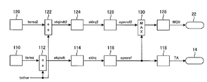
- FIG. 2 is a functional block diagram showing the configuration of the control device realized by the ECU 100 functioning according to the control program.
- the control device according to the present embodiment includes a plurality of calculation elements 110, 112, 114, 116, 118, 120, 122, 124, 126, 128, and 130, and the throttle 14 and the wastegate are calculated by calculation using these calculation elements. Each operation amount of the valve 22 is calculated.
- These arithmetic elements are elements that are virtually realized by executing the control program.
- the control device has a calculation element 110 that generates a required torque (first required torque).
- the arithmetic element 110 calculates and outputs a required torque (tereq) for the internal combustion engine 2.
- the required torque (tereq) includes the driver required torque determined according to the accelerator pedal opening and the system required torque required from various in-vehicle systems such as traction control systems and electronically controlled automatic transmissions. ing.
- the system required torque includes torque for traction control, torque for skid prevention control, torque required to maintain idle speed, torque for vehicle vibration suppression control, electronically controlled automatic transmission Various torques such as torque for shift control are included.
- the required torque (tereq) generated by the calculation element 110 is input to the calculation element 112.
- the other torque (tother) including the friction torque and the external load torque is added to the required torque (tereq), and the total value is output as the target indicated torque (etqindt) of the internal combustion engine 2.
- the target indicated torque (etqindt) calculated by the calculation element 112 is input to the calculation element 114.
- the calculation element 114 calculates the intake air amount necessary to achieve the target indicated torque (etqindt). For the calculation of the intake air amount, a map having torque and engine speed as arguments is used. The intake air amount obtained by the calculation is output as the target intake air amount (eklrq) of the internal combustion engine 2.
- the target intake air amount (eklrq) calculated by the calculation element 114 is input to the calculation element 116.
- the calculation element 116 calculates the intake pipe pressure necessary to achieve the target intake air amount (eklrq).
- an intake valve model that approximates the relationship between the intake air amount and the intake pipe pressure with a function is used.
- Each coefficient of the function representing the intake valve model is determined using a map having arguments of the valve timing of the intake valve and the exhaust valve and the opening degree of the waste gate valve.
- the intake pipe pressure obtained by the calculation is output as the target intake pipe pressure (epmref) of the internal combustion engine 2.
- the target intake pipe pressure (epmref) calculated by the calculation element 116 is input to the calculation element 118.
- the calculation element 118 calculates the throttle opening required to achieve the target intake pipe pressure (epmref).
- An air inverse model is used to calculate the throttle opening.
- the air inverse model is an inverse model of the air model in which the relationship established between the intake pipe pressure and the throttle opening is represented by a physical model.
- the air model includes a throttle model represented by a throttle equation and an intake pipe model represented by a flow rate conservation type and an energy conservation type.
- the throttle opening obtained by calculation using the air inverse model is output as the target throttle opening (TA) of the internal combustion engine 2.
- the control device operates the throttle 14 according to the target throttle opening (TA).
- the target intake pipe pressure (epmref) calculated by the calculation element 116 is also input to the calculation element 130 in parallel with the input to the calculation element 118.
- the second target intake pipe pressure (epmref2) obtained by the calculation by the calculation elements 120, 122, 124, and 126 described below is also input to the calculation element 130.
- the calculation element 120 is a calculation element that generates a warning torque (tereq2) that is the second required torque.
- the notice torque (tereq2) generated by the calculation element 120 is normally set to a lower limit value of a realizable torque, that is, an invalid value.
- the warning torque (tereq2) is an effective value only during the period corresponding to the pulse component.
- the effective value is a predicted value of the required torque (tereq) after the pulse component has passed.
- a value obtained by removing the pulse component from the current required torque (tereq) may be set as the effective value of the notice torque (tereq2).
- a specific example of the notice torque (tereq2) will be described.
- a torque down request of about 500 ms is issued from the control device for the electronically controlled automatic transmission.
- the computing element 110 generates a pulse component in the torque down direction in response to this torque down request, and adds it to the base value of the required torque (tereq).
- the computing element 120 predicts the required torque (tereq) after the end of the shift control from the accelerator pedal opening, and sets the predicted value as the warning torque (tereq2).
- the computing element 120 returns the value of the notice torque (tereq2) to an invalid value again.
- the warning torque (tereq2) generated by the calculation element 120 is input to the calculation element 122.
- the other torque (tother) including the friction torque and the external load torque is added to the warning torque (tereq2), and the total value is calculated as the second target indicated torque (etqindt2).
- the second target indicated torque (etqindt2) calculated by the calculation element 122 is input to the calculation element 124.
- the calculation element 124 calculates the intake air amount necessary to achieve the second target indicated torque (etqindt2).
- the map used for calculation of the intake air amount is the same as the map used in the calculation element 114. However, in the calculation of the intake air amount by the calculation element 124, the target engine speed that is a predicted value of the engine speed after the pulse component has passed (that is, after the shift) is used as an argument of the map, not the current engine speed. May be.
- the intake air amount obtained by the calculation is output as the second target intake air amount (eklrq2).
- the second target intake air amount (eklrq2) calculated by the calculation element 124 is input to the calculation element 126.
- the calculation element 116 calculates the intake pipe pressure necessary to achieve the second target intake air amount (eklrq2).
- the intake valve model used for calculating the intake pipe pressure is the same as the intake valve model used in the calculation element 126.
- the intake pipe pressure obtained by the calculation is output as the second target intake pipe pressure (epmref2).
- the calculation by the calculation elements 122, 124, and 126 is performed only when the notice torque (tereq2) is an effective value. When the notice torque (tereq2) is an invalid value, the calculation by the calculation elements 122, 124, 126 is stopped in order to reduce the calculation load on the ECU 100.
- the calculation element 130 compares the target intake pipe pressure (epmref) calculated by the calculation element 116 with the second target intake pipe pressure (epmref2) calculated by the calculation element 126, and selects the larger value.
- the target intake pipe pressure (epmref) is selected when the notice torque (tereq2) is an invalid value, that is, when the required torque (tereq) does not include a pulse component in the torque down direction.
- the second target intake pipe pressure (epmref2) is selected when the notice torque (tereq2) is an effective value, that is, when the required torque (tereq) includes a pulse component in the torque down direction. Therefore, when the upshift is performed in the shift control of the electronically controlled automatic transmission, the second target intake pipe pressure (epmref2) is selected by the calculation element 130.
- the target intake pipe pressure (epmref or epmref2) selected by the calculation element 130 is input to the calculation element 128.
- the computing element 128 calculates the waste gate valve opening required to achieve the selected target intake pipe pressure.
- a value obtained by adding a predetermined value ⁇ to the target intake pipe pressure is determined as the target boost pressure.
- the predetermined value ⁇ is set to a value of zero or more.
- the waste gate valve opening corresponding to the target supercharging pressure is calculated using a map or model that associates the supercharging pressure with the waste gate valve opening.
- the waste gate valve opening obtained by the calculation is the target waste gate valve opening (WGV) of the internal combustion engine 2.
- the control device operates the waste gate valve 22 according to the target waste gate valve opening (WGV).
- the operation amount of the wastegate valve 22 may be the control amount of the actuator that drives the wastegate valve (for example, the duty ratio of the solenoid) instead of the wastegate valve opening.
- a target duty ratio corresponding to the target boost pressure may be determined using a map or a model, and the waste gate valve 22 may be operated according to the target duty ratio.
- both the throttle 14 and the wastegate valve 22 in a situation where the required torque (tereq) does not include a pulse component in the torque down direction, both the throttle 14 and the wastegate valve 22 ). Therefore, when the required torque (tereq) decreases, the throttle 14 is closed and the wastegate valve 22 is opened, and when the required torque (tereq) increases, the throttle 14 is opened and the wastegate valve 22 is closed. It is done.
- the throttle 14 in a situation where the required torque (tereq) includes a pulse component in the torque down direction, the throttle 14 is operated based on the required torque (tereq), but the wastegate valve 22 is operated based on the warning torque (tereq2). Is done.
- the notice torque (tereq2) at this time is a predicted value of the required torque (tereq) in the future, and is a value obtained by removing the pulse component from the required torque (tereq). For this reason, the throttle opening changes in accordance with the pulse-like change in the required torque (tereq), while the wastegate valve opening is held at a substantially constant opening.
- FIG. 3 shows a control result when the upshift is performed in the shift control of the electronically controlled automatic transmission.
- a pulse component in the torque down direction corresponding to the shift control period from time t1 to time t2 is given to the required torque (tereq).
- the value of the notice torque (tereq2) is switched from the invalid value to the valid value corresponding to the future predicted value of the required torque (tereq).
- the target throttle opening is determined based on the required torque (tereq). Therefore, at the time of upshifting, as shown in the second chart of FIG. 3, the throttle opening is changed in accordance with the pulse-like change in the required torque (tereq).
- the target boost pressure is determined based on the required torque (tereq) outside the shift control period, but is determined based on the notice torque (tereq2) within the shift control period. Therefore, as shown in the fourth chart of FIG. 3, the target boost pressure is substantially flat and the actual boost pressure is maintained without being lowered. As a result, as shown in the third chart of FIG. 3, the intake air amount changes following the change in the throttle opening.
- the intake air amount decreases stepwise as the throttle opening stepwise decreases at time t1, and then the intake air amount also follows the increase in throttle opening stepwise at time t2. Increase in shape. Accordingly, as shown in the first chart of FIG. 3, the actual torque changes following the required torque (tereq), and a pulse-like torque change in the torque down direction is achieved.
- the wastegate valve 22 when the required torque (tereq) includes a pulse component in the torque-down direction, the wastegate valve 22 does not operate. Only the throttle 14 operates following the pulse component. For this reason, the supercharging pressure upstream of the throttle 14 is maintained without being lowered. Thus, after the torque is decreased stepwise by the operation of the throttle 14 in the closing direction, the torque can be increased stepwise by the operation of the throttle 14 in the opening direction. That is, according to the control device according to the present embodiment, it is possible to achieve, for example, a pulse-like torque change in the torque down direction that is required when the electronically controlled automatic transmission is upshifted.
- the target intake air amount (eklrq) calculated based on the required torque is compared with the second target intake air amount (eklrq2) calculated based on the notice torque, and the larger one is selected. Then, the target wastegate valve opening is calculated using the calculation elements 126 and 128 based on the selected target intake air amount. Even if it is such a modification, the effect similar to the above-mentioned embodiment can be acquired.
- the target indicated torque (etqindt) calculated based on the required torque is compared with the second target indicated torque (etqindt2) calculated based on the notice torque, and the larger one is selected. Then, the target wastegate valve opening is calculated using the calculation elements 124, 126, and 128 based on the selected target indicated torque. Even if it is such a modification, the effect similar to the above-mentioned embodiment can be acquired.
- the control device is not only an internal combustion engine having a turbocharger with a wastegate valve, but also an internal combustion engine having a variable displacement turbocharger and an internal combustion engine having a mechanical supercharger with an electromagnetic clutch.
- the present invention can also be applied to an engine or an internal combustion engine having an electric supercharger.
- any internal combustion engine having a supercharger with a control device for controlling the rotation speed of the compressor can be controlled by the control device according to the present invention.
- the throttle is regarded as the first actuator and the supercharger with the control device is regarded as the second actuator.
- the first actuator and the second actuator in the control device according to the present invention are not limited to a combination of a throttle and a supercharger with a control device.
- the intake control valve is regarded as a first actuator and the throttle is regarded as a second actuator.
- the control device according to the present invention can be applied by regarding the intake valve as a first actuator and the throttle as a second actuator. it can.
Landscapes
- Engineering & Computer Science (AREA)
- Chemical & Material Sciences (AREA)
- Combustion & Propulsion (AREA)
- Mechanical Engineering (AREA)
- General Engineering & Computer Science (AREA)
- Transportation (AREA)
- Automation & Control Theory (AREA)
- Combined Controls Of Internal Combustion Engines (AREA)
- Output Control And Ontrol Of Special Type Engine (AREA)
- Supercharger (AREA)
- Control Of Vehicle Engines Or Engines For Specific Uses (AREA)
- Electrical Control Of Air Or Fuel Supplied To Internal-Combustion Engine (AREA)
Abstract
Description
4 燃焼室
6 吸気弁
10 吸気通路
14 スロットル
20 ターボ過給機
22 ウエストゲートバルブ
100 ECU
110 要求トルク(第1の要求トルク)を生成する演算要素
116 目標吸気管圧(第1の目標状態量)を算出する演算要素
118 目標スロットル開度を算出する演算要素
120 予告トルク(第2の要求トルク)を生成する演算要素
126 第2目標吸気管圧(第2の目標状態量)を算出する演算要素
128 目標ウエストゲートバルブ開度を算出する演算要素
130 目標吸気管圧と第2目標吸気管圧のより大きい方を選択する演算要素
Claims (6)
- 内燃機関の吸気通路の第1の位置に設けられて前記第1の位置の下流の圧力に作用する第1のアクチュエータと、
前記吸気通路の第1の位置よりも上流の第2の位置に設けられて前記第2の位置の下流の圧力に作用する第2のアクチュエータと、を有する内燃機関の制御装置において、
運転者からの要求及び車載システムからの要求に基づいて前記内燃機関に対する第1の要求トルクを生成する第1要求トルク生成手段と、
前記第1の要求トルクにトルクダウン方向のパルス成分が含まれる場合、前記パルス成分を含まない第2の要求トルクを生成する第2要求トルク生成手段と、
前記第1の要求トルクに基づいて前記第1のアクチュエータを操作する第1の操作手段と、
前記第2の要求トルクの有効値が無い場合には前記第1の要求トルクに基づいて前記第2のアクチュエータを操作し、前記第2の要求トルクの有効値が有る場合には前記第2の要求トルクに基づいて前記第2のアクチュエータを操作する第2の操作手段と、
を備えることを特徴とする内燃機関の制御装置。 - 前記第2要求トルク生成手段は、前記パルス成分が過ぎた後の前記第1の要求トルクの値を予測し、その予測値を前記第2の要求トルクとして生成することを特徴とする請求項1に記載の内燃機関の制御装置。
- 前記第1の操作手段は、前記第1の要求トルクに基づいて算出した第1の目標状態量に基づいて前記第1のアクチュエータの操作量を算出し、
前記第2の操作手段は、前記第1の要求トルクに基づいて算出した第1の目標状態量と前記第2の要求トルクに基づいて算出した第2の目標状態量とを比較し、より大きい方に基づいて前記第2のアクチュエータの操作量を算出することを特徴とする請求項1又は2に記載の内燃機関の制御装置。 - 前記第1のアクチュエータは、前記第1の位置の上流の圧力に対して下流の圧力を減少させるように作用するアクチュエータであり、
前記第2のアクチュエータは、前記第2の位置の上流の圧力に対して下流の圧力を上昇させるように作用するアクチュエータであることを特徴とする請求項1乃至3の何れか1項に記載の内燃機関の制御装置。 - 前記第2のアクチュエータは、その動作に対する前記第2の位置の下流の圧力の変化速度が前記第1のアクチュエータの動作に対する前記第1の位置の下流の圧力の変化速度よりも遅いアクチュエータであることを特徴とする請求項1乃至4の何れか1項に記載の内燃機関の制御装置。
- 前記第1のアクチュエータは、スロットルであり、
前記第2のアクチュエータは、コンプレッサの回転数を制御する制御デバイス付きの過給機であることを特徴とする請求項4又は5に記載の内燃機関の制御装置。
Priority Applications (5)
| Application Number | Priority Date | Filing Date | Title |
|---|---|---|---|
| JP2014519713A JP5858156B2 (ja) | 2012-06-04 | 2012-06-04 | 内燃機関の制御装置 |
| US14/404,684 US9441558B2 (en) | 2012-06-04 | 2012-06-04 | Controller for internal combustion engines |
| EP12878573.0A EP2857660B1 (en) | 2012-06-04 | 2012-06-04 | Controller for internal combustion engines |
| CN201280073711.0A CN104334859B (zh) | 2012-06-04 | 2012-06-04 | 内燃机的控制装置 |
| PCT/JP2012/064385 WO2013183104A1 (ja) | 2012-06-04 | 2012-06-04 | 内燃機関の制御装置 |
Applications Claiming Priority (1)
| Application Number | Priority Date | Filing Date | Title |
|---|---|---|---|
| PCT/JP2012/064385 WO2013183104A1 (ja) | 2012-06-04 | 2012-06-04 | 内燃機関の制御装置 |
Publications (1)
| Publication Number | Publication Date |
|---|---|
| WO2013183104A1 true WO2013183104A1 (ja) | 2013-12-12 |
Family
ID=49711525
Family Applications (1)
| Application Number | Title | Priority Date | Filing Date |
|---|---|---|---|
| PCT/JP2012/064385 WO2013183104A1 (ja) | 2012-06-04 | 2012-06-04 | 内燃機関の制御装置 |
Country Status (5)
| Country | Link |
|---|---|
| US (1) | US9441558B2 (ja) |
| EP (1) | EP2857660B1 (ja) |
| JP (1) | JP5858156B2 (ja) |
| CN (1) | CN104334859B (ja) |
| WO (1) | WO2013183104A1 (ja) |
Cited By (4)
| Publication number | Priority date | Publication date | Assignee | Title |
|---|---|---|---|---|
| WO2015087159A1 (en) * | 2013-12-09 | 2015-06-18 | Toyota Jidosha Kabushiki Kaisha | Controller and control method for internal combustion engine |
| JP2015129469A (ja) * | 2014-01-08 | 2015-07-16 | トヨタ自動車株式会社 | 過給機付きエンジンの制御装置 |
| JP2015169147A (ja) * | 2014-03-07 | 2015-09-28 | トヨタ自動車株式会社 | 車両 |
| JP2016205282A (ja) * | 2015-04-24 | 2016-12-08 | トヨタ自動車株式会社 | 車両統合制御装置 |
Families Citing this family (3)
| Publication number | Priority date | Publication date | Assignee | Title |
|---|---|---|---|---|
| EP2857660B1 (en) * | 2012-06-04 | 2017-07-26 | Toyota Jidosha Kabushiki Kaisha | Controller for internal combustion engines |
| JP5773026B2 (ja) * | 2013-04-30 | 2015-09-02 | トヨタ自動車株式会社 | 過給機付きエンジンの制御装置 |
| JP6922311B2 (ja) * | 2017-03-23 | 2021-08-18 | 三菱自動車工業株式会社 | 車両の制御装置 |
Citations (9)
| Publication number | Priority date | Publication date | Assignee | Title |
|---|---|---|---|---|
| JPH03253747A (ja) * | 1990-03-02 | 1991-11-12 | Japan Electron Control Syst Co Ltd | ターボチャージャ搭載内燃機関のトラクション制御装置 |
| JPH05180027A (ja) * | 1991-12-26 | 1993-07-20 | Mazda Motor Corp | エンジンの制御装置 |
| JP2006274831A (ja) * | 2005-03-28 | 2006-10-12 | Denso Corp | ターボチャージャ付き内燃機関の制御装置 |
| JP2007198157A (ja) | 2006-01-24 | 2007-08-09 | Hitachi Ltd | エンジンの制御装置および制御方法 |
| JP2007292031A (ja) | 2006-04-27 | 2007-11-08 | Hitachi Ltd | エンジンの制御装置 |
| JP2007303330A (ja) * | 2006-05-10 | 2007-11-22 | Denso Corp | 過給機付き内燃機関の制御装置 |
| JP2010024908A (ja) * | 2008-07-17 | 2010-02-04 | Mazda Motor Corp | 車両用の内燃機関を制御する方法及び内燃機関システム |
| JP2010112214A (ja) | 2008-11-05 | 2010-05-20 | Toyota Motor Corp | 内燃機関の制御装置 |
| JP2010216419A (ja) | 2009-03-18 | 2010-09-30 | Toyota Motor Corp | 内燃機関の制御装置 |
Family Cites Families (7)
| Publication number | Priority date | Publication date | Assignee | Title |
|---|---|---|---|---|
| US6938420B2 (en) * | 2002-08-20 | 2005-09-06 | Nissan Motor Co., Ltd. | Supercharger for internal combustion engine |
| DE10305646B4 (de) * | 2003-02-11 | 2005-02-03 | Siemens Ag | Verfahren zur Regelung des Ladedrucks bei einer Brennkraftmaschine mit Abgasturbolader |
| JP2005048678A (ja) * | 2003-07-30 | 2005-02-24 | Nissan Motor Co Ltd | 内燃機関の燃焼制御装置 |
| US6901324B2 (en) * | 2003-09-30 | 2005-05-31 | Caterpillar Inc | System and method for predictive load management |
| JP2006125352A (ja) * | 2004-11-01 | 2006-05-18 | Denso Corp | 過給機付き内燃機関の制御装置 |
| JP4877200B2 (ja) * | 2007-11-06 | 2012-02-15 | トヨタ自動車株式会社 | 内燃機関の制御装置 |
| EP2857660B1 (en) * | 2012-06-04 | 2017-07-26 | Toyota Jidosha Kabushiki Kaisha | Controller for internal combustion engines |
-
2012
- 2012-06-04 EP EP12878573.0A patent/EP2857660B1/en not_active Not-in-force
- 2012-06-04 US US14/404,684 patent/US9441558B2/en not_active Expired - Fee Related
- 2012-06-04 JP JP2014519713A patent/JP5858156B2/ja not_active Expired - Fee Related
- 2012-06-04 CN CN201280073711.0A patent/CN104334859B/zh not_active Expired - Fee Related
- 2012-06-04 WO PCT/JP2012/064385 patent/WO2013183104A1/ja active Application Filing
Patent Citations (9)
| Publication number | Priority date | Publication date | Assignee | Title |
|---|---|---|---|---|
| JPH03253747A (ja) * | 1990-03-02 | 1991-11-12 | Japan Electron Control Syst Co Ltd | ターボチャージャ搭載内燃機関のトラクション制御装置 |
| JPH05180027A (ja) * | 1991-12-26 | 1993-07-20 | Mazda Motor Corp | エンジンの制御装置 |
| JP2006274831A (ja) * | 2005-03-28 | 2006-10-12 | Denso Corp | ターボチャージャ付き内燃機関の制御装置 |
| JP2007198157A (ja) | 2006-01-24 | 2007-08-09 | Hitachi Ltd | エンジンの制御装置および制御方法 |
| JP2007292031A (ja) | 2006-04-27 | 2007-11-08 | Hitachi Ltd | エンジンの制御装置 |
| JP2007303330A (ja) * | 2006-05-10 | 2007-11-22 | Denso Corp | 過給機付き内燃機関の制御装置 |
| JP2010024908A (ja) * | 2008-07-17 | 2010-02-04 | Mazda Motor Corp | 車両用の内燃機関を制御する方法及び内燃機関システム |
| JP2010112214A (ja) | 2008-11-05 | 2010-05-20 | Toyota Motor Corp | 内燃機関の制御装置 |
| JP2010216419A (ja) | 2009-03-18 | 2010-09-30 | Toyota Motor Corp | 内燃機関の制御装置 |
Cited By (4)
| Publication number | Priority date | Publication date | Assignee | Title |
|---|---|---|---|---|
| WO2015087159A1 (en) * | 2013-12-09 | 2015-06-18 | Toyota Jidosha Kabushiki Kaisha | Controller and control method for internal combustion engine |
| JP2015129469A (ja) * | 2014-01-08 | 2015-07-16 | トヨタ自動車株式会社 | 過給機付きエンジンの制御装置 |
| JP2015169147A (ja) * | 2014-03-07 | 2015-09-28 | トヨタ自動車株式会社 | 車両 |
| JP2016205282A (ja) * | 2015-04-24 | 2016-12-08 | トヨタ自動車株式会社 | 車両統合制御装置 |
Also Published As
| Publication number | Publication date |
|---|---|
| CN104334859B (zh) | 2016-11-23 |
| EP2857660B1 (en) | 2017-07-26 |
| JPWO2013183104A1 (ja) | 2016-01-21 |
| EP2857660A1 (en) | 2015-04-08 |
| EP2857660A4 (en) | 2016-06-08 |
| CN104334859A (zh) | 2015-02-04 |
| US9441558B2 (en) | 2016-09-13 |
| US20150101569A1 (en) | 2015-04-16 |
| JP5858156B2 (ja) | 2016-02-10 |
Similar Documents
| Publication | Publication Date | Title |
|---|---|---|
| JP5858156B2 (ja) | 内燃機関の制御装置 | |
| US6279531B1 (en) | System and method for controlling engine torque | |
| JPWO2014010067A1 (ja) | ターボ過給機付き内燃機関の制御装置 | |
| WO2013005303A1 (ja) | 過給機付き内燃機関の制御装置 | |
| US9115643B2 (en) | Control device for internal combustion engine with supercharger | |
| JP6477290B2 (ja) | 内燃機関の制御装置 | |
| JP5999056B2 (ja) | 車両の制御装置 | |
| JP5920176B2 (ja) | 内燃機関の制御装置 | |
| JP5999180B2 (ja) | 車両統合制御装置 | |
| JP2007046502A (ja) | エンジンの制御装置 | |
| JP6089937B2 (ja) | エンジンの制御装置 | |
| CN108716436B (zh) | 车辆控制装置 | |
| JP7312373B2 (ja) | エンジンの制御装置 | |
| JP7265724B2 (ja) | エンジンの制御装置 | |
| JP2013241896A (ja) | 過給機付き内燃機関の制御装置 | |
| JP4911112B2 (ja) | エンジンの制御装置 | |
| WO2022064237A1 (ja) | 内燃機関の制御方法および制御装置 | |
| JP5525430B2 (ja) | 内燃機関の制御装置 | |
| JP2008280979A (ja) | 内燃機関の吸気制御装置 | |
| JP2017082691A (ja) | 車両のエンジン制御装置 | |
| JP2013170515A (ja) | 内燃機関の制御装置 | |
| JP2014152738A (ja) | エンジンの制御装置 | |
| JP2011247113A (ja) | 内燃機関の吸入空気量制御方法 | |
| JPWO2013005303A1 (ja) | 過給機付き内燃機関の制御装置 |
Legal Events
| Date | Code | Title | Description |
|---|---|---|---|
| 121 | Ep: the epo has been informed by wipo that ep was designated in this application |
Ref document number: 12878573 Country of ref document: EP Kind code of ref document: A1 |
|
| ENP | Entry into the national phase |
Ref document number: 2014519713 Country of ref document: JP Kind code of ref document: A |
|
| REEP | Request for entry into the european phase |
Ref document number: 2012878573 Country of ref document: EP |
|
| WWE | Wipo information: entry into national phase |
Ref document number: 2012878573 Country of ref document: EP |
|
| WWE | Wipo information: entry into national phase |
Ref document number: 14404684 Country of ref document: US |
|
| NENP | Non-entry into the national phase |
Ref country code: DE |