WO2013157451A1 - 有機電界発光素子及びその製造方法 - Google Patents
有機電界発光素子及びその製造方法 Download PDFInfo
- Publication number
- WO2013157451A1 WO2013157451A1 PCT/JP2013/060755 JP2013060755W WO2013157451A1 WO 2013157451 A1 WO2013157451 A1 WO 2013157451A1 JP 2013060755 W JP2013060755 W JP 2013060755W WO 2013157451 A1 WO2013157451 A1 WO 2013157451A1
- Authority
- WO
- WIPO (PCT)
- Prior art keywords
- group
- layer
- compound
- organic electroluminescent
- organic
- Prior art date
Links
- 0 CCC1(C)C(CC)(C2CC2)*(CI)CCC1 Chemical compound CCC1(C)C(CC)(C2CC2)*(CI)CCC1 0.000 description 1
Images


Classifications
-
- H—ELECTRICITY
- H10—SEMICONDUCTOR DEVICES; ELECTRIC SOLID-STATE DEVICES NOT OTHERWISE PROVIDED FOR
- H10K—ORGANIC ELECTRIC SOLID-STATE DEVICES
- H10K50/00—Organic light-emitting devices
- H10K50/10—OLEDs or polymer light-emitting diodes [PLED]
- H10K50/17—Carrier injection layers
-
- H—ELECTRICITY
- H10—SEMICONDUCTOR DEVICES; ELECTRIC SOLID-STATE DEVICES NOT OTHERWISE PROVIDED FOR
- H10K—ORGANIC ELECTRIC SOLID-STATE DEVICES
- H10K85/00—Organic materials used in the body or electrodes of devices covered by this subclass
- H10K85/10—Organic polymers or oligomers
- H10K85/151—Copolymers
-
- H—ELECTRICITY
- H10—SEMICONDUCTOR DEVICES; ELECTRIC SOLID-STATE DEVICES NOT OTHERWISE PROVIDED FOR
- H10K—ORGANIC ELECTRIC SOLID-STATE DEVICES
- H10K85/00—Organic materials used in the body or electrodes of devices covered by this subclass
- H10K85/30—Coordination compounds
- H10K85/321—Metal complexes comprising a group IIIA element, e.g. Tris (8-hydroxyquinoline) gallium [Gaq3]
- H10K85/322—Metal complexes comprising a group IIIA element, e.g. Tris (8-hydroxyquinoline) gallium [Gaq3] comprising boron
Definitions
- the present invention relates to an organic electroluminescent device and a method for manufacturing the same. More specifically, the present invention relates to an organic electroluminescent element that can be used as a display device such as a display unit of an electronic device, a lighting device, or the like, and a method for manufacturing the same.
- organic electroluminescent element is expected as a new light emitting element applicable to a display device or illumination.
- Organic electroluminescent elements are thin, flexible, and flexible, and when used as display devices, they have higher brightness and higher definition than liquid crystal and plasma display devices that are currently mainstream. Display, and has excellent features such as a wider viewing angle than liquid crystal display devices, so it is expected to be used as a display for televisions and mobile phones and as a lighting device in the future.
- An organic EL element has a structure in which one or more layers including a light emitting layer formed by containing a light emitting organic compound are sandwiched between an anode and a cathode, and is injected from holes and cathodes injected from the anode.
- the light-emitting organic compound is excited using the energy when the generated electrons recombine to obtain light emission.
- An organic EL element is a current-driven element, and in order to make more efficient use of a flowing current, various element structures have been improved, and various layers of materials constituting the element have been studied.
- the organic electroluminescent element has a structure in which a plurality of layers such as an electron transport layer, a light emitting layer, and a hole transport layer are laminated between a cathode and an anode, and is a material suitable for constituting each layer.
- a light-emitting material including a compound having a specific structure having a boron atom is disclosed (see Patent Document 1).
- a compound having a specific structure having a boron atom is suitable as a hole blocking layer of an organic electroluminescence device (see Patent Document 2).
- organic electroluminescent device that emits light by exciting the light-emitting organic compound by utilizing the energy at the time of recombination of holes injected from the anode and electrons injected from the cathode
- hole injection from the anode, cathode Since it is important that both the electron injection from the surface is performed smoothly, various materials for the hole injection layer and the electron injection layer have been studied so that the hole injection and electron injection can be performed more smoothly.
- organic electroluminescent devices having a forward structure using polyethyleneimine or a compound modified with polyethyleneimine as a material for the electron injection layer (see Non-Patent Documents 1 to 3).
- the organic electroluminescent element in which the layers between the cathode and the anode are all formed of an organic compound is likely to be deteriorated by oxygen or water as a result, and strict sealing is indispensable to prevent these intrusions. This causes a complicated manufacturing process of the organic electroluminescent element.
- an organic-inorganic hybrid electroluminescent element (HOILED element) in which a part of a layer between a cathode and an anode is formed of an inorganic oxide has been proposed (see Patent Document 3).
- this element by changing the hole transport layer and the electron transport layer to inorganic oxides, it became possible to use FTO or ITO which is a conductive oxide electrode as a cathode and gold as an anode.
- FTO or ITO which is a conductive oxide electrode
- gold an anode.
- a metal having a small work function such as an alkali metal or an alkali metal compound, and light can be emitted without strict sealing.
- this HOILED element is characterized in that the cathode is directly above the substrate, and the reverse structure is such that the anode comes to the upper electrode.
- Conventional organic-inorganic hybrid type organic electroluminescent elements include an anode and a cathode, one or more organic compound layers sandwiched between the anode and the cathode, and between the anode and the organic compound layer.
- An organic thin film light emitting device having at least one metal oxide thin film between the cathode and the organic compound layer is disclosed (see Patent Document 4).
- an organic thin-film electroluminescent device having a metal oxide thin film and having a self-assembled monolayer that has one or more layers between each layer as an energy barrier for main carriers and no energy barrier for opposite carriers.
- an organic-inorganic hybrid organic electroluminescent element (see Non-Patent Document 4) having a structure in which a polyvinyl carbazole polymer added with an iridium compound as a dopant is laminated on a metal oxide layer, and poly (9,
- An organic-inorganic hybrid organic electroluminescent element (see Non-Patent Document 5) using a light emitting layer obtained by adding an iridium compound to 9-dioctylfluorenyl-2,7-diyl) is disclosed.
- organic-inorganic hybrid organic electroluminescent elements as well as organic electroluminescent elements in which each layer constituting the organic electroluminescent element is composed of an organic material.
- the organic / inorganic hybrid organic electroluminescent device is considered to be capable of having both the flexibility and moldability of the organic component and the strength and durability of the inorganic component. Compared to the organic electroluminescence device that has been constructed, it has higher resistance to oxygen and water, reducing the need to tightly seal each layer inside the device, and has advantages such as less labor at the time of production. Is expected.
- the organic / inorganic hybrid type organic electroluminescent element has room for improvement in various characteristics such as light emitting characteristics as compared with the organic electroluminescent element in which each layer constituting the organic electroluminescent element is composed of organic substances. Furthermore, development of an organic-inorganic hybrid organic electroluminescent device having further improved characteristics such as light emission characteristics is demanded.
- a method of laminating a plurality of types of low-molecular compound layers by a method such as vacuum vapor deposition, or a guest molecule in a host molecule is demanded.
- the structure of organic / inorganic hybrid organic electroluminescent devices that have been studied conventionally has been mainly formed by coating a polymer compound as a light emitting layer.
- the present inventor uses a low molecular weight compound as a material for forming a light emitting layer, a hole transporting layer, etc. in order to improve the light emitting characteristics of the organic-inorganic hybrid type organic electroluminescent element, such as vacuum deposition.
- Various studies were made on the form of laminating a plurality of types of low-molecular compound layers by the method and the form of doping guest molecules in host molecules.
- the injection of electrons from the cathode is less than the injection of holes from the anode, and the holes injected from the anode cannot be fully utilized for light emission. There is a problem.
- good physical and electrical contact over a long period of time between the inorganic layer and the organic layer is inherently difficult, which leads to a short life of the device and is a major problem.
- Organic electroluminescent elements which are expected to be used more widely in applications such as display devices and lighting devices, are also an important factor for their ease of manufacture, so organic-inorganic hybrid organic electric fields that do not require strict sealing Expectations for light emitting devices are high, and a method for further increasing the light emission efficiency and lifetime of organic-inorganic hybrid organic electroluminescent devices is required.
- a HOILED element having an inverse structure is useful on a circuit, and its development is awaited.
- the present invention has been made in view of the above-mentioned present situation. (1) Even when a low molecular compound layer is used as a layer constituting an organic electroluminescence device, crystallization of the low molecular compound is suppressed, and the light emission characteristics are excellent. To provide an organic / inorganic hybrid type organic electroluminescent device, and (2) To provide an organic / inorganic hybrid type organic electroluminescent device that is further superior in light emission characteristics than the conventional organic / inorganic hybrid type organic electroluminescent device. And (3) An object of the present invention is to provide an organic electroluminescence device which is easy to produce and has excellent luminous efficiency and lifetime.
- the present inventor has provided a buffer layer formed of an organic compound on the metal oxide layer. It has been found that the above-mentioned problems can be solved by having the above.
- the buffer layer here refers to the crystallization of organic layers such as the light-emitting layer, low electron injection ability, and long-term physical and chemical stability of the interface, which are the problems of the organic-inorganic hybrid organic electroluminescence device described above. It is a layer to do. Specifically, in order to prevent crystallization due to unevenness existing on the oxide surface, a higher molecular weight organic substance is suitable.
- the energy level up to the light emitting layer is preferred. It is preferable to form the positions in a staircase shape, and furthermore, by means such as doping to smooth the pumping of energy that exists as a problem peculiar to the inverse structure (up the energy staircase (uphill)) It is more preferable to increase the number of carriers.
- there is a method of generating an interface dipole by arranging a large amount of nitrogen element on the surface which is also preferable. And in order to make these exist stably for a long period of time, it is suitable to prepare the chemical bond which can prevent or withstand the presence of a local electric field.
- the former is a wide energy level change due to an increase in the number of carriers realized by a technique such as doping, and a step-like well-balanced electron level formation.
- the latter is a chemical bond between the buffer layer organic substance and the metal element on the oxide surface. Specific examples are described below.
- the present inventor examined a solution to a new problem of crystallization of a low molecular compound layer, which was found during various studies on methods for improving the light emission characteristics of an organic-inorganic hybrid type organic electroluminescent device.
- a buffer layer of a predetermined thickness formed by applying an organic compound is placed between the oxide layer formed on the cathode and a low-molecular compound layer such as a light-emitting layer, and light is emitted on this buffer layer.
- a low molecular compound layer such as a layer
- crystallization of the low molecular compound in the low molecular compound layer is suppressed, whereby an organic-inorganic hybrid type organic electroluminescent device can be used as a light emitting layer from a low molecular compound. It has been found that even when a layer is formed, it is possible to suppress leakage current and obtain uniform surface light emission. Furthermore, when the present inventors use a boron-containing compound or boron-containing polymer having a specific structure as the organic compound forming the buffer layer, the buffer layer formed from the organic compound has an excellent function as an electron transport layer.
- the present inventor has conducted various studies on methods for improving the light emission characteristics of the organic-inorganic hybrid type organic electroluminescent device, and has a metal oxide layer between the first electrode and the second electrode, An organic electroluminescent device having a buffer layer formed of an organic compound on a metal oxide layer.
- a reducing agent is included in the buffer layer of the organic electroluminescent device, the reducing agent supplies electrons. It has been found that the organic electroluminescence device works as a dopant and has excellent light emission characteristics as compared with a conventional organic-inorganic hybrid organic electroluminescence device.
- a first metal oxide layer, a buffer layer, a low-molecular compound layer including a light emitting layer stacked on the buffer layer, and a second metal oxide between the first electrode and the second electrode It has also been found that an organic electroluminescence device having a structure having physical layers in this order and an organic electroluminescence device in which a reducing agent is included in the buffer layer of the organic electroluminescence device is suitable. Furthermore, the present inventor has made various studies on methods for further increasing the light emission efficiency and life of the organic-inorganic hybrid organic electroluminescent device that does not require strict sealing.
- the metal oxide layer between the anode and the cathode It has been found that when a nitrogen-containing film having a predetermined thickness is formed thereon, the electron injection characteristics are improved and the device has a longer life.
- a nitrogen-containing film having a high nitrogen atom ratio in the atoms constituting the nitrogen-containing film or a nitrogen-containing film formed by a method of decomposing a nitrogen-containing compound to form a nitrogen-containing film may be more preferable.
- the inventors found that a material formed by decomposition of a nitrogen-containing compound and having a high nitrogen atom ratio in atoms constituting the nitrogen-containing film is more preferable.
- the present inventor uses such a nitrogen-containing film as a layer constituting an organic / inorganic hybrid type organic electroluminescence device, the present inventor not only has excellent luminous efficiency but also has high driving stability and long driving life. As a result, the inventors have found that the device can be solved, and that they can solve the above-mentioned problems in a brilliant manner, thereby achieving the present invention.
- the present invention is an organic electroluminescent device having a structure in which a plurality of layers are laminated, and the organic electroluminescent device has a metal oxide layer between a first electrode and a second electrode.
- An organic electroluminescence device comprising a buffer layer formed of an organic compound on the metal oxide layer.
- Layer, a low molecular compound layer including a light emitting layer stacked on the buffer layer, and a second metal oxide layer in this order, and the buffer layer is formed by applying a solution containing an organic compound.
- An organic electroluminescent device characterized by having an average thickness of 5 to 50 nm is a first preferred form of the organic electroluminescent device of the present invention. Furthermore, the organic electroluminescent device has a structure in which a plurality of layers are laminated, and the organic electroluminescent device includes a first metal oxide layer, a buffer between the first electrode and the second electrode.
- the light emitting element is a second preferred form of the organic electroluminescent element of the present invention.
- an organic electroluminescence device having a structure in which a plurality of layers are laminated between an anode and a cathode formed on a substrate, wherein the organic electroluminescence device includes a metal oxide layer between the anode and the cathode.
- An organic electroluminescent device comprising a physical layer, comprising a nitrogen-containing film on the metal oxide layer and having an average thickness of 3 to 150 nm, is an organic electroluminescent device according to the present invention.
- the third preferred form. The present invention is described in detail below. A combination of two or more preferred embodiments of the present invention described below is also a preferred embodiment of the present invention.
- the organic electroluminescent element of the present invention is an organic electroluminescent element having a structure in which a plurality of layers are laminated, and has a metal oxide layer between a first electrode and a second electrode, and the metal A buffer layer formed of an organic compound is provided over the oxide layer.
- the first electrode is a cathode formed on a substrate, and has a metal oxide layer and a buffer layer formed of an organic compound in this order between the second electrode and the anode. This is a preferred form of the electroluminescent element.
- the buffer layer is a layer having an average thickness of 3 nm or more formed by applying a solution containing an organic compound, and the buffer layer is formed adjacent to the metal oxide layer. This is a preferred form of the organic electroluminescent element.
- the organic electroluminescent element of the present invention has three preferred forms with different element layer configurations and buffer layers. In the following, these three preferred modes will be described in order. In addition, it is also a suitable form of the organic electroluminescent element of this invention that corresponds to two or more of these three suitable forms.
- An organic electroluminescent element according to a first preferred embodiment of the present invention includes a first metal between a first electrode and a second electrode.
- An oxide layer, a buffer layer, a low-molecular compound layer including a light-emitting layer stacked on the buffer layer, and a second metal oxide layer in this order, and an average thickness of the buffer layer is 3 nm It is. Furthermore, the average thickness of the buffer layer is preferably 5 to 50 nm.
- the buffer layer has an electron level such that the order of the electron level of each layer from the electrode formed on the substrate to the light emitting layer is the stacking order of these layers. . Since the first organic electroluminescent element of the present invention has such a configuration, even when the layer constituting the organic electroluminescent element such as the light emitting layer is a low molecular compound layer, the low molecular compound layer is crystallized. Can be suppressed, leakage current can be suppressed, and uniform surface emission can be obtained. In the organic-inorganic hybrid type organic electroluminescence device, the cause of the crystallization of the low molecular compound layer is considered as follows.
- a first electrode disposed on a substrate such as glass and a first metal oxide layer are present, and a low molecular compound layer including a light emitting layer is formed thereon. Will be a film.
- the first metal oxide layer is formed by a spray pyrolysis method, a sol-gel method, a sputtering method, or the like, and the surface is not smooth but has irregularities.
- the problems peculiar to the organic-inorganic hybrid type organic electroluminescent device can be solved.
- the first organic electroluminescent element of the present invention has the above-mentioned preferable structure, an average thickness formed from the first metal oxide layer and the organic compound between the first electrode and the second electrode.
- a buffer layer having a thickness of 5 to 50 nm As long as it has a buffer layer having a thickness of 5 to 50 nm, a low-molecular compound layer including a light-emitting layer laminated on the buffer layer, and a second metal oxide layer in this order, other layers other than these You may have.
- the low molecular compound means a compound that is not a polymer compound (polymer), and does not necessarily mean a compound having a low molecular weight.
- the low molecular compound layer including the light emitting layer is a layer in which one layer formed of a low molecular compound or a plurality of layers formed of low molecular compounds are stacked, and one of the layers emits light. What is a layer. That is, a low molecular compound layer including a light emitting layer is a light emitting layer formed of a low molecular compound, or a light emitting layer formed of a low molecular compound and another layer formed of a low molecular compound.
- the other layer formed by the low molecular compound may be one layer or two or more layers. The order in which the light emitting layer and other layers are stacked is not particularly limited.
- the other layer formed of the low molecular compound is preferably a hole transport layer or an electron transport layer. That is, when the low molecular compound layer is composed of a plurality of layers, it is preferable to have a hole transport layer and / or an electron transport layer as other layers other than the light emitting layer.
- the organic electroluminescent device having the hole transport layer and / or the electron transport layer as an independent layer different from the light emitting layer is a preferred embodiment of the first organic electroluminescent device of the present invention.
- the 1st organic electroluminescent element of this invention has a positive hole transport layer as an independent layer, it is preferable to have a positive hole transport layer between a light emitting layer and a 2nd metal oxide layer.
- the 1st organic electroluminescent element of this invention has an electron carrying layer as an independent layer, it is preferable to have an electron carrying layer between the buffer layer and light emitting layer which are formed from an organic compound.
- the first organic electroluminescent element of the present invention does not have a hole transport layer or an electron transport layer as an independent layer, any of the layers included as an essential component of the first organic electroluminescent element of the present invention , It will also function as these layers.
- the organic electroluminescence device comprises a first electrode, a first metal oxide layer, a buffer layer formed from an organic compound, a light emitting layer, a positive electrode. It consists only of a hole transport layer, a second metal oxide layer, and a second electrode, and any one of these layers also functions as an electron transport layer.
- the organic electroluminescent element includes only the first electrode, the first metal oxide layer, the buffer layer formed from the organic compound, the light emitting layer, the second metal oxide layer, and the second electrode. A form in which any one of these layers also serves as a hole transport layer and an electron transport layer is also a preferred form of the first organic electroluminescent element of the present invention.
- the first electrode is a cathode and the second electrode is an anode.
- a known conductive material can be appropriately used as the anode and the cathode, but at least one of them is preferably transparent for light extraction.
- Examples of known transparent conductive materials include ITO (tin-doped indium oxide), ATO (antimony-doped indium oxide), IZO (indium-doped zinc oxide), AZO (aluminum-doped zinc oxide), FTO (fluorine-doped indium oxide), Examples thereof include oxides such as In 3 O 3 , SnO 2 , Sb-containing SnO 2 , and Al-containing ZnO.
- Examples of the opaque conductive material include calcium, magnesium, aluminum, tin, indium, copper, silver, gold, platinum, and alloys thereof. Among these, ITO, IZO, and FTO are preferable as the cathode.
- anode examples include Au, Pt, Ag, Cu, Al, and alloys containing these. Among these, Au, Ag, and Al are preferable.
- the metal generally used for the anode can be used for the cathode and the anode, it is possible to easily realize light extraction from the upper electrode (in the case of a top emission structure).
- Various selections can be made for each electrode. For example, Al is used for the lower electrode and ITO is used for the upper electrode.
- the average thickness of the first electrode is not particularly limited, but is preferably 10 to 500 nm. More preferably, it is 100 to 200 nm.
- the average thickness of the first electrode can be measured by a stylus profilometer or spectroscopic ellipsometry.
- the average thickness of the second electrode is not particularly limited, but is preferably 10 to 1000 nm. More preferably, it is 30 to 150 nm. Even when an opaque material is used, for example, by setting the average thickness to about 10 to 30 nm, it can be used as a top emission type or transparent type anode.
- the average thickness of the second electrode can be measured at the time of film formation by a crystal oscillator thickness meter.
- the first metal oxide layer functions as an electron injection layer or an electrode (cathode), and the second metal oxide layer functions as a hole injection layer.
- Metal elements constituting the metal oxide include magnesium, calcium, strontium, barium, titanium, zirconium, hafnium, vanadium, niobium, tantalum, chromium, molybdenum, tungsten, manganese, indium, gallium, iron, cobalt, nickel, copper , Zinc, cadmium, aluminum, silicon, and tin.
- At least one of the metal elements constituting the laminated or mixed metal oxide layer is a layer made of magnesium, aluminum, calcium, zirconium, hafnium, silicon, titanium, zinc, tin, and among them, a simple substance Metal oxides selected from the group consisting of magnesium oxide, tungsten oxide, niobium oxide, iron oxide, aluminum oxide, zirconium oxide, hafnium oxide, silicon oxide, titanium oxide, zinc oxide and tin oxide. It is preferable.
- Examples of the layer obtained by laminating and / or mixing the single substance or two or more kinds of metal oxides include titanium oxide / zinc oxide, titanium oxide / magnesium oxide, titanium oxide / zirconium oxide, titanium oxide / aluminum oxide, titanium oxide / Lamination and / or combination of metal oxides such as hafnium oxide, titanium oxide / silicon oxide, zinc oxide / magnesium oxide, zinc oxide / zirconium oxide, zinc oxide / hafnium oxide, zinc oxide / silicon oxide, calcium oxide / aluminum oxide Mixed, titanium oxide / zinc oxide / magnesium oxide, titanium oxide / zinc oxide / zirconium oxide, titanium oxide / zinc oxide / aluminum oxide, titanium oxide / zinc oxide / hafnium oxide, titanium oxide / zinc oxide / silicon oxide, Such as indium oxide / gallium oxide / zinc oxide Like those laminating and / or mixing a combination of species of metal oxides.
- IGZO which is an oxide semiconductor that exhibits good characteristics as a special composition
- 12CaO.7Al 2 O 3 which is an electride.
- an object having a sheet resistance lower than 100 ⁇ / ⁇ is classified as a conductor, and an object having a sheet resistance higher than 100 ⁇ / ⁇ is classified as a semiconductor or an insulator.
- ITO in-doped indium oxide
- ATO antimony-doped indium oxide
- IZO indium-doped zinc oxide
- AZO aluminum-doped zinc oxide
- FTO fluorine-doped indium oxide
- the second metal oxide layer is not particularly limited, but one type of vanadium oxide (V 2 O 5 ), molybdenum oxide (MoO 3 ), tungsten oxide (WO 3 ), ruthenium oxide (RuO 2 ), or the like or Two or more kinds can be used. Among these, those containing vanadium oxide or molybdenum oxide as a main component are preferable.
- the second metal oxide layer is composed mainly of vanadium oxide or molybdenum oxide, the second metal oxide layer injects holes from the second electrode and emits light or transports holes. It becomes more excellent by the function as a hole injection layer of transporting to a layer.
- vanadium oxide or molybdenum oxide itself has a high hole transport property, it is also possible to suitably prevent the efficiency of hole injection from the second electrode to the light emitting layer or the hole transport layer from being lowered. There is an advantage that you can. More preferably, it is composed of vanadium oxide and / or molybdenum oxide.
- the average thickness of the first metal oxide layer can be tolerated from 1 nm to several ⁇ m and is not particularly limited, but is preferably 1 to 1000 nm from the viewpoint of an organic electroluminescent device that can be driven at a low voltage. . More preferably, it is 2 to 100 nm.
- the average thickness of the second metal oxide layer is not particularly limited, but is preferably 1 to 1000 nm. More preferably, it is 5 to 50 nm.
- the average thickness of the first metal oxide layer can be measured by a stylus profilometer or spectroscopic ellipsometry.
- the average thickness of the second metal oxide layer can be measured at the time of film formation with a crystal oscillator thickness meter.
- any low molecular weight compound that can be usually used as a material for the light emitting layer can be used, or a mixture thereof may be used.
- a low molecular weight type a tricoordinate iridium complex having 2,2′-bipyridine-4,4′-dicarboxylic acid as a ligand, factory (2-phenylpyridine) iridium (Ir (ppy) 3 ), 8-hydroxyquinoline aluminum (Alq 3 ), tris (4-methyl-8 quinolinolate) aluminum (III) (Almq 3 ), 8-hydroxyquinoline zinc (Znq 2 ), (1,10-phenanthroline) -tris- (4,4,4-trifluoro-1- (2-thienyl) -butane-1,3-dionate) europium (III) (Eu (TTA) 3 (phen)), 2,3,7,8,12 , 13, 17, 18-octaethyl-21H, 23H-
- the light emitting layer may contain a dopant.
- a dopant any compound that can be usually used as a dopant can be used.
- compounds that can be used as dopants include iridium compounds; low molecular organic compounds such as 4,4′-bis (9-ethyl-3-carbazovinylene) -1,1′-biphenyl (BCzVBi), and the like. These 1 type (s) or 2 or more types can be used.
- the content of the dopant is preferably 0.5 to 20% by mass with respect to 100% by mass of the material forming the light emitting layer. With such a content, the light emission characteristics can be improved. More preferably, it is 0.5 to 10% by mass, and still more preferably 1 to 6% by mass.
- the average thickness of the light emitting layer is not particularly limited, but is preferably 10 to 150 nm. More preferably, it is 20 to 100 nm. More preferably, it is 40 to 100 nm.
- the average thickness of the light emitting layer can be measured with a quartz oscillator film thickness meter in the case of a low molecular compound, and with a contact type step meter in the case of a polymer compound.
- any low molecular weight compound that can be usually used as the material for the hole transport layer can be used, or a mixture of these may be used.
- Low molecular weight compounds include reel cycloalkane compounds, arylamine compounds, phenylenediamine compounds, carbazole compounds, stilbene compounds, oxazole compounds, triphenylmethane compounds, pyrazoline compounds, benzine (cyclohexadiene) compounds.
- arylamine compounds such as N, N′-di (1-naphthyl) -N, N′-diphenyl-1,1′-biphenyl-4,4′-diamine ( ⁇ -NPD) and TPTE Is preferred.
- the average thickness of the hole transport layer is not particularly limited, but is preferably 10 to 150 nm. More preferably, it is 20 to 100 nm, and still more preferably 40 to 100 nm.
- the average thickness of the hole transport layer can be measured at the time of film formation with a crystal oscillator thickness meter.
- any low molecular weight compound that can be usually used as the material for the electron transport layer can be used, or a mixture of these may be used.
- the low molecular weight compound that can be used as the material for the electron transport layer include a boron-containing compound represented by the formula (1) described later, a pyridine derivative, a quinoline derivative, a pyrimidine derivative, a pyrazine derivative, a phenanthroline derivative, and a triazine.
- Derivatives triazole derivatives, oxazole derivatives, oxadiazole derivatives, imidazole derivatives, aromatic tetracarboxylic anhydrides, bis [2- (2-hydroxyphenyl) benzothiazolate] zinc (Zn (BTZ) 2 ), tris (8-hydroxy) Examples thereof include various metal complexes represented by quinolinato) aluminum (Alq 3 ) and the like, organosilane derivatives represented by silole derivatives, and the like, and one or more of these can be used.
- a metal complex such as Alq 3 and a pyridine derivative such as tris-1,3,5- (3 ′-(pyridin-3 ′′ -yl) phenyl) benzene (TmPyPhB) are preferable.
- the average thickness of the electron transport layer is not particularly limited, but is preferably 10 to 150 nm. More preferably, it is 20 to 100 nm, and still more preferably 40 to 100 nm.
- the average thickness of the electron transport layer can be measured at the time of film formation with a crystal oscillator thickness meter.
- the method for forming the first and second metal oxide layers, the second electrode, the light emitting layer, the hole transport layer, and the electron transport layer is not particularly limited.
- Chemical vapor deposition (CVD) such as plasma CVD, thermal CVD, and laser CVD, which is a phase deposition method
- dry plating methods such as vacuum deposition, sputtering, ion plating, thermal spraying, and electrolytic plating, which is a liquid phase deposition method
- Printing technology such as wet plating methods such as immersion plating and electroless plating, sol-gel method, MOD method, spray pyrolysis method, doctor blade method using fine particle dispersion, spin coating method, ink jet method, screen printing method, etc.
- An atomic layer deposition (ALD) method or the like can be used, and an appropriate method according to the material can be selected and used.
- the buffer layer included in the first organic electroluminescent element of the present invention is a layer formed by applying a solution containing an organic compound.
- the method for applying the solution containing the organic compound is not particularly limited, and spin coating method, casting method, micro gravure coating method, gravure coating method, bar coating method, roll coating method, wire bar coating method, slit coating method, dip coating.
- Various coating methods such as a coating method, a spray coating method, a screen printing method, a flexographic printing method, an offset printing method, and an inkjet printing method can be used.
- the spin coat method is preferable.
- the solvent used for preparing the solution containing the organic compound is not particularly limited as long as it can dissolve the organic compound.
- THF, toluene, and chloroform are preferable.
- the solution containing the organic compound preferably has a concentration of the organic compound in the solvent of 0.05 to 10% by mass. With such a concentration, it is possible to suppress the occurrence of uneven coating and unevenness when applied.
- concentration of the organic compound in the solvent is more preferably 0.1 to 5% by mass, still more preferably 0.1 to 3% by mass.
- the buffer layer preferably has an electron level such that the order of the electron level of each layer from the electrode formed on the substrate to the light emitting layer is the stacking order of these layers.
- the order of the electron level height of each layer from the electrode (cathode) to the light emitting layer formed on the substrate is the same as the stacking order, and the height of the electron level from the electrode (cathode) to the light emitting layer is By increasing in steps, electron transfer from the electrode (cathode) to the light emitting layer is performed relatively smoothly even in the uphill.
- the buffer layer preferably has an average thickness of 5 to 50 nm.
- the average thickness is within such a range, the effect of suppressing crystallization of the low molecular compound layer including the light emitting layer can be sufficiently exhibited.
- the average thickness of the buffer layer is less than 5 nm, the unevenness present on the surface of the first metal oxide cannot be sufficiently smoothed, and the leakage current increases and the effects of the present invention cannot be fully exhibited. There is.
- the average thickness of the buffer layer is larger than 50 nm, the driving voltage is increased, which is not practically preferable.
- a buffer layer can fully exhibit the function as an electron carrying layer.
- the average thickness of the buffer layer is more preferably 10 to 30 nm.
- the average thickness of the buffer layer can be measured by a stylus profilometer or spectroscopic ellipsometry.
- the above-mentioned JP2012-4492A includes an anode, a cathode, one or more organic compound layers sandwiched between the anode and the cathode, and an anode and an organic compound layer. At least one metal oxide thin film is provided between or between the cathode and the organic compound layer, and one or a plurality of layers between each of them is an energy barrier for the main carrier, and an energy barrier for the opposite carrier.
- An organic thin film electroluminescent device having a self-assembled monomolecular film that has not been disclosed is disclosed.
- the patent document discloses that a self-assembled monomolecular film having a specific energy level is formed on an oxide substrate (by a film forming method including coating), Describes an element configuration in which reverse carriers are injected by tunneling. Further, it is described that carrier injection by tunneling preferably functions when the self-assembled monolayer is a thin film of 2 nm or less (from the description of Patent Document 5, the average thickness of the organic compound layer is 2 nm or less). It is estimated to be). On the other hand, as will be described in Examples below, the average thickness of the organic compound layer needs to be 5 nm or more in order to obtain a sufficient effect for the problem to be solved by the present invention. . Thus, the present invention and the invention disclosed in Patent Document 5 are essentially different from each other in the problems to be solved and the means for solving them, and should be clearly distinguished.
- the first organic electroluminescent element of the present invention may be one in which each layer constituting the organic electroluminescent element is laminated on a substrate. When each layer is laminated on the substrate, it is preferable that each layer is formed on the first electrode formed on the substrate.
- the first organic electroluminescence device of the present invention may be a top emission type that extracts light to the side opposite to the side where the substrate is present, or a bottom emission type that extracts light to the side where the substrate is present. It may be a thing.
- resin materials such as polyethylene terephthalate, polyethylene naphthalate, polypropylene, cycloolefin polymer, polyamide, polyethersulfone, polymethyl methacrylate, polycarbonate, polyarylate, quartz glass, soda glass, etc.
- a glass material etc. are mentioned, These 1 type (s) or 2 or more types can be used.
- an opaque substrate can be used.
- an oxide film is formed on the surface of a ceramic substrate such as alumina or a metal substrate such as stainless steel.
- a substrate made of a resin material or the like can also be used.
- the average thickness of the substrate is preferably 0.1 to 30 mm. More preferably, it is 0.1 to 10 mm.
- the average thickness of the substrate can be measured with a digital multimeter or a caliper.
- the first organic electroluminescent device of the present invention has a configuration in which a buffer layer is formed by applying a solution containing an organic compound, and a low molecular compound layer such as a light emitting layer is laminated thereon, whereby a low molecular compound is formed.
- the present invention can solve a problem peculiar to an organic-inorganic hybrid type organic electroluminescent element called crystallization of a compound.
- a manufacturing method of the organic-inorganic hybrid type organic electroluminescence device of the first preferred embodiment of the present invention that is, a manufacturing method of an organic electroluminescence device having a structure in which a plurality of layers are laminated
- the organic electroluminescent device includes a first metal oxide layer, a buffer layer, and a low molecular compound layer that is stacked on the buffer layer between the first electrode and the second electrode.
- a method for producing an organic electroluminescent element according to a first preferred embodiment of the present invention comprising a step of forming a buffer layer having a thickness of 3 nm or more is also one aspect of the present invention.
- the step of forming a buffer layer by applying a solution containing an organic compound is preferably a step of forming a buffer layer having an average thickness of 5 to 50 nm.
- the method for producing an organic electroluminescent element according to the first preferred embodiment of the present invention may include other steps as long as it includes the above steps, and includes first, second metal oxide layers, and buffer layers.
- a step of forming a layer other than the low molecular compound layer including the light emitting layer may be included.
- the material for forming each layer of the organic electroluminescent element, the forming method, the organic compound, the solvent used for preparing the solution containing the organic compound, and the thickness of each layer are the same as those of the first organic electroluminescent element of the present invention. The same applies to the preferable ones.
- the organic compound forming the buffer layer is not particularly limited as long as it can form a layer of the organic compound by coating, but examples of the organic compound include a trans type Polyacetylene compounds such as polyacetylene, cis-type polyacetylene, poly (di-phenylacetylene) (PDPA), poly (alkyl, phenylacetylene) (PAPA); polyparaphenylene vinylene compounds; polythiophene compounds; polyfluorene compounds; Polyparaphenylene compound; polycarbazole compound; polysilane compound, polyethyleneimine (PEI), a boron-containing compound represented by the following formula (1), and a boron-containing compound represented by the following formula (2) Boron such as boron-containing polymer obtained by polymerizing monomer components Containing compound, or 3TPYMB: Tris (2,4,6-triMethyl-3- (pyridin-3-yl) phenyl) boronon such as boron-containing polymer obtained by
- the organic compound forming the buffer layer is preferably an organic compound having a boron atom. More preferably, the organic compound having a boron atom is a compound having a structure represented by the following formula (1), or a monomer component containing a boron-containing compound represented by the following formula (2) is polymerized. The boron-containing polymer obtained in this way. That is, in the first organic electroluminescent element of the present invention, the organic compound having a boron atom forming the buffer layer is represented by the following formula (1);
- a dotted arc indicates that a ring structure is formed together with a skeleton represented by a solid line.
- the dotted line in the skeleton represented by a solid line has two pairs of atoms connected by a dotted line.
- the arrows from the nitrogen atom to the boron atom indicate that the nitrogen atom is coordinated to the boron atom, and Q 1 and Q 2 are the same or different,
- X 1 , X 2 , X 3 and X 4 are the same or different and each represents a hydrogen atom or a monovalent substituent serving as a substituent of the ring structure, and a plurality of n 1 may be bonded to the ring structure forming the dotted arc portion.
- Y 1 linking groups der direct bond or n 1 monovalent Independently and structural parts other than Y 1 present one n, ring structure to form an arc portion of the dotted line, at any one location in the Q 1, Q 2, X 1 , X 2, X 3, X 4
- a dotted arc represents that a ring structure is formed together with a part of the skeleton part connecting the boron atom and the nitrogen atom.
- the dotted line part in the skeleton part connecting the boron atom and the nitrogen atom is at least It represents that a pair of atoms are connected by a double bond, and the double bond may be conjugated to the ring structure.
- the arrow from the nitrogen atom to the boron atom indicates that the nitrogen atom is coordinated to the boron atom.
- X 5 and X 6 are the same or different and each represents a hydrogen atom or a monovalent substituent serving as a substituent of the ring structure, and a plurality of X 5 and X 6 are bonded to the ring structure forming the dotted arc portion.
- R 1 and R 2 may be the same or different and each represents a hydrogen atom or a monovalent substituent, and at least one of X 5 , X 6 , R 1 and R 2 has a reactive group.
- a boron-containing compound represented by A boron-containing polymer obtained by polymerizing a monomer component is preferable.
- the organic compound forming the buffer layer is a compound having a HOMO level deeper than the HOMO level of the light-emitting compound contained in the light-emitting layer. It is preferable to select.
- the HOMO-LUMO energy gap is wider than the HOMO-LUMO energy gap of the light-emitting compound contained in the light-emitting layer. More preferably, the compound is selected.
- the boron-containing polymer obtained by polymerizing the boron-containing compound represented by the above formula (1) and the monomer component containing the boron-containing compound represented by the formula (2) is very deep HOMO and wide HOMO.
- -It has a LUMO energy gap and can be applied to various types of light emitting layers because it is a coatable compound.
- the buffer layer formed from the organic compound has an excellent function as an electron transport layer, and the electron transport layer is separated from the buffer layer. There is no need to provide it.
- the boron-containing compound represented by the above formula (1) will be described first, and then the boron-containing compound obtained by polymerizing the monomer component containing the boron-containing compound represented by the above formula (2). The polymer is described.
- the boron-containing compound represented by the above formula (1) is (i) a thermally stable compound, (ii) low energy levels of HOMO and LUMO, and (iii) producing a good coating film. Therefore, it can be suitably used as a material for the first organic electroluminescent element of the present invention.
- a ring structure is formed together with the part.
- the compound represented by the above formula (1) has at least four ring structures in the structure, and in the above formula (1), a skeleton part connecting the boron atom, Q 1 and the nitrogen atom, and the boron atom It represents that the skeleton part connecting Q 2 is included as a part of the ring structure.
- the ring structure to which X 1 is bonded is one in which the ring structure skeleton does not contain atoms other than carbon atoms and consists of carbon atoms.
- the skeletal moiety represented by the solid line, i.e. boron atom and Q 1 the nitrogen atom and the backbone moiety and the boron atom, Q 2 and skeletal portion connecting the connecting, the dotted lines in each of the backbone moiety Represents that a pair of atoms connected by a dotted line may be connected by a double bond.
- the arrow from the nitrogen atom to the boron atom represents that the nitrogen atom is coordinated to the boron atom.
- coordinating means that the nitrogen atom acts on the boron atom in the same manner as the ligand and has a chemical effect, and is a coordinate bond (covalent bond). Or a coordinate bond may not be formed. Preferably, it is a coordinate bond.
- Q 1 and Q 2 are the same or different and are a linking group in a skeleton part represented by a solid line, and at least a part forms a ring structure together with a dotted arc part. And it may have a substituent. This indicates that Q 1 and Q 2 are each incorporated as part of the ring structure.
- X 1 , X 2 , X 3 and X 4 are the same or different and each represents a hydrogen atom or a monovalent substituent serving as a substituent of a ring structure, A plurality of the ring structures may be bonded to each other.
- X 1, X 2, X 3 and when X 4 is a hydrogen atom the structure of the compound represented by the above formula (1), 4 with X 1, X 2, X 3 and X 4
- One ring structure has no substituent, and when any or all of X 1 , X 2 , X 3 and X 4 are monovalent substituents, the four rings Any or all of the structures will have substituents. In that case, the number of substituents in one ring structure may be one, or two or more.
- the substituent means a group including an organic group containing carbon and a group not containing carbon such as a halogen atom and a hydroxy group.
- n 1 represents an integer of 2 ⁇ 10
- Y 1 is a direct bond or n 1 valent connecting group. That is, in the compound represented by the above formula (1), Y 1 is a direct bond, and two structural parts other than Y 1 independently form a dotted arc part, Q 1, Q 2, X 1 , X 2, X 3, or attached at any one location in the X 4, or, Y 1 is n 1 valent connecting group, Y 1 in the formula (1) There are a plurality of structural parts other than those, and they are bonded via Y 1 which is a linking group.
- the above formula (1) when Y 1 is a direct bond, the above formula (1) is a ring structure that forms one of the two other structural portions other than Y 1 , the dotted arc portion, Q 1 , Q 2 , X 1 , X 2 , X 3 , X 4 and the other ring structure forming a dotted arc portion, Q 1 , Q 2 , X 1 , X 2 , X 3 , X 4 represents that they are directly bonded to each other.
- the bonding position is not particularly limited, but the ring to which one X 1 of the structural portion other than Y 1 is bonded or the ring to which X 2 is bonded and the ring to which the other X 1 is bonded or X It is preferable that the ring to which 2 is bonded is directly bonded. More preferably, the ring to which one X 2 of the structural portion other than Y 1 is bonded and the ring to which the other X 2 is bonded are directly bonded. In this case, the structure of the two structural portions other than Y 1 may be the same or different.
- Y 1 is a n 1 valent connecting group, structural parts other than Y 1 in formula (1) there is a plurality, linked via a Y 1 they are linking group
- the structure in which a plurality of structural parts other than Y 1 in the above formula (1) are bonded via Y 1 as a linking group is a structure in which structural parts other than Y 1 are directly bonded. It is more preferable because it is more resistant to oxidation and improves the film-forming property.
- Y 1 is the case of n 1 valent connecting group
- Y 1 is independently a structural part other than Y 1 present one n, ring structure to form an arc portion of the dotted line
- Q 1, Q 2 , X 1 , X 2 , X 3 , and X 4 are bonded at any one position.
- the structural portion other than Y 1 is a ring structure that forms a dotted arc portion
- Q 1 , Q 2 , X 1 , X 2 , X 3 , X 4 may be bonded to Y 1 at any one position, and there are n 1 bonding sites with Y 1 of the structural portion other than Y 1.
- the bonding position is not particularly limited, but all n 1 structural portions other than Y 1 are bonded to Y 1 through a ring to which X 1 is bonded or a ring to which X 2 is bonded. Is preferred. More preferably, all of the structural parts other than Y 1 present one n is that which is bound to Y 1 in ring X 2 is bonded. The structure of the structural parts other than Y 1 present one n may all be the same, to some may be the same or different all.
- Y 1 in the formula (1) is n 1 valent linking group
- examples of the linking group for example, which may have a substituent chain, branched chain or cyclic hydrocarbon group, a substituted And a group containing a hetero element which may have a group, an aryl group which may have a substituent, and a heterocyclic group which may have a substituent.
- a group having an aromatic ring such as an aryl group which may have a substituent and a heterocyclic group which may have a substituent is preferable.
- Y 1 in the above formula (1) is one of the preferred embodiments of the present invention that is a group having an aromatic ring.
- Y 1 may be a linking group having a structure in which a plurality of linking groups described above are combined.
- the chain, branched chain or cyclic hydrocarbon group is preferably a group represented by any of the following formulas (3-1) to (3-8). Among these, the following formulas (3-1) and (3-7) are more preferable.
- the group containing a hetero element is preferably a group represented by any of the following formulas (3-9) to (3-13). Among these, the following formulas (3-12) and (3-13) are more preferable.
- the aryl group is preferably a group represented by any of the following formulas (3-14) to (3-20). Among these, the following formulas (3-14) and (3-20) are more preferable.
- the heterocyclic group is preferably a group represented by any of the following formulas (3-21) to (3-27). Among these, the following formulas (3-23) and (3-24) are more preferable.
- Examples of the substituent of the chain, branched or cyclic hydrocarbon group, hetero element-containing group, aryl group, and heterocyclic group include a halogen atom; a haloalkyl group; a linear or branched group having 1 to 20 carbon atoms Chain alkyl group; cyclic alkyl group having 5 to 7 carbon atoms; linear or branched alkoxy group having 1 to 20 carbon atoms; nitro group; cyano group; dialkylamino group having an alkyl group having 1 to 10 carbon atoms Diarylamino groups such as diphenylamino groups and carbazolyl groups; acyl groups; alkenyl groups having 2 to 30 carbon atoms; alkynyl groups having 2 to 30 carbon atoms; halogen atoms, alkyl groups, alkoxy groups, alkenyl groups, alkynyl groups, etc.
- Aryl group which may be substituted heterocyclic group which may be substituted with halogen atom, alkyl group, alkoxy group, alkenyl group or alkynyl group; N, N Dialkylcarbamoyl group; dioxaborolanyl group, stannyl group, a silyl group, an ester group, a formyl group, a thioether group, an epoxy group, an isocyanate group, and the like.
- These groups may be substituted with a halogen atom, a hetero element, an alkyl group, an aromatic ring or the like.
- a linear or branched alkyl group, a linear or branched alkoxy group having 1 to 20 carbon atoms, an aryl group, a heterocyclic group, and a diarylamino group are preferable. More preferred are an alkyl group, an aryl group, an alkoxy group, and a diarylamino group.
- a group containing a hetero element, an aryl group, or a heterocyclic group has a substituent
- the position and number of the substituent bonded are not particularly limited.
- n 1 represents an integer of 2 to 10, preferably 2 to 6. More preferably, it is an integer of 2 to 5, still more preferably an integer of 2 to 4, and particularly preferably 2 or 3 from the viewpoint of solubility in a solvent. Most preferably 2. That is, the boron-containing compound represented by the above formula (1) is most preferably a dimer.
- the structure represented by is mentioned.
- the above formula (4-2) is a structure in which two hydrogen atoms are bonded to a carbon atom, and further three atoms are bonded to each other. All are atoms other than hydrogen atoms.
- any of (4-1), (4-7), and (4-8) is preferable. More preferred is (4-1). That is, it is also one of the preferred embodiments of the present invention that Q 1 and Q 2 are the same or different and represent a linking group having 1 carbon atom.
- the ring structure formed by the dotted arc and a part of the skeleton part represented by the solid line is a cyclic structure as long as the skeleton of the ring structure to which X 1 is bonded is composed of carbon atoms. If there is no particular limitation.
- examples of the ring to which X 1 is bonded include a benzene ring, a naphthalene ring, an anthracene ring, a tetracene ring, and pentacene.
- Ring triphenylene ring, pyrene ring, fluorene ring, indene ring, thiophene ring, furan ring, pyrrole ring, benzothiophene ring, benzofuran ring, indole ring, dibenzothiophene ring, dibenzofuran ring, carbazole ring, thiazole ring, benzothiazole ring, Examples thereof include an oxazole ring, a benzoxazole ring, an imidazole ring, a pyrazole ring, a benzimidazole ring, a pyridine ring, a pyrimidine ring, a pyrazine ring, a pyridazine ring, a quinoline ring, an isoquinoline ring, a quinoxaline ring, and a benzothiadiazole ring.
- a benzene ring, naphthalene ring, anthracene ring, tetracene ring, pentacene ring, triphenylene ring, pyrene ring, fluorene ring, and indene ring are preferable. More preferred are a benzene ring, a naphthalene ring and a fluorene ring, and still more preferred is a benzene ring.
- examples of the ring to which X 2 is bonded include the following formulas (5-1) to (5-17)
- the ring represented by these is mentioned.
- * in the following formulas (5-1) to (5-17) constitutes a ring to which X 1 is bonded, and the boron atom, Q 1 and nitrogen atom in the above formula (1)
- the carbon atom which comprises the skeleton part which connects is couple
- a pyridine ring, a pyrimidine ring, a quinoline ring, and a phenanthridine ring are preferable. More preferred are a pyridine ring, a pyrimidine ring, and a quinoline ring. More preferably, it is a pyridine ring.
- X 1 , X 2 , X 3 and X 4 are the same or different and each represents a hydrogen atom or a monovalent substituent serving as a substituent of a ring structure.
- the monovalent substituent is not particularly limited, and examples of X 1 , X 2 , X 3 and X 4 include a hydrogen atom, an aryl group which may have a substituent, a heterocyclic group, and an alkyl group.
- Good oligoaryl group, monovalent oligo heterocyclic group, alkylthio group, arylthio group, arylalkyl group, arylalkoxy group, arylalkylthio group, azo group, stannyl group, phosphino group, silyloxy group, substituent May have an aryloxycarbonyl group, an alkoxycarbonyl group which may have a substituent, and a substituent.
- Examples of the substituent for X 1 , X 2 , X 3 and X 4 include a halogen atom; a haloalkyl group; a linear or branched alkyl group having 1 to 20 carbon atoms; a cyclic alkyl group having 5 to 7 carbon atoms; Straight or branched alkoxy group having 1 to 20 carbon atoms; hydroxy group; thiol group; nitro group; cyano group; amino group; azo group; mono- or dialkylamino group having an alkyl group having 1 to 40 carbon atoms; Amino group such as diphenylamino group and carbazolyl group; acyl group; alkenyl group having 2 to 20 carbon atoms; alkynyl group having 2 to 20 carbon atoms; alkenyloxy group; alkynyloxy group; phenoxy group, naphthoxy group, biphenyloxy group, Aryloxy groups such as pyrenyloxy groups; perfluoro groups
- X 1 , X 2 , X 3 and X 4 are each a hydrogen atom; a halogen atom, a carboxyl group, a hydroxy group, a thiol group, an epoxy group, an amino group, an azo group, an acyl group, an allyl group, or a nitro group.
- Reactive groups such as alkoxycarbonyl group, formyl group, cyano group, silyl group, stannyl group, boryl group, phosphino group, silyloxy group, arylsulfonyloxy group, alkylsulfonyloxy group; straight chain having 1 to 20 carbon atoms Or a branched alkyl group; a linear or branched alkyl group having 1 to 8 carbon atoms, a linear or branched alkoxy group having 1 to 8 carbon atoms, an aryl group, an alkenyl group having 2 to 8 carbon atoms A straight-chain or branched alkyl group having 1 to 20 carbon atoms substituted with an alkynyl group having 2 to 8 carbon atoms or the reactive group; Or branched alkoxy group; linear or branched alkyl group having 1 to 8 carbon atoms, linear or branched alkoxy group having 1 to 8 carbon atoms, aryl group, alkeny
- X 1 and X 2 are more preferably functional groups that are resistant to reduction, such as hydrogen atoms, alkyl groups, aryl groups, nitrogen-containing heteroaromatic groups, alkenyl groups, alkoxy groups, aryloxy groups, and silyl groups. Particularly preferred are a hydrogen atom, an aryl group, and a nitrogen-containing heteroaromatic group.
- X 3 and X 4 are more preferably a functional group resistant to oxidation such as a hydrogen atom, a carbazolyl group, a triphenylamino group, a thienyl group, a furanyl group, an alkyl group, an aryl group, and an indolyl group.
- a hydrogen atom particularly preferred are a hydrogen atom, a carbazolyl group, a triphenylamino group, and a thienyl group.
- the boron-containing compound as a whole is a compound that is more resistant to reduction and oxidation. It is thought that it becomes.
- the bonding position or bonding of X 1 , X 2 , X 3 and X 4 to the ring structure The number is not particularly limited.
- Y 1 is an n 1 valent connecting group, when n 1 is 2 to 10, as the ring X 1 is attached, in the above formula (1), Y 1 is It is a direct bond, and when n 1 is 2, it is the same as the ring to which X 1 is bonded.
- a benzene ring, a naphthalene ring, and a benzothiophene ring are preferable. More preferably, it is a benzene ring.
- Y 1 is an n 1 valent connecting group, when n 1 is 2-10, ring ring X 2 is bonded, is X 3 are attached, and, X As the ring to which 4 is bonded, in the above formula (1), Y 1 is a direct bond, and when n 1 is 2, a ring to which X 2 is bonded, and X 3 is bonded.
- the ring is the same as the ring mentioned as the ring to which X 4 is bonded, and the preferred structure is also the same.
- a Y 1 is a direct coupling in the formula (1), when n 1 is 2, and, Y 1 is n 1 valent linking group, either when n 1 is 2-10
- the boron-containing compound represented by the above formula (1) is represented by the following formula (6);
- the boron-containing compound represented by the above formula (1) can be synthesized by using various commonly used reactions such as a Suzuki coupling reaction. Further, it can be synthesized by the method described in Journal of the American Chemical Society, 2009, Vol. 131, No. 40, pages 14549-14559.
- An example of a synthesis scheme of the boron-containing compound represented by the above formula (1) is represented by the following reaction formula.
- the following reaction formula (I) represents an example of a synthesis scheme of the boron-containing compound represented by the above formula (1), in which Y 1 is a direct bond and n 1 is 2, and the following reaction formula ( II) is a boron-containing compound represented by the above formula (1), Y 1 is an n 1 valent linking group, and represents an example of a synthetic scheme that n 1 is 2-10.
- the manufacturing method of the boron containing compound represented by the said Formula (1) is not restrict
- the compound of (a) as a raw material is described in, for example, Journal of Organic Chemistry, 2010, Vol. 75, No. 24, pages 8709-8712. It can be synthesized by a technique.
- the compound of (b) used as a raw material is compoundable by the boronation reaction represented with following Reaction formula (III) with respect to the compound of (a).
- the dotted circular arc represents that a ring structure is formed together with a part of the skeleton portion that connects the boron atom and the nitrogen atom. That is, the boron-containing compound represented by the above formula (2) has at least two ring structures in the structure, and in the above formula (2), the skeleton portion connecting the boron atom and the nitrogen atom is It is included as a part.
- the dotted line portion in the skeleton portion connecting the boron atom and the nitrogen atom represents that at least one pair of atoms is connected by a double bond, and the double bond is conjugated with the ring structure. Represents a good thing.
- examples in which the double bond is conjugated to the ring structure include structures having the following formulas (7-1) to (7-4).
- the arrow from the nitrogen atom to the boron atom represents that the nitrogen atom is coordinated to the boron atom.
- Coordination means the same as the coordination of the nitrogen atom to the boron atom in the above formula (1).
- X 5 and X 6 are the same or different and each represents a hydrogen atom or a monovalent substituent serving as a substituent of the ring structure, and a plurality of X 5 and X 6 are bonded to the ring structure forming the dotted arc portion. You may have.
- R 1 and R 2 are the same or different and each represents a hydrogen atom or a monovalent substituent.
- R 1 and R 2 may be the same or different, but are preferably the same.
- the R 1 and R 2 are not particularly limited, and for example, a hydrogen atom, an aryl group which may have a substituent, a heterocyclic group, an alkyl group, an alkoxy group, an arylalkoxy group, a silyl group, a hydroxy group , Boriruokishi group, an amino group, a halogen atom, R 1 and R 2 is bonded 2,2'-biphenyl group which may have a substituent oligo an aryl group, a monovalent oligo heterocyclic group, Alkylthio group, arylthio group, arylalkyl group, arylalkoxy group, arylalkylthio group, azo group, stannyl group, phosphino group, silyl
- aryl group examples include a phenyl group, a biphenyl group, a naphthyl group, a tetrahydronaphthyl group, an indenyl group, and an indanyl group. Among these, a phenyl group, a biphenyl group, and a naphthyl group are preferable.
- heterocyclic group examples include pyrrolyl group, pyridyl group, quinolyl group, piperidinyl group, piperidino group, furyl group, thienyl group and the like. Among these, a pyridyl group and a thienyl group are preferable.
- halogen atom a fluorine atom, a chlorine atom, a bromine atom, and an iodine atom are mentioned, Among these, a bromine atom and an iodine atom are preferable.
- the alkyl group examples include a linear or branched hydrocarbon group having 1 to 30 carbon atoms and an alicyclic hydrocarbon group having 3 to 30 carbon atoms. That is, in the first organic electroluminescence device of the present invention, the buffer layer is formed from a boron-containing polymer obtained by polymerizing a monomer component containing a boron-containing compound represented by the above formula (2), R 1 and R 2 in the boron-containing compound represented by (2) are the same or different and are a linear or branched hydrocarbon group having 1 to 30 carbon atoms or an alicyclic group having 3 to 30 carbon atoms The hydrocarbon group is also one of the preferred embodiments of the present invention.
- the alkyl group is preferably a methyl group, an ethyl group, an isopropyl group, an isobutyl group, or an octyl group. More preferably, they are a methyl group, an ethyl group, an isobutyl group, and an octyl group.
- Examples of the substituent in R 1 and R 2 include the same substituents as the substituents in X 1 to X 4 of the above formula (1).
- the monovalent substituent in R 1 and R 2 includes a halogen atom, a linear or branched alkyl group having 1 to 4 carbon atoms, and a linear chain having 1 to 8 carbon atoms. Or a branched alkoxy group, an aryl group or a haloalkyl group is preferred.
- ethyl group More preferred are ethyl group, isopropyl group, octyl group, fluorine atom, bromine atom, vinyl group, ethynyl group, diphenylamino group, diphenylaminophenyl group and trifluoromethyl group.
- R 1 and R 2 hydrogen atom, bromine atom, methyl group, ethyl group, isopropyl group, isobutyl group, n-octyl group, phenyl group, 4-methoxyphenyl group, 4-trifluoro A methylphenyl group, a pentafluorophenyl group, a 4-bromophenyl group, a 2,2′-biphenyl group, a styryl group, and a diphenylaminophenyl group are more preferable.
- bromine atom methyl group, ethyl group, isopropyl group, isobutyl group, n-octyl group, phenyl group, 4-methoxyphenyl group, 4-trifluoromethylphenyl group, pentafluorophenyl group, 4-bromophenyl.
- X 5 and X 6 are the same or different and each represents a hydrogen atom or a monovalent substituent serving as a substituent of a ring structure. Is not particularly restricted but includes monovalent substituent said are the same as those for the R 1 and R 2.
- X 5 and X 6 hydrogen atom; halogen atom, carboxyl group, hydroxyl group, thiol group, epoxy group, isocyanate group, amino group, azo group, acyl group, allyl group, nitro group, alkoxycarbonyl Groups, formyl groups, cyano groups, silyl groups, stannyl groups, boryl groups, phosphino groups, silyloxy groups, arylsulfonyloxy groups, alkylsulfonyloxy groups, etc .; linear or branched chain having 1 to 4 carbon atoms A linear or branched alkyl group having 1 to 4 carbon atoms substituted with a linear alkyl group or the reactive group; a linear or branched alkoxy group having 1 to 8 carbon atoms or substituted with the reactive group A linear or branched alkoxy group having 1 to 8 carbon atoms; an aryl group or an aryl group substituted with the reactive group
- a substituted oligoaryl group an amino group such as a diphenylamino group, a monovalent heterocyclic group such as a group represented by the following formula (8-10), or a monovalent heterocyclic group substituted with the reactive group , A monovalent oligo heterocyclic group substituted with the reactive group, an alkenyl group, an alkenyl group substituted with the reactive group, an alkynyl group, or an alkynyl group substituted with the reactive group.
- At least one of X 5 , X 6 , R 1 and R 2 in the above formula (2) is a substituent having a reactive group.
- the substituent having a reactive group include a halogen atom, carboxyl group, hydroxyl group, thiol group, epoxy group, isocyanate group, amino group, azo group, acyl group, allyl group, nitro group, alkoxycarbonyl group, formyl group, A reactive group such as a cyano group, a silyl group, a stannyl group, a boryl group, a phosphino group, a silyloxy group, an arylsulfonyloxy group, or an alkylsulfonyloxy group; a linear chain having 1 to 4 carbon atoms substituted by the reactive group Or a branched alkyl group; a linear or branched alkoxy group having 1 to 8 carbon atoms substituted with the reactive group; an aryl group substituted with
- a substituted monovalent heterocyclic group monovalent oligoheterocyclic group substituted with the reactive group, alkenyl group or alkenyl group substituted with the reactive group, alkynyl group or reactive group An alkynyl group.
- Examples of the ring to which X 5 is bonded in the above formula (2) include a benzene ring, a thiophene ring, a benzothiophene ring, a thiazole ring, an oxazole ring, a naphthalene ring, an anthracene ring, a tetracene ring, a pentacene ring, an imidazole ring, Examples include a pyrazole ring, a pyridine ring, a pyridazine ring, a pyrazine ring, a pyrimidine ring, a quinoline ring, and an isoquinoline ring, which are represented by the following formulas (9-1) to (9-17), respectively. Among these, a benzene ring, a naphthalene ring, and a benzothiophene ring are preferable.
- Examples of the ring to which X 6 is bonded in the above formula (2) include pyrrole ring, pyrazole ring, imidazole ring, pyridine ring, pyridazine ring, pyrazine ring, pyrimidine ring, indole ring, isoindole ring, quinoline.
- a pyridine ring, a pyrimidine ring, a quinoline ring, and a phenanthridine ring are preferable. More preferred are a pyridine ring, a pyrimidine ring, and a quinoline ring.
- the bond position and the number of bonds of X 5 and / or X 6 with respect to the ring structure are as follows: There is no particular limitation.
- X 5 at least two monovalent substituents are bonded to the ring structure, and one of the monovalent substituents is an optionally substituted boryl group, and the monovalent Another embodiment of the present invention is a pyridyl group which may have a substituent, wherein the nitrogen atom of the pyridyl group is coordinated to the boron atom of the boryl group.
- At least one of X 5 and X 6 it is, have two atoms in the end portion of the knotted structure with a double bond, one of the two atoms
- the substituent has a structure bonded to a ring structure that forms a dotted arc portion with atoms.
- the organic compound having a boron atom that forms the buffer layer of the organic electroluminescent element is a boron-containing polymer
- the boron-containing compound contained in the monomer component that is a raw material of the boron-containing polymer is a boron atom and A boron-containing compound having a double bond, the boron-containing compound having the following formula (2):
- a dotted arc represents that a ring structure is formed together with a part of the skeleton part connecting the boron atom and the nitrogen atom.
- the dotted line part in the skeleton part connecting the boron atom and the nitrogen atom is at least It represents that a pair of atoms are connected by a double bond, and the double bond may be conjugated with a ring structure.
- the arrow from the nitrogen atom to the boron atom indicates that the nitrogen atom is coordinated to the boron atom.
- X 5 and X 6 are the same or different and each represents a hydrogen atom or a monovalent substituent serving as a substituent of the ring structure, and a plurality of X 5 and X 6 are bonded to the ring structure forming the dotted arc portion.
- R 1 and R 2 may be the same or different and each represents a hydrogen atom or a monovalent substituent, and at least one of the above X 5 and X 6 has two atoms at the end. It has a structure connected by a double bond, It is also one of the preferred embodiments of the present invention is a boron-containing compound characterized by having a structure bonded with the ring structure forming a circular arc portion of the dotted line on one atom.
- a structure in which two atoms are bonded to the terminal portion by a double bond, and a structure in which one of the two atoms is bonded to a ring structure that forms a dotted arc portion is, that is, X
- the terminal portion has a structure in which an atom bonded to a ring structure forming a dotted arc portion and an atom adjacent to the atom are connected by a double bond. Examples of such a substituent include structures represented by the following formulas (11-1) to (11-2).
- * represents an atom bonded to the ring structure forming the dotted arc portion in the formula (2).
- r 1 , r 2 , r 3 and r 4 are the same or different and are atoms capable of forming a double bond between r 1 and r 2 and between r 3 and r 4 , respectively.
- q 1 represents a hydrogen atom or a monovalent organic group, and represents that may be a plurality bonded to r 2 depending on the valence of r 2.
- the dotted arc represents that a ring structure is formed together with the double bond portion formed by r 3 and r 4 .
- q 2 represents a hydrogen atom or a monovalent substituent that is a substituent of the ring structure, and a plurality of bonds may be bonded to the ring structure forming the dotted arc portion in the formula (11-2).
- r 1 , r 2 , r 3 and r 4 are the same or different and are between r 1 and r 2 and between r 3 and r 4
- atoms that can form double bonds are respectively represented by carbon atoms, preferably a carbon atom, a nitrogen atom, a phosphorus atom, or a sulfur atom. More preferably, they are a carbon atom and a nitrogen atom.
- q 1 represents a hydrogen atom or a monovalent organic group, but depending on the valence of r 2 indicates that the may be a plurality bonded to r 2, This, for example, when r 2 is a nitrogen atom, q 1 becomes to bind one to r 2, when r 2 is a carbon atom, q 1 binds two to r 2 It shows that it will be. When a plurality of q 1 are bonded to r 2 , q 1 may all be the same or different from each other.
- the monovalent organic group is not particularly limited, and examples thereof include those similar to R 1 and R 2 in the above formula (2).
- q 1 is hydrogen atom; halogen atom, carboxyl group, hydroxyl group, thiol group, epoxy group, isocyanate group, amino group, azo group, acyl group, allyl group, nitro group, alkoxycarbonyl group, formyl Groups, cyano groups, silyl groups, stannyl groups, boryl groups, phosphino groups, silyloxy groups, arylsulfonyloxy groups, alkylsulfonyloxy groups, etc .; linear or branched alkyl groups having 1 to 4 carbon atoms Or a linear or branched alkyl group having 1 to 4 carbon atoms substituted with the reactive group; a linear or branched alkoxy group having 1 to 8 carbon atoms or carbon substituted with the reactive group A linear or branched alkoxy group of 1 to 8; an aryl group or an aryl group substituted with the reactive group; an oligoaryl group or the Oligo
- a substituted oligoaryl group, a monovalent heterocyclic group substituted with the reactive group, a monovalent oligoheterocyclic group substituted with the reactive group, an alkenyl group, or an alkenyl substituted with the reactive group An alkynyl group substituted by a group, an alkynyl group or the reactive group.
- q 2 represents a hydrogen atom or a monovalent substituent that serves as a substituent of the ring structure, and a plurality of groups in the ring structure forming the dotted arc portion in the formula (11-2) It represents that they may be combined. That is, when q 2 is a hydrogen atom, the ring structure having q 2 in the structure represented by formula (11-2) has no substituent, and q 2 is a monovalent group. In the case of a substituent, the ring structure has a substituent. In that case, the number of substituents of the ring structure may be one or two or more. Examples of the monovalent substituent include those similar to X 5 and X 6 in the above formula (2). Among these, a group represented by the above formula (8-10), naphthyl group, phenyl Particularly preferred is a group.
- both X 5 and X 6 in the above formula (2) have a structure in which two atoms are connected to the terminal portion by a double bond, and one of the two atoms It is also a preferred embodiment of the present invention that the substituent has a structure bonded to a ring structure that forms a dotted arc portion with the atoms.
- the organic compound having a boron atom that forms the buffer layer of the organic electroluminescent element is a boron-containing polymer
- the boron-containing compound contained in the monomer component that is a raw material of the boron-containing polymer is a boron atom and A boron-containing compound having a double bond, the boron-containing compound having the following formula (2):
- a dotted arc represents that a ring structure is formed together with a part of the skeleton part connecting the boron atom and the nitrogen atom.
- the dotted line part in the skeleton part connecting the boron atom and the nitrogen atom is at least It represents that a pair of atoms are connected by a double bond, and the double bond may be conjugated to the ring structure.
- the arrow from the nitrogen atom to the boron atom indicates that the nitrogen atom is coordinated to the boron atom.
- X 5 and X 6 may be the same or different and each represents a monovalent substituent serving as a substituent of the ring structure, and a plurality of X 5 and X 6 may be bonded to the ring structure forming the dotted arc portion.
- R 1 and R 2 are the same or different and each represents a hydrogen atom or a monovalent substituent.)
- two atoms are each a double bond at the end. Has a connected structure, one of the two atoms is dotted
- It is also one of the preferred embodiments of the present invention is a boron-containing compound characterized by having a structure bonded with the ring structure forming an arc portion.
- both X 5 and X 6 have a structure in which two atoms are connected by a double bond at the end, and a dotted arc portion is formed by one of the two atoms.
- the double bond moiety composed mainly of atoms bonded to the ring structure forming the dotted arc part in the above formula (2)
- specific examples include the following formulas (2′-1) to (2′-4).
- the dotted line part in the skeleton part connecting the boron atom and the nitrogen atom, the arrow from the nitrogen atom to the boron atom, and R 1 and R 2 are It is the same as that of Formula (1).
- the dotted arc is the same as the formula (2).
- the dotted circular arc in contact with a part of the skeleton part connecting the boron atom and the nitrogen atom is the boron atom and the nitrogen atom as in the formula (2).
- a ring structure is formed together with a part of the skeletal part that connects the two, and a double bond part formed by r 5 and r 6 and / or a double bond part formed by r 7 and r 8
- the dotted arc in contact with each other indicates that a ring structure is formed together with the corresponding double bond portion.
- r 5 to r 8 are the same or different and are the same as r 1 to r 4 in the above formulas (11-1) to (11-2).
- q 3 and q 4 are the same or different and are the same as q 1 in the above formula (11-1).
- q 5 and q 6 are the same or different and are the same as q 2 in the above formula (11-2).
- the boron-containing compound is in the form of the formula (2′-4)
- at least one of q 5 and q 6 is a substituent having a reactive group.
- the above formula (2) is the double bond part formed by the atoms bonded to the ring structure forming the dotted arc part together not having a ring structure? Or a part constituting a part of the ring structure is preferred. That is, the above formulas (2′-1) and (2′-4) are preferable.
- Such an organic compound having a boron atom that forms the buffer layer of the organic electroluminescent element is a boron-containing compound represented by the above formula (2′-1) or the above formula (2′-4).
- Another preferred embodiment of the present invention is a boron-containing polymer obtained by polymerizing a monomer component containing a boron-containing compound.
- the dotted circular arc represents that a ring structure is formed together with a part of the skeleton part connecting the boron atom and the nitrogen atom, as in the formula (1).
- the ring structure formed by the dotted arc and a part of the skeleton portion connecting the boron atom and the nitrogen atom is not particularly limited as long as it is a cyclic structure.
- Examples of the ring to which a group having q 3 is bonded in -1) include the same rings as the ring to which X 5 in Formula (2) is bonded.
- examples of the ring to which the group having q 4 is bonded in Formula (2′-1) include the same rings as those in which X 6 in Formula (2) is bonded.
- the dotted circular arc in contact with a part of the skeleton part connecting the boron atom and the nitrogen atom is the same as in the formula (2). It represents that a ring structure is formed together with a part of the skeleton part connecting the atom, and a double bond part formed by r 5 and r 6 and / or a double bond part formed by r 7 and r 8 A dotted circular arc in contact with represents that a ring structure is formed together with the corresponding double bond portion.
- the boron-containing compounds represented by the above formulas (2′-2) to (2′-3) have at least three ring structures in the structure, and a skeleton portion that connects a boron atom and a nitrogen atom, and One double bond moiety is included as part of the ring structure.
- the boron-containing compound represented by the above formula (2′-4) has at least four ring structures in the structure, a skeleton portion that connects a boron atom and a nitrogen atom, and two double bond portions Is included as part of the ring structure.
- the ring structure formed by a part is not particularly limited as long as it is a cyclic structure, but the ring to which a group containing a double bond portion formed by r 5 and r 6 is bonded is represented by Examples are the same as the ring to which X 5 is bonded. Examples of the ring to which a group containing a double bond portion formed by r 7 and r 8 is bonded include the same ring as the ring to which X 6 in Formula (2) is bonded.
- the method for producing the boron-containing compound represented by the above formula (2) is not particularly limited, and for example, it can be produced by the method described in JP2011-184430A.
- the boron-containing polymer obtained by polymerizing the monomer component containing the boron-containing compound represented by the above formula (2) is at least 2 of X 5 , X 6 , R 1 and R 2 in the formula (2).
- One group is polycondensed or has a repeating unit formed by polymerization of at least one group. That is, the following formula (12);
- X 5 ′, X 6 ′, R 1 ′ and R 2 ′ each represent a group similar to X 5 , X 6 , R 1 and R 2 in Formula (2), a divalent group, a trivalent group, or a direct bond. It is a boron containing polymer which has the structure of the repeating unit represented.
- the above formula (12) means that any one or more of X 5 ′, X 6 ′, R 1 ′ and R 2 ′ form a bond as part of the main chain of the polymer.
- X 5 ′ and X 6 in the formula (12) are formed.
- At least two of ', R 1 ' and R 2 ' are a divalent group or a direct bond.
- X 5 ′, X in the formula (12) is polymerized alone to form a boron-containing polymer
- At least one of 6 ′, R 1 ′ and R 2 ′ is a trivalent group or a direct bond.
- the boron-containing polymer having a repeating unit represented by the above formula (12) may be composed of one of the structures represented by the above formula (12), and is represented by the above formula (12).
- Two or more structures may be included.
- the two or more types of structures represented by the above formula (12) may be random polymers, block polymers, graft polymers, or the like. Further, when the polymer main chain is branched and there are three or more terminal portions, it may be a dendrimer.
- R 1 ′ and R 2 ′ may be a linear or branched hydrocarbon group having 1 to 30 carbon atoms or an alicyclic hydrocarbon group having 3 to 30 carbon atoms. Further preferred.
- R 1 and R 2 are the same or different and are a linear or branched hydrocarbon group having 1 to 30 carbon atoms or an alicyclic hydrocarbon group having 3 to 30 carbon atoms. This is also one of the preferred embodiments of the present invention.
- examples of the structure obtained by polycondensation include the structures of the following formulas (13-1) to (13-6): .
- the structures (13-1) and (13-6) are preferable.
- the structure (13-1) is more preferable. That is, a boron-containing polymer obtained from a boron-containing compound having a structure represented by formula (2), wherein X 5 and X 6 in formula (2) are substituents having a reactive group, is also present. It is one of the inventions.
- the combination of the reactive groups capable of polycondensation is not particularly limited as long as it can be polymerized.
- carboxyl group and hydroxy group, carboxyl group and thiol group, carboxyl group and amino group, carboxylate ester and amino group Group carboxyl group and epoxy group, hydroxy group and epoxy group, thiol group and epoxy group, amino group and epoxy group, isocyanate group and hydroxy group, isocyanate group and thiol group, isocyanate group and amino group, hydroxy group and halogen atom, Thiol group and halogen atom, boryl group and halogen atom, stannyl group and halogen atom, aldehyde group and phosphonium methyl group, vinyl group and halogen atom, aldehyde group and phosphonate methyl group, haloalkyl group and haloalkyl group, sulfonium methyl group and sulfonium Butyl group, an aldehyde
- X 5 ′ and X 6 in the above formula (12) At least two of ', R 1 ' and R 2 'represent a divalent group or a direct bond, but the divalent group is not eliminated by a polycondensation reaction between substituents having a reactive group. It will represent a residue.
- the residue may or may not remain in the polymer.
- At least one of X 5 ′, X 6 ′, R 1 ′, and R 2 ′ represents a residue that is not eliminated by a polycondensation reaction between substituents having a reactive group.
- At least one of X 5 ′, X 6 ′, R 1 ′, and R 2 ′ represents a direct bond.
- the repeating unit represented by formula (12) are two or more continues, between two repeating units, for example, -X 5 '-X 6'- as in, X 5', X Two of 6 ′, R 1 ′ and R 2 ′ form a continuous bond. In this case, one of the two is a direct bond.
- a substituent having a reactive group that forms a combination of reactive groups capable of polycondensation causes a polycondensation reaction to leave a residue in the polymer
- a substituent having a carboxyl group and a hydroxy group The combination with the substituent which has group is mentioned.
- the residue remaining in the polymer becomes a —CH 2 (CO) —O—CH 2 CH 2 — group.
- a substituent having a reactive group is composed of only a reactive group, such as a reaction between a —COOH group and an —OH group
- the residue remaining in the polymer is — (CO) —O. -Underlying.
- specific examples of the case where the combination of reactive groups capable of polycondensation causes a polycondensation reaction and no residue remains in the polymer include a combination of a boryl group and a halogen atom, or a combination of a halogen atom and a halogen atom. It is done.
- the structure of the repeating unit represented by the above formula (12) it is obtained by polymerizing at least one group of X 5 , X 6 , R 1 and R 2 in the above formula (2) alone.
- a structure obtained by polymerizing X 6 is a structure represented by the following formula (14).
- X 6 in the formula (2) is a substituent having a reactive group capable of being polymerized alone in the structure, a repeating unit having a structure in which X 6 ′ is a trivalent group or a direct bond. It becomes.
- X 5 , X 6 , R 1 or R 2 in formula (2) is a substituent having a reactive group that can be polymerized alone in the structure
- X 5 ′, X 6 ′, R 1 ′ and R 2 ′ are a repeating unit having a structure in which a trivalent group or a direct bond is formed.
- Examples of the reactive group that can be polymerized alone include 3,5-dibromophenyl group, alkenyl group, alkynyl group, epoxy group, halogen atom and the like.
- the boron-containing compound of the above formula (2) has at least one of these groups, the boron-containing compound of the above formula (2) can be polymerized alone.
- an alkenyl group, an epoxy group, and a 3,5-dibromophenyl group are preferable.
- the polycondensable group may be a substituent having a reactive group capable of polycondensation in its structure.
- the group which homopolymerizes should just be a substituent which has the reactive group which can superpose
- a group in which a hydrogen atom of any group such as a heterocyclic group is substituted with a reactive group capable of polycondensation or a reactive group capable of being polymerized alone is substituted with a reactive group capable of polycondensation or a reactive group capable of being polymerized alone.
- a styryl group and a 3,5-dibromophenyl group are preferable.
- the boron-containing polymer of the present invention is obtained from the monomer component containing the boron-containing compound represented by the above formula (2), the monomer component contains other monomers. Also good. That is, the boron-containing compound represented by the formula (2) and the following formula (15);
- A represents a divalent group.
- X 7 and X 8 are the same or different and each represents a hydrogen atom or a monovalent substituent, and at least one group of X 7 and X 8 is a reaction group.
- the boron-containing polymer formed by polymerizing with other monomers represented by the formula (1) is also included in the boron-containing polymer in the present invention.
- a in the formula (15) is not particularly limited as long as it is a divalent group, and examples of the structure as a corresponding compound name include benzene, naphthalene, anthracene, phenanthrene, chrysene, rubrene, pyrene, perylene, Indene, azulene, adamantane, fluorene, fluorenone, dibenzofuran, carbazole, dibenzothiophene, furan, pyrrole, pyrroline, pyrrolidine, thiophene, dioxolane, pyrazole, pyrazoline, pyrazolidine, imidazole, oxazole, thiazole, oxadiazole, triazole, thiadiazole, pyran , Pyridine, piperidine, dioxane, morpholine, pyridazine, pyrimidine, pyrazine, piperazine, triazine, tri
- Examples of A include, in addition to those described above, structures of the following formulas (16-1) to (16-4).
- Ar 1, Ar 2 and Ar 3 are the same or different and each represents an arylene group, a divalent heterocyclic group or a divalent group having a metal complex structure.
- Z 1 represents —C ⁇ C—, —N ( Q3)-,-(SiQ4Q5) b-, or a direct bond
- Q1 and Q2 are the same or different and each represents a hydrogen atom, an alkyl group, an aryl group, a monovalent heterocyclic group, a carboxyl group, an alkyloxycarbonyl group, an aryloxycarbonyl group, an arylalkyloxycarbonyl group, a hetero group
- Q3, Q4 and Q5 are the same or different and represent a hydrogen atom, an alkyl group,
- the arylene group is an atomic group obtained by removing two hydrogen atoms from an aromatic hydrocarbon, and the number of carbon atoms constituting the ring is usually about 6 to 60, preferably 6 to 20.
- the aromatic hydrocarbon includes those having a condensed ring and those having two or more independent benzene rings or condensed rings bonded directly or via a group such as vinylene.
- Examples of the arylene group include groups represented by the following formulas (17-1) to (17-23). Among these, a phenylene group, a biphenylene group, a fluorene-diyl group, and a stilbene-diyl group are preferable.
- R is the same or different and represents a hydrogen atom, a halogen atom, an alkyl group, an alkyloxy group, an alkylthio group, an aryl group, an aryloxy group, an arylthio group, Arylalkyl group, arylalkyloxy group, arylalkylthio group, acyl group, acyloxy group, amide group, imido group, imine residue, amino group, substituted amino group, substituted silyl group, substituted silyloxy group, substituted silylthio group, substituted silylamino group Group, monovalent heterocyclic group, heteroaryloxy group, heteroarylthio group, arylalkenyl group, arylethynyl group, carboxyl group, alkyloxycarbonyl group, aryloxycarbonyl group, arylalkyloxycarbonyl group, heteroaryloxycarbonyl Group or Roh represents a
- a line attached so as to cross the ring structure as indicated by xy means that the ring structure is directly bonded to an atom in the bonded portion. That is, in the formula (17-1), it means that it is directly bonded to any of the carbon atoms constituting the ring indicated by the line xy, and the bonding position in the ring structure is not limited.
- the line attached to the apex of the ring structure, such as the line indicated by z- in formula (17-10) means that the ring structure is directly bonded to the atom in the bonded moiety at that position. .
- the line with R attached so as to intersect the ring structure means that R may be bonded to the ring structure one or plural, and the bond The position is not limited.
- the carbon atom may be replaced with a nitrogen atom, an oxygen atom or a sulfur atom, and a hydrogen atom May be substituted with a fluorine atom.
- the divalent heterocyclic group refers to the remaining atomic group obtained by removing two hydrogen atoms from a heterocyclic compound, and the number of carbon atoms constituting the ring is usually about 3 to 60.
- the heterocyclic compound among organic compounds having a cyclic structure, the elements constituting the ring include not only carbon atoms but also hetero atoms such as oxygen, sulfur, nitrogen, phosphorus, boron, arsenic in the ring. Is also included.
- Examples of the divalent heterocyclic group include heterocyclic groups represented by the following formulas (18-1) to (18-38).
- R is the same as R in the arylene group.
- Y represents O, S, SO, SO 2 , Se, or Te.
- the formulas (17-1) to (17-23) It is the same.
- the carbon atom may be replaced with a nitrogen atom, oxygen atom or sulfur atom, and the hydrogen atom may be replaced with a fluorine atom.
- the divalent group having the metal complex structure is a remaining divalent group obtained by removing two hydrogen atoms from an organic ligand of a metal complex having an organic ligand.
- the organic ligand usually has about 4 to 60 carbon atoms.
- 8-quinolinol and derivatives thereof benzoquinolinol and derivatives thereof, 2-phenyl-pyridine and derivatives thereof, 2-phenyl-benzothiazole and derivatives thereof.
- Derivatives 2-phenyl-benzoxazole and its derivatives, porphyrin and its derivatives and the like.
- the central metal of the metal complex examples include aluminum, zinc, beryllium, iridium, platinum, gold, europium, and terbium.
- the metal complex having the organic ligand includes a low-molecular fluorescent material, phosphorescence, and the like. Examples of the material include known metal complexes and triplet luminescent complexes.
- divalent group having the metal complex structure examples include groups represented by the following formulas (19-1) to (19-7).
- R is the same as R in the arylene group.
- the line attached to the apex of the ring structure means a direct bond as in the formulas (17-1) to (17-23).
- the carbon atom may be replaced with a nitrogen atom, an oxygen atom or a sulfur atom, and the hydrogen atom may be replaced with a fluorine atom.
- Ar 4, Ar 5, Ar 6 and Ar 7 are the same or different and represent an arylene group or a divalent heterocyclic group.
- Ar 8, Ar 9 and Ar 10 are the same or different and represent an aryl group or a monovalent heterocyclic ring.
- o and p are the same or different and represent 0 or 1, and 0 ⁇ o + p ⁇ 1.
- R is the same as R in the arylene group.
- the line attached to the apex of the ring structure means a direct bond as in the formulas (17-1) to (17-23).
- one structural formula has a plurality of Rs, but they may be the same or different.
- R when R includes an aryl group or a heterocyclic group as a part thereof, they may further have one or more substituents. .
- R in the substituent in which R includes an alkyl chain, they may be linear, branched or cyclic, or a combination thereof. 3,7-dimethyloctyl group, cyclohexyl group, 4-C1-C12 alkylcyclohexyl group and the like.
- at least one alkyl chain having a cyclic or branched chain is contained.
- a plurality of R may be connected to form a ring.
- R when R is a group containing an alkyl chain, the alkyl chain may be interrupted by a group containing a hetero atom. Examples of the hetero atom include an oxygen atom, a sulfur atom, and a nitrogen atom.
- the structure of A is preferably formula (16-5), formula (17-9), formula (18-16), or formula (18-28).
- At least one group of X 5 , X 6 , R 1 and R 2 in the formula (2) and at least one group of X 7 and X 8 in the formula (15) are polymerized. It has a repeating unit formed. That is, the following formula (21);
- a dotted arc, a dotted line part in a skeleton part connecting a boron atom and a nitrogen atom, and an arrow from the nitrogen atom to the boron atom are the same as in the formula (2).
- X 5 ′, X 6 ′, R 1 'and R 2' is the same as equation (12) .A are the same or different, .
- X 7 'and X 8' represents a divalent group, X 7 and respectively formula (15)
- a boron-containing polymer having a repeating unit structure represented by the same group as X 8 , a divalent group, a trivalent group, or a direct bond is also included in the boron-containing polymer in the present invention. It is.
- one or more of X 5 ′, X 6 ′, R 1 ′ and R 2 ′, and any one or more of X 7 ′ and X 8 ′ It means forming a bond as part of the main chain of the polymer.
- the repeating unit derived from the above formula (2) and the repeating unit derived from the above formula (15) may be a random polymer, Either a polymer or a graft polymer may be used. Further, when the polymer main chain is branched and there are three or more terminal portions, a dendrimer may be used.
- the boron-containing polymer having a repeating unit represented by the above formula (21) may include one repeating unit derived from the above formula (2) and one repeating unit derived from the above formula (15).
- two or more types may be included.
- the two or more types of structures may be a random polymer, a block polymer, or a graft polymer. Further, when the polymer main chain is branched and there are three or more terminal portions, a dendrimer may be used.
- X 7 and X 8 in the above form a bond as a part of the main chain of the polymer
- one of X 7 and X 8 in the above formula (15) may form a bond as part of the main chain of the polymer.
- Specific examples of the structure of the repeating unit in these cases include structures as shown in the following formulas (22) and (23).
- any two of X 5 , X 6 , R 1 and R 2 in the above formula (2) and X 7 and X 8 in the above formula (15) are the main chain of the polymer
- the repeating unit derived from the above formula (2), the repeating unit derived from the above formula (15) may be randomly added, or may be a block added, Any of the groups X 5 , X 6 , R 1 and R 2 in the formula (2) may be polycondensed with X 7 and / or X 8 in the formula (15).
- a polymer in which any two groups of X 5 , X 6 , R 1 and R 2 in the above formula (2) and X 7 and / or X 8 in the above formula (15) are polycondensed a polymer in which any two groups of X 5 , X 6 , R 1 and R 2 in the above formula (2) and X 7 and / or X 8 in the above formula (15) are polycondensed.
- X 5 as an example of a in the formula (2), X 6 and the equation (15) that the X 7 and X 8 in the polycondensation is represented by the following formula
- any of X 7 and X 8 in the formula (15) is a substituent having a reactive group capable of being polymerized alone in the structure
- the substituent can be polymerized alone as described above. It is preferably any of substituents having a reactive group in the structure.
- the groups bonded to both ends of the boron-containing polymer of the present invention are not particularly limited, and may be the same or different.
- Examples of the group bonded to both ends include a hydrogen atom, a halogen atom, an aryl group optionally having a substituent, an oligoaryl group, a monovalent heterocyclic group, and a monovalent oligoheterocyclic group.
- the boron-containing polymer in the present invention preferably has a weight average molecular weight of 10 3 to 10 8 .
- a weight average molecular weight is in such a range, a thin film can be satisfactorily formed. More preferably, it is 10 3 to 10 7 , and still more preferably 10 4 to 10 6 .
- the weight average molecular weight can be measured by gel permeation chromatography (GPC apparatus, developing solvent; chloroform) in terms of polystyrene under the following apparatus and measurement conditions.
- High-speed GPC device HLC-8220GPC (manufactured by Tosoh Corporation) Developing solvent Chloroform column TSK-gel GMHXL x 2 Eluent flow rate 1 ml / min Column temperature 40 ° C
- the boron-containing polymer in the present invention is produced by polymerizing a monomer component containing a boron-containing compound represented by the above formula (2).
- the monomer component may contain other monomers as long as it contains the boron-containing compound represented by the above formula (2).
- the boron-containing compound represented by (2) is preferably contained in an amount of 0.1 to 99.9% by mass. More preferably, it is 10 to 90% by mass.
- the solid content concentration of the monomer component can be appropriately set within a range of 0.01% by mass to the maximum concentration at which it is dissolved. If the amount is too high, it may be difficult to control the reaction. Therefore, the amount is preferably 0.1 to 20% by mass.
- the other monomer preferably has a structure represented by the above formula (15).
- the said monomer component may contain 1 type of the boron-containing compound represented by the said Formula (2), and the compound represented by Formula (15), and may contain 2 or more types.
- the compound which has a structure represented by the said Formula (15) when included, with respect to 1 mol of boron containing compounds represented by the said Formula (2) contained in a monomer component.
- the compound having the structure represented by the above formula (15) is preferably contained at a ratio of 0.3 to 3 mol. More preferably, the ratio is 0.2 to 2 mol with respect to 1 mol of the boron-containing compound represented by the formula (2).
- X 7 and X 8 may be the same as the substituents having the reactive group in X 5 and X 6 described above.
- the method for producing the boron-containing polymer is not particularly limited, but can be produced by, for example, the production method described in JP2011-184430A. .
- the boron-containing polymer obtained by polymerizing the boron-containing compound represented by the above formula (1) and the monomer component containing the boron-containing compound represented by the above formula (2) is uniform by coating. Since it can be formed and has low HOMO and LUMO levels, it can be suitably used as the material of the first organic electroluminescence device of the present invention.
- the buffer layer contains a reducing agent.
- the first electrode is a cathode
- the second electrode is an anode
- the buffer layer can be used as an electron transport layer by selecting a material for forming the buffer layer. It is a layer that can perform its function.
- the organic electroluminescence device holes are supplied from the anode and electrons are supplied from the cathode, and these are recombined in the light emitting layer to emit light, but part of the holes supplied from the anode is the second metal oxide. It is considered that it passes through the layer, the light emitting layer, the buffer layer, and the first metal oxide layer and reaches the cathode, which is a cause of reducing the efficiency of the organic electroluminescent device.
- the buffer layer having a predetermined thickness, it is possible to suppress the holes from reaching the cathode, and thus the efficiency of the element can be increased.
- the thickness of the buffer layer is increased, the movement of electrons from the cathode to the light emitting layer is hindered, and the influence of the thickness of the buffer layer is relatively small, and reaches the light emitting layer at a portion other than the edge portion. A difference occurs in the proportion of electrons, and only the edge portion emits light.
- a reducing agent having a function of supplying electrons to the buffer layer is included, sufficient electrons are supplied to the light emitting layer and recombination of electrons and holes is effectively performed, which is necessary for light emission.
- the driving voltage is also reduced. Thereby, it can be set as the organic electroluminescent element which luminous efficiency was remarkably excellent.
- the second organic electroluminescence device of the present invention includes a first metal oxide layer, a buffer layer, and a light emitting layer stacked on the buffer layer between the first electrode and the second electrode. It is preferable that the molecular compound layer and the second metal oxide layer are provided in this order, and the buffer layer contains a reducing agent.
- the second organic electroluminescence device of the present invention includes a first metal oxide layer, a buffer layer, and a light emitting layer stacked on the buffer layer between the first electrode and the second electrode. As long as it has a molecular compound layer and a 2nd metal oxide layer in this order, you may have other layers other than these.
- the meaning of the low molecular weight compound in the present invention is as described above.
- the buffer layer is preferably a layer having an average thickness of 5 to 100 nm formed by applying a solution containing an organic compound.
- the second organic electroluminescence device of the present invention when the low molecular compound layer including the light emitting layer is laminated on the first metal oxide layer, the crystal of the low molecular compound layer in contact with the metal oxide layer As a result of the crystallization, the leakage current increases and the current efficiency is lowered. In the case where the leakage is remarkable, there is a possibility that a uniform surface emission cannot be obtained due to crystallization.
- the cause of the crystallization of the low molecular compound layer is as described above.
- Such crystallization is a problem peculiar to the organic-inorganic hybrid type organic electroluminescence device, and is a problem newly generated when a low molecular weight compound is used as a host of the light emitting layer.
- a buffer layer having an average thickness of 5 to 100 nm is formed by applying a solution containing an organic compound between the first metal oxide layer and the low molecular compound layer including the light emitting layer.
- the crystallization of the low-molecular compound in the low-molecular compound layer is suppressed, thereby suppressing the leakage current even when the organic-inorganic hybrid type organic electroluminescent element has a layer formed from the low-molecular compound as a light emitting layer or the like.
- nonuniform surface light emission caused by leakage current can be suppressed.
- the thickness of the buffer layer is increased, a phenomenon is observed in which only the edge portion of the light emitting layer emits light stronger than the other portions.
- the light emission it is possible to suppress light emission only from the edge portion and obtain uniform surface light emission. Therefore, by using the present invention, good device characteristics can be obtained even when the average thickness of the buffer layer is 5 to 100 nm.
- the second organic electroluminescent element of the present invention is thus formed by coating a buffer layer that can function as an electron transport layer, and the buffer layer contains a reducing agent that is an n-dopant, With such a configuration, the light emitting layer can be formed of a low molecular compound, and the light emission efficiency is excellent.
- the method and material for forming the buffer layer, the preferred thickness, etc. will be described later.
- the reducing agent contained in the buffer layer is not particularly limited as long as it is an electron donating compound, but is preferably a hydride reducing agent capable of performing hydride reduction.
- the hydride reducing agent include 2,3-dihydrobenzo [d] imidazole compound; 2,3-dihydrobenzo [d] thiazole compound; 2,3-dihydrobenzo [d] oxazole compound; triphenylmethane compound; dihydropyridine compound, etc. 1 type (s) or 2 or more types can be used.
- the hydride reducing agent is a 2,3-dihydrobenzo [d] imidazole compound, a 2,3-dihydrobenzo [d] thiazole compound, a 2,3-dihydrobenzo [d] oxazole compound, a triphenylmethane compound, And it is one of the preferred embodiments of the present invention that it is at least one compound selected from the group consisting of dihydropyridine compounds. Of these, 2,3-dihydrobenzo [d] imidazole compounds and dihydropyridine compounds are preferred as the hydride reducing agent.
- the amount of the reducing agent contained in the buffer layer is preferably 0.1 to 15% by mass with respect to 100% by mass of the organic compound forming the buffer layer.
- the luminous efficiency of the organic electroluminescent element can be made sufficiently high. More preferably, it is 0.5 to 10% by mass, and further preferably 1 to 5% by mass with respect to 100% by mass of the organic compound forming the buffer layer.
- the second organic electroluminescence device of the present invention includes a low molecular compound layer including a light emitting layer laminated on a buffer layer, and the low molecular compound layer including the light emitting layer is formed of a low molecular compound.
- One layer or a plurality of layers formed of low molecular weight compounds are laminated, and one of them is a light emitting layer. That is, a low molecular compound layer including a light emitting layer is a light emitting layer formed of a low molecular compound, or a light emitting layer formed of a low molecular compound and another layer formed of a low molecular compound.
- the other layer formed by the low molecular compound may be one layer or two or more layers. The order in which the light emitting layer and other layers are stacked is not particularly limited.
- the other layer formed of the low molecular compound is preferably a hole transport layer or an electron transport layer. That is, when the low molecular compound layer is composed of a plurality of layers, it is preferable to have a hole transport layer and / or an electron transport layer as other layers other than the light emitting layer.
- the organic electroluminescent device having the hole transport layer and / or the electron transport layer as an independent layer different from the light emitting layer is a preferred embodiment of the second organic electroluminescent device of the present invention.
- the 2nd organic electroluminescent element of this invention has a positive hole transport layer as an independent layer, it is preferable to have a positive hole transport layer between a light emitting layer and a 2nd metal oxide layer.
- the 2nd organic electroluminescent element of this invention has an electron carrying layer as an independent layer, it is preferable to have an electron carrying layer between a buffer layer and a light emitting layer.
- the second organic electroluminescent element of the present invention does not have a hole transport layer or an electron transport layer as an independent layer, any of the layers included as an essential component of the second organic electroluminescent element of the present invention The function of these layers is also achieved.
- the organic electroluminescent element comprises a first electrode, a first metal oxide layer, a buffer layer, a light emitting layer, a hole transport layer, a second layer.
- the metal oxide layer and the second electrode are included, and any one of these layers also serves as the electron transport layer.
- the organic electroluminescent element includes only the first electrode, the first metal oxide layer, the buffer layer, the light emitting layer, the second metal oxide layer, and the second electrode, and any of these layers is A form that also functions as a hole transport layer and an electron transport layer is also one of the preferred forms of the second organic electroluminescent element of the present invention.
- the first electrode is a cathode and the second electrode is an anode.
- the compounds that can be used as the first electrode and the second electrode, and preferred compounds among them are the same as those of the first organic electroluminescent element of the present invention described above.
- the preferable value of the average thickness of a 1st electrode and a 2nd electrode is the same as that of the 1st organic electroluminescent element of this invention mentioned above.
- the first metal oxide layer functions as an electron injection layer
- the second metal oxide layer functions as a hole injection layer.
- Specific examples of the compounds forming the first metal oxide layer and the second metal oxide layer, and preferred ones among them are the same as those of the first organic electroluminescent element of the present invention described above.
- the average thickness of the first metal oxide layer is not particularly limited, but is preferably 1 to 1000 nm. More preferably, it is 2 to 100 nm.
- the average thickness of the second metal oxide layer is not particularly limited, but is preferably 1 to 1000 nm. More preferably, it is 5 to 50 nm.
- the average thickness of the first metal oxide layer can be measured by a stylus profilometer or spectroscopic ellipsometry.
- the average thickness of the second metal oxide layer can be measured at the time of film formation with a crystal oscillator thickness meter.
- any low molecular weight compound that can be usually used as a material for the light emitting layer can be used, or a mixture thereof may be used.
- the low molecular weight type those similar to those in the above-described first organic electroluminescent element of the present invention can be used.
- the light emitting layer may contain a dopant.
- a dopant the thing similar to the thing in the 1st organic electroluminescent element of this invention mentioned above can be used, and the preferable range of content of a dopant in case a light emitting layer contains a dopant is also 1st of this invention mentioned above. This is the same as in the case of the organic electroluminescent element 1.
- the light emitting layer of the second organic electroluminescent element of the present invention preferably contains a phosphorescent material.
- the organic electroluminescent element becomes more excellent in luminous efficiency.
- the light-emitting layer includes a phosphorescent light-emitting material
- it is preferable that the light-emitting layer is formed of a material in which the host material includes a phosphorescent light-emitting material as a guest material (dopant).
- the content of the phosphorescent light emitting material with respect to the material forming the light emitting layer is the amount of the dopant with respect to the material forming the light emitting layer when the light emitting layer includes the dopant.
- the content is preferably the same.
- a compound represented by any of the following formulas (25) and (26) can be suitably used as the phosphorescent material.
- a dotted arc represents that a ring structure is formed together with a part of the skeleton portion composed of an oxygen atom and three carbon atoms, and a ring formed including a nitrogen atom.
- the structure is a heterocyclic structure.
- X ′ and X ′′ are the same or different and each represents a hydrogen atom or a monovalent substituent serving as a substituent of the ring structure, and forms a dotted arc portion.
- a plurality of bonds may be bonded to the structure.
- X ′ and X ′′ may be bonded to form a new ring structure together with a part of two ring structures represented by dotted arcs.
- a plurality of X ′ or X ′′ may be bonded to each other to form one substituent.
- a skeleton composed of a nitrogen atom and three carbon atoms The dotted line in the part represents that two atoms connected by the dotted line are bonded by a single bond or a double bond.
- the nitrogen atom that represents the 'arrow to the nitrogen atom is M' .n 2 indicating that they are coordinated to atoms, represents the valence of the metal atom M '.
- a dotted arc represents that a ring structure is formed together with a part of the skeleton composed of oxygen atoms and three carbon atoms, and a ring formed including a nitrogen atom
- the structure is a heterocyclic structure.
- X ′ and X ′′ are the same or different and each represents a hydrogen atom or a monovalent substituent serving as a substituent of the ring structure, and forms a dotted arc portion.
- a plurality of bonds may be bonded to the structure.
- X ′ and X ′′ may combine to form a new ring structure together with a part of two ring structures represented by dotted arcs.
- a dotted line in a skeleton portion composed of three carbon atoms represents that two atoms connected by the dotted line are bonded by a single bond or a double bond
- M ′ represents a metal atom.
- the arrows to the nitrogen atom is M' M from indicating that it is coordinated to atoms .n 2 is the valence of the metal atom M '
- Solid arcs connecting the .X a and X b representing a represents that the X a and X b are bonded via at least one other atom, form a ring structure together with X a and X b
- X a and X b may be the same or different and each represents an oxygen atom, a nitrogen atom, or a carbon atom
- the arrow from X b to M ′ indicates that X b is allocated to the M ′ atom.
- M ′ is a number from 1 to 3.
- Examples of the ring structure represented by the dotted arc in the above formulas (25) and (26) include aromatic rings and heterocyclic rings having 2 to 20 carbon atoms, and aromatics such as benzene, naphthalene and anthracene rings.
- Hydrocarbon ring pyridine ring, pyrimidine ring, pyrazine ring, triazine ring, benzothiazole ring, benzothiol ring, benzoxazole ring, benzoxol ring, benzimidazole ring, quinoline ring, isoquinoline ring, quinoxaline ring, and phenanthridine
- heterocyclic rings such as a ring, a thiophene ring, a furan ring, a benzothiophene ring, and a benzofuran ring.
- the substituent that the ring structure represented by X ′ and X ′′ has a halogen atom, an alkyl group having 1 to 20 carbon atoms, preferably an alkyl group having 1 to 10 carbon atoms, Aralkyl group having 1 to 20 carbon atoms, preferably 1 to 10 carbon atoms, alkenyl group having 1 to 20 carbon atoms, preferably 1 to 10 carbon atoms, aryl group having 1 to 20 carbon atoms, preferably 1 to 10 carbon atoms , Arylamino group, cyano group, amino group, acyl group, alkoxycarbonyl group having 1 to 20 carbon atoms, preferably 1 to 10 carbon atoms, carboxyl group, alkoxy having 1 to 20 carbon atoms, preferably alkoxy having 1 to 10 carbon atoms Group, an alkylamino group having 1 to 20 carbon atoms, preferably 1 to 10 carbon atoms, a dialkylamino group having 1
- the aromatic ring contained in the aryl group or arylamino group may further have a substituent.
- the substituents in that case are the same as the specific examples of the substituents represented by X ′ and X ′′.
- substituents represented by X ′ and X ′′ are bonded to each other to form a new ring structure together with a part of the two ring structures represented by dotted arcs.
- examples of the ring structure in which the two ring structures represented by the dotted arc and the new ring structure are combined include the following structures (27-1) and (27-2). .
- examples of the metal atom represented by M ′ include ruthenium, rhodium, palladium, silver, rhenium, osmium, iridium, platinum, and gold.
- Examples of the structure represented by the above formula (26) include the structures of the following formulas (28-1) and (28-2).
- R 3 to R 5 are the same or different and each represents a hydrogen atom or a monovalent substituent.
- R 3 to R 5 When 5 is a monovalent substituent, the ring structure may have a plurality of monovalent substituents, an arrow from a nitrogen atom to M ′ and an arrow from an oxygen atom to M ′ represent a nitrogen atom, This represents that the oxygen atom is coordinated to the M ′ atom, a dotted arc, a dotted line in a skeleton composed of a nitrogen atom and three carbon atoms, X ′, X ′′, M ′, n 2 , m ′ is the same as in formula (26).)
- Examples of the monovalent substituent of R 3 to R 5 include the same substituents as those in the ring structures represented by X ′ and X ′′ in the above formulas (25) and (26).
- the dotted arc represents that a ring structure is formed together with a part of the skeleton part connecting the oxygen atom and the nitrogen atom, and the ring formed including Z 1 and the nitrogen atom.
- the structure is a heterocyclic structure.
- X ′ and X ′′ are the same or different and each represents a hydrogen atom or a monovalent substituent serving as a substituent of the ring structure, and forms a dotted arc portion. A plurality of bonds may be bonded to the structure.
- X ′ and X ′′ may combine to form a new ring structure together with a part of two ring structures represented by dotted arcs.
- the dotted line in the skeletal portion connecting the nitrogen atom and the nitrogen atom represents that two atoms connected by the dotted line are bonded by a single bond or a double bond
- M represents a metal atom
- Z 1 represents a carbon atom or the arrows to M from.
- the nitrogen atom represents a nitrogen atom
- M represents a metal atom
- Z 1 represents a carbon atom or the arrows to M from.
- the nitrogen atom represents a nitrogen atom
- the nitrogen atom represents that the nitrogen atom is coordinated to M atoms .R 0
- .M representing a monovalent substituent or a divalent linking group represents the number of R 0, .n 3 is a number of 0 or 1
- .r representing the valence of the metal atom M is 1 or
- X ′ and X ′′ are the same or different and each represents a hydrogen atom or a monovalent substituent serving as a substituent of the quinoline ring structure, and a plurality of them may be bonded to the quinoline ring structure.
- M represents a metal atom, an arrow from a nitrogen atom to M represents that the nitrogen atom is coordinated to an M atom, and R 0 represents a monovalent substituent or a divalent linking group.
- M represents the number of R 0 and is a number of 0 or 1.
- n 3 represents the valence of the metal atom M.
- r is the number of 1 or 2.
- a dotted arc represents that a ring structure is formed together with a part of the skeleton part connecting the oxygen atom and the nitrogen atom, and the ring structure formed including Z 1 and the nitrogen atom is X ′ and X ′′ are the same or different and each represents a hydrogen atom or a monovalent substituent serving as a substituent of the ring structure, and a plurality of ring structures forming a dotted arc portion.
- X ′ and X ′′ may combine to form a new ring structure together with a part of two ring structures represented by a dotted arc.
- An oxygen atom and a nitrogen atom The dotted line in the skeletal portion that connects to each other represents that two atoms connected by the dotted line are bonded by a single bond or a double bond, M represents a metal atom, Z 1 represents a carbon atom or a nitrogen atom. represents. arrow from the nitrogen atom to M is .n 3 indicating that nitrogen atoms is coordinated to M atom is a metal Solid arcs connecting the .X a and X b representing the valence of child M represents that the X a and X b are bonded via at least one other atom, X a and X b together may form a ring structure.
- X a, X b are the same Or, differently, it represents one of an oxygen atom, a nitrogen atom, and a carbon atom, and an arrow from X b to M represents that X b is coordinated to an M atom, and m ′ represents 1 to 3
- a metal complex represented by the formula (1), and one or more of these can be used.
- the metal complex when r is 1, the metal complex is represented by the following formula (33-1) having one M atom in the structure. When r is 2, the M atom is in the structure. A metal complex represented by the following formula (33-2).
- the ring structure represented by the dotted arc may be a ring structure consisting of one ring or a ring structure consisting of two or more rings.
- a ring structure include aromatic rings and heterocyclic rings having 2 to 20 carbon atoms, and aromatic rings such as benzene ring, naphthalene ring and anthracene ring; diazole ring, thiazole ring, isothiazole ring, oxazole ring, Oxazole ring, thiadiazole ring, oxadiazole ring, triazole ring, imidazole ring, imidazoline ring, pyridine ring, pyrazine ring, pyridazine ring, pyrimidine ring, diazine ring, triazine ring, benzimidazole ring, benzothiazole ring, benzoxazole ring, Heterocycles such as
- a benzothiazole ring, a benzoxazole ring, and a benzotriazole ring are preferable.
- the substituents of the ring structure represented by X ′ and X ′′ are represented by X ′ and X ′′ in the above formula (25) and formula (26). Examples thereof include the same substituents as the ring structure.
- substituents of the ring structure represented by X ′ and X ′′ are bonded to each other, and a new one is added together with a part of the two ring structures represented by dotted arcs.
- examples of the ring structure in which two ring structures represented by dotted arcs and a new ring structure are combined include the above (27-1) and (27-2). Structure is mentioned.
- the metal atom represented by M is preferably a metal atom of Group 1, Group 3, Group 9, Group 12, Group 12 or Group 13 of the periodic table. Any of gallium, platinum, rhodium, iridium, beryllium, and magnesium is preferable.
- the monovalent substituent when R 0 is a monovalent substituent, the monovalent substituent may be any of the following formulas (34-1) to (34-3): preferable.
- Ar 1 to Ar 5 represent an aromatic ring, a heterocyclic ring, or a structure in which two or more aromatic rings or heterocyclic rings are directly bonded, and Ar 3 to Ar 5. May be the same structure or different structures.
- Q 0 represents a silicon atom or a germanium atom.
- Specific examples of the aromatic ring or heterocyclic ring represented by Ar 1 to Ar 5 include the same examples as the specific examples of the aromatic ring or heterocyclic ring having the ring structure represented by the dotted arc in the above formula (30).
- Examples of the structure in which two or more aromatic rings or heterocyclic rings are directly bonded include a structure in which two or more ring structures mentioned as specific examples of these aromatic rings or heterocyclic rings are directly bonded.
- the two or more aromatic rings or heterocycles directly bonded may have the same ring structure or different ring structures.
- Specific examples of the substituent for the aromatic ring or the heterocyclic ring include the same examples as the specific examples of the substituent for the aromatic ring or the heterocyclic ring having a ring structure represented by the dotted arc in the above formula (30). .
- R 0 when R 0 is a divalent linking group, R 0 is preferably either —O— or —CO—.
- X a, and X b structure formed by the solid line arc connecting the X a and X b may include one or more ring structures.
- the ring structure may include X a and X b, and the ring structure in that case is the same as the ring structure represented by the dotted arc in the above formulas (30) and (32).
- a pyrazole ring A structure in which a pyrazole ring is formed including X a and X b is preferable.
- an arc of a solid line connecting the X a and X b may be made of only carbon atoms and may contain other atoms. Examples of other atoms include a boron atom, a nitrogen atom, and a sulfur atom.
- the solid line arc connecting the X a and X b is, X a
- the ring structure other than the ring structure formed including a X b may include one or more, as a ring structure of the case Includes the same ring structure represented by the dotted arc in the above formulas (30) and (32), and a pyrazole ring.
- Examples of the structure represented by the above formula (32) include the structure of the following formula (35).
- R 3 to R 5 are the same or different and each represents a hydrogen atom or a monovalent substituent.
- An arrow from a nitrogen atom to M and an arrow from an oxygen atom to M are a nitrogen atom, This means that the oxygen atom is coordinated to the M atom, the dotted arc, the dotted line in the skeleton connecting the oxygen atom and the nitrogen atom, X ′, X ′′, M, Z 1 , n 3 , m ′ are (Same as equation (32).)
- Examples of the monovalent substituent of R 3 to R 5 in the formula (35) include the same substituents as those in the ring structures represented by X ′ and X ′′ in the above formulas (25) and (26). Can be mentioned.
- Specific examples of the compound represented by the above formula (30) include compounds having structures represented by the following formulas (36-1) to (36-40).
- Specific examples of the compound represented by the above formula (31) include compounds having structures represented by the following formulas (37-1) to (37-3).
- Specific examples of the compound represented by the above formula (32) include compounds having structures represented by the following formulas (38-1) to (38-8).
- one or more of the above materials can be used, and among these, bis [2- (2-benzothiazolyl) phenolate represented by the above formula (36-11)] Zinc, bis (10-hydroxybenzo [h] quinolinato) beryllium (Bebq 2 ) represented by the above formula (36-34), bis [2- (2-hydroxyphenyl) represented by the above formula (36-35) ) -Pyridine] beryllium (Bep 2 ) is preferred.
- the average thickness of the light emitting layer is not particularly limited, but is preferably 10 to 150 nm. More preferably, it is 20 to 100 nm.
- the average thickness of the light emitting layer can be measured at the time of film formation with a crystal oscillator thickness meter.
- the same materials as those for the hole transport layer in the first organic electroluminescent element of the present invention described above can be used.
- the preferable value of the average thickness of a positive hole transport layer is the same as that of the case of the 1st organic electroluminescent element of this invention mentioned above.
- the same materials as those for the electron transport layer in the first organic electroluminescent element of the present invention described above can be used.
- the preferable value of the average thickness of an electron carrying layer is the same as that of the case of the 1st organic electroluminescent element of this invention mentioned above.
- the method for forming the first and second metal oxide layers, the second electrode, the light emitting layer, the hole transport layer, and the electron transport layer in the organic electroluminescent device of the present invention is also the above-described first method of the present invention. This is the same as the method for forming these layers in the organic electroluminescent element.
- the buffer layer included in the organic electroluminescent element of the present invention is preferably a layer formed by applying a solution containing an organic compound.
- a buffer layer having a predetermined thickness by coating it is possible to effectively suppress crystallization of a low molecular compound formed on the buffer layer.
- the method for applying the solution containing the organic compound, the solvent used for preparing the solution containing the organic compound, and the concentration of the organic compound in the solvent are also determined in the first organic electroluminescent device of the present invention described above.
- the method for forming a buffer layer by applying a solution containing an organic compound, the solvent, and the concentration are the same.
- the buffer layer preferably has an average thickness of 5 to 100 nm.
- the average thickness is within such a range, the effect of suppressing crystallization of the low molecular compound layer including the light emitting layer can be sufficiently exhibited.
- the average thickness of the buffer layer is less than 5 nm, the unevenness present on the surface of the first metal oxide cannot be sufficiently smoothed, and the effect of forming the buffer layer due to an increase in leakage current is sufficiently exhibited. There is a risk that it will not be possible.
- the average thickness of the buffer layer is greater than 100 nm, the driving voltage increases, which is not preferable in practice.
- a buffer layer can fully exhibit the function as an electron carrying layer.
- the average thickness of the buffer layer is more preferably 10 to 60 nm.
- the average thickness of the buffer layer can be measured by a stylus profilometer or spectroscopic ellipsometry.
- the second organic electroluminescent element of the present invention may be one in which each layer constituting the organic electroluminescent element is laminated on a substrate. When each layer is laminated on the substrate, it is preferable that each layer is formed on the first electrode formed on the substrate.
- the organic electroluminescent element of the present invention may be a top emission type that extracts light to the side opposite to the side where the substrate is present, or a bottom emission type that extracts light to the side where the substrate is present. May be.
- the material of the substrate and the average thickness of the substrate are the same as the material of the substrate and the average thickness of the substrate in the first organic electroluminescent element of the present invention described above.
- Examples of the organic compound that forms the buffer layer in the second organic electroluminescent element of the present invention include the same organic compounds that form the buffer layer in the first organic electroluminescent element of the present invention described above. It is done.
- the organic compound forming the buffer layer is preferably an organic compound having a boron atom, and is a boron-containing compound represented by the above formula (1). It is more preferable.
- the reason why the boron-containing compound having such a structure is preferable is as described above.
- the preferable structure in the boron containing compound represented by Formula (1) is the same as that of the case of the 1st organic electroluminescent element of this invention.
- the boron-containing compound represented by the above formula (1) can be uniformly formed by coating and has low HOMO and LUMO levels. Therefore, it is suitable as a material for the second organic electroluminescent element of the present invention. It can be used.
- a second organic electroluminescent device of the present invention is the organic electroluminescent device of the present invention, wherein the buffer layer contains a reducing agent, whereby the organic electroluminescent device is excellent in light emission characteristics. It becomes possible to do.
- a first metal oxide layer, a buffer layer, and a light emission laminated on the buffer layer between the first electrode and the second electrode It is preferable to have a low molecular compound layer including a layer and a second metal oxide layer in this order, and the buffer layer includes a reducing agent.
- a manufacturing method of the organic-inorganic hybrid organic electroluminescence device of the second preferred embodiment of the present invention that is, a manufacturing method of an organic electroluminescence device having a structure in which a plurality of layers are laminated
- the organic electroluminescent element includes a first metal oxide layer, a buffer layer containing a reducing agent, and a light emitting layer stacked on the buffer layer between the first electrode and the second electrode.
- a second preferred embodiment of the present invention is characterized by including a step of laminating each layer constituting the organic electroluminescent device so as to have a low molecular compound layer and a second metal oxide layer in this order.
- the manufacturing method of the organic electroluminescent element of the form is also one aspect of the present invention.
- the method for producing an organic electroluminescence device of the second preferred embodiment of the present invention preferably includes a step of forming a buffer layer having an average thickness of 5 to 100 nm by applying a solution containing an organic compound.
- the method for producing an organic electroluminescent element according to the second preferred embodiment of the present invention may include other steps as long as it includes the above steps, and includes the first and second metal oxide layers and the buffer layer.
- a step of forming a layer other than the low molecular compound layer including the light emitting layer may be included.
- the material for forming each layer of the organic electroluminescent element, the forming method, the organic compound, the solvent used for preparing the solution containing the organic compound, and the thickness of each layer are the same as those of the second organic electroluminescent element of the present invention. The same applies to the preferable ones.
- the buffer layer is a nitrogen-containing film in the organic light-emitting device of the present invention. It is a layer having a thickness of 3 to 150 nm.
- the third organic electroluminescence device of the present invention is an organic electroluminescence device having a structure in which a plurality of layers are laminated between an anode and a cathode formed on a substrate,
- the light-emitting element has a metal oxide layer between an anode and a cathode, and is formed of a nitrogen-containing film on the metal oxide layer, and has a layer with an average thickness of 3 to 150 nm.
- the nitrogen-containing film is preferably one that does not have electron transport properties.
- having no electron transport property here means that the electron mobility is extremely low. Specifically, the electron mobility is less than about 10 ⁇ 6 cm 2 / Vs, or the electric conductivity is less than about 10 ⁇ 6 S / m.
- a third organic electroluminescent device of the present invention is an organic electroluminescent device having an inverted structure having a structure in which a plurality of layers are laminated between an anode and a cathode formed on a substrate.
- it has a metal oxide layer between and a nitrogen-containing film on the metal oxide layer and has an average thickness of 3 to 150 nm, the number of other layers,
- the material constituting the layers and the order of stacking are not particularly limited, but it is preferable that the metal oxide layer and the nitrogen-containing compound layer are between the cathode and the light emitting layer.
- Nitrogen-containing compounds have excellent electron injection characteristics, and an organic electroluminescence device having such a layer structure has high electron injection characteristics, and thus has excellent luminous efficiency.
- the nitrogen-containing film used in the third organic electroluminescent device of the present invention includes (1) a nitrogen-containing film formed with a nitrogen-containing compound on the metal oxide layer, and (2) nitrogen-containing on the metal oxide layer.
- a high nitrogen-containing film formed of a compound includes (1) a nitrogen-containing film formed with a nitrogen-containing compound on the metal oxide layer, and (2) nitrogen-containing on the metal oxide layer.
- a high nitrogen-containing film formed of a compound includes (3) a nitrogen-containing film formed by decomposing a nitrogen-containing compound on the metal oxide layer, and (4) a nitrogen-containing compound decomposed on the metal oxide layer.
- the reason why the performance of the organic electroluminescent element is improved by forming such a film is estimated as follows. First of all, when a nitrogen atom is included, the lone pair tends to form a bond with a metal atom in the substrate.
- the polarization between the metal-nitrogen bonds exhibits strong electron injection characteristics.
- the above (2) having a high ratio of nitrogen atoms having a lone electron pair is suitable.
- the above (3) and (4) it is expected that a film in which nitrogen atoms are present on the substrate at a high density due to the decomposition phenomenon related to film formation, and as a result, various metal-nitrogen bonds appear. It is expected. Among them, it is considered that a stronger metal-nitrogen bond is present than before. Furthermore, depending on the state of decomposition, other components such as unnecessary carbon disappear, and thus the nitrogen atom fraction is relatively increased. As a result, a more favorable environment may be realized (4).
- the main source of nitrogen is a metal-nitrogen bond, and it is expected that nitrogen atoms are accumulated at a higher density than physical adsorption of ordinary molecules. Due to these factors, it is considered that by having such a nitrogen-containing film, the organic electroluminescent element has excellent luminous efficiency, and excellent element driving stability and element lifetime. In fact, the phenomenon resulting from the decomposition of the nitrogen-containing compound can be verified by X-ray photoelectron spectroscopy, which is one of surface analysis techniques. Specific results will be shown in the examples.
- the carbon: nitrogen ratio (CN ratio) is 2: It has been observed that the nitrogen ratio is high from 1: 1 to 1: 1. At the same time, an increase in the half-value width of the nitrogen spectrum was observed by the above treatment, which indicates the spread of the chemical environment, suggesting the appearance of a stronger metal-nitrogen bond. Therefore, it is considered that the fact that the base of the layer made of the nitrogen-containing film is a film containing a metal element greatly contributes to the manifestation of the effect exhibited by the third organic electroluminescent element of the present invention as described above.
- the nitrogen-containing films (1) and (2) are films made of a nitrogen-containing compound formed on the metal oxide layer, that is, films formed without decomposition of the nitrogen-containing compound.
- the nitrogen-containing film (2) is formed using a nitrogen-containing compound having a high ratio of the number of nitrogen atoms to the total number of atoms constituting the nitrogen-containing compound.
- the method for forming the nitrogen-containing film of the above (1) and (2) is not particularly limited, but a method of volatilizing the solvent after applying a solution of the nitrogen-containing compound on the metal oxide layer is suitably used.
- the nitrogen-containing films of (3) and (4) above are films formed by decomposing nitrogen-containing compounds on the metal oxide layer, but some of the nitrogen-containing compounds remain undecomposed. Also good. Preferably, all of the nitrogen-containing compound is decomposed.
- the method for forming the nitrogen-containing film in the above (3) and (4) is not particularly limited, but a method in which the nitrogen-containing compound is decomposed and formed after applying a solution of the nitrogen-containing compound on the metal oxide layer is preferable. Used.
- the nitrogen-containing film is preferably formed by a method including a step of applying a solution containing a nitrogen-containing compound on the metal oxide layer.
- the organic electroluminescent element having a metal oxide layer can suppress leakage current and obtain uniform surface light emission. This is because the first organic light emitting device of the present invention described above has a buffer layer formed by applying a solution containing an organic compound, thereby suppressing leakage current and obtaining uniform surface light emission. For the same reason you can.
- the nitrogen-containing film contains a nitrogen element and a carbon element as elements constituting the film, and the abundance ratio of nitrogen atoms and carbon atoms constituting the film is the number of nitrogen atoms / (number of nitrogen atoms + number of carbon atoms)> 1/8 It is preferable to satisfy the relationship.
- the number of nitrogen atoms / (number of nitrogen atoms + number of carbon atoms) in the nitrogen-containing film is more preferably larger than 1/5.
- the abundance ratio of nitrogen element and carbon element in the nitrogen-containing film can be measured by photoelectron spectroscopy (XPS).
- the method for decomposing the nitrogen-containing compound is not particularly limited. It is preferably formed by decomposing the contained compound by heating.
- the nitrogen-containing compound is decomposed by heating, the bond between the metal atom and the nitrogen atom in the metal oxide layer is strengthened, whereby the organic electroluminescent device exhibits high driving stability over a longer period of time. .
- the nitrogen-containing film is most preferably formed by a method in which a solution containing a nitrogen-containing compound is applied on the metal oxide layer, and then the nitrogen-containing compound is decomposed by heating.
- a method of manufacturing such a HOILED device that is, a method of manufacturing an organic electroluminescent device having a structure in which a plurality of layers are laminated between an anode and a cathode formed on a substrate, And a step of applying a solution containing a nitrogen-containing compound on the metal oxide layer, and a step of producing a layer comprising the nitrogen-containing film of the present invention by heat treatment at a temperature at which the nitrogen-containing compound is decomposed.
- a method for producing an organic electroluminescent element is also one aspect of the present invention.
- the heat treatment for decomposing the nitrogen-containing compound is preferably performed in the atmosphere.
- atmosphere By carrying out under air
- the temperature of the heat treatment for decomposing the nitrogen-containing compound is preferably 80 to 200 ° C., and the time is preferably 1 to 30 minutes. What is necessary is just to set the temperature and time of heat processing suitably according to the kind of nitrogen-containing compound in the said range.
- the decomposition temperature increases as the molecular weight of the polymer increases.
- the temperature and time of the heat treatment can be appropriately set with reference to the heat treatment conditions. Whether or not the nitrogen-containing compound is decomposed can be confirmed by X-ray photoelectron spectroscopy (XPS) measurement.
- XPS X-ray photoelectron spectroscopy
- the nitrogen-containing film is formed by performing a step of decomposing a nitrogen-containing compound on the metal oxide layer and then performing a step of cleaning the surface of the film with an organic solvent such as ethanol or methoxyethanol. Also good.
- nitrogen-containing compound examples include pyrrolidones such as polyvinyl pyrrolidone, pyrroles such as polypyrrole or anilines such as polyaniline, or pyridines such as polyvinyl pyridine, as well as pyrrolidines, imidazoles, and piperidines. , Pyrimidines, triazines and other compounds having a nitrogen-containing heterocycle, and amine compounds. Of these, compounds having a high nitrogen content are preferred, and polyamines or triazine ring-containing compounds are preferred. Polyamines are suitable because the ratio of the number of nitrogen atoms to the total number of atoms constituting the compound is high, so that the organic electroluminescent device has high electron injection properties and driving stability.
- pyrrolidones such as polyvinyl pyrrolidone
- pyrroles such as polypyrrole or anilines such as polyaniline
- pyridines such as polyvinyl pyridine
- imidazoles and piperidines
- polyamines those capable of forming a layer by coating are preferable, and they may be low molecular compounds or high molecular compounds.
- a polyalkylene polyamine such as diethylenetriamine is preferably used as the low molecular compound, and a polymer having a polyalkyleneimine structure is preferably used as the high molecular compound. Polyethyleneimine is particularly preferable.
- a low molecular compound means the compound which is not a high molecular compound (polymer) here, and does not necessarily mean a compound with a low molecular weight.
- the use of a linear polymer having a polyalkyleneimine structure in the main chain skeleton is one of the preferred embodiments of the present invention.
- the polyamines by using the polymer having such a structure, the device driving stability and the device life are improved. This is presumably because the polymer having such a polyalkyleneimine structure in the main chain skeleton is a solid because it has a linear structure, and thus exists stably in the device.
- the nitrogen-containing film formed on the metal oxide layer by a polymer having a linear structure having such a polyalkyleneimine structure in the main chain skeleton becomes the nitrogen-containing film of (1) above.
- the polymer having a linear structure having a polyalkyleneimine structure in the main chain skeleton may be one in which most of the polyalkyleneimine structures forming the main chain skeleton are linearly linked and partially branched. It may have a structure.
- 80% or more of the polyalkyleneimine structure forming the main chain skeleton is linearly connected, more preferably 90% or more is linearly connected, and more preferably, More than 95% are linearly linked, and most preferably 100% of the polyalkyleneimine structure forming the main chain skeleton is linearly linked.
- the polyalkyleneimine structure of the polymer having a polyalkyleneimine structure is preferably a structure formed of an alkyleneimine having 2 to 4 carbon atoms. More preferably, it is a structure formed by alkyleneimine having 2 or 3 carbon atoms.
- the polymer having the polyalkyleneimine structure may be any polymer having a polyalkyleneimine structure in the main chain skeleton, and may be a copolymer having a structure other than the polyalkyleneimine structure.
- examples of the monomer used as a raw material for the structure other than the polyalkyleneimine structure include ethylene, propylene, butene, acetylene, and acrylic acid. , Styrene, vinyl carbazole, or the like, and one or more of these can be used. Moreover, the thing of the structure where the hydrogen atom couple
- Examples of the other organic group that substitutes a hydrogen atom include a hydrocarbon group having 1 to 10 carbon atoms that may contain at least one atom selected from the group consisting of an oxygen atom, a nitrogen atom, and a sulfur atom. Is mentioned.
- the polymer having a polyalkyleneimine structure is preferably 50% by mass or more of the monomer that forms a polyalkyleneimine structure out of 100% by mass of the monomer component that forms the main chain skeleton of the polymer. . More preferably, it is 66 mass% or more, More preferably, it is 80 mass% or more. Most preferably, the monomer forming the polyalkyleneimine structure is 100% by mass, that is, the polymer having the polyalkyleneimine structure is a homopolymer of polyalkyleneimine.
- the polymer having a polyalkyleneimine structure preferably has a weight average molecular weight of 100,000 or less.
- a material having such a weight average molecular weight and performing a heat treatment at a temperature at which the polymer is decomposed to form a layer the organic electroluminescent device can be made more excellent in driving stability. More preferably, it is 10,000 or less, and more preferably 100-1000.
- the weight average molecular weight of the polymer is more preferably 250,000 or less, and further preferably 10,000 to 50,000. It is.
- the weight average molecular weight can be determined by GPC (gel permeation chromatography) measurement under the following conditions.
- Measuring instrument Waters Alliance (2695) (trade name, manufactured by Waters)
- Molecular weight columns TSKguard column ⁇ , TSKgel ⁇ -3000, TSKgel ⁇ -4000, TSKgel ⁇ -5000 (all manufactured by Tosoh Corporation) are used in series.
- Standard material for solution calibration curve in which 3600 g of acetonitrile is mixed Polyethylene glycol (manufactured by Tosoh Corporation)
- Measurement method The molecular weight is measured by dissolving the object to be measured in the eluent so that the solid content is about 0.2% by mass, and using the product filtered through a filter as the measurement sample.
- melamine and guanamines are more suitable because they are nitrogen-containing cyclic compounds, and the ratio of the number of nitrogen atoms to the total number of atoms constituting the compound is high and they are rigid.
- a film made of melamine or guanamine is formed on the metal oxide layer, the above-described high nitrogen-containing film (2) is obtained.
- melamine / guanamine skeletons such as melamine and guanamines, such as melamine and benzoguanamine / acetoguanamine, methylolated melamine and guanamines, and melamine resin / guanamine resin
- a melamine is preferable at a point with the high ratio of the nitrogen atom in all the atoms which comprise a compound.
- Examples of the compound or amine compound having a nitrogen-containing heterocyclic ring include a polymer having a repeating unit having a structure represented by the following formulas (39) to (47), triethylamine of the formula (48), and a compound of the formula (49). Ethylenediamine can also be suitably used.
- the nitrogen-containing film (3) or the high nitrogen-containing film (4) is obtained. It is considered that the decomposition product of the nitrogen-containing compound can be deposited more densely on the metal oxide layer by using a compound having a high nitrogen-containing ratio such as a polyamine or a triazine ring-containing compound as the nitrogen-containing compound. .
- a compound having a high nitrogen-containing ratio such as a polyamine or a triazine ring-containing compound as the nitrogen-containing compound.
- Such a nitrogen-containing thin film on a metal oxide is also one of the inventions of this patent. The nitrogen-containing thin film will be described later.
- the average thickness of the nitrogen-containing film in the present invention is 3 to 150 nm.
- the average thickness of the nitrogen-containing film is preferably 5 to 100 nm. More preferably, it is 5 to 50 nm. In particular, in the case of a nitrogen-containing film obtained by decomposing a nitrogen-containing compound, the thickness is preferably 5 to 100 nm, more preferably 5 to 50 nm.
- the average thickness of the nitrogen-containing film can be measured at the time of film formation by a contact type step meter. The contact level difference meter greatly depends on the measurement environment when measuring an ultra-thin film, resulting in large variations in measurement values. Therefore, when measuring the average thickness in this patent, it is determined by the average value of a plurality of measurements.
- a third organic electroluminescent device of the present invention comprises an anode and a cathode, and one or more organic compound layers sandwiched between the anode and the cathode, and the cathode and the organic compound layer It is preferable to have a metal oxide layer between them, and further to have a layer comprising the nitrogen-containing film of the present invention between the metal oxide layer and the organic compound layer.
- the organic compound layer is a layer including a light emitting layer and, if necessary, an electron transport layer and a hole transport layer.
- the third organic electroluminescent element of the present invention is an organic-inorganic hybrid organic electroluminescent element having a cathode formed adjacent to a substrate and having a metal oxide layer between the anode and the cathode.
- the third organic electroluminescent element of the present invention may have other layers between these layers, but is preferably an element composed only of these layers.
- the cathode is preferably an element in which a cathode, an electron injection layer, and if necessary, an electron transport layer, a light-emitting layer, a hole transport layer and / or a hole injection layer, and an anode are laminated in this order.
- Each of these layers may be composed of one layer, or may be composed of two or more layers.
- the nitrogen-containing film since the nitrogen-containing film has excellent electron injection characteristics, it is preferably used on the electron injection side, that is, the cathode side.
- the metal oxide layer is preferably laminated as a part of the cathode or one layer of the electron injection layer and / or as a part of the anode or the layer of the hole injection layer.
- the electron injection layer and the light emitting layer are adjacent to each other.
- the one layer is laminated adjacent to the light emitting layer and the anode, and the element transports the hole.
- these layers are laminated adjacently in the order of the light emitting layer, the hole transport layer, the hole injection layer, and the anode.
- the low molecular weight material means a material that is not a polymer material (polymer), and does not necessarily mean an organic compound having a low molecular weight.
- polyethyleneimine (PEI) is used as the polymer material forming the light emitting layer.
- PEI polyethyleneimine
- Other compounds other than the above, and boron compound polymer materials described in Japanese Patent Application Nos. 2010-230995 and 2011-6457 can be mentioned.
- the same low molecular weight compound that can be used as the material of the light emitting layer in the first organic light emitting device of the present invention described above can be used.
- the average thickness of the said light emitting layer is not specifically limited, It is preferable that it is the same as that of the light emitting layer of the 1st organic light emitting element of this invention mentioned above.
- any material that can be usually used as the material of the electron transport layer can be used as the material, and these can be used in combination. Also good.
- the compound that can be used as the material for the electron transport layer include the same compounds as the low molecular weight compound that can be used as the material for the electron transport layer in the first organic light-emitting device of the present invention described above. The same applies to the compounds.
- the hole transport organic material used as the hole transport layer includes various p-type polymer materials and various p-type low molecules.
- the materials can be used alone or in combination.
- the p-type polymer material include polyarylamine, fluorene-arylamine copolymer, fluorene-bithiophene copolymer, poly (N-vinylcarbazole), polyvinylpyrene, polyvinylanthracene, polythiophene, Examples thereof include polyalkylthiophene, polyhexylthiophene, poly (p-phenylene vinylene), polytinylene vinylene, pyrene formaldehyde resin, ethylcarbazole formaldehyde resin, and derivatives thereof.
- polythiophene examples include poly (3,4-ethylenedioxythiophene / styrene sulfonic acid) (PEDOT / PSS).
- Examples of the p-type low molecular material include compounds similar to the low molecular compounds used as the material for the hole transport layer in the first organic light emitting device of the present invention described above.
- the average thickness of these layers is not specifically limited, In the 1st organic light emitting element of this invention mentioned above, The average thickness of the electron transport layer and the hole transport layer is preferably the same.
- the average thickness of the electron transport layer and the hole transport layer can be measured with a quartz oscillator film thickness meter in the case of a low molecular compound, and with a contact step meter in the case of a polymer compound.
- the third organic electroluminescent element of the present invention has a metal oxide layer either from the cathode to the luminescent layer, from the anode to the luminescent layer, or both, but from the cathode to the luminescent layer. It is preferable to have a metal oxide layer both between the light emitting layer and the anode.
- the metal oxide layer between the cathode and the light-emitting layer is the first metal oxide layer, and the metal oxide layer between the anode and the light-emitting layer is the second metal oxide layer.
- An example of the configuration of a preferable element of the electroluminescent element is as follows. It is the structure laminated
- the importance of the metal oxide layer is higher in the first metal oxide layer, and the second metal oxide layer is an organic material extremely deep in the lowest unoccupied molecular orbital, such as HATCN and F 4 TCNQ. Can be replaced.
- the material of the second metal oxide layer, the structure of the layer, and the average thickness of the layer are the same as those in the first organic light emitting device of the present invention described above. .
- the materials and average thickness of the anode and the cathode are the same as those in the above-described first organic light emitting device of the present invention.
- a third organic electroluminescent element of the present invention is the organic electroluminescent element of the present invention, wherein the buffer layer is a nitrogen-containing film and the layer has an average thickness of 3 to 150 nm. It becomes possible to make the organic electroluminescence device excellent in luminous efficiency and lifetime.
- a manufacturing method of such an organic-inorganic hybrid organic electroluminescence device of the third preferred embodiment of the present invention that is, a manufacturing method of an organic electroluminescence device having a structure in which a plurality of layers are laminated, According to the method, the organic electroluminescent element has a metal oxide layer between the first electrode and the second electrode, and a layer composed of a nitrogen-containing film laminated on the metal oxide layer in this order.
- the third step of the present invention is characterized in that it includes a step of laminating each layer constituting the organic electroluminescent element, and the laminating step includes a step of forming a nitrogen-containing film having an average thickness of 3 to 150 nm.
- a method for producing an organic electroluminescent element in a suitable form is also one aspect of the present invention.
- the method for producing an organic electroluminescent element according to the third preferred embodiment of the present invention may include other steps as long as it includes the above-described steps, and may include other steps than the layer formed of a metal oxide layer and a nitrogen-containing film.
- a step of forming a layer may be included.
- the material for forming each layer of the organic electroluminescent element, the forming method, the organic compound, the solvent used for preparing the solution containing the organic compound, and the thickness of each layer are the same as those of the third organic electroluminescent element of the present invention. The same applies to the preferable ones.
- the method for forming the layer formed from the organic compound is not particularly limited, and various methods can be appropriately used according to the characteristics of the material.
- the film can be formed using various coating methods when forming the buffer layer. Among these, the spin coat method and the slit coat method are preferable because the film thickness can be more easily controlled.
- a vacuum deposition method, an ESDUS (Evaporative Spray Deposition ultra-dilute Solution) method, or the like can be cited as a suitable example.
- the solvent used for dissolving the organic compound is a solution containing the organic compound in the first organic light emitting device of the present invention described above.
- a nonpolar solvent is suitable as the solvent, for example, xylene, toluene, cyclohexylbenzene, dihydrobenzofuran, trimethylbenzene.
- Aromatic hydrocarbon solvents such as tetramethylbenzene, aromatic heterocyclic solvents such as pyridine, pyrazine, furan, pyrrole, thiophene, and methylpyrrolidone, and aliphatic hydrocarbon solvents such as hexane, pentane, heptane, and cyclohexane These can be used, and these can be used alone or in combination.
- water or a lower alcohol can be used as a solvent for the solution containing the nitrogen-containing compound.
- a lower alcohol an alcohol having 1 to 4 carbon atoms is preferably used, and methanol, ethanol, propanol, ethoxyethanol, methoxyethanol or the like can be used alone or in combination.
- the cathode, anode, and oxide layer are the first and second metal oxide layers, the second electrode, the light emitting layer, the hole transport layer, and the electron transport layer. It can be formed by a method similar to the method for forming the film. Metal foil bonding can also be used to form the anode and cathode. These methods are preferably selected according to the characteristics of the material of each layer, and the manufacturing method may be different for each layer. Among these, it is more preferable to form the second metal oxide layer using a vapor deposition method. According to the vapor deposition method, the surface of the organic compound layer can be formed cleanly and in good contact with the anode, and as a result, the effect of having the second metal oxide layer as described above. Becomes more prominent.
- a hole blocking layer, an electronic element layer and the like may be included as necessary.
- materials usually used for forming these layers can be used, and the layers can be formed by a method usually used for forming these layers.
- the third organic electroluminescent device of the present invention does not require strict sealing as compared with an organic electroluminescent device in which all layers constituting the device are composed of an organic compound, but if necessary, sealing is performed. May be.
- a normal method can be used as appropriate. For example, a method of adhering a sealing container in an inert gas, a method of forming a sealing film directly on the organic EL element, or the like can be given. In addition to these, a method of enclosing a moisture absorbing material may be used in combination.
- the 3rd organic electroluminescent element of this invention is an organic electroluminescent element of the reverse structure by which a cathode is formed adjacently on a board
- the third organic electroluminescent element of the present invention may be a top emission type that extracts light to the side opposite to the side where the substrate is present, or a bottom emission type that extracts light to the side where the substrate is present. May be.
- the material and average thickness of the substrate are the same as those of the first organic electroluminescent element described above.
- the organic electroluminescent element of the present invention has a layer made of a nitrogen-containing film on the metal oxide layer, so that the electron injection characteristics are improved and the luminous efficiency is excellent, and the driving stability of the element and the element are improved.
- the service life is also excellent.
- Such an effect of improving the electron injection characteristics is beneficial not only for organic electroluminescent elements but also for other optoelectronic devices such as solar cells and organic semiconductors, which contributes to performance improvement.
- Nitrogen-containing films that contribute to the performance improvement of such optoelectronic devices that is, A film containing nitrogen, the film being formed on a metal-containing substrate and formed of a solid nitrogen-containing compound, or containing nitrogen and carbon as elements constituting the film And the abundance ratio of nitrogen atoms and carbon atoms constituting the film is the number of nitrogen atoms / (number of nitrogen atoms + number of carbon atoms)> 1/8
- a nitrogen-containing film characterized by satisfying this relationship is also one aspect of the present invention.
- the preferable form and manufacturing method of the nitrogen-containing film of the present invention are the same as those of the layer made of the nitrogen-containing film in the organic electroluminescence device of the present invention described above.
- the electroluminescent element of the present invention can emit light by applying a voltage (usually 15 volts or less) between the anode and the cathode. Normally, a DC voltage is applied, but an AC component may be included.
- the organic electroluminescent device of the present invention is an organic-inorganic hybrid type device, crystallization of a low-molecular compound unique to the organic-inorganic hybrid type device is suppressed, and leakage current is suppressed and uniform surface emission is achieved. It can be used suitably as a material for a display device or a lighting device.
- the organic electroluminescent device of the present invention can change the emission color by appropriately selecting the material of the organic compound layer, and can also obtain a desired emission color by using a color filter or the like in combination.
- a display device combined with an oxide TFT is preferable because of its reverse structure.
- Such a display device formed using the organic electroluminescent element of the present invention is also one aspect of the present invention.
- a lighting device formed using the organic electroluminescent element of the present invention is also one aspect of the present invention.
- the first organic electroluminescent element of the present invention has the above-described configuration, and can achieve suppression of leakage current and uniform surface emission.
- the second organic electroluminescent device of the present invention has a buffer layer and thus has a longer emission lifetime than a conventional organic-inorganic hybrid organic electroluminescent device, and the buffer layer contains a reducing agent to emit light. It is excellent in efficiency.
- Organic-inorganic hybrid type organic electroluminescent device is manufactured such that the necessity of strictly sealing each layer is reduced like the organic electroluminescent device in which each layer constituting the organic electroluminescent device is composed of organic matter. It has the above advantages, and has such advantages and light emission characteristics such as excellent light emission lifetime and light emission efficiency.
- the third organic electroluminescent device of the present invention is an organic electroluminescent device having the above-described configuration and having an organic-inorganic hybrid type reverse structure that does not require strict sealing, and has excellent luminous efficiency. It has high driving stability with excellent light emission repetition stability and light emission uniformity, and also has a long device life.
- the organic electroluminescent element of the present invention has such excellent characteristics and can be suitably used as a material for a display device or a lighting device.
- FIG. 1 is an SEM photograph when a solution in which boron-containing compound 1 is dissolved in THF is applied to a transparent glass substrate with ITO.
- 4 is a graph showing voltage-current efficiency characteristics of organic electroluminescent elements fabricated in Example 1 and Comparative Example 1.
- 4 is a graph showing voltage-current efficiency characteristics of organic electroluminescent elements fabricated in Examples 2 to 4 and Comparative Example 2.
- 6 is a graph showing voltage-current efficiency characteristics of organic electroluminescent elements fabricated in Example 5 and Comparative Example 2.
- 6 is a graph showing voltage-current efficiency characteristics of organic electroluminescent elements fabricated in Example 6 and Comparative Example 3.
- 6 is a graph showing voltage-luminance characteristics of organic electroluminescent elements fabricated in Example 7 and Comparative Example 4.
- 6 is a graph showing current density-current efficiency characteristics of organic electroluminescent elements fabricated in Example 7 and Comparative Example 4.
- 6 is a graph showing voltage-luminance characteristics of organic electroluminescent elements fabricated in Example 8 and Comparative Example 5.
- 6 is a graph showing current density-current efficiency characteristics of organic electroluminescent elements fabricated in Example 8 and Comparative Example 5.
- 6 is a graph showing voltage-luminance characteristics of organic electroluminescent elements produced in Examples 9 and 10 and Comparative Example 6.
- 6 is a graph showing current density-current efficiency characteristics of organic electroluminescent elements fabricated in Examples 9 and 10 and Comparative Example 6.
- 6 is a graph showing voltage-luminance characteristics of organic electroluminescent elements fabricated in Example 11 and Comparative Example 7.
- 6 is a graph showing current density-current efficiency characteristics of organic electroluminescent elements fabricated in Example 11 and Comparative Example 7.
- 6 is a graph showing voltage-luminance characteristics of organic electroluminescent elements fabricated in Example 12 and Comparative Example 8.
- 6 is a graph showing current density-current efficiency characteristics of organic electroluminescent elements fabricated in Examples 12 and 13 and Comparative Example 8. It is the schematic which showed an example of the laminated structure of the 3rd organic electroluminescent element shown by this invention. It is the figure which showed the measurement result of (a) voltage-current density and luminance characteristic of the organic electroluminescent element produced in Example 14, and (b) current density-current efficiency characteristic.
- FIG. 16 is a graph showing measurement results of continuous drive characteristics of the organic electroluminescence device fabricated in Example 15 under (c-2) constant current density (equivalent to 1000 cd / m 2 ). It is the figure which showed the measurement result of (a) voltage-current density and luminance characteristic of the organic electroluminescent element produced in Example 16, and (b) current density-current efficiency characteristic.
- FIG. 14 is a graph showing measurement results of continuous drive characteristics of the organic electroluminescence device fabricated in Example 16 under (c-2) constant current density (equivalent to 1000 cd / m 2 ).
- FIG. 14 is a graph showing measurement results of continuous drive characteristics under a constant current density (equivalent to 100 cd / m 2 ) of an organic electroluminescent element (c-1) manufactured in Example 18.
- FIG. 14 is a graph showing measurement results of continuous drive characteristics of the organic electroluminescence device fabricated in Example 19 under (c-1) constant current density (equivalent to 100 cd / m 2 ). It is the figure which showed the measurement result of (a) voltage-current density and luminance characteristic of the organic electroluminescent element produced in Example 20, and (b) current density-current efficiency characteristic.
- c-1 constant current density
- FIG. 14 is a graph showing measurement results of continuous drive characteristics of the organic electroluminescence device fabricated in Example 20 under (c-2) constant current density (equivalent to 1000 cd / m 2 ).
- FIG. 6 shows measurement results of (a) voltage-current density / luminance characteristics and (b) current density-current efficiency characteristics of the organic electroluminescence device fabricated in Example 21.
- FIG. 14 is a graph showing measurement results of continuous drive characteristics of the organic electroluminescence device fabricated in Example 21 under (c-2) constant current density (equivalent to 1000 cd / m 2 ). It is the figure which showed the measurement result of (a) voltage-current density and luminance characteristic of the organic electroluminescent element produced in Example 22, and (b) current density-current efficiency characteristic.
- FIG. 6 shows measurement results of (a) voltage-current density / luminance characteristics and (b) current density-current efficiency characteristics of the organic electroluminescence device fabricated in Example 21.
- FIG. 14 is a graph showing measurement results of continuous drive characteristics
- FIG. 14 is a graph showing measurement results of continuous drive characteristics of the organic electroluminescent device produced in Example 22 under (c-1) constant current density (equivalent to 100 cd / m 2 ). It is the figure which showed the measurement result of (a) voltage-current density and luminance characteristic of the organic electroluminescent element produced in Example 23, and (b) current density-current efficiency characteristic.
- FIG. 14 is a graph showing measurement results of continuous drive characteristics of the organic electroluminescence device fabricated in Example 23 under (c-2) constant current density (equivalent to 1000 cd / m 2 ). It is the figure which showed the result of having performed the photoelectron spectroscopy measurement of the nitrogen containing film
- FIG. It is the figure which showed the result of having performed the photoelectron spectroscopy measurement of the nitrogen-containing film
- FIG. It is the figure which showed the result of having performed the photoelectron spectroscopy measurement of the nitrogen-containing film
- FIG. It is the figure which showed the result of having performed the photoelectron spectroscopy measurement of the nitrogen containing film
- FIG. It is the figure which showed the measurement result of (a) voltage-current density and a brightness
- FIG. 14 is a graph showing measurement results of (a) voltage-current density / luminance characteristics and (b) current density-current efficiency characteristics of the organic electroluminescence device fabricated in Comparative Example 10.
- High-speed GPC device HLC-8220GPC (manufactured by Tosoh Corporation) Measurement condition: Developing solvent Chloroform column TSK-gel GMHXL x 2 Eluent flow rate 1 ml / min Column temperature 40 ° C
- the boron-containing compound 2 represented by the formula (40 mg, 0.082 mmol) was obtained in a yield of 28%.
- the boron-containing compound 3 represented by the formula (2.2 g, 4.61 mmol) was obtained in a yield of 58%.
- Tetrakistriphenylphosphine palladium (8.9 mg, 0.007 mmol) was added thereto, and the mixture was heated and stirred for 48 hours while refluxing at 115 ° C.
- bromobenzene 105 mg, 0.67 mmol
- phenylboronic acid 294 mg, 2.41 mmol
- the reaction solution was allowed to cool to room temperature, diluted with toluene, washed once with hydrochloric acid and twice with pure water, and the organic layer was concentrated to about several ml.
- the concentrated solution was dropped into 300 ml of methanol and stirred for 10 minutes as it was, and the resulting precipitate was collected by filtration.
- the same purification process was repeated three times in total, and the solid was dried under reduced pressure to obtain a boron-containing polymer F8BC6F5 represented by the following formula (53).
- the weight average molecular weight of the boron-containing polymer F8BC6F5 was 126000.
- Example 1 A commercially available transparent glass substrate with an ITO electrode layer having an average thickness of 0.7 mm was prepared. At this time, the ITO electrode (first electrode) of the substrate used was patterned to a width of 2 mm. This substrate was subjected to ultrasonic cleaning in acetone and isopropanol for 10 minutes, and then boiled in isopropanol for 5 minutes. This substrate was taken out from isopropanol, dried by nitrogen blowing, and UV ozone cleaning was performed for 20 minutes.
- This substrate was fixed to a substrate holder of a Miratron sputtering apparatus having a zinc metal target. After reducing the pressure to about 1 ⁇ 10 ⁇ 4 Pa, sputtering was performed in a state where argon and oxygen were introduced to form a zinc oxide layer having a thickness of about 2 nm. At this time, a metal mask was used in combination so that a portion of the ITO electrode was not deposited with zinc oxide for electrode extraction. [3] A mixed solution of magnesium acetate in 1% water-ethanol (1: 3 by volume) was prepared. The substrate prepared in step [2] was washed again in the same manner as in step [1]. The cleaned substrate with a zinc oxide thin film was set on a spin coater.
- a magnesium acetate solution was dropped on the substrate and rotated at 1300 rpm for 60 seconds. This was fired in the air on a hot plate set at 400 ° C. for 2 hours to form a zinc oxide / magnesium oxide layer (first metal oxide layer).
- a 0.2% tetrahydrofuran solution of boron-containing compound 1 was prepared. The substrate with the zinc oxide / magnesium oxide thin film prepared in step [3] was set on a spin coater. A boron-containing compound 1 solution was dropped on the substrate and rotated at 2000 rpm for 30 seconds to form a buffer layer made of a boron-containing organic compound. The average thickness of the buffer layer was 5 nm.
- the substrate formed up to the layer of the boron-containing organic compound was fixed to a substrate holder of a vacuum deposition apparatus.
- 4,4′-bis [9-dicarbazolyl] -2,2′-biphenyl (CBP), iridium tris (1-phenylisoquinoline) (Ir (piq) 3 ), N, N′-di (1-naphthyl)- N, N′-diphenyl-1,1′-biphenyl-4,4′-diamine ( ⁇ -NPD) was put in an alumina crucible and set in a vapor deposition source.
- the inside of the vacuum evaporation apparatus was depressurized to about 1 ⁇ 10 ⁇ 5 Pa, and 35 nm was co-evaporated using CBP as a host and Ir (piq) 3 as a dopant to form a light emitting layer.
- the doping concentration was such that Ir (piq) 3 was 6% by weight with respect to the entire light emitting layer.
- ⁇ -NPD was deposited to 60 nm to form a hole transport layer.
- molybdenum trioxide and gold were put in an alumina crucible and set in a vapor deposition source.
- the inside of the vacuum deposition apparatus was depressurized to about 1 ⁇ 10 ⁇ 5 Pa, and molybdenum trioxide (second metal oxide layer) was deposited to a thickness of 10 nm.
- gold (second electrode) was deposited to a film thickness of 50 nm to produce an organic electroluminescent element 1-1.
- a deposition mask made of stainless steel was used so that the deposition surface was a band with a width of 2 mm. That is, the light emitting area of the produced organic electroluminescent element was 4 mm 2 .
- Example 2 A commercially available transparent glass substrate with an ITO electrode layer having an average thickness of 0.7 mm was prepared. At this time, the ITO electrode (first electrode) of the substrate used was patterned to a width of 2 mm. This substrate was subjected to ultrasonic cleaning in acetone and isopropanol for 10 minutes, and then boiled in isopropanol for 5 minutes. This substrate was taken out from isopropanol, dried by nitrogen blowing, and UV ozone cleaning was performed for 20 minutes. [2] This substrate was fixed to a substrate holder of a Miratron sputtering apparatus having a zinc metal target.
- sputtering was performed in a state where argon and oxygen were introduced to form a zinc oxide layer (first metal oxide layer) having a thickness of about 2 nm.
- a metal mask was used in combination so that a portion of the ITO electrode was not deposited with zinc oxide for electrode extraction.
- a boron-containing polymer F8BC6F5 solution was dropped on this substrate and rotated at 2000 rpm for 30 seconds to form a buffer layer made of a boron-containing organic compound.
- the average thickness of the buffer layer was 10 nm.
- the substrate formed up to the layer of the boron-containing organic compound was fixed to a substrate holder of a vacuum deposition apparatus.
- Tris (8-hydroxyquinolinato) aluminum (Alq 3 ), N, N′-di (1-naphthyl) -N, N′-diphenyl-1,1′-biphenyl-4,4′-diamine ( ⁇ -NPD ) Were each placed in an alumina crucible and set in a vapor deposition source.
- the inside of the vacuum evaporation apparatus was depressurized to about 1 ⁇ 10 ⁇ 4 Pa, and Alq 3 was co-evaporated to 65 nm to form a light emitting layer.
- ⁇ -NPD was deposited to 60 nm to form a hole transport layer.
- molybdenum trioxide and gold were put in an alumina crucible and set in a vapor deposition source.
- the inside of the vacuum deposition apparatus was depressurized to about 1 ⁇ 10 ⁇ 4 Pa, and molybdenum trioxide (second metal oxide layer) was deposited to a thickness of 10 nm.
- gold (second electrode) was deposited to a thickness of 30 nm to produce an organic electroluminescent element 1-3.
- a deposition mask made of stainless steel was used so that the deposition surface was a band with a width of 2 mm. That is, the light emitting area of the produced organic electroluminescent element was 4 mm 2 .
- Example 3 A 0.2% tetrahydrofuran solution of the boron-containing polymer F8BC6F5 used in step [3] in Example 2 was replaced with a 0.2% xylene solution of commercially available poly (dioctylfluorene-alt-benzothiadiazole) (F8BT). An organic electroluminescent element 1-4 was produced in the same manner except that the above was changed. The average thickness of the buffer layer was 10 nm.
- Example 4 Except that the 0.2% tetrahydrofuran solution of the boron-containing polymer F8BC6F5 used in step [3] in Example 2 was changed to a commercially available 0.2% xylene solution of poly (dioctylfluorene) (PFO). Similarly, an organic electroluminescent element 1-5 was produced. The average thickness of the buffer layer was 10 nm.
- Example 5 An organic electric field was similarly obtained except that the 0.2% tetrahydrofuran solution of the boron-containing polymer F8BC6F5 used in step [3] in Example 2 was changed to a 1% ethanol solution of polyethyleneimine SP-200 manufactured by Nippon Shokubai Co., Ltd. Light-emitting element 1-7 was manufactured. The average thickness of the buffer layer was 10 nm.
- Example 6 A commercially available transparent glass substrate with an ITO electrode layer having an average thickness of 0.7 mm was prepared. At this time, the ITO electrode (first electrode) of the substrate used was patterned to a width of 2 mm. This substrate was subjected to ultrasonic cleaning in acetone and isopropanol for 10 minutes, and then boiled in isopropanol for 5 minutes. This substrate was taken out from isopropanol, dried by nitrogen blowing, and UV ozone cleaning was performed for 20 minutes. [2] This substrate was fixed to a substrate holder of a Miratron sputtering apparatus having a titanium metal target.
- sputtering was performed in a state where argon and oxygen were introduced to form a titanium oxide layer (first metal oxide layer) having a thickness of about 2 nm.
- a metal mask was used together so that titanium oxide was not formed on a part of the ITO electrode for electrode extraction.
- a 0.2% tetrahydrofuran solution of boron-containing polymer F8BC6F5 was prepared.
- the substrate with the titanium oxide thin film prepared in the step [2] was set on a spin coater.
- a boron-containing polymer F8BC6F5 solution was dropped on this substrate and rotated at 2000 rpm for 30 seconds to form a buffer layer made of a boron-containing organic compound.
- the average thickness of the buffer layer was 10 nm.
- the substrate formed up to the layer of the boron-containing organic compound was fixed to a substrate holder of a vacuum deposition apparatus.
- Tris (8-hydroxyquinolinato) aluminum (Alq 3 ), N, N′-di (1-naphthyl) -N, N′-diphenyl-1,1′-biphenyl-4,4′-diamine ( ⁇ -NPD ) Were each placed in an alumina crucible and set in a vapor deposition source.
- the inside of the vacuum evaporation apparatus was depressurized to about 1 ⁇ 10 ⁇ 4 Pa, and Alq 3 was co-evaporated to 65 nm to form a light emitting layer.
- ⁇ -NPD was deposited to 60 nm to form a hole transport layer.
- molybdenum trioxide and gold were put in an alumina crucible and set in a vapor deposition source.
- the inside of the vacuum deposition apparatus was depressurized to about 1 ⁇ 10 ⁇ 4 Pa, and molybdenum trioxide (second metal oxide layer) was deposited to a thickness of 10 nm.
- gold (second electrode) was deposited to a thickness of 30 nm to produce an organic electroluminescent element 1-8.
- a deposition mask made of stainless steel was used so that the deposition surface was a band with a width of 2 mm. That is, the light emitting area of the produced organic electroluminescent element was 4 mm 2 .
- FIG. 2 shows the voltage-current efficiency characteristics of the organic electroluminescent devices produced in Example 1 and Comparative Example 1 when a DC voltage of 4 V to 10 V is applied in an argon atmosphere. It can be seen that the device manufactured in Comparative Example 1 has low current efficiency and large leakage current. On the other hand, it can be seen that the device manufactured in Example 1 has high current efficiency and suppressed leakage current.
- FIG. 3 shows the voltage-current efficiency characteristics of the organic electroluminescent devices produced in Examples 2 to 4 and Comparative Example 2 when a DC voltage of 4 V to 15 V is applied in an argon atmosphere.
- FIG. 4 shows voltage-current efficiency characteristics of the organic electroluminescent devices produced in Example 5 and Comparative Example 2 when a DC voltage of 4 V to 15 V is applied in an argon atmosphere.
- the device produced in Comparative Example 2 had a very large leakage current and did not emit light at all.
- the devices manufactured in Examples 2 to 5 have high current efficiency and suppress leakage current.
- FIG. 5 shows the voltage-current efficiency characteristics of the organic electroluminescent devices produced in Example 6 and Comparative Example 3 when a DC voltage of 4 V to 15 V is applied in an argon atmosphere.
- the device manufactured in Comparative Example 3 had a very large leakage current, and did not emit light immediately after emitting light for a moment.
- the device manufactured in Example 6 has high current efficiency and suppressed leakage current.
- the device produced in Example 6 was confirmed to emit very uniform light. From the above, it was confirmed that in the organic-inorganic hybrid type organic electroluminescence device, it is possible to achieve suppression of leakage current and uniform surface emission by the layer on which the organic compound is applied.
- the 2nd organic electroluminescent element of this invention was measured using a stylus type step meter (product name “Alpha Step IQ”, manufactured by KLA Tencor).
- Example 7 (Production of organic electroluminescence device) (Example 7)
- a commercially available transparent glass substrate with an ITO electrode layer having an average thickness of 0.7 mm was prepared.
- the ITO electrode (first electrode) of the substrate used was patterned to a width of 2 mm.
- This substrate was subjected to ultrasonic cleaning in acetone and isopropanol for 10 minutes, and then boiled in isopropanol for 5 minutes. This substrate was taken out from isopropanol, dried by nitrogen blowing, and UV ozone cleaning was performed for 20 minutes.
- This substrate was fixed to a substrate holder of a Miratron sputtering apparatus having a zinc metal target.
- sputtering was performed in a state where argon and oxygen were introduced to form a zinc oxide layer having a thickness of about 2 nm.
- a metal mask was used in combination so that a portion of the ITO electrode was not deposited with zinc oxide for electrode extraction. This was baked for 1 hour on a hot plate set at 400 ° C. in the atmosphere to form a zinc oxide layer (first metal oxide layer).
- the average thickness of the buffer layer was 10 nm.
- the substrate formed up to the layer of the boron-containing organic compound was fixed to a substrate holder of a vacuum deposition apparatus.
- Bis (10-hydroxybenzo [h] quinolinato) beryllium (Bebq 2 ), iridium tris (1-phenylisoquinoline) (Ir (piq) 3 ), N, N′-di (1-naphthyl) -N, N′- Diphenyl-1,1′-biphenyl-4,4′-diamine ( ⁇ -NPD) was put in an alumina crucible and set in a vapor deposition source.
- the inside of the vacuum evaporation apparatus was depressurized to about 1 ⁇ 10 ⁇ 5 Pa, and 35 nm was co-evaporated using Bebq 2 as a host and Ir (piq) 3 as a dopant to form a light emitting layer.
- the doping concentration was such that Ir (piq) 3 was 6% by weight with respect to the entire light emitting layer.
- ⁇ -NPD was deposited to 60 nm to form a hole transport layer.
- molybdenum trioxide and gold were put in an alumina crucible and set in a vapor deposition source.
- the inside of the vacuum deposition apparatus was depressurized to about 1 ⁇ 10 ⁇ 5 Pa, and molybdenum trioxide (second metal oxide layer) was deposited to a thickness of 10 nm.
- gold (second electrode) was deposited to a thickness of 50 nm to produce an organic electroluminescent element 2-1.
- a deposition mask made of stainless steel was used so that the deposition surface was a band with a width of 2 mm. That is, the light emitting area of the produced organic electroluminescent element was 4 mm 2 .
- Step [3] instead of the 1,2-dichloroethane mixed solution of 0.2% of boron-containing compound 1 and 0.002% of N-DMBI, 0.1% of boron-containing compound 1 and 0.2% of N-DMBI.
- Organic electroluminescent device 2-3 was produced in the same manner as in Example 7, except that a 01% 1,2-dichloroethane mixed solution was used.
- the average thickness of the buffer layer was 60 nm.
- Step [3] instead of a 1,2-dichloroethane mixed solution of 1% boron-containing compound 1 and 0.01% N-DMBI, a 1% boron-containing compound 1, 1,2-dichloroethane solution was used.
- An organic electroluminescent element 2-4 was produced in the same manner as in Example 8 except that.
- Example 9 Organic electroluminescent device 2-5 was produced in the same manner as in Example 8, except that step [4b] was performed instead of step [4]. [4b] The substrate formed up to the layer of the boron-containing organic compound was fixed to the substrate holder of the vacuum deposition apparatus. Tris (8-hydroxyquinolinato) aluminum (Alq 3 ), N, N′-di (1-naphthyl) -N, N′-diphenyl-1,1′-biphenyl-4,4′-diamine ( ⁇ -NPD ) Were each placed in an alumina crucible and set in a vapor deposition source.
- the inside of the vacuum evaporation apparatus was depressurized to about 1 ⁇ 10 ⁇ 4 Pa, and Alq 3 was evaporated to 35 nm to form a light emitting layer.
- ⁇ -NPD was deposited to 60 nm to form a hole transport layer.
- step [3] 1% of boron-containing compound 1 and 0.05% of N-DMBI instead of 1,2-dichloroethane mixed solution of 1% of boron-containing compound 1 and 0.01% of N-DMBI
- An organic electroluminescent device 2-6 was produced in the same manner as in Example 7 except that the 1,2-dichloroethane mixed solution was used.
- the average thickness of the buffer layer was 60 nm.
- Step [3] instead of 1,2-dichloroethane mixed solution of 1% boron-containing compound 1 and 0.01% N-DMBI, commercially available poly (dioctylfluorene-alt-benzothiadiazole) (F8BT) Organic electroluminescent device 2-8 was produced in the same manner as in Example 9, except that a mixed solution of 1% of N) and 0.01% of N-DMBI was used.
- F8BT poly (dioctylfluorene-alt-benzothiadiazole)
- Example 12 Organic electroluminescent element 2-10 was produced in the same manner as in Example 9, except that step [3b] was performed instead of step [3].
- [3b] A 1,2-dichloroethane mixed solution of 1% of boron-containing compound 1 and 0.01% of leuco crystal violet was prepared.
- the substrate with the zinc oxide thin film prepared in step [2] was set on a spin coater.
- a boron-containing compound 1 and leuco crystal violet mixed solution was dropped onto this substrate and rotated at 2000 rpm for 30 seconds to form a buffer layer containing a boron-containing organic compound. Further, this was annealed for 1 hour on a hot plate set at 200 ° C. in a nitrogen atmosphere.
- the average thickness of the buffer layer was 60 nm.
- step [3b] instead of 1,2-dichloroethane mixed solution of 1% of boron-containing compound 1 and 0.01% of leucocrystal violet, 1% of 1,2-dichloroethane solution of boron-containing compound 1 was used.
- An organic electroluminescent element 2-11 was produced in the same manner as in Example 11 except that.
- Example 13 In the step [3b], in the same manner as in Example 12 except that huntuester (diethyl 2,6-dimethyl-1,4-dihydropyridine-3,5-dicarboxylate) was used instead of leuco crystal violet, Organic electroluminescent element 2-12 was produced.
- huntuester diethyl 2,6-dimethyl-1,4-dihydropyridine-3,5-dicarboxylate
- Table 1 shows a summary of the organic electroluminescent elements prepared in Examples 7 to 13 and Comparative Examples 4 to 8.
- the wt% of the reducing agent is a ratio with respect to the amount of the organic compound used for the buffer layer.
- FIGS. 6 to 15 show the voltage-luminance characteristics and current density-current efficiency characteristics of the organic electroluminescent devices prepared in Examples 7 to 13 and Comparative Examples 4 to 8 when a DC voltage is applied in an argon atmosphere. In any case, it was found that the doped device produced in the example had excellent luminance and current efficiency as compared with the undoped device produced in the comparative example.
- ⁇ Third organic electroluminescent device of the present invention (Production of organic electroluminescence device) (Example 14)
- a commercially available transparent glass substrate 1 with an ITO electrode layer having an average thickness of 0.7 mm was prepared. At this time, the ITO electrode 2 of the substrate used was patterned to a width of 2 mm. This substrate was subjected to ultrasonic cleaning in acetone and isopropanol for 10 minutes, and then boiled in isopropanol for 5 minutes. This substrate was taken out from isopropanol, dried by nitrogen blowing, and UV ozone cleaning was performed for 20 minutes. [2] This substrate was fixed again to the substrate holder of the Miratron sputtering apparatus having a zinc metal target.
- sputtering was performed with argon and oxygen introduced, and a zinc oxide layer having a thickness of about 2 nm was formed as the first metal oxide layer 3.
- a metal mask was used in combination so that a portion of the ITO electrode was not deposited with zinc oxide for electrode extraction.
- the substrate is again cleaned in [1] (ultrasonic cleaning in acetone and isopropanol for 10 minutes, boiled in isopropanol for 5 minutes, then dried by nitrogen blowing, and UV ozone cleaning is performed for 20 minutes. After that, annealing was performed on a hot plate at 400 ° C. for 1 hour.
- the substrate subjected to the process [5] is introduced into a vacuum apparatus, and the pressure is reduced to 1 ⁇ 10 ⁇ 4 Pa or less.
- the organic compound layer 5 Alq 3 as a light emitting layer and ⁇ -NPD as a hole transport layer were sequentially laminated by 32.5 nm and 60 nm vacuum deposition methods, respectively.
- the second metal oxide layer 6 was formed on the organic compound layer 5.
- molybdenum oxide was formed by a vacuum evaporation method which is a 10 nm vapor phase film forming method.
- an anode 7 was formed on the second metal oxide layer 6 as a final step.
- Organic electroluminescence device characteristics (voltage-current density / luminance characteristics, current density-current efficiency characteristics, constant current density) by the following (measurement of light emission characteristics of organic electroluminescence elements) and (measurement of lifetime characteristics of organic electroluminescence elements) The lower (equivalent to 100 cd / m 2 , continuous drive characteristics at 1000 cd / m 2 ) was measured. The measurement results are shown in FIGS. 17-1 and 17-2 (a), (b), (c-1) and (c-2), respectively.
- Example 9 An organic electroluminescent device was produced in the same manner except that steps [4] and [5] in Example 14 were omitted, and the voltage-current density / luminance characteristics and current density of the organic electroluminescent device were obtained in the same manner as in Example 14. -The current efficiency characteristics were measured. These results are shown in FIGS. 18 (a) and 18 (b), respectively.
- Example 15 An organic electroluminescent device was produced in the same manner except that the step [4] in Example 14 was changed to the following [4-2], and the voltage-current density of the organic electroluminescent device in the same manner as in Example 14 The luminance characteristics, current density-current efficiency characteristics, and continuous drive characteristics under a constant current density (equivalent to 1000 cd / m 2 ) were measured. These results are shown in FIGS. 19-1 and 19-2 (a), (b) and (c-2), respectively. The average film thickness of the nitrogen-containing film was 6 nm. [4-2] Next, in order to form the layer 4 of the nitrogen-containing membrane, polyethyleneimine (registered trademark: epomine) manufactured by Nippon Shokubai Co., Ltd. was diluted to 0.5% by weight with ethanol under the conditions of 2000 rpm and 30 seconds. Spin coat. The epomin used here is P1000 having a molecular weight of 70,000.
- Example 16 An organic electroluminescent device was produced in the same manner as in Example 14 except that the steps [4] and [5] in Example 14 were changed to [4-3] and [5-3] below.
- the voltage-current density / luminance characteristics, current density-current efficiency characteristics, and continuous driving characteristics under a constant current density (equivalent to 1000 cd / m 2 ) of the light-emitting element were measured. These results are shown in FIGS. 20-1 and 20-2 (a), (b) and (c-2), respectively.
- the average film thickness of the nitrogen-containing film layer was 5 nm.
- Example 17 An organic electroluminescent device was produced in the same manner except that Step [5] in Example 14 was omitted, and the voltage-current density / luminance characteristics and constant current density of the organic electroluminescent device were reduced in the same manner as in Example 14 ( The continuous drive characteristics at 100 cd / m 2 were measured. These results are shown in FIGS. 21 (a) and (c-1), respectively. Note that the film thickness of the nitrogen-containing film layer was not annealed because it was not annealed and could not be measured. However, the film thickness of the nitrogen-containing film layer after annealing in Example 14 and the atmosphere were not measured. Since it is known that the film thickness is reduced by the lower annealing, it is estimated to be about 10 nm.
- Example 18 An organic electroluminescence device was produced in the same manner except that the step [4] in Example 14 was changed to the above [4-2] and the step [5] was changed to the following [5-5].
- the voltage-current density / luminance characteristics, current density-current efficiency characteristics, and continuous driving characteristics under a constant current density (corresponding to 100 cd / m 2 ) were measured. These results are shown in FIGS. 22-1 and 22-2, respectively (a), (b) and (c-1).
- the average film thickness of the nitrogen-containing film was 8 nm.
- the thin film (substrate) prepared in [4-2] was annealed at 100 ° C. for 10 minutes on a hot plate in the atmosphere.
- Example 19 An organic electroluminescent device was produced in the same manner except that the step [4] in Example 14 was changed to the above [4-2] and the step [5] was changed to the following [5-6].
- the voltage-current density / luminance characteristics, current density-current efficiency characteristics, and continuous driving characteristics under a constant current density (corresponding to 100 cd / m 2 ) were measured. These results are shown in FIGS. 23-1 and 23-2 (a), (b), and (c-1), respectively.
- the average film thickness of the nitrogen-containing film was 7 nm.
- the thin film (substrate) produced in [4-2] was annealed at 150 ° C. for 10 minutes on a hot plate in the atmosphere.
- Example 20 An organic electroluminescent device was produced in the same manner except that the step [4] in Example 14 was changed to [4-2] and the step [5] was changed to [5-7] below.
- the voltage-current density / luminance characteristics, current density-current efficiency characteristics, and continuous driving characteristics under a constant current density (equivalent to 1000 cd / m 2 ) were measured.
- the results are shown in FIGS. 24-1 and 24-2 (a), (b), and (c-2), respectively.
- the average film thickness of the nitrogen-containing film layer was 5 nm.
- the thin film (substrate) produced in [4-2] was annealed at 150 ° C. for 30 minutes on a hot plate in the atmosphere.
- Example 21 An organic electroluminescent device was produced in the same manner except that the step [5] in Example 14 was changed to the following [5-8], and the voltage-current density / The luminance characteristics, current density-current efficiency characteristics, and continuous drive characteristics under a constant current density (equivalent to 1000 cd / m 2 ) were measured. These results are shown in FIGS. 25-1 and 25-2 (a), (b), and (c-2), respectively. The average film thickness of the nitrogen-containing film layer was 5 nm. [5-8] The thin film (substrate) produced in [4] was annealed at 100 ° C. for 30 minutes on a hot plate in the atmosphere.
- Example 22 An organic electroluminescent device was produced in the same manner except that the step [4] in Example 14 was changed to the above [4-2] and the step [5] was changed to the following [5-9].
- the voltage-current density / luminance characteristics, current density-current efficiency characteristics, and continuous driving characteristics under a constant current density (corresponding to 100 cd / m 2 ) were measured. The results are shown in FIGS. 26-1 and 26-2 (a), (b), and (c-1), respectively.
- the average film thickness of the nitrogen-containing film was 8 nm.
- the thin film (substrate) produced in [4-2] was annealed at 150 ° C. for 10 minutes on a hot plate under nitrogen.
- Example 23 An organic electroluminescent device was produced in the same manner except that the step [5] in Example 14 was changed to the following [5-11], and the voltage-current density / The luminance characteristics, current density-current efficiency characteristics, and continuous drive characteristics under a constant current density (equivalent to 1000 cd / m 2 ) were measured. The results are shown in FIGS. 27-1 and 27-2 (a), (b), and (c-2), respectively. The average film thickness of the nitrogen-containing film layer was 5 nm. [5-11] The thin film (substrate) produced in [4] was annealed at 150 ° C. for 5 minutes on a hot plate in the atmosphere. Thereafter, rinsing was performed with ethanol.
- Example 1 The nitrogen-containing film obtained by the operations of Example 14 [1] to [5] was subjected to the following photoelectron spectroscopy measurement. Quantitative analysis was performed by measuring carbon 1S orbital and nitrogen 1S orbital at the same time. These are shown in FIGS. 28 (d) and 28 (e).
- Example 2 The nitrogen-containing film obtained by the operations of Example 14 from [1] to [4] was subjected to the above photoelectron spectroscopy measurement. Quantitative analysis was performed by measuring carbon 1S orbital and nitrogen 1S orbital at the same time. These are shown in FIGS. 29 (d) and (e).
- Example 24-1 An organic electroluminescent device was produced in the same manner as in Example 14 except that the steps [4] and [5] in Example 14 were changed to the following [4-18] [5-18].
- the voltage-current density / brightness characteristics and current density-current efficiency characteristics of the electroluminescence device were measured. These results are shown in FIGS. 32 (a) and (b), respectively.
- the average film thickness of the nitrogen-containing film layer was 10 nm.
- a linear polyethyleneimine purchased from Polysciences, molecular weight: 25000
- diluted to 0.1% by weight with ethanol was subjected to 2000 rpm for 30 seconds. Spin coat with.
- the thin film (substrate) produced in [4-18] was annealed at 150 ° C. for 5 minutes on a hot plate in the atmosphere.
- Example 24-2 An organic electroluminescent device was produced in the same manner except that step [5-18] in Example 24-1 was omitted, and the voltage-current density / luminance characteristics and current density of the organic electroluminescent device were obtained in the same manner as in Example 14. -The current efficiency characteristics were measured. These results are shown in FIGS. 33 (a) and (b), respectively.
- the average film thickness of the nitrogen-containing film was 12 nm.
- Example 25 An organic electroluminescent device was produced in the same manner as in Example 14 except that the steps [4] and [5] in Example 14 were changed to the following [4-20] [5-20].
- the voltage-current density / brightness characteristics and current density-current efficiency characteristics of the electroluminescence device were measured. These results are shown in FIGS. 34 (a) and (b), respectively.
- the average film thickness of the nitrogen-containing film layer was 10 nm.
- Example 10 An organic electroluminescent device was produced in the same manner as in Example 14 except that the steps [4] and [5] in Example 14 were changed to the following [4-21] [5-21].
- the voltage-current density / brightness characteristics and current density-current efficiency characteristics of the electroluminescence device were measured. These results are shown in FIGS. 35 (a) and (b), respectively.
- [4-21] instead of the layer 4 of the nitrogen-containing film, a polystyrene film (10 nm) was formed by spin coating using toluene as an organic film not containing nitrogen.
- the thin film (substrate) produced in [4-21] was annealed at 150 ° C. for 5 minutes on a hot plate in the atmosphere.
- (C) shows a change with time of voltage and a change with time of relative luminance under a constant current (here, a current value with an initial luminance of 1000 cd / m 2 ).
- a constant current here, a current value with an initial luminance of 1000 cd / m 2 .
- FIG. 17 Light is emitted from a low voltage (around 2V), and reaches a high luminance of 3000 cd / m 2 at 6V. The efficiency is generally high and is 4 cd / A or more. In addition, regarding long-term changes, high reliability of about 200 hours was realized until the luminance was reduced to half. Under different driving conditions with an initial luminance of 100 cd / m 2 , it was estimated to have a half-life of several thousand hours, and thus it was revealed that reproducibility was also high.
- FIG. 18 FIG. 18 shows the measurement results of an element having no layer between the metal oxide layer and the light emitting layer.
- FIG. 19 Although the efficiency is superior to that of FIG. 17 (element of Example 14), the brightness declines rapidly in the initial few hours, and FIG. 17 is superior in terms of life. From this result, it is presumed that the device of Example 14 is superior in terms of stability under oxidation and reduction as a film.
- FIG. 20 Both luminance and efficiency are comparable to FIG. 17 (element of Example 14). Also in the lifetime, the transition up to about the first 10 hours is equivalent to FIG. However, after that, rapid deterioration occurs. From the results of FIGS. 19 and 20, even when polyethyleneimines having different molecular weights are used, there is no significant difference in initial characteristics, and both are superior to those having no nitrogen-containing film. However, there is a difference in long-term stability.
- FIGS. 21 to 27 Examples 17 to 23
- the influence (process dependency on the device characteristics) of the process (annealing conditions (temperature, time, atmosphere) and rinsing) after forming a film by applying a nitrogen-containing compound. )It was confirmed. In addition, they showed molecular weight dependence on them.
- FIG. 21 Measurement results of device characteristics when liquid branched polyethyleneimine (low molecular weight) is used without annealing. Little luminescence is seen, and it is not at a level that can be called characteristics.
- FIG. 22 and FIG. 23 are the results of measuring the characteristics of the device obtained by changing the annealing temperature using a liquid branched polyethyleneimine (high molecular weight).
- Example 20 shows the result of producing a nitrogen-containing film by changing the annealing time at 150 ° C., which is the best annealing temperature obtained from the results of Examples 17 to 19 (FIGS. 21 to 23). It is. Both luminance and efficiency are slightly lower than those in FIG. 23 (Example 19). It can also be seen that the initial deterioration is beginning to appear slightly stronger with respect to the life curve. From these facts, it is presumed that there is an optimum value for the annealing time.
- FIG. 26 Finally, it is the result of studying the atmosphere in which annealing is performed under the above best conditions.
- a nitrogen-containing film is produced under nitrogen under the conditions shown in FIG. 23 (Example 19)
- the effect of having a nitrogen-containing film here is the electron-attracting effect due to the metal-nitrogen polarization and the carbon-nitrogen polarization in the molecule in the physical adsorption that is not chemical adsorption.
- the lifetime is extremely short in FIG.
- FIG. 25 From the result of the above consideration, it is presumed that the annealing condition depends on the molecular weight as well as the material. As a result of annealing the liquid branched polyethyleneimine (low molecular weight) for a long time at a temperature lower than the best temperature, the results were similar to FIG. It was observed that the current density value was high in voltage and in reverse bias.
- FIG. 32 and FIG. 33 Results of using linear polyethyleneimine as the nitrogen-containing compound. Regardless of the presence or absence of annealing treatment, all show good initial characteristics (brightness and efficiency). Unlike branched polyethyleneimine, this is considered to be due to the fact that it is solid. That is, the effect of annealing is assumed to be the following three points.
- (Ii) Prepare strong bond species by diversifying metal-nitrogen bonds.
- FIG. 34 Results of studying application of melamine resin as a material with a high nitrogen ratio. Compared to FIG. 18, good results were obtained, and it was confirmed that there was an effect. Since there is unevenness in light emission, it is considered that better results can be obtained if detailed detailed conditions can be found.
- FIG. 35 The result of applying an organic film not containing nitrogen. It can be seen that both the luminance and efficiency of the initial characteristics are inferior to those of FIG. From this, it is considered that this organic film functions as a simple insulating layer. In addition, the lifetime of this element is extremely short, such as several minutes, and it is expected that the electron injection mechanism is due to band bending of the light emitting layer due to charge accumulation in the light emitting layer. From the detailed examination of the conditions, it seems that the initial characteristics can be improved also in polystyrene, but since the driving mechanism is as described above, it is considered that long-term reliability cannot be expected as in the element of the present invention.
- FIGS. 28 to 31 (Production Examples 1 to 4) will be described.
- Production Examples 1 to 4 before the annealing of the nitrogen-containing film, measurement was impossible in all cases of liquid branched polyethyleneimine. On the other hand, measurement became possible by annealing. From this, it was suggested that the annealing solidified due to some effect (the result cannot be concluded as a decomposition from this result alone) (the above effect (i)).
- the results (d) of carbon 1s orbital X-ray photoelectron spectroscopy measurement and the nitrogen 1s orbital X-ray photoelectron spectroscopy measurement results (e) in FIGS. 28 to 31 are all measurement results after annealing.
- FIG. 30 shows C: N ⁇ 4: 1 before annealing.
- These ratios correspond to the stoichiometric ratio estimated from the chemical structure. This element abundance ratio is estimated from the ratio of the peak area of each orbit.
- FIG. 28 and FIG. 29 it was confirmed that there were some cases where the ratio changed depending on the presence or absence of annealing.
- the peak areas of both carbon and nitrogen are reduced by annealing, the decrease in the carbon peak is larger, which leads to a relatively improved nitrogen element ratio.
- FIG. 30 it can be seen that there is no significant chemical change since there is no change even after annealing (before the chemical stoichiometry).
- FIG. 31 shows the result of the same annealing treatment by thinning the liquid branched polyethyleneimine (high molecular weight) to be equal to or higher than that of the low molecular weight. Also in this result, the high molecular weight polyethyleneimine does not change the element abundance ratio.
- FIGS. 28 to 30 are diagrams showing the result of peak splitting on the result of X-ray photoelectron spectroscopy measurement of the nitrogen 1s orbit.
- two types of nitrogen atom bonds are assumed: a carbon-nitrogen bond and a metal-nitrogen bond.
- the lowest energy peak is attributed to the metal-nitrogen bond.
- the energy difference between all the two peaks is approximately equal to 0.6 eV to 0.7 eV, and these peak splits and assignments are correct. Things are suggested.
- the full widths at half maximum are 1.2 eV. From this, in the case of FIG. 28 and FIG. 30, the full width at half maximum is increased, which is considered to lead to a longer life (the above effect (ii)). From the above, in the case of FIG. 28, all the effects (i) to (iii) are exhibited, and it is considered that initial characteristics (luminance / efficiency) and long-term reliability (lifetime) can be realized. In FIG. 30, it is presumed that the initial characteristics and a certain life are achieved in (i) and (ii). Similarly, in FIG. 29, the initial characteristics and a certain life can be realized by the effect of (i). .
- Substrate 2 Cathode 3: First metal oxide layer 4: Nitrogen-containing film layer 5: Organic compound layer 6: Second metal oxide layer 7: Anode
Abstract
(1)有機電界発光素子を構成する層として低分子化合物層を用いた場合でも低分子化合物の結晶化が抑制され、発光特性に優れた有機無機ハイブリッド型の有機電界発光素子を提供すること、(2)従来の有機無機ハイブリッド型の有機電界発光素子よりも更に発光特性に優れた有機無機ハイブリッド型の有機電界発光素子を提供すること、及び、(3)製造しやすく、また、発光効率および寿命にも優れた有機電界発光素子を提供する。 本発明は、複数の層が積層された構造を有する有機電界発光素子であって、該有機電界発光素子は、第1の電極と第2の電極との間に金属酸化物層を有し、該金属酸化物層上に、有機化合物によって形成されるバッファ層を有することを特徴とする有機電界発光素子である。
Description
本発明は、有機電界発光素子及びその製造方法に関する。より詳しくは、電子機器の表示部等の表示装置や照明装置等としての利用可能な有機電界発光素子及びその製造方法に関する。
表示用デバイスや照明に適用できる新しい発光素子として有機電界発光素子(有機EL素子)が期待されている。
有機電界発光素子は、薄く、柔軟でフレキシブルであるという特徴を有し、また、表示装置として用いた場合には、現在主流となっている液晶やプラズマの表示装置に比べ、高輝度、高精細な表示が可能となり、液晶表示装置に比べて視野角も広い等の優れた特徴を有することから、今後テレビや携帯電話のディスプレイ等としての利用の拡大や、照明装置としての利用が期待されている素子である。
有機EL素子は、陽極と陰極との間に発光性有機化合物を含んで形成される発光層を含む1種または複数種の層を挟んだ構造を持ち、陽極から注入されたホールと陰極から注入された電子が再結合する時のエネルギーを利用して発光性有機化合物を励起させ、発光を得るものである。有機EL素子は電流駆動型の素子であり、流れる電流をより効率的に活用するため、素子構造が種々改良され、また、素子を構成する層の材料についても種々検討されている。
有機電界発光素子は、陰極と陽極との間に、電子輸送層、発光層、正孔輸送層等の複数の層が積層された構造を有しており、各層を構成するのに適した材料について、研究、開発が行われている。例えば、ホウ素原子を有する特定の構造を有する化合物を含む発光材料が開示されている(特許文献1参照。)。また、ホウ素原子を有する特定の構造を有する化合物が有機電界発光素子の正孔阻止層として好適であることが開示されている(特許文献2参照。)。
また、陽極から注入されたホールと陰極から注入された電子との再結合時のエネルギーを利用して発光性有機化合物を励起させ、発光を得る有機電界発光素子では、陽極からのホール注入、陰極からの電子注入がともにスムーズに行われることが重要であるため、よりスムーズなホール注入、電子注入が行われるよう、正孔注入層、電子注入層の材料についても種々検討され、最近では塗布できる電子注入層の材料として、ポリエチレンイミンやポリエチレンイミンを修飾した化合物を用いた順構造の有機電界発光素子が報告されている(非特許文献1~3参照。)。
ところで、陰極と陽極との間の層が全て有機化合物で形成された有機電界発光素子は、結果として酸素や水によって劣化しやすく、これらの侵入を防ぐために厳密な封止が不可欠である。このことは、有機電界発光素子の製造工程を煩雑なものとする原因となっている。これに対し、陰極と陽極との間の層の一部が無機酸化物で形成された有機無機ハイブリッド型の電界発光素子(HOILED素子)が提案されている(特許文献3参照。)。この素子では、正孔輸送層、電子輸送層を無機酸化物に変えることで、陰極として導電性酸化物電極であるFTOやITO、陽極として金を使用することが可能になった。このことは素子駆動の観点からは電極に対する制約がなくなったことを意味する。結果、アルカリ金属やアルカリ金属化合物等、仕事関数の小さな金属を用いる必要がなくなり、厳密な封止無しで発光させることが可能となっている。加えてこのHOILED素子は、陰極が基板直上にあることが標準であり、上部電極に陽極がくる逆構造という特徴を有している。酸化物TFTの発展に伴い、大型有機ELディスプレイへの適用が検討される中、n型である酸化物TFTの特徴から逆構造の有機ELが注目されて来ている。本HOILED素子は逆構造有機EL素子の候補として発展が期待されている。
従来の有機無機ハイブリッド型の有機電界発光素子としては、陽極および陰極と、前記陽極と前記陰極とに挟まれた1層または複数層の有機化合物層と、前記陽極と前記有機化合物層との間及び前記陰極と前記有機化合物層との間に、少なくとも1種類以上の金属酸化物薄膜を有する有機薄膜発光素子が開示されている(特許文献4参照。)。また、陽極、陰極と、陽極と陰極とに挟まれた1層または複数層の有機化合物層と、陽極と有機化合物層との間または陰極と有機化合物層との間に、少なくとも1種類以上の金属酸化物薄膜を有し、それら各層間に1層または複数層の、主たるキャリアにとってエネルギー障壁となり、逆のキャリアにとってエネルギー障壁とならない自己組織化単分子膜を有する有機薄膜電界発光素子が開示されている(特許文献5参照。)。更に、ポリビニルカルバゾールポリマーにドーパントとしてイリジウム化合物を添加したものを金属酸化物層の上に積層した構造を有する有機無機ハイブリッド型の有機電界発光素子(非特許文献4参照。)や、ポリ(9,9-ジオクチルフルオレニル-2,7-ジイル)にイリジウム化合物を添加したものを発光層とする有機無機ハイブリッド型の有機電界発光素子(非特許文献5参照。)が開示されている。
タオ シオン(Tao Xiong)外3名「アプライド フィジクス レターズ(Applied Physics Letters)」93巻、2008年、pp123310-1
インファ ジョウ(Yinhua Zhou)外21名「サイエンス(Science)」336号、2012年、pp327
ジャンシャン チェン(Jianshan Chen)外6名「ジャーナル オブ マテリアルズ ケミストリー(Journal or Materials Chemistry)」2012年、22巻、pp5164
ヘンク J.ボリンク(Henk J.Bolink)外3名「アドバンスト マテリアルズ(Advanced Materials)」、2010年、第22巻、p2198-2201
ヘンク J.ボリンク(Henk J.Bolink)外2名「ケミストリー オブ マテリアルズ(Chemistry of Materials)」、2009年、第21巻、p439-441
上記のように、有機電界発光素子を構成する各層が全て有機物で構成された有機電界発光素子とともに有機無機ハイブリッド型の有機電界発光素子についても研究、開発が行われている。
有機無機ハイブリッド型の有機電界発光素子は、有機成分が有する柔軟性や成形性と、無機成分が有する強度や耐久性とを併せ持つことが可能であると考えられ、また、有機化合物のみで各層が構成された有機電界発光素子に比べて酸素や水に対する耐性が高いため素子内部の各層を厳密に密閉する必要性が低減され、製造時の手間も少ない等の利点を有しており、実用化が期待されるものである。一方で、有機無機ハイブリッド型の有機電界発光素子は、有機電界発光素子を構成する各層が全て有機物で構成された有機電界発光素子に比べて発光特性等の各種特性にまだ改善の余地があるため、更に発光特性等の特性を向上させた有機無機ハイブリッド型の有機電界発光素子の開発が求められている。
一般に、有機電界発光素子を構成する各層が全て有機物で構成された有機電界発光素子においては、真空蒸着等の方法によって複数種類の低分子化合物層を積層する方法や、ホスト分子中にゲスト分子をドーピングさせる方法などによって、高い発光特性を持つ素子が得られることが知られている。一方、従来から研究されている有機無機ハイブリッド型の有機電界発光素子の構成は、発光層として高分子化合物を塗布成膜したものが主流であった。これに対し、本発明者は、有機無機ハイブリッド型の有機電界発光素子の発光特性を改善するため、発光層や正孔輸送層等を形成する材料としてとして低分子化合物を用い、真空蒸着等の方法によって複数種類の低分子化合物層を積層する形態や、ホスト分子中にゲスト分子をドーピングさせる形態について種々検討した。そうしたところ、陰極上に形成される酸化物層と低分子化合物層とが接するような構成とすると、酸化物層に接する低分子化合物層の結晶化が起こることによってリーク電流が増大して電流効率が低下し、顕著な場合では結晶化により均一な面発光が得られないという不具合が発生するという、新たな課題が生じることを見出した。このことは観測されないものの塗布型高分子有機層を有する素子においても悪影響があると考えられ、本課題を解決することは有機無機ハイブリッド型有機電界発光素子の長寿命化に重要だと考えられる。
また、有機無機ハイブリッド型の有機電界発光素子では、陽極からの正孔の注入に比べて陰極からの電子の注入が少なく、陽極から注入される正孔を発光のために充分に活用できていないという課題がある。加えて、元来、無機層と有機層の長期に渡る良好な物理的電気的接触は難しく、このことはデバイスの短寿命につながり大きな課題である。
表示装置や照明装置等の用途への利用の拡大が期待される有機電界発光素子は、製造しやすいことも重要な要素であるため、厳密な封止を必要としない有機無機ハイブリッド型の有機電界発光素子への期待は高く、有機無機ハイブリッド型の有機電界発光素子の発光効率および寿命を更に高める方法が求められている。加えて、ディスプレイ用途においては、逆構造を有するHOILED素子は回路上有用であり、その発展が待ち望まれている。
本発明は、上記現状に鑑みてなされたものであり、(1)有機電界発光素子を構成する層として低分子化合物層を用いた場合でも低分子化合物の結晶化が抑制され、発光特性に優れた有機無機ハイブリッド型の有機電界発光素子を提供すること、(2)従来の有機無機ハイブリッド型の有機電界発光素子よりも更に発光特性に優れた有機無機ハイブリッド型の有機電界発光素子を提供すること、及び、(3)製造しやすく、また、発光効率および寿命にも優れた有機電界発光素子を提供することを目的とする。
本発明者は、第1の電極と第2の電極との間に金属酸化物層を有する有機無機ハイブリッド型の有機電界発光素子において、金属酸化物層上に、有機化合物によって形成されるバッファ層を有するものとすることで、上記課題を解決できることを見出した。ここで言うバッファ層とは、上記した有機無機ハイブリッド型有機電界発光素子の課題である発光層などの有機層の結晶化、低い電子注入能、そして界面の物理的化学的な長期安定性を解決する層である。具体的には、酸化物表面上に存在する凹凸などに起因する結晶化を防ぐために、より高分子量な有機物が好適であり、加えて、電子注入能向上のためには発光層までのエネルギー準位を階段状に形成することが好適であり、さらには逆構造特有の問題として存在するエネルギーのポンピング(エネルギーの階段(アップヒル)を上がっていくこと)をスムーズにするべくドーピングなどの手法によりキャリア数を増やすことがさらに好適である。電子注入能を向上させるためには、窒素元素を多く表面上に配することにより界面双極子を発生させる方法もあり、これも好適である。そして、これらを長期に安定に存在させるには、局所的な電場の存在を防ぐもしくはそれに耐えうる化学結合を用意することが好適である。前者は、ドーピングなどの手法により実現したキャリア数増大による幅の広いエネルギー準位変化と階段状のバランスの良い電子準位形成である。後者は、酸化物表面の金属元素などとのバッファ層有機物の化学的結合である。具体例を以下に記す。
本発明者は、有機無機ハイブリッド型の有機電界発光素子の発光特性を改善する方法について種々検討する中で見出された低分子化合物層の結晶化という新たな課題の解決手段について検討したところ、陰極上に形成される酸化物層と、発光層等の低分子化合物層との間に有機化合物を塗布することで形成した所定の膜厚のバッファ層を配置し、このバッファ層の上に発光層等の低分子化合物層を積層した構成にすると、低分子化合物層における低分子化合物の結晶化が抑制され、これによって、有機無機ハイブリッド型の有機電界発光素子が発光層等として低分子化合物から形成される層を有する場合でもリーク電流の抑制と、均一な面発光を得ることができることを見出した。更に本発明者は、バッファ層を形成する有機化合物として、特定の構造を有するホウ素含有化合物又はホウ素含有重合体を用いると、当該有機化合物から形成されるバッファ層が電子輸送層としての優れた機能も発揮することを見出した。
更に本発明者は、有機無機ハイブリッド型の有機電界発光素子の発光特性を改善する方法について種々検討したところ、第1の電極と第2の電極との間に金属酸化物層を有し、該金属酸化物層上に、有機化合物によって形成されるバッファ層を有する構成の有機電界発光素子とし、この有機電界発光素子のバッファ層に還元剤を含ませると、還元剤が電子を供給するn-ドーパントとして働き、従来の有機無機ハイブリッド型の有機電界発光素子に比べて発光特性に優れた有機電界発光素子となることを見出した。更に第1の電極と第2の電極との間に、第1の金属酸化物層、バッファ層、該バッファ層上に積層された発光層を含む低分子化合物層、及び、第2の金属酸化物層をこの順に有する構成の有機電界発光素子とし、この有機電界発光素子のバッファ層に還元剤を含ませた形態の有機電界発光素子が好適であることも見出した。
更に本発明者は、厳密な封止を必要としない有機無機ハイブリッド型の有機電界発光素子の発光効率および寿命を更に高める方法について種々検討したところ、陽極と陰極との間に有する金属酸化物層上に所定の厚みの窒素含有膜を形成すると、電子注入特性が向上し、素子が長寿命化することを見出した。中でも、窒素含有膜を構成する原子中の窒素原子比率が高い窒素含有膜や窒素含有化合物を分解させて窒素含有膜を形成する方法により形成した窒素含有膜を有するものがより好適であることも見出し、さらに、窒素含有化合物の分解により形成され、かつ、窒素含有膜を構成する原子中の窒素原子比率が高いものが更に好適であることを見いだした。本発明者は、有機無機ハイブリッド型の有機電界発光素子を構成する層としてこのような窒素含有膜を用いると、発光効率に優れるだけでなく、駆動安定性が高く、駆動寿命の長い有機電界発光素子となることを見いだし、上記課題をみごとに解決することができることに想到し、本発明に到達したものである。
すなわち本発明は、複数の層が積層された構造を有する有機電界発光素子であって、上記有機電界発光素子は、第1の電極と第2の電極との間に金属酸化物層を有し、上記金属酸化物層上に、有機化合物によって形成されるバッファ層を有することを特徴とする有機電界発光素子である。
また、複数の層が積層された構造を有する有機電界発光素子であって、上記有機電界発光素子は、第1の電極と第2の電極との間に、第1の金属酸化物層、バッファ層、上記バッファ層上に積層された発光層を含む低分子化合物層、及び、第2の金属酸化物層をこの順に有し、上記バッファ層は有機化合物を含む溶液を塗布することで形成される平均厚さが5~50nmの層であることを特徴とする有機電界発光素子は、本発明の有機電界発光素子の第1の好適な形態である。
更に、複数の層が積層された構造を有する有機電界発光素子であって、上記有機電界発光素子は、第1の電極と第2の電極との間に、第1の金属酸化物層、バッファ層、上記バッファ層上に積層された発光層を含む低分子化合物層、及び、第2の金属酸化物層をこの順に有し、上記バッファ層は、還元剤を含むことを特徴とする有機電界発光素子は、本発明の有機電界発光素子の第2の好適な形態である。
更に、陽極と、基板上に形成された陰極との間に複数の層が積層された構造を有する有機電界発光素子であって、上記有機電界発光素子は、陽極と陰極との間に金属酸化物層を有し、上記金属酸化物層上に、窒素含有膜からなり、平均厚さが3~150nmの層を有することを特徴とする有機電界発光素子は、本発明の有機電界発光素子の第3の好適な形態である。
以下に本発明を詳述する。
なお、以下において記載する本発明の個々の好ましい形態を2つ以上組み合わせたものもまた、本発明の好ましい形態である。
本発明の有機電界発光素子は、複数の層が積層された構造を有する有機電界発光素子であって、第1の電極と第2の電極との間に金属酸化物層を有し、該金属酸化物層上に、有機化合物によって形成されるバッファ層を有するものである。
第1電極が基板上に形成された陰極であり、第2の電極である陽極との間に金属酸化物層、そして有機化合物により形成されたバッファ層をこの順に有することは、本発明の有機電界発光素子の好ましい形態である。
また、バッファ層が有機化合物を含む溶液を塗布することで形成される平均厚さ3nm以上の層であり、該バッファ層が金属酸化物層上に隣接して形成されていることも、本発明の有機電界発光素子の好ましい形態である。
本発明の有機電界発光素子には、素子の層構成やバッファ層の異なる3つの好適な形態がある。以下においては、これら3つの好適な形態について順に説明する。なお、これら3つの好適な形態の2つ以上に該当することもまた、本発明の有機電界発光素子の好適な形態である。
[本発明の第1の好適な形態の有機電界発光素子]
本発明の第1の好適な形態の有機電界発光素子(以下、本発明の第1の有機電界発光素子とも記載する)は、第1の電極と第2の電極との間に第1の金属酸化物層、バッファ層、該バッファ層上に積層された発光層を含む低分子化合物層、及び、第2の金属酸化物層をこの順に有し、バッファ層の平均厚さが3nmであるものである。更に、バッファ層の平均厚さが5~50nmであることが好ましい。また、バッファ層が、基板上に形成された電極から発光層までの各層の電子準位の高さの順が、これらの層の積層順になるような電子準位を有するものであることも好ましい。
本発明の第1の有機電界発光素子は、このような構成を有することにより、発光層等の有機電界発光素子を構成する層を低分子化合物層とした場合でも、低分子化合物層の結晶化を抑制することができ、リーク電流を抑制し、均一な面発光を得ることができる。
有機無機ハイブリッド型の有機電界発光素子において、低分子化合物層が結晶化する原因は以下のように考えられる。
有機無機ハイブリッド型の有機電界発光素子では、ガラス等の基板上に配置された第1の電極と、第1の金属酸化物層が存在し、その上に発光層を含む低分子化合物層を成膜することになる。ここで、従来の方法によれば第1の金属酸化物層はスプレー熱分解法、ゾルゲル法、スパッタ法等の方法で成膜され、表面は平滑ではなく凹凸を持つ。この第1の金属酸化物層の上に、真空蒸着等の方法で発光層を含む低分子化合物層を成膜した場合、第1の金属酸化物層の表面の凹凸が結晶核となり、第1の金属酸化物層に接する低分子化合物層の結晶化が促進される。このため、有機電界発光素子を完成させたとしても、大きなリーク電流が流れ、発光面が不均一化して、実用に耐える素子は得られないことになる。
一方で、第1の電極上に第1の金属酸化物層を有さない、いわゆる通常構造の有機電界発光素子においては、第1の電極表面が十分平滑に研磨されたものが入手可能であり、たとえ第1の電極表面上に発光層を含む低分子化合物層を直接成膜したとしても、結晶化という問題は起こりにくい。したがって、このような結晶化は、有機無機ハイブリッド型の有機電界発光素子に特有の課題であり、本発明の第1の有機電界発光素子は、上記のような構成を有することで、このような有機無機ハイブリッド型の有機電界発光素子に特有の課題を解決することができるものである。
本発明の第1の有機電界発光素子が上記好ましい構造のものである場合、第1の電極と第2の電極との間に、第1の金属酸化物層、有機化合物から形成される平均厚さが5~50nmのバッファ層、該バッファ層上に積層された発光層を含む低分子化合物層、及び、第2の金属酸化物層をこの順に有するものである限り、これら以外の他の層を有していてもよい。
なお、本発明において低分子化合物とは、高分子化合物(重合体)ではない化合物を意味し、分子量が低い化合物を必ずしも意味するものではない。
なお、本発明において低分子化合物とは、高分子化合物(重合体)ではない化合物を意味し、分子量が低い化合物を必ずしも意味するものではない。
上記発光層を含む低分子化合物層とは、低分子化合物によって形成される1つの層又は低分子化合物によって形成される複数の層が積層されたものであって、その中の1つの層が発光層であるものである。すなわち、発光層を含む低分子化合物層とは、低分子化合物によって形成される発光層、又は、低分子化合物によって形成される発光層と低分子化合物によって形成されるその他の層とが積層されたもの、のいずれかである。低分子化合物によって形成されるその他の層は、1層であってもよく2層以上であってもよい。また、発光層とその他の層の積層される順番は特に制限されない。
上記低分子化合物によって形成されるその他の層は、正孔輸送層又は電子輸送層であることが好ましい。すなわち、低分子化合物層が複数の層からなるものである場合、発光層以外のその他の層として、正孔輸送層及び/又は電子輸送層を有することが好ましい。このように、有機電界発光素子が、発光層とは異なる独立した層として正孔輸送層及び/又は電子輸送層を有することは、本発明の第1の有機電界発光素子の好適な実施形態の1つである。
本発明の第1の有機電界発光素子が正孔輸送層を独立した層として有する場合、発光層と第2の金属酸化物層との間に正孔輸送層を有することが好ましい。本発明の第1の有機電界発光素子が電子輸送層を独立した層として有する場合、有機化合物から形成されるバッファ層と発光層との間に電子輸送層を有することが好ましい。
本発明の第1の有機電界発光素子が独立した層として正孔輸送層や電子輸送層を有さない場合、本発明の第1の有機電界発光素子の必須の構成として有する層のいずれかが、これらの層の機能を兼ねることになる。
本発明の第1の有機電界発光素子が正孔輸送層を独立した層として有する場合、発光層と第2の金属酸化物層との間に正孔輸送層を有することが好ましい。本発明の第1の有機電界発光素子が電子輸送層を独立した層として有する場合、有機化合物から形成されるバッファ層と発光層との間に電子輸送層を有することが好ましい。
本発明の第1の有機電界発光素子が独立した層として正孔輸送層や電子輸送層を有さない場合、本発明の第1の有機電界発光素子の必須の構成として有する層のいずれかが、これらの層の機能を兼ねることになる。
本発明の第1の有機電界発光素子の好ましい形態の1つは、有機電界発光素子が、第1の電極、第1の金属酸化物層、有機化合物から形成されるバッファ層、発光層、正孔輸送層、第2の金属酸化物層、第2の電極のみからなり、これらの層のいずれかが電子輸送層の機能を兼ねる形態である。
また、有機電界発光素子が、第1の電極、第1の金属酸化物層、有機化合物から形成されるバッファ層、発光層、第2の金属酸化物層、第2の電極のみからなり、これらの層のいずれかが正孔輸送層及び電子輸送層の機能を兼ねる形態もまた、本発明の第1の有機電界発光素子の好ましい形態の1つである。
また、有機電界発光素子が、第1の電極、第1の金属酸化物層、有機化合物から形成されるバッファ層、発光層、第2の金属酸化物層、第2の電極のみからなり、これらの層のいずれかが正孔輸送層及び電子輸送層の機能を兼ねる形態もまた、本発明の第1の有機電界発光素子の好ましい形態の1つである。
本発明の第1の有機電界発光素子において、第1の電極は陰極であり、第2の電極は陽極である。本発明の有機電界発光素子において、陽極及び陰極としては、公知の導電性材料を適宜用いることができるが、光取り出しのために少なくともいずれか一方は透明であることが好ましい。公知の透明導電性材料の例としてはITO(錫ドープ酸化インジウム)、ATO(アンチモンドープ酸化インジウム)、IZO(インジウムドープ酸化亜鉛)、AZO(アルミニウムドープ酸化亜鉛)、FTO(フッ素ドープ酸化インジウム)、In3O3、SnO2、Sb含有SnO2、Al含有ZnO等の酸化物等が挙げられる。不透明な導電性材料の例としては、カルシウム、マグネシウム、アルミニウム、錫、インジウム、銅、銀、金、白金やこれらの合金などが挙げられる。
陰極としては、この中でも、ITO、IZO、FTOが好ましい。
陽極としては、Au、Pt、Ag、Cu、Alまたはこれらを含む合金等が挙げられる。これらの中でも、Au、Ag、Alが好ましい。
上記のように、一般に陽極に用いられる金属を陰極及び陽極に用いる事ができる事から、上部電極からの光の取り出しを想定する場合(トップエミッション構造の場合)も容易に実現でき、上記電極を種々選んでそれぞれの電極に用いる事ができる。例えば、下部電極としてAl、上部電極にITOなどである。
陰極としては、この中でも、ITO、IZO、FTOが好ましい。
陽極としては、Au、Pt、Ag、Cu、Alまたはこれらを含む合金等が挙げられる。これらの中でも、Au、Ag、Alが好ましい。
上記のように、一般に陽極に用いられる金属を陰極及び陽極に用いる事ができる事から、上部電極からの光の取り出しを想定する場合(トップエミッション構造の場合)も容易に実現でき、上記電極を種々選んでそれぞれの電極に用いる事ができる。例えば、下部電極としてAl、上部電極にITOなどである。
上記第1の電極の平均厚さは、特に制限されないが、10~500nmであることが好ましい。より好ましくは、100~200nmである。第1の電極の平均厚さは、触針式段差計、分光エリプソメトリーにより測定することができる。
上記第2の電極の平均厚さは、特に限定されないが、10~1000nmであることが好ましい。より好ましくは、30~150nmである。また、不透過な材料を用いる場合でも、例えば平均厚さを10~30nm程度にすることで、トップエミッション型及び透明型の陽極として使用することができる。
第2の電極の平均厚さは、水晶振動子膜厚計により成膜時に測定することができる。
上記第2の電極の平均厚さは、特に限定されないが、10~1000nmであることが好ましい。より好ましくは、30~150nmである。また、不透過な材料を用いる場合でも、例えば平均厚さを10~30nm程度にすることで、トップエミッション型及び透明型の陽極として使用することができる。
第2の電極の平均厚さは、水晶振動子膜厚計により成膜時に測定することができる。
上記第1の金属酸化物層は、電子注入層又は電極(陰極)として機能し、第2の金属酸化物層は、正孔注入層として機能する層である。
第1の金属酸化物層としては、単体の金属酸化物膜の一層からなる層、もしくは、単体又は二種類以上の金属酸化物を積層及び/又は混合した層である半導体もしくは絶縁体積層薄膜の層である。金属酸化物を構成する金属元素としては、マグネシウム、カルシウム、ストロンチウム、バリウム、チタン、ジルコニウム、ハフニウム、バナジウム、ニオブ、タンタル、クロム、モリブデン、タングステン、マンガン、インジウム、ガリウム、鉄、コバルト、ニッケル、銅、亜鉛、カドミウム、アルミニウム、ケイ素、錫からなる群から選ばれる。これらのうち、積層又は混合金属酸化物層を構成する金属元素の少なくとも一つが、マグネシウム、アルミニウム、カルシウム、ジルコニウム、ハフニウム、ケイ素、チタン、亜鉛、錫からなる層であることが好ましく、その中でも単体の金属酸化物ならば、酸化マグネシウム、酸化タングステン、酸化ニオブ、酸化鉄、酸化アルミニウム、酸化ジルコニウム、酸化ハフニウム、酸化ケイ素、酸化チタン、酸化亜鉛、酸化錫からなる群から選ばれる金属酸化物を含むことが好ましい。
第1の金属酸化物層としては、単体の金属酸化物膜の一層からなる層、もしくは、単体又は二種類以上の金属酸化物を積層及び/又は混合した層である半導体もしくは絶縁体積層薄膜の層である。金属酸化物を構成する金属元素としては、マグネシウム、カルシウム、ストロンチウム、バリウム、チタン、ジルコニウム、ハフニウム、バナジウム、ニオブ、タンタル、クロム、モリブデン、タングステン、マンガン、インジウム、ガリウム、鉄、コバルト、ニッケル、銅、亜鉛、カドミウム、アルミニウム、ケイ素、錫からなる群から選ばれる。これらのうち、積層又は混合金属酸化物層を構成する金属元素の少なくとも一つが、マグネシウム、アルミニウム、カルシウム、ジルコニウム、ハフニウム、ケイ素、チタン、亜鉛、錫からなる層であることが好ましく、その中でも単体の金属酸化物ならば、酸化マグネシウム、酸化タングステン、酸化ニオブ、酸化鉄、酸化アルミニウム、酸化ジルコニウム、酸化ハフニウム、酸化ケイ素、酸化チタン、酸化亜鉛、酸化錫からなる群から選ばれる金属酸化物を含むことが好ましい。
上記単体又は二種類以上の金属酸化物を積層及び/又は混合した層の例としては、酸化チタン/酸化亜鉛、酸化チタン/酸化マグネシウム、酸化チタン/酸化ジルコニウム、酸化チタン/酸化アルミニウム、酸化チタン/酸化ハフニウム、酸化チタン/酸化ケイ素、酸化亜鉛/酸化マグネシウム、酸化亜鉛/酸化ジルコニウム、酸化亜鉛/酸化ハフニウム、酸化亜鉛/酸化ケイ素、酸化カルシウム/酸化アルミニウムなどの金属酸化物の組合せを積層及び/又は混合したものや、酸化チタン/酸化亜鉛/酸化マグネシウム、酸化チタン/酸化亜鉛/酸化ジルコニウム、酸化チタン/酸化亜鉛/酸化アルミニウム、酸化チタン/酸化亜鉛/酸化ハフニウム、酸化チタン/酸化亜鉛/酸化ケイ素、酸化インジウム/酸化ガリウム/酸化亜鉛などの三種の金属酸化物の組合せを積層及び/又は混合したものなどが挙げられる。これらの中には、特殊な組成として良好な特性を示す酸化物半導体であるIGZOやエレクトライドである12CaO・7Al2O3も含まれる。
なお、本発明においては、シート抵抗が100Ω/□より低い物は導電体、シート抵抗が100Ω/□より高い物は半導体または絶縁体として分類される。従って、透明電極として知られているITO(錫ドープ酸化インジウム)、ATO(アンチモンドープ酸化インジウム)、IZO(インジウムドープ酸化亜鉛)、AZO(アルミニウムドープ酸化亜鉛)、FTO(フッ素ドープ酸化インジウム)等の薄膜は、導電性が高く半導体または絶縁体の範疇に含まれないことから本発明の第1の金属酸化物層を構成する一層に該当しない。
なお、本発明においては、シート抵抗が100Ω/□より低い物は導電体、シート抵抗が100Ω/□より高い物は半導体または絶縁体として分類される。従って、透明電極として知られているITO(錫ドープ酸化インジウム)、ATO(アンチモンドープ酸化インジウム)、IZO(インジウムドープ酸化亜鉛)、AZO(アルミニウムドープ酸化亜鉛)、FTO(フッ素ドープ酸化インジウム)等の薄膜は、導電性が高く半導体または絶縁体の範疇に含まれないことから本発明の第1の金属酸化物層を構成する一層に該当しない。
上記第2の金属酸化物層としては、特に制限されないが、酸化バナジウム(V2O5)、酸化モリブテン(MoO3)、酸化タングステン(WO3)、酸化ルテニウム(RuO2)等の1種又は2種以上を用いることができる。これらの中でも、酸化バナジウム又は酸化モリブテンを主成分とするものが好ましい。第2の金属酸化物層が酸化バナジウム又は酸化モリブテンを主成分とするものにより構成されると、第2の金属酸化物層が第2の電極から正孔を注入して発光層又は正孔輸送層へ輸送するという正孔注入層としての機能により優れたものとなる。また、酸化バナジウム又は酸化モリブテンは、それ自体の正孔輸送性が高いため、第2の電極から発光層又は正孔輸送層への正孔の注入効率が低下するのを好適に防止することもできるという利点がある。より好ましくは、酸化バナジウム及び/又は酸化モリブテンから構成されるものである。
上記第1の金属酸化物層の平均厚さは、1nmから数μm程度まで許容でき、特に限定されないが、低電圧で駆動できる有機電界発光素子とする点から、1~1000nmであることが好ましい。より好ましくは、2~100nmである。
上記第2の金属酸化物層の平均厚さは、特に限定されないが、1~1000nmであることが好ましい。より好ましくは、5~50nmである。
第1の金属酸化物層の平均厚さは、触針式段差計、分光エリプソメトリーにより測定することができる。
第2の金属酸化物層の平均厚さは、水晶振動子膜厚計により成膜時に測定することができる。
上記第2の金属酸化物層の平均厚さは、特に限定されないが、1~1000nmであることが好ましい。より好ましくは、5~50nmである。
第1の金属酸化物層の平均厚さは、触針式段差計、分光エリプソメトリーにより測定することができる。
第2の金属酸化物層の平均厚さは、水晶振動子膜厚計により成膜時に測定することができる。
発光層の材料としては、発光層の材料として通常用いることができるいずれの低分子化合物も用いることができ、これらを混合して用いてもよい。
低分子系のものとしては、配位子に2,2’-ビピリジン-4,4’-ジカルボン酸を持つ3配位のイリジウム錯体、ファクトリス(2-フェニルピリジン)イリジウム(Ir(ppy)3)、8-ヒドロキシキノリン アルミニウム(Alq3)、トリス(4-メチル-8キノリノレート) アルミニウム(III)(Almq3)、8-ヒドロキシキノリン 亜鉛(Znq2)、(1,10-フェナントロリン)-トリス-(4,4,4-トリフルオロ-1-(2-チエニル)-ブタン-1,3-ジオネート)ユーロピウム(III)(Eu(TTA)3(phen))、2,3,7,8,12,13,17,18-オクタエチル-21H,23H-ポルフィン プラチナム(II)のような各種金属錯体;ジスチリルベンゼン(DSB)、ジアミノジスチリルベンゼン(DADSB)のようなベンゼン系化合物、ナフタレン系化合物、フェナントレン系化合物、クリセン系化合物、ペリレン系化合物、コロネン系化合物、アントラセン系化合物、ピレン系化合物、ピラン系化合物、アクリジン系化合物、スチルベン系化合物、カルバゾール系化合物、チオフェン系化合物、ベンゾオキサゾール系化合物、ベンゾイミダゾール系化合物、ベンゾチアゾール系化合物、ブタジエン系化合物、ナフタルイミド系化合物、クマリン系化合物、ペリノン系化合物、オキサジアゾール系化合物、アルダジン系化合物、シクロペンタジエン系化合物、キナクリドン系化合物、ピリジン系化合物、2,2’,7,7’-テトラフェニル-9,9’-スピロビフルオレンのようなスピロ化合物、金属または無金属のフタロシアニン系化合物、さらには特開2009-155325号公報、特願2010-28273号、特願2010-230995号及び特願2011-6458号に記載のホウ素化合物材料等が挙げられ、これらの1種又は2種以上を用いることができる。
低分子系のものとしては、配位子に2,2’-ビピリジン-4,4’-ジカルボン酸を持つ3配位のイリジウム錯体、ファクトリス(2-フェニルピリジン)イリジウム(Ir(ppy)3)、8-ヒドロキシキノリン アルミニウム(Alq3)、トリス(4-メチル-8キノリノレート) アルミニウム(III)(Almq3)、8-ヒドロキシキノリン 亜鉛(Znq2)、(1,10-フェナントロリン)-トリス-(4,4,4-トリフルオロ-1-(2-チエニル)-ブタン-1,3-ジオネート)ユーロピウム(III)(Eu(TTA)3(phen))、2,3,7,8,12,13,17,18-オクタエチル-21H,23H-ポルフィン プラチナム(II)のような各種金属錯体;ジスチリルベンゼン(DSB)、ジアミノジスチリルベンゼン(DADSB)のようなベンゼン系化合物、ナフタレン系化合物、フェナントレン系化合物、クリセン系化合物、ペリレン系化合物、コロネン系化合物、アントラセン系化合物、ピレン系化合物、ピラン系化合物、アクリジン系化合物、スチルベン系化合物、カルバゾール系化合物、チオフェン系化合物、ベンゾオキサゾール系化合物、ベンゾイミダゾール系化合物、ベンゾチアゾール系化合物、ブタジエン系化合物、ナフタルイミド系化合物、クマリン系化合物、ペリノン系化合物、オキサジアゾール系化合物、アルダジン系化合物、シクロペンタジエン系化合物、キナクリドン系化合物、ピリジン系化合物、2,2’,7,7’-テトラフェニル-9,9’-スピロビフルオレンのようなスピロ化合物、金属または無金属のフタロシアニン系化合物、さらには特開2009-155325号公報、特願2010-28273号、特願2010-230995号及び特願2011-6458号に記載のホウ素化合物材料等が挙げられ、これらの1種又は2種以上を用いることができる。
上記発光層は、ドーパントを含んでいてもよい。ドーパントとしては、ドーパントとして通常用いることができるいずれの化合物も用いることができる。ドーパントとして用いることができる化合物の例としては、イリジウム化合物;4、4’-ビス(9-エチルー3-カルバゾビニレン)-1,1’-ビフェニル(BCzVBi)等の低分子有機化合物等が挙げられ、これらの1種又は2種以上を用いることができる。
上記発光層がドーパントを含む場合、ドーパントの含有量は、発光層を形成する材料100質量%に対して、0.5~20質量%であることが好ましい。このような含有量であると、発光特性をより良好なものとすることができる。より好ましくは、0.5~10質量%であり、更に好ましくは、1~6質量%である。
上記発光層の平均厚さは、特に限定されないが、10~150nmであることが好ましい。より好ましくは、20~100nmである。更に好ましくは、40~100nmである。
発光層の平均厚さは、低分子化合物の場合は水晶振動子膜厚計により、高分子化合物の場合は接触式段差計により測定することができる。
発光層の平均厚さは、低分子化合物の場合は水晶振動子膜厚計により、高分子化合物の場合は接触式段差計により測定することができる。
上記正孔輸送層の材料としては、正孔輸送層の材料として通常用いることができるいずれの低分子化合物も用いることができ、これらを混合して用いてもよい。
低分子化合物としては、リールシクロアルカン系化合物、アリールアミン系化合物、フェニレンジアミン系化合物、カルバゾール系化合物、スチルベン系化合物、オキサゾール系化合物、トリフェニルメタン系化合物、ピラゾリン系化合物、ベンジン(シクロヘキサジエン)系化合物、トリアゾール系化合物、イミダゾール系化合物、オキサジアゾール系化合物、アントラセン系化合物、フルオレノン系化合物、アニリン系化合物、シラン系化合物、ピロール系化合物、フローレン系化合物、ポルフィリン系化合物、キナクリドン系化合物、金属または無金属のフタロシアニン系化合物、金属または無金属のナフタロシアニン系化合物、ベンジジン系化合物等が挙げられ、これらの1種又は2種以上を用いることができる。
これらの中でも、N,N’-ジ(1-ナフチル)-N,N’-ジフェニル-1,1’-ビフェニル-4,4’-ジアミン(α-NPD)、TPTEのようなアリールアミン系化合物が好ましい。
本発明の第1の有機電界発光素子が独立した層として正孔輸送層を有する場合、正孔輸送層の平均厚さは、特に限定されないが、10~150nmであることが好ましい。より好ましくは、20~100nmであり、更に好ましくは、40~100nmである。
正孔輸送層の平均厚さは、水晶振動子膜厚計により成膜時に測定することができる。
正孔輸送層の平均厚さは、水晶振動子膜厚計により成膜時に測定することができる。
上記電子輸送層の材料としては、電子輸送層の材料として通常用いることができるいずれの低分子化合物も用いることができ、これらを混合して用いてもよい。
電子輸送層の材料として用いることができる低分子化合物の例としては、後述する式(1)で表されるホウ素含有化合物の他、ピリジン誘導体、キノリン誘導体、ピリミジン誘導体、ピラジン誘導体、フェナントロリン誘導体、トリアジン誘導体、トリアゾール誘導体、オキサゾール誘導体、オキサジアゾール誘導体、イミダゾール誘導体、芳香環テトラカルボン酸無水物、ビス[2-(2-ヒドロキシフェニル)ベンゾチアゾラト]亜鉛(Zn(BTZ)2)、トリス(8-ヒドロキシキノリナト)アルミニウム(Alq3)などに代表される各種金属錯体、シロール誘導体に代表される有機シラン誘導体等が挙げられ、これらの1種又は2種以上を用いることができる。
これらの中でも、Alq3のような金属錯体、トリス-1,3,5-(3’-(ピリジン-3’’-イル)フェニル)ベンゼン(TmPyPhB)のようなピリジン誘導体が好ましい。
本発明の第1の有機電界発光素子が独立した層として電子輸送層を有する場合、電子輸送層の平均厚さは、特に限定されないが、10~150nmであることが好ましい。より好ましくは、20~100nmであり、更に好ましくは、40~100nmである。
電子輸送層の平均厚さは、水晶振動子膜厚計により成膜時に測定することができる。
電子輸送層の平均厚さは、水晶振動子膜厚計により成膜時に測定することができる。
本発明の第1の有機電界発光素子において、第1、第2の金属酸化物層、第2の電極、発光層、正孔輸送層、電子輸送層を形成する方法は特に制限されず、気相成膜法であるプラズマCVD、熱CVD、レーザーCVD等の化学蒸着法(CVD)、真空蒸着、スパッタリング、イオンプレーティング等の乾式メッキ法、溶射法、そして液相成膜法である電解メッキ、浸漬メッキ、無電解メッキ等の湿式メッキ法、ゾル・ゲル法、MOD法、スプレー熱分解法、微粒子分散液を用いたドクターブレード法、スピンコート法、インクジェット法、スクリーンプリンティング法等の印刷技術、原子層堆積(ALD)法等を用いることができ、材料に応じた適切な方法を選択して用いることができる。
本発明の第1の有機電界発光素子が含むバッファ層は、有機化合物を含む溶液を塗布することで形成される層である。塗布により所定の厚みのバッファ層を形成することでバッファ層上に成膜する低分子化合物の結晶化を効果的に抑制することが可能となる。
上記有機化合物を含む溶液を塗布する方法は特に制限されず、スピンコート法、キャスティング法、マイクログラビアコート法、グラビアコート法、バーコート法、ロールコート法、ワイヤーバーコート法、スリットコート法、ディップコート法、スプレーコート法、スクリーン印刷法、フレキソ印刷法、オフセット印刷法、インクジェット印刷法等の各種塗布方法を用いることができる。この中でも、スピンコート法が好ましい。
バッファ層を塗布成膜することで、第1の金属酸化物層表面に存在する凹凸が平滑化されるため、次にバッファ層上に成膜する低分子化合物の結晶化が抑制される。
上記有機化合物を含む溶液を塗布する方法は特に制限されず、スピンコート法、キャスティング法、マイクログラビアコート法、グラビアコート法、バーコート法、ロールコート法、ワイヤーバーコート法、スリットコート法、ディップコート法、スプレーコート法、スクリーン印刷法、フレキソ印刷法、オフセット印刷法、インクジェット印刷法等の各種塗布方法を用いることができる。この中でも、スピンコート法が好ましい。
バッファ層を塗布成膜することで、第1の金属酸化物層表面に存在する凹凸が平滑化されるため、次にバッファ層上に成膜する低分子化合物の結晶化が抑制される。
上記有機化合物を含む溶液を調製するために使用する溶媒としては、有機化合物を溶解することができるものである限り特に制限されないが、例えば、硝酸、硫酸、アンモニア、過酸化水素、水、二硫化炭素、四塩化炭素、エチレンカーボネイト等の無機溶媒や、ケトン系溶媒、アルコール系溶媒、エーテル系溶媒、セロソルブ系溶媒、ヘキサン、ペンタン、ヘプタン、シクロヘキサン等の脂肪族炭化水素系溶媒、トルエン、キシレン、ベンゼン等の芳香族炭化水素系溶媒、芳香族複素環化合物系溶媒、アミド系溶媒、ハロゲン化合物系溶媒、エステル系溶媒、硫黄化合物系溶媒、ニトリル系溶媒、有機酸系溶媒のような各種有機溶媒、または、これらを含む混合溶媒等が挙げられる。これらの中でも、THF、トルエン、クロロホルムが好ましい。
上記有機化合物を含む溶液は、溶媒中の有機化合物の濃度が0.05~10質量%であることが好ましい。このような濃度であると、塗布した時の塗りムラや凹凸の発生を抑えることができる。溶媒中の有機化合物の濃度はより好ましくは、0.1~5質量%であり、更に好ましくは0.1~3質量%である。
上記バッファ層は、基板上に形成された電極から発光層までの各層の電子準位の高さの順が、これらの層の積層順になるような電子準位を有するものであることが好ましい。基板上に形成された電極(陰極)から発光層までの各層の電子準位の高さの順番が積層順と同じであり、電極(陰極)から発光層に向けて電子準位の高さが段階的に高くなることで電極(陰極)から発光層までの電子移動がアップヒルの中でも比較的スムーズに行われる。
上記バッファ層は、平均厚さが5~50nmであることが好ましい。平均厚さがこのような範囲であることで、発光層を含む低分子化合物層の結晶化を抑制する効果を充分に発揮することができる。バッファ層の平均厚さが5nmより薄いと、第1の金属酸化物表面に存在する凹凸を十分に平滑化できず、リーク電流が大きくなって本発明の効果を充分に発揮することができないおそれがある。また、バッファ層の平均厚さが50nmより厚いと、駆動電圧が上昇し実用上好ましくない。また、有機化合物として、後述する本発明における好ましい構造の化合物を用いた場合には、バッファ層は電子輸送層としての機能も充分に発揮することができる。上記バッファ層の平均厚さは、より好ましくは、10~30nmである。
バッファ層の平均厚さは触針式段差計、分光エリプソメトリーにより測定することができる。
バッファ層の平均厚さは触針式段差計、分光エリプソメトリーにより測定することができる。
ところで、上述した特開2012-4492号公報(特許文献5)には、陽極、陰極と、陽極と陰極とに挟まれた1層または複数層の有機化合物層と、陽極と有機化合物層との間または陰極と有機化合物層との間に、少なくとも1種類以上の金属酸化物薄膜を有し、それら各層間に1層または複数層の、主たるキャリアにとってエネルギー障壁となり、逆のキャリアにとってエネルギー障壁とならない自己組織化単分子膜を有する有機薄膜電界発光素子が開示されている。該特許文献は有機無機ハイブリッド型電界発光素子において、特定のエネルギー準位を持った自己組織化単分子膜を酸化物基板上に(塗布を含む成膜方法によって)成膜することで主たるキャリアとは逆のキャリアがトンネリングによってキャリア注入されるという素子構成について記載されている。さらに、トンネリングによるキャリア注入は該自己組織化単分子膜が2nm以下の薄膜である場合に好ましく機能すると記載されている(特許文献5の記載から、有機化合物層の平均厚さは2nm以下であると推定される)。一方で、後述の実施例にあるように、本発明で解決しようとしている課題に対しては充分な効果を得るためには、有機化合物層の平均厚さが5nm以上であることが必要である。
このように、本発明と特許文献5に開示されている発明とは解決すべき課題、解決の手段が本質的に異なるものであり、明確に区別されるべきものである。
このように、本発明と特許文献5に開示されている発明とは解決すべき課題、解決の手段が本質的に異なるものであり、明確に区別されるべきものである。
本発明の第1の有機電界発光素子は、基板上に有機電界発光素子を構成する各層が積層されたものであってもよい。基板上に各層が積層されたものである場合、基板上に形成された第1の電極上に、各層が形成されたものであることが好ましい。この場合、本発明の第1の有機電界発光素子は、基板がある側とは反対側に光を取り出すトップエミッション型のものであってもよく、基板がある側に光を取り出すボトムエミッション型のものであってもよい。
上記基板の材料としては、ポリエチレンテレフタレート、ポリエチレンナフタレート、ポリプロピレン、シクロオレフィンポリマー、ポリアミド、ポリエーテルサルフォン、ポリメチルメタクリレート、ポリカーボネート、ポリアリレートのような樹脂材料や、石英ガラス、ソーダガラスのようなガラス材料等が挙げられ、これらの1種又は2種以上を用いることができる。
また、トップエミッション型の場合には、不透明基板も用いることができ、例えば、アルミナのようなセラミックス材料で構成された基板、ステンレス鋼のような金属基板の表面に酸化膜(絶縁膜)を形成したもの、樹脂材料で構成された基板等も用いることができる。
また、トップエミッション型の場合には、不透明基板も用いることができ、例えば、アルミナのようなセラミックス材料で構成された基板、ステンレス鋼のような金属基板の表面に酸化膜(絶縁膜)を形成したもの、樹脂材料で構成された基板等も用いることができる。
上記基板の平均厚さは、0.1~30mmであることが好ましい。より好ましくは、0.1~10mmである。
基板の平均厚さはデジタルマルチメーター、ノギスにより測定することができる。
基板の平均厚さはデジタルマルチメーター、ノギスにより測定することができる。
本発明の第1の有機電界発光素子は、有機化合物を含む溶液を塗布してバッファ層を形成し、その上に発光層等の低分子化合物層を積層した構成を有し、これにより低分子化合物の結晶化という有機無機ハイブリッド型の有機電界発光素子に特有の課題を解決することができるものである。このような本発明の第1の好適な形態の有機無機ハイブリッド型の有機電界発光素子の製造方法、すなわち、複数の層を積層した構造を有する有機電界発光素子の製造方法であって、該製造方法は、有機電界発光素子が、第1の電極と第2の電極との間に、第1の金属酸化物層、バッファ層、該バッファ層上に積層された発光層を含む低分子化合物層、及び、第2の金属酸化物層をこの順に有するものとなるように有機電界発光素子を構成する各層を積層する工程を含み、該積層工程は、有機化合物を含む溶液を塗布して平均厚さが3nm以上のバッファ層を形成する工程を含むことを特徴とする本発明の第1の好適な形態の有機電界発光素子の製造方法もまた、本発明の1つである。
本発明の有機電界発光素子の製造方法において、有機化合物を含む溶液を塗布してバッファ層を形成する工程は、平均厚さが5~50nmのバッファ層を形成する工程であることが好ましい。
本発明の有機電界発光素子の製造方法において、有機化合物を含む溶液を塗布してバッファ層を形成する工程は、平均厚さが5~50nmのバッファ層を形成する工程であることが好ましい。
上記本発明の第1の好適な形態の有機電界発光素子の製造方法は、上記工程を含むものである限り、その他の工程を含んでいてもよく、第1、第2の金属酸化物層、バッファ層、発光層を含む低分子化合物層以外の層を形成する工程を含んでいてもよい。また、有機電界発光素子の各層を形成する材料、形成方法、有機化合物、有機化合物を含む溶液を調製するために用いる溶媒、及び、各層の厚みは、本発明の第1の有機電界発光素子と同様であり、好ましいものも同様である。
本発明の第1の有機電界発光素子において、バッファ層を形成する有機化合物は、塗布により有機化合物の層の形成が可能なものであれば特に制限されないが、有機化合物の例としては、トランス型ポリアセチレン、シス型ポリアセチレン、ポリ(ジ-フェニルアセチレン)(PDPA)、ポリ(アルキル,フェニルアセチレン)(PAPA)のようなポリアセチレン系化合物;ポリパラフェニレンビニレン系化合物;ポリチオフェン系化合物;ポリフルオレン系化合物;ポリパラフェニレン系化合物;ポリカルバゾール系化合物;ポリシラン系化合物、ポリエチレンイミン(PEI)や、下記式(1)で表されるホウ素含有化合物、下記式(2)で表されるホウ素含有化合物を含む単量体成分を重合して得られるホウ素含有重合体等のホウ素含有化合物、または3TPYMB:Tris(2,4,6-triMethyl-3-(pyridin-3-yl)phenyl)boraneなどのホウ素含有電子輸送材料が挙げられる。これらは1種を用いてもよく、2種以上を用いてもよい。
本発明の第1の有機電界発光素子において、バッファ層を形成する有機化合物は、ホウ素原子を有する有機化合物であることが好ましい。より好ましくは、ホウ素原子を有する有機化合物が下記式(1)で表される構造の化合物であるか、又は、下記式(2)で表されるホウ素含有化合物を含む単量体成分を重合して得られるホウ素含有重合体である。
すなわち、本発明の第1の有機電界発光素子において、バッファ層を形成するホウ素原子を有する有機化合物は、下記式(1);
すなわち、本発明の第1の有機電界発光素子において、バッファ層を形成するホウ素原子を有する有機化合物は、下記式(1);

(式中、点線の円弧は、実線で表される骨格部分と共に環構造が形成されていることを表す。実線で表される骨格部分における点線部分は、点線で結ばれる1対の原子が二重結合で結ばれていてもよいことを表す。窒素原子からホウ素原子への矢印は、窒素原子がホウ素原子へ配位していることを表す。Q1及びQ2は、同一又は異なって、実線で表される骨格部分における連結基であり、少なくとも一部が点線の円弧部分と共に環構造を形成しており、置換基を有していてもよい。X1、X2、X3及びX4は、同一又は異なって、水素原子、又は、環構造の置換基となる1価の置換基を表し、点線の円弧部分を形成する環構造に複数個結合していてもよい。n1は2~10の整数を表す。Y1は直接結合又はn1価の連結基であり、n1個存在するY1以外の構造部分とそれぞれ独立に、点線の円弧部分を形成する環構造、Q1、Q2、X1、X2、X3、X4におけるいずれか1箇所で結合していることを表す。)で表されるホウ素含有化合物であるか、又は、下記式(2);

(式中、点線の円弧は、ホウ素原子と窒素原子とを繋ぐ骨格部分の一部と共に環構造が形成されていることを表す。ホウ素原子と窒素原子とを繋ぐ骨格部分における点線部分は、少なくとも1対の原子が二重結合で結ばれることを表し、該二重結合が環構造と共役していてもよい。窒素原子からホウ素原子への矢印は、窒素原子がホウ素原子へ配位していることを表す。X5及びX6は、同一若しくは異なって、水素原子又は環構造の置換基となる1価の置換基を表し、点線の円弧部分を形成する環構造に複数個結合していてもよい。R1及びR2は、同一若しくは異なって、水素原子又は1価の置換基を表す。X5、X6、R1及びR2のうち少なくとも1つは、反応性基を有する置換基である。)で表されるホウ素含有化合物を含む単量体成分を重合して得られるホウ素含有重合体であることが好ましい。
有機無機ハイブリッド型電界発光素子は、陽極からのホール注入が陰極からの電子注入よりも効率よく起こり、発光位置は陰極側酸化物(本発明における第1の金属酸化物に相当)界面近傍に存在することが知られている。第1の金属酸化物層に接するバッファ層からの発光を避けるため、バッファ層を形成する有機化合物としては、発光層に含まれる発光性化合物のHOMO準位よりも深いHOMO準位を持つ化合物を選択することが好ましい。さらに、発光層で生成したエキシトンのエネルギーがバッファ層の化合物に移動して発光することを避けるため、発光層に含まれる発光性化合物のHOMO-LUMOエネルギーギャップよりも広いHOMO-LUMOエネルギーギャップを持つ化合物を選択することがより好ましい。上記式(1)で表されるホウ素含有化合物や、式(2)で表されるホウ素含有化合物を含む単量体成分を重合して得られるホウ素含有重合体は非常に深いHOMOと、広いHOMO-LUMOエネルギーギャップを併せ持ち、塗布可能な化合物であるため様々な種類の発光層に対して有効に機能することができる。
また、ホウ素原子を有する有機化合物がこのような構造を有する化合物であると、有機化合物から形成されるバッファ層が電子輸送層としての機能にも優れたものとなり、バッファ層と別に電子輸送層を設ける必要がなくなる。
以下においては、まず、上記式(1)で表されるホウ素含有化合物について記載し、次に、上記式(2)で表されるホウ素含有化合物含む単量体成分を重合して得られるホウ素含有重合体について記載する。
また、ホウ素原子を有する有機化合物がこのような構造を有する化合物であると、有機化合物から形成されるバッファ層が電子輸送層としての機能にも優れたものとなり、バッファ層と別に電子輸送層を設ける必要がなくなる。
以下においては、まず、上記式(1)で表されるホウ素含有化合物について記載し、次に、上記式(2)で表されるホウ素含有化合物含む単量体成分を重合して得られるホウ素含有重合体について記載する。
上記式(1)で表されるホウ素含有化合物は、(i)熱的に安定な化合物である、(ii)HOMO、LUMOのエネルギー準位が低い、(iii)良好な塗布膜を作製することが可能である等の種々の特性を有するものであり、本発明の第1の有機電界発光素子の材料として好適に用いることができるものである。
上記式(1)において、点線の円弧は、実線で表される骨格部分、すなわちホウ素原子とQ1と窒素原子とを繋ぐ骨格部分の一部又はホウ素原子とQ2とを繋ぐ骨格部分の一部、と共に環構造が形成されていることを表している。これは、上記式(1)で表される化合物が構造中に少なくとも4つ環構造を有し、上記式(1)において、ホウ素原子とQ1と窒素原子とを繋ぐ骨格部分及びホウ素原子とQ2とを繋ぐ骨格部分が、該環構造の一部として含まれていることを表している。なお、X1の結合する環構造は、その環構造骨格が炭素原子以外の原子を含まず、炭素原子からなるものである。
上記式(1)において、実線で表される骨格部分、すなわちホウ素原子とQ1と窒素原子とを繋ぐ骨格部分及びホウ素原子とQ2とを繋ぐ骨格部分、における点線部分は、それぞれの骨格部分において点線で結ばれる1対の原子が二重結合で結ばれていてもよいことを表す。
上記式(1)において、実線で表される骨格部分、すなわちホウ素原子とQ1と窒素原子とを繋ぐ骨格部分及びホウ素原子とQ2とを繋ぐ骨格部分、における点線部分は、それぞれの骨格部分において点線で結ばれる1対の原子が二重結合で結ばれていてもよいことを表す。
上記式(1)において、窒素原子からホウ素原子への矢印は、窒素原子がホウ素原子へ配位していることを表す。ここで、配位しているとは、窒素原子がホウ素原子に対して配位子と同様に作用して化学的に影響していることを意味し、配位結合(共有結合)となっていてもよく、配位結合を形成していなくてもよい。好ましくは、配位結合となっていることである。
上記式(1)において、Q1及びQ2は、同一又は異なって、実線で表される骨格部分における連結基であり、少なくとも一部が点線の円弧部分と共に環構造を形成しているものであって、置換基を有していてもよい。これは、Q1及びQ2がそれぞれ、該環構造の一部として組み込まれていることを表している。
上記式(1)において、X1、X2、X3及びX4は、同一又は異なって、水素原子、又は、環構造の置換基となる1価の置換基を表し、点線の円弧部分を形成する環構造に複数個結合していてもよい。すなわち、X1、X2、X3及びX4が水素原子である場合には、上記式(1)で表される化合物の構造中、X1、X2、X3及びX4を有する4つの環構造は置換基を有していないことを示し、X1、X2、X3及びX4のいずれか、又は、全てが、1価の置換基である場合には、該4つの環構造のいずれか、又は、いずれもが置換基を有することとなる。その場合には、1つの環構造の有する置換基の数は1つであってもよいし、2つ以上であってもよい。
なお、本明細書中において置換基とは、炭素を含む有機基と、ハロゲン原子、ヒドロキシ基等の炭素を含まない基とを含めた基を意味している。
上記式(1)において、n1は2~10の整数を表し、Y1は、直接結合又はn1価の連結基である。すなわち、上記式(1)で表される化合物においては、Y1が、直接結合であり、2個存在するY1以外の構造部分どうしがそれぞれ独立に、点線の円弧部分を形成する環構造、Q1、Q2、X1、X2、X3、X4におけるいずれか1箇所で結合しているか、又は、Y1がn1価の連結基であり、上記式(1)におけるY1以外の構造部分が複数存在し、それらが連結基であるY1を介して結合することとなる。
上記式(1)において、Y1が、直接結合である場合、上記式(1)は、2個存在するY1以外の構造部分の一方の、点線の円弧部分を形成する環構造、Q1、Q2、X1、X2、X3、X4におけるいずれか1箇所と、もう一方の、点線の円弧部分を形成する環構造、Q1、Q2、X1、X2、X3、X4におけるいずれか1箇所とが直接結合していることを表す。当該結合位置は特に制限されないが、Y1以外の構造部分の一方のX1が結合している環又はX2が結合している環と、もう一方のX1が結合している環又はX2が結合している環とが直接結合していることが好ましい。より好ましくは、Y1以外の構造部分の一方のX2が結合している環と、もう一方のX2が結合している環とが直接結合していることである。
この場合、2個存在するY1以外の構造部分の構造は、同一であってもよいし、異なっていてもよい。
この場合、2個存在するY1以外の構造部分の構造は、同一であってもよいし、異なっていてもよい。
上記式(1)において、Y1が、n1価の連結基であり、上記式(1)におけるY1以外の構造部分が複数存在し、それらが連結基であるY1を介して結合している場合、このように複数存在する上記式(1)におけるY1以外の構造部分が連結基であるY1を介して結合する構造は、Y1以外の構造部分が直接結合している構造よりも、更に酸化に強くなり製膜性も向上することから、より好ましい。
なお、Y1が、n1価の連結基である場合、Y1は、n1個存在するY1以外の構造部分とそれぞれ独立に、点線の円弧部分を形成する環構造、Q1、Q2、X1、X2、X3、X4におけるいずれか1箇所で結合しているものであるが、これは、Y1以外の構造部分が、点線の円弧部分を形成する環構造、Q1、Q2、X1、X2、X3、X4におけるいずれか1箇所でY1と結合していればよく、Y1以外の構造部分のY1との結合部位は、n1個存在するY1以外の構造部分それぞれに独立であって、全て同一部位であってもよいし、一部が同一部位であってもよいし、全て異なる部位であってもよい、ということを意味している。当該結合位置は特に制限されないが、n1個存在するY1以外の構造部分の全てが、X1が結合している環又はX2が結合している環でY1と結合していることが好ましい。より好ましくは、n1個存在するY1以外の構造部分の全てが、X2が結合している環でY1と結合していることである。
また、n1個存在するY1以外の構造部分の構造は、全て同一であってもよいし、一部が同一であってもよいし、全て異なっていてもよい。
上記式(1)におけるY1がn1価の連結基である場合、該連結基としては、例えば、置換基を有していてもよい鎖状、分岐鎖状又は環状の炭化水素基、置換基を有していてもよいヘテロ元素を含む基、置換基を有していてもよいアリール基、置換基を有していてもよい複素環基が挙げられる。これらの中でも、置換基を有していてもよいアリール基、置換基を有していてもよい複素環基といった芳香環を有する基であることが好ましい。すなわち、上記式(1)におけるY1は、芳香環を有する基であることもまた、本発明の好適な実施形態の1つである。
更に、Y1は、上述した連結基が複数組み合わさった構造を有する連結基であってもよい。
更に、Y1は、上述した連結基が複数組み合わさった構造を有する連結基であってもよい。
上記鎖状、分岐鎖状又は環状の炭化水素基としては、下記式(3-1)~(3-8)のいずれかで表される基であることが好ましい。これらの中でも、下記式(3-1)、(3-7)がより好ましい。
上記へテロ元素を含む基としては、下記式(3-9)~(3-13)のいずれかで表される基であることが好ましい。これらの中でも、下記式(3-12)、(3-13)がより好ましい。
上記へテロ元素を含む基としては、下記式(3-9)~(3-13)のいずれかで表される基であることが好ましい。これらの中でも、下記式(3-12)、(3-13)がより好ましい。
上記アリール基としては、下記式(3-14)~(3-20)のいずれかで表される基であることが好ましい。これらの中でも、下記式(3-14)、(3-20)がより好ましい。
上記複素環基としては、下記式(3-21)~(3-27)のいずれかで表される基であることが好ましい。これらの中でも、下記式(3-23)、(3-24)がより好ましい。

上記鎖状、分岐鎖状又は環状の炭化水素基、ヘテロ元素を含む基、アリール基、複素環基が有する置換基としては、ハロゲン原子;ハロアルキル基;炭素数1~20の直鎖状又は分岐鎖状アルキル基;炭素数5~7の環状アルキル基;炭素数1~20の直鎖状又は分岐鎖状アルコキシ基;ニトロ基;シアノ基;炭素数1~10のアルキル基を有するジアルキルアミノ基;ジフェニルアミノ基、カルバゾリル基等のジアリールアミノ基;アシル基;炭素数2~30のアルケニル基;炭素数2~30のアルキニル基;ハロゲン原子やアルキル基、アルコキシ基、アルケニル基、アルキニル基等で置換されていてもよいアリール基;ハロゲン原子やアルキル基、アルコキシ基、アルケニル基、アルキニル基で置換されていてもよい複素環基;N,N-ジアルキルカルバモイル基;ジオキサボロラニル基、スタニル基、シリル基、エステル基、ホルミル基、チオエーテル基、エポキシ基、イソシアネート基等が挙げられる。なお、これらの基は、ハロゲン原子やヘテロ元素、アルキル基、芳香環等で置換されていてもよい。
これらの中でも、Y1における鎖状、分岐鎖状又は環状の炭化水素基、ヘテロ元素を含む基、アリール基、複素環基が有する置換基としては、ハロゲン原子、炭素数1~20の直鎖状又は分岐鎖状アルキル基、炭素数1~20の直鎖状又は分岐鎖状アルコキシ基、アリール基、複素環基、ジアリールアミノ基が好ましい。より好ましくは、アルキル基、アリール基、アルコキシ基、ジアリールアミノ基である。
上記Y1における鎖状、分岐鎖状又は環状の炭化水素基、ヘテロ元素を含む基、アリール基、複素環基が置換基を有する場合、置換基が結合する位置や数は特に制限されない。
これらの中でも、Y1における鎖状、分岐鎖状又は環状の炭化水素基、ヘテロ元素を含む基、アリール基、複素環基が有する置換基としては、ハロゲン原子、炭素数1~20の直鎖状又は分岐鎖状アルキル基、炭素数1~20の直鎖状又は分岐鎖状アルコキシ基、アリール基、複素環基、ジアリールアミノ基が好ましい。より好ましくは、アルキル基、アリール基、アルコキシ基、ジアリールアミノ基である。
上記Y1における鎖状、分岐鎖状又は環状の炭化水素基、ヘテロ元素を含む基、アリール基、複素環基が置換基を有する場合、置換基が結合する位置や数は特に制限されない。
上記式(1)におけるn1は、2~10の整数を表すが、好ましくは、2~6である。より好ましくは、2~5の整数であり、更に好ましくは、2~4の整数であり、特に好ましくは、溶媒への溶解性の観点から、2又は3である。最も好ましくは2である。すなわち、上記式(1)で表されるホウ素含有化合物は、二量体であることが最も好ましい。
上記式(1)におけるQ1及びQ2としては、下記式(4-1)~(4-8);

で表される構造が挙げられる。なお、上記式(4-2)は、炭素原子に水素原子が2つ結合し、更に3つの原子が結合する構造であるが、当該水素原子以外の、炭素原子に結合する3つの原子は、いずれも水素原子以外の原子である。上記式(4-1)~(4-8)の中でも、(4-1)、(4-7)、(4-8)のいずれかが好ましい。より好ましくは、(4-1)である。すなわち、Q1及びQ2が、同一又は異なって、炭素数1の連結基を表すこともまた、本発明の好適な実施形態の1つである。
上記式(1)において、点線の円弧と、実線で表される骨格部分の一部とによって形成される環構造は、X1の結合する環構造の骨格が炭素原子からなる限り、環状構造であれば特に制限されない。
上記式(1)において、Y1が直接結合であって、n1が2である場合、X1が結合している環としては、例えば、ベンゼン環、ナフタレン環、アントラセン環、テトラセン環、ペンタセン環、トリフェニレン環、ピレン環、フルオレン環、インデン環、チオフェン環、フラン環、ピロール環、ベンゾチオフェン環、ベンゾフラン環、インドール環、ジベンゾチオフェン環、ジベンゾフラン環、カルバゾール環、チアゾール環、ベンゾチアゾール環、オキサゾール環、ベンゾオキサゾール環、イミダゾール環、ピラゾール環、ベンゾイミダゾール環、ピリジン環、ピリミジン環、ピラジン環、ピリダジン環、キノリン環、イソキノリン環、キノキサリン環、ベンゾチアジアゾール環が挙げられる。
これらの中でも、環構造骨格が炭素原子のみからなるものが好ましく、ベンゼン環、ナフタレン環、アントラセン環、テトラセン環、ペンタセン環、トリフェニレン環、ピレン環、フルオレン環、インデン環が好ましい。より好ましくは、ベンゼン環、ナフタレン環、フルオレン環であり、更に好ましくは、ベンゼン環である。
上記式(1)において、Y1が直接結合であって、n1が2である場合、X2が結合している環としては、例えば、下記式(5-1)~(5-17)で表される環が挙げられる。なお、下記式(5-1)~(5-17)中の*印は、X1が結合している環を構成し、かつ、上記式(1)におけるホウ素原子とQ1と窒素原子とを繋ぐ骨格部分を構成する炭素原子が、*印の付された炭素原子のいずれか1つと結合することを表している。また、*印の付された炭素原子を除く位置で他の環構造と縮環していてもよい。これらの中でも、ピリジン環、ピリミジン環、キノリン環、フェナントリジン環が好ましい。より好ましくは、ピリジン環、ピリミジン環、キノリン環である。更に好ましくは、ピリジン環である。

また、上記式(1)において、Y1が直接結合であって、n1が2である場合、X3が結合している環及びX4が結合している環としては、上記Y1が直接結合であって、n1が2である場合、X1が結合している環と同様の環が挙げられる。これらの中でも、ベンゼン環、ナフタレン環、ベンゾチオフェン環が好ましい。より好ましくは、ベンゼン環である。
上記式(1)において、X1、X2、X3及びX4は、同一又は異なって、水素原子、又は、環構造の置換基となる1価の置換基を表す。該1価の置換基としては特に制限されないが、X1、X2、X3及びX4としては、例えば、水素原子、置換基を有していてもよいアリール基、複素環基、アルキル基、アルケニル基、アルキニル基、アルコキシ基、アリールオキシ基、アリールアルコキシ基、シリル基、ヒドロキシ基、アミノ基、ハロゲン原子、カルボキシル基、チオール基、エポキシ基、アシル基、置換基を有していてもよいオリゴアリール基、1価のオリゴ複素環基、アルキルチオ基、アリールチオ基、アリールアルキル基、アリールアルコキシ基、アリールアルキルチオ基、アゾ基、スタニル基、ホスフィノ基、シリルオキシ基、置換基を有していてもよいアリールオキシカルボニル基、置換基を有していてもよいアルコキシカルボニル基、置換基を有していてもよいカルバモイル基、置換基を有していてもよいアリールカルボニル基、置換基を有していてもよいアルキルカルボニル基、置換基を有していてもよいアリールスルホニル基、置換基を有していてもよいアルキルスルホニル基、置換基を有していてもよいアリールスルフィニル基、置換基を有していてもよいアルキルスルフィニル基、ホルミル基、シアノ基、ニトロ基、アリールスルホニルオキシ基、アルキルスルホニルオキシ基;メタンスルホネート基、エタンスルホネート基、トリフルオロメタンスルホネート基等のアルキルスルホネート基;ベンゼンスルホネート基、p-トルエンスルホネート基等のアリールスルホネート基;ベンジルスルホネート基等のアリールアルキルスルホネート基、ボリル基、スルホニウムメチル基、ホスホニウムメチル基、ホスホネートメチル基、アリールスルホネート基、アルデヒド基、アセトニトリル基等が挙げられる。
上記X1、X2、X3及びX4における置換基としては、ハロゲン原子;ハロアルキル基;炭素数1~20の直鎖状又は分岐鎖状アルキル基;炭素数5~7の環状アルキル基;炭素数1~20の直鎖状又は分岐鎖状アルコキシ基;ヒドロキシ基;チオール基;ニトロ基;シアノ基;アミノ基;アゾ基;炭素数1~40のアルキル基を有するモノ又はジアルキルアミノ基;ジフェニルアミノ基、カルバゾリル基などのアミノ基;アシル基;炭素数2~20のアルケニル基;炭素数2~20のアルキニル基;アルケニルオキシ基;アルキニルオキシ基;フェノキシ基、ナフトキシ基、ビフェニルオキシ基、ピレニルオキシ基等のアリールオキシ基;パーフルオロ基及び更に長鎖のパーフルオロ基;ボリル基;カルボニル基;カルボニルオキシ基;アルコキシカルボニル基;スルフィニル基;アルキルスルホニルオキシ基;アリールスルホニルオキシ基;ホスフィノ基;シリル基;シリルオキシ基;スタニル基;ハロゲン原子やアルキル基、アルコキシ基等で置換されていてもよいフェニル基、2,6-キシリル基、メシチル基、デュリル基、ビフェニル基、ターフェニル基、ナフチル基、アントリル基、ピレニル基、トルイル基、アニシル基、フルオロフェニル基、ジフェニルアミノフェニル基、ジメチルアミノフェニル基、ジエチルアミノフェニル基、フェナンスレニル基等のアリール基;チエニル基、フリル基、シラシクロペンタジエニル基、オキサゾリル基、オキサジアゾリル基、チアゾリル基、チアジアゾリル基、アクリジニル基、キノリル基、キノキサロイル基、フェナンスロリル基、ベンゾチエニル基、ベンゾチアゾリル基、インドリル基、カルバゾリル基、ピリジル基、ピロリル基、ベンゾオキサゾリル基、ピリミジル基、イミダゾリル基等のヘテロ環基;カルボキシル基;カルボン酸エステル;エポキシ基;イソシアノ基;シアネート基;イソシアネート基;チオシアネート基;イソチオシアネート基;カルバモイル基;N,N-ジアルキルカルバモイル基;ホルミル基;ニトロソ基;ホルミルオキシ基;等が挙げられる。なお、これらの基は、ハロゲン原子やアルキル基、アリール基等で置換されていてもよく、更に、これらの基がお互いに任意の場所で結合して環を形成していてもよい。
これらの中でも、X1、X2、X3及びX4としては、水素原子;ハロゲン原子、カルボキシル基、ヒドロキシ基、チオール基、エポキシ基、アミノ基、アゾ基、アシル基、アリル基、ニトロ基、アルコキシカルボニル基、ホルミル基、シアノ基、シリル基、スタニル基、ボリル基、ホスフィノ基、シリルオキシ基、アリールスルホニルオキシ基、アルキルスルホニルオキシ基等の反応性基;炭素数1~20の直鎖状若しくは分岐鎖状アルキル基;炭素数1~8の直鎖状若しくは分岐鎖状アルキル基、炭素数1~8の直鎖状若しくは分岐鎖状アルコキシ基、アリール基、炭素数2~8のアルケニル基、炭素数2~8のアルキニル基又は該反応性基で置換された、炭素数1~20の直鎖状若しくは分岐鎖状アルキル基;炭素数1~20の直鎖状若しくは分岐鎖状アルコキシ基;炭素数1~8の直鎖状若しくは分岐鎖状アルキル基、炭素数1~8の直鎖状若しくは分岐鎖状アルコキシ基、アリール基、炭素数2~8のアルケニル基、炭素数2~8のアルキニル基又は該反応性基で置換された、炭素数1~20の直鎖状若しくは分岐鎖状アルコキシ基;アリール基;炭素数1~8の直鎖状若しくは分岐鎖状アルキル基、炭素数1~8の直鎖状若しくは分岐鎖状アルコキシ基、アリール基、炭素数2~8のアルケニル基、炭素数2~8のアルキニル基又は該反応性基で置換された、アリール基;オリゴアリール基;炭素数1~8の直鎖状若しくは分岐鎖状アルキル基、炭素数1~8の直鎖状若しくは分岐鎖状アルコキシ基、アリール基、炭素数2~8のアルケニル基、炭素数2~8のアルキニル基又は該反応性基で置換された、オリゴアリール基;1価の複素環基;炭素数1~8の直鎖状若しくは分岐鎖状アルキル基、炭素数1~8の直鎖状若しくは分岐鎖状アルコキシ基、アリール基、炭素数2~8のアルケニル基、炭素数2~8のアルキニル基又は該反応性基で置換された、1価の複素環基;1価のオリゴ複素環基;炭素数1~8の直鎖状若しくは分岐鎖状アルキル基、炭素数1~8の直鎖状若しくは分岐鎖状アルコキシ基、アリール基、炭素数2~8のアルケニル基、炭素数2~8のアルキニル基又は該反応性基で置換された、1価のオリゴ複素環基;アルキルチオ基;アリールオキシ基;アリールチオ基;アリールアルキル基;アリールアルコキシ基;アリールアルキルチオ基;アルケニル基;炭素数1~8の直鎖状若しくは分岐鎖状アルキル基、炭素数1~8の直鎖状若しくは分岐鎖状アルコキシ基、アリール基、炭素数2~8のアルケニル基、炭素数2~8のアルキニル基又は該反応性基で置換された、アルケニル基;アルキニル基;炭素数1~8の直鎖状若しくは分岐鎖状アルキル基、炭素数1~8の直鎖状若しくは分岐鎖状アルコキシ基、アリール基、炭素数2~8のアルケニル基、炭素数2~8のアルキニル基又は該反応性基で置換された、アルキニル基が好ましい。
より好ましくは、水素原子、臭素原子、ヨウ素原子、アミノ基、ボリル基、アルキニル基、アルケニル基、ホルミル基、シリル基、スタニル基、ホスフィノ基、該反応性基で置換されたアリール基、該反応性基で置換されたオリゴアリール基、1価の複素環基又は該反応性基で置換された1価の複素環基、該反応性基で置換された1価のオリゴ複素環基、アルケニル基又は該反応性基で置換されたアルケニル基、アルキニル基又は該反応性基で置換されたアルキニル基である。中でも、X1及びX2として更に好ましくは、水素原子、アルキル基、アリール基、含窒素複素芳香族基、アルケニル基、アルコキシ基、アリールオキシ基、シリル基等の還元に強い官能基である。特に好ましくは、水素原子、アリール基、含窒素複素芳香族基である。また、X3及びX4として更に好ましくは、水素原子、カルバゾリル基、トリフェニルアミノ基、チエニル基、フラニル基、アルキル基、アリール基、インドリル基等の酸化に強い官能基である。特に好ましくは、水素原子、カルバゾリル基、トリフェニルアミノ基、チエニル基である。このように、X1及びX2として還元に強い官能基を有し、X3及びX4として酸化に強い官能基を有するものとすると、ホウ素含有化合物全体として更に還元にも酸化にも強い化合物となるものと考えられる。
なお、上記式(1)において、X1、X2、X3及びX4が1価の置換基である場合、環構造に対するX1、X2、X3及びX4の結合位置や結合する数は、特に制限されない。
上記式(1)において、Y1がn1価の連結基であり、n1が2~10である場合、X1が結合している環としては、上記式(1)において、Y1が直接結合であり、n1が2である場合にX1が結合している環と同様である。それらの環の中でも、ベンゼン環、ナフタレン環、ベンゾチオフェン環が好ましい。より好ましくは、ベンゼン環である。
上記式(1)において、Y1がn1価の連結基であり、n1が2~10である場合、X2が結合している環、X3が結合している環、及び、X4が結合している環としては、それぞれ、上記式(1)においてY1が直接結合であり、n1が2である場合にX2が結合している環、X3が結合している環、及びX4が結合している環として挙げられた環と同様であり、好ましい構造も同様である。
すなわち、上記式(1)におけるY1が直接結合であって、n1が2である場合、及び、Y1がn1価の連結基であり、n1が2~10である場合のいずれの場合においても、上記式(1)で表されるホウ素含有化合物が、下記式(6);

(式中、窒素原子からホウ素原子への矢印、X1、X2、X3、X4、n1及びY1は式(1)と同様である。)で表されるホウ素含有化合物であることもまた、本発明の好適な実施形態の1つである。
上記式(1)で表されるホウ素含有化合物は、Suzukiカップリング反応等の通常用いられる種々の反応を用いることにより合成することができる。また、ジャーナル・オブ・ザ・アメリカン・ケミカル・ソサイエティー(Journal of the American Chemical Society)、2009年、第131巻、第40号、14549-14559頁に記載の手法によっても合成可能である。
上記式(1)で表されるホウ素含有化合物の合成スキームの一例を挙げると下記反応式のように表される。下記反応式(I)は、上記式(1)で表されるホウ素含有化合物であって、Y1が直接結合であり、n1が2であるものの合成スキームの一例を表し、下記反応式(II)は、上記式(1)で表されるホウ素含有化合物であって、Y1がn1価の連結基であり、n1が2~10であるものの合成スキームの一例を表している。ただし、上記式(1)で表されるホウ素含有化合物の製造方法は、これに制限されない。
なお、下記スキームにおいて、原料となる(a)の化合物は、例えば、ジャーナル・オブ・オーガニック・ケミストリー(Journal of Organic Chemistry)、2010年、第75巻、第24号、8709-8712頁に記載の手法により合成可能である。また、原料となる(b)の化合物は、(a)の化合物に対して下記反応式(III)で表されるホウ素化反応により合成することができる。


次に上記式(2)で表されるホウ素含有化合物を含む単量体成分を重合して得られるホウ素含有重合体について記載する。
上記式(2)において、点線の円弧は、ホウ素原子と窒素原子とを繋ぐ骨格部分の一部と共に環構造が形成されていることを表す。すなわち、上記式(2)で表されるホウ素含有化合物が構造中に少なくとも2つ環構造を有し、上記式(2)において、ホウ素原子と窒素原子とを繋ぐ骨格部分が、該環構造の一部として含まれていることを表している。
上記式(2)において、ホウ素原子と窒素原子とを繋ぐ骨格部分における点線部分は、少なくとも1対の原子が二重結合で結ばれることを表し、該二重結合が環構造と共役していてもよいことを表す。式(1)で表される化合物のうち、二重結合が環構造と共役するものとしては、例えば、下記式(7-1)~(7-4)のような構造のものが挙げられる。

上記式(2)において、窒素原子からホウ素原子への矢印は、窒素原子がホウ素原子へ配位していることを表す。配位しているとは、上記式(1)における窒素原子のホウ素原子への配位と同様の意味である。
上記式(2)において、X5及びX6は、同一若しくは異なって、水素原子又は環構造の置換基となる1価の置換基を表し、点線の円弧部分を形成する環構造に複数個結合していてもよい。すなわち、X5及びX6が水素原子である場合には、式(2)で表されるホウ素含有化合物の構造中、X5及びX6を有する2つの環構造は置換基を有していないことを示し、X5及び/又はX6が1価の置換基である場合には、該2つの環構造のいずれか、又は、いずれも置換基を有することとなる。その場合には、1つの環構造の有する置換基の数は1つであってもよいし、2つ以上であってもよい。
上記式(2)において、X5及びX6は、同一若しくは異なって、水素原子又は環構造の置換基となる1価の置換基を表し、点線の円弧部分を形成する環構造に複数個結合していてもよい。すなわち、X5及びX6が水素原子である場合には、式(2)で表されるホウ素含有化合物の構造中、X5及びX6を有する2つの環構造は置換基を有していないことを示し、X5及び/又はX6が1価の置換基である場合には、該2つの環構造のいずれか、又は、いずれも置換基を有することとなる。その場合には、1つの環構造の有する置換基の数は1つであってもよいし、2つ以上であってもよい。
上記式(2)において、R1及びR2は、同一若しくは異なって、水素原子又は1価の置換基を表す。該R1及びR2は、同一であっても異なっていてもよいが、同一であることが好適である。該R1及びR2としては、特に制限されないが、例えば、水素原子、置換基を有していてもよいアリール基、複素環基、アルキル基、アルコキシ基、アリールアルコキシ基、シリル基、ヒドロキシ基、ボリルオキシ基、アミノ基、ハロゲン原子、R1とR2とが結合してなる2,2’-ビフェニル基、置換基を有していてもよいオリゴアリール基、1価のオリゴ複素環基、アルキルチオ基、アリールチオ基、アリールアルキル基、アリールアルコキシ基、アリールアルキルチオ基、アゾ基、スタニル基、ホスフィノ基、シリルオキシ基、アリールスルホニルオキシ基、アルキルスルホニルオキシ基;アルキルスルホネート基;アリールスルホネート基;アリールアルキルスルホネート基;下記式(8-1)~(8-4)で表される基等のボリル基;下記式(8-5)~(8-6)で表される基等のスルホニウムメチル基;下記式(8-7)で表される基等のホスホニウムメチル基;下記式(8-8)で表される基等のホスホネートメチル基;アリールスルホネート基;アルデヒド基;アセトニトリル基;下記式(8-9)で表されるハロゲン化マグネシウム等が挙げられる。
なお、式中、Meは、メチル基を表す。Etは、エチル基を表す。Xは、ハロゲン原子を表す。R´は、アルキル基、アリール基、又は、アリールアルキル基を表す。
なお、式中、Meは、メチル基を表す。Etは、エチル基を表す。Xは、ハロゲン原子を表す。R´は、アルキル基、アリール基、又は、アリールアルキル基を表す。

上記アリール基としては、フェニル基、ビフェニル基、ナフチル基、テトラヒドロナフチル基、インデニル基、インダニル基等が挙げられる。これらの中でも、フェニル基、ビフェニル基、ナフチル基が好ましい。
上記複素環基としては、ピロリル基、ピリジル基、キノリル基、ピペリジニル基、ピペリジノ基、フリル基、チエニル基等が挙げられる。これらの中でも、ピリジル基、チエニル基が好ましい。
上記ハロゲン原子としては、フッ素原子、塩素原子、臭素原子、ヨウ素原子が挙げられ、これらの中でも臭素原子、ヨウ素原子が好ましい。
上記複素環基としては、ピロリル基、ピリジル基、キノリル基、ピペリジニル基、ピペリジノ基、フリル基、チエニル基等が挙げられる。これらの中でも、ピリジル基、チエニル基が好ましい。
上記ハロゲン原子としては、フッ素原子、塩素原子、臭素原子、ヨウ素原子が挙げられ、これらの中でも臭素原子、ヨウ素原子が好ましい。
上記アルキル基としては、炭素数1~30の直鎖状又は分岐状炭化水素基、炭素数3~30の脂環式炭化水素基が挙げられる。すなわち、本発明の第1の有機電界発光素子において、バッファ層が上記式(2)で表されるホウ素含有化合物を含む単量体成分を重合して得られるホウ素含有重合体から形成され、式(2)で表されるホウ素含有化合物におけるR1及びR2が、同一若しくは異なって、炭素数1~30の直鎖状若しくは分岐状炭化水素基、又は、炭素数3~30の脂環式炭化水素基であることもまた、本発明の好適な実施形態の1つである。
上記アルキル基としては、これらの中でもメチル基、エチル基、イソプロピル基、イソブチル基、オクチル基が好ましい。より好ましくは、メチル基、エチル基、イソブチル基、オクチル基である。
上記アルキル基としては、これらの中でもメチル基、エチル基、イソプロピル基、イソブチル基、オクチル基が好ましい。より好ましくは、メチル基、エチル基、イソブチル基、オクチル基である。
上記R1及びR2における置換基としては、上記式(1)のX1~X4における置換基と同様の置換基が挙げられる。
これらの中でも、上記R1及びR2における1価の置換基の有する置換基としては、ハロゲン原子、炭素数1~4の直鎖状又は分岐鎖状アルキル基、炭素数1~8の直鎖状又は分岐鎖状アルコキシ基、アリール基、ハロアルキル基が好ましい。より好ましくは、エチル基、イソプロピル基、オクチル基、フッ素原子、臭素原子、ビニル基、エチニル基、ジフェニルアミノ基、ジフェニルアミノフェニル基、トリフルオロメチル基である。
これらの中でも、上記R1及びR2における1価の置換基の有する置換基としては、ハロゲン原子、炭素数1~4の直鎖状又は分岐鎖状アルキル基、炭素数1~8の直鎖状又は分岐鎖状アルコキシ基、アリール基、ハロアルキル基が好ましい。より好ましくは、エチル基、イソプロピル基、オクチル基、フッ素原子、臭素原子、ビニル基、エチニル基、ジフェニルアミノ基、ジフェニルアミノフェニル基、トリフルオロメチル基である。
上記R1及びR2としては、上述したものの中でも、水素原子、臭素原子、メチル基、エチル基、イソプロピル基、イソブチル基、n-オクチル基、フェニル基、4-メトキシフェニル基、4-トリフルオロメチルフェニル基、ペンタフルオロフェニル基、4-ブロモフェニル基、2,2’-ビフェニル基、スチリル基、ジフェニルアミノフェニル基がより好ましい。更に好ましくは、臭素原子、メチル基、エチル基、イソプロピル基、イソブチル基、n-オクチル基、フェニル基、4-メトキシフェニル基、4-トリフルオロメチルフェニル基、ペンタフルオロフェニル基、4-ブロモフェニル基、2,2’-ビフェニル基、スチリル基、ジフェニルアミノフェニル基であり、特に好ましくは、臭素原子、イソプロピル基、イソブチル基、n-オクチル基、フェニル基、4-トリフルオロメチルフェニル基、ペンタフルオロフェニル基、4-ブロモフェニル基、2,2’-ビフェニル基、スチリル基、ジフェニルアミノフェニル基である。
上記式(2)において、X5及びX6は、同一若しくは異なって、水素原子又は環構造の置換基となる1価の置換基を表す。該1価の置換基としては特に制限されないが、上記R1及びR2と同様のものが挙げられる。
これらの中でも、X5及びX6としては、水素原子;ハロゲン原子、カルボキシル基、ヒドロキシル基、チオール基、エポキシ基、イソシアネート基、アミノ基、アゾ基、アシル基、アリル基、ニトロ基、アルコキシカルボニル基、ホルミル基、シアノ基、シリル基、スタニル基、ボリル基、ホスフィノ基、シリルオキシ基、アリールスルホニルオキシ基、アルキルスルホニルオキシ基等の反応性基;炭素数1~4の直鎖状若しくは分岐鎖状アルキル基又は該反応性基で置換された炭素数1~4の直鎖状若しくは分岐鎖状アルキル基;炭素数1~8の直鎖状若しくは分岐鎖状アルコキシ基又は該反応性基で置換された炭素数1~8の直鎖状若しくは分岐鎖状アルコキシ基;アリール基又は該反応性基で置換されたアリール基;オリゴアリール基又は該反応性基で置換されたオリゴアリール基;1価の複素環基又は該反応性基で置換された1価の複素環基;1価のオリゴ複素環基又は該反応性基で置換された1価のオリゴ複素環基;アルキルチオ基;アリールオキシ基;アリールチオ基;アリールアルキル基;アリールアルコキシ基;アリールアルキルチオ基;アルケニル基又は該反応性基で置換されたアルケニル基;アルキニル基又は該反応性基で置換されたアルキニル基が好ましい。より好ましくは、水素原子、臭素原子、ヨウ素原子、ボリル基、アルキニル基、アルケニル基、ホルミル基、スタニル基、ホスフィノ基、アリール基又は該反応性基で置換されたアリール基、該反応性基で置換されたオリゴアリール基、ジフェニルアミノ基等のアミノ基、下記式(8-10)で表される基等の1価の複素環基又は該反応性基で置換された1価の複素環基、該反応性基で置換された1価のオリゴ複素環基、アルケニル基又は該反応性基で置換されたアルケニル基、アルキニル基又は該反応性基で置換されたアルキニル基である。

上記式(2)におけるX5、X6、R1及びR2のうち少なくとも1つは、反応性基を有する置換基である。反応性基を有する置換基としては、ハロゲン原子、カルボキシル基、ヒドロキシル基、チオール基、エポキシ基、イソシアネート基、アミノ基、アゾ基、アシル基、アリル基、ニトロ基、アルコキシカルボニル基、ホルミル基、シアノ基、シリル基、スタニル基、ボリル基、ホスフィノ基、シリルオキシ基、アリールスルホニルオキシ基、アルキルスルホニルオキシ基等の反応性基;該反応性基で置換された炭素数1~4の直鎖状若しくは分岐鎖状アルキル基;該反応性基で置換された炭素数1~8の直鎖状若しくは分岐鎖状アルコキシ基;該反応性基で置換されたアリール基;該反応性基で置換されたオリゴアリール基;該反応性基で置換された1価の複素環基;該反応性基で置換された1価のオリゴ複素環基;アルケニル基又は該反応性基で置換されたアルケニル基;アルキニル基又は該反応性基で置換されたアルキニル基が好ましい。より好ましくは、臭素原子、ヨウ素原子、ボリル基、ホルミル基、スタニル基、ホスフィノ基、該反応性基で置換されたアリール基、該反応性基で置換されたオリゴアリール基、該反応性基で置換された1価の複素環基、該反応性基で置換された1価のオリゴ複素環基、アルケニル基又は該反応性基で置換されたアルケニル基、アルキニル基又は該反応性基で置換されたアルキニル基である。更に好ましくは、臭素原子、ボリル基、ホルミル基、スタニル基、ホスフィノ基、該反応性基で置換されたアリール基、該反応性基で置換されたオリゴアリール基、該反応性基で置換された1価の複素環基、該反応性基で置換された1価のオリゴ複素環基、アルケニル基又は該反応性基で置換されたアルケニル基、アルキニル基又は該反応性基で置換されたアルキニル基である。
上記X5、X6、R1及びR2のうち2つが反応性基を有する置換基である場合には、これら2つの置換基の有する反応性基を異なるものとし、1種のホウ素含有化合物が単独で重縮合し得る反応性基の組み合わせとなるようにするか、式(2)で表されるホウ素含有化合物を2種以上含み、これらのホウ素含有化合物が共重合し得るような反応性基の組み合わせを有するものとなるようにするか、又は、式(2)で表されるホウ素含有化合物を1種又は2種以上と反応性基を少なくとも1つ有する他の化合物とが共重合し得るような反応性基の組み合わせを有するものとなるようにすることにより、重合体の原料として好適に用いることができる。
上記X5、X6、R1及びR2のうち2つが反応性基を有する置換基である場合には、これら2つの置換基の有する反応性基を異なるものとし、1種のホウ素含有化合物が単独で重縮合し得る反応性基の組み合わせとなるようにするか、式(2)で表されるホウ素含有化合物を2種以上含み、これらのホウ素含有化合物が共重合し得るような反応性基の組み合わせを有するものとなるようにするか、又は、式(2)で表されるホウ素含有化合物を1種又は2種以上と反応性基を少なくとも1つ有する他の化合物とが共重合し得るような反応性基の組み合わせを有するものとなるようにすることにより、重合体の原料として好適に用いることができる。
上記式(2)においてX5が結合している環としては、例えば、ベンゼン環、チオフェン環、ベンゾチオフェン環、チアゾール環、オキサゾール環、ナフタレン環、アントラセン環、テトラセン環、ペンタセン環、イミダゾール環、ピラゾール環、ピリジン環、ピリダジン環、ピラジン環、ピリミジン環、キノリン環、イソキノリン環が挙げられ、これらはそれぞれ、下記式(9-1)~(9-17)で表される。これらの中でも、ベンゼン環、ナフタレン環、ベンゾチオフェン環が好ましい。

また、上記式(2)においてX6が結合している環としては、例えば、ピロール環、ピラゾール環、イミダゾール環、ピリジン環、ピリダジン環、ピラジン環、ピリミジン環、インドール環、イソインドール環、キノリン環、イソキノリン環、フェナントリジン環、チアゾール環、オキサゾール環が挙げられる。これらはそれぞれ、下記式(10-1)~(10-14)で表される。これらの中でも、ピリジン環、ピリミジン環、キノリン環、フェナントリジン環が好ましい。より好ましくは、ピリジン環、ピリミジン環、キノリン環である。

上記式(2)で表されるホウ素含有化合物において、X5及び/又はX6が1価の置換基である場合、環構造に対するX5及び/又はX6の結合位置や結合する数は、特に制限されない。
また、X5として環構造に少なくとも2つの1価の置換基が結合しており、該1価の置換基のうちの1つが置換基を有していてもよいボリル基であり、該1価の置換基のうちの他の1つが置換基を有していてもよいピリジル基であって、該ピリジル基の窒素原子が該ボリル基のホウ素原子に配位している形態もまた本発明の好適な実施形態の1つである。すなわち、上記式(2)で表されるホウ素含有化合物は、窒素原子がホウ素原子に配位している部分が構造中に2つ以上あることもまた、本発明の好適な実施形態の1つである。
また、X5として環構造に少なくとも2つの1価の置換基が結合しており、該1価の置換基のうちの1つが置換基を有していてもよいボリル基であり、該1価の置換基のうちの他の1つが置換基を有していてもよいピリジル基であって、該ピリジル基の窒素原子が該ボリル基のホウ素原子に配位している形態もまた本発明の好適な実施形態の1つである。すなわち、上記式(2)で表されるホウ素含有化合物は、窒素原子がホウ素原子に配位している部分が構造中に2つ以上あることもまた、本発明の好適な実施形態の1つである。
本発明においては、上記式(2)において、X5及びX6の少なくとも一方が、末端部に2つの原子が二重結合で結ばれた構造を有し、該2つの原子のうちの一方の原子で点線の円弧部分を形成する環構造と結合した構造を有するような置換基であることもまた、本発明の好適な実施形態の1つである。すなわち、有機電界発光素子のバッファ層を形成するホウ素原子を有する有機化合物がホウ素含有重合体であって、該ホウ素含有重合体の原料となる単量体成分が含むホウ素含有化合物が、ホウ素原子及び二重結合を有するホウ素含有化合物であって、該ホウ素含有化合物は、下記式(2);

(式中、点線の円弧は、ホウ素原子と窒素原子とを繋ぐ骨格部分の一部と共に環構造が形成されていることを表す。ホウ素原子と窒素原子とを繋ぐ骨格部分における点線部分は、少なくとも1対の原子が二重結合で結ばれることを表し、該二重結合が環構造と共役していてもよい。窒素原子からホウ素原子への矢印は、窒素原子がホウ素原子へ配位していることを表す。X5及びX6は、同一又は異なって、水素原子又は環構造の置換基となる1価の置換基を表し、点線の円弧部分を形成する環構造に複数個結合していてもよい。R1及びR2は、同一若しくは異なって、水素原子又は1価の置換基を表す。)で表され、上記X5及びX6の少なくとも一方は、末端部に2つの原子が二重結合で結ばれた構造を有し、該2つの原子のうちの一方の原子で点線の円弧部分を形成する環構造と結合した構造を有することを特徴とするホウ素含有化合物であることもまた本発明の好適な実施形態の1つである。
上記末端部に2つの原子が二重結合で結ばれた構造を有し、該2つの原子のうちの一方の原子で点線の円弧部分を形成する環構造と結合した構造とは、すなわち、X5及び/又はX6を構成する原子団において、それぞれ構造の末端部は少なくとも2つ存在するが、該末端部のうち、上記式(2)において点線の円弧部分を形成する環構造と結合する末端部が、点線の円弧部分を形成する環構造と結合する原子と、該原子の隣の原子とが二重結合で結ばれた構造を有していることを意味している。そのような置換基としては、下記式(11-1)~(11-2)で表されるような構造が挙げられる。
なお、式(11-1)~(11-2)中、*は、式(2)において点線の円弧部分を形成する環構造と結合している原子を表している。r1、r2、r3及びr4は、同一又は異なって、r1とr2との間、及び、r3とr4との間で、それぞれ二重結合を形成することが出来る原子を表している。式(11-1)中、q1は、水素原子又は1価の有機基を表し、r2の原子価に応じてr2に複数個結合していてもよいことを表している。式(11-2)中、点線の円弧は、r3及びr4により形成される二重結合部分と共に環構造が形成されていることを表している。q2は、水素原子又は環構造の置換基となる1価の置換基を表し、式(11-2)における点線の円弧部分を形成する環構造に複数個結合していてもよいことを表している。
なお、式(11-1)~(11-2)中、*は、式(2)において点線の円弧部分を形成する環構造と結合している原子を表している。r1、r2、r3及びr4は、同一又は異なって、r1とr2との間、及び、r3とr4との間で、それぞれ二重結合を形成することが出来る原子を表している。式(11-1)中、q1は、水素原子又は1価の有機基を表し、r2の原子価に応じてr2に複数個結合していてもよいことを表している。式(11-2)中、点線の円弧は、r3及びr4により形成される二重結合部分と共に環構造が形成されていることを表している。q2は、水素原子又は環構造の置換基となる1価の置換基を表し、式(11-2)における点線の円弧部分を形成する環構造に複数個結合していてもよいことを表している。

上記式(11-1)~(11-2)において、r1、r2、r3及びr4は、同一又は異なって、r1とr2との間、及び、r3とr4との間で、それぞれ二重結合を形成することが出来る原子を表しているが、炭素原子、窒素原子、リン原子、硫黄原子であることが好ましい。より好ましくは、炭素原子、窒素原子である。
上記式(11-1)において、q1は、水素原子又は1価の有機基を表し、r2の原子価に応じてr2に複数個結合していてもよいことを表しているが、これは、例えば、r2が窒素原子である場合には、q1はr2に1つ結合することとなり、r2が炭素原子である場合には、q1はr2に2つ結合することとなる、ということを示している。q1が、r2に複数個結合している場合には、q1は、全て同一であってもよいし、それぞれ異なっていてもよい。上記1価の有機基としては特に制限されず、上記式(2)における、R1及びR2と同様のものが挙げられる。
これらの中でも、q1としては、水素原子;ハロゲン原子、カルボキシル基、ヒドロキシル基、チオール基、エポキシ基、イソシアネート基、アミノ基、アゾ基、アシル基、アリル基、ニトロ基、アルコキシカルボニル基、ホルミル基、シアノ基、シリル基、スタニル基、ボリル基、ホスフィノ基、シリルオキシ基、アリールスルホニルオキシ基、アルキルスルホニルオキシ基等の反応性基;炭素数1~4の直鎖状若しくは分岐鎖状アルキル基又は該反応性基で置換された炭素数1~4の直鎖状若しくは分岐鎖状アルキル基;炭素数1~8の直鎖状若しくは分岐鎖状アルコキシ基又は該反応性基で置換された炭素数1~8の直鎖状若しくは分岐鎖状アルコキシ基;アリール基又は該反応性基で置換されたアリール基;オリゴアリール基又は該反応性基で置換されたオリゴアリール基;1価の複素環基又は該反応性基で置換された1価の複素環基;1価のオリゴ複素環基又は該反応性基で置換された1価のオリゴ複素環基;アルキルチオ基;アリールオキシ基;アリールチオ基;アリールアルキル基;アリールアルコキシ基;アリールアルキルチオ基;アルケニル基又は該反応性基で置換されたアルケニル基;アルキニル基又は該反応性基で置換されたアルキニル基が好ましい。より好ましくは、水素原子、臭素原子、ヨウ素原子、ボリル基、アルキニル基、アルケニル基、ホルミル基、スタニル基、ホスフィノ基、アリール基又は該反応性基で置換されたアリール基、該反応性基で置換されたオリゴアリール基、該反応性基で置換された1価の複素環基、該反応性基で置換された1価のオリゴ複素環基、アルケニル基又は該反応性基で置換されたアルケニル基、アルキニル基又は該反応性基で置換されたアルキニル基である。
上記式(11-2)において、q2は、水素原子又は環構造の置換基となる1価の置換基を表し、式(11-2)における点線の円弧部分を形成する環構造に複数個結合していてもよいことを表している。
すなわち、q2が水素原子である場合には、式(11-2)で表される構造中、q2を有する環構造は置換基を有していないことを示し、q2が1価の置換基である場合には、該環構造は置換基を有することとなる。その場合には、該環構造の有する置換基の数は1つであってもよいし、2つ以上であってもよい。
上記1価の置換基としては上記式(2)における、X5及びX6と同様のものが挙げられるが、これらの中でも、上記式(8-10)で表される基、ナフチル基、フェニル基であることが特に好ましい。
すなわち、q2が水素原子である場合には、式(11-2)で表される構造中、q2を有する環構造は置換基を有していないことを示し、q2が1価の置換基である場合には、該環構造は置換基を有することとなる。その場合には、該環構造の有する置換基の数は1つであってもよいし、2つ以上であってもよい。
上記1価の置換基としては上記式(2)における、X5及びX6と同様のものが挙げられるが、これらの中でも、上記式(8-10)で表される基、ナフチル基、フェニル基であることが特に好ましい。
本発明においては更には、上記式(2)におけるX5及びX6のいずれもが、末端部に2つの原子が二重結合で結ばれた構造を有し、該2つの原子のうちの一方の原子で点線の円弧部分を形成する環構造と結合した構造を有するような置換基であることもまた、本発明の好適な実施形態の1つである。すなわち、有機電界発光素子のバッファ層を形成するホウ素原子を有する有機化合物が、ホウ素含有重合体であり、該ホウ素含有重合体の原料となる単量体成分が含むホウ素含有化合物が、ホウ素原子及び二重結合を有するホウ素含有化合物であって、該ホウ素含有化合物は、下記式(2);

(式中、点線の円弧は、ホウ素原子と窒素原子とを繋ぐ骨格部分の一部と共に環構造が形成されていることを表す。ホウ素原子と窒素原子とを繋ぐ骨格部分における点線部分は、少なくとも1対の原子が二重結合で結ばれることを表し、該二重結合が環構造と共役していてもよい。窒素原子からホウ素原子への矢印は、窒素原子がホウ素原子へ配位していることを表す。X5及びX6は、同一又は異なって、環構造の置換基となる1価の置換基を表し、点線の円弧部分を形成する環構造に複数個結合していてもよい。R1及びR2は、同一若しくは異なって、水素原子又は1価の置換基を表す。)で表され、上記X5及びX6はいずれも、末端部に2つの原子が二重結合で結ばれた構造を有し、該2つの原子のうちの一方の原子で点線の円弧部分を形成する環構造と結合した構造を有することを特徴とするホウ素含有化合物であることもまた本発明の好適な実施形態の1つである。
上記式(2)においてX5及びX6がいずれも、末端部に2つの原子が二重結合で結ばれた構造を有し、該2つの原子のうちの一方の原子で点線の円弧部分を形成する環構造と結合した構造を有するホウ素含有化合物としては、大きくは、上記式(2)において点線の円弧部分を形成する環構造と結合している原子が構成している上記二重結合部分が、環構造を構成しない形態と、環構造の一部分を構成する形態とが挙げられ、具体的には、下記式(2´-1)~(2´-4)の形態が挙げられる。
なお、式(2´-1)~(2´-4)中、ホウ素原子と窒素原子とを繋ぐ骨格部分における点線部分、窒素原子からホウ素原子への矢印、及び、R1及びR2は、式(1)と同様である。式(2´-1)中、点線の円弧は、式(2)と同様である。式(2´-2)~(2´-4)中、ホウ素原子と窒素原子とを繋ぐ骨格部分の一部と接している点線の円弧は、式(2)と同様にホウ素原子と窒素原子とを繋ぐ骨格部分の一部と共に環構造が形成されていることを表し、また、r5及びr6が形成する二重結合部分並びに/又はr7及びr8が形成する二重結合部分と接している点線の円弧は、該当する二重結合部分と共に環構造が形成されていることを表す。r5~r8は、同一又は異なって、上記式(11-1)~(11-2)における、r1~r4と同様である。q3及びq4は、同一又は異なって、上記式(11-1)における、q1と同様である。q5及びq6は、同一又は異なって、上記式(11-2)における、q2と同様である。ただし、ホウ素含有化合物が式(2´-4)の形態のものである場合、q5、q6の少なくとも一方は、反応性基を有する置換基である。
なお、式(2´-1)~(2´-4)中、ホウ素原子と窒素原子とを繋ぐ骨格部分における点線部分、窒素原子からホウ素原子への矢印、及び、R1及びR2は、式(1)と同様である。式(2´-1)中、点線の円弧は、式(2)と同様である。式(2´-2)~(2´-4)中、ホウ素原子と窒素原子とを繋ぐ骨格部分の一部と接している点線の円弧は、式(2)と同様にホウ素原子と窒素原子とを繋ぐ骨格部分の一部と共に環構造が形成されていることを表し、また、r5及びr6が形成する二重結合部分並びに/又はr7及びr8が形成する二重結合部分と接している点線の円弧は、該当する二重結合部分と共に環構造が形成されていることを表す。r5~r8は、同一又は異なって、上記式(11-1)~(11-2)における、r1~r4と同様である。q3及びq4は、同一又は異なって、上記式(11-1)における、q1と同様である。q5及びq6は、同一又は異なって、上記式(11-2)における、q2と同様である。ただし、ホウ素含有化合物が式(2´-4)の形態のものである場合、q5、q6の少なくとも一方は、反応性基を有する置換基である。

これらの形態の中でも、上記式(2)において点線の円弧部分を形成する環構造と結合している原子が構成している二重結合部分が共に、環構造を構成しない形態のものであるか、又は、環構造の一部分を構成する形態のものであるか、のいずれかであるものが好ましい。すなわち、上記式(2´-1)、(2´-4)の形態であることが好ましい。
このような、有機電界発光素子のバッファ層を形成するホウ素原子を有する有機化合物が、上記式(2´-1)で表されるホウ素含有化合物、又は、上記式(2´-4)で表されるホウ素含有化合物を含む単量体成分を重合して得られるホウ素含有重合体であることもまた本発明の好適な実施形態の1つである。
このような、有機電界発光素子のバッファ層を形成するホウ素原子を有する有機化合物が、上記式(2´-1)で表されるホウ素含有化合物、又は、上記式(2´-4)で表されるホウ素含有化合物を含む単量体成分を重合して得られるホウ素含有重合体であることもまた本発明の好適な実施形態の1つである。
上記式(2´-1)において、点線の円弧は、式(1)と同様に、ホウ素原子と窒素原子とを繋ぐ骨格部分の一部と共に環構造が形成されていることを表すが、上記式(2´-1)において、点線の円弧と、ホウ素原子と窒素原子とを繋ぐ骨格部分の一部とによって形成される環構造は、環状構造であれば特に制限されず、式(2´-1)においてq3を有する基が結合している環としては、式(2)におけるX5が結合している環と同様のものが挙げられる。また、式(2´-1)においてq4を有する基が結合している環としては、式(2)におけるX6が結合している環と同様のものが挙げられる。
上記式(2´-2)~(2´-4)において、ホウ素原子と窒素原子とを繋ぐ骨格部分の一部と接している点線の円弧は、式(2)と同様にホウ素原子と窒素原子とを繋ぐ骨格部分の一部と共に環構造が形成されていることを表し、また、r5及びr6が形成する二重結合部分並びに/又はr7及びr8が形成する二重結合部分と接している点線の円弧は、該当する二重結合部分と共に環構造が形成されていることを表す。すなわち、上記式(2´-2)~(2´-3)で表されるホウ素含有化合物は、構造中に少なくとも3つ環構造を有し、ホウ素原子と窒素原子とを繋ぐ骨格部分、及び、1つの二重結合部分が、該環構造の一部として含まれていることを表している。また、上記式(2´-4)で表されるホウ素含有化合物は、構造中に少なくとも4つ環構造を有し、ホウ素原子と窒素原子とを繋ぐ骨格部分、及び、2つの二重結合部分が、該環構造の一部として含まれていることを表している。
上記式(2´-2)~(2´-4)において、ホウ素原子と窒素原子とを繋ぐ骨格部分の一部と接している点線の円弧と、ホウ素原子と窒素原子とを繋ぐ骨格部分の一部とによって形成される環構造は、環状構造であれば特に制限されないが、r5及びr6が形成する二重結合部分を含む基が結合している環としては、式(2)におけるX5が結合している環と同様のものが挙げられる。また、r7及びr8が形成する二重結合部分を含む基が結合している環としては、式(2)におけるX6が結合している環と同様のものが挙げられる。
また、上記式(2´-2)~(2´-4)において、r5及びr6が形成する二重結合部分並びに/又はr7及びr8が形成する二重結合部分と接している点線の円弧と、該当する二重結合部分とによって形成される環構造としては、例えば、式(2)におけるX5が結合している環、及び、式(2)におけるX6が結合している環と同様のものが挙げられる。なお、上記式(2´-4)においては、r5及びr6が形成する二重結合部分並びにr7及びr8が形成する二重結合部分と接している点線の円弧と、該二重結合部分とによって形成される環構造が少なくとも2つ存在するが、それらは同一であってもよいし、異なっていてもよい。
上記式(2)で表されるホウ素含有化合物の製造方法は特に制限されないが、例えば、特開2011-184430号公報に記載の方法により製造することができる。
上記式(2)で表されるホウ素含有化合物を含む単量体成分を重合して得られるホウ素含有重合体は、式(2)中のX5、X6、R1及びR2の少なくとも2つの基が重縮合するか、又は、少なくとも1つの基が重合して形成される繰り返し単位を有するものである。すなわち、下記式(12);

(式中、点線の円弧、ホウ素原子と窒素原子とを繋ぐ骨格部分における点線部分、窒素原子からホウ素原子への矢印は、式(2)と同様である。X5´、X6´、R1´及びR2´は、それぞれ、式(2)のX5、X6、R1及びR2と同様の基、2価の基、3価の基、又は、直接結合を表す。)で表される繰り返し単位の構造を有するホウ素含有重合体である。上記式(12)は、X5´、X6´、R1´及びR2´のうち、いずれか1つ以上が、重合体の主鎖の一部として結合を形成することを意味する。上記式(2)中のX5、X6、R1及びR2の少なくとも2つの基が重縮合してホウ素含有重合体が形成された場合、上記式(12)におけるX5´、X6´、R1´及びR2´のうち少なくとも2つが2価の基、又は、直接結合である。上記式(2)中のX5、X6、R1及びR2の少なくとも1つの基が単独で重合してホウ素含有重合体が形成された場合、上記式(12)におけるX5´、X6´、R1´及びR2´のうち少なくとも1つが3価の基、又は、直接結合である。
上記式(12)で表される繰り返し単位を有するホウ素含有重合体は、上記式(12)で表される構造の1種からなるものであってもよく、上記式(12)で表される2種以上の構造を含むものであってもよい。上記式(12)で表される2種以上の構造を含むものである場合、当該2種以上の構造は、ランダム重合体であっても、ブロック重合体でも、グラフト重合体等であってもよい。また、高分子主鎖に枝分かれがあり末端部が3つ以上ある場合やデンドリマーでもよい。
上記式(12)で表される繰り返し単位を有するホウ素含有重合体は、上記式(12)で表される構造の1種からなるものであってもよく、上記式(12)で表される2種以上の構造を含むものであってもよい。上記式(12)で表される2種以上の構造を含むものである場合、当該2種以上の構造は、ランダム重合体であっても、ブロック重合体でも、グラフト重合体等であってもよい。また、高分子主鎖に枝分かれがあり末端部が3つ以上ある場合やデンドリマーでもよい。
上記式(12)で表される繰り返し単位の構造を有するホウ素含有重合体の中でも、上記式(12)中のR1´及びR2´が、それぞれ式(2)中のR1及びR2と同様の基であることが好ましい。そして、上記式(12)中のR1´及びR2´が、炭素数1~30の直鎖状又は分岐状炭化水素基、炭素数3~30の脂環式炭化水素基であることが更に好ましい。
すなわち、有機電界発光素子のバッファ層を形成するホウ素原子を有する有機化合物が、式(2)で表されるホウ素含有化合物を含む単量体成分を重合して得られるホウ素含有重合体であって、式(2)におけるR1及びR2が、同一若しくは異なって、炭素数1~30の直鎖状若しくは分岐状炭化水素基、又は、炭素数3~30の脂環式炭化水素基であることもまた、本発明の好適な実施形態の1つである。
すなわち、有機電界発光素子のバッファ層を形成するホウ素原子を有する有機化合物が、式(2)で表されるホウ素含有化合物を含む単量体成分を重合して得られるホウ素含有重合体であって、式(2)におけるR1及びR2が、同一若しくは異なって、炭素数1~30の直鎖状若しくは分岐状炭化水素基、又は、炭素数3~30の脂環式炭化水素基であることもまた、本発明の好適な実施形態の1つである。
上記式(12)で表される繰り返し単位の構造の具体例のうち、重縮合によって得られる構造としては、例えば、以下の式(13-1)~(13-6)のような構造がある。これらの中でも、(13-1)、(13-6)の構造であることが好ましい。より好ましくは、(13-1)の構造である。すなわち、式(2)で表される構造を有し、式(2)におけるX5及びX6が、反応性基を有する置換基であるホウ素含有化合物から得られるホウ素含有重合体もまた、本発明の1つである。


上記重縮合し得る反応性基の組み合わせとしては、重合し得るものであれば特に制限されないが、例えば、カルボキシル基とヒドロキシ基、カルボキシル基とチオール基、カルボキシル基とアミノ基、カルボン酸エステルとアミノ基、カルボキシル基とエポキシ基、ヒドロキシ基とエポキシ基、チオール基とエポキシ基、アミノ基とエポキシ基、イソシアネート基とヒドロキシ基、イソシアネート基とチオール基、イソシアネート基とアミノ基、ヒドロキシ基とハロゲン原子、チオール基とハロゲン原子、ボリル基とハロゲン原子、スタニル基とハロゲン原子、アルデヒド基とホスホニウムメチル基、ビニル基とハロゲン原子、アルデヒド基とホスホネートメチル基、ハロアルキル基とハロアルキル基、スルホニウムメチル基とスルホニウムメチル基、アルデヒド基とアセトニトリル基、アルデヒド基とアルデヒド基、ハロゲン原子とボリル基、ハロゲン原子とハロゲン化マグネシウム、ハロゲン原子とハロゲン原子等が挙げられる。
これらの中でも、ハロゲン原子とボリル基との組み合わせ、ハロゲン原子とハロゲン原子との組み合わせが好ましい。
これらの中でも、ハロゲン原子とボリル基との組み合わせ、ハロゲン原子とハロゲン原子との組み合わせが好ましい。
上記式(2)中のX5、X6、R1及びR2の少なくとも2つの基が重縮合してホウ素含有重合体が形成される場合、上記式(12)におけるX5´、X6´、R1´及びR2´のうち少なくとも2つが2価の基、又は、直接結合を表すが、該2価の基は、反応性基を有する置換基間の重縮合反応により脱離しない残基を表すこととなる。上記重縮合し得る反応性基の組み合わせとなるような反応性基を有する置換基が重縮合反応した場合には、残基が重合体中に残る場合と、残らない場合とがあり、前者の場合には、X5´、X6´、R1´及びR2´のうち少なくとも1つは、反応性基を有する置換基間の重縮合反応により脱離しない残基を表し、後者の場合には、X5´、X6´、R1´及びR2´のうち少なくとも1つは、直接結合を表すこととなる。
また、上記式(12)で表される繰り返し単位が2つ以上続く場合には、2つの繰り返し単位の間に、例えば、-X5´-X6´-のように、X5´、X6´、R1´及びR2´のうちの2つが連続する結合が形成されることになるが、この場合、当該2つのうちいずれか一方は、直接結合である。
また、上記式(12)で表される繰り返し単位が2つ以上続く場合には、2つの繰り返し単位の間に、例えば、-X5´-X6´-のように、X5´、X6´、R1´及びR2´のうちの2つが連続する結合が形成されることになるが、この場合、当該2つのうちいずれか一方は、直接結合である。
上記重縮合し得る反応性基の組み合わせとなるような反応性基を有する置換基が重縮合反応して残基が重合体中に残る場合の具体的としては、カルボキシル基を有する置換基とヒドロキシ基を有する置換基との組み合わせが挙げられる。例えば、-CH2COOH基と-CH2CH2OH基とが重縮合反応した場合、重合体中に残る残基は-CH2(CO)-O-CH2CH2-基となる。また、例えば、-COOH基と-OH基との反応のように、反応性基を有する置換基が反応性基のみから構成される場合、重合体中に残る残基は-(CO)-O-基となる。
また、上記重縮合し得る反応性基の組み合わせが重縮合反応して残基が重合体中に残らない場合の具体例としては、ボリル基とハロゲン原子、ハロゲン原子とハロゲン原子との組み合わせが挙げられる。
また、上記重縮合し得る反応性基の組み合わせが重縮合反応して残基が重合体中に残らない場合の具体例としては、ボリル基とハロゲン原子、ハロゲン原子とハロゲン原子との組み合わせが挙げられる。
上記式(12)で表される繰り返し単位の構造の具体例のうち、上記式(2)中のX5、X6、R1及びR2の少なくとも1つの基が単独で重合して得られる構造として、例えば、X6が重合して得られる構造は、下記式(14)のような構造である。このように、式(2)中のX6が、構造中に単独で重合し得る反応性基を有する置換基である場合、X6´が3価の基又は直接結合である構造の繰り返し単位となる。同様に、式(2)中のX5、X6、R1又はR2のいずれかが、構造中に単独で重合し得る反応性基を有する置換基である場合、それぞれ、X5´、X6´、R1´、R2´が3価の基又は直接結合である構造の繰り返し単位となる。
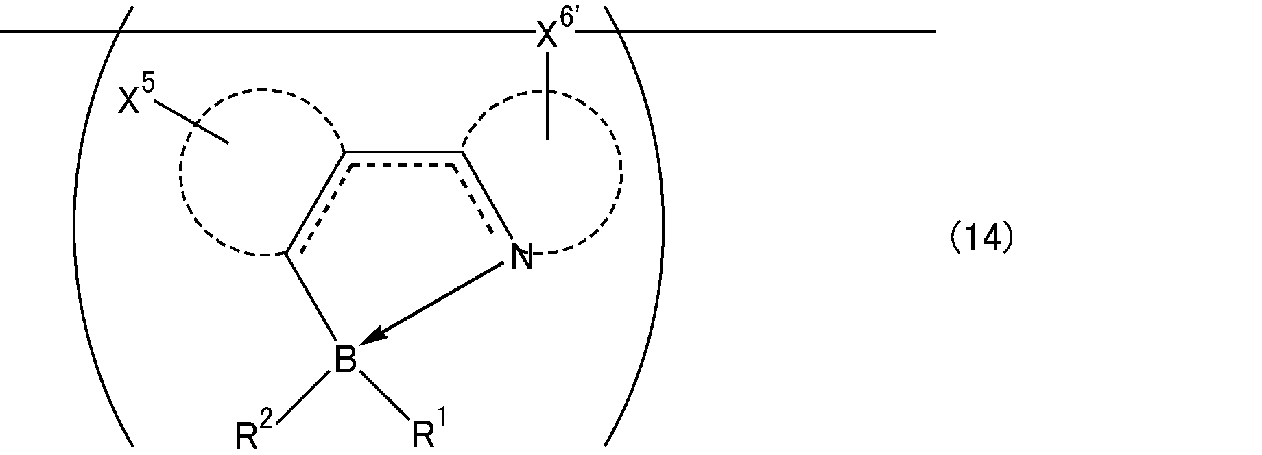
上記単独で重合し得る反応性基としては、3,5-ジブロモフェニル基、アルケニル基、アルキニル基、エポキシ基、ハロゲン原子等が挙げられる。上記式(2)のホウ素含有化合物がこれらの基のいずれかを少なくとも1つ有することで、上記式(2)のホウ素含有化合物は単独で重合することができる。これらの中でも、アルケニル基、エポキシ基、3,5-ジブロモフェニル基が好ましい。
上記式(2)中のX5、X6、R1及びR2の中で、重縮合する基は、上記重縮合し得る反応性基を構造中に有する置換基であればよい。同様に、単独重合する基は、上記単独で重合し得る反応性基を構造中に有する置換基であればよい。このような置換基としては、炭素数1~4の直鎖状又は分岐状アルキル基、炭素数3~7の環状アルキル基、炭素数1~8の直鎖状又は分岐状アルコキシ基、アリール基や複素環基等のいずれかの基の水素原子が上記重縮合し得る反応性基や単独で重合し得る反応性基で置換された基が挙げられる。これらの中でも、スチリル基、3,5-ジブロモフェニル基が好ましい。
本発明のホウ素含有重合体は、上記式(2)で表されるホウ素含有化合物を含む単量体成分から得られるものである限り、単量体成分にその他の単量体が含まれていてもよい。
すなわち、式(2)で表されるホウ素含有化合物と、下記式(15);
すなわち、式(2)で表されるホウ素含有化合物と、下記式(15);
(式中、Aは、2価の基を表す。X7及びX8は、同一若しくは異なって、水素原子又は1価の置換基を表し、X7及びX8の少なくとも1つの基は、反応性基を有する置換基である。)で表されるその他の単量体とを重合して形成されるホウ素含有重合体もまた、本発明におけるホウ素含有重合体に含まれる。
上記式(15)におけるAは、2価の基であれば、特に制限されないが、その構造を相当する化合物名として挙げると例えば、ベンゼン、ナフタレン、アントラセン、フェナントレン、クリセン、ルブレン、ピレン、ペリレン、インデン、アズレン、アダマンタン、フルオレン、フルオレノン、ジベンゾフラン、カルバゾール、ジベンゾチオフェン、フラン、ピロール、ピロリン、ピロリジン、チオフェン、ジオキソラン、ピラゾール、ピラゾリン、ピラゾリジン、イミダゾール、オキサゾール、チアゾール、オキサジアゾール、トリアゾール、チアジアゾール、ピラン、ピリジン、ピペリジン、ジオキサン、モルホリン、ピリダジン、ピリミジン、ピラジン、ピペラジン、トリアジン、トリチアン、ノルボルネン、ベンゾフラン、インドール、ベンゾチオフェン、ベンズイミダゾール、ベンゾオキサゾール、ベンゾチアゾール、ベンゾチアジアゾール、ベンゾオキサジアゾール、プリン、キノリン、イソキノリン、クマリン、シノリン、キノキサリン、アクリジン、フェナントロリン、フェノチアジン、フラボン、トリフェニルアミン、アセチルアセトン、ジベンゾイルメタン、ピコリン酸、シロール、ポルフィリン、イリジウム等の金属配位化合物、又は、それらが置換基を有している誘導体、それら誘導体の構造を含むポリマー若しくはオリゴマー等が挙げられる。
なお、上記置換基としては、上記R1及びR2における置換基と同様のものを用いることができる。
なお、上記置換基としては、上記R1及びR2における置換基と同様のものを用いることができる。
上記Aとしては、上述したものに加えて、例えば、下記式(16-1)~(16-4)の構造が挙げられる。

(式中、Ar1、Ar2、Ar3は、同一若しくは異なって、アリーレン基、2価の複素環基又は金属錯体構造を有する2価の基を表す。Z1は、-C≡C-、-N(Q3)-、-(SiQ4Q5)b-、又は、直接結合を示す。Z2は、-CQ1=CQ2-、-C≡C-、-N(Q3)-、-(SiQ4Q5)b-、又は、直接結合を表す。Q1及びQ2は、同一若しくは異なって、水素原子、アルキル基、アリール基、1価の複素環基、カルボキシル基、アルキルオキシカルボニル基、アリールオキシカルボニル基、アリールアルキルオキシカルボニル基、ヘテロアリールオキシカルボニル基、又は、シアノ基を表す。Q3、Q4及びQ5は、同一若しくは異なって、水素原子、アルキル基、アリール基、1価の複素環基、又は、アリールアルキル基を示す。aは0~1の整数を表す。bは1~12の整数を表す。)
上記アリーレン基とは、芳香族炭化水素から、水素原子2個を除いた原子団であり、環を構成する炭素数は通常6~60程度であり、好ましくは6~20である。該芳香族炭化水素としては、縮合環をもつもの、独立したベンゼン環または縮合環2個以上が直接又はビニレン等の基を介して結合したものも含まれる。
上記アリーレン基としては、例えば、下記式(17-1)~(17-23)で表される基等が挙げられる。これらの中でもフェニレン基、ビフェニレン基、フルオレン-ジイル基、スチルベン-ジイル基が好ましい。
なお、式(17-1)~(17-23)において、Rは、同一若しくは異なって、水素原子、ハロゲン原子、アルキル基、アルキルオキシ基、アルキルチオ基、アリール基、アリールオキシ基、アリールチオ基、アリールアルキル基、アリールアルキルオキシ基、アリールアルキルチオ基、アシル基、アシルオキシ基、アミド基、イミド基、イミン残基、アミノ基、置換アミノ基、置換シリル基、置換シリルオキシ基、置換シリルチオ基、置換シリルアミノ基、1価の複素環基、ヘテロアリールオキシ基、ヘテロアリールチオ基、アリールアルケニル基、アリールエチニル基、カルボキシル基、アルキルオキシカルボニル基、アリールオキシカルボニル基、アリールアルキルオキシカルボニル基、ヘテロアリールオキシカルボニル基またはシアノ基を表す。式(17-1)中においてx-yで示した線のように、環構造に交差して付された線は、環構造が被結合部分における原子と直接結合していることを意味する。すなわち、式(17-1)においては、x-yで示される線が付された環を構成する炭素原子のいずれかと直接結合することを意味し、その環構造における結合位置は限定されない。式(17-10)中においてz-で示した線のように、環構造の頂点に付された線は、その位置において環構造が被結合部分における原子と直接結合していることを意味する。また、環構造に交差して付されたRの付いた線は、Rが、その環構造に対して1つ結合していてもよく、複数結合していてもよいことを意味し、その結合位置も限定されない。
また、式(17-1)~(17-10)及び(17-15)~(17-20)において、炭素原子は、窒素原子、酸素原子又は硫黄原子と置き換えられていてもよく、水素原子はフッ素原子に置換されていてもよい。


上記2価の複素環基とは、複素環化合物から水素原子2個を除いた残りの原子団をいい、環を構成する炭素数は通常3~60程度である。該複素環化合物としては、環式構造をもつ有機化合物のうち、環を構成する元素が炭素原子だけでなく、酸素、硫黄、窒素、リン、ホウ素、ヒ素などのヘテロ原子を環内に含むものも含まれる。
上記2価の複素環基としては、例えば、下記式(18-1)~(18-38)で表される複素環基等が挙げられる。
なお、式(18-1)~(18-38)において、Rは、上記アリーレン基の有するRと同様である。Yは、O、S、SO、SO2、Se、又は、Teを表す。環構造に交差して付された線、環構造の頂点に付された線、環構造に交差して付されたRの付いた線については、式(17-1)~(17-23)と同様である。
また、式(18-1)~(18-38)において、炭素原子は、窒素原子、酸素原子又は硫黄原子と置き換えられていてもよく、水素原子はフッ素原子に置換されていてもよい。
なお、式(18-1)~(18-38)において、Rは、上記アリーレン基の有するRと同様である。Yは、O、S、SO、SO2、Se、又は、Teを表す。環構造に交差して付された線、環構造の頂点に付された線、環構造に交差して付されたRの付いた線については、式(17-1)~(17-23)と同様である。
また、式(18-1)~(18-38)において、炭素原子は、窒素原子、酸素原子又は硫黄原子と置き換えられていてもよく、水素原子はフッ素原子に置換されていてもよい。


上記金属錯体構造を有する2価の基とは、有機配位子を有する金属錯体の有機配位子から水素原子を2個除いた残りの2価の基である。該有機配位子の炭素数は、通常4~60程度であり、例えば、8-キノリノール及びその誘導体、ベンゾキノリノール及びその誘導体、2-フェニル-ピリジン及びその誘導体、2-フェニル-ベンゾチアゾール及びその誘導体、2-フェニル-ベンゾキサゾール及びその誘導体、ポルフィリン及びその誘導体等が挙げられる。
上記金属錯体の中心金属としては、例えば、アルミニウム、亜鉛、ベリリウム、イリジウム、白金、金、ユーロピウム、テルビウムなどが挙げられ、上記有機配位子を有する金属錯体としては、低分子の蛍光材料、燐光材料として公知の金属錯体、三重項発光錯体などが挙げられる。
上記金属錯体構造を有する2価の基としては、具体的には、例えば下記式(19-1)~(19-7)で表される基が挙げられる。
なお、式(19-1)~(19-7)において、Rは、上記アリーレン基の有するRと同様である。環構造の頂点に付された線については、式(17-1)~(17-23)と同様、直接結合を意味する。
また、式(19-1)~(19-7)において、炭素原子は、窒素原子、酸素原子又は硫黄原子と置き換えられていてもよく、水素原子はフッ素原子に置換されていてもよい。
なお、式(19-1)~(19-7)において、Rは、上記アリーレン基の有するRと同様である。環構造の頂点に付された線については、式(17-1)~(17-23)と同様、直接結合を意味する。
また、式(19-1)~(19-7)において、炭素原子は、窒素原子、酸素原子又は硫黄原子と置き換えられていてもよく、水素原子はフッ素原子に置換されていてもよい。


また、Aの構造としては、下記式(16-5)のような構造も挙げられる。

(式中、Ar4、Ar5、Ar6及びAr7は、同一又は異なって、アリーレン基又は2価の複素環基を表す。Ar8、Ar9及びAr10は、同一又は異なって、アリール基又は1価の複素環基を表す。o及びpは、同一又は異なって、0又は1を表し、0≦o+p≦1である。)
上記式(16-5)で表される構造の具体例としては、下記式(20-1)~(20-8)で表される構造が挙げられる。


なお、式(20-1)~(20-8)において、Rは、上記アリーレン基の有するRと同様である。環構造の頂点に付された線については、式(17-1)~(17-23)と同様、直接結合を意味する。上記式(20-1)~(20-8)において、1つの構造式中に複数のRを有しているが、それらは同一であってもよいし、異なる基であってもよい。溶媒への溶解性を高めるためには、水素原子以外を1つ以上有していることが好ましく、また置換基を含めた構造の形状の対称性が少ないことが好ましい。更に、上記式(20-1)~(20-8)において、Rがアリール基や複素環基をその一部に含む場合は、それらが更に1つ以上の置換基を有していてもよい。また、Rがアルキル鎖を含む置換基においては、それらは直鎖、分岐若しくは環状のいずれか又はそれらの組み合わせであってもよく、直鎖でない場合としては、例えば、イソアミル基、2-エチルヘキシル基、3,7-ジメチルオクチル基、シクロヘキシル基、4-C1~C12アルキルシクロヘキシル基等が挙げられる。本発明のホウ素含有共重合体の溶媒への溶解性を高めるためには、1つ以上に環状または分岐のあるアルキル鎖が含まれることが好ましい。
また、複数のRが連結して環を形成していてもよい。更に、Rがアルキル鎖を含む基の場合は、該アルキル鎖は、ヘテロ原子を含む基で中断されていてもよい。該ヘテロ原子としては、酸素原子、硫黄原子、窒素原子等が挙げられる。
また、複数のRが連結して環を形成していてもよい。更に、Rがアルキル鎖を含む基の場合は、該アルキル鎖は、ヘテロ原子を含む基で中断されていてもよい。該ヘテロ原子としては、酸素原子、硫黄原子、窒素原子等が挙げられる。
上記Aの構造としては、上述したものの中でも、式(16-5)、式(17-9)式(18-16)、式(18-28)であることが好ましい。
上記ホウ素含有重合体は、式(2)中のX5、X6、R1及びR2の少なくとも1つの基と式(15)中のX7及びX8の少なくとも1つの基とが重合して形成される繰り返し単位を有するものである。すなわち、下記式(21);

(式中、点線の円弧、ホウ素原子と窒素原子とを繋ぐ骨格部分における点線部分、窒素原子からホウ素原子への矢印は、式(2)と同様である。X5´、X6´、R1´及びR2´は、式(12)と同様である。Aは、同一若しくは異なって、2価の基を表す。X7´及びX8´は、それぞれ式(15)のX7及びX8と同様の基、2価の基、3価の基、又は、直接結合を表す。)で表される繰り返し単位の構造を有するホウ素含有重合体もまた本発明におけるホウ素含有重合体に含まれる。
上記式(21)は、X5´、X6´、R1´及びR2´のうち、いずれか1つ以上、かつ、X7´及びX8´のうち、いずれか1つ以上が、重合体の主鎖の一部として結合を形成することを意味する。
上記式(21)で表される繰り返し単位を有するホウ素含有重合体において、上記式(2)由来の繰り返し単位、上記式(15)由来の繰り返し単位は、ランダム重合体であっても、ブロック重合体でも、グラフト重合体あってもよい。また、高分子主鎖に枝分かれがあり末端部が3つ以上ある場合やデンドリマーでも良い。また、上記式(2)で表されるホウ素含有化合物と上記式(15)で表される化合物とが重縮合して形成される重合体であってもよい。
また、上記式(21)で表される繰り返し単位を有するホウ素含有重合体は、上記式(2)由来の繰り返し単位、上記式(15)由来の繰り返し単位をそれぞれ1種含むものであってもよく、2種以上含むものであってもよい。繰り返し単位を2種以上含むものである場合、当該2種以上の構造は、ランダム重合体であっても、ブロック重合体でも、グラフト重合体あってもよい。また、高分子主鎖に枝分かれがあり末端部が3つ以上ある場合やデンドリマーでも良い。
上記式(21)で表されるホウ素含有重合体としては、(i)上記式(2)中のX5、X6、R1及びR2のうち、いずれか2つと、上記式(15)中のX7及びX8とが、重合体の主鎖の一部として結合を形成する場合、(ii)上記式(2)中のX5、X6、R1及びR2のうち、いずれか1つと、上記式(15)中のX7及びX8のいずれか1つの基とが、重合体の主鎖の一部として結合を形成する場合がある。これらの場合の繰り返し単位の構造の具体例として、例えば、下記式(22)、(23)のような構造がある。

(i)上記式(2)中のX5、X6、R1及びR2のうち、いずれか2つと、上記式(15)中のX7及びX8とが、重合体の主鎖の一部として結合を形成する場合、上記式(2)由来の繰り返し単位、上記式(15)由来の繰り返し単位がランダム付加したものであってもよく、ブロック付加したものであってもよく、上記式(2)中のX5、X6、R1及びR2のいずれかの基と上記式(15)中のX7及び/又はX8とが重縮合したものであってもよいが、これらの中でも、上記式(2)中のX5、X6、R1及びR2のいずれか2つの基と上記式(15)中のX7及び/又はX8とが重縮合した重合体の一例として上記式(2)中のX5、X6と上記式(15)中のX7及びX8とが重縮合したものは、下記式(24)で表される構造を繰り返し単位とする重合体となる。

上記(i)の構造の場合、上記式(21)で表される繰り返し単位のうち、上記式(2)由来の構造部分の具体例としては、上記式(13-1)~(13-6)のような構造がある。これらの中でも、(13-1)、(13-6)の構造であることが好ましい。より好ましくは、(13-1)の構造である。
上記式(2)中のX5、X6、R1及びR2のいずれかの基と、上記式(15)中のX7及びX8のいずれかの基とが重縮合する場合の反応性基の組み合わせとしては、上述したものと同様のものが挙げられる。すなわち、上記式(2)中のX5、X6、R1及びR2のいずれかの基と、上記式(15)中のX7及びX8のいずれかの基とが重縮合する場合、上記式(15)中のX7及びX8のうち、当該重縮合する基としては、上述した重縮合し得る反応性基を構造中に有する置換基のいずれかであることが好ましい。
また、上記式(15)中のX7及びX8のいずれかが、単独で重合し得る反応性基を構造中に有する置換基である場合、当該置換基は、上述した単独で重合し得る反応性基を構造中に有する置換基のいずれかであることが好ましい。
また、上記式(15)中のX7及びX8のいずれかが、単独で重合し得る反応性基を構造中に有する置換基である場合、当該置換基は、上述した単独で重合し得る反応性基を構造中に有する置換基のいずれかであることが好ましい。
本発明のホウ素含有重合体の両末端に結合している基は、特に制限されず、また、同一であっても良く、異なっていてもよい。上記両末端に結合している基としては、例えば、水素原子、ハロゲン原子、置換基を有していてもよいアリール基、オリゴアリール基、1価の複素環基、1価のオリゴ複素環基、アルキル基、アルコキシ基、アルキルチオ基、アリールオキシ基、アリールチオ基、アリールアルキル基、アリールアルコキシ基、アリールアルキルチオ基、アルケニル基、アルキニル基、アリル基、アミノ基、アゾ基、カルボキシル基、アシル基、アルコキシカルボニル基、ホルミル基、ニトロ基、シアノ基、シリル基、スタニル基、ボリル基、ホスフィノ基、シリルオキシ基、アリールスルホニルオキシ基、アルキルスルホニルオキシ基等が挙げられる。
本発明におけるホウ素含有重合体は、重量平均分子量が103~108であることが好ましい。重量平均分子量がこのような範囲であると、良好に薄膜化できる。より好ましくは、103~107であり、更に好ましくは104~106である。
上記重量平均分子量は、ポリスチレン換算によるゲルパーミエーションクロマトグラフィ(GPC装置、展開溶媒;クロロホルム)によって以下の装置、及び、測定条件で測定することができる。
高速GPC装置:HLC-8220GPC(東ソー社製)
展開溶媒 クロロホルム
カラム TSK-gel GMHXL ×2本
溶離液流量 1ml/min
カラム温度 40℃
上記重量平均分子量は、ポリスチレン換算によるゲルパーミエーションクロマトグラフィ(GPC装置、展開溶媒;クロロホルム)によって以下の装置、及び、測定条件で測定することができる。
高速GPC装置:HLC-8220GPC(東ソー社製)
展開溶媒 クロロホルム
カラム TSK-gel GMHXL ×2本
溶離液流量 1ml/min
カラム温度 40℃
本発明におけるホウ素含有重合体は、上記式(2)で表されるホウ素含有化合物を含む単量体成分を重合することにより製造される。該単量体成分は、上記式(2)で表されるホウ素含有化合物を含む限り、その他の単量体を含んでいてもよいが、単量体成分全体100質量%に対して、上記式(2)で表されるホウ素含有化合物を0.1~99.9質量%含んでいることが好ましい。より好ましくは、10~90質量%である。
また、重合反応の際には、単量体成分の固形分濃度は、0.01質量%~溶解する最大濃度の範囲で適宜設定することができるが、希薄すぎると反応の効率が悪く、濃すぎると反応の制御が難しくなる恐れがあることから、好ましくは、0.1~20質量%である。
また、重合反応の際には、単量体成分の固形分濃度は、0.01質量%~溶解する最大濃度の範囲で適宜設定することができるが、希薄すぎると反応の効率が悪く、濃すぎると反応の制御が難しくなる恐れがあることから、好ましくは、0.1~20質量%である。
上記その他の単量体としては、上記式(15)で表される構造を有するものであることが好ましい。なお、上記単量体成分は、上記式(2)で表されるホウ素含有化合物、式(15)で表される化合物とも、1種含んでいてもよく、2種以上含んでいてもよい。
上記その他の単量体としては、上記式(15)で表される構造を有する化合物を含む場合、単量体成分に含まれる上記式(2)で表されるホウ素含有化合物1モルに対して、上記式(15)で表される構造を有する化合物を0.3~3モルの割合で含むことが好ましい。より好ましくは、上記式(2)で表されるホウ素含有化合物1モルに対して、0.2~2モルの割合である。
上記式(15)で表される化合物において、X7及びX8は、上述したX5及びX6における反応性基を有する置換基と同様のものを用いることができる。
本発明におけるホウ素含有重合体が重縮合反応により形成される場合、ホウ素含有重合体の製造方法は特に制限されないが、例えば、特開2011-184430号公報に記載の製造方法により製造することができる。
上記式(1)で表されるホウ素含有化合物や、上記式(2)で表されるホウ素含有化合物を含む単量体成分を重合して得られるホウ素含有重合体は、いずれも塗布による均一な成膜が可能であり、低いHOMO、LUMO準位を持つため、本発明の第1の有機電界発光素子の材料として好適に用いることができるものである。
[本発明の第2の好適な形態の有機電界発光素子]
本発明の第2の好適な形態の有機電界発光素子(以下、本発明の第2の有機電界発光素子とも記載する)は、バッファ層が、還元剤を含むものである。
本発明の有機電界発光素子においては、後述するように、第1の電極が陰極、第2の電極が陽極であり、バッファ層は、バッファ層を形成する材料の選択により、電子輸送層としての機能を発揮し得る層である。
有機電界発光素子では、陽極からホールが、陰極から電子が供給され、これらが発光層で再結合して発光することになるが、陽極から供給されるホールの一部は第2の金属酸化物層、発光層、バッファ層、第1の金属酸化物層を通過して陰極にまで達し、これが有機電界発光素子の効率を低下させる一因であると考えられる。所定の厚みのバッファ層を設けることで、ホールが陰極まで達することを抑制できるため、素子の効率を高めることができる。しかし一方で、バッファ層の厚みを厚くすると、陰極から発光層への電子の移動が妨げられ、バッファ層の厚みの影響が比較的少ないエッジ部とエッジ部以外の部分とで発光層にまで達する電子の割合に差が生じ、エッジ部のみが発光する現象がおこる。これに対し、バッファ層に電子を供給する機能を有する還元剤を含ませると、発光層へ充分な電子が供給されて電子とホールとの再結合が有効に行われることになり、発光に必要な駆動電圧も低くなる。これにより、発光効率が飛躍的に優れた有機電界発光素子とすることができる。
本発明の第2の有機電界発光素子は、第1の電極と第2の電極との間に、第1の金属酸化物層、バッファ層、該バッファ層上に積層された発光層を含む低分子化合物層、及び、第2の金属酸化物層をこの順に有し、該バッファ層が、還元剤を含むものであることが好ましい。
本発明の第2の有機電界発光素子は、第1の電極と第2の電極との間に、第1の金属酸化物層、バッファ層、該バッファ層上に積層された発光層を含む低分子化合物層、及び、第2の金属酸化物層をこの順に有するものである限り、これら以外の他の層を有していてもよい。本発明における低分子化合物の意味は上述したとおりである。
本発明の第2の有機電界発光素子は、第1の電極と第2の電極との間に、第1の金属酸化物層、バッファ層、該バッファ層上に積層された発光層を含む低分子化合物層、及び、第2の金属酸化物層をこの順に有するものである限り、これら以外の他の層を有していてもよい。本発明における低分子化合物の意味は上述したとおりである。
本発明の第2の有機電界発光素子において、バッファ層は、有機化合物を含む溶液を塗布することで形成される平均厚さが5~100nmの層であることが好ましい。
本発明の第2の有機電界発光素子において、第1の金属酸化物層の上に発光層を含む低分子化合物層を積層させる構成とした場合、金属酸化物層に接する低分子化合物層の結晶化が起こることによってリーク電流が増大して電流効率が低下し、顕著な場合では結晶化により均一な面発光が得られないという不具合が発生するおそれがある。有機無機ハイブリッド型の有機電界発光素子において、低分子化合物層が結晶化する原因は上述したとおりである。
このような結晶化は、有機無機ハイブリッド型の有機電界発光素子に特有の課題であり、発光層のホストとして低分子化合物を用いる場合に新たに生じる課題である。
この課題に対し、第1の金属酸化物層と発光層を含む低分子化合物層との間に有機化合物を含む溶液を塗布することで形成される平均厚さが5~100nmのバッファ層を設けると、低分子化合物層における低分子化合物の結晶化が抑制され、これによって、有機無機ハイブリッド型の有機電界発光素子が発光層等として低分子化合物から形成される層を有する場合でもリーク電流を抑制することができ、また、リーク電流を原因とする不均一な面発光は抑制することができる。
上述したように、バッファ層の厚みを厚くすると、発光層のエッジ部分のみが他の部分に比べて強く発光する現象が観察されるようになるが、これに対しては、バッファ層に還元剤を含ませることで、このようなエッジ部のみの発光を抑制し、均一な面発光を得ることができるようになる。したがって、本発明を用いれば、バッファ層の平均厚さが5~100nmであっても良好な素子特性が得られる。
本発明の第2の有機電界発光素子は、このように、電子輸送層として機能しうるバッファ層を塗布により形成し、そのバッファ層にn-ドーパントである還元剤を含ませたものであり、このような構成とすることで、発光層を低分子化合物で形成することも可能となり、また発光効率にも優れたものとなる。
バッファ層の形成方法や材料、好ましい厚み等については、後述する。
上記バッファ層が含む還元剤は、電子供与性の化合物であれば特に制限されないが、ヒドリド還元を行うことができるヒドリド還元剤であることが好ましい。
ヒドリド還元剤としては、2,3-ジヒドロベンゾ[d]イミダゾール化合物;2,3-ジヒドロベンゾ[d]チアゾール化合物;2,3-ジヒドロベンゾ[d]オキサゾール化合物;トリフェニルメタン化合物;ジヒドロピリジン化合物等の1種又は2種以上を用いることができる。
このように、ヒドリド還元剤が、2,3-ジヒドロベンゾ[d]イミダゾール化合物、2,3-ジヒドロベンゾ[d]チアゾール化合物、2,3-ジヒドロベンゾ[d]オキサゾール化合物、トリフェニルメタン化合物、及び、ジヒドロピリジン化合物からなる群より選択される少なくとも1種の化合物であることは本発明の好適な実施形態の1つである。
ヒドリド還元剤としては、この中でも、2,3-ジヒドロベンゾ[d]イミダゾール化合物や、ジヒドロピリジン化合物が好ましい。より好ましくは、(4-(1,3-ジメチル-2,3-ジヒドロ-1H-ベンゾイミダゾール-2-イル)フェニル)ジメチルアミン(N-DMBI)、または2,6-ジメチル-1,4-ジヒドロピリジン-3,5-ジカルボン酸ジエチル(ハンチュエステル)である。
上記バッファ層が含む還元剤の量は、バッファ層を形成する有機化合物100質量%に対して、0.1~15質量%であることが好ましい。還元剤をこのような割合で含むと、有機電界発光素子の発光効率を充分に高いものとすることができる。より好ましくは、バッファ層を形成する有機化合物100質量%に対して、0.5~10質量%であり、更に好ましくは、1~5質量%である。
本発明の第2の有機電界発光素子は、バッファ層上に積層された発光層を含む低分子化合物層を含むが、発光層を含む低分子化合物層とは、低分子化合物によって形成される1つの層又は低分子化合物によって形成される複数の層が積層されたものであって、その中の1つの層が発光層であるものである。すなわち、発光層を含む低分子化合物層とは、低分子化合物によって形成される発光層、又は、低分子化合物によって形成される発光層と低分子化合物によって形成されるその他の層とが積層されたもの、のいずれかである。低分子化合物によって形成されるその他の層は、1層であってもよく2層以上であってもよい。また、発光層とその他の層の積層される順番は特に制限されない。
上記低分子化合物によって形成されるその他の層は、正孔輸送層又は電子輸送層であることが好ましい。すなわち、低分子化合物層が複数の層からなるものである場合、発光層以外のその他の層として、正孔輸送層及び/又は電子輸送層を有することが好ましい。このように、有機電界発光素子が、発光層とは異なる独立した層として正孔輸送層及び/又は電子輸送層を有することは、本発明の第2の有機電界発光素子の好適な実施形態の1つである。
本発明の第2の有機電界発光素子が正孔輸送層を独立した層として有する場合、発光層と第2の金属酸化物層との間に正孔輸送層を有することが好ましい。本発明の第2の有機電界発光素子が電子輸送層を独立した層として有する場合、バッファ層と発光層との間に電子輸送層を有することが好ましい。
本発明の第2の有機電界発光素子が独立した層として正孔輸送層や電子輸送層を有さない場合、本発明の第2の有機電界発光素子の必須の構成として有する層のいずれかが、これらの層の機能を兼ねることになる。
本発明の第2の有機電界発光素子が正孔輸送層を独立した層として有する場合、発光層と第2の金属酸化物層との間に正孔輸送層を有することが好ましい。本発明の第2の有機電界発光素子が電子輸送層を独立した層として有する場合、バッファ層と発光層との間に電子輸送層を有することが好ましい。
本発明の第2の有機電界発光素子が独立した層として正孔輸送層や電子輸送層を有さない場合、本発明の第2の有機電界発光素子の必須の構成として有する層のいずれかが、これらの層の機能を兼ねることになる。
本発明の第2の有機電界発光素子の好ましい形態の1つは、有機電界発光素子が、第1の電極、第1の金属酸化物層、バッファ層、発光層、正孔輸送層、第2の金属酸化物層、第2の電極のみからなり、これらの層のいずれかが電子輸送層の機能を兼ねる形態である。
また、有機電界発光素子が、第1の電極、第1の金属酸化物層、バッファ層、発光層、第2の金属酸化物層、第2の電極のみからなり、これらの層のいずれかが正孔輸送層及び電子輸送層の機能を兼ねる形態もまた、本発明の第2の有機電界発光素子の好ましい形態の1つである。
また、有機電界発光素子が、第1の電極、第1の金属酸化物層、バッファ層、発光層、第2の金属酸化物層、第2の電極のみからなり、これらの層のいずれかが正孔輸送層及び電子輸送層の機能を兼ねる形態もまた、本発明の第2の有機電界発光素子の好ましい形態の1つである。
本発明の第2の有機電界発光素子において、第1の電極は陰極であり、第2の電極は陽極である。第1の電極、第2の電極として使用可能な化合物、及び、その中で好ましいものは、上述した本発明の第1の有機電界発光素子と同様である。
また、第1の電極、第2の電極の平均厚さの好ましい値も上述した本発明の第1の有機電界発光素子と同様である。
また、第1の電極、第2の電極の平均厚さの好ましい値も上述した本発明の第1の有機電界発光素子と同様である。
上記第1の金属酸化物層は、電子注入層として機能し、第2の金属酸化物層は、正孔注入層として機能する層である。
第1の金属酸化物層、第2の金属酸化物層を形成する化合物の具体例、及び、その中で好ましいものは、上述した本発明の第1の有機電界発光素子と同様である。
第1の金属酸化物層、第2の金属酸化物層を形成する化合物の具体例、及び、その中で好ましいものは、上述した本発明の第1の有機電界発光素子と同様である。
上記第1の金属酸化物層の平均厚さは、特に限定されないが、1~1000nmであることが好ましい。より好ましくは、2~100nmである。
上記第2の金属酸化物層の平均厚さは、特に限定されないが、1~1000nmであることが好ましい。より好ましくは、5~50nmである。
第1の金属酸化物層の平均厚さは、触針式段差計、分光エリプソメトリーにより測定することができる。
第2の金属酸化物層の平均厚さは、水晶振動子膜厚計により成膜時に測定することができる。
上記第2の金属酸化物層の平均厚さは、特に限定されないが、1~1000nmであることが好ましい。より好ましくは、5~50nmである。
第1の金属酸化物層の平均厚さは、触針式段差計、分光エリプソメトリーにより測定することができる。
第2の金属酸化物層の平均厚さは、水晶振動子膜厚計により成膜時に測定することができる。
発光層の材料としては、発光層の材料として通常用いることができるいずれの低分子化合物も用いることができ、これらを混合して用いてもよい。
低分子系のものとしては、上述した本発明の第1の有機電界発光素子におけるものと同様のものを用いることができる。
低分子系のものとしては、上述した本発明の第1の有機電界発光素子におけるものと同様のものを用いることができる。
上記発光層は、ドーパントを含んでいてもよい。ドーパントとしては、上述した本発明の第1の有機電界発光素子におけるものと同様のものを用いることができ、発光層がドーパントを含む場合のドーパントの含有量の好ましい範囲も上述した本発明の第1の有機電界発光素子の場合と同様である。
本発明の第2の有機電界発光素子の発光層は、上記のものの中でも、リン光発光材料を含むものであることが好ましい。発光層がリン光発光材料を含むことで、有機電界発光素子がより発光効率に優れたものとなる。
発光層がリン光発光材料を含む場合、ホスト材料にゲスト材料(ドーパント)としてリン光発光材料を含ませた材料により発光層が形成されることが好ましい。発光層がこのような材料で形成されるものである場合、発光層を形成する材料に対するリン光発光材料の含有量は、上記発光層がドーパントを含む場合の発光層を形成する材料に対するドーパントの含有量と同様であることが好ましい。
発光層がリン光発光材料を含む場合、ホスト材料にゲスト材料(ドーパント)としてリン光発光材料を含ませた材料により発光層が形成されることが好ましい。発光層がこのような材料で形成されるものである場合、発光層を形成する材料に対するリン光発光材料の含有量は、上記発光層がドーパントを含む場合の発光層を形成する材料に対するドーパントの含有量と同様であることが好ましい。
上記リン光発光材料としては、リン光発光材料としては、下記式(25)、(26)のいずれかで表される化合物を好適に用いることができる。

(式(25)中、点線の円弧は、酸素原子と3つの炭素原子とで構成された骨格部分の一部とともに環構造が形成されていることを表し、窒素原子を含んで形成される環構造は、複素環構造である。X’、X’’は、同一又は異なって、水素原子、又は、環構造の置換基となる1価の置換基を表し、点線の円弧部分を形成する環構造に複数個結合していてもよい。X’、X’’は、結合して点線の円弧で表される2つの環構造の一部とともに新たな環構造を形成してもよい。また、n2が2以上である場合には、複数のX’同士又はX’’同士が結合して1つの置換基を形成していてもよい。窒素原子と3つの炭素原子とで構成された骨格部分における点線は、点線で結ばれる2つの原子が単結合又は二重結合で結合していることを表す。M’は、金属原子を表す。窒素原子からM’への矢印は、窒素原子がM’原子へ配位していることを表す。n2は、金属原子M’の価数を表す。)

(式(26)中、点線の円弧は、酸素原子と3つの炭素原子とで構成された骨格部分の一部とともに環構造が形成されていることを表し、窒素原子を含んで形成される環構造は、複素環構造である。X’、X’’は、同一又は異なって、水素原子、又は、環構造の置換基となる1価の置換基を表し、点線の円弧部分を形成する環構造に複数個結合していてもよい。X’、X’’は、結合して点線の円弧で表される2つの環構造の一部とともに新たな環構造を形成してもよい。窒素原子と3つの炭素原子とで構成された骨格部分における点線は、点線で結ばれる2つの原子が単結合又は二重結合で結合していることを表す。M’は、金属原子を表す。窒素原子からM’への矢印は、窒素原子がM’原子へ配位していることを表す。n2は、金属原子M’の価数を表す。XaとXbとを結ぶ実線の円弧は、XaとXbとが少なくとも1つの他の原子を介して結合していることを表し、XaとXbとともに環構造を形成していてもよい。Xa、Xbは、同一又は異なって、酸素原子、窒素原子、炭素原子のいずれかを表す。XbからM’への矢印は、XbがM’原子へ配位していることを表す。m’は、1~3の数である。)
上記式(25)及び式(26)における点線の円弧で表される環構造としては、炭素数2~20の芳香環や複素環が挙げられ、ベンゼン環、ナフタレン環、アントラセン環等の芳香族炭化水素環;ピリジン環、ピリミジン環、ピラジン環、トリアジン環、ベンゾチアゾール環、ベンゾチオール環、ベンゾオキサゾール環、ベンゾオキソール環、ベンゾイミダゾール環、キノリン環、イソキノリン環、キノキサリン環、およびフェナントリジン環、チオフェン環、フラン環、ベンゾチオフェン環、ベンゾフラン環等の複素環が挙げられる。
上記式(25)及び式(26)においてX’、X’’で表される環構造が有する置換基としては、ハロゲン原子、炭素数1~20、好ましくは炭素数1~10のアルキル基、炭素数1~20、好ましくは炭素数1~10のアラルキル基、炭素数1~20、好ましくは炭素数1~10のアルケニル基、炭素数1~20、好ましくは炭素数1~10のアリール基、アリールアミノ基、シアノ基、アミノ基、アシル基、炭素数1~20、好ましくは炭素数1~10のアルコキシカルボニル基、カルボキシル基、炭素数1~20、好ましくは炭素数1~10のアルコキシ基、炭素数1~20、好ましくは炭素数1~10のアルキルアミノ基、炭素数1~20、好ましくは炭素数1~10のジアルキルアミノ基、炭素数1~20、好ましくは炭素数1~10のアラルキルアミノ基、炭素数1~20、好ましくは炭素数1~10のハロアルキル基、水酸基、アリールオキシ基、カルバゾール基等が挙げられる。
なお、X’、X’’で表される環構造が有する置換基がアリール基、アリールアミノ基である場合、アリール基、アリールアミノ基に含まれる芳香環が更に置換基を有していてもよく、その場合の置換基としては、上記X’、X’’で表される置換基の具体例と同じものが挙げられる。
なお、X’、X’’で表される環構造が有する置換基がアリール基、アリールアミノ基である場合、アリール基、アリールアミノ基に含まれる芳香環が更に置換基を有していてもよく、その場合の置換基としては、上記X’、X’’で表される置換基の具体例と同じものが挙げられる。
上記式(25)及び式(26)において、X’、X’’で表される置換基同士が結合して点線の円弧で表される2つの環構造の一部とともに新たな環構造を形成している場合、点線の円弧で表される2つの環構造と新たな環構造を合わせた環構造としては、例えば、下記(27-1)、(27-2)のような構造が挙げられる。

上記式(25)及び式(26)において、M’で表される金属原子としては、ルテニウム、ロジウム、パラジウム、銀、レニウム、オスミウム、イリジウム、白金及び金が挙げられる。
上記式(26)で表される構造としては、下記式(28-1)、(28-2)の構造等が挙げられる。

(式(28-1)、(28-2)中、R3~R5は、同一又は異なって、水素原子又は1価の置換基を表す。式(28-2)において、R3~R5が1価の置換基の場合、環構造が複数の1価の置換基を有していてもよい。窒素原子からM’への矢印及び酸素原子からM’への矢印は、窒素原子、酸素原子がM’原子へ配位していることを表す。点線の円弧、窒素原子と3つの炭素原子とで構成された骨格部分における点線、X’、X’’、M’、n2、m’は、式(26)と同様である。)
R3~R5の1価の置換基としては、上記式(25)、(26)においてX’、X’’で表される環構造が有する置換基と同様のものが挙げられる。
R3~R5の1価の置換基としては、上記式(25)、(26)においてX’、X’’で表される環構造が有する置換基と同様のものが挙げられる。
上記式(25)や式(26)で表される化合物の具体例としては、下記式(29-1)~(29-30)で表される化合物等が挙げられる。


本発明におけるリン光発光材料としては、上述のものの1種又は2種以上を用いることができるが、これらの中でも、上記式(29-1)で表されるイリジウム トリス(2-フェニルピリジン)(Ir(ppy)3)、上記式(29-19)で表されるイリジウム トリス(1-フェニルイソキノリン)(Ir(piq)3)、上記式(29-27)で表されるイリジウム ビス(2-メチルジベンゾ-[f,h]キノキサリン)(アセチルアセトナート)(Ir(MDQ)2(acac))、上記式(29-28)で表されるイリジウム トリス[3-メチル-2-フェニルピリジン](Ir(mpy)3)等が好ましい。
上記ホスト材料としては、下記式(30);

(式(30)中、点線の円弧は、酸素原子と窒素原子とを繋ぐ骨格部分の一部とともに環構造が形成されていることを表し、Z1と窒素原子とを含んで形成される環構造は、複素環構造である。X’、X’’は、同一又は異なって、水素原子、又は、環構造の置換基となる1価の置換基を表し、点線の円弧部分を形成する環構造に複数個結合していてもよい。X’、X’’は、結合して点線の円弧で表される2つの環構造の一部とともに新たな環構造を形成してもよい。酸素原子と窒素原子とを繋ぐ骨格部分における点線は、点線で結ばれる2つの原子が単結合又は二重結合で結合していることを表す。Mは、金属原子を表す。Z1は、炭素原子又は窒素原子を表す。窒素原子からMへの矢印は、窒素原子がM原子へ配位していることを表す。R0は、1価の置換基又は2価の連結基を表す。mはR0の数を表し、0又は1の数である。n3は、金属原子Mの価数を表す。rは、1又は2の数である。)で表される金属錯体、
下記式(31);
下記式(31);

(式中、X’、X’’は、同一又は異なって、水素原子、又は、キノリン環構造の置換基となる1価の置換基を表し、キノリン環構造に複数個結合していてもよい。Mは、金属原子を表す。窒素原子からMへの矢印は、窒素原子がM原子へ配位していることを表す。R0は、1価の置換基又は2価の連結基を表す。mはR0の数を表し、0又は1の数である。n3は、金属原子Mの価数を表す。rは、1又は2の数である。)で表される金属錯体、
下記式(32);
下記式(32);

(式中、点線の円弧は、酸素原子と窒素原子とを繋ぐ骨格部分の一部とともに環構造が形成されていることを表し、Z1と窒素原子とを含んで形成される環構造は、複素環構造である。X’、X’’は、同一又は異なって、水素原子、又は、環構造の置換基となる1価の置換基を表し、点線の円弧部分を形成する環構造に複数個結合していてもよい。X’、X’’は、結合して点線の円弧で表される2つの環構造の一部とともに新たな環構造を形成してもよい。酸素原子と窒素原子とを繋ぐ骨格部分における点線は、点線で結ばれる2つの原子が単結合又は二重結合で結合していることを表す。Mは、金属原子を表す。Z1は、炭素原子又は窒素原子を表す。窒素原子からMへの矢印は、窒素原子がM原子へ配位していることを表す。n3は、金属原子Mの価数を表す。XaとXbとを結ぶ実線の円弧は、XaとXbとが少なくとも1つの他の原子を介して結合していることを表し、XaとXbとともに環構造を形成していてもよい。また少なくとも1つの他の原子を介したXaとXbとの結合の中に配位結合を含んでいてもよい。Xa、Xbは、同一又は異なって、酸素原子、窒素原子、炭素原子のいずれかを表す。XbからMへの矢印は、XbがM原子へ配位していることを表す。m’は、1~3の数である。)で表される金属錯体が挙げられ、これらの1種又は2種以上を用いることができる。
上記式(30)において、rが1である場合、M原子を構造中に1つ有する下記式(33-1)で表される金属錯体となり、rが2である場合、M原子を構造中に2つ有する下記式(33-2)で表される金属錯体となる。

上記式(30)、式(32)において点線の円弧で表される環構造としては、1つの環からなる環構造であってもよく、2つ以上の環からなる環構造であってもよい。このような環構造としては、炭素数2~20の芳香環や複素環が挙げられ、ベンゼン環、ナフタレン環、アントラセン環等の芳香環;ジアゾール環、チアゾール環、イソチアゾール環、オキサゾール環、イソオキサゾール環、チアジアゾール環、オキサジアゾール環、トリアゾール環、イミダゾール環、イミダゾリン環、ピリジン環、ピラジン環、ピリダジン環、ピリミジン環、ジアジン環、トリアジン環、ベンゾイミダゾール環、ベンゾチアゾール環、ベンゾオキサゾール環、ベンゾトリアゾール環等の複素環が挙げられる。
これらの中でも、ベンゼン環、チアゾール環、イソチアゾール環、オキサゾール環、イソオキサゾール環、チアジアゾール環、オキサジアゾール環、トリアゾール環、イミダゾール環、イミダゾリン環、ピリジン環、ピリダジン環、ピリミジン環、ベンゾイミダゾール環、ベンゾチアゾール環、ベンゾオキサゾール環、ベンゾトリアゾール環が好ましい。
これらの中でも、ベンゼン環、チアゾール環、イソチアゾール環、オキサゾール環、イソオキサゾール環、チアジアゾール環、オキサジアゾール環、トリアゾール環、イミダゾール環、イミダゾリン環、ピリジン環、ピリダジン環、ピリミジン環、ベンゾイミダゾール環、ベンゾチアゾール環、ベンゾオキサゾール環、ベンゾトリアゾール環が好ましい。
上記式(30)~(32)においてX’、X’’で表される環構造が有する置換基としては、上記式(25)、式(26)においてX’、X’’で表される環構造が有する置換基と同様のものが挙げられる。
上記式(30)、式(32)において、X’、X’’で表される環構造が有する置換基同士が結合して点線の円弧で表される2つの環構造の一部とともに新たな環構造を形成している場合、点線の円弧で表される2つの環構造と新たな環構造を合わせた環構造としては、例えば、上記(27-1)、(27-2)のような構造が挙げられる。
上記式(30)、式(32)において、X’、X’’で表される環構造が有する置換基同士が結合して点線の円弧で表される2つの環構造の一部とともに新たな環構造を形成している場合、点線の円弧で表される2つの環構造と新たな環構造を合わせた環構造としては、例えば、上記(27-1)、(27-2)のような構造が挙げられる。
上記式(30)~(32)において、Mで表される金属原子としては、周期表の第1~3族、9族、10族、12族又は13族の金属原子が好ましく、亜鉛、アルミニウム、ガリウム、白金、ロジウム、イリジウム、ベリリウム、マグネシウムのいずれかが好ましい。
上記式(30)、式(31)においてR0が1価の置換基である場合、1価の置換基は、下記式(34-1)~(34-3)のいずれかであることが好ましい。

(式中、Ar1~Ar5は、置換基を有していてもよい芳香環、複素環、若しくは、芳香環又は複素環が2つ以上直接に結合した構造を表し、Ar3~Ar5は、同一の構造であっても異なる構造であっていてもよい。Q0は、ケイ素原子又はゲルマニウム原子を表す。)
Ar1~Ar5の芳香環又は複素環の具体例としては、上記式(30)において点線の円弧で表される環構造の芳香環又は複素環の具体例と同様のものを挙げることができ、芳香環又は複素環が2つ以上直接に結合した構造としては、これら芳香環又は複素環の具体例として挙げられた環構造が2つ以上直接に結合した構造が挙げられる。なおこの場合、直接に結合する2つ以上の芳香環や複素環は同一の環構造であってもよく、異なる環構造であってもよい。
芳香環又は複素環の置換基の具体例としては、上記式(30)において点線の円弧で表される環構造の芳香環又は複素環の置換基の具体例と同様のものを挙げることができる。
Ar1~Ar5の芳香環又は複素環の具体例としては、上記式(30)において点線の円弧で表される環構造の芳香環又は複素環の具体例と同様のものを挙げることができ、芳香環又は複素環が2つ以上直接に結合した構造としては、これら芳香環又は複素環の具体例として挙げられた環構造が2つ以上直接に結合した構造が挙げられる。なおこの場合、直接に結合する2つ以上の芳香環や複素環は同一の環構造であってもよく、異なる環構造であってもよい。
芳香環又は複素環の置換基の具体例としては、上記式(30)において点線の円弧で表される環構造の芳香環又は複素環の置換基の具体例と同様のものを挙げることができる。
上記式(30)、式(31)においてR0が2価の連結基である場合、R0は-O-、-CO-いずれかであることが好ましい。
上記式(32)において、Xa、Xbと、XaとXbとを結ぶ実線の円弧とで形成される構造は、環構造を1つ又は複数含んでいてもよい。環構造は、Xa、Xbを含んで形成されていてもよく、その場合の環構造としては、上記式(30)、式(32)において点線の円弧で表される環構造と同様のものや、ピラゾール環が挙げられる。好ましくは、Xa、Xbを含んでピラゾール環が形成された構造である。
上記式(32)において、XaとXbとを結ぶ実線の円弧は、炭素原子のみからなるものであってもよく、他の原子を含んでいてもよい。他の原子としては、ホウ素原子、窒素原子、硫黄原子等が挙げられる。
またXaとXbとを結ぶ実線の円弧は、Xa、Xbを含んで形成される環構造以外の環構造を1つ又は2つ以上含んでいてもよく、その場合の環構造としては、上記式(30)、式(32)において点線の円弧で表される環構造と同様のものや、ピラゾール環が挙げられる。
またXaとXbとを結ぶ実線の円弧は、Xa、Xbを含んで形成される環構造以外の環構造を1つ又は2つ以上含んでいてもよく、その場合の環構造としては、上記式(30)、式(32)において点線の円弧で表される環構造と同様のものや、ピラゾール環が挙げられる。
上記式(32)で表される構造としては、下記式(35)の構造等が挙げられる。

(式(35)中、R3~R5は、同一又は異なって、水素原子又は1価の置換基を表す。窒素原子からMへの矢印及び酸素原子からMへの矢印は、窒素原子、酸素原子がM原子へ配位していることを表す。点線の円弧、酸素原子と窒素原子とを繋ぐ骨格部分における点線、X’、X’’、M、Z1、n3、m’は、式(32)と同様である。)
式(35)のR3~R5の1価の置換基としては、上記式(25)、(26)においてX’、X’’で表される環構造が有する置換基と同様のものが挙げられる。
式(35)のR3~R5の1価の置換基としては、上記式(25)、(26)においてX’、X’’で表される環構造が有する置換基と同様のものが挙げられる。
上記式(30)で表される化合物の具体例としては、下記式(36-1)~(36-40)で表される構造の化合物等が挙げられる。


上記式(31)で表される化合物の具体例としては、下記式(37-1)~(37-3)で表される構造の化合物等が挙げられる。

上記式(32)で表される化合物の具体例としては、下記式(38-1)~(38-8)で表される構造の化合物等が挙げられる。

本発明におけるホスト材料としては、上述のものの1種又は2種以上を用いることができるが、これらの中でも、上記式(36-11)で表されるビス[2-(2-ベンゾチアゾリル)フェノラト]亜鉛、上記式(36-34)で表されるビス(10-ヒドロキシベンゾ[h]キノリナート)ベリリウム(Bebq2)、上記式(36-35)で表されるビス[2-(2-ヒドロキシフェニル)-ピリジン]ベリリウム(Bepp2)が好ましい。
上記発光層の平均厚さは、特に限定されないが、10~150nmであることが好ましい。より好ましくは、20~100nmである。
発光層の平均厚さは、水晶振動子膜厚計により成膜時に測定することができる。
発光層の平均厚さは、水晶振動子膜厚計により成膜時に測定することができる。
上記正孔輸送層の材料としては、上述した本発明の第1の有機電界発光素子における正孔輸送層の材料と同様のものを用いることができる。
また、正孔輸送層の平均厚さの好ましい値も上述した本発明の第1の有機電界発光素子の場合と同様である。
また、正孔輸送層の平均厚さの好ましい値も上述した本発明の第1の有機電界発光素子の場合と同様である。
上記電子輸送層の材料としては、上述した本発明の第1の有機電界発光素子における電子輸送層の材料と同様のものを用いることができる。
また、電子輸送層の平均厚さの好ましい値も上述した本発明の第1の有機電界発光素子の場合と同様である。
また、電子輸送層の平均厚さの好ましい値も上述した本発明の第1の有機電界発光素子の場合と同様である。
本発明の有機電界発光素子において、第1、第2の金属酸化物層、第2の電極、発光層、正孔輸送層、電子輸送層を形成する方法もまた、上述した本発明の第1の有機電界発光素子におけるこれらの層の形成方法と同様である。
本発明の有機電界発光素子が含むバッファ層は、上述のとおり、有機化合物を含む溶液を塗布することで形成される層であることが好ましい。塗布により所定の厚みのバッファ層を形成することでバッファ層上に成膜する低分子化合物の結晶化を効果的に抑制することが可能となる。
上記有機化合物を含む溶液を塗布する方法、有機化合物を含む溶液を調製するために使用する溶媒、及び、溶媒中の有機化合物の濃度もまた、上述した本発明の第1の有機電界発光素子において有機化合物を含む溶液を塗布してバッファ層を形成する場合の方法、及び、溶媒、及び、濃度と同様である。
バッファ層を塗布成膜することで、第1の金属酸化物層表面に存在する凹凸が平滑化されるため、次にバッファ層上に成膜する低分子化合物の結晶化が抑制される。
このようなバッファ層と特開2012-4492号公報(特許文献5)に開示されている発明との相違は、上述したとおりである。
上記有機化合物を含む溶液を塗布する方法、有機化合物を含む溶液を調製するために使用する溶媒、及び、溶媒中の有機化合物の濃度もまた、上述した本発明の第1の有機電界発光素子において有機化合物を含む溶液を塗布してバッファ層を形成する場合の方法、及び、溶媒、及び、濃度と同様である。
バッファ層を塗布成膜することで、第1の金属酸化物層表面に存在する凹凸が平滑化されるため、次にバッファ層上に成膜する低分子化合物の結晶化が抑制される。
このようなバッファ層と特開2012-4492号公報(特許文献5)に開示されている発明との相違は、上述したとおりである。
上記バッファ層は、平均厚さが5~100nmであることが好ましい。平均厚さがこのような範囲であることで、発光層を含む低分子化合物層の結晶化を抑制する効果を充分に発揮することができる。バッファ層の平均厚さが5nmより薄いと、第1の金属酸化物表面に存在する凹凸を十分に平滑化できず、リーク電流が大きくなってバッファ層を形成することの効果を充分に発揮することができないおそれがある。また、バッファ層の平均厚さが100nmより厚いと、駆動電圧が上昇し実用上好ましくない。また、有機化合物として、後述する本発明における好ましい構造の化合物を用いた場合には、バッファ層は電子輸送層としての機能も充分に発揮することができる。上記バッファ層の平均厚さは、より好ましくは、10~60nmである。
バッファ層の平均厚さは触針式段差計、分光エリプソメトリーにより測定することができる。
バッファ層の平均厚さは触針式段差計、分光エリプソメトリーにより測定することができる。
本発明の第2の有機電界発光素子は、基板上に有機電界発光素子を構成する各層が積層されたものであってもよい。基板上に各層が積層されたものである場合、基板上に形成された第1の電極上に、各層が形成されたものであることが好ましい。この場合、本発明の有機電界発光素子は、基板がある側とは反対側に光を取り出すトップエミッション型のものであってもよく、基板がある側に光を取り出すボトムエミッション型のものであってもよい。
上記基板の材料、基板の平均厚さは、上述した本発明の第1の有機電界発光素子における基板の材料、基板の平均厚さと同様である。
本発明の第2の有機電界発光素子において、バッファ層を形成する有機化合物の例としては、上述した本発明の第1の有機電界発光素子におけるバッファ層を形成する有機化合物と同様のものが挙げられる。
また、本発明の第2の有機電界発光素子において、バッファ層を形成する有機化合物は、ホウ素原子を有する有機化合物であることが好ましく、上述した式(1)で表されるホウ素含有化合物であることがより好ましい。このような構造のホウ素含有化合物が好ましい理由は、上述したとおりである。
また式(1)で表されるホウ素含有化合物の中での好ましい構造も、本発明の第1の有機電界発光素子の場合と同様である。
また、本発明の第2の有機電界発光素子において、バッファ層を形成する有機化合物は、ホウ素原子を有する有機化合物であることが好ましく、上述した式(1)で表されるホウ素含有化合物であることがより好ましい。このような構造のホウ素含有化合物が好ましい理由は、上述したとおりである。
また式(1)で表されるホウ素含有化合物の中での好ましい構造も、本発明の第1の有機電界発光素子の場合と同様である。
上記式(1)で表されるホウ素含有化合物は、塗布による均一な成膜が可能であり、低いHOMO、LUMO準位を持つため、本発明の第2の有機電界発光素子の材料として好適に用いることができるものである。
本発明の第2の有機電界発光素子は、本発明の有機電解発光素子であって、バッファ層が、還元剤を含むものであり、これにより、有機電解発光素子を発光特性に優れたものとすることが可能となる。このような本発明の第2の有機電界発光素子の中でも、第1の電極と第2の電極との間に、第1の金属酸化物層、バッファ層、該バッファ層上に積層された発光層を含む低分子化合物層、及び、第2の金属酸化物層をこの順に有し、該バッファ層が、還元剤を含むものが好ましい。
このような本発明の第2の好適な形態の有機無機ハイブリッド型の有機電界発光素子の製造方法、すなわち、複数の層を積層した構造を有する有機電界発光素子の製造方法であって、該製造方法は、有機電界発光素子が、第1の電極と第2の電極との間に、第1の金属酸化物層、還元剤を含むバッファ層、該バッファ層上に積層された発光層を含む低分子化合物層、及び、第2の金属酸化物層をこの順に有するものとなるように有機電界発光素子を構成する各層を積層する工程を含むことを特徴とする本発明の第2の好適な形態の有機電界発光素子の製造方法もまた、本発明の1つである。
本発明の第2の好適な形態の有機電界発光素子の製造方法は、有機化合物を含む溶液を塗布して平均厚さが5~100nmのバッファ層を形成する工程を含むことが好ましい。
上記本発明の第2の好適な形態の有機電界発光素子の製造方法は、上記工程を含むものである限り、その他の工程を含んでいてもよく、第1、第2の金属酸化物層、バッファ層、発光層を含む低分子化合物層以外の層を形成する工程を含んでいてもよい。また、有機電界発光素子の各層を形成する材料、形成方法、有機化合物、有機化合物を含む溶液を調製するために用いる溶媒、及び、各層の厚みは、本発明の第2の有機電界発光素子と同様であり、好ましいものも同様である。
[本発明の第3の好適な形態の有機電界発光素子]
本発明の第3の好適な形態の有機発光素子(以下、本発明の第3の有機電界発光素子とも記載する)は、本発明の有機発光素子において、バッファ層が窒素含有膜からなり、平均厚さが3~150nmの層であるものである。
本発明の第3の有機電界発光素子は、言い換えると、陽極と、基板上に形成された陰極との間に複数の層が積層された構造を有する有機電界発光素子であって、上記有機電界発光素子は、陽極と陰極との間に金属酸化物層を有し、上記金属酸化物層上に、窒素含有膜からなり、平均厚さが3~150nmの層を有するものである。
窒素含有膜は、電子輸送性を有さないものであることが好ましい。なお、ここでいう電子輸送性を有さないとは、電子移動度が極端に低いことを指す。具体的には電子移動度が10-6cm2/Vs程度より小さい、もしくは、電気伝導率が10-6S/m程度より小さい、のいずれかに該当することを指す。
本発明の第3の有機電界発光素子は、陽極と、基板上に形成された陰極との間に複数の層が積層された構造を有する逆構造の有機電界発光素子であって、陽極と陰極との間に金属酸化物層を有し、該金属酸化物層上に、窒素含有膜からなり、平均厚さが3~150nmの層を有するものである限り、他の層の数、他の層を構成する材料や積層する順番は特に制限されないが、金属酸化物層と窒素含有化合物層とが、陰極と発光層との間にあることが好ましい。窒素含有化合物は、電子注入特性に優れたものであり、このような層構成を有する有機電界発光素子は、高い電子注入特性を有することになり、発光効率に優れた素子となる。
本発明の第3の有機電界発光素子に用いられる窒素含有膜には、(1)金属酸化物層上で窒素含有化合物により形成された窒素含有膜、(2)金属酸化物層上で窒素含有化合物により形成された高窒素含有膜、(3)金属酸化物層上で窒素含有化合物を分解させることで形成された窒素含有膜、(4)金属酸化物層上で窒素含有化合物を分解させることで形成された高窒素含有膜の合計4種類が存在する。
このような膜を形成することで有機電界発光素子の性能が向上する理由については以下のように推定される。
まず第一に窒素原子を含む場合、その孤立電子対は基材中の金属原子と結合を作る傾向にある。その金属-窒素結合間の分極が、強い電子注入特性を発現することになる。上記(1)~(4)全ての窒素含有膜において、それは満たされる。より好適には、孤立電子対を有する窒素原子比率が高い上記(2)が適している。
上記(3)、(4)では、膜生成に関わる分解の現象により高密度に窒素原子が基材上に存在する膜となる事が期待され、結果として、多彩な金属-窒素結合が出現することが期待される。そしてその中には、従来よりも強固な金属-窒素結合も存在すると考えられる。さらに、分解の状況によっては、不要な炭素等の他の成分が消失する事により、相対的に窒素原子分率が上昇し、結果として、より好適な環境が実現される場合もある(4)。これらの窒素含有膜では、主たる窒素の起源が金属-窒素結合になることから、通常の分子の物理吸着よりも高密度に窒素原子が集積されていると期待される。これらの要因により、このような窒素含有膜を有することで、有機電界発光素子が、発光効率に優れ、素子駆動安定性と素子寿命に優れたものとなると考えられる。実際、上記窒素含有化合物の分解に起因する現象は、表面分析手法の一つであるX線光電子分光法により立証できる。具体的な結果は実施例で示すが、窒素含有化合物として窒素と炭素とを構成元素として含む化合物を用い、この化合物を分解させる処理をすることにより、炭素:窒素比(CN比)が2:1から1:1にまで高窒素比率になっている事が観測されている。また同時に、上記処理により、窒素のスペクトルの半値幅の増加が観測されており、この事は、化学環境の広がりを示しており、より強固な金属-窒素結合の出現も示唆されている。
したがって、窒素含有膜からなる層の下地が金属元素を含む膜であることも上記のような本発明の第3の有機電界発光素子が奏する効果の発現に大きく寄与していると考えられる。
上記(1)、(2)の窒素含有膜は、金属酸化物層上に形成された窒素含有化合物からなる膜、すなわち、窒素含有化合物が分解することなく膜を形成したものである。上記(2)の窒素含有膜は、窒素含有化合物として、窒素含有化合物を構成する全原子数に対する窒素原子数の割合が高いものを用いて形成されるものである。
上記(1)、(2)の窒素含有膜の形成方法は特に制限されないが、窒素含有化合物の溶液を金属酸化物層上に塗布した後、溶媒を揮発させる方法が好適に用いられる。
上記(1)、(2)の窒素含有膜の形成方法は特に制限されないが、窒素含有化合物の溶液を金属酸化物層上に塗布した後、溶媒を揮発させる方法が好適に用いられる。
上記(3)、(4)の窒素含有膜は、金属酸化物層上で窒素含有化合物を分解させることで形成される膜であるが、窒素含有化合物の一部に分解されないものが残っていてもよい。好ましくは、窒素含有化合物の全てが分解されることである。
上記(3)、(4)の窒素含有膜の形成方法は特に制限されないが、窒素含有化合物の溶液を金属酸化物層上に塗布した後、窒素含有化合物を分解して形成する方法が好適に用いられる。
上記(3)、(4)の窒素含有膜の形成方法は特に制限されないが、窒素含有化合物の溶液を金属酸化物層上に塗布した後、窒素含有化合物を分解して形成する方法が好適に用いられる。
上記窒素含有膜は、金属酸化物層上に窒素含有化合物を含む溶液を塗布する工程を含む方法により形成されたものであることが好ましい。このような工程を含む方法で窒素含有膜を形成することで、金属酸化物層を有する有機電界発光素子がリーク電流の抑制と、均一な面発光を得ることができることになる。
この理由は、上述した本発明の第1の有機発光素子において、有機化合物を含む溶液を塗布することで形成されるバッファ層を有することでリーク電流の抑制と、均一な面発光を得ることができる理由と同じである。
この理由は、上述した本発明の第1の有機発光素子において、有機化合物を含む溶液を塗布することで形成されるバッファ層を有することでリーク電流の抑制と、均一な面発光を得ることができる理由と同じである。
上記窒素含有膜は、膜を構成する元素として窒素元素と炭素元素とを含み、該膜を構成する窒素原子と炭素原子との存在比率が
窒素原子数/(窒素原子数+炭素原子数)>1/8
の関係を満たすことが好ましい。
このように窒素含有膜中における窒素原子数の割合が高いと、金属-窒素結合の総数が増加し、結果としてより強い分極により電子注入特性が更に高いものとなる。窒素含有膜における窒素原子数/(窒素原子数+炭素原子数)は、1/5より大きいことがより好ましい。
窒素含有膜中における窒素元素、炭素元素の存在比率は、光電子分光法(XPS)により測定することができる。
窒素原子数/(窒素原子数+炭素原子数)>1/8
の関係を満たすことが好ましい。
このように窒素含有膜中における窒素原子数の割合が高いと、金属-窒素結合の総数が増加し、結果としてより強い分極により電子注入特性が更に高いものとなる。窒素含有膜における窒素原子数/(窒素原子数+炭素原子数)は、1/5より大きいことがより好ましい。
窒素含有膜中における窒素元素、炭素元素の存在比率は、光電子分光法(XPS)により測定することができる。
上記(3)、(4)の窒素含有膜は、金属酸化物層上で窒素含有化合物を分解させることで形成されるものである限り、窒素含有化合物を分解させる方法は特に制限されないが、窒素含有化合物を加熱により分解させることで形成されるものであることが好ましい。
窒素含有化合物を加熱により分解させると、金属酸化物層中の金属原子と窒素原子との結合が強化され、これにより、有機電界発光素子が、より長期にわたって高い駆動安定性を発揮するものとなる。
窒素含有化合物を加熱により分解させると、金属酸化物層中の金属原子と窒素原子との結合が強化され、これにより、有機電界発光素子が、より長期にわたって高い駆動安定性を発揮するものとなる。
したがって、上記窒素含有膜は、金属酸化物層上に窒素含有化合物を含む溶液を塗布した後、窒素含有化合物を加熱により分解させることで形成する方法により形成されるものが最も好ましく、このような方法で形成することで、リーク電流の抑制と、均一な面発光を得る効果、及び、有機電界発光素子を、より長期にわたって高い駆動安定性を発揮するものとする効果が得られることになる。
このようなHOILED素子の製造方法、すなわち、陽極と、基板上に形成された陰極との間に複数の層が積層された構造を有する有機電界発光素子の製造方法であって、上記製造方法は、金属酸化物層上に、窒素含有化合物を含む溶液を塗布する工程と、該窒素含有化合物が分解する温度で加熱処理をして本発明の窒素含有膜からなる層を製造する工程とを含む有機電界発光素子の製造方法もまた、本発明の1つである。
このようなHOILED素子の製造方法、すなわち、陽極と、基板上に形成された陰極との間に複数の層が積層された構造を有する有機電界発光素子の製造方法であって、上記製造方法は、金属酸化物層上に、窒素含有化合物を含む溶液を塗布する工程と、該窒素含有化合物が分解する温度で加熱処理をして本発明の窒素含有膜からなる層を製造する工程とを含む有機電界発光素子の製造方法もまた、本発明の1つである。
上記窒素含有化合物を分解させるための加熱処理は、大気下で行うことが好ましい。大気下で行うことで、窒素含有化合物の分解を充分に促進し、有機電界発光素子を長期にわたってより高い駆動安定性を発揮するものとすることができる。
上記窒素含有化合物を分解させるための加熱処理の温度は、80~200℃であることが好ましく、時間は、1~30分であることが好ましい。
加熱処理の温度や時間は、上記範囲の中で、窒素含有化合物の種類により適宜設定すればよい。例えば、窒素含有化合物として下記ポリアルキレンイミン構造を主鎖骨格に有する重合体を用いる場合、重合体の分子量が大きくなるほど分解温度は高くなるため、重合体の分子量を考慮し、後述する実施例での加熱処理条件を参考にして加熱処理の温度、及び、時間を適宜設定することができる。
窒素含有化合物が分解しているか否かはX線光電子分光法(XPS)測定により確認することができる。
上記窒素含有化合物を分解させるための加熱処理の温度は、80~200℃であることが好ましく、時間は、1~30分であることが好ましい。
加熱処理の温度や時間は、上記範囲の中で、窒素含有化合物の種類により適宜設定すればよい。例えば、窒素含有化合物として下記ポリアルキレンイミン構造を主鎖骨格に有する重合体を用いる場合、重合体の分子量が大きくなるほど分解温度は高くなるため、重合体の分子量を考慮し、後述する実施例での加熱処理条件を参考にして加熱処理の温度、及び、時間を適宜設定することができる。
窒素含有化合物が分解しているか否かはX線光電子分光法(XPS)測定により確認することができる。
上記窒素含有膜は、金属酸化物層上で窒素含有化合物を分解させる工程を行った後に、エタノール、メトキシエタノール等の有機溶媒で膜の表面を洗浄する工程を行って形成されるものであってもよい。
上記窒素含有化合物としては、例えば、ポリビニルピロリドンのようなピロリドン類、ポリピロールのようなピロール類又はポリアニリンのようなアニリン類、又はポリビニルピリジンのようなピリジン類、同様に、ピロリジン類、イミダゾール類、ピペリジン類、ピリミジン類、トリアジン類などの含窒素複素環を有する化合物や、アミン化合物が挙げられる。その中でも、窒素含有率の多い化合物が好ましく、ポリアミン類又はトリアジン環含有化合物が好ましい。
ポリアミン類は、化合物を構成する全原子数に対する窒素原子数の比率が高いため、有機電界発光素子を高い電子注入性と駆動安定性を有するものとする点から適している。
ポリアミン類としては、塗布により層を形成することができるものが好ましく、低分子化合物であっても高分子化合物であってもよい。低分子化合物としては、ジエチレントリアミンのようなポリアルキレンポリアミンが好適に用いられ、高分子化合物では、ポリアルキレンイミン構造を有する重合体が好適に用いられる。特にポリエチレンイミンが好ましい。
なお、ここで低分子化合物とは、高分子化合物(重合体)ではない化合物を意味し、分子量の低い化合物を必ずしも意味するものではない。
上記ポリアミン類の中でも、ポリアルキレンイミン構造を主鎖骨格に有する直鎖状構造の重合体を用いることは、本発明の好適な実施形態の1つである。
ポリアミン類の中でも、このような構造の重合体を用いることで、素子駆動安定性と素子寿命により優れたものとなる。これは、このようなポリアルキレンイミン構造を主鎖骨格に有する重合体は直鎖状構造であることから固体であり、これにより、デバイス中で安定に存在することによるものと推定される。
このようなポリアルキレンイミン構造を主鎖骨格に有する直鎖状構造の重合体によって金属酸化物層上に形成された窒素含有膜は、上記(1)の窒素含有膜となる。
なお、ポリアルキレンイミン構造を主鎖骨格に有する直鎖状構造の重合体は、主鎖骨格を形成するポリアルキレンイミン構造の大半が直鎖状に連結したものであればよく、一部に分岐構造を有するものであってもよい。好ましくは、主鎖骨格を形成するポリアルキレンイミン構造の80%以上が直鎖状に連結したものであり、より好ましくは、90%以上が直鎖状に連結したものであり、更に好ましくは、95%以上が直鎖状に連結したものであり、最も好ましくは、主鎖骨格を形成するポリアルキレンイミン構造の100%が直鎖状に連結したものである。
上記ポリアルキレンイミン構造を有する重合体のポリアルキレンイミン構造は、炭素数2~4のアルキレンイミンにより形成された構造であることが好ましい。より好ましくは、炭素数2又は3のアルキレンイミンにより形成された構造である。
上記ポリアルキレンイミン構造を有する重合体は、主鎖骨格にポリアルキレンイミン構造を有するものであればよく、ポリアルキレンイミン構造以外の構造を有する共重合体であってもよい。
上記ポリアルキレンイミン構造を有する重合体がポリアルキレンイミン構造以外の構造を有する場合、ポリアルキレンイミン構造以外の構造の原料となる単量体としては、例えば、エチレン、プロピレン、ブテン、アセチレン、アクリル酸、スチレン、又は、ビニルカルバゾール等が挙げられ、これらの1種又は2種以上を用いることができる。また、これらの単量体の炭素原子に結合した水素原子が他の有機基に置換された構造のものも好適に用いることができる。水素原子と置換する他の有機基としては、例えば、酸素原子、窒素原子、硫黄原子からなる群より選択される少なくとも1種の原子を含んでいてもよい炭素数1~10の炭化水素基等が挙げられる。
上記ポリアルキレンイミン構造を有する重合体は、重合体の主鎖骨格を形成する単量体成分100質量%のうち、ポリアルキレンイミン構造を形成する単量体が50質量%以上であることが好ましい。より好ましくは、66質量%以上であり、更に好ましくは、80質量%以上である。最も好ましくは、ポリアルキレンイミン構造を形成する単量体が100質量%であること、すなわち、ポリアルキレンイミン構造を有する重合体がポリアルキレンイミンのホモポリマーであることである。
上記ポリアルキレンイミン構造を有する重合体は、重量平均分子量が100000以下であることが好ましい。このような重量平均分子量のものを用い、重合体が分解する温度での加熱処理を行って層を形成することで、有機電界発光素子をより駆動安定性に優れたものとすることができる。より好ましくは、10000以下であり、更に好ましくは、100~1000である。
また、ポリアルキレンイミン構造を有する重合体が上述した直鎖状構造の重合体である場合には、重合体の重量平均分子量は、より好ましくは、250000以下であり、更に好ましくは、10000~50000である。
重量平均分子量は、以下の条件でGPC(ゲルパーミエーションクロマトグラフィー)測定により求めることができる。
測定機器:Waters Alliance(2695)(商品名、Waters社製)
分子量カラム:TSKguard column α、TSKgel α-3000、TSKgel α-4000、TSKgel α-5000(いずれも東ソー社製)を直列に接続して使用
溶離液:100mMホウ酸水溶液14304gに50mM水酸化ナトリウム水溶液96gとアセトニトリル3600gを混合した溶液
検量線用標準物質:ポリエチレングリコール(東ソー社製)
測定方法:測定対象物を固形分が約0.2質量%となるように溶離液に溶解し、フィルターにてろ過した物を測定サンプルとして分子量を測定する。
上記トリアジン環含有化合物としては、メラミンやグアナミン類が、窒素含有環状化合物であって、化合物を構成する全原子数に対する窒素原子数の比率が高いことと、剛直であることにより適している。金属酸化物層上にメラミンやグアナミン類からなる膜を形成した場合、上記(2)の高窒素含有膜となる。
上記トリアジン環含有化合物としては、メラミンやベンゾグアナミン/アセトグアナミン等のグアナミン類の他、メチロール化されたメラミンやグアナミン類、メラミン樹脂/グアナミン樹脂等のメラミン/グアナミン骨格を有する化合物の1種又は2種以上を用いることができるが、これらの中でも、化合物を構成する全原子中の窒素原子の割合が高い点でメラミンが好ましい。
また上記含窒素複素環を有する化合物やアミン化合物としては、下記式(39)~(47)で表される構造の繰り返し単位を有する重合体や、式(48)のトリエチルアミン、式(49)のエチレンジアミンも好適に用いることができる。


また、金属酸化物層上でこれら窒素含有化合物を分解させると、上記(3)の窒素含有膜や(4)の高窒素含有膜となる。窒素含有化合物として、ポリアミン類やトリアジン環含有化合物等のような窒素含有割合の高い化合物を用いることで金属酸化物層上に窒素含有化合物の分解物をより緻密に堆積させることができると考えられる。このような金属酸化物上の窒素含有薄膜も本特許の発明の一つである。窒素含有薄膜については、更に後で述べる。
本発明における窒素含有膜の平均厚さは、3~150nmである。窒素含有膜がこのような平均厚さであると、上述した窒素含有膜を有することの効果を良好に発揮することができる。窒素含有膜の平均厚さは、5~100nmであることが好ましい。より好ましくは5~50nmである。特に窒素含有化合物が分解してなる窒素含有膜である場合には、5~100nmであることが好ましく、より好ましくは5~50nmである。
窒素含有膜の平均厚さは、接触式段差計により成膜時に測定することができる。接触式段差計は、極薄膜の測定時、測定環境に大きく依存して、測定値のバラツキが大きくなる。そのため、本特許内の平均厚さを測定する際は、複数回の測定の平均値により決定している。
窒素含有膜の平均厚さは、接触式段差計により成膜時に測定することができる。接触式段差計は、極薄膜の測定時、測定環境に大きく依存して、測定値のバラツキが大きくなる。そのため、本特許内の平均厚さを測定する際は、複数回の測定の平均値により決定している。
本発明の第3の有機電界発光素子は、陽極および陰極と、前記陽極と前記陰極とに挟まれた1層または複数層の有機化合物層とを有し、前記陰極と前記有機化合物層との間に、金属酸化物層を有し、更に、前記金属酸化物層と前記有機化合物層との間に本発明の窒素含有膜からなる層を有することが好ましい。ここで有機化合物層は、発光層を含み、必要に応じてその他に電子輸送層や正孔輸送層を含む層である。
その中でも、本発明の第3の有機電界発光素子は、基板上に隣接して陰極が形成され、陽極と陰極との間に金属酸化物層を有する有機無機ハイブリッド型の有機電界発光素子であって、発光層と陽極とを有し、陰極と発光層との間に、電子注入層と、必要に応じて電子輸送層とを有し、陽極と発光層との間に正孔輸送層及び/又は正孔注入層を有する構成の素子であることが好ましい。本発明の第3の有機電界発光素子は、これらの各層の間に他の層を有していてもよいが、これらの各層のみから構成される素子であることが好ましい。すなわち、陰極、電子注入層、必要に応じて電子輸送層、発光層、正孔輸送層及び/又は正孔注入層、陽極の各層がこの順に隣接して積層された素子であることが好ましい。なお、これらの各層は、1層からなるものであってもよく、2層以上からなるものであってもよい。
上述したように、窒素含有膜は、電子注入特性に優れたものであるから、電子注入側、つまり陰極側に用いられることが好ましい。また金属酸化物層は、後述するように、陰極の一部若しくは電子注入層の一層、及び/又は、陽極の一部若しくは正孔注入層の一層として積層されることが好ましい。
上記構成の有機電界素子において、素子が電子輸送層を有さない場合は、電子注入層と発光層とが隣接することになる。また、素子が正孔輸送層、正孔注入層のいずれか一方のみを有する場合には、当該一方の層が発光層と陽極とに隣接して積層されることになり、素子が正孔輸送層と正孔注入層の両方を有する場合には、発光層、正孔輸送層、正孔注入層、陽極の順にこれらの層が隣接して積層されることになる。
本発明の第3の有機電界発光素子において、発光層を形成する材料としては、発光層の材料として通常用いることができるいずれの化合物も用いるができ、低分子化合物であっても高分子化合物であってもよく、これらを混合して用いてもよい。
なお、本発明において低分子材料とは、高分子材料(重合体)ではない材料を意味し、分子量が低い有機化合物を必ずしも意味するものではない。
なお、本発明において低分子材料とは、高分子材料(重合体)ではない材料を意味し、分子量が低い有機化合物を必ずしも意味するものではない。
上記発光層を形成する高分子材料としては、例えば、上述した本発明の第1の有機発光素子において、バッファ層を形成する有機化合物の例として記載された化合物のうち、ポリエチレンイミン(PEI)を除くそれ以外の化合物や、更には特願2010-230995号、特願2011-6457号に記載のホウ素化合物系高分子材料等が挙げられる。
上記発光層を形成する低分子材料としては、例えば、上述した本発明の第1の有機発光素子において、発光層の材料として用いることができる低分子化合物と同様のものを用いることができる。
上記発光層の平均厚さは、特に限定されないが、上述した本発明の第1の有機発光素子の発光層の平均厚さと同様であることが好ましい。
本発明の第3の有機電界発光素子が、電子輸送層を有する場合、その材料としては、電子輸送層の材料として通常用いることができるいずれの化合物も用いるができ、これらを混合して用いてもよい。
電子輸送層の材料として用いることができる化合物の例としては、上述した本発明の第1の有機発光素子における電子輸送層の材料として用いることができる低分子化合物と同様の化合物が挙げられ、好ましい化合物も同様である。
電子輸送層の材料として用いることができる化合物の例としては、上述した本発明の第1の有機発光素子における電子輸送層の材料として用いることができる低分子化合物と同様の化合物が挙げられ、好ましい化合物も同様である。
本発明の第3の有機電界発光素子が、正孔輸送層を有する場合、正孔輸送層として用いる正孔輸送性有機材料には、各種p型の高分子材料や、各種p型の低分子材料を単独または組み合わせて用いることができる。
p型の高分子材料(有機ポリマー)としては、例えば、ポリアリールアミン、フルオレン-アリールアミン共重合体、フルオレン-ビチオフェン共重合体、ポリ(N-ビニルカルバゾール)、ポリビニルピレン、ポリビニルアントラセン、ポリチオフェン、ポリアルキルチオフェン、ポリヘキシルチオフェン、ポリ(p-フェニレンビニレン)、ポリチニレンビニレン、ピレンホルムアルデヒド樹脂、エチルカルバゾールホルムアルデヒド樹脂またはその誘導体等が挙げられる。
またこれらの化合物は、他の化合物との混合物として用いることもできる。一例として、ポリチオフェンを含有する混合物としては、ポリ(3,4-エチレンジオキシチオフェン/スチレンスルホン酸)(PEDOT/PSS)等が挙げられる。
上記p型の低分子材料としては、上述した本発明の第1の有機発光素子において正孔輸送層の材料として用いられる低分子化合物と同様の化合物が挙げられる。
本発明の第3の有機電界発光素子が、電子輸送層や正孔輸送層を有する場合、これらの層の平均厚さは、特に限定されないが、上述した本発明の第1の有機発光素子における電子輸送層や正孔輸送層の平均厚さと同様であることが好ましい。
電子輸送層や正孔輸送層の平均厚さは、低分子化合物の場合は水晶振動子膜厚計により、高分子化合物の場合は接触式段差計により測定することができる。
電子輸送層や正孔輸送層の平均厚さは、低分子化合物の場合は水晶振動子膜厚計により、高分子化合物の場合は接触式段差計により測定することができる。
本発明の第3の有機電界発光素子は、陰極から発光層までの間、陽極から発光層までの間のいずれか又は両方に金属酸化物層を有することになるが、陰極から発光層までの間との発光層から陽極までの間の両方に金属酸化物層を有することが好ましい。陰極から発光層までの間の金属酸化物層を第1の金属酸化物層、陽極から発光層までの間の金属酸化物層を第2の金属酸化物層とし、本発明の第3の有機電界発光素子の好ましい素子の構成の一例を表すと、陰極、第1の金属酸化物層、窒素含有膜からなる層、発光層、正孔輸送層、第2の金属酸化物層、陽極がこの順に隣接して積層された構成である。なお、窒素含有膜からなる層と、発光層との間に必要に応じて電子輸送層を有していてもよい。金属酸化物層の重要性は、第1の金属酸化物層の方が高く、第2の金属酸化物層は、最低非占有分子軌道の極端に深い有機材料、例えば、HATCN、F4TCNQでも置き換える事ができる。
上記第1の金属酸化物層は、第2の金属酸化物層の材料や層の構成、及び、層の平均厚さは、上述した本発明の第1の有機発光素子におけるものと同様である。
本発明の第3の有機発光素子において、陽極及び陰極の材料や平均厚さは、上述した本発明の第1の有機発光素子におけるものと同様である。
本発明の第3の有機電界発光素子は、本発明の有機電解発光素子であって、バッファ層が窒素含有膜からなり、平均厚さが3~150nmの層であるものであり、これにより、有機電解発光素子を発光効率および寿命に優れたものとすることが可能となる。
このような本発明の第3の好適な形態の有機無機ハイブリッド型の有機電界発光素子の製造方法、すなわち、複数の層を積層した構造を有する有機電界発光素子の製造方法であって、該製造方法は、有機電界発光素子が、第1の電極と第2の電極との間に金属酸化物層、該金属酸化物層上に積層された窒素含有膜からなる層をこの順に有するものとなるように有機電界発光素子を構成する各層を積層する工程を含み、該積層工程は、平均厚さが3~150nmの窒素含有膜を形成する工程を含むことを特徴とする本発明の第3の好適な形態の有機電界発光素子の製造方法もまた、本発明の1つである。
このような本発明の第3の好適な形態の有機無機ハイブリッド型の有機電界発光素子の製造方法、すなわち、複数の層を積層した構造を有する有機電界発光素子の製造方法であって、該製造方法は、有機電界発光素子が、第1の電極と第2の電極との間に金属酸化物層、該金属酸化物層上に積層された窒素含有膜からなる層をこの順に有するものとなるように有機電界発光素子を構成する各層を積層する工程を含み、該積層工程は、平均厚さが3~150nmの窒素含有膜を形成する工程を含むことを特徴とする本発明の第3の好適な形態の有機電界発光素子の製造方法もまた、本発明の1つである。
上記本発明の第3の好適な形態の有機電界発光素子の製造方法は、上記工程を含むものである限り、その他の工程を含んでいてもよく、金属酸化物層、窒素含有膜からなる層以外の層を形成する工程を含んでいてもよい。また、有機電界発光素子の各層を形成する材料、形成方法、有機化合物、有機化合物を含む溶液を調製するために用いる溶媒、及び、各層の厚みは、本発明の第3の有機電界発光素子と同様であり、好ましいものも同様である。
本発明の有機電界発光素子において、有機化合物から形成される層の成膜方法は特に限定されず、材料の特性に合わせて種々の方法を適宜用いることができるが、溶液にして塗布できる場合は上述した本発明の第1の有機発光素子においてバッファ層を形成する際の各種塗布法を用いて成膜することができる。このうち、膜厚をより制御しやすいという点でスピンコート法やスリットコート法が好ましい。塗布しない場合や溶媒溶解性が低い場合は真空蒸着法や、ESDUS(Evaporative Spray Deposition from Ultra-dilute Solution)法などが好適な例として挙げられる。
上記有機化合物から形成される層を、有機化合物溶液を塗布して形成する場合、有機化合物を溶解するために用いる溶媒としては、上述した本発明の第1の有機発光素子において有機化合物を含む溶液を調製するために使用する溶媒と同様のものを用いることができるが、それらの中でも、溶媒としては、非極性溶媒が好適であり、例えば、キシレン、トルエン、シクロヘキシルベンゼン、ジハイドロベンゾフラン、トリメチルベンゼン、テトラメチルベンゼン等の芳香族炭化水素系溶媒、ピリジン、ピラジン、フラン、ピロール、チオフェン、メチルピロリドン等の芳香族複素環化合物系溶媒、ヘキサン、ペンタン、ヘプタン、シクロヘキサン等の脂肪族炭化水素系溶媒等が挙げられ、これらを単独または混合して用いることができる。
上記窒素含有化合物として、ポリアミン類を用いる場合、窒素含有化合物を含む溶液の溶媒として水又は低級アルコールを用いることができる。低級アルコールとしては、炭素数1~4のアルコールを用いることが好ましく、メタノール、エタノール、プロパノール、エトキシエタノール、メトキシエタノール等を単独または混合して用いることができる。
上記陰極、陽極、及び、酸化物層は、上述した第1の有機電界発光素子において、第1、第2の金属酸化物層、第2の電極、発光層、正孔輸送層、電子輸送層を形成する方法と同様の方法により形成することができる。陽極、陰極の形成には、金属箔の接合も用いることができる。これらの方法は各層の材料の特性に応じて選択するのが好ましく、層ごとに作製方法が異なっていても良い。第2の金属酸化物層は、これらの中でも、気相製膜法を用いて形成するのがより好ましい。気相製膜法によれば、有機化合物層の表面を壊すことなく清浄にかつ陽極と接触よく形成することができ、その結果、上述したような第2の金属酸化物層を有することによる効果がより顕著なものとなる。
本発明の第3の有機電界発光素子の特性をさらに向上させる等の理由から、必要に応じて例えば正孔阻止層、電子素子層などを有していてもよい。これらの層を形成するための材料としては、これらの層を形成するために通常用いられる材料を用い、また、これらの層を形成するために通常用いられる方法により層を形成することができる。
本発明の第3の有機電界発光素子は、素子を構成する全ての層が有機化合物で構成された有機電界発光素子に比べると厳密な封止は必要ないが、必要であれば封止を施しても良い。封止工程としては、通常の方法を適宜使用できる。例えば、不活性ガス中で封止容器を接着する方法や、有機EL素子の上に直接封止膜を形成する方法などが挙げられる。これらに加えて、水分吸収材を封入する方法を併用してもよい。
本発明の第3の有機電界発光素子は、基板上に陰極が隣接して形成される逆構造の有機電界発光素子である。本発明の第3の有機電界発光素子は、基板がある側とは反対側に光を取り出すトップエミッション型のものであってもよく、基板がある側に光を取り出すボトムエミッション型のものであってもよい。
上記基板の材料、及び、平均厚さは、上述した第1の有機電界発光素子と同様である。
上記基板の材料、及び、平均厚さは、上述した第1の有機電界発光素子と同様である。
本発明の有機電界発光素子は、上述したとおり、金属酸化物層上に窒素含有膜からなる層を有することで、電子注入特性が向上して発光効率に優れるとともに、素子の駆動安定性及び素子寿命にも優れたものとなる。
このような電子注入特性向上の効果は、有機電界発光素子に限らず、太陽電池や有機半導体等の他の光電子デバイスにおいても、性能向上に寄与する有益なものである。このような光電子デバイスの性能向上に寄与する窒素含有膜、すなわち、
窒素を含有する膜であって、該膜は、金属を含有する基材上に形成され、固体の窒素含有化合物で形成されるか、又は、膜を構成する元素として窒素元素と炭素元素とを含み、該膜を構成する窒素原子と炭素原子との存在比率が
窒素原子数/(窒素原子数+炭素原子数)>1/8
の関係を満たすことを特徴とする窒素含有膜もまた、本発明の1つである。
本発明の窒素含有膜の好ましい形態や製造方法は、上述した本発明の有機電界発光素子における窒素含有膜からなる層と同様である。
本発明の電界発光素子は、陽極と陰極との間に電圧(通常は15ボルト以下)を印加することによって発光させることができる。通常は直流電圧を印加するが、交流成分が含まれていても良い。
本発明の有機電界発光素子は、有機無機ハイブリッド型の素子でありながら、有機無機ハイブリッド型の素子に特有の低分子化合物の結晶化が抑制され、リーク電流の抑制と、均一な面発光を達成することができるものであって、表示装置や照明装置の材料として好適に用いることができるものである。本発明の有機電界発光素子は、有機化合物層の材料を適宜選択することによって発光色を変化させることができるし、カラーフィルター等を併用して所望の発光色を得ることもできる。そのため、表示装置の発光部位や照明装置として好適に用いることができる。特に、逆構造という特性から、酸化物TFTと組み合わせた表示装置が好適である。
このような、本発明の有機電界発光素子を用いて形成される表示装置もまた、本発明の1つである。更に本発明の有機電界発光素子を用いて形成される照明装置もまた、本発明の1つである。
本発明の第1の有機電界発光素子は、上述の構成よりなり、リーク電流の抑制と、均一な面発光を達成することができるものである。
また本発明の第2の有機電界発光素子は、バッファ層を有することで、従来の有機無機ハイブリッド型有機電界発光素子に比べて発光寿命が長く、また、バッファ層が還元剤を含むことで発光効率に優れるものである。有機無機ハイブリッド型有機電界発光素子は、有機電界発光素子を構成する各層が全て有機物で構成された有機電界発光素子のように各層を厳密に密閉する必要性が低減されたものである等の製造上の利点を有しており、このような利点と、優れた発光寿命、発光効率等の発光特性とを有するものである。
更に本発明の第3の有機電界発光素子は、上述の構成よりなり、厳密な封止を必要としない有機無機ハイブリッド型の逆構造を有した有機電界発光素子であって、発光効率に優れるとともに、発光の繰り返し安定性と発光の均一性に優れた高い駆動安定性を有し、素子の寿命も長いものである。
本発明の有機電界発光素子は、このような優れた特性を有し、表示装置や照明装置の材料等に好適に用いることができる。
以下に実施例を掲げて本発明を更に詳細に説明するが、本発明はこれらの実施例のみに限定されるものではない。なお、特に断りのない限り、「部」は「重量部」を、「%」は「質量%」を意味するものとする。
以下の実施例において、各種物性は以下のようにして測定した。
<1H-NMR>
得られたホウ素含有化合物を、重水素化クロロホルムの溶液とし、高分解能核磁気共鳴装置(製品名「Gemini 2000」;300MHz、Varian,Inc.社製)を用いて測定した。化学シフトは、テトラメチルシランから低磁場側における100万分の1(ppm;δスケール)として記録し、テトラメチルシランの水素核(δ0.00)を参照とした。
<13C-NMR>
得られたホウ素含有化合物を、重水素化クロロホルムの溶液とし、高分解能核磁気共鳴装置(製品名「Gemini 2000」;75MHz、Varian,Inc.社製)を用いて測定した。化学シフトは、テトラメチルシランから低磁場側における100万分の1(ppm;δスケール)として記録し、NMR溶媒中の炭素核(CDCl3:δ=77.0、CD2Cl2:δ=53.1、CD3CN:δ=1.32、DMSO-d6:δ=39.52)を参照とした。
<11B-NMR>
得られたホウ素含有化合物を、重水素化クロロホルムの溶液とし、高分解能核磁気共鳴装置(製品名「Mercury-400」;128MHz、Varian,Inc.社製)を用いて測定した。化学シフトは、三フッ化ホウ素・ジエチルエーテル錯体のホウ素核(δ=0.00)を基準とする100万分の1(ppm;δスケール)として記録した。
<高分解能質量分析スペクトル>
高分解能質量分析計(製品名「JMS-SX101A」、「JMS-MS700」、「JMS-BU250」、日本電子社製)を用いて、電子イオン化法(EI)又は高速電子衝撃法(FAB)により測定した。
<重量平均分子量>
重量平均分子量は、ポリスチレン換算によるゲルパーミエーションクロマトグラフィ(GPC装置、展開溶媒;クロロホルム)によって以下の装置、及び、測定条件で測定した。
高速GPC装置:HLC-8220GPC(東ソー社製)
測定条件:
展開溶媒 クロロホルム
カラム TSK-gel GMHXL ×2本
溶離液流量 1ml/min
カラム温度 40℃
高分解能質量分析計(製品名「JMS-SX101A」、「JMS-MS700」、「JMS-BU250」、日本電子社製)を用いて、電子イオン化法(EI)又は高速電子衝撃法(FAB)により測定した。
<重量平均分子量>
重量平均分子量は、ポリスチレン換算によるゲルパーミエーションクロマトグラフィ(GPC装置、展開溶媒;クロロホルム)によって以下の装置、及び、測定条件で測定した。
高速GPC装置:HLC-8220GPC(東ソー社製)
測定条件:
展開溶媒 クロロホルム
カラム TSK-gel GMHXL ×2本
溶離液流量 1ml/min
カラム温度 40℃
<本発明の第1の有機電界発光素子>
(合成例1)
(2,7-ビス(3-ジベンゾボロリル-4-ピリジルフェニル)-9,9’-スピロフルオレンの合成)
100mL二口ナスフラスコに、2-(ジベンゾボロリルフェニル)-5-ブロモピリジン(2.6g、6.5mmol)、2,7-ビス(4,4,5,5-テトラメチル-1,3,2-ジオキサボロラニル)-9,9’-スピロフルオレン(1.5g、2.7mmol)、Pd(PtBu3)2(170mg、0.32mmol)を入れた。フラスコ内を窒素雰囲気下にし、THF(65mL)を加え、攪拌した。
これに、2Mリン酸三カリウム水溶液(11mL、22mmol)を加え、70℃で還流させながら加熱攪拌した。12時間後、室温まで冷却し、反応溶液を分液ロートに移して水を加え、酢酸エチルで抽出した。有機層を3N塩酸、水、飽和食塩水で洗浄した後、硫酸マグネシウムで乾燥した。濾過した濾液を濃縮して、得られた固体をメタノールで洗浄し、2,7-ビス(3-ジベンゾボロリル-4-ピリジルフェニル)-9,9’-スピロフルオレン(ホウ素含有化合物1)を収率47%で得た(1.2g、1.3mmol)。
その物性値は以下の通りであった。
1H-NMR(CDCl3):δ6.67(d,J=7.6Hz,2H),6.75(d,J=1.2Hz,2H),6.82(d,J=7.2Hz,4H),6.97(dt,J=7.2,1.2Hz,4H),7.09(dt,J=7.2,0.8Hz,2H),7.24-7.40(m,14H),7.74-7.77(m,6H),7.84-7.95(m,10H)
また、合成例1の反応は、下記反応式のように表される。

合成例1において合成されたホウ素含有化合物1について、以下に示す素子物性を評価した。
<塗布製膜性>
ホウ素含有化合物1をTHFに溶解させた溶液をITO付き透明ガラス基板に塗布すると、平滑な薄膜を得ることができた。そのSEM(走査型電子顕微鏡)写真(倍率:10000倍)を図1に示す。この結果から、ホウ素含有化合物1は、低分子でありながら、溶液からの塗布製膜が可能な化合物であることが実証された。
ホウ素含有化合物1をTHFに溶解させた溶液をITO付き透明ガラス基板に塗布すると、平滑な薄膜を得ることができた。そのSEM(走査型電子顕微鏡)写真(倍率:10000倍)を図1に示す。この結果から、ホウ素含有化合物1は、低分子でありながら、溶液からの塗布製膜が可能な化合物であることが実証された。
(合成例2)
アルゴン雰囲気下、5-ブロモ-2-(4-ブロモフェニル)ピリジン(94mg、0.30mmol)を含むジクロロメタン溶液(0.3ml)に、エチルジイソプロピルアミン(39mg、0.30mmol)を加えた後、0℃で三臭化ホウ素(1.0M、0.9ml、0.9mmol)を加え、室温で9時間攪拌した。反応溶液を0℃まで冷却した後、飽和炭酸カリウム水溶液を加え、クロロホルムで抽出した。有機層を飽和食塩水で洗浄し、硫酸マグネシウムで乾燥させ濾過した。濾液をロータリーエバポレーターで濃縮した後、生成した白色固体を濾取し、ヘキサンで洗浄することにより、下記式(50);
アルゴン雰囲気下、5-ブロモ-2-(4-ブロモフェニル)ピリジン(94mg、0.30mmol)を含むジクロロメタン溶液(0.3ml)に、エチルジイソプロピルアミン(39mg、0.30mmol)を加えた後、0℃で三臭化ホウ素(1.0M、0.9ml、0.9mmol)を加え、室温で9時間攪拌した。反応溶液を0℃まで冷却した後、飽和炭酸カリウム水溶液を加え、クロロホルムで抽出した。有機層を飽和食塩水で洗浄し、硫酸マグネシウムで乾燥させ濾過した。濾液をロータリーエバポレーターで濃縮した後、生成した白色固体を濾取し、ヘキサンで洗浄することにより、下記式(50);

で表されるホウ素含有化合物2(40mg、0.082mmol)を収率28%で得た。
その物性値は以下の通りであった。
1H-NMR(CDCl3):7.57-7.59(m,2H),7.80(dd,J=8.4,0.6Hz,1H),7.99(s,1H),8.27(dd,J=8.4,2.1Hz,1H),9.01(d,J=1.5Hz,1H);
その物性値は以下の通りであった。
1H-NMR(CDCl3):7.57-7.59(m,2H),7.80(dd,J=8.4,0.6Hz,1H),7.99(s,1H),8.27(dd,J=8.4,2.1Hz,1H),9.01(d,J=1.5Hz,1H);
(合成例3)
窒素雰囲気下、ペンタフルオロフェニルマグネシウムブロミドのジエチルエーテル溶液(1M、61.2ml、70.4mmol)を0℃まで冷却し、ここへ塩化亜鉛のジエチルエーテル溶液(1M、17ml、17mmol)を攪拌しながら滴下していく。滴下終了後、室温で1時間攪拌する。そこへ上記式(26)で表される5-ブロモ-2-(4-ブロモ-2-ジブロモボリルフェニル)ピリジン(3.8g、8mmol)を含むトルエン溶液(80ml)を加え、80℃で15時間加熱攪拌した。室温まで冷却し、反応溶液を氷水に加え、クロロホルムで抽出した。有機層を飽和食塩水で洗浄し、硫酸ナトリウムで乾燥させ濾過した。濾液をロータリーエバポレーターで濃縮した後、シリカゲルクロマトグラフィー(ヘキサン:ジクロロメタン=1:1)で精製することにより、下記式(51);
窒素雰囲気下、ペンタフルオロフェニルマグネシウムブロミドのジエチルエーテル溶液(1M、61.2ml、70.4mmol)を0℃まで冷却し、ここへ塩化亜鉛のジエチルエーテル溶液(1M、17ml、17mmol)を攪拌しながら滴下していく。滴下終了後、室温で1時間攪拌する。そこへ上記式(26)で表される5-ブロモ-2-(4-ブロモ-2-ジブロモボリルフェニル)ピリジン(3.8g、8mmol)を含むトルエン溶液(80ml)を加え、80℃で15時間加熱攪拌した。室温まで冷却し、反応溶液を氷水に加え、クロロホルムで抽出した。有機層を飽和食塩水で洗浄し、硫酸ナトリウムで乾燥させ濾過した。濾液をロータリーエバポレーターで濃縮した後、シリカゲルクロマトグラフィー(ヘキサン:ジクロロメタン=1:1)で精製することにより、下記式(51);

で表されるホウ素含有化合物3(2.2g、4.61mmol)を収率58%で得た。
その物性値は以下の通りであった。
1H-NMR(CDCl3):δ7.16-7.26(m,10H),7.45-7.48(m,1H),7.69-7.71(m,1H),7.81(d,J=2.0Hz,1H),7.90(d,J=8.0Hz,1H),8.15-8.18(m,1H),8.56(d,J=2.0Hz,1H)
その物性値は以下の通りであった。
1H-NMR(CDCl3):δ7.16-7.26(m,10H),7.45-7.48(m,1H),7.69-7.71(m,1H),7.81(d,J=2.0Hz,1H),7.90(d,J=8.0Hz,1H),8.15-8.18(m,1H),8.56(d,J=2.0Hz,1H)
(合成例4)
上記式(51)で表されるBC6F5ジブロミド(ホウ素含有化合物3)(337mg、0.51mmol)、下記式(52)で表されるF8ボロン酸ジエステル(292mg、0.52mmol)をトルエン(3ml)とTHF(3ml)に溶解させ、アルゴン雰囲気下、室温で10分間攪拌した。ここへ、Aliquat336(21mg)、25質量%Et4NOH水溶液(0.86ml)と蒸留水(0.75ml)との混合水溶液を加え、アルゴン雰囲気下、室温でさらに20分間攪拌し脱気を完了させた。ここにテトラキストリフェニルホスフィンパラジウム(8.9mg、0.007mmol)を加えた後、115℃で還流させながら48時間加熱攪拌した。末端封止のため、ブロモベンゼン(105mg、0.67mmol)を加え5時間攪拌し、さらにフェニルボロン酸(294mg、2.41mmol)を加え5時間攪拌した。室温まで放冷し、トルエンで希釈した反応溶液を塩酸で1回、純水で2回分液洗浄し、有機層を数ml程度まで濃縮した。濃縮液を300mlのメタノール中へ滴下させそのまま10分攪拌し、得られた沈殿を濾取した。同様の精製過程を合計3回繰り返し、固体を減圧乾燥させることで、下記式(53)で表されるホウ素含有重合体F8BC6F5を得た。ホウ素含有重合体F8BC6F5の重量平均分子量は、126000であった。
上記式(51)で表されるBC6F5ジブロミド(ホウ素含有化合物3)(337mg、0.51mmol)、下記式(52)で表されるF8ボロン酸ジエステル(292mg、0.52mmol)をトルエン(3ml)とTHF(3ml)に溶解させ、アルゴン雰囲気下、室温で10分間攪拌した。ここへ、Aliquat336(21mg)、25質量%Et4NOH水溶液(0.86ml)と蒸留水(0.75ml)との混合水溶液を加え、アルゴン雰囲気下、室温でさらに20分間攪拌し脱気を完了させた。ここにテトラキストリフェニルホスフィンパラジウム(8.9mg、0.007mmol)を加えた後、115℃で還流させながら48時間加熱攪拌した。末端封止のため、ブロモベンゼン(105mg、0.67mmol)を加え5時間攪拌し、さらにフェニルボロン酸(294mg、2.41mmol)を加え5時間攪拌した。室温まで放冷し、トルエンで希釈した反応溶液を塩酸で1回、純水で2回分液洗浄し、有機層を数ml程度まで濃縮した。濃縮液を300mlのメタノール中へ滴下させそのまま10分攪拌し、得られた沈殿を濾取した。同様の精製過程を合計3回繰り返し、固体を減圧乾燥させることで、下記式(53)で表されるホウ素含有重合体F8BC6F5を得た。ホウ素含有重合体F8BC6F5の重量平均分子量は、126000であった。


(有機電界発光素子の作製)
以下の実施例において、バッファ層の平均厚さは触針式段差計(製品名「アルファステップIQ」、KLAテンコール社製)を用いて測定した。
(実施例1)
[1]市販されている平均厚さ0.7mmのITO電極層付き透明ガラス基板を用意した。この時、基板のITO電極(第1の電極)は幅2mmにパターニングされているものを用いた。この基板をアセトン中、イソプロパノール中でそれぞれ10分間超音波洗浄後、イソプロパノール中で5分間煮沸した。この基板をイソプロパノール中から取り出し、窒素ブローにより乾燥させ、UVオゾン洗浄を20分行った。
[2]この基板を、亜鉛金属ターゲットを持つミラトロンスパッタ装置の基板ホルダーに固定した。約1×10⁻⁴Paまで減圧した後、アルゴンと酸素を導入した状態でスパッタし、膜厚約2nmの酸化亜鉛層を作成した。この時にメタルマスクを併用して、電極取り出しのためITO電極の一部は酸化亜鉛が成膜されないようにした。
[3]酢酸マグネシウムの1%水-エタノール(体積比で1:3)混合溶液を作成した。工程[2]で作成した基板を、工程[1]と同様にして再度洗浄した。洗浄した酸化亜鉛薄膜付き基板をスピンコーターにセットした。この基板上に酢酸マグネシウム溶液を滴下し、毎分1300回転で60秒間回転させた。これを大気中、400℃にセットしたホットプレートで2時間焼成することにより、酸化亜鉛/酸化マグネシウム層(第1の金属酸化物層)を形成した。
[4]ホウ素含有化合物1の0.2%テトラヒドロフラン溶液を作成した。工程[3]で作成した酸化亜鉛/酸化マグネシウム薄膜付き基板をスピンコーターにセットした。この基板上にホウ素含有化合物1溶液を滴下し、毎分2000回転で30秒間回転させ、ホウ素含有有機化合物からなるバッファ層を形成した。バッファ層の平均厚さは5nmであった。
[5]ホウ素含有有機化合物の層まで形成した基板を真空蒸着装置の基板ホルダーに固定した。4,4’-ビス[9-ジカルバゾリル]-2,2’-ビフェニル(CBP)、イリジウムトリス(1-フェニルイソキノリン)(Ir(piq)3)、N,N’-ジ(1-ナフチル)-N,N’-ジフェニル-1,1’-ビフェニル-4,4’-ジアミン(α-NPD)をそれぞれアルミナルツボに入れて蒸着源にセットした。真空蒸着装置内を約1×10⁻⁵Paまで減圧し、CBPをホスト、Ir(piq)3をドーパントとして35nm共蒸着し、発光層を成膜した。この時、ドープ濃度はIr(piq)3が発光層全体に対して6重量%となるようにした。次に、α-NPDを60nm蒸着し、正孔輸送層を成膜した。次に、一度窒素パージした後、三酸化モリブデン、金をアルミナルツボに入れて蒸着源にセットした。真空蒸着装置内を約1×10⁻⁵Paまで減圧し、三酸化モリブデン(第2の金属酸化物層)を膜厚10nmになるように蒸着した。次に、金(第2の電極)を膜厚50nmになるように蒸着し、有機電界発光素子1-1を作製した。第2の電極を蒸着する時、ステンレス製の蒸着マスクを用いて蒸着面が幅2mmの帯状になるようにした。すなわち、作製した有機電界発光素子の発光面積は、4mm2とした。
(比較例1)
工程[4]を省略した以外は実施例1と同様にして、有機電界発光素子1-2を作製した。
工程[4]を省略した以外は実施例1と同様にして、有機電界発光素子1-2を作製した。
(実施例2)
[1]市販されている平均厚さ0.7mmのITO電極層付き透明ガラス基板を用意した。この時、基板のITO電極(第1の電極)は幅2mmにパターニングされているものを用いた。この基板をアセトン中、イソプロパノール中でそれぞれ10分間超音波洗浄後、イソプロパノール中で5分間煮沸した。この基板をイソプロパノール中から取り出し、窒素ブローにより乾燥させ、UVオゾン洗浄を20分行った。
[2]この基板を、亜鉛金属ターゲットを持つミラトロンスパッタ装置の基板ホルダーに固定した。約1×10⁻⁴Paまで減圧した後、アルゴンと酸素を導入した状態でスパッタし、膜厚約2nmの酸化亜鉛層(第1の金属酸化物層)を作成した。この時にメタルマスクを併用して、電極取り出しのためITO電極の一部は酸化亜鉛が成膜されないようにした。
[3]ホウ素含有重合体F8BC6F5の0.2%テトラヒドロフラン溶液を作成した。工程[2]で作成した酸化亜鉛薄膜付き基板をスピンコーターにセットした。この基板上にホウ素含有重合体F8BC6F5溶液を滴下し、毎分2000回転で30秒間回転させ、ホウ素含有有機化合物からなるバッファ層を形成した。バッファ層の平均厚さは10nmであった。
[4]ホウ素含有有機化合物の層まで形成した基板を真空蒸着装置の基板ホルダーに固定した。トリス(8-ヒドロキシキノリナト)アルミニウム(Alq3)、N,N’-ジ(1-ナフチル)-N,N’-ジフェニル-1,1’-ビフェニル-4,4’-ジアミン(α-NPD)をそれぞれアルミナルツボに入れて蒸着源にセットした。真空蒸着装置内を約1×10⁻⁴Paまで減圧し、Alq3を65nm共蒸着し、発光層を成膜した。次に、α-NPDを60nm蒸着し、正孔輸送層を成膜した。次に、一度窒素パージした後、三酸化モリブデン、金をアルミナルツボに入れて蒸着源にセットした。真空蒸着装置内を約1×10⁻⁴Paまで減圧し、三酸化モリブデン(第2の金属酸化物層)を膜厚10nmになるように蒸着した。次に、金(第2の電極)を膜厚30nmになるように蒸着し、有機電界発光素子1-3を作製した。第2の電極を蒸着する時、ステンレス製の蒸着マスクを用いて蒸着面が幅2mmの帯状になるようにした。すなわち、作製した有機電界発光素子の発光面積は、4mm2とした。
(実施例3)
実施例2での工程[3]で使用したホウ素含有重合体F8BC6F5の0.2%テトラヒドロフラン溶液を、市販されているポリ(ジオクチルフルオレン-アルト-ベンゾチアジアゾール)(F8BT)の0.2%キシレン溶液に変更した以外は同様にして有機電界発光素子1-4を作製した。バッファ層の平均厚さは10nmであった。
実施例2での工程[3]で使用したホウ素含有重合体F8BC6F5の0.2%テトラヒドロフラン溶液を、市販されているポリ(ジオクチルフルオレン-アルト-ベンゾチアジアゾール)(F8BT)の0.2%キシレン溶液に変更した以外は同様にして有機電界発光素子1-4を作製した。バッファ層の平均厚さは10nmであった。
(実施例4)
実施例2での工程[3]で使用したホウ素含有重合体F8BC6F5の0.2%テトラヒドロフラン溶液を、市販されているポリ(ジオクチルフルオレン)(PFO)の0.2%キシレン溶液に変更した以外は同様にして有機電界発光素子1-5を作製した。バッファ層の平均厚さは10nmであった。
実施例2での工程[3]で使用したホウ素含有重合体F8BC6F5の0.2%テトラヒドロフラン溶液を、市販されているポリ(ジオクチルフルオレン)(PFO)の0.2%キシレン溶液に変更した以外は同様にして有機電界発光素子1-5を作製した。バッファ層の平均厚さは10nmであった。
(比較例2)
工程[3]を省略した以外は実施例2と同様にして、有機電界発光素子1-6を作製した。
工程[3]を省略した以外は実施例2と同様にして、有機電界発光素子1-6を作製した。
(実施例5)
実施例2での工程[3]で使用したホウ素含有重合体F8BC6F5の0.2%テトラヒドロフラン溶液を、日本触媒社製ポリエチレンイミン SP-200の1%エタノール溶液に変更した以外は同様にして有機電界発光素子1-7を作製した。バッファ層の平均厚さは10nmであった。
実施例2での工程[3]で使用したホウ素含有重合体F8BC6F5の0.2%テトラヒドロフラン溶液を、日本触媒社製ポリエチレンイミン SP-200の1%エタノール溶液に変更した以外は同様にして有機電界発光素子1-7を作製した。バッファ層の平均厚さは10nmであった。
(実施例6)
[1]市販されている平均厚さ0.7mmのITO電極層付き透明ガラス基板を用意した。この時、基板のITO電極(第1の電極)は幅2mmにパターニングされているものを用いた。この基板をアセトン中、イソプロパノール中でそれぞれ10分間超音波洗浄後、イソプロパノール中で5分間煮沸した。この基板をイソプロパノール中から取り出し、窒素ブローにより乾燥させ、UVオゾン洗浄を20分行った。
[2]この基板を、チタン金属ターゲットを持つミラトロンスパッタ装置の基板ホルダーに固定した。約1×10⁻⁴Paまで減圧した後、アルゴンと酸素を導入した状態でスパッタし、膜厚約2nmの酸化チタン層(第1の金属酸化物層)を作成した。この時にメタルマスクを併用して、電極取り出しのためITO電極の一部は酸化チタンが成膜されないようにした。
[3]ホウ素含有重合体F8BC6F5の0.2%テトラヒドロフラン溶液を作成した。工程[2]で作成した酸化チタン薄膜付き基板をスピンコーターにセットした。この基板上にホウ素含有重合体F8BC6F5溶液を滴下し、毎分2000回転で30秒間回転させ、ホウ素含有有機化合物からなるバッファ層を形成した。バッファ層の平均厚さは10nmであった。
[4]ホウ素含有有機化合物の層まで形成した基板を真空蒸着装置の基板ホルダーに固定した。トリス(8-ヒドロキシキノリナト)アルミニウム(Alq3)、N,N’-ジ(1-ナフチル)-N,N’-ジフェニル-1,1’-ビフェニル-4,4’-ジアミン(α-NPD)をそれぞれアルミナルツボに入れて蒸着源にセットした。真空蒸着装置内を約1×10⁻⁴Paまで減圧し、Alq3を65nm共蒸着し、発光層を成膜した。次に、α-NPDを60nm蒸着し、正孔輸送層を成膜した。次に、一度窒素パージした後、三酸化モリブデン、金をアルミナルツボに入れて蒸着源にセットした。真空蒸着装置内を約1×10⁻⁴Paまで減圧し、三酸化モリブデン(第2の金属酸化物層)を膜厚10nmになるように蒸着した。次に、金(第2の電極)を膜厚30nmになるように蒸着し、有機電界発光素子1-8を作製した。第2の電極を蒸着する時、ステンレス製の蒸着マスクを用いて蒸着面が幅2mmの帯状になるようにした。すなわち、作製した有機電界発光素子の発光面積は、4mm2とした。
(比較例3)
工程[3]に代えて工程[3b]を行った以外は実施例6と同様にして、有機電界発光素子1-9を作製した。
[3b]特開2012-4492号公報(特許文献5)の段落〔0064〕~〔0066〕に記載の自己組織化単分子膜用材料F8TESをエタノールで1%に希釈した溶液を作製した。工程[2]で作成した酸化チタン薄膜付き基板をスピンコーターにセットした。この基板上に自己組織化単分子膜用材料F8TES溶液を滴下し、毎分2000回転で30秒間回転させた。直後に、エタノールによりリンスを行い、さらに10分間エタノールによる超音波洗浄を行った。リンス後、ホットプレートにより90℃10分で固定化を行い、自己組織化単分子膜層を形成した。バッファ層の平均厚さは2nmであった。F8TESは、下記式(54)の化合物である。

(有機電界発光素子の発光特性測定)
ケースレー社製の「2400型ソースメーター」により、素子への電圧印加と、電流測定を行った。コニカミノルタ社製の「LS-100」により、発光輝度を測定した。また、目視により発光面の均一性を確認した。
実施例1および比較例1で作製した有機電界発光素子を、アルゴン雰囲気下で4V~10Vまでの直流電圧を印加した時の電圧-電流効率特性を図2に示す。比較例1で作製した素子は電流効率が低く、リーク電流が大きいことが分かる。一方、実施例1で作製した素子は電流効率が高く、リーク電流が抑制されていることが分かる。また、目視観察では実施例1で作製した素子は非常に均一な発光が確認できた。
実施例2~4及び比較例2で作製した有機電界発光素子を、アルゴン雰囲気下で4V~15Vまでの直流電圧を印加した時の電圧-電流効率特性を図3に示す。また、実施例5及び比較例2で作製した有機電界発光素子を、アルゴン雰囲気下で4V~15Vまでの直流電圧を印加した時の電圧-電流効率特性を図4に示す。比較例2で作製した素子はリーク電流が非常に大きく全く発光しなかった。一方、実施例2~5で作製した素子は電流効率が高く、リーク電流が抑制されていることが分かる。また、目視観察では実施例2~5で作製した素子は非常に均一な発光が確認できた。
実施例6及び比較例3で作製した有機電界発光素子を、アルゴン雰囲気下で4V~15Vまでの直流電圧を印加した時の電圧-電流効率特性を図5に示す。比較例3で作製した素子はリーク電流が非常に大きく、一瞬発光した後すぐさま全く発光しなくなった。一方、実施例6で作製した素子は電流効率が高く、リーク電流が抑制されていることが分かる。また、目視観察では実施例6で作製した素子は非常に均一な発光が確認できた。
以上より、有機無機ハイブリッド型の有機電界発光素子において、有機化合物を塗布成膜する層によってリーク電流の抑制と均一な面発光が達成できることが確認された。
<本発明の第2の有機電界発光素子>
以下の実施例において、有機電界発光素子を構成する各層の平均厚さは触針式段差計(製品名「アルファステップIQ」、KLAテンコール社製)を用いて測定した。
以下の実施例において、有機電界発光素子を構成する各層の平均厚さは触針式段差計(製品名「アルファステップIQ」、KLAテンコール社製)を用いて測定した。
(有機電界発光素子の作製)
(実施例7)
[1]市販されている平均厚さ0.7mmのITO電極層付き透明ガラス基板を用意した。この時、基板のITO電極(第1の電極)は幅2mmにパターニングされているものを用いた。この基板をアセトン中、イソプロパノール中でそれぞれ10分間超音波洗浄後、イソプロパノール中で5分間煮沸した。この基板をイソプロパノール中から取り出し、窒素ブローにより乾燥させ、UVオゾン洗浄を20分行った。
[2]この基板を、亜鉛金属ターゲットを持つミラトロンスパッタ装置の基板ホルダーに固定した。約1×10⁻⁴Paまで減圧した後、アルゴンと酸素を導入した状態でスパッタし、膜厚約2nmの酸化亜鉛層を作成した。この時にメタルマスクを併用して、電極取り出しのためITO電極の一部は酸化亜鉛が成膜されないようにした。これを大気中、400℃にセットしたホットプレートで1時間焼成することにより、酸化亜鉛層(第1の金属酸化物層)を形成した。
[3]上記合成例1で合成したホウ素含有化合物1の0.2%、(4-(1,3-ジメチル-2,3-ジヒドロ-1H-ベンゾイミダゾール-2-イル)フェニル)ジメチルアミン(N-DMBI)の0.002%の1,2-ジクロロエタン混合溶液を作成した。工程[2]で作成した酸化亜鉛薄膜付き基板をスピンコーターにセットした。この基板上にホウ素含有化合物1、N-DMBI混合溶液を滴下し、毎分2000回転で30秒間回転させ、ホウ素含有有機化合物を含むバッファ層を形成した。さらに、これを窒素雰囲気下100℃にセットしたホットプレートで1時間アニール処理を施した。バッファ層の平均厚さは10nmであった。
[4]ホウ素含有有機化合物の層まで形成した基板を真空蒸着装置の基板ホルダーに固定した。ビス(10-ヒドロキシベンゾ[h]キノリナト)ベリリウム(Bebq2)、イリジウムトリス(1-フェニルイソキノリン)(Ir(piq)3)、N,N'-ジ(1-ナフチル)-N,N'-ジフェニル-1,1'-ビフェニル-4,4'-ジアミン(α-NPD)をそれぞれアルミナルツボに入れて蒸着源にセットした。真空蒸着装置内を約1×10⁻⁵Paまで減圧し、Bebq2をホスト、Ir(piq)3をドーパントとして35nm共蒸着し、発光層を成膜した。この時、ドープ濃度はIr(piq)3が発光層全体に対して6重量%となるようにした。次に、α-NPDを60nm蒸着し、正孔輸送層を成膜した。
[5]次に、一度窒素パージした後、三酸化モリブデン、金をアルミナルツボに入れて蒸着源にセットした。真空蒸着装置内を約1×10⁻⁵Paまで減圧し、三酸化モリブデン(第2の金属酸化物層)を膜厚10nmになるように蒸着した。次に、金(第2の電極)を膜厚50nmになるように蒸着し、有機電界発光素子2-1を作製した。第2の電極を蒸着する時、ステンレス製の蒸着マスクを用いて蒸着面が幅2mmの帯状になるようにした。すなわち、作製した有機電界発光素子の発光面積は4mm2とした。
(比較例4)
工程[3]において、ホウ素含有化合物1の0.2%、N-DMBIの0.002%の1,2-ジクロロエタン混合溶液に代えて、ホウ素含有化合物1の0.2%の1,2-ジクロロエタン溶液を用いた以外は実施例7と同様にして、有機電界発光素子2-2を作製した。
工程[3]において、ホウ素含有化合物1の0.2%、N-DMBIの0.002%の1,2-ジクロロエタン混合溶液に代えて、ホウ素含有化合物1の0.2%の1,2-ジクロロエタン溶液を用いた以外は実施例7と同様にして、有機電界発光素子2-2を作製した。
(実施例8)
工程[3]において、ホウ素含有化合物1の0.2%、N-DMBIの0.002%の1,2-ジクロロエタン混合溶液に代えて、ホウ素含有化合物1の1%、N-DMBIの0.01%の1,2-ジクロロエタン混合溶液を用いた以外は実施例7と同様にして、有機電界発光素子2-3を作製した。バッファ層の平均厚さは60nmであった。
工程[3]において、ホウ素含有化合物1の0.2%、N-DMBIの0.002%の1,2-ジクロロエタン混合溶液に代えて、ホウ素含有化合物1の1%、N-DMBIの0.01%の1,2-ジクロロエタン混合溶液を用いた以外は実施例7と同様にして、有機電界発光素子2-3を作製した。バッファ層の平均厚さは60nmであった。
(比較例5)
工程[3]において、ホウ素含有化合物1の1%、N-DMBIの0.01%の1,2-ジクロロエタン混合溶液に代えて、ホウ素含有化合物1の1%、1,2-ジクロロエタン溶液を用いた以外は実施例8と同様にして、有機電界発光素子2-4を作製した。
工程[3]において、ホウ素含有化合物1の1%、N-DMBIの0.01%の1,2-ジクロロエタン混合溶液に代えて、ホウ素含有化合物1の1%、1,2-ジクロロエタン溶液を用いた以外は実施例8と同様にして、有機電界発光素子2-4を作製した。
(実施例9)
工程[4]に代えて工程[4b]を行った以外は実施例8と同様にして、有機電界発光素子2-5を作製した。
[4b]ホウ素含有有機化合物の層まで形成した基板を真空蒸着装置の基板ホルダーに固定した。トリス(8-ヒドロキシキノリナト)アルミニウム(Alq3)、N,N'-ジ(1-ナフチル)-N,N'-ジフェニル-1,1'-ビフェニル-4,4'-ジアミン(α-NPD)をそれぞれアルミナルツボに入れて蒸着源にセットした。真空蒸着装置内を約1×10⁻⁴Paまで減圧し、Alq3を35nm蒸着し、発光層を成膜した。次に、α-NPDを60nm蒸着し、正孔輸送層を成膜した。
工程[4]に代えて工程[4b]を行った以外は実施例8と同様にして、有機電界発光素子2-5を作製した。
[4b]ホウ素含有有機化合物の層まで形成した基板を真空蒸着装置の基板ホルダーに固定した。トリス(8-ヒドロキシキノリナト)アルミニウム(Alq3)、N,N'-ジ(1-ナフチル)-N,N'-ジフェニル-1,1'-ビフェニル-4,4'-ジアミン(α-NPD)をそれぞれアルミナルツボに入れて蒸着源にセットした。真空蒸着装置内を約1×10⁻⁴Paまで減圧し、Alq3を35nm蒸着し、発光層を成膜した。次に、α-NPDを60nm蒸着し、正孔輸送層を成膜した。
(実施例10)
工程[3]において、ホウ素含有化合物1の1%、N-DMBIの0.01%の1,2-ジクロロエタン混合溶液に代えて、ホウ素含有化合物1の1%、N-DMBIの0.05%の1,2-ジクロロエタン混合溶液を用いた以外は実施例7と同様にして、有機電界発光素子2-6を作製した。バッファ層の平均厚さは60nmであった。
工程[3]において、ホウ素含有化合物1の1%、N-DMBIの0.01%の1,2-ジクロロエタン混合溶液に代えて、ホウ素含有化合物1の1%、N-DMBIの0.05%の1,2-ジクロロエタン混合溶液を用いた以外は実施例7と同様にして、有機電界発光素子2-6を作製した。バッファ層の平均厚さは60nmであった。
(比較例6)
工程[4]に代えて工程[4b]を行った以外は比較例5と同様にして、有機電界発光素子2-7を作製した。
工程[4]に代えて工程[4b]を行った以外は比較例5と同様にして、有機電界発光素子2-7を作製した。
(実施例11)
工程[3]において、ホウ素含有化合物1の1%、N-DMBIの0.01%の1,2-ジクロロエタン混合溶液に代えて、市販されているポリ(ジオクチルフルオレン-アルト-ベンゾチアジアゾール)(F8BT)の1%、N-DMBIの0.01%テトラヒドロフラン混合溶液を用いた以外は実施例9と同様にして、有機電界発光素子2-8を作製した。
工程[3]において、ホウ素含有化合物1の1%、N-DMBIの0.01%の1,2-ジクロロエタン混合溶液に代えて、市販されているポリ(ジオクチルフルオレン-アルト-ベンゾチアジアゾール)(F8BT)の1%、N-DMBIの0.01%テトラヒドロフラン混合溶液を用いた以外は実施例9と同様にして、有機電界発光素子2-8を作製した。
(比較例7)
工程[3]において、F8BTの1%、N-DMBIの0.01%のテトラヒドロフラン混合溶液に代えて、F8BTの1%のテトラヒドロフラン溶液を用いた以外は実施例10と同様にして、有機電界発光素子2-9を作製した。
工程[3]において、F8BTの1%、N-DMBIの0.01%のテトラヒドロフラン混合溶液に代えて、F8BTの1%のテトラヒドロフラン溶液を用いた以外は実施例10と同様にして、有機電界発光素子2-9を作製した。
(実施例12)
工程[3]に代えて工程[3b]を行った以外は実施例9と同様にして、有機電界発光素子2-10を作製した。
[3b]ホウ素含有化合物1の1%、ロイコクリスタルバイオレットの0.01%の1,2-ジクロロエタン混合溶液を作成した。工程[2]で作成した酸化亜鉛薄膜付き基板をスピンコーターにセットした。この基板上にホウ素含有化合物1、ロイコクリスタルバイオレット混合溶液を滴下し、毎分2000回転で30秒間回転させ、ホウ素含有有機化合物を含むバッファ層を形成した。さらに、これを窒素雰囲気下200℃にセットしたホットプレートで1時間アニール処理を施した。バッファ層の平均厚さは60nmであった。
工程[3]に代えて工程[3b]を行った以外は実施例9と同様にして、有機電界発光素子2-10を作製した。
[3b]ホウ素含有化合物1の1%、ロイコクリスタルバイオレットの0.01%の1,2-ジクロロエタン混合溶液を作成した。工程[2]で作成した酸化亜鉛薄膜付き基板をスピンコーターにセットした。この基板上にホウ素含有化合物1、ロイコクリスタルバイオレット混合溶液を滴下し、毎分2000回転で30秒間回転させ、ホウ素含有有機化合物を含むバッファ層を形成した。さらに、これを窒素雰囲気下200℃にセットしたホットプレートで1時間アニール処理を施した。バッファ層の平均厚さは60nmであった。
(比較例8)
工程[3b]において、ホウ素含有化合物1の1%、ロイコクリスタルバイオレットの0.01%の1,2-ジクロロエタン混合溶液に代えて、ホウ素含有化合物1の1%の1,2-ジクロロエタン溶液を用いた以外は実施例11と同様にして、有機電界発光素子2-11を作製した。
工程[3b]において、ホウ素含有化合物1の1%、ロイコクリスタルバイオレットの0.01%の1,2-ジクロロエタン混合溶液に代えて、ホウ素含有化合物1の1%の1,2-ジクロロエタン溶液を用いた以外は実施例11と同様にして、有機電界発光素子2-11を作製した。
(実施例13)
工程[3b]において、ロイコクリスタルバイオレットに代えて、ハンチュエステル(=2,6-ジメチル-1,4-ジヒドロピリジン-3,5-ジカルボン酸ジエチル)を用いた以外は実施例12と同様にして、有機電界発光素子2-12を作製した。
工程[3b]において、ロイコクリスタルバイオレットに代えて、ハンチュエステル(=2,6-ジメチル-1,4-ジヒドロピリジン-3,5-ジカルボン酸ジエチル)を用いた以外は実施例12と同様にして、有機電界発光素子2-12を作製した。
実施例7~13、比較例4~8で作製した有機電界発光素子のまとめを表1に示す。還元剤のwt%は、バッファ層に用いた有機化合物の量に対する割合である。

(有機電界発光素子の発光特性測定)
ケースレー社製の「2400型ソースメーター」により、素子への電圧印加と、電流測定を行った。コニカミノルタ社製の「LS-100」により、発光輝度を測定した。
実施例7~13および比較例4~8で作製した有機電界発光素子を、アルゴン雰囲気下直流電圧を印加した時の電圧-輝度特性、電流密度-電流効率特性を図6~15に示す。いずれの場合においても、実施例で作製したドーピングされた素子は比較例で作製したドーピングされていない素子に比べて輝度、電流効率が共に高く優れた特性であることが分かった。
ケースレー社製の「2400型ソースメーター」により、素子への電圧印加と、電流測定を行った。コニカミノルタ社製の「LS-100」により、発光輝度を測定した。
実施例7~13および比較例4~8で作製した有機電界発光素子を、アルゴン雰囲気下直流電圧を印加した時の電圧-輝度特性、電流密度-電流効率特性を図6~15に示す。いずれの場合においても、実施例で作製したドーピングされた素子は比較例で作製したドーピングされていない素子に比べて輝度、電流効率が共に高く優れた特性であることが分かった。
<本発明の第3の有機電界発光素子>
(有機電界発光素子の作製)
(実施例14)
[1]市販されている平均厚さ0.7mmのITO電極層付き透明ガラス基板1を用意した。この時、基板のITO電極2は幅2mmにパターニングされているものを用いた。この基板をアセトン中、イソプロパノール中でそれぞれ10分間超音波洗浄後、イソプロパノール中で5分間煮沸した。この基板をイソプロパノール中から取り出し、窒素ブローにより乾燥させ、UVオゾン洗浄を20分行った。
[2]この基板を、亜鉛金属ターゲットを持つミラトロンスパッタ装置の基板ホルダーに再度固定した。約1×10⁻⁴Paまで減圧した後、アルゴンと酸素を導入した状態でスパッタし、第1の金属酸化物層3として、膜厚約2nmの酸化亜鉛層を作成した。この時にメタルマスクを併用して、電極取り出しのためITO電極の一部は酸化亜鉛が成膜されないようにした。
[3]この基板を、再度[1]の洗浄工程(アセトン中、イソプロパノール中でそれぞれ10分間超音波洗浄後、イソプロパノール中で5分間煮沸、その後窒素ブローにより乾燥させ、UVオゾン洗浄を20分行う)の後、400℃のホットプレート上で1時間アニールを行った。
[4]次に窒素含有膜の層4を形成するため、日本触媒社製ポリエチレンイミン(登録商標:エポミン)をエタノールにより0.5重量%に希釈したものを2000rpm、30秒の条件でスピンコートした。
ここで用いたエポミンは分子量300のsp003であった。
[5][4]で作製された薄膜(基板)を、大気下ホットプレート上で150℃、5分間アニールを行った。アニール後に測定した窒素含有膜の層の平均厚みは5nmであった。
[6]次に、[5]の処理を行った基板を真空装置に導入し、1×10⁻⁴Pa以下まで減圧する。有機化合物層5として、発光層としてAlq3を正孔輸送層としてα-NPDをそれぞれ順番に32.5nm、60nm真空蒸着法により積層した。
[7]次に、有機化合物層5の上に、第2の金属酸化物層6を形成した。ここでは、酸化モリブデンを10nm気相製膜法である真空蒸着法により形成した。
[8]次に、最終工程として第2の金属酸化物層6上に陽極7を形成した。ここでは、アルミニウムを150nm真空蒸着法により製膜した。
[9]下記(有機電界発光素子の発光特性測定)および(有機電界発光素子の寿命特性測定)により有機電界発光素子特性(電圧-電流密度・輝度特性、電流密度-電流効率特性、定電流密度下(100cd/m2相当、1000cd/m2相当)での連続駆動特性)を測定した。測定結果をそれぞれ図17-1、17-2の(a)、(b)、(c-1)及び(c-2)に示す。
(有機電界発光素子の発光特性測定)
ケースレー社製の「2400型ソースメーター」により、素子への電圧印加と、電流測定を行った。トプコン社製の「BM-7」により、発光輝度を測定した。測定はアルゴン雰囲気下で行った。
(有機電界発光素子の寿命特性測定)
システム技研社製の「有機EL寿命測定装置」により、素子への電圧印加と、相対輝度測定を行った。この装置では素子に一定電流が流れるように電圧を自動的に調整しながら、フォトダイオードによる相対輝度測定が行える。測定開始時の輝度が100cd/m2および1000cd/m2になるように素子ごとに電流値を設定した。これらの結果をそれぞれの実施例および比較例において(c-1)、(c-2)に示す。
なお、図(c-1)、(c-2)の欄外の例えば、「t1/2=200h@1000cd/m2」等の記載は、半減寿命を表し、上記の場合、初期1000cd/m2相当の電流密度を定電流で与え続けた時の輝度半減寿命が200時間であることを意味する。
(比較例9)
実施例14の工程[4][5]を省略した以外は同様にして有機電界発光素子を作製し、実施例14と同様に有機電界発光素子の電圧-電流密度・輝度特性、及び、電流密度-電流効率特性を測定した。これらの結果をそれぞれ図18(a)、(b)に示す。
実施例14の工程[4][5]を省略した以外は同様にして有機電界発光素子を作製し、実施例14と同様に有機電界発光素子の電圧-電流密度・輝度特性、及び、電流密度-電流効率特性を測定した。これらの結果をそれぞれ図18(a)、(b)に示す。
(実施例15)
実施例14の工程[4]の工程を以下の[4-2]に変更した以外は同様にして有機電界発光素子を作製し、実施例14と同様に有機電界発光素子の電圧-電流密度・輝度特性、電流密度-電流効率特性、及び、定電流密度下(1000cd/m2相当)での連続駆動特性を測定した。これらの結果をそれぞれ図19-1、19-2の(a)、(b)及び(c-2)に示す。なお、窒素含有膜の層の平均膜厚は、6nmであった。
[4-2]次に窒素含有膜の層4を形成するため、日本触媒社製ポリエチレンイミン(登録商標:エポミン)をエタノールにより0.5重量%に希釈したものを2000rpm、30秒の条件でスピンコートする。ここで用いたエポミンは分子量70000のP1000である。
(実施例16)
実施例14の工程[4][5]の工程を以下の[4-3][5-3]に変更した以外は同様にして有機電界発光素子を作製し、実施例14と同様に有機電界発光素子の電圧-電流密度・輝度特性、電流密度-電流効率特性、及び、定電流密度下(1000cd/m2相当)での連続駆動特性を測定した。これらの結果をそれぞれ図20-1、20-2の(a)、(b)及び(c-2)に示す。なお、窒素含有膜の層の平均膜厚は、5nmであった。
[4-3]次に窒素含有膜の層4を形成するため、ジエチレントリアミンをエタノールにより1.0重量%に希釈したものを2000rpm30秒の条件でスピンコートする。
[5-3][4-3]で作製された薄膜(基板)を、大気下ホットプレート上で100℃、2分間アニールを行った。
(実施例17)
実施例14の工程[5]を省略した以外は同様にして有機電界発光素子を作製し、実施例14と同様に有機電界発光素子の電圧-電流密度・輝度特性、及び、定電流密度下(100cd/m2相当)での連続駆動特性を測定した。これらの結果をそれぞれ図21(a)及び(c-1)に示す。なお、窒素含有膜の層の膜厚は、アニールを行っていないため、本薄膜は固化しておらず測定できなかったが、実施例14におけるアニール後の窒素含有膜の層の膜厚および大気下のアニールにより膜厚が減少することがわかっていることから、10nm程度と推測される。
実施例14の工程[5]を省略した以外は同様にして有機電界発光素子を作製し、実施例14と同様に有機電界発光素子の電圧-電流密度・輝度特性、及び、定電流密度下(100cd/m2相当)での連続駆動特性を測定した。これらの結果をそれぞれ図21(a)及び(c-1)に示す。なお、窒素含有膜の層の膜厚は、アニールを行っていないため、本薄膜は固化しておらず測定できなかったが、実施例14におけるアニール後の窒素含有膜の層の膜厚および大気下のアニールにより膜厚が減少することがわかっていることから、10nm程度と推測される。
(実施例18)
実施例14の工程[4]の工程を上記[4-2]に変更し、[5]の工程を以下の[5-5]に変更した以外は同様にして有機電界発光素子を作製し、実施例14と同様に有機電界発光素子の電圧-電流密度・輝度特性、電流密度-電流効率特性、及び、定電流密度下(100cd/m2相当)での連続駆動特性を測定した。これらの結果をそれぞれ図22-1、22-2の(a)、(b)及び(c-1)に示す。なお、窒素含有膜の層の平均膜厚は、8nmであった。
[5-5][4-2]で作製された薄膜(基板)を、大気下ホットプレート上で100℃、10分間アニールを行った。
実施例14の工程[4]の工程を上記[4-2]に変更し、[5]の工程を以下の[5-5]に変更した以外は同様にして有機電界発光素子を作製し、実施例14と同様に有機電界発光素子の電圧-電流密度・輝度特性、電流密度-電流効率特性、及び、定電流密度下(100cd/m2相当)での連続駆動特性を測定した。これらの結果をそれぞれ図22-1、22-2の(a)、(b)及び(c-1)に示す。なお、窒素含有膜の層の平均膜厚は、8nmであった。
[5-5][4-2]で作製された薄膜(基板)を、大気下ホットプレート上で100℃、10分間アニールを行った。
(実施例19)
実施例14の工程[4]の工程を上記[4-2]に変更し、[5]の工程を以下の[5-6]に変更した以外は同様にして有機電界発光素子を作製し、実施例14と同様に有機電界発光素子の電圧-電流密度・輝度特性、電流密度-電流効率特性、及び、定電流密度下(100cd/m2相当)での連続駆動特性を測定した。これらの結果をそれぞれ図23-1、23-2の(a)、(b)及び(c-1)に示す。なお、窒素含有膜の層の平均膜厚は、7nmであった。
[5-6][4-2]で作製された薄膜(基板)を、大気下ホットプレート上で150℃、10分間アニールを行った。
実施例14の工程[4]の工程を上記[4-2]に変更し、[5]の工程を以下の[5-6]に変更した以外は同様にして有機電界発光素子を作製し、実施例14と同様に有機電界発光素子の電圧-電流密度・輝度特性、電流密度-電流効率特性、及び、定電流密度下(100cd/m2相当)での連続駆動特性を測定した。これらの結果をそれぞれ図23-1、23-2の(a)、(b)及び(c-1)に示す。なお、窒素含有膜の層の平均膜厚は、7nmであった。
[5-6][4-2]で作製された薄膜(基板)を、大気下ホットプレート上で150℃、10分間アニールを行った。
(実施例20)
実施例14の工程[4]の工程を上記[4-2]に変更し、[5]の工程を以下の[5-7]に変更した以外は同様にして有機電界発光素子を作製し、実施例14と同様に有機電界発光素子の電圧-電流密度・輝度特性、電流密度-電流効率特性、及び、定電流密度下(1000cd/m2相当)での連続駆動特性を測定した。これらの結果をそれぞれ図24-1、24-2の(a)、(b)及び(c-2)に示す。なお、窒素含有膜の層の平均膜厚は、5nmであった。
[5-7][4-2]で作製された薄膜(基板)を、大気下ホットプレート上で150℃、30分間アニールを行った。
実施例14の工程[4]の工程を上記[4-2]に変更し、[5]の工程を以下の[5-7]に変更した以外は同様にして有機電界発光素子を作製し、実施例14と同様に有機電界発光素子の電圧-電流密度・輝度特性、電流密度-電流効率特性、及び、定電流密度下(1000cd/m2相当)での連続駆動特性を測定した。これらの結果をそれぞれ図24-1、24-2の(a)、(b)及び(c-2)に示す。なお、窒素含有膜の層の平均膜厚は、5nmであった。
[5-7][4-2]で作製された薄膜(基板)を、大気下ホットプレート上で150℃、30分間アニールを行った。
(実施例21)
実施例14の工程[5]の工程を以下の[5-8]に変更した以外は同様にして有機電界発光素子を作製し、実施例14と同様に有機電界発光素子の電圧-電流密度・輝度特性、電流密度-電流効率特性、及び、定電流密度下(1000cd/m2相当)での連続駆動特性を測定した。これらの結果をそれぞれ図25-1、25-2の(a)、(b)及び(c-2)に示す。なお、窒素含有膜の層の平均膜厚は、5nmであった。
[5-8][4]で作製された薄膜(基板)を、大気下ホットプレート上で100℃、30分間アニールを行った。
実施例14の工程[5]の工程を以下の[5-8]に変更した以外は同様にして有機電界発光素子を作製し、実施例14と同様に有機電界発光素子の電圧-電流密度・輝度特性、電流密度-電流効率特性、及び、定電流密度下(1000cd/m2相当)での連続駆動特性を測定した。これらの結果をそれぞれ図25-1、25-2の(a)、(b)及び(c-2)に示す。なお、窒素含有膜の層の平均膜厚は、5nmであった。
[5-8][4]で作製された薄膜(基板)を、大気下ホットプレート上で100℃、30分間アニールを行った。
(実施例22)
実施例14の工程[4]の工程を上記[4-2]に変更し、[5]の工程を以下の[5-9]に変更した以外は同様にして有機電界発光素子を作製し、実施例14と同様に有機電界発光素子の電圧-電流密度・輝度特性、電流密度-電流効率特性、及び、定電流密度下(100cd/m2相当)での連続駆動特性を測定した。これらの結果をそれぞれ図26-1、26-2の(a)、(b)及び(c-1)に示す。なお、窒素含有膜の層の平均膜厚は、8nmであった。
[5-9][4-2]で作製された薄膜(基板)を、窒素下ホットプレート上で150℃、10分間アニールを行った。
実施例14の工程[4]の工程を上記[4-2]に変更し、[5]の工程を以下の[5-9]に変更した以外は同様にして有機電界発光素子を作製し、実施例14と同様に有機電界発光素子の電圧-電流密度・輝度特性、電流密度-電流効率特性、及び、定電流密度下(100cd/m2相当)での連続駆動特性を測定した。これらの結果をそれぞれ図26-1、26-2の(a)、(b)及び(c-1)に示す。なお、窒素含有膜の層の平均膜厚は、8nmであった。
[5-9][4-2]で作製された薄膜(基板)を、窒素下ホットプレート上で150℃、10分間アニールを行った。
(実施例23)
実施例14の工程[5]の工程を以下の[5-11]に変更した以外は同様にして有機電界発光素子を作製し、実施例14と同様に有機電界発光素子の電圧-電流密度・輝度特性、電流密度-電流効率特性、及び、定電流密度下(1000cd/m2相当)での連続駆動特性を測定した。これらの結果をそれぞれ図27-1、27-2の(a)、(b)及び(c-2)に示す。なお、窒素含有膜の層の平均膜厚は、5nmであった。
[5-11][4]で作製された薄膜(基板)を、大気下ホットプレート上で150℃、5分間アニールを行った。その後、エタノールにてリンスを行った。
実施例14の工程[5]の工程を以下の[5-11]に変更した以外は同様にして有機電界発光素子を作製し、実施例14と同様に有機電界発光素子の電圧-電流密度・輝度特性、電流密度-電流効率特性、及び、定電流密度下(1000cd/m2相当)での連続駆動特性を測定した。これらの結果をそれぞれ図27-1、27-2の(a)、(b)及び(c-2)に示す。なお、窒素含有膜の層の平均膜厚は、5nmであった。
[5-11][4]で作製された薄膜(基板)を、大気下ホットプレート上で150℃、5分間アニールを行った。その後、エタノールにてリンスを行った。
(製造例1)
実施例14の[1]~[5]までの操作で得られた窒素含有膜について、下記光電子分光測定を行った。
炭素1S軌道および窒素1S軌道の測定を同時期に行う事で定量分析を行った。
これらを図28(d)、(e)に示す。
実施例14の[1]~[5]までの操作で得られた窒素含有膜について、下記光電子分光測定を行った。
炭素1S軌道および窒素1S軌道の測定を同時期に行う事で定量分析を行った。
これらを図28(d)、(e)に示す。
(X線光電子分光法の測定)
日本電子社製(JPS-9000MX)の光電子分光測定装置を用いて、以下の条件化で測定を行った。
X線源:MgKα
ビーム出力(加速電圧―電流量):10kV-10mA
PassEnergy:10eV
Step:0.1eV
日本電子社製(JPS-9000MX)の光電子分光測定装置を用いて、以下の条件化で測定を行った。
X線源:MgKα
ビーム出力(加速電圧―電流量):10kV-10mA
PassEnergy:10eV
Step:0.1eV
(製造例2)
実施例14の[1]~[4]までの操作で得られた窒素含有膜について、上記光電子分光測定を行った。
炭素1S軌道および窒素1S軌道の測定を同時期に行う事で定量分析を行った。
これらを図29(d)、(e)に示す。
実施例14の[1]~[4]までの操作で得られた窒素含有膜について、上記光電子分光測定を行った。
炭素1S軌道および窒素1S軌道の測定を同時期に行う事で定量分析を行った。
これらを図29(d)、(e)に示す。
(製造例3)
実施例14の[1]~[3]の工程と下記[4-12]および[5-12]の工程により作製された窒素含有膜について、上記光電子分光測定を行った。なお、窒素含有膜の層の平均膜厚は、10nmであった。
[4-12]次に窒素含有膜の層4を形成するため、アルドリッチ製ポリエチレンイミンエトキシレート(分子量:70000)をエトキシエタノールにより0.4重量%に希釈したものを5000rpm、60秒の条件でスピンコートする。
[5-12][4-12]で作製された薄膜(基板)を、大気下ホットプレート上で100℃、10分間アニールを行った。
炭素1S軌道および窒素1S軌道の測定を同時期に行う事で定量分析を行った。
これらを図30(d)、(e)に示す。
(製造例4)
実施例14の[1]~[3]、以下に示す[4-13]、そして[5]までの操作を順次行い、得られた窒素含有膜について、上記光電子分光測定を行った。なお、窒素含有膜の層の膜厚は複数回の測定によっても平均膜厚を見積もることができないぐらいの膜厚であった。このことから、3nm未満であると推察される。
[4-13]次に窒素含有膜の層4を形成するため、日本触媒社製ポリエチレンイミン(登録商標:エポミン)をエタノールにより0.125重量%に希釈したものを2000rpm、30秒の条件でスピンコートする。ここで用いたエポミンは分子量70000のP1000である。
炭素1S軌道および窒素1S軌道の測定を同時期に行う事で定量分析を行った。
これらを図31(d)、(e)に示す。
(実施例24-1)
実施例14の工程[4]および[5]の工程を以下の[4-18][5-18]に変更した以外は同様にして有機電界発光素子を作製し、実施例14と同様に有機電界発光素子の電圧-電流密度・輝度特性、電流密度-電流効率特性を測定した。これらの結果をそれぞれ図32(a)および(b)に示す。なお、窒素含有膜の層の平均膜厚は、10nmであった。
[4-18]次に窒素含有膜の層4を形成するため、直鎖ポリエチレンイミン(ポリサイエンス社より購入、分子量:25000)をエタノールにより0.1重量%に希釈したものを2000rpm30秒の条件でスピンコートする。
[5-18][4-18]で作製された薄膜(基板)を、大気下ホットプレート上で150℃、5分間アニールを行った。
(実施例24-2)
実施例24-1の工程[5-18]を省略した以外はすべて同様にして有機電界発光素子を作製し、実施例14と同様に有機電界発光素子の電圧-電流密度・輝度特性、電流密度-電流効率特性を測定した。これらの結果をそれぞれ図33(a)および(b)に示す。なお、窒素含有膜の層の平均膜厚は、12nmであった。
実施例24-1の工程[5-18]を省略した以外はすべて同様にして有機電界発光素子を作製し、実施例14と同様に有機電界発光素子の電圧-電流密度・輝度特性、電流密度-電流効率特性を測定した。これらの結果をそれぞれ図33(a)および(b)に示す。なお、窒素含有膜の層の平均膜厚は、12nmであった。
(実施例25)
実施例14の工程[4]および[5]の工程を以下の[4-20][5-20]に変更した以外は同様にして有機電界発光素子を作製し、実施例14と同様に有機電界発光素子の電圧-電流密度・輝度特性、電流密度-電流効率特性を測定した。これらの結果をそれぞれ図34(a)および(b)に示す。なお、窒素含有膜の層の平均膜厚は、10nmであった。
[4-20]次に窒素含有膜の層4を形成するための窒素含有化合物としてメラミン樹脂を適用するため、メラミンおよびホルムアルデヒドを1:3で混合し、メタノール:水=1:1の混合溶媒に0.1重量%で溶解させたものを2000rpm30秒の条件でスピンコートする。
[5-20][4-20]で作製された薄膜(基板)を、大気下ホットプレート上で80℃、60分間アニールを行った。
(比較例10)
実施例14の工程[4]および[5]の工程を以下の[4-21][5-21]に変更した以外は同様にして有機電界発光素子を作製し、実施例14と同様に有機電界発光素子の電圧-電流密度・輝度特性、電流密度-電流効率特性を測定した。これらの結果をそれぞれ図35(a)および(b)に示す。
[4-21]次に窒素含有膜の層4の代わりに、窒素を含有しない有機膜としてポリスチレン膜(10nm)を、トルエンを用いてスピンコートにより製膜した。
[5-21][4-21]で作製された薄膜(基板)を、大気下ホットプレート上で150℃、5分間アニールを行った。
実施例14の工程[4]および[5]の工程を以下の[4-21][5-21]に変更した以外は同様にして有機電界発光素子を作製し、実施例14と同様に有機電界発光素子の電圧-電流密度・輝度特性、電流密度-電流効率特性を測定した。これらの結果をそれぞれ図35(a)および(b)に示す。
[4-21]次に窒素含有膜の層4の代わりに、窒素を含有しない有機膜としてポリスチレン膜(10nm)を、トルエンを用いてスピンコートにより製膜した。
[5-21][4-21]で作製された薄膜(基板)を、大気下ホットプレート上で150℃、5分間アニールを行った。
図17~図27および図32~図35について、(a)~(c)は、それぞれ以下の内容を示す。
(a)電圧-電流密度(黒丸)・輝度(白丸)特性である。第一に、輝度が高いことがよいことである。第二に、より低電圧で高い輝度を発現できる方が良い。
(b)電流密度-電流効率(黒菱形)特性である。第一に、電流効率(以下、「効率」と表現)が高いことが良い事である。第二に、それが一定であることも良い事である。特に高電流密度領域(高輝度領域)において高く一定であることは良い事である。
(c)一定電流下(ここでは初期輝度1000cd/m2となる電流値)での電圧経時変化および相対輝度経時変化を示したものである。第一に、相対輝度経時変化が小さい(長い時間初期の輝度が維持できる)もの(以下、「寿命が長い」と表現)の方が良い。これに関連する内容だが、第二に、その間の電圧上昇が小さい方が良い。
輝度、効率、寿命の3要素全てが重要であるが、その中でも実用上、寿命は第一に優先すべき事である。
上記を前提として、図17~27、32~34の結果を説明していく。
図17:低電圧(2Vあたり)から発光し、6Vでは3000cd/m2という高輝度に到達している。効率も総じて高く4cd/A以上である。また、長期変化に関しても、輝度が半減するまで200時間程度と高い信頼性を実現できた。初期輝度100cd/m2の別駆動条件において、数千時間の半減寿命を有すると見積もられたことから、再現性も高いことが明らかとなった。
図18:図18は、金属酸化物層と発光層との間に層を有さない素子での測定結果である。輝度、効率ともに図17の1/10以下であることがわかる。図19以下の測定結果では、必ずこの図18の値より勝っている事から、窒素含有膜の層を有することに効果がある事が示される。
図19:効率は図17(実施例14の素子)に勝るものの、初期数時間での輝度の落ち込みがはげしく、寿命の点では、図17のほうが優れる結果となった。この結果から、膜としての酸化還元下における安定性では、実施例14の素子のほうが優れることが推察される。
図20:輝度、効率ともに図17(実施例14の素子)に匹敵する。寿命においても、初期10時間程度までの推移は図17と同等である。しかしながら、その後急激な劣化が起る結果となっている。
図19、20の結果から、分子量の異なるポリエチレンイミンを用いても初期の特性には大幅な差が生じず、いずれも窒素含有膜を有さないものに比べて優れた結果となっている。しかし、長期安定性については差が生じる結果となっている。
図21~図27(実施例17~23)では、窒素含有化合物を塗布して製膜した後のプロセス(アニール条件(温度、時間、雰囲気)およびリンス)の素子特性への影響(プロセス依存性)を確認した。加えて、それらに対する、分子量依存性を示した。
図21:液状である分岐ポリエチレンイミン(低分子量)をアニール無しで用いた場合の素子特性の測定結果である。ほとんど発光は見られず、特性と呼べる水準にない。
図22および図23:液状である分岐ポリエチレンイミン(高分子量)を用い、アニール温度を変えて得られた素子の特性を測定した結果である。温度が高い方が、輝度、効率共に良好な結果を得ている。アニール温度の影響は寿命においてやや顕著であり、半減寿命で2倍以上高温でのアニールの方が良好な結果を得ている。その差は、高温でのアニールの方が初期の輝度落ち込みが小さい事に起因しているように見える。図21を含め、このことは、アニールが長寿命化、つまり酸化還元の長期安定性に効果があることを示唆している。ここには記していないが、200℃でアニール行った場合、茶色に変色したため素子測定は行わなかった。このことから、アニールの温度に関しては最適値が存在する事が推察される。
図24:実施例20は、実施例17~19(図21~23)の結果から得られたアニール温度の最良値である150℃において、アニール時間を変えて窒素含有膜の作製を行った結果である。輝度・効率ともに図23(実施例19)に比べてやや低下している。また、寿命曲線に関しても、やや初期の劣化が強めに現れ始めていることがわかる。これらのことから、アニール時間についても最適値が存在することが推察される。
図26:最後に、アニールを行う雰囲気について、上記最良条件において検討を加えた結果である。図23(実施例19)の条件による窒素含有膜の作製を窒素下で行った場合、初期特性(輝度・効率)には図23との間に大きな差は見られない。このことから、ここでの窒素含有膜を有することの効果は、化学吸着ではない物理吸着での金属-窒素間の分極ならびに分子中の炭素-窒素間の分極による電子吸引効果であると推察される。注目すべきは、寿命が図26では極端に短くなっている事である。このことから、長寿命化を引き起こす本発明中のアニールプロセスは、脱溶媒やモルフォロジーの変化だけではなく、化学的な変化を伴っている可能性が高いと考えられる。(どのような化学変化であるかについては後述する)
図25:上記考察の結果から、アニール条件は、材料は元より分子量にも依存すると推察される事から、それを検討した結果である。
液状である分岐ポリエチレンイミン(低分子量)について、最良温度よりも低い温度にて長時間アニールを行った結果、初期特性において、輝度・効率ともに、図17に近い結果を得たが、発光以前の電圧において、また、逆バイアスにおいて、電流密度値が高い事を観測した。このことは、発光に寄与しない無駄な電流の流れ(以下、「リーク電流」と表現)が有る事を意味しており、多くの場合、長期安定性に問題を抱える。今回も、寿命は、初期から輝度が激しく落ちるなど短く、上記リーク電流が原因と考えられる。
この結果から、アニール条件の最良値は、材料は元より分子量にも依存することが明らかとなった。加えて、このように最良温度以下で長時間のアニールを行っても良い特性を得られない事から、材料や分子量に依存した温度の閾値も存在する事が示唆された。
図27:上記最良条件(実施例14の条件)下でのリンス効果を確認すると、初期特性(輝度・効率)は、図17(実施例14)とほぼ同等であるが、ややリーク電流が大きい。これが、図17(実施例14)よりも寿命特性を悪くしている要因と考えられる。しかしながら、この図には現れていないが、作製素子間の特性のばらつきが小さくなっており、再現性という点で向上している。このことは、実用化の観点から重要なプロセスと考えられる。寿命においても、よりよいリンス条件を見いだす事で改善すると考えられる。
図32および図33:窒素含有化合物として、直鎖ポリエチレンイミンを用いた結果である。アニール処理の有無を問わず、いずれも良好な初期特性(輝度・効率)を示している。このことは、分岐ポリエチレンイミンとは異なり、固体である事が要因であると考えている。つまり、アニールの効果は、以下の3点であると推察される。(i)固化させる。(ii)金属-窒素結合の多彩化により、強固な結合種を用意する。(iii)炭素元素:窒素元素比を変化させ、相対的に窒素元素存在比率を向上させる。
これらアニールの効果については、更に後述する。
これらアニールの効果については、更に後述する。
図34:窒素比率の高い材料として、メラミン樹脂の適用を検討した結果である。図18に比べて、良好な結果を得ており、効果がある事は確認できた。発光にムラも存在する事から、詳細な良い条件が見いだせれば、より良好な結果が得られると考えられる。
図35:窒素を含有しない有機膜を適用した結果である。初期特性においても輝度・効率ともに図19よりも劣る事がわかる。このことから、この有機膜は、単なる絶縁層として機能したと考えられる。また、本素子の寿命は数分と極端に短く、電子注入の機構が発光層での電荷蓄積により発光層のバンド曲がりによるものと予想される。条件の詳細検討により、ポリスチレンにおいても初期特性の改善は可能だと思われるが、駆動機構は上記に示した通りのため、長期信頼性は本発明の素子のようには期待できないと考えられる。
図35:窒素を含有しない有機膜を適用した結果である。初期特性においても輝度・効率ともに図19よりも劣る事がわかる。このことから、この有機膜は、単なる絶縁層として機能したと考えられる。また、本素子の寿命は数分と極端に短く、電子注入の機構が発光層での電荷蓄積により発光層のバンド曲がりによるものと予想される。条件の詳細検討により、ポリスチレンにおいても初期特性の改善は可能だと思われるが、駆動機構は上記に示した通りのため、長期信頼性は本発明の素子のようには期待できないと考えられる。
次に、図28~31(製造例1~4)について説明する。
製造例1~4において、窒素含有膜のアニール前においては、液状である分岐ポリエチレンイミンの全ての場合において、測定不能であった。一方、アニールにより測定は可能になった。このことから、アニールが何らかの効果(この結果だけからは分解であるといった結論には至ることはできない)により固化した事が示唆された(上記効果(i))。
図28~31の炭素1s軌道のX線光電子分光測定の結果(d)および窒素1s軌道のX線光電子分光測定の結果(e)は、全てアニール後の測定結果である。アニール前は、図30を除いて、全てC:N≒2:1であることは確認されている。図30は、アニール前C:N≒4:1である。これらの比率は、化学構造から見積もられる化学両論比に一致した値である。この元素存在比率は、それぞれの軌道のピーク面積の比率から見積もっている。図28および図29の比較において、アニールの有無により比率の変化が有るものと無いものがあることが確認された。アニールにより、炭素および窒素ともにピーク面積は小さくなっているが、炭素ピークの減少の方が大きく、相対的に窒素元素比率の向上につながっている。図30において、アニール後もアニール前と(化学両論比と)変化が無い事から、大きな化学変化は無い事がわかる。このことは、上記非特許文献1~3中に記されている、ポリエチレンイミンやポリエチレンイミンを修飾した化合物から形成された薄膜は、本発明内で行う液状である分岐ポリエチレンイミン(低分子量)をアニールにより変化させた薄膜による効果とは同等ではない事が示唆された。図31は、液状である分岐ポリエチレンイミン(高分子量)を低分子量のものと同等以上に薄膜化する事により、同様のアニール処理を行った結果である。本結果においても、高分子量ポリエチレンイミンは、元素存在比率が変化していない。このことから、炭素元素:窒素元素の存在比率は、ある条件下、例えば低分子量下でないと起らない事が示唆された(上記効果(iii))。
図28~30の(f)は、窒素1s軌道のX線光電子分光測定の結果についてピーク分割を行った結果を示した図である。本系において、窒素原子の結合の種類は、炭素-窒素結合と金属-窒素結合の2種類が想定される。過去の文献より、最も低エネルギー側のピークが金属-窒素結合であると帰属されている。さらに、次にもう一つのピークに関しては炭素-窒素結合と帰属すると、全ての二つのピーク間のエネルギー差は0.6eV~0.7eVとほぼ一致しており、これらのピーク分割と帰属が正しい事が示唆される。
なお、ここに示されていないが、アニール前は全ての図28~図30の実施例において、半値幅は、全て1.2eVである。この事から、図28および図30の場合において半値幅は増大しており、これが長寿命化につながっていると考えられる(上記効果(ii))。
以上から、図28のケースでは、上記(i)~(iii)全ての効果が発現されており、初期特性(輝度・効率)および長期信頼性(寿命)を実現できていると考えられる。図30においては、(i)と(ii)で初期特性とある程度の寿命が、同様に、図29においては、(i)の効果で、初期特性とまたある程度の寿命が実現できると推察される。これらのことは、X線光電子分光測定の結果はないものの、図32および図33で用いられた固体である直鎖ポリエチレンイミンは、(i)が実現されている事から、アニールの効果がなくともある程度の寿命を実現できると考えられる。図34においても、同様である。
以上の結果から、以下の事が明らかとなった。
図18と他の図との比較から、窒素含有薄膜が下部陰極上にある酸化物上に配した場合、輝度や効率などの有機電界発光素子の特性向上につながることが確認された。アニール処理については、図33より、材料によってはアニールを必要としない場合もあり、必ずしも必須ではないことが確認された。しかしながら、アニールを行う事により、多くの場合で長期信頼性に相当する寿命特性が向上している事が確認された。また、使用材料についても、ポリエチレンイミン(分子量が異なる、または形状が異なる<直鎖と分岐>)、ジエチレントリアミン、メラミン樹脂といった多彩な窒素含有化合物の使用が可能である事が確認された。また、それらは、材料だけではなく、分子量や形状に依存してプロセスを選ぶ必要が有る事も確認された。特に、直鎖のポリエチレンイミンは他のポリエチレンイミンとは異なり、固体である事から、アニールがなくとも効果が発現していると考えられる。また、製膜後リンスをすることも効果的である事も確認された。
図18と他の図との比較から、窒素含有薄膜が下部陰極上にある酸化物上に配した場合、輝度や効率などの有機電界発光素子の特性向上につながることが確認された。アニール処理については、図33より、材料によってはアニールを必要としない場合もあり、必ずしも必須ではないことが確認された。しかしながら、アニールを行う事により、多くの場合で長期信頼性に相当する寿命特性が向上している事が確認された。また、使用材料についても、ポリエチレンイミン(分子量が異なる、または形状が異なる<直鎖と分岐>)、ジエチレントリアミン、メラミン樹脂といった多彩な窒素含有化合物の使用が可能である事が確認された。また、それらは、材料だけではなく、分子量や形状に依存してプロセスを選ぶ必要が有る事も確認された。特に、直鎖のポリエチレンイミンは他のポリエチレンイミンとは異なり、固体である事から、アニールがなくとも効果が発現していると考えられる。また、製膜後リンスをすることも効果的である事も確認された。
1:基板
2:陰極
3:第1の金属酸化物層
4:窒素含有膜の層
5:有機化合物層
6:第2の金属酸化物層
7:陽極
2:陰極
3:第1の金属酸化物層
4:窒素含有膜の層
5:有機化合物層
6:第2の金属酸化物層
7:陽極
Claims (17)
- 複数の層が積層された構造を有する有機電界発光素子であって、
該有機電界発光素子は、第1の電極と第2の電極との間に金属酸化物層を有し、
該金属酸化物層上に、有機化合物によって形成されるバッファ層を有する
ことを特徴とする有機電界発光素子。 - 前記第1電極が基板上に形成された陰極であり、前記第2の電極である陽極との間に金属酸化物層、そして有機化合物により形成されたバッファ層をこの順に有することを特徴とする請求項1に記載の有機電界発光素子。
- 前記バッファ層が有機化合物を含む溶液を塗布することで形成される平均厚さ3nm以上の層であり、該バッファ層が金属酸化物層上に隣接して形成されていることを特徴とする請求項1又は2に記載の有機電界発光素子。
- 前記バッファ層は、平均厚さが5~50nmの層であることを特徴とする請求項1~3のいずれかに記載の有機電界発光素子。
- 前記有機化合物は、ホウ素原子を有する有機化合物であることを特徴とする請求項1~4のいずれかに記載の有機電界発光素子。
- 前記ホウ素原子を有する有機化合物は、下記式(1);


- 前記バッファ層は、還元剤を含むことを特徴とする請求項1~3のいずれかに記載の有機電界発光素子。
- 前記バッファ層は、有機化合物を含む溶液を塗布することで形成される平均厚さが5~100nmの層であることを特徴とする請求項7に記載の有機電界発光素子。
- 前記還元剤は、ヒドリド還元剤であることを特徴とする請求項7又は8に記載の有機電界発光素子。
- 前記ヒドリド還元剤は、2,3-ジヒドロベンゾ[d]イミダゾール化合物、2,3-ジヒドロベンゾ[d]チアゾール化合物、2,3-ジヒドロベンゾ[d]オキサゾール化合物、トリフェニルメタン化合物、及び、ジヒドロピリジン化合物からなる群より選択される少なくとも1種の化合物であることを特徴とする請求項9に記載の有機電界発光素子。
- 前記バッファ層は、窒素含有膜からなり、平均厚さが3~150nmの層であることを特徴とする請求項1~3のいずれかに記載の有機電界発光素子。
- 前記窒素含有膜は、窒素含有化合物で形成されるか、又は、膜を構成する元素として窒素元素と炭素元素とを含み、該膜を構成する窒素原子と炭素原子との存在比率が
窒素原子数/(窒素原子数+炭素原子数)>1/8
の関係を満たすことを特徴とする請求項11に記載の有機電界発光素子。 - 前記窒素含有膜は、窒素含有化合物を加熱により分解させることで形成されることを特徴とする請求項11又は12に記載の有機電界発光素子。
- 前記窒素含有化合物は、ポリアミン類又はトリアジン環含有化合物であることを特徴とする請求項11~13のいずれかに記載の有機電界発光素子。
- 請求項1~14のいずれかに記載の有機電界発光素子を用いて形成されることを特徴とする表示装置。
- 請求項1~14のいずれかに記載の有機電界発光素子を用いて形成されることを特徴とする照明装置。
- 複数の層を積層した構造を有する有機電界発光素子の製造方法であって、
該製造方法は、有機電界発光素子が、第1の電極と第2の電極との間に、第1の金属酸化物層、バッファ層、該バッファ層上に積層された発光層を含む低分子化合物層、及び、第2の金属酸化物層をこの順に有するものとなるように有機電界発光素子を構成する各層を積層する工程を含み、
該積層工程は、有機化合物を含む溶液を塗布して平均厚さが3nm以上のバッファ層を形成する工程を含むことを特徴とする有機電界発光素子の製造方法。
Priority Applications (2)
| Application Number | Priority Date | Filing Date | Title |
|---|---|---|---|
| CN201380019561.XA CN104247073B (zh) | 2012-04-16 | 2013-04-09 | 有机电致发光元件及其制造方法 |
| KR1020147030972A KR102171425B1 (ko) | 2012-04-16 | 2013-04-09 | 유기 전계 발광 소자 및 그 제조 방법 |
Applications Claiming Priority (8)
| Application Number | Priority Date | Filing Date | Title |
|---|---|---|---|
| JP2012-093083 | 2012-04-16 | ||
| JP2012093083 | 2012-04-16 | ||
| JP2012193519A JP5993667B2 (ja) | 2012-09-03 | 2012-09-03 | 有機電界発光素子 |
| JP2012-193519 | 2012-09-03 | ||
| JP2012228460A JP6110099B2 (ja) | 2012-04-16 | 2012-10-15 | 有機電界発光素子及びその製造方法 |
| JP2012-228460 | 2012-10-15 | ||
| JP2013-039901 | 2013-02-28 | ||
| JP2013039901A JP6226533B2 (ja) | 2013-02-28 | 2013-02-28 | 有機電界発光素子 |
Publications (1)
| Publication Number | Publication Date |
|---|---|
| WO2013157451A1 true WO2013157451A1 (ja) | 2013-10-24 |
Family
ID=49383411
Family Applications (1)
| Application Number | Title | Priority Date | Filing Date |
|---|---|---|---|
| PCT/JP2013/060755 WO2013157451A1 (ja) | 2012-04-16 | 2013-04-09 | 有機電界発光素子及びその製造方法 |
Country Status (1)
| Country | Link |
|---|---|
| WO (1) | WO2013157451A1 (ja) |
Cited By (6)
| Publication number | Priority date | Publication date | Assignee | Title |
|---|---|---|---|---|
| WO2015064558A1 (ja) * | 2013-11-01 | 2015-05-07 | コニカミノルタ株式会社 | 有機エレクトロルミネッセンス素子、表示装置及び照明装置 |
| JP2016201482A (ja) * | 2015-04-10 | 2016-12-01 | 日本放送協会 | 有機電界発光素子 |
| JP2016199507A (ja) * | 2015-04-10 | 2016-12-01 | 株式会社日本触媒 | ホウ素含有化合物 |
| JPWO2016181705A1 (ja) * | 2015-05-11 | 2018-04-05 | 日本放送協会 | 有機薄膜および有機薄膜の製造方法、有機エレクトロルミネッセンス素子、表示装置、照明装置、有機薄膜太陽電池、薄膜トランジスタ、塗料組成物 |
| JP2020024980A (ja) * | 2018-08-06 | 2020-02-13 | 日本放送協会 | 有機薄膜および有機薄膜の製造方法、有機エレクトロルミネッセンス素子およびその製造方法、表示装置、照明装置、有機薄膜太陽電池、薄膜トランジスタ |
| CN111095589A (zh) * | 2017-09-19 | 2020-05-01 | 株式会社日本触媒 | 有机电致发光元件 |
Citations (6)
| Publication number | Priority date | Publication date | Assignee | Title |
|---|---|---|---|---|
| JP2006114759A (ja) * | 2004-10-15 | 2006-04-27 | Matsushita Electric Ind Co Ltd | 有機エレクトロルミネッセント素子およびその製造方法 |
| JP2009021575A (ja) * | 2007-06-14 | 2009-01-29 | Semiconductor Energy Lab Co Ltd | 発光素子、発光装置、電子機器、および発光素子の作製方法 |
| JP2009060012A (ja) * | 2007-09-03 | 2009-03-19 | Canon Inc | 有機電界発光素子及びその製造方法、並びに表示装置 |
| JP2010067464A (ja) * | 2008-09-11 | 2010-03-25 | Hitachi Displays Ltd | 有機発光素子 |
| JP2010114232A (ja) * | 2008-11-06 | 2010-05-20 | Nippon Shokubai Co Ltd | 有機電界発光素子 |
| JP2011086796A (ja) * | 2009-10-16 | 2011-04-28 | Panasonic Corp | 有機エレクトロルミネッセント素子 |
-
2013
- 2013-04-09 WO PCT/JP2013/060755 patent/WO2013157451A1/ja active Application Filing
Patent Citations (6)
| Publication number | Priority date | Publication date | Assignee | Title |
|---|---|---|---|---|
| JP2006114759A (ja) * | 2004-10-15 | 2006-04-27 | Matsushita Electric Ind Co Ltd | 有機エレクトロルミネッセント素子およびその製造方法 |
| JP2009021575A (ja) * | 2007-06-14 | 2009-01-29 | Semiconductor Energy Lab Co Ltd | 発光素子、発光装置、電子機器、および発光素子の作製方法 |
| JP2009060012A (ja) * | 2007-09-03 | 2009-03-19 | Canon Inc | 有機電界発光素子及びその製造方法、並びに表示装置 |
| JP2010067464A (ja) * | 2008-09-11 | 2010-03-25 | Hitachi Displays Ltd | 有機発光素子 |
| JP2010114232A (ja) * | 2008-11-06 | 2010-05-20 | Nippon Shokubai Co Ltd | 有機電界発光素子 |
| JP2011086796A (ja) * | 2009-10-16 | 2011-04-28 | Panasonic Corp | 有機エレクトロルミネッセント素子 |
Cited By (8)
| Publication number | Priority date | Publication date | Assignee | Title |
|---|---|---|---|---|
| WO2015064558A1 (ja) * | 2013-11-01 | 2015-05-07 | コニカミノルタ株式会社 | 有機エレクトロルミネッセンス素子、表示装置及び照明装置 |
| JPWO2015064558A1 (ja) * | 2013-11-01 | 2017-03-09 | コニカミノルタ株式会社 | 有機エレクトロルミネッセンス素子、表示装置及び照明装置 |
| JP2016201482A (ja) * | 2015-04-10 | 2016-12-01 | 日本放送協会 | 有機電界発光素子 |
| JP2016199507A (ja) * | 2015-04-10 | 2016-12-01 | 株式会社日本触媒 | ホウ素含有化合物 |
| JPWO2016181705A1 (ja) * | 2015-05-11 | 2018-04-05 | 日本放送協会 | 有機薄膜および有機薄膜の製造方法、有機エレクトロルミネッセンス素子、表示装置、照明装置、有機薄膜太陽電池、薄膜トランジスタ、塗料組成物 |
| CN111095589A (zh) * | 2017-09-19 | 2020-05-01 | 株式会社日本触媒 | 有机电致发光元件 |
| JP2020024980A (ja) * | 2018-08-06 | 2020-02-13 | 日本放送協会 | 有機薄膜および有機薄膜の製造方法、有機エレクトロルミネッセンス素子およびその製造方法、表示装置、照明装置、有機薄膜太陽電池、薄膜トランジスタ |
| JP7108493B2 (ja) | 2018-08-06 | 2022-07-28 | 日本放送協会 | 有機薄膜および有機薄膜の製造方法、有機エレクトロルミネッセンス素子およびその製造方法、表示装置、照明装置、有機薄膜太陽電池、薄膜トランジスタ |
Similar Documents
| Publication | Publication Date | Title |
|---|---|---|
| JP6952087B2 (ja) | 有機電界発光素子 | |
| JP6548725B2 (ja) | 有機薄膜および有機薄膜の製造方法、有機エレクトロルミネッセンス素子、表示装置、照明装置、有機薄膜太陽電池、薄膜トランジスタ、塗料組成物 | |
| WO2013157451A1 (ja) | 有機電界発光素子及びその製造方法 | |
| JP2019501906A (ja) | 発光化合物 | |
| KR102171425B1 (ko) | 유기 전계 발광 소자 및 그 제조 방법 | |
| JP5993667B2 (ja) | 有機電界発光素子 | |
| WO2021045178A1 (ja) | 有機薄膜および有機薄膜の製造方法、有機エレクトロルミネッセンス素子、表示装置、照明装置、有機薄膜太陽電池、光電変換素子、薄膜トランジスタ、塗料組成物、有機エレクトロルミネッセンス素子用材料 | |
| JP6110099B2 (ja) | 有機電界発光素子及びその製造方法 | |
| JP2024028707A (ja) | 有機薄膜および有機薄膜の製造方法、有機エレクトロルミネッセンス素子、表示装置、照明装置、有機薄膜太陽電池、薄膜トランジスタ、光電変換素子、塗料組成物、有機エレクトロルミネッセンス素子用材料 | |
| WO2013027735A1 (ja) | 有機電界発光素子 | |
| GB2548337A (en) | Compound, composition and organic light-emitting device | |
| JP2016054027A (ja) | 有機電界発光素子 | |
| JP2016174100A (ja) | 有機電界発光素子 | |
| WO2009157425A1 (ja) | 組成物及び該組成物を用いてなる発光素子 | |
| JP2011256129A (ja) | 有機金属錯体材料、有機電界発光素子用組成物、有機電界発光素子、有機el表示装置及び有機el照明 | |
| JP7232016B2 (ja) | 有機薄膜および有機薄膜の製造方法、有機エレクトロルミネッセンス素子、表示装置、照明装置、有機薄膜太陽電池、薄膜トランジスタ、塗料組成物 | |
| JP2012119471A (ja) | 有機電界発光素子用組成物、有機電界発光素子、有機el表示装置及び有機el照明 | |
| JP6604713B2 (ja) | 有機電界発光素子 | |
| JP6271154B2 (ja) | 発光素子 | |
| JP6578122B2 (ja) | 有機電界発光素子 | |
| JP2021166281A (ja) | 有機薄膜及び有機薄膜の製造方法、有機エレクトロルミネッセンス素子、表示装置、照明装置、有機薄膜太陽電池、光電変換素子、薄膜トランジスタ、塗料組成物、並びに、有機エレクトロルミネッセンス素子用材料 | |
| JP2020068240A (ja) | 有機素子 | |
| TW202104537A (zh) | 發光元件及其製造方法以及發光元件用組成物及其製造方法 | |
| JP2019207943A (ja) | 有機電界発光素子用材料及び有機電界発光素子 | |
| JP2018182007A (ja) | 有機電界発光素子用材料及び有機電界発光素子 |
Legal Events
| Date | Code | Title | Description |
|---|---|---|---|
| 121 | Ep: the epo has been informed by wipo that ep was designated in this application |
Ref document number: 13778139 Country of ref document: EP Kind code of ref document: A1 |
|
| NENP | Non-entry into the national phase |
Ref country code: DE |
|
| ENP | Entry into the national phase |
Ref document number: 20147030972 Country of ref document: KR Kind code of ref document: A |
|
| 122 | Ep: pct application non-entry in european phase |
Ref document number: 13778139 Country of ref document: EP Kind code of ref document: A1 |